1 SLAA202B – February 2005 – Revised December 2018 Submit Documentation Feedback Copyright © 2005–2018, Texas Instruments Incorporated Implementing IrDA With MSP430™ MCUs Application Report SLAA202B – February 2005 – Revised December 2018 Implementing IrDA With MSP430™ MCUs Melisa Nunez-Arzuaga and Andreas Dannenberg ...................................................... MSP430 Applications ABSTRACT The development of wireless communications has occurred rapidly throughout the past decade. One of the standards used is the Infrared Data Association (IrDA) specification. The protocol introduced by this entity consists of three basic layers: IrPHY, IrLAP, and IrLMP, which supply a base for many other applications. This application report implements the IrDA Lite protocol (IrPHY, IrLAP, and IrLMP) on select MSP430™ microcontrollers (MCUs), as well as Tiny Transfer Protocol (TTP) and IrCOMM 3-wire services as a passive secondary-only device. IrPHY implementations are provided using a Timer_A-based approach and also using the USCI_A hardware module. The source code and software described in this application report can be downloaded from http://www.ti.com/lit/zip/slaa202. Contents 1 Introduction ................................................................................................................... 3 2 Hardware Description ....................................................................................................... 3 2.1 Hardware Overview................................................................................................. 3 2.2 Circuit Description .................................................................................................. 3 3 Software Description ........................................................................................................ 5 3.1 Implementing IrPHY Layer Using Timer_A ...................................................................... 5 3.2 Implementing IrPHY Layer using USCI_A0 ..................................................................... 7 3.3 Implementing IrLAP................................................................................................. 8 3.4 Implementing IrLMP............................................................................................... 11 3.5 IAS Implementation ............................................................................................... 12 3.6 TTP Implementation .............................................................................................. 12 3.7 IrCOMM Implementation ......................................................................................... 13 3.8 Application Layer .................................................................................................. 13 4 PC Demonstration Application............................................................................................ 13 5 IrDA Protocol Basics ....................................................................................................... 14 5.1 Physical (IrPHY) Layer ........................................................................................... 15 5.2 Link Access Protocol (IrLAP) Layer ............................................................................. 15 5.3 Link Management Protocol (IrLMP) Layer ..................................................................... 16 5.4 Information Access Services (IAS) .............................................................................. 17 5.5 Tiny Transfer Protocol (TTP) .................................................................................... 17 5.6 IrCOMM............................................................................................................. 18 6 IrDA Communication Diagram ............................................................................................ 20 7 Frame Exchange Log ...................................................................................................... 21 8 References .................................................................................................................. 24 List of Figures 1 Schematic Using MSP430F149............................................................................................ 4 2 Schematic Using MSP430FG4619 ........................................................................................ 4 3 Schematic Using MSP430F2274 .......................................................................................... 4 4 IR Byte ........................................................................................................................ 5

Welcome message from author
This document is posted to help you gain knowledge. Please leave a comment to let me know what you think about it! Share it to your friends and learn new things together.
Transcript
1SLAA202B–February 2005–Revised December 2018Submit Documentation Feedback
Copyright © 2005–2018, Texas Instruments Incorporated
Implementing IrDA With MSP430™ MCUs
Application ReportSLAA202B–February 2005–Revised December 2018
Implementing IrDA With MSP430™ MCUs
Melisa Nunez-Arzuaga and Andreas Dannenberg ...................................................... MSP430 Applications
ABSTRACTThe development of wireless communications has occurred rapidly throughout the past decade. One ofthe standards used is the Infrared Data Association (IrDA) specification. The protocol introduced by thisentity consists of three basic layers: IrPHY, IrLAP, and IrLMP, which supply a base for many otherapplications.
This application report implements the IrDA Lite protocol (IrPHY, IrLAP, and IrLMP) on select MSP430™microcontrollers (MCUs), as well as Tiny Transfer Protocol (TTP) and IrCOMM 3-wire services as apassive secondary-only device. IrPHY implementations are provided using a Timer_A-based approachand also using the USCI_A hardware module.
The source code and software described in this application report can be downloaded fromhttp://www.ti.com/lit/zip/slaa202.
Contents1 Introduction ................................................................................................................... 32 Hardware Description ....................................................................................................... 3
2.1 Hardware Overview................................................................................................. 32.2 Circuit Description .................................................................................................. 3
3 Software Description ........................................................................................................ 53.1 Implementing IrPHY Layer Using Timer_A...................................................................... 53.2 Implementing IrPHY Layer using USCI_A0 ..................................................................... 73.3 Implementing IrLAP................................................................................................. 83.4 Implementing IrLMP............................................................................................... 113.5 IAS Implementation ............................................................................................... 123.6 TTP Implementation .............................................................................................. 123.7 IrCOMM Implementation ......................................................................................... 133.8 Application Layer .................................................................................................. 13
4 PC Demonstration Application............................................................................................ 135 IrDA Protocol Basics ....................................................................................................... 14
5.1 Physical (IrPHY) Layer ........................................................................................... 155.2 Link Access Protocol (IrLAP) Layer............................................................................. 155.3 Link Management Protocol (IrLMP) Layer ..................................................................... 165.4 Information Access Services (IAS).............................................................................. 175.5 Tiny Transfer Protocol (TTP) .................................................................................... 175.6 IrCOMM............................................................................................................. 18
6 IrDA Communication Diagram ............................................................................................ 207 Frame Exchange Log ...................................................................................................... 218 References .................................................................................................................. 24
List of Figures
1 Schematic Using MSP430F149............................................................................................ 42 Schematic Using MSP430FG4619 ........................................................................................ 43 Schematic Using MSP430F2274 .......................................................................................... 44 IR Byte ........................................................................................................................ 5
www.ti.com
2 SLAA202B–February 2005–Revised December 2018Submit Documentation Feedback
Copyright © 2005–2018, Texas Instruments Incorporated
Implementing IrDA With MSP430™ MCUs
5 Transmission With Timer_A ................................................................................................ 66 Detailed Byte Reception .................................................................................................... 77 Unnumbered and XID Command Frame Formats ...................................................................... 88 Discovery Response XID Format.......................................................................................... 99 SNRM Frame Format ....................................................................................................... 910 Information Frame Format ................................................................................................ 1011 Disconnect Command Frame Format ................................................................................... 1012 Device Information Field Format ......................................................................................... 1113 IrLMP Data Transfer Frame Format ..................................................................................... 1214 IAP Frame Format ......................................................................................................... 1215 IrDA Stack................................................................................................................... 1416 IrPHY Frame ................................................................................................................ 1517 IrLAP Frame Format ....................................................................................................... 1518 IrLAP Service Primitives................................................................................................... 1619 IrLMP Frame Format....................................................................................................... 1720 TTP Frame Formats ....................................................................................................... 1821 IrDA Communication Diagram ............................................................................................ 20
TrademarksMSP430 is a trademark of Texas Instruments.Windows is a registered trademark of Microsoft Corporation.Sharp is a registered trademark of Sharp Microelectronics.All other trademarks are the property of their respective owners.
www.ti.com Introduction
3SLAA202B–February 2005–Revised December 2018Submit Documentation Feedback
Copyright © 2005–2018, Texas Instruments Incorporated
Implementing IrDA With MSP430™ MCUs
1 IntroductionIt is helpful if the reader of this application report has some prior knowledge of the Infrared DataAssociation (IrDA) specifications. Some general information on the stack is provided in Section 5 but thisis by no means interchangeable with the full documentation and specifications for IrDA.
This implementation follows the standards defined by IrDA Lite. The application uses IrPHY, IrLAP, IrLMP,TTP, and IrCOMM 3-wire services to implement an IrDA serial port connection as a passive, secondary-only device. When a primary IrDA peer transmits the string "t" to the MSP430 MCU, the MCU detects thestring, reads the ADC internal temperature sensor, and responds with the temperature reading. Within thisapplication report, three different projects are included:• IrDA demonstration application running on an MSP430F149 device, using Timer_A to implement IrPHY
encoding and decoding and using the ADC12 to obtain the temperature reading• IrDA demonstration application running on an MSP430FG4619 device, using USCI_A0 to implement
IrPHY encoding and decoding and using the ADC12 to obtain the temperature reading• IrDA demonstration application running on an MSP430F2274 device, using USCI_A0 to implement
IrPHY encoding and decoding and using the ADC10 to obtain the temperature reading
To provide a more complete solution, a demonstration application for Windows®-based PCs is alsoincluded. This application is written in the C programming language and shows how to establish an IrDAconnection between a PC and the MSP430 IrDA stack using only standard Windows API calls.
2 Hardware Description
2.1 Hardware OverviewThe hardware design for this application focuses on the interfacing of the MSP430F149, theMSP430FG4619, and the MSP430F2274 with the Sharp® GP2W0110YPSF IrDA transceiver device.Other MSP430 MCUs can also be used, depending on the requirements of the end application.
The Sharp GP2W0110YPSF was selected because it follows all ISO specifications for IrDA V1.0. The factthat this part can be used at a 3.0-V level is a benefit when interfacing with the MSP430 MCU, becauseno external circuitry is necessary to adapt the voltage levels. It also needs only three signals for interfacingwith the microcontroller: transmit, receive, and shutdown. This leaves most of the MCU pins free for otherpurposes.
The DIr169 evaluation board is compatible with the MSP430F149-based software presented in thisapplication report.
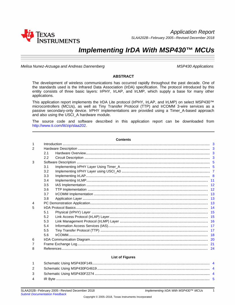
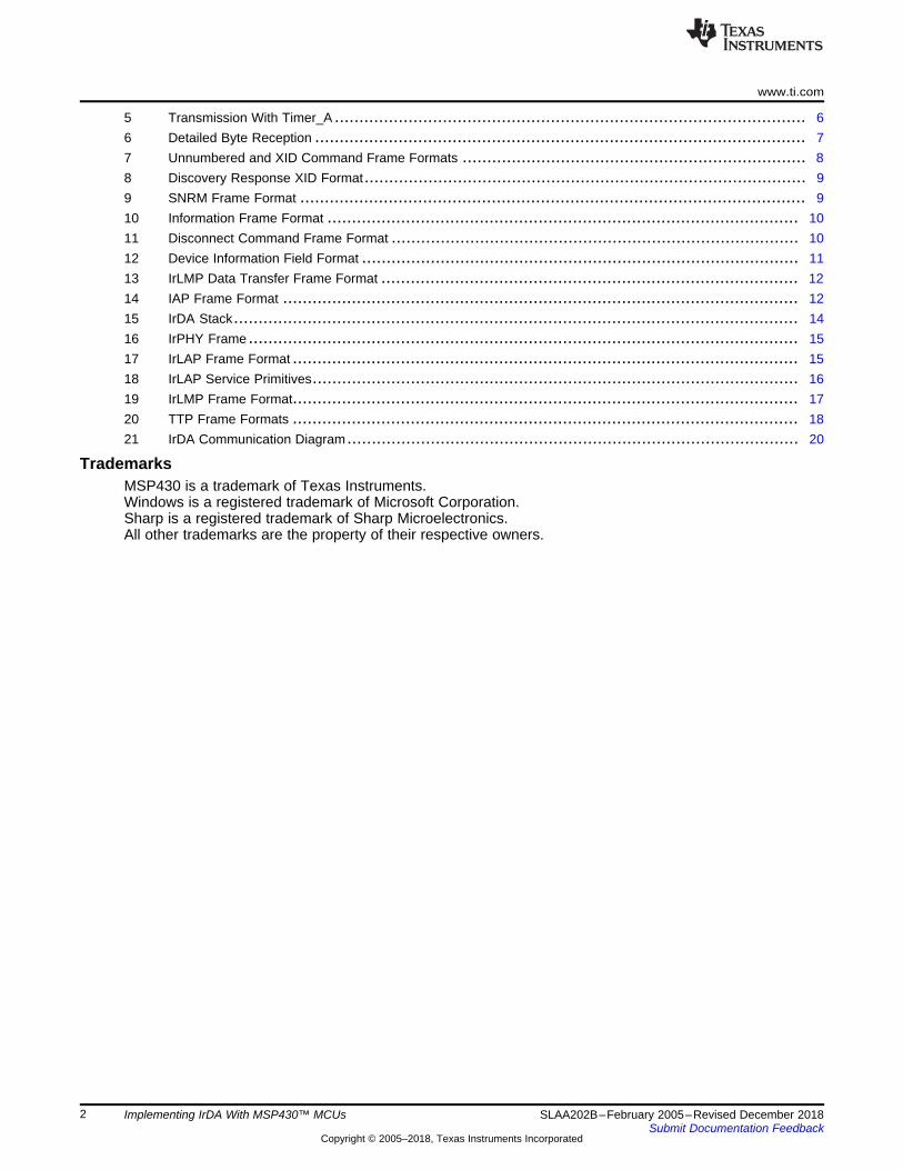
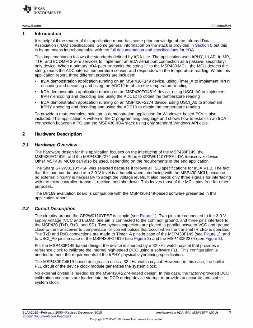
2.2 Circuit DescriptionThe circuitry around the GP2W0110YPSF is simple (see Figure 1). Two pins are connected to the 3.0-Vsupply voltage (VCC and LEDA), one pin is connected to the common ground, and three pins interface tothe MSP430 (TxD, RxD, and SD). Two bypass capacitors are placed in parallel between VCC and groundclose to the transceiver to compensate for current pulses that occur when the transmit IR LED is operated.The TxD and RxD connections are made to Timer_A pins in case of the MSP430F149 (see Figure 1), andto USCI_A0 pins in case of the MSP430FG4619 (see Figure 2) and the MSP430F2274 (see Figure 3).
For the MSP430F149-based design, the device is sourced by a 32-kHz watch crystal that provides areference clock to calibrate the internal high-speed DCO using a software FLL. This configuration isneeded to meet the requirements of the IrPHY physical layer timing specification.
The MSP430FG4619-based design also uses a 32-kHz watch crystal. However, in this case, the built-inFLL circuit of the device clock module generates the system clock.
No external crystal is needed for the MSP430F2274-based design. In this case, the factory-provided DCOcalibration constants are loaded into the DCO during device startup, to provide an accurate and stablesystem clock.
RST
DVCC
AVCC
DVSS
AVSS
P3.4/UCA0TXD
P3.5/UCA0RXD
P1.3
0.1 µF
MSP430F22743 V
TxD
RxD
SD
LEDA
GND
VCC
GP2W0110YPSF3 V
22 µF
0.1 µF
RST
DVCC
AVCC
DVSS
AVSS
P2.4/UCA0TXD
P2.5/UCA0RXD
XIN
XOUT
P1.3
0.1 µF
MSP430FG4619
32 kHz
3 V
TxD
RxD
SD
LEDA
GND
VCC
GP2W0110YPSF3 V
22 µF
0.1 µF
RST
DVCC
AVCC
DVSS
AVSS
P1.6/TA1
P1.2/TA1
XIN
XOUT
P1.3
0.1 µF
MSP430F149
32 kHz
3 V
TxD
RxD
SD
LEDA
GND
VCC
GP2W0110YPSF3 V
22 µF
0.1 µF
Hardware Description www.ti.com
4 SLAA202B–February 2005–Revised December 2018Submit Documentation Feedback
Copyright © 2005–2018, Texas Instruments Incorporated
Implementing IrDA With MSP430™ MCUs
Figure 1. Schematic Using MSP430F149
Figure 2. Schematic Using MSP430FG4619
Figure 3. Schematic Using MSP430F2274
Data Bits
Pulse Width
3/16 Bit Time
Stop
Bit
Start
Bit
Bit
Time
0 1 0 1 0 0 1 1 0 1
www.ti.com Software Description
5SLAA202B–February 2005–Revised December 2018Submit Documentation Feedback
Copyright © 2005–2018, Texas Instruments Incorporated
Implementing IrDA With MSP430™ MCUs
3 Software DescriptionThis section provides a description of the implemented IrDA protocol stack. The entire demonstrationapplication is written in assembly language and resides in one file. Functions have been named in wayswhich make it simple to understand which layer they belong to and what their functionality is. All serviceprimitives for the IrPHY, IrLAP, and IrLMP layers have been implemented as specified by the IrDA Litedocumentation. The TTP and IrCOMM 3-wire cooked services have been implemented to provide ademonstration of the working stack.
This chapter discusses two different implementation methods of the IrPHY layer. The first method usesTimer_A, and is utilized by the MSP430F149-based design discussed in this application report. Thesecond method uses the USCI_A0 hardware communication module, and is used by bothMSP430FG4619- and MSP430F2274-based designs. However all designs use the exact same IrDAcommunication algorithms.
3.1 Implementing IrPHY Layer Using Timer_AThe Timer_A peripheral module found on all MSP430s can be used to implement the IrPHY layer, in casethat no hardware module with IrDA support is available.
The approach is to design a unit that behaves as a UART but processes data received from and sent tothe IR transceiver. The IR-pulse duty cycle is 3/16th of a bit period as specified in the IrPHYdocumentation. The transmission and reception schemes are similar.
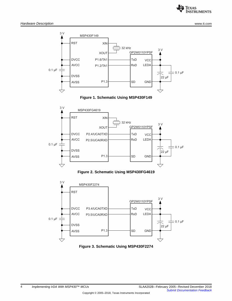
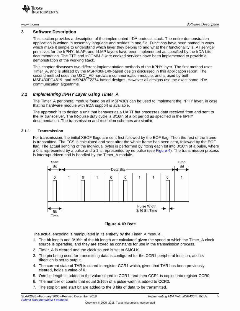
3.1.1 TransmissionFor transmission, the initial XBOF flags are sent first followed by the BOF flag. Then the rest of the frameis transmitted. The FCS is calculated and sent after the whole frame has been sent, followed by the EOFflag. The actual sending of the individual bytes is performed by fitting each bit into 3/16th of a pulse, wherea 0 is represented by a pulse and a 1 is represented by no pulse (see Figure 4). The transmission processis interrupt driven and is handled by the Timer_A module.
Figure 4. IR Byte
The actual encoding is manipulated in its entirety by the Timer_A module.1. The bit length and 3/16th of the bit length are calculated given the speed at which the Timer_A clock
source is operating, and they are stored as constants for use in the transmission process.2. Timer_A is cleared and the clock source is set to SMCLK.3. The pin being used for transmitting data is configured for the CCR1 peripheral function, and its
direction is set to output.4. The current state of TAR is stored in register CCR1 which, given that TAR has been previously
cleared, holds a value of 0.5. One bit length is added to the value stored in CCR1, and then CCR1 is copied into register CCR0.6. The number of counts that equal 3/16th of a pulse width is added to CCR0.7. The stop bit and start bit are added to the 8 bits of data to be transmitted.
OutputMode 3:
Set/Reset
EQU1:
Set
EQU0:
Reset
EQU1:
Reset
OutputMode 5:
Reset
OutputMode 3:
Set/Reset
OutputMode 5:
Reset
EQU1:
Set
EQU0:
Reset
EQU1:
Reset
Stop BitStart Bit
0 1 0 1(...)
Data Bits
Software Description www.ti.com
6 SLAA202B–February 2005–Revised December 2018Submit Documentation Feedback
Copyright © 2005–2018, Texas Instruments Incorporated
Implementing IrDA With MSP430™ MCUs
8. The transmission counter is loaded with 10, to include the start and stop bits.9. The CCR0 interrupt is enabled in the CCTL0 control register.10. Output Mode 3 Set/Reset is selected for CCR1 to transmit the start bit.11. Timer_A is started in continuous mode.12. The CCIE flag is polled to determine when the transmission has ended, because the ISR clears the
CCIE flag when all bits of the byte have been transmitted. The CCIE flag is polled by a subroutineinside the transmission routine and as soon as the CCIE flag is cleared, the transmission routinereturns.
13. When TAR reaches CCR1, the output goes high and it returns back low when TAR reaches CCR0.This generates the start bit.
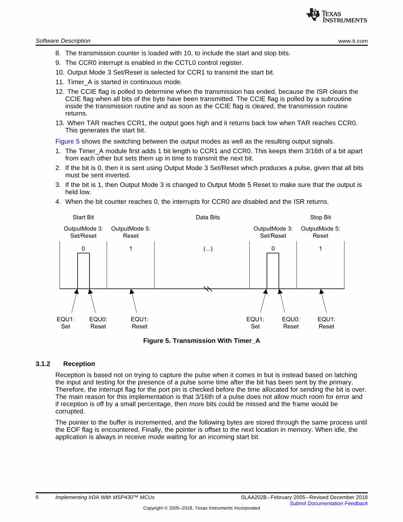
Figure 5 shows the switching between the output modes as well as the resulting output signals.1. The Timer_A module first adds 1 bit length to CCR1 and CCR0. This keeps them 3/16th of a bit apart
from each other but sets them up in time to transmit the next bit.2. If the bit is 0, then it is sent using Output Mode 3 Set/Reset which produces a pulse, given that all bits
must be sent inverted.3. If the bit is 1, then Output Mode 3 is changed to Output Mode 5 Reset to make sure that the output is
held low.4. When the bit counter reaches 0, the interrupts for CCR0 are disabled and the ISR returns.
Figure 5. Transmission With Timer_A
3.1.2 ReceptionReception is based not on trying to capture the pulse when it comes in but is instead based on latchingthe input and testing for the presence of a pulse some time after the bit has been sent by the primary.Therefore, the interrupt flag for the port pin is checked before the time allocated for sending the bit is over.The main reason for this implementation is that 3/16th of a pulse does not allow much room for error andif reception is off by a small percentage, then more bits could be missed and the frame would becorrupted.
The pointer to the buffer is incremented, and the following bytes are stored through the same process untilthe EOF flag is encountered. Finally, the pointer is offset to the next location in memory. When idle, theapplication is always in receive mode waiting for an incoming start bit.
Last Data BitFirst Data Bit Stop Bit
CCR1 Int.,
(Compare)
0 0 0(...)
Start Bit
1
Data Bits
CCR1 Int.,
(Capture)
P1IFG Set P1IFG Set
CCR1 Int.,
(Compare)
CCR1 Int.,
(Compare)
www.ti.com Software Description
7SLAA202B–February 2005–Revised December 2018Submit Documentation Feedback
Copyright © 2005–2018, Texas Instruments Incorporated
Implementing IrDA With MSP430™ MCUs
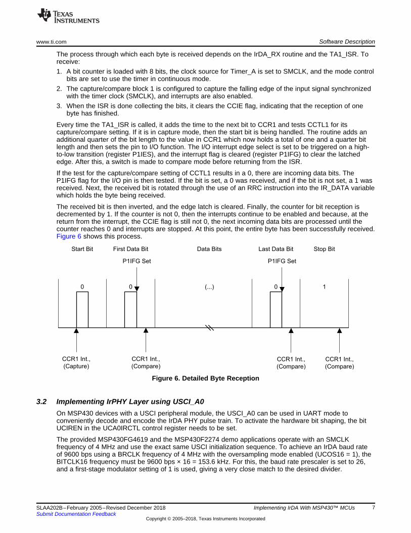
The process through which each byte is received depends on the IrDA_RX routine and the TA1_ISR. Toreceive:1. A bit counter is loaded with 8 bits, the clock source for Timer_A is set to SMCLK, and the mode control
bits are set to use the timer in continuous mode.2. The capture/compare block 1 is configured to capture the falling edge of the input signal synchronized
with the timer clock (SMCLK), and interrupts are also enabled.3. When the ISR is done collecting the bits, it clears the CCIE flag, indicating that the reception of one
byte has finished.
Every time the TA1_ISR is called, it adds the time to the next bit to CCR1 and tests CCTL1 for itscapture/compare setting. If it is in capture mode, then the start bit is being handled. The routine adds anadditional quarter of the bit length to the value in CCR1 which now holds a total of one and a quarter bitlength and then sets the pin to I/O function. The I/O interrupt edge select is set to be triggered on a high-to-low transition (register P1IES), and the interrupt flag is cleared (register P1IFG) to clear the latchededge. After this, a switch is made to compare mode before returning from the ISR.
If the test for the capture/compare setting of CCTL1 results in a 0, there are incoming data bits. TheP1IFG flag for the I/O pin is then tested. If the bit is set, a 0 was received, and if the bit is not set, a 1 wasreceived. Next, the received bit is rotated through the use of an RRC instruction into the IR_DATA variablewhich holds the byte being received.
The received bit is then inverted, and the edge latch is cleared. Finally, the counter for bit reception isdecremented by 1. If the counter is not 0, then the interrupts continue to be enabled and because, at thereturn from the interrupt, the CCIE flag is still not 0, the next incoming data bits are processed until thecounter reaches 0 and interrupts are stopped. At this point, the entire byte has been successfully received.Figure 6 shows this process.
Figure 6. Detailed Byte Reception
3.2 Implementing IrPHY Layer using USCI_A0On MSP430 devices with a USCI peripheral module, the USCI_A0 can be used in UART mode toconveniently decode and encode the IrDA PHY pulse train. To activate the hardware bit shaping, the bitUCIREN in the UCA0IRCTL control register needs to be set.
The provided MSP430FG4619 and the MSP430F2274 demo applications operate with an SMCLKfrequency of 4 MHz and use the exact same USCI initialization sequence. To achieve an IrDA baud rateof 9600 bps using a BRCLK frequency of 4 MHz with the oversampling mode enabled (UCOS16 = 1), theBITCLK16 frequency must be 9600 bps × 16 = 153.6 kHz. For this, the baud rate prescaler is set to 26,and a first-stage modulator setting of 1 is used, giving a very close match to the desired divider.
Unnumbered: XID command control:
X X X
P
/
F
X X 1 1 0 0 1 P 1 1 1 1
Software Description www.ti.com
8 SLAA202B–February 2005–Revised December 2018Submit Documentation Feedback
Copyright © 2005–2018, Texas Instruments Incorporated
Implementing IrDA With MSP430™ MCUs
The IrDA transmitter is configured to generate pulses with a pulse length of exactly 3/16th of a bit time bysetting UCIRTXCLK = 1 and UCITXPLx = 5. This setting can be reduced if a shorter pulse length ispermissible, resulting in current savings during the operation of the externally connected IrDA transceiver.The byte transmission in IrDA mode is exactly the same as in UART mode. The application ensures thatthe transmit buffer can be loaded by ensuring that UCA0TXIFG is clear, and then simply loads thetransmit data byte into UCA0TXBUF. The USCI module will then start transmitting and bit-shaping theIrDA pulse train.
The receiver configuration includes the setting of UCIRRXPL to match the polarity of the receive signalprovided by the IrDA transceiver. An optional analog deglitch filter can be configured to improve systemrobustness; however, this feature is not used here. To receive data, the USCI_A0 receive interrupt isenabled, and the low-power mode is entered. Upon the reception of a data byte, the receive interruptservice routine is entered, and the data is fetched from the UCA0RXBUF receive buffer.
For more information on the configuration and operation of the USCI module, see the MSP430F4xx orMSP430F2xx family user's guides [12][13].
3.3 Implementing IrLAPThe approach for the implementation of the IrLAP layer was to develop functions performing all the tasksdescribed in the primitives that also behave according to the state tables found in the IrDA Litedocumentation. This layer depends on the services provided by the IrPHY layer to function properly. Thislayer provides a reliable connection for data transfer.
To process the frames correctly, first it is necessary to know which of the three classes of frames is beinghandled. The three types of frames in IrLAP are supervisory (S), information (I), and unnumbered (U). Themost effective way to identify the frame is through parsing of the bytes. As soon as the byte pattern thatidentifies a certain type of frame is found, the program jumps to the routines responsible for its handling.Then, as the bytes are identified and decoded, actions are taken depending on the primitive to which theycorrespond as shown below in a code excerpt from the application. This routine is calledIR_MSG_PROCESS, and it is the piece of code responsible for parsing of the frame and sending the datato the right primitive for processing.
It is simple to identify which type of frame was received, given the bytes used to identify each command. Itis enough to check one or two bits of the byte which are in a certain position to identify the IrLAPcommand that was received. After the command has been identified, the proper response is generatedand sent through the IrPHY layer to the transceiver. After this, the program goes back to the main loopand waits until the next frame is received from the primary.
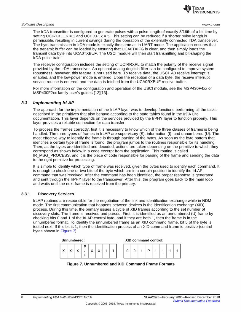
3.3.1 Discovery ServicesIrLAP routines are responsible for the negotiation of the link and identification exchange while in NDMmode. The first communication that happens between devices is the identification exchange (XID)process. During this time, the primary issues a cycle of XID frames according to the set number ofdiscovery slots. The frame is received and parsed. First, it is identified as an unnumbered (U) frame bychecking bits 0 and 1 of the IrLAP control byte, and if they are both 1, then the frame is in theunnumbered format. To identify the unnumbered frame as an XID command frame, bit 5 of the byte istested next. If this bit is 1, then the identification process of an XID command frame is positive (controlbytes shown in Figure 7).
Figure 7. Unnumbered and XID Command Frame Formats
N Bytes1 Byte4 Bytes 4 Bytes
New Connection Address
Source
Device Address
Destination
Device Address
Conn.
Addr.
C
/
R
Negotiation Parameters
1 Byte
XID
Cmd.
1 Byte
ADDR
1 Byte 1 Byte 1 Byte4 Bytes 4 Bytes 1 Byte 1 Byte 32 Bytes1 Byte
ADDRXID
Resp.
Form.
ID
Source
Device Address
Destination
Device Address
Disc.
Flags
Slot
Nr.
Ver.
Nr.
Discovery
Info
www.ti.com Software Description
9SLAA202B–February 2005–Revised December 2018Submit Documentation Feedback
Copyright © 2005–2018, Texas Instruments Incorporated
Implementing IrDA With MSP430™ MCUs
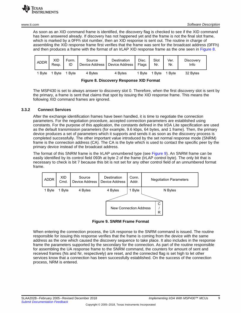
As soon as an XID command frame is identified, the discovery flag is checked to see if the XID commandhas been answered already. If discovery has not happened yet and the frame is not the final slot frame,which is marked by a 0FFh slot number, then an XID response is sent out. The routine in charge ofassembling the XID response frame first verifies that the frame was sent for the broadcast address (0FFh)and then produces a frame with the format of an IrLAP XID response frame as the one seen in Figure 8.
Figure 8. Discovery Response XID Format
The MSP430 is set to always answer to discovery slot 0. Therefore, when the first discovery slot is sent bythe primary, a frame is sent that claims that spot by issuing the XID response frame. This means thefollowing XID command frames are ignored.
3.3.2 Connect ServicesAfter the exchange identification frames have been handled, it is time to negotiate the connectionparameters. For the negotiation procedure, accepted connection parameters are established usingconstants. For the purpose of this application, the constants defined in the IrDA Lite specification are usedas the default transmission parameters (for example, 9.6 kbps, 64 bytes, and 1 frame). Then, the primarydevice produces a set of parameters which it supports and sends it as soon as the discovery process iscompleted successfully. The other important value introduced by the set normal response mode (SNRM)frame is the connection address (CA). The CA is the byte which is used to contact the specific peer by theprimary device instead of the broadcast address.
The format of this SNRM frame is the IrLAP unnumbered type (see Figure 9). An SNRM frame can beeasily identified by its control field 093h at byte 2 of the frame (IrLAP control byte). The only bit that isnecessary to check is bit 7 because this bit is not set for any other control field of an unnumbered formatframe.
Figure 9. SNRM Frame Format
When entering the connection process, the UA response to the SNRM command is issued. The routineresponsible for issuing this response verifies that the frame is coming from the device with the sameaddress as the one which caused the discovery sequence to take place. It also includes in the responseframe the parameters supported by the secondary for the connection. As part of the routine responsiblefor assembling the UA response frame to the SNRM command, the counters for amount of sent andreceived frames (Ns and Nr, respectively) are reset, and the connected flag is set high to let otherservices know that a connection has been successfully established. On the success of the connectionprocess, NRM is entered.
1 Byte
DISC
Cmd.
1 Byte
ADDR
P
/
F
NS
1 Byte 1 Byte
ADDR CTRL
N Bytes
DATA
NR 0
Software Description www.ti.com
10 SLAA202B–February 2005–Revised December 2018Submit Documentation Feedback
Copyright © 2005–2018, Texas Instruments Incorporated
Implementing IrDA With MSP430™ MCUs
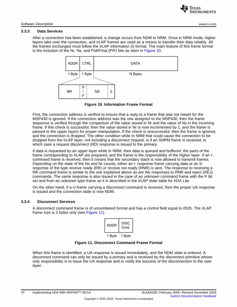
3.3.3 Data ServicesAfter a connection has been established, a change occurs from NDM to NRM. Once in NRM mode, higherlayers take over the connection, and IrLAP frames are used as a means to transfer their data reliably. Allthe frames exchanged must follow the IrLAP information (I) format. The main feature of this frame formatis the inclusion of the Nr, Ns, and Poll/Final (P/F) bits as seen in Figure 10.
Figure 10. Information Frame Format
First, the connection address is verified to ensure that a reply to a frame that was not meant for theMSP430 is ignored. If the connection address was the one assigned to the MSP430, then the framesequence is verified through the comparison of the value stored in Nr and the value of Ns in the incomingframe. If this check is successful, then the value stored in Nr is now incremented by 1, and the frame ispassed to the upper layers for proper manipulation. If the check is unsuccessful, then the frame is ignored,and the connection is dropped. The other condition while in NRM that could cause the connection to bedropped from the IrLAP layer, not including a disconnect request, is if an SNRM frame is received, inwhich case a request disconnect (RD) response is issued to the primary.
If data is requested by an upper layer while in NRM, then data is queued and buffered, the parts of theframe corresponding to IrLAP are prepared, and the frame is the responsibility of the higher layer. If an I-command frame is received, then it means that the secondary stack is now allowed to transmit frames.Depending on the state of the Ns and Nr counts, either an I- response frame carrying data or an S-response of the type receive ready (RR) or receive not ready (RNR) is sent. The response to receiving aRR command frame is similar to the one explained above as are the responses to RNR and reject (REJ)commands. The same response is also issued in the case of an unknown command frame with the P bitset and from an unknown type frame as it is described in the IrLAP state table for IrDA Lite.
On the other hand, if a U-frame carrying a disconnect command is received, then the proper UA responseis issued and the connection state is now NDM.
3.3.4 Disconnect ServicesA disconnect command frame is of unnumbered format and has a control field equal to 053h. The IrLAPframe size is 2 bytes only (see Figure 11).
Figure 11. Disconnect Command Frame Format
When this frame is identified, a UA response is issued immediately, and the NDM state is entered. Adisconnect command can only be issued by a primary and is received by the disconnect primitive whoseonly responsibility is to issue the UA response and to notify the success of the disconnection to the userlayer.
1 Byte
Char.
Set
N Bytes
Service Hints
< (23 - N) Bytes
DATA
www.ti.com Software Description
11SLAA202B–February 2005–Revised December 2018Submit Documentation Feedback
Copyright © 2005–2018, Texas Instruments Incorporated
Implementing IrDA With MSP430™ MCUs
3.4 Implementing IrLMPThe implementation of the IrLMP layer was accomplished by following the specifications of the IrDA Litedocumentation. The main task of this layer is to verify that the DLSAP-SEL and SLSAP-SEL values arecorrect and that the correct service is using them. It also verifies that the services requested by the peerare supported as specified in the GetValueByClass function. Finally, it provides the frame format thatcarries the data to be exchanged by the two devices.
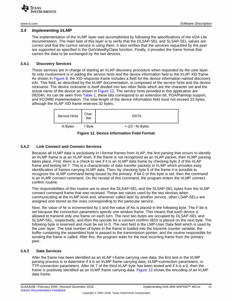
3.4.1 Discovery ServicesThese services are in charge of starting an IrLAP discovery procedure when requested by the user layer.Its only involvement is in adding the service hints and the device information field to the IrLAP XID frame.As shown in Figure 8, the XID response frame includes a field for the device information named discoveryinfo. This field, as described by the IrLMP documentation, is composed of the service hints and the devicenickname. The device nickname is itself divided into two other fields which are the character set and theactual name of the device as shown in Figure 12. The service hints provided in this application are08204h. As can be seen from Table 1, these bits correspond to an extension bit, PDA/Palmtop support,and IrCOMM implementation. The total length of the device information field must not exceed 23 bytes,although the IrLAP XID frame reserves 32 bytes.
Figure 12. Device Information Field Format
3.4.2 Link Connect and Connect ServicesBecause all IrLMP data is exclusively in I-format frames from IrLAP, the first parsing that occurs to identifyan IrLMP frame is at an IrLAP level. If the frame is not recognized as an IrLAP packet, then IrLMP parsingtakes place. First, there is a check to see if it is an IrLMP data frame by checking byte 3 of the IrLAPframe and testing bit 7. This is a characteristic of data transfer packets in IrLMP which provides easyidentification of frames carrying IrLMP data. Then, by checking byte 5 of the frame it is possible torecognize the IrLMP command being issued by the primary. If bit 0 of this byte is set, then the commandis an IrLMP connect command. On the receipt of this command, the program enters the IrLMP connectconfirm routine.
The responsibilities of this routine are to store the DLSAP-SEL and the SLSAP-SEL bytes from the IrLMPconnect command frame that was received. These are values used by the two devices whencommunicating at the IrLMP level and, whenever called later by another service, other LSAP-SELs areassigned and stored as the ones corresponding to the particular service.
Next, the value of Nr is incremented by 1 and the value of Ns is placed in the following byte. The F bit isset because the connection parameters specify one window frame. This means that each device isallowed to transmit only one frame on each turn. The next two bytes are occupied by DLSAP-SEL andSLSAP-SEL, respectively, and then the opcode for a connect confirm 081h is placed on the next byte. Thefollowing byte is reserved and must be set to 0. The next field is the LMP-User Data field which is used bythe user layer. The total number of bytes in the frame is loaded into the transmit counter variable, thebuffer containing the assembled byte is passed to the transmission pointer, and the routine responsible forsending the frame is called. After this, the program waits for the next incoming frame from the primarypeer.
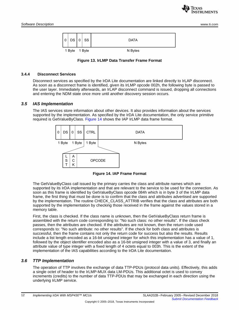
3.4.3 Data ServicesAfter the frame has been identified as an IrLAP I-frame carrying user-data, the first test in the IrLMPparsing process is to determine if it is an IrLMP frame carrying data, IrLMP-connection parameters, orTTP-connection parameters. After bit 7 of the third IrLAP byte has been tested and if it is a 0, then theframe is positively identified as an IrLMP frame carrying data. Figure 13 shows the encoding of an IrLMPdata frame.
A
C
K
1 Byte1 Byte 1 Byte N Bytes
0 DS 0 SS DATA
L
S
T
OPCODE
CTRL
1 Byte 1 Byte N Bytes
0 DS 0 SS DATA
Software Description www.ti.com
12 SLAA202B–February 2005–Revised December 2018Submit Documentation Feedback
Copyright © 2005–2018, Texas Instruments Incorporated
Implementing IrDA With MSP430™ MCUs
Figure 13. IrLMP Data Transfer Frame Format
3.4.4 Disconnect ServicesDisconnect services as specified by the IrDA Lite documentation are linked directly to IrLAP disconnect.As soon as a disconnect frame is identified, given its IrLMP opcode 002h, the following byte is passed tothe user layer. Immediately afterwards, an IrLAP disconnect command is issued, dropping all connectionsand entering the NDM state once more until another discovery session occurs.
3.5 IAS ImplementationThe IAS services store information about other devices. It also provides information about the servicessupported by the implementation. As specified by the IrDA Lite documentation, the only service primitiverequired is GetValueByClass. Figure 14 shows the IAP IrLMP data frame format.
Figure 14. IAP Frame Format
The GetValueByClass call issued by the primary carries the class and attribute names which aresupported by its IrDA implementation and that are relevant to the service to be used for the connection. Assoon as this frame is identified by GetValueByClass opcode 084h which is in byte 3 of the IrLMP dataframe, the first thing that must be done is to confirm that the class and attributes advertised are supportedby the implementation. The routine CHECK_CLASS_ATTRIB verifies that the class and attributes are bothsupported by the implementation by checking those received in the frame against the values stored in amemory table.
First, the class is checked. If the class name is unknown, then the GetValueByClass return frame isassembled with the return code corresponding to: "No such class: no other results". If the class checkpasses, then the attributes are checked. If the attributes are not known, then the return code usedcorresponds to: "No such attribute: no other results". If the check for both class and attributes issuccessful, then the frame contains not only the return code for success but also the results. Resultsinclude a list length encoded as a 16-bit unsigned integer for which this implementation has a value of 1,followed by the object identifier encoded also as a 16-bit unsigned integer with a value of 3, and finally anattribute value of type integer with a fixed length of 4 octets equal to 003h. This is the extent of theimplementation of the IAS capabilities according to the IrDA Lite documentation.
3.6 TTP ImplementationThe operation of TTP involves the exchange of data TTP-PDUs (protocol data units). Effectively, this addsa single octet of header to the IrLMP-MUX data LM-PDUs. This additional octet is used to conveyincrements (credits) to the number of data TTP-PDUs that may be exchanged in each direction using theunderlying IrLMP service.
www.ti.com Software Description
13SLAA202B–February 2005–Revised December 2018Submit Documentation Feedback
Copyright © 2005–2018, Texas Instruments Incorporated
Implementing IrDA With MSP430™ MCUs
In this implementation, a simple policy for advancing credit is used. This means that the credit is heldlonger at AvailCredit rather than being advanced at the earliest opportunity. This leaves buffers availableto be reclaimed and redeployed to other needy TTP connections or to relieve resource problemselsewhere in a system.
Connect TTP-PDUs exchanged during connection establishment are not regarded as requiring orconsuming credit. Segmentation and reassembly is not implemented. Because the IrLAP window size isequal to 1, a single TTP connection can take full advantage of the underlying IrLAP window.
For this particular implementation, when the initial TTP connection frame is identified, credit is issued sothat the peer entity can transfer its data. As soon as the MSP430 responds and after it has received anRR command from the primary, it then issues more credit for the peer entity to continue transmitting data.
3.7 IrCOMM ImplementationThis is the layer that is in charge of the actual data exchange. The only times when it does not use theIrLMP services is for identifying the frames that carry user data, for constructing the frames that send datato the peer device, and when dealing with TTP services. For connection and disconnection, it uses therespective IrLMP services.
IrCOMM services are the same services as provided by the IrLMP layer. IrCOMM uses the servicesprovided by the service layer, and this call would propagate down the protocol stack. It uses the dataPDUs from IrLMP to transmit all data and control channel information. These two types of frames can bedifferentiated because when sending data there is an overhead of two bytes. The first byte is equal to theamount of credit that the peer has left to transmit after the data-carrying frame is received, and the secondone is equal to 0 following the IrLMP LM-MUX overhead. In the case of the connection frames, a controlfield follows the TTP overhead where the first byte indicates the length in bytes of the connectionparameters. As the connection parameters for IrLAP and TTP, these are in groups of three.
3.8 Application LayerThe application layer is the layer that uses the services provided by the stack to perform a specific task. Inthis case, for demonstrating functionality, the user layer waits for the ASCII character 't'. After thecharacter has been received, the MSP430 obtains a temperature reading from the ADC module integratedtemperature sensor and appends it through the use of the IrCOMM layer to the user data field of a datacarrying IrLMP frame. The temperature sent then is displayed by the peer device, and the MSP430 thenissues more credit to the peer entity so that more data can be sent.
4 PC Demonstration ApplicationThe PC demonstration application supplied with this application report is provided as both C source codeand as an executable single-file Win32 command line application. It has been decided to develop thesoftware as a command line application to make it both easy to understand and also compatible with allcommon Windows-based C development systems such as Microsoft Visual C++ or Borland C++. Thedemonstration software requires at least Windows 2000 or Windows XP operating system and a properlyinstalled infrared port. This IR port can either be integrated (such as found in notebook computers) orprovided by an external Windows-supported IrDA adaptor (for example, the Actisys ACT-IR220L+).
The current Windows operating systems come with a built-in IrDA stack that implements various IrDAcommunication modes, such as the 9-wire IrCOMM mode. This mode can easily interface with externaldevices like PDAs, cell-phones, and the presented MSP430 IrDA stack. Microsoft decided to expose theIrDA stack through the Windows sockets library rather than by providing virtual COM ports. If virtual COMports need to be used, then additional third-party driver software such as IrCOMM2k is required [9].However, the more elegant approach is to perform IrDA communication by using the standard Windowsbuilt-in driver model as shown in this demonstration application.
The PC demonstration application provides feedback about every Windows API call it does. If one of thecalls fail, the application terminates and displays the Windows error code as obtained by the Windowssockets function WSAGetLastError(). For detailed information about the error codes, see the MicrosoftWindows Platform SDK documentation [8].
IR Adapter
IrPHY (Physical Layer)
IrLAP (Link Access Protocol Layer)
IrLMP (Link Management Layer)
IAS (Information
Access Services)
TTP
(Tiny Transport
Protocol)
IrCOMM,
OBEX, IrLAN,
IrFM, etc.
IrDA Protocol Basics www.ti.com
14 SLAA202B–February 2005–Revised December 2018Submit Documentation Feedback
Copyright © 2005–2018, Texas Instruments Incorporated
Implementing IrDA With MSP430™ MCUs
When starting the application, it tries to open the Winsock system library (DLL). At least version 2.2 isrequired for proper operation of the IrDA communication. The program exits with an error message if anincompatible version is located. After opening the Windows IrDA socket, the reception and transmittimeouts are configured to 3 seconds to prevent the software from indefinitely waiting for the end of thecommunication. The software then generates a list of IrDA devices which have been discovered already.For the sake of simplicity, the first device is taken from the list and assumed to be the IrDA peer the userwants to communicate with. At this point, the user could be provided with a list of the discovered devices.Next, the peer's IAS database is scanned to check whether or not it supports the 9-wire communicationmode. If the 9-wire mode is supported, then it is activated. Otherwise, the application terminates with anerror message.
From this point on, using the Windows IrDA stack does not differ from using any other Windows socketssuch as TCP or UDP. The connection is opened by calling the connect() function. After that, a single tcharacter is transmitted using send(). When the MSP430 IrDA stack receives this character, it initiates anA/D conversion of the ADC12 module internal temperature sensor and then sends back the current MCUtemperature as an ASCII string. Finally, the data that was received and buffered by the Windows IrDAstack is read out using the sockets function recv() and displayed on the screen. The Windows socket andtherefore the IrDA stack are now closed by calling closesocket(). It is important that the socket is closedevery time it has been used, even if an error occurred. Otherwise, internal Windows IrDA stack resourcescould remain locked and the IrDA port can no longer be accessed until the next system start-up.Therefore, make sure not to interrupt the demo application by not pressing Ctrl+C. Detailed informationabout the built-in Windows IrDA functionality can be found in the Microsoft Windows Platform SDK.
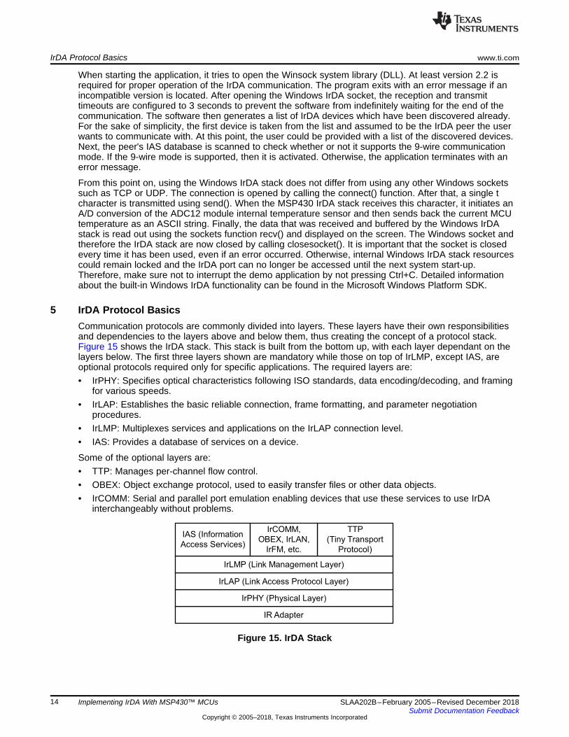
5 IrDA Protocol BasicsCommunication protocols are commonly divided into layers. These layers have their own responsibilitiesand dependencies to the layers above and below them, thus creating the concept of a protocol stack.Figure 15 shows the IrDA stack. This stack is built from the bottom up, with each layer dependant on thelayers below. The first three layers shown are mandatory while those on top of IrLMP, except IAS, areoptional protocols required only for specific applications. The required layers are:• IrPHY: Specifies optical characteristics following ISO standards, data encoding/decoding, and framing
for various speeds.• IrLAP: Establishes the basic reliable connection, frame formatting, and parameter negotiation
procedures.• IrLMP: Multiplexes services and applications on the IrLAP connection level.• IAS: Provides a database of services on a device.
Some of the optional layers are:• TTP: Manages per-channel flow control.• OBEX: Object exchange protocol, used to easily transfer files or other data objects.• IrCOMM: Serial and parallel port emulation enabling devices that use these services to use IrDA
interchangeably without problems.
Figure 15. IrDA Stack
1 Byte N Bytes1 Byte
DATACTRLADDR
Connection Address
C
/
R
N Bytes1 Byte 2 Bytes 1 Byte10 Bytes
DATABOF EOFFCSXBOF
www.ti.com IrDA Protocol Basics
15SLAA202B–February 2005–Revised December 2018Submit Documentation Feedback
Copyright © 2005–2018, Texas Instruments Incorporated
Implementing IrDA With MSP430™ MCUs
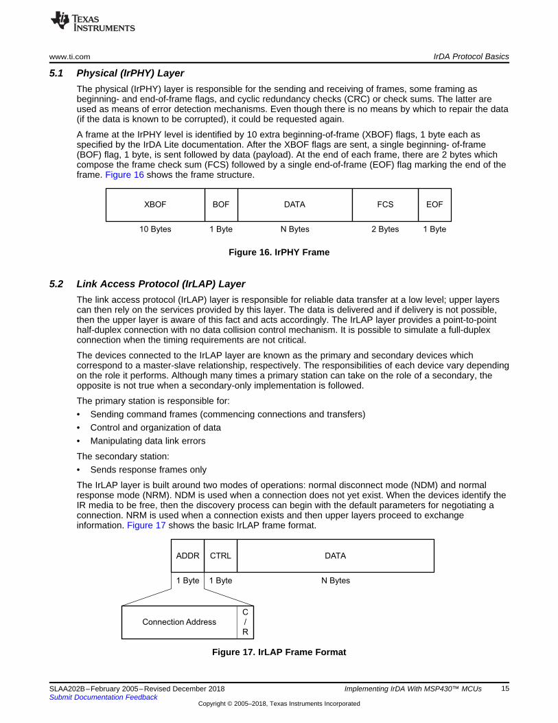
5.1 Physical (IrPHY) LayerThe physical (IrPHY) layer is responsible for the sending and receiving of frames, some framing asbeginning- and end-of-frame flags, and cyclic redundancy checks (CRC) or check sums. The latter areused as means of error detection mechanisms. Even though there is no means by which to repair the data(if the data is known to be corrupted), it could be requested again.
A frame at the IrPHY level is identified by 10 extra beginning-of-frame (XBOF) flags, 1 byte each asspecified by the IrDA Lite documentation. After the XBOF flags are sent, a single beginning- of-frame(BOF) flag, 1 byte, is sent followed by data (payload). At the end of each frame, there are 2 bytes whichcompose the frame check sum (FCS) followed by a single end-of-frame (EOF) flag marking the end of theframe. Figure 16 shows the frame structure.
Figure 16. IrPHY Frame
5.2 Link Access Protocol (IrLAP) LayerThe link access protocol (IrLAP) layer is responsible for reliable data transfer at a low level; upper layerscan then rely on the services provided by this layer. The data is delivered and if delivery is not possible,then the upper layer is aware of this fact and acts accordingly. The IrLAP layer provides a point-to-pointhalf-duplex connection with no data collision control mechanism. It is possible to simulate a full-duplexconnection when the timing requirements are not critical.
The devices connected to the IrLAP layer are known as the primary and secondary devices whichcorrespond to a master-slave relationship, respectively. The responsibilities of each device vary dependingon the role it performs. Although many times a primary station can take on the role of a secondary, theopposite is not true when a secondary-only implementation is followed.
The primary station is responsible for:• Sending command frames (commencing connections and transfers)• Control and organization of data• Manipulating data link errors
The secondary station:• Sends response frames only
The IrLAP layer is built around two modes of operations: normal disconnect mode (NDM) and normalresponse mode (NRM). NDM is used when a connection does not yet exist. When the devices identify theIR media to be free, then the discovery process can begin with the default parameters for negotiating aconnection. NRM is used when a connection exists and then upper layers proceed to exchangeinformation. Figure 17 shows the basic IrLAP frame format.
Figure 17. IrLAP Frame Format
Upper Layers
(Primary)
Request
Confirm
IrLAP Layer
(Primary)
Frames
IrLAP Layer
(Secondary)
Response
Indication
Upper Layers
(Secondary)
IrDA Protocol Basics www.ti.com
16 SLAA202B–February 2005–Revised December 2018Submit Documentation Feedback
Copyright © 2005–2018, Texas Instruments Incorporated
Implementing IrDA With MSP430™ MCUs
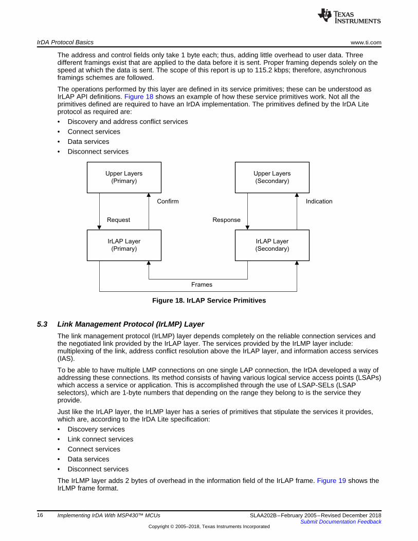
The address and control fields only take 1 byte each; thus, adding little overhead to user data. Threedifferent framings exist that are applied to the data before it is sent. Proper framing depends solely on thespeed at which the data is sent. The scope of this report is up to 115.2 kbps; therefore, asynchronousframings schemes are followed.
The operations performed by this layer are defined in its service primitives; these can be understood asIrLAP API definitions. Figure 18 shows an example of how these service primitives work. Not all theprimitives defined are required to have an IrDA implementation. The primitives defined by the IrDA Liteprotocol as required are:• Discovery and address conflict services• Connect services• Data services• Disconnect services
Figure 18. IrLAP Service Primitives
5.3 Link Management Protocol (IrLMP) LayerThe link management protocol (IrLMP) layer depends completely on the reliable connection services andthe negotiated link provided by the IrLAP layer. The services provided by the IrLMP layer include:multiplexing of the link, address conflict resolution above the IrLAP layer, and information access services(IAS).
To be able to have multiple LMP connections on one single LAP connection, the IrDA developed a way ofaddressing these connections. Its method consists of having various logical service access points (LSAPs)which access a service or application. This is accomplished through the use of LSAP-SELs (LSAPselectors), which are 1-byte numbers that depending on the range they belong to is the service theyprovide.
Just like the IrLAP layer, the IrLMP layer has a series of primitives that stipulate the services it provides,which are, according to the IrDA Lite specification:• Discovery services• Link connect services• Connect services• Data services• Disconnect services
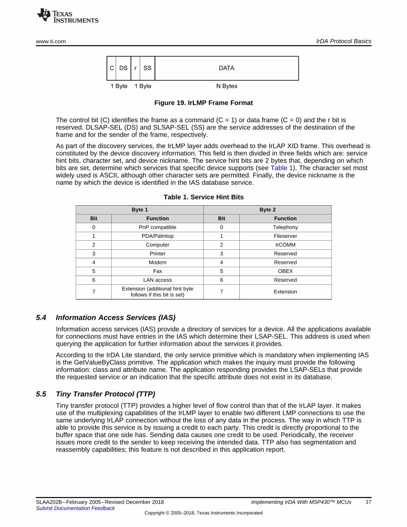
The IrLMP layer adds 2 bytes of overhead in the information field of the IrLAP frame. Figure 19 shows theIrLMP frame format.
1 Byte 1 Byte N Bytes
C DS r SS DATA
www.ti.com IrDA Protocol Basics
17SLAA202B–February 2005–Revised December 2018Submit Documentation Feedback
Copyright © 2005–2018, Texas Instruments Incorporated
Implementing IrDA With MSP430™ MCUs
Figure 19. IrLMP Frame Format
The control bit (C) identifies the frame as a command (C = 1) or data frame (C = 0) and the r bit isreserved. DLSAP-SEL (DS) and SLSAP-SEL (SS) are the service addresses of the destination of theframe and for the sender of the frame, respectively.
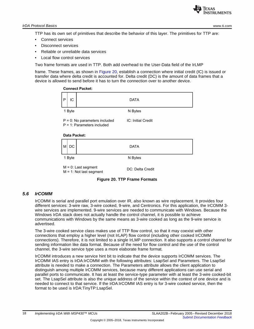
As part of the discovery services, the IrLMP layer adds overhead to the IrLAP XID frame. This overhead isconstituted by the device discovery information. This field is then divided in three fields which are: servicehint bits, character set, and device nickname. The service hint bits are 2 bytes that, depending on whichbits are set, determine which services that specific device supports (see Table 1). The character set mostwidely used is ASCII, although other character sets are permitted. Finally, the device nickname is thename by which the device is identified in the IAS database service.
Table 1. Service Hint Bits
Byte 1 Byte 2Bit Function Bit Function0 PnP compatible 0 Telephony1 PDA/Palmtop 1 Fileserver2 Computer 2 IrCOMM3 Printer 3 Reserved4 Modem 4 Reserved5 Fax 5 OBEX6 LAN access 6 Reserved
7 Extension (additional hint bytefollows if this bit is set) 7 Extension
5.4 Information Access Services (IAS)Information access services (IAS) provide a directory of services for a device. All the applications availablefor connections must have entries in the IAS which determine their LSAP-SEL. This address is used whenquerying the application for further information about the services it provides.
According to the IrDA Lite standard, the only service primitive which is mandatory when implementing IASis the GetValueByClass primitive. The application which makes the inquiry must provide the followinginformation: class and attribute name. The application responding provides the LSAP-SELs that providethe requested service or an indication that the specific attribute does not exist in its database.
5.5 Tiny Transfer Protocol (TTP)Tiny transfer protocol (TTP) provides a higher level of flow control than that of the IrLAP layer. It makesuse of the multiplexing capabilities of the IrLMP layer to enable two different LMP connections to use thesame underlying IrLAP connection without the loss of any data in the process. The way in which TTP isable to provide this service is by issuing a credit to each party. This credit is directly proportional to thebuffer space that one side has. Sending data causes one credit to be used. Periodically, the receiverissues more credit to the sender to keep receiving the intended data. TTP also has segmentation andreassembly capabilities; this feature is not described in this application report.
Data Packet:
Connect Packet:
1 Byte N Bytes
1 Byte
P = 0: No parameters included
P = 1: Parameters included
N Bytes
P IC DATA
M = 0: Last segment
M = 1: Not last segment
M DC DATA
IC: Initial Credit
DC: Delta Credit
IrDA Protocol Basics www.ti.com
18 SLAA202B–February 2005–Revised December 2018Submit Documentation Feedback
Copyright © 2005–2018, Texas Instruments Incorporated
Implementing IrDA With MSP430™ MCUs
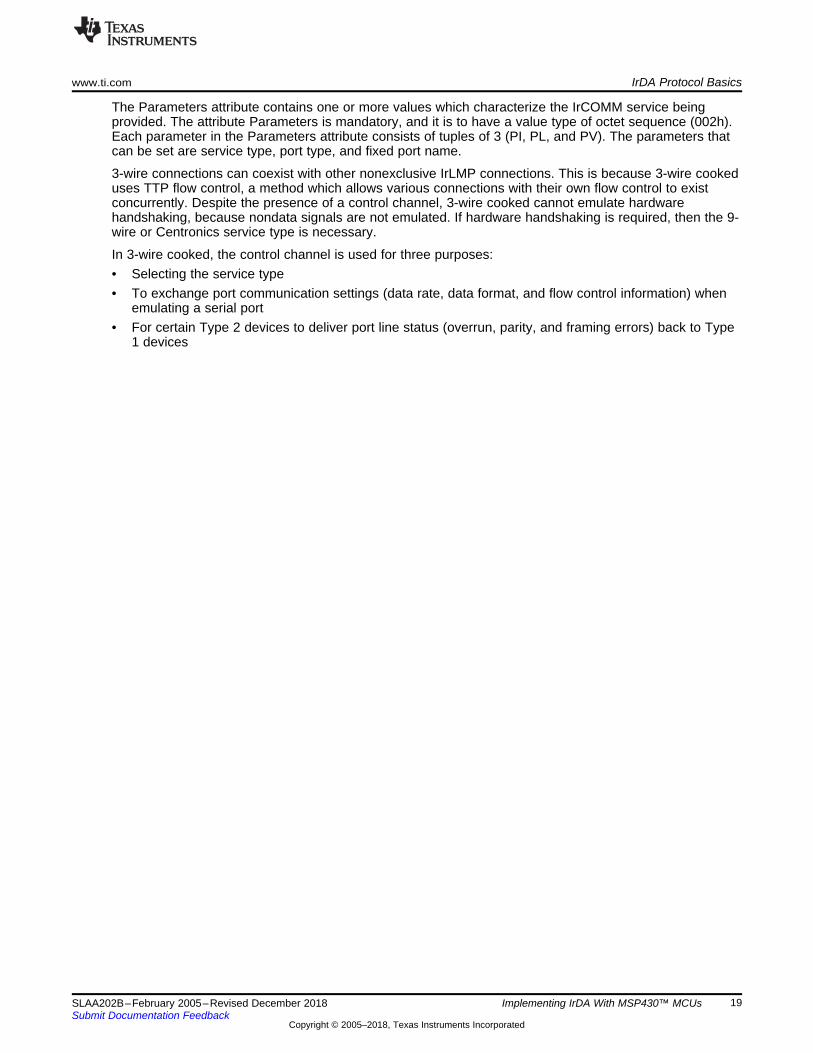
TTP has its own set of primitives that describe the behavior of this layer. The primitives for TTP are:• Connect services• Disconnect services• Reliable or unreliable data services• Local flow control services
Two frame formats are used in TTP. Both add overhead to the User-Data field of the IrLMP
frame. These frames, as shown in Figure 20, establish a connection where initial credit (IC) is issued ortransfer data where delta credit is accounted for. Delta credit (DC) is the amount of data frames that adevice is allowed to send before it has to turn the connection over to another device.
Figure 20. TTP Frame Formats
5.6 IrCOMMIrCOMM is serial and parallel port emulation over IR, also known as wire replacement. It provides fourdifferent services: 3-wire raw, 3-wire cooked, 9-wire, and Centronics. For this application, the IrCOMM 3-wire services are implemented. 9-wire services are needed to communicate with Windows. Because theWindows IrDA stack does not actually handle the control channel, it is possible to achievecommunications with Windows by the same means as 3-wire cooked as long as the 9-wire service isadvertised.
The 3-wire cooked service class makes use of TTP flow control, so that it may coexist with otherconnections that employ a higher level (not IrLAP) flow control (including other cooked IrCOMMconnections). Therefore, it is not limited to a single IrLMP connection. It also supports a control channel forsending information like data format. Because of the need for flow control and the use of the controlchannel, the 3-wire service type uses a more elaborate frame format.
IrCOMM introduces a new service hint bit to indicate that the device supports IrCOMM services. TheIrCOMM IAS entry is IrDA:IrCOMM with the following attributes: LsapSel and Parameters. The LsapSelattribute is needed to make a connection. The Parameters attribute allows the client application todistinguish among multiple IrCOMM services, because many different applications can use serial andparallel ports to communicate. It has at least the service-type parameter with at least the 3-wire cooked-bitset. The LsapSel attribute is also the unique address of the service within the context of one device and isneeded to connect to that service. If the IrDA:IrCOMM IAS entry is for 3-wire cooked service, then theformat to be used is IrDA:TinyTP:LsapSel.
www.ti.com IrDA Protocol Basics
19SLAA202B–February 2005–Revised December 2018Submit Documentation Feedback
Copyright © 2005–2018, Texas Instruments Incorporated
Implementing IrDA With MSP430™ MCUs
The Parameters attribute contains one or more values which characterize the IrCOMM service beingprovided. The attribute Parameters is mandatory, and it is to have a value type of octet sequence (002h).Each parameter in the Parameters attribute consists of tuples of 3 (PI, PL, and PV). The parameters thatcan be set are service type, port type, and fixed port name.
3-wire connections can coexist with other nonexclusive IrLMP connections. This is because 3-wire cookeduses TTP flow control, a method which allows various connections with their own flow control to existconcurrently. Despite the presence of a control channel, 3-wire cooked cannot emulate hardwarehandshaking, because nondata signals are not emulated. If hardware handshaking is required, then the 9-wire or Centronics service type is necessary.
In 3-wire cooked, the control channel is used for three purposes:• Selecting the service type• To exchange port communication settings (data rate, data format, and flow control information) when
emulating a serial port• For certain Type 2 devices to deliver port line status (overrun, parity, and framing errors) back to Type
1 devices

NRM (Normal Response Mode)
Discovery
NDM (Normal Disconnect Mode)
Send XID command
(Palm has 6 discovery
slots)Send XID response
(MSP430 always
answers in slot zero)
Finish sending XIDs
No response to XIDs for
other slots
Secondary (MSP430)
Send SNRM command
(negotiate parameter
and connection address)Send UA response with
parameters using
connection address
Send S-frame with RR
command control field
Send S-frame with RR
response control field
Send IAS queries
(GetValueByClass)
Send IAS queries
response
Open channel for data
Confirm channel open
for data
Send data or status
Send data or status
Send data or status
Send data or status
(repeat until data
exchange is done)
Send DISC command
(link shutdown)
Send UA response
Shutdown link
(back to NDM)
Primary (Palm V)
IrDA Communication Diagram www.ti.com
20 SLAA202B–February 2005–Revised December 2018Submit Documentation Feedback
Copyright © 2005–2018, Texas Instruments Incorporated
Implementing IrDA With MSP430™ MCUs
6 IrDA Communication Diagram
Figure 21. IrDA Communication Diagram
www.ti.com Frame Exchange Log
21SLAA202B–February 2005–Revised December 2018Submit Documentation Feedback
Copyright © 2005–2018, Texas Instruments Incorporated
Implementing IrDA With MSP430™ MCUs
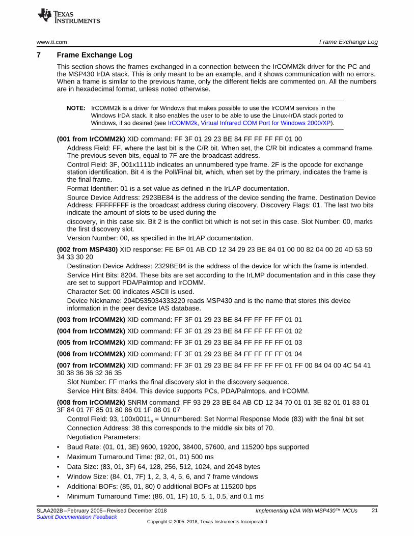
7 Frame Exchange LogThis section shows the frames exchanged in a connection between the IrCOMM2k driver for the PC andthe MSP430 IrDA stack. This is only meant to be an example, and it shows communication with no errors.When a frame is similar to the previous frame, only the different fields are commented on. All the numbersare in hexadecimal format, unless noted otherwise.
NOTE: IrCOMM2k is a driver for Windows that makes possible to use the IrCOMM services in theWindows IrDA stack. It also enables the user to be able to use the Linux-IrDA stack ported toWindows, if so desired (see IrCOMM2k, Virtual Infrared COM Port for Windows 2000/XP).
(001 from IrCOMM2k) XID command: FF 3F 01 29 23 BE 84 FF FF FF FF 01 00Address Field: FF, where the last bit is the C/R bit. When set, the C/R bit indicates a command frame.The previous seven bits, equal to 7F are the broadcast address.Control Field: 3F, 001x1111b indicates an unnumbered type frame. 2F is the opcode for exchangestation identification. Bit 4 is the Poll/Final bit, which, when set by the primary, indicates the frame isthe final frame.Format Identifier: 01 is a set value as defined in the IrLAP documentation.Source Device Address: 2923BE84 is the address of the device sending the frame. Destination DeviceAddress: FFFFFFFF is the broadcast address during discovery. Discovery Flags: 01. The last two bitsindicate the amount of slots to be used during thediscovery, in this case six. Bit 2 is the conflict bit which is not set in this case. Slot Number: 00, marksthe first discovery slot.Version Number: 00, as specified in the IrLAP documentation.
(002 from MSP430) XID response: FE BF 01 AB CD 12 34 29 23 BE 84 01 00 00 82 04 00 20 4D 53 5034 33 30 20
Destination Device Address: 2329BE84 is the address of the device for which the frame is intended.Service Hint Bits: 8204. These bits are set according to the IrLMP documentation and in this case theyare set to support PDA/Palmtop and IrCOMM.Character Set: 00 indicates ASCII is used.Device Nickname: 204D535034333220 reads MSP430 and is the name that stores this deviceinformation in the peer device IAS database.
(003 from IrCOMM2k) XID command: FF 3F 01 29 23 BE 84 FF FF FF FF 01 01
(004 from IrCOMM2k) XID command: FF 3F 01 29 23 BE 84 FF FF FF FF 01 02
(005 from IrCOMM2k) XID command: FF 3F 01 29 23 BE 84 FF FF FF FF 01 03
(006 from IrCOMM2k) XID command: FF 3F 01 29 23 BE 84 FF FF FF FF 01 04
(007 from IrCOMM2k) XID command: FF 3F 01 29 23 BE 84 FF FF FF FF 01 FF 00 84 04 00 4C 54 4130 38 36 36 32 36 35
Slot Number: FF marks the final discovery slot in the discovery sequence.Service Hint Bits: 8404. This device supports PCs, PDA/Palmtops, and IrCOMM.
(008 from IrCOMM2k) SNRM command: FF 93 29 23 BE 84 AB CD 12 34 70 01 01 3E 82 01 01 83 013F 84 01 7F 85 01 80 86 01 1F 08 01 07
Control Field: 93, 100x0011b = Unnumbered: Set Normal Response Mode (83) with the final bit setConnection Address: 38 this corresponds to the middle six bits of 70.Negotiation Parameters:
• Baud Rate: (01, 01, 3E) 9600, 19200, 38400, 57600, and 115200 bps supported• Maximum Turnaround Time: (82, 01, 01) 500 ms• Data Size: (83, 01, 3F) 64, 128, 256, 512, 1024, and 2048 bytes• Window Size: (84, 01, 7F) 1, 2, 3, 4, 5, 6, and 7 frame windows• Additional BOFs: (85, 01, 80) 0 additional BOFs at 115200 bps• Minimum Turnaround Time: (86, 01, 1F) 10, 5, 1, 0.5, and 0.1 ms
Frame Exchange Log www.ti.com
22 SLAA202B–February 2005–Revised December 2018Submit Documentation Feedback
Copyright © 2005–2018, Texas Instruments Incorporated
Implementing IrDA With MSP430™ MCUs
• Link Disconnect/Threshold Time: (08, 01, 07) 3/0, 8/3, and 12/3 seconds
(009 from MSP430) UA Response: 70 73 AB CD 12 34 23 29 BE 84 01 01 02 82 01 01 83 01 01 84 0101 85 01 01 86 01 01 08 01 01
Address Field: 70. Bit 0 is the C/R bit indicating a response, and the upper 7 bits use from now on the'Connection Address' received in the SNRM frame number 38.Control Field: 73, 011x0011b = Unnumbered: Unnumbered Acknowledgement (63) with the poll bit set.
(010 from IrCOMM2k) RR command: 71 11Address Field: 71 with the C/R bit set and the CA (connection address) set to 38.Control Field: 11 where bits 0-3 indicate a supervisory frame with a receive ready opcode, bit 4 is theP/F bit, and bits 5-7 indicate the received frame count (Nr).
(011 from MSP430) RR response: 70 11
(012 from IrCOMM2k) IrLMP Connect Command: 71 10 80 5A 01 00Control Field: 10 where bit 0 indicates an information type frame, bits 1-3 indicate the sent frame count(Ns), bit 4 is the P/F bit, and bits 5-7 indicate the received frame count.Destination: 80 where bit 7 is the control bit, and bits 0-6 are the DLSAP.Source: 5A where bit 7 is reserved, and bits 0-6 are the SLSAP.Opcode: 01 this corresponds to the connect command.Reserved: 00 for future use.
(013 from MSP430) IrLMP Connect Confirm: 70 30 DA 00 81 00Opcode: 81 corresponds to the connect confirm.
(014 from IrCOMM2k) IAS query: 71 32 00 5A 84 0B 49 72 44 41 3A 49 72 43 4F 4D 4D 0A 50 61 72 616D 65 74 65 72 73
IAP Control Field: 84 where bit 7 corresponds to the last frame bit, bit 6 is the acknowledge bit, andbits 0-5 are the opcode to the GetValueByClass IAS query.Class Name: 0B497244413A4972434F4D4D where the first byte represents the length of the classname, and the rest is the ASCII hex for the class name: "IrDA:IrCOMM"Attribute Name: 0A506172616D6574657273 where the first byte represents the length of the attribute,name and the rest is the ASCII hex for the attribute name: "Parameters".
(015 from MSP430) IAS result: 70 52 5A 00 84 00 00 01 00 01 02 00 03 00 01 07IAP Control Field: 84 where bit 7 corresponds to the last frame bit, bit 6 is the acknowledge bit, andbits 0-5 are the opcode to the GetValueByClass IAS response.Return: 00, successList Length: 01Object Identifier: 0001Type: 02 for octet sequenceSequence Length: 03Sequence: 000107, where the first byte means service type, second byte is the length of result, andthe last byte has bits set for: 3-wire raw, 3-wire, or 9-wire service.
(016 from IrCOMM2k) IrLMP Disconnect: 71 54 80 5A 02 01IrLMP opcode: 02Reason: 01 meaning user request.
(017 from MSP430) RR response: 70 71
(018 from IrCOMM2k) IrLMP Connect Command: 71 56 80 5B 01 00
(019 from MSP430) IrLMP Connect Confirm: 70 94 DB 00 81 00
(020 from IrCOMM2k) IAS query: 71 78 00 5B 84 0B 49 72 44 41 3A 49 72 43 4F 4D 4D 13 49 72 44 413A 54 69 6E 79 54 50 3A 4C 73 61 70 53 65 6C
IAP Control Field: 84 where bit 7 corresponds to the last frame bit, bit 6 is the acknowledge bit, andbits 0-5 are the opcode to the GetValueByClass IAS query.
www.ti.com Frame Exchange Log
23SLAA202B–February 2005–Revised December 2018Submit Documentation Feedback
Copyright © 2005–2018, Texas Instruments Incorporated
Implementing IrDA With MSP430™ MCUs
Class Name: 0B497244413A4972434F4D4D where the first byte represents the length of the classname, and the rest is the ASCII hex for the class name: "IrDA:IrCOMM".Attribute Name: 13497244413A54696E7954503A4C73617053656C where the first byte represents thelength of the attribute name, and the rest is the ASCII hex for the attribute name:"IrDA:TinyTP:LsapSel".
(021 from MSP430) IAS result: 70 B6 5B 00 84 00 00 01 00 01 01 00 00 00 02Type: 01 indicating an integer result.Value: 000002 indicating the LSAP to use for TTP.
(022 from IrCOMM2k) IrLMP Disconnect: 71 9A 80 5B 02 01
(023 from MSP430) RR response: 70 D1
(024 from IrCOMM2k) IrLMP/TTP Connect Command: 71 9C 82 55 01 00 10TTP Connect Frame: 10 where bit 7 is the P bit indicating a parameter-less connection frame, andwhere the remaining 7 bits indicate the Initial Credit given to the peer entity.
(025 from MSP430) IrLMP/TTP Connect Confirm: 70 F8 D5 02 81 00 01
(026 from IrCOMM2k) RR command: 71 B1
(027 from MSP430) RR response: 70 F1
(028 from IrCOMM2k) IrCOMM Parameter Set: 71 BE 02 55 00 12 00 01 04 10 04 00 00 25 80 11 01 0312 01 0C 20 01 0C
IrCOMM header: 00Length of Parameters: 12Service Type: (00, 01 04) Service selected, equal to highest service in common, 9-wireData Rate: (10, 04, 00002580) 9600 bpsData Format: (11, 01, 03) 8 bits, 1 stop bit, no parityFlow Control: (12, 01, 0C) RTS/CTS on input and outputDTE Line Settings and Changes: (20, 01, 0C) DTR and RTS state
(029 from MSP430) IrCOMM Parameter Accept and TTP credit: 70 1A 55 02 02TTP Credit: 02, where bit 7 is the M (more) bit, and the remaining six bits indicate the delta credit
(030 from IrCOMM2k) RR command: 71 D1
(031 from MSP430) RR response: 70 11
NOTE: The RR command and response and exchange continue (frames 32-37) until a device startssending.
(038 from IrCOMM2k) IrLMP PDU/IrCOMM: 71 D0 02 55 00 00 74IrCOMM data header: 0000User Data: 74, the hex value for the ASCII character t
(039 from MSP430) IrLMP PDU/IrCOMM: 70 3C 55 02 00 00 38 37 46 20IrCOMM data header: 0000User Data: 38374620, the hex sequence for the ASCII string 87F
(040 from IrCOMM2k) RR command: 71 F1
(041 from MSP430) TTP advancing credit: 70 3E 55 02 02TTP Credit: 02, where bit 7 is the M (more) bit, and the remaining six bits indicate the delta credit.
The exchange of RR command/response frames, IrCOMM user data and TTP credit continues until one ofthe peers requests disconnection after finishing the data transfer.
References www.ti.com
24 SLAA202B–February 2005–Revised December 2018Submit Documentation Feedback
Copyright © 2005–2018, Texas Instruments Incorporated
Implementing IrDA With MSP430™ MCUs
8 References1. Serial Infrared Physical Layer Specification V1.4, Infrared Data Association, 20012. Serial Infrared Link Access Protocol (IrLAP) V1.1, Infrared Data Association, IBM Corporation, Hewlett-
Packard Company, Apple Computer, Inc., Counterpoint Systems Foundry, Inc., 19963. Link Management Protocol V1.1, Infrared Data Association, 19964. Minimal IrDA Protocol Implementation (IrDA Lite) V1.0, Infrared Data Association, Counterpoint
Systems Foundry, Actisys Corporation, 19965. 'Tiny TP': A Flow Control Mechanism for use with IrLMP V1.1, Infrared Data Association, 19966. IrDA Object Exchange Protocol OBEXTM V1.3, Extended Systems, Microsoft Corporation, 20037. 'IrCOMM': Serial and Parallel Port Emulation over IR (Wire Replacement) V1.0, Counterpoint Systems
Foundry, Inc., Hewlett-Packard Company, Lexmark International, Inc., Sharp Corporation, NTTCorporation, Nokia, 1995
8. Microsoft Windows Platform SDK9. IrCOMM2k, Virtual Infrared COM Port for Windows 2000/XP10. MSP430x13x, MSP430x14x Mixed-Signal Microcontrollers11. MSP430x1xx Family User's Guide12. MSP430x2xx Family User's Guide13. MSP430x4xx Family User's Guide14. GP2W0110YPSF Low Power IrDA Transceiver Module Datasheet, Sharp Corporation, 2002
www.ti.com Revision History
25SLAA202B–February 2005–Revised December 2018Submit Documentation Feedback
Copyright © 2005–2018, Texas Instruments Incorporated
Revision History
Revision HistoryNOTE: Page numbers for previous revisions may differ from page numbers in the current version.
Changes from June 22, 2007 to December 4, 2018 ........................................................................................................ Page
• Editorial and formatting changes throughout document.............................................................................. 1

IMPORTANT NOTICE AND DISCLAIMER
TI PROVIDES TECHNICAL AND RELIABILITY DATA (INCLUDING DATASHEETS), DESIGN RESOURCES (INCLUDING REFERENCEDESIGNS), APPLICATION OR OTHER DESIGN ADVICE, WEB TOOLS, SAFETY INFORMATION, AND OTHER RESOURCES “AS IS”AND WITH ALL FAULTS, AND DISCLAIMS ALL WARRANTIES, EXPRESS AND IMPLIED, INCLUDING WITHOUT LIMITATION ANYIMPLIED WARRANTIES OF MERCHANTABILITY, FITNESS FOR A PARTICULAR PURPOSE OR NON-INFRINGEMENT OF THIRDPARTY INTELLECTUAL PROPERTY RIGHTS.These resources are intended for skilled developers designing with TI products. You are solely responsible for (1) selecting the appropriateTI products for your application, (2) designing, validating and testing your application, and (3) ensuring your application meets applicablestandards, and any other safety, security, or other requirements. These resources are subject to change without notice. TI grants youpermission to use these resources only for development of an application that uses the TI products described in the resource. Otherreproduction and display of these resources is prohibited. No license is granted to any other TI intellectual property right or to any thirdparty intellectual property right. TI disclaims responsibility for, and you will fully indemnify TI and its representatives against, any claims,damages, costs, losses, and liabilities arising out of your use of these resources.TI’s products are provided subject to TI’s Terms of Sale (www.ti.com/legal/termsofsale.html) or other applicable terms available either onti.com or provided in conjunction with such TI products. TI’s provision of these resources does not expand or otherwise alter TI’s applicablewarranties or warranty disclaimers for TI products.
Mailing Address: Texas Instruments, Post Office Box 655303, Dallas, Texas 75265Copyright © 2018, Texas Instruments Incorporated
Related Documents