Application Note Juniper Networks, Inc. 1194 North Mathilda Avenue Sunnyvale, California 94089 USA 408.745.2000 1.888 JUNIPER www.juniper.net Implementing an Auto Connect (AC) VPN Configuration on IPSec-Based VPNs Using AC VPN for Dynamic Creation of Branch-to-Branch IPsec Tunnels Part Number: 350126-001 Feb 2008

Welcome message from author
This document is posted to help you gain knowledge. Please leave a comment to let me know what you think about it! Share it to your friends and learn new things together.
Transcript
7/25/2019 Implementing an Auto Connect AC-VPN
http://slidepdf.com/reader/full/implementing-an-auto-connect-ac-vpn 1/28
Application Note
Juniper Networks, Inc.
1194 North Mathilda Avenue
Sunnyvale, California 94089
USA
408.745.2000
1.888 JUNIPER
www.juniper.net
Implementing an Auto Connect (AC) VPN
Configuration on IPSec-Based VPNs
Using AC VPN for Dynamic Creation of Branch-to-Branch
IPsec Tunnels
Part Number: 350126-001 Feb 2008

7/25/2019 Implementing an Auto Connect AC-VPN
http://slidepdf.com/reader/full/implementing-an-auto-connect-ac-vpn 2/28
Copyright ©2008, Juniper Networks, Inc.2
Implementing an Auto Connect (AC) VPN Configuration on IPSec-Based VPNs
Table of Contents
Introduction . . . . . . . . . . . . . . . . . . . . . . . . . . . . . . . . . . . . . . . . . . . . . . . . . . . . . . . . . . . . . . . . . . . . 3
Scope . . . . . . . . . . . . . . . . . . . . . . . . . . . . . . . . . . . . . . . . . . . . . . . . . . . . . . . . . . . . . . . . . . . . . . . . . 4
Protocol Operation . . . . . . . . . . . . . . . . . . . . . . . . . . . . . . . . . . . . . . . . . . . . . . . . . . . . . . . . . . . . . . . 4
Design Considerations . . . . . . . . . . . . . . . . . . . . . . . . . . . . . . . . . . . . . . . . . . . . . . . . . . . . . . . . . . . 6
Implementation . . . . . . . . . . . . . . . . . . . . . . . . . . . . . . . . . . . . . . . . . . . . . . . . . . . . . . . . . . . . . . . . . 8
Step 1. Branch Office Device Configuration . . . . . . . . . . . . . . . . . . . . . . . . . . . . . . . . . . . . . . . . . 8
Step 2. Head End Device Configuration . . . . . . . . . . . . . . . . . . . . . . . . . . . . . . . . . . . . . . . . . . . 8
Step 3. Validation . . . . . . . . . . . . . . . . . . . . . . . . . . . . . . . . . . . . . . . . . . . . . . . . . . . . . . . . . . . . 9
At the Hub . . . . . . . . . . . . . . . . . . . . . . . . . . . . . . . . . . . . . . . . . . . . . . . . . . . . . . . . . . . . . 9
At the Branch . . . . . . . . . . . . . . . . . . . . . . . . . . . . . . . . . . . . . . . . . . . . . . . . . . . . . . . . . . . . 9
Prefix Advertisement . . . . . . . . . . . . . . . . . . . . . . . . . . . . . . . . . . . . . . . . . . . . . . . . . . . . . 10
Summary . . . . . . . . . . . . . . . . . . . . . . . . . . . . . . . . . . . . . . . . . . . . . . . . . . . . . . . . . . . . . . . . . . . . . 11
Appendix 1: Branch Office Type A – Basic Profile Configuration . . . . . . . . . . . . . . . . . . . . . . . . . . 12
Appendix 2: Branch Office Type B – Optimized Profile Configuration . . . . . . . . . . . . . . . . . . . . . . 16
Appendix 3: Branch Office Type C – Critical Profile Configuration . . . . . . . . . . . . . . . . . . . . . . . . . 21
About Juniper Networks . . . . . . . . . . . . . . . . . . . . . . . . . . . . . . . . . . . . . . . . . . . . . . . . . . . . . . . . . . 27
7/25/2019 Implementing an Auto Connect AC-VPN
http://slidepdf.com/reader/full/implementing-an-auto-connect-ac-vpn 3/28
Copyright ©2008, Juniper Networks, Inc. 3
Implementing an Auto Connect (AC) VPN Configuration on IPSec-Based VPNs
Introduction
Designing and deploying network infrastructure for assured network connectivity between branch
offices and data centers presents a challenge for high-performance organizations. They must deploy
a secure and reliable enterprise network infrastructure that connects large-scale branch office
deployments to the data center using an IPSec-based VPN overlay.
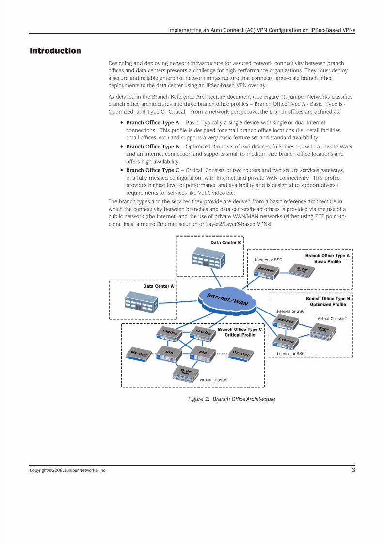
As detailed in the Branch Reference Architecture document (see Figure 1), Juniper Networks classifiesbranch office architectures into three branch office profiles – Branch Office Type A - Basic, Type B -
Optimized, and Type C - Critical. From a network perspective, the branch offices are defined as:
Branch Office Type A• – Basic: Typically a single device with single or dual Internet
connections. This profile is designed for small branch office locations (i.e., retail facilities,
small offices, etc.) and supports a very basic feature set and standard availability.
Branch Office Type B• – Optimized: Consists of two devices, fully meshed with a private WAN
and an Internet connection and supports small to medium size branch office locations and
offers high availability.
Branch Office Type C• – Critical: Consists of two routers and two secure services gateways,
in a fully meshed configuration, with Internet and private WAN connectivity. This profile
provides highest level of performance and availability and is designed to support diverse
requirements for services like VoIP, video etc.
The branch types and the services they provide are derived from a basic reference architecture in
which the connectivity between branches and data centers/head offices is provided via the use of a
public network (the Internet) and the use of private WAN/MAN networks (either using PTP point-to-
point lines, a metro Ethernet solution or Layer2/Layer3-based VPNs).
Figure 1: Branch Office Architecture
Branch Office Type A
Basic Profile
Data Center B
Data Center A
J-series or SSG
J-series or SSG
J-series or SSG
Branch Office Type B
Optimized Profile
Branch Office Type C
Critical Profile
E X 3 2 0 0 S e r i e s
Virtual Chassis™
Virtual Chassis
™
W X / W X C
W X / W X C
J - s e r i e s
J - s e r i e s
J - s e r i e s
S S G
J - s e r i e s
S S G
I n t e r n e t / W A N
E X 4 2 0 0 S e r i e s
E X 4 2 0 0 S e r i e s
E X 4 2 0 0 S e r i e s
E X 4 2 0 0 S e r i e s
J - s e r i e s
7/25/2019 Implementing an Auto Connect AC-VPN
http://slidepdf.com/reader/full/implementing-an-auto-connect-ac-vpn 4/28
Copyright ©2008, Juniper Networks, Inc.4
Implementing an Auto Connect (AC) VPN Configuration on IPSec-Based VPNs
Scope
This Application Note is designed to provide information about how to use Auto Connect VPN (AC
VPN) as part of an overall IPSec VPN network implementation. It offers configuration examples and
“how-to” information relevant to configure the branch office devices for dynamic connection using AC
VPN. A monitoring section is also included.
The Design Guide for Connectivity document captures all of the design considerations forimplementing branch office connectivity using an IPSec VPN overlay. Branch office HA designs are
detailed in the Branch Office HA Application Note.
Protocol Operation
AC VPN is a feature developed by Juniper Networks that allows the dynamic creation of branch-to-
branch IPSec tunnels. These tunnels are created on an on-demand basis and are triggered by the
traffic generated at any given branch office. To accomplish this, AC VPN makes use of the NHRP. This
protocol was originally developed for non-broadcast multiple access (NBMA) networks and intended
to provide a discovery mechanism for stations to discover the L2 address of a device connecting to a
particular L3 network (or the egress router for that particular destination).
NHRP is reused and augmented to achieve a similar task—that is, to discover the public IP addressof a VPN termination endpoint so whenever a branch office needs to send traffic to another branch
office, this office can establish an IPSec tunnel directly to the destination branch. To this effect, the
branch originating the traffic can use NHRP to discover the public IP address of the remote branch.
Some proprietary extensions have been added to the protocol and provide a way to simplify the
provisioning of these tunnels. Before presenting the details, it is important to understand the required
base topology of the network that is required for NHRP to work.
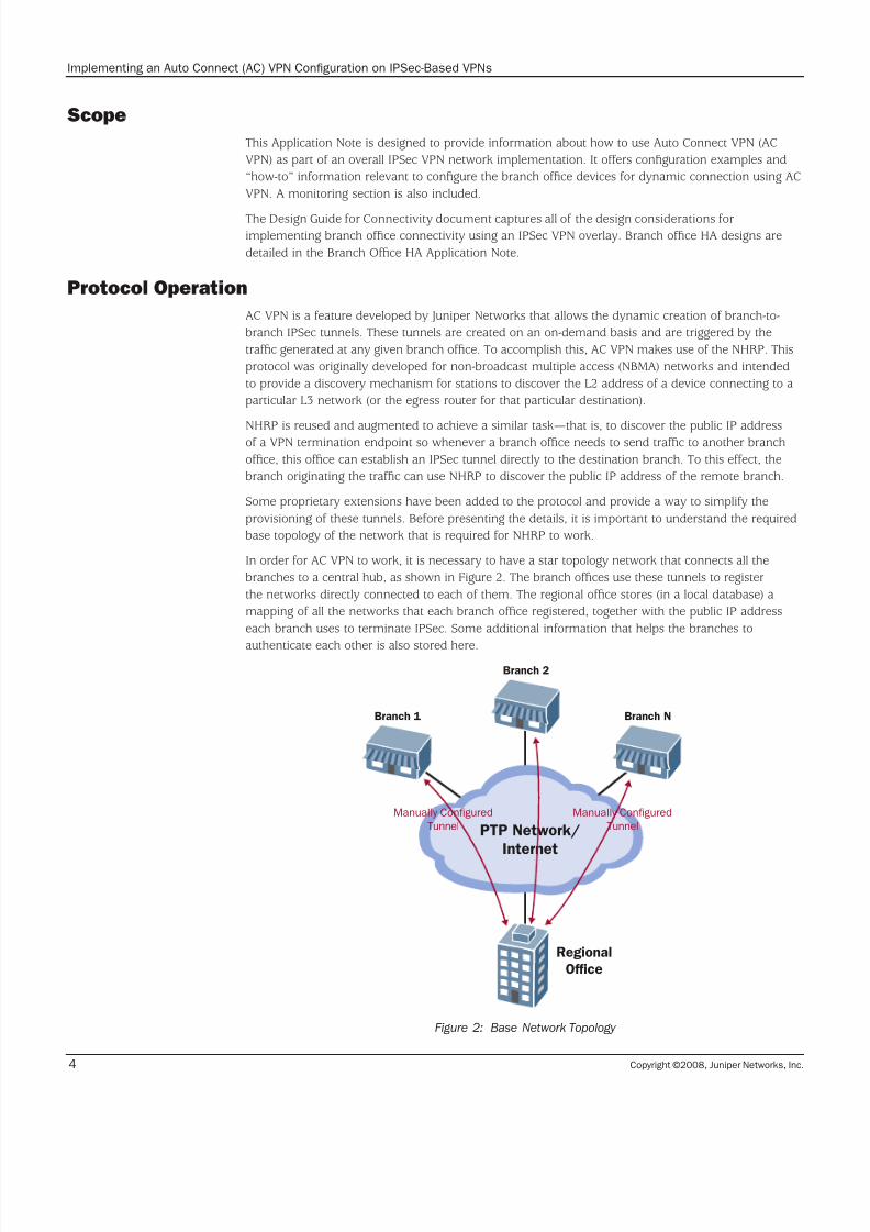
In order for AC VPN to work, it is necessary to have a star topology network that connects all the
branches to a central hub, as shown in Figure 2. The branch offices use these tunnels to register
the networks directly connected to each of them. The regional office stores (in a local database) a
mapping of all the networks that each branch office registered, together with the public IP address
each branch uses to terminate IPSec. Some additional information that helps the branches to
authenticate each other is also stored here.
Figure 2: Base Network Topology
Regional
Office
Branch 1 Branch N
Branch 2
PTP Network/
Internet
Manually Configured
Tunnel
Manually Configured
Tunnel
7/25/2019 Implementing an Auto Connect AC-VPN
http://slidepdf.com/reader/full/implementing-an-auto-connect-ac-vpn 5/28
Copyright ©2008, Juniper Networks, Inc. 5
Implementing an Auto Connect (AC) VPN Configuration on IPSec-Based VPNs
It’s important to note that the hub also stores a profile along with the configuration of the IPSec
tunnels that branch offices will use to gain connectivity. This way, the configuration is simplified, as
the tunnels only have to be configured on the hub. This configuration is then pushed to the spokes
whenever a direct IPSec VPN connection is established.
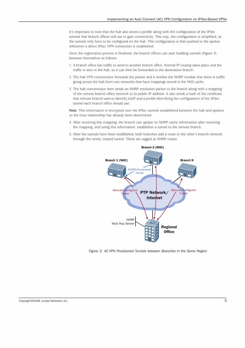
Once the registration process is finalized, the branch offices can start building tunnels (Figure 3)
between themselves as follows:
1. A branch office has traffic to send to another branch office. Normal IP routing takes place and the
traffic is sent to the hub, so it can then be forwarded to the destination branch.
2. The hub VPN concentrator forwards the packet and it notifies the NHRP module that there is traffic
going across the hub from two networks that have mappings stored in the NHS cache.
3. The hub concentrator then sends an NHRP resolution packet to the branch along with a mapping
of the remote branch office network to its public IP address. It also sends a hash of the certificate
that remote branch uses to identify itself and a profile describing the configuration of the IPSec
tunnel each branch office should use.
Note: This information is encrypted over the IPSec tunnels (established between the hub and spokes)
so the trust relationship has already been determined.
4. After receiving this mapping, the branch can update its NHRP cache information after receivingthe mapping, and using this information, establishes a tunnel to the remote branch.
5. After the tunnels have been established, both branches add a route to the other’s branch network
through the newly created tunnel. These are tagged as NHRP routes.
Figure 3: AC VPN Provisioned Tunnels between Branches in the Same Region
Regional
Office
Branch 1 (NHC)
NHRP
Next Hop Server
Branch N
Branch 2 (NHC)
PTP Network/
Internet
Manually Configured
TunnelManually Configured
Tunnel
ACVPN Provisioned
Tunnel

7/25/2019 Implementing an Auto Connect AC-VPN
http://slidepdf.com/reader/full/implementing-an-auto-connect-ac-vpn 6/28
Copyright ©2008, Juniper Networks, Inc.6
Implementing an Auto Connect (AC) VPN Configuration on IPSec-Based VPNs
Design Considerations
The following are the design considerations and assumptions associated with this implementation:
The Next Hop Server (NHS) address must be the address of the tunnel interface terminating•
the IPSec tunnels from the branch offices. In particular, the NHS will not detect requests on
loopback interfaces.
A device can only act as a Next Hop Client (NHC) or an NHS but not both. That is, hierarchies•
are not supported.
On Type B - Optimized branch offices, no AC VPN is provided for the secondary device. That•
is, in the event of a failure, the AC VPN service will not be available and traffic will be routed
through the hub.
When using Active/Active NetScreen Redundancy Protocol (NSRP), neither the Security•
Associations (SAs) nor the Next Hop Resolution Protocol (NHRP) caches will be synchronized.
In the event of a failover, a new NHRP registration will be performed, and branch-to-branch
tunnels will have to be reestablished. This will not, however, have an impact on branch-to-
branch traffic, as this traffic will still be routed through the hub.
Branch offices only that are connected to the same hub (that is, a data center or regional•
office) can establish IPSec shortcuts between themselves. When branches are not connected
to the same regional office/data center, traffic flows using the preexisting topology.
AC VPN only establishes shortcuts between branch offices connected to the same hub for•
multi-tier topologies. In a network like the one shown in Figure 4, only branch offices in
the same region will be able to establish shortcuts. However, traffic between branch offices
can still use normal routing and go through the different hubs until it reaches the desired
destination.

7/25/2019 Implementing an Auto Connect AC-VPN
http://slidepdf.com/reader/full/implementing-an-auto-connect-ac-vpn 7/28
Copyright ©2008, Juniper Networks, Inc. 7
Implementing an Auto Connect (AC) VPN Configuration on IPSec-Based VPNs
Figure 4: Multi-Tier Topology
One NHS server only can be configured on a per-client basis. In the event of a complete failure•
on the hub (either data center or regional office acting as an NHS), branch offices will not be
able to establish shortcuts until connectivity to the hub is restored.
A new registration to the NHS will be required when an NSRP failover is triggered. If a failover•
occurs at one of the hubs, then every branch office will have to reregister and the NHRP cache
will have to be repopulated.
NHRP is not supported over unnumbered interfaces.•
Regional
Office
Data
Center B
Data
Center A
Branch 1 Branch N
Branch Branch Branch Branch Branch
Branch 2
PTP Network/
Internet
PTP Network/Internet
IPSec
Tunnel
IPSec
Tunnel
IPSec Tunnel
or PTP Connection
IPSec Tunnel
or PTP Connection
IPSec Tunnel
or PTP Connection
IPSec
Tunnel
IPSec
Tunnel
IPSec
Tunnel
IPSec
Tunnel
IPSec
Tunnel
7/25/2019 Implementing an Auto Connect AC-VPN
http://slidepdf.com/reader/full/implementing-an-auto-connect-ac-vpn 8/28
Copyright ©2008, Juniper Networks, Inc.8
Implementing an Auto Connect (AC) VPN Configuration on IPSec-Based VPNs
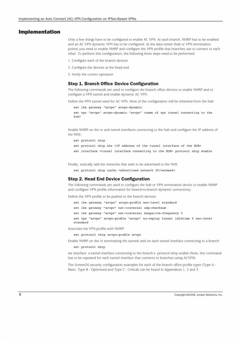
Implementation
Only a few things have to be configured to enable AC VPN. At each branch, NHRP has to be enabled
and an AC VPN dynamic VPN has to be configured. At the data center (hub or VPN termination
points) you need to enable NHRP and configure the VPN profile that branches use to connect to each
other. To perform this configuration, the following three steps need to be performed:
1. Configure each of the branch devices
2. Configure the devices at the head end
3. Verify the correct operation
Step 1. Branch Office Device Configuration
The following commands are used to configure the branch office devices to enable NHRP and to
configure a VPN tunnel and enable dynamic AC VPN.
Define the FPN tunnel used for AC VPN. Most of the configuration will be inherited from the hub:
set ike gateway “acvpn” acvpn-dynamic
set vpn “acvpn” acvpn-dynamic “acvpn” <name of vpn tunnel connecting to the
hub>
Enable NHRP on the vr and tunnel interfaces connecting to the hub and configure the IP address of
the NHS:
set protocol nhrp
set protocol nhrp nhs <IP address of the tunnel interface of the HUB>
set interface <tunnel interface connecting to the HUB> protocol nhrp enable
Finally, statically add the networks that seek to be advertised to the NHS:
set protocol nhrp cache <advertised network IP/netmask>
Step 2. Head End Device ConfigurationThe following commands are used to configure the hub or VPN termination device to enable NHRP
and configure VPN profile information for branch-to-branch dynamic connectivity.
Define the VPN profile to be pushed to the branch devices:
set ike gateway “acvpn” acvpn-prole sec-level standard
set ike gateway “acvpn” nat-traversal udp-checksum
set ike gateway “acvpn” nat-traversal keepalive-frequency 5
set vpn “acvpn” acvpn-prole “acvpn” no-replay tunnel idletime 0 sec-level
standard
Associate the VPN profile with NHRP:
set protocol nhrp acvpn-prole acvpn
Enable NHRP on the vr terminating the tunnels and on each tunnel interface connecting to a branch:
set protocol nhrp
set interface <tunnel interface connecting to the branch> protocol nhrp enable (Note, this command
has to be repeated for each tunnel interface that connects to branches using ACVPN)
The ScreenOS security configuration examples for each of the branch office profile types (Type A -
Basic, Type B - Optimized and Type C - Critical) can be found in Appendices 1, 2 and 3.
7/25/2019 Implementing an Auto Connect AC-VPN
http://slidepdf.com/reader/full/implementing-an-auto-connect-ac-vpn 9/28
Copyright ©2008, Juniper Networks, Inc. 9
Implementing an Auto Connect (AC) VPN Configuration on IPSec-Based VPNs
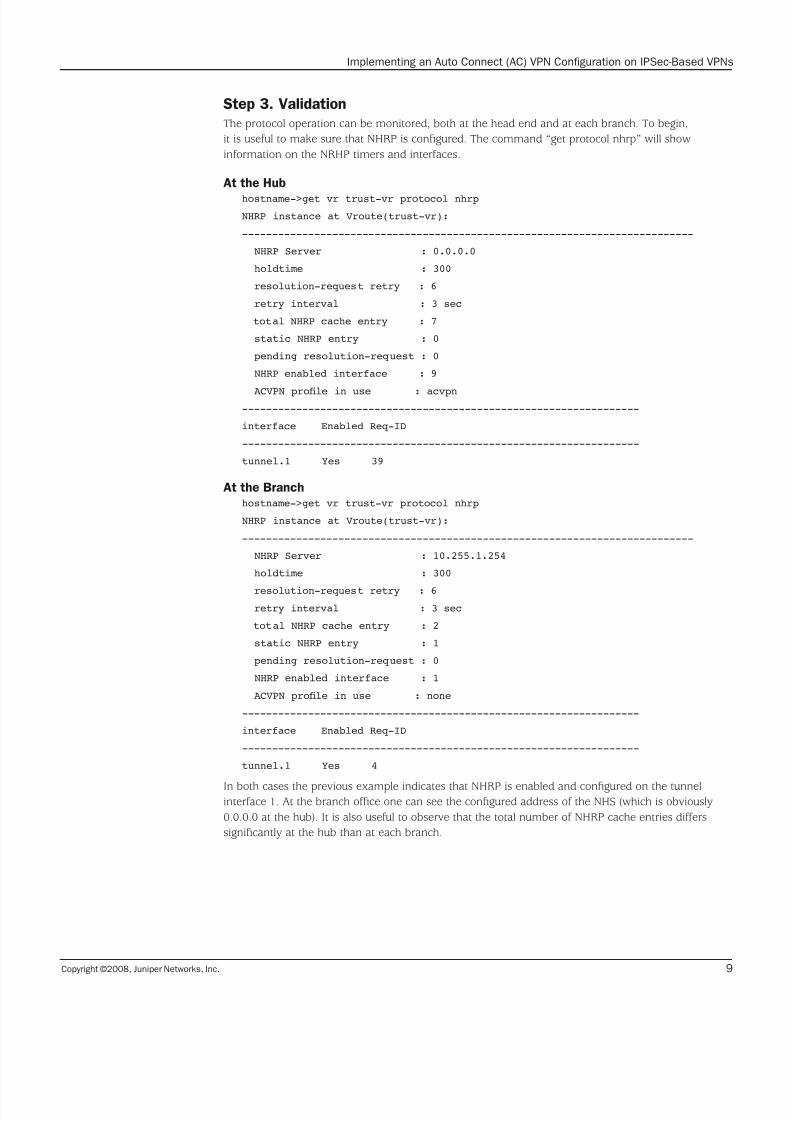
Step 3. Validation
The protocol operation can be monitored, both at the head end and at each branch. To begin,
it is useful to make sure that NHRP is configured. The command “get protocol nhrp” will show
information on the NRHP timers and interfaces.
At the Hub
hostname->get vr trust-vr protocol nhrp
NHRP instance at Vroute(trust-vr):
---------------------------------------------------------------------------
NHRP Server : 0.0.0.0
holdtime : 300
resolution-request retry : 6
retry interval : 3 sec
total NHRP cache entry : 7
static NHRP entry : 0
pending resolution-request : 0
NHRP enabled interface : 9
ACVPN prole in use : acvpn------------------------------------------------------------------
interface Enabled Req-ID
------------------------------------------------------------------
tunnel.1 Yes 39
At the Branch
hostname->get vr trust-vr protocol nhrp
NHRP instance at Vroute(trust-vr):
---------------------------------------------------------------------------
NHRP Server : 10.255.1.254
holdtime : 300
resolution-request retry : 6
retry interval : 3 sec
total NHRP cache entry : 2
static NHRP entry : 1
pending resolution-request : 0
NHRP enabled interface : 1
ACVPN prole in use : none
------------------------------------------------------------------
interface Enabled Req-ID
------------------------------------------------------------------
tunnel.1 Yes 4
In both cases the previous example indicates that NHRP is enabled and configured on the tunnelinterface 1. At the branch office one can see the configured address of the NHS (which is obviously
0.0.0.0 at the hub). It is also useful to observe that the total number of NHRP cache entries differs
significantly at the hub than at each branch.
7/25/2019 Implementing an Auto Connect AC-VPN
http://slidepdf.com/reader/full/implementing-an-auto-connect-ac-vpn 10/28
Copyright ©2008, Juniper Networks, Inc.10
Implementing an Auto Connect (AC) VPN Configuration on IPSec-Based VPNs
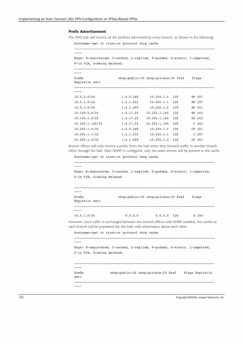
Prefix Advertisement
The NHS hub will receive all the prefixes advertised by every branch, as shown in the following:
hostname->get vr trust-vr protocol nhrp cache
----------------------------------------------------------------------------
----
ags: R-registered, C-cached, L-replied, P-pushed, S-static, I-imported,
F-in FIB, D-being deleted.
----------------------------------------------------------------------------
----
Prex nhop-public-IP nhop-private-IP Pref Flags
Expire(in sec)
----------------------------------------------------------------------------
----
10.5.5.0/24 1.4.0.248 10.255.1.5 128 RF 201
10.5.1.0/24 1.2.1.252 10.255.1.1 128 RF 297
10.5.3.0/24 1.2.1.249 10.255.1.2 128 RF 201
10.140.0.0/24 1.4.17.24 10.255.1.140 128 RF 243
10.140.1.0/25 1.4.17.24 10.255.1.140 128 RF 243
10.255.1.140/32 1.4.17.24 10.255.1.140 128 C 243
10.255.1.5/32 1.4.0.248 10.255.1.5 128 CF 201
10.255.1.1/32 1.2.1.252 10.255.1.1 128 C 297
10.255.1.2/32 1.2.1.249 10.255.1.2 128 CF 201
Branch offices will only receive a prefix from the hub when they forward traffic to another branch
office through the hub. After NHRP is configured, only the static entries will be present in the cache.
hostname->get vr trust-vr protocol nhrp cache
----------------------------------------------------------------------------
----
ags: R-registered, C-cached, L-replied, P-pushed, S-static, I-imported,
F-in FIB, D-being deleted.
----------------------------------------------------------------------------
----
Prex nhop-public-IP nhop-private-IP Pref Flags
Expire(in sec)
----------------------------------------------------------------------------
----
10.5.1.0/24 0.0.0.0 0.0.0.0 128 S 300
However, once traffic is exchanged between two branch offices with NHRP enabled, the caches at
each branch will be populated (by the hub) with information about each other.
hostname->get vr trust-vr protocol nhrp cache
----------------------------------------------------------------------------
----
ags: R-registered, C-cached, L-replied, P-pushed, S-static, I-imported,
F-in FIB, D-being deleted.
----------------------------------------------------------------------------
----
Prex nhop-public-IP nhop-private-IP Pref Flags Expire(in
sec)
----------------------------------------------------------------------------
----

7/25/2019 Implementing an Auto Connect AC-VPN
http://slidepdf.com/reader/full/implementing-an-auto-connect-ac-vpn 11/28
Copyright ©2008, Juniper Networks, Inc. 11
Implementing an Auto Connect (AC) VPN Configuration on IPSec-Based VPNs
10.5.1.0/24 0.0.0.0 0.0.0.0 128 S 300
10.5.3.0/24 1.2.1.249 0.0.0.0 0 P 213
NHRP will also send information to the branches about the certificates used by each peer for IPSec
authentication. This information can be seen viewed with the “get nhrp peer” command.
hostname->get vr trust-vr protocol nhrp peer
--------------------------------------------------------------------------------
Learned peers (Total = 1):
----------------------------------------------------------------------------
----
Peer nhop prot Self-cert-hash ID type ID
--------------- ---------------------------------------------- -------
---------------
10.255.1.2 <7d67c074 4a417b24 c0bab634 ae1c86fc fc8f6313> 9
CN=0168102006001372,CN=system generated,CN=self-signed
Summary
The use of AC VPN allows the dynamic creation of branch-to-branch IPSec tunnels to efficiently
communicate between branch offices connected to the same regional office or data center. NHRP
is used to discover the public IP address of a VPN termination endpoint. Whenever a branch office
needs to send traffic to another branch office, the source branch establishes an IPSec tunnel directly
to the destination branch and that tunnel is designated as an NHRP route.
7/25/2019 Implementing an Auto Connect AC-VPN
http://slidepdf.com/reader/full/implementing-an-auto-connect-ac-vpn 12/28
Copyright ©2008, Juniper Networks, Inc.12
Implementing an Auto Connect (AC) VPN Configuration on IPSec-Based VPNs
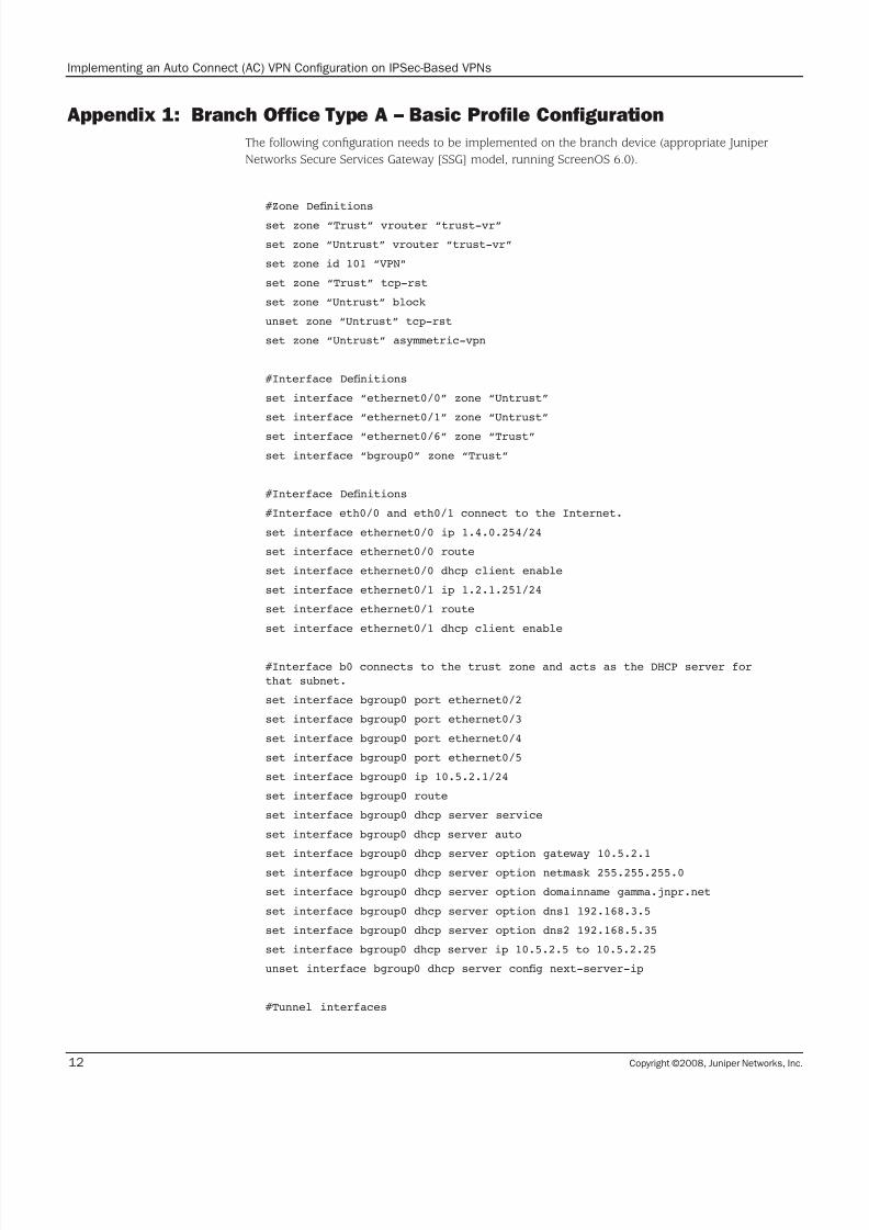
Appendix 1: Branch Office Type A – Basic Profile Configuration
The following configuration needs to be implemented on the branch device (appropriate Juniper
Networks Secure Services Gateway [SSG] model, running ScreenOS 6.0).
#Zone Denitions
set zone “Trust” vrouter “trust-vr”
set zone “Untrust” vrouter “trust-vr”
set zone id 101 “VPN”
set zone “Trust” tcp-rst
set zone “Untrust” block
unset zone “Untrust” tcp-rst
set zone “Untrust” asymmetric-vpn
#Interface Denitions
set interface “ethernet0/0” zone “Untrust”
set interface “ethernet0/1” zone “Untrust”
set interface “ethernet0/6” zone “Trust”
set interface “bgroup0” zone “Trust”
#Interface Denitions
#Interface eth0/0 and eth0/1 connect to the Internet.
set interface ethernet0/0 ip 1.4.0.254/24
set interface ethernet0/0 route
set interface ethernet0/0 dhcp client enable
set interface ethernet0/1 ip 1.2.1.251/24
set interface ethernet0/1 route
set interface ethernet0/1 dhcp client enable
#Interface b0 connects to the trust zone and acts as the DHCP server for
that subnet.
set interface bgroup0 port ethernet0/2
set interface bgroup0 port ethernet0/3
set interface bgroup0 port ethernet0/4
set interface bgroup0 port ethernet0/5
set interface bgroup0 ip 10.5.2.1/24
set interface bgroup0 route
set interface bgroup0 dhcp server service
set interface bgroup0 dhcp server auto
set interface bgroup0 dhcp server option gateway 10.5.2.1
set interface bgroup0 dhcp server option netmask 255.255.255.0
set interface bgroup0 dhcp server option domainname gamma.jnpr.net
set interface bgroup0 dhcp server option dns1 192.168.3.5
set interface bgroup0 dhcp server option dns2 192.168.5.35
set interface bgroup0 dhcp server ip 10.5.2.5 to 10.5.2.25
unset interface bgroup0 dhcp server cong next-server-ip
#Tunnel interfaces
7/25/2019 Implementing an Auto Connect AC-VPN
http://slidepdf.com/reader/full/implementing-an-auto-connect-ac-vpn 13/28
Copyright ©2008, Juniper Networks, Inc. 13
Implementing an Auto Connect (AC) VPN Configuration on IPSec-Based VPNs
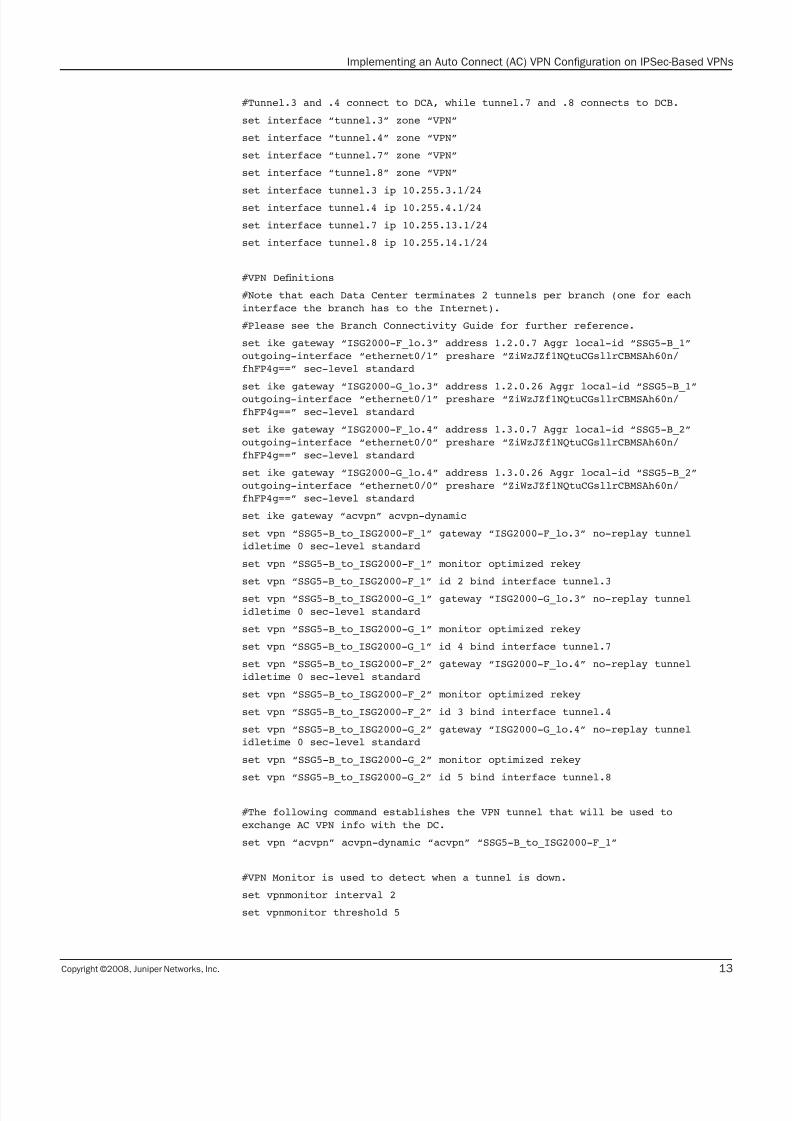
#Tunnel.3 and .4 connect to DCA, while tunnel.7 and .8 connects to DCB.
set interface “tunnel.3” zone “VPN”
set interface “tunnel.4” zone “VPN”
set interface “tunnel.7” zone “VPN”
set interface “tunnel.8” zone “VPN”
set interface tunnel.3 ip 10.255.3.1/24
set interface tunnel.4 ip 10.255.4.1/24
set interface tunnel.7 ip 10.255.13.1/24
set interface tunnel.8 ip 10.255.14.1/24
#VPN Denitions
#Note that each Data Center terminates 2 tunnels per branch (one for each
interface the branch has to the Internet).
#Please see the Branch Connectivity Guide for further reference.
set ike gateway “ISG2000-F_lo.3” address 1.2.0.7 Aggr local-id “SSG5-B_1”
outgoing-interface “ethernet0/1” preshare “ZiWzJZf1NQtuCGsllrCBMSAh60n/
fhFP4g==” sec-level standard
set ike gateway “ISG2000-G_lo.3” address 1.2.0.26 Aggr local-id “SSG5-B_1”
outgoing-interface “ethernet0/1” preshare “ZiWzJZf1NQtuCGsllrCBMSAh60n/
fhFP4g==” sec-level standard
set ike gateway “ISG2000-F_lo.4” address 1.3.0.7 Aggr local-id “SSG5-B_2”
outgoing-interface “ethernet0/0” preshare “ZiWzJZf1NQtuCGsllrCBMSAh60n/
fhFP4g==” sec-level standard
set ike gateway “ISG2000-G_lo.4” address 1.3.0.26 Aggr local-id “SSG5-B_2”
outgoing-interface “ethernet0/0” preshare “ZiWzJZf1NQtuCGsllrCBMSAh60n/
fhFP4g==” sec-level standard
set ike gateway “acvpn” acvpn-dynamic
set vpn “SSG5-B_to_ISG2000-F_1” gateway “ISG2000-F_lo.3” no-replay tunnel
idletime 0 sec-level standard
set vpn “SSG5-B_to_ISG2000-F_1” monitor optimized rekey
set vpn “SSG5-B_to_ISG2000-F_1” id 2 bind interface tunnel.3
set vpn “SSG5-B_to_ISG2000-G_1” gateway “ISG2000-G_lo.3” no-replay tunnel
idletime 0 sec-level standard
set vpn “SSG5-B_to_ISG2000-G_1” monitor optimized rekey
set vpn “SSG5-B_to_ISG2000-G_1” id 4 bind interface tunnel.7
set vpn “SSG5-B_to_ISG2000-F_2” gateway “ISG2000-F_lo.4” no-replay tunnel
idletime 0 sec-level standard
set vpn “SSG5-B_to_ISG2000-F_2” monitor optimized rekey
set vpn “SSG5-B_to_ISG2000-F_2” id 3 bind interface tunnel.4
set vpn “SSG5-B_to_ISG2000-G_2” gateway “ISG2000-G_lo.4” no-replay tunnel
idletime 0 sec-level standard
set vpn “SSG5-B_to_ISG2000-G_2” monitor optimized rekey
set vpn “SSG5-B_to_ISG2000-G_2” id 5 bind interface tunnel.8
#The following command establishes the VPN tunnel that will be used to
exchange AC VPN info with the DC.
set vpn “acvpn” acvpn-dynamic “acvpn” “SSG5-B_to_ISG2000-F_1”
#VPN Monitor is used to detect when a tunnel is down.
set vpnmonitor interval 2
set vpnmonitor threshold 5

7/25/2019 Implementing an Auto Connect AC-VPN
http://slidepdf.com/reader/full/implementing-an-auto-connect-ac-vpn 14/28
Copyright ©2008, Juniper Networks, Inc.14
Implementing an Auto Connect (AC) VPN Configuration on IPSec-Based VPNs
set vrouter “trust-vr”
unset auto-route-export
set max-ecmp-routes 4
#NHRP protocol
#Note that the NHS server address is the address of the tunnel interface atthe remote end of the IPSec tunnel, connecting to the DC.
#We also have to manually declare the networks we want to advertise to the
NHS.
set protocol nhrp
set protocol nhrp nhs 10.255.3.254
set protocol nhrp cache 10.5.2.0/24
#The static routes force traic to use a dierent interface for each tunnel
to each of the Data Centers.
unset add-default-route
set route 1.2.0.0/29 interface ethernet0/1
set route 1.3.0.0/29 interface ethernet0/0
#Route maps are used to lter the routes advertised by this branch and
received from the Data Centers.
set access-list 1
set access-list 1 permit ip 172.18.0.0/16 1
set access-list 1 permit ip 192.168.4.0/24 2
set access-list 1 permit ip 192.168.5.0/24 3
set access-list 1 deny ip 10.128.0.0/9 8
set access-list 1 deny ip 10.0.0.0/9 9
set access-list 1 permit ip 10.0.0.0/8 10
set access-list 2
set access-list 2 permit ip 10.5.0.0/16 1
set route-map name “acceptDC” permit 1
set match ip 1
exit
set route-map name “localNetworks” permit 1
set match ip 2
exit
#RIP is used to exchange routes with the VPN concentrators at the DCs.
set protocol rip
set enable
set default-metric 1
set reject-default-route
set no-source-validation
set alt-route 3
set redistribute route-map “localNetworks” protocol connected
set route-map “acceptDC” in
set route-map “localNetworks” out
exit
exit

7/25/2019 Implementing an Auto Connect AC-VPN
http://slidepdf.com/reader/full/implementing-an-auto-connect-ac-vpn 15/28
Copyright ©2008, Juniper Networks, Inc. 15
Implementing an Auto Connect (AC) VPN Configuration on IPSec-Based VPNs
#NHRP has to be enabled on the tunnel interface connecting to the DC. This
MUST be a numbered interface.
set interface tunnel.3 protocol nhrp enable
#RIP using on-demand circuit extensions has to be enabled on the tunnel
interfaces for the RIP exchange to take place.
set interface tunnel.3 protocol rip
set interface tunnel.3 protocol rip enable
set interface tunnel.3 protocol rip metric 2
set interface tunnel.3 protocol rip demand-circuit
set interface bgroup0 protocol rip
set interface bgroup0 protocol rip enable
set interface bgroup0 protocol rip passive-mode
set interface tunnel.4 protocol rip
set interface tunnel.4 protocol rip enable
set interface tunnel.4 protocol rip metric 2
set interface tunnel.4 protocol rip demand-circuitset interface tunnel.7 protocol rip
set interface tunnel.7 protocol rip enable
set interface tunnel.7 protocol rip metric 2
set interface tunnel.7 protocol rip demand-circuit
set interface tunnel.8 protocol rip
set interface tunnel.8 protocol rip enable
set interface tunnel.8 protocol rip metric 2
set interface tunnel.8 protocol rip demand-circuit
7/25/2019 Implementing an Auto Connect AC-VPN
http://slidepdf.com/reader/full/implementing-an-auto-connect-ac-vpn 16/28
Copyright ©2008, Juniper Networks, Inc.16
Implementing an Auto Connect (AC) VPN Configuration on IPSec-Based VPNs
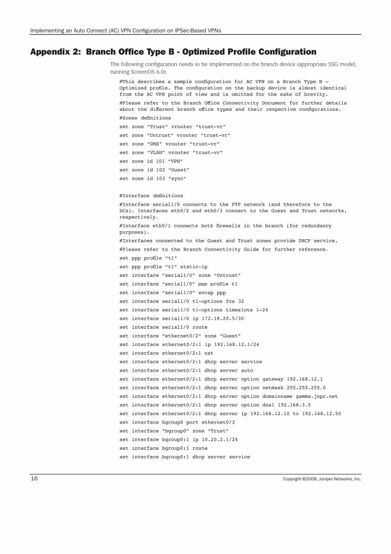
Appendix 2: Branch Office Type B - Optimized Profile Configuration
The following configuration needs to be implemented on the branch device (appropriate SSG model,
running ScreenOS 6.0).
#This describes a sample conguration for AC VPN on a Branch Type B –
Optimized prole. The conguration on the backup device is almost identical
from the AC VPN point of view and is omitted for the sake of brevity.
#Please refer to the Branch Oice Connectivity Document for further details
about the dierent branch oice types and their respective congurations.
#Zones denitions
set zone “Trust” vrouter “trust-vr”
set zone “Untrust” vrouter “trust-vr”
set zone “DMZ” vrouter “trust-vr”
set zone “VLAN” vrouter “trust-vr”
set zone id 101 “VPN”
set zone id 102 “Guest”
set zone id 103 “sync”
#Interface denitions
#Interface serial1/0 connects to the PTP network (and therefore to the
DCs). Interfaces eth0/2 and eth0/3 connect to the Guest and Trust networks,
respectively.
#Interface eth0/1 connects both rewalls in the branch (for redundancy
purposes).
#Interfaces connected to the Guest and Trust zones provide DHCP service.
#Please refer to the Branch Connectivity Guide for further reference.
set ppp prole “t1”
set ppp prole “t1” static-ip
set interface “serial1/0” zone “Untrust”
set interface “serial1/0” ppp prole t1
set interface “serial1/0” encap ppp
set interface serial1/0 t1-options fcs 32
set interface serial1/0 t1-options timeslots 1-24
set interface serial1/0 ip 172.18.20.5/30
set interface serial1/0 route
set interface “ethernet0/2” zone “Guest”
set interface ethernet0/2:1 ip 192.168.12.1/24
set interface ethernet0/2:1 nat
set interface ethernet0/2:1 dhcp server service
set interface ethernet0/2:1 dhcp server auto
set interface ethernet0/2:1 dhcp server option gateway 192.168.12.1
set interface ethernet0/2:1 dhcp server option netmask 255.255.255.0set interface ethernet0/2:1 dhcp server option domainname gamma.jnpr.net
set interface ethernet0/2:1 dhcp server option dns1 192.168.3.5
set interface ethernet0/2:1 dhcp server ip 192.168.12.10 to 192.168.12.50
set interface bgroup0 port ethernet0/3
set interface “bgroup0” zone “Trust”
set interface bgroup0:1 ip 10.20.2.1/24
set interface bgroup0:1 route
set interface bgroup0:1 dhcp server service
7/25/2019 Implementing an Auto Connect AC-VPN
http://slidepdf.com/reader/full/implementing-an-auto-connect-ac-vpn 17/28
Copyright ©2008, Juniper Networks, Inc. 17
Implementing an Auto Connect (AC) VPN Configuration on IPSec-Based VPNs
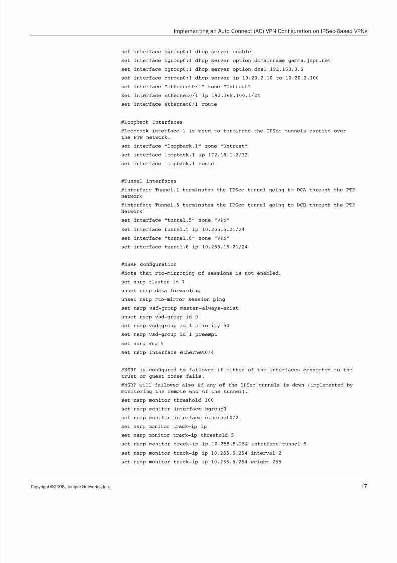
set interface bgroup0:1 dhcp server enable
set interface bgroup0:1 dhcp server option domainname gamma.jnpr.net
set interface bgroup0:1 dhcp server option dns1 192.168.3.5
set interface bgroup0:1 dhcp server ip 10.20.2.10 to 10.20.2.100
set interface “ethernet0/1” zone “Untrust”
set interface ethernet0/1 ip 192.168.100.1/24
set interface ethernet0/1 route
#Loopback Interfaces
#Loopback interface 1 is used to terminate the IPSec tunnels carried over
the PTP network.
set interface “loopback.1” zone “Untrust”
set interface loopback.1 ip 172.18.1.2/32
set interface loopback.1 route
#Tunnel interfaces
#interface Tunnel.1 terminates the IPSec tunnel going to DCA through the PTP
Network#interface Tunnel.5 terminates the IPSec tunnel going to DCB through the PTP
Network
set interface “tunnel.5” zone “VPN”
set interface tunnel.5 ip 10.255.5.21/24
set interface “tunnel.8” zone “VPN”
set interface tunnel.8 ip 10.255.15.21/24
#NSRP conguration
#Note that rto-mirroring of sessions is not enabled.
set nsrp cluster id 7
unset nsrp data-forwarding
unset nsrp rto-mirror session ping
set nsrp vsd-group master-always-exist
unset nsrp vsd-group id 0
set nsrp vsd-group id 1 priority 50
set nsrp vsd-group id 1 preempt
set nsrp arp 5
set nsrp interface ethernet0/4
#NSRP is congured to failover if either of the interfaces connected to the
trust or guest zones fails.
#NSRP will failover also if any of the IPSec tunnels is down (implemented by
monitoring the remote end of the tunnel).
set nsrp monitor threshold 100
set nsrp monitor interface bgroup0
set nsrp monitor interface ethernet0/2
set nsrp monitor track-ip ip
set nsrp monitor track-ip threshold 5
set nsrp monitor track-ip ip 10.255.5.254 interface tunnel.5
set nsrp monitor track-ip ip 10.255.5.254 interval 2
set nsrp monitor track-ip ip 10.255.5.254 weight 255

7/25/2019 Implementing an Auto Connect AC-VPN
http://slidepdf.com/reader/full/implementing-an-auto-connect-ac-vpn 18/28
Copyright ©2008, Juniper Networks, Inc.18
Implementing an Auto Connect (AC) VPN Configuration on IPSec-Based VPNs
set nsrp monitor track-ip ip 10.255.15.254 interface tunnel.8
set nsrp monitor track-ip ip 10.255.15.254 interval 2
set nsrp monitor track-ip ip 10.255.15.254 weight 255
set nsrp ha-link probe
unset nsrp cong sync
#Flow conguration.
#Adjusting the TCP-MSS performed to avoid fragmentation, and allow packets
that fail the RPF check on the tunnel interface to be forwarded (this should
only be the case while routing is converging, after a topology change).
#In the event of a failover, established sessions on the primary device will
be created on the backup device as traic is diverted to the backup. NSRP
session sync is not enabled but the devices are congured to not perform
tcp-syn-check on VPN packets, which means that any packet (not only syn
packets) can create sessions.
set ow tcp-mss 1400
set ow tcp-syn-check
unset ow tcp-syn-check-in-tunnel
set ow x-tunnel-out-ifset ow reverse-route tunnel prefer
#VPN Monitor is used to detect when a tunnel is down.
set vpnmonitor interval 2
set vpnmonitor threshold 5
#IPSec Conguration. There is one tunnel congured to each DC.
set ike gateway “ISG2000-E_lo.5:1” address 172.18.8.162 Main outgoing-
interface “loopback.1” preshare “gNgxAuzNNj6I6BsxdsCSOY/65FnESx3eaA==” sec-
level standard
set ike gateway “ISG2000-G_lo.5:1” address 172.18.16.162 Main outgoing-
interface “loopback.1” preshare “gNgxAuzNNj6I6BsxdsCSOY/65FnESx3eaA==” sec-level standard
set vpn “SSG20-C_to_ISG2000-E_1” gateway “ISG2000-E_lo.5:1” no-replay tunnel
idletime 0 sec-level standard
set vpn “SSG20-C_to_ISG2000-E_1” monitor optimized rekey
set vpn “SSG20-C_to_ISG2000-E_1” id 1 bind interface tunnel.5
set vpn “SSG20-C_to_ISG2000-G_1” gateway “ISG2000-G_lo.5:1” no-replay tunnel
idletime 0 sec-level standard
set vpn “SSG20-C_to_ISG2000-G_1” monitor optimized rekey
set vpn “SSG20-C_to_ISG2000-G_1” id 2 bind interface tunnel.8
#This gateway declaration serves as a placeholder for the IKE gateway
conguration that is received from the NHS when a shortcut is pushed to the
device.
set ike gateway “acvpn” acvpn-dynamic
#The following command establishes the VPN tunnel that will be used to
exchange AC VPN info with the DC.
set vpn “acvpn” acvpn-dynamic “acvpn” “SSG20-C_to_ISG2000-E_1”
set vrouter “trust-vr”
set max-ecmp-routes 4
unset auto-route-export

7/25/2019 Implementing an Auto Connect AC-VPN
http://slidepdf.com/reader/full/implementing-an-auto-connect-ac-vpn 19/28
Copyright ©2008, Juniper Networks, Inc. 19
Implementing an Auto Connect (AC) VPN Configuration on IPSec-Based VPNs
#Route maps are used to lter the routes advertised by this branch and
received from the Data Centers.
set access-list 1
set access-list 1 permit ip 172.18.0.0/16 1
set access-list 1 permit ip 192.168.4.0/24 2
set access-list 1 permit ip 192.168.5.0/24 3
set access-list 1 deny ip 10.128.0.0/9 8
set access-list 1 deny ip 10.0.0.0/9 9
set access-list 1 permit ip 10.0.0.0/8 10
set access-list 1 permit default-route 11
set access-list 2
set access-list 2 permit ip 10.20.0.0/16 1
set access-list 3
set access-list 3 permit ip 0.0.0.0/0 1
set route-map name “remoteNetworks” permit 1
set match ip 1
exit
set route-map name “localNetworks” permit 1
set match ip 2
exit
set route-map name “rejectAll” deny 1
set match ip 3
exit
#NHRP protocol
#Note that the NHS server address is the address of the tunnel interface at
the remote end of the IPSec tunnel, connecting to the DC.
#We also have to manually declare the networks we want to advertise to the
NH.
set protocol nhrp
set protocol nhrp nhs 10.255.5.254
set protocol nhrp cache 10.20.2.0/24
set protocol bgp 65100
unset synchronization
set reject-default-route
set neighbor 172.31.254.15 remote-as 65100 outgoing-interface loopback.10
set neighbor 172.31.254.15 enable
set neighbor 172.31.254.15 send-community
set neighbor 172.31.254.15 nhself-enable
set neighbor 172.31.255.15 remote-as 65100 outgoing-interface loopback.10
set neighbor 172.31.255.15 enable
set neighbor 172.31.255.15 send-community
set neighbor 172.31.255.15 nhself-enable
set redistribute route-map “localNetworks” protocol connected
exit

7/25/2019 Implementing an Auto Connect AC-VPN
http://slidepdf.com/reader/full/implementing-an-auto-connect-ac-vpn 20/28
Copyright ©2008, Juniper Networks, Inc.20
Implementing an Auto Connect (AC) VPN Configuration on IPSec-Based VPNs
#RIP is used to exchange routes with the VPN concentrators at the DCs.
set protocol rip
set enable
set default-metric 1
set invalid-timer 120
set update-timer 10
set ush-timer 60
set hold-timer 30
set no-source-validation
set alt-route 3
set redistribute route-map “localNetworks” protocol connected
set route-map “remoteNetworks” in
set route-map “localNetworks” out
exit
unset add-default-route
set route 172.18.16.0/24 gateway 172.18.20.6
set route 172.18.8.0/24 gateway 172.18.20.6
exit
#RIP using on-demand circuit extensions has to be enabled on the tunnel
interfaces for the RIP exchange to take place.
set interface tunnel.5 protocol rip
set interface tunnel.5 protocol rip enable
set interface tunnel.5 protocol rip demand-circuit
set interface tunnel.8 protocol rip
set interface tunnel.8 protocol rip enable
set interface tunnel.8 protocol rip metric 2
set interface tunnel.8 protocol rip demand-circuit
#RIP is also used to receive a default route from the (backup) rewall
connected to the Internet.
set interface ethernet0/1 protocol rip
set interface ethernet0/1 protocol rip enable
set interface ethernet0/1 protocol rip route-map “rejectAll” out
#NHRP has to be enabled on the tunnel interface connecting to the DC. This
MUST be a numbered interface.
set interface tunnel.5 protocol nhrp enable
7/25/2019 Implementing an Auto Connect AC-VPN
http://slidepdf.com/reader/full/implementing-an-auto-connect-ac-vpn 21/28
Copyright ©2008, Juniper Networks, Inc. 21
Implementing an Auto Connect (AC) VPN Configuration on IPSec-Based VPNs
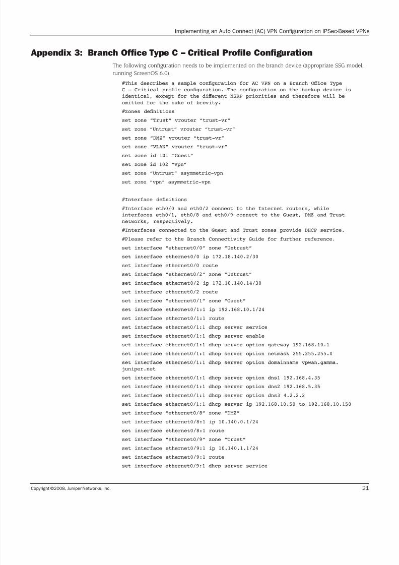
Appendix 3: Branch Office Type C – Critical Profile Configuration
The following configuration needs to be implemented on the branch device (appropriate SSG model,
running ScreenOS 6.0).
#This describes a sample conguration for AC VPN on a Branch Oice Type
C – Critical prole conguration. The conguration on the backup device is
identical, except for the dierent NSRP priorities and therefore will be
omitted for the sake of brevity.
#Zones denitions
set zone “Trust” vrouter “trust-vr”
set zone “Untrust” vrouter “trust-vr”
set zone “DMZ” vrouter “trust-vr”
set zone “VLAN” vrouter “trust-vr”
set zone id 101 “Guest”
set zone id 102 “vpn”
set zone “Untrust” asymmetric-vpn
set zone “vpn” asymmetric-vpn
#Interface denitions
#Interface eth0/0 and eth0/2 connect to the Internet routers, while
interfaces eth0/1, eth0/8 and eth0/9 connect to the Guest, DMZ and Trust
networks, respectively.
#Interfaces connected to the Guest and Trust zones provide DHCP service.
#Please refer to the Branch Connectivity Guide for further reference.
set interface “ethernet0/0” zone “Untrust”
set interface ethernet0/0 ip 172.18.140.2/30
set interface ethernet0/0 route
set interface “ethernet0/2” zone “Untrust”
set interface ethernet0/2 ip 172.18.140.14/30
set interface ethernet0/2 route
set interface “ethernet0/1” zone “Guest”
set interface ethernet0/1:1 ip 192.168.10.1/24
set interface ethernet0/1:1 route
set interface ethernet0/1:1 dhcp server service
set interface ethernet0/1:1 dhcp server enable
set interface ethernet0/1:1 dhcp server option gateway 192.168.10.1
set interface ethernet0/1:1 dhcp server option netmask 255.255.255.0
set interface ethernet0/1:1 dhcp server option domainname vpwan.gamma.
juniper.net
set interface ethernet0/1:1 dhcp server option dns1 192.168.4.35
set interface ethernet0/1:1 dhcp server option dns2 192.168.5.35
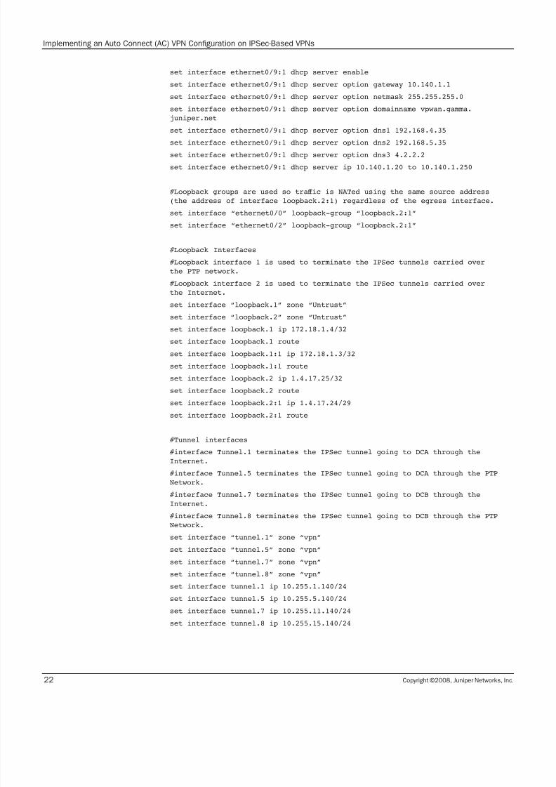
set interface ethernet0/1:1 dhcp server option dns3 4.2.2.2set interface ethernet0/1:1 dhcp server ip 192.168.10.50 to 192.168.10.150
set interface “ethernet0/8” zone “DMZ”
set interface ethernet0/8:1 ip 10.140.0.1/24
set interface ethernet0/8:1 route
set interface “ethernet0/9” zone “Trust”
set interface ethernet0/9:1 ip 10.140.1.1/24
set interface ethernet0/9:1 route
set interface ethernet0/9:1 dhcp server service
7/25/2019 Implementing an Auto Connect AC-VPN
http://slidepdf.com/reader/full/implementing-an-auto-connect-ac-vpn 22/28
Copyright ©2008, Juniper Networks, Inc.22
Implementing an Auto Connect (AC) VPN Configuration on IPSec-Based VPNs
set interface ethernet0/9:1 dhcp server enable
set interface ethernet0/9:1 dhcp server option gateway 10.140.1.1
set interface ethernet0/9:1 dhcp server option netmask 255.255.255.0
set interface ethernet0/9:1 dhcp server option domainname vpwan.gamma.
juniper.net
set interface ethernet0/9:1 dhcp server option dns1 192.168.4.35
set interface ethernet0/9:1 dhcp server option dns2 192.168.5.35
set interface ethernet0/9:1 dhcp server option dns3 4.2.2.2
set interface ethernet0/9:1 dhcp server ip 10.140.1.20 to 10.140.1.250
#Loopback groups are used so traic is NATed using the same source address
(the address of interface loopback.2:1) regardless of the egress interface.
set interface “ethernet0/0” loopback-group “loopback.2:1”
set interface “ethernet0/2” loopback-group “loopback.2:1”
#Loopback Interfaces
#Loopback interface 1 is used to terminate the IPSec tunnels carried over
the PTP network.
#Loopback interface 2 is used to terminate the IPSec tunnels carried over
the Internet.
set interface “loopback.1” zone “Untrust”
set interface “loopback.2” zone “Untrust”
set interface loopback.1 ip 172.18.1.4/32
set interface loopback.1 route
set interface loopback.1:1 ip 172.18.1.3/32
set interface loopback.1:1 route
set interface loopback.2 ip 1.4.17.25/32
set interface loopback.2 route
set interface loopback.2:1 ip 1.4.17.24/29
set interface loopback.2:1 route
#Tunnel interfaces
#interface Tunnel.1 terminates the IPSec tunnel going to DCA through the
Internet.
#interface Tunnel.5 terminates the IPSec tunnel going to DCA through the PTP
Network.
#interface Tunnel.7 terminates the IPSec tunnel going to DCB through the
Internet.
#interface Tunnel.8 terminates the IPSec tunnel going to DCB through the PTP
Network.
set interface “tunnel.1” zone “vpn”
set interface “tunnel.5” zone “vpn”set interface “tunnel.7” zone “vpn”
set interface “tunnel.8” zone “vpn”
set interface tunnel.1 ip 10.255.1.140/24
set interface tunnel.5 ip 10.255.5.140/24
set interface tunnel.7 ip 10.255.11.140/24
set interface tunnel.8 ip 10.255.15.140/24
7/25/2019 Implementing an Auto Connect AC-VPN
http://slidepdf.com/reader/full/implementing-an-auto-connect-ac-vpn 23/28
Copyright ©2008, Juniper Networks, Inc. 23
Implementing an Auto Connect (AC) VPN Configuration on IPSec-Based VPNs
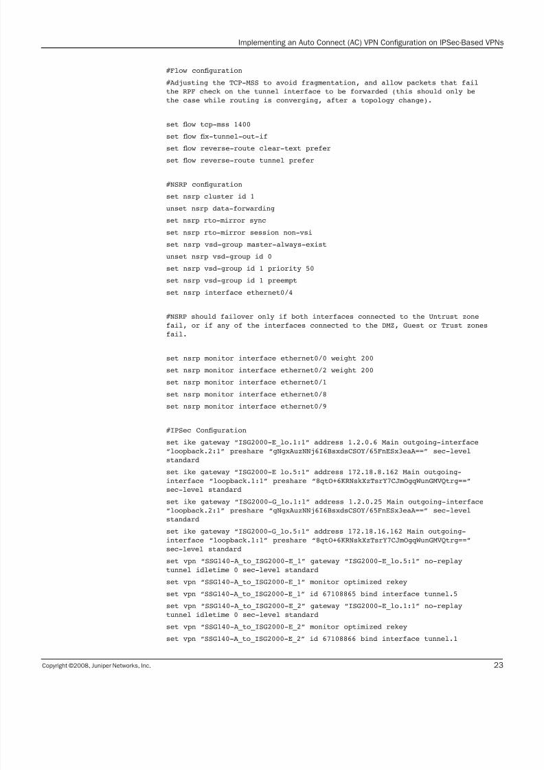
#Flow conguration
#Adjusting the TCP-MSS to avoid fragmentation, and allow packets that fail
the RPF check on the tunnel interface to be forwarded (this should only be
the case while routing is converging, after a topology change).
set ow tcp-mss 1400
set ow x-tunnel-out-if
set ow reverse-route clear-text prefer
set ow reverse-route tunnel prefer
#NSRP conguration
set nsrp cluster id 1
unset nsrp data-forwarding
set nsrp rto-mirror sync
set nsrp rto-mirror session non-vsi
set nsrp vsd-group master-always-exist
unset nsrp vsd-group id 0
set nsrp vsd-group id 1 priority 50set nsrp vsd-group id 1 preempt
set nsrp interface ethernet0/4
#NSRP should failover only if both interfaces connected to the Untrust zone
fail, or if any of the interfaces connected to the DMZ, Guest or Trust zones
fail.
set nsrp monitor interface ethernet0/0 weight 200
set nsrp monitor interface ethernet0/2 weight 200
set nsrp monitor interface ethernet0/1
set nsrp monitor interface ethernet0/8
set nsrp monitor interface ethernet0/9
#IPSec Conguration
set ike gateway “ISG2000-E_lo.1:1” address 1.2.0.6 Main outgoing-interface
“loopback.2:1” preshare “gNgxAuzNNj6I6BsxdsCSOY/65FnESx3eaA==” sec-level
standard
set ike gateway “ISG2000-E_lo.5:1” address 172.18.8.162 Main outgoing-
interface “loopback.1:1” preshare “8qtO+6KRNskXzTsrY7CJmOgqWunGMVQtrg==”
sec-level standard
set ike gateway “ISG2000-G_lo.1:1” address 1.2.0.25 Main outgoing-interface
“loopback.2:1” preshare “gNgxAuzNNj6I6BsxdsCSOY/65FnESx3eaA==” sec-level
standard
set ike gateway “ISG2000-G_lo.5:1” address 172.18.16.162 Main outgoing-
interface “loopback.1:1” preshare “8qtO+6KRNskXzTsrY7CJmOgqWunGMVQtrg==”sec-level standard
set vpn “SSG140-A_to_ISG2000-E_1” gateway “ISG2000-E_lo.5:1” no-replay
tunnel idletime 0 sec-level standard
set vpn “SSG140-A_to_ISG2000-E_1” monitor optimized rekey
set vpn “SSG140-A_to_ISG2000-E_1” id 67108865 bind interface tunnel.5
set vpn “SSG140-A_to_ISG2000-E_2” gateway “ISG2000-E_lo.1:1” no-replay
tunnel idletime 0 sec-level standard
set vpn “SSG140-A_to_ISG2000-E_2” monitor optimized rekey
set vpn “SSG140-A_to_ISG2000-E_2” id 67108866 bind interface tunnel.1
7/25/2019 Implementing an Auto Connect AC-VPN
http://slidepdf.com/reader/full/implementing-an-auto-connect-ac-vpn 24/28
Copyright ©2008, Juniper Networks, Inc.24
Implementing an Auto Connect (AC) VPN Configuration on IPSec-Based VPNs
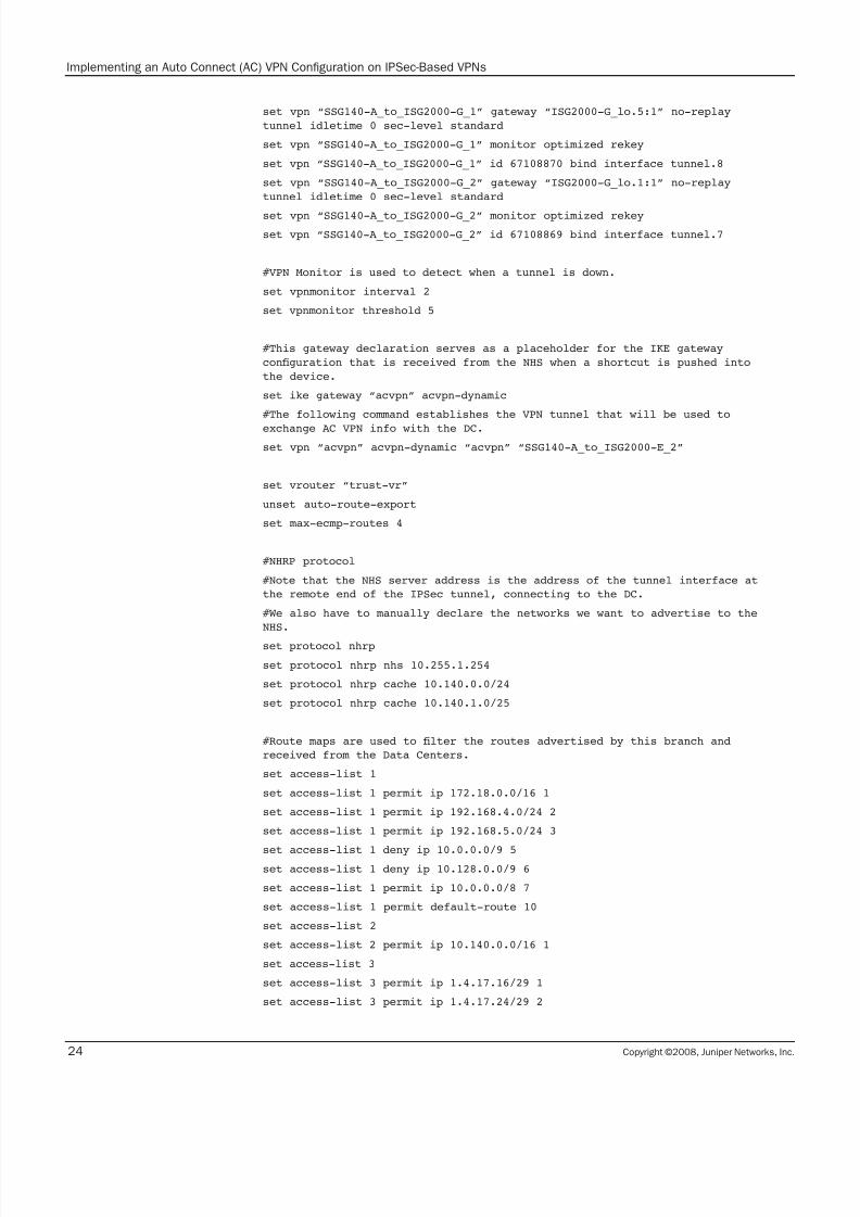
set vpn “SSG140-A_to_ISG2000-G_1” gateway “ISG2000-G_lo.5:1” no-replay
tunnel idletime 0 sec-level standard
set vpn “SSG140-A_to_ISG2000-G_1” monitor optimized rekey
set vpn “SSG140-A_to_ISG2000-G_1” id 67108870 bind interface tunnel.8
set vpn “SSG140-A_to_ISG2000-G_2” gateway “ISG2000-G_lo.1:1” no-replay
tunnel idletime 0 sec-level standard
set vpn “SSG140-A_to_ISG2000-G_2” monitor optimized rekey
set vpn “SSG140-A_to_ISG2000-G_2” id 67108869 bind interface tunnel.7
#VPN Monitor is used to detect when a tunnel is down.
set vpnmonitor interval 2
set vpnmonitor threshold 5
#This gateway declaration serves as a placeholder for the IKE gateway
conguration that is received from the NHS when a shortcut is pushed into
the device.
set ike gateway “acvpn” acvpn-dynamic
#The following command establishes the VPN tunnel that will be used to
exchange AC VPN info with the DC.
set vpn “acvpn” acvpn-dynamic “acvpn” “SSG140-A_to_ISG2000-E_2”
set vrouter “trust-vr”
unset auto-route-export
set max-ecmp-routes 4
#NHRP protocol
#Note that the NHS server address is the address of the tunnel interface at
the remote end of the IPSec tunnel, connecting to the DC.
#We also have to manually declare the networks we want to advertise to the
NHS.
set protocol nhrp
set protocol nhrp nhs 10.255.1.254
set protocol nhrp cache 10.140.0.0/24
set protocol nhrp cache 10.140.1.0/25
#Route maps are used to lter the routes advertised by this branch and
received from the Data Centers.
set access-list 1
set access-list 1 permit ip 172.18.0.0/16 1
set access-list 1 permit ip 192.168.4.0/24 2
set access-list 1 permit ip 192.168.5.0/24 3
set access-list 1 deny ip 10.0.0.0/9 5set access-list 1 deny ip 10.128.0.0/9 6
set access-list 1 permit ip 10.0.0.0/8 7
set access-list 1 permit default-route 10
set access-list 2
set access-list 2 permit ip 10.140.0.0/16 1
set access-list 3
set access-list 3 permit ip 1.4.17.16/29 1
set access-list 3 permit ip 1.4.17.24/29 2
7/25/2019 Implementing an Auto Connect AC-VPN
http://slidepdf.com/reader/full/implementing-an-auto-connect-ac-vpn 25/28
Copyright ©2008, Juniper Networks, Inc. 25
Implementing an Auto Connect (AC) VPN Configuration on IPSec-Based VPNs
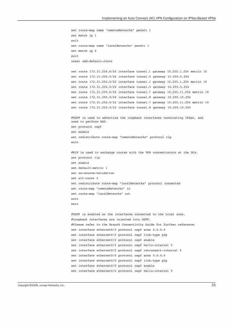
set route-map name “remoteNetworks” permit 1
set match ip 1
exit
set route-map name “localNetworks” permit 1
set match ip 2
exit
unset add-default-route
set route 172.31.254.0/24 interface tunnel.1 gateway 10.255.1.254 metric 10
set route 172.31.254.0/24 interface tunnel.5 gateway 10.255.5.254
set route 172.31.252.0/22 interface tunnel.1 gateway 10.255.1.254 metric 10
set route 172.31.252.0/22 interface tunnel.5 gateway 10.255.5.254
set route 172.31.255.0/24 interface tunnel.7 gateway 10.255.11.254 metric 10
set route 172.31.255.0/24 interface tunnel.8 gateway 10.255.15.254
set route 172.31.252.0/22 interface tunnel.7 gateway 10.255.11.254 metric 10
set route 172.31.252.0/22 interface tunnel.8 gateway 10.255.15.254
#OSPF is used to advertise the loopback interfaces terminating IPSec, and
used to perform NAT.
set protocol ospf
set enable
set redistribute route-map “remoteNetworks” protocol rip
exit
#RIP is used to exchange routes with the VPN concentrators at the DCs.
set protocol rip
set enable
set default-metric 1
set no-source-validation
set alt-route 3
set redistribute route-map “localNetworks” protocol connected
set route-map “remoteNetworks” in
set route-map “localNetworks” out
exit
exit
#OSPF is enabled on the interfaces connected to the trust zone.
#Loopback interfaces are injected into OSPF.
#Please refer to the Branch Connectivity Guide for further reference.
set interface ethernet0/2 protocol ospf area 0.0.0.0set interface ethernet0/2 protocol ospf link-type p2p
set interface ethernet0/2 protocol ospf enable
set interface ethernet0/2 protocol ospf hello-interval 5
set interface ethernet0/2 protocol ospf retransmit-interval 4
set interface ethernet0/0 protocol ospf area 0.0.0.0
set interface ethernet0/0 protocol ospf link-type p2p
set interface ethernet0/0 protocol ospf enable
set interface ethernet0/0 protocol ospf hello-interval 5

7/25/2019 Implementing an Auto Connect AC-VPN
http://slidepdf.com/reader/full/implementing-an-auto-connect-ac-vpn 26/28
Copyright ©2008, Juniper Networks, Inc.26
Implementing an Auto Connect (AC) VPN Configuration on IPSec-Based VPNs
set interface ethernet0/0 protocol ospf retransmit-interval 4
set interface loopback.1 protocol ospf area 0.0.0.0
set interface loopback.1 protocol ospf passive
set interface loopback.1 protocol ospf enable
set interface loopback.2 protocol ospf area 0.0.0.0
set interface loopback.2 protocol ospf passive
set interface loopback.2 protocol ospf enable
set interface loopback.1:1 protocol ospf area 0.0.0.0
set interface loopback.1:1 protocol ospf passive
set interface loopback.1:1 protocol ospf enable
set interface loopback.2:1 protocol ospf area 0.0.0.0
set interface loopback.2:1 protocol ospf passive
set interface loopback.2:1 protocol ospf enable
#RIP using on-demand circuit extensions has to be enabled on the tunnel
interfaces for the RIP exchange to take place.
set interface tunnel.1 protocol rip
set interface tunnel.1 protocol rip enable
set interface tunnel.1 protocol rip metric 2
set interface tunnel.1 protocol rip demand-circuit
set interface tunnel.5 protocol rip
set interface tunnel.5 protocol rip enable
set interface tunnel.5 protocol rip demand-circuit
set interface tunnel.7 protocol rip
set interface tunnel.7 protocol rip enable
set interface tunnel.7 protocol rip metric 2
set interface tunnel.7 protocol rip demand-circuit
set interface tunnel.8 protocol rip
set interface tunnel.8 protocol rip enableset interface tunnel.8 protocol rip metric 2
set interface tunnel.8 protocol rip demand-circuit
#NHRP has to be enabled on the tunnel interface connecting to the DC. This
MUST be a numbered interface.
set interface tunnel.1 protocol nhrp enable

7/25/2019 Implementing an Auto Connect AC-VPN
http://slidepdf.com/reader/full/implementing-an-auto-connect-ac-vpn 27/28
Copyright ©2008, Juniper Networks, Inc. 27
Implementing an Auto Connect (AC) VPN Configuration on IPSec-Based VPNs
About Juniper Networks
Juniper Networks, Inc. is the leader in high-performance networking. Juniper offers a
high-performance network infrastructure that creates a responsive and trusted environment
for accelerating the deployment of services and applications over a single network. This fuels
high-performance businesses. Additional information can be found at www.juniper.net.

7/25/2019 Implementing an Auto Connect AC-VPN
http://slidepdf.com/reader/full/implementing-an-auto-connect-ac-vpn 28/28
Copyright 2008 Juniper Networks, Inc. All rights reserved. Juniper Networks,
the Juniper Networks logo, NetScreen, and ScreenOS are registered trademarks
of Juniper Networks, Inc. in the United States and other countries. JUNOS and
JUNOSe are trademarks of Juniper Networks, Inc. All other trademarks, service
marks, registered trademarks, or registered service marks are the property of
their respective owners. Juniper Networks assumes no responsibility for any
inaccuracies in this document. Juniper Networks reserves the right to change,
modify, transfer, or otherwise revise this publication without notice.
CORPORATE HEADQUARTERS
AND SALES HEADQUARTERS FOR
NORTH AND SOUTH AMERICA
Juniper Networks, Inc.
1194 North Mathilda Avenue
Sunnyvale, CA 94089 USA
Phone: 888.JUNIPER (888.586.4737)
or 408.745.2000
Fax: 408.745.2100
www.juniper.net
EAST COAST OFFICE
Juniper Networks, Inc.
10 Technology Park Drive
Westford, MA 01886-3146 USA
Phone: 978.589.5800
Fax: 978.589.0800
ASIA PACIFIC REGIONAL SALES HEADQUARTERS
Juniper Networks (Hong Kong) Ltd.
26/F, Cityplaza One
1111 King’s Road
Taikoo Shing, Hong Kong
Phone: 852.2332.3636Fax: 852.2574.7803
EUROPE, MIDDLE EAST, AFRICA
REGIONAL SALES HEADQUARTERS
Juniper Networks (UK) Limited
Building 1
Aviator Park
Station Road
Addlestone
Surrey, KT15 2PG, U.K.
Phone: 44.(0).1372.385500
Fax: 44.(0).1372.385501
To purchase Juniper Networks solutions, please
contact your Juniper Networks sales representative
at 1-866-298-6428 or authorized reseller.
Implementing an Auto Connect (AC) VPN Configuration on IPSec-Based VPNs
Related Documents