Implementing a TCP Hole Punching NAT Traversal Solution for P2P Applications Using Netty Zeyad Tareq Mikhael Haddad September 2010 Dissertation submitted in partial fulfilment for the degree of Master of Science in Advanced Computing Department of Computing Science and Mathematics University of Stirling

Implementing a TCP Hole Punching NAT Traversal Solution for P2P Applications Using Netty
Nov 29, 2015
The goal of this project is to design and implement a NAT traversal solution using netty framework.
Welcome message from author
This document is posted to help you gain knowledge. Please leave a comment to let me know what you think about it! Share it to your friends and learn new things together.
Transcript

Implementing a TCP Hole Punching NAT Traversal
Solution for P2P Applications Using Netty
Zeyad Tareq Mikhael Haddad
September 2010
Dissertation submitted in partial fulfilment for the degree of
Master of Science in Advanced Computing
Department of Computing Science and Mathematics
University of Stirling
- i -
Abstract
Peer To Peer architectures, abbreviated (P2P), are very successful networking
architectures, and they are continuously developed and increasingly used, for the fact
that they support efficient distribution of resources and are stable against disturbances
such as bottlenecks, local network failures or denial of service attacks. Network Address
Translator, abbreviated (NAT), introduced to overcome the lack of IPv4 addresses; it
acts like an interface between the Internet and the LAN. The advantages for using NATs
are private IP addresses reusability, and additional security because of the NATs firewall
like behaviour. The disadvantage for using NATs is the NAT Traversal problem in P2P
applications. Running a service behind a NAT arise the NAT traversal problem, because
NAT boxes don't have an automatic mechanism to direct the incoming packets to the
right internal host. Port forwarding, relays and Hole Punching are popular methods to
solve the NAT traversal problem.
The goal of this project is to design and implement a NAT traversal solution
which will decrease the load on the server by decreasing the number of relayed
connections, but has a reasonable scalability, a Java based solution because OneDrum
uses JXTA framework to develop P2P applications, and also java uses a safe
environment and allows a lot of powerful libraries like Netty which was used in the
implemented solution, a solution that uses a reliable transport layer protocol TCP in all
communications; the data transfer, information message exchange and the Hole
Punching algorithm, a solution that is simple to understand by other developers, simple
to be integrated into other applications, also a tested solution and proved to be working.
However, using TCP in performing Hole Punching mechanism, adds extra complexity
to the Hole Punching mechanism, but on the other hand, reliable sessions will be
formed and that is easy to manage and eliminate the complexity that has to be added to
the unreliable UDP connections in order to transfer reliable data over UDP.
Researches on different Hole Punching approaches were undergone; these
approaches have some points of strength as well as weaknesses, these points of strength
and weaknesses were described in this dissertation. According to OneDrum company
requirements, the NAT traversal solution proposed by this dissertation for Cone based
NATs was successfully implemented using java, with the aid of Netty library and the
TCP Hole Punching was performed, tested and proved to be working.

- ii -
Attestation
I understand the nature of plagiarism, and I am aware of the University's policy on this
I certify that this dissertation reports original work by me during my University project.
Signature Date

- iii -
Acknowledgements
First of all, I would like to acknowledge my supervisor Dr. Mario Kolberg for his
unlimited support, guidance and valuable suggestions during the period of accomplishing
this dissertation.
Also, I would like to thank my family for their endless support and love during all the
years of carrying out my studies, especially during the last three months while I was
writing this dissertation, and for the encouragement they give me whenever I face an
obstacle.
Also, I would like to thank my teachers, friends, classmates and all who supported me
during the past academic year.

- iv -
Table of Contents
Abstract ............................................................................................................... i
Attestation .......................................................................................................... ii
Acknowledgements ........................................................................................... iii
Table of Contents .............................................................................................. iv
List of Figures .................................................................................................. vii
1 Introduction ................................................................................................. 1
1.1 Dissertation Background ...................................................................... 1
1.2 Dissertation Objectives......................................................................... 1
1.3 Achievements ....................................................................................... 2
1.4 Dissertation Overview .......................................................................... 2
2 State of The Art ............................................................................................ 3
2.1 Client Server Architecture .................................................................... 3
2.1.1 Advantages and Disadvantages of Client Server Architecture ....... 3
2.2 Peer To Peer Architecture .................................................................... 4
2.2.1 Structured Peer To Peer networks .................................................. 5
2.2.2 Distributed Hash Tables .................................................................. 5
2.2.2.1 Chord ........................................................................................ 6
2.2.2.2 CAN ......................................................................................... 6
2.2.3 P2P Topologies ............................................................................... 7
2.2.3.1 Ring Topology ......................................................................... 7
2.2.3.2 Hierarchical Topology ............................................................. 7
2.2.4 Unstructured Peer To Peer networks .............................................. 8
2.2.4.1 Query Flooding ........................................................................ 9
2.2.4.2 Random walk ........................................................................... 9
- v -
2.2.4.3 Pure Peer To Peer Networks .................................................. 10
2.2.5 Hybrid Peer To Peer Networks ..................................................... 10
2.3 Advantages and Disadvantages of P2P Networks .............................. 12
2.4 Network Address Translation ............................................................. 13
2.4.1 Full Cone NAT ............................................................................. 13
2.4.2 Address Restricted Cone NAT ..................................................... 14
2.4.3 Port Restricted Cone NAT ............................................................ 14
2.4.4 Symmetric NAT ............................................................................ 15
2.4.5 NAT Summary .............................................................................. 15
2.5 NAT Traversal Techniques ................................................................ 16
2.5.1 Port Forwarding ............................................................................ 16
2.5.2 Upnp .............................................................................................. 16
2.5.3 Application Layer Gateways ........................................................ 17
2.5.4 STUN ............................................................................................ 17
2.5.5 TURN ............................................................................................ 18
2.5.6 Hole Punching ............................................................................... 18
2.6 Peer To Peer in NAT Environment .................................................... 19
2.7 NAT Traversal Related Work ............................................................ 19
2.7.1 NatTrav ......................................................................................... 20
2.7.2 Concurrent / Parallel Hole Punching ............................................ 21
2.7.3 STUNT .......................................................................................... 22
2.7.4 JXTA ............................................................................................. 22
2.7.5 Skype ............................................................................................ 23
2.8 Summary ............................................................................................ 23
3 NatTrav Library Testing ............................................................................ 25
3.1 NatTrav Testing Scenarios .................................................................. 25

- vi -
4 Design ........................................................................................................ 29
4.1 The Requirements .............................................................................. 29
4.2 The NAT Traversal Approach ............................................................. 30
4.2.1 The NAT Traversal Approach Messages....................................... 32
4.3 The Software Design .......................................................................... 33
5 Implementation .......................................................................................... 36
5.1 NettyNatTrav ...................................................................................... 36
5.1.1 Netty Library ................................................................................. 36
5.1.2 The Codec ..................................................................................... 38
5.1.3 The Library Structure .................................................................... 39
5.2 The Sample Application ..................................................................... 44
6 Testing ....................................................................................................... 46
6.1 Practical Experiment .......................................................................... 46
6.2 Software Testing ................................................................................. 47
6.2.1 Unit testing .................................................................................... 47
6.2.2 Integration Testing ........................................................................ 50
7 Conclusion ................................................................................................. 52
7.1 Summary ............................................................................................ 52
7.2 Evaluation ........................................................................................... 52
7.3 Future Work ........................................................................................ 54
References ........................................................................................................ 55
- vii -
List of Figures
Figure 1. Client Server Architecture ................................................................................... 3
Figure 2. Ring Topology. .................................................................................................... 7
Figure 3. Hierarchical Topology ......................................................................................... 8
Figure 4. Pure P2P Topology............................................................................................. 10
Figure 5. Super Node Hybrid P2P Topology..................................................................... 11
Figure 6. Full Cone NAT .................................................................................................. 13
Figure 7. Address Restricted Cone NAT ........................................................................... 14
Figure 8. Port Restricted Cone NAT ................................................................................. 15
Figure 9. Symmetric NAT ................................................................................................. 15
Figure 10. NatTrav Sequential Hole Punching protocol ................................................. 20
Figure 11. NatTrav Test Scenario 1 ................................................................................. 25
Figure 12. NatTrav Test Scenario 2 ................................................................................. 26
Figure 13. NatTrav Test Scenario 3 ................................................................................. 27
Figure 14. NatTrav Test Scenario 4 ................................................................................. 28
Figure 15. NAT traversal approach design and messages flow ....................................... 30
Figure 16. nettynattrav Package ...................................................................................... 34
Figure 17. The commandline Package ............................................................................ 34
Figure 18. The test Package ............................................................................................ 35
Figure 19. Netty Framework ........................................................................................... 37
Figure 20. Encoded ConnectMessage Frame .................................................................. 38
Figure 21. Encoded RemoteEdgePeerInfoMessage Frame ............................................. 38
Figure 22. Encoded ConnectionCompletedMessage Frame ........................................... 39
Figure 23. Encoded CloseConnectionWithMessage Frame ............................................ 39
Figure 24. Library Practical Test ..................................................................................... 46

- viii -
Figure 25. EncoderDecoderTest Screenshot ................................................................... 48
Figure 26. MapKeyTest Screenshot ................................................................................ 49
Figure 27. ConnectionRegistryTest Screenshot .............................................................. 50
Figure 28. IntegrationTest Screenshot ............................................................................. 51
Figure 29. WireShark Screenshot .................................................................................... 53
- 1 -
1 Introduction
Peer To Peer architectures, abbreviated (P2P), are very successful networking
architectures, and they are continuously developed and increasingly used, for the fact that
they support efficient distribution of resources and are stable against disturbances such as
bottlenecks, local network failures or denial of service attacks. Skype is one of the most
famous and a leading P2P application, especially in solving P2P connection problems like
running on peers from behind NAT devices which is known as the NAT traversal problem.
The subsequent sections will describe in details the dissertation context as well as the
dissertation objectives and the achievements done by this dissertation.
1.1 Dissertation Background
Network Address Translator, abbreviated (NAT), introduced to overcome the lack
of IPv4 addresses; it acts like an interface between the Internet and the LAN. The
advantages for using NATs are private IP addresses reusability, and additional security
because the NATs firewall like behaviour. The disadvantage for using NATs is the NAT
Traversal problem in P2P applications. Running a service behind a NAT arise the NAT
traversal problem, because NAT boxes don't have an automatic mechanism to direct the
incoming packets to the right internal host. Port forwarding, relays and Hole Punching are
popular methods to solve the NAT traversal problem.
1.2 Dissertation Objectives
The goal of this project is to design and implement a NAT traversal solution, which
will decrease the load on the server by decreasing the number of relayed connections, but
has a reasonable scalability, a Java based solution because OneDrum uses JXTA
framework to develop P2P applications, and also java uses a safe environment and allows a
lot of powerful libraries like Netty which was used in the implemented solution, a solution
that uses a reliable transport layer protocol TCP in all communications; the data transfer,
information message exchange and the Hole Punching mechanism, a solution that is simple
to understand by other developers, simple to be integrated into other applications, and also
a tested solution that has been proven to be working. However, using TCP in performing

- 2 -
Hole Punching mechanism, adds extra complexity to the Hole Punching mechanism for the
fact that TCP connection allows only binding to a specific port or sending data through that
specific port but not both, but on the other hand, reliable sessions will be formed and that is
easy to manage and eliminate the complexity that has to be added to the unreliable UDP
connections in order to transfer reliable data over UDP.
1.3 Achievements
Researches on different Hole Punching solutions were undergone; these solutions
have some points of strength as well as weaknesses. NatTrav library was tested thoroughly
as described in chapter 3. According to OneDrum company requirements, the NAT
traversal solution proposed by this dissertation for Cone based NATs as described in
chapter 4, was successfully implemented using java, with the aid of Netty library and the
TCP Hole Punching was performed as described in chapter 5, and tested as described in
chapter 6.
1.4 Dissertation Overview
The dissertation is structured as follows: chapter 2 will describe the client server
architecture and peer to peer architecture, the advantages and disadvantages of both
architectures, Network Address Translators, why they were created, what are NATs used
for, what are the general types of NAT, what are the advantages and disadvantages of
using NATs, and what are the solutions for the problems arisen by NATs. A conclusion
section based on a simple comparison between the reviewed solutions will give the reasons
behind implementing the Netty NatTrav from scratch, while chapter 3 will give in details
the testing results of four different testing scenarios, for one of the solutions reviewed
which is NatTrav library, followed by chapter 4 which give in details the design of the
implemented solution, and Chapter 5 will show in details the process of implementing the
implemented solution, a TCP Hole Punching solution which was created from scratch
using Netty library, while chapter 6 will give in details the testing process, and finally,
chapter 7 will give the conclusion based on the evaluation of the implemented solution,
and what can be added to the implemented solution as future work, that makes the solution
more complete and fulfill wider range of P2P applications developers' requirements.

- 3 -
2 State of The Art
This chapter will give a brief introduction to the project theoretical background.
The first part of this chapter will describe the client server architecture and peer to peer
architecture, the advantages and disadvantages of both architectures, while the second part
is concerned with Network Address Translation, why they were created, what are NATs
used for, what are the general types of NAT, what are the advantages and disadvantages of
using NATs, and what are the solutions for the problems arisen by NATs. A conclusion
section will give the reasons behind implementing the Netty NatTrav from scratch.
2.1 Client Server Architecture
The client server network is a network that consists of two types of hosts, the
providers of a resource or service, called servers, and service requesters, called clients.
Clients usually request services from remote hosts which are running as the servers, but
both client and server may reside in the same system. A server machine is a host that is
running one or more service programs known as the daemon, waiting and listening for the
clients' requests. A client does not share any of its resources therefore initiate
communication sessions with servers to request resources [12].
Figure 1. Client Server Architecture
2.1.1 Advantages and Disadvantages of Client Server Architecture
Since all the data stored on servers, so it is easy to control the data and maintain
security aspects like authentication and authorization to manage the data access and
changing of the data to be made by authorized clients.
Server
Client
Client

- 4 -
Since data storage is centralized, it is easy to the network administer to update the
data and therefore no data consistency problem.
As s disadvantage, the server can be a bottle neck if the clients' requests increase
drastically, and to solve this problem using multiple servers will introduce other
issues like data consistency and costs.
Since all the data stored in the server, if the server fails all the client will not be able
to get the data, so the server is a single point of failure.
2.2 Peer To Peer Architecture
A peer to peer architecture abbreviated as P2P is a network architecture composed
of hosts sharing resources, allowing other hosts to access these resources without the need
for central server for coordination because all peers are both suppliers and consumers of
resources. Peer to peer networks are typically formed by ad-hoc connection.
Highly distributed applications were used along time before peer to peer
applications were introduced in the late 1990s. USENET is an example, the software that
manages news group's message flow, was written in 1979 by Tom Truscott and Jim Ellis in
North Carolina for a small network of three machines. This early system was already able
to exchange news items among its members, independent of the place they were originally
injected. USENET kept a data set up to date, distributed over several machines. Many
years later, when the former networks created by DOD for military use, had become
available to the public known as the internet, the first modern peer to peer applications like
Napster became more and more popular in a very short time. Because they usually allowed
their users to break copyright laws by sharing music files, the peer to peer technology
became related to digital piracy and copyright violation.
While those first peer to peer file sharing applications had a single point of failure
which is the central coordination server, later ones became completely distributed and
therefore much harder to control by the authorities if they were used for illegal purposes,
but at the same time, the peer to peer technology has proven to be capable of doing much
more than copyright piracy, like distributed applications for storing data as in OceanStore
or looking up Voice over IP peers as used by Skype. Peer to peer applications abandon the
- 5 -
use of traditional client server architecture, instead of that, every host in peer to peer
networks can act at a given moment either as a server responding to other client(s), or as a
client requesting resources from other client, so the peers can be considered equal in peer
to peer networks. But since every peer can offer its services to the other peers in the
network, there must be a way to find the peers that hold the desired resource or service.
Peer to peer systems typically implement an application layer overlay network or a
virtual topology on top of the physical network topology. These overlays are used for
indexing and peer discovery and are exchanged directly over the network. The P2P overlay
network consists of all the participating peers as network nodes. P2P networks can be
classified as structured, unstructured or hybrid according to the way the nodes in the
overlay network are linked to each other. All peer to peer networks have one thing in
common; a connection between the peer requesting a service or a resource, and the peer
offering the service or the resource. The process of how those two peers find each other
can be implemented in different ways. General topologies and ways of indexing will be
explained in the following sections [13].
2.2.1 Structured Peer To Peer networks
The Structured peer to peer networks, has two types of connections in the overlay
flat or fixed. Distributed hash tables (DHT) typically used for indexing, such as in the
Chord systems. Structured P2P networks uses a routing techniques that routes a search to
some peer that has the desired file, even if the file is extremely rare. The common type of
structured P2P network is the distributed hash table, in which a fixed hash entry in the table
is used to assign each file to a particular peer [12].
2.2.2 Distributed Hash Tables
Distributed hash tables are a types of decentralized distributed systems which
provide a way to lookup service similar to a hash table which has a unique key for each
value stored in the table and both pairs are stored in the DHT, any node can get the value
associated with a given key. The mapping from keys to values is distributed among the
nodes; in a way that does not cause a lot of disruption if the table updated. This allows
DHTs to scale to extremely large numbers of nodes and to handle continual node arrivals,

- 6 -
departures, and failures. Notable distributed networks that use DHTs include BitTorrent's
distributed tracker, the Bitcoin monetary network, the Kad network, the Storm botnet,
YaCy, and the Coral Content Distribution Network.
In a DHT network, every node has a unique identifier and the efficiency of the
overlay network has a direct impact on the scalability of the system where each node
maintains a routing table containing pointers to a small number of other neighbor nodes, so
that the incoming queries are forwarded to the node that is closest to the look up key. DHT
systems vary in measuring the closeness of the requested node. The following sections
briefly describe the most important DHTs and their characteristics [12].
2.2.2.1 Chord
Chord is a simple and common approach used in P2P networks. In the Chord
overlay network every node is assigned to an m-bit index or identifier arranged counter
clockwise in a virtual circle, this identifier is the hash code of the node's IP address. Also
every keys is assigned to an m-bit identifier, this identifier is the hash code of a keyword,
such as a file name. Every node maintains information about its direct neighbors in the ring
i.e. its successor and predecessor.
If there are N nodes and K keys, then each node is responsible for roughly K / N
keys. Chord requires each node to keep a finger table containing up to m entries. The ith
entry of node n will contain the address of successor (n + 2i). Using this finger table, the
number of nodes that must be contacted to find a successor in an N-node network is
O(logN) which is a faster approach to find the required node than if each node only knows
its direct successor [11].
2.2.2.2 CAN
In contrast to the other described overlay networks, CAN uses a d dimensional
Cartesian coordinate space on a d torus. Each peer is responsible for one zone in this space
and peers are called neighbors, if they are responsible for adjacent zones to the local peer.
Resources are mapped deterministically to a point in this space and belong to the node
responsible for that area.

- 7 -
A CAN node maintains a routing table that holds the IP address and virtual
coordinate zone of each of its neighbors. A node routes a message towards a destination
point in the coordinate space. First, the node determines the closest neighboring zone to
the destination point, and then uses the routing table looks up that zone's node's IP address
[11].
2.2.3 P2P Topologies
All P2P architectures have one thing in common; the actual data transfer between
two peers is done directly through a connection between the peer offering the resource and
the peer requesting it. The process of how those two peers find each other can be
implemented in different ways or topologies, the following section will explain general
peer to peer networks topologies [12].
2.2.3.1 Ring Topology
Here the services of the central server in client server architecture; are distributed
over all peers, which are arranged in a ring. These nodes work together to improve load
balancing and availability. Scalability can be improved in Token Ring networks, one of the
disadvantages of this topology is the failure of one of the peers will disrupt the network.
Figure 2 shows the Ring Topology [12].
Figure 2. Ring Topology.
2.2.3.2 Hierarchical Topology
In the hierarchical topology, the services offered by the server or central node in the
client server architecture are distributed among a tree like topology, in a way that a root
node offers services to its children, and these children acts like root nodes offering services
Peer
Peer Peer
Peer
Peer Peer

- 8 -
to their children, and so on till the leaf nodes. Examples for such distributed systems are
the Domain Name Service (DNS), Certification Authorities (CAs) or the USENET. All of
them have in common that there are always levels of importance or referencing, and the
work is distributed over that hierarchy [12].Figure 3 shows the Hierarchical topology.
Figure 3. Hierarchical Topology
2.2.4 Unstructured Peer To Peer networks
In unstructured peer to peer networks, there is no way of organization or
optimization of network connections. When the overlay links are arbitrarily been
established, this will form an unstructured P2P network. Such networks can be easily
constructed as a new peer that wants to join the network can copy existing links of another
node and then form its own links over time. If a peer wants to find a desired piece of data
in the network in an unstructured P2P network, the query has to be flooded through the
network to find as many peers as possible that share that data.
The main disadvantage for this kind of networks is that not always the queries are
resolved. Popular contents are likely to be available at several peers, so that any peer
searching for it, will find the same data. But if a peer is looking for data that is rarely exists
in the network, and shared by a few number of peers, then it is unlikely that a successful
search will be performed. In unstructured P2P, there is no guarantee that flooding will find
a peer that has the desired data, for the fact there is no way of referencing a peer and the
content it manages. Flooding consumes bandwidth because of the high amount of signaling
traffic it generates in the network and therefore affect the search efficiency, that's why such
networks typically have very poor search efficiency. Many of the popular P2P networks
are unstructured [13].
Peer
Peer Peer
Peer
Peer Peer Peer Peer

- 9 -
2.2.4.1 Query Flooding
Query flooding is a method to search for a resource on a P2P network. It is simple
but scales very poorly and thus is rarely used. Early versions of the Gnutella protocol
operated by query flooding; newer versions use more efficient search algorithms. In query
flooding, if a node wants to find a resource on the network, which may be on a node it does
not know about, it simply broadcast its search query to its immediate neighbors. If the
neighbors do not have the resource, it then asks its neighbors to forward the query to their
neighbors in turn. This is repeated until the resource is found or all the nodes have been
contacted. Query flooding is simple to implement and is practical for small networks with
few requests, it contacts all reachable nodes in the network and so can precisely determine
whether a resource can be found in the network. Every request may cause all nodes to be
contacted. Each node might generate a small number of queries; but however each of these
queries; floods the network, thus generating more traffic added to the network, which may
exceed the actual peer to peer data transfer in extreme cases. The larger the network; the
more query flooding traffic generated per node, making limiting its scalability. In addition,
because any node can flood the network simply by issuing a request for a nonexistent
resource, it is possible to launch a denial of service attack on the network [11].
2.2.4.2 Random walk
A random walk is a method to search for a resource on a P2P network. It is a
complicated mathematical formula for calculating a path that consists of taking successive
random steps. The results of random walk analysis have been applied to computer science,
psychology, physics, ecology, economics and a number of other fields as a fundamental
model for random processes in time. For example, the path traced by a molecule as it
travels in a liquid or a gas, the search path of a foraging animal, the price of a fluctuating
stock and the financial status of a gambler can all be modelled as random walks. The term
random walk was first introduced by Karl Pearson in 1905. There are different types of
random walks, often, random walks are assumed to be Markov chains or Markov
processes. According to [12], they have identified two cases where the use of random
walks for searching achieves better results than flooding, the first case is when the overlay
topology is clustered, and the second case is when a client re-issues the same query while
its horizon does not change much. Specific cases or limits of random walks include the
- 10 -
drunkard's walk and Lévy flight. Random walks are related to the diffusion models and are
a fundamental topic in discussions of Markov processes [12].
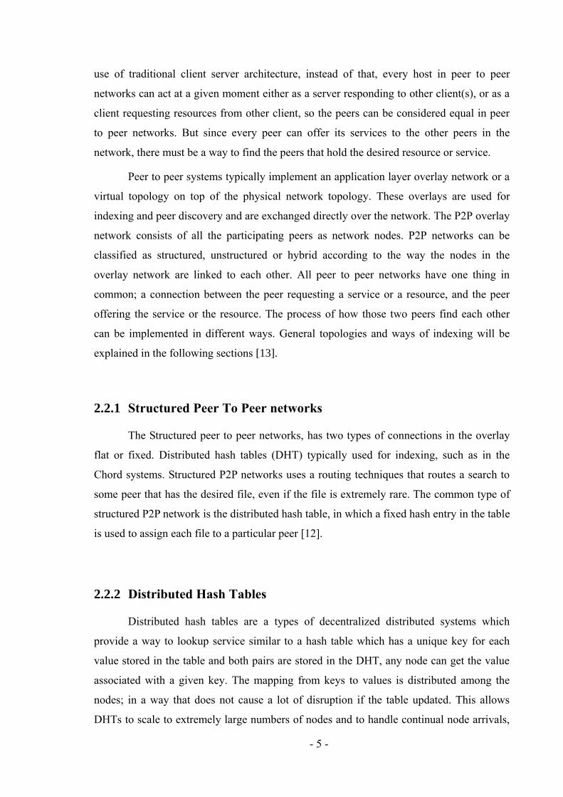
2.2.4.3 Pure Peer To Peer Networks
A pure P2P network does not consist of clients or servers but only equal
peer nodes that simultaneously function as both "clients" and "servers" to the other nodes
on the network. In pure peer to peer systems there is only one routing layer, as there are no
preferred nodes with any special infrastructure function. In pure P2P networks, there is no
central server managing the network, neither is there a central router. Some examples of
pure P2P networks designed for file sharing are old version of Gnutella and Freenet. Figure
4 shows the pure P2P topology [12].
Figure 4. Pure P2P Topology.
2.2.5 Hybrid Peer To Peer Networks
Hybrid peer to peer networks are mixtures of centralized client server like
topologies, and decentralized pure peer to peer topologies. They were introduced to try to
overcome the drawbacks of the basic topologies, and only bring their advantages together
in a hybrid form. Another type of hybrid P2P networks is networks using central server.
These networks are in general called centralized networks because they depend on their
central server. An example for such a network is the eDonkey network (eD2k), where a
central server is used for indexing and bootstrapping the entire system. All peers in this
topology have to register to the central server and stay connected for the whole time the
Peer Peer Peer
Peer
Peer
Peer
Peer
Peer
Peer

- 11 -
application is running. Search queries from the peers are directed towards the central server
which searches its internal database for matches. If this search succeeds, the querying peer
gets a result list with the peers offering the desired resource. To access this resource, a
direct connection between the two peers is established. This direct connection between the
peers distinguishes the centralized peer to peer topology from the client/server architecture,
since no actual resources are stored on the central peer. The drawback in this architecture is
that the central server can be a single point of failure. In case of central node failure, the
whole system fails. In case of heavy load on the central server, this bottleneck limits the
efficiency of the whole network. Napster is an example for applications that used
centralized topology. Another type of hybrid networks is the super node; which is instead
of having a centralized server, some of normal nodes get promoted to become local leaders
for other nodes, sometimes they are called group leader nodes, super nodes or ultra nodes.
The important fact about them is that they locally behave like central servers for a group of
other nodes. But among the group of super nodes every one of them is equal. What makes
a normal node a super node depends on the function of the application. Sometimes it is
enough for a normal peer to become a super peer, if it has enough bandwidth to share, in
other applications also the availability over time, or its reach ability in the network matters.
The super node keeps a list of peers attached to it and exchanges maintenance messages
with its neighbor super nodes.
Figure 5. Super Node Hybrid P2P Topology.
R
eply
Q
uer
y
Super
node
Peer
Peer
Peer
R
eply
Q
uer
y
Super
node
Peer
Peer
Super
node
Super
node
Peer
Peer
Peer
Peer
Peer Peer
Peer
R
eply
R
eply
Q
uer
y
Q
uer
y

- 12 -
Since super nodes only have to keep track of a relatively small group of attached peers, the
bottleneck is reduced, and the failure tolerance is increased. Examples for this hybrid
topology are Kazaa and its successor Skype. Figure 5 shows super node hybrid peer to peer
topology [12].
2.3 Advantages and Disadvantages of P2P Networks
In P2P networks, clients provide resources, which may include bandwidth, storage
space, and computing power. As nodes join the network, the request messages to the
system increases but the total capacity and resources of the system also increases. In
contrast, in typical client server architecture, only servers share their resources, while
clients only request resources from the server not from other clients. In this case, the more
clients join the system, the more resources are consumed to serve each client.
The distributed nature of P2P networks also increases activeness and efficiency by
enabling peers to find the data without relying on a centralized index server, eliminating
the single point of failure in the system. As with most network systems, unauthenticated,
unsigned, and unsecure codes may allow remote access to files on a victim's computer or
even compromise the entire network. The FastTrack network for example, faced these
kinds of attacks when anti P2P companies managed to introduce faked downloadable files,
which were unusable or contains malicious code.
P2P networks nowadays have increased their file verification mechanisms, security
and accessibility. Modern hashing, chunk verification, different encryption methods, login
accounts and firewalls are good examples for these aspects, which in turn, made most
networks capable of resisting almost any type of attack, even when major parts of the
respective network have been replaced by faked or nonfunctional hosts. Internet service
providers; usually reduce or limit the data transfer rate for P2P file sharing traffic due to
the high bandwidth usage. Compared to Web browsing, email or many other uses of the
internet, where data is only transferred in short intervals and relative small quantities, P2P
file sharing often consists of relatively heavy bandwidth usage due to ongoing file
transfers. P2P caching can be considered as a solution to the bandwidth problem, where an
ISP stores in the cache the most accessed files by the P2P clients in order to save access to
the Internet [13].

- 13 -
2.4 Network Address Translation
In the days of Napster, most internet users at home were connected to the World
Wide Web using dial up links where the users had to pay for the time they stayed
connected, and they did not remain online 24 hours a day. When broadband was introduced
in technologies such as ADSL and internet over TV cable, most internet service providers
changed their business by charging the clients monthly flat rates to access the internet,
sometimes with a limited amount of monthly transferred data, thus it was obvious that the
available IP address pool would run out shortly. This problem led to the invention of a
technique called network address translation, often abbreviated as NAT, as described in
1994. In these first publications about NAT, the authors already stated that it was only
meant to be a short term solution against IP address shortage, and would introduce several
new problems to networking, one of these problems as discovered later is the NAT
traversal problem, which was accidently found to be an advantage to the NAT because it
makes the NAT acts like a firewall to improve the clients security. NAT was easy to
implement for network routers; and soon most manufacturers offered devices using it.
Because RFC1631 was more like a description than a standard, it was implemented in
many different ways; and today's NAT devices have a large variety of behavior, which is
difficult to predict for unknown NAT model and manufacturer. In general, NAT behavior
can be classified into four types [12].
2.4.1 Full Cone NAT
In a full cone NAT, all requests from the same internal IP address and port number
(internal socket) are mapped to the same external IP address and port number (external
socket)
Figure 6. Full Cone NAT

- 14 -
External hosts can send packets to the internal host via its external socket without
any preceding connection attempts from behind the NAT device or any other restrictions.
Figure 6 shows the full cone NAT behavior [12].
2.4.2 Address Restricted Cone NAT
As with the Full Cone NAT, in address restricted cone NAT internal socket is
mapped to an external socket. The difference is unsolicited packets from outside will be
blocked and will not be forwarded into the LAN. This behavior creates additional security,
but it also makes it harder to establish peer to peer connections. An external host can only
send packets to the host behind the NAT only if the internal host has initially sent packets
to it. Figure 7 shows the Address Restricted Cone NAT behavior, where an internal host
Client sends a request to an external host Server1, thus only packets can be sent to Client
via the external socket from Server1, because Server1 IP address was used in an outgoing
connection from Client, Server1 can use any port number when sending packets to Client,
packets from Server2 will be blocked because Client did not contact Server2 previously
[12].
Figure 7. Address Restricted Cone NAT
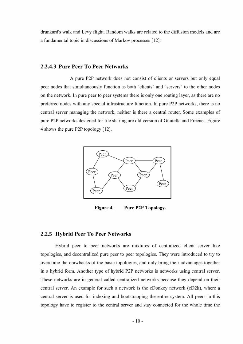
2.4.3 Port Restricted Cone NAT
In a Port Restricted Cone NAT, the constraints are even tighter than Address
Restricted Cone NAT. Here not only the IP address is checked for responses from the
external host, but also their port number. Figure 8 shows the Port Restricted Cone NAT.
Therefore, an application is allowed to send packets from the external host to the internal
host via the external socket using a specific source port, but can't use a different source
port, even if it is from the same machine [12].
- 15 -
Figure 8. Port Restricted Cone NAT
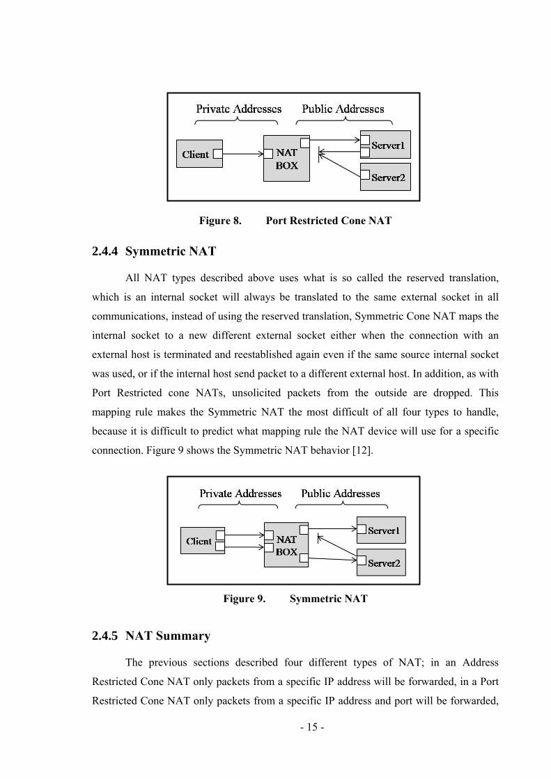
2.4.4 Symmetric NAT
All NAT types described above uses what is so called the reserved translation,
which is an internal socket will always be translated to the same external socket in all
communications, instead of using the reserved translation, Symmetric Cone NAT maps the
internal socket to a new different external socket either when the connection with an
external host is terminated and reestablished again even if the same source internal socket
was used, or if the internal host send packet to a different external host. In addition, as with
Port Restricted cone NATs, unsolicited packets from the outside are dropped. This
mapping rule makes the Symmetric NAT the most difficult of all four types to handle,
because it is difficult to predict what mapping rule the NAT device will use for a specific
connection. Figure 9 shows the Symmetric NAT behavior [12].
Figure 9. Symmetric NAT
2.4.5 NAT Summary
The previous sections described four different types of NAT; in an Address
Restricted Cone NAT only packets from a specific IP address will be forwarded, in a Port
Restricted Cone NAT only packets from a specific IP address and port will be forwarded,

- 16 -
and finally in a Symmetric NAT, no reserved translation is used, so a new translation for
every outgoing connection [12].
2.5 NAT Traversal Techniques
The presence of NAT devices can pose a problem if a certain host behind a NAT
device has to be reachable from within the public network. If a peer behind a NAT device
should be contacted from the outside, perhaps because it is providing services or in this
case a P2P instance on the public side is trying to contact another instance behind a NAT,
the NAT device will not find the necessary information in its translation table, and
therefore cannot tell to which internal host the data packages must be sent. There are
several techniques to solve this problem; the next section will explain those techniques
aside with their respective pros and cons [12].
2.5.1 Port Forwarding
Port Forwarding can be found within most NAT devices, because it is a straight
forward solution to make a given service inside a local network available to the outside.
However, the user must configure the NAT box via its configuration interface, which is
usually either over telnet or using a web interface, specifying the range of public ports to
be forwarded to a client within the local network. In order for the port forwarding to work,
two conditions must be satisfied first the internal host must have a fixed IP address, and
second, only one host behind a NAT box can offer its service at the same time to the public
on a given port. The second condition highly limits peer to peer applications, because they
often have an application specific port range. In other words, if port forwarding was
configured for one host in the local network, it would no longer be possible to enable a
second host for the same P2P application. Having a large company or university network,
using port forwarding will limit the participating of many users in P2P, which is an
advantageous side effect, from the network administrator perspective [12].
2.5.2 Upnp
UPnP is an abbreviation to Universal Plug and Play, which is a set of networking
protocols that permits networked devices, such as personal computers, printers, Internet

- 17 -
gateways, Wi-Fi access points, mobile device, to discover each other's presence on the
network and establish a connection between them. The UPnP was introduced by the
Universal Plug and Play Forum which is a Forum consists of over eight hundred vendors
involved in consumer electronics and network computing, to create a simple and robust
way to connect stand alone devices made by different vendors.
The concept of UPnP is an extension to plug and play technology used to
automatically connect devices directly to a computer. UPnP uses Simple Service Discovery
Protocol SSDP to discover the network to find the nearest control point and also broadcast
the presence of a control point. But the UPnP usually is disabled by default, for a good
reason. In 2001, the eEye company published a press release about three highly dangerous
security vulnerabilities existing in all versions of Windows. For instance, a machine
running Windows XP accessible from the internet could be easily attacked using a buffer
overflow, if the UPnP service on that machine was enabled and the machine was directly
exposed to the public internet [8].
2.5.3 Application Layer Gateways
Application Layer Gateways (ALGs) are application specific devices used as
gateways for nodes behind a NAT box to translate the address if it is not in the header of a
data packet because NAT only inspects and translates IP address information when it is in
the header of a data packet and if these addresses are in the payload, the NAT devices do
not detect it and cannot translate it to the appropriate correct address. ALG can be installed
either on the same node where the NAT resides or on different nodes along the
communication path. However, ALGs are application specific using them in wide range is
not applicable. Furthermore, ALGs task becomes more difficult if the payload is encrypted,
in this case ALGs will not be able to translate an internal address to an external one
because it cannot read the message [12].
2.5.4 STUN
The STUN protocol (Simple Traversal of User Datagram Protocol through Network
Address Translator) is a relatively simple mechanism that allows applications to discover
- 18 -
NATs and firewalls which are installed between them and the public internet. STUN also
allows two applications, both behind a NAT device, establishing a direct UDP connection
between them. STUN is often used in Voice over IP (VoIP) telephony together with the
Session Initiation Protocol (SIP) to allow the telephony applications behind a NAT device
to be reachable from the public internet [3].
2.5.5 TURN
TURN is an abbreviation for Traversal Using Relay NAT; it is a protocol that
enables clients resides behind a NAT box, to receive incoming data over TCP or UDP.
TURN usually used as plan B or the fallback strategy for STUN, if a specific NAT device
refuses to work as demanded by STUN, in this case TURN will relay all the traffic. If a
client wants to be available for other clients, it registers with a TURN server the server
then forwards all incoming data addressed to the client from a third host over the already
existing connection between the client and the TURN server. Because with TURN all
traffic between two peers has to be relayed by the TURN server, it can only be used as a
last resort, because the server must be available 24/7, with high bandwidth which leads to
more costs as the network scales up [4].
2.5.6 Hole Punching
Hole Punching is the term used to represent a mechanism to trick a NAT device by
taking advantage of properties existent in many NAT implementations, and make it allows
incoming requests to internal hosts, i.e. allowing two peers behind two different NAT
devices to establish a direct connection between them. Hole Punching tries to take
advantage of properties existent in many NAT implementations to overcome the NAT
traversal problem. A NAT device keeps translation entries in a table, and uses those entries
to decide where to forward the data coming from the outside, to be sent to the inside. The
idea behind Hole Punching is to create an entry on the NAT's translation table for a
connection that is not established yet, but within a short period of time, it will be
established. In UDP based Hole Punching for example if two clients behind two different
NAT boxes, the first one sends packets to the public address of the other client, since the
remote NAT device does not have a translation entry for this connection yet, it drops all

- 19 -
messages, but the local NAT box added a translation entry on its table for the second client
or in other words punching a hole in the NAT firewall. Now, when the second client sends
data packets to the public address of the first one, to the exact IP and port where the
previous message came from, the message this time will be forwarded throw the hole and
the connection will be established. TCP can also be used to perform the Hole Punching
mechanism, which was implemented in this project.
2.6 Peer To Peer in NAT Environment
The main problem for peer to peer applications in a NAT environment is that peers
resides behind a NAT are usually not reachable from public peers. Unsolicited connection
requests from outside are dropped by the NAT device because the requests are sent from
public internet address to the NAT device, and the NAT has no clue to which internal
address the request should be forwarded to, unless internal peers had previously sent
requests to the public peers, since the NAT device keeps the translation entries in a table
for a given time, thus, responses from outside can be forwarded correctly. Peers have to be
easily reachable in peer to peer networks since there are a repeatedly joining, leaving and
failing nodes, data lookups and information about the overlay topology need to be
repeatedly transported by messages and reach their destinations, which will be a difficult
task in case of NATs blocking the P2P application unsolicited messages.
2.7 NAT Traversal Related Work
The previous sections have introduced the necessary background to the section.
This section will give an overview about libraries or frameworks that aim to solve the NAT
traversal problem where peers try to connect via NAT devices. All of the presented
frameworks have pros and cons, no one of these solutions can be considered a complete
solution. The summery section of this chapter will summarize the advantages and
drawbacks of these frameworks to give a guideline for the design of a new framework. The
presented frameworks are not all known frameworks to solve the NAT traversal problem,
but they were chosen to introduce specific aspects which should be improved by a new
framework, such as the protocols used, the mechanisms used and the level of complexity to
use the framework.

- 20 -
2.7.1 NatTrav
The NatTrav is another approach that was presented in a paper from J.L. Eppinger
in 2005. While the paper gives a detailed description of the mechanisms used in that
library, the Java source code was not published. In NatTrav paper the author suggested and
implemented a library that offers the necessary services to traverse NAT devices using the
TCP based sequential Hole Punching. It uses UDP for peer registration messages. It
depends on connection brokers to allow establishing connections between two peers. In
order to improve availability and scalability of the system, these connection brokers need
to be replicated, but they are not part of the actual peer to peer network. Uniform Resource
Identifiers (URIs) are used to identify and locate peers for connection establishment.
However an existing java based library called NatTrav has been published, but it uses UDP
Hole Punching method, and relaying method. Therefore the library could not be used for
evaluation purposes of the paper. Furthermore, NatTrav paper lacks the support for UDP
traversal, which might be required by multimedia streaming applications, while NatTrav
library lacks the support of TCP Hole Punching, which is necessary in a reliable data
transfer, and also the fact that TCP sessions are easy to manage. Chapter 3 will describe in
details the behavior of NatTrav library recorded through several testing scenarios.
Figure 10. NatTrav Sequential Hole Punching protocol

- 21 -
2.7.2 Concurrent / Parallel Hole Punching
In this approach according to [1], the author introduced a new mechanism in TCP
and UDP Hole Punching. This approach uses a connection broker as a rendezvous node
which all peers running from behind NAT device, register their presence with this
rendezvous server, telling the server their willing to communicate with other peers,
probably running behind different NAT devices, the broker in this case will exchange
between the participating NATed peers, the gathered information which is basically the
local and public socket addresses for each NATed peer. Once a NATed peer receives the
remote peer's information from the rendezvous server, it closes the connection with the
server and start to send SYN connection request messages, concurrently and directly
between each other using the same socket address that was used to register with the
rendezvous server, The reason why they have to close the connection with the server
because in TCP, a socket cannot be used for two simultaneous connections, so if they use
different socket address in addressing the outgoing packets, NAT devices will translate the
local address used in these packets into a new public address differs from the one recoded
by the server previously and that will prevent performing the Hole Punching method.
However, there is one disadvantage of closing a connection with a peer then reuse the same
socket used in that connection to establish a new connection with another peer, which is
after closing a connection, the socket used in that connection cannot be used for around
four minutes, because after the connection closed the socket will enter the TIME_WAIT
state and according to old operating systems, any socket is in the TIME_WAIT state cannot
be reused. In newer operating systems they support the socket reuse option so_reuse, that
can be added to the application code before calling the connect method, which allows
using sockets that are in the TIME_WAIT state without having to wait.
According to the author this approach was implemented for both UDP and TCP
Hole Punching and was proven to work with most of the NAT vendors. However, the
implementation is not published, in order to be tested thoroughly to figure out whether it
meets with OneDrum's requirements or not. This approach was adopted by the solution
implemented in this dissertation.

- 22 -
2.7.3 STUNT
Simple Traversal of UDP through NATs and TCP too, which extends STUN to
include TCP functionality. It is a java based framework that uses an efficient TCP NAT
traversal mechanism. STUNT uses a server and a proxy which are not behind a NAT box,
to predict the ports mapping rule used by the NAT device to traverse symmetric NATs.
STUNT requires setting the TTL value field in the packets. In addition, the directory server
where every client has to be registered has to be the same for all nodes. The library is
based on a paper of Guha and Francis. They published the STUNT library to be tested and
their clients could connect to other NATed clients in more than 85% on average, using the
algorithm implemented in STUNT. However, SUNT concentrate on Symmetric NAT
traversal and requires fiddling with standard TTL value [5].
2.7.4 JXTA
JXTA is an open source peer to peer framework introduced by Sun Microsystems
in 2001. It is basically a set of XML based protocols and allows developing applications
that can be run on virtually any Java enabled device, from cell phones up to main frames,
in order to allow decentralized communication. JXTA uses relaying to allow NATed peers
to connect to the JXTA peer to peer network. Peers behind a NAT device in JXTA called
edge peers; are connected to reachable nodes called relay nodes. These relay nodes forward
all messages addressed to the edge peers registered with them via Pipes which are virtual
communication channels used by JXTA. A Rendezvous peer is a special purpose peer used
to coordinate the peers in the JXTA network to propagate the messages if the peers are on
different subnets. While relaying is a very reliable NAT traversal technique, the network
performance drops dramatically if the relay node bandwidth is exhausted by all the relayed
message traffic. The relay nodes can become bottlenecks very easily for all edge peers
registered with them. JXTA is a very powerful framework and it offers many features to
the developer, but the relay performance issues and the complexity of the JXTA are the
most noticeable cones. An efficient NAT traversal framework should be simple to apply
and uses the relaying technique as a last resort [6].

- 23 -
2.7.5 Skype
Skype is a very successful peer to peer network proprietary software application
mostly used for multimedia communications. Since it is a non open source and most of the
communication is encrypted, most publicly available technical information about it is
reverse engineered or a prediction of what a Skype network looks like rather than it real
topology and behavior. To do so, Baset und Schulzrinne ran various experiments using
network monitoring tools. They gained deep insight into the Skype protocol and monitor
Skype way of solving the NAT traversal problem. The Skype uses a hybrid overlay
network consists of two different types of nodes, ordinary nodes and super nodes. Super
nodes are ordinary nodes equipped with better bandwidth, CPU resources, memory and
availability than ordinary nodes. The super nodes are the end points of ordinary hosts in the
overlay network. Because they become super nodes if they are behind NAT devices, they
can act as some kind of rendezvous server for other peers in the network in order to
traverse the NAT devices. Skype uses a third type of node which is the credential server.
This credential server keeps usernames unique and certifies the peers public keys used for
the encrypted point to point connection. Even if this introduces a single point of failure to
the system, but it is probably the only way that allow Skype to manage the
communications and have control over the Skype network. Control over the network is
important to Skype, since Skype offers additional paid services for calling to landline
phones, mobile phones all over the world, and that depends on having full administrational
control over the network to manage the financial functions like online account balance top
up .While the NAT traversal mechanisms built into Skype seem to work very reliably, they
are not available to P2P developers, even though if Skype is willing to publish some of its
proprietary source code according to some articles, nothing was published related to NAT
traversal techniques used by Skype at the time of writing this dissertation [10].
2.8 Summary
This chapter presented five different existing approaches that can help developers
of peer to peer applications to overcome the NAT traversal problem. However, every
approach lacks support in one or several aspects in regard to the dissertation objectives.
NatTrav and JXTA only support TCP for data transport through NAT devices, but NatTrav
Library uses UDP Hole Punching which forms unreliable UDP sessions, with the fact that

- 24 -
some ISPs do not allow UDP, also it uses NIO library which is not efficient and fast as
Netty while JXTA is complex to understand and uses only connection relay which is cost
effective and inefficient. STUNT on the other hand has implemented excellent mechanisms
for NAT traversal, but it uses a non default values for TTL field, also it uses NIO rather
than Netty library, beside that the published java source code did not function as expected.
Finally, although Skype seems to have perfect solutions for many NAT and firewall related
problems, but they are proprietary and not available to the public, therefore, the concurrent
TCP Hole Punching was adopted and implemented as described in chapter 4 and chapter 5.

- 25 -
3 NatTrav Library Testing
An intensive NatTrav library testing was carried out during the research period
using VMware, which is virtualization software that allows creating several virtual
machines and running them in one physical machine. VMware was chosen because it
supports the use of NAT for the virtual machines, which is an advantageous feature that
serves the testing of Hole Punching libraries. However, VMware virtual NAT behaves as
symmetric NAT, which adds complexity to the Hole Punching algorithm or the library, in
order to be tested using VMware virtual NAT.
VMware nodes were installed, windows XP SP2 was used in the test o all physical
and virtual machines. Varieties of scenarios were performed and NatTrav behaviour was
recorded for each scenario. The testing scenarios and the behaviour recorded from the test
are demonstrated in the next section.
3.1 NatTrav Testing Scenarios
Four main testing scenarios were carried out, a mixture of setting of windows
firewall and network topologies were performed and as follows
Scenario1
In this scenario, a network was created which composed of two physical hosts
Host A and Host B, connected wirelessly. Two virtual machines were installed
on each of these hosts demonstrated as VM1, VM2 on host B and VM3, VM4 on
host A. VMware virtual NAT was enabled on both hosts demonstrated by NAT A
Figure 11. NatTrav Test Scenario 1
- 26 -
and NAT B. Windows firewall was enabled on host B demonstrated as Firewall
B, and configured to allow UDP port 47411, which is the port used to connect to
the instance of the application that will act like a broker or a relay. Running an
instance of NatTrav at Host A to act like a broker without providing any
parameter to the command line, this will bind to port 47411, then running
instances of NatTrav on Host B and all other virtual machines, providing the
destination socket in the command line, that is the IP address of Host A and port
number 47411. The UDP Hole Punching was performed so that VM1 connects
directly to VM3 and VM4 and terminating the instance of NatTrav running on
Host A will not affect the connection. Figure 11 shows NatTrav test scenario1.
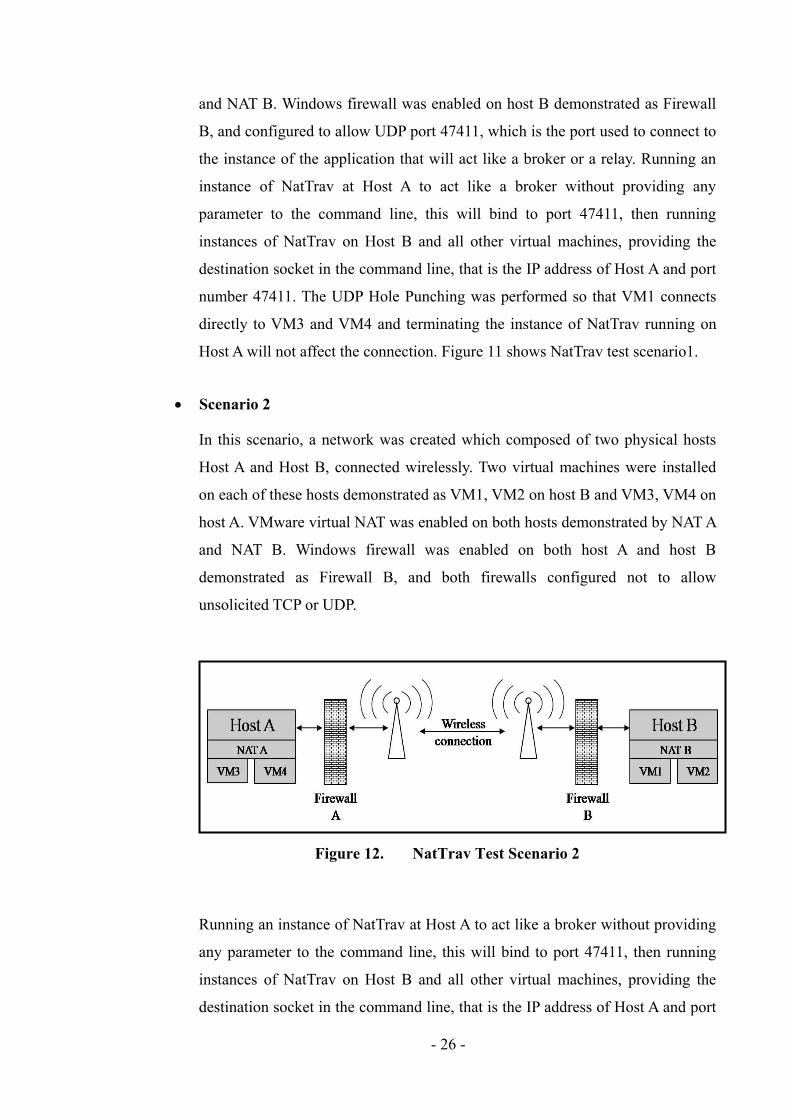
Scenario 2
In this scenario, a network was created which composed of two physical hosts
Host A and Host B, connected wirelessly. Two virtual machines were installed
on each of these hosts demonstrated as VM1, VM2 on host B and VM3, VM4 on
host A. VMware virtual NAT was enabled on both hosts demonstrated by NAT A
and NAT B. Windows firewall was enabled on both host A and host B
demonstrated as Firewall B, and both firewalls configured not to allow
unsolicited TCP or UDP.
Figure 12. NatTrav Test Scenario 2
Running an instance of NatTrav at Host A to act like a broker without providing
any parameter to the command line, this will bind to port 47411, then running
instances of NatTrav on Host B and all other virtual machines, providing the
destination socket in the command line, that is the IP address of Host A and port

- 27 -
number 47411. No connection was established, VM1, VM2 and B cannot
connect to A, but allowing UDP port 47411 on firewall A, will enable VM1 and
VM2 to connect to host A, however they can't discover VM3 and VM4.
Enabling UDP port 47411 on both firewalls allows a relayed connection between
VM1 and VM3. Figure 12 shows NatTrav test scenario2.
Scenario 3
In this scenario, a network was created which composed of three physical hosts
Host A, Host B and Host C; connected wirelessly. Host C is connected to the
network without being behind a firewall or NAT box. Two virtual machines were
installed on each of these hosts demonstrated as VM1, VM2 on host B and
VM3, VM4 on host A. VMware virtual NAT was enabled on both hosts
demonstrated by NAT A and NAT B. Windows firewall was enabled on both
host A and host B demonstrated as Firewall B, and both firewalls configured to
allow UDP port 47411. Figure 13 shows NatTrav test scenario3.
Figure 13. NatTrav Test Scenario 3
Running an instance of NatTrav at Host C to act like a broker without providing
any parameter to the command line, this will bind to port 47411, then running
instances of NatTrav on Host B and all other virtual machines, providing the
destination socket in the command line, that is the IP address of Host C and port
number 47411.UDP Hole Punching was performed and a connection was
established between VM1, VM2 on host B and VM3, VM4 on Host A, however
- 28 -
VM1 could discover and connects to VM3, VM4 on Host A, but VM2 could
only discover VM3 not VM4, which I believe is a UDP socket multi connection
issue rather than a VMware related issue.
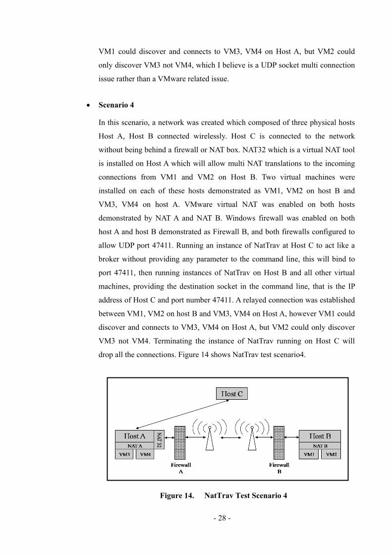
Scenario 4
In this scenario, a network was created which composed of three physical hosts
Host A, Host B connected wirelessly. Host C is connected to the network
without being behind a firewall or NAT box. NAT32 which is a virtual NAT tool
is installed on Host A which will allow multi NAT translations to the incoming
connections from VM1 and VM2 on Host B. Two virtual machines were
installed on each of these hosts demonstrated as VM1, VM2 on host B and
VM3, VM4 on host A. VMware virtual NAT was enabled on both hosts
demonstrated by NAT A and NAT B. Windows firewall was enabled on both
host A and host B demonstrated as Firewall B, and both firewalls configured to
allow UDP port 47411. Running an instance of NatTrav at Host C to act like a
broker without providing any parameter to the command line, this will bind to
port 47411, then running instances of NatTrav on Host B and all other virtual
machines, providing the destination socket in the command line, that is the IP
address of Host C and port number 47411. A relayed connection was established
between VM1, VM2 on host B and VM3, VM4 on Host A, however VM1 could
discover and connects to VM3, VM4 on Host A, but VM2 could only discover
VM3 not VM4. Terminating the instance of NatTrav running on Host C will
drop all the connections. Figure 14 shows NatTrav test scenario4.
Figure 14. NatTrav Test Scenario 4

- 29 -
4 Design
For the reasons described in section 2.5 and summarized in section 2.8, and in order to
fulfil the specification required by OneDrum, and also to meet the dissertation objectives; a
new solution was created, designed and implemented. This chapter describes the design
details.
4.1 The Requirements
The set of requirements, which this dissertation aims to implement a solution for,
are as follows:
Design and implement a NAT traversal solution which will decrease the load on
the server by decreasing the number relayed connections, but has a reasonable
scalability.
A Java based solution, because OneDrum uses JXTA framework to develop P2P
applications, and also java uses a safe environment and allows a lot of powerful
libraries like Netty which was used in the implemented solution. More details
about Netty library will be described later in this chapter.
A solution that is easy to understand by other developers.
A solution that is simple to be integrated into other P2P applications.
A solution that uses a reliable transport layer protocol TCP in all
communications; the data transfer, information message exchange and the Hole
Punching algorithm. However, using TCP in performing Hole Punching
mechanism, adds extra complexity to the Hole Punching mechanism for the fact
that TCP connection allows only binding to a specific port or sending data
through that specific port but not both. But on the other hand, reliable sessions
will be formed and that is easy to manage and eliminate the complexity needs to
be added to the unreliable UDP in order to transfer reliable data over UDP.
A solution that is tested and has been proven to be working. OneDrum has a
restricted policy concerning testing, more details are in chapter 6.
- 30 -
4.2 The NAT Traversal Approach
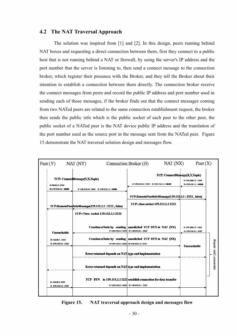
The solution was inspired from [1] and [2]. In this design, peers running behind
NAT boxes and requesting a direct connection between them, first they connect to a public
host that is not running behind a NAT or firewall, by using the server's IP address and the
port number that the server is listening to, then send a connect message to the connection
broker, which register their presence with the Broker, and they tell the Broker about their
intention to establish a connection between them directly. The connection broker receive
the connect messages from peers and record the public IP address and port number used in
sending each of those messages, if the broker finds out that the connect messages coming
from two NATed peers are related to the same connection establishment request, the broker
then sends the public info which is the public socket of each peer to the other peer, the
public socket of a NATed peer is the NAT device public IP address and the translation of
the port number used as the source port in the message sent from the NATed peer. Figure
15 demonstrate the NAT traversal solution design and messages flow.
Figure 15. NAT traversal approach design and messages flow

- 31 -
After the broker exchange NATed peers between the appropriate peers. Once a
NATed peer receives the remote peer's information from the rendezvous server, it closes
the connection with the server and start to send SYN connection request messages,
concurrently and directly between each other using the same socket address that was used
to register with the rendezvous server, The reason why they have to close the connection
with the server because in TCP, a socket cannot be used for two simultaneous connections,
so if they use different socket address in addressing the outgoing packets, NAT devices will
translate the local address used in these packets into a new public address differs from the
one recoded by the server previously and that will prevent performing the Hole Punching
method. However, there is one disadvantage of closing a connection with a peer then reuse
the same socket used in that connection to establish a new connection with another peer,
which is after closing a connection, the socket used in that connection cannot be used for
around four minutes, because after the connection closed the socket will enter the
TIME_WAIT state and according to old operating systems, any socket is in the
TIME_WAIT state cannot be reused. In newer operating systems they support the socket
reuse option so_reuse, that can be added to the application code before calling the connect
method, which allows using sockets that are in the TIME_WAIT state without having to
wait.
The idea behind both NATed peers start sending SYN connection request messages
request concurrently is to get to the situation where SYN message from NATed peer X
passes NAT X device before the SYN message from NATed peer Y reaches NAT X device,
and the SYN message from NATed peer Y passes NAT Y device before the SYN message
from NATed peer X reaches NAT Y device, in this way the NAT X device will not reject
the SYN message from NATed peer Y because the same socket used as the source
endpoint, was used in a message sent previously by X as the destination endpoint, not an
unsolicited SYN message, and at the same time, the NAT Y device will not reject the SYN
message from NATed peer X because the same socket used as the source endpoint, was
used in a message sent previously by Y as the destination endpoint, not an unsolicited SYN
message, thus depending on the operating system, one or both peers will respond with a
SYN_ACK to the other peer's SYN message, and TCP connection(s) will be established
between the two NATed peers traversing the NAT devices. In case the previously described
situation did not happen due to delays in the network for software or hardware reasons, the
two instances of the P2P application running on both NATed peers will simply try again

- 32 -
and again until the previously situation met and they successfully connected, and they
likely to succeed in the second try if they fail in the first try.
One more thing to mention about the socket reuse option, is that it doesn't consume
port numbers, because in case it is not enabled, then the peers should use new different port
numbers in contacting another peer, other than those used in contacting the server, even if
the connection with the server had been closed, and this is a port numbers consuming
process, otherwise they have to wait for around four minutes in order to get the closed
socket released from the TIME_WAIT state which is a time consuming process. It seems
like most P2P application developers are not aware of the socket reuse address option
which is crucial and recommended in P2P applications that uses Hole Punching
mechanism to traverse the NAT devices.
4.2.1 The NAT Traversal Approach Messages
Four types of messages were defined and used in the solution, as demonstrated in
figure 15.
ConnectMessage, a class which is used by the peers to register and to send a
connection request to the broker, its constructor has three parameters, the first one
is the peer ID of the initiator which is assumed to be a unique string in this solution,
the second parameter is the recipient peer ID which is assumed to be a unique
string as well, and the third parameter is the topic which is assumed to be a string.
All these three parameters help the broker to match the requests based on the fact
that the initiator and the recipient both requesting information from the broker to
connect to each other and to talk on the same topic.
RemoteEdgePeerInfoMessage, a class which is used by the broker to send the
public socket address of the remote peer to every peer requesting to be connected to
the remote pee rand talk on the same topic, its constructor has one parameter which
is of type InetSocketAddress object, holding the socket address of the remote peer.
ConnectMessage(String fromPeer, String toPeer, String topic)
RemoteEdgePeerInfoMessage(InetSocketAddress aSocketAddress)

- 33 -
ConnectionCompletedMessage(String aPeerID) a class which is used by the peers
to send their local peer ID to the remote peer when a connection established
between the two peers, in order to confirm that a successful connection was
established, it has one parameter which is of type string, holding the peer ID of the
local peer.
CloseConnectionWithMessage(String aPeerID) a class which is used by the peers
to send to the remote peer ID a close connection message, telling the remote peer to
close the connection with the initiator, rather than closing the connection locally
from the local peer, it has one parameter which is a string object holding the
remote peer ID. Although this type of message was not used in the implementation
but it adds more flexibility that can be useful to some P2P applications developed
based on this library.
4.3 The Software Design
The solution software design composed of three main packages the nettyNattTrav
package which contains the core classes of this library, the commandline package, which
contain the classes that use the library, and the test package which contain the different test
classes each of which carry out one or more test cases to test the library software
component. Figure 16 shows the nettynattrav package which contains the core classes of
the NettyNatTrav library. The dotted line shapes represent a logical grouping. It contains
four classes for the messages described earlier in this chapter, the MessageEncoder class
which is used to transform the data to be transferred into a frame, the MessageDecoder
class which is used to retrieve the data transferred back to its original form, Netty library
needs such encoder decoder classes to ensure performance, efficiency and reliability, the
EdgePeer class which responsible for creating a peer object, two peer side handlers, the
ConnectionCompletedMessage(String aPeerID)
CloseConnectionWithMessage(String aPeerID)

- 34 -
EdgePeerConnectionHandlerBroker class which handles the connections between the peer
and the broker, and the EdgePeerConnectionHandlerPeer class which handles the
connections between the peer and the other remote peers, the ConnectionBroker class
which creates a connection broker, a broker side handler, the
ConnectionBrokerConnectionsHandler class which is responsible for handling the
connections with the broker, the ConnectionRegistry class which is responsible for the
logic of the broker, the MapKey class which is used for creating keys for the connection
registry map, the Responder class which is needed to implement the call back interface
methods, more details in chapter 5.
Figure 16. nettynattrav Package
Figure 17 shows the commandline package which contain the classes that forms a
simple application that works on top of this NettyNatTrav library and uses the library
classes, the client class which is responsible for creating a peer, the server class which is
responsible for creating a broker, more details in chapter 5.
Figure 17. The commandline Package
commandline package
Server Client
nettynattrav library package
EdgePeer
EdgePeerConnectionHandlerBroker
EdgePeerConnectionHandlerPeer
Responder
ConnectionRegistry
ConnectionBrokerConnectionsHandler
ConnectionBroker
MapKey MessageDecoder
MessageEncoder
ConnectionCompletedMessag
e CloseConnectionWithMessage
ConnectMessage
RemoteEdgePeerInfoMessage

- 35 -
Figure 18 shows the test package which contains all the test classes the unit testing
classes and the integration test class, the ConnectionRegistryTest class is responsible for
testing the ConnectionRegistry class using several test cases, the MapKeyTest class is
responsible for testing the MapKey class, the EncodeDecodeMessageTest class is
responsible for testing the encoding decoding process of a message, the IntegrationTest
class is responsible for testing all of the software components working together, the
ConnectionListenerLatch class is used for the integration test to call back when an event
occurs, more details about all of these test classes in chapter 6.
Figure 18. The test Package
test package
ConnectionListenerLatch
ConnectionRegistryTest
IntegrationTest EncodeDecodeMessageTest
MapKeyTest

- 36 -
5 Implementation
This first section of this chapter will describe in details the set of requirements,
which this dissertation aims to implement a solution for these requirements. The second
section of this chapter will describe in details the design of the solution. The third section
of this chapter will describe in details how the solution was implemented, what libraries
were used in the implementation and show some parts of the code for key methods
implementation.
5.1 NettyNatTrav
This section will describe and give in details what are the libraries that have been
used and for what reasons they have been chosen. The solution was implemented in java
using the Netty library for connection handling instead of the standard NIO library. The
next section will describe in details the Netty library.
5.1.1 Netty Library
It is a library that provides an asynchronous event driven network application
framework and tools for rapid development of maintainable high performance and high
scalability protocol servers and clients. Netty is a NIO client server framework which
enables quick and easy development of network applications such as protocol servers and
clients. It greatly simplifies and streamlines network programming such as TCP and UDP
socket server. Quick and easy doesn't mean that a resulting application will suffer from
maintainability or a performance issue. Netty has been designed carefully with the
experiences earned from the implementation of a lot of protocols such as FTP, SMTP,
HTTP, and various binary and text-based legacy protocols. As a result, Netty has succeeded
to find a way to achieve ease of development, performance, stability, and flexibility
without a compromise. Figure 19 shows Netty Framework. Choosing Netty to be used in
the implemented solution was a right choice, for the features it has and the facilities it
supports, also the amount of complexity it rounds up which simplifies the code, and speeds
up the application development, but still at the same time powerful and capable.

- 37 -
Other interesting features of Netty that make it the best choice to use as a
framework to develop P2P applications since it was designed and written from scratch to
provide the best experience in network application development, can be summarised as:
Design Unified API for various transport types blocking and non blocking socket, also it is
based on a flexible and extensible event model which allows clear separation of concerns,
also it is highly customizable thread model single thread, one or more thread pools such as
SEDA True connectionless datagram socket support, also it comes with well documented
Javadoc, user guide and examples, that make it easy to use and understand. In addition to
that it supports encryption in SSL/TLS and StartTLS for more security.
Figure 19. Netty Framework
Other features to mention here like less resource consumption, minimized
unnecessary memory copy, robustness, no more OutOfMemoryError due to fast, slow or
overloaded connection, no more unfair read / write ratio often found in a NIO application
under high speed network, also it runs OK in a restricted environment such as Applet and
Google Android [7].
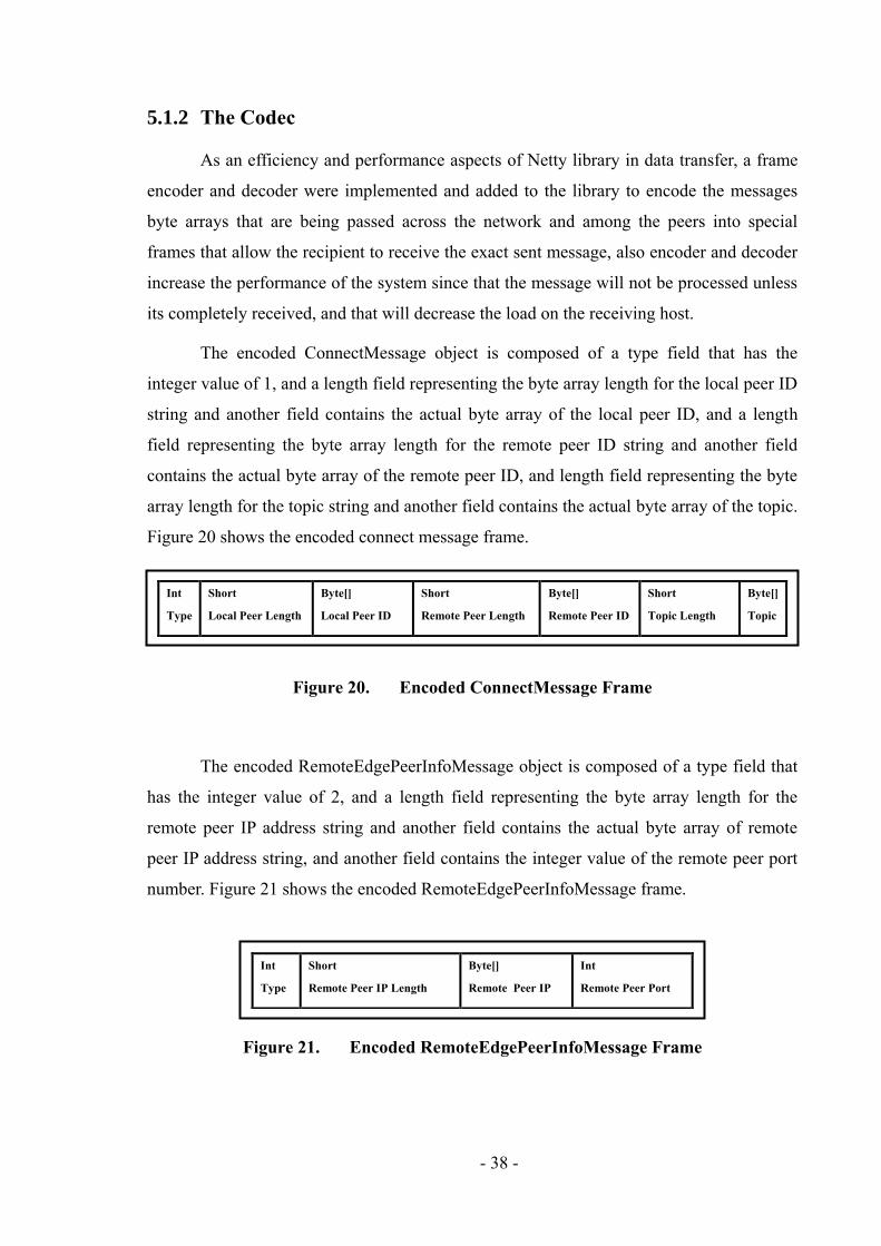
- 38 -
5.1.2 The Codec
As an efficiency and performance aspects of Netty library in data transfer, a frame
encoder and decoder were implemented and added to the library to encode the messages
byte arrays that are being passed across the network and among the peers into special
frames that allow the recipient to receive the exact sent message, also encoder and decoder
increase the performance of the system since that the message will not be processed unless
its completely received, and that will decrease the load on the receiving host.
The encoded ConnectMessage object is composed of a type field that has the
integer value of 1, and a length field representing the byte array length for the local peer ID
string and another field contains the actual byte array of the local peer ID, and a length
field representing the byte array length for the remote peer ID string and another field
contains the actual byte array of the remote peer ID, and length field representing the byte
array length for the topic string and another field contains the actual byte array of the topic.
Figure 20 shows the encoded connect message frame.
Figure 20. Encoded ConnectMessage Frame
The encoded RemoteEdgePeerInfoMessage object is composed of a type field that
has the integer value of 2, and a length field representing the byte array length for the
remote peer IP address string and another field contains the actual byte array of remote
peer IP address string, and another field contains the integer value of the remote peer port
number. Figure 21 shows the encoded RemoteEdgePeerInfoMessage frame.
Figure 21. Encoded RemoteEdgePeerInfoMessage Frame
Int
Type
Short
Local Peer Length
Byte[]
Local Peer ID
Short
Remote Peer Length
Byte[]
Remote Peer ID
Short
Topic Length
Byte[]
Topic
Int
Type
Short
Remote Peer IP Length
Byte[]
Remote Peer IP
Int
Remote Peer Port

- 39 -
The encoded ConnectionCompletedMessage object is composed of a type field that
has the integer value of 3, and a length field representing the byte array length for the local
peer ID string and another field contains the actual byte array of local peer ID string.
Figure 22 shows the encoded ConnectionCompletedMessage frame.
Figure 22. Encoded ConnectionCompletedMessage Frame
The encoded CloseConnectionWithMessage object is composed of a type field that
has the integer value of 4, and a length field representing the byte array length for the
remote peer ID string and another field contains the actual byte array of remote peer ID
string. Figure 23 shows the encoded CloseConnectionWithMessage frame.
Figure 23. Encoded CloseConnectionWithMessage Frame
5.1.3 The Library Structure
The nettynattrav package composed of the four messages objects described in the
previous section, the MapKey object, the Edgepeer and its connection handlers objects, the
Broker and its connections handler objects, ConnectionRegistry object and the responder
object of the Broker class, the EdgePeer class and also a handler for the Broker that
handles the connections and events for the broker, and another handler for the EdgePeer
that handles the connections and events for the peer.
The Broker class is used to create a connection broker and initiate a connection
registry which is responsible for matching requests and returning required information, the
broker has a channel with two cached thread pools, and a channel pipeline which holds all
the handlers and the codec to perform their actions on the data being transferred over the
Int
Type
Short
Local Peer Length
Byte[]
Local Peer ID
Int
Type
Short
Local Peer Length
Byte[]
Local Peer ID
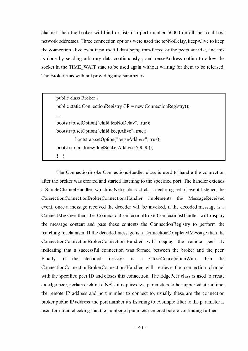
- 40 -
channel, then the broker will bind or listen to port number 50000 on all the local host
network addresses. Three connection options were used the tcpNoDelay, keepAlive to keep
the connection alive even if no useful data being transferred or the peers are idle, and this
is done by sending arbitrary data continuously , and reuseAddress option to allow the
socket in the TIME_WAIT state to be used again without waiting for them to be released.
The Broker runs with out providing any parameters.
public class Broker {
public static ConnectionRegistry CR = new ConnectionRegistry();
…
bootstrap.setOption("child.tcpNoDelay", true);
bootstrap.setOption("child.keepAlive", true);
bootstrap.setOption("reuseAddress", true);
bootstrap.bind(new InetSocketAddress(50000));
} }
The ConnectionBrokerConnectionsHandler class is used to handle the connection
after the broker was created and started listening to the specified port. The handler extends
a SimpleChannelHandler, which is Netty abstract class declaring set of event listener, the
ConnectionConnectionBrokerConnectionsHandler implements the MessageReceived
event, once a message received the decoder will be invoked, if the decoded message is a
ConnectMessage then the ConnectionConnectionBrokerConnectionsHandler will display
the message content and pass these contents the ConnectionRegistry to perform the
matching mechanism. If the decoded message is a ConnectionCompletedMessage then the
ConnectionConnectionBrokerConnectionsHandler will display the remote peer ID
indicating that a successful connection was formed between the broker and the peer.
Finally, if the decoded message is a CloseConnebctionWith, then the
ConnectionConnectionBrokerConnectionsHandler will retrieve the connection channel
with the specified peer ID and closes this connection. The EdgePeer class is used to create
an edge peer, perhaps behind a NAT. it requires two parameters to be supported at runtime,
the remote IP address and port number to connect to, usually these are the connection
broker public IP address and port number it's listening to. A simple filter to the parameter is
used for initial checking that the number of parameter entered before continuing further.

- 41 -
If the parameters were entered correctly then the edge peer will connect to the
broker using the connect method that requires two parameters to be passed to it, the remote
IP address and the remote port number, the local source port is not specified and it will be
chosen arbitrarily from the available port numbers pool.
public class ConnectionConnectionBrokerConnectionsHandler extends
SimpleChannelHandler {
public void messageReceived(ChannelHandlerContext ctx, MessageEvent e)
throws Exception {
…. (Check the message received and performs the relative action)
….}
}
The EdgePeer has a channel with two cached thread pools, and a channel pipeline
which holds all the handlers and the codec to perform their actions on the data being
transferred over the channel. It also define an inner interface EventListener that has three
methods, messageEventCallBack, isConnectet and errorEventCallBack, methods that used
as acall back technique when an event occurs theses methods are invoked to call the
EdgePeer class back.
Public class EdgePeer {
public static ChannelFuture connect(String aRemoteHostAddress,
int aRemotePortNumber) {...}
public static ChannelFuture connect(String aRemoteHostAddress,
int aRemotePortNumber, int aLocalPortNumber) {...}
}
Three connection options were used the tcpNoDelay, keepAlive to keep the
connection alive even if no useful data being transferred or the peers are idle, and this is

- 42 -
done by sending arbitrary data continuously , and reuseAddress to allow the socket in the
TIME_WAIT state to be used again without waiting for them to be released. The EdgePeer
also implements another connect method that requires three parameters to be passed to it,
the remote IP address and the remote port number and the local source port which helps in
performing the Hole Punching mechanism with the aid of socket reuse option. The
EdgePeerHandlerBroker and EdgePeerHandlerPeer classes are used to handle the
connection after the edge peer was connected with a remote host on the specified port.
The handlers' classes extend a SimpleChannelHandler and each of them has a
constructor that uses a listener which is the client's anonymous inner class EventListener
which is a call back interfaces with three main methods that make it easier to test. The
handler implements three methods described earlier in this chapter. The channelConnected
event is used display the remote peer information and to create and send a
ConnectionCompletedMessage to the other peer. The messageReceived event is used to
connect to the remote peer once the public socket for that remote peer through
RemoteEdgePeerInfoMessage object, and then closes the connection with the broker, if an
exception occurs, due to the remote peer not available or the network fails. The
exceptionCaught is used to retry connecting to the remote peer for a specified number of
times, five times was set by default.
public class EdgePeerConnectionsHandlerBroker extends SimpleChannelHandler {
public EdgePeerConnectionsHandler(EdgePeer.EventListener
aClientEventListener, int aRemotePort,String aLocalPeerID) {..}
public void channelConnected(ChannelHandlerContext ctx,
ChannelStateEvent e){..}
public void messageReceived(ChannelHandlerContext ctx, MessageEvent e)
throws Exception {..}
public void exceptionCaught(ChannelHandlerContext ctx, ExceptionEvent e)
throws Exception {….
}
}
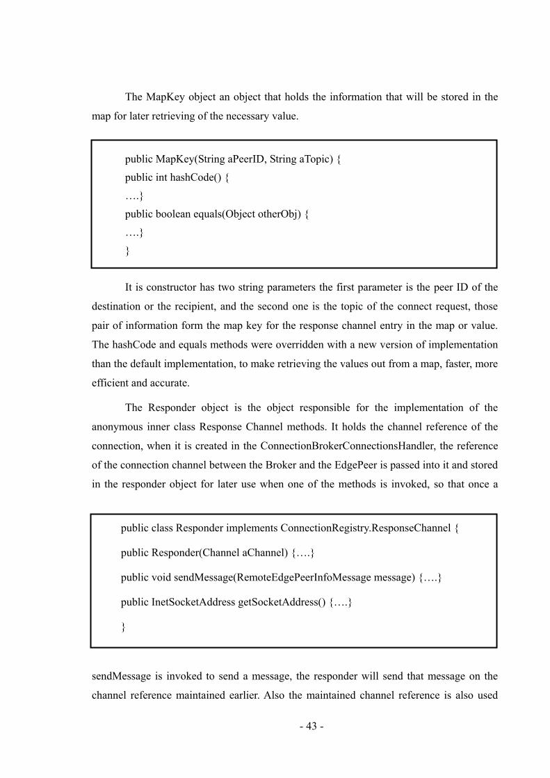
- 43 -
The MapKey object an object that holds the information that will be stored in the
map for later retrieving of the necessary value.
public MapKey(String aPeerID, String aTopic) {
public int hashCode() {
….}
public boolean equals(Object otherObj) {
….}
}
It is constructor has two string parameters the first parameter is the peer ID of the
destination or the recipient, and the second one is the topic of the connect request, those
pair of information form the map key for the response channel entry in the map or value.
The hashCode and equals methods were overridden with a new version of implementation
than the default implementation, to make retrieving the values out from a map, faster, more
efficient and accurate.
The Responder object is the object responsible for the implementation of the
anonymous inner class Response Channel methods. It holds the channel reference of the
connection, when it is created in the ConnectionBrokerConnectionsHandler, the reference
of the connection channel between the Broker and the EdgePeer is passed into it and stored
in the responder object for later use when one of the methods is invoked, so that once a
public class Responder implements ConnectionRegistry.ResponseChannel {
public Responder(Channel aChannel) {….}
public void sendMessage(RemoteEdgePeerInfoMessage message) {….}
public InetSocketAddress getSocketAddress() {….}
}
sendMessage is invoked to send a message, the responder will send that message on the
channel reference maintained earlier. Also the maintained channel reference is also used

- 44 -
when the getSocketAddress method is invoked; this method will return the remote socket
address used on the channel formed between the connected peer and the broker.
The ConnectionRegistry object is used by the connection broker; it is responsible
for registering the incoming requests from peers, and checks these request messages for a
mach, and once the match occurs it will invoke the ResponseChannel anonymous inner
class methods send and getSocketAddress.
First it initiates a map object that has MapKey object as a key for the corresponding
value which is the ResponseChannel object. When a connection request from a peer is
received via a ConnectMessage object, it gets from the message the destination peer ID
and the topic which forms the MapKey, and check if this key corresponds to a matching
key that has been stored earlier in the map if so then send then it will send each remote
peer the peer, the public addresses of the other address, using the ResponseChannel object
stored in the map, otherwise if the key does not corresponds to a matching key then it store
this key in the map.
public class ConnectionRegistry {
Map<MapKey,ResponseChannel> connectionRegistryMapTable = new
HashMap<MapKey, ResponseChannel> ();
public void registerConnection(ConnectMessage connectMessage,
ResponseChannel responseChannel) {….}
public interface ResponseChannel {
public void sendMessage (RemoteEdgePeerInfoMessage
emoteEdgePeerInfoMessage);
InetSocketAddress getSocketAddress(); }}
5.2 The Sample Application
The command line package contains the classes that form the application that
works on top of this NettyNatTrav library and uses the library classes. The server class
which is responsible for creating a broker will only create a new ConnectionBroker object
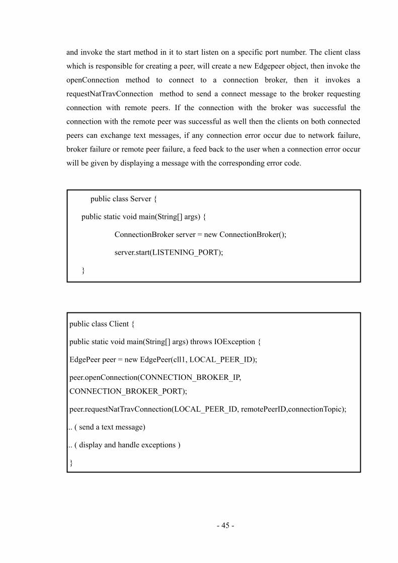
- 45 -
and invoke the start method in it to start listen on a specific port number. The client class
which is responsible for creating a peer, will create a new Edgepeer object, then invoke the
openConnection method to connect to a connection broker, then it invokes a
requestNatTravConnection method to send a connect message to the broker requesting
connection with remote peers. If the connection with the broker was successful the
connection with the remote peer was successful as well then the clients on both connected
peers can exchange text messages, if any connection error occur due to network failure,
broker failure or remote peer failure, a feed back to the user when a connection error occur
will be given by displaying a message with the corresponding error code.
public class Server {
public static void main(String[] args) {
ConnectionBroker server = new ConnectionBroker();
server.start(LISTENING_PORT);
}
public class Client {
public static void main(String[] args) throws IOException {
EdgePeer peer = new EdgePeer(cll1, LOCAL_PEER_ID);
peer.openConnection(CONNECTION_BROKER_IP,
CONNECTION_BROKER_PORT);
peer.requestNatTravConnection(LOCAL_PEER_ID, remotePeerID,connectionTopic);
... ( send a text message)
... ( display and handle exceptions )
}

- 46 -
6 Testing
Two types of tests were performed, a practical test which involved building a small
network with NATed peers, and a software test using JUnit4.0 library for unit testing and
integration test. The next two sections will give more details about both of these tests.
6.1 Practical Experiment
During this testing process a small network was built to simulate two peers running
behind two different NAT devices using private LAN addresses, and a public connection
broker. All hosts are running Windows XP SP2 operating system. Figure 24 shows the built
network topology The two NATed peers connects to the broker first, passing their
information, then once a peer gets the necessary data back from the broker, it closes its
connection with the broker and use the same local socket address used to connect with the
broker, to connect to the remote NATed peer. Both NATed peers will start sending TCP
SYN messages concurrently, if they succeed then only one connection will be established
by the TCP three way handshake, if they fail they will try again until the succeed.
Figure 24. Library Practical Test

- 47 -
As shown in the figure 24, two NATed peers peer A and Peer B are running behind
NAT devices, NAT A and NAT B respectively, peer A uses a private LAN IP address
10.0.0.2 and peer B uses a private LAN IP address 127.16.0.2. NAT A uses a public IP
address 139.153.254.178 on its WAN port and a local IP address 10.0.0.1 on its wireless
LAN port, while NAT B uses a public IP address 139.153.254.179 on its WAN port and a
local IP address172.16.0.1 on its wireless LAN port. The connection broker is using a
public address 139.153.254.89 and all peers contact this broker, requesting about remote
peers public addresses, once those peers got the requested information they start trying to
connect to each other simultaneously, while their connection with the broker is terminated.
6.2 Software Testing
During this testing process, new skills were learned in testing a software using
JUnit to perform unit testing and integration testing. One of these skills is mocking up the
interfaces, using a fake implementation in the test class to check all different behaviours of
the classes being tested at once, rather than running the class several times to try different
inputs and inspects the results.
6.2.1 Unit testing
Unit testing is a testing technique which is used to test the software component
individually and make sure that they perform their work properly. Some times it is not
feasible to test these individual component unless creating a virtual environment in the test
class and possibly mock up some interfaces used to invoke methods when events occurs.
The EncodeDecodeMessageTest is a unit test class used to test the Encoder/
Decoder objects. It starts by creating three different types of messages, ConnectMessage,
RemoteEdgePeerInfoMessage, and CLoseConnectionWithMessage, then creates a
MessageEncoder object and a MessageDecoder object, then it performs three tests using
three test methods, the testConnect which encodes the ConnectMessage using the Encoder
object then it decodes it using the decoder object, then it performs a set of asserts
statements to check the contents of the decoded message matches the original
ConnectMessage object that was created in the test class and encoded. The testRemote

- 48 -
method is used to test the encoding and decoding process of a
RemoteEdgePeerInfoMessage object in the same way as testConnect method, and the
testClose method is used to test the encoding and decoding process of a
CloseConnectionWithMessage object in the same way as testConnect method. Figure 25
shows EncodDecodMessagetest eclipse screenshot.
Figure 25. EncoderDecoderTest Screenshot
The MapKeyTest is a unit test class used to test the new overridden implementation
of the equals and hashCode methods of the MapKey object. It creates three
ConnectMessaqge objects, two of them only are identical, then it creates three MapKey
objects based on the three ConnectMessage object created earlier, using the destination
peer ID and the topic used in the ConnectMessage objects, this will form two identical
MapKey objects. Then it checks the equal's method by asserting the identical MapKey
objects and expecting the result to be true, while expecting the result to be false by
asserting one of those two identical MapKey objects with the third MapKey object. The
hashCode method is tested by asserting the hash codes value of the identical the identical
MapKey objects and expecting the result to be equal, while expecting the result to be

- 49 -
unequal by asserting one of those two identical MapKey objects hash code value with the
third MapKey object hash code value. Figure 26 shows MapKeyTest eclipse screenshot.
Figure 26. MapKeyTest Screenshot
The ConnectionRegistryTest as shown in figure 27, is a unit test class used to test
the ConnectionRegistry object behaviour. It creates, a ConnectionRegistry object and
several different ConnectMessage objects composed of three different peers, it also creates
and initializes three socket addresses, three mocked up ResponseChannel objects
implementation, and three ArrayList objects, all of which corresponds to one of the
specified peers. The SendMessage method implementation is mocked up using a new
implementation which adds the message to be sent to a specified peer to its corresponding
ArrayList object, while the new implementation of the getSocketAddress method will
return the corresponding socket address previously created and initialized. Several test
cases were performed to check variety of scenarios like two peers trying to connect to each
other on the same topic, two peers trying to connect to each other on different topic, two
peers trying to connect to each other on different two topics and many other test cases.

- 50 -
Figure 27. ConnectionRegistryTest Screenshot
6.2.2 Integration Testing
Integration testing is a testing technique which is used to test the software in whole
as one entity and make sure that all of its components are well bound to perform its work
properly. Some method takes some time to process and perform its operation before it
returns results. To assure that is no other operation or method that needs the result variable
to perform its operations will get a null value because the first method did not updated the
value of the shared variable, a count down latch was used to achieve this task.
ConnectionListenerLatch object implements the EventListener inner anonymous
class methods messageEventCallBackand, errorEventCallback, isConnected, and creates a
CountDownLatch which is a new approach replaces the deprecated Thread.wait () and
Thread.notify () which have been deprecated for the risk of getting a deadlock. The
CountDownLatch uses a count down timer that will be activated when a specified event
occurs, in order to notify a waiting thread, the count down timer can be configured in the

- 51 -
awit() method, which will suspend a thread and set the timer. The eventAwit method
create and initialise a Boolean check variable it will return true only if the timer is
activated. When the countdown method is invoked in the messageEventCallBack method,
it will activate the timer, set the Boolean check variable to true, and after the specified time
elapses, the thread will enter the ready state. The integration test class creates and
initializes five ConnectionListenerLatch objects, five Client objects and a Server object.
The Server's start method will be invoked to bind the server to a specified port number,
then each of the five Client objects will try to connect to the server by invoking the
openConnection method, supporting the servers IP address and port number, the each
Client object will send ConnectionRequestMessage by invoking the
requestNatTravConnection method, then perform assertion based on the value of the
Boolean variable of each Client object CountDownLatch which will return true if the
countDown method has been invoked in the messageEventCallBack method, which in turn
will only be invoked from the MessageReceived event on each Client object when a
RemoteEdgePeerInfoMessage is received, other wise it will return false, to check that the a
client receive the appropriate information from the server. In order to check that there
exists a server listening to the port that the client is trying to connect to, assertions were
made based on the isConnected method which will return true if there is no connection
error, otherwise it will return false. Figure 28 shows IntegrationTest eclipse screenshot.
Figure 28. IntegrationTest Screenshot

- 52 -
7 Conclusion
7.1 Summary
According to the specification OneDrum required in a NAT traversal solution,
researches on different Hole Punching solutions were undergone, since Hole Punching
method is a simple, powerful and cost effective approach, these solutions have some points
of strength as well as weaknesses. According to OneDrum company requirements, the NAT
traversal solution proposed by this dissertation for Cone based NATs was successfully
implemented using java, with the aid of Netty library and the TCP Hole Punching was
performed, and tested.
7.2 Evaluation
Researches on different Hole Punching solutions were made; these solutions have
some points of strength as well as weaknesses. NatTrav library was tested thoroughly as
described in chapter 3. According to OneDrum company requirements, the NAT traversal
solution proposed by this dissertation for Cone based NATs was successfully implemented
using java, with the aid of Netty library and the TCP Hole Punching was performed
successfully as described in chapter 4 and 5, and tested as described in chapter 6.
The implemented solution was successful, according to the practical and software
test achieved as demonstrated in chapter 6. The implementation focused on the cone based
NATs for the reason it is widely used by most NAT devices vendors.
Choosing Netty library was a good choice, because it absorbs a lot of the
connections management complexity, and the latest versions of Netty support UDP in
addition to TCP, which is advantageous to perform UDP Hole Punching if needed.
Although implemented solution did not tackle the symmetric NATs, which requires
more sophisticated code to predict the translation by monitoring couple of previous
translations for the same peer and calculate the expected translation to be used next, which
adds more unnecessary complexity to the implementation, according to [9], most NAT
devices brands use cone based translation, only limited NAT devices, not even widely used
brands, use Symmetric translation, and most NAT manufacturers are moving away from

- 53 -
using the symmetric behaviour in their NAT devices. Also, the implemented solution does
not support relaying of the connections as a last resort if the Hole Punching mechanism
failed, but that is unnecessary since it was implemented to be integrated in JXTA to
develop P2P applications, and JXTA relay all the connections.
The implemented solution uses socket reuse address option, which might sounds to
be problematic for the first instance in terms of data loss or multiplexing or even security
attacks, but since at the network layer, all packets headers contain the protocol field,
destination and source IP address fields, in addition to the destination and source port
numbers obtained from the transport layer, it is very unlikely that another packet in the
network has the same addresses mentioned, however, if that was the case it will cause
problems such as data loss. The solution does not have any security aspects implemented,
but Netty support encryption using SSL/TLS and StartTLS as described in 5.1.1.
The implemented solution uses concurrent TCP Hole Punching, and according to
the practical test described in 6.1, running WireShark as shown in figure 29, on one of the
NATed peers showed that only one TCP three way hand shake connection established,
although there were multiple SYN messages sent from both peers, since the same peers'
sockets are being used in addressing both of the concurrent SYN messages.
Figure 29. WireShark Screenshot

- 54 -
7.3 Future Work
Due to the time constrains, some features could have been added to the
implemented solution, such as adding relay support, to make the implemented solution
more useful with frameworks other than JXTA.
Add security capability is recommended in future work, with the fact that Netty
library support encryption as described in 5.1.
The possibility to develop this solution without using socket reuse address option
can be considered as a good improvement, to eliminate the concerns about using the socket
reuse address option and also to make the solution work on old operating system which
doesn't support the socket reuse option.
Adding support for UDP Hole Punching might be a good improvement, but it is
more difficult to manage the UDP sessions than TCP, by adding special header fields to the
UDP packet, which will make the UDP packets not as efficient as the standard UDP in
multimedia streaming, but just for completeness.
Adding a symmetric NAT support might be a good improvement as well, but not
recommended for the reasons described in the previous section.

- 55 -
References
[1] Bryan Ford, et al, Peer-to-Peer Communication Across Network Address Translators.
[2] J.L. Eppinger. TCP Connections for P2P Apps: A Software Approach to Solving the
NAT Problem. reports-archive.adm.cs.cmu.edu, 2005.
[3] J. Rosenberg, J. Weinberger, C. Huitema, and R. Mahy. STUN - Simple Traversal of
User Datagram Protocol (UDP) Through Network Address Translators (NATs).RFC
3489 (Proposed Standard), March 2003.
[4] J. Rosenberg et al, Traversal Using Relays around NAT (TURN): Relay Extensions to
Session Traversal Utilities for NAT (STUN), Internet Draft, October 2008, link:
http://tools.ietf.org/id/draft-ietf-behave-turn-11.txt
[5] Paul Francis Saikat Guha. STUNT, Simple Traversal of UDP Through NATs and TCP
too, link: http://nutss.gforge.cis.cornell.edu/stunt.php
[6] JXTA, Sun Microsystems, Java-based P2P Framework, link: http://www.jxta.org
[7] Netty Library, link: http://jboss.org/netty
[8] UPnP. Universal plug 'n' play group, link: http://www.upnp.org
[9] http://tools.ietf.org/html/draft-jennings-midcom-stun-results-02
[10] SA Baset and H Schulzrinne. An analysis of the skype peer-to-peer internet telephony
protocol. Columbia University, New York, NY, 2004
[11] Kelaskar, M., et al A Study of Discovery Mechanisms for Peer-to-Peer Application.
2002
[12] Wikipedia, the free encyclopaedia, http://en.wikipedia.org
[13] http://www.answers.com
Related Documents


![[E6]2012. netty internals](https://static.cupdf.com/doc/110x72/5562c0fed8b42a13618b5062/e62012-netty-internals.jpg)


