Progress In Electromagnetics Research B, Vol. 40, 185–200, 2012 IMPLEMENTATION OF RFID AND BLUETOOTH TECH- NOLOGY FOR DATA TAGGING AND TRANSMISSION TO POINT OF SALE M. B. Roslee * and T. W. Lee Faculty of Engineering, Multimedia University, Jalan Multimedia, Cyberjaya 63000, Malaysia Abstract—The design of wireless technology which involves radio frequency identification (RFID) and Bluetooth technology for tagging and transmission of data that will be applied to point of sale (POS) is presented. A complete POS circuitry system has been designed to allow certain item to be a tag easily identified and localized. This is implemented by using RFID technology which will communicate with personal computer (PC) either through Ethernet or Wifi connection. An Impinj RFID reader and Bluetooth mobile phone are selected in the proposed POS system. Matlab simulation has been performed for RFID transceiver part and Bluetooth data transmission. A prototype software is developed to interface the Impinj RFID reader through the Ethernet connection. Additionally, a data encryption from Bluetooth is paired with PC to achieve a secure and simple pairing feature when customer transaction is performed. It involves hardware and software implementation. Moreover, in simulation result, a double side band modulation is used to design the RFID reader for better item tagging. The results show the feasibility of using this design for POS and achieving very good read ranges. Finally, Bluetooth system enables fast transaction and makes purchase securely by using the proposed asymmetric algorithm. 1. OVERVIEW Point of sale (POS) system is referred to a location where the transaction is performed at mall, library, etc. Nowadays, many country businesses are growing, that leads to a lot of transaction required at POS system. The common technology uses a barcode system Received 21 February 2012, Accepted 6 April 2012, Scheduled 18 April 2012 * Corresponding author: Mardeni Bin Roslee ([email protected]).

Welcome message from author
This document is posted to help you gain knowledge. Please leave a comment to let me know what you think about it! Share it to your friends and learn new things together.
Transcript

Progress In Electromagnetics Research B, Vol. 40, 185–200, 2012
IMPLEMENTATION OF RFID AND BLUETOOTH TECH-NOLOGY FOR DATA TAGGING AND TRANSMISSIONTO POINT OF SALE
M. B. Roslee* and T. W. Lee
Faculty of Engineering, Multimedia University, Jalan Multimedia,Cyberjaya 63000, Malaysia
Abstract—The design of wireless technology which involves radiofrequency identification (RFID) and Bluetooth technology for taggingand transmission of data that will be applied to point of sale (POS)is presented. A complete POS circuitry system has been designed toallow certain item to be a tag easily identified and localized. This isimplemented by using RFID technology which will communicate withpersonal computer (PC) either through Ethernet or Wifi connection.An Impinj RFID reader and Bluetooth mobile phone are selected inthe proposed POS system. Matlab simulation has been performed forRFID transceiver part and Bluetooth data transmission. A prototypesoftware is developed to interface the Impinj RFID reader through theEthernet connection. Additionally, a data encryption from Bluetoothis paired with PC to achieve a secure and simple pairing feature whencustomer transaction is performed. It involves hardware and softwareimplementation. Moreover, in simulation result, a double side bandmodulation is used to design the RFID reader for better item tagging.The results show the feasibility of using this design for POS andachieving very good read ranges. Finally, Bluetooth system enablesfast transaction and makes purchase securely by using the proposedasymmetric algorithm.
1. OVERVIEW
Point of sale (POS) system is referred to a location where thetransaction is performed at mall, library, etc. Nowadays, many countrybusinesses are growing, that leads to a lot of transaction requiredat POS system. The common technology uses a barcode system
Received 21 February 2012, Accepted 6 April 2012, Scheduled 18 April 2012* Corresponding author: Mardeni Bin Roslee ([email protected]).

186 Roslee and Lee
at POS [1–3]. Unfortunately, as we observed from shopping malls,the POS terminal becomes crowded easily [4–6], especially when the“Special Offers” is launched. Thus, it was motivated to overcome thisproblem by using RFID and Bluetooth technology for item tagging anddata transmission purpose.
Unlike barcode system, both new technologies stated do notrequire any line of sight. RFID technology can be used for itemtagging and identify each individual item. It also allows a unique serialnumber product authentication to be implemented. For Bluetoothtechnology, it is used for data transaction purpose. The RFIDtechnology will involve reader, antenna, and tag. The reader will actslike a transmitter and receiver which will communicate with the tagand personal computer. Each tag will carry a unique tracking identifiercoding. Thus, with the item tagged with RFID tag and passing throughthe RFID reader, the specific item will be easily recognized and theirlocation identified. Besides this, Bluetooth technology becomes verycommon on our mobile phone. Many mobile phones will acquireBluetooth communication link [7–9]. With this kind of technology,we can perform the authorization of transaction at POS system.
In this work, using both of the technologies can make the POSsystem faster and convenient. There are researches on RFID readercommunicates with tag by using ‘Low Level Reader protocol (LLRP)’,type of tag used, type of modulation applied to the reader and stackof Bluetooth system through protocol [10–12].
In this implementation, Impinj RFID reader and Bluetooth mobilephone are selected for POS system, and Matlab simulation has beenperformed for RFID transceiver part and Bluetooth data transmission.As a result, an amplitude-shift keying (ASK) signal is obtained whenthe reader and tag communicate with each other. The Bluetoothmobile phone for frequency hopping on Matlab simulation has beenstudied. The RFID reader and tag are obtained from Impinj foranalysis purpose. Besides, a connection between PC and Bluetoothmobile phone also has been performed and investigated.
2. IMPLEMENTATION OF RFID AND BLUETOOTHTECHNOLOGY
As we enter the new decade of technology, business is growing rapidly,which results in a busy POS system, and bar codes system cannotkeep up the pace [13–15]. In this work, a RFID and Bluetooth areproposed as a solution. The RFID system involves reader, tag, andantenna able to keep track the item. First, the tag will be placedon each item inside the inventory. In order to communicate with

Progress In Electromagnetics Research B, Vol. 40, 2012 187
the tag, a RFID reader is required. The RFID reader transmits thesignal and waits until the reflected signal from the tag back to theRFID reader via the antenna. This technique of tag communicationuses backscatter modulation. The proposed POS system by usingBluetooth technology can involve mobile phone and computer laptopas a transaction purpose. The proposed design of the overall POS
Customer
Tag
Antenna for tag &
reader
RFID reader
Customer/Admin/Cashier
PC support with Bluetooth
Mobilephone
Figure 1. POS system using RFID and Bluetooth technology.
Figure 2. Flow chart of overall implementation.

188 Roslee and Lee
system is shown in Figure 1. Figure 2 shows the flow chart of overallimplementation of this POS system.
2.1. Circuit Design: RFID Tag with Reader Communication
This circuit design consists of two parts, Impinj RFID reader andtag. The passive tags are produced by Impinj which encodes thebackscattered data as FM0 baseband at the data rate on the passivetag. The reader then commands the encoding choice result of the ASKmodulation. As shown in Figure 3 of the Matlab simulink, the readercommunicates with the tag using FM0 baseband data modulation. Itcan be observed from the figure that there are two pulse generators(positive and negative) which will act as a bi-phase space encoding.These pulses then will invert the baseband phase at every symbol
From reader transmitted out signal via free space
Tag absorption/reflection signal to reader receiver
Figure 3. RFID tag to reader communication using baseband FM0data modulation.
Figure 4. Single side band — Amplitude shift keying modulation(SSB-ASK).

Progress In Electromagnetics Research B, Vol. 40, 2012 189
boundary. The data-0 has an additional mid-symbol phase inversionwhich results in the FM0 baseband generated. The FM baseband playsan important role in the ASK modulation between the tag and thereader. Since RFID tag is a passive type which does not require anypower source, with implementation of ASK modulation, it can obtainthe energy or power by converting the electromagnetic energy emittedby the reader into the DC power level. This is required to activatethe tag. ASK modulation can also be easily detected with a simpleenvelope detector. The reader modulation uses a Single side band —amplitude shift keying modulation (SSB-ASK) as shown in Figure 4.This means that the I/Q modulator consists of two frequencies whichare carrier frequency, fc, and modulating frequency, fm, thus this willimprove the signal spectrum efficiently.
However, in order to track the item, the tag requires a code toidentify the product. RFID systems use the standards developed byEPCglobal Inc. The electronic product code (EPC) is the namingconvention used in programming of the tag. EPC allows each tag tohave a unique code so that each tag can be recognized individually. Thefollowing Figure 5 is the breakdown of the code convention. Throughthis EPC number, the item can be easily associated with RFID passivetag.
When the reader and tag are able to communicate with each other,it is important to take the consideration on timing. Figure 6 shows thelink timing between the reader and a single tag. The period of T2
indicates the timing/period of the tag in the reply or acknowledges(ACK) states. If the two systems communicate with each other,a response of acknowledgement will be definitely needed when theproblem or error is found.
If the tag facing an invalid command, an invalid EPC numberor collision will occur, then it will enter the ACK states or enter thereply states. The reader must transmit a continuous wave, CW withinthe duration to change the data symbol parameters for a subsequentinventory round. Within this CW period, this link will become reset.
01 0001B6F 0000F3 00002A9C3
Header DomainManager
ObjectClass
SerialNumber
Figure 5. Example of EPC number program inside the RFID tag.

190 Roslee and Lee
Figure 6. Reader and tag link timing.
Receiver
Transmitter
Figure 7. Gaussian frequency shift keying (GFSK) and multiplefrequency shift keying (M-FSK) for Bluetooth interface.
2.2. Circuit Design: Bluetooth Transceiver
Figure 7 shows a circuit design for Bluetooth wireless data linkbetween transmitter and receiver. Bluetooth is a short-range radiolink technology that operates in the 2.4GHz Industrial, Scientific, and

Progress In Electromagnetics Research B, Vol. 40, 2012 191
EXIT
EXIT
Figure 8. FM0 generator state diagram with symbols.
Medical (ISM) band. It uses modulation signals for Gaussian frequencyshift keying (GFSK) over a radio channel with maximum capacityof 1Mbps. The purpose of the frequency hopping over a 79MHzfrequency range is to avoid interference with other devices transmittingin the band. In addition, the sender divides the transmission timeinto 625-microsecond slots and uses a new hop frequency for each slot.Although the data rate is only 1 Mbps, a much larger bandwidth of79MHz is required to simulate the frequency hopping effects. A BinaryCyclic Encoder block is used for the error correction encoder. Thefrequency hopping GFSK modulation is constructed with a continuousphase modulation (CPM) modulator block together with the MFSKModulator block. An MFSK demodulator block is used to constructthe frequency hopping demodulator.
3. SIMULATION RESULT
3.1. RFID Reader Communicate with Tag
Based on Figure 3, when the tag receives a signal from the reader,the tag feeds back a signal via backscatter or reflects the incident RFwaveform by switching reflection coefficient of its antenna pair betweenreflective and absorption states. Backscatter data are then encoded asFM0. The detail of how FM0 is encoded based on the state diagramis shown in Figure 8. The output result is shown in Figure 9.
As shown in Figure 8, a state diagram maps a logical data sequenceto the FM0 basic function that is transmitted. The state labels alsorepresent the FM0 waveform transmitted upon entering the state. Thelabels on the state transitions indicate the logical values of the data

192 Roslee and Lee
Figure 9. Matlab simulation result for FM0 coding.
sequence to be encoded. States S1–S4 indicate four possible FM0-encoded symbols shown in Figure 8, represented by the two phasesof each of the FM0 basic function. A transition from states S2–S3 isdisallowed because the resulting transmission would not have a phaseinversion on a symbol boundary.
Theoretically, in order to generate a FM0 coding state diagram,the simulation is performed by using Matlab software as shown inFigure 9. From the figure, the first pulse waveform shows the originpulse (+ve & −ve) from the scope as discussed in Figure 3. Thephase invertion is shown at the beginning of each new symbol. Bit 1is constant over symbol period, and bit 0 has a single phase changeduring the symbol period.
Basically, the tag communicates with the reader by using abackscatter modulation, in which the tag switches the reflectioncoefficient of its antenna between the two states which are absorptiveand reflective. The tag backscatters are implemented by using a fixedmodulation format, data encoding and data rate within the durationof an inventory round.
The tag backscatters using ASK modulation are produced bychanging the magnitude component of the input reflection coefficient.It is to prove that the magnitude component of the input reflectioncoefficient will be most likely used for powering up the passive tag asshown in following derivation.
First, the amplitude shift keying (ASK) can be defined as in theequation below:
s(t) = Am(t) cos 2πfct, 0 < t < T (1)
where A is a constant, m(t) = 1 or 0, fc the carrier frequency, andT the bit duration. The ASK modulation has a power P = A2/2, so

Progress In Electromagnetics Research B, Vol. 40, 2012 193
that A = 2P . Thus Equation (1) can be written as:
s(t) = sqrt(2P ) cos 2πfct, 0 < t < T
= sqrt(PT )sqrt(2/T ) cos 2πfct, 0 < t < T
= sqrt(E)sqrt(2/T ) cos 2πfct, 0 < t < T (2)
From the above derived equation, amplitude of the ASK modulationcan be determined. The amplitude which is two times larger thanpower can be used to power up the passive tag. The result of thisequation can be simulated by using the MATLAB application thatshown in Figure 10.
Figure 10. Result of amplitudeshift keying (ASK) generated af-ter tag communicates with reader.
Figure 11. Scope show the hopfrequency over the time.
3.2. Bluetooth Transceiver
The purpose of this simulation is to simulate the avoidance frequencyinterference in the ISM band. In this scheme, the sender divides thetransmission time into 625-microsecond slots and uses a new hoppingfrequency for each slot. Although the data rate is only 1 Mbps, amuch larger bandwidth of 79MHz is required to simulate the frequencyhopping effects as shown in Figure 11. The simulation of the frequencyhopping effects is important for analyzing the spectral interference.This received spectrum is shown in Figure 12. Besides, observingthe bit error rate (BER) is important for determining the bit transferaccuracy. The data BER is calculated as plot on the scope as shown inFigure 13. The BER is analyzed to check the accuracy of transmitter(TX) and receiver (RX) communication and achieves very good readranges.
194 Roslee and Lee
Figure 12. Received signalspectrum.
Figure 13. Bit error rate datato compare for transmitter (TX)and receiver (RX).
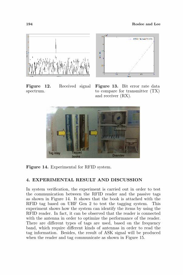
Figure 14. Experimental for RFID system.
4. EXPERIMENTAL RESULT AND DISCUSSION
In system verification, the experiment is carried out in order to testthe communication between the RFID reader and the passive tagsas shown in Figure 14. It shows that the book is attached with theRFID tag based on UHF Gen 2 to test the tagging system. Thisexperiment shows how the system can identify the items by using theRFID reader. In fact, it can be observed that the reader is connectedwith the antenna in order to optimize the performance of the reader.There are different types of tags are used, based on the frequencyband, which require different kinds of antennas in order to read thetag information. Besides, the result of ASK signal will be producedwhen the reader and tag communicate as shown in Figure 15.

Progress In Electromagnetics Research B, Vol. 40, 2012 195
Figure 15. Communication between reader and passive tag result ofthe ASK signal.
Figure 16. Prototype software design for RFID tagging system.
4.1. Prototype Software Design
Moreover, a prototype software is developed in order to interface withImpinj RFID reader through the ethernet connection as shown inFigure 16. This prototype software is able to fast identify the itemsimultaneously based on the EPC number read from the tag. The EPC

196 Roslee and Lee
Figure 17. Prototype software design for RFID tagging databasesystem.
number from each tag will be automatically recorded in the databasecorresponding to the specific items. All information such as an ID,name, and date and so on can be found in the database system asshown in Figure 17.
Moreover, this software can be implemented to check the quantityof the product available in the stock. It also can be observed inthe list of books that a different color is used to classify whether abook is removed or borrowed. This system identical to the currentdeveloped RFID library system can be implemented at the POS systemfor product tracking purpose. Apart from this, by using the LLRPprotocol identified as asymmetric protocol, the Client-PC is able tospeak with the reader where it can initiate the connections. Based onthe Reader Operation Specification of Antenna Inventory Specification(AISpec), it will instructs the reader from the antenna settings andparticulars about the inventory operation, such as an inventory stoptime and type of antenna. In some cases, even though the clientPC has lost connection with the reader, it is still able to obtain thereports back from the reader. Besides, the software also allows the tagselection criteria to be configured and is implemented by using a tagdata pattern, antenna, or a specific Reader Operation Specification.
Meanwhile, another prototype software is developed as shownin Figure 18. The purpose is to make a pairing with the PC inorder for them to communicate through the virtual COM port. Theinterface with the Bluetooth mobile phone is important for transactionpurpose. The transmitted and received data are needed to performthe encryption and decryption process in order to ensure the security.

Progress In Electromagnetics Research B, Vol. 40, 2012 197
Figure 18. Prototype software design for Bluetooth device link withPC.
Figure 19. Prototype software for data encryption and decryptiontoward the security level of transactions.
As a verification result, the data encryption and decryption towardthe security level of transactions has been successfully implemented asshown in Figure 19.
Finally, the whole complete prototype POS software as anintegrated system is developed as shown in Figure 20. This POSsoftware is designed as user friendly, such as auto-summing up theprices of the items purchased by the user, which makes the operatorwork easier. It does not need a traditional scanning method where the

198 Roslee and Lee
Figure 20. Prototype software design for POS integrated system.
customers just send their authorization signal for customer approvalvia Bluetooth and will show the items taken in the trolley to thecustomer. The customer is able to make a fast transaction becausewithout waiting there will be less crowded at the counter. Besides,this integrated system allows controling the inventory system suchas tracking, restoring, or refilling the items found in the stock. Thedevelopment of this integrated POS software shows that the RFIDand Bluetooth technologies are successfully implemented and usefulfor everyone and make sales business grow rapidly.
5. PROJECT CONTRIBUTION
Based on the result and discussion, the design of wireless technologywhich involves radio frequency identification (RFID) and Bluetoothtechnology for tagging and transmission of data is successfullyimplemented. By using the RFID and Bluetooth technologiesimplemented in the POS system, consumers no longer waste time toqueue up at the cashier terminal and can select their preferred itemsand easily purchase through the Bluetooth mobile phone. Besides,consumers are able to search the availability of their preferred itemsfrom the stock database through the Bluetooth mobile phone. Withboth the technologies implemented in POS system, sales business willgrow rapidly.

Progress In Electromagnetics Research B, Vol. 40, 2012 199
6. CONCLUSIONS
In conclusion, in this paper, wireless communication, such as RFIDsystem and Bluetooth system, is investigated for POS systemimprovement. RFID tagging enables items tracking and identifyingeasily compared with barcode system. Meanwhile, Bluetooth systemenables fast transaction to make purchase secure by using the proposedasymmetric algorithm. Finally, the design for such a wirelesscommunication system is useful for future POS system improvement.
ACKNOWLEDGMENT
The research is supported by Plexus Technology. The authors wouldalso like to thank Plexus Technology and Impinj for providing theinformation on the RFID reader and tag to be used on this project.Thanks are also to center of broadband communication to give theessential support throughout the research project.
REFERENCES
1. Finkenzeller, K., RFID Handbook, 4th edition, John Wiley & Sons,Ltd., http://www.rfid-handbook.de, 2003.
2. Golmie, N., R. E. Van Dyck, and A. Soltanian, “Interferenceof Bluetooth and IEEE 802.11: Simulation modeling and per-formance evaluation,” Proceedings of the 4th ACM InternationalWorkshop on Modeling, Analysis and Simulation of Wireless andMobile Systems, 11–18, 2001.
3. Song, M., S. Shetty, and D. Gopalpet, “Coexistence of IEEE802.11b and Bluetooth: An integrated performance analysis,”Mobile Networks and Applications, Vol. 12, No. 5, 450–459, 2007.
4. Impinj, “RFID and semiconductor intellectual property technolo-gies,” http://www.impinj.com, 2011.
5. “How does RFID tag technology works,” ScienceProg.,http://www.scienceprog.com/how-does-rfid-tagtechnology-works,2011.
6. Weier, M., “Wal-Mart gets tough on RFID,” InformationWeek,2008.
7. O’Connor, M., “Wal-Mart, Sam’s club push RFID further along,”RFID Journal, http://www.rfidjournal.com/article/articleview/3666/1/1/, 2007.

200 Roslee and Lee
8. Olenewa, J. and M. Ciampa, Radio Frequency Identification,Wireless Guide to Wireless Communications, 2nd edition,Chapter 11, 401, Thomson Course Technology, 2007.
9. Golmie, N., “Bluetooth dynamic scheduling and interferencemitigation,” Mobile Networks and Applications, Vol. 9, No. 1, 21–31, 2004.
10. Yacine, R., S. Evren, and D. Yves, “Inventory inaccuracy inretail stores due to theft: An analysis of the benefits of RFID,”International Journal of Production Economics, Vol. 118, No. 1,189–198, 2009.
11. Ryu, E.-K. and T. Takagi, “Hybrid approach for privacy-preserving RFID tags,” Computer Standards and Interfaces,Vol. 31, No. 4, 812–815, 2009.
12. Hsu, Y.-C., A.-P. Chen, and C.-H. Wang, “A RFID-enabledtraceability system for the supply chain of live fish,” IEEEInternational Conference on Automation and Logistics, ICAL2008, 81–86, 2008.
13. Wadhwa, M. and M. Song, “Performance of IEEE 802.11b devicesin the presence of adaptive frequency hopping enabled Bluetoothdevices,” Proceedings of the 4th IEEE International Conference onInformation Technology: Research and Education, 74–48, 2006.
14. Mathew, A., N. Chandrababu, K. Elleithy, and S. Rizvi, “IEEE802.11 & Bluetooth interference: Simulation and coexistence,”7th Annual Conference on Communication Networks and ServicesResearch, 217–223, 2009.
15. Vilovic, I. and B. Zovko-Cihlar, “Performance analysis of wirelessnetwork using Bluetooth and IEEE 802.11 devices,” Proceedingsof the 46th International Symposium in Electronics in Marine,235–240, 2004.
Related Documents