Bachelor's thesis (TUAS) Information Technology Information Technology 2015 Sanjib Gurung IMPLEMENTATION OF MPLS VPN

Welcome message from author
This document is posted to help you gain knowledge. Please leave a comment to let me know what you think about it! Share it to your friends and learn new things together.
Transcript
Bachelor's thesis (TUAS)
Information Technology
Information Technology
2015
Sanjib Gurung
IMPLEMENTATION OF MPLS VPN
BACHELOR´S THESIS | ABSTRACT TURKU UNIVERSITY OF APPLIED SCIENCES
Information Technology | Technology
2015| 40
Instructor: Ossi Väänänen
Sanjib Gurung
IMPLEMENTATION OF MPLS VPN
Multiprotocol Label Switching has become a key technology in today’s IP
technology for service providers and corporations that prefer to use remote
connectivity. Enterprises are attracted towards service providers which provide
MPLS VPNs. It has attracted a large number of customers due to the certain
advantages over other VPN technologies like Frame Relay and ATM. Due to
the unique features possessed by MPLS VPN, such as VoIP by CoS, scalable
bandwidth, voice and data on a single platform through various sources, today
MPLS VPN has become the leading technology in IP technology.
The main objective of this thesis was to develop an understanding of the nature
of MPLS VPN technology. The MPLS VPN technology is described briefly, and
a network scenario is illustrated to examine the different communication
protocols.
The practical part was carried out in a GNS3 simulator. For the practical
purpose, 7200 series routers were used. A Wireshark network analyzer was
also used to examine the different protocols used for connectivity.
KEYWORDS:
MPLS, VPN, QoS, ATM, Frame Relay
CONTENTS
LIST OF ABBREVIATIONS (OR) SYMBOLS
1 INTRODUCTION 8
2 MULTIPROTOCOL LABEL SWITCHING 9
2.1 Overview of MPLS 9
2.2 Benefits of MPLS 10
2.3 MPLS Operation 11
2.4 MPLS Architecture 12
2.5 Label Distributions 14
2.6 Control Plane and Forwarding Plane 16
3 MPLS VPN 19
3.1 Overview of VPN 19
3.2 VPN Models 20
3.3 Multiprotocol Label Switching Virtual Private Network (MPLS VPN) 22
3.4 MPLS VPN Schematic overview model 23
3.5 MPLS VPN architecture 24
4 IMPLEMENTATION 27
4.1 Requirements 27
4.2 Topology and Address 28
4.3 Configuration 30
4.4 Test Result 32
5 ANALYSIS 34
6 CONCLUSION 39
REFERENCES 40
3.3.1 Layer 3 MPLS VPNs 22
3.3.2 Layer 2 MPLS VPNs 23
LIST OF FIGURES
Figure 1. MPLS Operation [3] ..................................................................................... 11
Figure 2. MPLS header [4] ......................................................................................... 12
Figure 3. Label Stack [5] ............................................................................................. 13
Figure 4.Control Plane and Forwarding Plane [7] ....................................................... 17
Figure 5. MPLS VPN schematic overview [8] .............................................................. 23
Figure 6. IOS image for 7200 ...................................................................................... 27
Figure 7. IOS image installation .................................................................................. 28
Figure 8. WireShark screenshot for MPLS header ...................................................... 34
Figure 9. WireShark screenshot for LDP hello messages ........................................... 35
Figure 10. WireShark screenshot for BGP keepalive message ................................... 36
Figure 11. WireShark screenshot for LDP keepalive message ................................... 37
LIST OF TABLES
Table 1. Address table ................................................................................................ 29
Table 2. Test Result 1 ................................................................................................. 32
Table 3. Test Result 2 ................................................................................................. 33
Table 4. LIB table ....................................................................................................... 38
Table 5. LFIB table ..................................................................................................... 38
LIST OF ABBREVIATIONS (OR) SYMBOLS
MPLS Multiprotocol Label Switching
VPN Virtual Private Network
ATM Asynchronous Transfer Mode
IETF Internet Engineering Task Force
FEC Forwarding Equivalence Class
QoS Quality of Service
GMPLS Generalized Multiprotocol Label Switching
IPv4 Internet Protocol version 4
IPv6 Internet Protocol version 6
SLA Service Level Agreement
CoS Class of Service
BoS Bottom of Stack
TTL Time to Live
LER Label Edge Router
LSR Label Switch Router
CE Customer Edge Router
PE Provider Edge Router
LSP Label Switch Protocol
P Provider Router
C Customer Router
DoD Downstream on Demand label distribution mode
UD Unsolicited Downstream label distribution mode
LLR Liberal Label Retention Mode
CLR Conservation Label Retention Mode

CR-LDP Constraint-Based Routed LDP
RSPP Resource Reservation Protocol
IGP Interior Gateway Protocol
OSPF Open Shortest Path First
EIGRP Enhanced Interior Gateway Routing Protocol
LDP Label Distribution Protocol
RSVP Resource Reservation Protocol
LIB Label Information Base
LFIB Label Forwarding Information Base
WAN Wide Area Network
ITU International Telecommunication Union
GRE General Routing Encapsulation
IPsec Internet Protocol Security
BGP Border Gateway Protocol
VRF Virtual Routing and Forwarding
RD Routing Distinguisher
RT Route Target
RIP Routing Information Protocol
VoIP Voice over Internet Protocol
OSI Operating Systems Interconnection model
IP Internet Protocol
ACL Access Control List
TE Traffic Engineering
ASN Autonomous System Number
IANA Internet Assigned Numbers Authority
GNS3 Graphical Network Simulator-3

IOS Internetworking Operating System

8
TURKU UNIVERSITY OF APPLIED SCIENCES THESIS | Sanjib Gurung
1 INTRODUCTION
Nowadays many new technologies are developed to make our life easy.
Enterprises and companies use these technologies to make their service easy
and cost efficient. We can access and acquire any services from the internet
distantly from anywhere. Employers provide a flexible work environment to their
employees who could do their work staying at home or anywhere in this world.
Due to better reliability and increased performance, Multiprotocol Label
Switching (MPLS) replacing other WAN technologies. In the past different
technologies like Frame Relay, ATM, T1 or E1 dedicated links were used for
WAN connectivity. To maintain the security issues, layer2 VPNs were used in
enterprise networks that are not scalable. The MPLS VPN provides scalability
and can divide larger enterprises into smaller networks. It became very useful in
IT enterprises that have to provide isolated networks to their departments.
Large enterprises are interested in MPLS VPN since it provides a new option
for WAN connectivity.
The main purpose of thesis is to discuss the implementation of MPLS VPN
technology. This thesis includes mainly the configuration needed for the
establishment of MPLS VPN and explains how to implement a MPLS VPN over
an IPv4 network. The thesis also explains the benefits of MPLS VPN over
traditional IP routing and examines MPLS VPN networks, protocols used for
communication and illustrate a network scenario.
The structure of thesis is divided into six chapters. Chapter 1 is an introduction
to the thesis topic and explains the motivation and goal of the thesis topic.
Chapter 2 introduces MPLS technology, MPLS architecture and MPLS
operation. It also explains the qualities of MPLS that enable it to grow rapidly in
a short span of time. Chapter 3 explains the model and architecture of MPLS
VPN. Chapter 4 deals with the implementation of MPLS VPN. It includes that
practical part that presents its configuration and test result. Similarly, Chapter 5
describes the analysis of different protocols used for the connectivity. Chapter 6
is the conclusion of the thesis.
9
TURKU UNIVERSITY OF APPLIED SCIENCES THESIS | Sanjib Gurung
2 MULTIPROTOCOL LABEL SWITCHING
2.1 Overview of MPLS
Multiprotocol Label Switching (MPLS) is an IP technology developed by IETF
to overcome the drawbacks of traditional IP routing. MPLS is a technique used
by service providers to provide better and single network infrastructure for real-
time traffic such as voice and video. In the past, Frame Relay and ATM were
used to transfer data in enterprise. MPLS operates in between the data link
layer and the network layer, so it is called layer 2.5 protocols. MPLS is called
multiprotocol because it supports many network layer protocols. MPLS works
with Internet Protocol (IP), Frame-Relay and Asynchronous Transport Mode
(ATM) network protocols to create a Label Switch Path (LSP) [1]. It provides
scalability to VPNs.
Each router in a traditional IP technology makes their forwarding decision based
on the study of packet’s header and the result of the routing algorithm running
in the network layer. Whenever the packets arrive at the router, it has to think
where to send the packet. However, in MPLS every packet is assigned to
forwarding equivalence class (FEC) as a label that is used to make the
forwarding decision without IP lookups in every node. Every router has a table
that indicates how to handle FEC type of packets. Once the packets enter the
network, subsequent routers use this label as an index to forward the packet
with the help of table present in every router [2].

10
TURKU UNIVERSITY OF APPLIED SCIENCES THESIS | Sanjib Gurung
2.2 Benefits of MPLS
In a very short time, MPLS has become popular and successful in IP
technology. MPLS enables enterprise and service providers to create a next
generation intelligent network that offers value-added services over a single
infrastructure.
Multi-service Networks: The ability to implement multi-service networks is one
of the main reasons behind the popularity of MPLS. It helps the network to
carry all kinds of traffic (e.g., IP traffic, Voice over IP, Layer2 traffic, etc.). MPLS
integrates different technologies, such as Layer2 VPNs, Layer3 VPNs, Traffic
Engineering, QoS, GMPLS, and IPv6 which enables to develop scalable and
secure networks that guarantee Service Level Agreement (SLA). MPLS can
combine ATM, Frame Relay, Voice, and IP networks into single network
infrastructure [1]. Therefore, it has a cost advantage for the customers.
MPLS Virtual Private Network (MPLS VPN): - MPLS VPN is one of the popular,
widespread implementation of MPLS. It provides private and secure networks
called virtual private networks (VPN) over the same network topology to many
customers. Large enterprises and service providers are interested in MPLS
VPN due to its ability to divide network to smaller networks and scalability
feature.
Scalability: In the past, most of the networks used to have a core ATM switches
surrounded by routers that were totally meshed and had many adjacent
networks. The MPLS network helped to fix this kind of problem. The core
devices are not involved in any relationship with the other networks, and their
task is only to switch packets. The virtual tunnels are built to connect with the
core parts of the network that shorten the amount of virtual path.
Traffic Engineering: Another significant reason for deploying an MPLS network
is the implementation of traffic engineering. Traffic engineering is the ability to
control the traffic that helps to use the network infrastructure optimally by
spreading the traffic more evenly over the all available links. The
11
TURKU UNIVERSITY OF APPLIED SCIENCES THESIS | Sanjib Gurung
implementation of traffic engineering in an MPLS network helps to deliver the
traffic in a path that is different from the least-cost path.
2.3 MPLS Operation
Multiprotocol Label Switching is a protocol that integrates Layer 2 information
regarding network links (For example, bandwidth, latency, utilization) into layer
3 (IP) within the network which helps to improve and simplify the exchange of IP
packets.
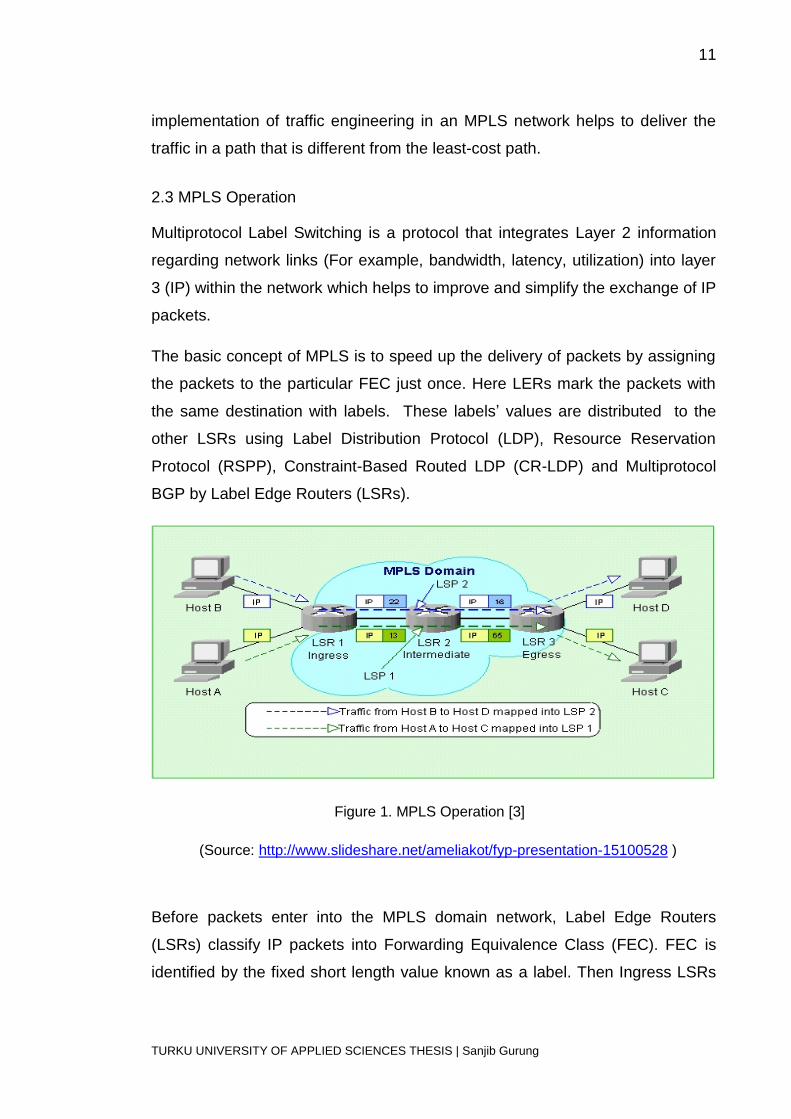
The basic concept of MPLS is to speed up the delivery of packets by assigning
the packets to the particular FEC just once. Here LERs mark the packets with
the same destination with labels. These labels’ values are distributed to the
other LSRs using Label Distribution Protocol (LDP), Resource Reservation
Protocol (RSPP), Constraint-Based Routed LDP (CR-LDP) and Multiprotocol
BGP by Label Edge Routers (LSRs).
Figure 1. MPLS Operation [3]
(Source: http://www.slideshare.net/ameliakot/fyp-presentation-15100528 )
Before packets enter into the MPLS domain network, Label Edge Routers
(LSRs) classify IP packets into Forwarding Equivalence Class (FEC). FEC is
identified by the fixed short length value known as a label. Then Ingress LSRs
12
TURKU UNIVERSITY OF APPLIED SCIENCES THESIS | Sanjib Gurung
assign MPLS headers to the IP packets. After the MPLS is assigned, the
packets are routed through the predetermined Label Switch Path (LSP) by
intermediate LSR. Subsequent routers use this label to forward the packets.
Therefore, packet classification is not necessary for subsequent routers. The
FEC table present in the routers helps to identify the incoming packet label.
After the packets label is identified, it is replaced with the outgoing label and
transferred to the next LSR. Due to the fixed length of the label, the forwarding
operation is much faster than IP forwarding that requires the longest prefix
match of destination IP address. When the packet reaches the destination
router, i.e., Egress LSR, the label is removed and forwarded as an IP packet to
the destination address.
2.4 MPLS Architecture
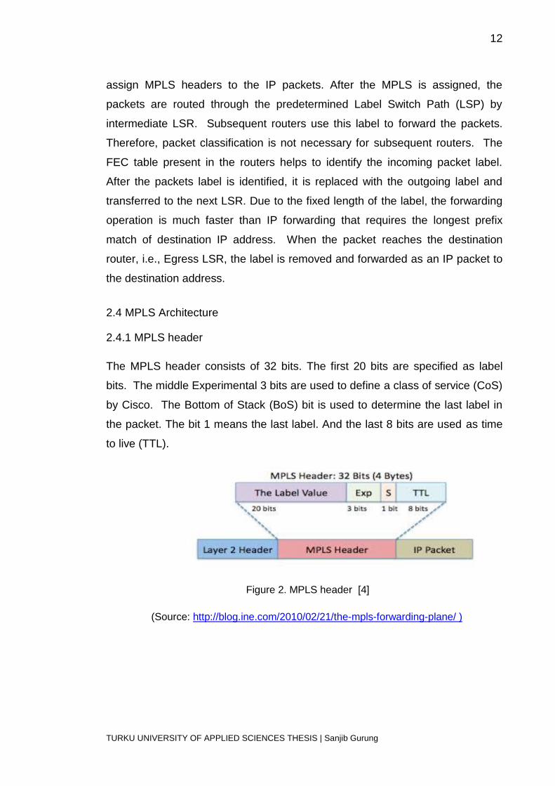
2.4.1 MPLS header
The MPLS header consists of 32 bits. The first 20 bits are specified as label
bits. The middle Experimental 3 bits are used to define a class of service (CoS)
by Cisco. The Bottom of Stack (BoS) bit is used to determine the last label in
the packet. The bit 1 means the last label. And the last 8 bits are used as time
to live (TTL).
Figure 2. MPLS header [4]
(Source: http://blog.ine.com/2010/02/21/the-mpls-forwarding-plane/ )
13
TURKU UNIVERSITY OF APPLIED SCIENCES THESIS | Sanjib Gurung
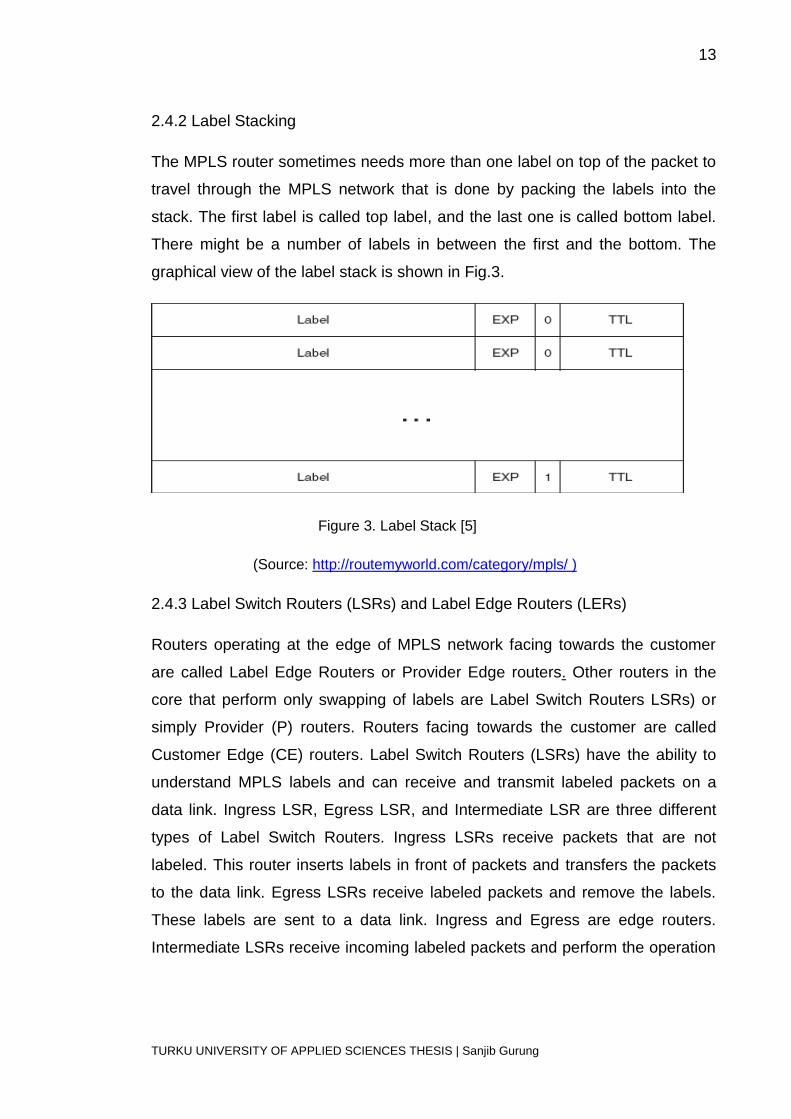
2.4.2 Label Stacking
The MPLS router sometimes needs more than one label on top of the packet to
travel through the MPLS network that is done by packing the labels into the
stack. The first label is called top label, and the last one is called bottom label.
There might be a number of labels in between the first and the bottom. The
graphical view of the label stack is shown in Fig.3.
Figure 3. Label Stack [5]
(Source: http://routemyworld.com/category/mpls/ )
2.4.3 Label Switch Routers (LSRs) and Label Edge Routers (LERs)
Routers operating at the edge of MPLS network facing towards the customer
are called Label Edge Routers or Provider Edge routers. Other routers in the
core that perform only swapping of labels are Label Switch Routers LSRs) or
simply Provider (P) routers. Routers facing towards the customer are called
Customer Edge (CE) routers. Label Switch Routers (LSRs) have the ability to
understand MPLS labels and can receive and transmit labeled packets on a
data link. Ingress LSR, Egress LSR, and Intermediate LSR are three different
types of Label Switch Routers. Ingress LSRs receive packets that are not
labeled. This router inserts labels in front of packets and transfers the packets
to the data link. Egress LSRs receive labeled packets and remove the labels.
These labels are sent to a data link. Ingress and Egress are edge routers.
Intermediate LSRs receive incoming labeled packets and perform the operation
14
TURKU UNIVERSITY OF APPLIED SCIENCES THESIS | Sanjib Gurung
on it. They switch the packet and send it to the correct data link.2.4.4 Label
Switch Path (LSP)
The path taken by packets through the MPLS network is called Label Switch
Path (LSP). It is the path where the packet passes through the Ingress LSR
and to intermediate LSR and finally to the egress LSR. LSP is unidirectional
and starts from Ingress LSR to Egress LSR.
2.4.5 Forwarding Equivalence Class (FEC)
All the packets having the same FEC have the same labels. However, packets
with same labels may not belong to the same FEC. Ingress LSRs determine
which packets belong to which FEC.
2.5 Label Distributions
When the packet enters the MPLS topology, Ingress LSR receives the packet
and imposes the MPLS label to the packet and forwards to the next hop via the
Label Switch Path. When the packet reaches the next LSR, i.e., the
intermediate LSR, it swaps the incoming label with the outgoing label and
transmits the packet. When the Egress LSR receives the packet, it strips off the
packet label and forwards it to the destination router.
All the LSRs present in the MPLS network have Interior Gateway Protocol (IGB)
(e.g., EIGRP, RIP, OSPF, etc.) running throughout the network [6]. To
accomplish the label distribution task, adjacent LSRs must agree on the label
that is used for each IGP prefix. Each LSR should be able to identify the
swapping of incoming and outgoing labels. Since the labels are local to
adjacent routers that do not have global meaning across the network, we need
a mechanism to instruct the routers which label should be used while
forwarding the packets. Therefore, two adjacent routers need some sort of
communication between them to agree on which label to use for a particular
prefix. Otherwise, the routers do not get any idea about the swapping packets.
For this purpose or to complete label Distribution, the Label Distribution
15
TURKU UNIVERSITY OF APPLIED SCIENCES THESIS | Sanjib Gurung
Protocol is needed. Label Distribution is carried out in two different following
ways:
Piggyback the labels on an existing IP routing protocol.
Have a separate protocol distribute labels.
2.5.1 Piggyback the labels on an existing IP routing protocol
In this method, LSRs do not need new protocol but they need to extend the
existing routing protocol to carry labels. There is a great advantage of this
method because the Routing and Label Distribution are always in sync which
means both labels and prefix should be present. The implementation is very
easy for the distance vector routing protocols, e.g., EIGRP, which originate the
prefix from the routing table. Then the router binds the label with that prefix.
Link state routing protocols (e.g., OSPF) work differently from the distance
vector protocols. In link-state routing protocols, each router originates link state
updates and forwards the original updates by all the routers in the same area.
Nevertheless, the problem with MPLS is that every router needs to distribute
labels for each IGP prefix even to the router that does not originate a prefix. A
separate protocol is required for label distribution in Link state routing protocols.
Border Gateway Protocol (BGP) is the one routing protocol in the MPLS VPN
which can carry prefixes and distribute labels at the same time.
2.5.2 Separate Protocol for Label Distribution
This Label Distribution method needs a separate protocol to distribute the labels
and lets the routing protocol to distribute the prefixes. The advantage of this
method is routing protocol independent, and the disadvantage is that a new
protocol is needed in each LSR. There are several varieties of protocols that
distribute labels including:
Tag Distribution Protocol (TDP)
Label Distribution Protocol (LDP)
Resource Distribution Protocol (RSVP).
16
TURKU UNIVERSITY OF APPLIED SCIENCES THESIS | Sanjib Gurung
TDP was the first protocol developed and implemented by Cisco for label
distribution. LDP was later designed and developed by IETF. TDP and LDP
operate in a similar way, but LDP has more functionality than TDP. Due to the
easy availability of LDP, TDP was replaced by LDP in a very short time frame.
RSVP is only used for MPLS traffic engineering.
Label Distribution Protocol (LDP): LSRs in an MPLS network create a local
binding that binds a label to the IPv4 prefix. Then this binding is distributed to
LDP neighbors by LSRs. When the neighboring routers receive this binding, it
becomes remote binding. The neighboring routers store these remote and local
bindings in the special table called Label Information Base (LIB). Out of many
remote bindings for one prefix selected via the routing table, this remote binding
serve as outgoing labels. Therefore, when LSRs receive packets labeled, they
are capable of swapping the incoming labels with outgoing labels. LSRs need to
select only one to use to determine the outgoing label for that IP prefix. The
next hop of the IP prefixes is determined from the routing table. LSRs select the
remote binding received from the next LSR which is the next hop in the routing
table for that prefix. LSRs use this information to set up its label forwarding
information base (LFIB) where labels from local binding serve as incoming
labels and labels from the one remote binding.
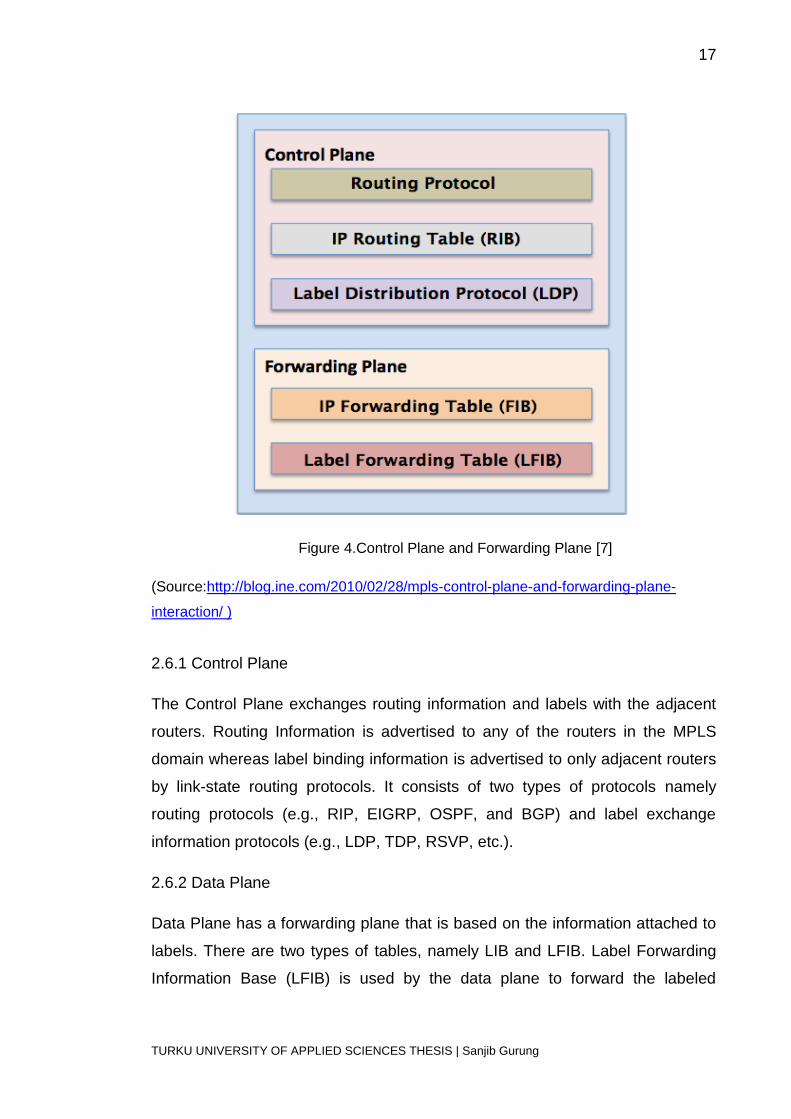
2.6 Control Plane and Forwarding Plane
Control Plane and Forwarding Plane are the part of router architecture. Control
Plane collects the information that is used to forward the incoming packets.
While Forwarding Plane decides how to switch the incoming packets after being
received at inbound interface. You need to write an introductory sentence here.
17
TURKU UNIVERSITY OF APPLIED SCIENCES THESIS | Sanjib Gurung
Figure 4.Control Plane and Forwarding Plane [7]
(Source:http://blog.ine.com/2010/02/28/mpls-control-plane-and-forwarding-plane-
interaction/ )
2.6.1 Control Plane
The Control Plane exchanges routing information and labels with the adjacent
routers. Routing Information is advertised to any of the routers in the MPLS
domain whereas label binding information is advertised to only adjacent routers
by link-state routing protocols. It consists of two types of protocols namely
routing protocols (e.g., RIP, EIGRP, OSPF, and BGP) and label exchange
information protocols (e.g., LDP, TDP, RSVP, etc.).
2.6.2 Data Plane
Data Plane has a forwarding plane that is based on the information attached to
labels. There are two types of tables, namely LIB and LFIB. Label Forwarding
Information Base (LFIB) is used by the data plane to forward the labeled
18
TURKU UNIVERSITY OF APPLIED SCIENCES THESIS | Sanjib Gurung
packets. The Local Information Base (LIB) table contains all the local labels and
the mapping of the labels which is received from the adjacent routers. The
information in LFIB and label value is used by the MPLS-enabled routers to
make forwarding decisions.
19
TURKU UNIVERSITY OF APPLIED SCIENCES THESIS | Sanjib Gurung
3 MPLS VPN
3.1 Overview of VPN
A Virtual Private Network (VPN) is a technology that helps to create a private
network across a public network (e.g., the Internet). It is virtual since there is no
real physical connection between the sites. A VPN enables network-enabled
devices to transmit data across the shared or public network infrastructure
securely and privately. A VPN is created by using dedicated connections, like
virtual tunneling protocols or traffic encryption. A tunnel is formed in this
technology that is used to transfer packets through the public networks. In a
VPN, there is a virtual point to point connection. A VPN connection provides a
service similar to a WAN. Service providers or organizations use a VPN to
interconnect all the sites that belong to the same corporation. For example, an
organization uses a VPN which provides virtual WAN infrastructure to
interconnect all or the portions of the branches or departments of their network.
In the past, leased lines, frame relay, and lower layer transport services were
used to exchange information. But at the present, service providers use VPNs
to achieve their networking requirements that provide them with enterprise-
scale connectivity. It is more secure and private to use VPNs because only the
authorized users can use the network. VPNs can be created on the service
provider’s IP, Frame Relay or ATM infrastructure. They can be deployed on the
shared infrastructure having similar policies to that of private networks. In
private networks, all the customer sites’ VPNs should be interconnected and
completely different from other corporate VPNs and that is the minimum
connectivity requirement. However, at the IP layer, VPN models or VPNs need
to connect with different VPNs and with the internet as well.
Intranet and Extranet are two types of VPN usages. The local network in the
corporation where the VPN is only used inside the company and is not visible to
outside the company is called intranet. This type of network is safe from the
malicious attack from the outside the corporation; whereas the remote network

20
TURKU UNIVERSITY OF APPLIED SCIENCES THESIS | Sanjib Gurung
of the company which uses IP network connectivity to allow the remote users to
use the VPN is called extranet. Extranet acts as intranet in the internet because
firewalls protects the server and monitor the access between intranet and
internet. Only authenticated users can connect to this network.
There are plenty of benefits of VPN. Users in remote sites can securely connect
to the company network from anywhere. Encryption and authorization protocols
make VPN more secure. It is more economical in that it decreases connectivity
costs and increases the remote connection bandwidth. In addition, it is easy for
an organization to increase the number of users since a VPN uses the Internet
infrastructure within ISPs and carriers.
3.2 VPN Models
There are two types of VPN models:
The Overlay VPN model and
The Peer-to-Peer VPN model
In the Overlay VPN model, service providers provide service in a point to point
links or virtual circuits whereas in the Peer-to-Peer model, the service providers’
routers participate in customer routing.
3.2.1 Overlay VPN model
In Overlay VPN model service provider provides virtual leased lines to the
customer. Service Provider is responsible for creating layer 2 virtual circuits
between the customer sites using Frame Relay, ATM or X.25. Whereas, in layer
3 VPN, either Generic Routing Encapsulation (GRE) or IP Security (IPSEC) is
used to create tunnels for the implementation of VPN.
Layer 2 VPN
- Frame Relay
- ATM
- X.25
Layer 3 VPN
- GRE
21
TURKU UNIVERSITY OF APPLIED SCIENCES THESIS | Sanjib Gurung
- IPsec
3.2.2 Peer to Peer VPN model
In Peer to Peer VPN model, both service provider and customer use same
network protocol. This model uses very simple routing scheme for the
customer.
ACLs
Split Routing
MPLS VPN
Frame Relay: Frame Relay is a cost effective service designed for packet
switching telecommunication. It is used for data exchange for discontinuous
traffic between LANs and between end points of WANs. It puts data on a
variable unit called frame and leaves necessary error correction to the end
points which makes the data transmission faster. It is cheaper than a leased
line.
ATM: Asynchronous Transfer Mode (ATM) is a cell-switching and multiplexing
technology that encodes data into a small-sized unit called cells. It was built for
a network to carry data traffic and real-time traffic. Since ATM uses the
connection-oriented model, a virtual circuit should be established across ATM
networks before data transfer.
X.25: X.25 is a protocol used in packet switching across wide area networks
(WAN). It was developed by International Telecommunication Union (ITU) many
years back to carry voice over dialup networks (telephone lines). X.25 protocols
operate at physical, data link, and network layers. Today X.25 is used in
automatic teller machine (ATM) and credit cards verification networks.
GRE: Generic Routing Encapsulation (GRE) is one of the tunneling
mechanisms that encapsulate layer 3 packets over IP networks. It is used
particularly to transmit multicast traffic over IPsec. GRE packets are IP
protocols that are not encrypted.
22
TURKU UNIVERSITY OF APPLIED SCIENCES THESIS | Sanjib Gurung
IPsec: Internet Protocol Security (IPsec) is a protocol suite that uses
cryptographic keys to secure Internet Protocol (IP) communications. IPsec
operates in the Internet layer that provides an end-to-end security scheme. We
can configure IPsec by using Windows firewall with advanced security snap-in
feature in the Windows 7 and Windows 8 server.
ACLs: Access Control Lists (ACLs) are sets of rules used to filter traffic which
are applied in routers. They are used by network administrators to secure the
networks by allowing or denying the hosts or addresses. ACLs are used to
control the routing updates or packets from going out and coming in of the
networks. They can also be configured on the basis of TCP port being used.
There are two types of ACLs:
Standard access list
Extended access list
3.3 Multiprotocol Label Switching Virtual Private Network (MPLS VPN)
A Multiprotocol Label Switching Virtual Private Network (MPLS VPN) is one of
the most renown and world-wide implementation of MPLS technology. It is a
VPN built on MPLS network by the service providers to deliver connection
between enterprises and its branches. Today most of the service providers are
using MPLS VPN as a replacement to Frame Relay and ATM services. Within a
short time span, the popularity of MPLS VPN has grown very high because it is
less expensive, flexible, simple and easy to manage for enterprises and service
providers. There are two types of MPLS VPN:
Layer 3 MPLS VPNs
Layer 2 MPLS VPNs
3.3.1 Layer 3 MPLS VPNs
Layer 3 MPLS VPNs normally refer to MPLS VPN. It is a peer-to-peer model
which uses the Border Gateway Protocol (BGP) for the distribution of VPN-
related information. When a Layer 3 MPLS VPN service is used, the service
providers’ routers form the core of the WAN network. It is highly scalable which
23
TURKU UNIVERSITY OF APPLIED SCIENCES THESIS | Sanjib Gurung
enables enterprises or customers to outsource routing information to service
providers. This helps to reduce costs by reducing the operational complexity of
the enterprises or the customers.
3.3.2 Layer 2 MPLS VPNs
Layer 2 MPLS VPNs operate at layer 2 of the OSI model. Internet providers
who have already layer 2 networks, like ATM or Frame Relay prefer Layer 2
MPLS VPNs. It is a kind of virtual circuit service normally used in the Metro
Ethernet field. BGP-based and LDP-based are two types of Layer 2 MPLS
VPNs. In the forwarding plane, both approaches are similar regarding the
encapsulation of layer 2 frames for the transportation through the MPLS
network. Yet, these approaches differ in the control plane. A point-to-point
Layer 2 connection over an MPLS domain is offered by a pseudowire. A
pseudowire is a term used in industry for the transportation of frames across an
MPLS domain which uses MPLS to encapsulate packets and LDP as a
mechanism for signaling.
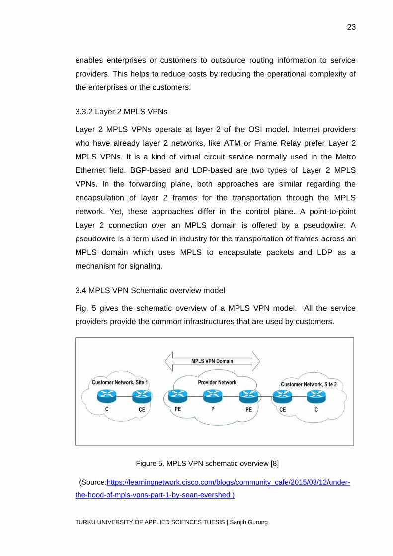
3.4 MPLS VPN Schematic overview model
Fig. 5 gives the schematic overview of a MPLS VPN model. All the service
providers provide the common infrastructures that are used by customers.
Figure 5. MPLS VPN schematic overview [8]
(Source:https://learningnetwork.cisco.com/blogs/community_cafe/2015/03/12/under-
the-hood-of-mpls-vpns-part-1-by-sean-evershed )
24
TURKU UNIVERSITY OF APPLIED SCIENCES THESIS | Sanjib Gurung
There are two types of routers in the service providers’ network, i.e., Provider
Edge (PE) and Provide (P) routers. The Provider Edge router is directly
connected to the Customer Edge (CE) router of the customer networks. Both
Provider Edge (PE) and Provider (P) routers should run MPLS so that they can
distribute labels to each other and forward labeled packets to subsequent
routers.
The customer edge (CE) router is directly connected to the PE router at layer 3
while the customer (C) router is not directly connected to the PE router. The CE
router does not need to run MPLS because the PE and CE routers interact at
layer 3 using a routing protocol or static routing. The CE router can only peer
with one PE router and cannot have peering with another CE router on another
site across the provider network. The peer-to-peer model is the outcome of
peering between PE and CE routers at layer 3.
3.5 MPLS VPN architecture
There are three fundamental building blocks on PE routers. They are as follows:
Virtual Routing Forwarding (VRF)
Route Distinguisher (RD)
Route Targets (RT)
3.5.1 Virtual Routing Forwarding (VRF)
Virtual Routing Forwarding (VRF) is a technology used in VPN routing and
forwarding instance. It is the combination of VPN routing table, the associated
IP routing protocols, and the VRF Cisco Express Forwarding table. It allows
these multiple instances of the routing table to exist in the same router and
perform simultaneously. In a PE router, there must be separate and private
routing for each VPN which is called VRF routing table. The interface of the PE
routers connected to CE routers can belong to only one VRF. All the packets
received by the VRF interfaces are considered to belong to that VRF due to the
presence of separate routing table for each VPN. It is because there is a
separate CEF table for each VPN to forward the packets to the PE router called
VRF CEF table.

25
TURKU UNIVERSITY OF APPLIED SCIENCES THESIS | Sanjib Gurung
We can create a VRF table on the PE router with the ip vrf command. We can
also assign interfaces on PE and CE routers with the help of the ip vrf
forwarding command. The particular interface is assigned to only one VRF, but
several interfaces can be assigned to the same VRF. Then the VRF routing
table and CEF are automatically created by the PE router. The VRF table is
similar to a regular routing table that is only used for VPN sites and is totally
separated from all other routing tables.
3.5.2 Route Distinguisher (RD)
Multiprotocol BGP (MP-BGP) is used by the VPN to propagate its prefixes over
the MPLS VPN networks. The IPv4 prefixes carried by BGP across the service
providers’ network should be unique. If there is overlapping in the customers’ IP
addressing, there will be a problem in routing. To overcome this problem, the
route distinguisher concept was developed to make IPv4 prefixes unique. The
idea is that a unique identifier is received from each customer with each prefix
to differentiate the same prefix from other customers. The IPv4 prefix and RD
combine to give the vpnv4 prefix. VPNv4 prefixes are carried by MP-BGP
between the PE routers.
The route distinguisher (RD) is a 64-bit field that makes the VRF prefixes
unique. This 64-bit value can be in two formats: ASN:nn or IP-address:nn where
nn is a number, and ASN stands for autonomous system number [1]. ASN:nn is
the popular format used by most service providers. Internet Assigned Numbers
Authority (IANA) assigns ASN to the service providers, and nn is the number
uniquely assigned to VRF by the service provider. RD combines with IPv4
prefixes to form VPNv4 prefix that is 96 bit long, and the subnet mask is 32 bits.
If the IP address is 30:30:30:0/24 and RD is 1:1 then the VPNv4 prefix will
become 1:1 30:30:30:0/24.
3.5.3 Route Targets (RTs)
A Route Target is the feature of MPLS VPN which controls the communication
between different VPN sites. The Route Target (RT) was introduced to
overcome the drawbacks of the route distinguisher (RD) since the RD can only
26
TURKU UNIVERSITY OF APPLIED SCIENCES THESIS | Sanjib Gurung
communicate with one VPN; whereas RT can communicate with complex VPN
topologies.
Route Target (RT) is the BGP extended member which indicates the route that
should be imported from MPLS BGP into VRF. The RT attached with the vpnv4
route is called exported route and configured under the ip vrf command
separately for each virtual routing table on the PE router. The vpnv4 route
received from MPLS BGP is examined for a matching extended community
which is the route target. This procedure is called importing an RT. If the result
matches, the prefix is inserted into the VRF routing table as the vpnv4 route.
Otherwise, the prefix is rejected.
When a PE router broadcasts a vpnv4 router to the other PE routers, these
routers need to select the appropriate route to import into their virtual routing
table. Here the selection of route depends on RTs. There is a number of RTs on
each virtual routing table of PE routers which identify the set of VPNs that the
virtual routing table is accepting routes from.
27
TURKU UNIVERSITY OF APPLIED SCIENCES THESIS | Sanjib Gurung
4 IMPLEMENTATION
4.1 Requirements
For the implementation of MPLS VPN, routers must require minimum hardware
and software requirements to support the MPLS VPNs. These prerequisites are
as follows:
Router that support MPLS
Cisco IOS. Software release 12.2(6h) which include the VPN features [9]
and
64 MB of flash to support IOS and at least 192 DRAM.
We can use any routers from 7200 or higher for P routers and any routers from
2691 series or 3640 or higher series can be used for PE functionality. For CE
routers, we can use any router that can exchange routing information with its
PE routers.
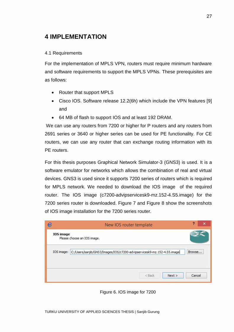
For this thesis purposes Graphical Network Simulator-3 (GNS3) is used. It is a
software emulator for networks which allows the combination of real and virtual
devices. GNS3 is used since it supports 7200 series of routers which is required
for MPLS network. We needed to download the IOS image of the required
router. The IOS image (c7200-advipservicesk9-mz.152-4.S5.image) for the
7200 series router is downloaded. Figure 7 and Figure 8 show the screenshots
of IOS image installation for the 7200 series router.
Figure 6. IOS image for 7200
28
TURKU UNIVERSITY OF APPLIED SCIENCES THESIS | Sanjib Gurung
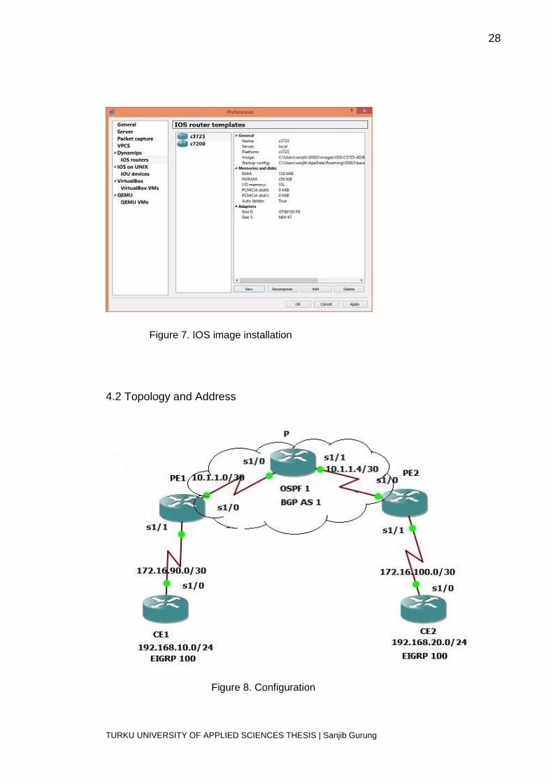
Figure 7. IOS image installation
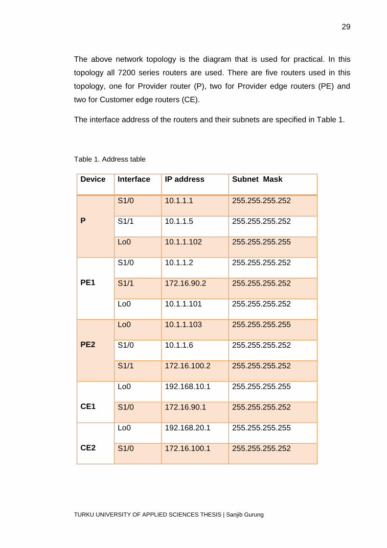
4.2 Topology and Address
Figure 8. Configuration
29
TURKU UNIVERSITY OF APPLIED SCIENCES THESIS | Sanjib Gurung
The above network topology is the diagram that is used for practical. In this
topology all 7200 series routers are used. There are five routers used in this
topology, one for Provider router (P), two for Provider edge routers (PE) and
two for Customer edge routers (CE).
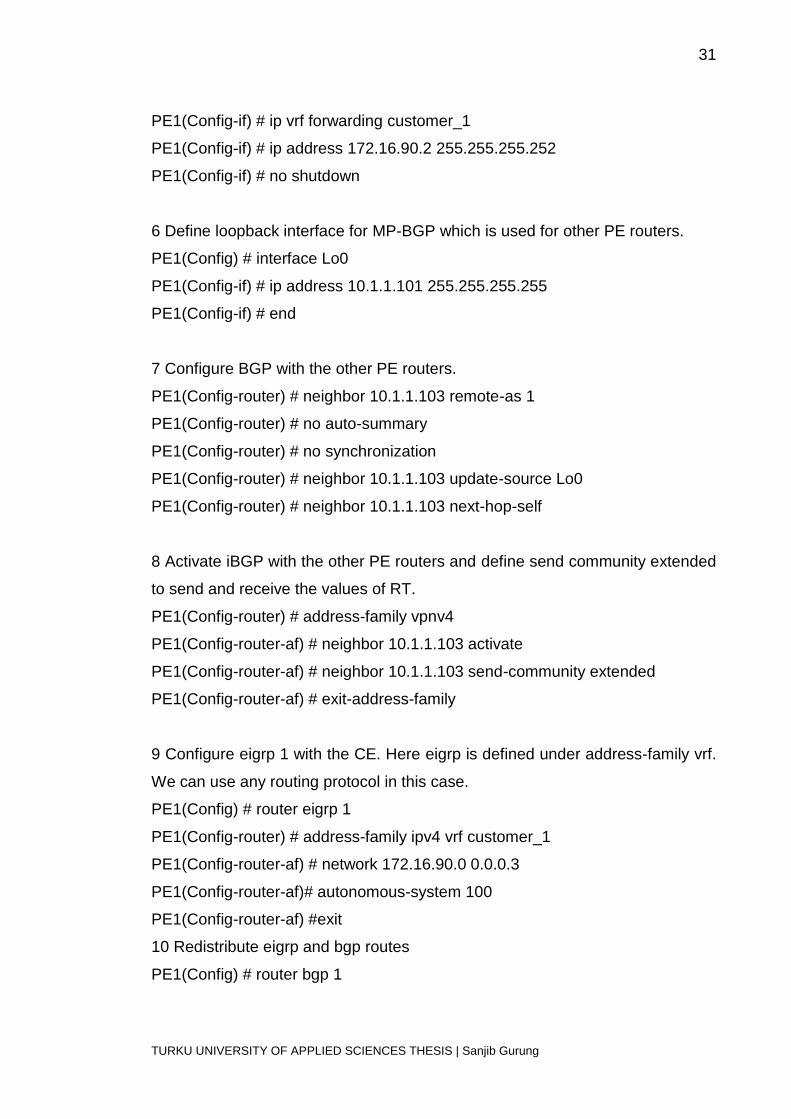
The interface address of the routers and their subnets are specified in Table 1.
Table 1. Address table
Device Interface IP address Subnet Mask
P
S1/0 10.1.1.1 255.255.255.252
S1/1 10.1.1.5 255.255.255.252
Lo0 10.1.1.102 255.255.255.255
PE1
S1/0 10.1.1.2 255.255.255.252
S1/1 172.16.90.2 255.255.255.252
Lo0 10.1.1.101 255.255.255.252
PE2
Lo0 10.1.1.103 255.255.255.255
S1/0 10.1.1.6 255.255.255.252
S1/1 172.16.100.2 255.255.255.252
CE1
Lo0 192.168.10.1 255.255.255.255
S1/0 172.16.90.1 255.255.255.252
CE2
Lo0 192.168.20.1 255.255.255.255
S1/0 172.16.100.1 255.255.255.252

30
TURKU UNIVERSITY OF APPLIED SCIENCES THESIS | Sanjib Gurung
4.3 Configuration
Customer routers can be configured with any types of routing IP protocols such
as RIP, EIGRP or EIGRP, etc. but the PE and P routers that take part in label
switching should be configured with MPLS and other BGP routing protocols. All
the IP address and values were used in reference to the above figure. The
configuration commands are explained as below.
1 Configure routing protocol for the MPLS network. Any routing protocol can
be used for the MPLS network. Here OSPF is used. When OSPF is configured
between P and PE routers, there will be exchange of hello messages [10].
PE1(Config) # router ospf 1
PE1(Config-router) # network 10.1.1.0 0.0.0.3 area 0
PE1(Config-router) # network 10.1.1.101 0.0.0.0 area 0
2 Define the PE router with MPLS labels protocol and Router-id interface.
PE1(Config) # mpls ip
PE1(Config) # mpls label protocol ldp
PE1(Config) # mpls ldp router-id Lo0
3 Configuration of the interface used in LDP.
PE1(Config) # interface s1/0
PE1(Config-if) #ip address 10.1.1.2 255.255.255.252
PE1(Config-if) # mpls ip
PE1(Config-if) # mpls label protocol ldp
PE1(Config-if) #no shutdown
4 Configure vrf. Specify route distinguisher and route-target value.
PE1(Config) # ip vrf customer_1
PE1(Config-vrf) # rd 1:100
PE1(Config-vrf) # route-target both 1:100
5 Specify the Customer Interfaces with the VRF and assign IP address .
PE1(Config) # interface s1/0
31
TURKU UNIVERSITY OF APPLIED SCIENCES THESIS | Sanjib Gurung
PE1(Config-if) # ip vrf forwarding customer_1
PE1(Config-if) # ip address 172.16.90.2 255.255.255.252
PE1(Config-if) # no shutdown
6 Define loopback interface for MP-BGP which is used for other PE routers.
PE1(Config) # interface Lo0
PE1(Config-if) # ip address 10.1.1.101 255.255.255.255
PE1(Config-if) # end
7 Configure BGP with the other PE routers.
PE1(Config-router) # neighbor 10.1.1.103 remote-as 1
PE1(Config-router) # no auto-summary
PE1(Config-router) # no synchronization
PE1(Config-router) # neighbor 10.1.1.103 update-source Lo0
PE1(Config-router) # neighbor 10.1.1.103 next-hop-self
8 Activate iBGP with the other PE routers and define send community extended
to send and receive the values of RT.
PE1(Config-router) # address-family vpnv4
PE1(Config-router-af) # neighbor 10.1.1.103 activate
PE1(Config-router-af) # neighbor 10.1.1.103 send-community extended
PE1(Config-router-af) # exit-address-family
9 Configure eigrp 1 with the CE. Here eigrp is defined under address-family vrf.
We can use any routing protocol in this case.
PE1(Config) # router eigrp 1
PE1(Config-router) # address-family ipv4 vrf customer_1
PE1(Config-router-af) # network 172.16.90.0 0.0.0.3
PE1(Config-router-af)# autonomous-system 100
PE1(Config-router-af) #exit
10 Redistribute eigrp and bgp routes
PE1(Config) # router bgp 1

32
TURKU UNIVERSITY OF APPLIED SCIENCES THESIS | Sanjib Gurung
PE1(Config-router)# redistribute eigrp 100 ( which is configured in CE1)
PE1(Config) # router eigrp 1
PE1(Config-router) # redistribute bgp 1 metric 1500 4000 20 10 1500
4.4 Test Result
Test Result 1 shows the MPLS VPNs configured in the PE1 and PE2 routers.
Table 2. Test Result 1
33
TURKU UNIVERSITY OF APPLIED SCIENCES THESIS | Sanjib Gurung
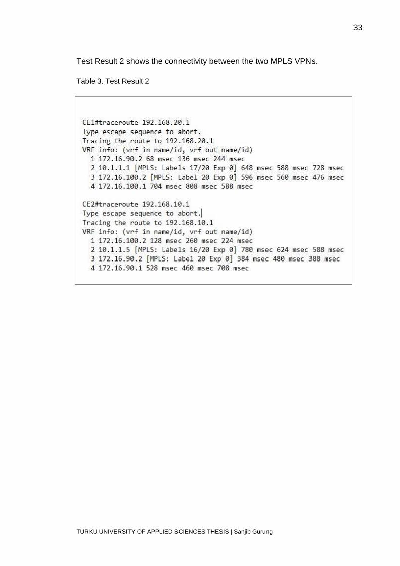
Test Result 2 shows the connectivity between the two MPLS VPNs.
Table 3. Test Result 2
34
TURKU UNIVERSITY OF APPLIED SCIENCES THESIS | Sanjib Gurung
5 ANALYSIS
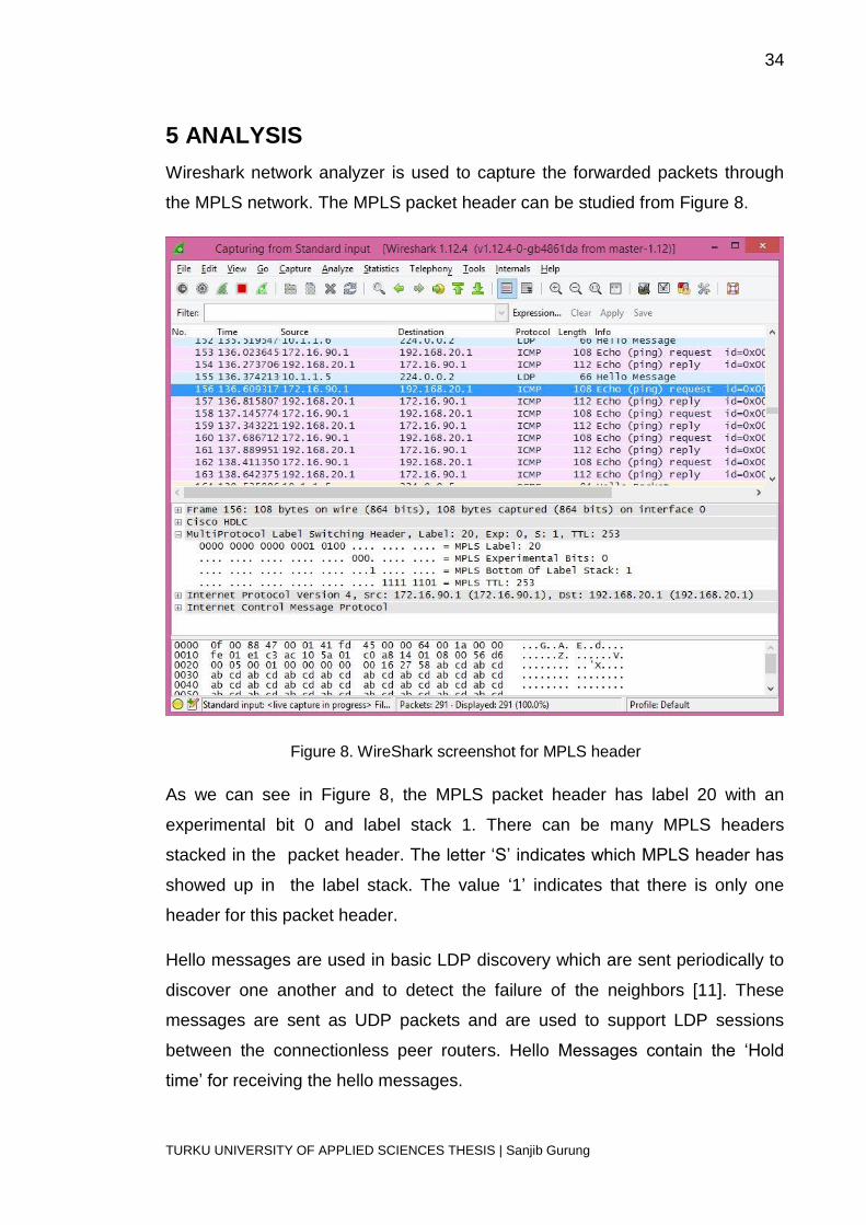
Wireshark network analyzer is used to capture the forwarded packets through
the MPLS network. The MPLS packet header can be studied from Figure 8.
Figure 8. WireShark screenshot for MPLS header
As we can see in Figure 8, the MPLS packet header has label 20 with an
experimental bit 0 and label stack 1. There can be many MPLS headers
stacked in the packet header. The letter ‘S’ indicates which MPLS header has
showed up in the label stack. The value ‘1’ indicates that there is only one
header for this packet header.
Hello messages are used in basic LDP discovery which are sent periodically to
discover one another and to detect the failure of the neighbors [11]. These
messages are sent as UDP packets and are used to support LDP sessions
between the connectionless peer routers. Hello Messages contain the ‘Hold
time’ for receiving the hello messages.
35
TURKU UNIVERSITY OF APPLIED SCIENCES THESIS | Sanjib Gurung
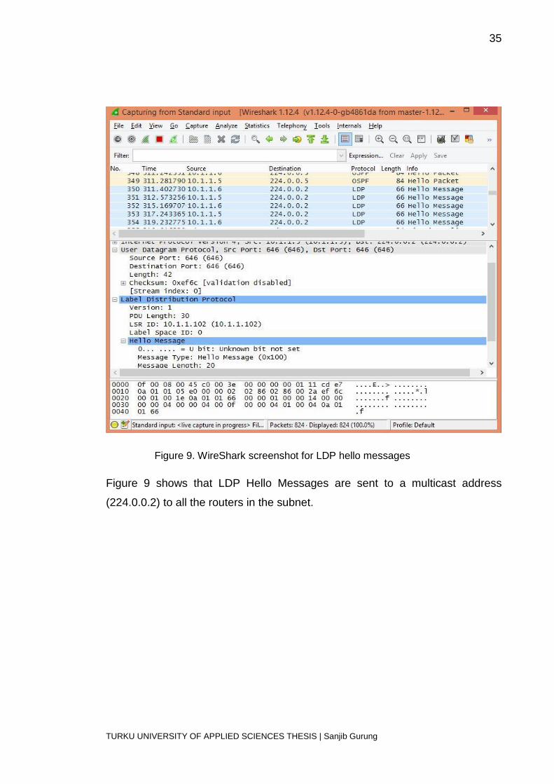
Figure 9. WireShark screenshot for LDP hello messages
Figure 9 shows that LDP Hello Messages are sent to a multicast address
(224.0.0.2) to all the routers in the subnet.
36
TURKU UNIVERSITY OF APPLIED SCIENCES THESIS | Sanjib Gurung
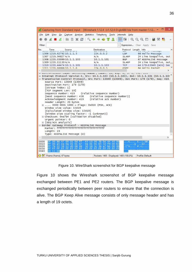
Figure 10. WireShark screenshot for BGP keepalive message
Figure 10 shows the Wireshark screenshot of BGP keepalive message
exchanged between PE1 and PE2 routers. The BGP keepalive message is
exchanged periodically between peer routers to ensure that the connection is
alive. The BGP Keep Alive message consists of only message header and has
a length of 19 octets.
37
TURKU UNIVERSITY OF APPLIED SCIENCES THESIS | Sanjib Gurung
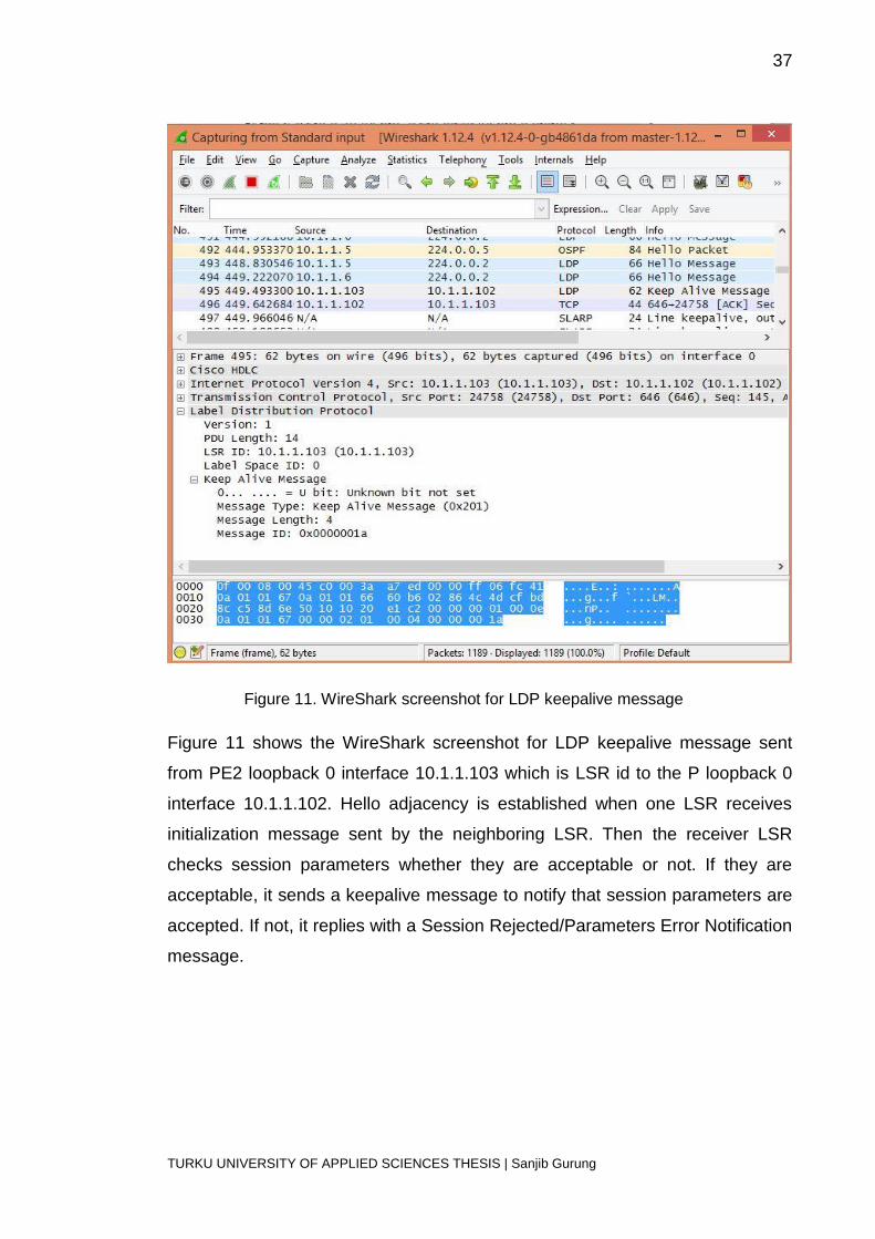
Figure 11. WireShark screenshot for LDP keepalive message
Figure 11 shows the WireShark screenshot for LDP keepalive message sent
from PE2 loopback 0 interface 10.1.1.103 which is LSR id to the P loopback 0
interface 10.1.1.102. Hello adjacency is established when one LSR receives
initialization message sent by the neighboring LSR. Then the receiver LSR
checks session parameters whether they are acceptable or not. If they are
acceptable, it sends a keepalive message to notify that session parameters are
accepted. If not, it replies with a Session Rejected/Parameters Error Notification
message.

38
TURKU UNIVERSITY OF APPLIED SCIENCES THESIS | Sanjib Gurung
Table 2 shows the LIB table in PE1. The LIB table is an MPLS table where all
the labels are stored. It contains all the local labels and mapping of the labels
which are received from the adjacent routers.
Table 4. LIB table
Table 3 shows the LFIB table which is a MPLS table used by routers to make decision
where to forward the labeled packets.
Table 5. LFIB table

39
TURKU UNIVERSITY OF APPLIED SCIENCES THESIS | Sanjib Gurung
6 CONCLUSION
The thesis discusses the configuration of a MPLS VPN over an IPv4 network
and also describes the advantages of MPLS VPN over traditional IP routing.
This thesis documents the configuration for the establishment of an MPLS VPN
network. The thesis explains the features of MPLS VPN that helped to replace
Frame Relay, ATM, dedicated leased lines and offers a new option for WAN
connectivity. Today, most of the enterprises are interested in MPLS VPN
because of performance maximization and cost minimization benefits provided
by it. MPLS VPN services provide significant bandwidth between service
providers’ network and customers’ site to fulfill the requirements of VoIP.
Because of these features like scalable bandwidth, VoIP with CoS,
convergence of video, voice and data in a single infrastructure, MPLS VPN has
become the leading technology in IP technology.
The main objective of this thesis was to determine the importance of applying
MPLS VPN in the traditional IPv4 network. In this investigation, we focused on
assessing of the routing traffic to make a better understanding of different
communication protocols that are involved in MPLS VPN network. These thesis
objectives were achieved by going through the relevant journals, and books and
by implementing the actual demonstration. The practical work was carried out
with a Graphical network simulator-3 (GNS3). Different protocols headers were
captured with the help of Wireshark network analyzer that helped to examine
the various protocol headers.
40
TURKU UNIVERSITY OF APPLIED SCIENCES THESIS | Sanjib Gurung
REFERENCES
[1] Rouse, Margaret. Multiprotocol Label Switching (MPLS). [Online] Available from:
http://searchenterprisewan.techtarget.com/definition/Multiprotocol-Label-Switching
.[Accessed: 12th June 2015]
[2] Johnson, Johna Till. (2007) MPLS explained. [Online] Available from:
http://www.networkworld.com/article/2297171/network-security/mpls-explained.html .
[Accessed: 10th June 2015]
[3] “Simulation of ip traffic engineering improvement using MPLS, [Online] Available
from: http://www.slideshare.net/ameliakot/fyp-presentation-15100528 [Accessed: 1st
May 2015]
[4] Ine. (2010) The MPLS Forwarding Plane. [Online] Available from:
http://blog.ine.com/2010/02/21/the-mpls-forwarding-plane/ [Accessed: 19th July]
[5] Celtdra, Aragoen. (2011) Archive for the ‘MPLS’ category: MPLS concepts. [Online]
Available from: http://routemyworld.com/category/mpls/ . [Accessed: 29th April]
[6] Ghein, Luc De. (2006) MPLS Fundamentals. Cisco Press.
[7] Ine. (2010) MPLS Control Plane and Forwarding Plane Interaction. [Online]
Available from: http://blog.ine.com/2010/02/28/mpls-control-plane-and-forwarding-
plane-interaction/ . [Accessed: 21st June 2015]
[8] Evershed, Sean. (2015) Under the Hood of MPLS VPNS-Part 1. [Online] Available
from:https://learningnetwork.cisco.com/blogs/community_cafe/2015/03/12/under-the-
hood-of-mpls-vpns-part-1-by-sean-evershed . [Accessed: 28th June 2015]
[9] “Configuring a Basic MPLS VPN”, [Online] Available from:
http://www.cisco.com/c/en/us/support/docs/multiprotocol-label-switching-
mpls/mpls/13733-mpls-vpn-basic.html . [Accessed: 13th July 2015]
[10] “Basic MPLS VPN Configuration”, [Online] Available from:
http://netcerts.net/basic-mpls-vpn-configuration/ . [Accessed : 7th July 2015]
[11] “Configuring the LDP Timer for Hello Messages”, [Online] Available from:
https://www.juniper.net/documentation/en_US/junos15.1/topics/usage-guidelines/mpls-
configuring-the-interval-for-ldp-hello-messages.html [Accessed: 15th August 2015]
Related Documents