University of Southern Queensland Faculty of Engineering & Surveying Implementation of JPEG-2000 Standard for the Next Generation Image Compression A dissertation submitted by LOH, Chew Ping in fulfilment of the requirements of ENG4112 Research Project towards the degree of Bachelor of Engineering (Electrical, Electronic Engineering) Submitted: October, 2004

Welcome message from author
This document is posted to help you gain knowledge. Please leave a comment to let me know what you think about it! Share it to your friends and learn new things together.
Transcript

University of Southern Queensland
Faculty of Engineering & Surveying
Implementation of JPEG-2000 Standard for the
Next Generation Image Compression
A dissertation submitted by
LOH, Chew Ping
in fulfilment of the requirements of
ENG4112 Research Project
towards the degree of
Bachelor of Engineering (Electrical, Electronic
Engineering)
Submitted: October, 2004
Abstract
With the increasing use of multimedia technologies, image compression requires
higher performance as well as new functionality. This leads to the emerge of a
new image compression standard, JPEG-2000.
This project seeks to investigate the compression technique of JPEG-2000 stan-
dard. The project scope can be categorised into three areas, understanding of ma-
jor functional blocks of JPEG-2000, setting up an simulation software in C/C++
programming language and investigate the algorithm’s performance and compu-
tational complexity of the standard.
The major functional blocks of JPEG-2000, such as discrete wavelet transform
(DWT) and embedded block coding with optimised truncation (EBCOT), are
particularly focused.
The simulation software which consists of a Windows Bitmap and JPEG-2000
codestream transcoder is developed with additional function program to iden-
tify computational intensive blocks in the transcoder. A graphical user interface
(GUI) is also incorporated to simplified transcoder usage.
The execution time for compression and decompression of each functional block
is investigated. A compatibility test is also carried out between the developed
software and other software packages available in the market. In addition, JPEG-
2000 and JPEG computational complexity and image quality are compared.

University of Southern Queensland
Faculty of Engineering and Surveying
ENG4111/2 Research Project
Limitations of Use
The Council of the University of Southern Queensland, its Faculty of Engineering
and Surveying, and the staff of the University of Southern Queensland, do not
accept any responsibility for the truth, accuracy or completeness of material
contained within or associated with this dissertation.
Persons using all or any part of this material do so at their own risk, and not at
the risk of the Council of the University of Southern Queensland, its Faculty of
Engineering and Surveying or the staff of the University of Southern Queensland.
This dissertation reports an educational exercise and has no purpose or validity
beyond this exercise. The sole purpose of the course pair entitled “Research
Project” is to contribute to the overall education within the student’s chosen
degree program. This document, the associated hardware, software, drawings,
and other material set out in the associated appendices should not be used for
any other purpose: if they are so used, it is entirely at the risk of the user.
Prof G Baker
Dean
Faculty of Engineering and Surveying

Certification of Dissertation
I certify that the ideas, designs and experimental work, results, analyses and
conclusions set out in this dissertation are entirely my own effort, except where
otherwise indicated and acknowledged.
I further certify that the work is original and has not been previously submitted
for assessment in any other course or institution, except where specifically stated.
LOH, Chew Ping
00311337887
Signature
Date

Acknowledgments
This dissertation would never be possible without the generous help and constant
encouragement that I received from numerous people.
First, I would like to express my deepest gratitude to my project supervisor, Dr.
Wei Xiang for his expert guidance throughout the project and his responsiveness
to my enquiries has benefited me greatly.
I would also like to thank my friends, who are always there to provide me with
moral support and encouragement during the difficult times. Thanks for having
faith in me.
Last but not least, I would like to express gratitude towards my family members
for their tremendous care and understanding during my bachelor study.
LOH, Chew Ping
University of Southern Queensland
October 2004

Contents
Abstract i
Acknowledgments iv
List of Figures vi
List of Tables vii
Chapter 1 Introduction 1
1.1 Background . . . . . . . . . . . . . . . . . . . . . . . . . . . . . . 1
1.2 JPEG-2000 . . . . . . . . . . . . . . . . . . . . . . . . . . . . . . 2
1.3 Project Objectives . . . . . . . . . . . . . . . . . . . . . . . . . . 3
1.4 Overview of the Dissertation . . . . . . . . . . . . . . . . . . . . . 3
Chapter 2 JPEG-2000 Codec Structure 5
2.1 Chapter Overview . . . . . . . . . . . . . . . . . . . . . . . . . . . 5
2.2 JPEG-2000 Codec Structure . . . . . . . . . . . . . . . . . . . . . 6

CONTENTS vi
2.3 Pre-Processing . . . . . . . . . . . . . . . . . . . . . . . . . . . . 6
2.4 Discrete Wavelet Transform (DWT) . . . . . . . . . . . . . . . . . 7
2.4.1 Lifting Scheme in DWT . . . . . . . . . . . . . . . . . . . 11
2.5 Quantisation . . . . . . . . . . . . . . . . . . . . . . . . . . . . . . 12
2.6 Embedded Block Coding with Optimised Truncation (EBCOT) . 13
2.6.1 Tier 1 Coding . . . . . . . . . . . . . . . . . . . . . . . . . 14
2.6.2 Tier 2 Coding . . . . . . . . . . . . . . . . . . . . . . . . . 16
2.7 Chapter Summary . . . . . . . . . . . . . . . . . . . . . . . . . . 18
Chapter 3 Investigation of JPEG-2000 Part-1 Software Implemen-
tation 19
3.1 Chapter Overview . . . . . . . . . . . . . . . . . . . . . . . . . . . 19
3.2 JasPer Program Overview . . . . . . . . . . . . . . . . . . . . . . 20
3.3 JPEG-2000 Codestream Encoder . . . . . . . . . . . . . . . . . . 22
3.4 JPEG-2000 Codestream Decoder . . . . . . . . . . . . . . . . . . 29
3.5 Windows Bitmap (bmp) . . . . . . . . . . . . . . . . . . . . . . . 32
3.5.1 Bitmap Encoder . . . . . . . . . . . . . . . . . . . . . . . 32
3.5.2 Bitmap Decoder . . . . . . . . . . . . . . . . . . . . . . . . 33
3.6 Chapter Summary . . . . . . . . . . . . . . . . . . . . . . . . . . 34
CONTENTS vii
Chapter 4 Development of Simulation Software 35
4.1 Chapter Overview . . . . . . . . . . . . . . . . . . . . . . . . . . . 35
4.2 Library Creation . . . . . . . . . . . . . . . . . . . . . . . . . . . 36
4.3 Graphical User Interface Development . . . . . . . . . . . . . . . 38
4.4 JasGUI Application Test . . . . . . . . . . . . . . . . . . . . . . . 45
4.5 Chapter Summary . . . . . . . . . . . . . . . . . . . . . . . . . . 48
Chapter 5 Experimental Results 49
5.1 Chapter Overview . . . . . . . . . . . . . . . . . . . . . . . . . . . 49
5.2 Computational Complexity . . . . . . . . . . . . . . . . . . . . . . 49
5.3 Comparison with JPEG . . . . . . . . . . . . . . . . . . . . . . . 52
5.4 Compatibility Issues . . . . . . . . . . . . . . . . . . . . . . . . . 57
5.5 Chapter Summary . . . . . . . . . . . . . . . . . . . . . . . . . . 58
Chapter 6 Conclusions and Further Work 59
6.1 Achievement of Project Objectives . . . . . . . . . . . . . . . . . 59
6.2 Further Work . . . . . . . . . . . . . . . . . . . . . . . . . . . . . 61
References 62
Appendix A Project Specification 64

CONTENTS viii
Appendix B Source Code or Data Sheets 66

List of Figures
2.1 JPEG-2000 codec structure of (a) encoder and (b) decoder . . . . 6
2.2 1-D, 2-band Wavelet analysis and synthesis filter banks . . . . . . 7
2.3 Symmetrical extension of input signal at boundaries . . . . . . . . 8
2.4 2-D Wavelet decomposition . . . . . . . . . . . . . . . . . . . . . 9
2.5 2-D Wavelet decomposition of lena, (a) Original, (b) 1-level, (c) 2-level,
(d) 3-level . . . . . . . . . . . . . . . . . . . . . . . . . . . . . . . 10
2.6 General block diagram of lifting scheme . . . . . . . . . . . . . . . 11
2.7 Lifting prediction and update steps of the (5,3) filter bank . . . . 12
2.8 Scalar quantiser with deadzone . . . . . . . . . . . . . . . . . . . 13
2.9 Scan pattern within a code block . . . . . . . . . . . . . . . . . . 14
3.1 Overview of JasPer program . . . . . . . . . . . . . . . . . . . . . 21
3.2 Flowchart of a codestream encoder . . . . . . . . . . . . . . . . . 22
3.3 Flowchart of jpc enc encodemainbody function . . . . . . . . . . . 23

LIST OF FIGURES x
3.4 Flowchart of DWT process . . . . . . . . . . . . . . . . . . . . . . 24
3.5 Flowchart of EBCOT Tier 1 . . . . . . . . . . . . . . . . . . . . . 25
3.6 Flowchart of EBCOT Tier 1 jpc enc enccblk function . . . . . . . 26
3.7 Flowchart of EBCOT Tier 2 . . . . . . . . . . . . . . . . . . . . . 27
3.8 Flowchart of EBCOT Tier 2 jpc enc encpkt function . . . . . . . 28
3.9 Flowchart of a codestream decoder . . . . . . . . . . . . . . . . . 29
3.10 Flowchart of jpc dec decode function . . . . . . . . . . . . . . . . 30
3.11 Flowchart of jpc dec process sod function . . . . . . . . . . . . . . 31
3.12 Flowchart of Bitmap encoder . . . . . . . . . . . . . . . . . . . . 32
3.13 Flowchart of Bitmap decoder . . . . . . . . . . . . . . . . . . . . 33
4.1 JasLib project with JPEG Library . . . . . . . . . . . . . . . . . 38
4.2 Program flow of JasGUI . . . . . . . . . . . . . . . . . . . . . . . 39
4.3 Example of variable names assigned to controls . . . . . . . . . . 40
4.4 ’Transcoder’ and ’Image Viewer’ included in ’Function’ menu . . . 41
4.5 Layout of ’Conversion’ dialog box . . . . . . . . . . . . . . . . . . 41
4.6 Layout of ’Conversion Results’ dialog box . . . . . . . . . . . . . . 42
4.7 Workspace of JasGUI and JasLib . . . . . . . . . . . . . . . . . . 44
4.8 JasGUI application . . . . . . . . . . . . . . . . . . . . . . . . . . 45

LIST OF FIGURES xi
4.9 ’Function’ menu . . . . . . . . . . . . . . . . . . . . . . . . . . . . 45
4.10 Open image file . . . . . . . . . . . . . . . . . . . . . . . . . . . . 46
4.11 Save image file as . . . . . . . . . . . . . . . . . . . . . . . . . . . 46
4.12 Confirmation of entries . . . . . . . . . . . . . . . . . . . . . . . . 47
4.13 Execution time for encoding and decoding process . . . . . . . . . 47
5.1 Compression rate at 0.5 for (a) JPEG-2000 and (b) JPEG . . . . 53
5.2 Compression rate at 0.2 for (a) JPEG-2000 and (b) JPEG . . . . 54
5.3 Compression rate at 0.1 for (a) JPEG-2000 and (b) JPEG . . . . 55
5.4 Compression rate at 0.05 for (a) JPEG-2000 and (b) JPEG . . . . 56

List of Tables
5.1 Execution time of functions in (jpc) encoding . . . . . . . . . . . 50
5.2 Execution time of functions in (jpc) decoding . . . . . . . . . . . 50
5.3 Execution time of functions in (jpc) encoding of various image size 51
5.4 Execution time of functions in (jpc) decoding of various image size 51
5.5 Comparison of execution time between JPEG-2000 and JPEG for var-
ious image size . . . . . . . . . . . . . . . . . . . . . . . . . . . . . 52
5.6 Comparison of JPEG-2000 file size generated by JasPer, Photoshop and
IrfanView . . . . . . . . . . . . . . . . . . . . . . . . . . . . . . . . 57

Chapter 1
Introduction
1.1 Background
In the recent years, digital imaging technology has evolved extensively in ap-
plications from Internet viewing, image archiving to wireless applications. In
additional, the drop in digital imaging equipment and processing costs, changes
the way people collect, store, modify, disseminate and display images.
As higher image quality is expected, manipulation of large amount of data is
unavoidable in the process of extraction for editing, saving and processing. In
order to minimise processing time, requirement on transmission bandwidth and
usage of digital storage media, image compression becomes necessary.
Hence, digital imagery today is looking into standard image compression format
that can provide higher image quality, superior compression rate and ability to
operate seamlessly between products in the industries.
Therefore, much effort has been put into the development of image compression
techniques to meet these requirements and also make provision for wider range
of features for emerging applications.
1.2 JPEG-2000 2
1.2 JPEG-2000
JPEG-2000 is a new digital imaging and compression standard, which uses the
state-of-the-art compression technique based on wavelet technology for its image
coding. It is designed and developed to cater for different types of still images, in-
cluding, grey-level, colour, bi-level and multi-component, hyper-component with
different characteristics.
JPEG-2000 not only addresses the deficiencies of current standards but also pro-
vides a list of features such as, (A. N. Skodras & Ebrahimi 2000)
• Superior low bit rate compression performance
• Lossy and lossless compression in a single codestream
• Progressive transmission by quality, resolution, component, or spatial lo-
cality
• Random access to bitstream
• Region-of-interest (ROI) coding
• Robustness to bit errors
• Compressed domain processing
• Limited memory implementations

1.3 Project Objectives 3
1.3 Project Objectives
This project seeks to investigate JPEG-2000 image compression standard, coding
techniques used, advance features and areas of application. The project involves
the understanding of major functional blocks, such as discrete wavelet trans-
form (DWT), quantisation and embedded block coding with optimised truncation
(EBCOT) of the JPEG-2000 coding standard.
An experimental software framework for JPEG-2000 encoder and decoder, in
C/C++ language, will be developed. In addition, an investigation on the algo-
rithm’s performance on compatibility between the developed software and other
JPEG-2000 software will be performed. Furthermore, the computational com-
plexity, in regard to compression and decompression time of JPEG-2000 and
JPEG standards, will also be examined.
1.4 Overview of the Dissertation
This dissertation is organized as follows:
Chapter 2 gives an overview of JPEG-2000 codec structure with its major func-
tions, such as Discrete Wavelet Transform (DWT) and Embedded Block
Coding with Optimised Truncation (EBCOT) further discussed.
Chapter 3 investigates the software implementation of JPEG- 2000 Part 1 codec
based on the official software reference, JasPer.
Chapter 4 describes the development of a simulation software based on JasPer
with an inclusion of a graphical user interface (GUI). Additional features are
incorporated into the software for the investigation on complexity involved
in JPEG-2000.

1.4 Overview of the Dissertation 4
Chapter 5 discusses the experimental results on computational complexity and
software compatibility of JasPer with other JPEG-2000 software packages
available in the market. In addition, comparison results of JPEG-2000 and
JPEG standards, in regard to execution time and image quality at different
compression rate, are also presented.
Chapter 6 concludes the dissertation with suggestions for further work.

Chapter 2
JPEG-2000 Codec Structure
2.1 Chapter Overview
This chapter provides an overview of JPEG-2000 codec structure. The funda-
mental building blocks of a typical JPEG-2000 codec structure are identified and
listed below.
• Pre-Processing
• Discrete Wavelet Transform (DWT)
• Quantisation
• Embedded Block Coding with Optimised Truncation (EBCOT)
In the following sections, each of these functions will be discussed in greater detail.

2.2 JPEG-2000 Codec Structure 6
2.2 JPEG-2000 Codec Structure
The general codec structure of JPEG-2000 is illustrated in figure 2.1, where the
encoder is given by figure 2.1a and the decoder is given by figure 2.1b. The
decoder structure is basically a reverse process of the encoder, thus, the discussion
on each function will be from the point of view of encoding.
Figure 2.1: JPEG-2000 codec structure of (a) encoder and (b) decoder
2.3 Pre-Processing
The pre-processing stage is essentially a preparation process for the source image
prior to the computation of discrete wavelet transform (DWT).
The source image is first partitioned into rectangular non-overlapping tiles through
tiling. Each of these tiles is compressed independently as though they are separate
images. All tiles have the same nominal dimensions of exact powers of two. Tiling
is an optional process, where it is used for reduction of memory requirements and
efficient extraction of a region of the image.
The codec expects its input sample data to have a nominal dynamic range. If
samples in the component are unsigned, each sample in the component is level
shifted by a factor of −2P−1, where P is number of bits/sample in the component.
For component with signed sample values, no level shifting is required.

2.4 Discrete Wavelet Transform (DWT) 7
Subsequently, the three first components of an image are de-correlated through
component transform to improve the coding efficiency. There are two types of
component transforms, reversible (lossless) and irreversible (lossy). The former
transform (RCT) maps integers to integers while the latter transform (ICT) uses
the YCbCr transform. (M. W. Marcellin & Boliek 2000)
2.4 Discrete Wavelet Transform (DWT)
The Discrete Wavelet Transform (DWT) has several advantages over Discrete
Cosine Transform (DCT), which has been used in the baseline of JPEG. As
DWT is full-frame transform in nature, it de-correlates image across a larger
scale, thus eliminates blocking artifacts at high compression rate. Furthermore,
the use of integer DWT filters allow both lossless and lossy compression within a
single compressed bitstream to be achieved.
Discrete Wavelet Transform (DWT) is in fact a one-dimensional (1-D) filtering
operation follows by a downsampling of factor two on the filtered signal. The
filtering operation is implemented through a pair of low-pass and high-pass filters,
known as analysis filter bank at the encoder end and synthesis filter bank at the
decoder end.
Figure 2.2: 1-D, 2-band Wavelet analysis and synthesis filter banks
2.4 Discrete Wavelet Transform (DWT) 8
The analysis filter bank splits the signal into high and low frequency bands, also
known as subbands. After the filtering operation, the filtered samples, known as
wavelet coefficients, are downsampled, denoted by ↓ 2 in figure 2.2, to maintain
the same number of wavelet coefficients as the original signal samples.
After the 1-D decomposition, the low-pass filtered samples is a blurred representa-
tion of the original signal. While the high-pass filter samples preserve information
such as edges, texture and detail of the original signal, which is need for perfect
reconstruction, PR, of original signal from the low-pass filtered samples.
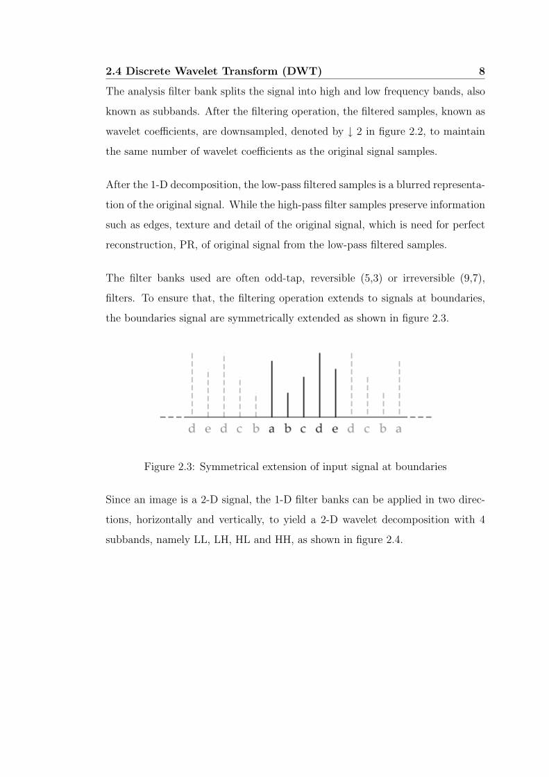
The filter banks used are often odd-tap, reversible (5,3) or irreversible (9,7),
filters. To ensure that, the filtering operation extends to signals at boundaries,
the boundaries signal are symmetrically extended as shown in figure 2.3.
Figure 2.3: Symmetrical extension of input signal at boundaries
Since an image is a 2-D signal, the 1-D filter banks can be applied in two direc-
tions, horizontally and vertically, to yield a 2-D wavelet decomposition with 4
subbands, namely LL, LH, HL and HH, as shown in figure 2.4.

2.4 Discrete Wavelet Transform (DWT) 9
Figure 2.4: 2-D Wavelet decomposition
As image energy is concentrated at the low frequencies, the LL subband can be
further decomposed to yield another 4 subbands at next resolution level. Figure
2.5 illustrates an image component being recursively applied with 2-D filter banks
on the LL bands.

2.4 Discrete Wavelet Transform (DWT) 10
Figure 2.5: 2-D Wavelet decomposition of lena, (a) Original, (b) 1-level, (c)
2-level, (d) 3-level

2.4 Discrete Wavelet Transform (DWT) 11
2.4.1 Lifting Scheme in DWT
In a 2-D DWT decomposition, substantial amount of memory is required for
the storage of the entire image. Hence, an alternative implementation, known
as lifting scheme, is proposed to reduce memory requirement and computational
complexity in DWT.
The lifting scheme is an efficient implementation of the filtering operations at
each level when computing a discrete wavelet transform. There are two stages
involved in the lifting scheme, splitting, also known as lazy transform, and lifting.
(K. Andra & Acharya 2000)
Figure 2.6: General block diagram of lifting scheme
Through the process of lazy transform, the 1-D subband signal is split into its
odd and even sequences, {d0i } and {s0
i } respectively.
Subsequently, these two sets of sequences are to recombine in the lifting steps to
decorrelate the two signals. The lifting step comes in pair of predict and update
lifting step. When the signals are still highly correlated, predicting step is usually
effective. It predicts each odd sample by combining the even samples linearly and
subtracting it from the odd sample of the input sequence to get the prediction
error, {d1i }.

2.5 Quantisation 12
The predicting equation is shown in equation 2.1
d1i = d0
i −1
2(s0
i + s0i+1) (2.1)
Next, the updating stage stores the even samples by adding the modified odd
samples, {d1i }, to its even input sequence to form the updated sequence, {s1
i }.
The updating equation is shown in equation 2.2.
s1i = s0
i +1
4(d1
i−1 + d1i ) (2.2)
In short, the odd samples are predicted by linear interpolation of the neighbouring
even samples and replaced by the prediction error. The even samples are updated
to preserve the mean value of the signal. An example of lifting prediction and
update steps of the (5,3) filter bank is shown in figure 2.7
Figure 2.7: Lifting prediction and update steps of the (5,3) filter bank
2.5 Quantisation
Quantisation is a lossy process by which the coefficients are reduced in precision,
unless the quantisation step is 1 and the coefficients are integers produced by the
RCT, 5/3 wavelet transform. In the case of real mode, coefficients are ICT, 9/7
wavelet transform, the quantiser step sizes used are conveyed to the decoder via
the code stream

2.6 Embedded Block Coding with Optimised Truncation (EBCOT) 13
Figure 2.8: Scalar quantiser with deadzone
For each subband, different quantiser is employed for the transform coefficients
through scalar quantisation with deadzone, figure 2.8. The quantisation process
is defined mathematically as,
qb(u, v) = sign(yb(u, v))
⌊|yb(u, v)|
4b
⌋(2.3)
where 4b is the quantiser step size, yb(u, v) is the input subband signal, and
qb(u, v) denotes the output quantiser indices for the subband. All quantised
transform coefficients are signed values even when the original components are
unsigned. These coefficients are expressed in the sign-magnitude representation
prior to coding. (Rabbani & Joshi 2002)
2.6 Embedded Block Coding with Optimised Trun-
cation (EBCOT)
After the process of wavelet transform and quantisation, the quantised wavelet
coefficients in each subband are partitioned into a set of rectangular code blocks,
but subjected to a few constraints. The nominal height and width of a code
block must be an integer power of two and their product must not exceed 4096.
In addition, the height must not be less than 4. (Adams 2002)
2.6 Embedded Block Coding with Optimised Truncation (EBCOT) 14
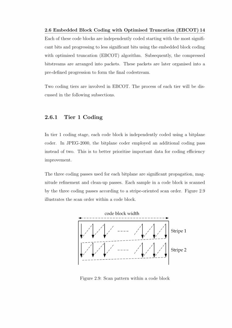
Each of these code blocks are independently coded starting with the most signifi-
cant bits and progressing to less significant bits using the embedded block coding
with optimised truncation (EBCOT) algorithm. Subsequently, the compressed
bitstreams are arranged into packets. These packets are later organised into a
pre-defined progression to form the final codestream.
Two coding tiers are involved in EBCOT. The process of each tier will be dis-
cussed in the following subsections.
2.6.1 Tier 1 Coding
In tier 1 coding stage, each code block is independently coded using a bitplane
coder. In JPEG-2000, the bitplane coder employed an additional coding pass
instead of two. This is to better prioritise important data for coding efficiency
improvement.
The three coding passes used for each bitplane are significant propagation, mag-
nitude refinement and clean-up passes. Each sample in a code block is scanned
by the three coding passes according to a stripe-oriented scan order. Figure 2.9
illustrates the scan order within a code block.
Figure 2.9: Scan pattern within a code block

2.6 Embedded Block Coding with Optimised Truncation (EBCOT) 15
Initially, each sample in the code block will be assigned an insignificant state, ’0’.
During the scan of coding passes, if a non-zero magnitude bit is found, its state
will change to significant, ’1’. The determination for significance of bit is based
on the significance of its eight immediate neighbours. The very first pass in a new
code block is always a clean-up pass because there can be no predicted significant
or refinement bits. The detail of each pass is explained in the following sections.
(D. Taubman & Seroussi 2002)
Significant Propagation Pass. During the first coding pass, significant prop-
agation pass, if an insignificant sample that has the highest possibility of
becoming significant in current bitplane. Its significance will be coded with
a single binary symbol. If the sample happens to be significant, its sign will
be coded using a single binary symbol. A sample will also be predicted to
become significant if any of its eight-connected neighbours is significant.
Magnitude Refinement Pass. The second coding pass will code the next most
significant bit in the sample if sample was found to be significant in the
previous bit plane.
Clean-up Pass. This coding pass will scan 4 samples vertically in the code
block, if all scanned samples are insignificant and have no significant con-
nected neighbours; the number of leading insignificant samples are coded
via aggregation. Any samples indicated as aggregation are skipped. The
scanning continues vertically with the remaining samples with the same
coding method as significant pass.
The symbols generated in cleanup pass are always arithmetically coded, unlike
for symbols generated by significant and refinement passes, which may or may
not be arithmetically coded.

2.6 Embedded Block Coding with Optimised Truncation (EBCOT) 16
The coding employed context dependent binary arithmetic coding with the use
of the MQ-coder. (M. W. Marcellin & Boliek 2000) At the beginning of each
code block, the context models are always reinitialised. Similarly, the arithmetic
codeword is always terminated at the end of each code block.
For ”parallel” mode of execution of coding passes, parallel encoding of all sub-
bitplanes within the code block is enabled through the frequent reset at the
beginning or termination at the end of every sub-bitplane. The significance of
samples in the last row of future sub-bitplanes is ignored, in this mode.
In ”lazy” mode, the number of symbols to be arithmetically coded can be signif-
icantly reduced, after the fourth bitplane is encoded as the arithmetic coder is
bypassed for the first and second coding passes.
2.6.2 Tier 2 Coding
In tier 2 coding stage, the compressed bitstream generated from tier 1 are organ-
ised into packets, through the process of packetisation, to form the final code-
stream.
Since each code block is coded independently, the organisation of bitstreams can
be more flexible. Through different bitstream organisations, features such as
region-of-interest, random access and scalability can be achieved.
The JPEG-2000 codestream consists of a series of connected packets and special
marker segments, where these marker segments are used to signal characteristics
of the codestream.
Packet is a continuous segment in the codestream, it consists of a number of
bitplane coding passes for each code block in a precinct. It can be viewed as one
quality increment for one resolution level at one spatial location.

2.6 Embedded Block Coding with Optimised Truncation (EBCOT) 17
Precinct is a partitioned rectangular region which consists of a grouping of code
blocks for all subbands at a particular resolution level. The packets from each
precinct at all resolution levels in a tile are then combined to form layers, where
it can be viewed as quality increment for the entire image at full resolution.
In order to address specific features and applications, JPEG-2000 supports a
variety of different progression order of packets as listed below. (Rabbani &
Joshi 2002)
Layer-Resolution-Component-Position progression (LRCP), useful in an
image database browsing application where progressively refining image
quality is desirable
Resolution-Layer-Component-Position progression (RLCP), useful in a
client-server application, where different clients might demand for different
resolutions.
Resolution-Position-Component-Layer progression (RPCL), used when
resolution scalability is needed.
Position-Component-Resolution-Layer progression (PCRL), used when
refining image quality at a particular spatial location is desirable
Component-Position-Resolution-Layer progression (CPRL), used only for
a specific image component, where highest quality image for a particular
spatial is desirable.

2.7 Chapter Summary 18
2.7 Chapter Summary
In this chapter, the fundamental blocks of a JPEG-2000 encoder are discussed.
More focus has been placed on major functions such as
• Discrete Wavelet Transform (DWT)
– 1-D and 2-D Wavelet decomposition
– Realisation of Lifting Scheme
• Embedded Block Coding with Optimised Truncation (EBCOT)
– Significant, Refinement and Clean-up Passes
– MQ-coder
– Packetisation, Progression Orders

Chapter 3
Investigation of JPEG-2000
Part-1 Software Implementation
3.1 Chapter Overview
In this chapter, an investigation is carried out on the JasPer project (version
1.700.0), which is an official software-based reference implementation of the codec
specified in the JPEG-2000 Part-1 standard (i.e., ISO/IEC 15444-1). (Adams
2003a)
The JasPer software tool kit provides a means for handling and representing
images in numerous formats, such as JPEG-2000 (JP2), JPEG, PNM, BMP, PGX
and Sun Rasterfile. Its import functionality supports the auto-determination of
the image format, thus, eliminates the need to explicitly identify the format of
coded input data. The software provides a color management engine to allow the
accurate representation of color and partial support for the ICC color profile file
format is also included. (Adams 2003b)
3.2 JasPer Program Overview 20
The JasPer software consists of a library and several application programs, writ-
ten in C programming language. But its library can be easily integrated into
applications written in the C++ programming language.
This software has also been incorporated into numerous commercial and non-
commercial software projects.
The focus of the investigation is placed on identifying the major functions of the
JPEG-2000 coder and the coding techniques employed in JasPer project.
3.2 JasPer Program Overview
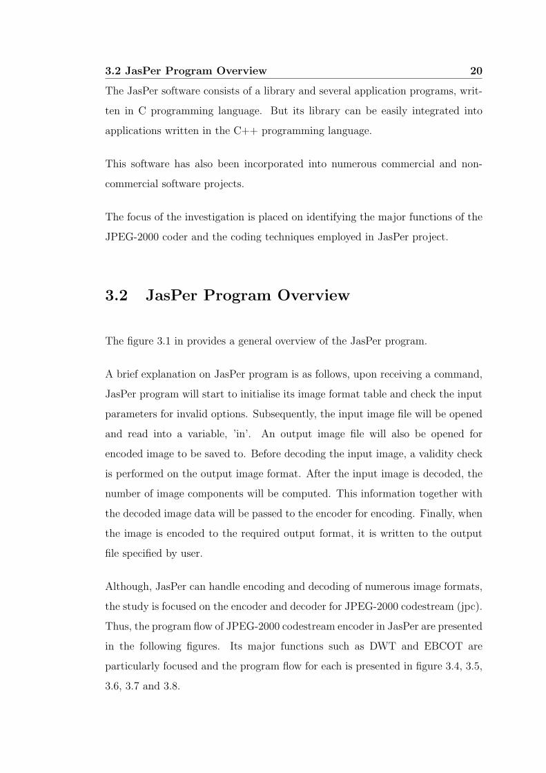
The figure 3.1 in provides a general overview of the JasPer program.
A brief explanation on JasPer program is as follows, upon receiving a command,
JasPer program will start to initialise its image format table and check the input
parameters for invalid options. Subsequently, the input image file will be opened
and read into a variable, ’in’. An output image file will also be opened for
encoded image to be saved to. Before decoding the input image, a validity check
is performed on the output image format. After the input image is decoded, the
number of image components will be computed. This information together with
the decoded image data will be passed to the encoder for encoding. Finally, when
the image is encoded to the required output format, it is written to the output
file specified by user.
Although, JasPer can handle encoding and decoding of numerous image formats,
the study is focused on the encoder and decoder for JPEG-2000 codestream (jpc).
Thus, the program flow of JPEG-2000 codestream encoder in JasPer are presented
in the following figures. Its major functions such as DWT and EBCOT are
particularly focused and the program flow for each is presented in figure 3.4, 3.5,
3.6, 3.7 and 3.8.

3.2 JasPer Program Overview 21
Figure 3.1: Overview of JasPer program
3.3 JPEG-2000 Codestream Encoder 22
3.3 JPEG-2000 Codestream Encoder
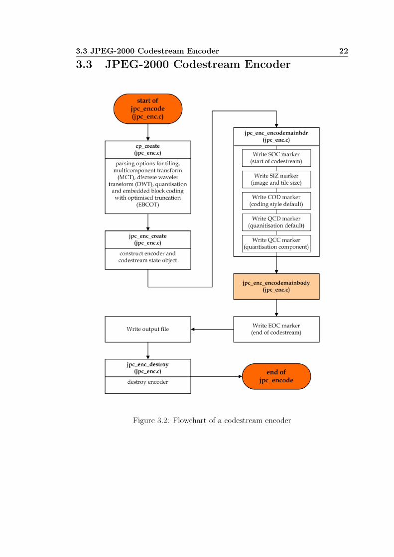
Figure 3.2: Flowchart of a codestream encoder

3.3 JPEG-2000 Codestream Encoder 23
Figure 3.3: Flowchart of jpc enc encodemainbody function

3.3 JPEG-2000 Codestream Encoder 24
Figure 3.4: Flowchart of DWT process

3.3 JPEG-2000 Codestream Encoder 25
Figure 3.5: Flowchart of EBCOT Tier 1

3.3 JPEG-2000 Codestream Encoder 26
Figure 3.6: Flowchart of EBCOT Tier 1 jpc enc enccblk function

3.3 JPEG-2000 Codestream Encoder 27
Figure 3.7: Flowchart of EBCOT Tier 2
3.3 JPEG-2000 Codestream Encoder 28
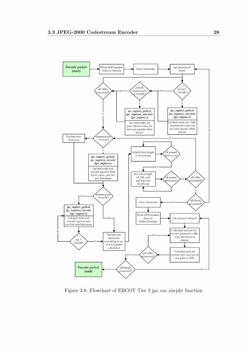
Figure 3.8: Flowchart of EBCOT Tier 2 jpc enc encpkt function

3.4 JPEG-2000 Codestream Decoder 29
3.4 JPEG-2000 Codestream Decoder
With reference to figure 2.1, the decoding process is basically a reverse of the
encoding process. Thus, the decoding process of each function of the decoder
is not elaborated in detail. The general overview of the codestream decoder is
shown in figure 3.9.
Figure 3.9: Flowchart of a codestream decoder

3.4 JPEG-2000 Codestream Decoder 30
Figure 3.10: Flowchart of jpc dec decode function

3.4 JPEG-2000 Codestream Decoder 31
Figure 3.11: Flowchart of jpc dec process sod function

3.5 Windows Bitmap (bmp) 32
3.5 Windows Bitmap (bmp)
Throughout the study, Windows Bitmap format (bmp) is used as the input or
output format for JPEG-2000 codestream encoding and decoding process. Thus,
the general overview of Bitmap encoder and decoder is presented in figure 3.12
and figure 3.13 respectively.
3.5.1 Bitmap Encoder
Figure 3.12: Flowchart of Bitmap encoder

3.5 Windows Bitmap (bmp) 33
3.5.2 Bitmap Decoder
Figure 3.13: Flowchart of Bitmap decoder

3.6 Chapter Summary 34
3.6 Chapter Summary
In this chapter, the functional blocks of the codestream encoder and decoder
from the JasPer software are analysed, with the program flow and linkage of its
major functions presented on flowcharts. In addition, the overview of the Bitmap
encoder and decoder is also illustrated through flowcharts. A list of summary of
the discussed functions is listed below.
• overview of JasPer program
• JPEG-2000 encoder
– main body of the encoder
– DWT
– EBCOT Tier 1
– EBCOT Tier 2
• JPEG-2000 decoder
– marker segment decoding
– main body of the decoder
• Bitmap encoder
• Bitmap decoder

Chapter 4
Development of Simulation
Software
4.1 Chapter Overview
In chaper 3, it was mentioned that the JasPer project consists of a library and
several application programs, written in C programming language. JasPer project
has incorporated applications such as image transcoder, image viewer, image
comparison and information utilities.
In addition, JasPer transcoder is able to provide support for numerous image
format, as mentioned in section 3.1, which is useful for our investigation in JPEG-
2000 software implementation to be discussed in chapter 5.
However, the execution of JasPer project has to be under DOS environment.
Hence, it poses unfriendliness to user who is unfamiliar with DOS environment.
In order to provide easy usage to JasPer users and to facilitate the examination
of software implementation of JPEG-2000 Part 1 codec structure in JasPer, a
graphical user interface (GUI), called JasGUI, is developed.

4.2 Library Creation 36
Before the development of JasGUI, the scope of JPEG-2000 codec investigation
work has to be laid out, which is to identify the computational complexity in-
volved, in regard of execution time, for major functions in the encoding and
decoding process of JPEG-2000 codestream.
Therefore, the design of the simulation software will be based on the following,
• to provide simple and easy usage to user for JasPer project.
• to convert image between Windows Bitmap (bmp) and JPEG-2000 code-
stream (jpc) format.
• to display results on encoding and decoding processes
Since the JasPer project in written in C programming language, Microsoft Visual
C++ 6 (MSVC) will be used to develop the simulation software.
4.2 Library Creation
As JasPer project is very comprehensive, some of the applications that are not
required in our investigation work can be eliminated, such as image comparison
and information utilities. Furthermore, the support for numerous image formats
of the transcoder can be reduced to Window Bitmap (bmp) and JPEG-2000
codestream (jpc) formats.
Since JasPer transcoder is an application program itself, the first task is to create
a new library function based on JasPer transcoder.
In short, the main function, main(), of the transcoder is to be amended to a
function, jasper(), and the MSVC compiler will compile the transcoder program
to a library function instead of an application.

4.2 Library Creation 37
Though, this sounds simple, it is not an easy task to accomplish, bacause of the
complex file structure of the JasPer project. As a novice in C/C++ programming,
sorting out the entire file structure is a complicated task. A lot of times, the
declarations, definitions and linkage of the JasPer project are not obvious.
A great amount of time and effort was put into this library creation, which can be
divided into two portions, learn how to build a C library and identify file linkage
in JasPer project.
Learning how to build the library function involved quite a fair bit of practice
and research work, whereas identifying the file linkage in the JasPer project is a
more tedious and difficult part.
In the actual creation of the library, numerous link errors were encountered, due
to the failure to provide extra linkage and definitions required by JasPer project.
Hence, a lot of time and effort was put into resolving this issue.
After going through all the agonies, the steps to create a new JasPer library
function, known as JasLib for the simulation software, are generally summarised
below;
1. a new folder, JasLib, is created in Windows Explorer.
2. the source and header files including its folders of the required functions
from JasPer project folders are copied to JasLib folder
3. a new workspace, Jas, is opened in MSVC.
4. a new project, JasLib, is create under Jas workspace, the source and header
files from JasLib folder are included into the JasLib project, while excluding
header files in the \include\jasper folder.
5. Preprocesser definitions :JAS_WIN_MSVC_BUILD and Additional include di-
rectories :\JasLib\include are inserted into Project Settings.

4.3 Graphical User Interface Development 38
6. a library file, JasLib.lib, is generated when JasLib project is built.
The inclusion of JPEG encoder and decoder into the simulation software is re-
quired, as comparison of JPEG-2000 and JPEG formats will be made in the later
part of the project.
Although JasPer project provides JPEG encoder and decoder, the JPEG library
is not included. Thus, additional JPEG library need to be incorporated and
can be downloaded from http:\\www.ijg.org\. Figure 4.1 shows JPEG library,
jpeglib.lib, being included into JasLib project
Figure 4.1: JasLib project with JPEG Library
4.3 Graphical User Interface Development
For the development of graphical user interface, JasGUI, Microsoft Foundation
Class Library (MFC) is used, as it provides all the advantages found in C++
programming and greatly reduces the amount of code that must be written to
create a Windows program.

4.3 Graphical User Interface Development 39
In addition, the ability to display the input and output image in an image conver-
sion application, is rather important. Thus, in the design of JasGUI, I have incor-
porated the JasPer transcoder, for image conversion, and JasPer image viewer.
The program flow of the transcoder and image viewer functions is shown in figure
4.2
Figure 4.2: Program flow of JasGUI

4.3 Graphical User Interface Development 40
The development of JasGUI can be divided into two parts, layout design and
user’s option processing.
The JasPer transcoder requires basic input parameters, such as input file, output
file and output file format to be specified before activating its decoding and
encoding process. Therefore, in the design of JasGUI, the collection of these
basic parameters is looked into.
In MFC environment, layout designing is rather simple, a control toolbar is pro-
vided for selection of edit boxes, push buttons, static boxes and etc. The controls
that are used as storage for user’s input are assigned with a variable name using
MFC ClassWizard. These variable names are used in programming functions for
JasGUI later.
Figure 4.3: Example of variable names assigned to controls
During the development of GUI, difficulties are encountered in programming func-
tions to retrieve and process user’s input. Hence, a significant amount of research
work is involved, in order to program functions under MFC environment. The
programming of function calls, capturing inputs, display infomation and variable
types conversion are some examples of difficulties encountered.

4.3 Graphical User Interface Development 41
The steps involved in the development of JasGUI are summarised below.
1. a new MFC project, JasGUI, is created in MSVC.
2. on the window ’Mainframe’, two functions, ’Transcoder’ and ’Image Viewer’,
are created.
Figure 4.4: ’Transcoder’ and ’Image Viewer’ included in ’Function’ menu
3. a ’Conversion’ dialog box is designed to display input and output filenames
for user’s to verify his selections.
Figure 4.5: Layout of ’Conversion’ dialog box

4.3 Graphical User Interface Development 42
4. a ’Conversion Results’ dialog box is designed to display encoding and de-
coding process results.
Figure 4.6: Layout of ’Conversion Results’ dialog box
5. programming of functions for ’Mainframe’, ’Conversion’ and ’Conversion
Results’ and etc. The ’Image Viewer’ source codes are listed as an example.
The full source code listings for JasGUI are available in Appendix B.
void CMainFrame::OnFunctionViewer()
{
CString o_OpenPathName;
// Open File Dialog Box
CFileDialog openfiledlg(TRUE, NULL, NULL,
OFN_HIDEREADONLY | OFN_OVERWRITEPROMPT,
"BMP|*.bmp|JPC|*.jpc|JP2|*.jp2|JPG|*.jpg|", NULL);

4.3 Graphical User Interface Development 43
// Display ’Open’ dialog box
if(openfiledlg.DoModal() == IDOK)
{
o_OpenPathName = openfiledlg.GetPathName();
char *sz_OpenImagePathName;
sz_OpenImagePathName=(LPSTR)(LPCTSTR)m_OpenPathName;
int argc = 2;
char *argv[2];
// Parameters for Image Viewer function
argv[0] = "jiv";
argv[1] = sz_OpenImagePathName;
// Call Image Viewer function
jiv(argc, argv);
}
}

4.3 Graphical User Interface Development 44
Before the simulation software can be tested, the libraries and GUI are linked by
specifying their project dependencies.
Figure 4.7: Workspace of JasGUI and JasLib
In addition, in the source files for the transcoder, clock() function is added to
keep track the execution time for each function of interests.

4.4 JasGUI Application Test 45
4.4 JasGUI Application Test
The following figures show the result and output of each stage when JasGUI is
executed.
1. Execute the application, JasGUI.
Figure 4.8: JasGUI application
2. Select ’Transcoder’ function, under ’Function’ menu.
Figure 4.9: ’Function’ menu
4.4 JasGUI Application Test 46
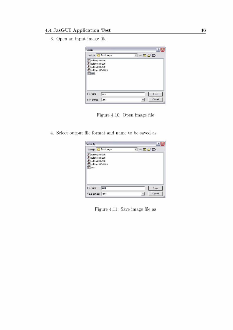
3. Open an input image file.
Figure 4.10: Open image file
4. Select output file format and name to be saved as.
Figure 4.11: Save image file as

4.4 JasGUI Application Test 47
5. Verify input and output file names are correct.
Figure 4.12: Confirmation of entries
6. Decoding and encoding execution time are displayed.
Figure 4.13: Execution time for encoding and decoding process

4.5 Chapter Summary 48
4.5 Chapter Summary
In this chapter, the development of simulation software for the investigation of
JasPer program is discussed.
The development of the software are divided into three parts,
1. Creation of JasLib library.
2. Design and Programming of JasGUI.
3. JasGUI application test.

Chapter 5
Experimental Results
5.1 Chapter Overview
This chapter will investigate the computational complexity involved in the JPEG-
2000 codec, its comparison with the current standard, JPEG and software com-
patibility of JasPer with other market available JPEG-2000 software packages.
5.2 Computational Complexity
As JPEG-2000 is designed to address areas where current standards fail to per-
form, and with additional features incorporated, the increase in codec complexity
is unavoidable.
In the section, the computational complexity of JPEG-2000 is investigated. The
experiment will identify the encoding and decoding time required for the conver-
sion between bitmap format (bmp) and JPEG-2000 codestream (jpc).

5.2 Computational Complexity 50
In this experiment, the JPEG-2000 codec structure is breakdown into its major
functions, such as pre-processing, discrete wavelet transform (DWT), quantisa-
tion and embedded block coding with optimised truncation (EBCOT) tier 1 and
2, so that the execution time required for each function can be determined.
In order to conduct this experiment, a test image, ”lena”, in bitmap format of
size 256 * 256 with 24 bits per pixel, is used. In this experiment, lossless mode
is used.
The execution time for each function in the process of encoding and decoding to
and from JPEG-2000 codestream are shown in table 5.1 and table 5.2 respectively.
Encoder Execution time (ms)
Pre-Processing 42.4 25%
DWT 30.0 18%
Quantisation 6.2 4%
EBCOT Tier 1 90.2 53%
EBCOT Tier 2 2.0 1%
Total 170.8 100%
Table 5.1: Execution time of functions in (jpc) encoding
Decoder Execution time (ms)
Post-Processing 2.0 2 %
Reverse DWT 30.0 29 %
De-quantisation 0.0 0 %
EBCOT Tier 1 70.2 69 %
EBCOT Tier 2 0.0 0 %
Total 102.2 100 %
Table 5.2: Execution time of functions in (jpc) decoding

5.2 Computational Complexity 51
The tabulated results obtained shows that EBCOT is the most complex function
involved in the encoding and decoding processes. With Tier 1 coding contributes
to 53% and 69% of the total execution time for encoding and decoding process
respectively.
This experiment is further extended to the use of different image size, 200*150,
400*300, 800*600 and 1600*1200. The results obtained are shown in table 5.3
and 5.5.
Image Size 200*150 400*300 800*600 1600*1200
Execution time (ms) % (ms) % (ms) % (ms) %
Pre-Processing 27 15 70 11 284 12 1092 13
DWT 10 6 47 7 180 8 764 9
Quantisation 10 6 13 2 53 2 197 2
EBCOT Tier 1 127 70 500 75 1716 73 6133 71
EBCOT Tier 2 7 4 34 5 110 5 404 5
Total 181 100 664 100 2343 100 8589 100
Table 5.3: Execution time of functions in (jpc) encoding of various image size
Image Sizes 200*150 400*300 800*600 1600*1200
Execution time (ms) % (ms) % (ms) % (ms) %
Post-Processing 7 5 13 3 83 5 334 6
Reverse DWT 10 8 47 10 180 10 761 13
De-quantisation 0 0 0 0 0 0 0 0
EBCOT Tier 1 110 87 414 87 1455 85 4980 81
EBCOT Tier 2 0 0 0 0 0 0 0 0
Total 127 100 474 100 1719 100 6076 100
Table 5.4: Execution time of functions in (jpc) decoding of various image size

5.3 Comparison with JPEG 52
From the tables above, EBCOT Tier 1 coding is identified to be the most com-
putational intensive function in the encoding and decoding of JPEG-2000 code-
stream regardless of image size used.
5.3 Comparison with JPEG
In this section, JPEG-2000 and JPEG formats are compared in two factors, exe-
cution time and image quality. As JPEG-2000 has a much complex structure, it
is expected that it will require a longer execution time. The table below shows
the execution time of different image size for the two formats.
Image Size JPEG-2000 JPEG
200*150 180 ms 23 ms
400*300 664 ms 83 ms
800*600 2343 ms 314 ms
1600*1200 8589 ms 1162 ms
Table 5.5: Comparison of execution time between JPEG-2000 and JPEG for
various image size
JPEG is known to have poor performance in compressed compound document,
which contains text and natural images, due to the fact that it was optimised for
natural images. In addition, at low bit rate, JPEG compressed images possessed
undesirable blocky artifacts.
The following figures provide comparisons of an image compressed both with
JPEG-2000 and JPEG at different compression rates.

5.3 Comparison with JPEG 53
Figure 5.1: Compression rate at 0.5 for (a) JPEG-2000 and (b) JPEG

5.3 Comparison with JPEG 54
Figure 5.2: Compression rate at 0.2 for (a) JPEG-2000 and (b) JPEG

5.3 Comparison with JPEG 55
Figure 5.3: Compression rate at 0.1 for (a) JPEG-2000 and (b) JPEG

5.3 Comparison with JPEG 56
Figure 5.4: Compression rate at 0.05 for (a) JPEG-2000 and (b) JPEG

5.4 Compatibility Issues 57
From the figures above, it can be concluded that JPEG-2000 provides superior
performance at low bit rates, while blocky artifacts are noticed in JPEG images.
5.4 Compatibility Issues
In this section, the compatibility of JasPer, as an official software reference im-
plementation of JPEG-2000 Part-1 standard, with other JPEG-2000 softwares in
the market is investigated.
Currently, in the market, there are numerous software developed for JPEG-2000.
Among all, Adobe Photoshop (commercial) and IrfanView (non-commercial) soft-
ware packages are selected for this compatibility test.
In the test, test image, in bitmap format, of various sizes are used. Each of these
images is encoded to JPEG-2000 format by JasPer encoder and subsequently
decoded by Adobe Photoshop and IrfanView. Similarly, JasPer decoder is used
to decode JPEG-2000 images encoded by Adobe Photoshop and IrfanView.
The test on JasPer encoder and decoder has indicated that JasPer is compatible
to both Adobe Photoshop and IrfanView. Through this test, it is noticed that
the JPEG-2000 file size generated by JasPer is comparable to commercial and
non-commercial packages.
BMP dimension BMP file size JasPer (JP2) Photoshop (JP2) IrfanView (JP2)
200*150 88 KB 59 KB 59 KB 59 KB
400*300 352 KB 221 KB 221 KB 221 KB
800*600 1407 KB 781 KB 783 KB NA
1600*1200 5626 KB 2639 KB 2644 KB NA
Table 5.6: Comparison of JPEG-2000 file size generated by JasPer, Photoshop
and IrfanView

5.5 Chapter Summary 58
5.5 Chapter Summary
This chapter has investigated the followings,
• Computational complexity
– Pre-Processing / Post-Processing
– Forward DWT / Inverse DWT
– Quantisation / De-quantisation
– EBCOT Tier 1 and 2 coding
• Comparison with JPEG
– execution time
– image quality
• Software compatibility of JasPer
– with Adobe Photoshop and IrfanView
– comparison of file sizes with Adobe Photoshop and IrfanView
The JasGUI software developed, described in chapter 4, is used to conduct most
of the experiments mentioned in this chapter.

Chapter 6
Conclusions and Further Work
6.1 Achievement of Project Objectives
The following objectives have been addressed:
Overview of JPEG-2000 Chapter 2 presented the concept of JPEG-2000 codec
structure. The major functions of JPEG-2000 such as DWT and EBCOT
are extensively researched in order to gain better understanding for each.
Investigation of JPEG-2000 Part-1 Software Implementation Chapter 3
presented an overview of JasPer program. The JPEG-2000 codestream en-
coder and decoder are focused and numerous flowcharts are drawn to pro-
vide a better graphical view on the linkage between each functions. For the
major functions, a more detailed internal flow within the function is also
illustrated.

6.1 Achievement of Project Objectives 60
Development of Simulation Software Chapter 4 presented the creation of a
library function and the development of a graphical user interface to the
JPEG-2000 transcoder. Additional functions are developed such that ex-
perimental results for algorithm performance and computational complexity
can be displayed.
Experimental Results Chapter 5 presented the simulation results on the algo-
rithm’s performance of the encoding and decoding process. The execution
time for each function is displayed to show its computational complexity.
The compatibility of the development software with other similar, commer-
cial and non-commercial, software packages are tested.
The results of the comparison of JPEG-2000 and JPEG, in regard to their
compression and decompression time and image quality at different com-
pression rate, are presented.

6.2 Further Work 61
6.2 Further Work
There are several areas for possible further development. These areas include:
• Further testing to identify which section of EBCOT contributes to the long
execution time.
• The reduction of execution time in compressing and decompressing for
EBCOT.
• The optimisation of the program code for implementation on embedded
systems to target potential commercial markets.
• Enhancement on the simulation software,
1. to output conversion results to a savable format such as text.
2. to incorporate rate control function so that lossy compression can be
performed.
3. to include a image display window so that user can preview the input
image before selection.

References
A. N. Skodras, C. C. & Ebrahimi, T. (2000), ‘JPEG 2000: The upcoming still
image compression standard’, Proceedings of the 11th Portuguese Conference
on Pattern Recognition pp. 359–366.
A. N. Skodras, C. C. & Ebrahimi, T. (2001), ‘The JPEG 2000 still image com-
pression standard’, IEEE Signal Processing Magazine pp. 36–58.
Adams, M. D. (2002), ‘The JPEG-2000 still image compression standard’.
Adams, M. D. (2003a), The JasPer Project Home Page.
http://www.ece.uvic.ca/~mdadams/jasper/.
Adams, M. D. (2003b), ‘JasPer software reference manual (version 1.700.0)’.
C. J. Lian, K. F. Chen, H. H. C. & Chen, L. G. (n.d.), ‘Analysis and architecture
design of block-coding engine for EBCOT in JPEG 2000’, IEEE Transactions
on Circuits and Systems For Video Technology 13.
D. Taubman, E. Ordentlich, M. W. & Seroussi, G. (2002), ‘Embedded block
coding in JPEG 2000’, Signal Processing: Image Communication 17, 49–72.
Impoco, G. (2004), ‘JPEG2000 - a short tutorial’.
Independent JPEG Group (2004).
http://www.ijg.org/.
JPEG2000 Homepage (2004).
http://www.jpeg.org/jpeg2000.html.

REFERENCES 63
K. Andra, C. C. & Acharya, T. (2000), ‘Efficient implementation of a set of lifting
based wavelet filters’.
Lawson, S. & Zhu, J. (2002), ‘Image compression using wavelets and JPEG-2000:
a tutorial’, Electroncis and Communication Engineering Journal pp. 112–
121.
M. W. Marcellin, M. J. Gormish, A. B. & Boliek, M. P. (2000), ‘An overview of
JPEG-2000’, IEEE Data Compression Conference pp. 523–541.
MSDN Home (2004).
http://msdn.microsoft.com/.
P. Ogunbona, I. K. & John, P. (2000), ‘JPEG2000 - the new wave in image
compression’, CCTV focus .
Rabbani, M. & Joshi, R. (2002), ‘An overview of the JPEG 2000 still image
compression standard’, Signal Processing: Image Communication 17, 3–48.
Schildt, H. (2003), C/C++ Programmer’s Reference, McGraw-Hill.
Taubman, D. & Rosenbaum, R. (-), ‘Rate distortion optimised interactive brows-
ing of JPEG2000 images’.
Usevitch, B. E. (2001), ‘A tutorial on modern lossy wavelet image compression:
Foundations of JPEG 2000’, IEEE Signal Processing Magazine pp. 22–35.
Visual C++ Tutorial (2004).
http://www.functionx.com/visualc/index.htm.
Wallace, G. K. (1991), ‘The JPEG still picture compression standard’, IEEE
Transactions on Consumer Electronics .
Williams, M. (1998), Visual C++ 6, Sams Publishing.

Appendix A
Project Specification

University of Southern Queensland FACULTY OF ENGINEERING AND SURVEYING
ENG 4111/2 Research Project PROJECT SPECIFICATION
FOR : LOH, Chew Ping TOPIC : Investigation of the Next Generation Image Compression
Standard
SUPERVISORS : Mr Xiang, Wei Dr. Leis, John
PROJECT AIM : This project seeks to investigate the JPEG-2000 image
compression standard. The project will involve understanding the major functional blocks of the JPEG- 2000 coding standard, setting up an experimental software framework using C/C++ language, investigating the algorithm’s performance and the computational complexity of the standard, and analysing embedded implementation issues.
PROGRAMME : Issue A, 24th March 2004 1. Understand fundamental image signal processing/compression concepts and principles,
such as discrete cosine transform (DCT) and entropy coding. 2. Understand the advanced coding principles and features provided by JPEG-2000, such as
discrete wavelet transform (DWT) and embedded block coding with optimised truncation (EBCOT) algorithms.
3. Examine coding techniques used and identify fundamental building blocks of JPEG-2000
coder. 4. Setting up an experimental software framework using C/C++ language. 5. Analyse the algorithm's performance. 6. Examine the computational complexity of the coder. As time permits: 7. Investigate the JPEG-2000 implementation on embedded systems. AGREED: LOH, Chew Ping (Student) , (Supervisors)
31 March 2004 (dated)

Appendix B
Source Code or Data Sheets

67
// MainFrm.cpp : implementation of the CMainFrame class
#include "stdafx.h" #include "JasGUI.h" #include "JasGUIDoc.h"
#include "JasGUIView.h" #include "JasConfirm.h" #include
"MainFrm.h" #include "ImgViewer.h"
#ifdef _DEBUG
#define new DEBUG_NEW
#undef THIS_FILE static char
THIS_FILE[] = __FILE__;
#endif
//////////////////////////////////////////////////////////////////
// CMainFrame
IMPLEMENT_DYNCREATE(CMainFrame, CFrameWnd)
BEGIN_MESSAGE_MAP(CMainFrame, CFrameWnd)
//{{AFX_MSG_MAP(CMainFrame)
ON_WM_CREATE()
ON_COMMAND(ID_FILE_OPEN, OnFileOpen)
ON_COMMAND(ID_FUNCTION_CODER, OnFunctionCoder)
ON_COMMAND(ID_FUNCTION_VIEWER, OnFunctionViewer)
//}}AFX_MSG_MAP
END_MESSAGE_MAP()
static UINT indicators[] = {
ID_SEPARATOR, // status line indicator
ID_INDICATOR_CAPS,
ID_INDICATOR_NUM,
ID_INDICATOR_SCRL,

68
};
//////////////////////////////////////////////////////////////////
// CMainFrame construction/destruction
CMainFrame::CMainFrame() {
// TODO: add member initialization code here
}
CMainFrame::~CMainFrame() { }
int CMainFrame::OnCreate(LPCREATESTRUCT lpCreateStruct) {
if (CFrameWnd::OnCreate(lpCreateStruct) == -1)
return -1;
if (!m_wndToolBar.CreateEx(this, TBSTYLE_FLAT, WS_CHILD |
WS_VISIBLE | CBRS_TOP | CBRS_GRIPPER | CBRS_TOOLTIPS |
CBRS_FLYBY | CBRS_SIZE_DYNAMIC) ||
!m_wndToolBar.LoadToolBar(IDR_MAINFRAME))
{
TRACE0("Failed to create toolbar\n");
return -1; // fail to create
}
if (!m_wndStatusBar.Create(this) ||
!m_wndStatusBar.SetIndicators(indicators,
sizeof(indicators)/sizeof(UINT)))
{
TRACE0("Failed to create status bar\n");
return -1; // fail to create
}

69
// TODO: Delete these three lines if you don’t want the
// toolbar to be dockable
m_wndToolBar.EnableDocking(CBRS_ALIGN_ANY);
EnableDocking(CBRS_ALIGN_ANY);
DockControlBar(&m_wndToolBar);
return 0;
}
BOOL CMainFrame::PreCreateWindow(CREATESTRUCT& cs) {
if( !CFrameWnd::PreCreateWindow(cs) )
return FALSE;
// TODO: Modify the Window class or styles here by
// modifying the CREATESTRUCT cs
return TRUE;
}
//////////////////////////////////////////////////////////////////
// CMainFrame diagnostics
#ifdef _DEBUG void CMainFrame::AssertValid() const {
CFrameWnd::AssertValid();
}
void CMainFrame::Dump(CDumpContext& dc) const {
CFrameWnd::Dump(dc);
}
#endif //_DEBUG
70
//////////////////////////////////////////////////////////////////
// CMainFrame message handlers
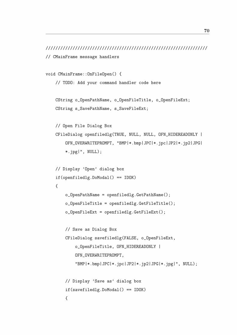
void CMainFrame::OnFileOpen() {
// TODO: Add your command handler code here
CString o_OpenPathName, o_OpenFileTitle, o_OpenFileExt;
CString s_SavePathName, s_SaveFileExt;
// Open File Dialog Box
CFileDialog openfiledlg(TRUE, NULL, NULL, OFN_HIDEREADONLY |
OFN_OVERWRITEPROMPT, "BMP|*.bmp|JPC|*.jpc|JP2|*.jp2|JPG|
*.jpg|", NULL);
// Display ’Open’ dialog box
if(openfiledlg.DoModal() == IDOK)
{
o_OpenPathName = openfiledlg.GetPathName();
o_OpenFileTitle = openfiledlg.GetFileTitle();
o_OpenFileExt = openfiledlg.GetFileExt();
// Save as Dialog Box
CFileDialog savefiledlg(FALSE, o_OpenFileExt,
o_OpenFileTitle, OFN_HIDEREADONLY |
OFN_OVERWRITEPROMPT,
"BMP|*.bmp|JPC|*.jpc|JP2|*.jp2|JPG|*.jpg|", NULL);
// Display ’Save as’ dialog box
if(savefiledlg.DoModal() == IDOK)
{

71
s_SavePathName = savefiledlg.GetPathName();
s_SaveFileExt = savefiledlg.GetFileExt();
// Assign user’s option to ’Confirmation’ dialog box
JasConfirm Jasdlg;
Jasdlg.m_FromFile = o_OpenPathName;
Jasdlg.m_ToFile = s_SavePathName;
Jasdlg.m_FromExt = o_OpenFileExt;
Jasdlg.m_FileExt = s_SaveFileExt;
Jasdlg.DoModal();
}
}
}
void CMainFrame::OnFunctionCoder() {
// TODO: Add your command handler code here
CString o_OpenPathName, o_OpenFileTitle, o_OpenFileExt;
CString s_SavePathName, s_SaveFileExt;
// Open File Dialog Box
CFileDialog openfiledlg(TRUE, NULL, NULL, OFN_HIDEREADONLY |
OFN_OVERWRITEPROMPT,
"BMP|*.bmp|JPC|*.jpc|JP2|*.jp2|JPG|*.jpg|", NULL);
// Display ’Open’ dialog box
if(openfiledlg.DoModal() == IDOK)
{
o_OpenPathName = openfiledlg.GetPathName();
o_OpenFileTitle = openfiledlg.GetFileTitle();
o_OpenFileExt = openfiledlg.GetFileExt();
72
// Save as Dialog Box
CFileDialog savefiledlg(FALSE, o_OpenFileExt,
o_OpenFileTitle, OFN_HIDEREADONLY |
OFN_OVERWRITEPROMPT,
"BMP|*.bmp|JPC|*.jpc|JP2|*.jp2|JPG|*.jpg|", NULL);
// Display ’Save as’ dialog box
if(savefiledlg.DoModal() == IDOK)
{
s_SavePathName = savefiledlg.GetPathName();
s_SaveFileExt = savefiledlg.GetFileExt();
// Assign user’s option to ’Confirmation’ dialog box
JasConfirm Jasdlg;
Jasdlg.m_FromFile = o_OpenPathName;
Jasdlg.m_ToFile = s_SavePathName;
Jasdlg.m_FromExt = o_OpenFileExt;
Jasdlg.m_FileExt = s_SaveFileExt;
Jasdlg.DoModal();
}
}
}
void CMainFrame::OnFunctionViewer() {
// TODO: Add your command handler code here
CString o_OpenPathName;
// Open File Dialog Box
CFileDialog openfiledlg(TRUE, NULL, NULL, OFN_HIDEREADONLY |

73
OFN_OVERWRITEPROMPT, "BMP|*.bmp|JPC|*.jpc|JP2|*.jp2|JPG|
*.jpg|", NULL);
// Display ’Open’ dialog box
if(openfiledlg.DoModal() == IDOK)
{
o_OpenPathName = openfiledlg.GetPathName();
// Assign image file name to ’Image Viewer’ dialog box
ImgViewer Imgdlg;
Imgdlg.m_OpenImage = o_OpenPathName;
Imgdlg.DoModal();
char *sz_OpenImagePathName;
sz_OpenImagePathName=(LPSTR)(LPCTSTR)m_OpenImage;
// Parameters for imager viewer function
int argc = 2;
char *argv[2];
argv[0] = "jiv";
argv[1] = sz_OpenImagePathName;
jiv(argc, argv);
}
}
//////////////////////////////////////////////////////////////////

74
// JasConfirm.cpp : implementation file
#include "stdafx.h" #include "JasGUI.h" #include "JasGUIDoc.h"
#include "JasGUIView.h" #include "JasConfirm.h" #include
"MainFrm.h"
#include "jasper/jasper.h"
#ifdef _DEBUG
#define new DEBUG_NEW
#undef THIS_FILE static char
THIS_FILE[] = __FILE__;
#endif
//////////////////////////////////////////////////////////////////
// JasConfirm dialog
JasConfirm::JasConfirm(CWnd* pParent /*=NULL*/)
: CDialog(JasConfirm::IDD, pParent)
{
//{{AFX_DATA_INIT(JasConfirm)
m_FromFile = _T("");
m_ToFile = _T("");
m_FileExt = _T("");
m_RateRange = 0;
m_FromExt = _T("");
m_OpenImage = _T("");
//}}AFX_DATA_INIT
}
void JasConfirm::DoDataExchange(CDataExchange* pDX) {
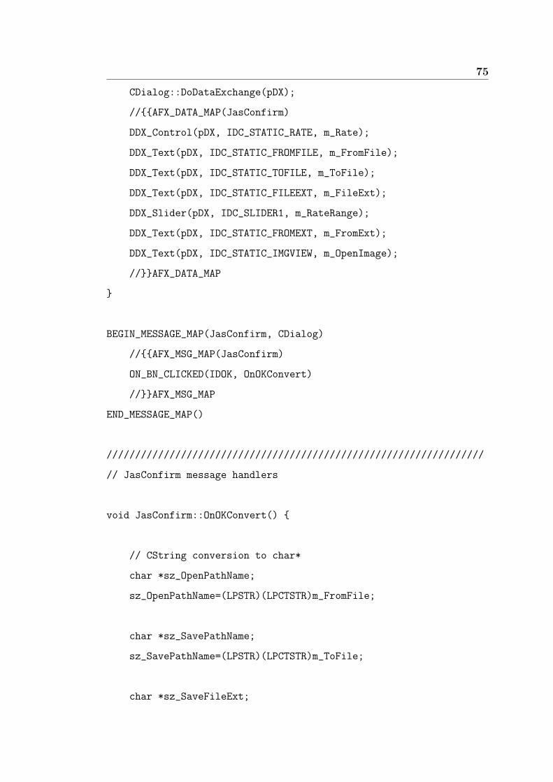
75
CDialog::DoDataExchange(pDX);
//{{AFX_DATA_MAP(JasConfirm)
DDX_Control(pDX, IDC_STATIC_RATE, m_Rate);
DDX_Text(pDX, IDC_STATIC_FROMFILE, m_FromFile);
DDX_Text(pDX, IDC_STATIC_TOFILE, m_ToFile);
DDX_Text(pDX, IDC_STATIC_FILEEXT, m_FileExt);
DDX_Slider(pDX, IDC_SLIDER1, m_RateRange);
DDX_Text(pDX, IDC_STATIC_FROMEXT, m_FromExt);
DDX_Text(pDX, IDC_STATIC_IMGVIEW, m_OpenImage);
//}}AFX_DATA_MAP
}
BEGIN_MESSAGE_MAP(JasConfirm, CDialog)
//{{AFX_MSG_MAP(JasConfirm)
ON_BN_CLICKED(IDOK, OnOKConvert)
//}}AFX_MSG_MAP
END_MESSAGE_MAP()
//////////////////////////////////////////////////////////////////
// JasConfirm message handlers
void JasConfirm::OnOKConvert() {
// CString conversion to char*
char *sz_OpenPathName;
sz_OpenPathName=(LPSTR)(LPCTSTR)m_FromFile;
char *sz_SavePathName;
sz_SavePathName=(LPSTR)(LPCTSTR)m_ToFile;
char *sz_SaveFileExt;

76
sz_SaveFileExt=(LPSTR)(LPCTSTR)m_FileExt;
// Parameters for transcoder function
int argc = 7;
char *argv[7];
argv[0] = "jasper";
argv[1] = "-f";
argv[2] = sz_OpenPathName;
argv[3] = "-F";
argv[4] = sz_SavePathName;
argv[5] = "-T";
argv[6] = sz_SaveFileExt;
// Call transcoder function
if(jasper(argc, argv))
{
CString dispinfo1, dispinfo2, dispitems1, dispitems2,
dispexe1, dispexe2;
// Format results from transcoder function
dispinfo1.Format("Input image: %s\nImage size: %d X %d
\nNo. of Components: %d\t\t(%d bits/pixel)\n", m_FromFile,
height, width, numcmpt, (numcmpt*depth));
dispinfo2.Format("Output image: %s\n",m_ToFile);
dispitems1.Format("\nPre-Processing\nDWT\nQuantisation
\nEBCOT Tier 1\nEBCOT Tier 2");
dispitems2.Format("\nPost-Processing\nInverse DWT\n
De-Quantisation\nEBCOT Tier 1\nEBCOT Tier 2");

77
dispexe1.Format("Encoding time: %d (ms)\n\t%d\n\t%d\n\t%d
\n\t%d\n\t%d\n",enctime, prepro, dwt, quan, enct1, enct2);
dispexe2.Format("Decoding time: %d (ms)\n\t%d\n\t%d\n\t%d
\n\t%d\n\t%d\n",(dectime-colour), postpro, invdwt,
dequan, dect1, dect2);
// Assign the formatted results to ’Conversion Results’
dialog box
JasResults JasResdlg;
JasResdlg.m_ImageInfo = dispinfo1;
JasResdlg.m_OutFile = dispinfo2;
JasResdlg.m_EncItems = dispitems1;
JasResdlg.m_DecItems = dispitems2;
JasResdlg.m_EncTime = dispexe1;
JasResdlg.m_DecTime = dispexe2;
JasResdlg.DoModal();
}
CDialog::OnCancel();
}
void JasConfirm::OnCancel() {
CDialog::OnCancel();
}
//////////////////////////////////////////////////////////////////

78
// JasResults.cpp : implementation file
#include "stdafx.h"
#include "JasGUI.h"
#include "JasGUIDoc.h"
#include "JasGUIView.h"
#include "JasConfirm.h"
#include "MainFrm.
#ifdef _DEBUG
#define new DEBUG_NEW
#undef THIS_FILE static char
THIS_FILE[] = __FILE__;
#endif
//////////////////////////////////////////////////////////////////
// JasResults dialog
JasResults::JasResults(CWnd* pParent /*=NULL*/)
: CDialog(JasResults::IDD, pParent)
{
//{{AFX_DATA_INIT(JasResults)
m_ImageInfo = _T("");
m_EncItems = _T("");
m_DecItems = _T("");
m_EncTime = _T("");
m_DecTime = _T("");
m_OutFile = _T("");
//}}AFX_DATA_INIT
}

79
void JasResults::DoDataExchange(CDataExchange* pDX) {
CDialog::DoDataExchange(pDX);
//{{AFX_DATA_MAP(JasResults)
DDX_Text(pDX, IDC_STATIC_INFO, m_ImageInfo);
DDX_Text(pDX, IDC_STATIC_ENCITEMS, m_EncItems);
DDX_Text(pDX, IDC_STATIC_DECITEMS, m_DecItems);
DDX_Text(pDX, IDC_STATIC_ENCTIME, m_EncTime);
DDX_Text(pDX, IDC_STATIC_DECTIME, m_DecTime);
DDX_Text(pDX, IDC_STATIC_OUTFILE, m_OutFile);
//}}AFX_DATA_MAP
}
BEGIN_MESSAGE_MAP(JasResults, CDialog)
//{{AFX_MSG_MAP(JasResults)
// NOTE: the ClassWizard will add message map macros here
//}}AFX_MSG_MAP
END_MESSAGE_MAP()
//////////////////////////////////////////////////////////////////
// JasResults message handlers

80
// ImgViewer.cpp : implementation file
#include "stdafx.h" #include "JasGUI.h" #include "ImgViewer.h"
#include "MainFrm.h"
#ifdef _DEBUG
#define new DEBUG_NEW
#undef THIS_FILE static char
THIS_FILE[] = __FILE__;
#endif
//////////////////////////////////////////////////////////////////
// ImgViewer dialog
ImgViewer::ImgViewer(CWnd* pParent /*=NULL*/)
: CDialog(ImgViewer::IDD, pParent)
{
//{{AFX_DATA_INIT(ImgViewer)
m_OpenImage = _T("");
//}}AFX_DATA_INIT
}
void ImgViewer::DoDataExchange(CDataExchange* pDX) {
CDialog::DoDataExchange(pDX);
//{{AFX_DATA_MAP(ImgViewer)
DDX_Text(pDX, IDC_STATIC_IMAGE, m_OpenImage);
//}}AFX_DATA_MAP
}
BEGIN_MESSAGE_MAP(ImgViewer, CDialog)
//{{AFX_MSG_MAP(ImgViewer)

81
//}}AFX_MSG_MAP
END_MESSAGE_MAP()
//////////////////////////////////////////////////////////////////
// ImgViewer message handlers
void ImgViewer::OnOK() {
// TODO: Add your specialized code here and/or call the base
class
// CString conversion to char*
char *sz_OpenImagePathName;
sz_OpenImagePathName=(LPSTR)(LPCTSTR)m_OpenImage;
// Parameters for imager viewer function
int argc = 2;
char *argv[2];
argv[0] = "jiv";
argv[1] = sz_OpenImagePathName;
jiv(argc, argv);
CDialog::OnOK();
}
//////////////////////////////////////////////////////////////////
Related Documents