VISVESWARAYA TECHNOLOGICAL UNIVERSITY, BELAGAVI NEW HORIZON COLLEGE OF ENGINEERING, BANGALORE Autonomous College Permanently Affiliated to VTU Approved by AICTE Accredited by NAAC with ‘A’ grade PROJECT REPORT ON “IMPLEMENTATION OF DUAL INVERTER FOR REVERSAL SPEED OF DC MOTOR” Submitted in partial fulfilment as a requirement for the award of degree of BACHELOR OF ENGINEERING IN ELECTRICAL AND ELECTRONICS UNDER THE GUIDANCE OF Dr. Mahesh K SUBMITTED BY KAVITHA O 1NH14EE744 NAVYA T.G 1NH14EE747 NIKITA ADARI 1NH14EE749 SUSHMITHA Y 1NH14EE758 June 2018

Welcome message from author
This document is posted to help you gain knowledge. Please leave a comment to let me know what you think about it! Share it to your friends and learn new things together.
Transcript
VISVESWARAYA TECHNOLOGICAL UNIVERSITY, BELAGAVI
NEW HORIZON COLLEGE OF ENGINEERING, BANGALORE Autonomous College Permanently Affiliated to VTU Approved by AICTE Accredited by
NAAC with ‘A’ grade
PROJECT REPORT ON
“IMPLEMENTATION OF DUAL INVERTER FOR REVERSAL
SPEED OF DC MOTOR”
Submitted in partial fulfilment as a requirement for the award of degree of
BACHELOR OF ENGINEERING
IN
ELECTRICAL AND ELECTRONICS
UNDER THE GUIDANCE OF
Dr. Mahesh K
SUBMITTED BY
KAVITHA O 1NH14EE744
NAVYA T.G 1NH14EE747
NIKITA ADARI 1NH14EE749
SUSHMITHA Y 1NH14EE758
June 2018
VISVESWARAYA TECHNOLOGICAL UNIVERSITY, BELAGAVI
NEW HORIZON COLLEGE OF ENGINEERING, BANGALORE
Autonomous College Permanently Affiliated to VTU Approved by AICTE Accredited
by NAAC with ‘A’ grade
DEPARTMENT OF ELECTRICAL AND ELECTRONICS ENGINEERING
CERTIFICATE
This is to certify that the project work entitled “IMPLEMENTATION OF DUAL INVERTER FOR
REVERSAL SPEED OF DC MOTOR” is a bonafide work carried out by STUDENT KAVITHA O
(1NH14EE744), NAVYA T G (1NH14EE747), NIKITA ADARI (1NH14EE749), SUSHMITHA Y
(1NH14EE758) submitted in partial Fulfilment for the award of Bachelor of Engineering degree in
VIII semester of the Visvesvaraya Technological University, Belagavi during the academic year
2017-18. It is certified that all the corrections and suggestions indicated for Internal Assessment have
been incorporated in the report deposited in the Department library. The project work has been
approved as it satisfies the academic requirement in respect of Project Work (10EEP85) prescribed for
BACHELOR OF ENGINEERING DEGREE IN ELECTRICAL AND ELECTRONICS
ENGINEERING.
GUIDE HOD PRINCIPAL
Dr Mahesh K Dr Elumalai Dr Manjunatha
NAME OF THE EXAMINERS SIGN WITH DATE
1
2
Scanned by CamScanner

Scanned by CamScanner

Scanned by CamScanner
Scanned by CamScanner
IMPLEMENTATION OF DUAL INVERTER FOR REVERSAL SPEED OF DC MOTOR
NHCE Department of EEE Page 1
ABSTRACT
The one of the biggest technology in field of electrical engineering is dc motor,
which produces mechanical energy from electrical energy. The one of the
important factor in dc motor is to control the speed, direction of motor change is
characteristic of dc motor. To have high staring torque and adjust the braking
system of dc motor for industrial purpose. The armature voltage is used to
change speed of a dc motor. Different Single phase rectifier is used for adjusting
the voltage of armature. For speed control there are many converter such as half
wave converter, semi converter, full converter and dual converter. The four
quadrant mode is obtained by dual converter using thyristor. For switching
purpose the thyristors are used.
IMPLEMENTATION OF DUAL INVERTER FOR REVERSAL SPEED OF DC MOTOR
NHCE Department of EEE Page 2
ACKNOWLEDGMENT
Gratitude takes three forms –“A feeling from heart, an expression in words and a
giving in return”. We take this opportunity to express our heart-feelings.
I would like to profoundly thank Management of New Horizon College of
Engineering for providing such a healthy environment for successful completion
of project work.
I would like to express my thanks to Dr.Mohan Manghnani, Chairman of
NEW HORIZON EDUCATIONAL INSTITUITIONS and the Principal
Dr.Manjunatha for their encouragement that motivated me for the successful
completion of Project work.
It is an immense pleasure to thank Dr. Elumalai, Professor and Head of
Department for his constant support and encouragement.
Also, I would like to express my deepest sense of gratitude to my Project guide
Dr. Mahesh K, Professor, Department of electrical and electronics engineering
for his constant support and guidance throughout our project work.
Finally, we would like to express our heartfelt thanks to our beloved parents for
their blessings, our friends for their help and wishes for the successful
completion of this project work
KAVITHA O
NAVYA T G
NIKITA ADARI
SUSHMITHA Y
IMPLEMENTATION OF DUAL INVERTER FOR REVERSAL SPEED OF DC MOTOR
NHCE Department of EEE Page 3
CONTENTS
Chapter 1. Introduction Page No.6
Chapter 2. Literature Survey Page No. 9
Chapter 3. Components Required Page No.11
Chapter 4. Methodology Page No.20
Chapter 5. Working Principle of Dual Converter Page No. 21
Chapter 6. Modes of control for the dual converter Page No.24
6.1 Modes Page No.24
6.2 Simultaneous Control or Circulating
Current Control Page No.25
6.2(a) Procedure for Speed Reversal Page No.25
6.2(b) Disadvantages Page No.25
6.3 Non Simultaneous Control or
Circulating current control method Page No.26
6.3(a) Procedure for Speed Reversal Page No. 26
6.3(b) Advantages Page No.26
Chapter 7. Four quadrant operation Page No.27
7.1 Forward Motoring Page No.27
7.2 Forward Braking Page No.28
7.3 Reverse Motoring Page No.28
7.4 Reverse Regenerative Braking Page No.29
Chapter 8. Speed Control Method Page No.30
8.1 Armature Voltage Control Page No.30
IMPLEMENTATION OF DUAL INVERTER FOR REVERSAL SPEED OF DC MOTOR
NHCE Department of EEE Page 4
8.2 Field Control of DC Series motor Page No.31
Chapter 9. Pulse width modulation Page No.33
Chapter 10. Simulation page no.37
Chapter 11. Application Page No.38
Chapter 12. Advantages Page No.40
Chapter 13. Future Scope Page No.42
Chapter 14. Conclusion Page No.43
Chapter 15. Reference. Page No.44
IMPLEMENTATION OF DUAL INVERTER FOR REVERSAL SPEED OF DC MOTOR
NHCE Department of EEE Page 5
LIST OF FIGURES
Fig 1. Motor diagram Page No.6
Fig 2. Project Model Page No.7
Fig 3. Dual Converter Diagram Page No.8
Fig 4. Transformer Page No.12
Fig 5. Bridge Rectifier Page No.13
Fig 6. Voltage Regulator Page No.14
Fig 7. Opto-Coupler Page No.14
Fig 8. Silicon Controlled Rectifier Page No.15
Fig 9. 555 Timer Page No.17
Fig 10. Block diagram Page No.20
Fig 11. Simplified Equivalent diagram
Of DC circuit Page No.21
Fig 12. Thyristor Firing angle graph Page No.22
Fig 13. Basic DC diagram Page No.24
Fig 14. Pulse Width Page No.33
Fig 15. PWM circuit Page No.35
Fig 16. Square Wave Duty Cycle (PWM) Page No.36
Fig 17. Microcontroller pin diagram Page No.40
IMPLEMENTATION OF DUAL INVERTER FOR REVERSAL SPEED OF DC MOTOR
NHCE Department of EEE Page 6
CHAPTER1
INTRODUCTION
MOTOR:
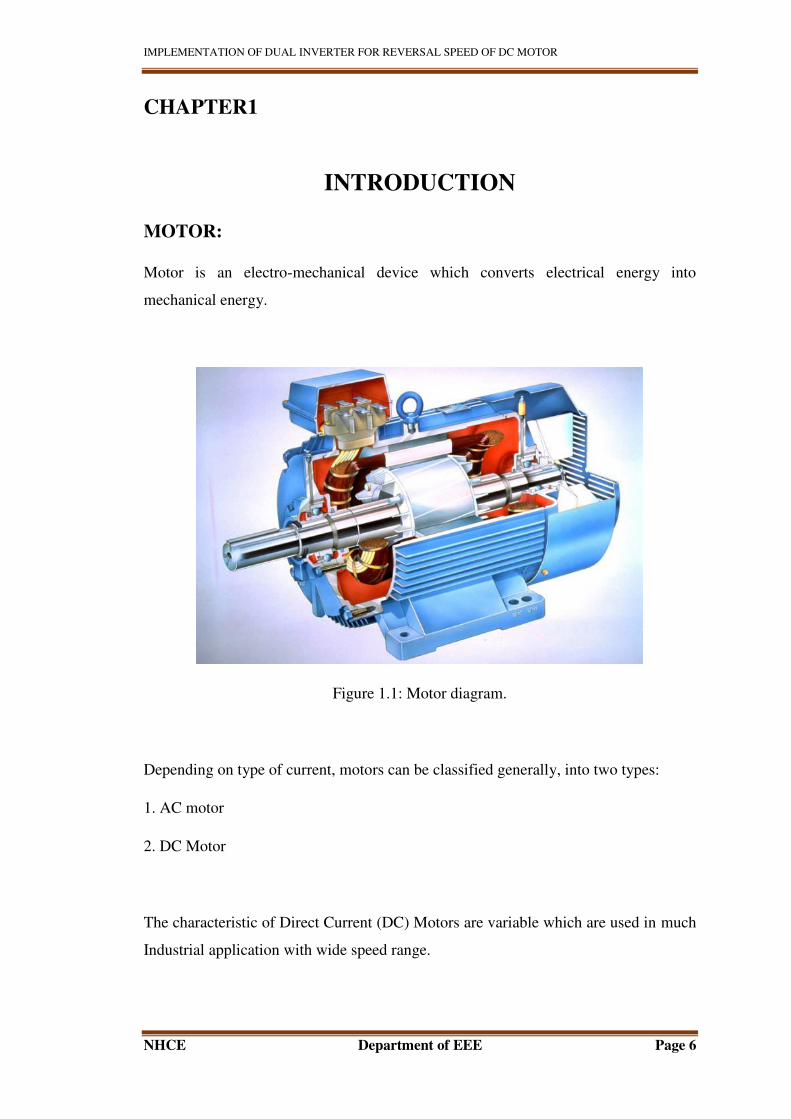
Motor is an electro-mechanical device which converts electrical energy into
mechanical energy.
Figure 1.1: Motor diagram.
Depending on type of current, motors can be classified generally, into two types:
1. AC motor
2. DC Motor
The characteristic of Direct Current (DC) Motors are variable which are used in much
Industrial application with wide speed range.
IMPLEMENTATION OF DUAL INVERTER FOR REVERSAL SPEED OF DC MOTOR
NHCE Department of EEE Page 7
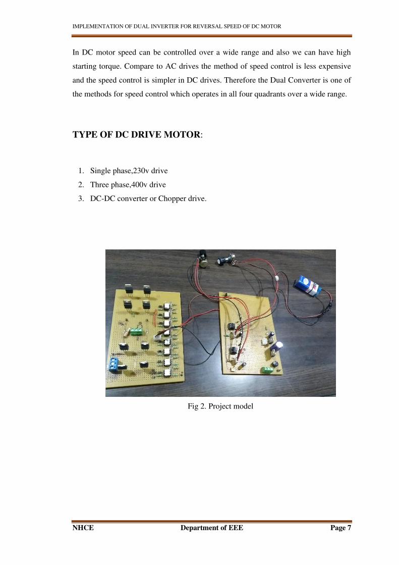
In DC motor speed can be controlled over a wide range and also we can have high
starting torque. Compare to AC drives the method of speed control is less expensive
and the speed control is simpler in DC drives. Therefore the Dual Converter is one of
the methods for speed control which operates in all four quadrants over a wide range.
TYPE OF DC DRIVE MOTOR:
1. Single phase,230v drive
2. Three phase,400v drive
3. DC-DC converter or Chopper drive.
Fig 2. Project model
IMPLEMENTATION OF DUAL INVERTER FOR REVERSAL SPEED OF DC MOTOR
NHCE Department of EEE Page 8
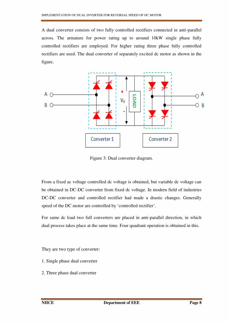
A dual converter consists of two fully controlled rectifiers connected in anti-parallel
across. The armature for power rating up to around 10kW single phase fully
controlled rectifiers are employed. For higher rating three phase fully controlled
rectifiers are used. The dual converter of separately excited dc motor as shown in the
figure.
Figure 3: Dual converter diagram.
From a fixed ac voltage controlled dc voltage is obtained, but variable dc voltage can
be obtained in DC-DC converter from fixed dc voltage. In modern field of industries
DC-DC converter and controlled rectifier had made a drastic changes. Generally
speed of the DC motor are controlled by ‘controlled rectifier’.
For same dc load two full converters are placed in anti-parallel direction, in which
dual process takes place at the same time. Four quadrant operation is obtained in this.
They are two type of converter:
1. Single phase dual converter
2. Three phase dual converter
IMPLEMENTATION OF DUAL INVERTER FOR REVERSAL SPEED OF DC MOTOR
NHCE Department of EEE Page 9
CHAPTER 2
LITERATURE SURVEY
The motor or an electrical motor is a device that has brought about one of the biggest
advancements in the field of engineering and technology ever since the invention of
electricity.
The DC motor is used in most of industrial application such as traction, hoist, arc
welding, mills etc. as the speed control is easy and simple compare to AC motor and
rotation of DC motor can be reversed.
DC motors provide high starting torque which is required for traction applications. In
DC motor control over a large speed range, both below and above the rated speed can
be achieved quite easily.
In general, armature voltage control method is widely used to control the DC drives.
In this method, a controlled rectifier, or chopper is used but due involvement of power
electronics elements, nonlinear torque speed characteristics are observed which are
undesirable for control performance.
Nowadays states of art speed control techniques of DC motor are available. Thyristor
based DC drives with analog and digital feedback control schemes are used Phase
locked loop control technique is also used for precise speed control and zero speed
regulation. In past, many researchers presented various new converter topologies of
DC motor control for different applications of industry, but at the basic level in all of
them thyristor based AC-DC converter are used.
SCR Characteristic for obtaining polarity in either direction of DC motor

IMPLEMENTATION OF DUAL INVERTER FOR REVERSAL SPEED OF DC MOTOR
NHCE Department of EEE Page 10
Pulse width modulation method for speed control which is simple and easy with less
power loss.
IMPLEMENTATION OF DUAL INVERTER FOR REVERSAL SPEED OF DC MOTOR
NHCE Department of EEE Page 11
CHAPTER 3
COMPONENTS REQUIRED
1. Transformer
2. Voltage regulator
3. Bridge rectifier
4. Opto coupler
5. Variable resistor or potentiometer
6. SCR or Thyristor
7. 555 timer
8. Resistor
9. Capacitor
10. Filter
11. Connecting wires
12. Load
1. AC SUPPLY:
The direction can be reversed periodically in alternating current (AC), compare to
direct current flow.
Here 230v supply is given to circuit.
IMPLEMENTATION OF DUAL INVERTER FOR REVERSAL SPEED OF DC MOTOR
NHCE Department of EEE Page 12
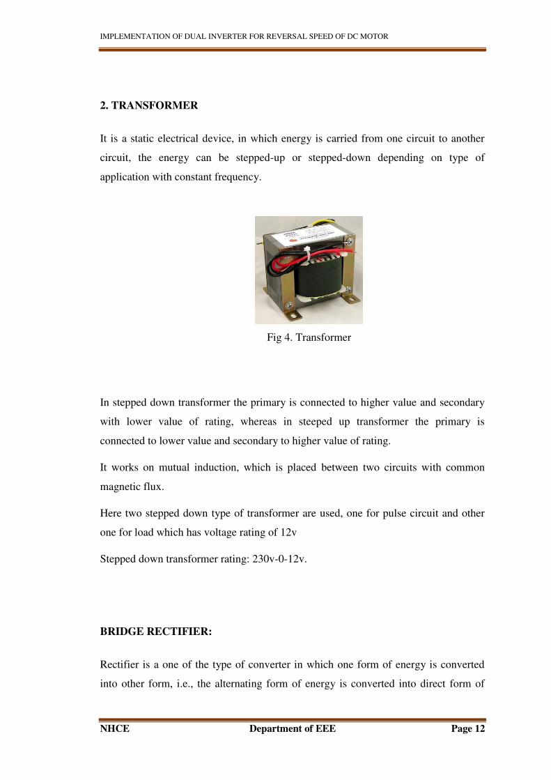
2. TRANSFORMER
It is a static electrical device, in which energy is carried from one circuit to another
circuit, the energy can be stepped-up or stepped-down depending on type of
application with constant frequency.
Fig 4. Transformer
In stepped down transformer the primary is connected to higher value and secondary
with lower value of rating, whereas in steeped up transformer the primary is
connected to lower value and secondary to higher value of rating.
It works on mutual induction, which is placed between two circuits with common
magnetic flux.
Here two stepped down type of transformer are used, one for pulse circuit and other
one for load which has voltage rating of 12v
Stepped down transformer rating: 230v-0-12v.
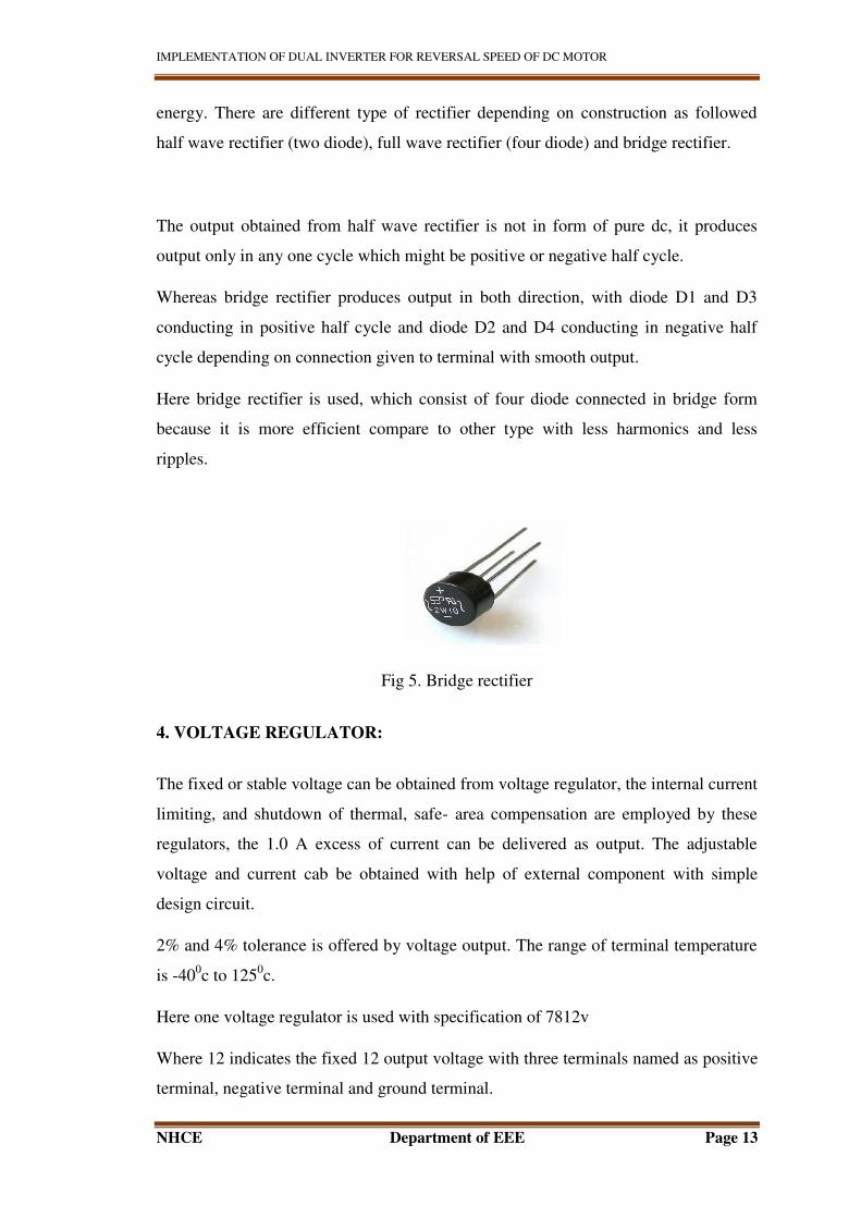
BRIDGE RECTIFIER:
Rectifier is a one of the type of converter in which one form of energy is converted
into other form, i.e., the alternating form of energy is converted into direct form of
IMPLEMENTATION OF DUAL INVERTER FOR REVERSAL SPEED OF DC MOTOR
NHCE Department of EEE Page 13
energy. There are different type of rectifier depending on construction as followed
half wave rectifier (two diode), full wave rectifier (four diode) and bridge rectifier.
The output obtained from half wave rectifier is not in form of pure dc, it produces
output only in any one cycle which might be positive or negative half cycle.
Whereas bridge rectifier produces output in both direction, with diode D1 and D3
conducting in positive half cycle and diode D2 and D4 conducting in negative half
cycle depending on connection given to terminal with smooth output.
Here bridge rectifier is used, which consist of four diode connected in bridge form
because it is more efficient compare to other type with less harmonics and less
ripples.
Fig 5. Bridge rectifier
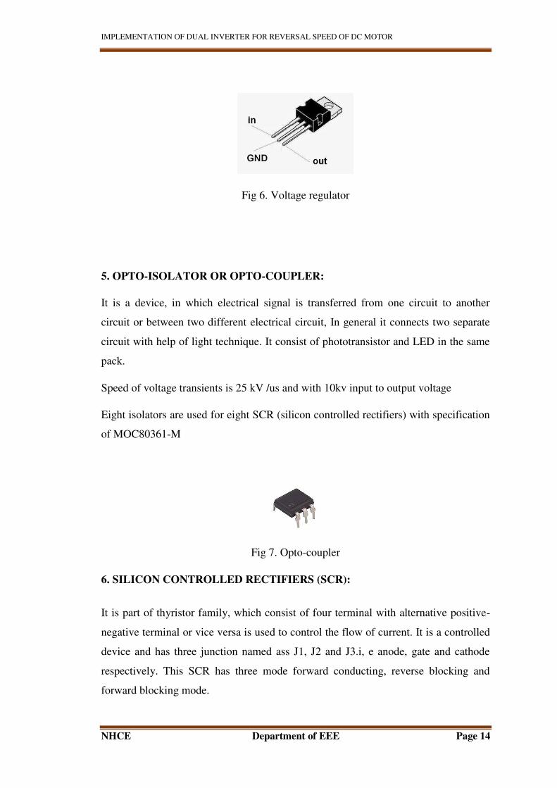
4. VOLTAGE REGULATOR:
The fixed or stable voltage can be obtained from voltage regulator, the internal current
limiting, and shutdown of thermal, safe- area compensation are employed by these
regulators, the 1.0 A excess of current can be delivered as output. The adjustable
voltage and current cab be obtained with help of external component with simple
design circuit.
2% and 4% tolerance is offered by voltage output. The range of terminal temperature
is -400c to 125
0c.
Here one voltage regulator is used with specification of 7812v
Where 12 indicates the fixed 12 output voltage with three terminals named as positive
terminal, negative terminal and ground terminal.
IMPLEMENTATION OF DUAL INVERTER FOR REVERSAL SPEED OF DC MOTOR
NHCE Department of EEE Page 14
Fig 6. Voltage regulator
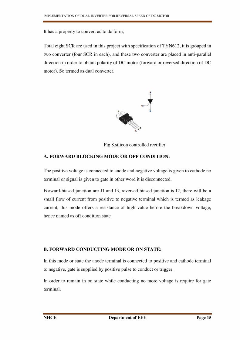
5. OPTO-ISOLATOR OR OPTO-COUPLER:
It is a device, in which electrical signal is transferred from one circuit to another
circuit or between two different electrical circuit, In general it connects two separate
circuit with help of light technique. It consist of phototransistor and LED in the same
pack.
Speed of voltage transients is 25 kV /us and with 10kv input to output voltage
Eight isolators are used for eight SCR (silicon controlled rectifiers) with specification
of MOC80361-M
Fig 7. Opto-coupler
6. SILICON CONTROLLED RECTIFIERS (SCR):
It is part of thyristor family, which consist of four terminal with alternative positive-
negative terminal or vice versa is used to control the flow of current. It is a controlled
device and has three junction named ass J1, J2 and J3.i, e anode, gate and cathode
respectively. This SCR has three mode forward conducting, reverse blocking and
forward blocking mode.
IMPLEMENTATION OF DUAL INVERTER FOR REVERSAL SPEED OF DC MOTOR
NHCE Department of EEE Page 15
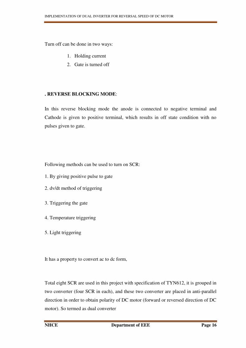
It has a property to convert ac to dc form,
Total eight SCR are used in this project with specification of TYN612, it is grouped in
two converter (four SCR in each), and these two converter are placed in anti-parallel
direction in order to obtain polarity of DC motor (forward or reversed direction of DC
motor). So termed as dual converter.
Fig 8.silicon controlled rectifier
A. FORWARD BLOCKING MODE OR OFF CONDITION:
The positive voltage is connected to anode and negative voltage is given to cathode no
terminal or signal is given to gate in other word it is disconnected.
Forward-biased junction are J1 and J3, reversed biased junction is J2, there will be a
small flow of current from positive to negative terminal which is termed as leakage
current, this mode offers a resistance of high value before the breakdown voltage,
hence named as off condition state
B. FORWARD CONDUCTING MODE OR ON STATE:
In this mode or state the anode terminal is connected to positive and cathode terminal
to negative, gate is supplied by positive pulse to conduct or trigger.
In order to remain in on state while conducting no more voltage is require for gate
terminal.
IMPLEMENTATION OF DUAL INVERTER FOR REVERSAL SPEED OF DC MOTOR
NHCE Department of EEE Page 16
Turn off can be done in two ways:
1. Holding current
2. Gate is turned off
. REVERSE BLOCKING MODE:
In this reverse blocking mode the anode is connected to negative terminal and
Cathode is given to positive terminal, which results in off state condition with no
pulses given to gate.
Following methods can be used to turn on SCR:
1. By giving positive pulse to gate
2. dv/dt method of triggering
3. Triggering the gate
4. Temperature triggering
5. Light triggering
It has a property to convert ac to dc form,
Total eight SCR are used in this project with specification of TYN612, it is grouped in
two converter (four SCR in each), and these two converter are placed in anti-parallel
direction in order to obtain polarity of DC motor (forward or reversed direction of DC
motor). So termed as dual converter
IMPLEMENTATION OF DUAL INVERTER FOR REVERSAL SPEED OF DC MOTOR
NHCE Department of EEE Page 17
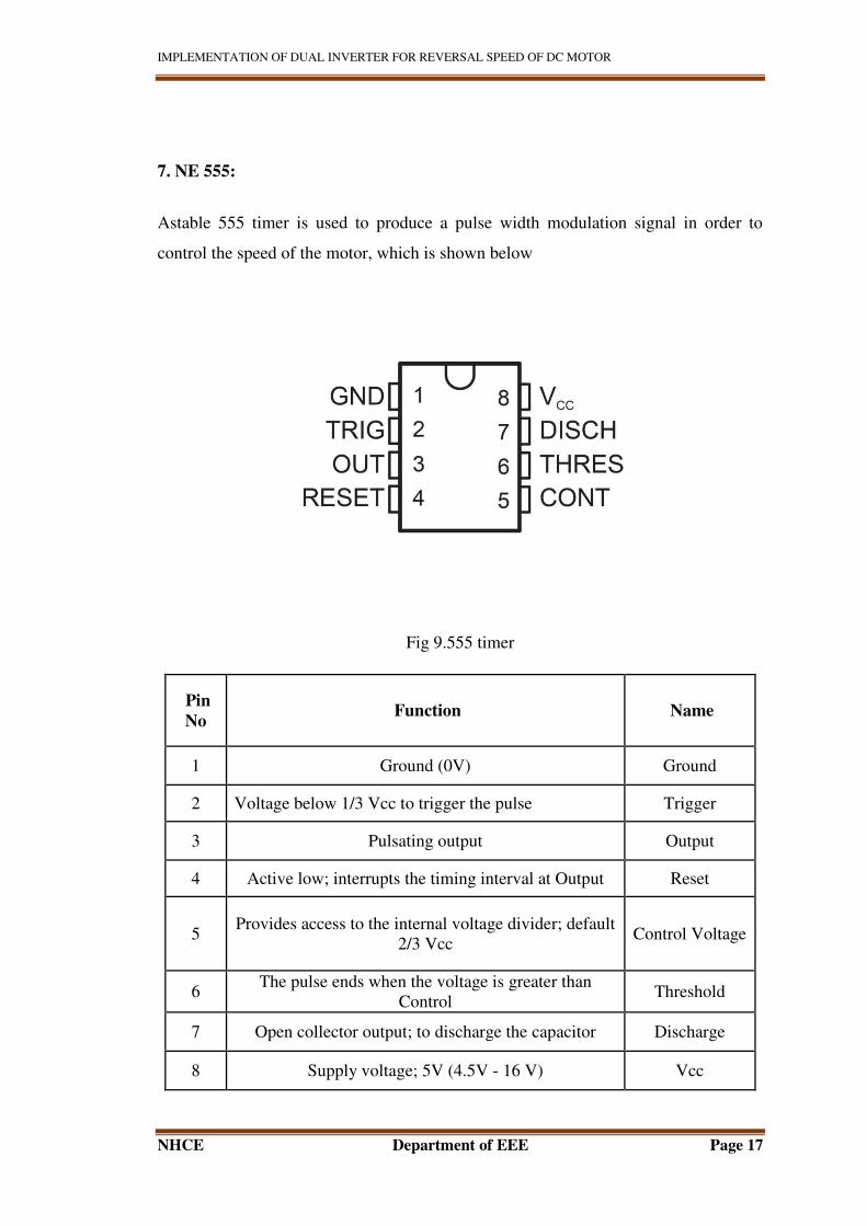
7. NE 555:
Astable 555 timer is used to produce a pulse width modulation signal in order to
control the speed of the motor, which is shown below
Fig 9.555 timer
Pin
No Function Name
1 Ground (0V) Ground
2 Voltage below 1/3 Vcc to trigger the pulse Trigger
3 Pulsating output Output
4 Active low; interrupts the timing interval at Output Reset
5 Provides access to the internal voltage divider; default
2/3 Vcc Control Voltage
6 The pulse ends when the voltage is greater than
Control Threshold
7 Open collector output; to discharge the capacitor Discharge
8 Supply voltage; 5V (4.5V - 16 V) Vcc
IMPLEMENTATION OF DUAL INVERTER FOR REVERSAL SPEED OF DC MOTOR
NHCE Department of EEE Page 18
8. RESISTOR:
It is a passive element which consists of two terminals, which is equivalent to circuit
element, the use of resistor is to reduce the flow of current in the circuit, to level the
signals, as voltage divide etc.
Example: 10K, 20K, 360K etc. so on
9. CAPACITOR:
It is an passive element which is used to store the electrical energy for charging and
discharging purpose depending on circuit, it is also used for filtering, smoothing or
to reduce the harmonics in the circuit. It is also known as filter to remove unwanted
waste signal in order to have smooth output
Ex: .1uf, 47uf etc.
10. ZENER DIODE:
It is a type of diode, but different compare to normal diode, the flow of current from
positive or anode to cathode or negative can be achieved by Zener diode, and it also
allows the flow in reverse direction by reaching the Zener voltage. It is highly doped
positive-negative terminal; the application of Zener diode is wide.
It can also regulate the small amount of voltage.
11. LOAD OR DC MOTOR:
IMPLEMENTATION OF DUAL INVERTER FOR REVERSAL SPEED OF DC MOTOR
NHCE Department of EEE Page 19
Here load is DC motor, Dc motor is a device which takes input as DC electrical
energy and produces output in form of mechanical energy.
Dc motor principle:
The basic working principle of DC motor is left hand Fleming’s rule, The torque can
be produced by a conductor which carry’s current and is placed in magnetic field.it
is also termed as motoring process. The motor rotation can be reversed by reversing
the current direction.
The mechanical output is produced by electric and magnetic fields interaction.
Dc generator and Dc motor are similar in construction and structure, but it is
opposite when it comes to electrically, given by:
The supply voltage E and current I is given at input inside and it produces output
which is in the form of mechanical that is speed w and torque T at output side.
E=NɸPZ/2
The relation between input and output terminal is given by,
KT=KI
E = Kw
The DC motor and DC generator has opposite phenomenon, but by just interchanging
the input and output terminal the motoring or generating action can be obtained.
The speed and polarity of dc motor can be easily achieved by simple method compare
to ac motor. It is used in much industrial application for motoring, speed control and
polarity is required.
CLASSIFICATION OF DC MOTOR:
Depending on armature connection and field winding followed are different type of
DC motor.
1. Shunt DC motor
2. Series DC motor
IMPLEMENTATION OF DUAL INVERTER FOR REVERSAL SPEED OF DC MOTOR
NHCE Department of EEE Page 20
CHAPTER 4
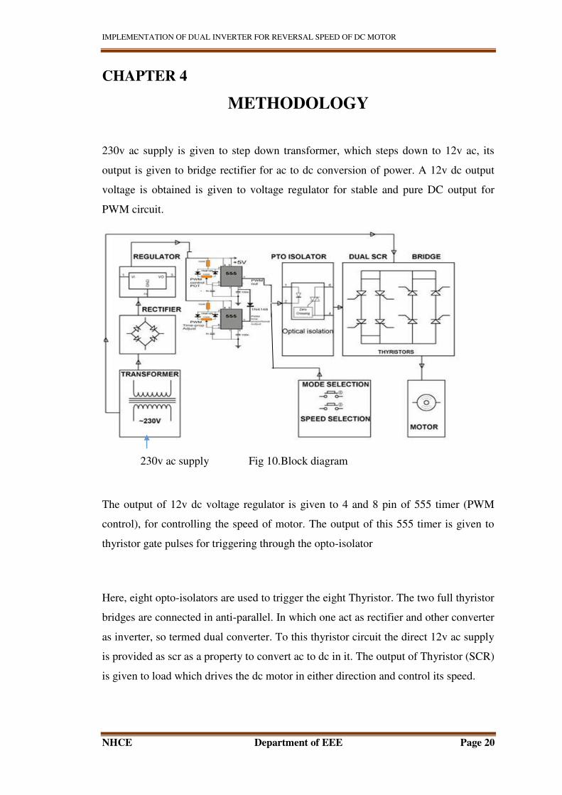
METHODOLOGY
230v ac supply is given to step down transformer, which steps down to 12v ac, its
output is given to bridge rectifier for ac to dc conversion of power. A 12v dc output
voltage is obtained is given to voltage regulator for stable and pure DC output for
PWM circuit.
230v ac supply Fig 10.Block diagram
The output of 12v dc voltage regulator is given to 4 and 8 pin of 555 timer (PWM
control), for controlling the speed of motor. The output of this 555 timer is given to
thyristor gate pulses for triggering through the opto-isolator
Here, eight opto-isolators are used to trigger the eight Thyristor. The two full thyristor
bridges are connected in anti-parallel. In which one act as rectifier and other converter
as inverter, so termed dual converter. To this thyristor circuit the direct 12v ac supply
is provided as scr as a property to convert ac to dc in it. The output of Thyristor (SCR)
is given to load which drives the dc motor in either direction and control its speed.
IMPLEMENTATION OF DUAL INVERTER FOR REVERSAL SPEED OF DC MOTOR
NHCE Department of EEE Page 21
CHAPTER5
WORKING PRINCIPLE
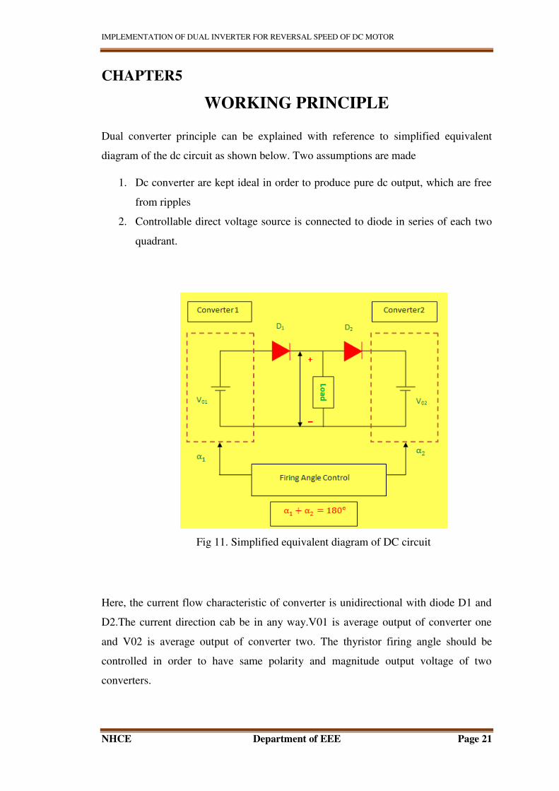
Dual converter principle can be explained with reference to simplified equivalent
diagram of the dc circuit as shown below. Two assumptions are made
1. Dc converter are kept ideal in order to produce pure dc output, which are free
from ripples
2. Controllable direct voltage source is connected to diode in series of each two
quadrant.
Fig 11. Simplified equivalent diagram of DC circuit
Here, the current flow characteristic of converter is unidirectional with diode D1 and
D2.The current direction cab be in any way.V01 is average output of converter one
and V02 is average output of converter two. The thyristor firing angle should be
controlled in order to have same polarity and magnitude output voltage of two
converters.
IMPLEMENTATION OF DUAL INVERTER FOR REVERSAL SPEED OF DC MOTOR
NHCE Department of EEE Page 22
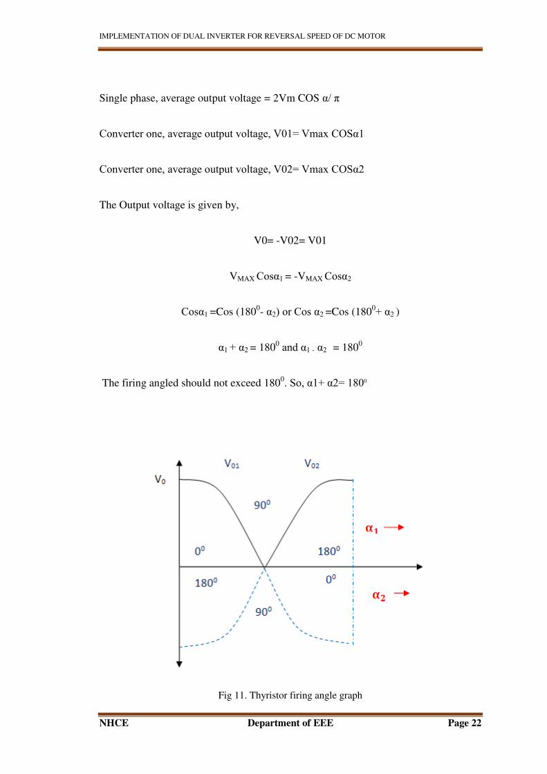
Single phase, average output voltage = 2Vm COS α/ π
Converter one, average output voltage, V01= Vmax COSα1
Converter one, average output voltage, V02= Vmax COSα2
The Output voltage is given by,
V0= -V02= V01
VMAX Cosα1 = -VMAX Cosα2
Cosα1 =Cos (1800- α2) or Cos α2 =Cos (180
0+ α2 )
α1 + α2 = 1800 and α1 - α2 = 180
0
The firing angled should not exceed 1800. So, α1+ α2= 1800
Fig 11. Thyristor firing angle graph

IMPLEMENTATION OF DUAL INVERTER FOR REVERSAL SPEED OF DC MOTOR
NHCE Department of EEE Page 23
There Dual converter can be controlled by following two methods:
(a)Simultaneous or Circulating current method
(b)Non-Simultaneous Circulating current method
IMPLEMENTATION OF DUAL INVERTER FOR REVERSAL SPEED OF DC MOTOR
NHCE Department of EEE Page 24
CHAPTER 6
MODES OF CONTROL FOR THE DUAL
CONVERTER
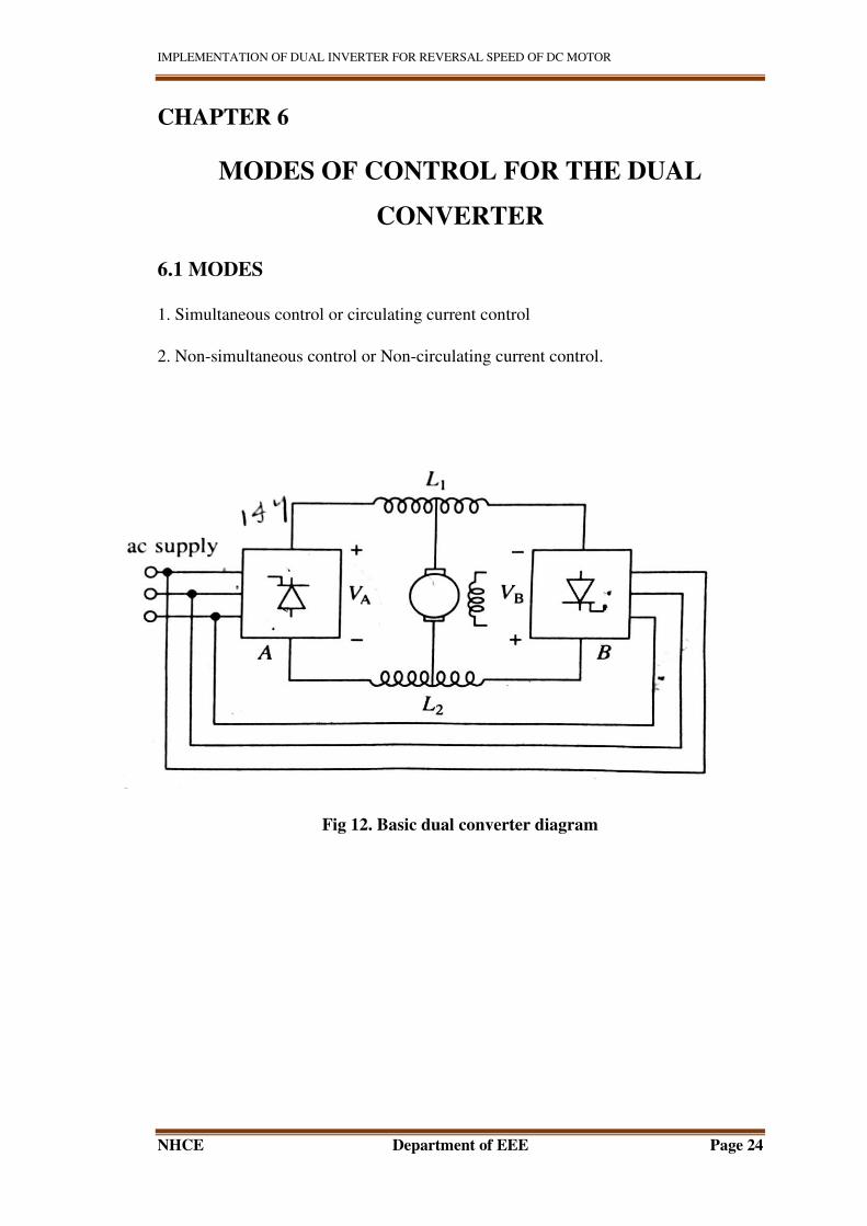
6.1 MODES
1. Simultaneous control or circulating current control
2. Non-simultaneous control or Non-circulating current control.
Fig 12. Basic dual converter diagram
IMPLEMENTATION OF DUAL INVERTER FOR REVERSAL SPEED OF DC MOTOR
NHCE Department of EEE Page 25
6.2. SIMULTANEOUS CONTROL OR CIRCULATING CURRENT
CONTROL:
In this method both the rectifiers are controlled together. The same dc output is
produced across the motor terminal, in which dc circulating current between two
rectifiers is avoided.
Hence,
VA+VB = 0
Cos αA + Cos αB=0
Or αA + αB=1800
If the control of firing angle is done, according to the equation αA + αB=1800, there
will be no circulating current. But due to change in ac instantaneous voltages the
circulating current exists. To limit this circulating current inductors L1 and L2 are
used .the value of inductors is chosen in such a way in order to have 30% of full load
current in case of three phase.
6.2(a). PROCEDURE FOR SPEED REVERSAL:
1. When the motor is operating in First quadrant rectifier A will be rectifying
[0< αA <900] and rectifier will be inverting [90
0< αB <180
0]
2. For speed reversal αA is increased and αB is decreased to satisfy αA +
αB=1800
3. Here the motor back emf exceeds value of VA and VB
4. The armature current shifts to rectifier B and operates in second quadrant
5. Using current control loop, the value of αB is adjusted continuously.
IMPLEMENTATION OF DUAL INVERTER FOR REVERSAL SPEED OF DC MOTOR
NHCE Department of EEE Page 26
6.2(b). DISADVANTAGES
The weight, volume, cost and reversal time is increased with inductor L1and L2
The losses are increased due to circulating current
6.3. NON-SIMULTANEOUS CONTROL OR NON-CIRCULATING
CURRENT CONTROL METHOD
Here any one rectifier is operated at a time .no need of inductors L1 and L2 because
there is no circulating current. This eliminates weight and volume associated with
conductor and also eliminates losses associated with circulating current. As drive
operates in discontinuous conduction this method is not applicable for light loads.
6.3(a). THE PROCEDURE FOR SPEED REVERSAL:
1. When operating in quadrant one rectifier A will be supplying the motor and
rectifier B will not be operating.
2. The firing angle of rectifier A is set to highest value
3. The rectifier act as an inverter and forces armature current to zero
4. After this zero current is sensed pulses are stopped for rectifier A
5. Now the pulses are shifted from rectifier A to rectifier B
6. αB is set to highest value and using current controller αB is set as required
6.3(b). ADVANTAGES
1. Reversal time is decreased because no inductors L1 and L2
2. Response is faster than simultaneous control
Here, in this project we use Non-Simultaneous mode of control because of above
advantages.
IMPLEMENTATION OF DUAL INVERTER FOR REVERSAL SPEED OF DC MOTOR
NHCE Department of EEE Page 27
CHAPTER 7
FOUR QUADRANT OPERATIONS
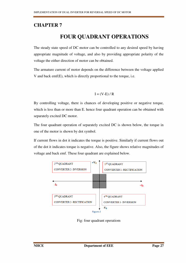
The steady state speed of DC motor can be controlled to any desired speed by having
appropriate magnitude of voltage, and also by providing appropriate polarity of the
voltage the either direction of motor can be obtained.
The armature current of motor depends on the difference between the voltage applied
V and back emf(E), which is directly proportional to the torque, i.e.
I = (V-E) / R
By controlling voltage, there is chances of developing positive or negative torque,
which is less than or more than E. hence four quadrant operation can be obtained with
separately excited DC motor.
The four quadrant operation of separately excited DC is shown below, the torque in
one of the motor is shown by dot symbol.
If current flows in dot it indicates the torque is positive. Similarly if current flows out
of the dot it indicates torque is negative. Also, the figure shows relative magnitudes of
voltage and back emf. These four quadrant are explained below.
Fig: four quadrant operatiom
IMPLEMENTATION OF DUAL INVERTER FOR REVERSAL SPEED OF DC MOTOR
NHCE Department of EEE Page 28
7.1. FORWARD MOTORING
The positive current flow into the motor, because voltage applied is positive and
greater than the back emf E of the motor.As both applied voltage and current is
positive, the output power will be positive. In this quadrant speed and torque will also
be positive, hence rotation of motor will be in forward direction (forward motoring
mode).
7.2. FORWARD BRAKING
In this mode, the induced emf remains positive and motor runs in forward direction.
But the value of supplied voltage suddenly falls to a value which is less than back E.
Hence direction of current (torque) is reversed. The energy flow is also reversed due
to negative torque.
As direction of load torque and motor torque is reversed, the speed of motor will be
reduced due to combined effect and hence E falls back value below applied voltage
Hence, the motor settles down to I quadrant as voltage and current becomes positive
the flow power from load to source is known is regenerating braking.
This quadrant is an example for regenerative braking.
7.3. REVERSE MOTORING
In this mode both current and voltage are negative, which results in positive power
that is the motor takes energy from source and gives to load
The rotation of motor is reversed due to reverse polarity (the rotation of motor will be
in a counter clockwise direction
IMPLEMENTATION OF DUAL INVERTER FOR REVERSAL SPEED OF DC MOTOR
NHCE Department of EEE Page 29
It is similar to I quadrant, but direction of motor is reversed in this mode. The desired
speed in reverse direction is decided by magnitude of voltage of motor
7.4. REVERSE REGENERATIVE BRAKING
In this quadrant or mode of operation the voltage of motor continues to be negative
with positive armature current
This mode is as same as II quadrant operation, the regenerative takes place in which
back emf E is greater than the negative supply voltage.
Due to reverse direction the speed of motor will be reduced, the load torque is
opposed by torque which is positive.
To stop the motor rapidly and in case of plugging this mode can be mostly used.
IMPLEMENTATION OF DUAL INVERTER FOR REVERSAL SPEED OF DC MOTOR
NHCE Department of EEE Page 30
CHAPTER 8
SPEED CONTROL OF DC MOTOR
Need of speed control.
The speed control of dc motor is required for application such as traction, mills,
cranes, air compressor, hair drier, sewing machine, arc welding etc. both speed
regulation and speed control has different concept, the speed control method is natural
process in which the speed is controlled by load change. It can automatically or
manually depending on type of application. One of the best application of dc motor is
the speed can be controlled easily.
Dc motor types are: series, shunt and compound.in which speed can be controlled
easily.
Dc motor speed can be controlled in two ways:
1. By controlling armature voltage
2. By controlling field voltage
Dc series motor speed control:
There are two methods in dc motor to control speed one is by adjusting armature
voltage and other one by field adjustment.
8.1. Armature voltage control:
Adjusting dc series armature voltage:
In this method the armature voltage is adjusted by any one this following method:
1. By changing the resistance value:
The source of motor is directly connected in series with resistance i.e. controlling
resistance as shown in below diagram,
IMPLEMENTATION OF DUAL INVERTER FOR REVERSAL SPEED OF DC MOTOR
NHCE Department of EEE Page 31
The speed can be reduced for large duration of time in this method with less power
loss or loss are neglected.
Advantage:
Economical
Simple method
Application:
Driving cranes, hoists, trains etc.
DC shunt armature speed control:
It is a combination of parallel armature rheostat and series armature. Rheostat is
involved for speed control. By varying series rheostat R1 the armature can be adjusted
and the resistance R2 is used to adjust exciting Current.
Advantage:
Wide range of speed control is obtained in this advantage
Disadvantage:
Not economical, more power loss
8.2. Field Control of DC Series Motor:
The speed of DC motor can be controlled by this method by any one of the following
ways –
I. Field Diverter Method This method uses a diverter. Here the field flux can be
reduced by shunting a portion of motor current around the series field. Lesser the
diverter resistance less is the field current, less flux therefore more speed. This
method gives speed above normal and the method is used in electric drives in which
speed should rise sharply as soon as load is decreased.
IMPLEMENTATION OF DUAL INVERTER FOR REVERSAL SPEED OF DC MOTOR
NHCE Department of EEE Page 32
II.Field Rheostat Control of DC Shunt Motor.
In this method, speed variation is accomplished by means of a variable resistance
inserted in series with the shunt field. An increase in controlling resistances reduces
the field current with a reduction in flux and an increase in speed. This method of
speed control is independent of load on the motor. Power wasted in controlling
resistance is very less as field current is a small value. This method of speed control is
also used in DC compound motor.
Limitations of this Method of Speed Control
o Creeping speeds cannot be obtained.
o Top speeds only obtained at reduced torque.
o The speed is maximum at minimum value of flux, which is governed by the
demagnetizing effect of armature reaction on the field.
IMPLEMENTATION OF DUAL INVERTER FOR REVERSAL SPEED OF DC MOTOR
NHCE Department of EEE Page 33
CHAPTER 9
PULSE WIDTH MODUALTION
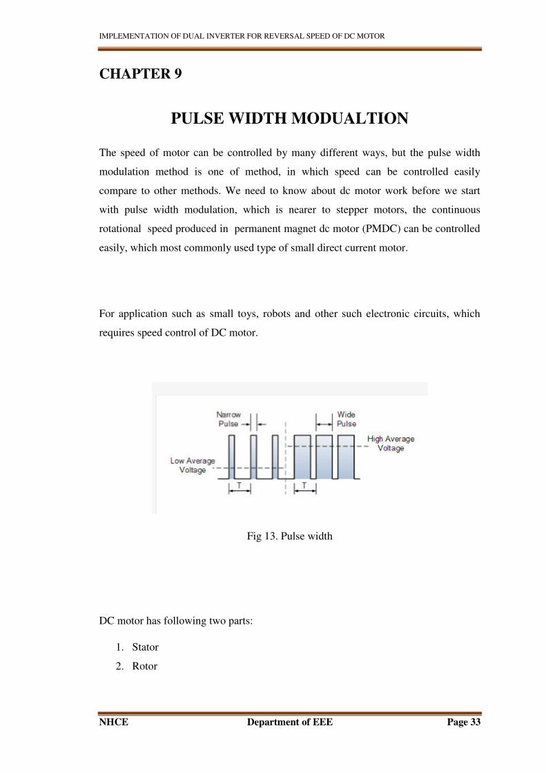
The speed of motor can be controlled by many different ways, but the pulse width
modulation method is one of method, in which speed can be controlled easily
compare to other methods. We need to know about dc motor work before we start
with pulse width modulation, which is nearer to stepper motors, the continuous
rotational speed produced in permanent magnet dc motor (PMDC) can be controlled
easily, which most commonly used type of small direct current motor.
For application such as small toys, robots and other such electronic circuits, which
requires speed control of DC motor.
Fig 13. Pulse width
DC motor has following two parts:
1. Stator
2. Rotor
IMPLEMENTATION OF DUAL INVERTER FOR REVERSAL SPEED OF DC MOTOR
NHCE Department of EEE Page 34
1) Stator:
Stator is the outer part of the DC motor which is stationary. For small
applications of the motor, it consists of two permanent fixed magnets which produces
uniform and stationary magnetic flux inside the motor which is termed as “permanent-
magnet direct current” (PMDC) motors.
2) Rotor:
The inner part which rotates is called as the rotor. It is also known as Armature
of the DC motor. The individual electrical coils of the motor armature are connected
together around its metallic body in circular configuration to produce alternative north
and South Pole
This pulse width modulation method has advantage in which power loss is less while
speed of motor is controlled. The motor is always at full strength as the amplitude of
motor remains constant. Hence the rotation of the motor reduces slowly without it
stalling
Astable 555 timer is used to produce a pulse width modulation signal in order to
control the speed of the motor, which is shown below,
IMPLEMENTATION OF DUAL INVERTER FOR REVERSAL SPEED OF DC MOTOR
NHCE Department of EEE Page 35
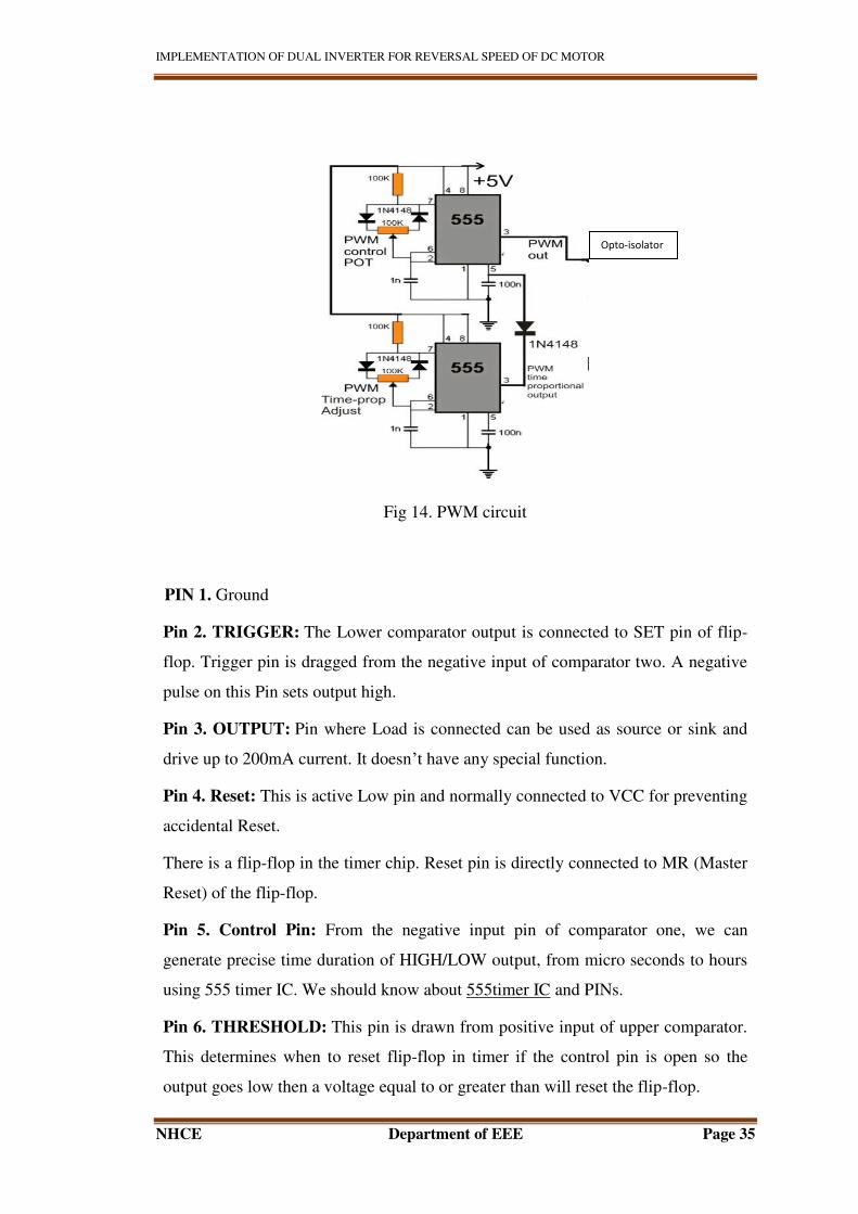
Fig 14. PWM circuit
PIN 1. Ground
Pin 2. TRIGGER: The Lower comparator output is connected to SET pin of flip-
flop. Trigger pin is dragged from the negative input of comparator two. A negative
pulse on this Pin sets output high.
Pin 3. OUTPUT: Pin where Load is connected can be used as source or sink and
drive up to 200mA current. It doesn’t have any special function.
Pin 4. Reset: This is active Low pin and normally connected to VCC for preventing
accidental Reset.
There is a flip-flop in the timer chip. Reset pin is directly connected to MR (Master
Reset) of the flip-flop.
Pin 5. Control Pin: From the negative input pin of comparator one, we can
generate precise time duration of HIGH/LOW output, from micro seconds to hours
using 555 timer IC. We should know about 555timer IC and PINs.
Pin 6. THRESHOLD: This pin is drawn from positive input of upper comparator.
This determines when to reset flip-flop in timer if the control pin is open so the
output goes low then a voltage equal to or greater than will reset the flip-flop.
Opto-isolator
IMPLEMENTATION OF DUAL INVERTER FOR REVERSAL SPEED OF DC MOTOR
NHCE Department of EEE Page 36
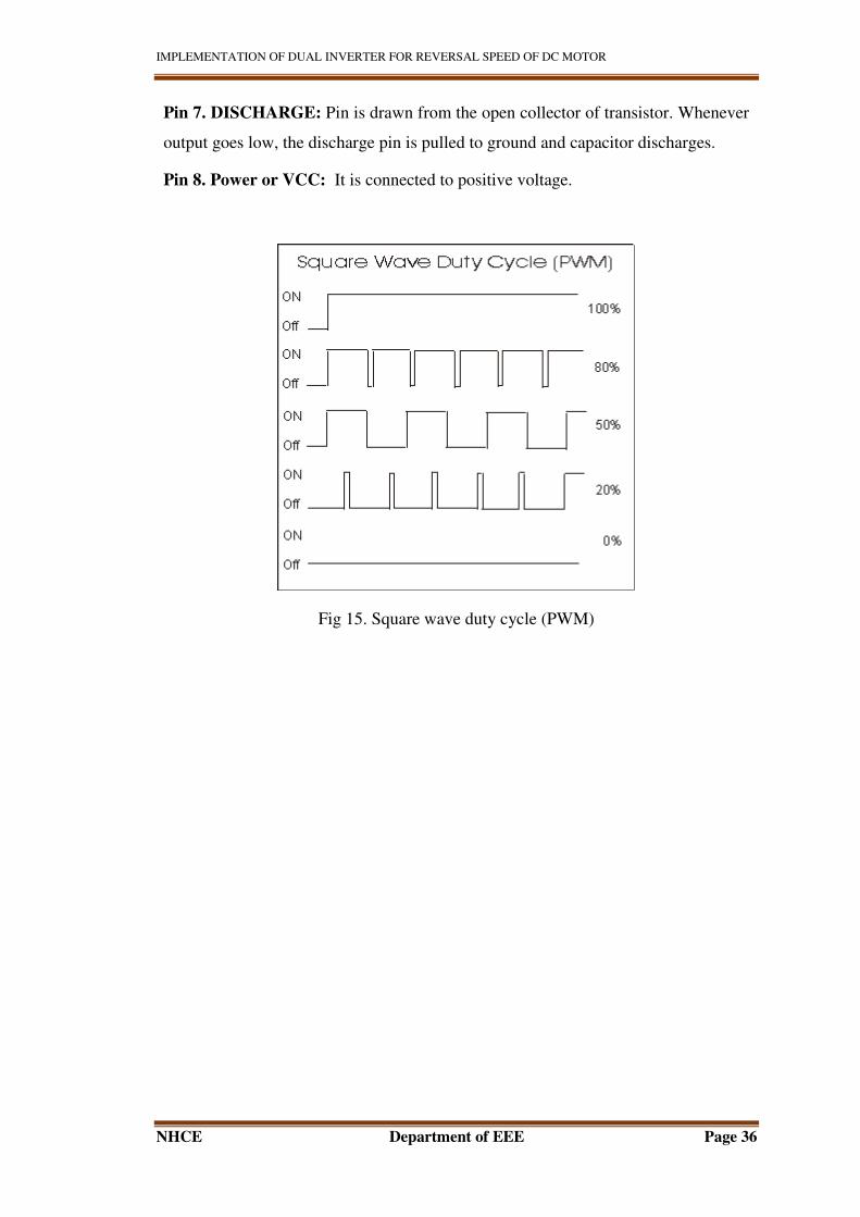
Pin 7. DISCHARGE: Pin is drawn from the open collector of transistor. Whenever
output goes low, the discharge pin is pulled to ground and capacitor discharges.
Pin 8. Power or VCC: It is connected to positive voltage.
Fig 15. Square wave duty cycle (PWM)
IMPLEMENTATION OF DUAL INVERTER FOR REVERSAL SPEED OF DC MOTOR
NHCE Department of EEE Page 37
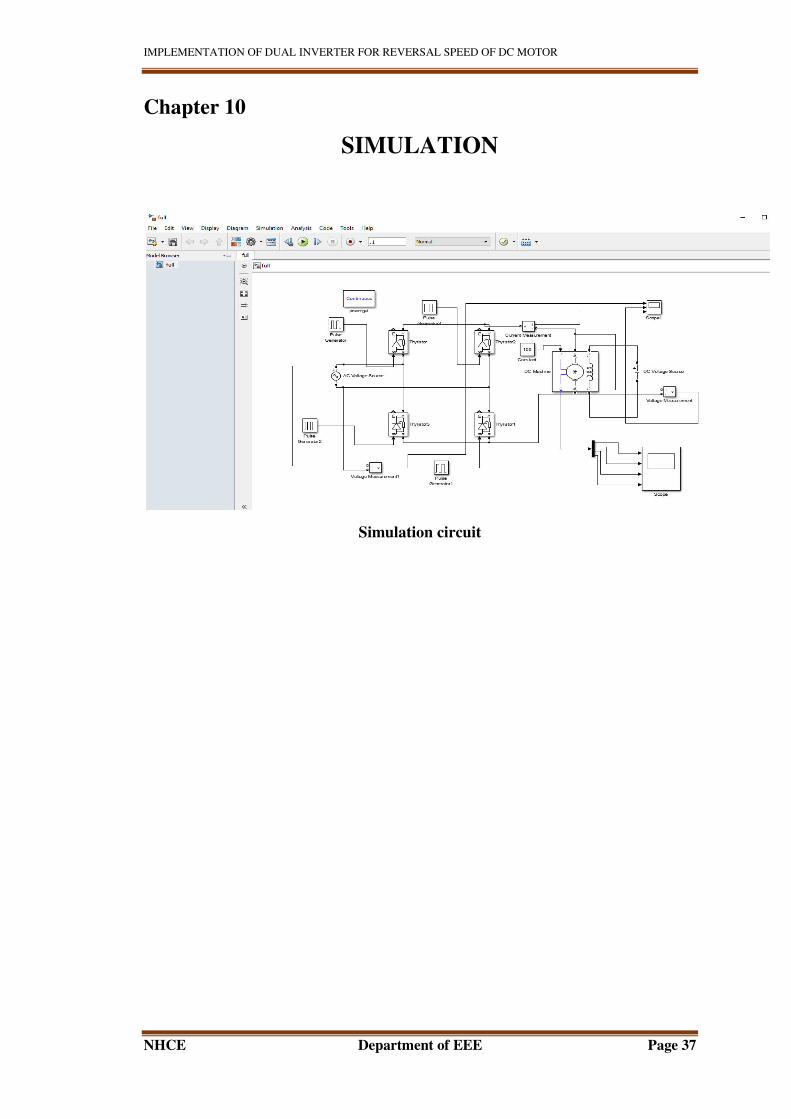
Chapter 10
SIMULATION
Simulation circuit
IMPLEMENTATION OF DUAL INVERTER FOR REVERSAL SPEED OF DC MOTOR
NHCE Department of EEE Page 38
CHAPTER 11
APPLICATION
1. PAPER INDUSTRY.
The drive frequency transformation machine section paper production is a continuous
process, so continuous and orderly control has become a constraint finished paper
quality and yield of the production line bottlenecks. DC speed control system in the
history of the paper machine plays an important role At present paper mill branch
transmission equipment, previously used SCR DC speed mode, because of slip rings
and carbon brushes cause reliability and accuracy is not high, resulting in a
mechanical machine backward, the maximum speed is only 200m / min or so, it is
difficult compared with overseas 1000m / min high-speed machine.
Frequency transformation of paper machine drive has very good results, such as
improved paper products, increase production capacity from the process, reduce
energy consumption and extend the shutdown inspection cycle. For the production
process characteristics of the sheet changing needs of variable frequency drive
machine can be adjusted within a certain range to ensure the speed, and the speed of
each segment can be adjusted individually.
2. MEDICAL ANALYZERS:
Medical analysers’ are multifunction machines that test human bodily fluids such as
blood and urine. Fluid samples within the analyzers move from station to station for
various tests. Generally, medical analyzers are totally enclosed. The temperature
within them will rise to well above ambient temperature during periods of peak
operation. Medical analyzers are designed to test thousands of samples annually and
to run a minimum of 8 hr. daily.
IMPLEMENTATION OF DUAL INVERTER FOR REVERSAL SPEED OF DC MOTOR
NHCE Department of EEE Page 39
DC motor, are the most common type of motor in medical analyzers today. BLDC
motor has a typical pole count of six. For example, step motors rarely exceed 1,000
rpm because of their high pole count. Yet BLDC motors can easily reach top speeds
of 5,000 rpm or more.
Machines with higher throughput need motors that rotate at speeds above the
capability of stepper motors. BLDC motors fill that need for medical analyzers
because they combine high-speed operation, high heat-transfer efficiency, and long
life.
3. TRACTION
The use of DC series motor for traction because of its ability to produce high torque at
low speeds that is what we need in traction.
4. for speed control of DC motor
5. for generating braking
6. in power processing system
IMPLEMENTATION OF DUAL INVERTER FOR REVERSAL SPEED OF DC MOTOR
NHCE Department of EEE Page 40
CHAPTER12
ADVANTAGES
1. Thyristor:
Motor speed control using power electronics based drives is obviously much
better than mechanical drives and valve-based converters in terms of efficiency
improvement. Thyristor is Silicon controlled rectifier. It has high power rating and
is robust and is usually fit for phase-angle control. It can be switched On/Off to
control the voltage supply to motor used in flux-based speed control methods or
can change the frequency of supply to an AC motor to control speed accordingly.
However it does not have very high switching frequency of order of 100 KHz. It
can be turned ON by gate control, the turning off requires support from the supply
side (line commutation) which distorts the supply power factor or requires extra
circuitry for forced-commutation. Very high frequency devices like power
MOSFETs and IGBTs are better suited for industrial scale motor speed control,
SCR offering the only advantage of cost for same frequency and power
application.
2. Pulsewidthmodulation:
The use of pulse width modulation to control a small motor has the advantage in
that the power loss in the switching transistor is small because the transistor is
either fully “ON” or fully “OFF”. As a result the switching transistor has a much
reduced power dissipation giving it a linear type of control which results in better
speed stability. Also the amplitude of the motor voltage remains constant so the
motor is always at full strength. The result is that the motor can be rotated much
more slowly without it stalling.
IMPLEMENTATION OF DUAL INVERTER FOR REVERSAL SPEED OF DC MOTOR
NHCE Department of EEE Page 41
CHAPTER 13
Future scope
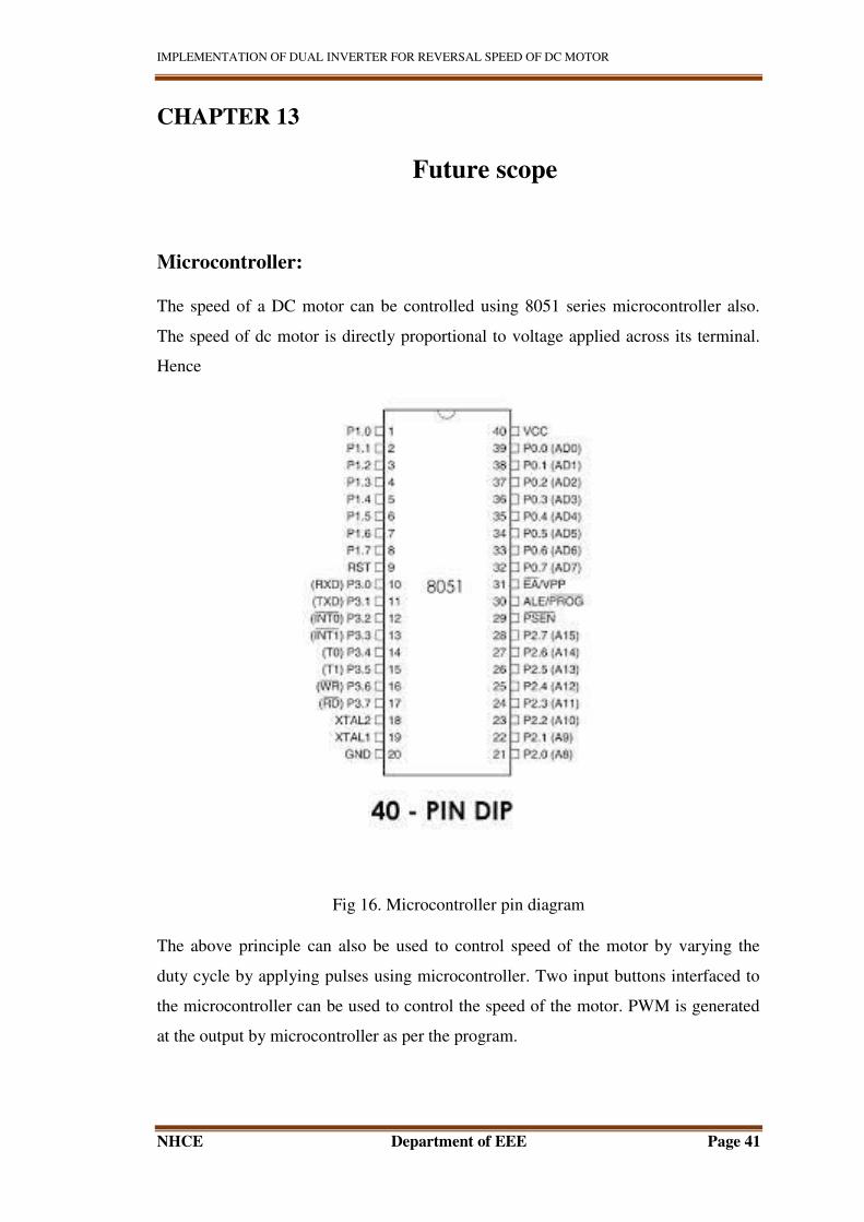
Microcontroller:
The speed of a DC motor can be controlled using 8051 series microcontroller also.
The speed of dc motor is directly proportional to voltage applied across its terminal.
Hence
Fig 16. Microcontroller pin diagram
The above principle can also be used to control speed of the motor by varying the
duty cycle by applying pulses using microcontroller. Two input buttons interfaced to
the microcontroller can be used to control the speed of the motor. PWM is generated
at the output by microcontroller as per the program.

IMPLEMENTATION OF DUAL INVERTER FOR REVERSAL SPEED OF DC MOTOR
NHCE Department of EEE Page 42
The average voltage given or the average current flowing through the motor will
change depending on the duty cycle (on and off time of the pulses), so the speed of
the motor will change. A motor drive IC is interfaced to the microcontroller for
receiving PWM signals and delivering desired outputs for speed control system of a
small dc motor.
Further the project can also be enhanced by IGBT to achieve speed control for higher
capacity industrial motors.
IMPLEMENTATION OF DUAL INVERTER FOR REVERSAL SPEED OF DC MOTOR
NHCE Department of EEE Page 43
CHAPTER 14
CONCLUSION
This paper discussed the detailed study of DC machine speed control using dual
converter in both the direction(forward and reverse) and in both the mode of
operation(generating and motoring). Dual converters are used for four-quadrant
operation of DC drive. In non-circulating mode of operation there is no need of
inductors and power losses are less. So the speed reversal is very quick and smooth.
The results of non-circulating current mode of operation are shown in this project.
IMPLEMENTATION OF DUAL INVERTER FOR REVERSAL SPEED OF DC MOTOR
NHCE Department of EEE Page 44
CHAPTER 15
REFERENCE
[1] S. J. Chapman, Electric Machinery Fundamentals, New York: WCB/McGraw-
Hill, 1998.
[2] D. A. staton, M. I. McGilp and T. J. E. Miller, “DC machine teaching
experiment,” in proceedings of the European Power Electronics Association EPE,
Brighton, pp. 35 – 40, 1993
[3] M. Nedeljkovic and Z. Stojiljkovic, “Fast current control for thyristor rectifiers,”
IEE Proceedings- Electr. Power Appl., Vol. 150, No. 6, pp. 636- 638, Nov. 2003.
[4] Alfio Consoli, Mario Cacciato, Antonio Testa and Francesco Gennaro, “Single
Chip Integration for Motor Drive Converters with Power Factor Capability,” IEEE
Transactions on Power Electronics, Vol. 19, No. 6, pp. 1372-1379, Nov. 20
[5] Wai Phyo Anug, “Analysis on Modelling and Simulink of DC Motor and its
Driving System Used for Wheeled Mobile Robot,” World Academy of Science,
Engineering and Technology 32, pp. 299-306, 2007
[6] Sch. of Electr, Electron. & Syst. Eng., Univ. Coll. of Cardiff, UK (Techniques for
Testing and Measuring Digital Systems, IEE Colloquium)
[7]Gopal K. Dubey, “Fundamental of electrical Drives", Narosa Publication 2009.
[8]. I.J. Nagrath & M. Gopal, "Control Systems Engineering," New Age Publication
2003.
[9]. Power Electronics: P .S.Bimbhra
[10]. Mohan, Ned, “Electric Drives – An Integrative Approach,” MNPERE, 2003. 7.
Control of electrical drives:

IMPLEMENTATION OF DUAL INVERTER FOR REVERSAL SPEED OF DC MOTOR
NHCE Department of EEE Page 45
Related Documents