Abstract—The Controller Output Error Method (COEM) is introduced and applied to the design of an adaptive fuzzy controller for a PUMA robot. The method employs a gradient decent algorithm to minimize a cost function which is based on the error at the controller output. The cost function is minimized by adapting some or all of the parameters of the fuzzy controller. The paper also describes the replacement of a controller for a PUMA 512 robot with a newly designed PC based (open architecture) controller employing COEM. The original structure of the PUMA robot is retained. The hardware of the new controller includes in-house designed parts as: PWM amplifiers; digital and analog controllers; I/O cards; signal conditioner cards; and 16 bits A/D and D/A boards. An Intel Pentium IV industrial computer is used as the central controller. The control software has been implemented using VC++ programming language. The trajectory tracking performance of all the six joints was tested at varying velocities. The experimental results showed that it is feasible to implement the suggested open architecture platform for PUMA 500 Series robots through software routines running on a PC. Index Terms—PUMA robot, Adaptive fuzzy control, Pulse width modulation (PWM) amplifier, Graphical user Interface (GUI), Controller output error method (COEM). I. INTRODUCTION Robots form an essential part of mechatronics and Computer Integrated Manufacturing (CIM) systems. Robots are generally controlled by dedicated controllers. As upgrades become costly and interfacing becomes complex due to hardware and software conflicts, the flexibility of the robotic manipulators is reduced. Dedicated hardware and proprietary software which normally allows only high level programming by the users are costly and difficult to understand. Since the early years of 1980’s many projects have been carried out to develop an open architecture controller such as NGC[1], GISC[2], ROBLINE[3] and so on which try to solve the problem of realization of an open architecture controller, and several prototype systems have been developed. However, they are not widely accepted due to the overly restrictive definitions and special standards. Manuscript received January 07, 2008. This work was supported in part by the Simulation & Machine Control Lab, College of Automation Engineering, Nanjing University of Aeronautics & Astronautics. M. Farooq is with the Simulation & Machine Control Lab, College of Automation Engineering, Nanjing University of Aeronautics & Astronautics, 210016, PR China (phone: +86-25-84892310; fax: +86-25-84498069; e-mail: [email protected]) Dao-Bo Wang is with the Simulation & Machine Control Lab, College of Automation Engineering, Nanjing University of Aeronautics & Astronautics, 210016, PR China (e-mail: [email protected]). . The Unimate PUMA 500 series Robots mainly uses DEC LSI 11 processor running VAL robot control software[4]. Methods of bypassing VAL are discussed in literature, including Unimation technical reports[5]. However, most of these procedures have been confined to replacing the LSI 11 with another DEC computer, leaving peripheral hardware intact. A well- refined open structure architecture for industrial robot is discussed in [6]. However; it is mainly based on Common Object Request Broker Architecture (COBRA), leaving scope to simplify the hardware and software work. A hardware retrofit for Puma 560 robot is discussed in [7] but still it relies on special-purpose TRC041 cards installed on the backplane of Mark II controller. The shift towards the personal computer open architecture robot controller and the impact of using these newer controllers for system integration is discussed in [8]. In fact; it is far more cost effective to develop new hardware using less specific interfaces. An improved PC-based design for Puma robot was presented in [9] but this hardware configuration purely depends on in-house built designs. In our paper a flexible, modular hardware is developed for the puma robot, incorporating a personal computer, in-house as well as specialized hardware. Some technical problems in the previous design for velocity test profile of joints1, 2 and 4 have also been addressed. The joints position tracking error at high velocities is also minimized in our design. In this paper, an adaptive fuzzy control design is developed for robot trajectory tracking control. The controller output error method (COEM) is introduced in proposed design, which can be used for the on-line tuning of parameters of a fuzzy controller. This method can be used with any fuzzy controller design; the only requirement is that controller must be stable before the commencement of on-line tuning. Thus, at first, any fuzzy rule-based model and any inference mechanism can be employed to parameterize and initialize controller of the system, and then COEM is applied subsequently to tune parameters of fuzzy controller for purpose of achieving better performance Although the method has already been discussed by few authors 10, 11 but its implementation for a PUMA robot using an open architecture platform was not studied so far. The authors employ the adaptive fuzzy control using COEM method as a control strategy to implement the open architecture design for PUMA 560 robot. II. ORIGINAL PUMA UNIMATE 500 The Unimation Mark II is an industrial robot controller as shown as in Fig.1. It consists of mainly a DEC LS1 serial Implementation of a New PC based Controller for a PUMA Robot based on COEM M. Farooq M, Member IAENG. Dao Bo Wang IAENG International Journal of Computer Science, 35:2, IJCS_35_2_01 ______________________________________________________________________________________ (Advance online publication: 20 May 2008)

Welcome message from author
This document is posted to help you gain knowledge. Please leave a comment to let me know what you think about it! Share it to your friends and learn new things together.
Transcript

Abstract—The Controller Output Error Method (COEM) is
introduced and applied to the design of an adaptive fuzzy
controller for a PUMA robot. The method employs a gradient
decent algorithm to minimize a cost function which is based on
the error at the controller output. The cost function is minimized
by adapting some or all of the parameters of the fuzzy controller.
The paper also describes the replacement of a controller for a
PUMA 512 robot with a newly designed PC based (open
architecture) controller employing COEM. The original
structure of the PUMA robot is retained. The hardware of the
new controller includes in-house designed parts as: PWM
amplifiers; digital and analog controllers; I/O cards; signal
conditioner cards; and 16 bits A/D and D/A boards. An Intel
Pentium IV industrial computer is used as the central controller.
The control software has been implemented using VC++
programming language. The trajectory tracking performance of
all the six joints was tested at varying velocities. The
experimental results showed that it is feasible to implement the
suggested open architecture platform for PUMA 500 Series
robots through software routines running on a PC.
Index Terms—PUMA robot, Adaptive fuzzy control, Pulse
width modulation (PWM) amplifier, Graphical user Interface
(GUI), Controller output error method (COEM).
I. INTRODUCTION
Robots form an essential part of mechatronics and Computer
Integrated Manufacturing (CIM) systems. Robots are
generally controlled by dedicated controllers. As upgrades
become costly and interfacing becomes complex due to
hardware and software conflicts, the flexibility of the robotic
manipulators is reduced. Dedicated hardware and proprietary
software which normally allows only high level programming
by the users are costly and difficult to understand.
Since the early years of 1980’s many projects have been
carried out to develop an open architecture controller such as
NGC[1], GISC[2], ROBLINE[3] and so on which try to solve
the problem of realization of an open architecture controller,
and several prototype systems have been developed.
However, they are not widely accepted due to the overly
restrictive definitions and special standards.
Manuscript received January 07, 2008. This work was supported in part
by the Simulation & Machine Control Lab, College of Automation
Engineering, Nanjing University of Aeronautics & Astronautics.
M. Farooq is with the Simulation & Machine Control Lab, College of
Automation Engineering, Nanjing University of Aeronautics &
Astronautics, 210016, PR China (phone: +86-25-84892310; fax:
+86-25-84498069; e-mail: [email protected])
Dao-Bo Wang is with the Simulation & Machine Control Lab, College of
Automation Engineering, Nanjing University of Aeronautics &
Astronautics, 210016, PR China (e-mail: [email protected]).
.
The Unimate PUMA 500 series Robots mainly uses DEC LSI
11 processor running VAL robot control software[4].
Methods of bypassing VAL are discussed in literature,
including Unimation technical reports[5]. However, most of
these procedures have been confined to replacing the LSI 11
with another DEC computer, leaving peripheral hardware
intact. A well- refined open structure architecture for
industrial robot is discussed in [6]. However; it is mainly
based on Common Object Request Broker Architecture
(COBRA), leaving scope to simplify the hardware and
software work. A hardware retrofit for Puma 560 robot is
discussed in [7] but still it relies on special-purpose TRC041
cards installed on the backplane of Mark II controller.
The shift towards the personal computer open architecture
robot controller and the impact of using these newer
controllers for system integration is discussed in [8]. In fact; it
is far more cost effective to develop new hardware using less
specific interfaces. An improved PC-based design for Puma
robot was presented in [9] but this hardware configuration
purely depends on in-house built designs. In our paper a
flexible, modular hardware is developed for the puma robot,
incorporating a personal computer, in-house as well as
specialized hardware. Some technical problems in the
previous design for velocity test profile of joints1, 2 and 4
have also been addressed. The joints position tracking error at
high velocities is also minimized in our design.
In this paper, an adaptive fuzzy control design is developed
for robot trajectory tracking control. The controller output
error method (COEM) is introduced in proposed design,
which can be used for the on-line tuning of parameters of a
fuzzy controller. This method can be used with any fuzzy
controller design; the only requirement is that controller must
be stable before the commencement of on-line tuning. Thus,
at first, any fuzzy rule-based model and any inference
mechanism can be employed to parameterize and initialize
controller of the system, and then COEM is applied
subsequently to tune parameters of fuzzy controller for
purpose of achieving better performance Although the
method has already been discussed by few authors10, 11
but its
implementation for a PUMA robot using an open architecture
platform was not studied so far. The authors employ the
adaptive fuzzy control using COEM method as a control
strategy to implement the open architecture design for PUMA
560 robot.
II. ORIGINAL PUMA UNIMATE 500
The Unimation Mark II is an industrial robot controller as
shown as in Fig.1. It consists of mainly a DEC LS1 serial
Implementation of a New PC based Controller
for a PUMA Robot based on COEM
M. Farooq M, Member IAENG. Dao Bo Wang
IAENG International Journal of Computer Science, 35:2, IJCS_35_2_01______________________________________________________________________________________
(Advance online publication: 20 May 2008)

Fig.1 Unimate Puma 512 block diagram
interface board; CMOS board and EPROM board; servo
interface board and Six digital servo boards [12].
The original system used a large number of operational
amplifiers and discrete components for conditioning of shaft
encoder signals and amplification of analog control voltages.
This leaves considerable scope to simplify and compact the
controller design by substitution of more modern
components.
III. NEW HARDWARE CONFIGURATION
The PUMA 512 robot used for work is described in Fig.2.
It is a member of the Unimate 560 series of Robots, having six
joints.
Each of PUMA 512 joints is driven by through a gear train
by a permanent magnet DC servo motor which incorporates a
rotary shaft encoder, a tachometer and a potentiometer. The
new system’s block diagram is shown in the Fig.3. The PWM
amplifier box contains 6 in- house built amplifiers employing
SA01. The SA01 amplifier is a pulse width modulation
amplifier that can supply 2KW to the load.
The control box includes an internally designed digital
conditioner card for shaft encoder’s signals and an analog
conditioner card for potentiometer and tachometer. The
in-house built encoder conditioner card uses ALTERA MAX
7256AETC100-10 CPLD [13]. It belongs to MAX 7000A
programmable device family. The card has 3 CPLDs one for
each shaft encoder
The robotic arm needs two digital conditioner cards. The
CPLDs are programmed using VHDL language. The signals
A+, A-, B+, B-, Z+ and Z-, VCC and DGND are the eight
signals from rotary shaft encoder which are interfaced to the
CPLD via a differential line receiver MC3486. The 24 signals
D0_waist to D23_waist go to 6 channels 722 DIO card. The
other 5 joints’ shaft encoders are connected to digital
conditioner card in the same way. The power supply
Fig.2 PUMA robot 512 joints identification
unit incorporates power supplies for PWM amplifiers units,
signal conditioner cards and an excitation 110V power supply
for 6 servo motors.
A Pentium IV industrial computer is used as a central
controller. It has one 6 channel 722 DIO card, 16 bits 816 A/D
and 6126 D/A cards.
The analog signals from tachometers and potentiometers
are fed into the analog conditioner card. The card was
designed at Simulation & Machine Control lab (S & MC).
After conditioning the signals, they are fed to industrial PC
(A/D card). The analog feedback signals from D/A are
provided to PWM amplifiers for each joint to complete the
speed loop.
A. Advantages of new PC based PUMA robot
A new PC-based PUMA robot manipulator control system
has three advantages: simplicity, flexibility and low cost. The
hardware and software complexity of the Unimate Mark II
robot controller is extensively reduced as discussed in section
3. Flexibility refers to the ability to implement arbitrary
control strategies which can easily integrate sensor
information into low level control. Flexibility also refers to
the ability to easily use wide variety of sensors in the
trajectory generator. The suggested PC based platform has the
ability to easily integrate such sensors as sonars, ranging
lasers, cameras etc. that would allow the user to implement
complex control strategies (e.g. vision based control). With
the current digital servo boards in the Mark II, none of these
advanced modes are feasible.
Another potential advantage of the suggested platform is its
cost effectiveness. Due to economies of scale and increased
CPU power, personal computers have become viable and cost
effective alternatives to workstations in engineering
applications. An Intel processor easily outperforms a Spark
IPX while costs less than a thousand dollars.
IV. DESCRIPTION OF THE CONTROL SCHEME
A. Manipulator dynamic model
The dynamic model of an n-link manipulator is given as
[14]:
IAENG International Journal of Computer Science, 35:2, IJCS_35_2_01______________________________________________________________________________________
(Advance online publication: 20 May 2008)

τG(q)q)qC(q,qM(q) =++ &&&& (1)
Where q is the n dimensional joint variable, q& is the time
derivative of q, i.e. velocity, M(q) is the n × n inertia matrix,
qqqC &&),( is the n-dimensional vector of coriolis and
centrifugal force, G(q) is the n-dimensional vector of gravity
force and τ is the n dimensional vector of applied torque.
After taking the effects of random disturbances into
account, the manipulator dynamic model becomes as under:
τ)q(q,BG(q)q)qC(q,qM(q) d =+++ &&&&& (2)
Where ),( qqBd& represents an additive bounded
disturbance due to load variation and modeling errors.
A. The Controller Output Error Method
The Controller output error method is a technique of fine
tuning the parameters of a fuzzy system within the control
architecture shown in Fig.4.COEM is a strategy for adapting
the parameters of a controller without the use of an implicit
or explicit plant model. The underlying idea of COEM is as
follows. Each time the response of a plant to a set-point
signal is observed, we learn how to repeat that response,
should it be required in future.
Traditionally, adaptive control strategies have been
categorized into two groups: direct and indirect. These
approaches rely implicitly or explicitly on a plant model in
order to derive the appropriate change in each controller
parameter from the plant output error, y(k)r(k)(k)ey == . In
COEM, the plant output error is not utilized and therefore no
plant model is required. The lack of dependence on the plant
output error, however, introduces a restriction on the
application of COEM. Since the cost function is not based on
the plant output error, this error is not directly minimized.
This implies that if the controller does not already stabilize
the plant, COEM is not likely to cause it to do so. In other
words, the controller must be able to stabilize the plant
before COEM is utilized.
We consider the non linear plant
1)q(ku(k),....u1),qy(kF(y(k),...1)y(k +−+−=+ (3)
where )(ky is the plant output at instant k F(.) is a non linear
function and u(k) is the control signal. The constant p and q
defines the order of the plant.
At any instance the state of the plant may be defined by T1)]py(k[y(k),....S +−= Assuming that the plant is
observable). The fuzzy controller produces a control
signal )(ku , which drives the output of the plant
to )1( +ky . Regardless of whether or not this was the
desired response, if the transition from state S to an output
)1( +ky is required again in future, the appropriate control
signal for the plant would be )(ku . This is in contrast to the
normal control problems where the aim is to design a
controller which will drive the plant output to track the given
reference signal )(kr .
The fuzzy controller in fig.4 outputs the signal
)(ku instead of producing a control signal u(k). Thus the
output error is u(k)k)(u(k)eu −= ˆ . An important point is that
although )(ku is produced by the controller; it is not applied
to the plant. In fact it is used to calculate )(keu . )(ku is
computed by producing a new controller input vector which
is passed through the fuzzy controller. A fuzzy controller can
be defined as a functional relation between a set of inputs and
outputs. This is given by
Fig. 3 Schematic diagram of new robot hardware
IAENG International Journal of Computer Science, 35:2, IJCS_35_2_01______________________________________________________________________________________
(Advance online publication: 20 May 2008)

)Θ(k)G(z(k),u(k) = , where
Tm)]1),...u(ku(k1),nky(k),...y([r(k),z(k) −−+−= (4)
Where G( ) is the function defining the controller
characteristics, )(kΘ is the set of controller parameters and
)(kz is the controller input vector and, m and n are the
constants. Note that l=m+n+1.
The fuzzy controller is parameterized by
l(k)β(k),σ(k),µkii
jij ,....2,1j;N....2,1i;{)( ===Θ
(k)u is calculated by producing a new controller input vector,
(k)z which is passed through the fuzzy controller as
Θ(k))k),(G(zk)(u ˆˆ = , where
Tm)]1),...u(ku(k1),nky(k),...y(1),[y(kk)(z −−+−+=ˆ (5)
The input vector z(k) differs from (k)z in the first element,
where y(k+1) replaces r(k).
We have chosen to use the Gaussian membership function
and the centric method of fuzzy inference in this paper as a
concrete fuzzy structure to convey the idea. The method to be
described in Section 4.3 is not dependent on the choice of
membership function nor the choice of inference mechanism.
Whether one chooses to use, for example, a triangular
membership function or the Takagi-Sugeno inference
mechanism, the method developed in Section 4.3 can be
applied directly.
A. Fuzzy controller system
Consider the non linear plant (3). The Sugeno’s type
inverse fuzzy model [15] of the process can be formulated as
given below:
The fuzzy rule base R contains a set of N fuzzy rules as
}......,{ 21 NRuleRuleRuleR = where the ith fuzzy rule is
iiiiskuthenAiskzifRule β)(
~)(:
Where T
l kzkzkz )](),......([)( 1= is a vector which contains all inputs to
the fuzzy controller, and
]~
,.......~
[~
1i
l
iAAiA = is a linguistic vector referring to fuzzy
variable z (k).iβ is a consequent parameter corresponding
to the control signal )(ku .The number of individual
membership functions for specific input value )(kz j is jk .
Fig.4 Fuzzy control system using COEM
In this paper the linguistic values are defined by Gaussian
membership functions and are given as:
2
j )/σµ(k)(zeA
ij
ij
~ −−=i
j (6)
Where jiσ and j
iµ are unknown constant parameters.
These parameters will be adjusted on-line using a Gradient
Descent Algorithm.
The output of the controller is obtained as:
∑
∑
=
==N
i
i
N
i
ii
ku
1
1)(
ω
βω
(7)
Where iβ represents the consequent parameters and
iω is
the rule-firing- strength given as:
∏=
==l
1j
i N,....2,1i~
(k))(zA jijω (8)
B. Fuzzy control initialization
While designing a fuzzy controller, the linguistic rules are
directly derived from the expert knowledge of the plant or
some numerical techniques can be used to generate the rules
automatically. The latter approach was utilized here.
The algorithm for initializing the controller was
developed using the following steps:
1) Generate T numerical data samples (tt
u,z ) by
applying random signals to the input of the plant.
2) Specify the maximum and minimum values of all
inputs −+
jj ZZ , to the fuzzy controller.
3) Define a number of individual membership
functions jK for each input.
4) Determine the initial centreijµ , of each antecedent
membership function, distributed uniformly over
the universe of jZ using an
interval 1−−−+
jjj /KZZ . The centers are chosen
such that they are distributed evenly over the
universe of jZ .
5) Determine the dispersions, ijσ of the antecedent
membership function as
N,....2,1i, =−=−+
jjjjij /KZZασ (9)
where jα is the interaction coefficient of
membership functions.
6) From the rule-based system with all the possible
combinations of the membership
functions. The maximum possible number of rules
is ji
1j K=∏ . The shape of the Gaussian membership
function with 16 rules is shown in the Fig. 5.
7) A heuristic method (8) is used to set the parameters
of the consequent part as
IAENG International Journal of Computer Science, 35:2, IJCS_35_2_01______________________________________________________________________________________
(Advance online publication: 20 May 2008)

Fig. 5 Membership functions for fuzzy controller with 16 rules.
∑∏
∑∏
= =
= ==
T
1t
l
1j
T
1t
l
1ji
~
~
)(zA
)u(zA
tj
ij
ttj
ij
β (10)
8) If the system behavior is still not desirable, then we
have to repeat the controller initialization steps with
more membership functions and larger interaction
coefficient.
C. Parameter adaptation using Gradient Descend
Algorithm
The controller output error is used in a cost function such as
2
2
1(k)eJ(k) u= (11)
The adaptation of controller parameters is done to minimize
the cost function. For this method to be effective, it is
desirable that the membership functions employed have a
continuous first derivative. The Gradient Descend algorithm
is employed here.
The parameters are updated by:
)(
)()()1(
k
kJkk
Θ∂
∂−Θ=+Θ η
Now using (11), the partial derivative of the cost function,
J(K), to each parameter can be formulated as
[ ]
[ ]
∑
∑
∑
∑
∑
=
=
=
=
=
−−
−=∂
∂
−−
−=∂
∂
−=∂
∂
N
1i
i3ij
N
1l
lilij
ijju
N
1i
i2j
i
N
1l
lilij
ijju
ij
iN
1i
iu
i
ω)(σ
(k))u(βωc)µ(k)Z(k)(2e
σ(k)
J(k)
ω)(σ
(k))u(βωc)µ(k)Z(k)(2e
u
J(k)
ω
(k)ωe
β
J(k)
ˆˆ
ˆˆ (12)
Where η is the rate of descend. If the lth rule is
dependent on the ith membership function of the jth input,
ijlc is equal to 1 otherwise equal to zero.
V. SOFTWARE DESIGN OF THE CONTROLLER
To implement the control algorithms developed in section 3,
real-time software was developed using C++ and VC++ [15].
Given the nature of the hardware, the software design is
based on the use of timer interrupts to generate the discrete
time controller sampling period. The interrupt service
routine runs the controllers for all six joints. There were
some implementation constraints to optimize the code with
respect to memory and computation time for real time system.
To solve this problem, we have optimized our software
coding to decrease the computation time, however, at the
expense of memory.
At the start of operation the robot is calibrated. The
calibration procedure begins by running real-time control
with the encoders reset and the demand position set to 0. The
real-time controller will not cause any movement as the
demand position values are equal to the actual values. For
each joint in turn, the main program will check the joint
potentiometer value and drive the joint toward the home
position. Upon reaching the potentiometer home position
and locating the nearest shaft encoder index pulse the
corresponding quadrature counter will be cleared and the
desired value set to 0. The procedure is repeated until all
joints are properly calibrated.
The graphical user interfaces developed for robot are
shown partially in Fig. 6 and Fig. 7.
Fig. 6 shows different options for robot control. The
“Position-Control” and “Rate-Control” are used to control
the robot 6 joints’ position and speed respectively. The
“Signal-Generator” is designed mainly for testing the robot
position-trajectory performance. The “Data-View” and
“data-Curve” display the joints position and speed data. Fig.
7 demonstrates “Position-Control” window only. The
software has several levels:
• System initialization and self diagnosis: which initializes
custom boards, configures the robot and diagnoses each
block of the system;
• System coordination and safety check: which works with
the safety device to monitor robot status and stop
operations in case of errors or emergency;
• Basic I/O routines for feedback information and output
control signals: which reads joint encoders, position
signals, estimate velocities and convert digital control
signals into analog ones;
•
Fig.6 GUI of PC based PUMA Robot
IAENG International Journal of Computer Science, 35:2, IJCS_35_2_01______________________________________________________________________________________
(Advance online publication: 20 May 2008)

• Kinematics & dynamic routines: This includes forward
and inverse kinematics for path planning as well
dynamic routines.
• User interface: This provides users with control buttons
to properly operate the robot, convenient means of
planning experiments and post-processing experimental
data.
VI. RESULTS
For this robot, the Denavit-Hartenberg can be defined in
accordance of coordinate system. Matrix nA shows relative
positioning of links.
−
−
=
1000
dcosαsinα0
sinθasinαcosθcosαcosθsinθ
cosθasinαsinθcosθsinθcosθ
Annn
nnnnnnn
nnnnnnn
n
Where
−
=
−
−
=
0000
d100
sa0ss
ca0sc
A,
1000
0010
0c0s
0s0c
A2
2222
2222
2
11
11
1
,
−
−
=
−
−
=
1000
0010
0c0s
0s0c
A,
0000
d100
sa0cs
ca0sc
A44
44
43
3333
3333
3
,
−
=
1000
d100
00cs
00sc
A5
55
55
5
and
−
=
1000
0100
00cs
00sc
A66
66
6
6,.....2,1nsins,cosc nnnn === forθθ And dn, an
and nθ : Constant D-H parameters.
The parameters of the robotic arm manipulators are l1=0.3m;
l2=0.44m; l3=0.38m; m1=25; m2=26.3; m3=15. The friction
and disturbance terms are taken as:
=
5cos(5t)
5cos(5t)Bd N-m
The implementation uses 16 rules initially, with four
individual membership functions for each of y(k) and r(k),
i.e. K1=4 and K2=4. The interaction coefficients are
7.021 ==αα while 01.0=η was used. The shape of the four
Gaussian membership functions is shown in the fig
The suggested system was developed and applied to Puma
560 robot. The original proprietary controller was replaced
with it. The PC runs the Windows 2000 operating system.
The PC-based controller is evaluated from two different
aspects. The first aspect is to examine how easy the system
integrations and modifications are. The second is to examine
the performance of the control. The first aspect is obvious.
The suggested PC-based hardware and software ensure that
the extensibility and scalability are available. The second
aspect is evaluated by the trajectory-tracking experiment.
To verify the effectiveness of the new controller, experiments
were performed to test the tracking control of the robot
manipulator. Firstly, each joint is separately requested to
follow a desired trajectory. In this test, each joint is asked to
move to a specified destination while following a
predetermined path.
Fig. 8 and Fig. 9 show the desired position trajectories
and position tracking errors respectively for six joints. The
desired profile consists of two parts: (a) linear acceleration
from rest to maximum velocity for joints 1, 2, 3 and 5 while
linear deceleration for joint 4 and (b) decelerate linearly. The
position tracking errors of joint 1, 3, 4, 5 and 6 are in the
acceptable range of 0.005rad to 0.01rad except joint 2 for
which the tracking error is 0.02rad.
To further verify the controller trajectory tracking
performance, all the joints were requested to follow a varying
Fig.7 Robot Position-control GUI layout
IAENG International Journal of Computer Science, 35:2, IJCS_35_2_01______________________________________________________________________________________
(Advance online publication: 20 May 2008)
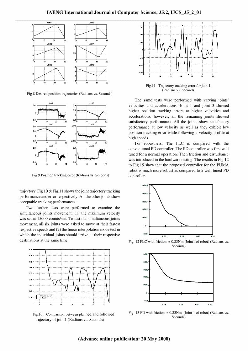
Fig 8 Desired position trajectories (Radians vs. Seconds)
Fig 9 Position tracking error (Radians vs. Seconds)
trajectory. Fig 10 & Fig.11 shows the joint trajectory tracking
performance and error respectively. All the other joints show
acceptable tracking performances.
Two further tests were performed to examine the
simultaneous joints movement: (1) the maximum velocity
was set at 15000 counts/sec. To test the simultaneous joints
movement, all six joints were asked to move at their fastest
respective speeds and (2) the linear interpolation mode test in
which the individual joints should arrive at their respective
destinations at the same time.
Fig.10. Comparison between planned and followed
trajectory of joint1 (Radians vs. Seconds)
Fig.11 Trajectory tracking error for joint1.
(Radians vs. Seconds)
The same tests were performed with varying joints’
velocities and accelerations. Joint 1 and joint 3 showed
higher position tracking errors at higher velocities and
accelerations, however, all the remaining joints showed
satisfactory performance. All the joints show satisfactory
performance at low velocity as well as they exhibit low
position tracking error while following a velocity profile at
high speeds.
For robustness, The FLC is compared with the
conventional PD controller. The PD controller was first well
tuned for a normal operation. Then friction and disturbance
was introduced in the hardware testing. The results in Fig.12
to Fig.15 show that the proposed controller for the PUMA
robot is much more robust as compared to a well tuned PD
controller.
Fig. 12 FLC with friction ≈ 0.23Nm (Joint1 of robot) (Radians vs.
Seconds)
Fig. 13 PD with friction ≈ 0.23Nm (Joint 1 of robot) (Radians vs.
Seconds)
IAENG International Journal of Computer Science, 35:2, IJCS_35_2_01______________________________________________________________________________________
(Advance online publication: 20 May 2008)

Fig. 14 FLC with unit input disturbance
(Radians vs. Seconds)
Fig. 15 PD with unit input disturbance
(Radians vs. Seconds)
Another experiment was done to compare the performance of
our implemented fuzzy controller with LQR and sliding
mode controller. Though the other controller also show good
tracking performance, FLC was able to compensate for some
disturbances and sensing noise as shown in the Fig. 16(a, b
and c).
VII. DISCUSSION AND CONCLUSION
In this paper, the preliminary results are achieved in the
development and implementation of a new simple PC based
replacement controller for PUMA 512 robot. By assembling
.
controller from off-the-shell hardware and software
components, the benefits of reduced and improved
robustness have been realized.
Although the experiments were performed at
educational and research institution, the research is oriented
towards industrial applications
The paper uses the method “Controller Output Error
method (COEM)” for on-line tuning of the fuzzy controller.
This method can be used with any fuzzy controller design;
the only requirement is that the controller must be stable
before initializing the tuning. So any fuzzy rule-based model
can be used to parameterize and initialize the controller of
the system. COEM is subsequently applied to tune the
parameters of fuzzy controller for purpose of achieving
better performance.
Gaussian membership function and the centric method of
fuzzy inference in this paper are chosen as a concrete fuzzy
structure to convey the idea. The method described in
Section 4.3 is not dependent on the choice of membership
function nor the choice of inference mechanism. Whether
one chooses to use, for example, a triangular membership
function or the Takagi-Sugeno inference mechanism, the
method developed in Section 4.3 can be applied directly.
Though, some technical problems were faced while
performing the tests at higher velocities for joint 1 and joint
3, the newly designed hardware and software works very well
and overcomes the problems in the previous PC based design
for PUMA robot. All the joints show satisfactory
performance at low velocity as well as they exhibit low
position tracking error while following a velocity profile at
high speeds.
The experimental results showed that it is feasible to
implement modern control methods for PUMA 500 Series
Robots through software routines running on a PC.
Presently the authors are working to implement and adapt
the system for an industrial CNC milling machine.
(a)
( ( (b)
(c)
Fig.16.Robot Joint 1 tracking performance (a) FLC implementation,
(b) LQR implantation, (c) Slide mode control implementation
IAENG International Journal of Computer Science, 35:2, IJCS_35_2_01______________________________________________________________________________________
(Advance online publication: 20 May 2008)

ACKNOWLEDGMENT
The authors would like to thank to Miss Bai Tingting who
helped us in robot hardware design and Mr. Ye Guohai for
his contribution in mechanical design and assembly. We
would also like to thank Dr. Huang for helping us in
debugging the GUI software in VC++.
REFERENCES
[1] S. Sorenson, Overview of Modular, Industry standard based open
architecture controller, Proc. Intl. Conference of Robots and
Vision Automation, Detroit Michigan, , 1993, USA,
[2] D. J. Miller, R. C. Lenox, An Object Oriented Environment for
Robot system Architecture, Control system magazine, IEEE,
1991, Vol 11, Issue 2, pp. 14-23.
[3]. M. B. Jr. Leahy, S. B. Petroski, Unified Telerobotic
Architecture Project status report, IEEE Intl. Conference
Systems, man and Cybernetics, San Antonio, Texas,1994, Vol.
1, pp. 249-253.
[4]. Unimation Robotics. User’s Guide to VAL 398P2A: A Robot
Programming and Control System, Unimation Inc., Danbury,
Connecticut, 1983, USA.
[5]. R. Vistness, Breaking away from VAL. Technical Report,
Unimation Inc. Danbury, Connecticut, 1982, USA.
[6]. Pan Laingdong, Huang Xinhan., Implementation of a PC-based
robot controller with open architecture, Proceedings. IEEE
International Conference on Robotics and Biometrics, 2004,
pp. 790-794.
[7]. V. M. Becerra, C. N. J. Cage, W. S. Harwin, P. M. Sharkey,
Hardware retrofit and computed torque control of a Puma 560
Robot updating an industrial manipulator. IEEE Control
Systems Magazine, 2004, v 24, no. 5, pp. 78-82
[8]. P. Fiedler, & C. Schlib, Open Architecture Robot Controllers
and Workcell Integration, Robotics Today, 1998, Vol. 11, no.4,
pp. 1-4.
[9]. J. Katupitiya, R. Radajewski, J. Sanderson, M. Tordon,
Implementation of a PC based controller for a PUMA Robot,
Proc. IEEE Conference on Mechatronics and Machine Vision
in Practice, 1997, Australia, pp. 14-19.
[10]. H. C. Anderson, A. Lofti and A. C. Tsoi, A new approach to
adaptive fuzzy control: The controller output error method.
Proc. IEEE conference on system, man and Cybernetics [C].
Part B. 1997, 27(4), 686~691
[11]. V. M. Becerra, S. Cook, J. Deng, Predictive Computed-torque
control of a PUMA 560 Manipulator robot. Proc. 16th IFAC
world congress, 2005, Prague.
[12]. 15. P. I. Corke, Operational Details of the Unimation Puma
Servo System, Report, CSIRO Division of Manufacturing
Technology, 1993, Australia.
[13]. L. Hanho, G. E. Sobelman, VLSI Design of Digit-Serial FPGA
Architecture, Journal of Circuits, Systems, and Computers,
2004, Vol. 13, No. 1
[14]. F. L. Lewis, C. T. Abdallah, & D. M. Dawson, Robot
Manipulator Control, Theory and Practice, 2nd ed., Marcel
Dekker, 2004.
[15]. K. M. Passino.and S. Yurkovich. Fuzzy Control. Menlo Park,
Addison and Wesley Longman, 1998, 250~390.
IAENG International Journal of Computer Science, 35:2, IJCS_35_2_01______________________________________________________________________________________
(Advance online publication: 20 May 2008)
Related Documents