Impact parameter resolution study for ILC detector Tomoaki Fujikawa (Tohoku university) ACFA Workshop in Taipei Nov. 11 2004

Impact parameter resolution study for ILC detector
Jan 01, 2016
Impact parameter resolution study for ILC detector. Tomoaki Fujikawa (Tohoku university) ACFA Workshop in Taipei Nov. 11 2004. Outline. Study the pair e + e - background hit rate for vertex detector with various B fields. (tool:CAIN,Jupiter). - PowerPoint PPT Presentation
Welcome message from author
This document is posted to help you gain knowledge. Please leave a comment to let me know what you think about it! Share it to your friends and learn new things together.
Transcript
Impact parameter resolution study for ILC detector
Tomoaki Fujikawa (Tohoku university)
ACFA Workshop in Taipei
Nov. 11 2004

Outline
Study the pair ee background hit rate for vertex detector with various B fields. (tool:CAIN,Jupiter)
Obtain the impact parameter resolutions with optimized radii. (tool:TRACKERR)
Optimize the vertex detector radii for each B field.

Pair background hit rate studySimulation tools
Monte-Carlo program for the beam-beam interaction. (by Yokoya-san)Included interactions are…
・JupiterJLC Uniform Particle Interaction and Tracking EmulatoR.
GEANT4 based full simulator for ILC (under construction…)
CAIN
photon) virtualmeans ̀(`
` ̀ ̀` Lifshitz-Landau
`` Heitler -Bethe
Wheeler -Breit
ee
ee
ee
(for ee pair background (dominant) generation)
(for pair background hit rate estimation)

Beam parameters (input parameters for CAIN)
)(/104.3
)(3.0 ),(5 (553
)(03.0 ,)(10
(/train)2820n (/bunch),102.0 Ne GeV,500E
234
zyx
yx
b10
CM
scmL
mmnmnm),
mm
Beam parameters are similar to those in the TESLA TDR.
crossing angle = 7mrad.

Detector configuration (for the Jupiter)
Detector is constructed with the Beam pipe, Vertex detector (Ladder construction), Intermediate tracker, Mask, etc. and base geometry is “Old” one. (Namely, designed for “Warm” machine.)
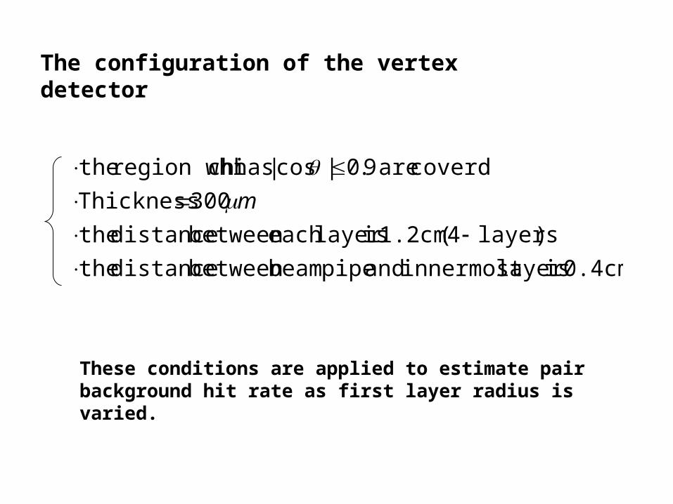
The configuration of the vertex detector
0.4cm islayer innermost and pipe beambetween distance the
) layers4( 1.2cm islayer each between distance the
300 Thickness
coverd are 9.0|cos|hasch region whi the
m
These conditions are applied to estimate pair background hit rate as first layer radius is varied.

Pair background hit rate for the vertex detector1.hit point uniformity (for 1st. layer)
Z
0.9 |cos|
We can use the average hit rate to estimate the occupancy.
B = 3tesla, R1 = 1.2cm.
region. 9.0|cos| within uniform ison distributiHit
Z vs. phi

2. Number of fired pixels per track hit (for 1st. layer)
Number of fired pixel per track hit
Number of fired pixels per 1 track passage is about 3.7. (independent of radius and B field)
m)30 region sensitive theof thickness
m,25 m25 size pixel(sensor

3. Determination of first layer radius
20 readouts per train
3.7 fired pixels per track hit
Pixel occupancy(%) = hit rate (/bunch/cm2) 0.326
Set the first layer radius such that its pixel occupancy = 0.5%

0.5 % occupancy occurs at
3/))2(1exp(0)( pxpxppxf fit function:
tesla)(5 cm 0.0291.554R1
tesla)(4 cm 028.01.694R1
tesla)(3 cm 0.0341.920R1
3 tesla 4 tesla 5 tesla
First layer hit rate vs. first layer radius

Impact parameter resolutions
Use TRACKERR program (also momentum resolution).
Assume pions.
TRACKERR:
FORTRAN program to calculate tracking error matrix with using cylindrically symmetric system.
Energy loss, energy loss fluctuation and multiple scattering effects are included. Track fitting uses Kalman filter.

Detector configurations for TRACKERR
3 tesla 4 tesla 5 teslaBeam pipe (Be)
VTX detector (Si pixel)
IT (Si strip)
TPC
5):2:93
CH:CO:(Ar 42
m250 500, (dBP) thickness, (cm) 0.4RR VTX1bp μ
m50 100, 300, (dVTX) thicknessm,2σ
(4layers), 1.2cm layer each between distance
cm92.1R VTX1 1.69cm 1.55cm
m300 thicknessm,10σ
(5layers), 7cm layer each between distance 3cm,RR
rφ
VTX4IT1
45cm R (2mm,6mm),y)(x,:size Pad m,150σ innerrφ
200cm R outer 160cm 130cm

Impact parameter resolutions of the r-phi plane
case m50 dVTX m,250 dBP :ex
required.) are m10B and m5A
./sinB/P)(Arelation for the
parametersfit are B andA table,bellow in the(
322
Impact parameter resolutions are mostly the same for each magnetic field case. (true for other configurations with different thickness for BP and VTX detector.)
m)( resolution IP vs.P(GeV/c) 90 anglepolar at m)( sresolutionparameter Impact
P = 1.0GeV/ c P = 10GeV/ c P = 100GeV/ c A(micron) B(micron)B = 3tesla 8.84 2.47 1.39 1.44 11.12B = 4tesla 7.79 2.34 1.43 1.49 9.56B = 5tesla 7.16 2.27 1.48 1.53 8.66

Other configuration results are as follows (at polar angle = 90 deg.):
small. quite are sdifference But the cases. 5tesla 4, B
nbetter tha is case 3tesla B 30GeV/c,~ PFor
90 anglepolar at m)( sresolutionparameter Impact
For P = 1GeV/c 3tesla is worse than 4(5) tesla by 12.0(19.2) %.
For P = 10GeV/c 3tesla is worse than 4(5) tesla by 6.4(8.8) %.
dBP (micron) dVTX(micron) B (tesla) P = 1.0GeV/ c P = 10GeV/ c P = 100GeV/ c A(micron) B(micron)3 16.22 3.33 1.44 1.33 22.314 14.24 3.08 1.47 1.38 19.385 13.03 2.94 1.52 1.37 18.453 10.57 2.69 1.40 1.42 13.694 9.32 2.52 1.44 1.47 11.835 8.56 2.44 1.49 1.49 10.963 8.84 2.47 1.39 1.44 11.124 7.79 2.34 1.43 1.49 9.565 7.16 2.27 1.48 1.53 8.66
500 300
100
50
250

Momentum resolutions
case m50 dVTX and m250 dBP:ex
P/ resolution momentum vs.P(GeV/c) P
Momentum resolution is better for high B at low P, and better for low B at high P.
P = 1.0GeV/ c P = 10GeV/ c P = 100GeV/ cB = 3tesla 1.50E- 03 1.38E- 03 3.82E- 03B = 4tesla 1.40E- 03 1.50E- 03 4.29E- 03B = 5tesla 1.35E- 03 1.75E- 03 5.10E- 03
90 anglepolar at P)/( sresolution Momentum P

Other configuration results are as follows (at polar angle = 90 deg.):
90 anglepolar at P)/( sresolution Momentum P
Momentum resolution is better for high B at low P, and better for low B at high P.
dBP (micron) dVTX(micron) B (tesla) P = 1.0GeV/ c P = 10GeV/ c P = 100GeV/ c3 1.50E- 03 1.38E- 03 3.83E- 034 1.42E- 03 1.51E- 03 4.31E- 035 1.37E- 03 1.78E- 03 5.12E- 033 1.51E- 03 1.38E- 03 3.82E- 034 1.41E- 03 1.50E- 03 4.30E- 035 1.36E- 03 1.76E- 03 5.10E- 033 1.50E- 03 1.38E- 03 3.82E- 034 1.40E- 03 1.50E- 03 4.29E- 035 1.35E- 03 1.75E- 03 5.10E- 03
300
100
50
500
250

Comparison with other detector configurations
1. TESLA detector:
detectors) above as same are etc. size Pad ,(
170cm radiusouter 32cm, radiusinner :TPC
m300 thicknesslayers),-(2 30cm 16cm,R :strip) IT(Si
m300 kness thic
layers),-(5 6.0cm 4.8cm, 3.7cm, 2.6cm, 1.5cm,R:pixel) VTX(Si
m500 thicknesscm,4.1R :BP
4teslaB
IT
VTX
bp

Comparison between TESLA and 3 tesla case
m)300 dVTX m,500 dBP(
P = 1.0GeV/ c P = 10GeV/ c P = 100GeV/ c A(micron) B(micron)TESLA 13.22 2.86 1.47 1.60 15.95
GLD 16.22 3.33 1.44 1.33 22.31
90 anglepolar with m)( sresolutionparameter Impact

Comparison between TESLA and 3 tesla case
m)300 dVTX m,500 dBP(
P = 1.0GeV/ c P = 10GeV/ c P = 100GeV/ cTESLA 1.36E- 03 1.21E- 03 4.16E- 03GLD 1.50E- 03 1.38E- 03 3.83E- 03
90 anglepolar with P)/( sresolution Momentum P

2.New VTX detector configuration (proposed by Sugimoto-san):
detector) above as same are etc. IT for the s(condition
m50 s thicknes
,doublets))layer (3 layers-(6 5.0cm 4.8cm, 3.2cm, 3.0cm, 2.2cm, 2.0cm, R VTX
Layer
Polystyrene foamVTX detector

Comparison between double and single layer (3 tesla)
m) 50 dVTX m, 250 (dBP
P = 1.0GeV/ c P = 10GeV/ c P = 100GeV/ c A(micron) B(micron)double layer 11.18 2.40 1.18 1.29 12.78single layer 8.84 2.47 1.39 1.44 11.12
90 anglepolar with m)( sresolutionparameter Impact

Comparison between double and single layer (3 tesla)
m) 50 dVTX m, 250 (dBP
90 anglepolar with P)/( sresolution momentum P
P = 1.0GeV/ c P = 10GeV/ c P = 100GeV/ cdouble layer 1.50E- 03 1.38E- 03 3.80E- 03single layer 1.50E- 03 1.38E- 03 3.82E- 03

Other configuration results:
90 anglepolar with P)/( sresolution momentum P
Momentum resolutions are mostly the same as single layer case, but impact parameter resolutions are different. (single layer case does not have support design yet.)
90 anglepolar with m)( sresolutionparameter Impact
m) 50 dVTX m, 250 (dBP
B (tesla) P = 1.0GeV/ c P = 10GeV/ c P = 100GeV/ c A(micron) B(micron)3 11.18 2.40 1.18 1.29 12.784 11.15 2.40 1.25 1.34 12.865 11.14 2.42 1.34 1.38 12.853 8.84 2.47 1.39 1.44 11.124 7.79 2.34 1.43 1.49 9.565 7.16 2.27 1.48 1.53 8.66
double layer
single layer
B (tesla) P = 1.0GeV/ c P = 10GeV/ c P = 100GeV/ c3 1.50E- 03 1.38E- 03 3.80E- 034 1.41E- 03 1.50E- 03 4.27E- 035 1.36E- 03 1.75E- 03 5.08E- 033 1.50E- 03 1.38E- 03 3.82E- 034 1.40E- 03 1.50E- 03 4.29E- 035 1.35E- 03 1.75E- 03 5.10E- 03
double layer
single layer

Summary and Plan
Impact parameter resolution and momentum resolution are mostly the same in each B field case. (More detailed study (namely, b- and c-taging efficiency study) is needed to estimate the best B field.)
Thickness of the detector components are quite important to obtain the good impact parameter resolution.
Plan
Summary
Estimate the impact parameter resolutions (and more) by using a full simulator. (To do so, development of the simulator is necessary…)
Related Documents


