1 Impact on thermoplastic fibre-metal laminates: preliminary results and observations Rafael Santiago Group of Solid Mechanics and Structural Impact Department of Mechatronics and Mechanical Systems Engineering University of São Paulo [email protected] Wesley Cantwell Department of Engineering University of Liverpool [email protected] Marcílio Alves Group of Solid Mechanics and Structural Impact Department of Mechatronics and Mechanical Systems Engineering University of São Paulo [email protected] 1 ABSTRACT Fibre-metal laminates (FML) are a combination of layers of composite and metal materials. They have been used in high performance airplane structures due to its long fatigue life and good performance to impact loads. In this work, a new generation of FML using thermoplastic composite (or TFML), made by aluminum and self-reinforced polypropylene, was studied for the case of impact loads. The three partite analyses cover theoretical, numerical and experimental procedures. A series of low and high velocity impact events were carried out on the TFML, identifying its response. The TFML was mechanically characterized for a wide range of strain rates and its behavior was properly assessed by a numerical material model. Theoretical formulations were used to predict the residual displacement and ballistic limit of TFML circular plates. A TFML finite element model was also developed and preliminary results of this analysis is here given. Keywords: Fibre-metal laminates, composite materials, thermoplastic composites, lightweight structures. 2 INTRODUCTION The aerospace industry is continuously looking for developing new materials. Composite materials have been preferred above conventional metals, thanks to its high specific strength/stiffness and fatigue resistance. However, the mechanical properties of metals cannot be disregarded and in this scenario a combination of metals and composite materials has been developed. The so called hybrid materials have then been developed as a combination of thin layers of metals and fibre-reinforced composites. Hybrid materials, known as Fibre-Metal Laminates,

Welcome message from author
This document is posted to help you gain knowledge. Please leave a comment to let me know what you think about it! Share it to your friends and learn new things together.
Transcript
1
Impact on thermoplastic fibre-metal laminates: preliminary results and
observations
Rafael Santiago Group of Solid Mechanics and Structural Impact
Department of Mechatronics and Mechanical Systems Engineering University of São Paulo
Wesley Cantwell Department of Engineering
University of Liverpool [email protected]
Marcílio Alves
Group of Solid Mechanics and Structural Impact Department of Mechatronics and Mechanical Systems Engineering
University of São Paulo [email protected]
1 ABSTRACT
Fibre-metal laminates (FML) are a combination of layers of composite and metal materials. They have been used in high performance airplane structures due to its long fatigue life and good performance to impact loads. In this work, a new generation of FML using thermoplastic composite (or TFML), made by aluminum and self-reinforced polypropylene, was studied for the case of impact loads. The three partite analyses cover theoretical, numerical and experimental procedures. A series of low and high velocity impact events were carried out on the TFML, identifying its response. The TFML was mechanically characterized for a wide range of strain rates and its behavior was properly assessed by a numerical material model. Theoretical formulations were used to predict the residual displacement and ballistic limit of TFML circular plates. A TFML finite element model was also developed and preliminary results of this analysis is here given.
Keywords: Fibre-metal laminates, composite materials, thermoplastic composites, lightweight structures.
2 INTRODUCTION
The aerospace industry is continuously looking for developing new materials. Composite materials have been preferred above conventional metals, thanks to its high specific strength/stiffness and fatigue resistance. However, the mechanical properties of metals cannot be disregarded and in this scenario a combination of metals and composite materials has been developed. The so called hybrid materials have then been developed as a combination of thin layers of metals and fibre-reinforced composites. Hybrid materials, known as Fibre-Metal Laminates,

IV International Symposium on Solid Mechanics - MecSol 2013 April 18 - 19, 2013 - Porto Alegre - Brazil
2
FML, present superior fatigue and failure characteristic, associated to the fibre-reinforced composite, combined with the good durability, machinability and plastic behavior of metals. A commercial example of a FML is the GLARE, developed at Delft University of Technology in the 80’s and currently used in many parts of the AIRBUS A-380 structure. GLARE is the combination of thin layers of aluminum and glass/epoxy laminates. Many author [1-3] reported superior performance of GLARE under blast, low and high velocity impact events, when compared to monolithic aeronautical aluminum alloys, such as 7075-T6 or 2024-T3, and carbon/epoxy composites. One reason of its high-performance is the combination of the visco-plastic behavior of the aluminum combined with the high energy absorption of the composite.
New generations of FML have been developed based on thermoplastic composites and high strength fibers. Polypropylene (PP) is mainly used due to its low cost, recyclability and the possibility of properties handling by adding different additives [4-6]. This material usually is offered as glass/PP composite or self-reinforced PP (SRPP). These FML offer improved toughness due to the higher energy required for first failure and due to its high ultimate strength. They also combine higher impact resistance, low density and rapid/low-cost manufacturing.
Carrillo and Cantwell [7] identified the tensile, flexural and adhesive interface properties of a thermo fiber-metal laminate, TFML, made by SRPP named Curv, under quasi-static regimen. High energy absorption under low impact velocity was also observed in this study. Abdulla and Cantwell [8] developed a series of high velocity impact tests under the same TFML, observing the potential use for lightweight energy-absorption structures. The performance of TFML under blast loads was studied by Langdon et al. [8-9] using different stacked configuration.
Few numerical analyses are available for FML materials and structures. Karagiozova et al. [10] developed a numerical model able to predict the TFML behavior under blast loads. In this study, the metal-polymer interface properties and the strain rate effects were considered. Recently, Fan et al. [11] developed a numerical model able to predict the TFML behavior subjected to low-velocity loads.
In this work, TFML material and circular plates is presented, covering experimental impact events, mechanical characterization, theoretical and numerical analysis. A TFML circular plate was subjected to low and high impact loads, so determining the critical minimal velocity for visual cracking and the ballistic limit, respectively. The TFML constituents were characterized at different strain rates, proving constitutive parameters for numerical and established theoretical models, also presented here.
3 MANUFACTURING AND MATERIAL DETAILS
A 4/3 TFML configuration was chosen as a reference for this study. It comprises four layers of 0.4 mm thick aluminium 2024-T3 sheets, intercalated with 3 reinforced layers. This is a self-reinforced polypropylene (SRPP), named PURE, manufactured by Lanhorst Composite Bv. It is a hybrid PP tape woven in a balanced plain weave fabric. Each tape has an internal high unidirectional PP, involved in a modified PP which provides the adhesion to the next layer, with no damage to the internal material. Four SRPP fabrics were used in each TFML reinforced layer, with the reinforced tapes aligned or perpendicular to the aluminium lamination direction. A 0.05 mm thick Collan Xiro PP adhesive was used between all metal-polymer interfaces. The aluminium sheets were anodized to enhance the interlayer TFML adhesion.
The TFML samples were made by thermoforming technique, following the procedure suggested by the manufacturer [12]. First, the metal sheets, SRPP layers and adhesive films were cut, aligned and stacked, and then fixed between two flat moulds. This assembly was put in a hot press machine under the pressure of 10 bar and heated at the rate of 5ºC per second until the 135ºC. 5 minutes is needed for consolidation of the material, which is then cooled down at a rate of 1oC per

IV International Symposium on Solid Mechanics - MecSol 2013 April 18 - 19, 2013 - Porto Alegre - Brazil
3
minute. A 200 x 200 mm2 flat TFML was made at once. This procedure is shown in Figure 1 and the TFML metal and reinforcement volume fractions ( Alx and SRPPx , respectively) and volume
densities, TFML ,are listed in Table 1.
(a) (b)
Figure 1: TFML samples made by thermoforming technique: (a) Hot press machine and (b) TFML constituents (from left to right: anodized aluminium 2024-T3, Collano Xiro adhesive film and
SRPP Lankhorst Pure.
Table 1 TFML constituent volume fractions.
4/3 TFML physical properties
AL SRPP Alx Alx TFML
2700 kg/m3 780 kg/m3 57% 43% 1874.4 kg/m3
The low/high velocity samples were made by cutting the TFML plate into pieces of 100 x 100
mm2 using a shear guillotine, and eight 8 mm of diameter holes were made in a drill machine, for fixing the plate in the 80 mm of diameter circular fixture assemble. Samples for mechanical characterization test were extracted from monolithic aluminium 2024-T3 and from SRPP 1.3 mm thick sheets.
4 THEORETICAL MODELS
4.1 Low velocity impact
The perfectly plastic impact theoretical model, developed by Jones [13], was used for predicting the TFML residual central displacement when subjected to low velocity impact. In this, a fully clamped circular plate of radius R and thickness H is struck at the centre by a rigid cylindrical striker of radius a , mass G and travelling at the velocity of 0V , as shown in Figure 2. Equations 1-
3 model this event:

IV International Symposium on Solid Mechanics - MecSol 2013 April 18 - 19, 2013 - Porto Alegre - Brazil
4
v
u Cu
uur
n
m Cm
mmrr
A
rrr
A
dCwQ
dCrwwNM
dAwNMwNM
dAwwWWG
1
1
00
/
(1)
r
drwd / and
2
2
dr
wdr
(2)
L
xWw
1
(3)
(a) (b)
(c)
Figure 2: (a) Low velocity impact model, (b) linear impacted plate profile, and (c) inscribed and circumscribed yield surface coupling normal and membrane loads.
In Equation 1, the work rate due to inertia forces are represented by the terms on the left hand
side, where A is the surface area and is the mass per mid plane unit area of the circular plate. The first term on the right hand side is the energy dissipated in the continuous axisymmetric deformation fields. The second term models the energy dissipated in n axisymmetric plastic

IV International Symposium on Solid Mechanics - MecSol 2013 April 18 - 19, 2013 - Porto Alegre - Brazil
5
bending hinges, each having an angular velocity mrw / across the hinge of length mC .The final
term is the plastic energy absorption in axisymmetric transverse shear hinges, each having a velocity uw and length uC . Equation 1 considers that external work rate equals the internal
energy dissipation. The impact phenomenon can be divided in two phases: the first, when the transverse shear
effects and bending moments were considered. In the second stage, the bending moments and membrane forces dominate the motion. The first phase ceases when the yield condition is reached, defined by oM , triggering the second stage. Since large displacements are expected, the shear
effects are rapid reduced faced to membrane forces [14], so the first phase of movement was ignored. It is important to emphasize that this model cannot be applicable beyond the material failure.
40
0
HNM or
4
2
0
HM o
(4)
A linear velocity profile (Equation 3) was considered for the plate velocity during the impact,
as shown in Figure 2. As presented in Figure 2, the definition of the yield conditions defines a parabolic relationship between bending moment, M , and membrane forces, N . This coupling can be simplified by the use of an inscribing and a circumscribing square yield surface, which provides two boundaries for the model. With these assumptions, Equation 1 can be reduced to:
fWgW 2 , (5)
with the expressions below being valid for the inscribing and circumscribing yield surfaces:
6/23
/22
0
aRaRG
aRaRNg
and
6/23
/422
0
aRaRG
aRRMg
(6)
Conservation of linear moment gives the initial velocity of the plate centre as:
12
0
0
3
11
V
W, (7)
where
2R
G
and
R
a (8)
The residual central displacement is given by solving equation 5 with initial conditions given
by Eq. 7, and considering that the movement ceases when W0=0.
1
138
3216131
1
1 21
2
222max
H
W (9)
IV International Symposium on Solid Mechanics - MecSol 2013 April 18 - 19, 2013 - Porto Alegre - Brazil
6
HM
RV
0
220
(10)
The TFML perfect plastic flow stress, tFMLp, , was obtained using the rule of mixture,
considering the TFML metal and reinforcement fractions and their respective yield stress. The considered TFML plastic bending moment, tFMLM ,0 , is presented in Equation 11:
SRPPSRPPpAlAlptFMLp xx ,,, (11)
3,,
2204
Hxx
RV
SRPPSRPPpAlAlptFML
(12)
4.2 High velocity impact
Reid and Wen perforation model [14] was used here for predicting the ballistic limit of the TFML under high velocity impact events. In this, the tension applied to the circular plate by the
target is separated in two components: one associated to the tension due to material elastic-plastic static deformations, s , and the second associated to dynamic loading effects, d .
Here, the elastic-plastic static limit was assumed as the TFML perfect plastic behaviour, defined by the rule of mixture and presented in Equation 11 ( tFMLps , ). The dynamic resistive
tension, d , can be written as equation 14.
ds (13)
2
1
,0,005.1
FML
tFMLFMLd V
(14)
Regarding the ballistic limit, here it is adopted the model by Reid and Wen [14] who obtained
the ballistic limit ( bV ) of the TFML as
(15)
Ha
G
G
HaV
TFML
tFMLoTFML
b 2
2,
9
811
2
3
(16)
5 EXPERIMENTAL SET UP
5.1 Low velocity impact tests
In this study, a low velocity impact was considered as an event with projectile velocity up to 10 m/s. A drop weight machine was used to perform these impact tests on the TFML samples. An impact mass of 4.6 kg and a semi-hemispherical 20.0 mm diameter indenter were used. The TFML
IV International Symposium on Solid Mechanics - MecSol 2013 April 18 - 19, 2013 - Porto Alegre - Brazil
7
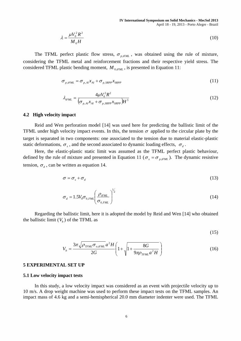
samples were fixed in a circular 80.0 mm diameter rigid fixture apparatus, with eight M8 screws and internal grooves to prevent radial motion. The apparatus set up is presented in Figure 3.
Figure 3: Low velocity impact test set up.
A laser velocity sensor Polytec OFV-323 was used for monitoring the indenter velocity,
displacement and force during the impact test, recorded by a National Instruments PCI-6550 acquisition board at a rate of 10 kHz. It was also used a Photron APX-RS high speed camera operating at a rate of 5,000 fps to provide visual information from the testes.
The aim of these experiments is to identify the minimal velocity for visual crack initiation,
CIV , for the TFML studied. In addition, the force history, incident and residual velocity were
recorded for each sample tested. Crescent impact velocities were adopted, until a visual crack could be observed. Only one impact event was applied to each sample and secondary impact loads were inhibited. Two impact tests were performed for each chosen impact velocity. After impact, the residual central displacement was measured using a linear displacement gauge.
5.2 High velocity impact tests
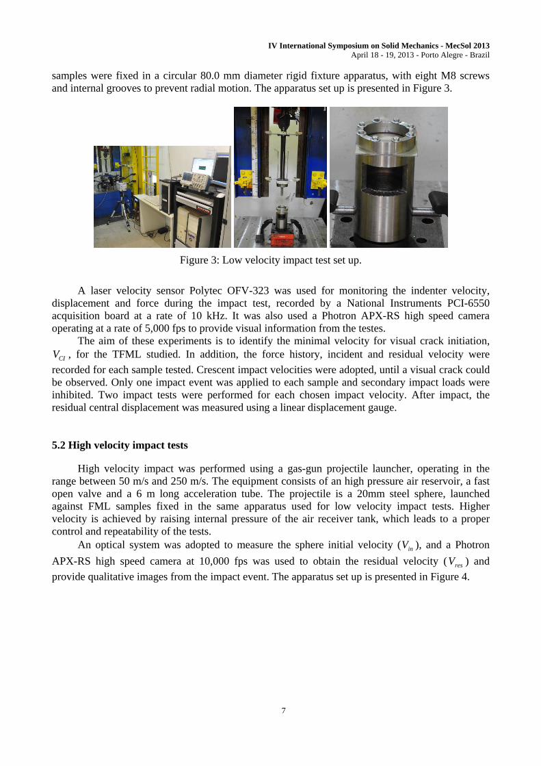
High velocity impact was performed using a gas-gun projectile launcher, operating in the range between 50 m/s and 250 m/s. The equipment consists of an high pressure air reservoir, a fast open valve and a 6 m long acceleration tube. The projectile is a 20mm steel sphere, launched against FML samples fixed in the same apparatus used for low velocity impact tests. Higher velocity is achieved by raising internal pressure of the air receiver tank, which leads to a proper control and repeatability of the tests.
An optical system was adopted to measure the sphere initial velocity ( inV ), and a Photron
APX-RS high speed camera at 10,000 fps was used to obtain the residual velocity ( resV ) and
provide qualitative images from the impact event. The apparatus set up is presented in Figure 4.
IV International Symposium on Solid Mechanics - MecSol 2013 April 18 - 19, 2013 - Porto Alegre - Brazil
8
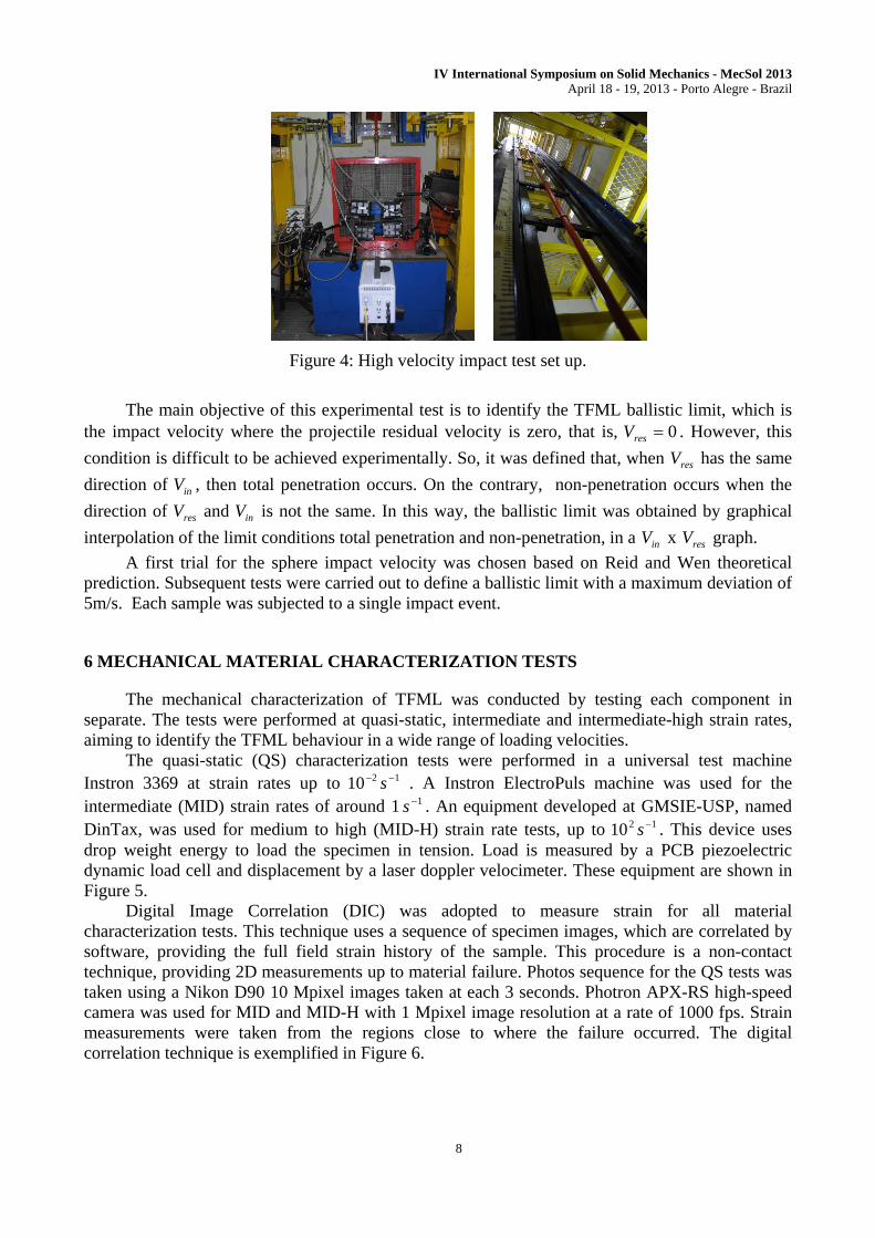
Figure 4: High velocity impact test set up.
The main objective of this experimental test is to identify the TFML ballistic limit, which is
the impact velocity where the projectile residual velocity is zero, that is, 0resV . However, this
condition is difficult to be achieved experimentally. So, it was defined that, when resV has the same
direction of inV , then total penetration occurs. On the contrary, non-penetration occurs when the
direction of resV and inV is not the same. In this way, the ballistic limit was obtained by graphical
interpolation of the limit conditions total penetration and non-penetration, in a inV x resV graph.
A first trial for the sphere impact velocity was chosen based on Reid and Wen theoretical prediction. Subsequent tests were carried out to define a ballistic limit with a maximum deviation of 5m/s. Each sample was subjected to a single impact event.
6 MECHANICAL MATERIAL CHARACTERIZATION TESTS
The mechanical characterization of TFML was conducted by testing each component in separate. The tests were performed at quasi-static, intermediate and intermediate-high strain rates, aiming to identify the TFML behaviour in a wide range of loading velocities.
The quasi-static (QS) characterization tests were performed in a universal test machine Instron 3369 at strain rates up to 1210 s . A Instron ElectroPuls machine was used for the intermediate (MID) strain rates of around 1 1s . An equipment developed at GMSIE-USP, named DinTax, was used for medium to high (MID-H) strain rate tests, up to 1210 s . This device uses drop weight energy to load the specimen in tension. Load is measured by a PCB piezoelectric dynamic load cell and displacement by a laser doppler velocimeter. These equipment are shown in Figure 5.
Digital Image Correlation (DIC) was adopted to measure strain for all material characterization tests. This technique uses a sequence of specimen images, which are correlated by software, providing the full field strain history of the sample. This procedure is a non-contact technique, providing 2D measurements up to material failure. Photos sequence for the QS tests was taken using a Nikon D90 10 Mpixel images taken at each 3 seconds. Photron APX-RS high-speed camera was used for MID and MID-H with 1 Mpixel image resolution at a rate of 1000 fps. Strain measurements were taken from the regions close to where the failure occurred. The digital correlation technique is exemplified in Figure 6.

IV International Symposium on Solid Mechanics - MecSol 2013 April 18 - 19, 2013 - Porto Alegre - Brazil
9
(a) (b) (c)
Figure 5: Mechanical characterization equipment used: (a) Instron 3369, (b) Instron ElectroPuls and (c) Dintax.
Figure 6: DIC technique. The specimens were painted with a black and white random pattern to enhance software accuracy.
Aluminium 2024-T3 was tested at QS, MID and MID-H strain rate, using dog-boned-shaped specimens. In QS test, the specimen geometry was based on ASTM-E8M standard, with 70 mm gauge length, 10 mm width and 12.5 mm of round radius. The MID samples were based on reference [16] and have a 5 mm gauge length, 4 mm width and 2 mm round radius. The MID-H test samples has 20 mm gauge length, 10 mm width, 30 mm of round radius and a special grip designed for the equipment. All the aluminium specimen designs were tested quasi-statically, using DIC strain measurement technique.
The SRPP Pure was characterized in QS tests at [0º/90º] and [+/- 45º] directions. The specimen geometry was based on ASTM-3039 standard. It adopts a straight side design, with 150 mm gauge length and 25 mm wide. The specimen geometries are presented in Figure 7. Five samples were considered for these tests and an average behaviour was identified.

IV International Symposium on Solid Mechanics - MecSol 2013 April 18 - 19, 2013 - Porto Alegre - Brazil
10
(a) (b) (c) (d)
Figure 7: Specimen configuration geometries used: (a) Aluminium QS test, (b) Aluminium MID test, (c) Aluminium MID-H test and (d) SRPP QS test.
5 NUMERICAL MODEL
LS-Dyna v.971 was used for the TFML explicit impact numerical simulation. This software offers comprehensive control of the simulation parameters and materials models. Altair Hyper Mesh and LS-PrePost were used for pre and post analysis.
The specimen geometry used in the actual mechanical characterization tests were modelled and the experimental and numerical strain-stress curves were compared. The specimen models are presented in Figure 8.
(a) (b)
Figure 8: Specimen models used for material response calibration: (a) Aluminium and (b) SRPP models.
The TFML model uses thick shell and solid elements, depending on the material model used. The TFML was modelled with three elements across each layer and the metal-reinforcement interfaces was modelled as perfectly bonded. A rigid 20 mm diameter sphere impacts the plate centre, with mass and initial velocity defined according to the impact phenomena studied. The TFML circular plate was fully clamped along the boundaries.
Mesh sensitivity studies were performed for element sizes in the range 2.5 x 2.5 mm2 up to 0.2 x 0.2 mm2. It was observed that 0.8 x 0.8 mm2 meshes provides a better combination of processing time and model response, being then adopted for all the analysis made. The TFML model numerical used is presented in Figure 9.
IV International Symposium on Solid Mechanics - MecSol 2013 April 18 - 19, 2013 - Porto Alegre - Brazil
11
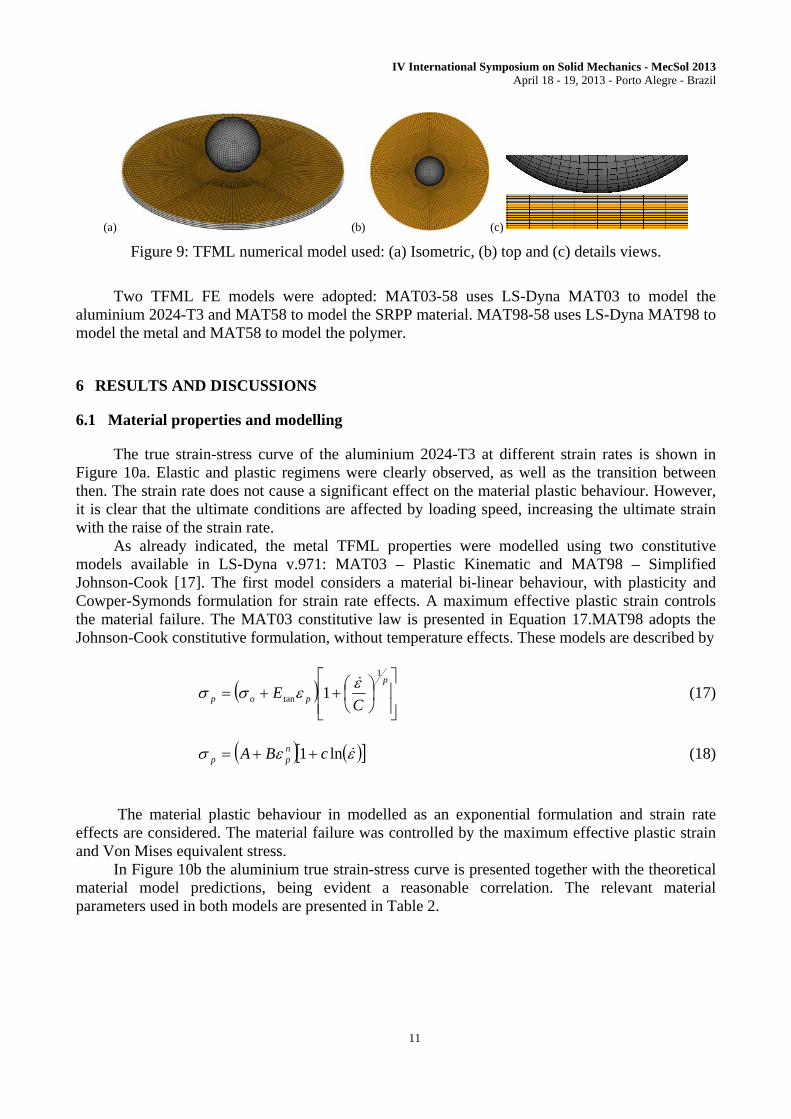
(a) (b) (c)
Figure 9: TFML numerical model used: (a) Isometric, (b) top and (c) details views.
Two TFML FE models were adopted: MAT03-58 uses LS-Dyna MAT03 to model the
aluminium 2024-T3 and MAT58 to model the SRPP material. MAT98-58 uses LS-Dyna MAT98 to model the metal and MAT58 to model the polymer.
6 RESULTS AND DISCUSSIONS
6.1 Material properties and modelling
The true strain-stress curve of the aluminium 2024-T3 at different strain rates is shown in Figure 10a. Elastic and plastic regimens were clearly observed, as well as the transition between then. The strain rate does not cause a significant effect on the material plastic behaviour. However, it is clear that the ultimate conditions are affected by loading speed, increasing the ultimate strain with the raise of the strain rate.
As already indicated, the metal TFML properties were modelled using two constitutive models available in LS-Dyna v.971: MAT03 – Plastic Kinematic and MAT98 – Simplified Johnson-Cook [17]. The first model considers a material bi-linear behaviour, with plasticity and Cowper-Symonds formulation for strain rate effects. A maximum effective plastic strain controls the material failure. The MAT03 constitutive law is presented in Equation 17.MAT98 adopts the Johnson-Cook constitutive formulation, without temperature effects. These models are described by
p
pop CE
1
tan 1
(17)
ln1 cBA n
pp (18)
The material plastic behaviour in modelled as an exponential formulation and strain rate
effects are considered. The material failure was controlled by the maximum effective plastic strain and Von Mises equivalent stress.
In Figure 10b the aluminium true strain-stress curve is presented together with the theoretical material model predictions, being evident a reasonable correlation. The relevant material parameters used in both models are presented in Table 2.
IV International Symposium on Solid Mechanics - MecSol 2013 April 18 - 19, 2013 - Porto Alegre - Brazil
12
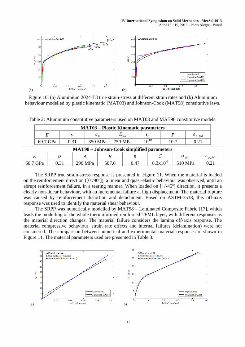
(a) (b)
Figure 10: (a) Aluminium 2024-T3 true strain-stress at different strain rates and (b) Aluminium behaviour modelled by plastic kinematic (MAT03) and Johnson-Cook (MAT98) constitutive laws.
Table 2: Aluminium constitutive parameters used on MAT03 and MAT98 constitutive models.
MAT03 – Plastic Kinematic parameters
E 0 tanE C P failp,
60.7 GPa 0.31 350 MPa 750 MPa 1010 10.7 0.21
MAT98 – Johnson-Cook simplified parameters
E A B n C fail failp,
60.7 GPa 0.31 290 MPa 507.6 0.47 8.3x10⁻³ 510 MPa 0.21 The SRPP true strain-stress response is presented in Figure 11. When the material is loaded
on the reinforcement direction ([0º/90º]), a linear and quasi-elastic behaviour was observed, until an abrupt reinforcement failure, in a tearing manner. When loaded on [+/-45º] direction, it presents a clearly non-linear behaviour, with an incremental failure at high displacement. The material rupture was caused by reinforcement distortion and detachment. Based on ASTM-3518, this off-axis response was used to identify the material shear behaviour.
The SRPP was numerically modelled by MAT58 – Laminated Composite Fabric [17], which leads the modelling of the whole thermoformed reinforced TFML layer, with different responses as the material direction changes. The material failure considers the lamina off-axis response. The material compressive behaviour, strain rate effects and internal failures (delamination) were not considered. The comparison between numerical and experimental material response are shown in Figure 11. The material parameters used are presented in Table 3.
(a) (b)
IV International Symposium on Solid Mechanics - MecSol 2013 April 18 - 19, 2013 - Porto Alegre - Brazil
13
Figure 11: SRPP Pure experimental and numerical materials responses comparison: (a) at [0º/90º] direction and (b) at [+/-45º].
Table 3: SRPP Pure parameters used on MAT58 constitutive models.
MAT58 – Laminated composite fabric parameters
ba EE 12 abG 1 1 22,11, ff 22,11, ff 12,f 12,f
1.6 GPa 0.11 330 MPa 14MPa 0.1 0.11 165 MPa 32 MPa 0.54 For the theoretical models, an equivalent MPaTFMLp 120, provided better results, obtained
by the use of rules of mixture of the metal and SRPP behaviour.
6.2 Low velocity impact test
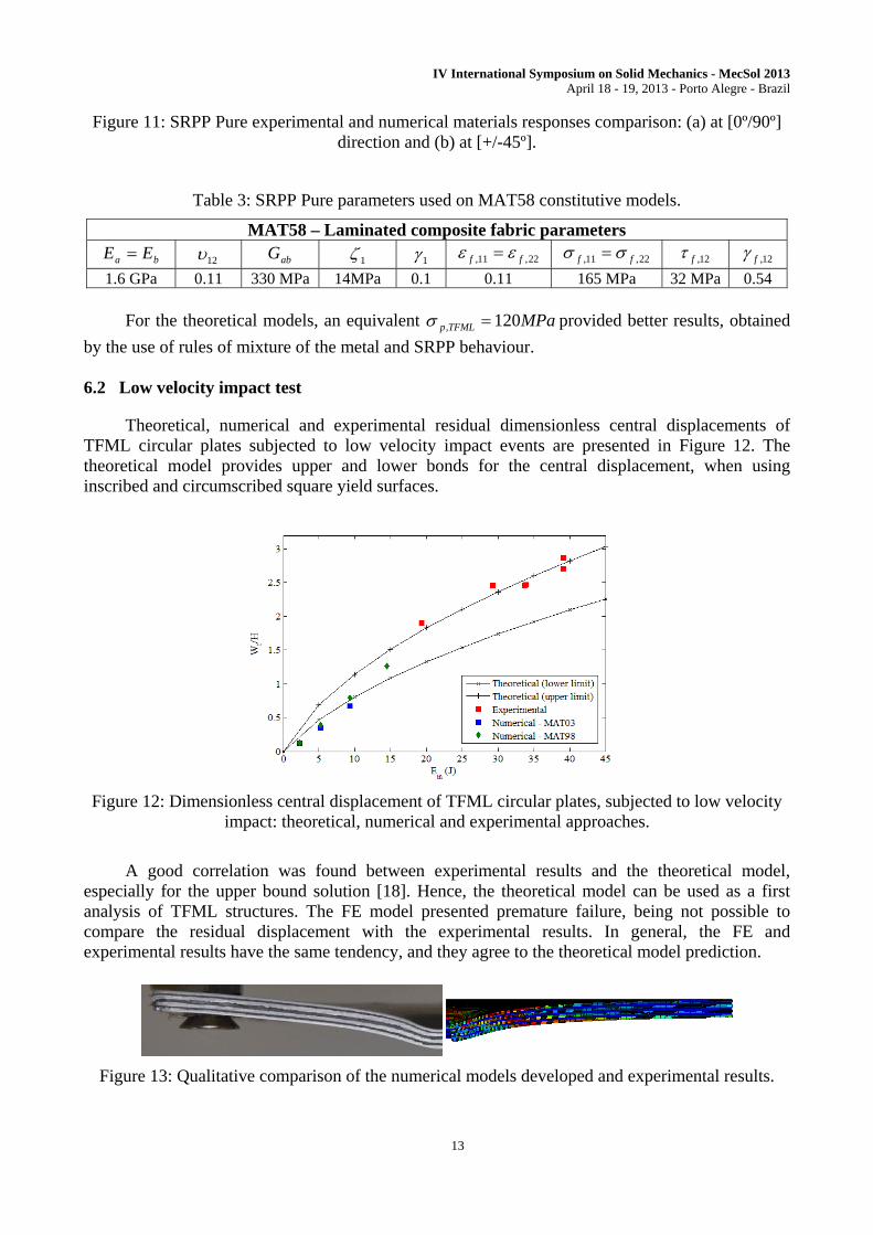
Theoretical, numerical and experimental residual dimensionless central displacements of TFML circular plates subjected to low velocity impact events are presented in Figure 12. The theoretical model provides upper and lower bonds for the central displacement, when using inscribed and circumscribed square yield surfaces.
Figure 12: Dimensionless central displacement of TFML circular plates, subjected to low velocity impact: theoretical, numerical and experimental approaches.
A good correlation was found between experimental results and the theoretical model,
especially for the upper bound solution [18]. Hence, the theoretical model can be used as a first analysis of TFML structures. The FE model presented premature failure, being not possible to compare the residual displacement with the experimental results. In general, the FE and experimental results have the same tendency, and they agree to the theoretical model prediction.
Figure 13: Qualitative comparison of the numerical models developed and experimental results.
IV International Symposium on Solid Mechanics - MecSol 2013 April 18 - 19, 2013 - Porto Alegre - Brazil
14
Figure 13 presents the specimen profile when subjected to an impact velocity close to 3 m/s. A good adhesion between metal and SRPP was observed, with no visual detachment along the metal-polymer interfaces. Large residual displacement was observed on the metal and polymer layers. Although no visual failure was found on this experimental test, the FE model presented failed elements at the impacted region. No qualitative difference was found between the models MAT03-98 and MAT98-58.
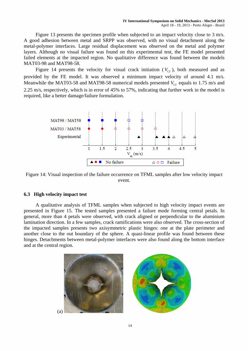
Figure 14 presents the velocity for visual crack initiation ( CIV ), both measured and as
provided by the FE model. It was observed a minimum impact velocity of around 4.1 m/s. Meanwhile the MAT03-58 and MAT98-58 numerical models presented CIV equals to 1.75 m/s and
2.25 m/s, respectively, which is in error of 45% to 57%, indicating that further work in the model is required, like a better damage/failure formulation.
Figure 14: Visual inspection of the failure occurrence on TFML samples after low velocity impact event.
6.3 High velocity impact test
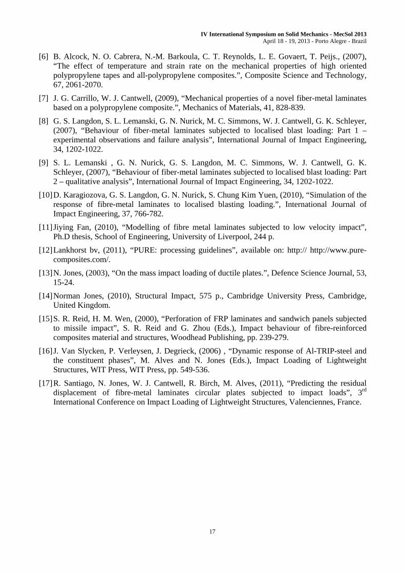
A qualitative analysis of TFML samples when subjected to high velocity impact events are presented in Figure 15. The tested samples presented a failure mode forming central petals. In general, more than 4 petals were observed, with crack aligned or perpendicular to the aluminium lamination direction. In a few samples, crack ramifications were also observed. The cross-section of the impacted samples presents two axisymmetric plastic hinges: one at the plate perimeter and another close to the out boundary of the sphere. A quasi-linear profile was found between these hinges. Detachments between metal-polymer interfaces were also found along the bottom interface and at the central region.
(a)

IV International Symposium on Solid Mechanics - MecSol 2013 April 18 - 19, 2013 - Porto Alegre - Brazil
15
(b)
Figure 15: Qualitative comparison between numerical and experimental results from high velocity impact tests: (a) top and (b) cross-section view.
The entire FE model studied presented a four-petals failure mode, probably caused by symmetry made in the element mesh, and the plastic hinges could not been observed in the impacted profile. No qualitative differences were observed between the models MAT03-58 and MAT98-58. Figure 16 presents the resin VV curve of the experimental and numerical models, with
Table 4 presenting the expected ballistic limit.
Figure 16: Numerical and experimental results: resin VV results.
Table 4: Ballistic limit obtained from theoretical, numerical and experimental approaches.
TFML ballistic limit Experimental 101.1 m/s Theoretical 98.6 m/s
Numerical MAT03 / MAT58 95.0 m/s Numerical MAT98 / MAT58 103.0 m/s
The experimental ballistic limit found was 101.1 m/s, being obtained by a linear interpolation of limit conditions of material complete perforation. The Raid-Wen numerical model predicted a ballistic limit of 98.6 m/s, an error of 2.5%. It shows that this theoretical model was able to predict the TFML behaviour very well.

IV International Symposium on Solid Mechanics - MecSol 2013 April 18 - 19, 2013 - Porto Alegre - Brazil
16
Related to the numerical models studied here, the MAT03-58 and MAT98-58 provided ballistic limits of 95.0 m/s and 103.0 m/s, respectively. However, analysing the tendency of the
resin VV results, it is clear that the numerical results tendency do not agree with the experimental
one. TFML is a complex compsite, with different types of material working together. Thus, the results here presented are considered to be rather promising and future efforts will be focused on SRPP strain rate effects, adhesive layers and damage/failure models.
7 CONCLUSIONS
A 4/3 TFML 2024-T3 aluminium and a self-reinforced PP material was studied under impact loads. The material response under low and high velocity impact was identified experimentally. The aluminium was mechanically characterized, showing strain rate effects on its ultimate conditions (specimen rupture). The SRPP presented linear quasi-elastic behaviour, when loaded on the reinforcement direction and a non-linear behaviour on [+/-45º] direction. Theoretical models where adopted for low and high velocity impact on FML material and were able to predict the TFML response with a reasonably accuracy.
The FE model for low and high velocity impact study was able to predict the TFML impacted plate profile. However, these models presented a premature material failure. The FE model for TFML high velocity response provided a reasonably close ballistic limit when compared to the experimental value.
The TFML is a complex structure, which combine material with complete different behaviours. If adhesive layer and damage model are considered, the study can became costly. So, the difficulties related of developing a reliable FE of a TFML were expected and motivates future studies.
8 ACKNOWLEGMENTS
The authors are grateful to Prof. Norman Jones for supporting the theoretical analysis.
9 REFERENCES
[1] A. Vlot., (1993), “Impact properties of fiber-metal laminates”, Composite Engineering, 3, 911-27.
[2] Hoo Fatt M. S., Lin C., D. M. Revilock Jr, D. A. Hopkins, (2003), “Ballistic impact of Glare fiber-metal laminates”, Composite Structures,61, 73-88.
[3] M. Sadighi, R. C. Alderliesten, R. Benedictus, (2012), “Impact resistance of fiber-metal laminates: a review.”, International Journal of Impact Engineering., 48, 77-90.
[4] B. Alcock, N. O. Cabrera, N.-M. Barkoula, T. Peijs, (2006), “Low velocity performance of recyclable all-polypropylene composites.” Composite Science and Technology, 66, 1724-1737.
[5] B. Alcock, N. O. Cabrera, N.-M. Barkoula, J. Loos, T. Peijs., (2006), “The mechanical properties of unidirectional all-polypropynele composites.”, Composite Part A: Applied science and manufacturing, 37, 716-726.
IV International Symposium on Solid Mechanics - MecSol 2013 April 18 - 19, 2013 - Porto Alegre - Brazil
17
[6] B. Alcock, N. O. Cabrera, N.-M. Barkoula, C. T. Reynolds, L. E. Govaert, T. Peijs., (2007), “The effect of temperature and strain rate on the mechanical properties of high oriented polypropylene tapes and all-polypropylene composites.”, Composite Science and Technology, 67, 2061-2070.
[7] J. G. Carrillo, W. J. Cantwell, (2009), “Mechanical properties of a novel fiber-metal laminates based on a polypropylene composite.”, Mechanics of Materials, 41, 828-839.
[8] G. S. Langdon, S. L. Lemanski, G. N. Nurick, M. C. Simmons, W. J. Cantwell, G. K. Schleyer, (2007), “Behaviour of fiber-metal laminates subjected to localised blast loading: Part 1 – experimental observations and failure analysis”, International Journal of Impact Engineering, 34, 1202-1022.
[9] S. L. Lemanski , G. N. Nurick, G. S. Langdon, M. C. Simmons, W. J. Cantwell, G. K. Schleyer, (2007), “Behaviour of fiber-metal laminates subjected to localised blast loading: Part 2 – qualitative analysis”, International Journal of Impact Engineering, 34, 1202-1022.
[10] D. Karagiozova, G. S. Langdon, G. N. Nurick, S. Chung Kim Yuen, (2010), “Simulation of the response of fibre-metal laminates to localised blasting loading.”, International Journal of Impact Engineering, 37, 766-782.
[11] Jiying Fan, (2010), “Modelling of fibre metal laminates subjected to low velocity impact”, Ph.D thesis, School of Engineering, University of Liverpool, 244 p.
[12] Lankhorst bv, (2011), “PURE: processing guidelines”, available on: http:// http://www.pure-composites.com/.
[13] N. Jones, (2003), “On the mass impact loading of ductile plates.”, Defence Science Journal, 53, 15-24.
[14] Norman Jones, (2010), Structural Impact, 575 p., Cambridge University Press, Cambridge, United Kingdom.
[15] S. R. Reid, H. M. Wen, (2000), “Perforation of FRP laminates and sandwich panels subjected to missile impact”, S. R. Reid and G. Zhou (Eds.), Impact behaviour of fibre-reinforced composites material and structures, Woodhead Publishing, pp. 239-279.
[16] J. Van Slycken, P. Verleysen, J. Degrieck, (2006) , “Dynamic response of Al-TRIP-steel and the constituent phases”, M. Alves and N. Jones (Eds.), Impact Loading of Lightweight Structures, WIT Press, WIT Press, pp. 549-536.
[17] R. Santiago, N. Jones, W. J. Cantwell, R. Birch, M. Alves, (2011), “Predicting the residual displacement of fibre-metal laminates circular plates subjected to impact loads”, 3rd International Conference on Impact Loading of Lightweight Structures, Valenciennes, France.
Related Documents