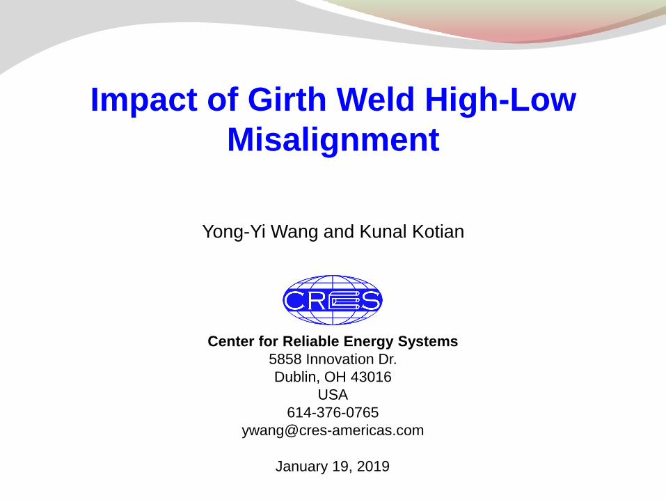
Copyright © CRES Center for Reliable Energy Systems 5858 Innovation Dr. Dublin, OH 43016 USA 614-376-0765 [email protected] Impact of Girth Weld High-Low Misalignment Yong-Yi Wang and Kunal Kotian January 19, 2019

Welcome message from author
This document is posted to help you gain knowledge. Please leave a comment to let me know what you think about it! Share it to your friends and learn new things together.
Transcript
Copyright © CRES
Center for Reliable Energy Systems
5858 Innovation Dr.
Dublin, OH 43016
USA
614-376-0765
Impact of Girth Weld High-Low
Misalignment
Yong-Yi Wang and Kunal Kotian
January 19, 2019

Copyright © CRES
Background and Incentives
Some newly constructed pipelines in the US experienced
Hydrostatic failures
In-service leaks soon after lines were put in service
PHMSA issued ADB-10-03 (March 18, 2010)
Girth weld quality issues were identified.
Some of the contributing factors
Improper transitioning
High-low misalignment
Improper welding practice and/or not following qualified welding procedure
Hydrogen-assisted cracking
High stresses acting on girth welds from improper pipe support and backfill in hilly terrains
A joint task group was formed between API 5L and 1104 committees.
Expected outcome
set “allowable misalignment”, and/or
Pipe dimensional tolerance
1/19/2016 2 Impact of Girth Weld High-Low Misalignment
Copyright © CRES
Background and Incentives
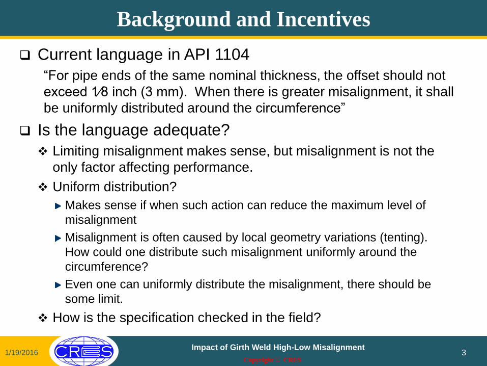
Current language in API 1104
“For pipe ends of the same nominal thickness, the offset should not
exceed 1⁄8 inch (3 mm). When there is greater misalignment, it shall
be uniformly distributed around the circumference”
Is the language adequate?
Limiting misalignment makes sense, but misalignment is not the
only factor affecting performance.
Uniform distribution?
Makes sense if when such action can reduce the maximum level of
misalignment
Misalignment is often caused by local geometry variations (tenting).
How could one distribute such misalignment uniformly around the
circumference?
Even one can uniformly distribute the misalignment, there should be
some limit.
How is the specification checked in the field?
1/19/2016 3
Impact of Girth Weld High-Low Misalignment
Copyright © CRES
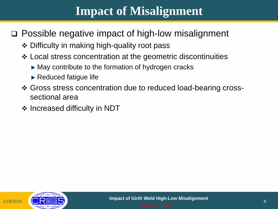
Impact of Misalignment
Possible negative impact of high-low misalignment
Difficulty in making high-quality root pass
Local stress concentration at the geometric discontinuities
May contribute to the formation of hydrogen cracks
Reduced fatigue life
Gross stress concentration due to reduced load-bearing cross-
sectional area
Increased difficulty in NDT
1/19/2016 4 Impact of Girth Weld High-Low Misalignment

Copyright © CRES
Phase I Welds
Two girth welds with intentionally made high levels of misalignment
Weld 1: 36” OD, 0.372” WT, Grade X70 Mechanized GMAW on an UOE pipe, girth welding consumable: ER70S-6
High-low misalignment between 0.0 and 2.1 mm (misalignment / WT = 0.00-0.22)
Weld 2: 24” OD, 0.500” WT, Grade X70 Manual SMAW on an ERW pipe, girth welding consumable: E8045-P2 H4R
High-low misalignment between 0.0 and 5.0 mm (misalignment / WT = 0.00-0.39)
1/19/2016 5 Impact of Girth Weld High-Low Misalignment
24” O.D. Girth Weld,
CWT # 10, 5 mm hi-lo
WT = 0.5”
Cross-weld region not polished or etched:
36” O.D. Girth Weld,
CWT # 9,
2 mm hi-lo
WT =
0.372”
Cross-weld region polished + etched:

Copyright © CRES
Observations from Phase I Tests
Weld 1 (mechanized GMAW)
The pipe “UTS” variation of approximately 5% was observed.
There is a dependence pipe UTS on o’clock position.
Weld strength mismatch ratio = ~1.05 (5% overmatching).
All “failures” of the cross-weld samples occurred in the base metal.
Weld 2 (manual SMAW)
Weld strength mismatch ratio = 0.95 (5% undermatching)
There is a load capacity reduction of 9.5% for misalignment up to
39% of wall thickness.
The iso-load capacity relation of CRES models captures the highest
load capacity reduction.
1/19/2016 Impact of Girth Weld High-Low Misalignment
6

Copyright © CRES
Phase 2 Welds
Four girth welds with intentionally made high levels of
misalignment
36” (914 mm) OD 0.531” (13.5 mm) WT X70 spiral pipe
Tie-in WPS
Root: E6010
Fills and cap: E8010 HP vertical up flux core using M300 bug
1/19/2016 7 Impact of Girth Weld High-Low Misalignment

Copyright © CRES
Phase 2 – Weld Macro & Hardness Traverse
1/19/2016 8 Impact of Girth Weld High-Low Misalignment
10 kg Vickers hardness traverse
Specimens from GW #55 & 58
tested
Weld #55 results
Pipe sides have similar hardness
WM ⁄ BM = 0.89
HAZ ⁄ BM ≈ 1
Weld #58 results
Pipe sides have dissimilar hardness
12% difference in hardness
WM ⁄ BM = 0.82 and 0.93
(two values for 2 pipe sides)
HAZ ⁄ BM ≈ 1
Copyright © CRES
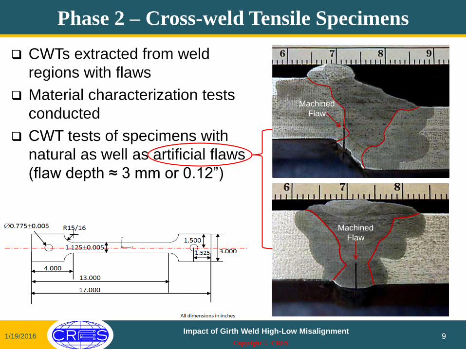
Phase 2 – Cross-weld Tensile Specimens
CWTs extracted from weld
regions with flaws
Material characterization tests
conducted
CWT tests of specimens with
natural as well as artificial flaws
(flaw depth ≈ 3 mm or 0.12”)
1/19/2016 9 Impact of Girth Weld High-Low Misalignment
Machined
Flaw
Machined
Flaw
Machined
Flaw
Machined
Flaw
Copyright © CRES
276
345
414
483
552
621
689
40
50
60
70
80
90
100
0 10 20 30 40 50 60 70
Ma
xim
um
str
es
s (
MP
a)
Ma
xim
um
str
es
s (
ks
i)
High-low misalignment (% WT)
Artificial Flaw, Weld Region Failure
Natural Flaw, Weld Region Failure
No Flaw, Weld Region Failure
CWTs, Failed in the Weld Region
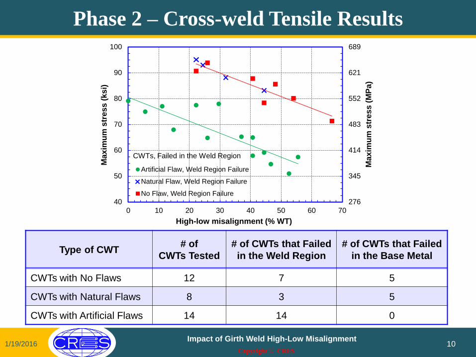
Phase 2 – Cross-weld Tensile Results
1/19/2016 10 Impact of Girth Weld High-Low Misalignment
Type of CWT # of
CWTs Tested
# of CWTs that Failed
in the Weld Region
# of CWTs that Failed
in the Base Metal
CWTs with No Flaws 12 7 5
CWTs with Natural Flaws 8 3 5
CWTs with Artificial Flaws 14 14 0
Copyright © CRES
Observations
The reduction of cross-weld stress capacity is modest even at
high levels of misalignment, when there is
a smooth transitioned and sufficiently filled weld profile,
no excessive weld strength undermatching, and
No large flaws
High levels of misalignment, by themselves, are not
necessarily an integrity concern, provided that
(1) under static loading,
(2) weld having sufficient toughness, and
(3) no large flaws.
1/19/2016 Impact of Girth Weld High-Low Misalignment
11
Copyright © CRES
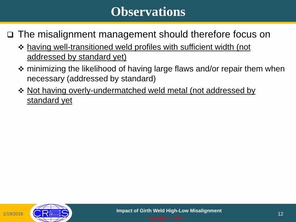
Observations
The misalignment management should therefore focus on
having well-transitioned weld profiles with sufficient width (not
addressed by standard yet)
minimizing the likelihood of having large flaws and/or repair them when
necessary (addressed by standard)
Not having overly-undermatched weld metal (not addressed by
standard yet
1/19/2016 Impact of Girth Weld High-Low Misalignment
12

Copyright © CRES
Thank You!
1/19/2016 Impact of Girth Weld High-Low Misalignment
13
Q&A
Related Documents