ISSN: 2277-9655 [Sivasankaraiah* et al., 6(2): February, 2017] Impact Factor: 4.116 IC™ Value: 3.00 CODEN: IJESS7 http: // www.ijesrt.com © International Journal of Engineering Sciences & Research Technology [413] IJESRT INTERNATIONAL JOURNAL OF ENGINEERING SCIENCES & RESEARCH TECHNOLOGY IMPACT CHARACTERISTICS OF POLYMER MATRIX COMPOSITES T. Sivasankaraiah*, V. kalyan Srinivas, C H.Umashankar, D. Goutham Reddy * Assistant professor, Dept. Of Aeronautical Engineering, VITA Hyderabad, India Ph: 9603734977 Assistant professor, Dept. Of Aeronautical Engineering, VITA Hyderabad, India Ph: 99704757650 Student, Dept. Of Aeronautical Engineering, VITA Hyderabad, India Ph: 9502785883 Student, Dept. Of Mechanical Engineering, VITA Hyderabad, India Ph: 9553549934 DOI: 10.5281/zenodo.291859 ABSTRACT In this paper, we study how the polymer composite materials will experience the impact strength at different combinations of matrix composition in different fiber orientations. The polymer matrix composite laminates were made into specimens of dimensions according to ASTM standards and are experimentally investigated by Izod & Charpy impact tests with and without notching the specimens. In the experimental program the laminates were prepared by matched die mould and filament winding techniques. The laminates were made with GFRP, CFRP, and Bi-directional glass fabrics are used as reinforcement, lapox L- 12, Araldite LY 556 as resins and lapox K-6, Araldite HT-972,Aradur 5200 as hardeners. The stacking sequences, of laminates are as follows [0/90/0/90], [+45/-45/+45/-45] and [90/-45/+45/0]. KEYWORDS: Glass fiber reinforced plastics, Carbon fiber reinforced plastics, filament winding. INTRODUCTION Composite material can be defined as a macroscopic combination of two are more materials that results in better properties than those of individual components used alone. Progresses in the field of materials science and technology haven birth to these fascinating and wonderful materials. Composites are heterogeneous in nature and are very versatile and can be tailor-made. Therefore, they can be a solution to the needs in the future. The matrix materials may be metallic, ceramic or polymeric in origin. These are well known materials which satisfy many of the traditional requirements. Despite the tremendous advantages that advanced composites have over metals in applications requiring high strength, stiffness, and low weight in applications where impact by foreign objects is a design consideration, the advantages inherent in composites are overshadowed by their poor response to impact loading. LITERATURE STUDY A considerable amount of literature has been written on the behavior of glass fiber composites exposed to impact energy covering different aspects of the topic. Dr. Donald F. Adams discusses the methods for impact testing of composites. The impact response of composite materials use were primarily reinforced with glass fibers, which performed well under impact loads. This soon proved not to be true for carbon fibers, which are relatively brittle. But since their static strength and stiffness properties were very attractive, development of carbon fiber reinforcements for structural applications continued. The Charpy impact testing for metals and plastics where a simple tensile failure could be induced at the notch root, the failure mode of composite materials was often complex. The mode of failure of the composite is inconsistent, and thus it is difficult to relate the measured absorbed energy of the Charpy specimen to that of an actual structural component. Thus, after considerable research, Charpy impact testing of composites was abandoned.

Welcome message from author
This document is posted to help you gain knowledge. Please leave a comment to let me know what you think about it! Share it to your friends and learn new things together.
Transcript
ISSN 2277-9655
[Sivasankaraiah et al 6(2) February 2017] Impact Factor 4116
ICtrade Value 300 CODEN IJESS7
http wwwijesrtcom copy International Journal of Engineering Sciences amp Research Technology
[413]
IJESRT INTERNATIONAL JOURNAL OF ENGINEERING SCIENCES amp RESEARCH
TECHNOLOGY
IMPACT CHARACTERISTICS OF POLYMER MATRIX COMPOSITES T Sivasankaraiah V kalyan Srinivas C HUmashankar D Goutham Reddy
Assistant professor Dept Of Aeronautical Engineering VITA Hyderabad India Ph 9603734977
Assistant professor Dept Of Aeronautical Engineering VITA Hyderabad India Ph 99704757650
Student Dept Of Aeronautical Engineering VITA Hyderabad India Ph 9502785883
Student Dept Of Mechanical Engineering VITA Hyderabad India Ph 9553549934
DOI 105281zenodo291859
ABSTRACT In this paper we study how the polymer composite materials will experience the impact strength at different
combinations of matrix composition in different fiber orientations The polymer matrix composite laminates were
made into specimens of dimensions according to ASTM standards and are experimentally investigated by Izod amp
Charpy impact tests with and without notching the specimens In the experimental program the laminates were
prepared by matched die mould and filament winding techniques
The laminates were made with GFRP CFRP and Bi-directional glass fabrics are used as reinforcement lapox L-
12 Araldite LY 556 as resins and lapox K-6 Araldite HT-972Aradur 5200 as hardeners The stacking sequences
of laminates are as follows [090090] [+45-45+45-45] and [90-45+450]
KEYWORDS Glass fiber reinforced plastics Carbon fiber reinforced plastics filament winding
INTRODUCTION Composite material can be defined as a macroscopic combination of two are more materials that results in better
properties than those of individual components used alone
Progresses in the field of materials science and technology haven birth to these fascinating and wonderful
materials Composites are heterogeneous in nature and are very versatile and can be tailor-made Therefore they
can be a solution to the needs in the future The matrix materials may be metallic ceramic or polymeric in origin
These are well known materials which satisfy many of the traditional requirements Despite the tremendous
advantages that advanced composites have over metals in applications requiring high strength stiffness and low
weight in applications where impact by foreign objects is a design consideration the advantages inherent in
composites are overshadowed by their poor response to impact loading
LITERATURE STUDY A considerable amount of literature has been written on the behavior of glass fiber composites exposed to impact
energy covering different aspects of the topic
Dr Donald F Adams discusses the methods for impact testing of composites The impact response of composite
materials use were primarily reinforced with glass fibers which performed well under impact loads This soon
proved not to be true for carbon fibers which are relatively brittle But since their static strength and stiffness
properties were very attractive development of carbon fiber reinforcements for structural applications continued
The Charpy impact testing for metals and plastics where a simple tensile failure could be induced at the notch
root the failure mode of composite materials was often complex The mode of failure of the composite is
inconsistent and thus it is difficult to relate the measured absorbed energy of the Charpy specimen to that of an
actual structural component Thus after considerable research Charpy impact testing of composites was
abandoned
ISSN 2277-9655
[Sivasankaraiah et al 6(2) February 2017] Impact Factor 4116
ICtrade Value 300 CODEN IJESS7
http wwwijesrtcom copy International Journal of Engineering Sciences amp Research Technology
[414]
Mr Amal AM Badawy studied determining of the impact behavior of glass fibers reinforced polyester (GFRP)
was experimentally investigated using notched Izod impact test specimen The experimental program was carried
out on unidirectional laminate of GFRP in directions 0 45and 90 in addition to cross-ply laminate (0900)s The
effect of fiber volume fraction test results showed that fiber volume fraction on impact strength of GFRP
composite depends on the parameter controlling the mode of failure ie matrix or fiber The failure characteristic
changed from fiber pull-out to fiber breakage with increasing the exposure temperature
Mahmood M Shokrieha Mohammad A Torabizadeh This paper demonstrates results of an experimental study on
glassepoxy laminated composites subjected to low velocity impact energy levels and low temperatures by a
Charpy device were experimentally investigated The configuration of laminates was quasi-isotropic Low
temperature and its weakening influence on the material properties including maximum absorbed energy elastic
energy maximum crack length and maximum delamination length are highlighted Moreover the effects of
geometry index and notch orientation are determined based on the test results
SELECTION OF MATERIALS E-Glass Fabric
Over 95 of the fabric used in reinforced plastics are glass fabric as they are inexpensive easy to manufacture
and possess high strength and stiffness with respect to the plastics with which they are reinforced
Their low density resistance to chemicals insulation capacity are other bonus characteristics although the one
major disadvantage in glass is that it is prone to break when subjected to high tensile stress for a long time
However it remains break-resistant at higher stress-levels in shorter time frames This property mitigates the
effective strength of glass especially when glass is expected to sustain loads for many months or years
continuously
Period of loading temperature moisture and other factors also dictate the tolerance levels of glass fibers and the
disadvantage is further compounded by the fact that the brittleness of glass does not make room for prior warning
before the anamorphic failure
But all this can be easily overlooked in view of the fact the wide range of glass fiber variety lend themselves
amicably to fabrication processes like matched die-molding filament winding lay-up and so on Glass fibres are
available in the form of mates tapes cloth continuous and chopped filaments roving and yarns
Addition of chemicals to silica sand while making glass yields different types of glasses
E-Glass or electrical grade glass was originally developed for standoff insulators for electrical wiring It was later
found to have excellent fibre forming capabilities and is now used almost exclusively as the reinforcing phase in
the material commonly known as fiber glass
The use of E-Glass as the reinforcement material in polymer matrix composites is extremely common Optimal
strength properties are gained when straight continuous fibers are aligned parallel in a single direction To
promote strength in other directions laminate structures can be constructed with continuous fibers aligned in
other directions
Glass fiber technical specifications
1 Nomenclature 13 MIL E GLASS FABRIC
2 Thickness mm 036
3 Width inch 40
4 Type of Weave 4 Harness-Satin
5 Construction
Warp Threadsinch 48
Weft Threadsinch 36
6 Weight per Sqmtr 456900 gms
7 Breaking Strength per 50 mm
Warp 361000 Kgs
Weft 274000 Kgs
ISSN 2277-9655
[Sivasankaraiah et al 6(2) February 2017] Impact Factor 4116
ICtrade Value 300 CODEN IJESS7
http wwwijesrtcom copy International Journal of Engineering Sciences amp Research Technology
[415]
Carbon fiber Technical specifications
A fiber manufactured by pyrolysis of organic precursor fibers in an inert atmosphere at extremely high
temperatures
Product Description100 recycled carbon fibers which have been purified by pyrolysis and milled to specified
lengths
Standard Filament Diameter 6 microns
Nominal Filament Length ~100 microns (01mm)
Tensile Strength gt3200 MPa
Electrical Resistance 16 x 10-3 Ωcm
Thermal Expansion Coefficient -01 (10-6 K-1)
Specific Gravity 18 gcmsup3
Resins
231 Bisphenol A epoxy resin (LAPOX-L12)
Lapox L12 is a liquid unmodified epoxy resin of medium viscosity which can be used with various hardeners for
making glass fiber reinforced composites Important epoxy resins are produced from combining epichlorohydrin
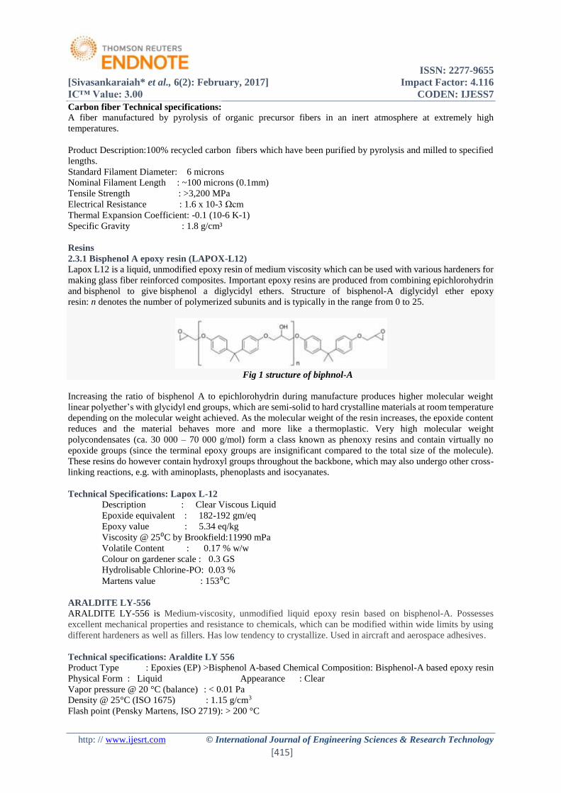
and bisphenol to give bisphenol a diglycidyl ethers Structure of bisphenol-A diglycidyl ether epoxy
resin n denotes the number of polymerized subunits and is typically in the range from 0 to 25
Fig 1 structure of biphnol-A
Increasing the ratio of bisphenol A to epichlorohydrin during manufacture produces higher molecular weight
linear polyetherrsquos with glycidyl end groups which are semi-solid to hard crystalline materials at room temperature
depending on the molecular weight achieved As the molecular weight of the resin increases the epoxide content
reduces and the material behaves more and more like a thermoplastic Very high molecular weight
polycondensates (ca 30 000 ndash 70 000 gmol) form a class known as phenoxy resins and contain virtually no
epoxide groups (since the terminal epoxy groups are insignificant compared to the total size of the molecule)
These resins do however contain hydroxyl groups throughout the backbone which may also undergo other cross-
linking reactions eg with aminoplasts phenoplasts and isocyanates
Technical Specifications Lapox L-12
Description Clear Viscous Liquid
Epoxide equivalent 182-192 gmeq
Epoxy value 534 eqkg
Viscosity 25⁰C by Brookfield11990 mPa
Volatile Content 017 ww
Colour on gardener scale 03 GS
Hydrolisable Chlorine-PO 003
Martens value 153⁰C
ARALDITE LY-556 ARALDITE LY-556 is Medium-viscosity unmodified liquid epoxy resin based on bisphenol-A Possesses
excellent mechanical properties and resistance to chemicals which can be modified within wide limits by using
different hardeners as well as fillers Has low tendency to crystallize Used in aircraft and aerospace adhesives
Technical specifications Araldite LY 556
Product Type Epoxies (EP) gtBisphenol A-based Chemical Composition Bisphenol-A based epoxy resin
Physical Form Liquid Appearance Clear
Vapor pressure 20 degC (balance) lt 001 Pa
Density 25degC (ISO 1675) 115 gcm3
Flash point (Pensky Martens ISO 2719) gt 200 degC
ISSN 2277-9655
[Sivasankaraiah et al 6(2) February 2017] Impact Factor 4116
ICtrade Value 300 CODEN IJESS7
http wwwijesrtcom copy International Journal of Engineering Sciences amp Research Technology
[416]
Color (Gardner ISO 4630) 2GS
Epoxy index (ISO 3001) 530 - 545 eqkg
Epoxy equivalent (ISO 3001) 183 - 189 geq
Viscosity 25 degC 10000 - 12000 mPa
Hardeners
LAPOX K-6
Hardener K6 is a low viscosity room temperature curing liquid hardener It is commonly employed for hand lay-
up applications Being rather reactive it gives a short pot life and rapid cure at normal ambient temperatures
Laminates can be subjected to operating temperatures of 1000 C
Technical Specifications hardener k-6
Visual appearance clear liquid
Colour on GARDENER SCALE 04 GS
Refractive index at 25⁰C 14951
Water content by KF 018 max
Shear strength 14Kgmmsup2
ARALDITE HT-972
Araldite is medium viscosity unmodified liquid epoxy resin based on Bisphenol Araldite hardener HT-972 is a
solid state hardener which upon heating turns into a low viscous fluid Glass fibre laminates are dimensionally
stable Glass fibre laminates are practically free from internal stress Excellent water resistance
Technical specifications HT 972
Physical state solid
Colour pale yellow
Odor pungent
Melting point 100⁰C (15min)
Flash point ˃18
Viscosity at 25⁰C Dynamic 10-20mPas
Density 097-099gcmsup3 [25⁰]
ARADUR 5200
Technical Specifications ARADUR 5200
Physical state liquid
Colour brown
Odor pungent
Boiling point 308⁰C (5864⁰F)
Flash point
Closed cup ˃120⁰C (˃248⁰F)
Open cup 168⁰C (3334⁰F)
Decomposition ˃200⁰C (˃392⁰F)
Vapour pressure ˂000013KPa (˂0000975mm Hg)
Specific gravity 102
Partition coefficient 117
Viscosity Dynamic 160 mPas (160cp)
Density 1gcmsup3 [20⁰(68⁰F)]
Pigment
A pigment is a material that changes the color of reflected or transmitted light as the result of wavelength-
selective absorption This physical process differs from fluorescence phosphorescence and other forms
of luminescence in which a material emits light Many materials selectively absorb certain wavelengths of light
Materials that humans have chosen and developed for use as pigments usually have special properties that make
them ideal for coloring other materials A pigment must have a high tinting strength relative to the materials it
colors It must be stable in solid form at ambient temperatures
ISSN 2277-9655
[Sivasankaraiah et al 6(2) February 2017] Impact Factor 4116
ICtrade Value 300 CODEN IJESS7
http wwwijesrtcom copy International Journal of Engineering Sciences amp Research Technology
[417]
For industrial applications as well as in the arts permanence and stability are desirable properties Pigments that
are not permanent are called fugitive Fugitive pigments fade over time or with exposure to light while some
eventually blacken
Pigments are used for coloring paint ink plastic fabric cosmetics food and other materials Most pigments used
in manufacturing and the visual arts are dry colorants usually ground into a fine powder This powder is added to
a binder (or vehicle) a relatively neutral or colorless material that suspends the pigment and gives the paint its
adhesion
A distinction is usually made between a pigment which is insoluble in its vehicle (resulting in a suspension) and
a dye which either is itself a liquid or is soluble in its vehicle (resulting in a solution) A colorant can act as either
a pigment or a dye depending on the vehicle involved In some cases a pigment can be manufactured from a dye
by precipitating a soluble dye with a metallic salt The resulting pigment is called a lake pigment The term
biological pigment is used for all colored substances independent of their solubility
SELECTION OF FABRICATION PROCESS Several factors should be considered before selecting the manufacturing process for a particular part
User requirements
Performance requirements
Total production volume
Production rate
Cost of production
Size of the production
Surface finish of the final product
Geometry of the product
Material
These are important for all manufacturing processes and even more so for composite materials Ideally structural
design of the product and design of the required manufacturing process should be completed using a concurrent
approach
Matched die mould process
Even though the method has been replaced with automated techniques the lay-up of pre impregnated material by
hand is the oldest and most common fabrication method for advanced composite structures Furthermore the basic
features of the method remain unchanged A pictorial essay showing each step in the hand lay-up of a flat
composite laminate is shown
Each step must follow in successive fashion in order to obtain a high-quality composite laminate after final
processing A description of these steps follows
A single layer of a laminated composite material is generally referred to as a ply or lamina It usually contains a
single layer of reinforcement unidirectional or multidirectional A single lamina is generally too thin to be directly
used in any engineering application Several lamina are bonded together to form a structure termed as laminate
Properties and orientation of the lamina in a laminate are chosen to meet the laminate design requirements
Properties of a laminate may be predicted by knowing the properties of its constituent lamina
EXPERIMENTAL WORK In this experimental work the laminates were with the following orientations
1 0-90⁰ (0-90⁰-0-90⁰-0-90⁰-0)
2 plusmn45 (45-45+45-45+45-45+45)
3 90plusmn450plusmn4590 (90-45+450+45-4590)
Manufacturing process
1 Preparation of mould
Here mould of dimensions 390mmx340mm is prepared and surface is cleaned with acetone and if there is any
imperfections the mould is rubbed with 0⁰emry paper to get the clean surface as shown in figure 41
ISSN 2277-9655
[Sivasankaraiah et al 6(2) February 2017] Impact Factor 4116
ICtrade Value 300 CODEN IJESS7
http wwwijesrtcom copy International Journal of Engineering Sciences amp Research Technology
[418]
2 Measuring of matrix for laminate as per equal weight ratio of matrix and reinforcement That is weight of
reinforcement for one laminate equals to weight of matrix
3 The fabric is laid on the workbench which is covered with polythene sheet and then marking is taken by using
required dimensions and orientations with help of templates as shown in figure 42
4 Bonding agent(epoxy resin) is applied to create bonding between layers This is usually accomplished by rollers
or brushes with an increasing use of roller type impregnators for forcing resin in to the fabric
5Cut the fabric into laminas as per marking and place on the mold before peel outing the polythene sheet Repeat
the same process for all laminas shown in figure 43
6 After closing the mold properly allow it for curing as per cure cycle
7 Extract the laminate gently and cut the specimens according to required dimensions as per ASTM standards
Fig 41 mold
Fig 42 application of matrix over fabric
Fig 43 applying of plies over mould by sequence
IMPACT TESTING PROCEDURE Impact tests are performed to asses shock absorbing capacity of materials subjected to suddenly applied loads
In Izod test the specimen is placed as lsquocantilever beamrsquo The specimens have V-shaped notch of 45deg U-shaped
notch is also common The notch is located on tension side of specimen during impact loading Depth of notch is
generally taken as t5 to t3 where lsquotrsquo is thickness of the specimen
machine specifications
Its specifications along-with their typical values are as follows
1 Impact capacity = 164joule
2 Least count of capacity (dial) scale= 2joule
3 Weight of striking hammer = 2179 kg
ISSN 2277-9655
[Sivasankaraiah et al 6(2) February 2017] Impact Factor 4116
ICtrade Value 300 CODEN IJESS7
http wwwijesrtcom copy International Journal of Engineering Sciences amp Research Technology
[419]
4 Swing diameter of hammer = 1600mm
5 Angle of hammer before striking = 90deg
6 Striking velocity of hammer = 56msec
7 Length of the pendulum = 0796m
8 Specimen size = 64x127x32 mm3
9 Type of notch = V-notch
10 Angle of notch = 45deg
11 Depth of notch = 2 mm
Testing procedure
Check that the pendulum machine has the specified velocity of impact and that it is in the correct range of absorbed
energy
Conduct a blank test and record the measured values of the total frictional loss Ensure that this energy loss does
not exceed the appropriate value as per the standard
1 Lift the hammer to an appropriate knife edge position and notch the energy stored in the hammer For
the standard Izod test the energy stored should be 164j
2 Locate the test specimen on the mc supports shown in fig 51
3 Release the hammer The hammer will break the piece and shoot up the other side of the specimen
4 Note the residual energy indicated on the scale by the hammer
5 Impact strength of the test specimen is the difference of the initial energy stored in hammer and the
residual energy
Calculation-
bull Notch impact strength = Absorb energy Effective cross section area
Impact Strength = Impact Energy (joules)
Cross section area (mm2)
Precautions- 1 The specimen should be prepared in proper dimensions
2 Take reading more frequently
3 Make the loose pointer in contact with the fixed pointer after setting the pendulum
4 Do not stand in front of swinging hammer or releasing hammer
5 Place the specimen in proper position
figure 51 izod test rig
ISSN 2277-9655
[Sivasankaraiah et al 6(2) February 2017] Impact Factor 4116
ICtrade Value 300 CODEN IJESS7
http wwwijesrtcom copy International Journal of Engineering Sciences amp Research Technology
[420]
TEST RESULT AND DISCUSSIONS Glass fabric with lapox -L-12 and K-6 as matrix in (0900 ) (plusmn45) (090plusmn45090) orientations
Table 61 glass fabric (0-90)
figure 61
In (090) orientation of glass fabric with Lapox and K-6 exhibits good impact characteristics in un notched
conditions
whereas with the same matrix and reinforcement but with orientation of fiber is in (plusmn45) is performing better
impact result as 126 joules than (090plusmn45090) as 91 joule in izod
NOTCHEDREV
NOTCHEDUN
NOTCHED
IZOD 49 62 72
CHARPY 318 357
49 62 72
318357
05
10152025303540
JOU
LES
GLASS FABRIC+L-12+K-6
(090)
IZOD CHARPY
IZOD TEST-(090) GLASS FABRIC( L-12 RESIN + K-6 HARDNER)
SNO NOTCHED SNO REV NOTCHED SNO UN NOTCEHD
impact
energy
(joules)
impact
strength
(jmmsup2)
impact
energy
(joules)
impact
strength
(jmmsup2)
impact
energy
(joules)
impact
strength
(jmmsup2)
cross
sectional
area
(mmsup2)
1 6 014764 1 4 0098425 1 6 014764 4064
2 5 012303 2 6 0147638 2 6 014764 4064
3 4 009843 3 8 019685 3 8 019685 4064
4 4 009843 4 8 019685 4 6 014764 4064
5 4 009843 5 6 0147638 5 7 017224 4064
6 5 012303 6 6 0147638 6 8 019685 4064
7 4 009843 7 6 0147638 7 8 019685 4064
8 5 012303 8 6 0147638 8 8 019685 4064
9 4 009843 9 6 0147638 9 7 017224 4064
10 8 019685 10 6 0147638 10 8 019685 4064
Average 49 01206 62 015256 72 01772
ISSN 2277-9655
[Sivasankaraiah et al 6(2) February 2017] Impact Factor 4116
ICtrade Value 300 CODEN IJESS7
http wwwijesrtcom copy International Journal of Engineering Sciences amp Research Technology
[421]
figure 62
4All fibers are oriented to 450 to pendulum in plusmn45 orientation this helps to absorb more impact energy and the
same reason this orientation absorbs less in charpy test compared to (090)
62 Carbon fiber with lapox -L-12 and Aradur 5200 as matrix in (090plusmn45090) orientation
Table 62 carbon fibre (090plusmn45090)
62 Carbon fiber with lapox -L-12 and Aradur 5200 as matrix in (plusmn45) (090plusmn45090) orientations
1 Carbon fiber with Aradur 5200 hardener giving good izod impact results in (plusmn45) orientation than the
(090plusmn45090) and (090)
2 In (090) fiber orientation both glass and carbon fiber performing good charpy impact results
3 The izod impact characteristics carbon with aradur 5200 hardener is exhibiting approximately same
results when fiber oriented in ( 090plusmn45090) and ( plusmn45) This is because fibers oriented in plusmn45 will
give great shear strength
4 Where as in the case of charpy the number of fibers which are oriented in (090) will gives better results
than (090plusmn45090) (plusmn45)
NOTCHEDREV
NOTCHEDUN
NOTCHED
IZOD 74 104 126
CHARPY 232 29
74104
126
232
29
0
5
10
15
20
25
30
35
JOU
LES
GLASS FABRIC+L-12+K-6(plusmn45)
IZOD CHARPY
IZOD TEST-COMBINATIONAL CARBON FIBER( L-12 + ARADUR 5200)
SNO NOTCHED SNO REV NOTCHED SNO UN NOTCEHD
impact
energy
(joules)
impact
strength
(jmmsup2)
impact
energy
(joules)
impact
strength
(jmmsup2)
impact
energy
(joules)
impact
strength
(jmmsup2)
cross
sectional
area
(mmsup2)
1 10 024606 1 14 0344488 1 13 031988 4064
2 14 034449 2 12 0295276 2 12 029528 4064
3 10 024606 3 12 0295276 3 15 036909 4064
4 12 029528 4 12 0295276 4 18 044291 4064
5 12 029528 5 13 0319882 5 15 036909 4064
6 11 027067 6 12 0295276 6 15 036909 4064
7 12 029528 7 10 0246063 7 15 036909 4064
8 13 031988 8 10 0246063 8 14 034449 4064
9 13 031988 9 12 0295276 9 15 036909 4064
10 12 029528 10 12 0295276 10 8 019685 4064
Average 119 024606 119 029281 14 03445
ISSN 2277-9655
[Sivasankaraiah et al 6(2) February 2017] Impact Factor 4116
ICtrade Value 300 CODEN IJESS7
http wwwijesrtcom copy International Journal of Engineering Sciences amp Research Technology
[422]
Table 63 carbon fiber (plusmn45)
figure 63
Glass fiber with lapox -L-12 and Aradur 5200 as matrix in (plusmn45) (090plusmn45090) orientations
Glass fiber with Lapox L-12 and aradur 5200 combination performing good impact results in izod (1333joules)
than glass fabric with the same matrix composition(126 joules) in plusmn45 fiber orientation and in (090plusmn45090)
fiber orientation also glass fiber shows improvement over fabric shown in figure 64
figure 64
NOTCHEDREV
NOTCHEDUN
NOTCHED
IZOD 119 119 14
CHARPY 229 253
119 11914
229253
0
5
10
15
20
25
30
JOU
LES
CARBON FIBER +L12+ARADUR
5200+(090plusmn45090)
IZOD CHARPY
NOTCHEDREV
NOTCHEDUN
NOTCHED
IZOD 1133 1166 1333
CHARPY 23 283
1133 1166 1333
23283
05
1015202530
JOU
LES
GLASS FIBER +L-12+aradur 5200+
(plusmn45)
IZOD CHARPY
ISSN 2277-9655
[Sivasankaraiah et al 6(2) February 2017] Impact Factor 4116
ICtrade Value 300 CODEN IJESS7
http wwwijesrtcom copy International Journal of Engineering Sciences amp Research Technology
[423]
CONCLUSIONS 1 In the present investigation on impact characteristics of polymer matrix composites depends upon
reinforcement orientation of the reinforcement and matrix composition
2 The characterization was carried among three reinforcements glass fabric glass fiber carbon fiber and
three orientations that is (090)(090plusmn45090) (plusmn45) with different matrix systems (lapox L-12+ K-
6) (lapox L-12+ aradur 5200)
3 Carbon fiber with (plusmn45) orientation in composition of Lapox L-12+ Aradur 5200 giving best in both izod
and chary impact characteristics
4 Glass fiber in (plusmn45) orientation in composition of Lapox L-12+ Aradur 5200 giving approximate results
with carbon fiber in both izod and chary impact characteristics
5 Glass fabric with (lapox L-12+ K-6) in (090) orientation giving lowest izod impact result
6 In (090plusmn45090) orientation the reinforcement giving intermediate results of reinforcement in (090)
(plusmn45) in respective matrix composition
REFERENCES [1] httpwikipediaorgwikiinteoduction to composite materials
[2] httpenwikipediaorgwikiclassification of composite materials
[3] httpenwikipediaorgwikitypes of fibre reinforcements
[4] httpenwikipediaorgwikitypes of matrix materials
ISSN 2277-9655
[Sivasankaraiah et al 6(2) February 2017] Impact Factor 4116
ICtrade Value 300 CODEN IJESS7
http wwwijesrtcom copy International Journal of Engineering Sciences amp Research Technology
[414]
Mr Amal AM Badawy studied determining of the impact behavior of glass fibers reinforced polyester (GFRP)
was experimentally investigated using notched Izod impact test specimen The experimental program was carried
out on unidirectional laminate of GFRP in directions 0 45and 90 in addition to cross-ply laminate (0900)s The
effect of fiber volume fraction test results showed that fiber volume fraction on impact strength of GFRP
composite depends on the parameter controlling the mode of failure ie matrix or fiber The failure characteristic
changed from fiber pull-out to fiber breakage with increasing the exposure temperature
Mahmood M Shokrieha Mohammad A Torabizadeh This paper demonstrates results of an experimental study on
glassepoxy laminated composites subjected to low velocity impact energy levels and low temperatures by a
Charpy device were experimentally investigated The configuration of laminates was quasi-isotropic Low
temperature and its weakening influence on the material properties including maximum absorbed energy elastic
energy maximum crack length and maximum delamination length are highlighted Moreover the effects of
geometry index and notch orientation are determined based on the test results
SELECTION OF MATERIALS E-Glass Fabric
Over 95 of the fabric used in reinforced plastics are glass fabric as they are inexpensive easy to manufacture
and possess high strength and stiffness with respect to the plastics with which they are reinforced
Their low density resistance to chemicals insulation capacity are other bonus characteristics although the one
major disadvantage in glass is that it is prone to break when subjected to high tensile stress for a long time
However it remains break-resistant at higher stress-levels in shorter time frames This property mitigates the
effective strength of glass especially when glass is expected to sustain loads for many months or years
continuously
Period of loading temperature moisture and other factors also dictate the tolerance levels of glass fibers and the
disadvantage is further compounded by the fact that the brittleness of glass does not make room for prior warning
before the anamorphic failure
But all this can be easily overlooked in view of the fact the wide range of glass fiber variety lend themselves
amicably to fabrication processes like matched die-molding filament winding lay-up and so on Glass fibres are
available in the form of mates tapes cloth continuous and chopped filaments roving and yarns
Addition of chemicals to silica sand while making glass yields different types of glasses
E-Glass or electrical grade glass was originally developed for standoff insulators for electrical wiring It was later
found to have excellent fibre forming capabilities and is now used almost exclusively as the reinforcing phase in
the material commonly known as fiber glass
The use of E-Glass as the reinforcement material in polymer matrix composites is extremely common Optimal
strength properties are gained when straight continuous fibers are aligned parallel in a single direction To
promote strength in other directions laminate structures can be constructed with continuous fibers aligned in
other directions
Glass fiber technical specifications
1 Nomenclature 13 MIL E GLASS FABRIC
2 Thickness mm 036
3 Width inch 40
4 Type of Weave 4 Harness-Satin
5 Construction
Warp Threadsinch 48
Weft Threadsinch 36
6 Weight per Sqmtr 456900 gms
7 Breaking Strength per 50 mm
Warp 361000 Kgs
Weft 274000 Kgs
ISSN 2277-9655
[Sivasankaraiah et al 6(2) February 2017] Impact Factor 4116
ICtrade Value 300 CODEN IJESS7
http wwwijesrtcom copy International Journal of Engineering Sciences amp Research Technology
[415]
Carbon fiber Technical specifications
A fiber manufactured by pyrolysis of organic precursor fibers in an inert atmosphere at extremely high
temperatures
Product Description100 recycled carbon fibers which have been purified by pyrolysis and milled to specified
lengths
Standard Filament Diameter 6 microns
Nominal Filament Length ~100 microns (01mm)
Tensile Strength gt3200 MPa
Electrical Resistance 16 x 10-3 Ωcm
Thermal Expansion Coefficient -01 (10-6 K-1)
Specific Gravity 18 gcmsup3
Resins
231 Bisphenol A epoxy resin (LAPOX-L12)
Lapox L12 is a liquid unmodified epoxy resin of medium viscosity which can be used with various hardeners for
making glass fiber reinforced composites Important epoxy resins are produced from combining epichlorohydrin
and bisphenol to give bisphenol a diglycidyl ethers Structure of bisphenol-A diglycidyl ether epoxy
resin n denotes the number of polymerized subunits and is typically in the range from 0 to 25
Fig 1 structure of biphnol-A
Increasing the ratio of bisphenol A to epichlorohydrin during manufacture produces higher molecular weight
linear polyetherrsquos with glycidyl end groups which are semi-solid to hard crystalline materials at room temperature
depending on the molecular weight achieved As the molecular weight of the resin increases the epoxide content
reduces and the material behaves more and more like a thermoplastic Very high molecular weight
polycondensates (ca 30 000 ndash 70 000 gmol) form a class known as phenoxy resins and contain virtually no
epoxide groups (since the terminal epoxy groups are insignificant compared to the total size of the molecule)
These resins do however contain hydroxyl groups throughout the backbone which may also undergo other cross-
linking reactions eg with aminoplasts phenoplasts and isocyanates
Technical Specifications Lapox L-12
Description Clear Viscous Liquid
Epoxide equivalent 182-192 gmeq
Epoxy value 534 eqkg
Viscosity 25⁰C by Brookfield11990 mPa
Volatile Content 017 ww
Colour on gardener scale 03 GS
Hydrolisable Chlorine-PO 003
Martens value 153⁰C
ARALDITE LY-556 ARALDITE LY-556 is Medium-viscosity unmodified liquid epoxy resin based on bisphenol-A Possesses
excellent mechanical properties and resistance to chemicals which can be modified within wide limits by using
different hardeners as well as fillers Has low tendency to crystallize Used in aircraft and aerospace adhesives
Technical specifications Araldite LY 556
Product Type Epoxies (EP) gtBisphenol A-based Chemical Composition Bisphenol-A based epoxy resin
Physical Form Liquid Appearance Clear
Vapor pressure 20 degC (balance) lt 001 Pa
Density 25degC (ISO 1675) 115 gcm3
Flash point (Pensky Martens ISO 2719) gt 200 degC
ISSN 2277-9655
[Sivasankaraiah et al 6(2) February 2017] Impact Factor 4116
ICtrade Value 300 CODEN IJESS7
http wwwijesrtcom copy International Journal of Engineering Sciences amp Research Technology
[416]
Color (Gardner ISO 4630) 2GS
Epoxy index (ISO 3001) 530 - 545 eqkg
Epoxy equivalent (ISO 3001) 183 - 189 geq
Viscosity 25 degC 10000 - 12000 mPa
Hardeners
LAPOX K-6
Hardener K6 is a low viscosity room temperature curing liquid hardener It is commonly employed for hand lay-
up applications Being rather reactive it gives a short pot life and rapid cure at normal ambient temperatures
Laminates can be subjected to operating temperatures of 1000 C
Technical Specifications hardener k-6
Visual appearance clear liquid
Colour on GARDENER SCALE 04 GS
Refractive index at 25⁰C 14951
Water content by KF 018 max
Shear strength 14Kgmmsup2
ARALDITE HT-972
Araldite is medium viscosity unmodified liquid epoxy resin based on Bisphenol Araldite hardener HT-972 is a
solid state hardener which upon heating turns into a low viscous fluid Glass fibre laminates are dimensionally
stable Glass fibre laminates are practically free from internal stress Excellent water resistance
Technical specifications HT 972
Physical state solid
Colour pale yellow
Odor pungent
Melting point 100⁰C (15min)
Flash point ˃18
Viscosity at 25⁰C Dynamic 10-20mPas
Density 097-099gcmsup3 [25⁰]
ARADUR 5200
Technical Specifications ARADUR 5200
Physical state liquid
Colour brown
Odor pungent
Boiling point 308⁰C (5864⁰F)
Flash point
Closed cup ˃120⁰C (˃248⁰F)
Open cup 168⁰C (3334⁰F)
Decomposition ˃200⁰C (˃392⁰F)
Vapour pressure ˂000013KPa (˂0000975mm Hg)
Specific gravity 102
Partition coefficient 117
Viscosity Dynamic 160 mPas (160cp)
Density 1gcmsup3 [20⁰(68⁰F)]
Pigment
A pigment is a material that changes the color of reflected or transmitted light as the result of wavelength-
selective absorption This physical process differs from fluorescence phosphorescence and other forms
of luminescence in which a material emits light Many materials selectively absorb certain wavelengths of light
Materials that humans have chosen and developed for use as pigments usually have special properties that make
them ideal for coloring other materials A pigment must have a high tinting strength relative to the materials it
colors It must be stable in solid form at ambient temperatures
ISSN 2277-9655
[Sivasankaraiah et al 6(2) February 2017] Impact Factor 4116
ICtrade Value 300 CODEN IJESS7
http wwwijesrtcom copy International Journal of Engineering Sciences amp Research Technology
[417]
For industrial applications as well as in the arts permanence and stability are desirable properties Pigments that
are not permanent are called fugitive Fugitive pigments fade over time or with exposure to light while some
eventually blacken
Pigments are used for coloring paint ink plastic fabric cosmetics food and other materials Most pigments used
in manufacturing and the visual arts are dry colorants usually ground into a fine powder This powder is added to
a binder (or vehicle) a relatively neutral or colorless material that suspends the pigment and gives the paint its
adhesion
A distinction is usually made between a pigment which is insoluble in its vehicle (resulting in a suspension) and
a dye which either is itself a liquid or is soluble in its vehicle (resulting in a solution) A colorant can act as either
a pigment or a dye depending on the vehicle involved In some cases a pigment can be manufactured from a dye
by precipitating a soluble dye with a metallic salt The resulting pigment is called a lake pigment The term
biological pigment is used for all colored substances independent of their solubility
SELECTION OF FABRICATION PROCESS Several factors should be considered before selecting the manufacturing process for a particular part
User requirements
Performance requirements
Total production volume
Production rate
Cost of production
Size of the production
Surface finish of the final product
Geometry of the product
Material
These are important for all manufacturing processes and even more so for composite materials Ideally structural
design of the product and design of the required manufacturing process should be completed using a concurrent
approach
Matched die mould process
Even though the method has been replaced with automated techniques the lay-up of pre impregnated material by
hand is the oldest and most common fabrication method for advanced composite structures Furthermore the basic
features of the method remain unchanged A pictorial essay showing each step in the hand lay-up of a flat
composite laminate is shown
Each step must follow in successive fashion in order to obtain a high-quality composite laminate after final
processing A description of these steps follows
A single layer of a laminated composite material is generally referred to as a ply or lamina It usually contains a
single layer of reinforcement unidirectional or multidirectional A single lamina is generally too thin to be directly
used in any engineering application Several lamina are bonded together to form a structure termed as laminate
Properties and orientation of the lamina in a laminate are chosen to meet the laminate design requirements
Properties of a laminate may be predicted by knowing the properties of its constituent lamina
EXPERIMENTAL WORK In this experimental work the laminates were with the following orientations
1 0-90⁰ (0-90⁰-0-90⁰-0-90⁰-0)
2 plusmn45 (45-45+45-45+45-45+45)
3 90plusmn450plusmn4590 (90-45+450+45-4590)
Manufacturing process
1 Preparation of mould
Here mould of dimensions 390mmx340mm is prepared and surface is cleaned with acetone and if there is any
imperfections the mould is rubbed with 0⁰emry paper to get the clean surface as shown in figure 41
ISSN 2277-9655
[Sivasankaraiah et al 6(2) February 2017] Impact Factor 4116
ICtrade Value 300 CODEN IJESS7
http wwwijesrtcom copy International Journal of Engineering Sciences amp Research Technology
[418]
2 Measuring of matrix for laminate as per equal weight ratio of matrix and reinforcement That is weight of
reinforcement for one laminate equals to weight of matrix
3 The fabric is laid on the workbench which is covered with polythene sheet and then marking is taken by using
required dimensions and orientations with help of templates as shown in figure 42
4 Bonding agent(epoxy resin) is applied to create bonding between layers This is usually accomplished by rollers
or brushes with an increasing use of roller type impregnators for forcing resin in to the fabric
5Cut the fabric into laminas as per marking and place on the mold before peel outing the polythene sheet Repeat
the same process for all laminas shown in figure 43
6 After closing the mold properly allow it for curing as per cure cycle
7 Extract the laminate gently and cut the specimens according to required dimensions as per ASTM standards
Fig 41 mold
Fig 42 application of matrix over fabric
Fig 43 applying of plies over mould by sequence
IMPACT TESTING PROCEDURE Impact tests are performed to asses shock absorbing capacity of materials subjected to suddenly applied loads
In Izod test the specimen is placed as lsquocantilever beamrsquo The specimens have V-shaped notch of 45deg U-shaped
notch is also common The notch is located on tension side of specimen during impact loading Depth of notch is
generally taken as t5 to t3 where lsquotrsquo is thickness of the specimen
machine specifications
Its specifications along-with their typical values are as follows
1 Impact capacity = 164joule
2 Least count of capacity (dial) scale= 2joule
3 Weight of striking hammer = 2179 kg
ISSN 2277-9655
[Sivasankaraiah et al 6(2) February 2017] Impact Factor 4116
ICtrade Value 300 CODEN IJESS7
http wwwijesrtcom copy International Journal of Engineering Sciences amp Research Technology
[419]
4 Swing diameter of hammer = 1600mm
5 Angle of hammer before striking = 90deg
6 Striking velocity of hammer = 56msec
7 Length of the pendulum = 0796m
8 Specimen size = 64x127x32 mm3
9 Type of notch = V-notch
10 Angle of notch = 45deg
11 Depth of notch = 2 mm
Testing procedure
Check that the pendulum machine has the specified velocity of impact and that it is in the correct range of absorbed
energy
Conduct a blank test and record the measured values of the total frictional loss Ensure that this energy loss does
not exceed the appropriate value as per the standard
1 Lift the hammer to an appropriate knife edge position and notch the energy stored in the hammer For
the standard Izod test the energy stored should be 164j
2 Locate the test specimen on the mc supports shown in fig 51
3 Release the hammer The hammer will break the piece and shoot up the other side of the specimen
4 Note the residual energy indicated on the scale by the hammer
5 Impact strength of the test specimen is the difference of the initial energy stored in hammer and the
residual energy
Calculation-
bull Notch impact strength = Absorb energy Effective cross section area
Impact Strength = Impact Energy (joules)
Cross section area (mm2)
Precautions- 1 The specimen should be prepared in proper dimensions
2 Take reading more frequently
3 Make the loose pointer in contact with the fixed pointer after setting the pendulum
4 Do not stand in front of swinging hammer or releasing hammer
5 Place the specimen in proper position
figure 51 izod test rig
ISSN 2277-9655
[Sivasankaraiah et al 6(2) February 2017] Impact Factor 4116
ICtrade Value 300 CODEN IJESS7
http wwwijesrtcom copy International Journal of Engineering Sciences amp Research Technology
[420]
TEST RESULT AND DISCUSSIONS Glass fabric with lapox -L-12 and K-6 as matrix in (0900 ) (plusmn45) (090plusmn45090) orientations
Table 61 glass fabric (0-90)
figure 61
In (090) orientation of glass fabric with Lapox and K-6 exhibits good impact characteristics in un notched
conditions
whereas with the same matrix and reinforcement but with orientation of fiber is in (plusmn45) is performing better
impact result as 126 joules than (090plusmn45090) as 91 joule in izod
NOTCHEDREV
NOTCHEDUN
NOTCHED
IZOD 49 62 72
CHARPY 318 357
49 62 72
318357
05
10152025303540
JOU
LES
GLASS FABRIC+L-12+K-6
(090)
IZOD CHARPY
IZOD TEST-(090) GLASS FABRIC( L-12 RESIN + K-6 HARDNER)
SNO NOTCHED SNO REV NOTCHED SNO UN NOTCEHD
impact
energy
(joules)
impact
strength
(jmmsup2)
impact
energy
(joules)
impact
strength
(jmmsup2)
impact
energy
(joules)
impact
strength
(jmmsup2)
cross
sectional
area
(mmsup2)
1 6 014764 1 4 0098425 1 6 014764 4064
2 5 012303 2 6 0147638 2 6 014764 4064
3 4 009843 3 8 019685 3 8 019685 4064
4 4 009843 4 8 019685 4 6 014764 4064
5 4 009843 5 6 0147638 5 7 017224 4064
6 5 012303 6 6 0147638 6 8 019685 4064
7 4 009843 7 6 0147638 7 8 019685 4064
8 5 012303 8 6 0147638 8 8 019685 4064
9 4 009843 9 6 0147638 9 7 017224 4064
10 8 019685 10 6 0147638 10 8 019685 4064
Average 49 01206 62 015256 72 01772
ISSN 2277-9655
[Sivasankaraiah et al 6(2) February 2017] Impact Factor 4116
ICtrade Value 300 CODEN IJESS7
http wwwijesrtcom copy International Journal of Engineering Sciences amp Research Technology
[421]
figure 62
4All fibers are oriented to 450 to pendulum in plusmn45 orientation this helps to absorb more impact energy and the
same reason this orientation absorbs less in charpy test compared to (090)
62 Carbon fiber with lapox -L-12 and Aradur 5200 as matrix in (090plusmn45090) orientation
Table 62 carbon fibre (090plusmn45090)
62 Carbon fiber with lapox -L-12 and Aradur 5200 as matrix in (plusmn45) (090plusmn45090) orientations
1 Carbon fiber with Aradur 5200 hardener giving good izod impact results in (plusmn45) orientation than the
(090plusmn45090) and (090)
2 In (090) fiber orientation both glass and carbon fiber performing good charpy impact results
3 The izod impact characteristics carbon with aradur 5200 hardener is exhibiting approximately same
results when fiber oriented in ( 090plusmn45090) and ( plusmn45) This is because fibers oriented in plusmn45 will
give great shear strength
4 Where as in the case of charpy the number of fibers which are oriented in (090) will gives better results
than (090plusmn45090) (plusmn45)
NOTCHEDREV
NOTCHEDUN
NOTCHED
IZOD 74 104 126
CHARPY 232 29
74104
126
232
29
0
5
10
15
20
25
30
35
JOU
LES
GLASS FABRIC+L-12+K-6(plusmn45)
IZOD CHARPY
IZOD TEST-COMBINATIONAL CARBON FIBER( L-12 + ARADUR 5200)
SNO NOTCHED SNO REV NOTCHED SNO UN NOTCEHD
impact
energy
(joules)
impact
strength
(jmmsup2)
impact
energy
(joules)
impact
strength
(jmmsup2)
impact
energy
(joules)
impact
strength
(jmmsup2)
cross
sectional
area
(mmsup2)
1 10 024606 1 14 0344488 1 13 031988 4064
2 14 034449 2 12 0295276 2 12 029528 4064
3 10 024606 3 12 0295276 3 15 036909 4064
4 12 029528 4 12 0295276 4 18 044291 4064
5 12 029528 5 13 0319882 5 15 036909 4064
6 11 027067 6 12 0295276 6 15 036909 4064
7 12 029528 7 10 0246063 7 15 036909 4064
8 13 031988 8 10 0246063 8 14 034449 4064
9 13 031988 9 12 0295276 9 15 036909 4064
10 12 029528 10 12 0295276 10 8 019685 4064
Average 119 024606 119 029281 14 03445
ISSN 2277-9655
[Sivasankaraiah et al 6(2) February 2017] Impact Factor 4116
ICtrade Value 300 CODEN IJESS7
http wwwijesrtcom copy International Journal of Engineering Sciences amp Research Technology
[422]
Table 63 carbon fiber (plusmn45)
figure 63
Glass fiber with lapox -L-12 and Aradur 5200 as matrix in (plusmn45) (090plusmn45090) orientations
Glass fiber with Lapox L-12 and aradur 5200 combination performing good impact results in izod (1333joules)
than glass fabric with the same matrix composition(126 joules) in plusmn45 fiber orientation and in (090plusmn45090)
fiber orientation also glass fiber shows improvement over fabric shown in figure 64
figure 64
NOTCHEDREV
NOTCHEDUN
NOTCHED
IZOD 119 119 14
CHARPY 229 253
119 11914
229253
0
5
10
15
20
25
30
JOU
LES
CARBON FIBER +L12+ARADUR
5200+(090plusmn45090)
IZOD CHARPY
NOTCHEDREV
NOTCHEDUN
NOTCHED
IZOD 1133 1166 1333
CHARPY 23 283
1133 1166 1333
23283
05
1015202530
JOU
LES
GLASS FIBER +L-12+aradur 5200+
(plusmn45)
IZOD CHARPY
ISSN 2277-9655
[Sivasankaraiah et al 6(2) February 2017] Impact Factor 4116
ICtrade Value 300 CODEN IJESS7
http wwwijesrtcom copy International Journal of Engineering Sciences amp Research Technology
[423]
CONCLUSIONS 1 In the present investigation on impact characteristics of polymer matrix composites depends upon
reinforcement orientation of the reinforcement and matrix composition
2 The characterization was carried among three reinforcements glass fabric glass fiber carbon fiber and
three orientations that is (090)(090plusmn45090) (plusmn45) with different matrix systems (lapox L-12+ K-
6) (lapox L-12+ aradur 5200)
3 Carbon fiber with (plusmn45) orientation in composition of Lapox L-12+ Aradur 5200 giving best in both izod
and chary impact characteristics
4 Glass fiber in (plusmn45) orientation in composition of Lapox L-12+ Aradur 5200 giving approximate results
with carbon fiber in both izod and chary impact characteristics
5 Glass fabric with (lapox L-12+ K-6) in (090) orientation giving lowest izod impact result
6 In (090plusmn45090) orientation the reinforcement giving intermediate results of reinforcement in (090)
(plusmn45) in respective matrix composition
REFERENCES [1] httpwikipediaorgwikiinteoduction to composite materials
[2] httpenwikipediaorgwikiclassification of composite materials
[3] httpenwikipediaorgwikitypes of fibre reinforcements
[4] httpenwikipediaorgwikitypes of matrix materials
ISSN 2277-9655
[Sivasankaraiah et al 6(2) February 2017] Impact Factor 4116
ICtrade Value 300 CODEN IJESS7
http wwwijesrtcom copy International Journal of Engineering Sciences amp Research Technology
[416]
Color (Gardner ISO 4630) 2GS
Epoxy index (ISO 3001) 530 - 545 eqkg
Epoxy equivalent (ISO 3001) 183 - 189 geq
Viscosity 25 degC 10000 - 12000 mPa
Hardeners
LAPOX K-6
Hardener K6 is a low viscosity room temperature curing liquid hardener It is commonly employed for hand lay-
up applications Being rather reactive it gives a short pot life and rapid cure at normal ambient temperatures
Laminates can be subjected to operating temperatures of 1000 C
Technical Specifications hardener k-6
Visual appearance clear liquid
Colour on GARDENER SCALE 04 GS
Refractive index at 25⁰C 14951
Water content by KF 018 max
Shear strength 14Kgmmsup2
ARALDITE HT-972
Araldite is medium viscosity unmodified liquid epoxy resin based on Bisphenol Araldite hardener HT-972 is a
solid state hardener which upon heating turns into a low viscous fluid Glass fibre laminates are dimensionally
stable Glass fibre laminates are practically free from internal stress Excellent water resistance
Technical specifications HT 972
Physical state solid
Colour pale yellow
Odor pungent
Melting point 100⁰C (15min)
Flash point ˃18
Viscosity at 25⁰C Dynamic 10-20mPas
Density 097-099gcmsup3 [25⁰]
ARADUR 5200
Technical Specifications ARADUR 5200
Physical state liquid
Colour brown
Odor pungent
Boiling point 308⁰C (5864⁰F)
Flash point
Closed cup ˃120⁰C (˃248⁰F)
Open cup 168⁰C (3334⁰F)
Decomposition ˃200⁰C (˃392⁰F)
Vapour pressure ˂000013KPa (˂0000975mm Hg)
Specific gravity 102
Partition coefficient 117
Viscosity Dynamic 160 mPas (160cp)
Density 1gcmsup3 [20⁰(68⁰F)]
Pigment
A pigment is a material that changes the color of reflected or transmitted light as the result of wavelength-
selective absorption This physical process differs from fluorescence phosphorescence and other forms
of luminescence in which a material emits light Many materials selectively absorb certain wavelengths of light
Materials that humans have chosen and developed for use as pigments usually have special properties that make
them ideal for coloring other materials A pigment must have a high tinting strength relative to the materials it
colors It must be stable in solid form at ambient temperatures
ISSN 2277-9655
[Sivasankaraiah et al 6(2) February 2017] Impact Factor 4116
ICtrade Value 300 CODEN IJESS7
http wwwijesrtcom copy International Journal of Engineering Sciences amp Research Technology
[417]
For industrial applications as well as in the arts permanence and stability are desirable properties Pigments that
are not permanent are called fugitive Fugitive pigments fade over time or with exposure to light while some
eventually blacken
Pigments are used for coloring paint ink plastic fabric cosmetics food and other materials Most pigments used
in manufacturing and the visual arts are dry colorants usually ground into a fine powder This powder is added to
a binder (or vehicle) a relatively neutral or colorless material that suspends the pigment and gives the paint its
adhesion
A distinction is usually made between a pigment which is insoluble in its vehicle (resulting in a suspension) and
a dye which either is itself a liquid or is soluble in its vehicle (resulting in a solution) A colorant can act as either
a pigment or a dye depending on the vehicle involved In some cases a pigment can be manufactured from a dye
by precipitating a soluble dye with a metallic salt The resulting pigment is called a lake pigment The term
biological pigment is used for all colored substances independent of their solubility
SELECTION OF FABRICATION PROCESS Several factors should be considered before selecting the manufacturing process for a particular part
User requirements
Performance requirements
Total production volume
Production rate
Cost of production
Size of the production
Surface finish of the final product
Geometry of the product
Material
These are important for all manufacturing processes and even more so for composite materials Ideally structural
design of the product and design of the required manufacturing process should be completed using a concurrent
approach
Matched die mould process
Even though the method has been replaced with automated techniques the lay-up of pre impregnated material by
hand is the oldest and most common fabrication method for advanced composite structures Furthermore the basic
features of the method remain unchanged A pictorial essay showing each step in the hand lay-up of a flat
composite laminate is shown
Each step must follow in successive fashion in order to obtain a high-quality composite laminate after final
processing A description of these steps follows
A single layer of a laminated composite material is generally referred to as a ply or lamina It usually contains a
single layer of reinforcement unidirectional or multidirectional A single lamina is generally too thin to be directly
used in any engineering application Several lamina are bonded together to form a structure termed as laminate
Properties and orientation of the lamina in a laminate are chosen to meet the laminate design requirements
Properties of a laminate may be predicted by knowing the properties of its constituent lamina
EXPERIMENTAL WORK In this experimental work the laminates were with the following orientations
1 0-90⁰ (0-90⁰-0-90⁰-0-90⁰-0)
2 plusmn45 (45-45+45-45+45-45+45)
3 90plusmn450plusmn4590 (90-45+450+45-4590)
Manufacturing process
1 Preparation of mould
Here mould of dimensions 390mmx340mm is prepared and surface is cleaned with acetone and if there is any
imperfections the mould is rubbed with 0⁰emry paper to get the clean surface as shown in figure 41
ISSN 2277-9655
[Sivasankaraiah et al 6(2) February 2017] Impact Factor 4116
ICtrade Value 300 CODEN IJESS7
http wwwijesrtcom copy International Journal of Engineering Sciences amp Research Technology
[418]
2 Measuring of matrix for laminate as per equal weight ratio of matrix and reinforcement That is weight of
reinforcement for one laminate equals to weight of matrix
3 The fabric is laid on the workbench which is covered with polythene sheet and then marking is taken by using
required dimensions and orientations with help of templates as shown in figure 42
4 Bonding agent(epoxy resin) is applied to create bonding between layers This is usually accomplished by rollers
or brushes with an increasing use of roller type impregnators for forcing resin in to the fabric
5Cut the fabric into laminas as per marking and place on the mold before peel outing the polythene sheet Repeat
the same process for all laminas shown in figure 43
6 After closing the mold properly allow it for curing as per cure cycle
7 Extract the laminate gently and cut the specimens according to required dimensions as per ASTM standards
Fig 41 mold
Fig 42 application of matrix over fabric
Fig 43 applying of plies over mould by sequence
IMPACT TESTING PROCEDURE Impact tests are performed to asses shock absorbing capacity of materials subjected to suddenly applied loads
In Izod test the specimen is placed as lsquocantilever beamrsquo The specimens have V-shaped notch of 45deg U-shaped
notch is also common The notch is located on tension side of specimen during impact loading Depth of notch is
generally taken as t5 to t3 where lsquotrsquo is thickness of the specimen
machine specifications
Its specifications along-with their typical values are as follows
1 Impact capacity = 164joule
2 Least count of capacity (dial) scale= 2joule
3 Weight of striking hammer = 2179 kg
ISSN 2277-9655
[Sivasankaraiah et al 6(2) February 2017] Impact Factor 4116
ICtrade Value 300 CODEN IJESS7
http wwwijesrtcom copy International Journal of Engineering Sciences amp Research Technology
[419]
4 Swing diameter of hammer = 1600mm
5 Angle of hammer before striking = 90deg
6 Striking velocity of hammer = 56msec
7 Length of the pendulum = 0796m
8 Specimen size = 64x127x32 mm3
9 Type of notch = V-notch
10 Angle of notch = 45deg
11 Depth of notch = 2 mm
Testing procedure
Check that the pendulum machine has the specified velocity of impact and that it is in the correct range of absorbed
energy
Conduct a blank test and record the measured values of the total frictional loss Ensure that this energy loss does
not exceed the appropriate value as per the standard
1 Lift the hammer to an appropriate knife edge position and notch the energy stored in the hammer For
the standard Izod test the energy stored should be 164j
2 Locate the test specimen on the mc supports shown in fig 51
3 Release the hammer The hammer will break the piece and shoot up the other side of the specimen
4 Note the residual energy indicated on the scale by the hammer
5 Impact strength of the test specimen is the difference of the initial energy stored in hammer and the
residual energy
Calculation-
bull Notch impact strength = Absorb energy Effective cross section area
Impact Strength = Impact Energy (joules)
Cross section area (mm2)
Precautions- 1 The specimen should be prepared in proper dimensions
2 Take reading more frequently
3 Make the loose pointer in contact with the fixed pointer after setting the pendulum
4 Do not stand in front of swinging hammer or releasing hammer
5 Place the specimen in proper position
figure 51 izod test rig
ISSN 2277-9655
[Sivasankaraiah et al 6(2) February 2017] Impact Factor 4116
ICtrade Value 300 CODEN IJESS7
http wwwijesrtcom copy International Journal of Engineering Sciences amp Research Technology
[420]
TEST RESULT AND DISCUSSIONS Glass fabric with lapox -L-12 and K-6 as matrix in (0900 ) (plusmn45) (090plusmn45090) orientations
Table 61 glass fabric (0-90)
figure 61
In (090) orientation of glass fabric with Lapox and K-6 exhibits good impact characteristics in un notched
conditions
whereas with the same matrix and reinforcement but with orientation of fiber is in (plusmn45) is performing better
impact result as 126 joules than (090plusmn45090) as 91 joule in izod
NOTCHEDREV
NOTCHEDUN
NOTCHED
IZOD 49 62 72
CHARPY 318 357
49 62 72
318357
05
10152025303540
JOU
LES
GLASS FABRIC+L-12+K-6
(090)
IZOD CHARPY
IZOD TEST-(090) GLASS FABRIC( L-12 RESIN + K-6 HARDNER)
SNO NOTCHED SNO REV NOTCHED SNO UN NOTCEHD
impact
energy
(joules)
impact
strength
(jmmsup2)
impact
energy
(joules)
impact
strength
(jmmsup2)
impact
energy
(joules)
impact
strength
(jmmsup2)
cross
sectional
area
(mmsup2)
1 6 014764 1 4 0098425 1 6 014764 4064
2 5 012303 2 6 0147638 2 6 014764 4064
3 4 009843 3 8 019685 3 8 019685 4064
4 4 009843 4 8 019685 4 6 014764 4064
5 4 009843 5 6 0147638 5 7 017224 4064
6 5 012303 6 6 0147638 6 8 019685 4064
7 4 009843 7 6 0147638 7 8 019685 4064
8 5 012303 8 6 0147638 8 8 019685 4064
9 4 009843 9 6 0147638 9 7 017224 4064
10 8 019685 10 6 0147638 10 8 019685 4064
Average 49 01206 62 015256 72 01772
ISSN 2277-9655
[Sivasankaraiah et al 6(2) February 2017] Impact Factor 4116
ICtrade Value 300 CODEN IJESS7
http wwwijesrtcom copy International Journal of Engineering Sciences amp Research Technology
[421]
figure 62
4All fibers are oriented to 450 to pendulum in plusmn45 orientation this helps to absorb more impact energy and the
same reason this orientation absorbs less in charpy test compared to (090)
62 Carbon fiber with lapox -L-12 and Aradur 5200 as matrix in (090plusmn45090) orientation
Table 62 carbon fibre (090plusmn45090)
62 Carbon fiber with lapox -L-12 and Aradur 5200 as matrix in (plusmn45) (090plusmn45090) orientations
1 Carbon fiber with Aradur 5200 hardener giving good izod impact results in (plusmn45) orientation than the
(090plusmn45090) and (090)
2 In (090) fiber orientation both glass and carbon fiber performing good charpy impact results
3 The izod impact characteristics carbon with aradur 5200 hardener is exhibiting approximately same
results when fiber oriented in ( 090plusmn45090) and ( plusmn45) This is because fibers oriented in plusmn45 will
give great shear strength
4 Where as in the case of charpy the number of fibers which are oriented in (090) will gives better results
than (090plusmn45090) (plusmn45)
NOTCHEDREV
NOTCHEDUN
NOTCHED
IZOD 74 104 126
CHARPY 232 29
74104
126
232
29
0
5
10
15
20
25
30
35
JOU
LES
GLASS FABRIC+L-12+K-6(plusmn45)
IZOD CHARPY
IZOD TEST-COMBINATIONAL CARBON FIBER( L-12 + ARADUR 5200)
SNO NOTCHED SNO REV NOTCHED SNO UN NOTCEHD
impact
energy
(joules)
impact
strength
(jmmsup2)
impact
energy
(joules)
impact
strength
(jmmsup2)
impact
energy
(joules)
impact
strength
(jmmsup2)
cross
sectional
area
(mmsup2)
1 10 024606 1 14 0344488 1 13 031988 4064
2 14 034449 2 12 0295276 2 12 029528 4064
3 10 024606 3 12 0295276 3 15 036909 4064
4 12 029528 4 12 0295276 4 18 044291 4064
5 12 029528 5 13 0319882 5 15 036909 4064
6 11 027067 6 12 0295276 6 15 036909 4064
7 12 029528 7 10 0246063 7 15 036909 4064
8 13 031988 8 10 0246063 8 14 034449 4064
9 13 031988 9 12 0295276 9 15 036909 4064
10 12 029528 10 12 0295276 10 8 019685 4064
Average 119 024606 119 029281 14 03445
ISSN 2277-9655
[Sivasankaraiah et al 6(2) February 2017] Impact Factor 4116
ICtrade Value 300 CODEN IJESS7
http wwwijesrtcom copy International Journal of Engineering Sciences amp Research Technology
[422]
Table 63 carbon fiber (plusmn45)
figure 63
Glass fiber with lapox -L-12 and Aradur 5200 as matrix in (plusmn45) (090plusmn45090) orientations
Glass fiber with Lapox L-12 and aradur 5200 combination performing good impact results in izod (1333joules)
than glass fabric with the same matrix composition(126 joules) in plusmn45 fiber orientation and in (090plusmn45090)
fiber orientation also glass fiber shows improvement over fabric shown in figure 64
figure 64
NOTCHEDREV
NOTCHEDUN
NOTCHED
IZOD 119 119 14
CHARPY 229 253
119 11914
229253
0
5
10
15
20
25
30
JOU
LES
CARBON FIBER +L12+ARADUR
5200+(090plusmn45090)
IZOD CHARPY
NOTCHEDREV
NOTCHEDUN
NOTCHED
IZOD 1133 1166 1333
CHARPY 23 283
1133 1166 1333
23283
05
1015202530
JOU
LES
GLASS FIBER +L-12+aradur 5200+
(plusmn45)
IZOD CHARPY
ISSN 2277-9655
[Sivasankaraiah et al 6(2) February 2017] Impact Factor 4116
ICtrade Value 300 CODEN IJESS7
http wwwijesrtcom copy International Journal of Engineering Sciences amp Research Technology
[423]
CONCLUSIONS 1 In the present investigation on impact characteristics of polymer matrix composites depends upon
reinforcement orientation of the reinforcement and matrix composition
2 The characterization was carried among three reinforcements glass fabric glass fiber carbon fiber and
three orientations that is (090)(090plusmn45090) (plusmn45) with different matrix systems (lapox L-12+ K-
6) (lapox L-12+ aradur 5200)
3 Carbon fiber with (plusmn45) orientation in composition of Lapox L-12+ Aradur 5200 giving best in both izod
and chary impact characteristics
4 Glass fiber in (plusmn45) orientation in composition of Lapox L-12+ Aradur 5200 giving approximate results
with carbon fiber in both izod and chary impact characteristics
5 Glass fabric with (lapox L-12+ K-6) in (090) orientation giving lowest izod impact result
6 In (090plusmn45090) orientation the reinforcement giving intermediate results of reinforcement in (090)
(plusmn45) in respective matrix composition
REFERENCES [1] httpwikipediaorgwikiinteoduction to composite materials
[2] httpenwikipediaorgwikiclassification of composite materials
[3] httpenwikipediaorgwikitypes of fibre reinforcements
[4] httpenwikipediaorgwikitypes of matrix materials
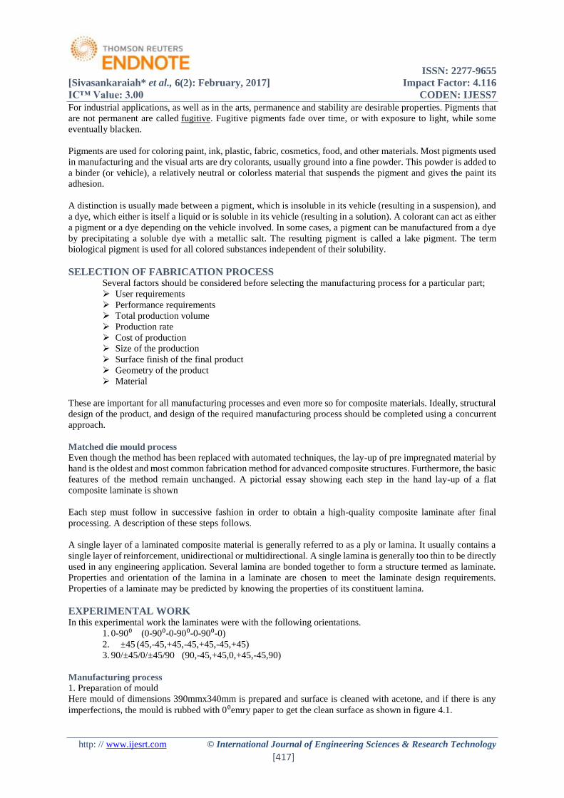
ISSN 2277-9655
[Sivasankaraiah et al 6(2) February 2017] Impact Factor 4116
ICtrade Value 300 CODEN IJESS7
http wwwijesrtcom copy International Journal of Engineering Sciences amp Research Technology
[417]
For industrial applications as well as in the arts permanence and stability are desirable properties Pigments that
are not permanent are called fugitive Fugitive pigments fade over time or with exposure to light while some
eventually blacken
Pigments are used for coloring paint ink plastic fabric cosmetics food and other materials Most pigments used
in manufacturing and the visual arts are dry colorants usually ground into a fine powder This powder is added to
a binder (or vehicle) a relatively neutral or colorless material that suspends the pigment and gives the paint its
adhesion
A distinction is usually made between a pigment which is insoluble in its vehicle (resulting in a suspension) and
a dye which either is itself a liquid or is soluble in its vehicle (resulting in a solution) A colorant can act as either
a pigment or a dye depending on the vehicle involved In some cases a pigment can be manufactured from a dye
by precipitating a soluble dye with a metallic salt The resulting pigment is called a lake pigment The term
biological pigment is used for all colored substances independent of their solubility
SELECTION OF FABRICATION PROCESS Several factors should be considered before selecting the manufacturing process for a particular part
User requirements
Performance requirements
Total production volume
Production rate
Cost of production
Size of the production
Surface finish of the final product
Geometry of the product
Material
These are important for all manufacturing processes and even more so for composite materials Ideally structural
design of the product and design of the required manufacturing process should be completed using a concurrent
approach
Matched die mould process
Even though the method has been replaced with automated techniques the lay-up of pre impregnated material by
hand is the oldest and most common fabrication method for advanced composite structures Furthermore the basic
features of the method remain unchanged A pictorial essay showing each step in the hand lay-up of a flat
composite laminate is shown
Each step must follow in successive fashion in order to obtain a high-quality composite laminate after final
processing A description of these steps follows
A single layer of a laminated composite material is generally referred to as a ply or lamina It usually contains a
single layer of reinforcement unidirectional or multidirectional A single lamina is generally too thin to be directly
used in any engineering application Several lamina are bonded together to form a structure termed as laminate
Properties and orientation of the lamina in a laminate are chosen to meet the laminate design requirements
Properties of a laminate may be predicted by knowing the properties of its constituent lamina
EXPERIMENTAL WORK In this experimental work the laminates were with the following orientations
1 0-90⁰ (0-90⁰-0-90⁰-0-90⁰-0)
2 plusmn45 (45-45+45-45+45-45+45)
3 90plusmn450plusmn4590 (90-45+450+45-4590)
Manufacturing process
1 Preparation of mould
Here mould of dimensions 390mmx340mm is prepared and surface is cleaned with acetone and if there is any
imperfections the mould is rubbed with 0⁰emry paper to get the clean surface as shown in figure 41
ISSN 2277-9655
[Sivasankaraiah et al 6(2) February 2017] Impact Factor 4116
ICtrade Value 300 CODEN IJESS7
http wwwijesrtcom copy International Journal of Engineering Sciences amp Research Technology
[418]
2 Measuring of matrix for laminate as per equal weight ratio of matrix and reinforcement That is weight of
reinforcement for one laminate equals to weight of matrix
3 The fabric is laid on the workbench which is covered with polythene sheet and then marking is taken by using
required dimensions and orientations with help of templates as shown in figure 42
4 Bonding agent(epoxy resin) is applied to create bonding between layers This is usually accomplished by rollers
or brushes with an increasing use of roller type impregnators for forcing resin in to the fabric
5Cut the fabric into laminas as per marking and place on the mold before peel outing the polythene sheet Repeat
the same process for all laminas shown in figure 43
6 After closing the mold properly allow it for curing as per cure cycle
7 Extract the laminate gently and cut the specimens according to required dimensions as per ASTM standards
Fig 41 mold
Fig 42 application of matrix over fabric
Fig 43 applying of plies over mould by sequence
IMPACT TESTING PROCEDURE Impact tests are performed to asses shock absorbing capacity of materials subjected to suddenly applied loads
In Izod test the specimen is placed as lsquocantilever beamrsquo The specimens have V-shaped notch of 45deg U-shaped
notch is also common The notch is located on tension side of specimen during impact loading Depth of notch is
generally taken as t5 to t3 where lsquotrsquo is thickness of the specimen
machine specifications
Its specifications along-with their typical values are as follows
1 Impact capacity = 164joule
2 Least count of capacity (dial) scale= 2joule
3 Weight of striking hammer = 2179 kg
ISSN 2277-9655
[Sivasankaraiah et al 6(2) February 2017] Impact Factor 4116
ICtrade Value 300 CODEN IJESS7
http wwwijesrtcom copy International Journal of Engineering Sciences amp Research Technology
[419]
4 Swing diameter of hammer = 1600mm
5 Angle of hammer before striking = 90deg
6 Striking velocity of hammer = 56msec
7 Length of the pendulum = 0796m
8 Specimen size = 64x127x32 mm3
9 Type of notch = V-notch
10 Angle of notch = 45deg
11 Depth of notch = 2 mm
Testing procedure
Check that the pendulum machine has the specified velocity of impact and that it is in the correct range of absorbed
energy
Conduct a blank test and record the measured values of the total frictional loss Ensure that this energy loss does
not exceed the appropriate value as per the standard
1 Lift the hammer to an appropriate knife edge position and notch the energy stored in the hammer For
the standard Izod test the energy stored should be 164j
2 Locate the test specimen on the mc supports shown in fig 51
3 Release the hammer The hammer will break the piece and shoot up the other side of the specimen
4 Note the residual energy indicated on the scale by the hammer
5 Impact strength of the test specimen is the difference of the initial energy stored in hammer and the
residual energy
Calculation-
bull Notch impact strength = Absorb energy Effective cross section area
Impact Strength = Impact Energy (joules)
Cross section area (mm2)
Precautions- 1 The specimen should be prepared in proper dimensions
2 Take reading more frequently
3 Make the loose pointer in contact with the fixed pointer after setting the pendulum
4 Do not stand in front of swinging hammer or releasing hammer
5 Place the specimen in proper position
figure 51 izod test rig
ISSN 2277-9655
[Sivasankaraiah et al 6(2) February 2017] Impact Factor 4116
ICtrade Value 300 CODEN IJESS7
http wwwijesrtcom copy International Journal of Engineering Sciences amp Research Technology
[420]
TEST RESULT AND DISCUSSIONS Glass fabric with lapox -L-12 and K-6 as matrix in (0900 ) (plusmn45) (090plusmn45090) orientations
Table 61 glass fabric (0-90)
figure 61
In (090) orientation of glass fabric with Lapox and K-6 exhibits good impact characteristics in un notched
conditions
whereas with the same matrix and reinforcement but with orientation of fiber is in (plusmn45) is performing better
impact result as 126 joules than (090plusmn45090) as 91 joule in izod
NOTCHEDREV
NOTCHEDUN
NOTCHED
IZOD 49 62 72
CHARPY 318 357
49 62 72
318357
05
10152025303540
JOU
LES
GLASS FABRIC+L-12+K-6
(090)
IZOD CHARPY
IZOD TEST-(090) GLASS FABRIC( L-12 RESIN + K-6 HARDNER)
SNO NOTCHED SNO REV NOTCHED SNO UN NOTCEHD
impact
energy
(joules)
impact
strength
(jmmsup2)
impact
energy
(joules)
impact
strength
(jmmsup2)
impact
energy
(joules)
impact
strength
(jmmsup2)
cross
sectional
area
(mmsup2)
1 6 014764 1 4 0098425 1 6 014764 4064
2 5 012303 2 6 0147638 2 6 014764 4064
3 4 009843 3 8 019685 3 8 019685 4064
4 4 009843 4 8 019685 4 6 014764 4064
5 4 009843 5 6 0147638 5 7 017224 4064
6 5 012303 6 6 0147638 6 8 019685 4064
7 4 009843 7 6 0147638 7 8 019685 4064
8 5 012303 8 6 0147638 8 8 019685 4064
9 4 009843 9 6 0147638 9 7 017224 4064
10 8 019685 10 6 0147638 10 8 019685 4064
Average 49 01206 62 015256 72 01772
ISSN 2277-9655
[Sivasankaraiah et al 6(2) February 2017] Impact Factor 4116
ICtrade Value 300 CODEN IJESS7
http wwwijesrtcom copy International Journal of Engineering Sciences amp Research Technology
[421]
figure 62
4All fibers are oriented to 450 to pendulum in plusmn45 orientation this helps to absorb more impact energy and the
same reason this orientation absorbs less in charpy test compared to (090)
62 Carbon fiber with lapox -L-12 and Aradur 5200 as matrix in (090plusmn45090) orientation
Table 62 carbon fibre (090plusmn45090)
62 Carbon fiber with lapox -L-12 and Aradur 5200 as matrix in (plusmn45) (090plusmn45090) orientations
1 Carbon fiber with Aradur 5200 hardener giving good izod impact results in (plusmn45) orientation than the
(090plusmn45090) and (090)
2 In (090) fiber orientation both glass and carbon fiber performing good charpy impact results
3 The izod impact characteristics carbon with aradur 5200 hardener is exhibiting approximately same
results when fiber oriented in ( 090plusmn45090) and ( plusmn45) This is because fibers oriented in plusmn45 will
give great shear strength
4 Where as in the case of charpy the number of fibers which are oriented in (090) will gives better results
than (090plusmn45090) (plusmn45)
NOTCHEDREV
NOTCHEDUN
NOTCHED
IZOD 74 104 126
CHARPY 232 29
74104
126
232
29
0
5
10
15
20
25
30
35
JOU
LES
GLASS FABRIC+L-12+K-6(plusmn45)
IZOD CHARPY
IZOD TEST-COMBINATIONAL CARBON FIBER( L-12 + ARADUR 5200)
SNO NOTCHED SNO REV NOTCHED SNO UN NOTCEHD
impact
energy
(joules)
impact
strength
(jmmsup2)
impact
energy
(joules)
impact
strength
(jmmsup2)
impact
energy
(joules)
impact
strength
(jmmsup2)
cross
sectional
area
(mmsup2)
1 10 024606 1 14 0344488 1 13 031988 4064
2 14 034449 2 12 0295276 2 12 029528 4064
3 10 024606 3 12 0295276 3 15 036909 4064
4 12 029528 4 12 0295276 4 18 044291 4064
5 12 029528 5 13 0319882 5 15 036909 4064
6 11 027067 6 12 0295276 6 15 036909 4064
7 12 029528 7 10 0246063 7 15 036909 4064
8 13 031988 8 10 0246063 8 14 034449 4064
9 13 031988 9 12 0295276 9 15 036909 4064
10 12 029528 10 12 0295276 10 8 019685 4064
Average 119 024606 119 029281 14 03445
ISSN 2277-9655
[Sivasankaraiah et al 6(2) February 2017] Impact Factor 4116
ICtrade Value 300 CODEN IJESS7
http wwwijesrtcom copy International Journal of Engineering Sciences amp Research Technology
[422]
Table 63 carbon fiber (plusmn45)
figure 63
Glass fiber with lapox -L-12 and Aradur 5200 as matrix in (plusmn45) (090plusmn45090) orientations
Glass fiber with Lapox L-12 and aradur 5200 combination performing good impact results in izod (1333joules)
than glass fabric with the same matrix composition(126 joules) in plusmn45 fiber orientation and in (090plusmn45090)
fiber orientation also glass fiber shows improvement over fabric shown in figure 64
figure 64
NOTCHEDREV
NOTCHEDUN
NOTCHED
IZOD 119 119 14
CHARPY 229 253
119 11914
229253
0
5
10
15
20
25
30
JOU
LES
CARBON FIBER +L12+ARADUR
5200+(090plusmn45090)
IZOD CHARPY
NOTCHEDREV
NOTCHEDUN
NOTCHED
IZOD 1133 1166 1333
CHARPY 23 283
1133 1166 1333
23283
05
1015202530
JOU
LES
GLASS FIBER +L-12+aradur 5200+
(plusmn45)
IZOD CHARPY
ISSN 2277-9655
[Sivasankaraiah et al 6(2) February 2017] Impact Factor 4116
ICtrade Value 300 CODEN IJESS7
http wwwijesrtcom copy International Journal of Engineering Sciences amp Research Technology
[423]
CONCLUSIONS 1 In the present investigation on impact characteristics of polymer matrix composites depends upon
reinforcement orientation of the reinforcement and matrix composition
2 The characterization was carried among three reinforcements glass fabric glass fiber carbon fiber and
three orientations that is (090)(090plusmn45090) (plusmn45) with different matrix systems (lapox L-12+ K-
6) (lapox L-12+ aradur 5200)
3 Carbon fiber with (plusmn45) orientation in composition of Lapox L-12+ Aradur 5200 giving best in both izod
and chary impact characteristics
4 Glass fiber in (plusmn45) orientation in composition of Lapox L-12+ Aradur 5200 giving approximate results
with carbon fiber in both izod and chary impact characteristics
5 Glass fabric with (lapox L-12+ K-6) in (090) orientation giving lowest izod impact result
6 In (090plusmn45090) orientation the reinforcement giving intermediate results of reinforcement in (090)
(plusmn45) in respective matrix composition
REFERENCES [1] httpwikipediaorgwikiinteoduction to composite materials
[2] httpenwikipediaorgwikiclassification of composite materials
[3] httpenwikipediaorgwikitypes of fibre reinforcements
[4] httpenwikipediaorgwikitypes of matrix materials
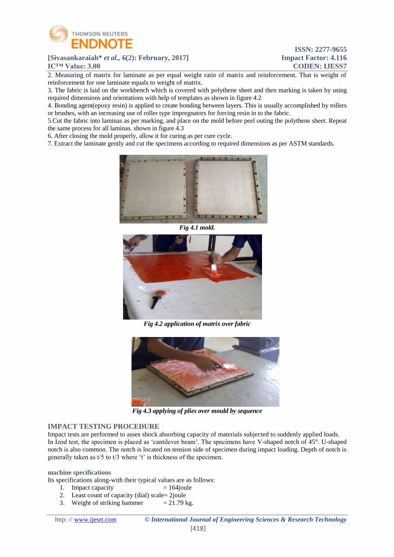
ISSN 2277-9655
[Sivasankaraiah et al 6(2) February 2017] Impact Factor 4116
ICtrade Value 300 CODEN IJESS7
http wwwijesrtcom copy International Journal of Engineering Sciences amp Research Technology
[418]
2 Measuring of matrix for laminate as per equal weight ratio of matrix and reinforcement That is weight of
reinforcement for one laminate equals to weight of matrix
3 The fabric is laid on the workbench which is covered with polythene sheet and then marking is taken by using
required dimensions and orientations with help of templates as shown in figure 42
4 Bonding agent(epoxy resin) is applied to create bonding between layers This is usually accomplished by rollers
or brushes with an increasing use of roller type impregnators for forcing resin in to the fabric
5Cut the fabric into laminas as per marking and place on the mold before peel outing the polythene sheet Repeat
the same process for all laminas shown in figure 43
6 After closing the mold properly allow it for curing as per cure cycle
7 Extract the laminate gently and cut the specimens according to required dimensions as per ASTM standards
Fig 41 mold
Fig 42 application of matrix over fabric
Fig 43 applying of plies over mould by sequence
IMPACT TESTING PROCEDURE Impact tests are performed to asses shock absorbing capacity of materials subjected to suddenly applied loads
In Izod test the specimen is placed as lsquocantilever beamrsquo The specimens have V-shaped notch of 45deg U-shaped
notch is also common The notch is located on tension side of specimen during impact loading Depth of notch is
generally taken as t5 to t3 where lsquotrsquo is thickness of the specimen
machine specifications
Its specifications along-with their typical values are as follows
1 Impact capacity = 164joule
2 Least count of capacity (dial) scale= 2joule
3 Weight of striking hammer = 2179 kg
ISSN 2277-9655
[Sivasankaraiah et al 6(2) February 2017] Impact Factor 4116
ICtrade Value 300 CODEN IJESS7
http wwwijesrtcom copy International Journal of Engineering Sciences amp Research Technology
[419]
4 Swing diameter of hammer = 1600mm
5 Angle of hammer before striking = 90deg
6 Striking velocity of hammer = 56msec
7 Length of the pendulum = 0796m
8 Specimen size = 64x127x32 mm3
9 Type of notch = V-notch
10 Angle of notch = 45deg
11 Depth of notch = 2 mm
Testing procedure
Check that the pendulum machine has the specified velocity of impact and that it is in the correct range of absorbed
energy
Conduct a blank test and record the measured values of the total frictional loss Ensure that this energy loss does
not exceed the appropriate value as per the standard
1 Lift the hammer to an appropriate knife edge position and notch the energy stored in the hammer For
the standard Izod test the energy stored should be 164j
2 Locate the test specimen on the mc supports shown in fig 51
3 Release the hammer The hammer will break the piece and shoot up the other side of the specimen
4 Note the residual energy indicated on the scale by the hammer
5 Impact strength of the test specimen is the difference of the initial energy stored in hammer and the
residual energy
Calculation-
bull Notch impact strength = Absorb energy Effective cross section area
Impact Strength = Impact Energy (joules)
Cross section area (mm2)
Precautions- 1 The specimen should be prepared in proper dimensions
2 Take reading more frequently
3 Make the loose pointer in contact with the fixed pointer after setting the pendulum
4 Do not stand in front of swinging hammer or releasing hammer
5 Place the specimen in proper position
figure 51 izod test rig
ISSN 2277-9655
[Sivasankaraiah et al 6(2) February 2017] Impact Factor 4116
ICtrade Value 300 CODEN IJESS7
http wwwijesrtcom copy International Journal of Engineering Sciences amp Research Technology
[420]
TEST RESULT AND DISCUSSIONS Glass fabric with lapox -L-12 and K-6 as matrix in (0900 ) (plusmn45) (090plusmn45090) orientations
Table 61 glass fabric (0-90)
figure 61
In (090) orientation of glass fabric with Lapox and K-6 exhibits good impact characteristics in un notched
conditions
whereas with the same matrix and reinforcement but with orientation of fiber is in (plusmn45) is performing better
impact result as 126 joules than (090plusmn45090) as 91 joule in izod
NOTCHEDREV
NOTCHEDUN
NOTCHED
IZOD 49 62 72
CHARPY 318 357
49 62 72
318357
05
10152025303540
JOU
LES
GLASS FABRIC+L-12+K-6
(090)
IZOD CHARPY
IZOD TEST-(090) GLASS FABRIC( L-12 RESIN + K-6 HARDNER)
SNO NOTCHED SNO REV NOTCHED SNO UN NOTCEHD
impact
energy
(joules)
impact
strength
(jmmsup2)
impact
energy
(joules)
impact
strength
(jmmsup2)
impact
energy
(joules)
impact
strength
(jmmsup2)
cross
sectional
area
(mmsup2)
1 6 014764 1 4 0098425 1 6 014764 4064
2 5 012303 2 6 0147638 2 6 014764 4064
3 4 009843 3 8 019685 3 8 019685 4064
4 4 009843 4 8 019685 4 6 014764 4064
5 4 009843 5 6 0147638 5 7 017224 4064
6 5 012303 6 6 0147638 6 8 019685 4064
7 4 009843 7 6 0147638 7 8 019685 4064
8 5 012303 8 6 0147638 8 8 019685 4064
9 4 009843 9 6 0147638 9 7 017224 4064
10 8 019685 10 6 0147638 10 8 019685 4064
Average 49 01206 62 015256 72 01772
ISSN 2277-9655
[Sivasankaraiah et al 6(2) February 2017] Impact Factor 4116
ICtrade Value 300 CODEN IJESS7
http wwwijesrtcom copy International Journal of Engineering Sciences amp Research Technology
[421]
figure 62
4All fibers are oriented to 450 to pendulum in plusmn45 orientation this helps to absorb more impact energy and the
same reason this orientation absorbs less in charpy test compared to (090)
62 Carbon fiber with lapox -L-12 and Aradur 5200 as matrix in (090plusmn45090) orientation
Table 62 carbon fibre (090plusmn45090)
62 Carbon fiber with lapox -L-12 and Aradur 5200 as matrix in (plusmn45) (090plusmn45090) orientations
1 Carbon fiber with Aradur 5200 hardener giving good izod impact results in (plusmn45) orientation than the
(090plusmn45090) and (090)
2 In (090) fiber orientation both glass and carbon fiber performing good charpy impact results
3 The izod impact characteristics carbon with aradur 5200 hardener is exhibiting approximately same
results when fiber oriented in ( 090plusmn45090) and ( plusmn45) This is because fibers oriented in plusmn45 will
give great shear strength
4 Where as in the case of charpy the number of fibers which are oriented in (090) will gives better results
than (090plusmn45090) (plusmn45)
NOTCHEDREV
NOTCHEDUN
NOTCHED
IZOD 74 104 126
CHARPY 232 29
74104
126
232
29
0
5
10
15
20
25
30
35
JOU
LES
GLASS FABRIC+L-12+K-6(plusmn45)
IZOD CHARPY
IZOD TEST-COMBINATIONAL CARBON FIBER( L-12 + ARADUR 5200)
SNO NOTCHED SNO REV NOTCHED SNO UN NOTCEHD
impact
energy
(joules)
impact
strength
(jmmsup2)
impact
energy
(joules)
impact
strength
(jmmsup2)
impact
energy
(joules)
impact
strength
(jmmsup2)
cross
sectional
area
(mmsup2)
1 10 024606 1 14 0344488 1 13 031988 4064
2 14 034449 2 12 0295276 2 12 029528 4064
3 10 024606 3 12 0295276 3 15 036909 4064
4 12 029528 4 12 0295276 4 18 044291 4064
5 12 029528 5 13 0319882 5 15 036909 4064
6 11 027067 6 12 0295276 6 15 036909 4064
7 12 029528 7 10 0246063 7 15 036909 4064
8 13 031988 8 10 0246063 8 14 034449 4064
9 13 031988 9 12 0295276 9 15 036909 4064
10 12 029528 10 12 0295276 10 8 019685 4064
Average 119 024606 119 029281 14 03445
ISSN 2277-9655
[Sivasankaraiah et al 6(2) February 2017] Impact Factor 4116
ICtrade Value 300 CODEN IJESS7
http wwwijesrtcom copy International Journal of Engineering Sciences amp Research Technology
[422]
Table 63 carbon fiber (plusmn45)
figure 63
Glass fiber with lapox -L-12 and Aradur 5200 as matrix in (plusmn45) (090plusmn45090) orientations
Glass fiber with Lapox L-12 and aradur 5200 combination performing good impact results in izod (1333joules)
than glass fabric with the same matrix composition(126 joules) in plusmn45 fiber orientation and in (090plusmn45090)
fiber orientation also glass fiber shows improvement over fabric shown in figure 64
figure 64
NOTCHEDREV
NOTCHEDUN
NOTCHED
IZOD 119 119 14
CHARPY 229 253
119 11914
229253
0
5
10
15
20
25
30
JOU
LES
CARBON FIBER +L12+ARADUR
5200+(090plusmn45090)
IZOD CHARPY
NOTCHEDREV
NOTCHEDUN
NOTCHED
IZOD 1133 1166 1333
CHARPY 23 283
1133 1166 1333
23283
05
1015202530
JOU
LES
GLASS FIBER +L-12+aradur 5200+
(plusmn45)
IZOD CHARPY
ISSN 2277-9655
[Sivasankaraiah et al 6(2) February 2017] Impact Factor 4116
ICtrade Value 300 CODEN IJESS7
http wwwijesrtcom copy International Journal of Engineering Sciences amp Research Technology
[423]
CONCLUSIONS 1 In the present investigation on impact characteristics of polymer matrix composites depends upon
reinforcement orientation of the reinforcement and matrix composition
2 The characterization was carried among three reinforcements glass fabric glass fiber carbon fiber and
three orientations that is (090)(090plusmn45090) (plusmn45) with different matrix systems (lapox L-12+ K-
6) (lapox L-12+ aradur 5200)
3 Carbon fiber with (plusmn45) orientation in composition of Lapox L-12+ Aradur 5200 giving best in both izod
and chary impact characteristics
4 Glass fiber in (plusmn45) orientation in composition of Lapox L-12+ Aradur 5200 giving approximate results
with carbon fiber in both izod and chary impact characteristics
5 Glass fabric with (lapox L-12+ K-6) in (090) orientation giving lowest izod impact result
6 In (090plusmn45090) orientation the reinforcement giving intermediate results of reinforcement in (090)
(plusmn45) in respective matrix composition
REFERENCES [1] httpwikipediaorgwikiinteoduction to composite materials
[2] httpenwikipediaorgwikiclassification of composite materials
[3] httpenwikipediaorgwikitypes of fibre reinforcements
[4] httpenwikipediaorgwikitypes of matrix materials
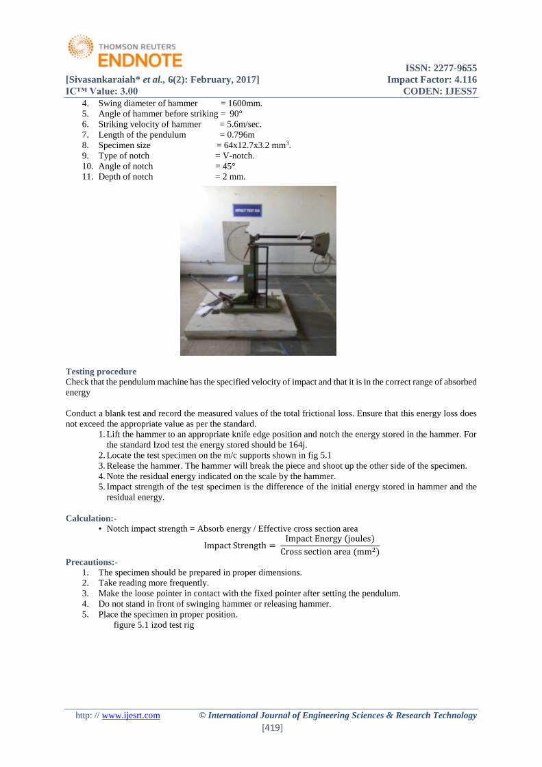
ISSN 2277-9655
[Sivasankaraiah et al 6(2) February 2017] Impact Factor 4116
ICtrade Value 300 CODEN IJESS7
http wwwijesrtcom copy International Journal of Engineering Sciences amp Research Technology
[419]
4 Swing diameter of hammer = 1600mm
5 Angle of hammer before striking = 90deg
6 Striking velocity of hammer = 56msec
7 Length of the pendulum = 0796m
8 Specimen size = 64x127x32 mm3
9 Type of notch = V-notch
10 Angle of notch = 45deg
11 Depth of notch = 2 mm
Testing procedure
Check that the pendulum machine has the specified velocity of impact and that it is in the correct range of absorbed
energy
Conduct a blank test and record the measured values of the total frictional loss Ensure that this energy loss does
not exceed the appropriate value as per the standard
1 Lift the hammer to an appropriate knife edge position and notch the energy stored in the hammer For
the standard Izod test the energy stored should be 164j
2 Locate the test specimen on the mc supports shown in fig 51
3 Release the hammer The hammer will break the piece and shoot up the other side of the specimen
4 Note the residual energy indicated on the scale by the hammer
5 Impact strength of the test specimen is the difference of the initial energy stored in hammer and the
residual energy
Calculation-
bull Notch impact strength = Absorb energy Effective cross section area
Impact Strength = Impact Energy (joules)
Cross section area (mm2)
Precautions- 1 The specimen should be prepared in proper dimensions
2 Take reading more frequently
3 Make the loose pointer in contact with the fixed pointer after setting the pendulum
4 Do not stand in front of swinging hammer or releasing hammer
5 Place the specimen in proper position
figure 51 izod test rig
ISSN 2277-9655
[Sivasankaraiah et al 6(2) February 2017] Impact Factor 4116
ICtrade Value 300 CODEN IJESS7
http wwwijesrtcom copy International Journal of Engineering Sciences amp Research Technology
[420]
TEST RESULT AND DISCUSSIONS Glass fabric with lapox -L-12 and K-6 as matrix in (0900 ) (plusmn45) (090plusmn45090) orientations
Table 61 glass fabric (0-90)
figure 61
In (090) orientation of glass fabric with Lapox and K-6 exhibits good impact characteristics in un notched
conditions
whereas with the same matrix and reinforcement but with orientation of fiber is in (plusmn45) is performing better
impact result as 126 joules than (090plusmn45090) as 91 joule in izod
NOTCHEDREV
NOTCHEDUN
NOTCHED
IZOD 49 62 72
CHARPY 318 357
49 62 72
318357
05
10152025303540
JOU
LES
GLASS FABRIC+L-12+K-6
(090)
IZOD CHARPY
IZOD TEST-(090) GLASS FABRIC( L-12 RESIN + K-6 HARDNER)
SNO NOTCHED SNO REV NOTCHED SNO UN NOTCEHD
impact
energy
(joules)
impact
strength
(jmmsup2)
impact
energy
(joules)
impact
strength
(jmmsup2)
impact
energy
(joules)
impact
strength
(jmmsup2)
cross
sectional
area
(mmsup2)
1 6 014764 1 4 0098425 1 6 014764 4064
2 5 012303 2 6 0147638 2 6 014764 4064
3 4 009843 3 8 019685 3 8 019685 4064
4 4 009843 4 8 019685 4 6 014764 4064
5 4 009843 5 6 0147638 5 7 017224 4064
6 5 012303 6 6 0147638 6 8 019685 4064
7 4 009843 7 6 0147638 7 8 019685 4064
8 5 012303 8 6 0147638 8 8 019685 4064
9 4 009843 9 6 0147638 9 7 017224 4064
10 8 019685 10 6 0147638 10 8 019685 4064
Average 49 01206 62 015256 72 01772
ISSN 2277-9655
[Sivasankaraiah et al 6(2) February 2017] Impact Factor 4116
ICtrade Value 300 CODEN IJESS7
http wwwijesrtcom copy International Journal of Engineering Sciences amp Research Technology
[421]
figure 62
4All fibers are oriented to 450 to pendulum in plusmn45 orientation this helps to absorb more impact energy and the
same reason this orientation absorbs less in charpy test compared to (090)
62 Carbon fiber with lapox -L-12 and Aradur 5200 as matrix in (090plusmn45090) orientation
Table 62 carbon fibre (090plusmn45090)
62 Carbon fiber with lapox -L-12 and Aradur 5200 as matrix in (plusmn45) (090plusmn45090) orientations
1 Carbon fiber with Aradur 5200 hardener giving good izod impact results in (plusmn45) orientation than the
(090plusmn45090) and (090)
2 In (090) fiber orientation both glass and carbon fiber performing good charpy impact results
3 The izod impact characteristics carbon with aradur 5200 hardener is exhibiting approximately same
results when fiber oriented in ( 090plusmn45090) and ( plusmn45) This is because fibers oriented in plusmn45 will
give great shear strength
4 Where as in the case of charpy the number of fibers which are oriented in (090) will gives better results
than (090plusmn45090) (plusmn45)
NOTCHEDREV
NOTCHEDUN
NOTCHED
IZOD 74 104 126
CHARPY 232 29
74104
126
232
29
0
5
10
15
20
25
30
35
JOU
LES
GLASS FABRIC+L-12+K-6(plusmn45)
IZOD CHARPY
IZOD TEST-COMBINATIONAL CARBON FIBER( L-12 + ARADUR 5200)
SNO NOTCHED SNO REV NOTCHED SNO UN NOTCEHD
impact
energy
(joules)
impact
strength
(jmmsup2)
impact
energy
(joules)
impact
strength
(jmmsup2)
impact
energy
(joules)
impact
strength
(jmmsup2)
cross
sectional
area
(mmsup2)
1 10 024606 1 14 0344488 1 13 031988 4064
2 14 034449 2 12 0295276 2 12 029528 4064
3 10 024606 3 12 0295276 3 15 036909 4064
4 12 029528 4 12 0295276 4 18 044291 4064
5 12 029528 5 13 0319882 5 15 036909 4064
6 11 027067 6 12 0295276 6 15 036909 4064
7 12 029528 7 10 0246063 7 15 036909 4064
8 13 031988 8 10 0246063 8 14 034449 4064
9 13 031988 9 12 0295276 9 15 036909 4064
10 12 029528 10 12 0295276 10 8 019685 4064
Average 119 024606 119 029281 14 03445
ISSN 2277-9655
[Sivasankaraiah et al 6(2) February 2017] Impact Factor 4116
ICtrade Value 300 CODEN IJESS7
http wwwijesrtcom copy International Journal of Engineering Sciences amp Research Technology
[422]
Table 63 carbon fiber (plusmn45)
figure 63
Glass fiber with lapox -L-12 and Aradur 5200 as matrix in (plusmn45) (090plusmn45090) orientations
Glass fiber with Lapox L-12 and aradur 5200 combination performing good impact results in izod (1333joules)
than glass fabric with the same matrix composition(126 joules) in plusmn45 fiber orientation and in (090plusmn45090)
fiber orientation also glass fiber shows improvement over fabric shown in figure 64
figure 64
NOTCHEDREV
NOTCHEDUN
NOTCHED
IZOD 119 119 14
CHARPY 229 253
119 11914
229253
0
5
10
15
20
25
30
JOU
LES
CARBON FIBER +L12+ARADUR
5200+(090plusmn45090)
IZOD CHARPY
NOTCHEDREV
NOTCHEDUN
NOTCHED
IZOD 1133 1166 1333
CHARPY 23 283
1133 1166 1333
23283
05
1015202530
JOU
LES
GLASS FIBER +L-12+aradur 5200+
(plusmn45)
IZOD CHARPY
ISSN 2277-9655
[Sivasankaraiah et al 6(2) February 2017] Impact Factor 4116
ICtrade Value 300 CODEN IJESS7
http wwwijesrtcom copy International Journal of Engineering Sciences amp Research Technology
[423]
CONCLUSIONS 1 In the present investigation on impact characteristics of polymer matrix composites depends upon
reinforcement orientation of the reinforcement and matrix composition
2 The characterization was carried among three reinforcements glass fabric glass fiber carbon fiber and
three orientations that is (090)(090plusmn45090) (plusmn45) with different matrix systems (lapox L-12+ K-
6) (lapox L-12+ aradur 5200)
3 Carbon fiber with (plusmn45) orientation in composition of Lapox L-12+ Aradur 5200 giving best in both izod
and chary impact characteristics
4 Glass fiber in (plusmn45) orientation in composition of Lapox L-12+ Aradur 5200 giving approximate results
with carbon fiber in both izod and chary impact characteristics
5 Glass fabric with (lapox L-12+ K-6) in (090) orientation giving lowest izod impact result
6 In (090plusmn45090) orientation the reinforcement giving intermediate results of reinforcement in (090)
(plusmn45) in respective matrix composition
REFERENCES [1] httpwikipediaorgwikiinteoduction to composite materials
[2] httpenwikipediaorgwikiclassification of composite materials
[3] httpenwikipediaorgwikitypes of fibre reinforcements
[4] httpenwikipediaorgwikitypes of matrix materials
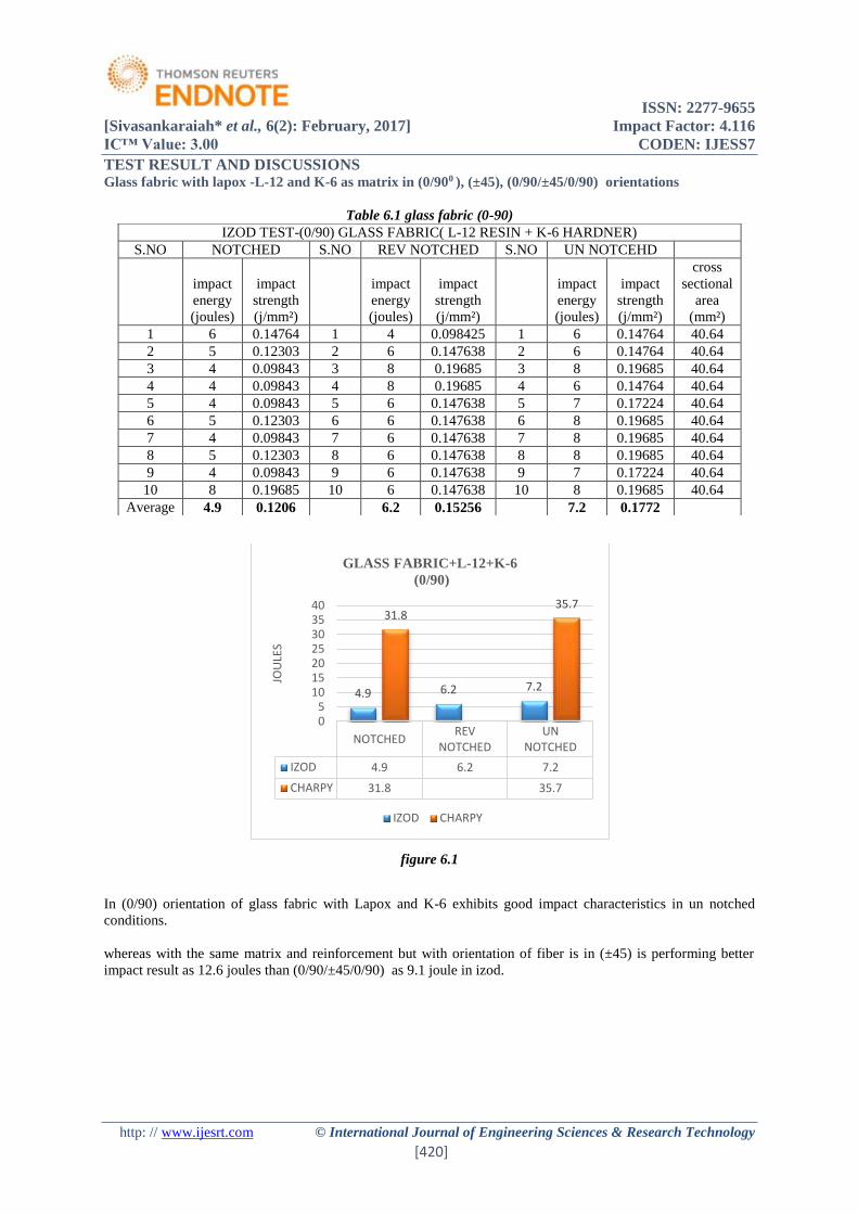
ISSN 2277-9655
[Sivasankaraiah et al 6(2) February 2017] Impact Factor 4116
ICtrade Value 300 CODEN IJESS7
http wwwijesrtcom copy International Journal of Engineering Sciences amp Research Technology
[420]
TEST RESULT AND DISCUSSIONS Glass fabric with lapox -L-12 and K-6 as matrix in (0900 ) (plusmn45) (090plusmn45090) orientations
Table 61 glass fabric (0-90)
figure 61
In (090) orientation of glass fabric with Lapox and K-6 exhibits good impact characteristics in un notched
conditions
whereas with the same matrix and reinforcement but with orientation of fiber is in (plusmn45) is performing better
impact result as 126 joules than (090plusmn45090) as 91 joule in izod
NOTCHEDREV
NOTCHEDUN
NOTCHED
IZOD 49 62 72
CHARPY 318 357
49 62 72
318357
05
10152025303540
JOU
LES
GLASS FABRIC+L-12+K-6
(090)
IZOD CHARPY
IZOD TEST-(090) GLASS FABRIC( L-12 RESIN + K-6 HARDNER)
SNO NOTCHED SNO REV NOTCHED SNO UN NOTCEHD
impact
energy
(joules)
impact
strength
(jmmsup2)
impact
energy
(joules)
impact
strength
(jmmsup2)
impact
energy
(joules)
impact
strength
(jmmsup2)
cross
sectional
area
(mmsup2)
1 6 014764 1 4 0098425 1 6 014764 4064
2 5 012303 2 6 0147638 2 6 014764 4064
3 4 009843 3 8 019685 3 8 019685 4064
4 4 009843 4 8 019685 4 6 014764 4064
5 4 009843 5 6 0147638 5 7 017224 4064
6 5 012303 6 6 0147638 6 8 019685 4064
7 4 009843 7 6 0147638 7 8 019685 4064
8 5 012303 8 6 0147638 8 8 019685 4064
9 4 009843 9 6 0147638 9 7 017224 4064
10 8 019685 10 6 0147638 10 8 019685 4064
Average 49 01206 62 015256 72 01772
ISSN 2277-9655
[Sivasankaraiah et al 6(2) February 2017] Impact Factor 4116
ICtrade Value 300 CODEN IJESS7
http wwwijesrtcom copy International Journal of Engineering Sciences amp Research Technology
[421]
figure 62
4All fibers are oriented to 450 to pendulum in plusmn45 orientation this helps to absorb more impact energy and the
same reason this orientation absorbs less in charpy test compared to (090)
62 Carbon fiber with lapox -L-12 and Aradur 5200 as matrix in (090plusmn45090) orientation
Table 62 carbon fibre (090plusmn45090)
62 Carbon fiber with lapox -L-12 and Aradur 5200 as matrix in (plusmn45) (090plusmn45090) orientations
1 Carbon fiber with Aradur 5200 hardener giving good izod impact results in (plusmn45) orientation than the
(090plusmn45090) and (090)
2 In (090) fiber orientation both glass and carbon fiber performing good charpy impact results
3 The izod impact characteristics carbon with aradur 5200 hardener is exhibiting approximately same
results when fiber oriented in ( 090plusmn45090) and ( plusmn45) This is because fibers oriented in plusmn45 will
give great shear strength
4 Where as in the case of charpy the number of fibers which are oriented in (090) will gives better results
than (090plusmn45090) (plusmn45)
NOTCHEDREV
NOTCHEDUN
NOTCHED
IZOD 74 104 126
CHARPY 232 29
74104
126
232
29
0
5
10
15
20
25
30
35
JOU
LES
GLASS FABRIC+L-12+K-6(plusmn45)
IZOD CHARPY
IZOD TEST-COMBINATIONAL CARBON FIBER( L-12 + ARADUR 5200)
SNO NOTCHED SNO REV NOTCHED SNO UN NOTCEHD
impact
energy
(joules)
impact
strength
(jmmsup2)
impact
energy
(joules)
impact
strength
(jmmsup2)
impact
energy
(joules)
impact
strength
(jmmsup2)
cross
sectional
area
(mmsup2)
1 10 024606 1 14 0344488 1 13 031988 4064
2 14 034449 2 12 0295276 2 12 029528 4064
3 10 024606 3 12 0295276 3 15 036909 4064
4 12 029528 4 12 0295276 4 18 044291 4064
5 12 029528 5 13 0319882 5 15 036909 4064
6 11 027067 6 12 0295276 6 15 036909 4064
7 12 029528 7 10 0246063 7 15 036909 4064
8 13 031988 8 10 0246063 8 14 034449 4064
9 13 031988 9 12 0295276 9 15 036909 4064
10 12 029528 10 12 0295276 10 8 019685 4064
Average 119 024606 119 029281 14 03445
ISSN 2277-9655
[Sivasankaraiah et al 6(2) February 2017] Impact Factor 4116
ICtrade Value 300 CODEN IJESS7
http wwwijesrtcom copy International Journal of Engineering Sciences amp Research Technology
[422]
Table 63 carbon fiber (plusmn45)
figure 63
Glass fiber with lapox -L-12 and Aradur 5200 as matrix in (plusmn45) (090plusmn45090) orientations
Glass fiber with Lapox L-12 and aradur 5200 combination performing good impact results in izod (1333joules)
than glass fabric with the same matrix composition(126 joules) in plusmn45 fiber orientation and in (090plusmn45090)
fiber orientation also glass fiber shows improvement over fabric shown in figure 64
figure 64
NOTCHEDREV
NOTCHEDUN
NOTCHED
IZOD 119 119 14
CHARPY 229 253
119 11914
229253
0
5
10
15
20
25
30
JOU
LES
CARBON FIBER +L12+ARADUR
5200+(090plusmn45090)
IZOD CHARPY
NOTCHEDREV
NOTCHEDUN
NOTCHED
IZOD 1133 1166 1333
CHARPY 23 283
1133 1166 1333
23283
05
1015202530
JOU
LES
GLASS FIBER +L-12+aradur 5200+
(plusmn45)
IZOD CHARPY
ISSN 2277-9655
[Sivasankaraiah et al 6(2) February 2017] Impact Factor 4116
ICtrade Value 300 CODEN IJESS7
http wwwijesrtcom copy International Journal of Engineering Sciences amp Research Technology
[423]
CONCLUSIONS 1 In the present investigation on impact characteristics of polymer matrix composites depends upon
reinforcement orientation of the reinforcement and matrix composition
2 The characterization was carried among three reinforcements glass fabric glass fiber carbon fiber and
three orientations that is (090)(090plusmn45090) (plusmn45) with different matrix systems (lapox L-12+ K-
6) (lapox L-12+ aradur 5200)
3 Carbon fiber with (plusmn45) orientation in composition of Lapox L-12+ Aradur 5200 giving best in both izod
and chary impact characteristics
4 Glass fiber in (plusmn45) orientation in composition of Lapox L-12+ Aradur 5200 giving approximate results
with carbon fiber in both izod and chary impact characteristics
5 Glass fabric with (lapox L-12+ K-6) in (090) orientation giving lowest izod impact result
6 In (090plusmn45090) orientation the reinforcement giving intermediate results of reinforcement in (090)
(plusmn45) in respective matrix composition
REFERENCES [1] httpwikipediaorgwikiinteoduction to composite materials
[2] httpenwikipediaorgwikiclassification of composite materials
[3] httpenwikipediaorgwikitypes of fibre reinforcements
[4] httpenwikipediaorgwikitypes of matrix materials
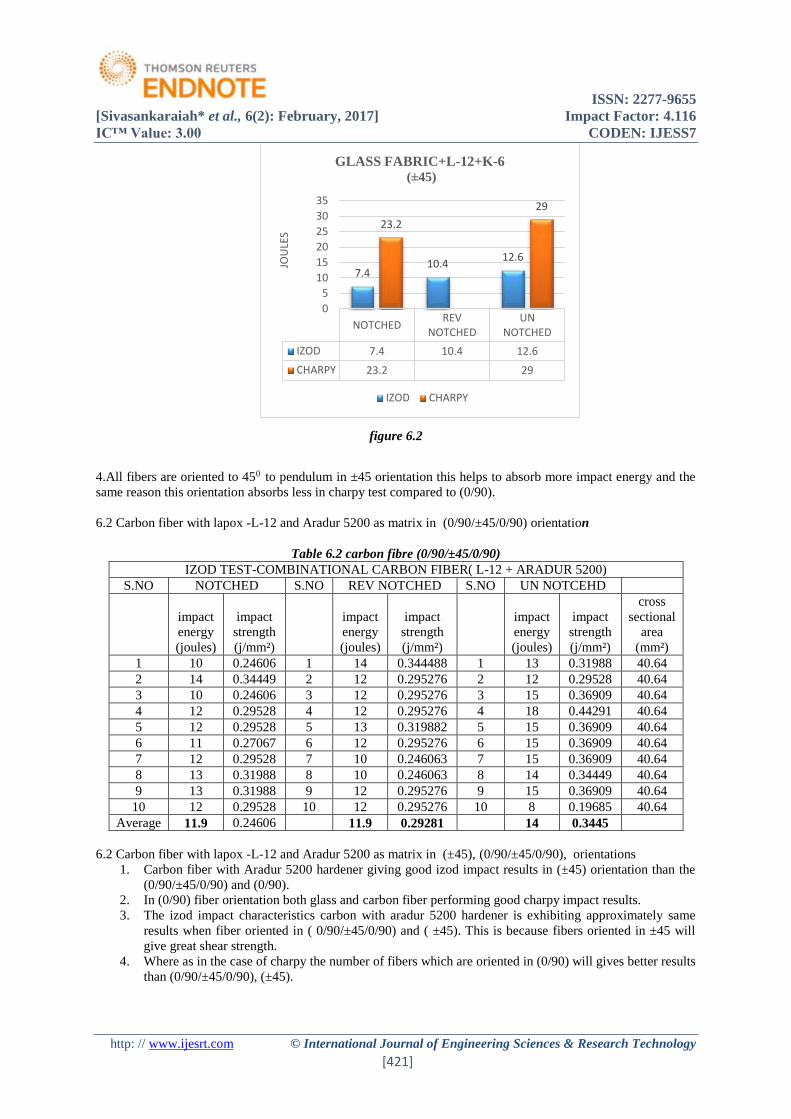
ISSN 2277-9655
[Sivasankaraiah et al 6(2) February 2017] Impact Factor 4116
ICtrade Value 300 CODEN IJESS7
http wwwijesrtcom copy International Journal of Engineering Sciences amp Research Technology
[421]
figure 62
4All fibers are oriented to 450 to pendulum in plusmn45 orientation this helps to absorb more impact energy and the
same reason this orientation absorbs less in charpy test compared to (090)
62 Carbon fiber with lapox -L-12 and Aradur 5200 as matrix in (090plusmn45090) orientation
Table 62 carbon fibre (090plusmn45090)
62 Carbon fiber with lapox -L-12 and Aradur 5200 as matrix in (plusmn45) (090plusmn45090) orientations
1 Carbon fiber with Aradur 5200 hardener giving good izod impact results in (plusmn45) orientation than the
(090plusmn45090) and (090)
2 In (090) fiber orientation both glass and carbon fiber performing good charpy impact results
3 The izod impact characteristics carbon with aradur 5200 hardener is exhibiting approximately same
results when fiber oriented in ( 090plusmn45090) and ( plusmn45) This is because fibers oriented in plusmn45 will
give great shear strength
4 Where as in the case of charpy the number of fibers which are oriented in (090) will gives better results
than (090plusmn45090) (plusmn45)
NOTCHEDREV
NOTCHEDUN
NOTCHED
IZOD 74 104 126
CHARPY 232 29
74104
126
232
29
0
5
10
15
20
25
30
35
JOU
LES
GLASS FABRIC+L-12+K-6(plusmn45)
IZOD CHARPY
IZOD TEST-COMBINATIONAL CARBON FIBER( L-12 + ARADUR 5200)
SNO NOTCHED SNO REV NOTCHED SNO UN NOTCEHD
impact
energy
(joules)
impact
strength
(jmmsup2)
impact
energy
(joules)
impact
strength
(jmmsup2)
impact
energy
(joules)
impact
strength
(jmmsup2)
cross
sectional
area
(mmsup2)
1 10 024606 1 14 0344488 1 13 031988 4064
2 14 034449 2 12 0295276 2 12 029528 4064
3 10 024606 3 12 0295276 3 15 036909 4064
4 12 029528 4 12 0295276 4 18 044291 4064
5 12 029528 5 13 0319882 5 15 036909 4064
6 11 027067 6 12 0295276 6 15 036909 4064
7 12 029528 7 10 0246063 7 15 036909 4064
8 13 031988 8 10 0246063 8 14 034449 4064
9 13 031988 9 12 0295276 9 15 036909 4064
10 12 029528 10 12 0295276 10 8 019685 4064
Average 119 024606 119 029281 14 03445
ISSN 2277-9655
[Sivasankaraiah et al 6(2) February 2017] Impact Factor 4116
ICtrade Value 300 CODEN IJESS7
http wwwijesrtcom copy International Journal of Engineering Sciences amp Research Technology
[422]
Table 63 carbon fiber (plusmn45)
figure 63
Glass fiber with lapox -L-12 and Aradur 5200 as matrix in (plusmn45) (090plusmn45090) orientations
Glass fiber with Lapox L-12 and aradur 5200 combination performing good impact results in izod (1333joules)
than glass fabric with the same matrix composition(126 joules) in plusmn45 fiber orientation and in (090plusmn45090)
fiber orientation also glass fiber shows improvement over fabric shown in figure 64
figure 64
NOTCHEDREV
NOTCHEDUN
NOTCHED
IZOD 119 119 14
CHARPY 229 253
119 11914
229253
0
5
10
15
20
25
30
JOU
LES
CARBON FIBER +L12+ARADUR
5200+(090plusmn45090)
IZOD CHARPY
NOTCHEDREV
NOTCHEDUN
NOTCHED
IZOD 1133 1166 1333
CHARPY 23 283
1133 1166 1333
23283
05
1015202530
JOU
LES
GLASS FIBER +L-12+aradur 5200+
(plusmn45)
IZOD CHARPY
ISSN 2277-9655
[Sivasankaraiah et al 6(2) February 2017] Impact Factor 4116
ICtrade Value 300 CODEN IJESS7
http wwwijesrtcom copy International Journal of Engineering Sciences amp Research Technology
[423]
CONCLUSIONS 1 In the present investigation on impact characteristics of polymer matrix composites depends upon
reinforcement orientation of the reinforcement and matrix composition
2 The characterization was carried among three reinforcements glass fabric glass fiber carbon fiber and
three orientations that is (090)(090plusmn45090) (plusmn45) with different matrix systems (lapox L-12+ K-
6) (lapox L-12+ aradur 5200)
3 Carbon fiber with (plusmn45) orientation in composition of Lapox L-12+ Aradur 5200 giving best in both izod
and chary impact characteristics
4 Glass fiber in (plusmn45) orientation in composition of Lapox L-12+ Aradur 5200 giving approximate results
with carbon fiber in both izod and chary impact characteristics
5 Glass fabric with (lapox L-12+ K-6) in (090) orientation giving lowest izod impact result
6 In (090plusmn45090) orientation the reinforcement giving intermediate results of reinforcement in (090)
(plusmn45) in respective matrix composition
REFERENCES [1] httpwikipediaorgwikiinteoduction to composite materials
[2] httpenwikipediaorgwikiclassification of composite materials
[3] httpenwikipediaorgwikitypes of fibre reinforcements
[4] httpenwikipediaorgwikitypes of matrix materials
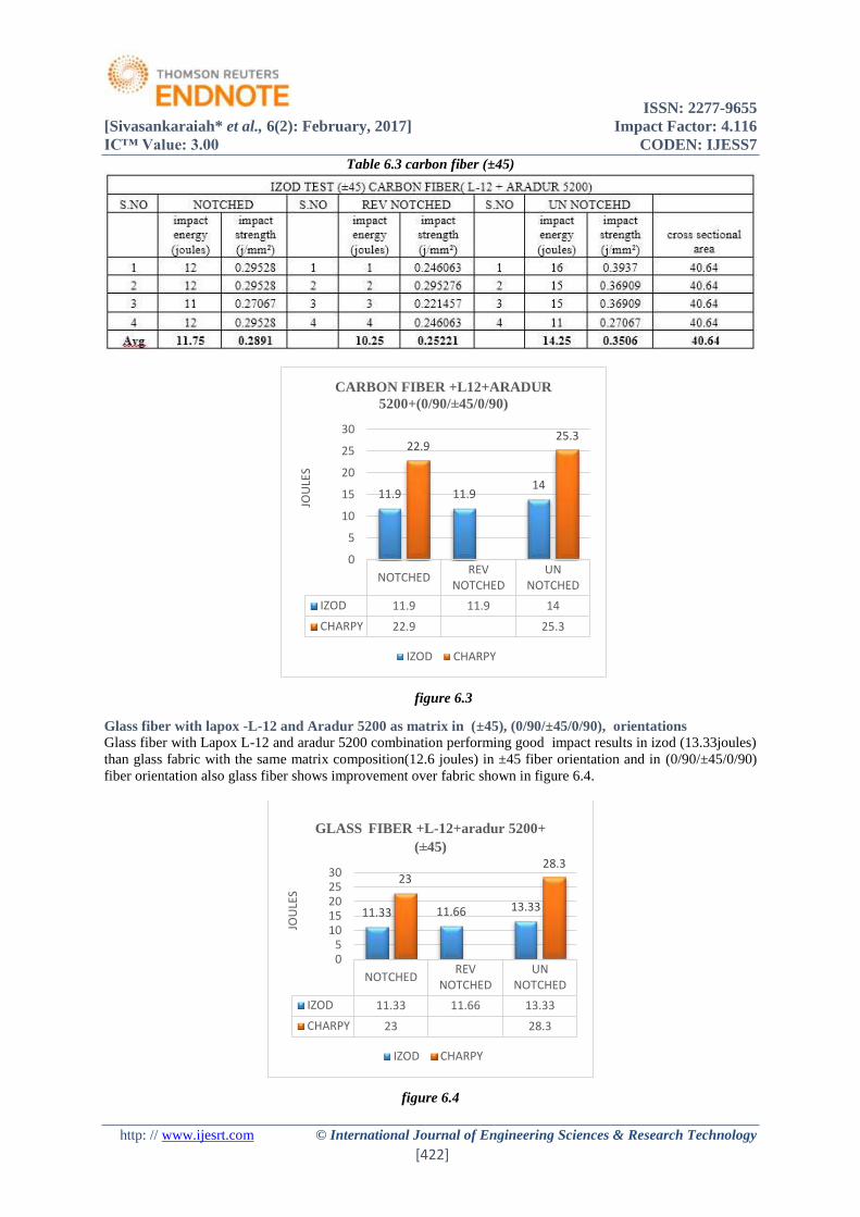
ISSN 2277-9655
[Sivasankaraiah et al 6(2) February 2017] Impact Factor 4116
ICtrade Value 300 CODEN IJESS7
http wwwijesrtcom copy International Journal of Engineering Sciences amp Research Technology
[423]
CONCLUSIONS 1 In the present investigation on impact characteristics of polymer matrix composites depends upon
reinforcement orientation of the reinforcement and matrix composition
2 The characterization was carried among three reinforcements glass fabric glass fiber carbon fiber and
three orientations that is (090)(090plusmn45090) (plusmn45) with different matrix systems (lapox L-12+ K-
6) (lapox L-12+ aradur 5200)
3 Carbon fiber with (plusmn45) orientation in composition of Lapox L-12+ Aradur 5200 giving best in both izod
and chary impact characteristics
4 Glass fiber in (plusmn45) orientation in composition of Lapox L-12+ Aradur 5200 giving approximate results
with carbon fiber in both izod and chary impact characteristics
5 Glass fabric with (lapox L-12+ K-6) in (090) orientation giving lowest izod impact result
6 In (090plusmn45090) orientation the reinforcement giving intermediate results of reinforcement in (090)
(plusmn45) in respective matrix composition
REFERENCES [1] httpwikipediaorgwikiinteoduction to composite materials
[2] httpenwikipediaorgwikiclassification of composite materials
[3] httpenwikipediaorgwikitypes of fibre reinforcements
[4] httpenwikipediaorgwikitypes of matrix materials
Related Documents


