IMCO SCX SERIES INFORMATION, OPERATION & MAINTAINANCE 1. SCX & SCX4 Drives will not fit on a standard gimbal helmet, IMCO HELMET: #05-8025 Black or #05-8027 Silver or #05-8028 ITS Black is required. 2. Maximum engine idle speed is 800 RPM. Shift drive with a positive move, do not let clutch sit between neutral and in gear position. 3. Do Not install propeller until the drive shift linkage has been properly installed and tested with the engine running! 4. When using SCX or SCX4 drives it is necessary to have full hydraulic steering for your safety. 5. When tuning engine remove propeller and shift drive into forward gear! 6. Do not run your boat with a worn or loose gimble ring or helmet, worn clevis pins, or clevis bushings. 7. Every hull is different and requires a different setup: Many different things contribute to performance: water pickup location, cavitation plates, gear ratio, drive height, prop, weight distribution, water conditions, weather conditions. 8. If you are installing the drive on a new application, consult the manufacture or a dealer with experience with the hull to determine the proper drive height. 9. SCX Drive is 19 7/8” from crankshaft center line to prop shaft center line (2” shorter than standard Bravo). SCX4 Drive is 17 7/8” from crankshaft center line to propshaft center line (4” shorter than standard Bravo). 10. The bolt pattern is different from the SCX to the SCX4, lowers cannot be interchanged. 11. Max propeller diameter on the SCX is 16 3/4”, SCX4 is 17” (always check that there is at least 1/2” clearance between the propeller blades and the drive case. 12. Large diameter propellers installed on a #6 prop shaft will require a torque tab on single engine boats. 13. SCX and SCX4 drives require a drive oil reservoir with a minimum capacity of 1 1/2 quarts. 14. When installing drive to gimbal or lower to upper always use anti-seize on all threads 15. When installing lower to upper, inspect all “O” rings, replace as necessary, pressure check to insure proper seal. 16. If you do your own maintenance and repairs on your IMCO drive, you will need a service manual and the proper tools. Service manuals and tools are available at www.imcomarine.com/cal_store. 17. Always wear proper safety equipment when operating your boat, testing or running at high speeds. 18. Inspect for: oil level in drive and reservoir, leaks, loose fasteners, worn parts. Warning! Warning! Warning! Danger! Warning! Warning! Before Runnng!

Welcome message from author
This document is posted to help you gain knowledge. Please leave a comment to let me know what you think about it! Share it to your friends and learn new things together.
Transcript

IMCO SCX SERIES INFORMATION, OPERATION & MAINTAINANCE
1. SCX & SCX4 Drives will not fit on a standard gimbal helmet, IMCO HELMET:#05-8025 Black or #05-8027 Silver or #05-8028 ITS Black is required.
2. Maximum engine idle speed is 800 RPM. Shift drive with a positive move, do not let clutch sit between neutral and in gear position.
3. Do Not install propeller until the drive shift linkage has been properly installed and tested with the engine running!
4. When using SCX or SCX4 drives it is necessary to have full hydraulic steering for your safety.
5. When tuning engine remove propeller and shift drive into forward gear!
6. Do not run your boat with a worn or loose gimble ring or helmet, worn clevis pins, or clevis bushings.
7. Every hull is different and requires a different setup: Many different things contribute to performance:water pickup location, cavitation plates, gear ratio, drive height, prop, weight distribution, water conditions,weather conditions.
8. If you are installing the drive on a new application, consult the manufacture or a dealer with experiencewith the hull to determine the proper drive height.
9. SCX Drive is 19 7/8” from crankshaft center line to prop shaft center line (2” shorter than standard Bravo). SCX4 Drive is 17 7/8” from crankshaft center line to propshaft center line (4” shorter than standard Bravo).
10. The bolt pattern is different from the SCX to the SCX4, lowers cannot be interchanged.
11. Max propeller diameter on the SCX is 16 3/4”, SCX4 is 17” (always check that there is at least 1/2” clearance between the propeller blades and the drive case.
12. Large diameter propellers installed on a #6 prop shaft will require a torque tab on single engine boats.
13. SCX and SCX4 drives require a drive oil reservoir with a minimum capacity of 1 1/2 quarts.
14. When installing drive to gimbal or lower to upper always use anti-seize on all threads
15. When installing lower to upper, inspect all “O” rings, replace as necessary, pressure check to insureproper seal.
16. If you do your own maintenance and repairs on your IMCO drive, you will need a service manual and theproper tools. Service manuals and tools are available at www.imcomarine.com/cal_store.
17. Always wear proper safety equipment when operating your boat, testing or running at high speeds.
18. Inspect for: oil level in drive and reservoir, leaks, loose fasteners, worn parts.
Warning!
Warning!
Warning!
Danger!
Warning!
Warning!
Before Runnng!

Recommended oil: Torco RTF GL-6 (Torco Part #A220015CE (unit) Part # S220015C (case) IMCO Part #09-2600 (unit) Part # 09-2605 (5 Gal.) Part # 09-2610 (case) (100% Synthetic Raceing Transmission Fluid)Replaces SAE 75W90.
To drain oil: remove drain screws from bearing carrier (right below the prop shaft) and on port side of upper.
To replace oil: pump oil in from lower drain screw until it comes out of upper drain screw hole. Replace drainscrews and add oil to drive oil reservoir.
When changing oil, run the used oil through a strainer to check for metal particles, if ther are metal particles in the oil it is time for inspection of the gears and bearings. If oil appears milky or off colored checkfor leaks.
SCX, SCX4 capacity: 5 qts + reservoir - SCX Upper with SC Lower 4 1/2 qts + reservoir.
19. Drive must be turning before shifting.
20. Do not run engine when drive is trimmed extremely high, or in trailer tow mode.
21. Do not use solvents or chemical cleaners to clean painted surfaces on the drive.
22. When installing or changing propeller use extreme caution, propeller blades can be very sharp.
23. SCX upper vertical shaft is 17 tooth spline, SC, Merc lowers are 15 tooth spline. A 17-15 tooth coupler is available 01-2150 (cannot be used with a spacer).
24. Use extreme caution if modifying lower, case can be weakened or handling canbe adversely affected.
25. Break in: Do not use full throttle until drive is fully warmed up, do not hold drive at wide open throttle formore than 2 minutes for the first 3 hours of use.
26. Inspect anode (located on front of cavitation plate) for corrosion or debris; if necessary clean or replace.
27. Do not shift drive while running on hose with propeller installed.
28. Rotation: shift linkage pushed in - right hand rotation, shiftlinkage pulled out - left hand rotation.
29. Serial # location: Port side below SCX, SCX4 sticker3/10/14
SCX Upper & SCX Lower New Break in20 hours
After Break In80 hours
SCX4 Upper & SCX4 Lower New Break in20 hours
New Break in20 hoursSCX Upper & SC Lower
After Break In80 hours
Check Drain Plug MagnetEvery 20 Hours
Warning!
Warning!
Caution!
Danger!
Caution!
Caution!

XXXTREMEADVANTAGE
scscX-X-scscParts and Service Manual
IMCO510 East Arrow HighwaySan Dimas, CA 91773
(800) 899-8058 (909) 592-6162 Fax (909) 592-6052www.imcomarine.com email [email protected]

TABLE OF CONTENTS
Upper Gear Case - Disassembly 1Upper Case Hardware & Seals (Drawing) 2Upper Case Hardware & Seals (Parts List) 3Upper Case Gear & Components (Drawing) 4Upper Case Gear & Components (Parts List) 5Upper Gear Case Assembly 6Upper Gear Case Assembly Cont. 7SCX Setup Diagrams 8SCX Setup Work Sheet 9Backlash Assembly (Diagram) 10Lower Gear Case-Disassembly 11Lower Gear Case (Drawing) 12Lower Gear Case (Parts List) 13Lower Gear Case-Assembly 14Lower Pinion Height Measurments 15Dissassembly-Assembly Tools 16
02/15/10 Rev 1
Serial NumberDate of PurchasePurchased From
Check Oil Before Running
First break in oil change 5-8 hours. Oil is filled to upper drain screw [Fig 1-33]
Pump oil from bottom drain screw [Fig 6-32]
Recommended oil change intervals 20-30 hours. Heavy use or high HP change more often.

UPPER GEAR CASE-DISASSEMBLY NOTE; The following instructions assume that the drive has been removed from the transom assembly and is shifted to the “neutral” position. The lower unit has also been removed, along with the yoke coupler end, center socket, and cross and bearings. Steps followed by asterisk (**) are required only if inspection indicates component replacement. Brackets following the part name represent the drawing figure # and item #.
1. Remove upper cap screws [1-7,8], remove upper cap [1-3]. 2. Remove steering cap screws [1-28], remove steering cap [1-2] 3. Remove detent kit from steering cap [1-31]. 4. Remove cotter key [2-23]. 5. Remove shift link [2-24], shift cable retainer [2-21], shift arm [2-22]. (Shift link
removes out front of gear case).** 6. Remove shift shaft screws [2-27]. 7. Remove shift shaft plug [1-9], shift shaft [2-26], yoke & cam [2-28]. 8. Remove pinion hub screws [1-(22,23)]. 9. Remove pinion hub assembly [2-(31-45)]. 10. Disassemble pinion hub assembly. 11. Remove yoke nut [2-36], and washer [2-37]. 12. Remove yoke [2-32]. 13. Remove retainer nut [2-31]. 14. Remove Yoke gear end shims [2-42], pinion shoulder washer [2-43], and pinion
seal carrier [2-45]. 15. Remove bearings [2-(38,41)], bearing cups [2-(39,40)], and pinion gear [2-12].
Note; be sure to maintain correct assembly position of the upper & lower thrust bearings & races.
16. Remove upper thrust race [2-6], and upper thrust bearing [2-7]. 17. Remove gear assembly [2-(7-17)]. 18. Disassemble gear assembly, press down on upper clutch gear to release the
clutch shaft retainer keepers and remove all components from the clutch shaft. 19. Remove lower thrust race [2-6], lower thrust bearing [2-7]. 20. Remove oil tank cover [1-43], inspect magnet [1-40].
Page 1

Page 2
Upper Case Hardware & SealsFig-1
Item Description Qty Part Number1 Upper Case Black 1 01-1550
1A Upper Case Silver 1 01-15572 Steering Cap CA Black 1 01-1551
2A Steering Cap NV Black 1 01-15522B Steering Cap Generic Black 1 01-15532C Steering Cap ITS Black 1 01-15542D Steering Cap Tie Bar Starboard Black 1 01-15552E Steering Cap Tie Bar Port Black 1 01-1556

Page 3
Upper Case Hardware & SealsFig-1
Item Description Qty Part Number2F Steering Cap CA Silver 1 01-15582G Steering Cap NV Silver 1 01-15592H Steering Cap Generic Silver 1 01-15602I Steering Cap ITS Silver 1 01-15612J Steering Cap Tie Bar Starboard Silver 1 01-15622K Steering Cap Tie Bar Port Silver 1 01-15633 Upper Cap 1 01-25554 Pinion Hub 1 01-25605 Screw (5/16-18 x 1/2" Button Head) 1 08-0407050416 Top Cap Lid 1 01-20717 Screw (3/8-16 x 1 3/4" S/S 12 Point) 4 08-0708061118 Screw (3/8-16 x 1 1/2" S/S 12 Point 4 08-0708061019 Shift Shaft Plug 1 11-1024
10 Quad Ring (Cooling Water, Bottom) 1 11-402411 Screw (5/16-18 x 1/2" Allen Set)(Tower Retainer) 1 08-05070504112 Quad Ring (Cooling Water, Top) 1 11-402513 "O" Ring (Top Cap) 1 11-204914 "O" Ring (Top Cap Oil Pressure) 1 11-201315 Spring Kit (Seal,Ball & Spring) Kit 01-204516 "O" Ring (Water Passage-Upper to Gimbal) 1 11-214817 "O" Ring (Shift Linkage) 1 11-212918 Pinion Hub Shims Kit 01-254819 "O" Ring (Pinion Hub) 2 11-216120 "O" Ring (Pinion Retainer Nut) 1 11-215421 Pinion Hub (5/16" Copper Sealing Washers) 10 08-12070000422 Screw (5/16-18 x 1" Socket Cap) 4 08-06070508223 Screw (5/16-18 x 1 1/2" Socket Cap) 6 08-06070510224 Screw (3/8-16 x 3/4" HH) 2 08-01080606125 Washer (3/8" Star) 2 08-11080000126 Washer (3/8" AN) 2 08-10080000127 Anode 1 01-206728 Screw (7/16-14 x 1 3/4" S/S 12 Point) 4 08-07090711129 "O" Ring (Steering Cap, Oil) 1 11-225030 "O" Ring (Steering Cap, Shift Cavity) 1 11-224231 Detent Kit (Spring & Ball Cylinder) Kit 01-204432 Drain Screw Sealing Washer 1 11-101733 Drain Screw 1 01-250434 Guide Pads (Port & Starboard) 2 01-247135 Screw (1/4-20 x 1/2" Flat Head Undercut) 4 08-02060404136 Stud (7/16 x 2 1/2") 4 08-13090414137 Washer (7/16" AN S/S) 4 08-10090000138 Nut (7/16-20 Nylock S/S) 4 08-08090400139 Screw (10-24 x 5/8" Socket Cap) 1 08-06040305240 Magnet 1 01-958741 Screw (1/4-20x 5/8" Socket Cap) 8 08-06060405142 Oil Tank Gasket 1 11-103043 Oil Tank Cover 1 01-2574

Page 4
Upper Case Gear & ComponentsFig-2

Item Description Qty Part Number1 Upper Case Black 1 01-1550
1A Upper Case Silver 1 01-15572 Roller Bearing (Clutch Shaft Cap) 1 10-30423 Upper Cap 1 01-25554 Pinion Hub 1 01-25605 Tower Race 2 10-60416 Thrust Race 2 10-5045-X7 Thrust Bearing (Gear) 2 10-40448 Keepers (Clutch Shaft) 2 01-20479 Clutch Shaft Retainer (Thrust Collar) 1 01-2189
10 Spirol Retainer Ring 2 01-205511 Roller Bearing (Internal Gear) 2 10-304612 SCX Pinion Gear 1 01-453813 SCX Clutch Gear 2 01-453914 Thrust Bearing (Clutch Spring) 2 10-402015 Clutch Spring 2 01-205616 SCX Clutch 1 01-256217 SCX Clutch Shaft 1 01-355618 Pinion Hub Shims Kit 01-2548-X19 Roller Bearing (Clutch Shaft Tower) 1 10-304320 SCX Tower 1 01-256121 SCX Shift Cable Retainer 1 01-257322 SCX Shift Arm 1 01-157823 Cotter Key 1 08-15020014124 SCX Shift Link 1 01-157725 Shift Shaft Bushing 1 10-701826 SCX Shift Shaft 1 01-355927 Screw (1/4-28 x 3/4" Socket Cap) 2 08-06060206228 Yoke & Cam 1 01-809529 Seal, Shift Shaft 2 11-303030 Shift Shaft Bushing 1 10-701931 Retainer Nut 1 01-223932 Yoke Gear End 1 01-208533 Cross & Bearing 2 01-208634 Center Socket 1 01-208735 Yoke Coupler End 1 01-208836 Nut (Yoke Gear End)(5/8-18 Thin Nylock Steel) 1 08-09110500237 Washer (Yoke Gear End) 1 08-12110000238 Bearing Cone (Pinion Bearing) 1 10-102139 Bearing Cup (Pinion Bearing) 1 10-202240 Bearing Cup (Pinion Bearing) 1 10-202441 Bearing Cone (Pinion Bearing) 1 10-102342 Yoke Gear End Shims Kit 01-2020-X43 Pinion Shoulder Washer 1 01-224144 Yoke Gear End Seal 1 11-302945 Pinion Seal Carrier 1 01-2240
Page 5
Upper Case Gear & ComponentsFig-2

UPPER GEAR CASE-ASSEMBLY NOTE; Optimum performance of the upper gear case requires “setting up” the pinion & clutch gears with IMCO procedure as follows.
1. Take all measurements using the “SCX Setup Diagrams” (Fig 3) and the “SCX Work Sheet” (Fig 4).
2. After all measurements are taken and proper race thickness has been determined, place lower race [2-6] and thrust bearing [2-7] in case.
3. Place lower clutch gear [2-13] with attached tool (backlash tower 01-5579) into case.
4. Adjust rolling preload (8-10 in/lbs) on pinion gear by changing Yoke Gear End Shims [2-42]. Tighten nut [2-36] to 75 ft/lbs.
5. After proper rolling preload is determined, assemble pinion pack with pinion retainer nut “O” ring [1-20] between pinion seal carrier [2-45] and retainer nut [2-31].
6. Torque retainer nut to 200 ft/lbs. ((Tool: Pinion Retainer Nut Driver 01-5590) (torque wrench centered on retainer nut or if using longer tool be sure to compensate on torque value). Use new lock nut [2-36] and torque to 75 ft/lbs.
7. Install pinion pack using 4 screws [1-23] for testing. 8. Install dial indicator (indicator bracket 01-5588) and pinion gear locking tool
(pinion gear lock 01-5587) Fig-5. 9. Check backlash, adjust backlash with pinion hub shims [2-18] (average backlash
should be .006-.008. 10. Once backlash is determined check upper clutch gear by placing gear in lower
position with lower thrust race and backlash tower. This will insure backlash is .006 -.008 is correct on upper gear.
11. Assemble drive shaft gear assembly [2-(8-17)]. 12. Place the lower clutch gear [2-13] onto the clutch shaft [2-17], allowing it to rest
on the thrust collar. 13. Place the lower clutch spring thrust bearing [2-14] (silver side “up), lower clutch
spring [2-15], clutch cone [2-16], upper clutch spring [2-15], upper clutch spring thrust bearing [2-14], (Note; use a thin layer of grease between the bearing and the gear to keep bearing in place during assembly), (silver side “down”), upper clutch gear [2-13], clutch shaft retainer [2-9] onto the upper clutch shaft [2-17].
14. Compress the upper clutch gear and install the upper drive shaft retainer keepers [2-8].
15. Install complete clutch shaft assembly into gear case. 16. Align the clutch gear timing marks (“+” over “-“, or “-“ over “+”) with the center of
the rear face of the gear case. 17. Install pinion pack with “O” ring [1-19] and shims [2-18] (shims must be properly
aligned). 18. Torque pinion pack screws [1-(22-23)] (important: make sure copper sealing
washers [1-21] are in place, short screws in 2 top holes & 2 bottom holes [1-22] longer screws in 3 port & 3 starboard holes [1-23] to 20 ft/lbs. Use “Loctite 242” on all screws. Note: make sure that the clutch gear timing marks align to case timing marks, roll pinion to check.
Page 6
UPPER GEAR CASE-ASSEMBLY
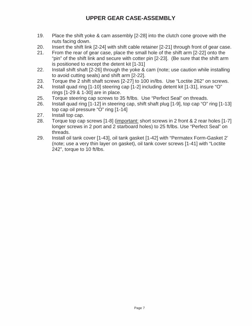
19. Place the shift yoke & cam assembly [2-28] into the clutch cone groove with the nuts facing down.
20. Insert the shift link [2-24] with shift cable retainer [2-21] through front of gear case. 21. From the rear of gear case, place the small hole of the shift arm [2-22] onto the
“pin” of the shift link and secure with cotter pin [2-23]. (Be sure that the shift arm is positioned to except the detent kit [1-31]
22. Install shift shaft [2-26] through the yoke & cam (note; use caution while installing to avoid cutting seals) and shift arm [2-22].
23. Torque the 2 shift shaft screws [2-27] to 100 in/lbs. Use “Loctite 262” on screws. 24. Install quad ring [1-10] steering cap [1-2] including detent kit [1-31], insure “O”
rings [1-29 & 1-30] are in place. 25. Torque steering cap screws to 35 ft/lbs. Use “Perfect Seal” on threads. 26. Install quad ring [1-12] in steering cap, shift shaft plug [1-9], top cap “O” ring [1-13]
top cap oil pressure “O” ring [1-14] 27. Install top cap. 28. Torque top cap screws [1-8] (important: short screws in 2 front & 2 rear holes [1-7]
longer screws in 2 port and 2 starboard holes) to 25 ft/lbs. Use “Perfect Seal” on threads.
29. Install oil tank cover [1-43], oil tank gasket [1-42] with “Permatex Form-Gasket 2’ (note; use a very thin layer on gasket), oil tank cover screws [1-41] with “Loctite 242”, torque to 10 ft/lbs.
Page 7

Page 8
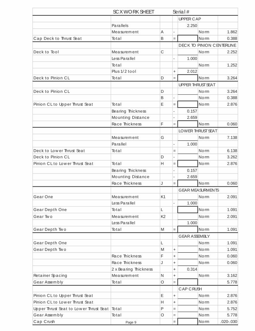
UPPER CAPParallels 2.250Measurement A - Norm 1.862
Cap Deck to Thrust Seat Total B = Norm 0.388DECK TO PINION CENTERLINE
Deck to Tool Measurement C Norm 2.252Less Parallel - 1.000Total Norm 1.252Plus 1/2 tool + 2.012
Deck to Pinion CL Total D = Norm 3.264UPPER THRUST SEAT
Deck to Pinion CL D Norm 3.264B - Norm 0.388
Pinion CL to Upper Thrust Seat Total E = Norm 2.876Bearing Thickness - 0.157Mounting Distance - 2.659Race Thickness F = Norm 0.060
LOWER THRUST SEATMeasurement G Norm 7.138Parallel - 1.000
Deck to Lower Thrust Seat Total = Norm 6.138Deck to Pinion CL D - Norm 3.262Pinion CL to Lower Thrust Seat Total H = Norm 2.876
Bearing Thickness - 0.157Mounting Distance - 2.659Race Thickness J = Norm 0.060
GEAR MEASURMENTSGear One Measurement K1 Norm 2.091
Less Parallel - 1.000Gear Depth One Total L Norm 1.091Gear Two Measurement K2 Norm 2.091
Less Parallel 1.000Gear Depth Two Total M = Norm 1.091
GEAR ASSEMBLYGear Depth One L Norm 1.091Gear Depth Two M + Norm 1.091
Race Thickness F + Norm 0.060Race Thickness J + Norm 0.0602 x Bearing Thickness + 0.314
Retainer Spacing Measurement N + Norm 3.162Gear Assembly Total O = 5.778
CAP CRUSHPinion CL to Upper Thrust Seat E + Norm 2.876Pinion CL to Lower Thrust Seat H + Norm 2.876Upper Thrust Seat to Lower Thrust Seat Total P = Norm 5.752Gear Assembly Total O = Norm 5.778Cap Crush = Norm .020-.030
SCX WORK SHEET Serial #
Page 9

Backlash AssemblyFig-5
Page 10

LOWER GEAR CASE – DISASSEMBLY
Note; The following instructions assume that the lower unit has already been separated from the upper gearhead. Steps followed by asterisks (**) are required only if inspection indicates component replacement. Brackets following the part name represent the drawing figure # and item #.
1. Bend the tabs of the bearing carrier tab washer [6-31] away from the bearing carrier retainer nut [6-30].
2. Remove the bearing carrier retainer nut [6-30]. 3. Remove the bearing carrier [6-34]. 4. Remove the prop shaft [6-27]. (The prop shaft bushing [6-26], used only with the
01-8244 & 01-8248 gear sets, may come out with the prop shaft). 5. Remove the bearing carrier “O” ring [6-38], shims [6-39], & thrust washer [6-40]. 6. Remove the vertical shaft flange nut [6-29]. 7. Remove “O” ring [6-13], & alignment spacer [6-14], shims [6-15], & tab washer
[6-16]. 8. Remove the vertical shaft [6-2] (with bearings) & pinion gear [6-25]. 9. Remove the prop gear [6-25], (with bearing). (The prop shaft bushing [6-26] may
be removed from the gear at this time, if it was not removed in step #4). 10. Remove the lower vertical shaft bearing cup [6-20], & shims [6-21]. 11. Remove the vertical shaft roller bearing [6-28]. ** 12. Remove the upper [6-18], & lower [6-19] bearing cones from the vertical shaft. ** 13. Remove the roller bearing race [6-3] from the vertical shaft. ** 14. Remove the bearing cup [6-36] from the bearing carrier. ** 15. Remove the prop shaft seals [6-35] from the bearing carrier. ** 16. Remove the prop gear bearing cone [6-24] from the prop gear. ** 17. Remove the prop gear bearing cup [6-23], & shims [6-22]. ** 18. Remove the bearing cone [6-37] from the prop shaft. ** 19. Remove the “O” ring [6-6]. “O” ring [6-7], & “O” ring [6-8]. **
Page 11

Lower Gear CaseFig-6
Page 12

Description Qty Part Number1 Lower Case (-0) Standard Length 1 01-1120
1A Lower Case (-1") Shorter 1 01-11211B Lower Case (-2") Shorter 1 01-11222 Vertical Shaft-Standard Length (17 Tooth) 1 01-3265
2A Vertical Shaft-1" Shorter (17 Tooth) 1 01-32662B Vertical Shaft-2" Shorter (17 Tooth) 1 01-32673 Bearing Race 1 10-60054 Nut (7/16-20 Nylock S/S Thin) 2 08-0909040015 Washer ((7/16" AN S/S Thin) 2 08-1609000016 "O" Ring (Oil Passage) 1 11-40117 "O" Ring (Water Passage) 1 11-21438 "O" Ring (Cooling Water Passage) 1 11-20149 Pipe Plug - 1/8 NPT S/S 1 09-200710 Stud (7/16 x 2" S/S) 2 08-13090412111 Retainer Ring (Vertical Shaft Coupler) 1 08-12150000112 Vertical Shaft Coupler (17 Tooth) 1 01-214013 "O" Ring (Alignment Spacer) 1 11-222814 Alignment Spacer 1 01-201515 Shim (Vertical Shaft Upper) Kit 01-201216 Tab Washer (Vertical Shaft) 1 01-204317 Bearing Cup (Vertical Shaft Upper) 1 10-201218 Bearing Cone (Vertical Shaft Upper) 1 10-101119 Bearing Cone (Vertical Shaft Lower) 1 10-101020 Bearing Cup (Vertical Shaft Lower) 1 10-200921 Shim (Vertical Shaft Lower) 1 01-201322 Shim (Prop Gear) Kit 01-201423 Bearing Cup (Prop Gear) 1 10-200724 Bearing Cone (Prop Gear) 1 10-100825 Prop & Pinion Gear 1:50 Set 01-8240
25A Prop & Pinion Gear 1:34 Set 01-824425B Prop & Pinion Gear 1:25 Set 01-824826 Bushing - Prop Shaft, -X 1 01-217827 Prop Shaft, 1" 1 01-3009
27A Prop Shaft, 1 1/4" 1 01-301027B Prop Shaft, 1 7/16" 1 01-357028 Bearing (Roller) 1 10-300629 Nut (Pinion Gear) 1 01-225130 Cover Nut 1 01-206531 Tab Washer (Bearing Carrier) 1 01-204232 Drain Screw 1 01-250433 Drain Screw Sealing Washer 1 11-101734 Bearing Carrier (1" Prop Shaft) 1 01-2130
34A Bearing Carrier (1 1/4" Prop Shaft) 1 01-213134B Bearing Carrier (1 7/16" Prop Shaft) 1 01-257535 Seal (Prop Shaft 1") 1 11-3035
35A Seal (Prop Shaft 1" Line Cut) 1 11-303235B Seal (Prop Shaft 1 1/4") 2 11-303335C Seal (Prop Shaft 1 7/16") 2 11-303436 Bearing Cup (I" Prop Shaft) 1 10-2014
36A Bearing Cup (1 1/4" Prop Shaft) 1 10-201636B Bearing Cup (1 7/16" Prop Shaft) 1 10-201837 Bearing Cone (1" Prop Shaft) 1 10-1013
37A Bearing Cone (1 1/4" Prop Shaft) 1 10-101537B Bearing Cone (1 7/16" Prop Shaft) 1 10-101738 "O" Ring (Bearing Carrier) 1 11-234439 Shim (Bearing Carrier) Kit 01-201140 Thrust Washer (.109 Thick) 1 01-2042
Lower Gear Case Fig-6
Page 13

LOWER GEAR CASE - ASSEMBLY
Note; Optimum performance of lower gears requires pinion height setup, use “ Lower Pinion Gear Height Measurement” (Fig. 7) sheet to set pinion gear.
1. Install the vertical shaft roller bearing [6-28] into the gear case. 2. Install the vertical shaft lower bearing cup [6-20], & shims [6-21]. 3. Install the lower [6-19], upper [6-18] bearing cones, and roller bearing race [6-3]
onto the vertical shaft [6-2]. 4. Install the vertical shaft into the gear case. 5. Install the upper bearing cup [6-17]. Tab washer [6-16], shims [6-15], & alignment
spacer [6-14] onto the vertical shaft. 6. Install the vertical shaft clamp plate onto the gear case. (Mercury Part # 43559T) 7. Check the rolling torque of the vertical shaft (optimum 3 to 5 lb/in). 8. Adjust the thickness of the upper shim to obtain the correct rolling torque. 9. Temporarily install the pinion gear [6-25], & flange nut [6-29]. 10. Check the pinion gear height (optimum .025) (see “Lower Pinion Height
Measurement” (Fig. 7) 11. If pinion gear height requires correction remove all associated components and
adjust the lower bearing shims. Any adjustment here requires that the upper bearing shims be compensated by the same amount.
12. Remove the vertical shaft & pinion. 13. Install the prop gear bearing shims [6-22], & bearing cup [6-23] into the gear case. 14. Install the prop gear bearing cone [6-24] onto the prop gear [6-25]. 15. Install the prop gear with bearing into the gear case. (The prop shaft bushing
[6-26], used only with the 01-8244 and 01-8248 gear sets, must be installed into the prop gear at this time).
16. Re-install the vertical shaft components described above, and install the vertical shaft clamp plate.
17. Install the bearing carrier bearing cone [6-37] onto the prop shaft. 18. Install the prop shaft with bearing into the gear case. 19. Install the prop shaft seals [6-35], & bearing carrier bearing cup [6-36] into the
bearing carrier [6-34]. 20. Temporarily install the bearing carrier into the gear housing. 21. Install the bearing carrier tab washer [6-31], & retainer nut [6-30], and torque the
retainer nut to 150 lb/ft. 22. Rotate the vertical shaft at least 3 turns and check the prop gear backlash
(optimum .012 to .015). 23. Adjust the thickness of the prop gear bearing cup shims [6-22] to obtain the correct
backlash readings. 24. During final assembly be sure to clean & loctite the vertical shaft flange nut [6-29].
Torque the nut to 100 lb/ft. 25. Temporarily install the bearing carrier thrust washer [6-40], & shims [6-39] prior to
prop shaft & bearing carrier installation. 26. Torque the bearing carrier retainer nut to 150 lb/ft. 27. Check overall rolling torque at the vertical shaft (optimum 11 to 17 lb/in).
Page 14

LOWER GEAR CASE – ASSEMBLY CONT.
28. Adjust the thickness of the bearing carrier shims [6-39] to obtain the correct rolling torque readings.
29. Upon final assembly be sure to install the bearing carrier “O” ring [6-38] prior to installation of the bearing carrier.
30. After applying final torque of the bearing carrier retainer nut [6-30], bend one tab of the tab washer [6-31] to engage with one of the slots in the retainer nut.
Lower Pinion Height MeasurementFig-7
Page 15

Disassembly-Assembly Tools
SCX Upper
IMCO Mercury 1. Tower & Cap Race Puller Kit 01-5443 2. Tower Internal Bearing Puller Kit 01-5445 3. Tower Removal Tool Kit 01-5448 4. Pinion Retainer Nut Driver 01-5590 5. Pinion Center Measuring Slug 01-5583 6. Pinion Bearing Cup Installer (Front) 01-5580 7. Pinion Bearing Cup Installer (Back) 01-5581 8. Bearing & Race Installer (Cap) 01-5581 9. Bearing & Race Installer (Tower) 01-5582 10. Backlash Tool Kit 01-8017 A. Backlash Tower 01-5579 B. Indicator Bracket 01-5588 C. Pinion Gear Lock 01-5587 D. Backlash Wand 01-5449 E. Dial Indicator 01-5591
SC Lower 1. Cover Nut Wrench (1” Prop Shaft) 91-61069T 2. Cover Nut Wrench (1 ¼” Prop Shaft) 91-840393 3. Lower Pinion Height Gauge 91-42840 4. Prop Gear Cup Installer 91-31106 5. Vertical Shaft Roller Bearing Driver A. Pilot 91-813653 B. Driver rod 91-37323 C. Bearing Remover 91-638T 6. Vertical Shaft Roller Bearing Installer A. Pilot 91-813653 B. Threaded Rod 91-31229 C. Bearing Installer 91-89867 7. Clamp Plate 91-43559T 8. Dial Indicator 91-58222A1 9. Vertical Shaft Bearing Cup Puller 01-5409 10. Prop Gear Cup Puller 01-5410 11. Bearing Carrier Cup & Seal Installer (1 ¼”) 01-5411
Related Documents