HAL Id: hal-02867315 https://hal.archives-ouvertes.fr/hal-02867315 Submitted on 14 Jun 2020 HAL is a multi-disciplinary open access archive for the deposit and dissemination of sci- entific research documents, whether they are pub- lished or not. The documents may come from teaching and research institutions in France or abroad, or from public or private research centers. L’archive ouverte pluridisciplinaire HAL, est destinée au dépôt et à la diffusion de documents scientifiques de niveau recherche, publiés ou non, émanant des établissements d’enseignement et de recherche français ou étrangers, des laboratoires publics ou privés. Imaging, Stereotactic Space and Targeting Armando Alaminos-Bouza To cite this version: Armando Alaminos-Bouza. Imaging, Stereotactic Space and Targeting. Arthur Cukiert. Functional Neurosurgery, Alaúde Editorial., pp.67-79, 2014, 978-85-7881-248-5. hal-02867315

Welcome message from author
This document is posted to help you gain knowledge. Please leave a comment to let me know what you think about it! Share it to your friends and learn new things together.
Transcript

HAL Id: hal-02867315https://hal.archives-ouvertes.fr/hal-02867315
Submitted on 14 Jun 2020
HAL is a multi-disciplinary open accessarchive for the deposit and dissemination of sci-entific research documents, whether they are pub-lished or not. The documents may come fromteaching and research institutions in France orabroad, or from public or private research centers.
L’archive ouverte pluridisciplinaire HAL, estdestinée au dépôt et à la diffusion de documentsscientifiques de niveau recherche, publiés ou non,émanant des établissements d’enseignement et derecherche français ou étrangers, des laboratoirespublics ou privés.
Imaging, Stereotactic Space and TargetingArmando Alaminos-Bouza
To cite this version:Armando Alaminos-Bouza. Imaging, Stereotactic Space and Targeting. Arthur Cukiert. FunctionalNeurosurgery, Alaúde Editorial., pp.67-79, 2014, 978-85-7881-248-5. hal-02867315
See discussions, stats, and author profiles for this publication at: https://www.researchgate.net/publication/303566448
Imaging, Stereotactic Space and Targeting in Functional Neurosurgery
(correction)
Chapter · February 2014
CITATIONS
0READS
255
1 author:
Some of the authors of this publication are also working on these related projects:
Stereotactic Neurosurgery simulation, planning and post-op View project
Monte Carlo in Radiotherapy Planning View project
Armando Alaminos Bouza
Mevis Informática Médica LTDA
39 PUBLICATIONS 94 CITATIONS
SEE PROFILE
All content following this page was uploaded by Armando Alaminos Bouza on 27 May 2016.
The user has requested enhancement of the downloaded file.

“Functional Neurosurgery”. Editor: Arthur Cukiert. Alaúde Editorial. 2014, pages 67-79.
Imaging, Stereotactic Space and Targeting in Functional Neurosurgery. By Armando Alaminos Bouza
Imaging, Stereotactic Space and Targeting in Functional Neurosurgery.
Author : Armando L. Alaminos Bouza
Introduction.
At the time of this writing, stereotaxis is the safest carrier that neurosurgeons can trust to lead
their instruments into deep seated brain targets.
In contrast with other chapters, this will be more technically centered and far less clinically
oriented. The goal here is to present the instrumentation of stereotactic neurosurgery for all the
potentially involved community, including functional neurosurgeons in the first place but no
exclusively. There are (and have being) other professionals directly committed to the
development of the stereotaxis’ technical framework. Aimed to a heterogeneous audience,
some technicalities will be trimmed, but hoping that the introduction of the problem followed by
the associated reference would guide an in-depth research for those concerned with the
subject.
The instrumentation for stereotactic neurosurgery starts with the stereotactic frames and other
accessories conforming and stereotactic apparatus. The evolution of the stereotactic apparatus
walked a long way to reach the present excellence, but its mutation rate slowed down some
twenty year ago. Precisely some twenty years ago advances in diagnostic imaging and high
performance computing merged into stereotaxis with remarkable success.
The focus of this chapter will be the merging of brain imaging modalities into the stereotactic
framework. Stereotactic neurosurgery was a pioneer modality into the field of image guided
surgery and with that trend came the surgical planning workstation. Surgical planning
workstations brought new options to stereotaxis, such as surgical simulation, trajectory
planning, atlas integration, multimodality image fusion, two dimensional (2D) re-slicing and three
dimensional (3D) rendering, to mention only a few.
Transition from 2D images into 3D stereotactic space.
The development of stereotactic neurosurgery has being deeply linked with the evolution of
medical imaging devices. Any stereotactic procedure depends on a fixed spatial relation
between images with the physical space occupied by the patient during surgery.
Historically, the position of the patient was fixed to a rigid external device that provides a proper
coordinates reference system. The reference system is usually called stereotactic frame. The
stereotactic frame is affixed to the patient skull prior to imaging. A basic principle that must be
obeyed is that the patient’s anatomy does not move, relatively to the stereotactic frame, since
the acquisition of the images until the end of the surgical procedure.
The coordinates associated with the stereotactic frame are usually called stereotactic
coordinates. Stereotactic coordinates specify locations inside the frame or what is also called
stereotactic space. Using stereotactic coordinates, several objects can be aimed into a small
volume of the patient’s brain, such as: needles, electrodes and even high energy photons.
The mathematical relation that maps any pixel of an image into the stereotactic coordinates is
called registration. There are multiples techniques for registration. In the case of stereotactic
neurosurgery the registration is point based. Any stereotactic system includes some form of
localizer, such localizers are known as fiducials markers.
A fiducials marker is an object placed in the field of view of an imaging system which appears in
the image produced, for use as a point of reference or a measure. It may be either something
placed into or on the imaging subject, or a mark or set of marks in the reticle of an optical
instrument.

“Functional Neurosurgery”. Editor: Arthur Cukiert. Alaúde Editorial. 2014, pages 67-79.
Imaging, Stereotactic Space and Targeting in Functional Neurosurgery. By Armando Alaminos Bouza
The position of each fiducial marker is well defined by the system manufacturer and can be
computed for any portion of the marker using geometric relations. Figure 1 shows two of the
most popular stereotactic localizers for computer tomography (CT) or magnetic resonance
images (RMI).
Figure 1a presents the model of the localizer known as "N" shaped. "N" shaped fiducials are
used by several stereotactic systems such as Leksell, CRW, Micromar, Bramsys, FiMe, etc.
Figure 1b shows the schematics of the "V" shaped fiducials, first introduced by Sturm, Pastyr et
al.[1] with a Riechert-Mundinger device and today also used in the Zamorano-Dujovny system
[2].
Fig. 1
Any properly acquired stereotactic image must present a minimum set of fiducial markers. The
minimum number of markers should provide the necessary geometric information that allows full
registration.
An image created by tomographic reconstruction (CT, RMI, PET, SPECT) represents a plane. A
plane is a two dimensional (2D) entity. But stereotactic coordinates specify position in a three
dimensional (3D) space. Therefore, it is necessary a mathematical transformation that takes a
point on the image (pixel in 2D) and computes stereotactic coordinates in 3D. One common
solution to this problem uses homogeneous transformation of the form:
x = a11 * h + a12 * v + a13
y = a21 * h + a22 * v + a23 equ. 1
z = a31 * h + a32 * v + a33
where, v is the vertical position of the pixel over the image space and h is the horizontal
position of the pixel. (x,y,z) represent the stereotactic coordinates for that pixel.
Equation 1 is commonly used in its matrix representation, but for the sake of simplicity the
matrix model will not be treated.
Before using the transformation in equation 1 we must know the values of a11, a12,..a33. To
compute the values of aij it is necessary to know the stereotactic coordinates of at least three
non-collinear pixels over the image. The center of the fiducials have stereotactic coordinates
that are known or can be computed, using the manufacturer specification.
Let us try to find the stereotactic coordinates for the central fiducials of the "N" shaped model.
Figure 2 present the lateral view of one "N" shaped fiducials. The height of each fiducials bar is
H. The dashed line represents the plane of the tomographic image. When the image plane cuts
“Functional Neurosurgery”. Editor: Arthur Cukiert. Alaúde Editorial. 2014, pages 67-79.
Imaging, Stereotactic Space and Targeting in Functional Neurosurgery. By Armando Alaminos Bouza
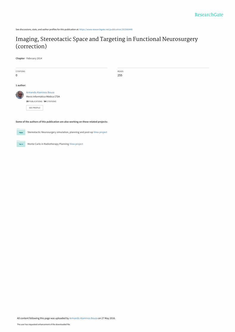
the fiducial, three points are created on the image, they are identified as p1, p2 and p3 in figure
2. Our goal is to determine the 3D coordinates of point p2.
Fig. 2
The distance from p1 to p3 is D and the distance from p2 to p3 is d, both distances are
measured on the image and can be expressed in pixels. Let us consider that the Z axis has
zero at the "N" base and grows in the direction of the top of this page. It can be proved that the
value of z for point p2 is :
z = H * d / D equ. 2
The value of z will carry the same units used to express H, usually mm . An interesting feature
of equation 2 is that result does not depend on the calibration of the imaging device, because
de scale factor comes from the known size of H in the “N” shaped fiducials.
For all the stereotactic systems with "N" shaped fiducials the values of x and y are known by
design for points p1 and p3 (look for these values in the schematics of your stereotactic device
or ask the manufacturer) . If we represent by x1 and x3 the values of x for points p1 and p3
respectively, the value of x for point p2 can be obtained as
x = x3 + (x1 - x3) * d / D equ. 3
and using the same reasoning , the value of y for point p2 is ,
y = y3 + (y1 - y3)* d / D equ. 4
And now the 3D stereotactic coordinates for point p2 are well established. Note that the values
of x,y,z from equations 2, 3, 4 remain valid even if the image plane is not parallel to the base of
the "N" shaped fiducial or the stereotactic frame.
Stereotactic apparatus equipped with "N" shaped fiducials use three of those fiducials, so that
each image presents three points equivalent to p2, which is the minimum information needed to
obtain the values of a11..a33 of equation 1.
Note that each image has a different set of values a11..a3.
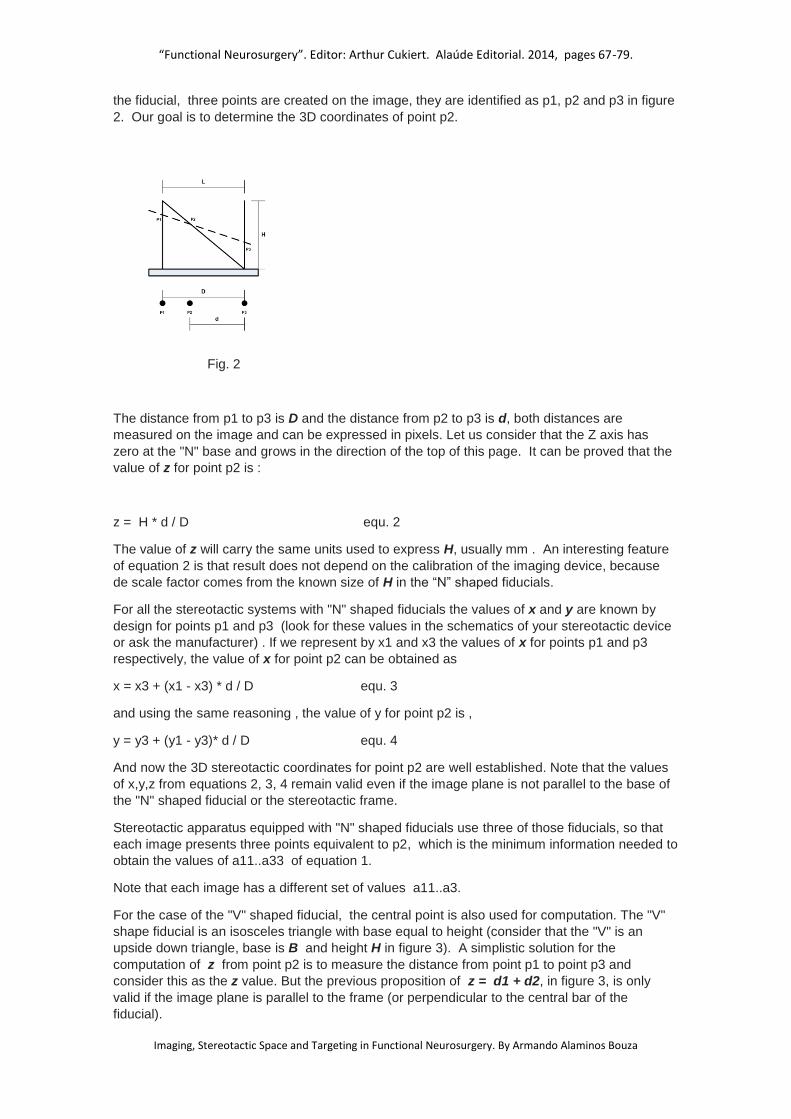
For the case of the "V" shaped fiducial, the central point is also used for computation. The "V"
shape fiducial is an isosceles triangle with base equal to height (consider that the "V" is an
upside down triangle, base is B and height H in figure 3). A simplistic solution for the
computation of z from point p2 is to measure the distance from point p1 to point p3 and
consider this as the z value. But the previous proposition of z = d1 + d2, in figure 3, is only
valid if the image plane is parallel to the frame (or perpendicular to the central bar of the
fiducial).
“Functional Neurosurgery”. Editor: Arthur Cukiert. Alaúde Editorial. 2014, pages 67-79.
Imaging, Stereotactic Space and Targeting in Functional Neurosurgery. By Armando Alaminos Bouza
Fig. 3
A general solution for the computation of z value in p2 is:
z = 4 * d1 * d2 / (5*d1*d1 + 5*d2*d2 - 6 * d1 * d2)1/2 equ. 5
Equation 5 remains valid even in case of oblique image plane, under only one condition: points
(fiducials) p1, p2 and p3 must be identifiable on the image plane. In contrast with equation 2,
the solution of equation 5 depends on accurate calibration of the imaging device.
Values of x and y for point p2 in each image are fixed and well known from the manufacturer.
Each image must show at least three "V" fiducials in order to solve the values of a11..a33 in
equation 1.
The first modality of image used in the early days of stereotactic surgery was the x-ray. An x-ray
image is the result of a projection, all the volume enclosed in the field of view (fov) of the beam
is compressed into the 2D plane of the film. Today, the use of stereotactic x-ray is less popular
but some targets still demand x-ray. The case of arteriovenous malformations (AVM) is a good
example. Some AVMs can be study using CT angiography or MR angiography but there are
those defined only with digital subtraction angiography (DSA).
In the pre-computerized days of stereotactic neurosurgery the use of teleradiography became
common. Two orthogonal x-ray views were needed to solve the coordinates of a point. The
biggest problem with projection images in stereotaxis is the parallax effect. Extending the focus
film distance and keeping the patient close to film the parallax effect is minimized and the
computation of stereotactic coordinates produced good results, only with marginal acceptable
error. That setup demanded very big operating rooms or some tricks, such as the use an old lift
pit to install the x-ray tube at the top and the patient at the bottom of the pit.
Today there are computer algorithms that produce stereotactic coordinates from two or more
projection images in milliseconds, so the teleradiography solution became part of the primeval
history of stereotaxy.

“Functional Neurosurgery”. Editor: Arthur Cukiert. Alaúde Editorial. 2014, pages 67-79.
Imaging, Stereotactic Space and Targeting in Functional Neurosurgery. By Armando Alaminos Bouza
Stereotactic fiducials for x-ray or DSA are not like those for CT or MRI. In figure figure 4 a
typical model is represented.
Fig. 4
There are four markers per fiducial. Each image (x-ray or DSA) needs two of these fiducials at
different distances from the X-ray source, so that eight markers must be visible in the image.
The manufacturer defines the stereotactic coordinates of each fiducial marker.
Using the same formalism of homogeneous transformation, any point inside the stereotactic
space with coordinates (x,y,z) is projected to the film coordinates (h,v)
Ω = c0*x + c1*y + c2*z + 1
Ω*h = c3*x + c4*y + c5*z + c6 equ. 6
Ω*v = c7*x + c8*y + c9*z + c10
Modifying equation 6 to obtain h and v :
h = (c3*x + c4*y + c5*z + c6) / (c0*x + c1*y + c2*z + 1) equ. 7
v = (c7*x + c8*y + c9*z + c10) / (c0*x + c1*y + c2*z + 1)
With equation 7 it is possible to obtain the projection on the film of any point inside the
stereotactic volume if we know the values of c0..c10 . Using the known position of six or more
fiducials in each film we can find the values of c0..c10 for each projection. The mathematical
model expressed with equations 6 and 7 is valid if the projection surface is a plane (flat, without
curvature) and there is no restriction in the angle between the fiducial and the plane.
Note that the inverse problem has infinite solutions, that is: if we know the position of a point P
on one film there are infinite points in 3D that projects into P . The projection of a distal object
onto a flat surface introduces a theoretical problem, described by Berkeley (1790), for the
perceptual reconstruction of the third dimension, namely projective ambiguity. So, to solve the
depth ambiguity two or more non-parallel projections are needed. If the same point in
stereotactic space (anatomy) is identifiable on two or more projections we are able to find its 3D
coordinates.

“Functional Neurosurgery”. Editor: Arthur Cukiert. Alaúde Editorial. 2014, pages 67-79.
Imaging, Stereotactic Space and Targeting in Functional Neurosurgery. By Armando Alaminos Bouza
Stereotactic Atlases.
In spite of the significant advance in neuroimaging in the last thirty years, it is still not possible to
unequivocally delineate closely related subcortical structures by means of high-resolution CT or
MRI. For this reason, brain atlases derived from appropriate histological techniques on post-
mortem human brain tissue continue to represent an important tool for functional neurosurgeons
[7].
After the work of Talairach [3] most authors of stereotactic atlases adopted the anterior
commissure (AC) and the posterior commissure (PC) as the better landmarks for targets in the
thalamus, and the basal ganglia [4, 5, 6]. The use of AC and PC provided the additional
Cartesian coordinates system to define the position of target in the thalamus and basal ganglia.
The AC-PC line, known as intercommisural line, defines the anterior-posterior axis. The origin of
the commissural Cartesian system is usually located in the mid commissural point (MCP). Using
the MCP and the AC-PC line, any location is described in terms of: anterior/posterior, laterality
and dorsal/ventral.
The concept of a stereotactic atlas has gradually evolved from a set of labelled serial
histological cuts towards a refined computer-resident digital representation which can be
registered to the patient’s CT and MRI images.
The registration of the atlas with the real patient anatomy uses intrinsic reference points. The
most important points for the registration are AC and PC, but these two points do not provide
enough geometric information for full three dimensional registration. A good choice for a third
reference has been a point in the mid-sagittal plane of the brain, but non-collinear with AC-PC,
sometimes identified as “inter-hemispheric point” (IHP) [8,9].
a b
Fig. 5 – Schaltenbrand and Wahren atlas overlaid into patients’ MRI anatomy. Map colors were
removed under editorial request.
Figure 5 shows maps from the Schaltenbrand and Wahren atlas overlapped to the patient’s
anatomy after registration using AC, PC and IHP. The registration is frequently started using a
rigid body approach, but scaling factors for each main axis could be used to improve the atlas-
anatomy correspondence.
While atlas information is hard to reformat, a set of CT or MRI images can be easily reformatted
into the atlas orientation. Some atlases present maps in more than one orientation and the
computerized planning systems allows rendering in these planes. It is pertinent to advice that
not all map orientations in the same atlas are geometrically consistent at the level of one
millimeter or fractions [10].

“Functional Neurosurgery”. Editor: Arthur Cukiert. Alaúde Editorial. 2014, pages 67-79.
Imaging, Stereotactic Space and Targeting in Functional Neurosurgery. By Armando Alaminos Bouza
Fig. 6 – Sagittal plate of Schaltenbrand and Wahren atlas overlaid into patients’ MRI anatomy.
Multimodality image registration and fusion.
Medical image fusion integrates useful complementary information from multiple diagnostic
image modalities. A pixel of any particular image presents the value of one physical property in
the object location represented by the pixel, so the whole image is a map of the distribution of
the physical property over the spatial extension of the image. Image fusion allows the addition
of different physical properties into one pixel; it is equivalent to add dimensions to each pixel.
The first step toward fusion is registration. Image registration for fusion is the process of
estimating an optimal transformation between two image sets. The transformation can model
aligment of rigid or elastic bodies. Most of the information for the rest of the chapter will refer to
rigid models. The rigid model is fairly good for most medical images. MRI images are subject to
some degree of deformation, mainly at the peripheral regions of the magnetic field, but
fortunately regions of interest of functional neurosurgery use to be placed at the center of the
magnetic field.
Several methods of registration can be used for multimodality image fusion. Point based
registration can be further classified as external landmark or anatomical landmark. A variant of
external landmarks is the stereotactic frame, but cannot be applied retrospectively. Several
authors have found significant geometric shift when using stereotactic frames with MRI [11, 12],
hence the use of stereotactic frame and fiducials for MRI imaging remains controversial.
Anatomical landmarks are satisfactory for some modalities of brain imaging, in particular for CT
and MRI, but required some knowledge of anatomy and radiology.
Surface based registration requires segmentation (delineation) of corresponding surfaces in
each of the images separately. Manual segmentation of surface is a very time consuming task.
If surface segmentation can be achieve automatically in both modalities the surface registration
could be a good choice, but this is seldom the case.
Voxel based registration methods optimize a functional measuring the similarity of all
geometrically corresponding voxel pairs for some feature. Two commonly used similarity
measures are mean squared difference and normalized cross-correlation. However, these two
similarity measures are adequate only for intra-modal registration. For multi-modal image
registration problems, mutual information (MI) was independently proposed by two groups of
researchers to be a suitable similarity measure [13,14]. Since its introduction, MI has been
used widely in many medical image registration problems.
Mutual Information is a measure of the amount of information that one random variable contains
about another random variable. It is the reduction in the uncertainty of one random variable due
to the knowledge of the other.
MI based registration can be implemented through joint histogram estimation using various
interpolation algorithms such as nearest neighbor, linear, cubic convolution, and partial volume
interpolation.
“Functional Neurosurgery”. Editor: Arthur Cukiert. Alaúde Editorial. 2014, pages 67-79.
Imaging, Stereotactic Space and Targeting in Functional Neurosurgery. By Armando Alaminos Bouza
Mutual Information has its roots in information theory. Let us consider that each pixel of any of
the image sets are random values. Mutual information, I (A, B), of two random variables A and
B can be obtained from Cover and Thomas [15] as:
I(A,B) = H(A) + H(B) – H(A,B) equ.8
where H(A) and H(B) are the entropies of A and B and H(A,B) is their joint entropy. Considering
A and B as two images, the MI based registration criterion states that the images shall be
registered when I(A,B) is maximal. The entropies and joint entropy can be computed from,
H(A) = ∑ −𝑝𝐴(𝑎) ∗ log(𝑝𝐴(𝑎))𝑎 equ.9
H(B) = ∑ −𝑝𝐵(𝑏) ∗ log(𝑝𝐵(𝑏))𝑏 equ.10
H(A,B) = ∑ −𝑝𝐴𝐵(𝑎, 𝑏) ∗ log(𝑝𝐴𝐵(𝑎, 𝑏))𝑎,𝑏 que.11
where pA(a) and pB(b) are the marginal probability mass functions, and pAB(a,b) is the joint
probability mass function. These probability mass functions can be obtained from the joint
histogram [15].
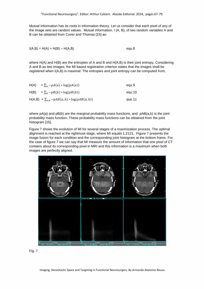
Figure 7 shows the evolution of MI for several stages of a maximization process. The optimal
alignment is reached at the rightmost stage, where MI equals 1.2121. Figure 7 presents the
image fusion for each condition and the corresponding joint histogram at the bottom frame. For
the case of figure 7 we can say that MI measure the amount of information that one pixel of CT
contains about its corresponding pixel in MRI and this information is a maximum when both
images are perfectly aligned.
Fig. 7
“Functional Neurosurgery”. Editor: Arthur Cukiert. Alaúde Editorial. 2014, pages 67-79.
Imaging, Stereotactic Space and Targeting in Functional Neurosurgery. By Armando Alaminos Bouza
It is important to note that MI is not a monotonic function of the transformation from A to B, so
the maximization search is not linear. There is a global maximum for the optimal alignment but
many other local maximum could exist. For these type of optimization problems reaching the
global maximum is not guaranteed. Robust multimodal registration techniques should include
some way to jump outside local maximums, on the contrary the solution might be sub-optimal.
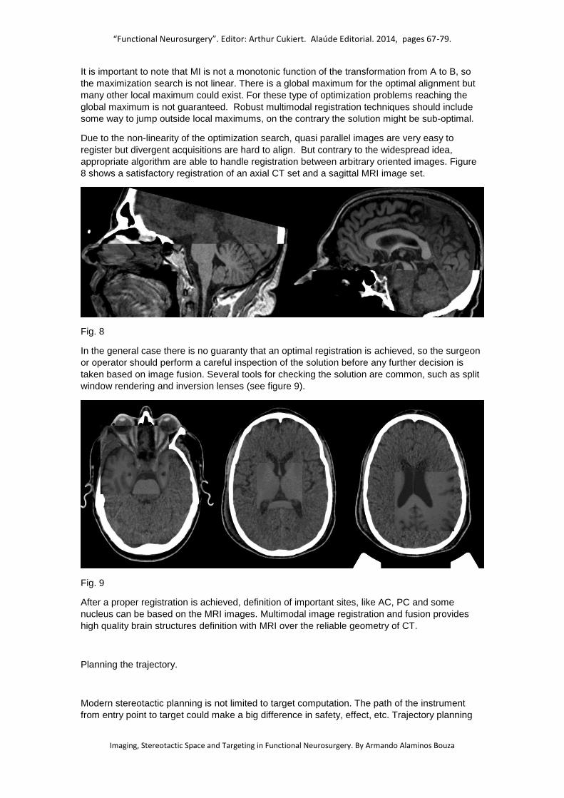
Due to the non-linearity of the optimization search, quasi parallel images are very easy to
register but divergent acquisitions are hard to align. But contrary to the widespread idea,
appropriate algorithm are able to handle registration between arbitrary oriented images. Figure
8 shows a satisfactory registration of an axial CT set and a sagittal MRI image set.
Fig. 8
In the general case there is no guaranty that an optimal registration is achieved, so the surgeon
or operator should perform a careful inspection of the solution before any further decision is
taken based on image fusion. Several tools for checking the solution are common, such as split
window rendering and inversion lenses (see figure 9).
Fig. 9
After a proper registration is achieved, definition of important sites, like AC, PC and some
nucleus can be based on the MRI images. Multimodal image registration and fusion provides
high quality brain structures definition with MRI over the reliable geometry of CT.
Planning the trajectory.
Modern stereotactic planning is not limited to target computation. The path of the instrument
from entry point to target could make a big difference in safety, effect, etc. Trajectory planning

“Functional Neurosurgery”. Editor: Arthur Cukiert. Alaúde Editorial. 2014, pages 67-79.
Imaging, Stereotactic Space and Targeting in Functional Neurosurgery. By Armando Alaminos Bouza
allows vascular accident prevention, reach two nucleus with a single electrode, avoid crossing
ventricular volume, etc. Most stereotactic planning systems provide tools for trajectory
simulation. Trajectories can be defined with a target and angles or with a target and its entry
point. Common tools includes 2D overlay of the instrument over anatomy and 3D projection
over anatomy and segmented structures, such as nucleus and ventricles. A special
representation called “probe view” is also useful. Figure 10 show a 3D representation of
electrodes with segmented ventricles and subthalamic nucleus (STn).
Fig. 10 – 3D representation of trajectory going to target inside STn. In this representation the
operator checks if the electrode is crossing ventricles.
Quality assurance and safety.
There is no way to ignore that stereotactic neurosurgery is a very complex process. Any
complex process is error prone and actions should be taken to keep error events at the lowest
possible frequency rate. Creating a routine check program could prevent lot of accidents. In this
paper we are constrained to targeting, but similar ideas could be extrapolated to other steps of
the surgical procedure.
Some safety checks recommended for implementation are:
Independent coordinates computation. Use some independent computation method, simple, such as manual or using an independent software. Check that the two set of coordinates are inside a tolerance radius. If the results are outside your tolerance, repeat your computations until the desired coincidence is reached.
Routine check of the proper calibration of your stereotactic apparatus and accessories. Stereotactic frames and aiming devices are sensitive to mechanical stress. Any minimal permanent deformation of your stereotactic system may produce systematic deviation from your planned target. Some devices have phantoms to perform test cases. If you do not have a phantom ask the manufacturer of your apparatus regarding instructions for this check and repeat it as regular procedure.
Intraoperative X-ray check of your target. Several instruments, as electrodes, are not rigid and any lateral mechanical tension is able to shift the tip of the instrument far from your planned target. To check and correct this effect make intraoperative X-ray and check that your instrument goes to the planned isocenter of the apparatus. See example in figure 11. If necessary, ask the manufacturer how to do that.

“Functional Neurosurgery”. Editor: Arthur Cukiert. Alaúde Editorial. 2014, pages 67-79.
Imaging, Stereotactic Space and Targeting in Functional Neurosurgery. By Armando Alaminos Bouza
Double-check of coordinate setting in the stereotactic apparatus. Ask other member of your surgical team to check, independently, the values of the coordinates on the device scales.
Other quality assurance actions are not mentioned here, because the chapter is focused on
imaging and targeting, but the author recommend a comprehensive revision and
implementation of all available safety measurements, such as stimulation, micro-recording, etc.
Fig. 11. Example of intraoperative X-ray check, showing electrode tip at the center of the
stereotactic system.
Conclusion
Stereotactic neurosurgery was a pioneer discipline in the use of medical imaging as guidance.
Stereotaxis still is one of the most technologically dependent surgical modalities. Surgeons
involved in stereotactic procedures should keep in touch with developments in diagnostic
imaging, image guided surgery, registration methods and several other technological subjects.
This chapter tried to bring into the community some details at the very core of the supporting
techniques.
References
1. Sturm V, Pastyr O, Schlegel W, et al. “Stereotactic computer tomography with a modified Riechert-Mundinger device as the basis for integrated stereotactic neuroradiological investigations”. Acta Neurochir (Wien) (1983) 68:11–17.
2. Zamorano L., Kadi M., Jiang Z, Diaz F. “Zamorano-Dujovny multipurpose neurosurgical image-guided localizing unit: experience in 866 consecutive cases of open stereotaxis". Stereotact. Funct. Neurosurg. (1994); 63 (1-4): 45-51.
3. Talairach, J.; David, M.; Tournoux, P. Kvasina, T. (1957). “Atlas D'AnatomieStereotaxique :RéperageRadiologique Indirect des Noyaux Gris Centraux des RègionsMesencephalo-sousoptique et Hypothalamique” L'Homme,Masson &Cie, Paris.
4. Schaltenbrand, G., Bailey, P. (1959). “Introduction to Stereotaxis with an atlas of the human brain” Thieme, Stuttgart.
5. Schaltenbrand, G., Wahren, W. (1977). “Atlas for Stereotaxy of the Human Brain with an accompanying guide”, Thieme, Stuttgart.
6. Morel Anne. (2007). “Stereotactic atlas of the human thalamus and basal ganglia”. Informa Healthcare USA, Inc.

“Functional Neurosurgery”. Editor: Arthur Cukiert. Alaúde Editorial. 2014, pages 67-79.
Imaging, Stereotactic Space and Targeting in Functional Neurosurgery. By Armando Alaminos Bouza
7. Alho L. E, Grinberg L, Heinsen H, Fonoff E. T. (2011). “Review of Printed and Electronic Stereotactic Atlases of the Human Brain”. Neuroimaging for Clinicians - Combining Research and Practice, Edited by Dr. Julio F. P. Peres, Publisher InTech .
8. Alaminos A., Ortega I., Molina H., et al. (1995). “A stereotactic surgical planning system for the IBM 386/486 PC Family". Stereotact. Funct. Neurosurg. 63 (1-4) 35.
9. Alaminos A. “MNPS – Mevis Neurosurgery Planning System. User Manual”. www.mevis.com.br
10. Niemann K., Naujokat Ch., Pohl G., Wollner C., Keyserlingk D. “Verification of the Schaltenbrand and Wahren stereotactic atlas”. Acta Neurochir (Wien) 1994 129:72-81.
11. Burchiel KL, Nguyen TT, Coombs BS, Szumoski J.”MRI distortion and stereotactic neurosurgery using the Cosman-Roberts-Wells and Leksell frames”. Stereotact Funct Neurosurg. 1996; 66(1-3): 123-36.
12. Yu Ch., Zbigniew P., Apuzzo ML. “An image fusion study of the geometric accuracy of magnetic resonance imaging with the Leksell stereotactic localization system”. Journal of Applied Clinical Medical Physics, vol 2, No. 1, 2001.
13. Viola P., Wells WM. “Alignment by Maximization of Mutual Information”. International Journal of Computer Vision, (1997) 24(2) 137-154.
14. Maes F., Collignon A., Vandermeulen D., Marchal G., Suetens P. “Multimodality image registration by maximization of Mutual Information”. IEEE Transactions of Medical Imaging, vol.16, no.2, 1997.
15. Cover, T. M. and Thomas, J.A., 1991, Elements of Information Theory, New York: John Wiley & Sons.
View publication statsView publication stats
Related Documents