Imaging Polymer Morphology Using Atomic Force Microscopy Russell J. Composto Materials Science and Engineering, and the Laboratory for Research on the Structure of Matter, University of Pennsylvania Agilent Web Seminar October 24th, 2007

Welcome message from author
This document is posted to help you gain knowledge. Please leave a comment to let me know what you think about it! Share it to your friends and learn new things together.
Transcript
Imaging Polymer Morphology Using AtomicForce Microscopy
Russell J. CompostoMaterials Science and Engineering, and
the Laboratory for Research on the Structure of Matter,University of Pennsylvania
Agilent Web SeminarOctober 24th, 2007

Case Studies:
1) Nanostructures assembled from amphiphilic block copolymer films.
2) Surface segregation of nanoparticles in homopolymer and blockcopolymers
0.25 µm × 0.25 µm
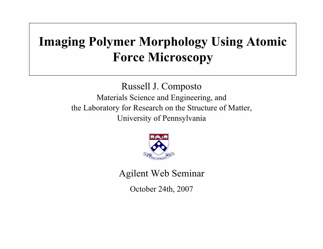
Amphiphilic Block CopolymerMaterials:Poly(styrene-b-tert-acrylic acid) (PS-b-PAA)
Procedure:• Spin-coat films from organic solvent• Anneal at 130 °C• Characterize:
Bulk: TGA and SAXS
Thin Film: FTIR-ATR, Ellipsometry, and AFM (aqueous, pH, solvent…)
PS-b-PtBA
fPAA = 0.19
Hydrophilic PAA cylinders in Hydrophobic PS matrix
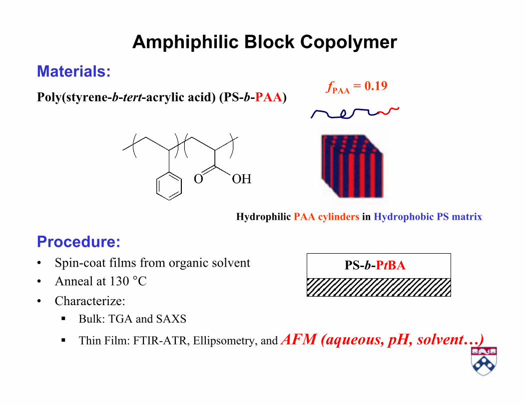
• AFM (PicoPlus, Agilent AFM)
(i) Magnetic AC (MAC) mode: intermittent contact mode
(ii) Silicon cantilever w/ magnetic coating: k = 2.8 N/m, tip radius < 7 nm,f (air) = 75 kHz, f (aqueous) = 30 kHz
(iii) Liquid cell
(iv) In situ scan for at least 2h: Capture swelling of soft nanostructure
• pH Buffer Solutions:
(i) Sodium Phosphate Buffers: H3PO4/NaH2PO4/Na2HPO4
(ii) pH range: 2.6 – 9.1
(iii) Buffer strength: 20 mM
In Situ AFM in Aqueous Environment
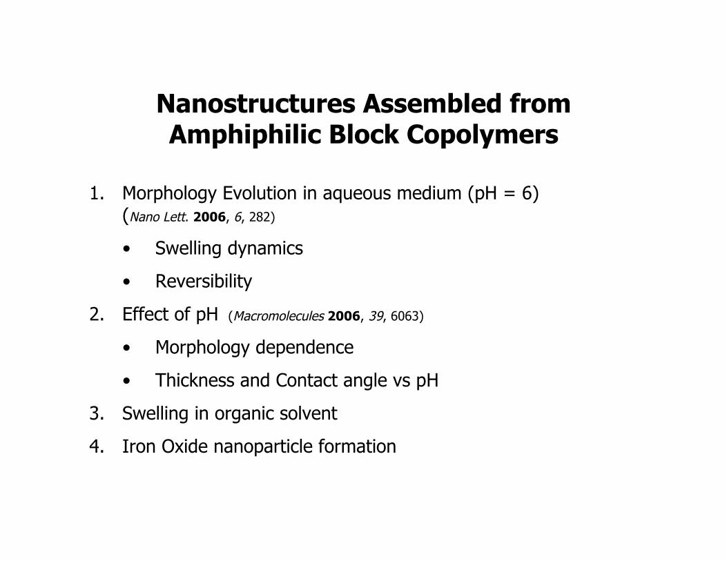
Nanostructures Assembled fromAmphiphilic Block Copolymers
1. Morphology Evolution in aqueous medium (pH = 6)(Nano Lett. 2006, 6, 282)
• Swelling dynamics
• Reversibility
2. Effect of pH (Macromolecules 2006, 39, 6063)
• Morphology dependence
• Thickness and Contact angle vs pH
3. Swelling in organic solvent
4. Iron Oxide nanoparticle formation

Nanostructured PS-b-PAA films (33 nm)
1 µm
0
20 nm
PS PAA
• Nearly hexagonal packing of cylinders,consistent with SAXS of bulk.
• Cylinder diameter: 23.7 ± 2.7 nm.
• Cylinder-to-cylinder spacing: 52.0 nm.
Grain Analysis (SPIP):
Nano Lett. 2006, 6, 282
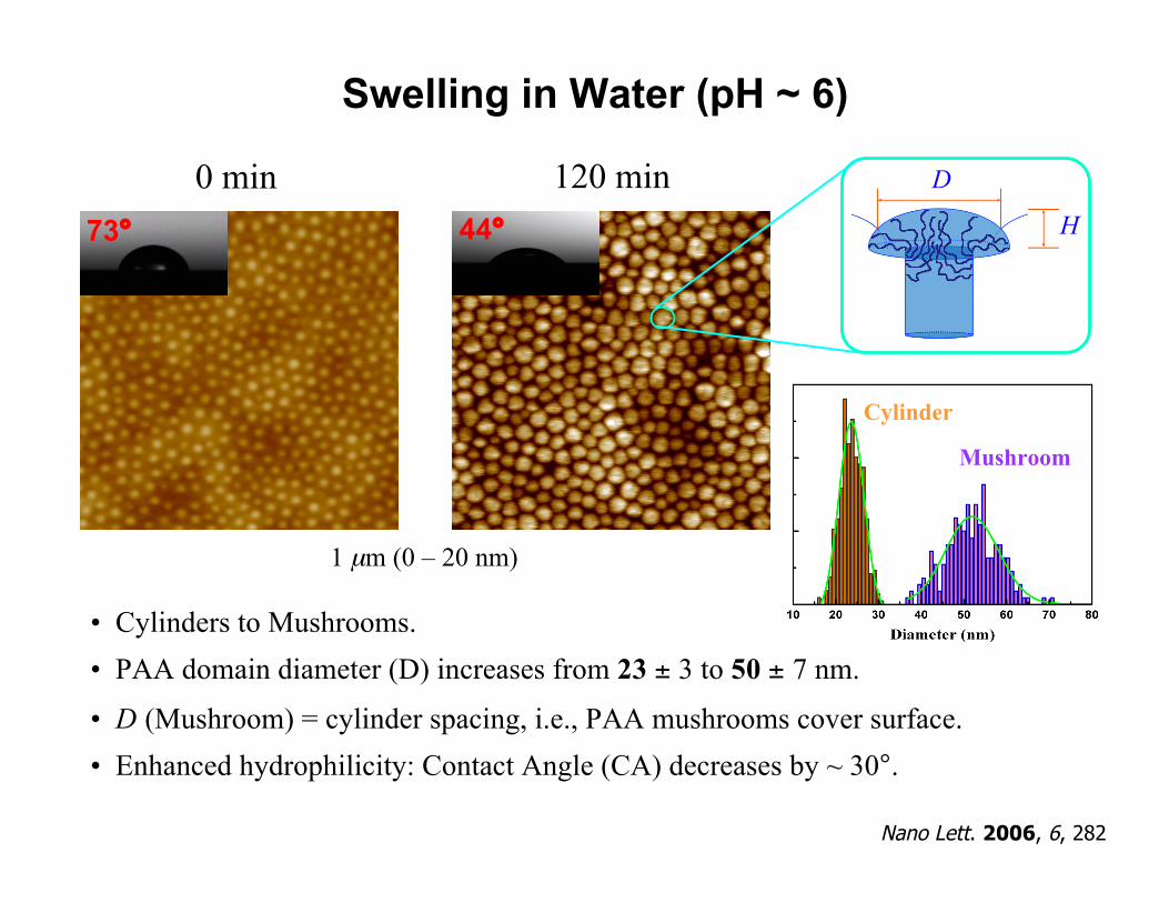
Swelling in Water (pH ~ 6)
0 min 120 minH
D
1 µm (0 – 20 nm)
73° 44°
Cylinder
Mushroom
• Cylinders to Mushrooms.• PAA domain diameter (D) increases from 23 ± 3 to 50 ± 7 nm.
• D (Mushroom) = cylinder spacing, i.e., PAA mushrooms cover surface.• Enhanced hydrophilicity: Contact Angle (CA) decreases by ~ 30°.
Nano Lett. 2006, 6, 282
1 µm (0 – 20 nm)
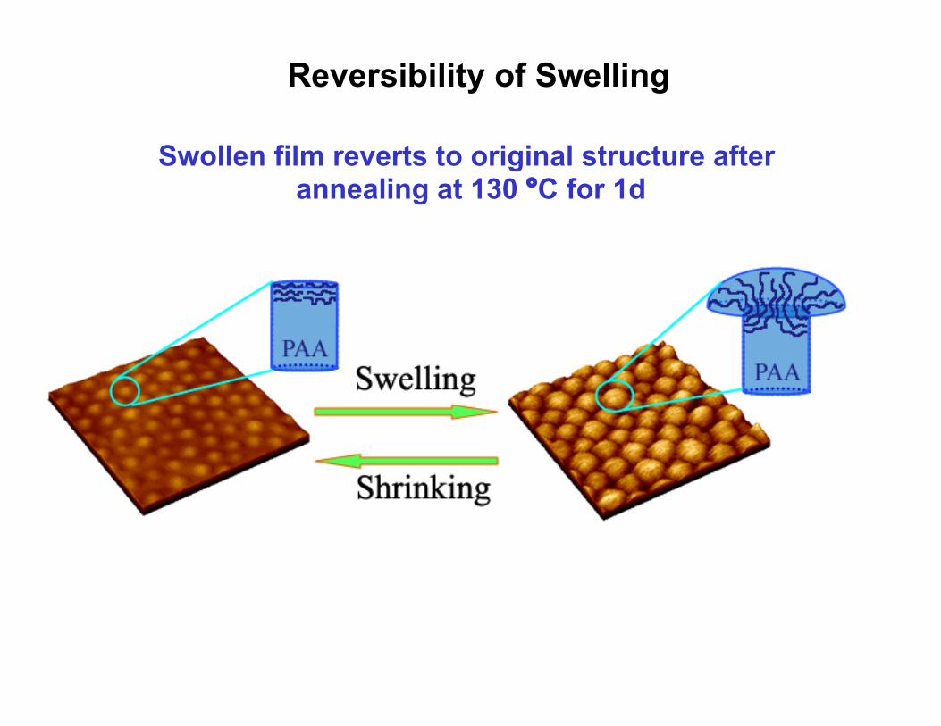
Reversibility of Swelling
Swollen film reverts to original structure after annealing at 130 °C for 1d
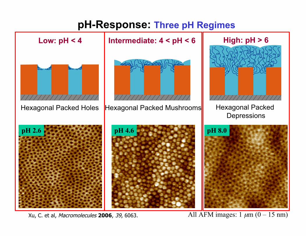
pH-Response: Three pH Regimes
pH 2.6
Xu, C. et al, Macromolecules 2006, 39, 6063. All AFM images: 1 µm (0 – 15 nm)
pH 4.6 pH 8.0
Low: pH < 4 High: pH > 6Intermediate: 4 < pH < 6
Hexagonal Packed Holes Hexagonal Packed Mushrooms Hexagonal Packed Depressions
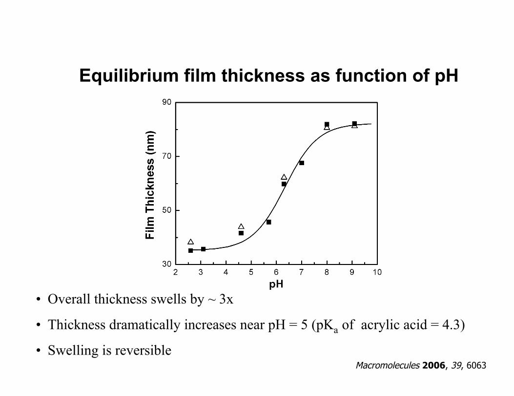
Equilibrium film thickness as function of pH
• Overall thickness swells by ~ 3x
• Thickness dramatically increases near pH = 5 (pKa of acrylic acid = 4.3)
• Swelling is reversibleMacromolecules 2006, 39, 6063
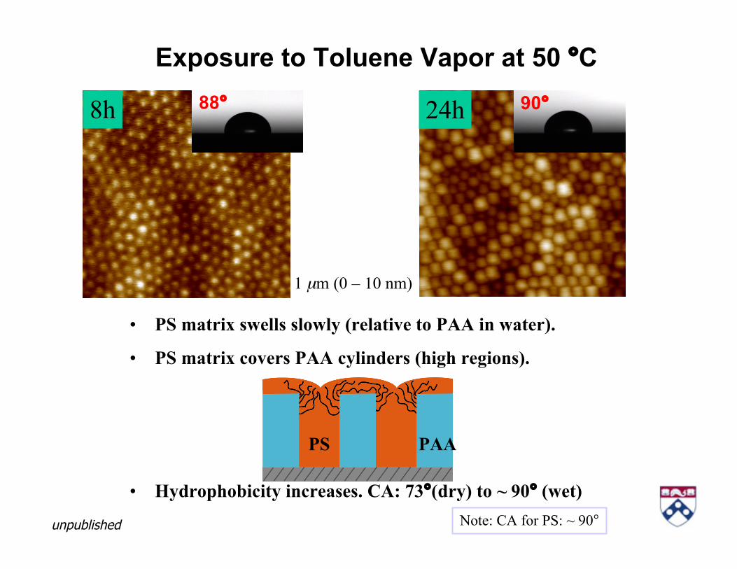
Exposure to Toluene Vapor at 50 °C
8h 24h
1 µm (0 – 10 nm)
88° 90°
• PS matrix swells slowly (relative to PAA in water).
• PS matrix covers PAA cylinders (high regions).
• Hydrophobicity increases. CA: 73°(dry) to ~ 90° (wet)Note: CA for PS: ~ 90°
PS PAA
unpublished
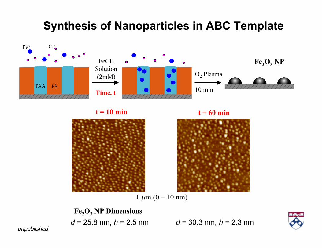
Synthesis of Nanoparticles in ABC Template
FeCl3Solution(2mM) O2 Plasma
10 min
Fe2O3 NP
Time, t
t = 10 min t = 60 min
1 µm (0 – 10 nm)
d = 25.8 nm, h = 2.5 nm d = 30.3 nm, h = 2.3 nmFe2O3 NP Dimensions
unpublished

Preparation of Ag NP in PMMA
O
O
Ag
CF3
CF3
HAg(CH3COO) +
C
CHO
CF3
O
H
CF3
CH3COOH +
MIBK
Ag(hfac)HhfacAg complex
Rubira, et al. Chem. Mater. (1994)
(185oC)Organic
AgNP
Ag(HFA)
PMMA 550 nm

Ag Nanoparticles (NP) in PMMA Films5 wt% Ag-PMMA 10 wt% Ag-PMMA 20 wt% Ag-PMMA
SPHERICAL FACETED
Height
Phase
500
nm
Deshmukh & RJC, Chem. Mater. (2007)

NP formation vs self-assembly of BCP?
L = lamella period
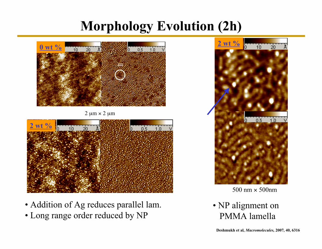
2 µm × 2 µm
0 wt %
• Addition of Ag reduces parallel lam. • Long range order reduced by NP
2 wt %
• NP alignment on PMMA lamella
500 nm × 500nm
2 wt %
Morphology Evolution (2h)
=
Deshmukh et al, Macromolecules, 2007, 40, 6316

Morphology Evolution (48 h)0 wt %
2 µm × 2 µm
=⊥
• domain growth ofparallel lamella “align”⊥ lamellae=
2 wt %
• NP slow down growthof parallel grains
• NP rejected fromparallel lamella
=
⊥
=
⊥
Deshmukh et al, Macromolecules, 2007, 40, 6316

96 h2 h
2 µm x 2 µm
• Stabilize perpendicular morphology (short range).
• Arrange NP’s into linear arrays along PMMA stripes.
c d
0.25 µm × 0.25 µm
5 wt %
Effect of Ag Concentration
Macromolecules, 2007, 40, 6316
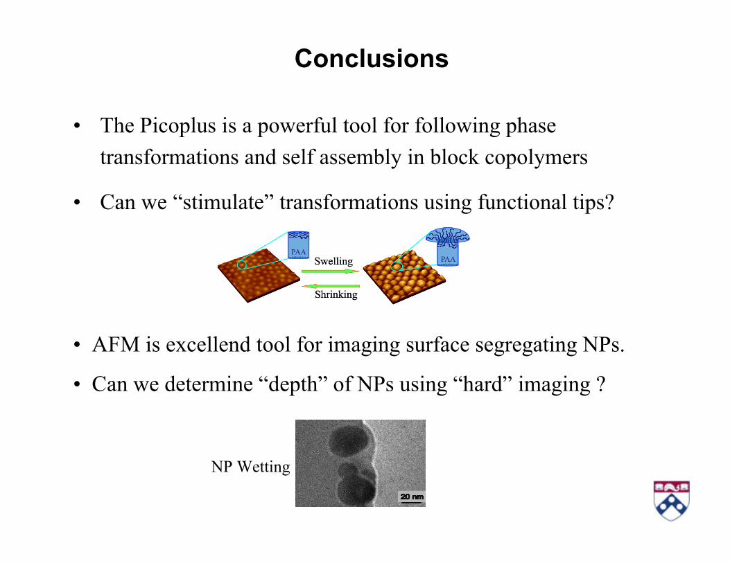
Conclusions
• The Picoplus is a powerful tool for following phasetransformations and self assembly in block copolymers
• Can we “stimulate” transformations using functional tips?
• AFM is excellend tool for imaging surface segregating NPs.
• Can we determine “depth” of NPs using “hard” imaging ?
NP Wetting
Contributions / AcknowledgementsGroup Members•Chen Xu, PhD Candidate in Materials Science
•Ranjan Deshmukh, PhD August 2007.
•Jay Park, PhD Candidate in Materials Science
Collaborators•Brad Wayland, Mike Fryd (Chemistry, Penn)
•Karen Winey (MSE, Penn)
•Song Xu (Agilent)
Acknowledgements:• National Science Foundation: DMR, MRSEC and NBIC programs.
• ACS- Petroleum Research Foundation.
• National Institute of Health (biomaterials)
• Nanotechnology Institute (biomaterials)
• Colgate-Palmolive Company (biomaterials)
• Agilent (instrumentation)
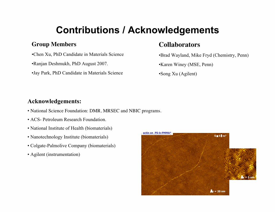
actin on PS-b-PMMA*5 × 5 ì m2
Äz = 20 nm
1 × 1 ì m2
Äz = 5 nm
Related Documents