IMAGE COMPRESSION USING DISCRETE COSINE TRANSFORM & DISCRETE WAVELET TRANSFORM A THESIS SUBMI TTED IN PARTIAL FULF ILLMENT OF THE REQUIREMENTS FOR THE DEGREE OF Bachelor in Technology In Computer Science and Engineering Submitted by Bhawna Gautam Roll no 10606053 Under the guidance of Prof R.Baliarsingh ABSTRACT It is used spec ia ll y for th e co mpre ssion of images wh ere tolera bl e degradation is required. With the wide use of computers and consequently need for large scale storage and transmission of data, efficient ways of storin g of data have become necess ary. With the growth of tech nolog y and entrance into the Digital Age, the world has found itself amid a vast amount of information. Dealing with such enormous information can often present difficulties. Image compression is minimizing the size in bytes of a graphics file without degrading the quality of the image to an unacceptable level. The reduction in file size allows more images to be stored in a given amount of disk or memory space. It also reduces the time required for images to be sent

Welcome message from author
This document is posted to help you gain knowledge. Please leave a comment to let me know what you think about it! Share it to your friends and learn new things together.
Transcript

8/7/2019 IMAGE Comp Dwt &Dct Ext
http://slidepdf.com/reader/full/image-comp-dwt-dct-ext 1/20
IMAGE COMPRESSION USING DISCRETE COSINE TRANSFORM
& DISCRETE WAVELET TRANSFORM
A THESIS SUBMITTED IN PARTIAL FULFILLMENT OF THE
REQUIREMENTS FOR THE DEGREE OF
Bachelor in Technology
In Computer Science and Engineering
Submitted by
Bhawna Gautam
Roll no 10606053
Under the guidance of
Prof R.Baliarsingh
ABSTRACT
It is used specially for the compression of images where tolerable
degradation is required. With the wide use of computers and consequently
need for large scale storage and transmission of data, efficient ways of
storing of data have become necessary. With the growth of technology and
entrance into the Digital Age, the world has found itself amid a vast amount
of information. Dealing with such enormous information can often present
difficulties. Image compression is minimizing the size in bytes of a graphics
file without degrading the quality of the image to an unacceptable level. The
reduction in file size allows more images to be stored in a given amount of
disk or memory space. It also reduces the time required for images to be sent
8/7/2019 IMAGE Comp Dwt &Dct Ext
http://slidepdf.com/reader/full/image-comp-dwt-dct-ext 2/20
over the Internet or downloaded from Web pages. JPEG and JPEG 2000 are
two important techniques used for image compression.
JPEG image compression standard use DCT (DISCRETE COSINE
TRANSFORM). The discrete cosine transform is a fast transform. It is a
widely used and robust method for image compression. It has excellent
compaction for highly correlated data. DCT has fixed basis images DCT
gives good compromise between information packing ability and
computational complexity.
JPEG 2000 image compression standard makes use of DWT (DISCRETE
WAVELET TRANSFORM). DWT can be used to reduce the image size
without losing much of the resolutions computed and values less than a pre-
specified threshold are discarded. Thus it reduces the amount of memory
required to represent given image.
Chapter 1
Introduction
Image compression is very important for efficient transmission and storage
of images. Demand for communication of multimedia data through the
telecommunications network and accessing the multimedia data through
Internet is growing explosively [14].With the use of digital cameras,
requirements for storage, manipulation, and transfer of digital images, has
grown explosively. These image files can be very large and can occupy a lot
of memory. A gray scale image that is 256 x 256 pixels have 65, 536
elements to store and a typical 640 x 480 color image have nearly a million.
Downloading of these files from internet can be very time consuming task.

8/7/2019 IMAGE Comp Dwt &Dct Ext
http://slidepdf.com/reader/full/image-comp-dwt-dct-ext 3/20
Image data comprise of a significant portion of the multimedia data and they
occupy the major portion of the communication bandwidth for multimedia
communication. Therefore development of efficient techniques for image
compression has become quite necessary [9]. A common characteristic of
most images is that the neighboring pixels are highly correlated and
therefore contain highly redundant information. The basic objective of
image compression is to find an image representation in which pixels are
less correlated. The two fundamental principles used in image compression
are redundancy and irrelevancy. Redundancy removes redundancy from the
signal source and irrelevancy omits pixel values which are not noticeable by
human eye. JPEG and JPEG 2000 are two important techniques used for
image compression.
Work on international standards for image compression started in the late
1970s with the CCITT (currently ITU-T) need to standardize binary image
compression algorithms for Group 3 facsimile communications. Since then,
many other committees and standards have been formed to produce dejure
standards (such as JPEG), while several commercially successful initiatives
have effectively become de facto standards (such as GIF). Image
compression standards bring about many benefits, such as: (1) easier
exchange of image files between different devices and applications; (2)
reuse of existing hardware and software for a wider array of products; (3)
existence of benchmarks and reference data sets for new and alternative
developments.
8/7/2019 IMAGE Comp Dwt &Dct Ext
http://slidepdf.com/reader/full/image-comp-dwt-dct-ext 4/20
Chapter 2
Image Compression
2.1 Need for image compression:
The need for image compression becomes apparent when number of bits per
image is computed resulting from typical sampling rates and quantization
methods. For example, the amount of storage required for given images is (i)
a low resolution, TV quality, color video image which has 512 x 512
pixels/color,8 bits/pixel, and 3 colors approximately consists of 6 x 10⁶ bits;
(ii) a 24 x 36 mm negative photograph scanned at 12 x 10⁻⁶mm:3000 x
2000 pixels/color, 8 bits/pixel, and 3 colors nearly contains 144 x 10⁶ bits;(3) a 14 x 17 inch radiograph scanned at 70 x 10⁻⁶mm: 5000 x 6000
pixels,12 bits/pixel nearly contains 360 x 10⁶ bits. Thus storage of even a
few images could cause a problem. As another example of the need for
image compression, consider the transmission of low resolution 512 x 512 x
8 bits/pixel x 3-color video image over telephone lines. Using a 96000 bauds
(bits/sec) modem, the transmission would take approximately 11 minutes for
just a single image, which is unacceptable for most applications.
2.2 Principles behind compression:
Number of bits required to represent the information in an image can be
minimized by removing the redundancy present in it. There are three types
of redundancies: (i) spatial redundancy, which is due to the correlation or
dependence between neighboring pixel values; (ii) spectral redundancy,
which is due to the correlation between different color planes or spectral
bands; (iii) temporal redundancy, which is present because of correlation
between different frames in images. Image compression research aims to
8/7/2019 IMAGE Comp Dwt &Dct Ext
http://slidepdf.com/reader/full/image-comp-dwt-dct-ext 5/20
reduce the number of bits required to represent an image by removing the
spatial and spectral redundancies as much as possible.
Data redundancy is of central issue in digital image compression. If n1 and
n2 denote the number of information carrying units in original and
compressed image respectively, then the compression ratio CR can be
defined as
CR=n1/n2;
And relative data redundancy RD of the original image can be defined as
RD=1-1/CR;
Three possibilities arise here:
(1) If n1=n2, then CR=1 and hence RD=0 which implies that original image
do not contain any redundancy between the pixels.
(2) If n1>>n1, then CR→∞ and hence RD>1 which implies considerable
amount of redundancy in the original image.
(3) If n1<<n2, then CR>0 and hence RD→-∞ which indicates that thecompressed image contains more data than original image.
2.3 Types of compression:
Lossless versus Lossy compression: In lossless compression schemes, the
reconstructed image, after compression, is numerically identical to the
original image. However lossless compression can only a achieve a modest
amount of compression. Lossless compression is preferred for archival
purposes and often medical imaging, technical drawings, clip art or comics.
This is because lossy compression methods, especially when used at low bit
rates, introduce compression artifacts. An image reconstructed following
lossy compression contains degradation relative to the original. Often this is

8/7/2019 IMAGE Comp Dwt &Dct Ext
http://slidepdf.com/reader/full/image-comp-dwt-dct-ext 6/20
because the compression scheme completely discards redundant
information. However, lossy schemes are capable of achieving much higher
compression. Lossy methods are especially suitable for natural images such
as photos in applications where minor (sometimes imperceptible) loss of
fidelity is acceptable to achieve a substantial reduction in bit rate. The lossy
compression that produces imperceptible differences can be called visually
lossless.
Predictive versus Transform coding: In predictive coding, information
already sent or available is used to predict future values, and the difference
is coded. Since this is done in the image or spatial domain, it is relatively
simple to implement and is readily adapted to local image characteristics.
Differential Pulse Code Modulation (DPCM) is one particular example of
Predictive coding. Transform coding, on the other hand, first transforms the
image from its spatial domain representation to a different type of
representation using some well-known transform and then codes the
transformed values (coefficients). This method provides greater data
compression compared to predictive methods, although at the expense of
greater computational requirements.
Fig(2.1) Image Compression model
8/7/2019 IMAGE Comp Dwt &Dct Ext
http://slidepdf.com/reader/full/image-comp-dwt-dct-ext 7/20
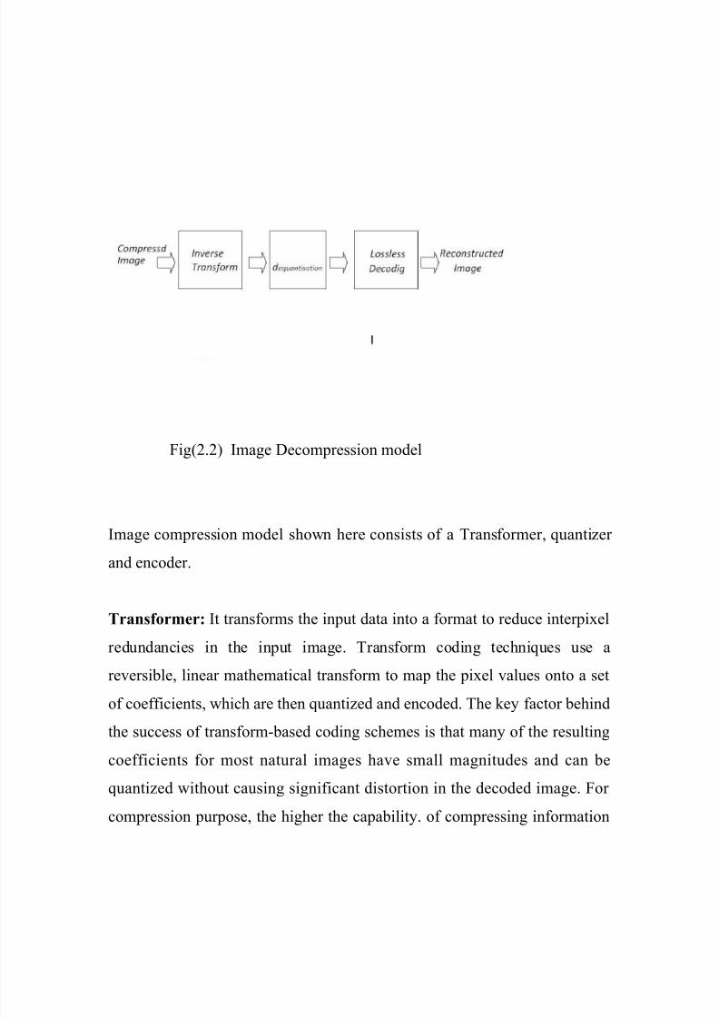
Fig(2.2) Image Decompression model
Image compression model shown here consists of a Transformer, quantizer
and encoder.
Transformer: It transforms the input data into a format to reduce interpixel
redundancies in the input image. Transform coding techniques use a
reversible, linear mathematical transform to map the pixel values onto a set
of coefficients, which are then quantized and encoded. The key factor behind
the success of transform-based coding schemes is that many of the resulting
coefficients for most natural images have small magnitudes and can be
quantized without causing significant distortion in the decoded image. For
compression purpose, the higher the capability. of compressing information
8/7/2019 IMAGE Comp Dwt &Dct Ext
http://slidepdf.com/reader/full/image-comp-dwt-dct-ext 8/20
in fewer coefficients, the better the transform; for that reason, the Discrete
Cosine Transform (DCT) and Discrete Wavelet Transform(DWT) have
become the most widely used transform coding techniques.
Transform coding algorithms usually start by partitioning the original image
into subimages (blocks) of small size (usually 8 × 8). For each block the
transform coefficients are calculated, effectively converting the original 8 ×
8 array of pixel values into an array of coefficients within which the
coefficients closer to the top-left corner usually contain most of the
information needed to quantize and encode (and eventually perform the
reverse process at the decoder’s side) the image with little perceptual
distortion. The resulting coefficients are then quantized and the output of the
quantizer is used by symbol encoding techniques to produce the output bit-
stream representing the encoded image. In image decompression model at
the decoder’s side, the reverse process takes place, with the obvious
difference that the dequantization stage will only generate an approximated
version of the original coefficient values e.g., whatever loss was introduced
by the quantizer in the encoder stage is not reversible.
Quantizer: It reduces the accuracy of the transformer’s output in
accordance with some pre-established fidelity criterion. Reduces the psycho
visual redundancies of the input image. This operation is not reversible and
must be omitted if lossless compression is desired. The quantization stage is
at the core of any lossy image encoding algorithm. Quantization at the
encoder side, means partitioning of the input data range into a smaller set of
values. There are two main types of quantizers: scalar quantizers and vector
quantizers. A scalar quantizer partitions the domain of input values into a
smaller number of intervals. If the output intervals are equally spaced, which
is the simplest way to do it, the process is called uniform scalar quantization;
8/7/2019 IMAGE Comp Dwt &Dct Ext
http://slidepdf.com/reader/full/image-comp-dwt-dct-ext 9/20
otherwise, for reasons usually related to minimization of total distortion, it is
called non uniform scalar quantization. One of the most popular non uniform
quantizers is the Lloyd- Max quantizer. Vector quantization (VQ) techniques
extend the basic principles of scalar quantization to multiple dimensions.
Symbol (entropy) encoder: It creates a fixed or variable-length code to
represent the quantizer’s output and maps the output in accordance with the
code. In most cases, a variable-length code is used. An entropy encoder
compresses the compressed values obtained by the quantizer to provide
more efficient compression. Most important types of entropy encoders used
in lossy image compression techniques are arithmetic encoder, Huffman
encoder and run-length encoder.
Chapter 4
Image Compression using Discrete Wavelet Transform
Wavelet Transform has become an important method for image
compression. Wavelet based coding provides substantial improvement in
picture quality at high compression ratios mainly due to better energy
compaction property of wavelet transforms.
Wavelet transform partitions a signal into a set of functions called wavelets.
Wavelets are obtained from a single prototype wavelet called mother
wavelet by dilations and shifting. The wavelet transform is computed
separately for different segments of the time-domain signal at different
frequencies.
4.1 Subband coding:
8/7/2019 IMAGE Comp Dwt &Dct Ext
http://slidepdf.com/reader/full/image-comp-dwt-dct-ext 10/20
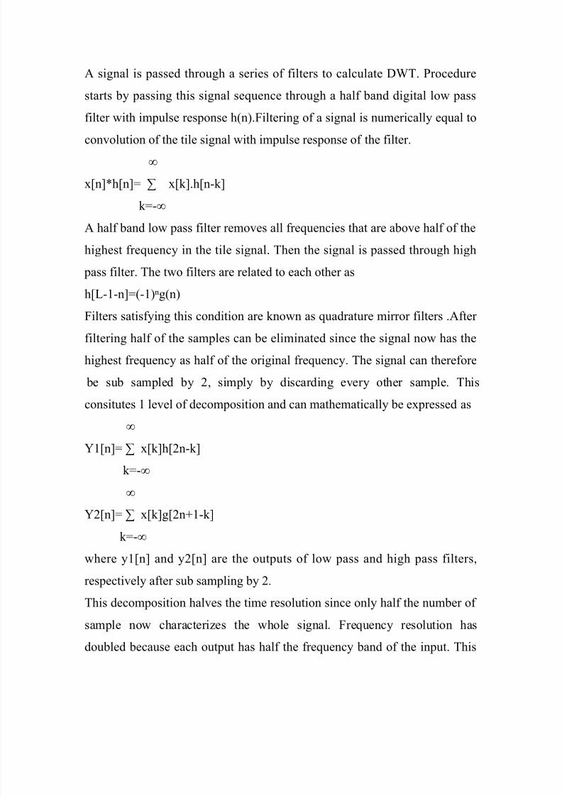
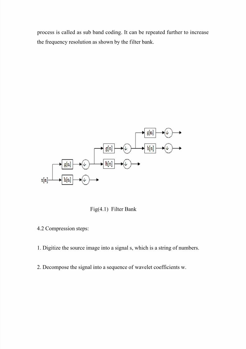
A signal is passed through a series of filters to calculate DWT. Procedure
starts by passing this signal sequence through a half band digital low pass
filter with impulse response h(n).Filtering of a signal is numerically equal to
convolution of the tile signal with impulse response of the filter.
∞
x[n]*h[n]= ∑ x[k].h[n-k]
k=-∞
A half band low pass filter removes all frequencies that are above half of the
highest frequency in the tile signal. Then the signal is passed through high
pass filter. The two filters are related to each other as
h[L-1-n]=(-1)ⁿg(n)
Filters satisfying this condition are known as quadrature mirror filters .After
filtering half of the samples can be eliminated since the signal now has the
highest frequency as half of the original frequency. The signal can therefore
be sub sampled by 2, simply by discarding every other sample. This
consitutes 1 level of decomposition and can mathematically be expressed as
∞
Y1[n]= ∑ x[k]h[2n-k]
k=-∞
∞
Y2[n]= ∑ x[k]g[2n+1-k]
k=-∞
where y1[n] and y2[n] are the outputs of low pass and high pass filters,
respectively after sub sampling by 2.
This decomposition halves the time resolution since only half the number of
sample now characterizes the whole signal. Frequency resolution has
doubled because each output has half the frequency band of the input. This
8/7/2019 IMAGE Comp Dwt &Dct Ext
http://slidepdf.com/reader/full/image-comp-dwt-dct-ext 11/20
process is called as sub band coding. It can be repeated further to increase
the frequency resolution as shown by the filter bank.
Fig(4.1) Filter Bank
4.2 Compression steps:
1. Digitize the source image into a signal s, which is a string of numbers.
2. Decompose the signal into a sequence of wavelet coefficients w.
8/7/2019 IMAGE Comp Dwt &Dct Ext
http://slidepdf.com/reader/full/image-comp-dwt-dct-ext 12/20
3. Use threshold to modify the wavelet coefficients from w to w’.
4. Use quantization to convert w’ to a sequence q.
5. Entropy encoding is applied to convert q into a sequence e.
Digitation
The image is digitized first. The digitized image can be characterized by its
intensity levels, or scales of gray which range from 0(black) to 255(white),
and its resolution, or how many pixels per square inch.Thresholding
In certain signals, many of the wavelet coefficients are close or equal to
zero. Through threshold these coefficients are modified so that the sequence
of wavelet coefficients contains long strings of zeros.
In hard threshold, a threshold is selected. Any wavelet whose absolute value
falls below the tolerance is set to zero with the goal to introduce many zeros
without losing a great amount of detail.
Quantization
Quantization converts a sequence of floating numbers w’ to a sequence of
integers q. The simplest form is to round to the nearest integer. Another
method is to multiply each number in w’ by a constant k, and then round to
the nearest integer. Quantization is called lossy because it introduces error
into the process, since the conversion of w’ to q is not one to one function.
Entropy encoding
With this method, a integer sequence q is changed into a shorter sequence e,
with the numbers in e being 8 bit integers. The conversion is made by an
8/7/2019 IMAGE Comp Dwt &Dct Ext
http://slidepdf.com/reader/full/image-comp-dwt-dct-ext 13/20
entropy encoding table. Strings of zeros are coded by numbers 1 through
100,105 and 106, while the non-zero integers in q are coded by 101 through
104 and 107 through 254.
4.3 DWT Results:
.
8/7/2019 IMAGE Comp Dwt &Dct Ext
http://slidepdf.com/reader/full/image-comp-dwt-dct-ext 14/20
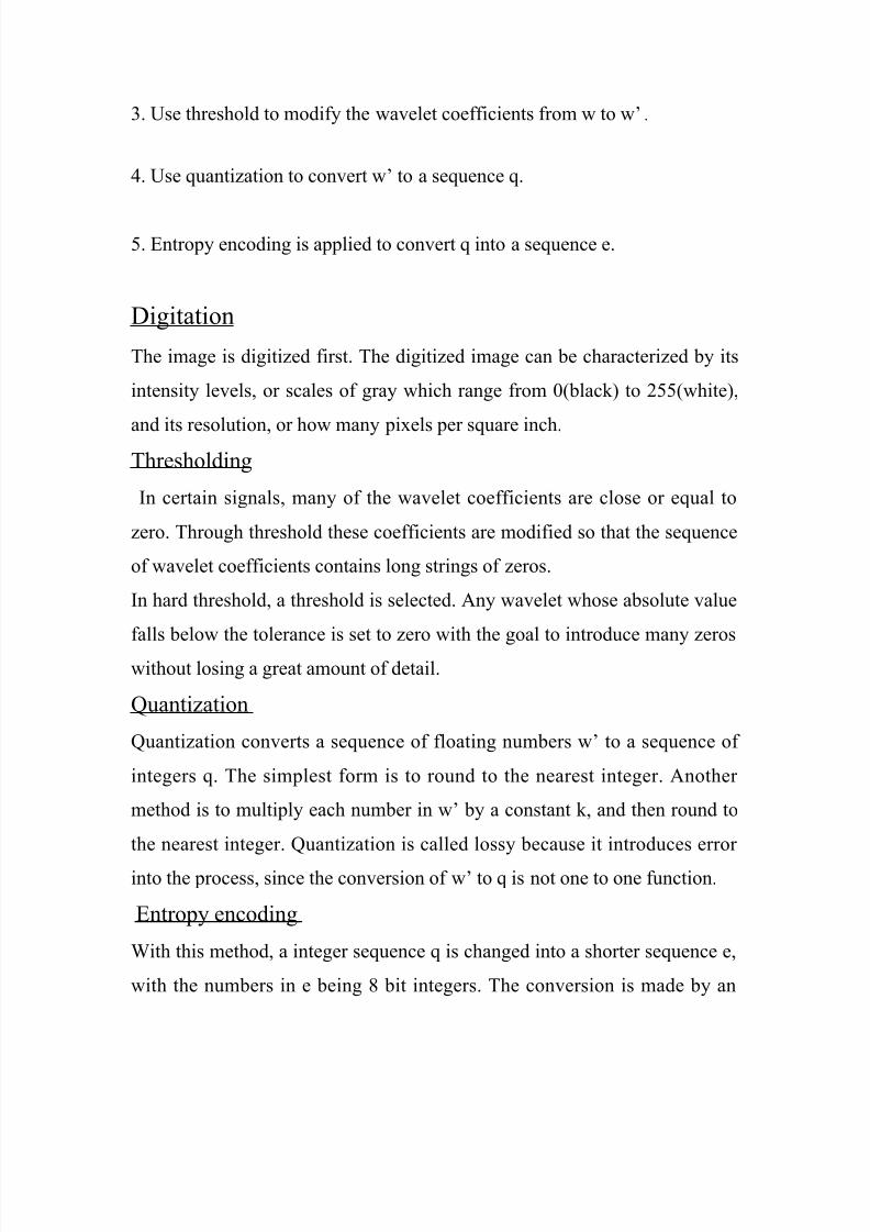
Fig (4.3.1) Original Lena imag
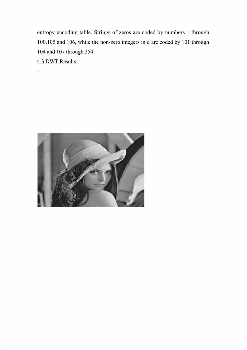
Fig (4.3.2) Compressed Image for threshold value 1

8/7/2019 IMAGE Comp Dwt &Dct Ext
http://slidepdf.com/reader/full/image-comp-dwt-dct-ext 15/20
Fig 4.3.3) Compressed Image for threshold value 2
Fig (4.3.4) Compressed Image for threshold value 5
8/7/2019 IMAGE Comp Dwt &Dct Ext
http://slidepdf.com/reader/full/image-comp-dwt-dct-ext 16/20
4.4 Results for DWT based on various performance parameters :
Mean Squared Error (MSE) is defined as the square of differences in the
pixel values between the corresponding pixels of the two images. Graph
DWT based image compression Fig (4.4.1) shows that MSE first decreases
with increase in window size and then starts to increase slowly with finally
attaining a constant value. Fig(4.4.2) plot show required for compressing
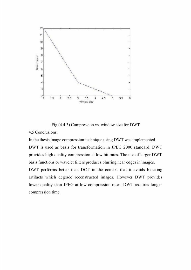
image with change in window size for DWT. Fig (4.4.3) indicate
compression ratio with change in window size for DWT based image
compression techniques. Compression decreases with increase in window
size for DWT.

8/7/2019 IMAGE Comp Dwt &Dct Ext
http://slidepdf.com/reader/full/image-comp-dwt-dct-ext 17/20
Fig(4.4.1) Mean Squared Error vs. window size for DWT

8/7/2019 IMAGE Comp Dwt &Dct Ext
http://slidepdf.com/reader/full/image-comp-dwt-dct-ext 18/20
Fig(4.4.2) Utilization vs window size for DWT
8/7/2019 IMAGE Comp Dwt &Dct Ext
http://slidepdf.com/reader/full/image-comp-dwt-dct-ext 19/20
Fig (4.4.3) Compression vs. window size for DWT
4.5 Conclusions:
In the thesis image compression technique using DWT was implemented.DWT is used as basis for transformation in JPEG 2000 standard. DWT
provides high quality compression at low bit rates. The use of larger DWT
basis functions or wavelet filters produces blurring near edges in images.
DWT performs better than DCT in the context that it avoids blocking
artifacts which degrade reconstructed images. However DWT provides
lower quality than JPEG at low compression rates. DWT requires longer
compression time.

8/7/2019 IMAGE Comp Dwt &Dct Ext
http://slidepdf.com/reader/full/image-comp-dwt-dct-ext 20/20
Related Documents


![A Comparative study of Digital Watermarking algorithms DWT ... · (DCT), Discrete Wavelet Transform (DWT) and Singular Value Decomposition (SVD)[2]. The rest of the paper is organized](https://static.cupdf.com/doc/110x72/5faec4be5f2aff6d172d895a/a-comparative-study-of-digital-watermarking-algorithms-dwt-dct-discrete-wavelet.jpg)