Modal Excitation D. L. Brown University of Cincinnati Structural Dynamics Research Laboratory M. A. Peres The Modal Shop, Inc Cincinnati, OH IMAC-XXVI, Modal Excitation, #356, Feb 04, 2008,

IMAC2008 Modal Excitation Tutorial RevF
Oct 12, 2014
Welcome message from author
This document is posted to help you gain knowledge. Please leave a comment to let me know what you think about it! Share it to your friends and learn new things together.
Transcript

Modal Excitation
D. L. BrownUniversity of Cincinnati
Structural Dynamics Research Laboratory
M. A. PeresThe Modal Shop, Inc
Cincinnati, OH
IMAC-XXVI, Modal Excitation, #356, Feb 04, 2008,
IMAC-XXVI -- Modal Excitation
2
Intoduction
• The presentation is concerned with a short tutorial on modal excitation. It will cover:– Types of Methods
• Force Appropriation Methods (Normal Mode)• Frequency Response Methods
– Excitation Signals Types– Exciters
• Impactors• Hydraulic and Electro-mechanical
– Measurement and Signal Processing Considerations
IMAC-XXVI -- Modal Excitation
3
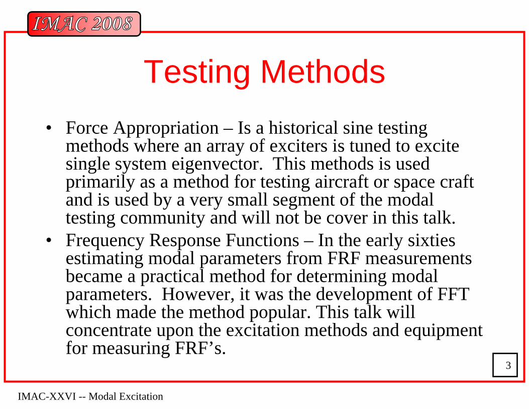
Testing Methods • Force Appropriation – Is a historical sine testing
methods where an array of exciters is tuned to excite single system eigenvector. This methods is used primarily as a method for testing aircraft or space craft and is used by a very small segment of the modal testing community and will not be cover in this talk.
• Frequency Response Functions – In the early sixties estimating modal parameters from FRF measurements became a practical method for determining modal parameters. However, it was the development of FFT which made the method popular. This talk will concentrate upon the excitation methods and equipment for measuring FRF’s.
IMAC-XXVI -- Modal Excitation
4
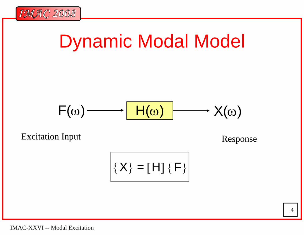
Dynamic Modal Model
H(ω)F(ω) X(ω)
{X} = [H] {F}
Excitation Input Response
IMAC-XXVI -- Modal Excitation
5
Excitation Signals• The type of excitation signal used to estimate
frequency response functions depends upon several factors. Generally, the excitation signal is chosen in order to minimize noise while estimating the most accurate frequency response function in the least amount of time. With the advent of the FFT, excitation signals are most often contain broadband frequency information and are limited by the requirements of the FFT (totally observed transients or periodic functions with respect to the observation window).
IMAC-XXVI -- Modal Excitation
6
Noise Reduction
• Types of noise:– Non-Coherent– Signal processing (Leakage)– Non-Linear
Noise is reduced by averaging in the non-coherent case, by signal processing and excitation type for the leakage case , and by randomizing and averaging for the non-linear case.
IMAC-XXVI -- Modal Excitation
7
Excitation Types
• Steady State– Slow Sine Sweep– Stepped Sine
• Random– True Random
• Periodic– Fast Sine Sweep
(Chirp)– Pseudo Random– Periodic Random
• Transient– Burst Random– Impact– Step Relaxation
• Operating
IMAC-XXVI -- Modal Excitation
8
Excitation Signal Characteristics
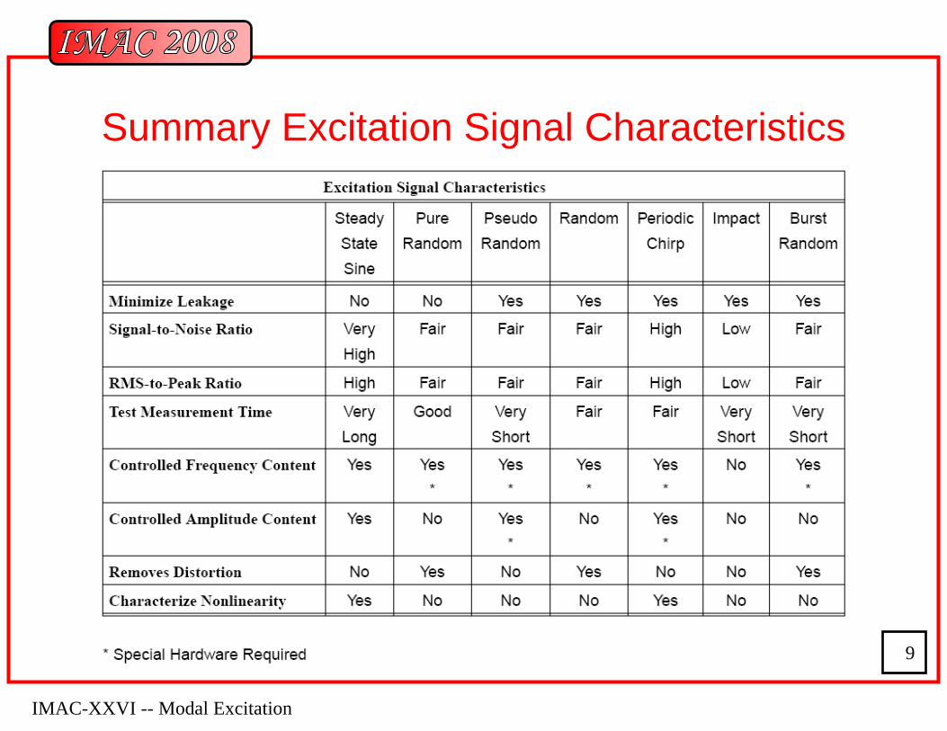
• RMS to Peak• Signal to Noise• Distortion• Test Time• Controlled Frequency Content• Controlled Amplitude Content• Removes Distortion Content• Characterizes Non Linearites
IMAC-XXVI -- Modal Excitation
9
Summary Excitation Signal Characteristics
IMAC-XXVI -- Modal Excitation
10
Modal Testing Set Up
• What’s the purpose of the test?• Application• Accuracy needs• Non-linearities• Testing time• Expected utilization of the data• Testing cost• Equipment availability
IMAC-XXVI -- Modal Excitation
11
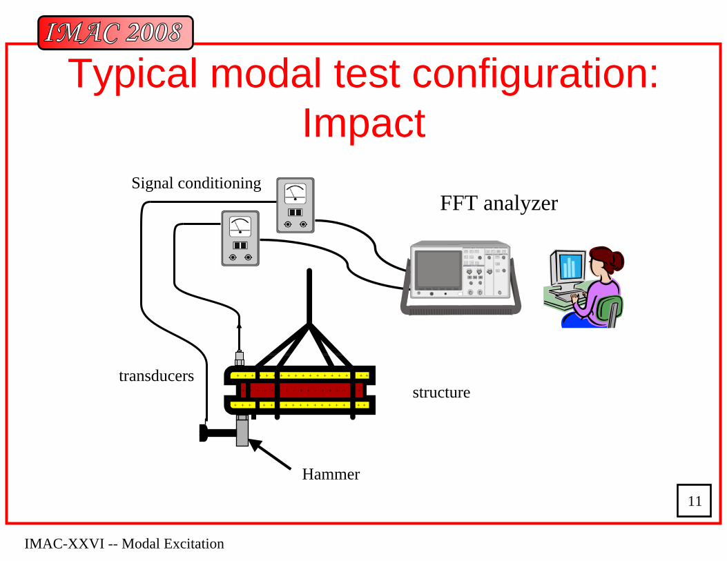
Typical modal test configuration: Impact
FFT analyzerSignal conditioning
structure+ + + + + + + + + + + + + + + + + + + +
+ + + + + + + + + + + + + + + + +
+ + + + + + + + + + + + + + + + + + + +
transducers
TRIGGER
DISPLAYDISPLAY
DISPLAY
HORIZONTAL
Hammer
IMAC-XXVI -- Modal Excitation
12
Input Spectrum• Factors controlling the frequency span of the input spectrum
– Stiffness of the impact tip– Compliance of the impacted surface– Mass of the impactor– Impact velocity
• The input spectrum should roll-off between 10 and 20 dB over the frequency range of interest– At least 10 dB so that modes above the frequency range of interest are
not excited– No more than 20 dB so that the modes in the frequency range of
interest are adequately excited
IMAC-XXVI -- Modal Excitation
13
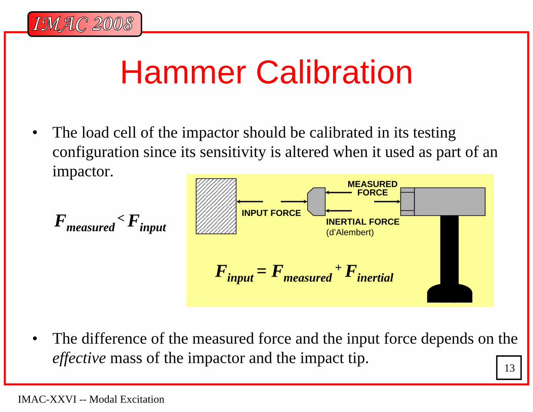
Hammer Calibration
MEASUREDFORCE
INERTIAL FORCE(d’Alembert)
INPUT FORCE
Finput = Fmeasured+ Finertial
Fmeasured< Finput
• The load cell of the impactor should be calibrated in its testing configuration since its sensitivity is altered when it used as part of an impactor.
• The difference of the measured force and the input force depends on the effective mass of the impactor and the impact tip.
MEASUREDFORCE
INERTIAL FORCE(d’Alembert)
INPUT FORCE
Finput = Fmeasured+ Finertial
MEASUREDFORCE
INERTIAL FORCE(d’Alembert)
INPUT FORCE
Finput = Fmeasured+ Finertial
MEASUREDFORCE
INERTIAL FORCE(d’Alembert)
INPUT FORCE
Finput = Fmeasured+ Finertial
IMAC-XXVI -- Modal Excitation
14
m
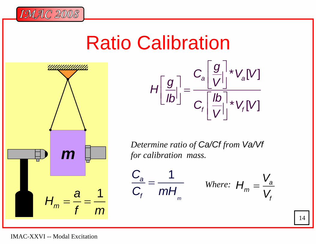
Ratio Calibration
1m
aHf m
= =
* [ ]
* [ ]
a a
f f
gC V Vg VH
lblb C V VV
⎡ ⎤⎢ ⎥⎡ ⎤ ⎣ ⎦=⎢ ⎥ ⎡ ⎤⎣ ⎦⎢ ⎥⎣ ⎦
1
m
a
f
CC mH
= Where:
Determine ratio of Ca/Cf from Va/Vffor calibration mass.
am
f
VHV
=

IMAC-XXVI -- Modal Excitation
15
Hammer Calibration Pictures
IMAC-XXVI -- Modal Excitation
16
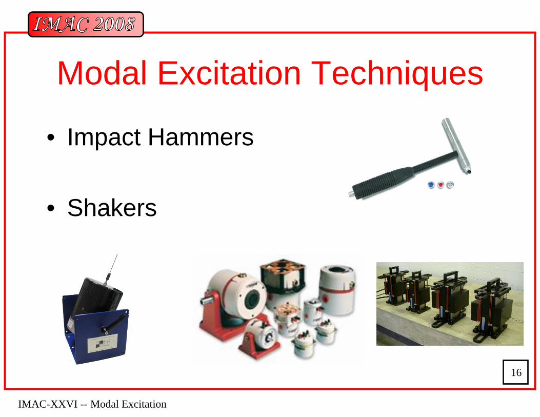
Modal Excitation Techniques
• Impact Hammers
• Shakers
IMAC-XXVI -- Modal Excitation
17
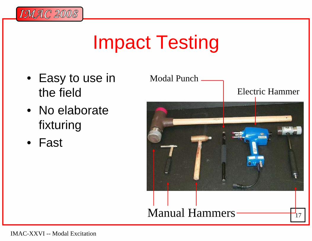
Impact Testing
• Easy to use in the field
• No elaborate fixturing
• Fast
Manual Hammers
Modal PunchElectric Hammer

IMAC-XXVI -- Modal Excitation
18
Impactors
IMAC-XXVI -- Modal Excitation
19
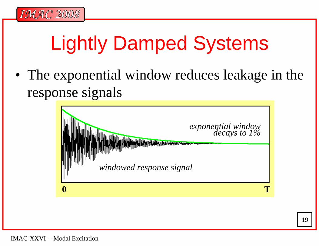
Lightly Damped Systems• The exponential window reduces leakage in the
response signals
0 T
unwindowed response signal
0 T
windowed response signal
exponential window decays to 1%
IMAC-XXVI -- Modal Excitation
20
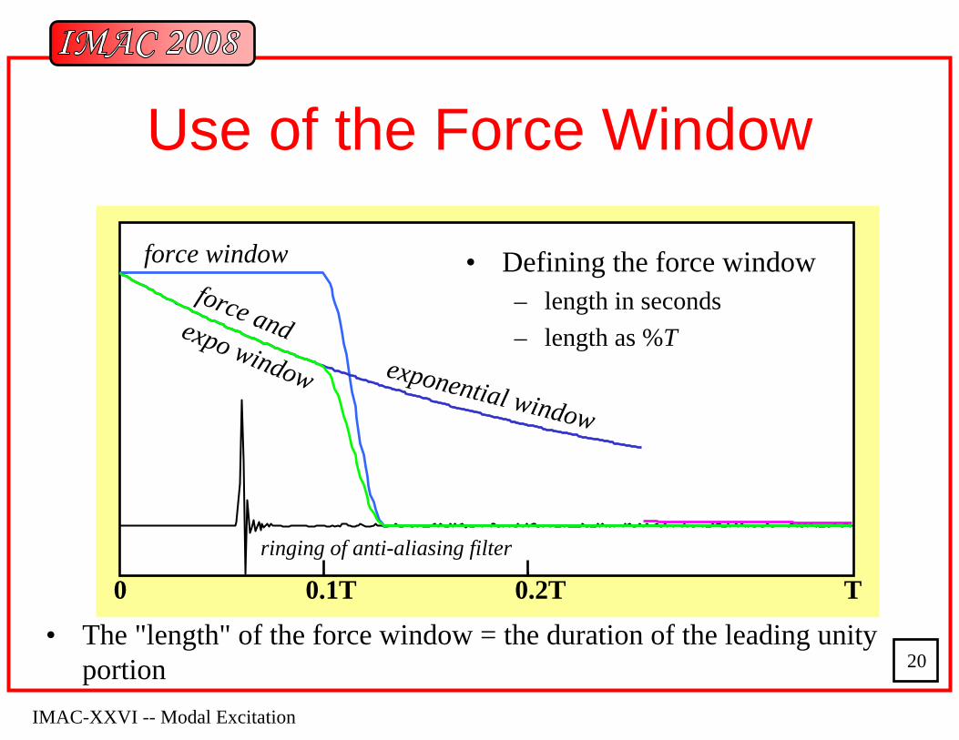
Use of the Force Window
• The "length" of the force window = the duration of the leading unity portion
0 T0.1T 0.2T
force window
exponential window
force andexpo window
ringing of anti-aliasing filter
• Defining the force window– length in seconds– length as %T
IMAC-XXVI -- Modal Excitation
21
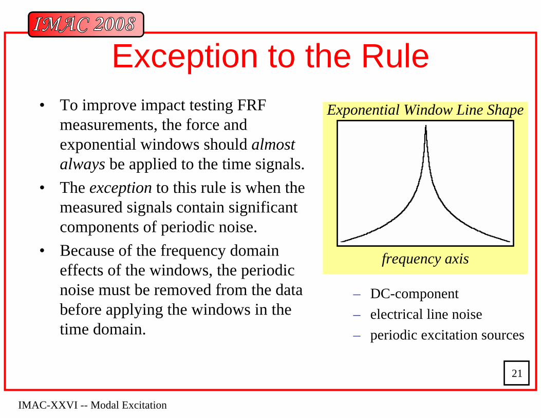
Exception to the Rule• To improve impact testing FRF
measurements, the force and exponential windows should almost always be applied to the time signals.
• The exception to this rule is when the measured signals contain significant components of periodic noise.
• Because of the frequency domain effects of the windows, the periodic noise must be removed from the data before applying the windows in the time domain.
– DC-component– electrical line noise– periodic excitation sources
frequency axis
Exponential Window Line Shape
IMAC-XXVI -- Modal Excitation
22
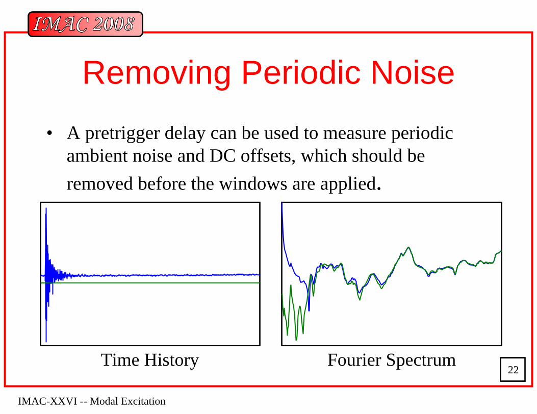
Removing Periodic Noise• A pretrigger delay can be used to measure periodic
ambient noise and DC offsets, which should be removed before the windows are applied.
Time History Fourier Spectrum
IMAC-XXVI -- Modal Excitation
23
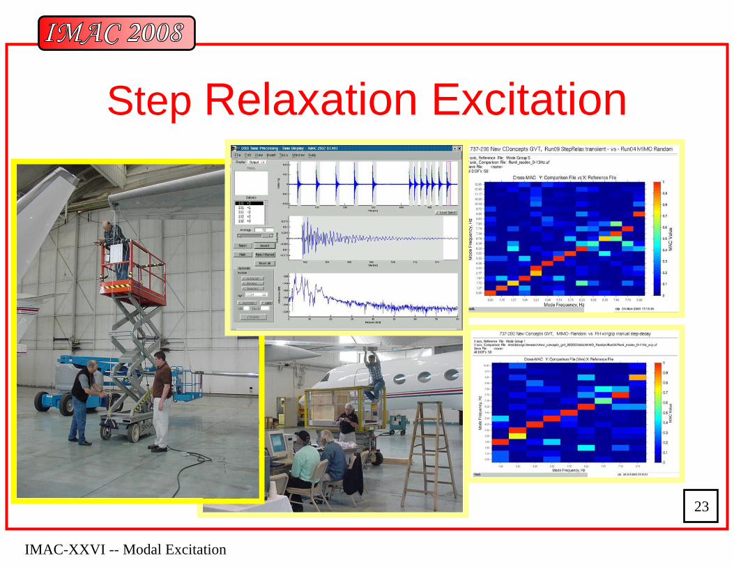
Step Relaxation Excitation
IMAC-XXVI -- Modal Excitation
24
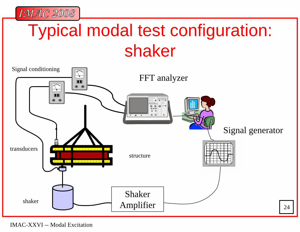
Typical modal test configuration: shaker
Shaker Amplifier
FFT analyzer
Signal generator
Signal conditioning
structure+ + + + + + + + + + + + + + + + + + + +
+ + + + + + + + + + + + + + + + +
+ + + + + + + + + + + + + + + + + + + +
shaker
transducers
TRIGGER
DISPLAYDISPLAY
DISPLAY
HORIZONTAL
IMAC-XXVI -- Modal Excitation
25
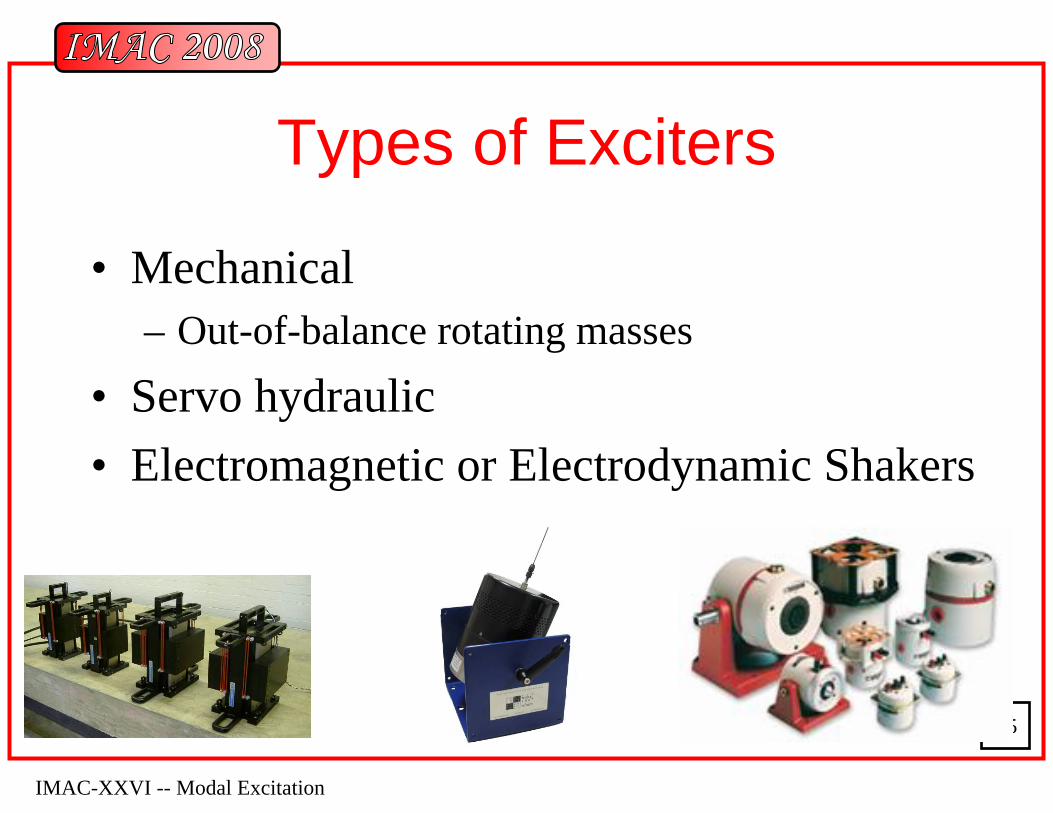
Types of Exciters
• Mechanical– Out-of-balance rotating masses
• Servo hydraulic• Electromagnetic or Electrodynamic Shakers
IMAC-XXVI -- Modal Excitation
26
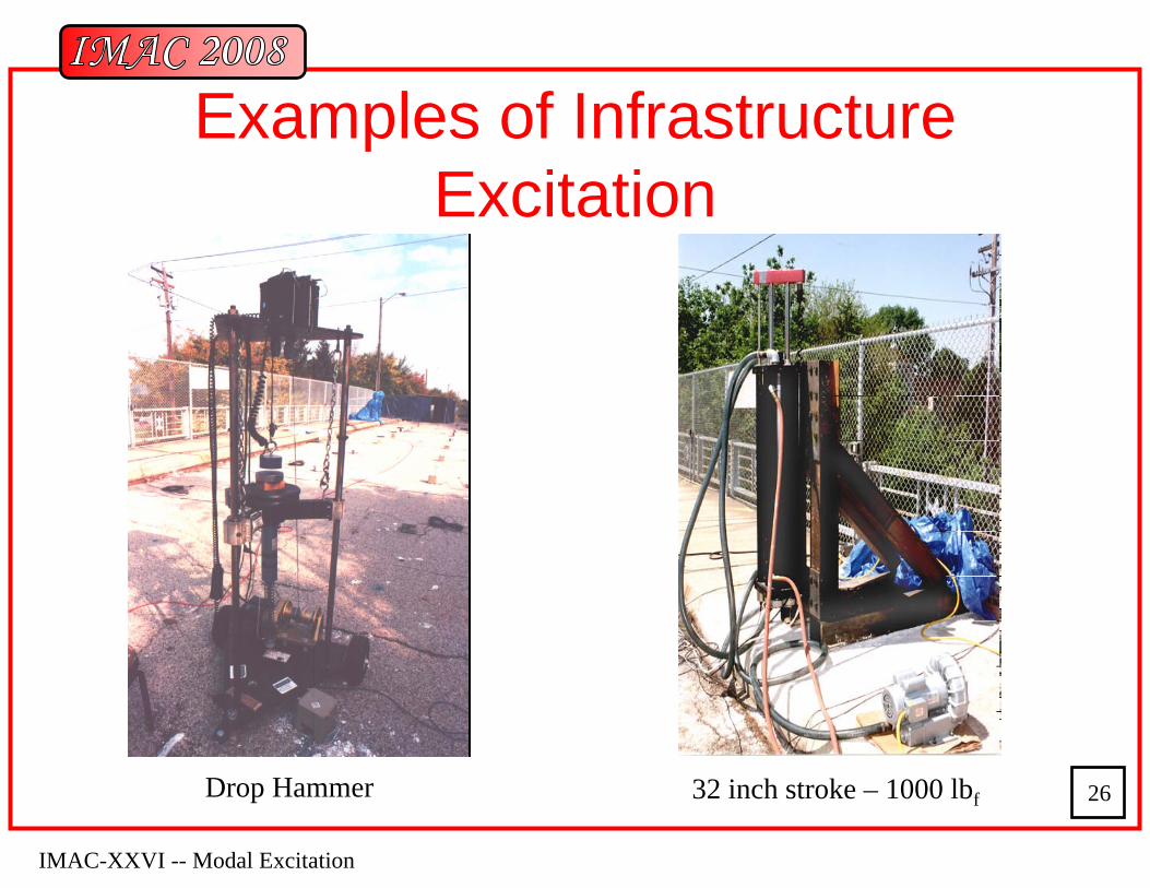
Examples of InfrastructureExcitation
Drop Hammer 32 inch stroke – 1000 lbf
IMAC-XXVI -- Modal Excitation
27
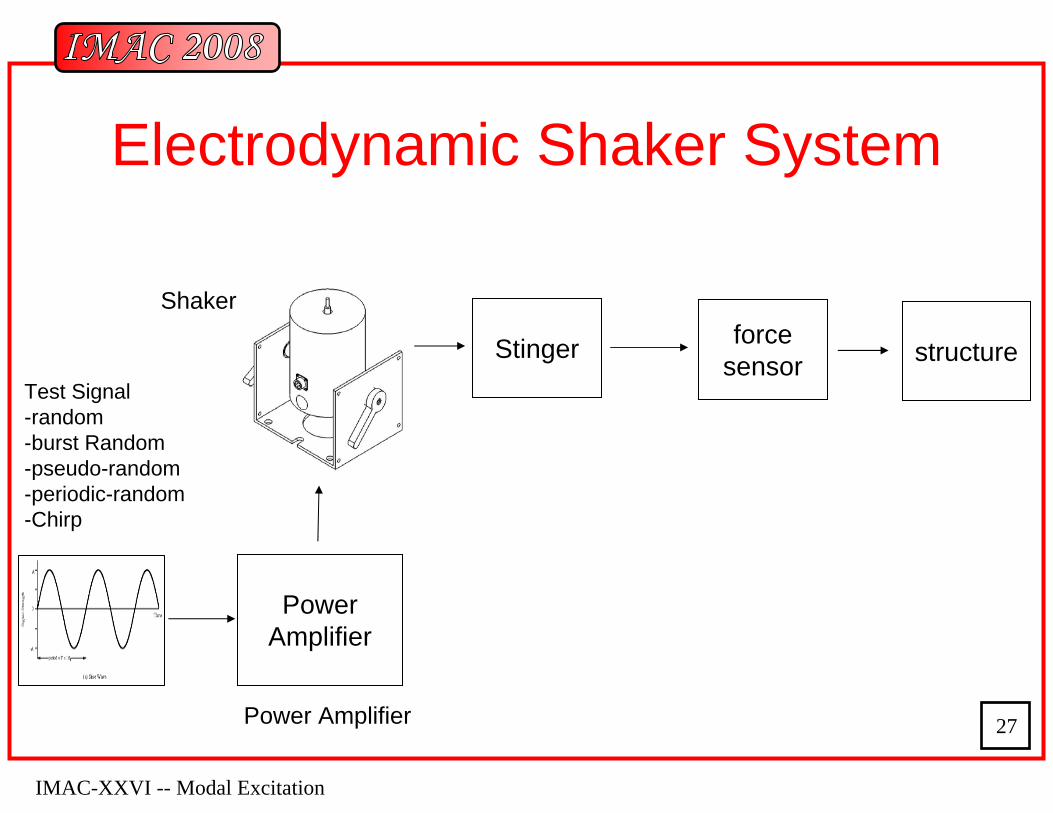
Test Signal-random-burst Random-pseudo-random-periodic-random-Chirp
Power Amplifier
Power Amplifier
Electrodynamic Shaker System
Stinger force sensor structure
Shaker
IMAC-XXVI -- Modal Excitation
28
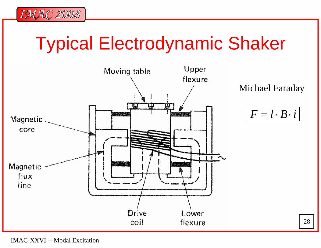
Typical Electrodynamic Shaker
Michael Faraday
iBlF ⋅⋅=
IMAC-XXVI -- Modal Excitation
29
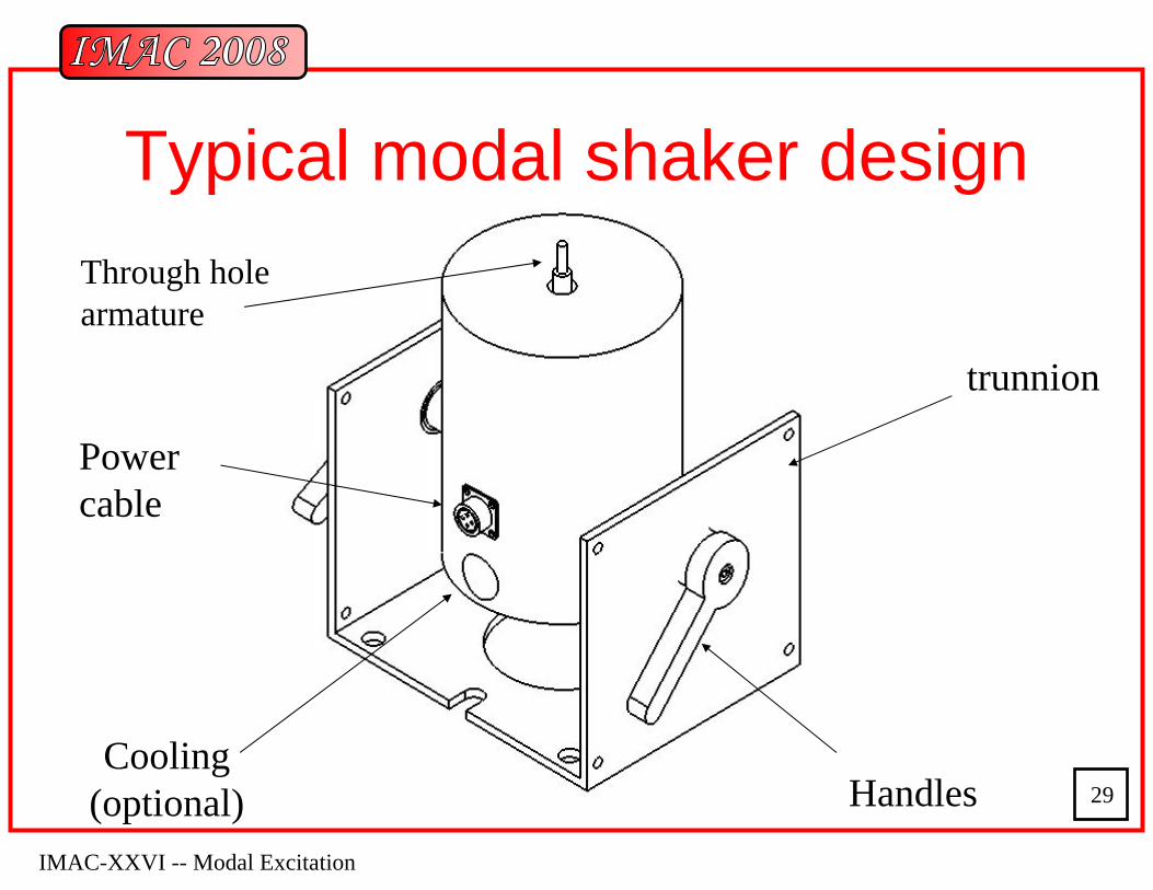
Typical modal shaker design
Cooling (optional) Handles
Power cable
trunnion
Through hole armature
IMAC-XXVI -- Modal Excitation
30
Important Shaker Considerations
• Excitation Point• Boundary Conditions• Fixturing
– Exciter support systems– Alignment– Attachment to the structure: stingers
IMAC-XXVI -- Modal Excitation
31
Excitation Points
• must be able to excite all modes of interest– node points of node lines
• not good points if you want to suppress all modes• Good points if you want to suppress modes you are
not interested on
• Pre-testing with impact hammer– Helps determine the best excitation point
• FEM (Finite Element Model)– Helps determine best excitation point
IMAC-XXVI -- Modal Excitation
32
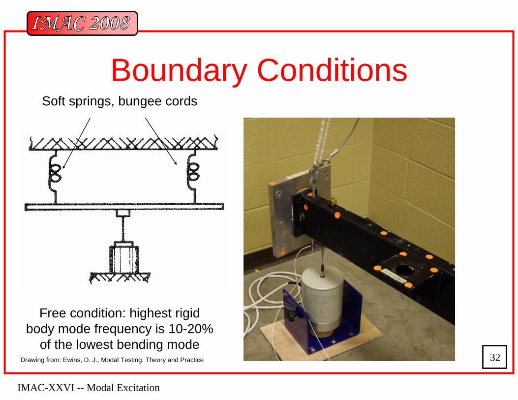
Boundary Conditions
Free condition: highest rigid body mode frequency is 10-20%
of the lowest bending mode
Soft springs, bungee cords
Drawing from: Ewins, D. J., Modal Testing: Theory and Practice
IMAC-XXVI -- Modal Excitation
33
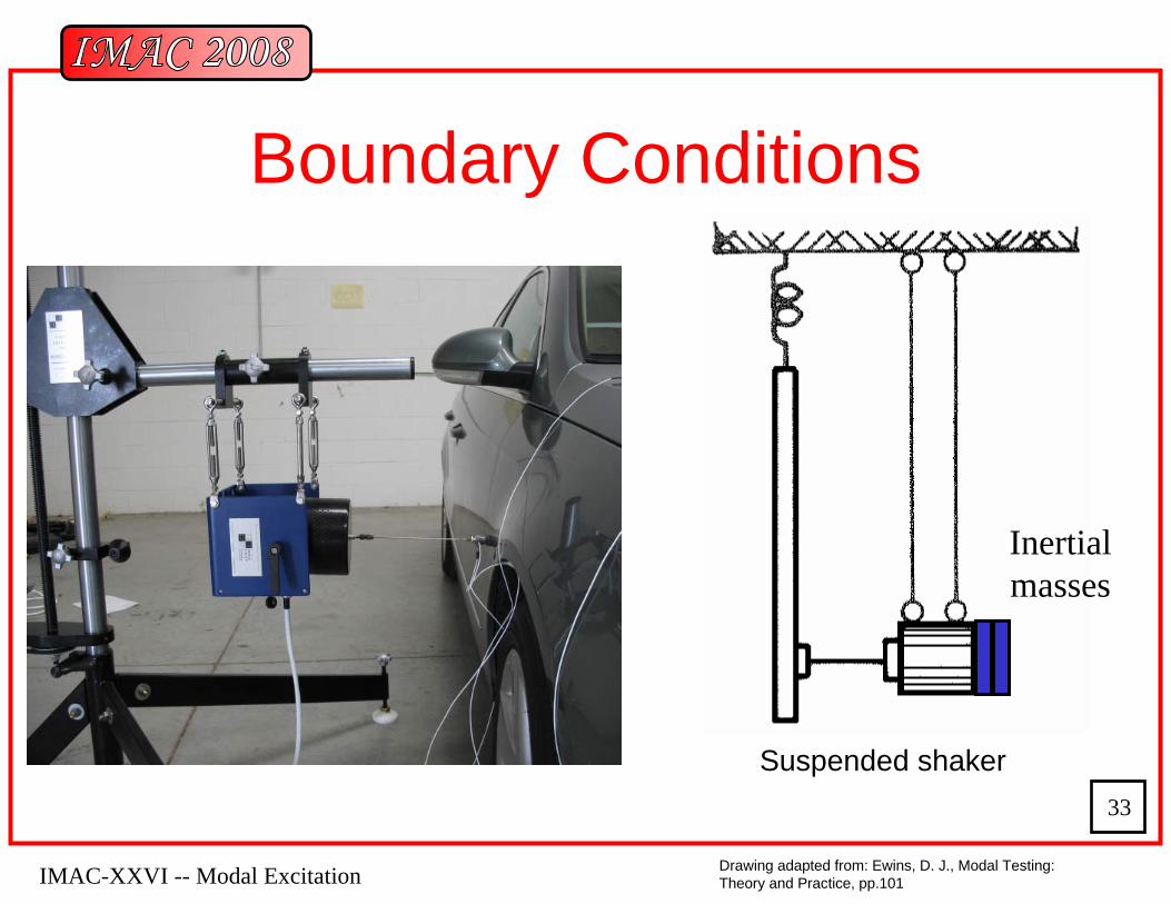
Boundary Conditions
Drawing adapted from: Ewins, D. J., Modal Testing: Theory and Practice, pp.101
Inertial masses
Suspended shaker
IMAC-XXVI -- Modal Excitation
34
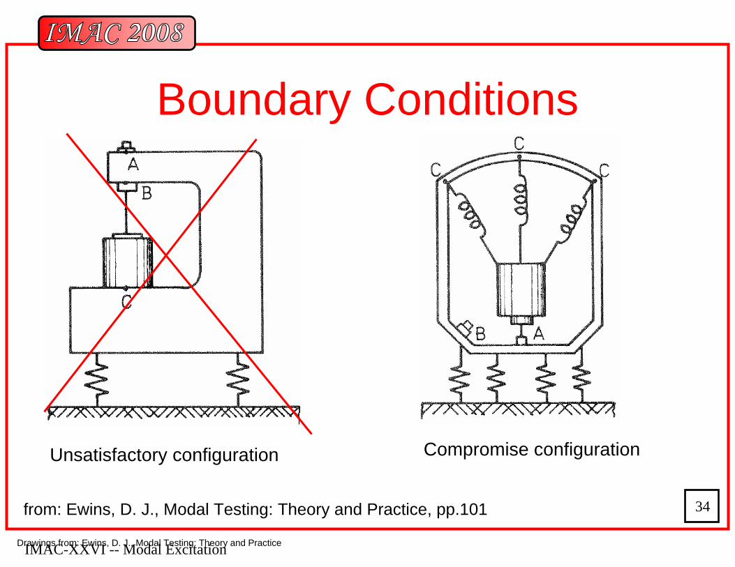
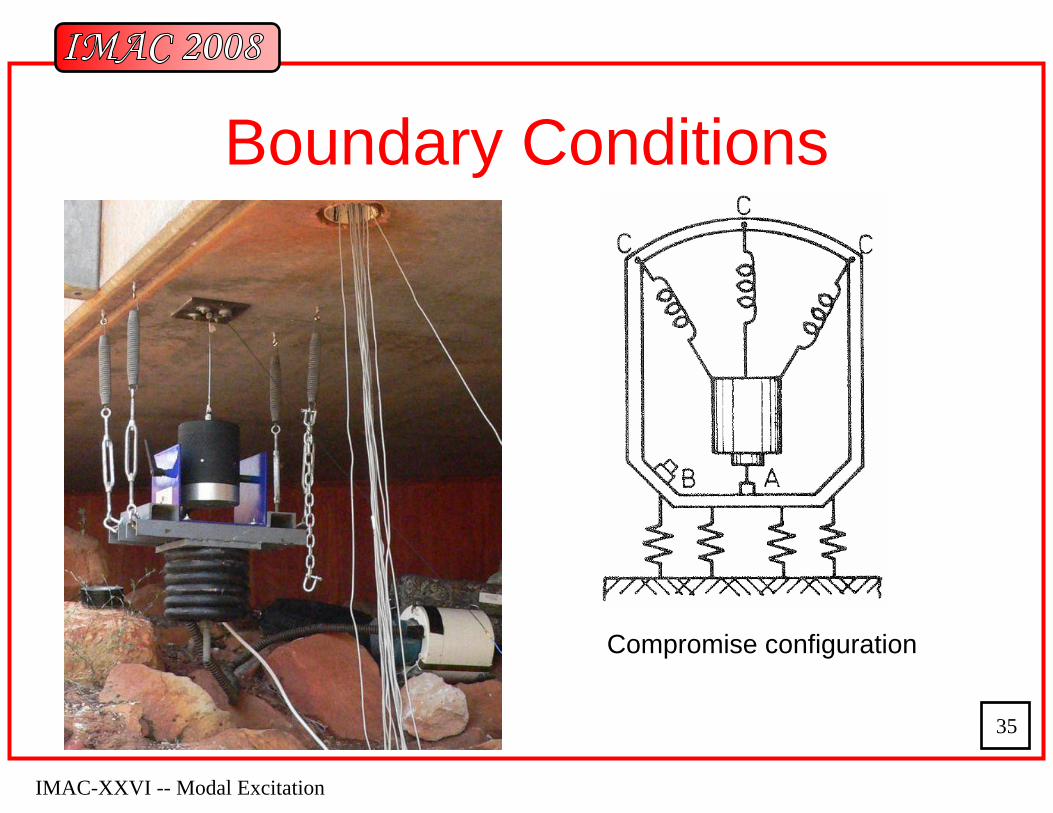
Boundary Conditions
from: Ewins, D. J., Modal Testing: Theory and Practice, pp.101
Unsatisfactory configuration Compromise configuration
Drawings from: Ewins, D. J., Modal Testing: Theory and Practice
IMAC-XXVI -- Modal Excitation
35
Boundary Conditions
Compromise configuration
IMAC-XXVI -- Modal Excitation
36
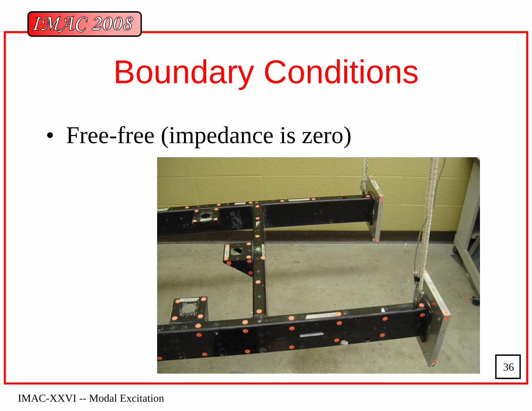
Boundary Conditions
• Free-free (impedance is zero)
IMAC-XXVI -- Modal Excitation
37
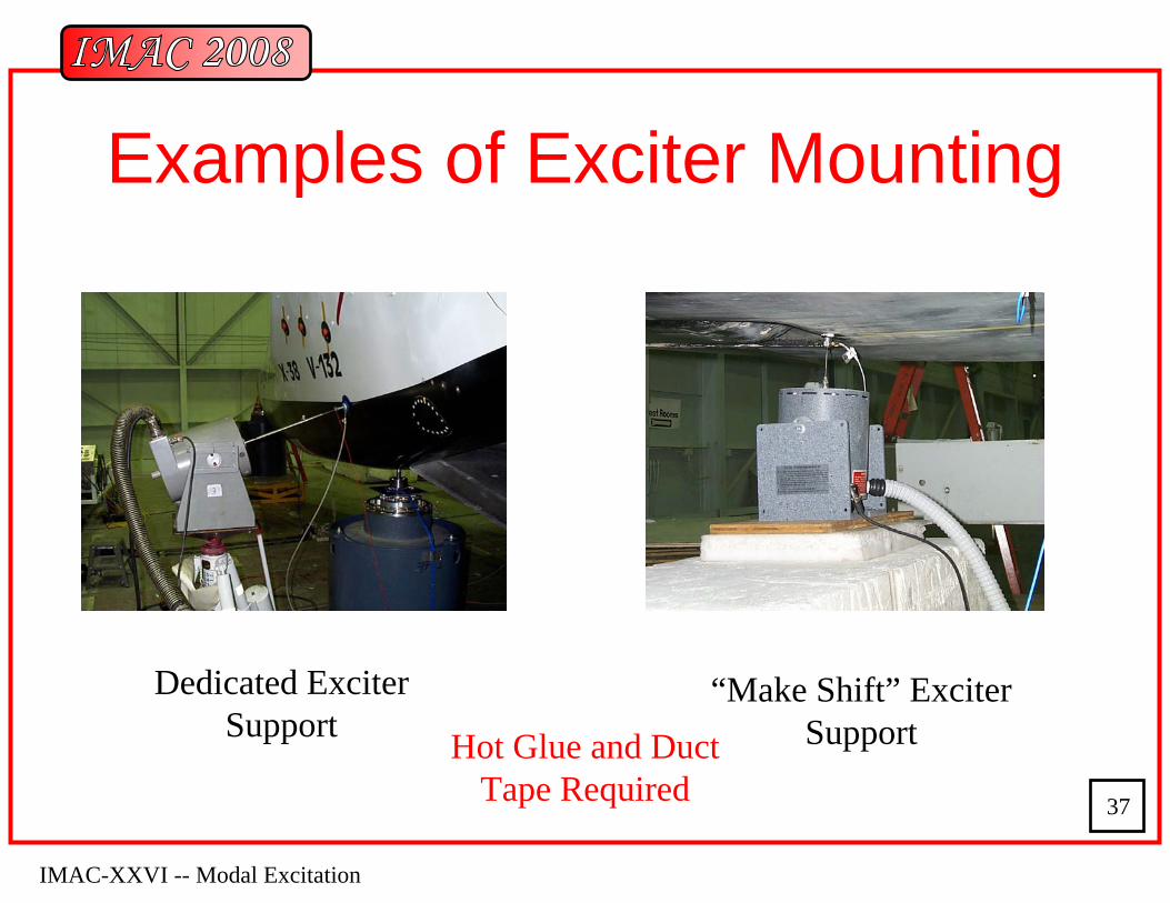
Examples of Exciter Mounting
Dedicated Exciter Support
“Make Shift” Exciter SupportHot Glue and Duct
Tape Required
IMAC-XXVI -- Modal Excitation
38
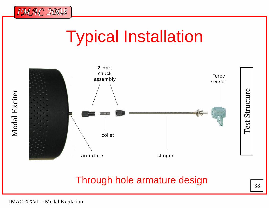
Typical Installation2-part chuck
assembly
armature stinger
Force sensor
collet
Through hole armature design
Mod
al E
xcite
r
Test
Stru
ctur
e
IMAC-XXVI -- Modal Excitation
39
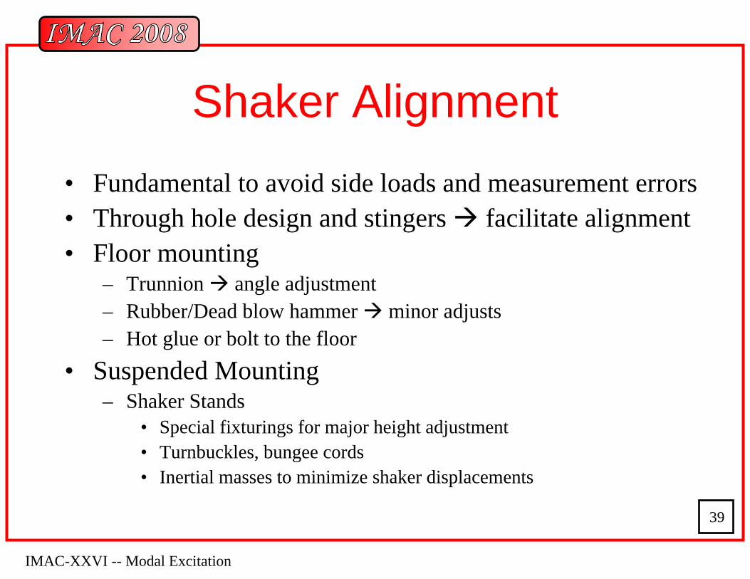
Shaker Alignment• Fundamental to avoid side loads and measurement errors• Through hole design and stingers facilitate alignment• Floor mounting
– Trunnion angle adjustment– Rubber/Dead blow hammer minor adjusts– Hot glue or bolt to the floor
• Suspended Mounting– Shaker Stands
• Special fixturings for major height adjustment• Turnbuckles, bungee cords• Inertial masses to minimize shaker displacements
IMAC-XXVI -- Modal Excitation
40
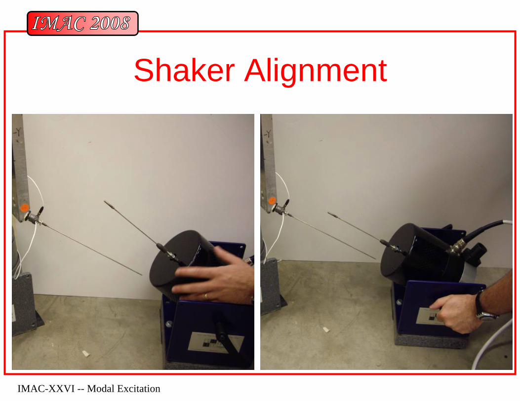
Shaker Alignment
IMAC-XXVI -- Modal Excitation
41
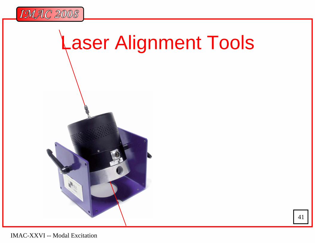
Laser Alignment Tools
IMAC-XXVI -- Modal Excitation
42
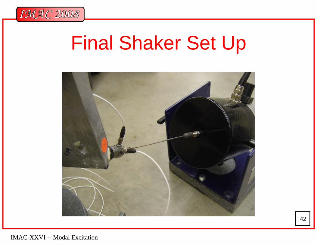
Final Shaker Set Up
IMAC-XXVI -- Modal Excitation
43
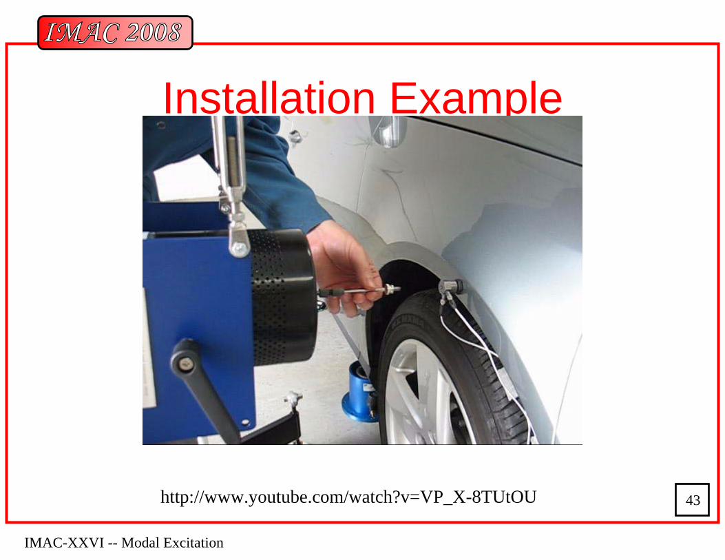
Installation Example
http://www.youtube.com/watch?v=VP_X-8TUtOU
IMAC-XXVI -- Modal Excitation
44
Stingers
• Link between the shaker and the structure• stinger, quill, rods, push-pull rods, etc.• Stiff in the direction of Excitation• Weak in the transverse directions
– No moments or side loads on force transducer– No moments or side loads on shakers
IMAC-XXVI -- Modal Excitation
45
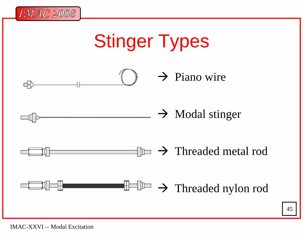
Stinger Types
Piano wire
Modal stinger
Threaded metal rod
Threaded nylon rod
IMAC-XXVI -- Modal Excitation
46
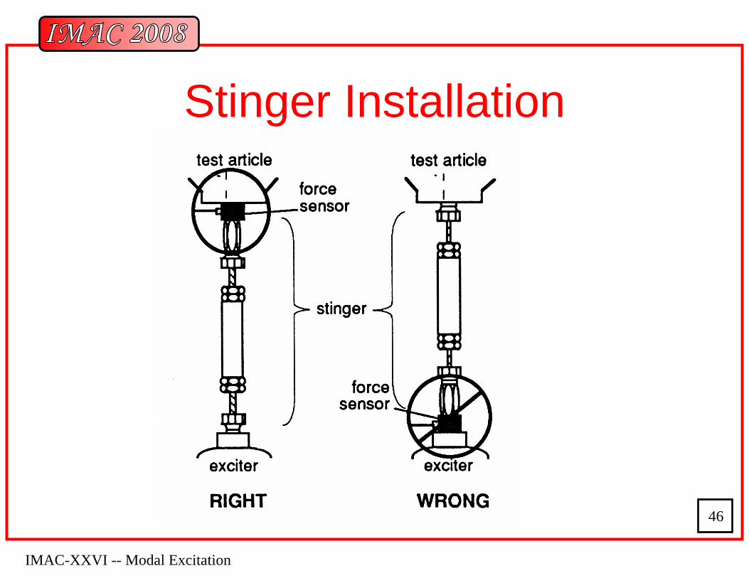
Stinger Installation
IMAC-XXVI -- Modal Excitation
47
Stinger Considerations
• Rigid on excitation direction, weak on transverse direction
• Lightweight• Buckling & alignment
IMAC-XXVI -- Modal Excitation
48
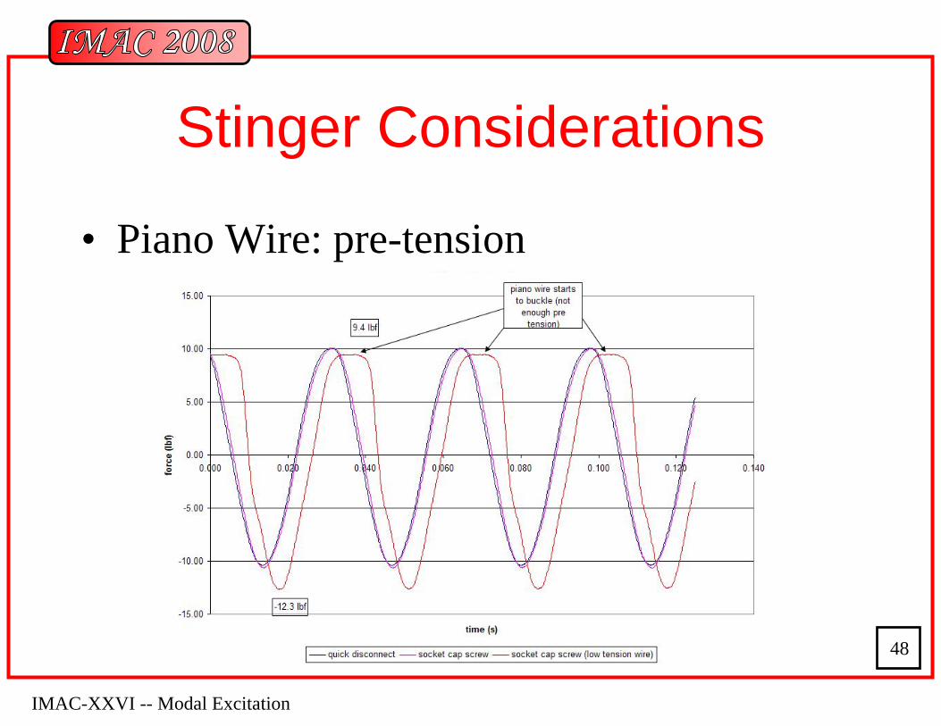
Stinger Considerations
• Piano Wire: pre-tension
IMAC-XXVI -- Modal Excitation
49
Sensor Considerations
• Normally piezoelectric (PE) force sensors are used for measuring excitation and PE accelerometers structure response– broad frequency and dynamic range
• Avoid bottoming mounting studs or stinger to the internal preload stud of the sensor
• Impedance head is a nice option for measuring drive point FRF
IMAC-XXVI -- Modal Excitation
50
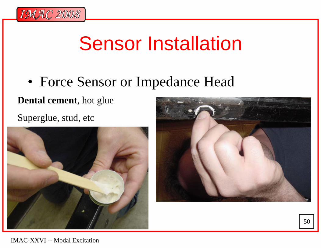
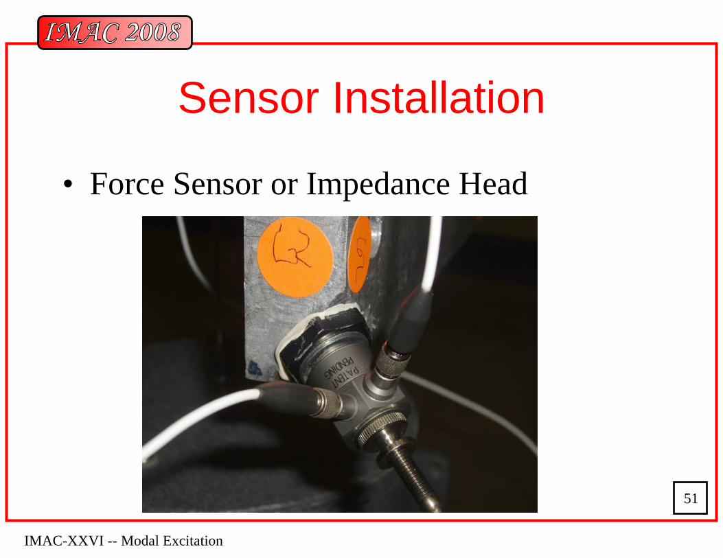
Sensor Installation
• Force Sensor or Impedance HeadDental cement, hot glue
Superglue, stud, etc
IMAC-XXVI -- Modal Excitation
51
Sensor Installation
• Force Sensor or Impedance Head
IMAC-XXVI -- Modal Excitation
52
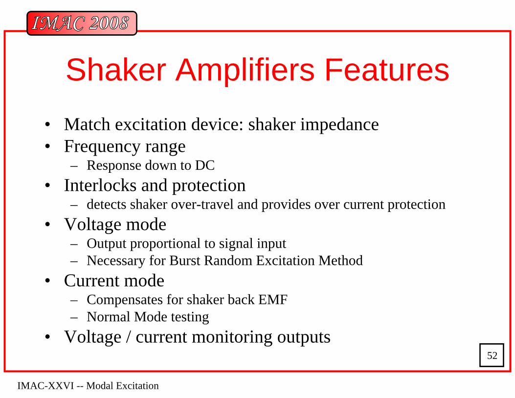
Shaker Amplifiers Features• Match excitation device: shaker impedance• Frequency range
– Response down to DC• Interlocks and protection
– detects shaker over-travel and provides over current protection• Voltage mode
– Output proportional to signal input– Necessary for Burst Random Excitation Method
• Current mode– Compensates for shaker back EMF– Normal Mode testing
• Voltage / current monitoring outputs
IMAC-XXVI -- Modal Excitation
53
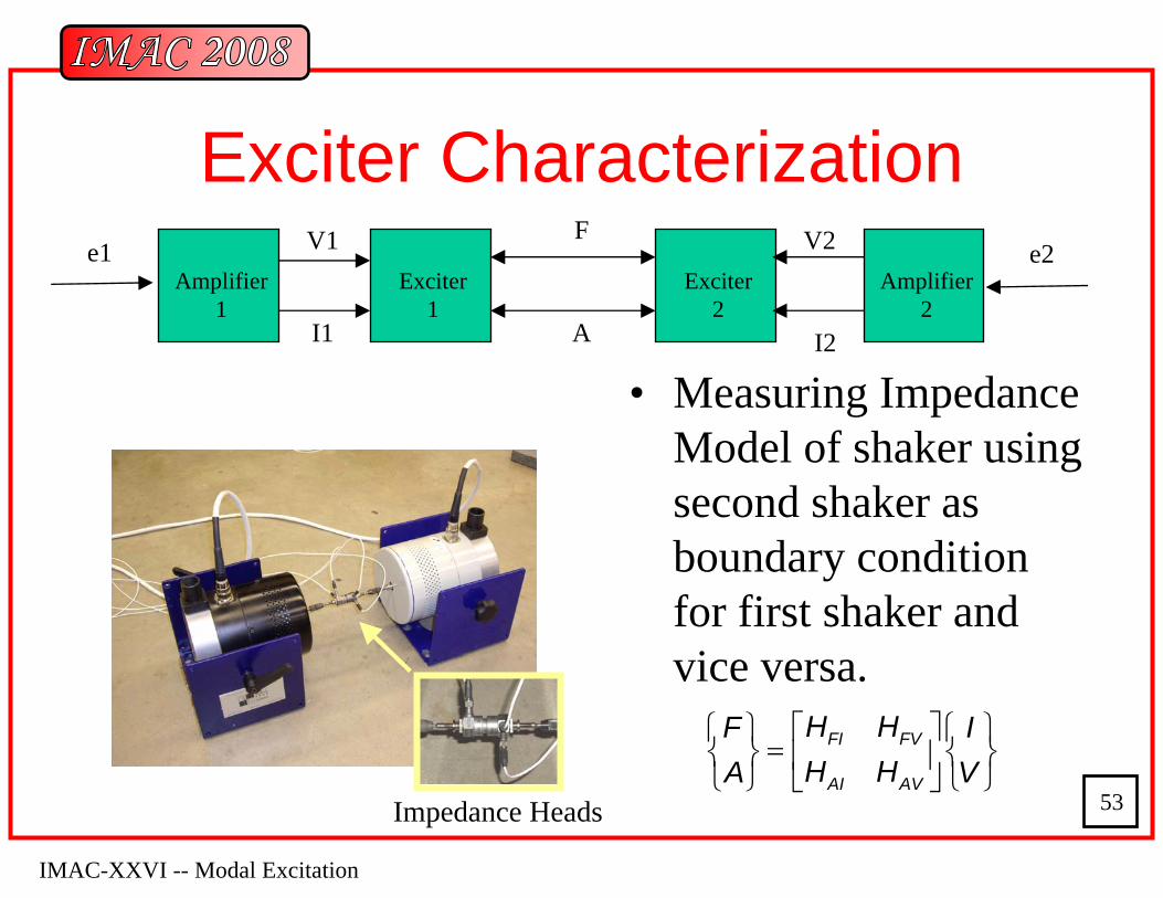
• Measuring Impedance Model of shaker using second shaker as boundary condition for first shaker and vice versa.
Exciter CharacterizationExciter
1
V2
I2
V1Amplifier
1Amplifier
2Exciter
2I1
F
A
e1 e2
FI FV
AI AV
H HF IH HA V⎡ ⎤⎧ ⎫ ⎧ ⎫
=⎨ ⎬ ⎨ ⎬⎢ ⎥⎩ ⎭ ⎩ ⎭⎣ ⎦
Impedance Heads
IMAC-XXVI -- Modal Excitation
54
Testing Configurations
• SISO (Single Input Single Output)• SIMO (Single Input Multiple Output)• MISO (Multiple Input Single Output)• MIMO (Multiple Input Multiple Output)
IMAC-XXVI -- Modal Excitation
55
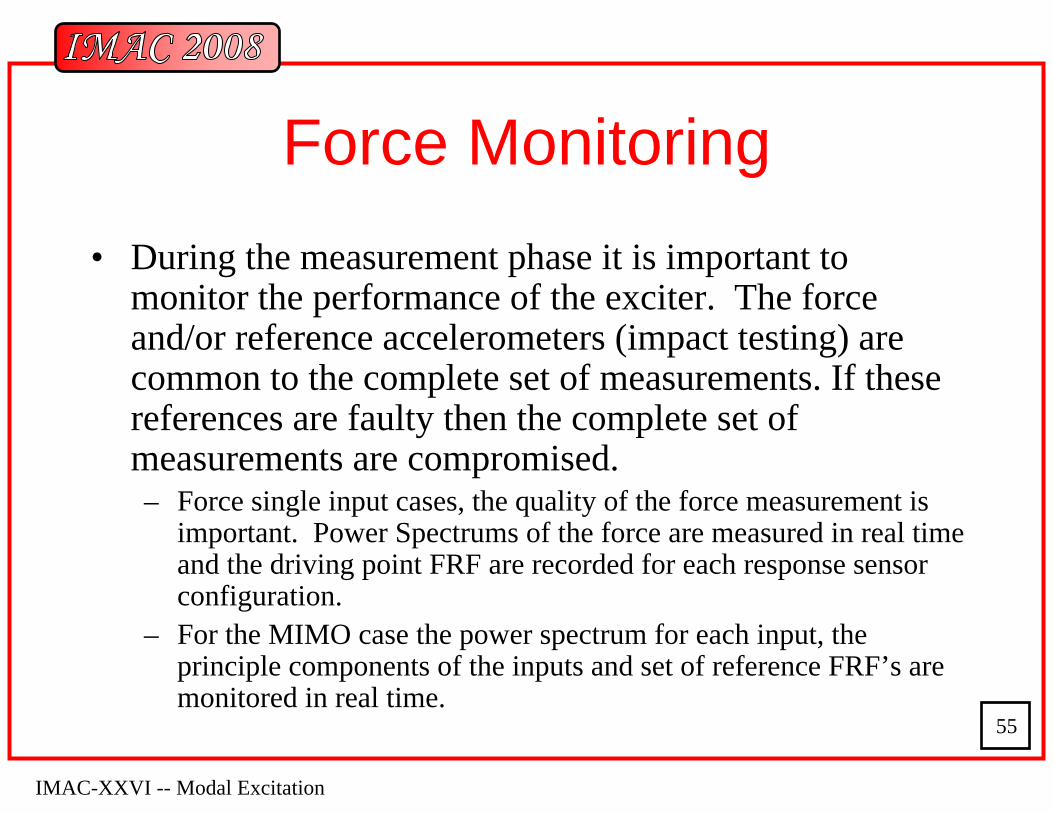
Force Monitoring• During the measurement phase it is important to
monitor the performance of the exciter. The force and/or reference accelerometers (impact testing) are common to the complete set of measurements. If these references are faulty then the complete set of measurements are compromised.– Force single input cases, the quality of the force measurement is
important. Power Spectrums of the force are measured in real time and the driving point FRF are recorded for each response sensor configuration.
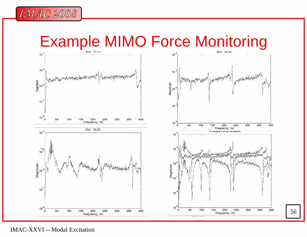
– For the MIMO case the power spectrum for each input, the principle components of the inputs and set of reference FRF’s are monitored in real time.
IMAC-XXVI -- Modal Excitation
56
Example MIMO Force Monitoring
IMAC-XXVI -- Modal Excitation
57
Before Release of Test Item
• At the conclusion of data acquisition phase a quick reduction of the data using a simple modal parameter estimation process should be performed.
• As part of the IMAC Technology center display a MRIT was performed on a simple H-Frame structure and quick CMIF analysis was performed on the measurement data. The result are shown in the following animation of the estimated mode shapes.
Related Documents