1 SCIENTIFIC REPORTS | 5:18130 | DOI: 10.1038/srep18130 www.nature.com/scientificreports IM3D: A parallel Monte Carlo code for efficient simulations of primary radiation displacements and damage in 3D geometry Yong Gang Li 1,2,4 , Yang Yang 2 , Michael P. Short 2 , Ze Jun Ding 3 , Zhi Zeng 1,4 & Ju Li 2 SRIM-like codes have limitations in describing general 3D geometries, for modeling radiation displacements and damage in nanostructured materials. A universal, computationally efficient and massively parallel 3D Monte Carlo code, IM3D, has been developed with excellent parallel scaling performance. IM3D is based on fast indexing of scattering integrals and the SRIM stopping power database, and allows the user a choice of Constructive Solid Geometry (CSG) or Finite Element Triangle Mesh (FETM) method for constructing 3D shapes and microstructures. For 2D films and multilayers, IM3D perfectly reproduces SRIM results, and can be ∼10 2 times faster in serial execution and > 10 4 times faster using parallel computation. For 3D problems, it provides a fast approach for analyzing the spatial distributions of primary displacements and defect generation under ion irradiation. Herein we also provide a detailed discussion of our open-source collision cascade physics engine, revealing the true meaning and limitations of the “Quick Kinchin-Pease” and “Full Cascades” options. The issues of femtosecond to picosecond timescales in defining displacement versus damage, the limitation of the displacements per atom (DPA) unit in quantifying radiation damage (such as inadequacy in quantifying degree of chemical mixing), are discussed. Radiation interaction with matter underlies radiation detectors, ion implantation and focused ion beam etching. Radiation-induced degradation of materials (e.g., void swelling, creep, hardening, embrittlement, radiation-enhanced corrosion, etc.) also presents one of the greatest obstacles to fission/fusion nuclear energy systems 1 . Innovations in nanostructured materials may yield great gains in radiation resistance 2–5 due to their high sink strength originating from the large interface-to-volume ratio, as interfaces/surfaces are efficient venues for the trapping and recombination of radiation-induced mobile point/line defects 6,7 . Recently, many experimental and theoretical studies have been dedicated to engineering the radiation tolerance of different kinds of nanostructured nuclear materials, such as nanocrystals 8–14 , multilayers 15–22 , nanoporous solids 23–26 , nanowires 27–31 , oxide dispersion strengthened (ODS) steels 32–37 , nano-surface reconstruction of plasma-facing materials (PFMs) 38–40 and others 41–43 . Understanding the radiation response of these materials requires precise knowledge of the primary radiation damage induced in their complex three-dimensional (3D) geometries. e displacements per atom (DPA) is the most frequently applied unit to quantify radiation damage 44,45 . e precise definition of DPA is the following: imagine one performs molecular dynamics (MD) simulation with ini- tial temperature T = 0K in the entire material. en, one simulates the ion trajectories precisely starting with an incoming external particle, which can knock atoms out of their original “sites” if their kinetic energy right aſter impact (t = t I ) exceeds E d , the displacement threshold energy, which is defined to be the largest energy barrier to overcome when displacing an atom off-site in an ab initio calculation. ere will be heat generated, but this heat will eventually be conducted or radiated out to the surroundings, and the local temperature falls back to 0 K with no more atom movement. At this “refreezing” point t = t F (which oſten is ~10 1 picoseconds aſter the primary knock-on 1 Key Laboratory for Materials Physics, Institute of Solid State Physics, Chinese Academy of Sciences, Hefei, 230031, China. 2 Department of Nuclear Science and Engineering, Massachusetts Institute of Technology, Cambridge, Massachusetts, 02139, USA. 3 Hefei National Laboratory for Physical Sciences at Microscale and Department of Physics, University of Science and Technology of China, Hefei, 230026, P. R. China. 4 University of Science and Technology of China, Hefei, 230026, P. R. China. Correspondence and requests for materials should be addressed to Z. Z. (email: [email protected]) or M. P. S. (email: [email protected]) or J. L. (email: [email protected]) Received: 19 August 2015 Accepted: 13 November 2015 Published: 11 December 2015 OPEN

Welcome message from author
This document is posted to help you gain knowledge. Please leave a comment to let me know what you think about it! Share it to your friends and learn new things together.
Transcript
1Scientific RepoRts | 5:18130 | DOI: 10.1038/srep18130
www.nature.com/scientificreports
IM3D: A parallel Monte Carlo code for efficient simulations of primary radiation displacements and damage in 3D geometryYong Gang Li1,2,4, Yang Yang2, Michael P. Short2, Ze Jun Ding3, Zhi Zeng1,4 & Ju Li2
SRIM-like codes have limitations in describing general 3D geometries, for modeling radiation displacements and damage in nanostructured materials. A universal, computationally efficient and massively parallel 3D Monte Carlo code, IM3D, has been developed with excellent parallel scaling performance. IM3D is based on fast indexing of scattering integrals and the SRIM stopping power database, and allows the user a choice of Constructive Solid Geometry (CSG) or Finite Element Triangle Mesh (FETM) method for constructing 3D shapes and microstructures. For 2D films and multilayers, IM3D perfectly reproduces SRIM results, and can be ∼102 times faster in serial execution and > 104 times faster using parallel computation. For 3D problems, it provides a fast approach for analyzing the spatial distributions of primary displacements and defect generation under ion irradiation. Herein we also provide a detailed discussion of our open-source collision cascade physics engine, revealing the true meaning and limitations of the “Quick Kinchin-Pease” and “Full Cascades” options. The issues of femtosecond to picosecond timescales in defining displacement versus damage, the limitation of the displacements per atom (DPA) unit in quantifying radiation damage (such as inadequacy in quantifying degree of chemical mixing), are discussed.
Radiation interaction with matter underlies radiation detectors, ion implantation and focused ion beam etching. Radiation-induced degradation of materials (e.g., void swelling, creep, hardening, embrittlement, radiation-enhanced corrosion, etc.) also presents one of the greatest obstacles to fission/fusion nuclear energy systems1. Innovations in nanostructured materials may yield great gains in radiation resistance2–5 due to their high sink strength originating from the large interface-to-volume ratio, as interfaces/surfaces are efficient venues for the trapping and recombination of radiation-induced mobile point/line defects6,7. Recently, many experimental and theoretical studies have been dedicated to engineering the radiation tolerance of different kinds of nanostructured nuclear materials, such as nanocrystals8–14, multilayers15–22, nanoporous solids23–26, nanowires27–31, oxide dispersion strengthened (ODS) steels32–37, nano-surface reconstruction of plasma-facing materials (PFMs)38–40 and others41–43. Understanding the radiation response of these materials requires precise knowledge of the primary radiation damage induced in their complex three-dimensional (3D) geometries.
The displacements per atom (DPA) is the most frequently applied unit to quantify radiation damage44,45. The precise definition of DPA is the following: imagine one performs molecular dynamics (MD) simulation with ini-tial temperature T = 0K in the entire material. Then, one simulates the ion trajectories precisely starting with an incoming external particle, which can knock atoms out of their original “sites” if their kinetic energy right after impact (t = tI) exceeds Ed, the displacement threshold energy, which is defined to be the largest energy barrier to overcome when displacing an atom off-site in an ab initio calculation. There will be heat generated, but this heat will eventually be conducted or radiated out to the surroundings, and the local temperature falls back to 0 K with no more atom movement. At this “refreezing” point t = tF (which often is ~101 picoseconds after the primary knock-on
1Key Laboratory for Materials Physics, Institute of Solid State Physics, Chinese Academy of Sciences, Hefei, 230031, China. 2Department of Nuclear Science and Engineering, Massachusetts Institute of Technology, Cambridge, Massachusetts, 02139, USA. 3Hefei National Laboratory for Physical Sciences at Microscale and Department of Physics, University of Science and Technology of China, Hefei, 230026, P. R. China. 4University of Science and Technology of China, Hefei, 230026, P. R. China. Correspondence and requests for materials should be addressed to Z. Z. (email: [email protected]) or M. P. S. (email: [email protected]) or J. L. (email: [email protected])
Received: 19 August 2015
accepted: 13 November 2015
Published: 11 December 2015
OPEN
www.nature.com/scientificreports/
2Scientific RepoRts | 5:18130 | DOI: 10.1038/srep18130
atom (PKA) event), one compares the refrozen configuration (that no longer evolves) with the t = 0 starting con-figuration. If the starting configuration is a perfect crystal of monatomic, isotopically pure metal, then the DPA counting exercise is simple: one just counts the number of Frenkel pairs to tally the DPA. But for nanostructures with chemical and isotopic variation, spatial gradients, and starting defect populations (interfaces, dislocation tangles, etc.), the definition of DPA is not so trivial. Indeed, consider an arbitrary compound like LiFePO4, trying to completely characterize radiation damage by a single number is a quite difficult order, since there exist a variety of damages to the Li-sublattice, Fe-sublattice, P-sublattice, and O-sublattice, with different long-term implications for material properties. Having said that, if one is to use a single number (DPA) to represent radiation damage, there are still some basic rules one should consider in the counting exercise. First, one does not distinguish between identical atoms. In other words, even though in classical MD we label atoms with numerical index, we do not distinguish between two atoms with the same atomic number (Z) and weight (A) but different index. For example, if one 56Fe atom exchanged with another 56Fe atom before and after the first-principles MD simulation, this should not count toward DPA. This is because despite the word “displacements” in displacements per atom (DPA), DPA is construed as a unit for “damage”, and permutation of two identical atoms does not count toward “damage”, despite radiation-induced primary displacements and heat. If one 56Fe atom exchanged with one 16O atom in a solid at tF, this should most likely count toward DPA since severe chemical damage is likely created at t = tF. There is also the borderline case of one 56Fe atom exchanging with one 57Fe atom before and after: while such isotopic mixing could be physically measureable (for example radiation-enhanced dissolution of an 57Fe inclusion in 56Fe matrix could influence thermal conductivity slightly), the common-sense practice is probably not to count such isotopic exchange toward DPA because not much chemical damage is left at tF.
Using T(t = 0) = 0K MD simulation gives a clean definition of DPA and other possible units of damage, but there are still two problems: (a) what is the bearing of such a definition on reality where T(t) > 0K at t = 0 and beyond, and (b) how to estimate DPA efficiently with SRIM-like Monte Carlo computation (with “Quick Kinchin-Pease” or “Full Cascades” options44,45), as first-principles MD simulations are expensive. For (a), the usual notion is that thermal activation is important for long-term defect evolution after t > tF, but not so much before, so one can take the 0 K MD simulated configuration at t = tF as the initial condition for subsequent evolution, and so the defined DPA should still be a good quantification of damage at t = tF, due to separation of timescales. This argument becomes tricky for liquids, very-high-temperature solids (e.g. superionic materials with for example “molten” Li- or O-sublattice), and glasses, but we will not delve deeper into (a) now. For (b), achieving a reasonably good estimate for radiation damage including DPA at t = tF with much lower computational cost than MD is indeed the central goal of this paper. The short answer is that the “Quick Kinchin-Pease” (QKP) option should give faster and more accurate DPA estimation in SRIM-like codes, including IM3D44. The “Full Cascades” (FC) option is much slower and also tends to give the “wrong” answer44, because FC is meant to give the radiation displacement distribution at t = tI (~fs), not the damage distribution at t = tF (~101 ps). From tI to tF the atomic configuration can still evolve by athermal dynamic recombination/transient annealing effects, that is, if a displaced interstitial atom is not located beyond the spontaneous recombination radius, then the Frenkel pair can still dynamically recombine even at 0 K, or during the transient thermal spike before refreezing. Thus, if one were to take one FC displacement-off-site event to mean one damage event seen at t = tF (which would be wrong), SRIM FC would provide an overestimated “DPA” by a factor of around two compared to the QKP option and MD benchmark44. For most users of SRIM-like codes whose intent is to get damage/DPA numbers close to the first-principles MD definition, the “Quick Kinchin-Pease” (QKP) option is much preferred. The FC option is like an “open heart surgery” option for experienced developers who would like to understand more about the difference between radiation displacements and damage, and the limitations of a single value DPA in quantifying damage. In principle, it should be possible to evolve FC displace-ments distribution at t = tI (~fs) to QKP-like damage distribution at t = tF (~101 ps), taking effects like athermal recombination and transient annealing into account approximately with reasonable fidelity. Unfortunately, at present the physics engine for such tI-to-tF evolution is not well developed at all, so presenting the FC-option result in any form should be taken with extreme caution.
IM3D OverviewIon irradiation has been widely applied to study high-DPA radiation effects in structural materials46, including changes in material microstructure, local properties, dose rate effects, retention of H/He atoms, surface erosion in PFMs47, etc. All these radiation effects in crystals originate with the direct, primary production of atomic-scale point defects, consisting of vacancies, interstitial atoms, anti-site defects, and clusters. The accumulation and migration of these atomic defects directly results in the degradation of key material properties by numerous mechanisms, such as amorphization, phase and blister formation, void swelling, irradiation-induced creep, and radiation enhanced corrosion. In comparison to bulk materials, the irradiation of nanostructures often results in far less damage accumulation, because the size of a single, ballistic collision cascade (10−9–10−8 m) is comparable to the size of the nano-features48. For a small sample size in one or more dimensions like nanowires or 2D materi-als, only a small part of the projectile energy is deposited in the object, while both the sputtering yield and defect annealing are enhanced by the high surface-to-volume ratio7. Therefore, new computational implementations and a careful re-examination of the underlying physics are duly required for the modeling of the radiation effects in 3D nanostructured materials.
Despite the fact that the commonly used unit of radiation damage (DPA) is defined by first-principles MD simulation, Monte Carlo (MC) codes are very frequently used to simulate radiation damage, due to their high computational efficiency, accounting of electronic energy loss and multiple- and plural-scattering, and no lim-itations in nanostructure size, ion energy, or availability of empirical interatomic potentials7,49–51. Mayer et al. pointed out that the agreement between MC and MD is quite good for angular and energy distributions for the multiple small angle scattering of MeV ions50. MC methods are generally accurate enough to estimate the amount of ion deposition and primary radiation damage, at least in the validated ion energy range of the binary collision
www.nature.com/scientificreports/
3Scientific RepoRts | 5:18130 | DOI: 10.1038/srep18130
approximation and for ion fluences that do not produce severe amorphization, if the distinction between “Quick Kinchin-Pease” (QKP option for damage) and “Full Cascades” (FC option for modeling fs-scale off-lattice-site displacements) option is made, as noted in the Introduction section.
The accuracy of MC simulation codes depends critically on the accuracy of the underlying models and databases of radiation stopping power, as well as the specific implementation algorithms. SRIM (Stopping and Range of Ions in Matter) has been the de facto standard for stopping power calculations for more than 30 years, including single elements with atomic numbers from 1–92 and energy ranges of 10 eV-2 GeV/amu45. Paul also pointed out that SRIM and MSTAR (a program that can predict stopping powers for ions from 3Li to 18Ar) describe experimental data best over a wide range of targets and energies in general, by comparing recent stopping power tables for dif-ferent kinds of ions with experimental data52,53. Since 2003, a self-contained SRIM module “SRModule.exe” has been published with SRIM54, which allows for the easy integration of SRIM’s stopping power database into external programs, thus promoting the development of new ion-matter interaction codes.
Computational efficiency is the raison d'être as well as major performance metric of the MC approach, which specifically occurs in the calculation of the classical binary atomic scattering angle (θCM) expressed as an integral in the center-of-mass coordinate system51. SRIM-like codes use the MAGIC algorithm to compute θCM consider-ing a screened Coulomb potential, which is already an improvement by at least two orders of magnitude over the direct computation of the scattering integral while sacrificing little accuracy45. Database interpolation has been improved by Yuan et al.55 and Schiettekatte56, by a fast indexing technique of exploiting the binary representation of floating-point numbers to index tables (including scattering angle components and even stopping power) in log-scale without explicitly computing log-function. These techniques exhibit a significant speed gain by several orders of magnitude compared to the MAGIC algorithm with nearly no loss of accuracy49,56.
SRIM/TRIM45 has been a serial instruction code, and only applies to thin films and multilayers7. Geometrically complex targets were usually simulated as a finite stack of two-dimensional, compositionally homogeneous material layers7. This works approximately as long as the size of a radiation cascade (10−9–10−8 m) is much smaller than the size of the microstructure, but clearly breaks down for nanostructures whose geometrical sizes are compara-ble to that of a single cascade. Other codes have treated limited 3D cases49,51,57,58, but their computational power needs to be enhanced to meet the demands of complex 3D geometries with many domains and interfaces, and parallelization is needed. IM3D is the first parallelized MC code for general 3D structures, and demonstrates good parallel scaling performance.
In the past a simple 3D framework based on the construction of equal-sized rectangular cells has been intro-duced49,59. However, this type of 3D geometric model has limitations. For example, the stepped planes of the cellular geometry can distort the sputtering yield, causing atoms to re-enter the target and create further sputtering/defects. There is no correction of the step change in electronic stopping power between the cell boundaries. In addition, there are domain size adaptivity and scaling issues49,59.
Thus, it is necessary to develop a more general and robust approach in constructing arbitrarily complex 3D nanostructures. The flexibility of the geometry description “language” and the corresponding optimization of the ion tracing procedure within the material structure are certainly the two most important aspects of a 3D model. In past years, we have successfully implemented the Constructive Solid Geometry (CSG)60,61 and Finite Element Triangle Mesh (FETM) computational geometry libraries62,63 to efficiently simulate particle transport in arbitrary 3D geometries64,65. In this paper, we introduce IM3D (Irradiated Microstructures in 3D), which uses the fast database indexing technique56 on the scattering angle and standard physical parameters such as electronic stop-ping powers generated using “SRModule.exe”54, with the user’s choice of CSG/FETM library as the 3D structural description64,65. The code is implemented with the Message Passing Interface (MPI) library, with excellent parallel scaling performance on Beowulf clusters (up to 105 times faster than serial-instruction SRIM executable). We have also compared IM3D results with SRIM in both QKP and FC options for 1D benchmark cases, and have demonstrated very close numerical agreement. An added benefit is that the collision physics engine of IM3D is open source66,67 and can be modified at will.
In the following, the framework of IM3D will be first described, followed by a number of illustrative examples of using IM3D to simulate geometrically complex nanostructures. Both “Quick Kinchin-Pease” (QKP option for damage) and “Full Cascades” (FC option for modeling fs-timescale off-lattice-site displacements) options are described in detail.
IM3D Program Description. IM3D is a massively parallel, open-source, 3D MC code for simulating the transport of ions and the production of defects within materials. It can model arbitrarily complex 3D targets made of different geometric elements, each composed of different materials. Both the 3D distribution of ions and the material evolution associated with the ion’s energy loss, such as displacement, sputtering, damage, ionization, and phonon production, can be modeled by IM3D with local rules. The FC option in IM3D allows one to follow all target atom cascades in detail, and the open-source platform of IM3D allows one to modify the detailed local rules. Output parameters include electronic and nuclear energy deposition, back-scattering/implanted ions, radiation damage in DPA, point defect concentrations, and sputtered atoms, etc. Output files are in the format of .cfg, .msh or .vtk, which can be viewed by software such as AtomEye68, Gmsh69 and ParaView70.
IM3D consists of three major components: 1) physical models of ion-atom collisions, 2) universal 3D structural models, and 3) efficient computational algorithms.
Physical models. IM3D’s collision physics are similar to well-established SRIM-like codes, which employ the random phase approximation (RPA), the binary collision approximation (BCA) and the central potential approx-imation (CPA)45,56,71. The code computes random trajectories of ions to present statistically meaningful data. Each trajectory corresponds to a particle (ion or knocked target atom) with a specified starting position, a given direction,
www.nature.com/scientificreports/
4Scientific RepoRts | 5:18130 | DOI: 10.1038/srep18130
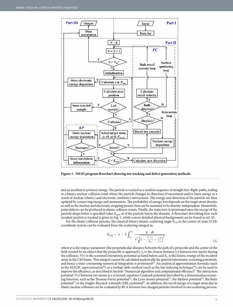
and an incident or primary energy. The particle is tracked as a random sequence of straight free-flight-paths, ending in a binary nuclear collision event where the particle changes its direction of movement and/or loses energy as a result of nuclear (elastic) and electronic (inelastic) interactions. The energy and direction of the particle are then updated by conserving energy and momentum. The probability of energy loss depends on the target atom density, as well as the nuclear and electronic stopping powers that can be assumed to be density-independent. Meanwhile, point defects can be produced in elastic collision events. Finally, the trajectory is terminated once the energy of the particle drops below a specified value Emin, or if the particle leaves the domain. A flowchart describing how each incident particle is tracked is given in Fig. 1, while a more detailed physical background can be found in ref. 45.
For the elastic collision process, the classical binary atomic scattering angle θCM in the center-of-mass (CM) coordinate system can be evaluated from the scattering integral as,
∫( )
θ = π −⋅
− − ( )
∞
( )
p dr
r2
1 1r V r
Epr
CM2 20
C
where p is the impact parameter (the perpendicular distance between the path of a projectile and the center of the field created by an object that the projectile is approach), r0 is the closest distance (r) between two nuclei during the collision, V(r) is the screened interatomic potential as listed below, and EC is the kinetic energy of the incident atom in the CM frame. This integral cannot be calculated analytically for general interatomic screening potentials, and hence a time-consuming numerical integration is performed45. An analytical approximation formula (such as the MAGIC approximation45) or a lookup table method (such as the fast indexing technique56) can be used to improve the efficiency, as described in Section “Numerical algorithm and computational efficiency”. The interaction potential V(r) between two atoms is a screened, repulsive Coulomb potential described by a dimensionless screen-ing function, such as the Thomas-Fermi potential72, the Lenz-Jensen potential73, the Moliere potential74, the Bohr potential75 or the Ziegler-Biersack-Littmark (ZBL) potential45. In addition, the recoil energy of a target atom due to elastic nuclear collisions can be evaluated by BCA between two charged particles involved in one scattering process.
Figure 1. IM3D program flowchart showing ion tracking and defect generation methods.
www.nature.com/scientificreports/
5Scientific RepoRts | 5:18130 | DOI: 10.1038/srep18130
For the inelastic collision process, the ion energy decreases uniformly along the free-flight-paths through elec-tronic energy losses, accounting for energy straggling. In IM3D, physical parameters such as electronic stopping powers are generated using “SRModule.exe” provided by SRIM54. These are provided in the form of pre-calculated tables as implemented in Corteo56. Either the Bohr76, Chu77, or Yang78 formulas can be selected to account for energy straggling. Furthermore, IM3D also employs a linear mixing of stopping powers (known as Bragg’s rule79) for determining the total stopping power in alloys and compounds.
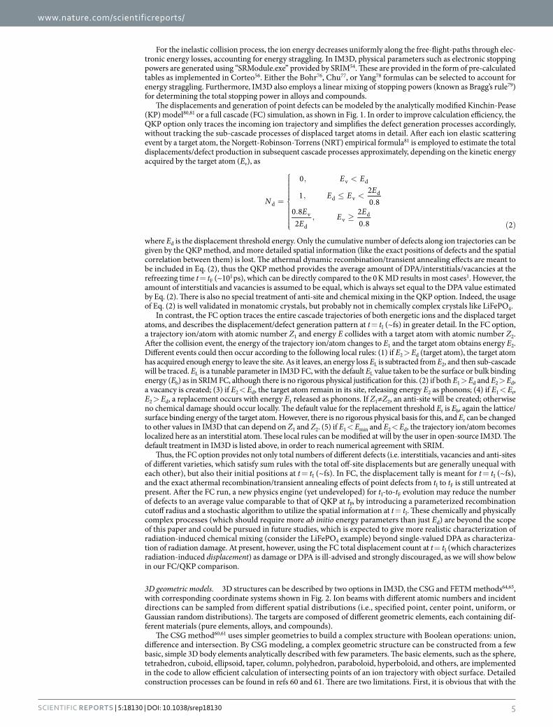
The displacements and generation of point defects can be modeled by the analytically modified Kinchin-Pease (KP) model80,81 or a full cascade (FC) simulation, as shown in Fig. 1. In order to improve calculation efficiency, the QKP option only traces the incoming ion trajectory and simplifies the defect generation processes accordingly, without tracking the sub-cascade processes of displaced target atoms in detail. After each ion elastic scattering event by a target atom, the Norgett-Robinson-Torrens (NRT) empirical formula81 is employed to estimate the total displacements/defect production in subsequent cascade processes approximately, depending on the kinetic energy acquired by the target atom (Ev), as
=
, <
, ≤ <.
., ≥
. ( )
N
E E
E E E
EE
E E
0
1 20 8
0 82
20 8 2
d
v d
d vd
v
dv
d
where Ed is the displacement threshold energy. Only the cumulative number of defects along ion trajectories can be given by the QKP method, and more detailed spatial information (like the exact positions of defects and the spatial correlation between them) is lost. The athermal dynamic recombination/transient annealing effects are meant to be included in Eq. (2), thus the QKP method provides the average amount of DPA/interstitials/vacancies at the refreezing time t = tF (~101 ps), which can be directly compared to the 0 K MD results in most cases1. However, the amount of interstitials and vacancies is assumed to be equal, which is always set equal to the DPA value estimated by Eq. (2). There is also no special treatment of anti-site and chemical mixing in the QKP option. Indeed, the usage of Eq. (2) is well validated in monatomic crystals, but probably not in chemically complex crystals like LiFePO4.
In contrast, the FC option traces the entire cascade trajectories of both energetic ions and the displaced target atoms, and describes the displacement/defect generation pattern at t = tI (~fs) in greater detail. In the FC option, a trajectory ion/atom with atomic number Z1 and energy E collides with a target atom with atomic number Z2. After the collision event, the energy of the trajectory ion/atom changes to E1 and the target atom obtains energy E2. Different events could then occur according to the following local rules: (1) if E2 > Ed (target atom), the target atom has acquired enough energy to leave the site. As it leaves, an energy loss EL is subtracted from E2, and then sub-cascade will be traced. EL is a tunable parameter in IM3D FC, with the default EL value taken to be the surface or bulk binding energy (Eb) as in SRIM FC, although there is no rigorous physical justification for this. (2) if both E1 > Ed and E2 > Ed, a vacancy is created; (3) if E2 < Ed, the target atom remain in its site, releasing energy E2 as phonons; (4) if E1 < Er, E2 > Ed, a replacement occurs with energy E1 released as phonons. If Z1≠Z2, an anti-site will be created; otherwise no chemical damage should occur locally. The default value for the replacement threshold Er is Eb, again the lattice/surface binding energy of the target atom. However, there is no rigorous physical basis for this, and Er can be changed to other values in IM3D that can depend on Z1 and Z2. (5) if E1 < Emin and E2 < Ed, the trajectory ion/atom becomes localized here as an interstitial atom. These local rules can be modified at will by the user in open-source IM3D. The default treatment in IM3D is listed above, in order to reach numerical agreement with SRIM.
Thus, the FC option provides not only total numbers of different defects (i.e. interstitials, vacancies and anti-sites of different varieties, which satisfy sum rules with the total off-site displacements but are generally unequal with each other), but also their initial positions at t = tI (~fs). In FC, the displacement tally is meant for t = tI (~fs), and the exact athermal recombination/transient annealing effects of point defects from tI to tF is still untreated at present. After the FC run, a new physics engine (yet undeveloped) for tI-to-tF evolution may reduce the number of defects to an average value comparable to that of QKP at tF, by introducing a parameterized recombination cutoff radius and a stochastic algorithm to utilize the spatial information at t = tI. These chemically and physically complex processes (which should require more ab initio energy parameters than just Ed) are beyond the scope of this paper and could be pursued in future studies, which is expected to give more realistic characterization of radiation-induced chemical mixing (consider the LiFePO4 example) beyond single-valued DPA as characteriza-tion of radiation damage. At present, however, using the FC total displacement count at t = tI (which characterizes radiation-induced displacement) as damage or DPA is ill-advised and strongly discouraged, as we will show below in our FC/QKP comparison.
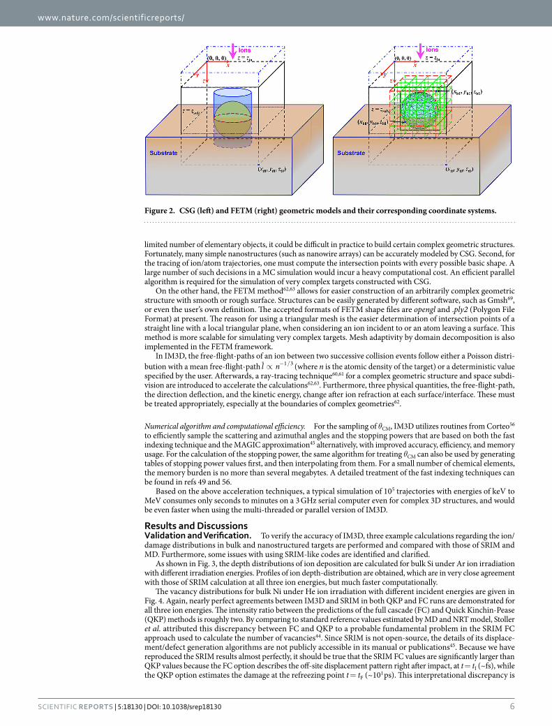
3D geometric models. 3D structures can be described by two options in IM3D, the CSG and FETM methods64,65, with corresponding coordinate systems shown in Fig. 2. Ion beams with different atomic numbers and incident directions can be sampled from different spatial distributions (i.e., specified point, center point, uniform, or Gaussian random distributions). The targets are composed of different geometric elements, each containing dif-ferent materials (pure elements, alloys, and compounds).
The CSG method60,61 uses simpler geometries to build a complex structure with Boolean operations: union, difference and intersection. By CSG modeling, a complex geometric structure can be constructed from a few basic, simple 3D body elements analytically described with few parameters. The basic elements, such as the sphere, tetrahedron, cuboid, ellipsoid, taper, column, polyhedron, paraboloid, hyperboloid, and others, are implemented in the code to allow efficient calculation of intersecting points of an ion trajectory with object surface. Detailed construction processes can be found in refs 60 and 61. There are two limitations. First, it is obvious that with the
www.nature.com/scientificreports/
6Scientific RepoRts | 5:18130 | DOI: 10.1038/srep18130
limited number of elementary objects, it could be difficult in practice to build certain complex geometric structures. Fortunately, many simple nanostructures (such as nanowire arrays) can be accurately modeled by CSG. Second, for the tracing of ion/atom trajectories, one must compute the intersection points with every possible basic shape. A large number of such decisions in a MC simulation would incur a heavy computational cost. An efficient parallel algorithm is required for the simulation of very complex targets constructed with CSG.
On the other hand, the FETM method62,63 allows for easier construction of an arbitrarily complex geometric structure with smooth or rough surface. Structures can be easily generated by different software, such as Gmsh69, or even the user’s own definition. The accepted formats of FETM shape files are opengl and .ply2 (Polygon File Format) at present. The reason for using a triangular mesh is the easier determination of intersection points of a straight line with a local triangular plane, when considering an ion incident to or an atom leaving a surface. This method is more scalable for simulating very complex targets. Mesh adaptivity by domain decomposition is also implemented in the FETM framework.
In IM3D, the free-flight-paths of an ion between two successive collision events follow either a Poisson distri-bution with a mean free-flight-path ∝ − /l n 1 3 (where n is the atomic density of the target) or a deterministic value specified by the user. Afterwards, a ray-tracing technique60,61 for a complex geometric structure and space subdi-vision are introduced to accelerate the calculations62,63. Furthermore, three physical quantities, the free-flight-path, the direction deflection, and the kinetic energy, change after ion refraction at each surface/interface. These must be treated appropriately, especially at the boundaries of complex geometries62.
Numerical algorithm and computational efficiency. For the sampling of θCM, IM3D utilizes routines from Corteo56 to efficiently sample the scattering and azimuthal angles and the stopping powers that are based on both the fast indexing technique and the MAGIC approximation45 alternatively, with improved accuracy, efficiency, and memory usage. For the calculation of the stopping power, the same algorithm for treating θCM can also be used by generating tables of stopping power values first, and then interpolating from them. For a small number of chemical elements, the memory burden is no more than several megabytes. A detailed treatment of the fast indexing techniques can be found in refs 49 and 56.
Based on the above acceleration techniques, a typical simulation of 105 trajectories with energies of keV to MeV consumes only seconds to minutes on a 3 GHz serial computer even for complex 3D structures, and would be even faster when using the multi-threaded or parallel version of IM3D.
Results and DiscussionsValidation and Verification. To verify the accuracy of IM3D, three example calculations regarding the ion/damage distributions in bulk and nanostructured targets are performed and compared with those of SRIM and MD. Furthermore, some issues with using SRIM-like codes are identified and clarified.
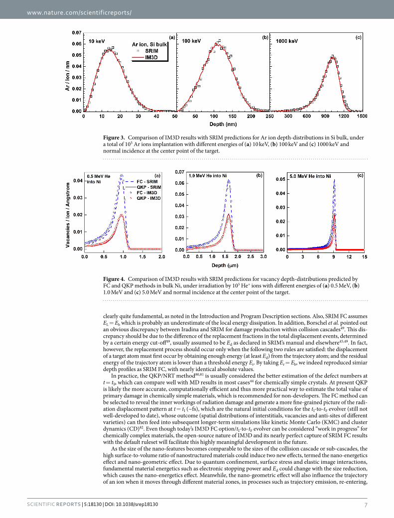
As shown in Fig. 3, the depth distributions of ion deposition are calculated for bulk Si under Ar ion irradiation with different irradiation energies. Profiles of ion depth-distribution are obtained, which are in very close agreement with those of SRIM calculation at all three ion energies, but much faster computationally.
The vacancy distributions for bulk Ni under He ion irradiation with different incident energies are given in Fig. 4. Again, nearly perfect agreements between IM3D and SRIM in both QKP and FC runs are demonstrated for all three ion energies. The intensity ratio between the predictions of the full cascade (FC) and Quick Kinchin-Pease (QKP) methods is roughly two. By comparing to standard reference values estimated by MD and NRT model, Stoller et al. attributed this discrepancy between FC and QKP to a probable fundamental problem in the SRIM FC approach used to calculate the number of vacancies44. Since SRIM is not open-source, the details of its displace-ment/defect generation algorithms are not publicly accessible in its manual or publications45. Because we have reproduced the SRIM results almost perfectly, it should be true that the SRIM FC values are significantly larger than QKP values because the FC option describes the off-site displacement pattern right after impact, at t = tI (~fs), while the QKP option estimates the damage at the refreezing point t = tF (~101 ps). This interpretational discrepancy is
Figure 2. CSG (left) and FETM (right) geometric models and their corresponding coordinate systems.
www.nature.com/scientificreports/
7Scientific RepoRts | 5:18130 | DOI: 10.1038/srep18130
clearly quite fundamental, as noted in the Introduction and Program Description sections. Also, SRIM FC assumes EL = Eb which is probably an underestimate of the local energy dissipation. In addition, Borschel et al. pointed out an obvious discrepancy between Iradina and SRIM for damage production within collision cascades49. This dis-crepancy should be due to the difference of the replacement fractions in the total displacement events, determined by a certain energy cut-off49, usually assumed to be Ed as declared in SRIM’s manual and elsewhere45,49. In fact, however, the replacement process should occur only when the following two rules are satisfied: the displacement of a target atom must first occur by obtaining enough energy (at least Ed) from the trajectory atom; and the residual energy of the trajectory atom is lower than a threshold energy Er. By taking Er = Eb, we indeed reproduced simiar depth profiles as SRIM FC, with nearly identical absolute values.
In practice, the QKP/NRT method80,81 is usually considered the better estimation of the defect numbers at t = tF, which can compare well with MD results in most cases44 for chemically simple crystals. At present QKP is likely the more accurate, computationally efficient and thus more practical way to estimate the total value of primary damage in chemically simple materials, which is recommended for non-developers. The FC method can be selected to reveal the inner workings of radiation damage and generate a more fine-grained picture of the radi-ation displacement pattern at t = tI (~fs), which are the natural initial conditions for the tI-to-tF evolver (still not well-developed to date), whose outcome (spatial distributions of interstitials, vacancies and anti-sites of different varieties) can then feed into subsequent longer-term simulations like kinetic Monte Carlo (KMC) and cluster dynamics (CD)82. Even though today’s IM3D FC option/tI-to-tF evolver can be considered “work in progress” for chemically complex materials, the open-source nature of IM3D and its nearly perfect capture of SRIM FC results with the default ruleset will facilitate this highly meaningful development in the future.
As the size of the nano-features becomes comparable to the sizes of the collision cascade or sub-cascades, the high surface-to-volume ratio of nanostructured materials could induce two new effects, termed the nano-energetics effect and nano-geometric effect. Due to quantum confinement, surface stress and elastic image interactions, fundamental material energetics such as electronic stopping power and Ed could change with the size reduction, which causes the nano-energetics effect. Meanwhile, the nano-geometric effect will also influence the trajectory of an ion when it moves through different material zones, in processes such as trajectory emission, re-entering,
Figure 3. Comparison of IM3D results with SRIM predictions for Ar ion depth-distributions in Si bulk, under a total of 105 Ar ions implantation with different energies of (a) 10 keV, (b) 100 keV and (c) 1000 keV and normal incidence at the center point of the target.
Figure 4. Comparison of IM3D results with SRIM predictions for vacancy depth-distributions predicted by FC and QKP methods in bulk Ni, under irradiation by 105 He+ ions with different energies of (a) 0.5 MeV, (b) 1.0 MeV and (c) 5.0 MeV and normal incidence at the center point of the target.
www.nature.com/scientificreports/
8Scientific RepoRts | 5:18130 | DOI: 10.1038/srep18130
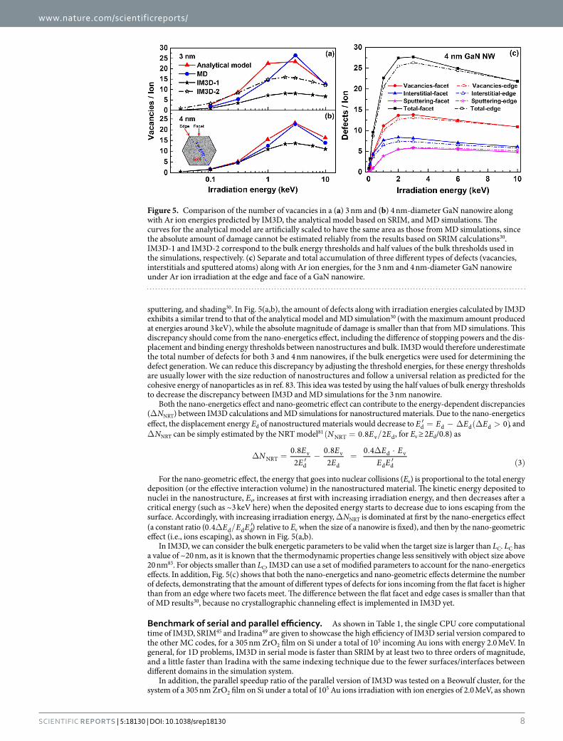
sputtering, and shading30. In Fig. 5(a,b), the amount of defects along with irradiation energies calculated by IM3D exhibits a similar trend to that of the analytical model and MD simulation30 (with the maximum amount produced at energies around 3 keV), while the absolute magnitude of damage is smaller than that from MD simulations. This discrepancy should come from the nano-energetics effect, including the difference of stopping powers and the dis-placement and binding energy thresholds between nanostructures and bulk. IM3D would therefore underestimate the total number of defects for both 3 and 4 nm nanowires, if the bulk energetics were used for determining the defect generation. We can reduce this discrepancy by adjusting the threshold energies, for these energy thresholds are usually lower with the size reduction of nanostructures and follow a universal relation as predicted for the cohesive energy of nanoparticles as in ref. 83. This idea was tested by using the half values of bulk energy thresholds to decrease the discrepancy between IM3D and MD simulations for the 3 nm nanowire.
Both the nano-energetics effect and nano-geometric effect can contribute to the energy-dependent discrepancies (Δ NNRT) between IM3D calculations and MD simulations for nanostructured materials. Due to the nano-energetics effect, the displacement energy Ed of nanostructured materials would decrease to ′ = − ∆ (∆ > )E E E E 0d d d d , and Δ NNRT can be simply estimated by the NRT model81 ( = . / )N E E0 8 2NRT v d, for Ev ≥ 2Ed/0.8) as
∆ =.′−.
=. ∆ ⋅
′ ( )N E
EE
EE E
E E0 82
0 82
0 43NRT
v
d
v
d
d v
d d
For the nano-geometric effect, the energy that goes into nuclear collisions (Ev) is proportional to the total energy deposition (or the effective interaction volume) in the nanostructured material. The kinetic energy deposited to nuclei in the nanostructure, Ev, increases at first with increasing irradiation energy, and then decreases after a critical energy (such as ~3 keV here) when the deposited energy starts to decrease due to ions escaping from the surface. Accordingly, with increasing irradiation energy, Δ NNRT is dominated at first by the nano-energetics effect (a constant ratio ( . ∆ / ′E E E0 4 d d d) relative to Ev when the size of a nanowire is fixed), and then by the nano-geometric effect (i.e., ions escaping), as shown in Fig. 5(a,b).
In IM3D, we can consider the bulk energetic parameters to be valid when the target size is larger than LC. LC has a value of ~20 nm, as it is known that the thermodynamic properties change less sensitively with object size above 20 nm83. For objects smaller than LC, IM3D can use a set of modified parameters to account for the nano-energetics effects. In addition, Fig. 5(c) shows that both the nano-energetics and nano-geometric effects determine the number of defects, demonstrating that the amount of different types of defects for ions incoming from the flat facet is higher than from an edge where two facets meet. The difference between the flat facet and edge cases is smaller than that of MD results30, because no crystallographic channeling effect is implemented in IM3D yet.
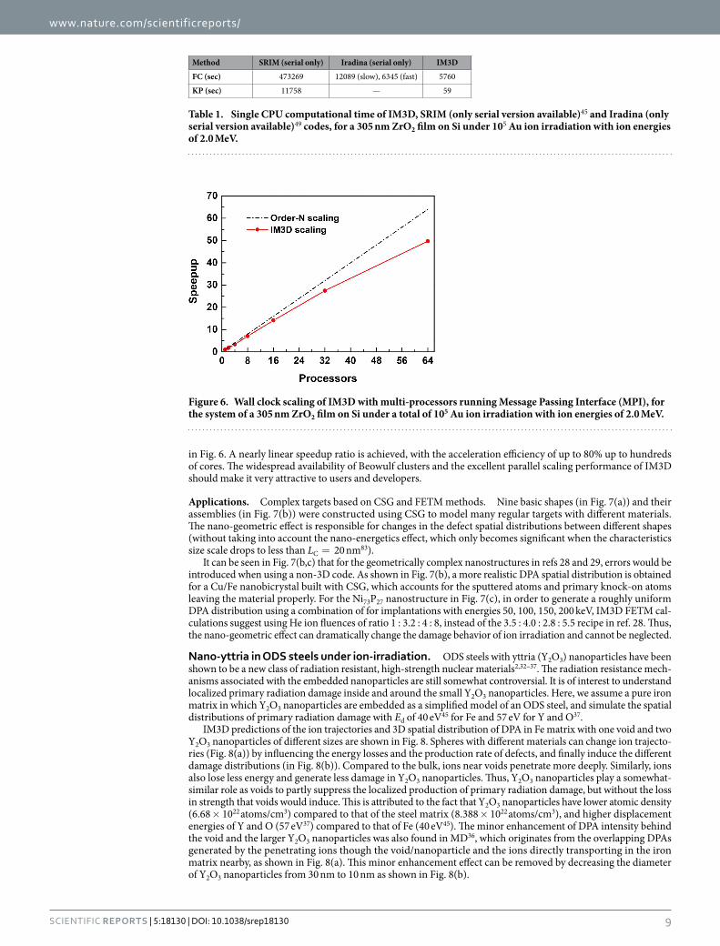
Benchmark of serial and parallel efficiency. As shown in Table 1, the single CPU core computational time of IM3D, SRIM45 and Iradina49 are given to showcase the high efficiency of IM3D serial version compared to the other MC codes, for a 305 nm ZrO2 film on Si under a total of 105 incoming Au ions with energy 2.0 MeV. In general, for 1D problems, IM3D in serial mode is faster than SRIM by at least two to three orders of magnitude, and a little faster than Iradina with the same indexing technique due to the fewer surfaces/interfaces between different domains in the simulation system.
In addition, the parallel speedup ratio of the parallel version of IM3D was tested on a Beowulf cluster, for the system of a 305 nm ZrO2 film on Si under a total of 105 Au ions irradiation with ion energies of 2.0 MeV, as shown
Figure 5. Comparison of the number of vacancies in a (a) 3 nm and (b) 4 nm-diameter GaN nanowire along with Ar ion energies predicted by IM3D, the analytical model based on SRIM, and MD simulations. The curves for the analytical model are artificially scaled to have the same area as those from MD simulations, since the absolute amount of damage cannot be estimated reliably from the results based on SRIM calculations30. IM3D-1 and IM3D-2 correspond to the bulk energy thresholds and half values of the bulk thresholds used in the simulations, respectively. (c) Separate and total accumulation of three different types of defects (vacancies, interstitials and sputtered atoms) along with Ar ion energies, for the 3 nm and 4 nm-diameter GaN nanowire under Ar ion irradiation at the edge and face of a GaN nanowire.
www.nature.com/scientificreports/
9Scientific RepoRts | 5:18130 | DOI: 10.1038/srep18130
in Fig. 6. A nearly linear speedup ratio is achieved, with the acceleration efficiency of up to 80% up to hundreds of cores. The widespread availability of Beowulf clusters and the excellent parallel scaling performance of IM3D should make it very attractive to users and developers.
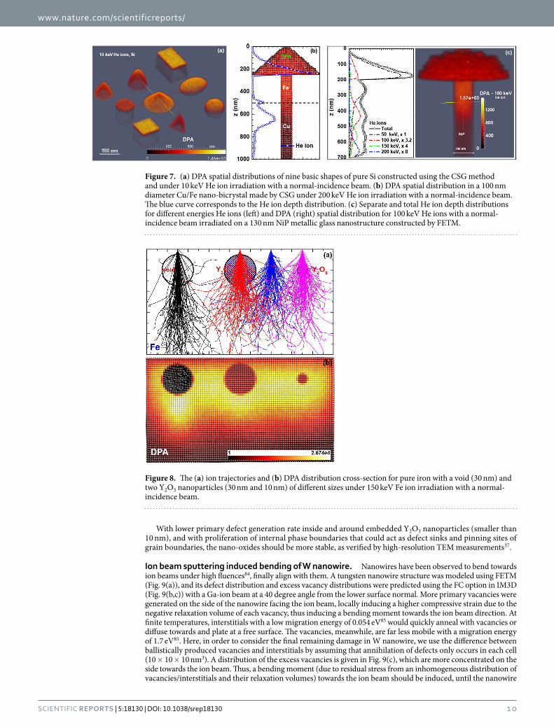
Applications. Complex targets based on CSG and FETM methods. Nine basic shapes (in Fig. 7(a)) and their assemblies (in Fig. 7(b)) were constructed using CSG to model many regular targets with different materials. The nano-geometric effect is responsible for changes in the defect spatial distributions between different shapes (without taking into account the nano-energetics effect, which only becomes significant when the characteristics size scale drops to less than LC = 20 nm83).
It can be seen in Fig. 7(b,c) that for the geometrically complex nanostructures in refs 28 and 29, errors would be introduced when using a non-3D code. As shown in Fig. 7(b), a more realistic DPA spatial distribution is obtained for a Cu/Fe nanobicrystal built with CSG, which accounts for the sputtered atoms and primary knock-on atoms leaving the material properly. For the Ni73P27 nanostructure in Fig. 7(c), in order to generate a roughly uniform DPA distribution using a combination of for implantations with energies 50, 100, 150, 200 keV, IM3D FETM cal-culations suggest using He ion fluences of ratio 1 : 3.2 : 4 : 8, instead of the 3.5 : 4.0 : 2.8 : 5.5 recipe in ref. 28. Thus, the nano-geometric effect can dramatically change the damage behavior of ion irradiation and cannot be neglected.
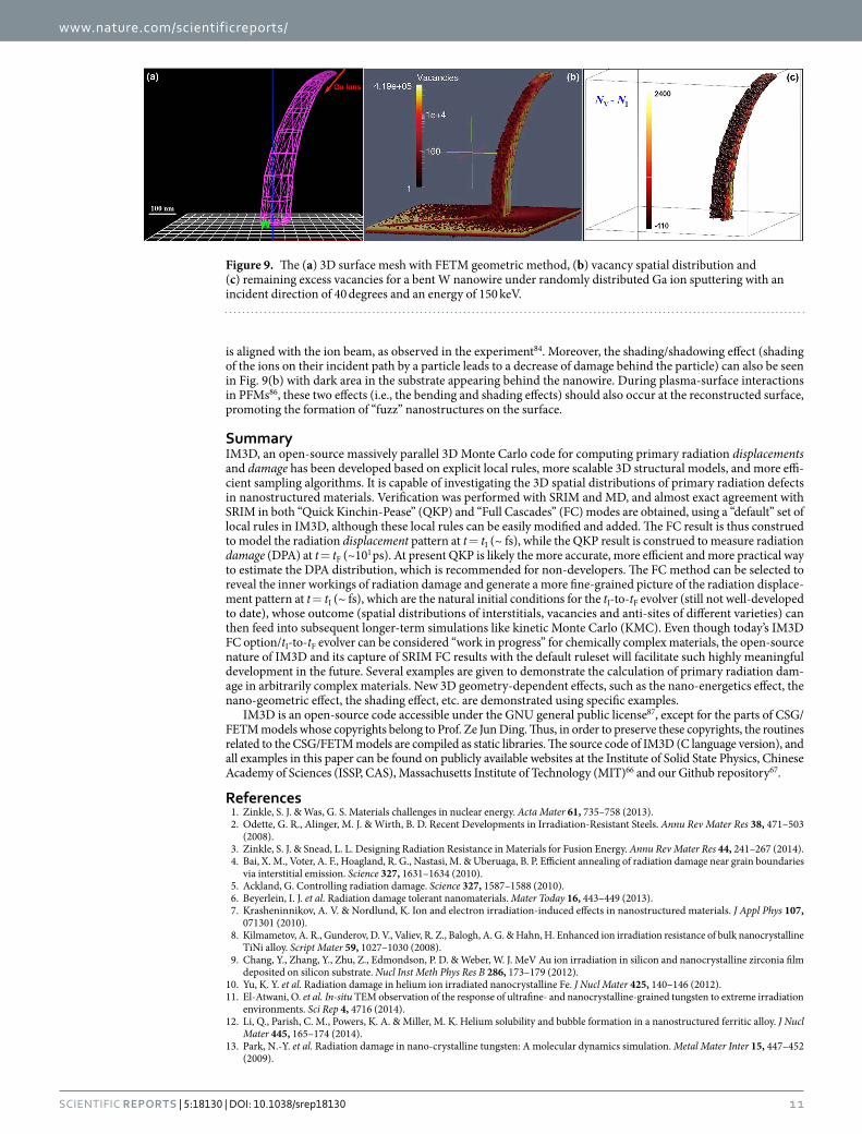
Nano-yttria in ODS steels under ion-irradiation. ODS steels with yttria (Y2O3) nanoparticles have been shown to be a new class of radiation resistant, high-strength nuclear materials2,32–37. The radiation resistance mech-anisms associated with the embedded nanoparticles are still somewhat controversial. It is of interest to understand localized primary radiation damage inside and around the small Y2O3 nanoparticles. Here, we assume a pure iron matrix in which Y2O3 nanoparticles are embedded as a simplified model of an ODS steel, and simulate the spatial distributions of primary radiation damage with Ed of 40 eV45 for Fe and 57 eV for Y and O37.
IM3D predictions of the ion trajectories and 3D spatial distribution of DPA in Fe matrix with one void and two Y2O3 nanoparticles of different sizes are shown in Fig. 8. Spheres with different materials can change ion trajecto-ries (Fig. 8(a)) by influencing the energy losses and the production rate of defects, and finally induce the different damage distributions (in Fig. 8(b)). Compared to the bulk, ions near voids penetrate more deeply. Similarly, ions also lose less energy and generate less damage in Y2O3 nanoparticles. Thus, Y2O3 nanoparticles play a somewhat-similar role as voids to partly suppress the localized production of primary radiation damage, but without the loss in strength that voids would induce. This is attributed to the fact that Y2O3 nanoparticles have lower atomic density (6.68 × 10²² atoms/cm3) compared to that of the steel matrix (8.388 × 10²² atoms/cm3), and higher displacement energies of Y and O (57 eV37) compared to that of Fe (40 eV45). The minor enhancement of DPA intensity behind the void and the larger Y2O3 nanoparticles was also found in MD36, which originates from the overlapping DPAs generated by the penetrating ions though the void/nanoparticle and the ions directly transporting in the iron matrix nearby, as shown in Fig. 8(a). This minor enhancement effect can be removed by decreasing the diameter of Y2O3 nanoparticles from 30 nm to 10 nm as shown in Fig. 8(b).
Method SRIM (serial only) Iradina (serial only) IM3D
FC (sec) 473269 12089 (slow), 6345 (fast) 5760
KP (sec) 11758 — 59
Table 1. Single CPU computational time of IM3D, SRIM (only serial version available)45 and Iradina (only serial version available)49 codes, for a 305 nm ZrO2 film on Si under 105 Au ion irradiation with ion energies of 2.0 MeV.
Figure 6. Wall clock scaling of IM3D with multi-processors running Message Passing Interface (MPI), for the system of a 305 nm ZrO2 film on Si under a total of 105 Au ion irradiation with ion energies of 2.0 MeV.
www.nature.com/scientificreports/
1 0Scientific RepoRts | 5:18130 | DOI: 10.1038/srep18130
With lower primary defect generation rate inside and around embedded Y2O3 nanoparticles (smaller than 10 nm), and with proliferation of internal phase boundaries that could act as defect sinks and pinning sites of grain boundaries, the nano-oxides should be more stable, as verified by high-resolution TEM measurements37.
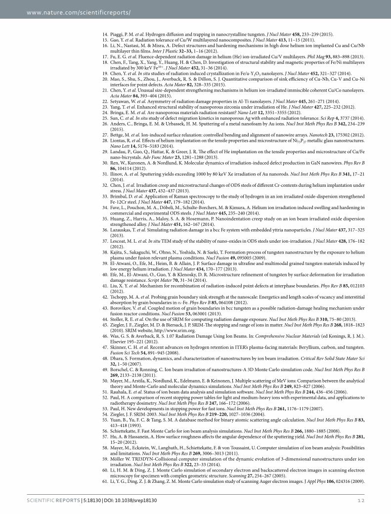
Ion beam sputtering induced bending of W nanowire. Nanowires have been observed to bend towards ion beams under high fluences84, finally align with them. A tungsten nanowire structure was modeled using FETM (Fig. 9(a)), and its defect distribution and excess vacancy distributions were predicted using the FC option in IM3D (Fig. 9(b,c)) with a Ga-ion beam at a 40 degree angle from the lower surface normal. More primary vacancies were generated on the side of the nanowire facing the ion beam, locally inducing a higher compressive strain due to the negative relaxation volume of each vacancy, thus inducing a bending moment towards the ion beam direction. At finite temperatures, interstitials with a low migration energy of 0.054 eV85 would quickly anneal with vacancies or diffuse towards and plate at a free surface. The vacancies, meanwhile, are far less mobile with a migration energy of 1.7 eV85. Here, in order to consider the final remaining damage in W nanowire, we use the difference between ballistically produced vacancies and interstitials by assuming that annihilation of defects only occurs in each cell (10 × 10 × 10 nm3). A distribution of the excess vacancies is given in Fig. 9(c), which are more concentrated on the side towards the ion beam. Thus, a bending moment (due to residual stress from an inhomogeneous distribution of vacancies/interstitials and their relaxation volumes) towards the ion beam should be induced, until the nanowire
Figure 7. (a) DPA spatial distributions of nine basic shapes of pure Si constructed using the CSG method and under 10 keV He ion irradiation with a normal-incidence beam. (b) DPA spatial distribution in a 100 nm diameter Cu/Fe nano-bicrystal made by CSG under 200 keV He ion irradiation with a normal-incidence beam. The blue curve corresponds to the He ion depth distribution. (c) Separate and total He ion depth distributions for different energies He ions (left) and DPA (right) spatial distribution for 100 keV He ions with a normal-incidence beam irradiated on a 130 nm NiP metallic glass nanostructure constructed by FETM.
Figure 8. The (a) ion trajectories and (b) DPA distribution cross-section for pure iron with a void (30 nm) and two Y2O3 nanoparticles (30 nm and 10 nm) of different sizes under 150 keV Fe ion irradiation with a normal-incidence beam.
www.nature.com/scientificreports/
1 1Scientific RepoRts | 5:18130 | DOI: 10.1038/srep18130
is aligned with the ion beam, as observed in the experiment84. Moreover, the shading/shadowing effect (shading of the ions on their incident path by a particle leads to a decrease of damage behind the particle) can also be seen in Fig. 9(b) with dark area in the substrate appearing behind the nanowire. During plasma-surface interactions in PFMs86, these two effects (i.e., the bending and shading effects) should also occur at the reconstructed surface, promoting the formation of “fuzz” nanostructures on the surface.
SummaryIM3D, an open-source massively parallel 3D Monte Carlo code for computing primary radiation displacements and damage has been developed based on explicit local rules, more scalable 3D structural models, and more effi-cient sampling algorithms. It is capable of investigating the 3D spatial distributions of primary radiation defects in nanostructured materials. Verification was performed with SRIM and MD, and almost exact agreement with SRIM in both “Quick Kinchin-Pease” (QKP) and “Full Cascades” (FC) modes are obtained, using a “default” set of local rules in IM3D, although these local rules can be easily modified and added. The FC result is thus construed to model the radiation displacement pattern at t = tI (~ fs), while the QKP result is construed to measure radiation damage (DPA) at t = tF (~101 ps). At present QKP is likely the more accurate, more efficient and more practical way to estimate the DPA distribution, which is recommended for non-developers. The FC method can be selected to reveal the inner workings of radiation damage and generate a more fine-grained picture of the radiation displace-ment pattern at t = tI (~ fs), which are the natural initial conditions for the tI-to-tF evolver (still not well-developed to date), whose outcome (spatial distributions of interstitials, vacancies and anti-sites of different varieties) can then feed into subsequent longer-term simulations like kinetic Monte Carlo (KMC). Even though today’s IM3D FC option/tI-to-tF evolver can be considered “work in progress” for chemically complex materials, the open-source nature of IM3D and its capture of SRIM FC results with the default ruleset will facilitate such highly meaningful development in the future. Several examples are given to demonstrate the calculation of primary radiation dam-age in arbitrarily complex materials. New 3D geometry-dependent effects, such as the nano-energetics effect, the nano-geometric effect, the shading effect, etc. are demonstrated using specific examples.
IM3D is an open-source code accessible under the GNU general public license87, except for the parts of CSG/FETM models whose copyrights belong to Prof. Ze Jun Ding. Thus, in order to preserve these copyrights, the routines related to the CSG/FETM models are compiled as static libraries. The source code of IM3D (C language version), and all examples in this paper can be found on publicly available websites at the Institute of Solid State Physics, Chinese Academy of Sciences (ISSP, CAS), Massachusetts Institute of Technology (MIT)66 and our Github repository67.
References1. Zinkle, S. J. & Was, G. S. Materials challenges in nuclear energy. Acta Mater 61, 735–758 (2013).2. Odette, G. R., Alinger, M. J. & Wirth, B. D. Recent Developments in Irradiation-Resistant Steels. Annu Rev Mater Res 38, 471–503
(2008).3. Zinkle, S. J. & Snead, L. L. Designing Radiation Resistance in Materials for Fusion Energy. Annu Rev Mater Res 44, 241–267 (2014).4. Bai, X. M., Voter, A. F., Hoagland, R. G., Nastasi, M. & Uberuaga, B. P. Efficient annealing of radiation damage near grain boundaries
via interstitial emission. Science 327, 1631–1634 (2010).5. Ackland, G. Controlling radiation damage. Science 327, 1587–1588 (2010).6. Beyerlein, I. J. et al. Radiation damage tolerant nanomaterials. Mater Today 16, 443–449 (2013).7. Krasheninnikov, A. V. & Nordlund, K. Ion and electron irradiation-induced effects in nanostructured materials. J Appl Phys 107,
071301 (2010).8. Kilmametov, A. R., Gunderov, D. V., Valiev, R. Z., Balogh, A. G. & Hahn, H. Enhanced ion irradiation resistance of bulk nanocrystalline
TiNi alloy. Script Mater 59, 1027–1030 (2008).9. Chang, Y., Zhang, Y., Zhu, Z., Edmondson, P. D. & Weber, W. J. MeV Au ion irradiation in silicon and nanocrystalline zirconia film
deposited on silicon substrate. Nucl Inst Meth Phys Res B 286, 173–179 (2012).10. Yu, K. Y. et al. Radiation damage in helium ion irradiated nanocrystalline Fe. J Nucl Mater 425, 140–146 (2012).11. El-Atwani, O. et al. In-situ TEM observation of the response of ultrafine- and nanocrystalline-grained tungsten to extreme irradiation
environments. Sci Rep 4, 4716 (2014).12. Li, Q., Parish, C. M., Powers, K. A. & Miller, M. K. Helium solubility and bubble formation in a nanostructured ferritic alloy. J Nucl
Mater 445, 165–174 (2014).13. Park, N.-Y. et al. Radiation damage in nano-crystalline tungsten: A molecular dynamics simulation. Metal Mater Inter 15, 447–452
(2009).
Figure 9. The (a) 3D surface mesh with FETM geometric method, (b) vacancy spatial distribution and (c) remaining excess vacancies for a bent W nanowire under randomly distributed Ga ion sputtering with an incident direction of 40 degrees and an energy of 150 keV.
www.nature.com/scientificreports/
1 2Scientific RepoRts | 5:18130 | DOI: 10.1038/srep18130
14. Piaggi, P. M. et al. Hydrogen diffusion and trapping in nanocrystalline tungsten. J Nucl Mater 458, 233–239 (2015).15. Gao, Y. et al. Radiation tolerance of Cu/W multilayered nanocomposites. J Nucl Mater 413, 11–15 (2011).16. Li, N., Nastasi, M. & Misra, A. Defect structures and hardening mechanisms in high dose helium ion implanted Cu and Cu/Nb
multilayer thin films. Inter J Plastic 32–33, 1–16 (2012).17. Fu, E. G. et al. Fluence-dependent radiation damage in helium (He) ion-irradiated Cu/V multilayers. Phil Mag 93, 883–898 (2013).18. Chen, F., Tang, X., Yang, Y., Huang, H. & Chen, D. Investigation of structural stability and magnetic properties of Fe/Ni multilayers
irradiated by 300 keV Fe10+. J Nucl Mater 452, 31–36 (2014).19. Chen, Y. et al. In situ studies of radiation induced crystallization in Fe/a-Y2O3 nanolayers. J Nucl Mater 452, 321–327 (2014).20. Mao, S., Shu, S., Zhou, J., Averback, R. S. & Dillon, S. J. Quantitative comparison of sink efficiency of Cu-Nb, Cu-V and Cu-Ni
interfaces for point defects. Acta Mater 82, 328–335 (2015).21. Chen, Y. et al. Unusual size-dependent strengthening mechanisms in helium ion-irradiated immiscible coherent Cu/Co nanolayers.
Acta Mater 84, 393–404 (2015).22. Setyawan, W. et al. Asymmetry of radiation damage properties in Al-Ti nanolayers. J Nucl Mater 445, 261–271 (2014).23. Yang, T. et al. Enhanced structural stability of nanoporous zirconia under irradiation of He. J Nucl Mater 427, 225–232 (2012).24. Bringa, E. M. et al. Are nanoporous materials radiation resistant? Nano Lett 12, 3351–3355 (2012).25. Sun, C. et al. In situ study of defect migration kinetics in nanoporous Ag with enhanced radiation tolerance. Sci Rep 4, 3737 (2014).26. Anders, C., Bringa, E. M. & Urbassek, H. M. Sputtering of a metal nanofoam by Au ions. Nucl Inst Meth Phys Res B 342, 234–239
(2015).27. Bettge, M. et al. Ion-induced surface relaxation: controlled bending and alignment of nanowire arrays. Nanotech 23, 175302 (2012).28. Liontas, R. et al. Effects of helium implantation on the tensile properties and microstructure of Ni73P27 metallic glass nanostructures.
Nano Lett 14, 5176–5183 (2014).29. Landau, P., Guo, Q., Hattar, K. & Greer, J. R. The effect of He implantation on the tensile properties and microstructure of Cu/Fe
nano-bicrystals. Adv Func Mater 23, 1281–1288 (2013).30. Ren, W., Kuronen, A. & Nordlund, K. Molecular dynamics of irradiation-induced defect production in GaN nanowires. Phys Rev B
86, 104114 (2012).31. Ilinov, A. et al. Sputtering yields exceeding 1000 by 80 keV Xe irradiation of Au nanorods. Nucl Inst Meth Phys Res B 341, 17–21
(2014).32. Chen, J. et al. Irradiation creep and microstructural changes of ODS steels of different Cr-contents during helium implantation under
stress. J Nucl Mater 437, 432–437 (2013).33. Brimbal, D. et al. Application of Raman spectroscopy to the study of hydrogen in an ion irradiated oxide-dispersion strengthened
Fe-12Cr steel. J Nucl Mater 447, 179–182 (2014).34. Fave, L., Pouchon, M. A., Döbeli, M., Schulte-Borchers, M. & Kimura, A. Helium ion irradiation induced swelling and hardening in
commercial and experimental ODS steels. J Nucl Mater 445, 235–240 (2014).35. Huang, Z., Harris, A., Maloy, S. A. & Hosemann, P. Nanoindentation creep study on an ion beam irradiated oxide dispersion
strengthened alloy. J Nucl Mater 451, 162–167 (2014).36. Lazauskas, T. et al. Simulating radiation damage in a bcc Fe system with embedded yttria nanoparticles. J Nucl Mater 437, 317–325
(2013).37. Lescoat, M. L. et al. In situ TEM study of the stability of nano-oxides in ODS steels under ion-irradiation. J Nucl Mater 428, 176–182
(2012).38. Kajita, S., Sakaguchi, W., Ohno, N., Yoshida, N. & Saeki, T. Formation process of tungsten nanostructure by the exposure to helium
plasma under fusion relevant plasma conditions. Nucl Fusion 49, 095005 (2009).39. El-Atwani, O., Efe, M., Heim, B. & Allain, J. P. Surface damage in ultrafine and multimodal grained tungsten materials induced by
low energy helium irradiation. J Nucl Mater 434, 170–177 (2013).40. Efe, M., El-Atwani, O., Guo, Y. & Klenosky, D. R. Microstructure refinement of tungsten by surface deformation for irradiation
damage resistance. Script Mater 70, 31–34 (2014).41. Liu, X. Y. et al. Mechanism for recombination of radiation-induced point defects at interphase boundaries. Phys Rev B 85, 012103
(2012).42. Tschopp, M. A. et al. Probing grain boundary sink strength at the nanoscale: Energetics and length scales of vacancy and interstitial
absorption by grain boundaries in α -Fe. Phys Rev B 85, 064108 (2012).43. Borovikov, V. et al. Coupled motion of grain boundaries in bcc tungsten as a possible radiation-damage healing mechanism under
fusion reactor conditions. Nucl Fusion 53, 063001 (2013).44. Stoller, R. E. et al. On the use of SRIM for computing radiation damage exposure. Nucl Inst Meth Phys Res B 310, 75–80 (2013).45. Ziegler, J. F., Ziegler, M. D. & Biersack, J. P. SRIM-The stopping and range of ions in matter. Nucl Inst Meth Phys Res B 268, 1818–1823
(2010). SRIM website, http://www.srim.org.46. Was, G. S. & Averback, R. S. 1.07 Radiation Damage Using Ion Beams. In: Comprehensive Nuclear Materials (ed Konings, R. J. M.).
Elsevier 195–221 (2012).47. Skinner, C. H. et al. Recent advances on hydrogen retention in ITER’s plasma-facing materials: Beryllium, carbon, and tungsten.
Fusion Sci Tech 54, 891–945 (2008).48. Dhara, S. Formation, dynamics, and characterization of nanostructures by ion beam irradiation. Critical Rev Solid State Mater Sci
32, 1–50 (2007).49. Borschel, C. & Ronning, C. Ion beam irradiation of nanostructures-A 3D Monte Carlo simulation code. Nucl Inst Meth Phys Res B
269, 2133–2138 (2011).50. Mayer, M., Arstila, K., Nordlund, K., Edelmann, E. & Keinonen, J. Multiple scattering of MeV ions: Comparison between the analytical
theory and Monte-Carlo and molecular dynamics simulations. Nucl Inst Meth Phys Res B 249, 823–827 (2006).51. Rauhala, E. et al. Status of ion beam data analysis and simulation software. Nucl Inst Meth Phys Res B 244, 436–456 (2006).52. Paul, H. A comparison of recent stopping power tables for light and medium-heavy ions with experimental data, and applications to
radiotherapy dosimetry. Nucl Inst Meth Phys Res B 247, 166–172 (2006).53. Paul, H. New developments in stopping power for fast ions. Nucl Inst Meth Phys Res B 261, 1176–1179 (2007).54. Ziegler, J. F. SRIM-2003. Nucl Inst Meth Phys Res B 219–220, 1027–1036 (2004).55. Yuan, B., Yu, F. C. & Tang, S. M. A database method for binary atomic scattering angle calculation. Nucl Inst Meth Phys Res B 83,
413–418 (1993).56. Schiettekatte, F. Fast Monte Carlo for ion beam analysis simulations. Nucl Inst Meth Phys Res B 266, 1880–1885 (2008).57. Hu, A. & Hassanein, A. How surface roughness affects the angular dependence of the sputtering yield. Nucl Inst Meth Phys Res B 281,
15–20 (2012).58. Mayer, M., Eckstein, W., Langhuth, H., Schiettekatte, F. & von Toussaint, U. Computer simulation of ion beam analysis: Possibilities
and limitations. Nucl Inst Meth Phys Res B 269, 3006–3013 (2011).59. Möller W. TRI3DYN-Collisional computer simulation of the dynamic evolution of 3-dimensional nanostructures under ion
irradiation. Nucl Inst Meth Phys Res B 322, 23–33 (2014).60. Li, H. M. & Ding, Z. J. Monte Carlo simulation of secondary electron and backscattered electron images in scanning electron
microscopy for specimen with complex geometric structure. Scanning 27, 254–267 (2005).61. Li, Y. G., Ding, Z. J. & Zhang, Z. M. Monte Carlo simulation study of scanning Auger electron images. J Appl Phys 106, 024316 (2009).
www.nature.com/scientificreports/
13Scientific RepoRts | 5:18130 | DOI: 10.1038/srep18130
62. Li, Y. G., Mao, S. F., Li, H. M., Xiao, S. M. & Ding, Z. J. Monte Carlo simulation study of scanning electron microscopy images of rough surfaces. J Appl Phys 104, 064901 (2008).
63. Zhang, P., Wang, H. Y., Li, Y. G., Mao, S. F. & Ding, Z. J. Monte Carlo simulation of secondary electron images for real sample structures in scanning electron microscopy. Scanning 34, 145–150 (2012).
64. Li, Y. G., Mao, S. F. & Ding, Z. J. Chapter 11. Monte Carlo simulation of SEM and SAM images. In: Applications of Monte Carlo method in science and engineering (eds Mark, S. & Mordechai, S.). InTech-Open Access Publisher 231–296 (2011).
65. Li, Y. G., Zhang, P. & Ding, Z. J. Monte Carlo simulation of CD-SEM images for linewidth and critical dimension metrology. Scanning 35, 127–139 (2013).
66. Li, Y. G. et al. IM3D: Irradiated Microstructures in 3D. (2015). IM3D website, http://theory.issp.ac.cn/IM3D and http://Li.mit.edu/im3d.67. Li. Y. G. et al. IM3D Github Repository. (2015). URL https://github.com/shortlab/IM3D.68. Li, J. AtomEye: an efficient atomistic configuration viewer. Modelling Simul Mater Sci Eng 11, 173–177 (2003). AtomEye wibsite,
http://li.mit.edu/Archive/Graphics/A/.69. Geuzaine, C. & Remacle, J.-F. Gmsh: a three-dimensional finite element mesh generator with built-in pre- and post-processing
facilities. Inter J Nume Meth Eng 79, 1309–1331 (2009). Gmsh website, http://geuz.org/gmsh/.70. Sandia Corporation & Kitware Inc. (2005-2008). Paraview: an open-source, multi-platform data analysis and visualization application.
Paraview Foundation for Data Analysis and Visualization, Albuquerque & New York, USA. URL http://www.paraview.org/.71. Biersack, J. P. & Haggmark, L. G. A Monte Carlo computer program for the transport of enegetic ions in amorphous targets. Nucl
Inst Meth 174, 257–269 (1980).72. Sommerfeld, A. Asymptotische integration der differentialgleichung des Thomas-Fermischen atoms. Z Phys 78, 283–309 (1948).73. Lenz, W. Über die anwendbarkeit der statistischen methoden auf ionengitter. Z F Physik 77, 713–722 (1932).74. Moliere, V. G. Theorie der Streuung schneller geladener Teilchen I Einzelstreuung am abgeschirmten Coulomb-Feld. Z Naturforschung
2a, 133–145 (1947).75. Bohr, N. The penetration of atomic particles through matter. Mat Fys Medd Dan Vid Selsk 18, 142–143 (1948).76. Bohr, N. The penetration of atomic particles through matter. Mat Fys Medd Dan Vid Selsk 18, 8 (1948).77. Chu, W. K. Calculation of energy straggling for protons and helium ions. Phys Rev A 13, 2057–2060 (1976).78. Yang, Q. W., O’Connor, J. & Wang, Z. L. Empirical formulae for energy loss straggling of ions in matter. Z. Nucl Inst Meth Phys Res B
61, 149–155 (1991).79. Bragg, W. H. & Kleeman R. On the alpha particles of radium, and their loss of range in passing through various atoms and molecules.
Phil Mag 10, 318–340 (1905).80. Kinchin, G. H. & Pease, R. S. The displacement of atoms in solids by radiation. Rep Prog Phys 18, 1–51 (1955).81. Norgett, M. J., Robinson, M. T. & Torrens, I. M. A proposed method of calculating displacement dose rates. Nucl Eng Des 33, 50–54
(1975).82. Jourdan, T. & Crocombette, J.-P. Rate theory cluster dynamics simulations including spatial correlations within displacement cascades.
Phys Rev B 86, 054113 (2012).83. Ouyang, G., Li, X. L., Tan, X. & Yang, G. W. Surface energy of nanowires. Nanotech 19, 045709 (2008).84. Cui, A. et al. Ion-beam-induced bending of freestanding amorphous nanowires: The importance of the substrate material and charging.
Appl Phys Lett 102, 213112 (2013).85. Wolfer, W. G., 1.01 Fundamental Properties of Defects in Metals. In: Comprehensive Nuclear Materials (ed Konings, R. J. M.). Elsevier
1–45 (2012).86. Wirth, B. D., Hammond, K. D., Krasheninnikov, S. I. & Maroudas, D. Challenges and opportunities of modeling plasma-surface
interactions in tungsten using high-performance computing. J Nucl Mater 463, 30–38 (2015).87. Free Software Foundation, Inc. (2007). GNU General Public License. GNU is a Free, Copyleft License for Software and Other Kinds
of Works. Boston, USA. URL http://www.gnu.org/licenses/gpl.html.
AcknowledgementsThis work was supported by the National Science Foundation of China under Grant Nos 11275229, 11475215 & NSAF U1230202, the key project of National Science Foundation of China under Grant No. 11534012, the Special Funds for Major State Basic Research Project of China (973) under Grant No. 2012CB933702, the Hefei Center for Physical Science and Technology under Grant No. 2012FXZY004, and Director Grants of CASHIPS. Part of the calculations were performed at the Center for Computational Science of CASHIPS, the ScGrid of Supercomputing Center, and the Computer Network Information Center of the Chinese Academy of Sciences. JL and YY acknowledge support by NSF DMR-1410636 and DMR-1120901. Computational time on the Extreme Science and Engineering Discovery Environment (XSEDE) under the grant number TG-DMR130038 is gratefully acknowledged. ZD acknowledges support by National Natural Science Foundation of China (Nos 11274288 & 11574289), Ministry of Education of China (No. 20123402110034) and “111” project (No. B07033).
Author ContributionsJ.L., M.S. and Z.Z. sponsored and conceived the project. Y.L. developed the code and carried out the calculations. Y.L., J.L., Y.Y., M.S. and Z.Z. discussed the results and wrote the manuscript. Z.D. and Y.L. provided the structural algorithms. All authors reviewed the manuscript.
Additional InformationCompeting financial interests: The authors declare no competing financial interests.How to cite this article: Li, Y.G. et al. IM3D: A parallel Monte Carlo code for efficient simulations of primary radiation displacements and damage in 3D geometry. Sci. Rep. 5, 18130; doi: 10.1038/srep18130 (2015).
This work is licensed under a Creative Commons Attribution 4.0 International License. The images or other third party material in this article are included in the article’s Creative Commons license,
unless indicated otherwise in the credit line; if the material is not included under the Creative Commons license, users will need to obtain permission from the license holder to reproduce the material. To view a copy of this license, visit http://creativecommons.org/licenses/by/4.0/
Related Documents