Conext™ Core XC Series Grid Tie Photovoltaic Inverter Planning and Installation Manual www.schneider-electric.com

IM201304 ConextCoreXCSeries Installation Manual (990-4613B Rev-C)
Dec 01, 2015
schneider pv
Welcome message from author
This document is posted to help you gain knowledge. Please leave a comment to let me know what you think about it! Share it to your friends and learn new things together.
Transcript

Conext™ Core XC Series Grid Tie Photovoltaic Inverter
Planning and Installation Manual
www.schneider-electric.com

Conext Core XC Series Grid Tie Photovoltaic Inverter
Planning and Installation Manual
www.schneider-electric.com

Copyright © 2013 Schneider Electric. All Rights Reserved.
All trademarks are owned by Schneider Electric Industries SAS or its affiliated companies.
Exclusion for Documentation
UNLESS SPECIFICALLY AGREED TO IN WRITING, SELLER
(A) MAKES NO WARRANTY AS TO THE ACCURACY, SUFFICIENCY, OR SUITABILITY OF ANY TECHNICAL OR OTHER INFORMATION PROVIDED IN ITS MANUALS OR OTHER DOCUMENTATION;
(B) ASSUMES NO RESPONSIBILITY OR LIABILITY FOR LOSSES, DAMAGES, COSTS, OR EXPENSES, WHETHER SPECIAL, DIRECT, INDIRECT, CONSEQUENTIAL, OR INCIDENTAL, WHICH MIGHT ARISE OUT OF THE USE OF SUCH INFORMATION. THE USE OF ANY SUCH INFORMATION WILL BE ENTIRELY AT THE USER’S RISK; AND
(C) REMINDS YOU THAT IF THIS MANUAL IS IN ANY LANGUAGE OTHER THAN ENGLISH, ALTHOUGH STEPS HAVE BEEN TAKEN TO MAINTAIN THE ACCURACY OF THE TRANSLATION, THE ACCURACY CANNOT BE GUARANTEED. APPROVED CONTENT IS CONTAINED WITHIN THE ENGLISH LANGUAGE VERSION WHICH IS POSTED AT WWW.SCHNEIDER-ELECTRIC.COM.
Document Number: 990-4613B Revision: Revision C Date: February 2013
Contact Information www.schneider-electric.com
For other country details please contact your local Schneider Electric Sales Representative or visit the Schneider Electric website at:http://www.schneider-electric.com/sites/corporate/en/support/operations/local-operations/local-operations.page
Information About Your SystemAs soon as you open your product, record the following information and be sure to keep your proof of purchase.
Serial Number _________________________________
Product Number _________________________________
Purchased From _________________________________
Purchase Date _________________________________
About This Manual
Audience
This manual is intended for use by qualified personnel installing a system involving Schneider Electric Conext Core XC Series Grid Tie Photovoltaic Inverters.
Qualified personnel have training, knowledge, and experience in:
• Installing electrical equipment and PV power systems (up to 1000 V).
• Applying all applicable installation codes.
• Analyzing and reducing the hazards involved in performing electrical work.
• Selecting and using Personal Protective Equipment (PPE).
Configuration, servicing, and maintenance must be performed by authorized service personnel only. Authorized service personnel meet the requirements for a qualified installer, plus they have received specific training from the manufacturer on servicing the Conext Core XC Series.
This manual does not contain information regarding servicing or de-energization for servicing. Authorized service personnel should refer to the Service Bulletin for Conext Core XC Series Inverter Lock-Out and Tag-Out Procedures (document number 993-0438) and the Conext Core XC Series Grid Tie Photovoltaic Inverter Commissioning and Configuration Manual (document number 990-9283).
Conventions Used
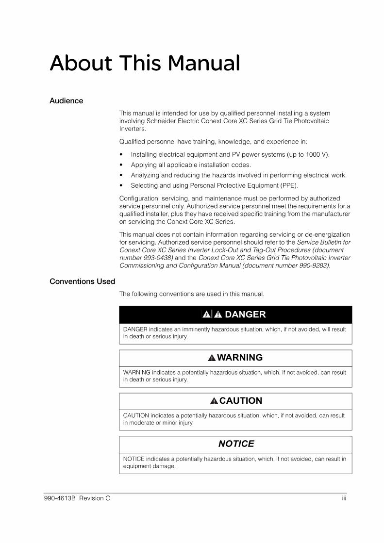
The following conventions are used in this manual.
DANGER
DANGER indicates an imminently hazardous situation, which, if not avoided, will result in death or serious injury.
WARNING
WARNING indicates a potentially hazardous situation, which, if not avoided, can result in death or serious injury.
CAUTION
CAUTION indicates a potentially hazardous situation, which, if not avoided, can result in moderate or minor injury.
NOTICE
NOTICE indicates a potentially hazardous situation, which, if not avoided, can result in equipment damage.
990-4613B Revision C iii
Conext Core XC Series Planning and Installation Manual
Abbreviations and Acronyms
Related Information
You can find more information about Schneider Electric and its products and services at www.schneider-electric.com.
AMCA Air Movement and Control Association International, Inc.
ANSI American National Standards Institute
BDEW Bundesverband der Energie- und Wasserwirtschaft German Association of Energy and Water Industries
CE European Conformity mark (European Union standards compliance)
CENELEC European committee for electrotechnical standardization
DIN Deutsches Institut für Normung (German national standards organization)
GFDI Ground fault detection interrupter
HVAC Heating, ventilation, and air-conditioning
IEC International Electrotechnical Commission
NFPA National Fire Protection Association
PE Protective earth (ground)
PPE Personal Protective Equipment
PV Photovoltaic
RMS Root mean square
SELV Safety Extra Low Voltage
VAC Volts (alternating current)
VDC Volts (direct current)
VDE Verband der Elektrotechnik, Elektronik und InformationstechnikGerman Association for Electrical, Electronic, and Information Technologies
iv 990-4613B Revision C

Important Safety Instructions
READ AND SAVE THESE INSTRUCTIONS - DO NOT DISCARD
This manual contains important safety instructions for the Conext Core XC Series Grid Tie Photovoltaic Inverter (Conext Core XC Series) that must be followed during installation procedures.
DANGER
HAZARD OF ELECTRIC SHOCK, FIRE, EXPLOSION, AND ARC FLASH
• Read all instructions, cautionary markings, and all other appropriate sections of this manual before installing or maintaining the Conext Core XC Series.
• To be installed and serviced only by qualified/authorized personnel equipped with appropriate personal protective equipment and following safe electrical work practices.
• This inverter is energized from multiple sources: the PV array, the AC grid, and the
external auxiliary AC source (if used). Before opening doorsa or covers:
– Consult system diagram to identify all sources.
– De-energize, lock out, and tag out all sources following the procedure beginning on page ix.
– Wait at least 15 minutes for internal capacitors to discharge to safe voltages.
• Operation of the switches in or on the inverter does not remove all power from this inverter. Switch terminals remain live unless the PV, AC, and external auxiliary AC source have been disconnected externally.
• Before servicing, test using a meter rated at least 1000 V AC and DC, to ensure all circuits are de-energized.
• For proper circuit isolation, connect a suitably rated isolating transformer between the output of the inverter and the utility power line connections. The transformer must be selected and installed in accordance with this manual. The transformer must be an isolation type having separate primary and secondary windings.
• This inverter must be mounted on a non-flammable surface. See “Anchoring the Inverter” on page 2–4 for details.
Failure to follow these instructions will result in death or serious injury.
a. A maintenance feature is available for equipped inverters that will allow the DC cabinet door tobe opened without interrupting inverter operation (opening any other doors will interrupt inverteroperation). Check with your country sales organization to determine whether your inverter isequipped with this feature.
990-4613B Revision C v

Conext Core XC Series Planning and Installation Manual
WARNING
HAZARD OF ELECTRIC SHOCK, EXPLOSION, FIRE, AND ARC FLASH HAZARD OF EQUIPMENT DAMAGE
Obey the manual’s instructions plus all physical, electrical, and environmental specifications shipped with the inverter.
Failure to follow these instructions can result in death or serious injury and/or damage to equipment.
WARNING
HAZARD OF ELECTRIC SHOCK, EXPLOSION, FIRE, AND ARC FLASH
• In all installations, the installer must provide external disconnecting means for the PV input, AC output, and external auxiliary AC source input wiring.
• The overcurrent protection devices within the inverter are intended to provide adequate protection for inverter circuitry only.
• It is the installer's responsibility to determine whether additional external overcurrent protection is required for the PV input, AC output, and external auxiliary AC source wiring, in accordance with the applicable installation codes.
Failure to follow these instructions can result in death or serious injury.
WARNING
HAZARD OF ELECTRIC SHOCK, EXPLOSION, FIRE, AND ARC FLASH
Do not install or attempt to operate the inverter if it has been dropped or has received more than cosmetic damage during transport or shipping. If the inverter is damaged, or suspected to be damaged, contact customer service.
Failure to follow these instructions can result in death or serious injury.
WARNING
LIMITATIONS ON USE
The inverter is not intended for use in connection with life support systems or other medical equipment or devices. The inverter can only be used in grid-interconnected PV systems. It is not suitable for any other application areas.
Failure to follow these instructions can result in death or serious injury.
WARNING
HAZARD OF CRUSH INJURY AND EQUIPMENT DAMAGE
• Use caution and follow the instructions in this manual for correct lifting, moving, and mounting of the inverter.
• The inverter can easily fall over if it is moved without caution. The inverter must be securely attached to the mounting surface after positioning.
Failure to follow these instructions can result in death or serious injury and/or damage to equipment.
vi 990-4613B Revision C

Safety
WARNING
HAZARD OF ELECTRIC SHOCK, EXPLOSION, AND ARC FLASH
Do not defeat or change the settings of the heaters located inside the inverter as these heaters are installed to help prevent condensation inside the inverter.
Failure to follow these instructions can result in death or serious injury and/or damage to equipment.
CAUTION
HAZARD OF BURNS
Components become hot during normal operation. Surfaces inside of the inverter may continue to be hot after the 15 minute duration required to discharge the internal capacitors. After opening the cabinet doors, follow all posted warnings and use caution before touching conductive surfaces.
Failure to follow these instructions can result in moderate or minor injury.
CAUTION
HAZARD OF OVERHEATING AND EQUIPMENT DAMAGE
• Keep the supply air and exhaust air areas unobstructed.
• Follow the installation, ventilation, and clearance instructions.
Failure to follow these instructions can result in moderate or minor injury and damage to equipment.
NOTICE
HAZARD OF EQUIPMENT DAMAGE
Inverter electronics can be destroyed by electrostatic charge. Wear electrostatic protection gear, and use anti-static tools and procedures when installing the inverter. Failure to follow these instructions can result in damage to equipment.
990-4613B Revision C vii

Conext Core XC Series Planning and Installation Manual
Personal Protection
Follow these instructions to help protect yourself while working with the Conext Core XC Series.
Installation personnel must be equipped with adequately rated, standard personal protective equipment including the following:
• Electrically rated protective gloves
• Protective glasses
• Fire resistant clothing
• Ear protection
• Electrically rated protection shoes or boots
• Electrical protection hard hat and face shield
• Padlocks and tags (for lock out and tag out of disconnects)
• Appropriately rated meter for verifying the inverter is de-energized
Check local safety regulations and applicable workplace safety procedures for additional requirements.
WARNING
HAZARD OF ELECTRIC SHOCK, EXPLOSION, AND ARC FLASH
• Never work alone when installing this inverter. A team of two is required until external sources are properly de-energized, locked out and tagged out, and verified de-energized with a meter, according to the procedure beginning on page ix.
• Thoroughly inspect the inverter prior to energizing. Verify that no tools or materials have inadvertently been left inside the inverter and that all guards and barriers are properly replaced and secured.
Failure to follow these instructions will result in death or serious injury.
viii 990-4613B Revision C
Safety
Installation Lock-out and Tag-out Procedure
Lock out refers to the practice of preventing de-energized circuits from being re-energized by putting locks on the disconnecting devices, holding them open. Tag out refers to the practice of attaching a tag to the disconnect-device locks warning others not to operate the disconnect device and containing information relating to the lock out, such as the person responsible, the reason, and the date and time. Combined these two practices are called the lock-out and tag-out (LOTO) procedure.
The installation LOTO procedure can only be used if the inverter is being energized for the first time, during installation. This procedure cannot be used once the inverter has been installed and energized for the first time.
If the inverter has been previously energized, additional steps are required to correctly LOTO the inverter for troubleshooting and service. These steps are detailed in the Service Bulletin for Conext Core XC Series Inverter Lock-Out and Tag-Out Procedures (document number 993-0438) and must be performed by authorized service personnel.
Follow all steps of this procedure to de-energize all sources of supply external to the inverter. This allows access to all parts of all cabinets, including behind internal barriers, during installation.
See Figure i and Figure iii for the locations of the parts of the inverter referred to in the following procedure.
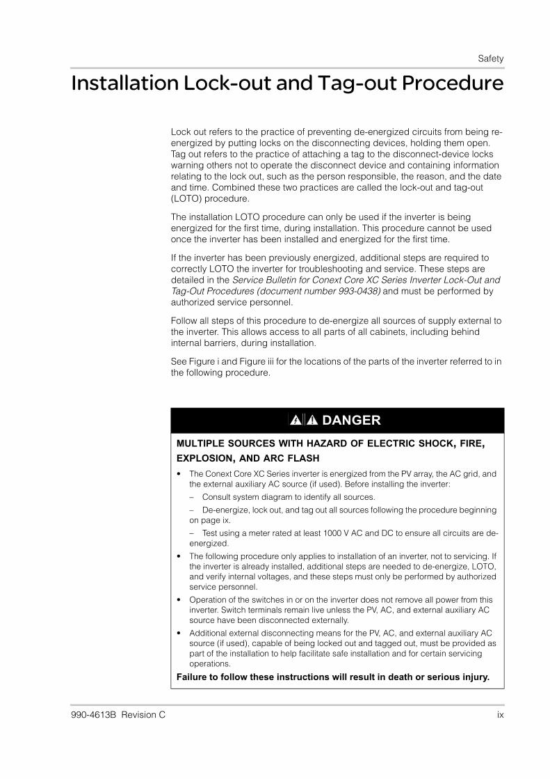
DANGER
MULTIPLE SOURCES WITH HAZARD OF ELECTRIC SHOCK, FIRE, EXPLOSION, AND ARC FLASH
• The Conext Core XC Series inverter is energized from the PV array, the AC grid, and the external auxiliary AC source (if used). Before installing the inverter:
– Consult system diagram to identify all sources.
– De-energize, lock out, and tag out all sources following the procedure beginning on page ix.
– Test using a meter rated at least 1000 V AC and DC to ensure all circuits are de-energized.
• The following procedure only applies to installation of an inverter, not to servicing. If the inverter is already installed, additional steps are needed to de-energize, LOTO, and verify internal voltages, and these steps must only be performed by authorized service personnel.
• Operation of the switches in or on the inverter does not remove all power from this inverter. Switch terminals remain live unless the PV, AC, and external auxiliary AC source have been disconnected externally.
• Additional external disconnecting means for the PV, AC, and external auxiliary AC source (if used), capable of being locked out and tagged out, must be provided as part of the installation to help facilitate safe installation and for certain servicing operations.
Failure to follow these instructions will result in death or serious injury.
990-4613B Revision C ix
Conext Core XC Series Planning and Installation Manual
Follow these lock-out and tag-out steps:
1. Turn the ENABLE STATE/DISABLE STATE switch to the DISABLE STATE position. See Figure i.
2. Turn the inverter ON/OFF switch to OFF. See Figure i.
3. Open, lock out, and tag out the AC output (grid) circuit at its external disconnecting means provided as part of the installation.
4. Open, lock out, and tag out all incoming PV input circuits at the external disconnecting means provided as part of the installation.
5. Open, lock out, and tag out the external auxiliary AC source (if used) at its external disconnecting means provided as part of the installation.
6. Wearing appropriate PPE and using a voltmeter with minimum ratings of 1000 V AC and DC that has been tested on a known AC voltage source and a known DC voltage source before use, verify that all external circuits are de-energized by checking for zero voltage at all of the following locations:
a) AC output (grid): Measure the voltage from each phase to ground and each phase to the other phases at the inverter side of the external disconnecting means provided as part of the installation.
b) PV input: Measure the voltage from DC+ and DC- to ground and from DC+ to DC- at the inverter side of the external disconnecting means provided as part of the installation.
c) External auxiliary AC source (if used): Measure the voltage from each phase to ground and from phase to phase at the inverter side of the external disconnecting means provided as part of the installation.
7. Open, lock out, and tag out the AC circuit breaker (QF1) on the AC cabinet door. See Figure i.
8. Open, lock out, and tag out the PV disconnect (QF11) on the DC cabinet door. See Figure i.
x 990-4613B Revision C
Safety
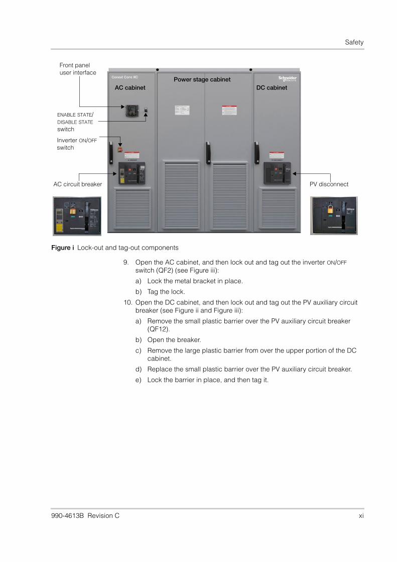
9. Open the AC cabinet, and then lock out and tag out the inverter ON/OFF switch (QF2) (see Figure iii):
a) Lock the metal bracket in place.
b) Tag the lock.
10. Open the DC cabinet, and then lock out and tag out the PV auxiliary circuit breaker (see Figure ii and Figure iii):
a) Remove the small plastic barrier over the PV auxiliary circuit breaker (QF12).
b) Open the breaker.
c) Remove the large plastic barrier from over the upper portion of the DC cabinet.
d) Replace the small plastic barrier over the PV auxiliary circuit breaker.
e) Lock the barrier in place, and then tag it.
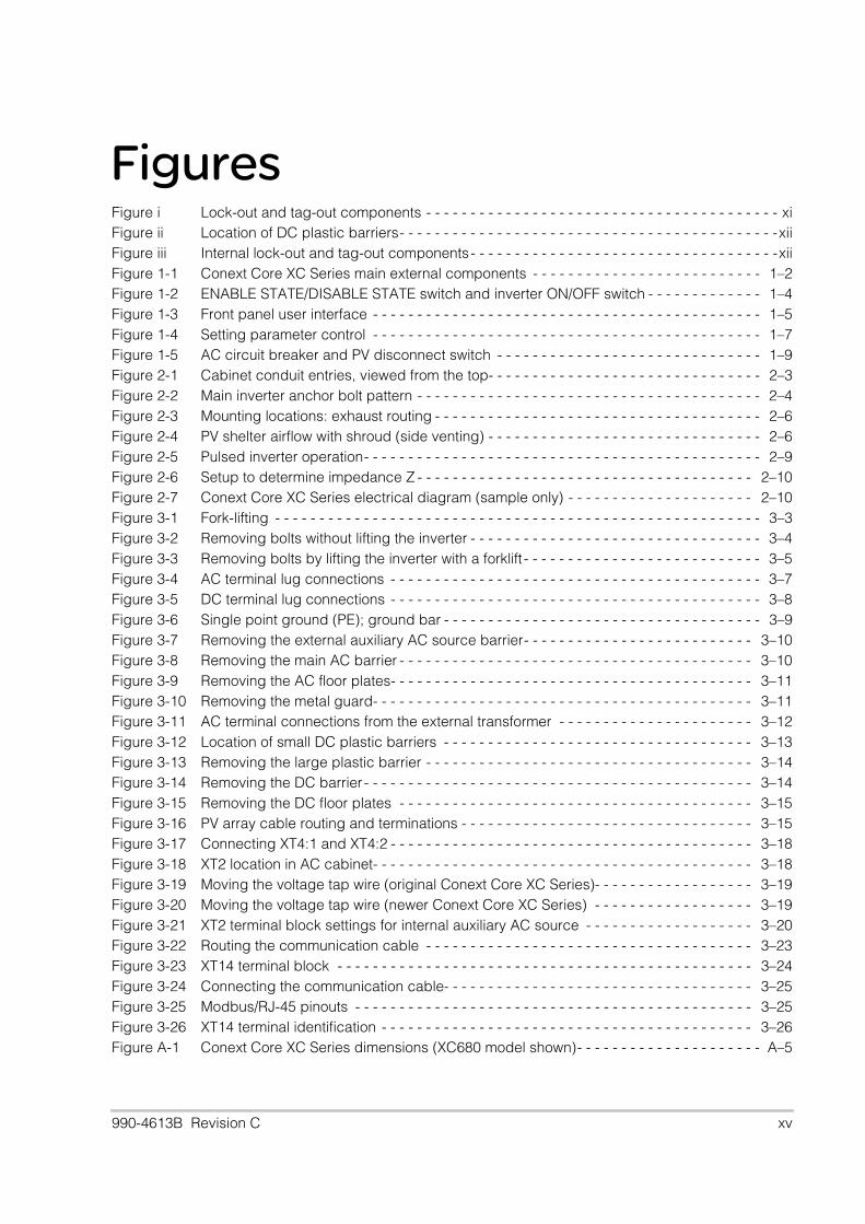
Figure i Lock-out and tag-out components
Power stage cabinetDC cabinet AC cabinet
ENABLE STATE/DISABLE STATE switch
Front panel user interface
Inverter ON/OFF switch
AC circuit breaker PV disconnect
990-4613B Revision C xi

Conext Core XC Series Planning and Installation Manual
When steps 1-10 have been completed:
• The external sources are verified de-energized, locked out, and tagged out.
• The inverter switches have all been opened, locked out, and tagged out.
This completes the LOTO procedure for the external sources and the inverter for first-time installation of the inverter.
Figure ii Location of DC plastic barriers
Remove these two screws to access the PV auxiliary circuit breaker.
Do not remove this screw. Do not remove the small plastic barrier over the surge arrestors.This barrier is only removed during maintenance to replace the surge protection devices.
Figure iii Internal lock-out and tag-out components
Internal inverter ON/OFF switch
PV auxiliary circuit breaker
Note: inverter shown with barriers removed
xii 990-4613B Revision C
Contents
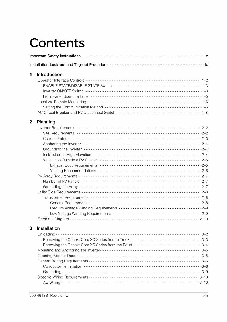
Important Safety Instructions - - - - - - - - - - - - - - - - - - - - - - - - - - - - - - - - - - - - - - - - - - - - - - - - vInstallation Lock-out and Tag-out Procedure - - - - - - - - - - - - - - - - - - - - - - - - - - - - - - - - - - - - - ix
1 IntroductionOperator Interface Controls - - - - - - - - - - - - - - - - - - - - - - - - - - - - - - - - - - - - - - - - - - - - - - - - - 1–2
ENABLE STATE/DISABLE STATE Switch - - - - - - - - - - - - - - - - - - - - - - - - - - - - - - - - - - - - - -1–3Inverter ON/OFF Switch - - - - - - - - - - - - - - - - - - - - - - - - - - - - - - - - - - - - - - - - - - - - - - - - - -1–3Front Panel User Interface - - - - - - - - - - - - - - - - - - - - - - - - - - - - - - - - - - - - - - - - - - - - - - - -1–5
Local vs. Remote Monitoring- - - - - - - - - - - - - - - - - - - - - - - - - - - - - - - - - - - - - - - - - - - - - - - - - 1–6Setting the Communication Method - - - - - - - - - - - - - - - - - - - - - - - - - - - - - - - - - - - - - - - - - -1–6
AC Circuit Breaker and PV Disconnect Switch - - - - - - - - - - - - - - - - - - - - - - - - - - - - - - - - - - - - 1–8
2 PlanningInverter Requirements - - - - - - - - - - - - - - - - - - - - - - - - - - - - - - - - - - - - - - - - - - - - - - - - - - - - - 2–2
Site Requirements - - - - - - - - - - - - - - - - - - - - - - - - - - - - - - - - - - - - - - - - - - - - - - - - - - - - - -2–2Conduit Entry - - - - - - - - - - - - - - - - - - - - - - - - - - - - - - - - - - - - - - - - - - - - - - - - - - - - - - - - - -2–3Anchoring the Inverter - - - - - - - - - - - - - - - - - - - - - - - - - - - - - - - - - - - - - - - - - - - - - - - - - - -2–4Grounding the Inverter - - - - - - - - - - - - - - - - - - - - - - - - - - - - - - - - - - - - - - - - - - - - - - - - - - -2–4Installation at High Elevation - - - - - - - - - - - - - - - - - - - - - - - - - - - - - - - - - - - - - - - - - - - - - - -2–4Ventilation Outside a PV Shelter - - - - - - - - - - - - - - - - - - - - - - - - - - - - - - - - - - - - - - - - - - - -2–5
Exhaust Duct Requirements - - - - - - - - - - - - - - - - - - - - - - - - - - - - - - - - - - - - - - - - - - - -2–5Venting Recommendations - - - - - - - - - - - - - - - - - - - - - - - - - - - - - - - - - - - - - - - - - - - - -2–6
PV Array Requirements - - - - - - - - - - - - - - - - - - - - - - - - - - - - - - - - - - - - - - - - - - - - - - - - - - - - 2–7Number of PV Panels - - - - - - - - - - - - - - - - - - - - - - - - - - - - - - - - - - - - - - - - - - - - - - - - - - - -2–7Grounding the Array - - - - - - - - - - - - - - - - - - - - - - - - - - - - - - - - - - - - - - - - - - - - - - - - - - - - -2–7
Utility Side Requirements - - - - - - - - - - - - - - - - - - - - - - - - - - - - - - - - - - - - - - - - - - - - - - - - - - - 2–8Transformer Requirements - - - - - - - - - - - - - - - - - - - - - - - - - - - - - - - - - - - - - - - - - - - - - - - -2–8
General Requirements - - - - - - - - - - - - - - - - - - - - - - - - - - - - - - - - - - - - - - - - - - - - - - - -2–8Medium Voltage Winding Requirements - - - - - - - - - - - - - - - - - - - - - - - - - - - - - - - - - - - -2–9Low Voltage Winding Requirements - - - - - - - - - - - - - - - - - - - - - - - - - - - - - - - - - - - - - -2–9
Electrical Diagram - - - - - - - - - - - - - - - - - - - - - - - - - - - - - - - - - - - - - - - - - - - - - - - - - - - - - - - 2–10
3 InstallationUnloading - - - - - - - - - - - - - - - - - - - - - - - - - - - - - - - - - - - - - - - - - - - - - - - - - - - - - - - - - - - - - - 3–2
Removing the Conext Core XC Series from a Truck - - - - - - - - - - - - - - - - - - - - - - - - - - - - - - -3–3Removing the Conext Core XC Series from the Pallet - - - - - - - - - - - - - - - - - - - - - - - - - - - - -3–4
Mounting and Anchoring the Inverter- - - - - - - - - - - - - - - - - - - - - - - - - - - - - - - - - - - - - - - - - - - 3–5Opening Access Doors - - - - - - - - - - - - - - - - - - - - - - - - - - - - - - - - - - - - - - - - - - - - - - - - - - - - 3–5General Wiring Requirements - - - - - - - - - - - - - - - - - - - - - - - - - - - - - - - - - - - - - - - - - - - - - - - - 3–6
Conductor Termination - - - - - - - - - - - - - - - - - - - - - - - - - - - - - - - - - - - - - - - - - - - - - - - - - - -3–6Grounding - - - - - - - - - - - - - - - - - - - - - - - - - - - - - - - - - - - - - - - - - - - - - - - - - - - - - - - - - - - -3–9
Specific Wiring Requirements - - - - - - - - - - - - - - - - - - - - - - - - - - - - - - - - - - - - - - - - - - - - - - - 3–10AC Wiring - - - - - - - - - - - - - - - - - - - - - - - - - - - - - - - - - - - - - - - - - - - - - - - - - - - - - - - - - - -3–10
990-4613B Revision C xiii
Conext Core XC Series Planning and Installation Manual
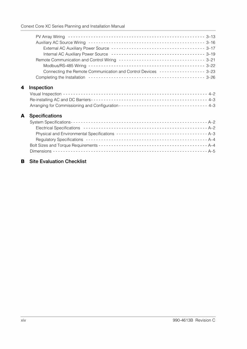
PV Array Wiring - - - - - - - - - - - - - - - - - - - - - - - - - - - - - - - - - - - - - - - - - - - - - - - - - - - - - - 3–13Auxiliary AC Source Wiring - - - - - - - - - - - - - - - - - - - - - - - - - - - - - - - - - - - - - - - - - - - - - - 3–16
External AC Auxiliary Power Source - - - - - - - - - - - - - - - - - - - - - - - - - - - - - - - - - - - - - 3–17Internal AC Auxiliary Power Source - - - - - - - - - - - - - - - - - - - - - - - - - - - - - - - - - - - - - 3–19
Remote Communication and Control Wiring - - - - - - - - - - - - - - - - - - - - - - - - - - - - - - - - - - 3–21Modbus/RS-485 Wiring - - - - - - - - - - - - - - - - - - - - - - - - - - - - - - - - - - - - - - - - - - - - - - 3–22Connecting the Remote Communication and Control Devices - - - - - - - - - - - - - - - - - - 3–23
Completing the Installation - - - - - - - - - - - - - - - - - - - - - - - - - - - - - - - - - - - - - - - - - - - - - - 3–26
4 InspectionVisual Inspection - - - - - - - - - - - - - - - - - - - - - - - - - - - - - - - - - - - - - - - - - - - - - - - - - - - - - - - - - 4–2Re-installing AC and DC Barriers - - - - - - - - - - - - - - - - - - - - - - - - - - - - - - - - - - - - - - - - - - - - - - 4–3Arranging for Commissioning and Configuration - - - - - - - - - - - - - - - - - - - - - - - - - - - - - - - - - - - 4–3
A SpecificationsSystem Specifications- - - - - - - - - - - - - - - - - - - - - - - - - - - - - - - - - - - - - - - - - - - - - - - - - - - - - - A–2
Electrical Specifications - - - - - - - - - - - - - - - - - - - - - - - - - - - - - - - - - - - - - - - - - - - - - - - - - A–2Physical and Environmental Specifications - - - - - - - - - - - - - - - - - - - - - - - - - - - - - - - - - - - - A–3Regulatory Specifications - - - - - - - - - - - - - - - - - - - - - - - - - - - - - - - - - - - - - - - - - - - - - - - - A–4
Bolt Sizes and Torque Requirements - - - - - - - - - - - - - - - - - - - - - - - - - - - - - - - - - - - - - - - - - - - A–4Dimensions - - - - - - - - - - - - - - - - - - - - - - - - - - - - - - - - - - - - - - - - - - - - - - - - - - - - - - - - - - - - - A–5
B Site Evaluation Checklist
xiv 990-4613B Revision C
Figures
Figure i Lock-out and tag-out components - - - - - - - - - - - - - - - - - - - - - - - - - - - - - - - - - - - - - - - - xiFigure ii Location of DC plastic barriers- - - - - - - - - - - - - - - - - - - - - - - - - - - - - - - - - - - - - - - - - - -xiiFigure iii Internal lock-out and tag-out components- - - - - - - - - - - - - - - - - - - - - - - - - - - - - - - - - - -xiiFigure 1-1 Conext Core XC Series main external components - - - - - - - - - - - - - - - - - - - - - - - - - - 1–2Figure 1-2 ENABLE STATE/DISABLE STATE switch and inverter ON/OFF switch - - - - - - - - - - - - - 1–4Figure 1-3 Front panel user interface - - - - - - - - - - - - - - - - - - - - - - - - - - - - - - - - - - - - - - - - - - - - 1–5Figure 1-4 Setting parameter control - - - - - - - - - - - - - - - - - - - - - - - - - - - - - - - - - - - - - - - - - - - - 1–7Figure 1-5 AC circuit breaker and PV disconnect switch - - - - - - - - - - - - - - - - - - - - - - - - - - - - - - 1–9Figure 2-1 Cabinet conduit entries, viewed from the top- - - - - - - - - - - - - - - - - - - - - - - - - - - - - - - 2–3Figure 2-2 Main inverter anchor bolt pattern - - - - - - - - - - - - - - - - - - - - - - - - - - - - - - - - - - - - - - - 2–4Figure 2-3 Mounting locations: exhaust routing - - - - - - - - - - - - - - - - - - - - - - - - - - - - - - - - - - - - - 2–6Figure 2-4 PV shelter airflow with shroud (side venting) - - - - - - - - - - - - - - - - - - - - - - - - - - - - - - - 2–6Figure 2-5 Pulsed inverter operation- - - - - - - - - - - - - - - - - - - - - - - - - - - - - - - - - - - - - - - - - - - - - 2–9Figure 2-6 Setup to determine impedance Z - - - - - - - - - - - - - - - - - - - - - - - - - - - - - - - - - - - - - - 2–10Figure 2-7 Conext Core XC Series electrical diagram (sample only) - - - - - - - - - - - - - - - - - - - - - 2–10Figure 3-1 Fork-lifting - - - - - - - - - - - - - - - - - - - - - - - - - - - - - - - - - - - - - - - - - - - - - - - - - - - - - - - 3–3Figure 3-2 Removing bolts without lifting the inverter - - - - - - - - - - - - - - - - - - - - - - - - - - - - - - - - - 3–4Figure 3-3 Removing bolts by lifting the inverter with a forklift - - - - - - - - - - - - - - - - - - - - - - - - - - - 3–5Figure 3-4 AC terminal lug connections - - - - - - - - - - - - - - - - - - - - - - - - - - - - - - - - - - - - - - - - - - 3–7Figure 3-5 DC terminal lug connections - - - - - - - - - - - - - - - - - - - - - - - - - - - - - - - - - - - - - - - - - - 3–8Figure 3-6 Single point ground (PE); ground bar - - - - - - - - - - - - - - - - - - - - - - - - - - - - - - - - - - - - 3–9Figure 3-7 Removing the external auxiliary AC source barrier- - - - - - - - - - - - - - - - - - - - - - - - - - 3–10Figure 3-8 Removing the main AC barrier - - - - - - - - - - - - - - - - - - - - - - - - - - - - - - - - - - - - - - - - 3–10Figure 3-9 Removing the AC floor plates- - - - - - - - - - - - - - - - - - - - - - - - - - - - - - - - - - - - - - - - - 3–11Figure 3-10 Removing the metal guard- - - - - - - - - - - - - - - - - - - - - - - - - - - - - - - - - - - - - - - - - - - 3–11Figure 3-11 AC terminal connections from the external transformer - - - - - - - - - - - - - - - - - - - - - - 3–12Figure 3-12 Location of small DC plastic barriers - - - - - - - - - - - - - - - - - - - - - - - - - - - - - - - - - - - 3–13Figure 3-13 Removing the large plastic barrier - - - - - - - - - - - - - - - - - - - - - - - - - - - - - - - - - - - - - 3–14Figure 3-14 Removing the DC barrier - - - - - - - - - - - - - - - - - - - - - - - - - - - - - - - - - - - - - - - - - - - - 3–14Figure 3-15 Removing the DC floor plates - - - - - - - - - - - - - - - - - - - - - - - - - - - - - - - - - - - - - - - - 3–15Figure 3-16 PV array cable routing and terminations - - - - - - - - - - - - - - - - - - - - - - - - - - - - - - - - - 3–15Figure 3-17 Connecting XT4:1 and XT4:2 - - - - - - - - - - - - - - - - - - - - - - - - - - - - - - - - - - - - - - - - - 3–18Figure 3-18 XT2 location in AC cabinet- - - - - - - - - - - - - - - - - - - - - - - - - - - - - - - - - - - - - - - - - - - 3–18Figure 3-19 Moving the voltage tap wire (original Conext Core XC Series)- - - - - - - - - - - - - - - - - - 3–19Figure 3-20 Moving the voltage tap wire (newer Conext Core XC Series) - - - - - - - - - - - - - - - - - - 3–19Figure 3-21 XT2 terminal block settings for internal auxiliary AC source - - - - - - - - - - - - - - - - - - - 3–20Figure 3-22 Routing the communication cable - - - - - - - - - - - - - - - - - - - - - - - - - - - - - - - - - - - - - 3–23Figure 3-23 XT14 terminal block - - - - - - - - - - - - - - - - - - - - - - - - - - - - - - - - - - - - - - - - - - - - - - - 3–24Figure 3-24 Connecting the communication cable- - - - - - - - - - - - - - - - - - - - - - - - - - - - - - - - - - - 3–25Figure 3-25 Modbus/RJ-45 pinouts - - - - - - - - - - - - - - - - - - - - - - - - - - - - - - - - - - - - - - - - - - - - - 3–25Figure 3-26 XT14 terminal identification - - - - - - - - - - - - - - - - - - - - - - - - - - - - - - - - - - - - - - - - - - 3–26Figure A-1 Conext Core XC Series dimensions (XC680 model shown)- - - - - - - - - - - - - - - - - - - - - A–5990-4613B Revision C xv

xvi
Tables
Table 1-1 Communication features - - - - - - - - - - - - - - - - - - - - - - - - - - - - - - - - - - - - - - - - - - - - - 1–6Table 3-1 Voltage ranges and transformer taps for external auxiliary AC source(original Conext Core XC Series) - - - - - - - - - - - - - - - - - - - - - - - - - - - - - - - - - - - - - - -3–17Table 3-2 Voltage ranges and transformer taps for external auxiliary AC source
(newer Conext Core XC Series) - - - - - - - - - - - - - - - - - - - - - - - - - - - - - - - - - - - - - - - -3–17Table 3-3 XT2:21 cable location for transformer tap
(original Conext Core XC Series) - - - - - - - - - - - - - - - - - - - - - - - - - - - - - - - - - - - - - - -3–19Table 3-4 Tap selection for internal auxiliary AC source connection
(original Conext Core XC Series) - - - - - - - - - - - - - - - - - - - - - - - - - - - - - - - - - - - - - - -3–20Table 3-5 Tap selection for internal auxiliary AC source connection
(newer Conext Core XC Series) - - - - - - - - - - - - - - - - - - - - - - - - - - - - - - - - - - - - - - - -3–20Table A-1 Electrical specifications- - - - - - - - - - - - - - - - - - - - - - - - - - - - - - - - - - - - - - - - - - - - - - A–2Table A-2 Physical and environmental specifications - - - - - - - - - - - - - - - - - - - - - - - - - - - - - - - - A–3Table A-3 AC terminal bolt size and torque values - - - - - - - - - - - - - - - - - - - - - - - - - - - - - - - - - - A–4Table A-4 PV terminal bolt size and torque values - - - - - - - - - - - - - - - - - - - - - - - - - - - - - - - - - - A–4
990-4613B Revision C xvii

xviii
1 Introduction
Chapter 1 contains information about the features and functions of the Conext Core XC Series.
990-4613B Revision C 1–1
Conext Core XC Series Planning and Installation Manual
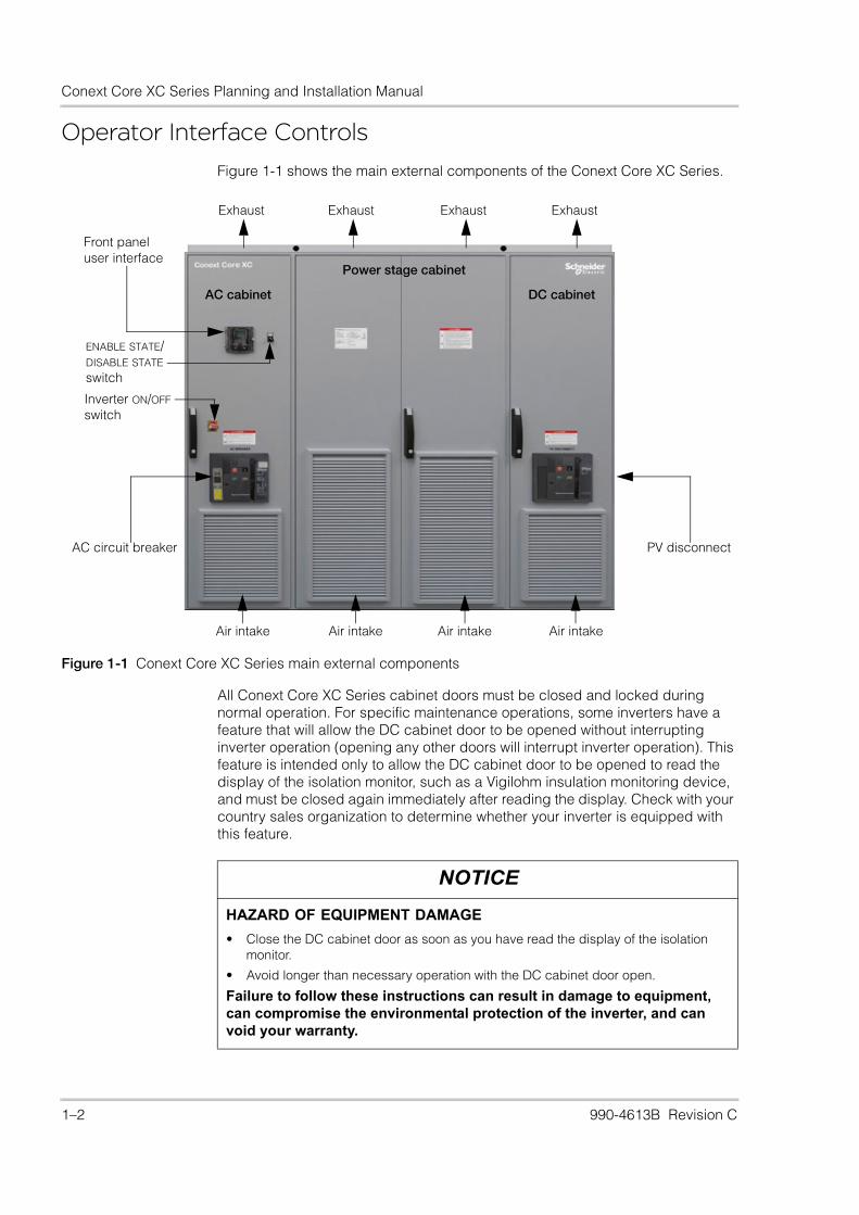
Operator Interface ControlsFigure 1-1 shows the main external components of the Conext Core XC Series.
All Conext Core XC Series cabinet doors must be closed and locked during normal operation. For specific maintenance operations, some inverters have a feature that will allow the DC cabinet door to be opened without interrupting inverter operation (opening any other doors will interrupt inverter operation). This feature is intended only to allow the DC cabinet door to be opened to read the display of the isolation monitor, such as a Vigilohm insulation monitoring device, and must be closed again immediately after reading the display. Check with your country sales organization to determine whether your inverter is equipped with this feature.
Figure 1-1 Conext Core XC Series main external components
Power stage cabinet
DC cabinet
Exhaust Exhaust Exhaust Exhaust
Air intakeAir intakeAir intakeAir intake
AC cabinet
ENABLE STATE/DISABLE STATE switch
Front panel user interface
Inverter ON/OFF switch
AC circuit breaker PV disconnect
NOTICE
HAZARD OF EQUIPMENT DAMAGE
• Close the DC cabinet door as soon as you have read the display of the isolation monitor.
• Avoid longer than necessary operation with the DC cabinet door open.
Failure to follow these instructions can result in damage to equipment, can compromise the environmental protection of the inverter, and can void your warranty.
1–2 990-4613B Revision C

Introduction: Operator Interface Controls
ENABLE STATE/DISABLE STATE Switch
The Conext Core XC Series has an ENABLE STATE/DISABLE STATE switch located on the AC cabinet door beside the front panel user interface, see Figure 1-2 on page 1–4.
Under normal conditions, the ENABLE STATE/DISABLE STATE switch is in the ENABLE STATE position. The main AC circuit breaker and PV disconnect switch will not close unless the switch is in the ENABLE STATE position. The inverter will not operate unless the switch is in the ENABLE STATE position.
To change any grid settings, the switch must be turned to the DISABLE STATE position. Turning the switch to the DISABLE STATE position initiates an immediate controlled shutdown of the inverter, and it opens both the main AC circuit breaker and PV disconnect switch within the inverter.
Inverter ON/OFF Switch
The Conext Core XC Series has an inverter ON/OFF switch located on the AC cabinet door, see Figure 1-2.
The inverter ON/OFF switch is also the auxiliary power breaker. Under normal conditions, the inverter ON/OFF switch is in the ON position, providing the auxiliary power necessary for power production and for maintenance functions such as viewing and extracting data from the front panel user interface or performing software updates. The main AC circuit breaker and PV disconnect switch cannot be closed unless the switch is in the ON position. The inverter will not restart unless the switch is in the ON position.
To initiate a power cycle, the switch must be turned to the OFF position and then back to the ON position. Turning the switch to the OFF position initiates an immediate controlled shutdown of the inverter and opens both the main AC circuit breaker and PV disconnect switch within the inverter.
DANGER
HAZARD OF ELECTRIC SHOCK, FIRE, EXPLOSION, AND ARC FLASH
Turning the switch to the DISABLE STATE position will not de-energize the inverter; it only stops power production. Externally disconnect the PV, AC, and external auxiliary AC source to de-energize the switch terminals.
Failure to follow these instructions will result in death or serious injury.
DANGER
HAZARD OF ELECTRIC SHOCK, FIRE, EXPLOSION, AND ARC FLASH
Turning the switch to the OFF position will not de-energize the inverter; it only stops power production. Externally disconnect the PV, AC, and external auxiliary AC source to de-energize the switch terminals.
Failure to follow these instructions will result in death or serious injury.
990-4613B Revision C 1–3

Conext Core XC Series Planning and Installation Manual
Figure 1-2 ENABLE STATE/DISABLE STATE switch and inverter ON/OFF switch
ENABLE STATE/DISABLE STATE switch
Inverter ON/OFF switch
1–4 990-4613B Revision C

Introduction: Operator Interface Controls
Front Panel User Interface
The Conext Core XC Series has a display and keypad with scroll wheel on the front panel for local monitoring and configuration (see Figure 1-3 on page 1–5). Extensive status information and Offline state or Service state events are reported to the front panel user interface. Use the scroll wheel to navigate through menu or value options, and press the center of the scroll wheel to select the menu or value. The keypad has four “F” function keys, RUN (remote enable) and STOP/RESET (remote disable) keys, and an ESC escape key.
See the Conext Core XC Series Grid Tie Photovoltaic Inverter Operation and Maintenance Manual (document number 990-4612) for additional details on how to operate the front panel user interface.
Figure 1-3 Front panel user interface
Inverter operating mode
Periodic servicingreminder
Inverter activity orstate description
Parameterdescription
F1 return to defaultparameter display
Event ID
Inverter state
Parameter value
F2, F3, and F4 function keys(context-specific)
Exit current menu
Inverter status line
Disable viasoftware command
Enable viasoftware command
Unused
Active Power Point Tracking
OnlineActive power
463.5 kW
Scroll wheel
PV LVL2 6341
Access level
!
990-4613B Revision C 1–5
Conext Core XC Series Planning and Installation Manual
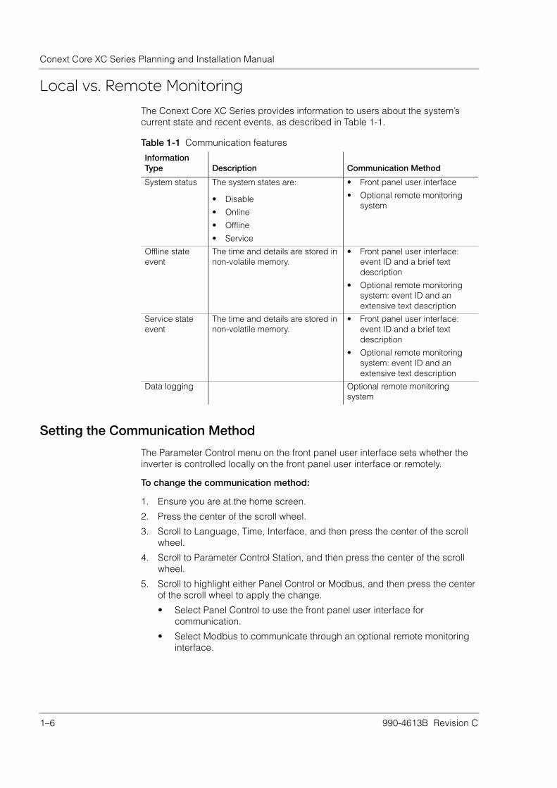
Local vs. Remote MonitoringThe Conext Core XC Series provides information to users about the system’s current state and recent events, as described in Table 1-1.
Setting the Communication Method
The Parameter Control menu on the front panel user interface sets whether the inverter is controlled locally on the front panel user interface or remotely.
To change the communication method:
1. Ensure you are at the home screen.
2. Press the center of the scroll wheel.
3. Scroll to Language, Time, Interface, and then press the center of the scroll wheel.
4. Scroll to Parameter Control Station, and then press the center of the scroll wheel.
5. Scroll to highlight either Panel Control or Modbus, and then press the center of the scroll wheel to apply the change.
• Select Panel Control to use the front panel user interface for communication.
• Select Modbus to communicate through an optional remote monitoring interface.
Table 1-1 Communication features
Information Type Description Communication Method
System status The system states are:
• Disable
• Online
• Offline
• Service
• Front panel user interface
• Optional remote monitoring system
Offline state event
The time and details are stored in non-volatile memory.
• Front panel user interface: event ID and a brief text description
• Optional remote monitoring system: event ID and an extensive text description
Service state event
The time and details are stored in non-volatile memory.
• Front panel user interface: event ID and a brief text description
• Optional remote monitoring system: event ID and an extensive text description
Data logging Optional remote monitoring system
1–6 990-4613B Revision C
Introduction: Local vs. Remote Monitoring
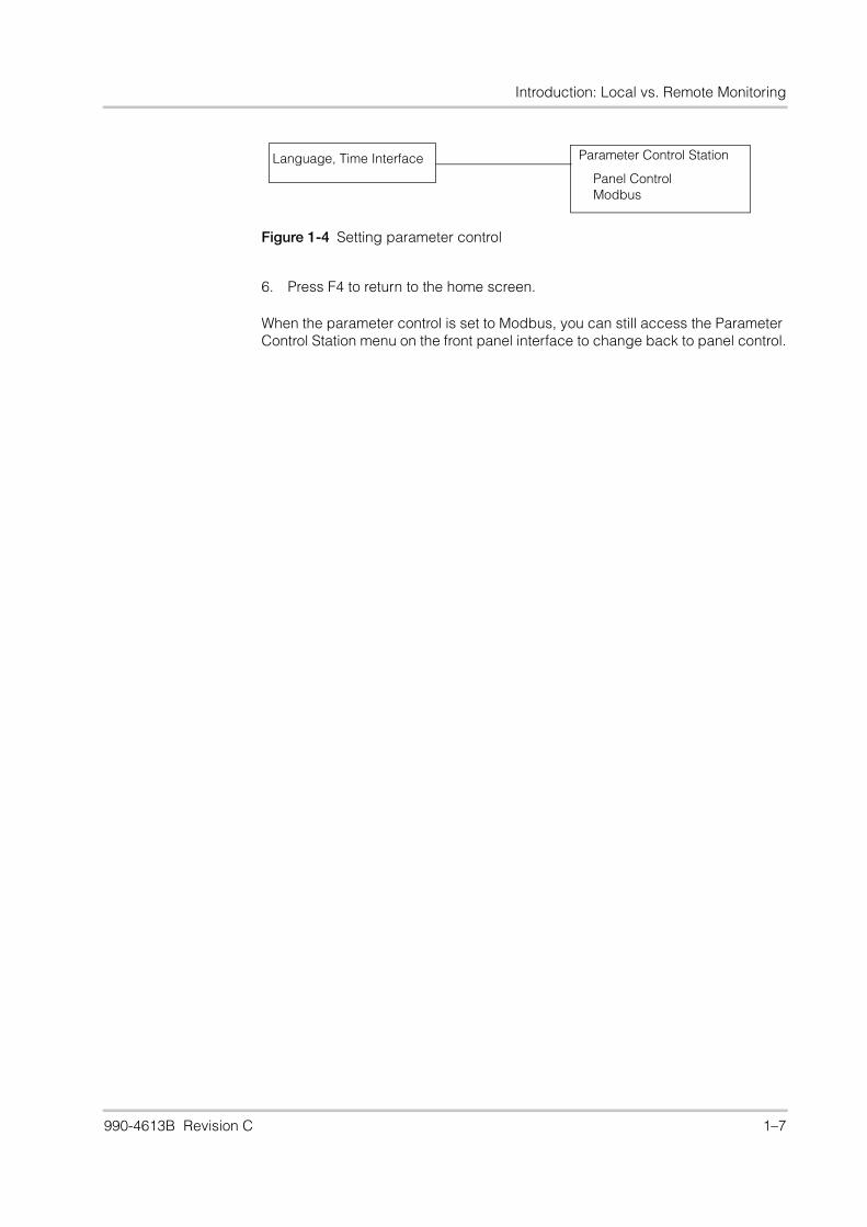
6. Press F4 to return to the home screen.
When the parameter control is set to Modbus, you can still access the Parameter Control Station menu on the front panel interface to change back to panel control.
Figure 1-4 Setting parameter control
Language, Time Interface Parameter Control Station
Panel ControlModbus
990-4613B Revision C 1–7
Conext Core XC Series Planning and Installation Manual
AC Circuit Breaker and PV Disconnect Switch
The main AC circuit breaker is located on the AC cabinet door and the PV disconnect switch is located on the DC cabinet door as shown in Figure 1-5 on page 1–9. Additional external AC and PV disconnecting means, capable of being locked out and tagged out, must be provided as part of the installation to help facilitate safe installation of the inverter and for certain service operations.
The main AC circuit breaker and PV disconnect switch are each load-break rated disconnects. During an Offline state or Service state event—or if the inverter is shut off for any reason—the AC circuit breaker and PV disconnect switch automatically open. Each is capable of breaking its full load current.
DANGER
MULTIPLE SOURCES WITH HAZARD OF ELECTRIC SHOCK, FIRE, EXPLOSION, AND ARC FLASH
• Operation of the switches in or on the inverter does not remove all power from this inverter. Switch terminals remain live unless the PV, AC, and external auxiliary AC source have been disconnected externally.
• All service and maintenance must be performed by authorized service personnel only, as defined on page iii, following the instructions in Service Bulletin for Conext Core XC Series Inverter Lock-Out and Tag-Out Procedures (document number 993-0438).
Failure to follow these instructions will result in death or serious injury.
1–8 990-4613B Revision C

Introduction: AC Circuit Breaker and PV Disconnect Switch
Figure 1-5 AC circuit breaker and PV disconnect switch
AC circuit breaker (QF1)
AC cabinet
PV disconnect switch (QF11)
DC cabinet
AC circuit breaker PV disconnect switch
990-4613B Revision C 1–9

Conext Core XC Series Planning and Installation Manual
1–10 990-4613B Revision C
2 Planning
DANGER
HAZARD OF ELECTRIC SHOCK, EXPLOSION, ARC FLASH, AND FIRE
• Installation of this inverter must only be planned and performed by qualified personnel in accordance with all applicable installation codes. See page iii for the definition of qualified personnel.
• The Conext Core XC Series must be mounted over a non-flammable surface in accordance with the instructions in “Inverter Requirements” below.
Failure to follow these instructions will result in death or serious injury.
990-4613B Revision C 2–1

Conext Core XC Series Planning and Installation Manual
Inverter Requirements
Site Requirements
The Conext Core XC Series is designed to be installed indoors only.
Establish and maintain the following site conditions to help facilitate safe and efficient installation, operation, and servicing of the Conext Core XC Series.
Ventilation The inverter has open sections in the bottom of the AC and DC cabinets and ventilation openings in the front of all cabinets. Additionally, there are exhaust openings at the top of all cabinets. Overall pressure drop across combined intake and exhaust must not exceed 60 Pa.
Flammability To help reduce the risk of fire, the inverter must be mounted over non-flammable surfaces below the inverter and extending in front of the inverter for 1 m (39½ in.). That area under and in front of the inverter must also be kept clear of flammable materials during operation of the inverter. The inverter must be mounted flush to the mounting surface, without openings around the bottom perimeter of the inverter. Openings for wire entry must be filled or closed to maintain a non-flammable barrier under the inverter.
Clearance Maintain a minimum clearance of 1 m (39½ in.) in front of the inverter—or more if required by local codes for service clearance—for air intake, maintenance, and serviceability. Maintain a minimum of 300 mm (11¾ in.) clearance above the inverter. Exhaust ducting must be installed in accordance with these requirements.
Accessibility Make sure the site is fork-lift accessible. A customer-supplied fork-lift and licensed fork-lift operator are required to perform many maintenance tasks.
Cabling External cabling enters the inverter from the bottom into the wiring compartments of the AC and DC cabinets. Appropriate conduits and fittings must be used based on local electrical codes.
IP rating The inverter has an ingress protection rating of IP20. The installation location must meet the physical and environmental specifications listed in Table A-2 on page A–3.
Heat load The heat load of the inverter is approximately 17 kW (58,000 BTU/hour) at full load. External ventilation or air conditioning must be designed to keep the ambient air outside of the inverter cabinets to a maximum of 45 °C (113 °F) to allow for full-rated inverter output power. Above 45 °C (113 °F), the inverter will derate its power output up to 50 °C (122 °F). Consult with Schneider Electric on derating charts for power output depending on ambient temperature.
The total cooling air flow required for the inverter is 4000 m³/h (3000 m³/h from the power stage cabinet and 500 m³/h each from the AC and DC cabinets).
Air intake quality The intake for the inverter is located on the front (see Figure 2-4). The intake airflow should meet the requirements of the environmental specifications listed in Table A-2 on page A–3. If these conditions cannot be met, filtration must be implemented external to the intake to ensure contaminants do not enter the inverter.
2–2 990-4613B Revision C

Planning: Inverter Requirements
Conduit Entry
Conduit and cable entry is from the bottom of the inverter. Figure 2-1 shows a top view of the maximum allowable area and location in which electrical conduits can penetrate the cabinets of the Conext Core XC Series. Conductor size must be pre-determined when the conduit is installed and must be based on local code requirements.
DANGER
HAZARD OF ELECTRIC SHOCK
• The circuits provided for use with external communications and control equipment are designed to provide safety isolation from neighboring hazardous circuits within the inverter. Separate conduit entries must be provided for the communications and control circuits and the PV circuits and all AC circuits. See “Remote Communication and Control Wiring” in the Conext Core XC Series Planning and Installation Manual for proper maintenance of safety isolation for wiring related to these circuits.
• The Conext Core XC Series is not provided with a conduit mounting surface to interface with the chassis. As such, no bonding to ground is provided for external metal conduits and this bonding must be provided elsewhere in the installation.
Failure to follow these instructions will result in death or serious injury.
Figure 2-1 Cabinet conduit entries, viewed from the top
Dimensions in mm(not to scale)
990-4613B Revision C 2–3
Conext Core XC Series Planning and Installation Manual
Anchoring the Inverter
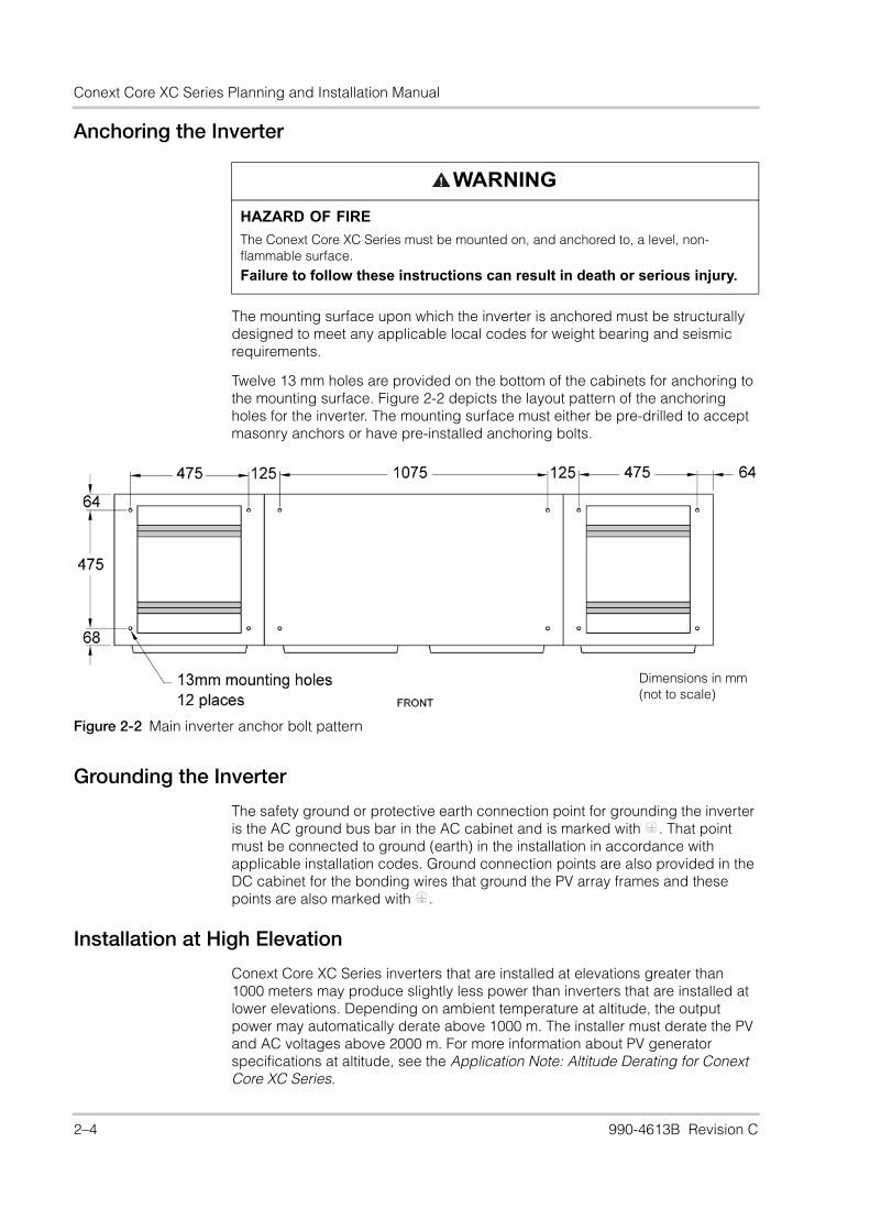
The mounting surface upon which the inverter is anchored must be structurally designed to meet any applicable local codes for weight bearing and seismic requirements.
Twelve 13 mm holes are provided on the bottom of the cabinets for anchoring to the mounting surface. Figure 2-2 depicts the layout pattern of the anchoring holes for the inverter. The mounting surface must either be pre-drilled to accept masonry anchors or have pre-installed anchoring bolts.
Grounding the Inverter
The safety ground or protective earth connection point for grounding the inverter is the AC ground bus bar in the AC cabinet and is marked with . That point must be connected to ground (earth) in the installation in accordance with applicable installation codes. Ground connection points are also provided in the DC cabinet for the bonding wires that ground the PV array frames and these points are also marked with .
Installation at High Elevation
Conext Core XC Series inverters that are installed at elevations greater than 1000 meters may produce slightly less power than inverters that are installed at lower elevations. Depending on ambient temperature at altitude, the output power may automatically derate above 1000 m. The installer must derate the PV and AC voltages above 2000 m. For more information about PV generator specifications at altitude, see the Application Note: Altitude Derating for Conext Core XC Series.
WARNING
HAZARD OF FIRE
The Conext Core XC Series must be mounted on, and anchored to, a level, non-flammable surface.
Failure to follow these instructions can result in death or serious injury.
Figure 2-2 Main inverter anchor bolt pattern
Dimensions in mm(not to scale)
2–4 990-4613B Revision C
Planning: Inverter Requirements
Ventilation Outside a PV Shelter
Conext Core XC Series inverters can be installed in a PV shelter designed typically to house inverters, distribution boxes, transformers, and monitoring equipment. Schneider Electric sells PV shelters, under the product name PV Boxes.
The ventilation required when using a PV shelter must meet the following criteria:
• Wind, including lateral wind, must not be allowed to stop outgoing air flow while the inverter is operating.
• Predict any way that wind, including lateral wind, may compromise the venting method used, such as partially closing vents, or closing all of the vents on one side of the PV shelter. The result of this compromise must not exceed the allowable overall pressure drop (see “Ventilation” on page 2–2) and must maintain the minimum airflow requirements of the inverter (see “Heat load” on page 2–2).
• Wind, including lateral wind, must not be allowed to create a back-flow of air (carrying humidity, snow, rain, or dust) into the inverter at any time.
You may use a single component, such as an actuated damper, or a combination of components, such as a duct, shroud, and louvers, to meet the criteria.
Exhaust Duct Requirements
A standard HVAC sheet metal duct can be integrated and sealed to the interior wall of the PV shelter to make sure exhaust airflow cannot recirculate within the PV shelter. One 90° bend with a smooth transition is permitted as shown in Figure 2-4 on page 2–6. The duct must be designed to accommodate the following:
• Minimum duct area: 445 x 2250 mm (17.5 x 88.5 in.).
• Overall pressure drop across combined intake and exhaust for the PV shelter must not exceed 60 Pa.
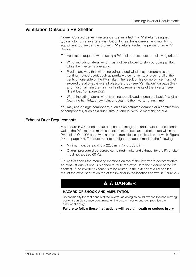
Figure 2-3 shows the mounting locations on top of the inverter to accommodate an exhaust duct (if one is planned to route the exhaust to the exterior of the PV shelter). If the inverter exhaust is to be routed to the exterior of a PV shelter, mount the exhaust duct on top of the inverter in the locations shown in Figure 2-3.
DANGER
HAZARD OF SHOCK AND AMPUTATION
Do not modify the roof panels of the inverter as doing so could expose live and moving parts. It can also cause contamination inside the inverter and compromise the functional design.
Failure to follow these instructions will result in death or serious injury.
990-4613B Revision C 2–5

Conext Core XC Series Planning and Installation Manual
Venting Recommendations
You can use any configuration that meets the requirements in “Ventilation Outside a PV Shelter” on page 2–5. One recommended venting configuration is:
• Side venting with fixed and gravity louvers and a shroud (see Figure 2-4).
Figure 2-3 Mounting locations: exhaust routing
The minimum duct area to prevent airflow restriction is 445 x 2250 mm (17½ x 88½ in.).
Figure 2-4 PV shelter airflow with shroud (side venting)
Gravity louvers
Intake airflow
Shroud
Duct
Grey arrows show exhaust airflow
Fixed louvers
2–6 990-4613B Revision C
Planning: PV Array Requirements
PV Array RequirementsIn all installations, the installer must provide disconnecting means for the PV input. The installer is also responsible for determining any external overcurrent protection required for these circuits, in accordance with the applicable installation codes, the currents involved (see Appendix A, “Specifications”), the wiring size used, and any other system parameters required by the installation codes.
Number of PV Panels
To determine the number of photovoltaic panels required for the PV power plant, use the PV planning tool or sizing tool on the Schneider Electric website (www.schneider-electric.com).
Grounding the Array
The PV input can be floating, positive grounded, or negative grounded, depending on the options ordered.
For positive grounded or negative grounded arrays, a factory-installed PV grounding option provides positive or negative grounding of the array, depending on the version ordered, and it includes a 10 A ground fault detector/interrupter (GFDI). This circuit breaker will open the array grounding path to interrupt ground fault currents exceeding the trip levels of the breaker. At the same time, it will shut down the inverter, open the AC breaker and PV disconnect, and report an event with the appropriate event ID to the front panel user interface and to any optional remote monitoring system.
For floating arrays, an optional factory-installed PV isolation monitoring relay is available that will monitor the array insulation resistance to ground. If the array insulation resistance falls below the setpoint, the isolation monitor will shut down the inverter, open the AC breaker and PV disconnect, and report an event with the appropriate event ID to the front panel user interface and to any optional remote monitoring system.
The qualified installer is responsible for determining the type and settings of ground fault protection that will provide adequate protection for the array and its wiring and that are acceptable according to applicable local codes and standards.
990-4613B Revision C 2–7
Conext Core XC Series Planning and Installation Manual
Utility Side RequirementsIn all installations, the installer must provide disconnecting means for the AC input and external auxiliary AC source input wiring. The installer is also responsible for determining any external overcurrent protection required for these circuits, in accordance with the applicable installation codes, the currents involved (see Appendix A, “Specifications”), the wiring size used, and any other system parameters required by the installation codes.
Transformer Requirements
A custom, high-efficiency, line-frequency isolation transformer must be placed between the inverter and the grid. This transformer is not provided and must be supplied as a separate component.
General Requirements
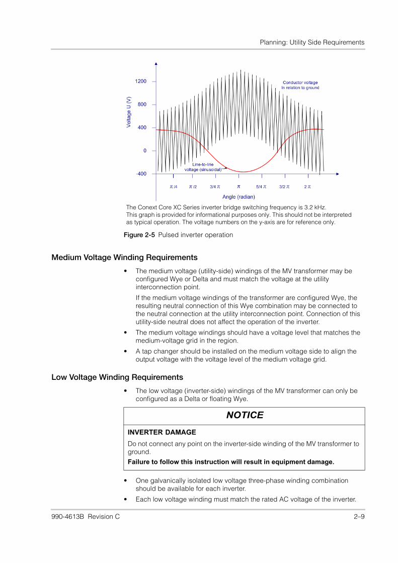
• The MV transformer must be capable of handling non-sinusoidal voltages up to 450 V of ground. These voltages may occur due to pulsed inverter operation as illustrated in Figure 2-5 on page 2–9.
• The rms (root mean square) value of the voltages in relation to ground is a maximum of 900 V.
• A shield winding is recommended as a dU/dt filter between the low voltage and high voltage windings.
• Impedance Z (%) for the transformer must be 6%, with tolerance limits between 4.5% and 6.5%.
• The MV transformer must manage nominal current loading up to 55 °C ambient (still air).
• The configuration of the MV transformer should take into account the local grid frequency and should meet local and regional standards.
NOTICE
EQUIPMENT DAMAGE
• You must select a transformer appropriate for the overall system design. Medium voltage (MV) isolation transformers that are connected to Conext Core XC Series inverters must meet the technical requirements described in “Transformer Requirements”.
• If an overvoltage protection is required (for example, a Schneider Electric Cardew-type limiter) refer to“Transformer Requirements” for sizing information. For simplicity, do not connect the overvoltage protection device to the neutral; connect it between any one line (L1, L2, or L3) and ground. Multiple overvoltage protection devices may be used, but are restricted to one overvoltage protection device per line.
• Do not connect any point on the inverter-side winding of the isolation transformer to ground.
Failure to follow these instructions will result in damage to the inverter.
2–8 990-4613B Revision C
Planning: Utility Side Requirements
Medium Voltage Winding Requirements
• The medium voltage (utility-side) windings of the MV transformer may be configured Wye or Delta and must match the voltage at the utility interconnection point.
If the medium voltage windings of the transformer are configured Wye, the resulting neutral connection of this Wye combination may be connected to the neutral connection at the utility interconnection point. Connection of this utility-side neutral does not affect the operation of the inverter.
• The medium voltage windings should have a voltage level that matches the medium-voltage grid in the region.
• A tap changer should be installed on the medium voltage side to align the output voltage with the voltage level of the medium voltage grid.
Low Voltage Winding Requirements
• The low voltage (inverter-side) windings of the MV transformer can only be configured as a Delta or floating Wye.
• One galvanically isolated low voltage three-phase winding combination should be available for each inverter.
• Each low voltage winding must match the rated AC voltage of the inverter.
Figure 2-5 Pulsed inverter operation
The Conext Core XC Series inverter bridge switching frequency is 3.2 kHz.This graph is provided for informational purposes only. This should not be interpreted as typical operation. The voltage numbers on the y-axis are for reference only.
NOTICE
INVERTER DAMAGE
Do not connect any point on the inverter-side winding of the MV transformer to ground.
Failure to follow this instruction will result in equipment damage.
990-4613B Revision C 2–9
Conext Core XC Series Planning and Installation Manual
• Each low voltage winding must be capable of handling non-sinusoidal
voltages with a voltage gradient (dU/dt) of up to 500 of ground.
• The neutral point (if present) must not be connected or grounded.
• Impedance Z (%) between the low voltage windings should be 10%, with tolerance limits between 7% and 11%.
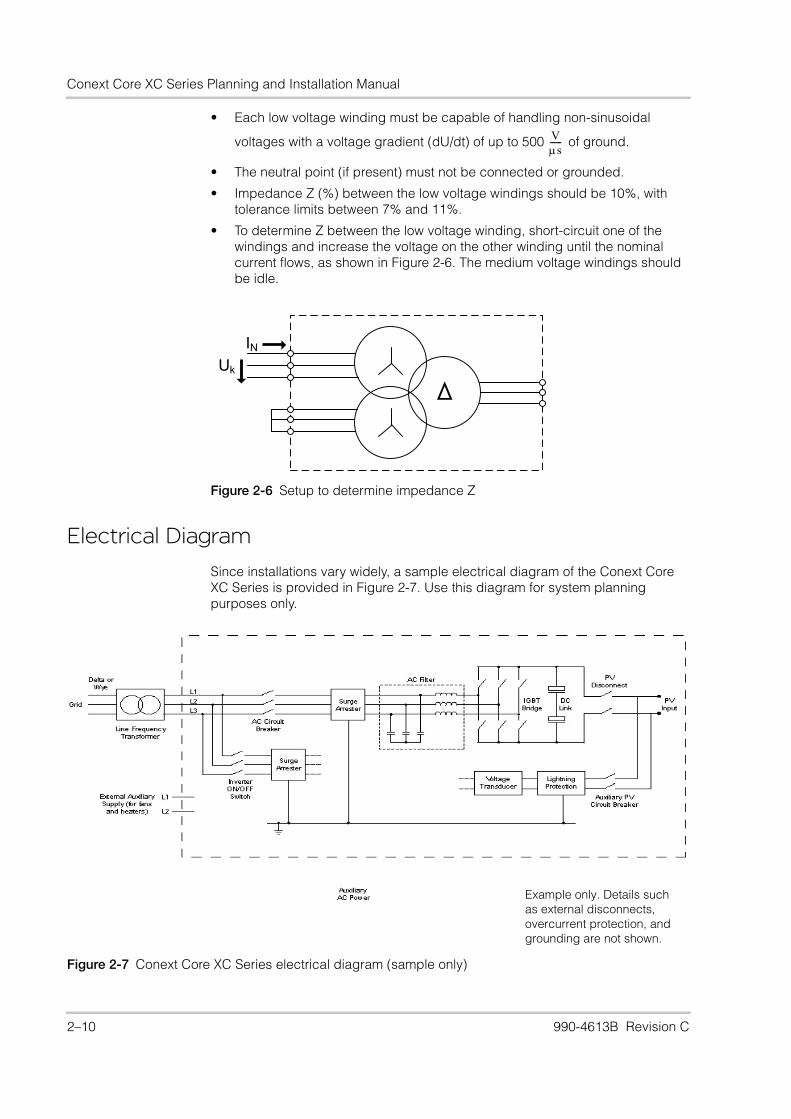
• To determine Z between the low voltage winding, short-circuit one of the windings and increase the voltage on the other winding until the nominal current flows, as shown in Figure 2-6. The medium voltage windings should be idle.
Electrical Diagram
Since installations vary widely, a sample electrical diagram of the Conext Core XC Series is provided in Figure 2-7. Use this diagram for system planning purposes only.
Vs------
Figure 2-6 Setup to determine impedance Z
INUk
Figure 2-7 Conext Core XC Series electrical diagram (sample only)
Example only. Details such as external disconnects, overcurrent protection, and grounding are not shown.
2–10 990-4613B Revision C
3 Installation
DANGER
MULTIPLE SOURCES WITH HAZARD OF ELECTRIC SHOCK, FIRE, EXPLOSION, AND ARC FLASH
• The Conext Core XC Series inverter is energized from the PV array, the AC grid, and the external auxiliary AC source (if used). Before installing the inverter:
– Consult system diagram to identify all sources.
– De-energize, lock out, and tag out all sources following the procedure beginning on page ix.
– Test using a meter rated at least 1000 V AC and DC to ensure all circuits are de-energized.
• The lock-out and tag-out procedure beginning on page ix in this manual only applies to installation of an inverter, not to servicing. If the inverter is already installed, additional steps are needed to de-energize, lock out, tag out, and verify internal voltages, and must only be performed by authorized service personnel. See the Service Bulletin for Conext Core XC Series Inverter Lock-Out and Tag-Out Procedures (document number 993-0438).
• Operation of the switches in or on the inverter does not remove all power from this inverter. Switch terminals remain live unless the PV, AC, and external auxiliary AC source have been disconnected externally.
• Additional external disconnecting means for the PV, AC, and external auxiliary AC source (if used), capable of being locked out and tagged out, must be provided as part of the installation to help facilitate safe installation and for certain servicing operations.
Failure to follow these instructions will result in death or serious injury.
990-4613B Revision C 3–1

Conext Core XC Series Planning and Installation Manual
Unloading
DANGER
HAZARD OF CRUSH INJURY AND EQUIPMENT DAMAGE
• The Conext Core XC Series weighs approximately 1900 kg (4189 lb), including the packing crate and pallet. Attempting to lift or move the inverter by other than the recommended lifting points and methods could cause the inverter to drop unexpectedly or fall over.
• Keep all the doors closed and latched when moving the inverter.
• Use appropriately rated lifting equipment.
Failure to follow these instructions will result in death or serious injury and/or damage to equipment.
NOTICE
EQUIPMENT DAMAGE
Before proceeding with the installation, determine the location and layout of the components, conduit penetration locations, conductor and conduit sizing, and method for anchoring the inverter. Make sure adequate space is provided for clearance for ventilation and serviceability. If necessary, review Chapter 2, “Planning” before proceeding.
Failure to follow these instructions will result in damage to the inverter.
3–2 990-4613B Revision C
Installation: Unloading
Removing the Conext Core XC Series from a Truck
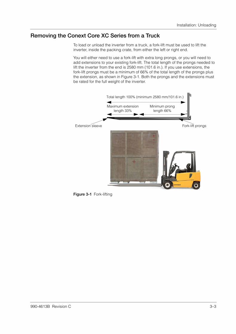
To load or unload the inverter from a truck, a fork-lift must be used to lift the inverter, inside the packing crate, from either the left or right end.
You will either need to use a fork-lift with extra long prongs, or you will need to add extensions to your existing fork-lift. The total length of the prongs needed to lift the inverter from the end is 2580 mm (101.6 in.). If you use extensions, the fork-lift prongs must be a minimum of 66% of the total length of the prongs plus the extension, as shown in Figure 3-1. Both the prongs and the extensions must be rated for the full weight of the inverter.
Figure 3-1 Fork-lifting
Fork-lift prongsExtension sleeve
Total length 100% (minimum 2580 mm/101.6 in.)
Minimum pronglength 66%
Maximum extensionlength 33%
990-4613B Revision C 3–3
Conext Core XC Series Planning and Installation Manual
Removing the Conext Core XC Series from the Pallet
To remove the Conext Core XC Series from the pallet:
1. Do a visual check for any damage to the wooden shipping crate.
2. Disassemble the shipping crate and remove the shrink-wrap from the inverter. Leave the plastic covers over the ventilation grills at the front of the inverter.
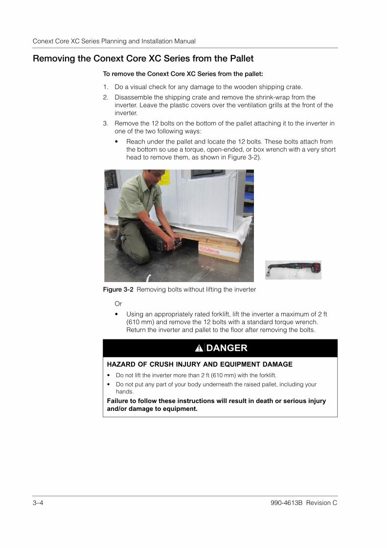
3. Remove the 12 bolts on the bottom of the pallet attaching it to the inverter in one of the two following ways:
• Reach under the pallet and locate the 12 bolts. These bolts attach from the bottom so use a torque, open-ended, or box wrench with a very short head to remove them, as shown in Figure 3-2).
Or
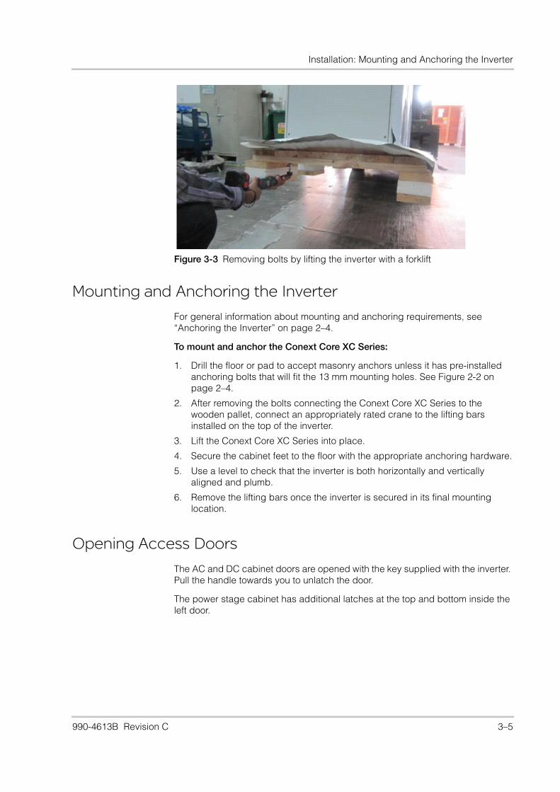
• Using an appropriately rated forklift, lift the inverter a maximum of 2 ft (610 mm) and remove the 12 bolts with a standard torque wrench. Return the inverter and pallet to the floor after removing the bolts.
Figure 3-2 Removing bolts without lifting the inverter
DANGER
HAZARD OF CRUSH INJURY AND EQUIPMENT DAMAGE
• Do not lift the inverter more than 2 ft (610 mm) with the forklift.
• Do not put any part of your body underneath the raised pallet, including your hands.
Failure to follow these instructions will result in death or serious injury and/or damage to equipment.
3–4 990-4613B Revision C
Installation: Mounting and Anchoring the Inverter
Mounting and Anchoring the Inverter
For general information about mounting and anchoring requirements, see “Anchoring the Inverter” on page 2–4.
To mount and anchor the Conext Core XC Series:
1. Drill the floor or pad to accept masonry anchors unless it has pre-installed anchoring bolts that will fit the 13 mm mounting holes. See Figure 2-2 on page 2–4.
2. After removing the bolts connecting the Conext Core XC Series to the wooden pallet, connect an appropriately rated crane to the lifting bars installed on the top of the inverter.
3. Lift the Conext Core XC Series into place.
4. Secure the cabinet feet to the floor with the appropriate anchoring hardware.
5. Use a level to check that the inverter is both horizontally and vertically aligned and plumb.
6. Remove the lifting bars once the inverter is secured in its final mounting location.
Opening Access Doors
The AC and DC cabinet doors are opened with the key supplied with the inverter. Pull the handle towards you to unlatch the door.
The power stage cabinet has additional latches at the top and bottom inside the left door.
Figure 3-3 Removing bolts by lifting the inverter with a forklift
990-4613B Revision C 3–5
Conext Core XC Series Planning and Installation Manual
General Wiring RequirementsAll wiring methods and materials must be in accordance with applicable electrical installation codes. Examples include the US National Electrical Code ANSI/NFPA 70, IEC 60364, CENELEC HD 384, and DIN VDE 0100.
Conductor Termination
The Conext Core XC Series has terminals and bus bars for making all wiring connections required for inverter installation. All terminals used for making AC and DC connections require the use of conductors with an insulation rating of 75 °C (or higher). If conductors rated higher than 75 °C are used, base the wire size on the requirements for 75 °C wire to help prevent excessive heating of the bus bars, terminals, and connected devices.
AC Wiring The AC output phase wiring connects to the AC terminals identified as XT1 (L1, L2, and L3) in the AC cabinet. These terminals require the use of a crimp-on type ring terminal or compression-type lug. Keep the cables close together as much as possible and make sure that all cables pass through the same conduit fittings and the same access point in the floor of the inverter. This allows any inductive currents to cancel.
Each terminal has five bolts per pole and accommodates a maximum of one cable per bolt. For the location of these terminals and wiring instruction see Figure 3-11 on page 3–12. For bolt sizes torque values, see Table A-3 on page A–4. For the dimensions of the terminal lug connections, see Figure 3-4.
NOTICE
EQUIPMENT DAMAGE
When connecting external AC wires to the Conext Core XC Series, positive phasing sequence must be maintained throughout the installation process.
Failure to follow these instruction can result in damage to equipment.
3–6 990-4613B Revision C

Installation: General Wiring Requirements
Auxiliary AC wiring The auxiliary AC input wiring connects to the terminals identified as XT4 (1 and 2) in the AC cabinet. These terminals require a crimp-on ferrule properly sized for the wire and accommodate one wire per terminal. For the location of these terminals, see Figure 3-17 on page 3–18. For bolt sizes and torque values, see Table A-3 on page A–4.
Figure 3-4 AC terminal lug connections
990-4613B Revision C 3–7

Conext Core XC Series Planning and Installation Manual
DC Wiring The PV input wiring connects to the PV terminals identified as PV+ and PV- in the DC cabinet. These terminals require the use of a crimp-on type ring terminal or compression-type lug. Keep the cables close together as much as possible and make sure that all cables pass through the same conduit fittings and the same access point in the floor of the inverter. This allows any inductive currents to cancel.
Each terminal has seven bolts per pole and a maximum of one cable per bolt. For the location of these terminals, see Figure 3-16 on page 3–15. For bolt sizes and torque values, see Table A-4 on page A–4. For the dimensions of the terminal lug connections, see Figure 3-5.
Figure 3-5 DC terminal lug connections
3–8 990-4613B Revision C
Installation: General Wiring Requirements
Grounding
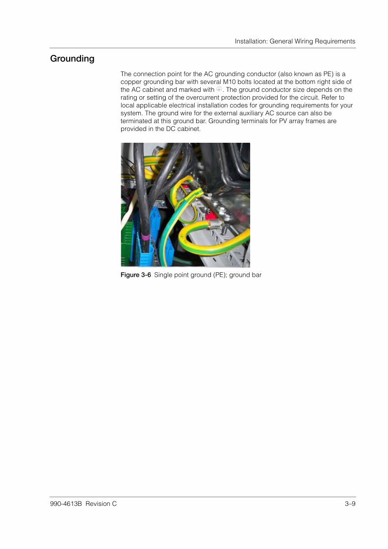
The connection point for the AC grounding conductor (also known as PE) is a copper grounding bar with several M10 bolts located at the bottom right side of the AC cabinet and marked with . The ground conductor size depends on the rating or setting of the overcurrent protection provided for the circuit. Refer to local applicable electrical installation codes for grounding requirements for your system. The ground wire for the external auxiliary AC source can also be terminated at this ground bar. Grounding terminals for PV array frames are provided in the DC cabinet.
Figure 3-6 Single point ground (PE); ground bar
990-4613B Revision C 3–9
Conext Core XC Series Planning and Installation Manual
Specific Wiring RequirementsThis section provides information for connecting the AC, PV, and ground conductors. Table A-3 and Table A-4 on page A–4 show the specifications for the provided wiring terminals.
AC Wiring
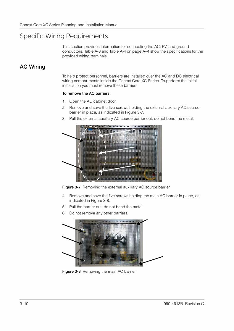
To help protect personnel, barriers are installed over the AC and DC electrical wiring compartments inside the Conext Core XC Series. To perform the initial installation you must remove these barriers.
To remove the AC barriers:
1. Open the AC cabinet door.
2. Remove and save the five screws holding the external auxiliary AC source barrier in place, as indicated in Figure 3-7.
3. Pull the external auxiliary AC source barrier out; do not bend the metal.
4. Remove and save the five screws holding the main AC barrier in place, as indicated in Figure 3-8.
5. Pull the barrier out; do not bend the metal.
6. Do not remove any other barriers.
Figure 3-7 Removing the external auxiliary AC source barrier
Figure 3-8 Removing the main AC barrier
3–10 990-4613B Revision C
Installation: Specific Wiring Requirements
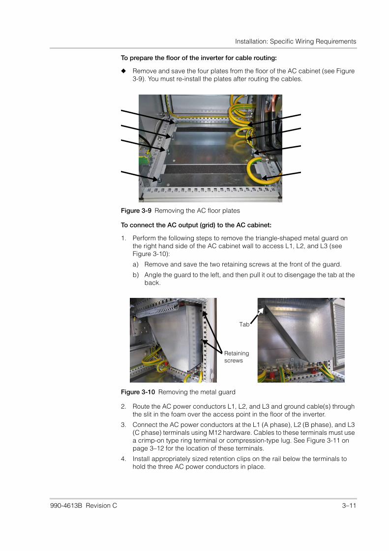
To prepare the floor of the inverter for cable routing:
◆ Remove and save the four plates from the floor of the AC cabinet (see Figure 3-9). You must re-install the plates after routing the cables.
To connect the AC output (grid) to the AC cabinet:
1. Perform the following steps to remove the triangle-shaped metal guard on the right hand side of the AC cabinet wall to access L1, L2, and L3 (see Figure 3-10):
a) Remove and save the two retaining screws at the front of the guard.
b) Angle the guard to the left, and then pull it out to disengage the tab at the back.
2. Route the AC power conductors L1, L2, and L3 and ground cable(s) through the slit in the foam over the access point in the floor of the inverter.
3. Connect the AC power conductors at the L1 (A phase), L2 (B phase), and L3 (C phase) terminals using M12 hardware. Cables to these terminals must use a crimp-on type ring terminal or compression-type lug. See Figure 3-11 on page 3–12 for the location of these terminals.
4. Install appropriately sized retention clips on the rail below the terminals to hold the three AC power conductors in place.
Figure 3-9 Removing the AC floor plates
Figure 3-10 Removing the metal guard
Retaining screws
Tab
990-4613B Revision C 3–11
Conext Core XC Series Planning and Installation Manual
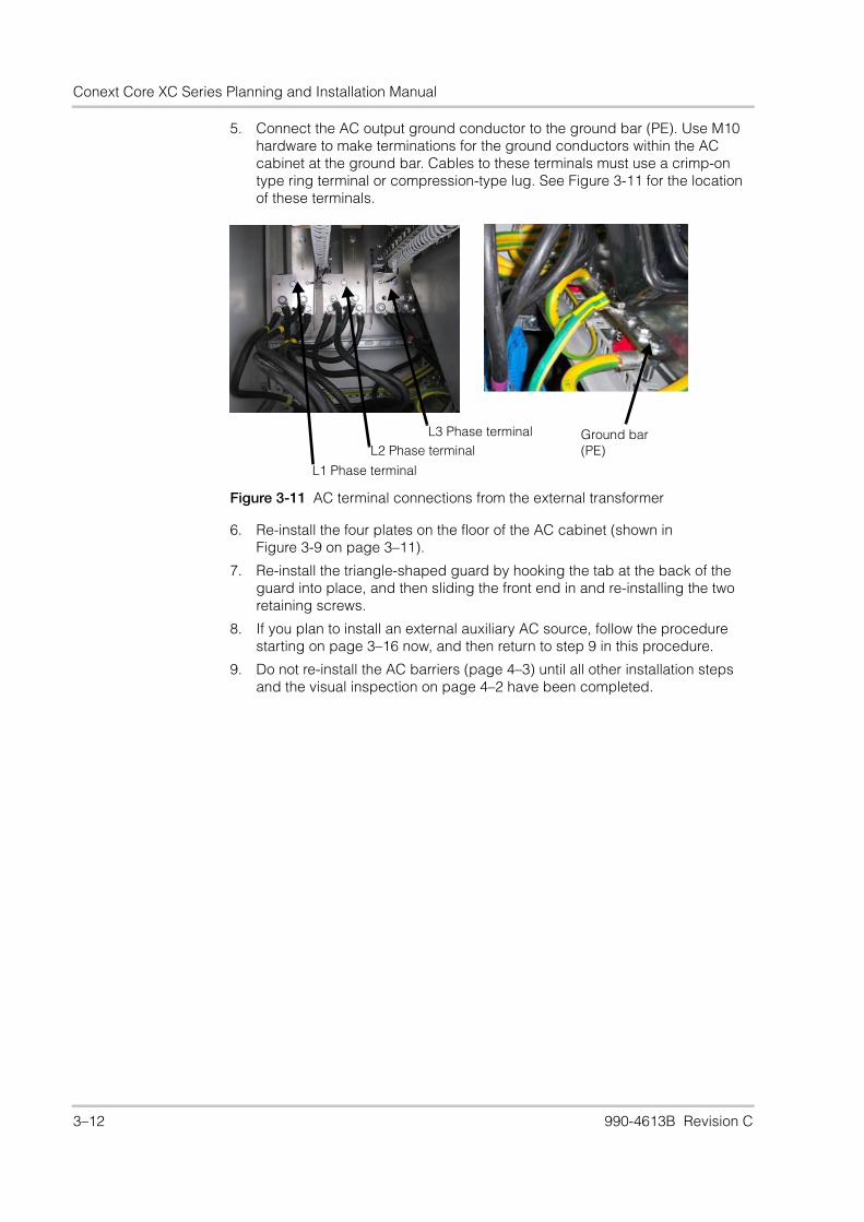
5. Connect the AC output ground conductor to the ground bar (PE). Use M10 hardware to make terminations for the ground conductors within the AC cabinet at the ground bar. Cables to these terminals must use a crimp-on type ring terminal or compression-type lug. See Figure 3-11 for the location of these terminals.
6. Re-install the four plates on the floor of the AC cabinet (shown inFigure 3-9 on page 3–11).
7. Re-install the triangle-shaped guard by hooking the tab at the back of the guard into place, and then sliding the front end in and re-installing the two retaining screws.
8. If you plan to install an external auxiliary AC source, follow the procedure starting on page 3–16 now, and then return to step 9 in this procedure.
9. Do not re-install the AC barriers (page 4–3) until all other installation steps and the visual inspection on page 4–2 have been completed.
Figure 3-11 AC terminal connections from the external transformer
L1 Phase terminal
L3 Phase terminalL2 Phase terminal
Ground bar (PE)
3–12 990-4613B Revision C
Installation: Specific Wiring Requirements
PV Array Wiring
To help protect personnel, the DC cabinet is provided with four barriers:
• A large plastic barrier over the entire upper half of the cabinet.
• A large steel mesh barrier over the entire lower half of the cabinet.
• A small plastic barrier over the PV auxiliary circuit breaker.
• A small plastic barrier over the PV surge protection devices.
These barriers overlap and must be removed in a specific order, as described in the procedure below.
To remove the DC barriers:
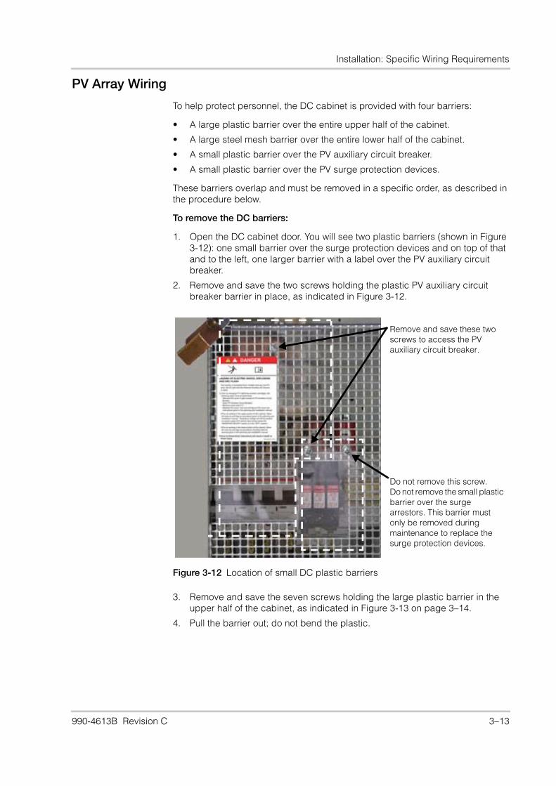
1. Open the DC cabinet door. You will see two plastic barriers (shown in Figure 3-12): one small barrier over the surge protection devices and on top of that and to the left, one larger barrier with a label over the PV auxiliary circuit breaker.
2. Remove and save the two screws holding the plastic PV auxiliary circuit breaker barrier in place, as indicated in Figure 3-12.
3. Remove and save the seven screws holding the large plastic barrier in the upper half of the cabinet, as indicated in Figure 3-13 on page 3–14.
4. Pull the barrier out; do not bend the plastic.
Figure 3-12 Location of small DC plastic barriers
Remove and save these two screws to access the PV auxiliary circuit breaker.
Do not remove this screw. Do not remove the small plastic barrier over the surge arrestors. This barrier must only be removed during maintenance to replace the surge protection devices.
990-4613B Revision C 3–13
Conext Core XC Series Planning and Installation Manual
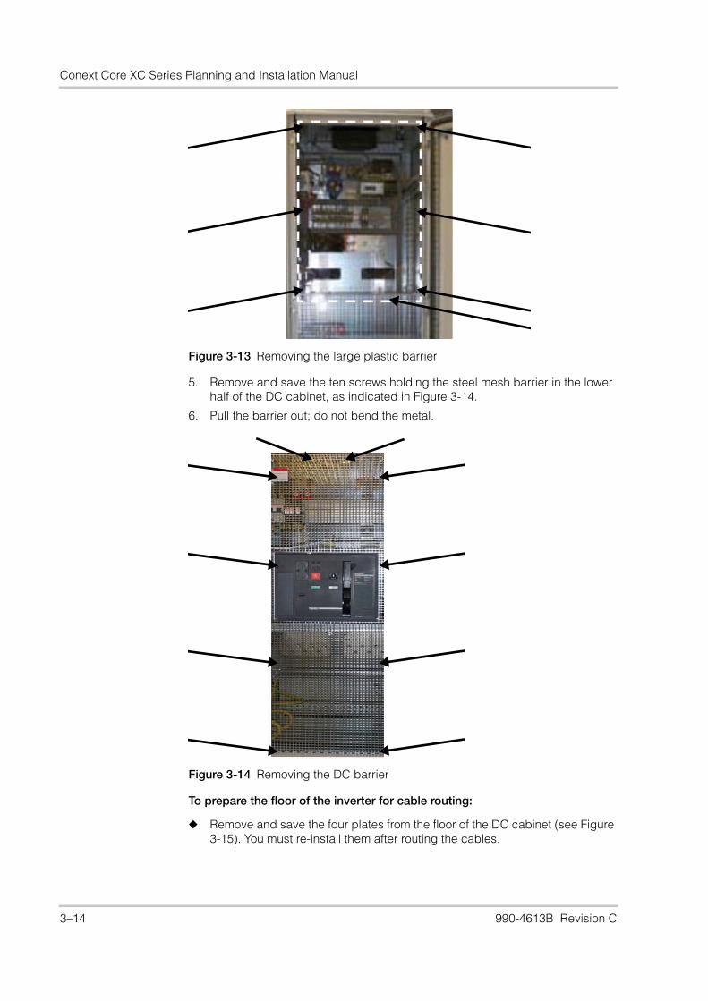
5. Remove and save the ten screws holding the steel mesh barrier in the lower half of the DC cabinet, as indicated in Figure 3-14.
6. Pull the barrier out; do not bend the metal.
To prepare the floor of the inverter for cable routing:
◆ Remove and save the four plates from the floor of the DC cabinet (see Figure 3-15). You must re-install them after routing the cables.
Figure 3-13 Removing the large plastic barrier
Figure 3-14 Removing the DC barrier
3–14 990-4613B Revision C

Installation: Specific Wiring Requirements
To make the connections from the PV array/combiner to DC cabinet:
1. Route the PV+ and PV- power conductors and the PV array frame ground conductor(s) through the slit in the foam in the access point in the floor of the inverter.
2. Terminate the PV power conductors at the PV+ and PV- terminals in the DC cabinet using M12 hardware (see Figure 3-16). Polarity must be observed or the inverter will fail to qualify the PV array voltage and will not generate output power. Conductors must be provided with crimp-on ring terminals or compression-type lugs. Torque the M12 bolts per Table A-4 on page A–4.
3. Connect the ground conductor(s) from the PV array frames to the ground bar (PE) (see Figure 3-16). Make terminations for the ground conductor(s) within the DC cabinet at the ground bar with M10 hardware.
4. Re-install the four plates in the floor of the DC cabinet (shown in Figure 3-15).
5. Do not re-install the DC barriers (page 4–3) until all other installation steps and the visual inspection on page 4–2 have been completed.
Figure 3-15 Removing the DC floor plates
Figure 3-16 PV array cable routing and terminations
PV-
PV+
Ground bar (PE)
990-4613B Revision C 3–15

Conext Core XC Series Planning and Installation Manual
Auxiliary AC Source Wiring
Power for the ventilation fans and heaters is provided by an internal auxiliary AC supply transformer (TC1). The source of supply to that transformer can be configured to be one of the following sources:
• An external auxiliary AC source (a separate source of supply provided at the installation site).
• The inverter AC output circuit.
The transformer has multiple taps that can be selected to allow for different AC supply voltage ranges.
Two different transformer configurations exist for the auxiliary supply transformer (TC1). Original Conext Core XC Series inverters use auxiliary voltages of 208, 230, 315, or 400 VAC rms phase-to-phase. Newer Conext Core XC Series inverters use auxiliary voltages of 208, 230, 300, 350, or 380 VAC rms phase-to-phase.
As shipped, the inverter is configured for auxiliary supply from the external AC auxiliary source and for a voltage of 230 VAC. If a 230 VAC auxiliary supply will be connected to the external AC auxiliary source input terminals (XT4), no further changes to the auxiliary AC source wiring or to the auxiliary AC supply transformer are needed. Proceed to “To connect an external auxiliary AC source to terminal XT4 in the AC cabinet:” on page 3–18.
Changes to the configuration of the auxiliary supply wiring and transformer tap selection will be required if either of the following is true:
• The external AC auxiliary source is being used, but the voltage is not 230 VAC.
• The auxiliary AC will be supplied from the inverter output.
NOTICE
COMPONENT DAMAGE
• For original Conext Core XC Series inverters, auxiliary power can only be supplied from the inverter AC output if the AC output voltage will always be in one of the following ranges:284 — 346 VAC phase-to-phase360 — 440 VAC phase-to-phase
• For newer Conext Core XC Series inverters, auxiliary power can only be supplied from the inverter AC output if the AC output voltage will always be in one of the following ranges:270 — 330 VAC phase-to-phase315— 385 VAC phase-to-phase342— 418 VAC phase-to-phase
• Auxiliary AC supply transformer (TC1) taps must be set correctly according to the information in Table 3-1 or Table 3-2.
Failure to follow these instructions can result in damage to equipment.
3–16 990-4613B Revision C

Installation: Specific Wiring Requirements
External AC Auxiliary Power Source
The external auxiliary AC source must be a nominal voltage that is compatible with the transformer configuration. If the source provided is 230 VAC, no change is needed. If the source provided is 208, 315, or 400 VAC (original configuration) or 208, 300, 350, or 380 VAC (newer configuration), then the tap selection for the auxiliary supply transformer (TC1) must be changed, according to Table 3-1 or Table 3-2. Instructions for changing taps are on page 3–18.
The selection of external over-current protection for the AC auxiliary input circuit of the Conext Core XC Series inverters must be coordinated with both the internal inverter circuitry and your local electrical installation code(s). You must use an external over-current protection device with a maximum thermal trip current of 16A plus a suitable magnetic trip curve. The recommended magnetic trip curve is Type D, but there are many different trip curves available which vary between manufacturers. You may need to test a variety of over-current protection devices with your specific circuit to prevent nuisance tripping.
For original Conext Core XC Series inverters using external auxiliary voltages of 208, 230, 315, or 400 VAC rms phase-to-phase, refer to Table 3-1.
For newer Conext Core XC Series inverters using external auxiliary voltages of 208, 230, 300, 350, or 380 VAC rms phase-to-phase, refer to Table 3-2.
WARNING
HAZARD OF FIRE
External over-current protection must be installed for the AC auxiliary input circuit of the inverter.
Failure to follow these instructions can result in death or serious injury.
Table 3-1 Voltage ranges and transformer taps for external auxiliary AC source(original Conext Core XC Series)
External auxiliary AC source voltage (VAC rms phase to phase)
Auxiliary AC supply transformer (TC1) primary tap
208 (± 10%) 208
230 (± 10%) 230 (as shipped)
315 (± 10%) 315
400 (± 10%) 400
Table 3-2 Voltage ranges and transformer taps for external auxiliary AC source(newer Conext Core XC Series)
External auxiliary AC source voltage (VAC rms phase to phase)
Auxiliary AC supply transformer (TC1) primary tap
208 (± 10%) 208
230 (± 10%) 230 (as shipped)
300 (± 10%) 300
350 (± 10%) 350
380 (± 10%) 380
990-4613B Revision C 3–17
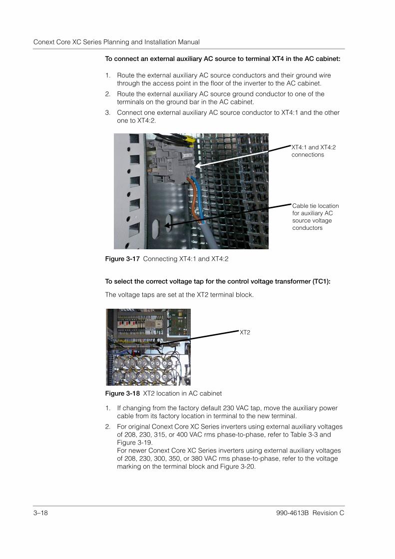
Conext Core XC Series Planning and Installation Manual
To connect an external auxiliary AC source to terminal XT4 in the AC cabinet:
1. Route the external auxiliary AC source conductors and their ground wire through the access point in the floor of the inverter to the AC cabinet.
2. Route the external auxiliary AC source ground conductor to one of the terminals on the ground bar in the AC cabinet.
3. Connect one external auxiliary AC source conductor to XT4:1 and the other one to XT4:2.
To select the correct voltage tap for the control voltage transformer (TC1):
The voltage taps are set at the XT2 terminal block.
1. If changing from the factory default 230 VAC tap, move the auxiliary power cable from its factory location in terminal to the new terminal.
2. For original Conext Core XC Series inverters using external auxiliary voltages of 208, 230, 315, or 400 VAC rms phase-to-phase, refer to Table 3-3 and Figure 3-19.For newer Conext Core XC Series inverters using external auxiliary voltages of 208, 230, 300, 350, or 380 VAC rms phase-to-phase, refer to the voltage marking on the terminal block and Figure 3-20.
Figure 3-17 Connecting XT4:1 and XT4:2
XT4:1 and XT4:2 connections
Cable tie location for auxiliary AC source voltage conductors
Figure 3-18 XT2 location in AC cabinet
XT2
3–18 990-4613B Revision C

Installation: Specific Wiring Requirements
3. Do not re-install the DC barriers (page 4–3) until all other installation steps and the visual inspection on page 4–2 have been completed.
Internal AC Auxiliary Power Source
For original Conext Core XC Series inverters, the auxiliary power supply can be taken from the AC output if the AC output will remain within one of the following ranges under all conditions:
• 284 — 346 VAC phase-to-phase
• 360 — 440 VAC phase-to-phase
Table 3-3 XT2:21 cable location for transformer tap(original Conext Core XC Series)
Cable XT2 location Transformer (TC1) tap
XT2:20 400 V
XT2:21 315 V
XT2:22 230 V (as shipped)
XT2:23 208 V
Figure 3-19 Moving the voltage tap wire (original Conext Core XC Series)
Figure 3-20 Moving the voltage tap wire (newer Conext Core XC Series)
Move cable marked XT2:21 as needed to select voltage
Insert a screwdriver into the hole beneath the old location to open the clip and release the wire.
Insert a screwdriver into the hole beneath the new location to open the clip. Remove the screwdriver to close the clip and grip the wire.
Move the auxiliary power cable as needed to select voltage.
Insert a screwdriver into the hole beneath the old location to open the clip and release the wire.
Insert a screwdriver into the hole beneath the new location to open the clip. Remove the screwdriver to close the clip and grip the wire.
990-4613B Revision C 3–19

Conext Core XC Series Planning and Installation Manual
For newer Conext Core XC Series inverters, the auxiliary power supply can be taken from the AC output if the AC output will remain within one of the following ranges under all conditions:
• 270 — 330 VAC phase-to-phase
• 315— 385 VAC phase-to-phase
• 342— 418 VAC phase-to-phase
If one of these conditions cannot be met, then the auxiliary power must be supplied from an external auxiliary AC source as described on page 3–16.
To configure the inverter for internal auxiliary power supplied from the AC output:
1. Change the factory configuration by moving the conductors connected to terminals XT2:39 and XT2:40 (external supply) over to terminals XT2:45 and XT2:46 (internal supply). See Figure 3-21 for the location of these terminals.
2. Using the procedure “To select the correct voltage tap for the control voltage transformer (TC1):” on page 3–18, adjust the tap selection on XT2 for the auxiliary supply transformer (TC1) according to Table 3-4 (original Conext Core XC Series inverters) or Table 3-5 (newer Conext Core XC Series inverters).
Figure 3-21 XT2 terminal block settings for internal auxiliary AC source
Internal auxiliary supply setting (XT2:45 and XT2:46)
Insert a screwdriver into the hole beneath the old location to open the clip and release the wire.
Insert a screwdriver into the hole beneath the new location to open the clip. Remove the screwdriver to close the clip and grip the wire.
Table 3-4 Tap selection for internal auxiliary AC source connection(original Conext Core XC Series)
AC output voltage (VAC rms phase-to-phase)a
a. Minimum to maximum absolute range.
TC1 primary tap on XT2
284 to 346 315
360 to 440 400
Table 3-5 Tap selection for internal auxiliary AC source connection(newer Conext Core XC Series)
AC output voltage (VAC rms phase-to-phase)a
a. Minimum to maximum absolute range.
TC1 primary tap on XT2
300 (± 10%) 300
350 (± 10%) 350
380 (± 10%) 380
3–20 990-4613B Revision C

Installation: Specific Wiring Requirements
Remote Communication and Control Wiring
In the Conext Core XC Series, the Modbus/RS485 circuits are to be connected only to external Modbus/RS485 circuits that are Safety Extra-Low Voltage (SELV). SELV is a common designation that refers to a circuit in which the voltages within the circuit and from the circuit to ground have values that are not a shock hazard, under both normal and single fault conditions. This is achieved by the design of the circuits, and by maintaining protective separation (fault-tolerant insulation and isolation) between the SELV circuits and all hazardous voltage circuits, both within the inverter and in the installation.
In the Conext Core XC Series, the SELV circuits and their intended connections are:
• The Modbus/RS485 circuits on connectors S43 and S44, which must be connected only to external Modbus/RS485 circuits that are SELV.
• The external ENABLE/DISABLE switch circuit on terminals 5 and 6 of terminal block XT14, which must be connected only to a switch that has dry contacts (with no external voltage applied to them) and has protective separation to hazardous voltage circuits.
• The circuits for external control of active and reactive power, which must be connected only to 4-20 mA loop circuits that are SELV.
Make sure the communication and control cables enter the cabinet away from the PV and AC wiring and are routed and mechanically secured away from the PV and AC wiring throughout the length of the communications and control wiring. Maintain no less than 50 mm (2 in.) separation at all points and use the provided cable channels.
DANGER
HAZARD OF ELECTRIC SHOCK
• Connect only to Safety Extra Low Voltage (SELV) circuits.
• The circuits provided for use with external communications and control equipment are designed to provide isolation from neighboring hazardous circuits within the inverter. The communications and control circuits within the Conext Core XC Series are floating from ground and are classified as SELV. They must be connected only to other SELV circuits in a manner which maintains all the circuits within SELV limits and prevents ground loops. Separate conduit entries must be provided for the communications and control circuits and the PV circuits and all AC circuits.
• Physical and electrical separation of the communications and control circuits from non-SELV electrical circuits must be maintained both within the inverter and external to the inverters.
Failure to follow these instructions will result in death or serious injury.
990-4613B Revision C 3–21
Conext Core XC Series Planning and Installation Manual
Modbus/RS-485 Wiring
Isolation and Surge Protection
The recommended best practice is the use of fiber optic isolation, installed as close to the inverter as possible. This provides full isolation, removing the risk of damaging electrical surges coupling to the inverter, and, therefore, negating the need for additional surge protection.
Daisy-chaining The RS-485 bus is a multi-drop bus implemented as a daisy chain. The Conext Core XC Series provides two RJ-45 connectors to the same modbus ports to facilitate daisy chaining. Either port can be connected to the upstream or downstream device and a standard Ethernet (straight-through) patch cable may be used to connect the devices.
Note: Ethernet cross-over cables must not be used.
Shielding and Grounding
The RJ-45 cable must use a shielded cable with the Modbus master end (not the inverter end) connected to protective ground. On the inverter end, the male connector must be shielded.
NOTICE
HAZARD OF EQUIPMENT DAMAGE
Installations involving non-fiber optic cables exceeding 10 m (32 ft 9¾ inches) outside of a PV Box or building structure to the communication ports of the inverter must be able to withstand a 1.0 kV surge from line to ground. The recommended methods to meet this requirement are listed below in order of best practices:
• Galvanic isolation installed within 10 m (32 ft 9¾ inches) of the inverter – such as, Schneider Electric gateway devices TSXETG100 or EGX300.
• No galvanic isolation – surge protection devices that provide a minimum protection rating of 1.0 kV from line to earth are also acceptable but should be selected in accordance with the Schneider Electric Application Note: Modbus/RS485 Wiring for Conext Core XC inverters (document number: 990-4864).
Failure to follow these instructions can result in damage to equipment.
3–22 990-4613B Revision C
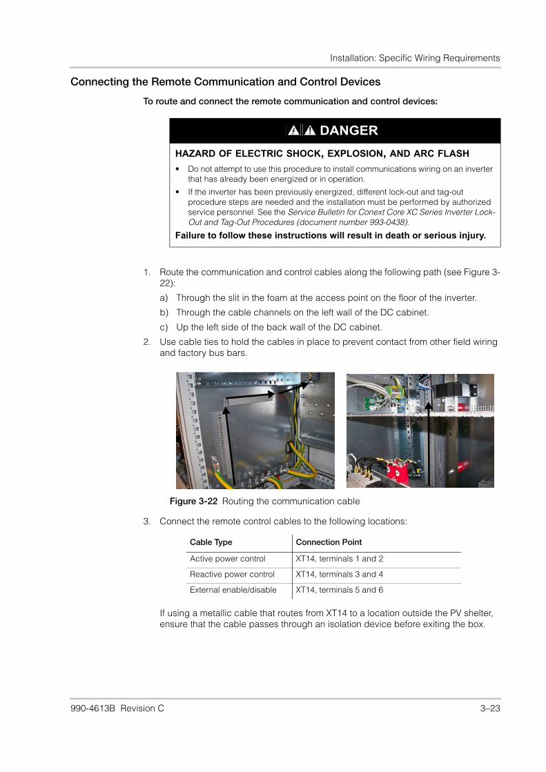
Installation: Specific Wiring Requirements
Connecting the Remote Communication and Control Devices
To route and connect the remote communication and control devices:
1. Route the communication and control cables along the following path (see Figure 3-22):
a) Through the slit in the foam at the access point on the floor of the inverter.
b) Through the cable channels on the left wall of the DC cabinet.
c) Up the left side of the back wall of the DC cabinet.
2. Use cable ties to hold the cables in place to prevent contact from other field wiring and factory bus bars.
3. Connect the remote control cables to the following locations:
If using a metallic cable that routes from XT14 to a location outside the PV shelter, ensure that the cable passes through an isolation device before exiting the box.
DANGER
HAZARD OF ELECTRIC SHOCK, EXPLOSION, AND ARC FLASH
• Do not attempt to use this procedure to install communications wiring on an inverter that has already been energized or in operation.
• If the inverter has been previously energized, different lock-out and tag-out procedure steps are needed and the installation must be performed by authorized service personnel. See the Service Bulletin for Conext Core XC Series Inverter Lock-Out and Tag-Out Procedures (document number 993-0438).
Failure to follow these instructions will result in death or serious injury.
Figure 3-22 Routing the communication cable
Cable Type Connection Point
Active power control XT14, terminals 1 and 2
Reactive power control XT14, terminals 3 and 4
External enable/disable XT14, terminals 5 and 6
990-4613B Revision C 3–23
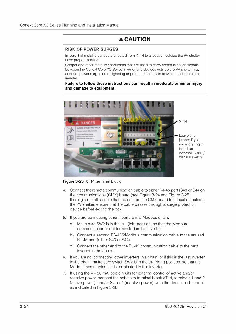
Conext Core XC Series Planning and Installation Manual
4. Connect the remote communication cable to either RJ-45 port (S43 or S44 on the communications (CMX) board (see Figure 3-24 and Figure 3-25.If using a metallic cable that routes from the CMX board to a location outside the PV shelter, ensure that the cable passes through a surge protection device before exiting the box.
5. If you are connecting other inverters in a Modbus chain:
a) Make sure SW2 is in the OFF (left) position, so that the Modbus communication is not terminated in this inverter.
b) Connect a second RS-485/Modbus communication cable to the unused RJ-45 port (either S43 or S44).
c) Connect the other end of the RJ-45 communication cable to the next inverter in the chain.
6. If you are not connecting other inverters in a chain, or if this is the last inverter in the chain, make sure switch SW2 is in the ON (right) position, so that the Modbus communication is terminated in this inverter.
7. If using the 4 – 20 mA loop circuits for external control of active and/or reactive power, connect the cables to terminal block XT14, terminals 1 and 2 (active power), and/or 3 and 4 (reactive power), with the direction of current as indicated in Figure 3-26.
CAUTION
RISK OF POWER SURGES
Ensure that metallic conductors routed from XT14 to a location outside the PV shelter have proper isolation.Copper and other metallic conductors that are used to carry communication signals between the Conext Core XC Series inverter and devices outside the PV shelter may conduct power surges (from lightning or ground differentials between nodes) into the inverter.
Failure to follow these instructions can result in moderate or minor injury and damage to equipment.
Figure 3-23 XT14 terminal block
XT14
Leave this jumper if you are not going to install an external ENABLE/DISABLE switch
3–24 990-4613B Revision C

Installation: Specific Wiring Requirements
8. Do not use the ports labelled CAN IN or CAN OUT. Make sure switch SW1 is set to ON (right).
9. Do not re-install the DC barriers (page 4–3) until all other installation steps and the visual inspection on page 4–2 have been completed.
Figure 3-24 Connecting the communication cable
Figure 3-25 Modbus/RJ-45 pinouts
RS-485/Modbus Do not use
SW2 SW1
Service use only
990-4613B Revision C 3–25
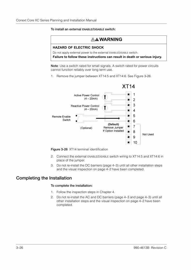
Conext Core XC Series Planning and Installation Manual
To install an external ENABLE/DISABLE switch:
Note: Use a switch rated for small signals. A switch rated for power circuits cannot function reliably over long term use.
1. Remove the jumper between XT14:5 and XT14:6. See Figure 3-26.
2. Connect the external ENABLE/DISABLE switch wiring to XT14:5 and XT14:6 in place of the jumper.
3. Do not re-install the DC barriers (page 4–3) until all other installation steps and the visual inspection on page 4–2 have been completed.
Completing the Installation
To complete the installation:
1. Follow the inspection steps in Chapter 4.
2. Do not re-install the AC and DC barriers (page 4–3 and page 4–3) until all other installation steps and the visual inspection on page 4–2 have been completed.
WARNING
HAZARD OF ELECTRIC SHOCK
Do not apply external power to the external ENABLE/DISABLE switch.
Failure to follow these instructions can result in death or serious injury.
Figure 3-26 XT14 terminal identification
3–26 990-4613B Revision C
4 Inspection
DANGER/
HAZARD OF ELECTRIC SHOCK, FIRE, EXPLOSION, AND ARC FLASH
• To be installed and serviced only by qualified personnel equipped with appropriate personal protective equipment and following safe electrical work practices.
• This inverter is energized from multiple sources: the PV array, the AC grid, and the
external auxiliary AC source (if used). Before opening doorsa or covers:
– Consult system diagram to identify all sources.
– De-energize, lock out, and tag out all sources following the procedure beginning on page ix.
– Wait at least 15 minutes for internal capacitors to discharge to safe voltages.
• Operation of the switches in or on the inverter does not remove all power from this inverter. Switch terminals remain live unless the PV, AC, and external auxiliary AC source have been disconnected externally.
• Before servicing, test using a meter rated at least 1000 V AC and DC, to ensure all circuits are de-energized.
• Additional external disconnecting means for the PV, AC, and external auxiliary AC source (if used), capable of being locked out and tagged out, must be provided as part of the installation to help facilitate safe installation and for certain servicing operations.
Failure to follow these instructions will result in death or serious injury.
a. A maintenance feature is available for equipped inverters that will allow the DC cabinet door tobe opened without interrupting inverter operation (opening any other doors will interrupt inverteroperation). Check with your country sales organization to determine whether your inverter isequipped with this feature.
990-4613B Revision C 4–1
Conext Core XC Series Planning and Installation Manual
Visual InspectionThese procedures help verify correct installation and proper wiring of the Conext Core XC Series. Prior to performing the following inspection steps on the Conext Core XC Series, review all safety requirements and procedures outlined in this manual and on any cautionary markings on the components within the system.
To inspect the installation:
1. Visually inspect all the mechanical connections. This includes both electrical conduit fittings as well as cabinet anchoring and seismic bracing, if required.
2. Visually inspect the electrical connections and verify proper tightness of all terminations.
3. Visually inspect the utility interconnection transformer connections. Verify that the inverter-side winding of the transformer is not connected to ground at any point.
4. Visually inspect terminal block XT2 for correct tapping for both internal or external auxiliary AC power supply and for system voltage (see “Auxiliary AC Source Wiring” on page 3–16).
5. Perform corrective actions, if required.
NOTICE
EQUIPMENT DAMAGE
Do not connect any point on the inverter-side winding of the isolation transformer to ground.
Failure to follow these instruction will result in damage to the inverter.
4–2 990-4613B Revision C
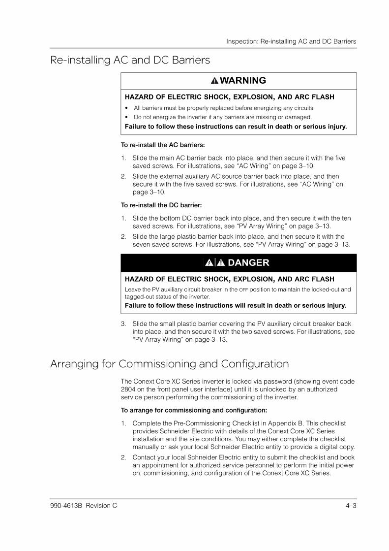
Inspection: Re-installing AC and DC Barriers
Re-installing AC and DC Barriers
To re-install the AC barriers:
1. Slide the main AC barrier back into place, and then secure it with the five saved screws. For illustrations, see “AC Wiring” on page 3–10.
2. Slide the external auxiliary AC source barrier back into place, and then secure it with the five saved screws. For illustrations, see “AC Wiring” on page 3–10.
To re-install the DC barrier:
1. Slide the bottom DC barrier back into place, and then secure it with the ten saved screws. For illustrations, see “PV Array Wiring” on page 3–13.
2. Slide the large plastic barrier back into place, and then secure it with the seven saved screws. For illustrations, see “PV Array Wiring” on page 3–13.
3. Slide the small plastic barrier covering the PV auxiliary circuit breaker back into place, and then secure it with the two saved screws. For illustrations, see “PV Array Wiring” on page 3–13.
Arranging for Commissioning and Configuration
The Conext Core XC Series inverter is locked via password (showing event code 2804 on the front panel user interface) until it is unlocked by an authorized service person performing the commissioning of the inverter.
To arrange for commissioning and configuration:
1. Complete the Pre-Commissioning Checklist in Appendix B. This checklist provides Schneider Electric with details of the Conext Core XC Series installation and the site conditions. You may either complete the checklist manually or ask your local Schneider Electric entity to provide a digital copy.
2. Contact your local Schneider Electric entity to submit the checklist and book an appointment for authorized service personnel to perform the initial power on, commissioning, and configuration of the Conext Core XC Series.
WARNING
HAZARD OF ELECTRIC SHOCK, EXPLOSION, AND ARC FLASH
• All barriers must be properly replaced before energizing any circuits.
• Do not energize the inverter if any barriers are missing or damaged.
Failure to follow these instructions can result in death or serious injury.
DANGER
HAZARD OF ELECTRIC SHOCK, EXPLOSION, AND ARC FLASH
Leave the PV auxiliary circuit breaker in the OFF position to maintain the locked-out and tagged-out status of the inverter.
Failure to follow these instructions will result in death or serious injury.
990-4613B Revision C 4–3

4–4

A Specifications
Appendix A provides electrical, environmental and mechanical specifications for the Conext Core XC Series.
WARNING
HAZARD OF ELECTRIC SHOCK, EXPLOSION, FIRE, AND ARC FLASH HAZARD OF EQUIPMENT DAMAGE
Unsafe conditions and damage to the inverter can result if the instructions and electrical, physical, and environmental installation specifications in this manual are not obeyed.
Failure to follow these instructions can result in death or serious injury and/or damage to equipment.
990-4613B Revision C A–1
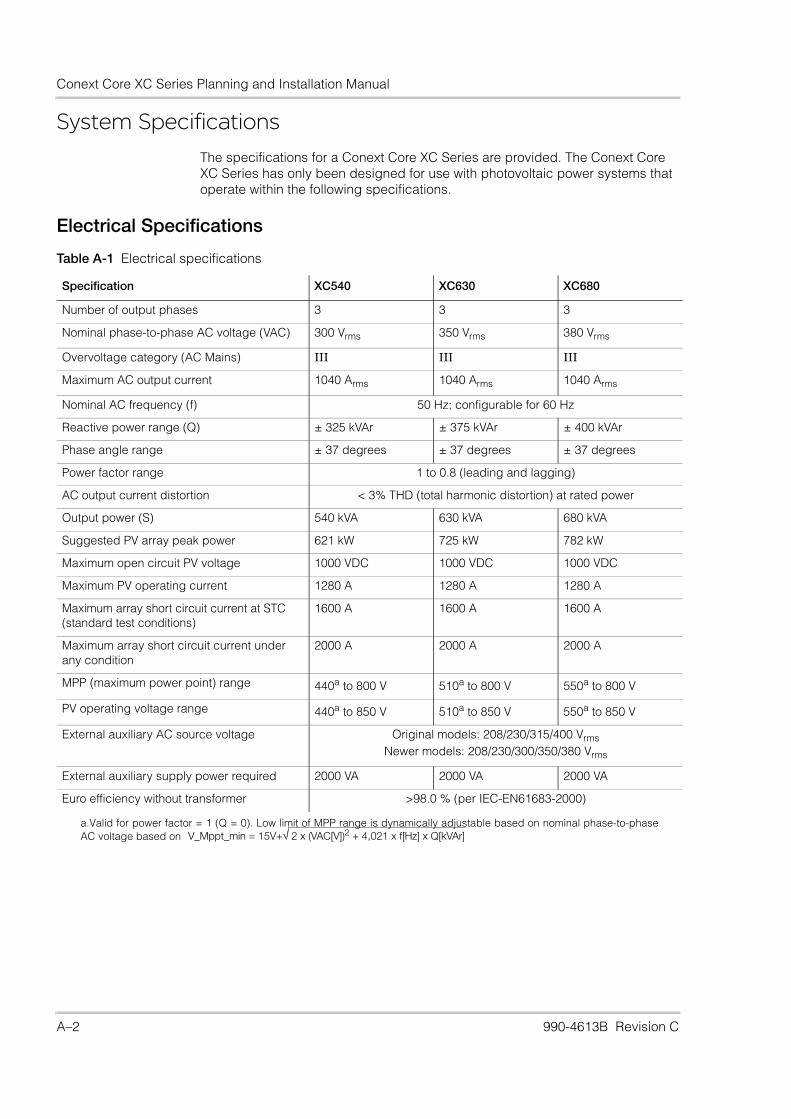
Conext Core XC Series Planning and Installation Manual
System SpecificationsThe specifications for a Conext Core XC Series are provided. The Conext Core XC Series has only been designed for use with photovoltaic power systems that operate within the following specifications.
Electrical Specifications
Table A-1 Electrical specifications
Specification XC540 XC630 XC680
Number of output phases 3 3 3
Nominal phase-to-phase AC voltage (VAC) 300 Vrms 350 Vrms 380 Vrms
Overvoltage category (AC Mains) III III III
Maximum AC output current 1040 Arms 1040 Arms 1040 Arms
Nominal AC frequency (f) 50 Hz; configurable for 60 Hz
Reactive power range (Q) ± 325 kVAr ± 375 kVAr ± 400 kVAr
Phase angle range ± 37 degrees ± 37 degrees ± 37 degrees
Power factor range 1 to 0.8 (leading and lagging)
AC output current distortion < 3% THD (total harmonic distortion) at rated power
Output power (S) 540 kVA 630 kVA 680 kVA
Suggested PV array peak power 621 kW 725 kW 782 kW
Maximum open circuit PV voltage 1000 VDC 1000 VDC 1000 VDC
Maximum PV operating current 1280 A 1280 A 1280 A
Maximum array short circuit current at STC (standard test conditions)
1600 A 1600 A 1600 A
Maximum array short circuit current under any condition
2000 A 2000 A 2000 A
MPP (maximum power point) range 440a to 800 V
a.Valid for power factor = 1 (Q = 0). Low limit of MPP range is dynamically adjustable based on nominal phase-to-phaseAC voltage based on
510a to 800 V 550a to 800 V
PV operating voltage range 440a to 850 V 510a to 850 V 550a to 850 V
External auxiliary AC source voltage Original models: 208/230/315/400 VrmsNewer models: 208/230/300/350/380 Vrms
External auxiliary supply power required 2000 VA 2000 VA 2000 VA
Euro efficiency without transformer >98.0 % (per IEC-EN61683-2000)
V_Mppt_min = 15V+ 2 x (VAC[V])2 + 4,021 x f[Hz] x Q[kVAr]
A–2 990-4613B Revision C

Specifications: System Specifications
Physical and Environmental Specifications
Table A-2 shows the physical and environmental specifications for the Conext Core XC Series inverter.
Table A-2 Physical and environmental specifications
Specification Conext Core XC Series
Dimensions 2400 mm W x 2085 mm H x 660 mm D (see Figure A-1)94½ in. W x 82 in. H x 26 in. D
Net weight 1590 kg (3505 lbs)
Gross shipping weight (approximate) 1900 kg (4189 lbs)
Allowable ambient temperature and humidity rangesa
a.Environmental range ratings correlate approximately to Classes shown, as defined by EN60721 standard series.
Operating: Class 3K3:-10 °C to 45 °C maximum (14 °F to 113 °F)b
Maximum 95% relative humidity, non-condensing
b.Above 45 °C (113 °F), the inverter will derate its power output up to 50 °C (122 °F).
Transport: Class 2K2: -25 °C to 55 °C maximum (-13 °F to 131 °F)Maximum 95% relative humidity, non-condensing
Storage: Class 1K2: -25 °C to 55 °C maximum (-13 °F to 131 °F)Maximum 95% relative humidity, non-condensing
Special climatic conditions Operating: Class 3Z1a Transport: Class 2Z1a
Storage: Class 1Z1a
Biological conditions Operating: Class 3B1a Transport: Class 2B1a Storage: Class 1B1a
Chemically active substances Operating: Class 3C1a
Transport: Class 2C1a Storage: Class 1C1a
Mechanically active substances Operating: Class 3S1a Transport: Class 2S1a
Storage: Class 1S1a
Mechanical conditions Operating: Class 3M1a Transport: Class 2M1a Storage: Class 1M1a
Altitude 1000m with no deratingsc
c.Depending on ambient temperature at altitude, the output power may automatically derate above 1000 m.The installer must derate the PV and AC voltages above 2000 m. See “Application Note: Altitude Derating for Conext Core XC Series”.
Storage air pressure 700 to 1060 mbar
Ingress protection class IP20
Cooling air flow power stage cabinet 3000 m³/h
Cooling air flow AC/DC cabinet 500 m³/h each cabinet
Total cooling air flow 4000 m³/h
Clearance (ventilation and serviceability) Top: 300 mm (11¾ in.)Front: 1 m (39½ in.) plus local safety standards for door clearance
990-4613B Revision C A–3

Conext Core XC Series Planning and Installation Manual
Regulatory Specifications
Regulatory specifications for the Conext Core XC Series are:
• CE marked for the Low Voltage Directive per EN50178 and EN 60529-1.
• CE marked for the EMC Directive per EN61000-6-4 (emissions) and EN61000-6-2 (immunity).
• For interconnect and country-specific regulatory compliance information, go to www.schneider-electric.com or speak with your country sales representative.
Bolt Sizes and Torque RequirementsTable A-3 provides acceptable bolt sizes and torque values for AC terminal connections.
Table A-4 provides acceptable bolt sizes and torque values for PV terminal connections.
Table A-3 AC terminal bolt size and torque values
AC TerminalConnections # of Terminals
Max # Conductors per Terminal
Bolt(Hardware) Size
TorqueRequirements
Grounding (PE) 1 2 M12 60 to 70 Nm(44 to 51.5 lb ft)
AC output/grid (XT1) 3 (L1, L2, L3) 5 M12 60 to 70 Nm(44 to 51.5 lb ft)
External auxiliary AC source (XT4)
2 (L1, L2) 1 • cable cross section 2.5 - 10 mm²
• use appropriate ferrules
0.6 – 0.8 Nm(5.3 – 7.1 lb in)
Table A-4 PV terminal bolt size and torque values
DC TerminalConnections # of Terminals
Max # Conductors per Terminal
Bolt(Hardware) Size
TorqueRequirements
PV Terminal (XT11) 2 (PV+, PV-) 7 M12 60 to 70 Nm(44 to 51.5 lb ft)
A–4 990-4613B Revision C

Specifications: Dimensions
Dimensions
Figure A-1 Conext Core XC Series dimensions (XC680 model shown)
2400
2085
600660
Dimensions in mm
990-4613B Revision C A–5

A–6

B Site Evaluation Checklist
990-4613B Revision C B–1

Conext Core XC Series Planning and Installation Manual
B–2 990-4613B Revision C
Page 1 of 2April 2013 When printed, this document is uncontrolled. Confidential - Property of Schneider Electric - Solar Business
Use this checklist to record details of the site configuration and to verify correct installation of the inverter before a Schneider Electric technician is sent on site to commission the inverter.
Grid-Tie Photovoltaic InvertersSite Evaluation Checklist
Document Number 990-5118 Rev A
Inspector Name & Phone Number: Inspection Date:
Project Information
Project name: Street address (if applicable):
GPS coordinates:
Site Contacts
Project manager: Security officer:
Maintenance technician: MV transformer operator:
Other teams that work on site (who, when, where, point of contact):
Safety
Safety protocol (e.g., boots, hard hat, etc.):
Entrance requirements (contact person, location of keys, sign in/out procedure):
1. Site Readiness 3. PV Box (cont’d)
Cabling done percentages: AC cabling done: ____%DC cabling done: ____%
Is an exhaust ventilation system installed? If possible, attach a diagram.
Yes __# of filters ___
No __
Grid availability date _____ (ddmmyy) Are exhaust fans (if installed) speed controlled? Yes __Type: ______
No __
Is inverter anchoring complete? Yes __ No __ Cooling air flow: ____ m3/hr (__ CFM)
Is ducting complete? Yes __ No __ Is air conditioning installed? Yes __ No __
2. Environment If yes, record the cooling capacity: ____ tonnage (____ BTU)
Ambient temperature range: Min __ °C (__ °F)Max __ °C (__ °F)
If a duct system is used, are dampers provided? Yes __ No __
Altitude: ____ m (__ ft) AC cable type: Copper __ Aluminum __
Array tracking axis: None __Single __
Double __ AC cable shielding: Shielded __ Armored __
Describe any shading concerns: AC cable area: ___ sq. mm (___sq. ft.)
No. of AC cable runs per phase: ___ runs/phase
3. PV Box DC cable type: Copper __ Aluminum __
Height: ______ m (______ in.) DC cable shielding: Shielded __ Armored __
Number of inverters per PV box: ____ /PV box DC cable area: _____ sq. mm (_____sq. ft.)
Service access at front of inverter: ______ m (______ in.) No. of DC cable runs per polarity (+/-): ___ PV+ runs ___ PV- runs
Service access at top of inverter: ______ m (______ in.) Is the inverter chassis connected to ground? Yes __ No __
Service power receptacle easily accessible? Yes __ No __ Ground cable type: Copper __ Aluminum __
Type of lighting: _______________________ Ground cable shielding: Shielded __ Armored __
Box construction material: _______________________ Ground cable area: ___ sq. mm (___sq. ft.)
Is the floor level? Yes __ No __ Describe any accessibility problems with the PV box:
Is an intake ventilation/filtration system installed? If possible, attach a diagram.
Yes __# of filters ___
No __
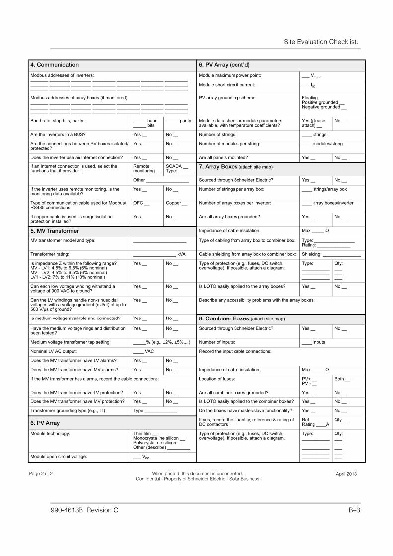
Site Evaluation Checklist:
990-4613B Revision C B–3
Page 2 of 2 April 2013When printed, this document is uncontrolled. Confidential - Property of Schneider Electric - Solar Business
4. Communication 6. PV Array (cont’d)
Modbus addresses of inverters:_______ ________ ________ _________ _________ _________ ________________ ________ ________ _________ _________ _________ ________________ ________ ________ _________ _________ _________ _________
Module maximum power point: ___ Vmpp
Module short circuit current: ___ Isc
Modbus addresses of array boxes (if monitored):_______ ________ ________ _________ _________ _________ ________________ ________ ________ _________ _________ _________ ________________ ________ ________ _________ _________ _________ _________
PV array grounding scheme: Floating __Positive grounded __Negative grounded __
Baud rate, stop bits, parity: _____ baud_____ bits
_____ parity Module data sheet or module parameters available, with temperature coefficients?
Yes (please attach) __
No __
Are the inverters in a BUS? Yes __ No __ Number of strings: ____ strings
Are the connections between PV boxes isolated/protected?
Yes __ No __ Number of modules per string: ____ modules/string
Does the inverter use an Internet connection? Yes __ No __ Are all panels mounted? Yes __ No __
If an Internet connection is used, select the functions that it provides:
Remotemonitoring __
SCADA __ Type:______
7. Array Boxes (attach site map)
Other _________________ Sourced through Schneider Electric? Yes __ No __
If the inverter uses remote monitoring, is the monitoring data available?
Yes __ No __ Number of strings per array box: ____ strings/array box
Type of communication cable used for Modbus/RS485 connections:
OFC __ Copper __ Number of array boxes per inverter: ____ array boxes/inverter
If copper cable is used, is surge isolation protection installed?
Yes __ No __ Are all array boxes grounded? Yes __ No __
5. MV Transformer Impedance of cable insulation: Max _____
MV transformer model and type: _____________________ Type of cabling from array box to combiner box: Type: ________________Rating: _____________
Transformer rating: _________________ kVA Cable shielding from array box to combiner box: Shielding: _______________
Is impedance Z within the following range?MV - LV1: 4.5% to 6.5% (6% nominal)MV - LV2: 4.5% to 6.5% (6% nominal)LV1 - LV2: 7% to 11% (10% nominal)
Yes __ No __ Type of protection (e.g., fuses, DC switch, overvoltage). If possible, attach a diagram.
Type:_________________________________
Qty:_________
Can each low voltage winding withstand a voltage of 900 VAC to ground?
Yes __ No __ Is LOTO easily applied to the array boxes? Yes __ No __
Can the LV windings handle non-sinusoidalvoltages with a voltage gradient (dU/dt) of up to 500 V/µs of ground?
Yes __ No __ Describe any accessibility problems with the array boxes:
Is medium voltage available and connected? Yes __ No __ 8. Combiner Boxes (attach site map)
Have the medium voltage rings and distribution been tested?
Yes __ No __ Sourced through Schneider Electric? Yes __ No __
Medium voltage transformer tap setting: _____% (e.g., ±2%, ±5%,...) Number of inputs: ____ inputs
Nominal LV AC output: ____ VAC Record the input cable connections:
Does the MV transformer have LV alarms? Yes __ No __
Does the MV transformer have MV alarms? Yes __ No __ Impedance of cable insulation: Max _____
If the MV transformer has alarms, record the cable connections: Location of fuses: PV+ __PV - __
Both __
Does the MV transformer have LV protection? Yes __ No __ Are all combiner boxes grounded? Yes __ No __
Does the MV transformer have MV protection? Yes __ No __ Is LOTO easily applied to the combiner boxes? Yes __ No __
Transformer grounding type (e.g., IT) Type _____________ Do the boxes have master/slave functionality? Yes __ No __
6. PV ArrayIf yes, record the quantity, reference & rating of DC contactors
Ref _______Rating ____A
Qty __
Module technology: Thin film __Monocrystalline silicon __Polycrystalline silicon __Other (describe) _________
Type of protection (e.g., fuses, DC switch, overvoltage). If possible, attach a diagram.
Type:_______________________________________________________
Qty:_______________Module open circuit voltage: ___ Voc

B–
4

Printed in990-4613B Revision C
Schneider Electricwww.schneider-electric.com
For other country details please contact your local Schneider Electric Sales Representative or visit the Schneider Electric website at:http://www.schneider-electric.com/sites/corporate/en/support/operations/local-operations/local-operations.page
Related Documents


![[XLS] · Web view400 630 630 400 630 990 990 630 630 630 630 990 990 990 990 990 990 400 400 990 630 990 630 630 400 990 990 990 990 990 630 630 990 990 630 630 990 990 990 990 990](https://static.cupdf.com/doc/110x72/5af695027f8b9a5b1e8f4d8f/xls-view400-630-630-400-630-990-990-630-630-630-630-990-990-990-990-990-990-400.jpg)
