1 Code description example S* (T) (NC) -XB*-* * 2WP || | ||| | | 1 2 3 456 7 8 1. 1 = Unit size 2 to 10. 2. T = Optional Twin (run & standby) extract fan; available as vertical stacked XBV for sizes S2 - 6T and S8T or horizontal XBH for size S8T. 3. Ecosmart control as standard. NC = optional no control version, FC = optional fan speed control only. 4. V = Vertically stacked unit, H = side-by-side unit (available for S6 to S10 only). 5. L = Left hand, R = right hand (see illustrations). 6. E = Electric heater (sizes 2 to 8 inclusive), L = LPHW coil, N = No heater fitted. 7. 2 = 2 row heating coil. 8. WP = Optional weatherproof cover. Example: S2-XBV-LE is size 2, vertically stacked with electric heater and left hand access. S6NC-XBH-RL is a size 6 with no controls, horizontal side-by-side unit, right hand access and LPHW heating coil. SQURBO XBOX (Pre-packaged heat recovery unit) Installation, Operating and Maintenance Instructions The EMC Directive 2014/30/EU The Low Voltage directive 2014/35/EU Figure 2: S2/5-XBV-RN (right hand with no heater). Figure 1: S2/5-XBV-LE (left hand with electric heater). Nuaire Limited Western Industrial Estate Caerphilly United Kingdom CF83 1NA T: 029 2085 8400 F: 029 2085 8444 E: [email protected] W: www.nuaire.co.uk 26. 01. 17. Leaflet Number 671408 Figure 5: S7/8-XBH-RE (right hand with electric heater).5 Intake Exhaust Extract Supply Figure 3: S6-XBH-RE (right hand with electric heater). Intake Exhaust Extract Supply Figure 4: S6-XBV-LE (left hand with electric heater). Supply Extract Exhaust Intake Figure 6: S7/8-XBV-RL (right hand with LPHW). AHU with Heat Recovery section and direct drive AC motor technology. AHU with Heat Recovery section and direct drive EC motor technology. AHU with Heat Recovery section and direct drive AC motor/Inverter technology. Supply Extract Exhaust Intake Exhaust Intake Supply Extract Exhaust Intake Supply Extract

Welcome message from author
This document is posted to help you gain knowledge. Please leave a comment to let me know what you think about it! Share it to your friends and learn new things together.
Transcript

1
Code description example
S* (T) (NC) -XB*-* * 2WP| | | ||| | |1 2 3 456 7 8
1. 1 = Unit size 2 to 10.
2. T = Optional Twin (run & standby) extract fan; available asvertical stacked XBV for sizes S2 - 6T and S8T or horizontalXBH for size S8T.
3. Ecosmart control as standard. NC = optional no control version,FC = optional fan speed control only.
4. V = Vertically stacked unit, H = side-by-side unit (available forS6 to S10 only).
5. L = Left hand, R = right hand (see illustrations).
6. E = Electric heater (sizes 2 to 8 inclusive), L = LPHW coil,N = No heater fitted.
7. 2 = 2 row heating coil.
8. WP = Optional weatherproof cover.
Example: S2-XBV-LE is size 2, vertically stacked with electric heaterand left hand access.
S6NC-XBH-RL is a size 6 with no controls, horizontal side-by-sideunit, right hand access and LPHW heating coil.
SQURBO XBOX(Pre-packaged heat recovery unit)
Installation, Operating andMaintenance Instructions
The EMC Directive 2014/30/EU The Low Voltage directive 2014/35/EU
Figure 2: S2/5-XBV-RN (right hand with no heater).Figure 1: S2/5-XBV-LE (left hand with electric heater).
Nuaire Limited Western Industrial Estate Caerphilly United Kingdom CF83 1NA T: 029 2085 8400 F: 029 2085 8444 E: [email protected] W: www.nuaire.co.uk
26. 01. 17. Leaflet Number 671408
Figure 5: S7/8-XBH-RE (right hand with electric heater).5
Intake
Exhaust
Extract
Supply
Figure 3: S6-XBH-RE (right hand with electric heater).
Intake
Exhaust
Extract
Supply
Figure 4: S6-XBV-LE (left hand with electric heater).
Supply
Extract
Exhaust
Intake
Figure 6: S7/8-XBV-RL (right hand with LPHW).
AHU with Heat Recovery section and direct drive AC motor technology.
AHU with Heat Recovery section and direct drive EC motor technology.
AHU with Heat Recovery section and direct drive AC motor/Inverter technology.
Supply
Extract
Exhaust
Intake
Exhaust
Intake
Supply
Extract
Exhaust
Intake Supply
Extract

Installation, Operating and Maintenance Instructions SQURBO XBOX
1.0 General
The information contained in this document gives details of operation and maintenance for installers and users of NuaireSQURBO XBOX equipment.
These air handling units comprise a combination of modular sections assembled (at works or on site) to suit the applicationrequirements as specified by the purchaser.
General information regarding performance and specifications forthe equipment may be obtained from our Technical Literature, and /or project specific documentation.
2.0 Delivery of Equipment2.1 Receipt of equipmentAll equipment is inspected prior to despatch and leaves the factoryin good condition. Upon receipt of the equipment an inspectionshould be made and any damage indicated on the delivery note.
Particulars of damage and/or incomplete delivery should beendorsed by the driver delivering the goods before offloading bythe purchaser.
No responsibility will be accepted for damage sustained during theoffloading from the vehicle or on the site thereafter.
All claims for damage and/or incomplete delivery must be reportedto Nuaire within two days of receipt of the equipment.
2.2 Offloading and Handling from thedelivery Vehicle The weight of the unit modules and palletised items is displayed onthe unit rating plate or on the packaging. Some of the moduleshave an uneven weight distribution, and this will be indicated bylabelling where appropriate. Ensure that lifting and handling equipment is adequately rated.
Offloading and positioning of the equipment is the responsibility ofthe purchaser.
Spreaders should be used when lifting with slings to avoid damageto the casings. Care must be taken to ensure that slings are correctly positioned to avoid crushing and twisting of the unitcastings.
Where channels and/or support frames are bolted to the undersideof the unit casing, slings or fork-lift arms should be positioned tolocate in the apertures in the channels. If Lifting Eyes have beensupplied / fitted it is recommended that they are used.
Figure 7: Lifting.
2.3 StorageThe equipment must be stored in a dry, internal location. Ductworkconnection apertures shall be sealed against the ingress of dust,water and vermin.
Note that units that are intended for external locations are generallynot fully weatherproof until their installation, including ductworkconnections is complete.
If the storage period is to exceed two months, contact Nuaire forguidance on the appropriate “mothballing” procedures. Do notstack units, modules or components.
3.0 Erection and AssemblyUnits must be installed in accordance with good industry practice,upright and level on a prepared base (which may include a suitablydesigned suspended platform).
Support positions should be determined to provide a distributedsupport for the unit base, and should not obstruct access panelsor air way connections.
Heat recovery modules and modules that incorporate cooling coilsmay produce condensation during use. An insulated drip tray anddrain connection is provided, and should be connected to a suitabledrainage point. (*Note that provision of a powered condensatepump is an option for this type of equipment. If such a pump is supplied, the main drip tray drainage point should be capped,and the pump discharge tube routed as required. Specificinstructions for the pump type fitted will be attached to theunit.)
Provision may be required, and if so, should be made, for the fittingof a correctly sized cleanable trap to each drain connection.
Figure 8: Condenste trap.
If the condensate tray is located at the inlet side of the fan (i.e.under negative pressure) then calculate the values of A & B as shown below. (and see fig. 5).
A = Fan inlet pressure (mm H2O) +25mm (minimum).Allow 100mm for these units if pressure is unknown.B = A/2. (minimum).(Note: 10Pa = 1mm H2O).
If the condensate tray is located at the outlet side of the fan (i.e.under positive pressure) then calculate the values of A & B asshown below.
A = 25mm (minimum).B = Fan outlet pressure (mm H2O) + 25mm (minimum).Allow 100mm for these units if pressure is unknown.
The installation, including all external services and controls shouldbe installed in accordance with the appropriate authority andMUST conform to all governing regulations e.g. CDM,CIBSE, IEE,and in strict accordance with the applicable Building Regulations.
2
Assembly with base frame.
Palletised. Forklift.
Slings via spreaders fitted to unit withbase frame.
Safety first! –before commencing any work ensure:
• That all appropriate risk assesments have been carriedout, and the required safety measures have been taken
• That you understand the work required
• That you are trained and competent to carry it out
26. 01. 17. Leaflet Number 671408
Hand tight plug
B
A
From condensatedrain pan
Hand tight plug Connect to ventilated downpipe to drain

Isolation - Before commencing work make surethat the unit and Nuaire control are electrically
isolated from the mains supply.
3.1 Equipment AccessAccess for maintenance and inspection of the SQURBO XBOXunits is generally from the sides of the unit.
Once assembled and in position, sufficient free space must beavailable adjacent to the unit for future inspection, maintenance,component service, repair and replacement and connection of services.
It is recommended that at least the unit width (vertically arrangedunits XBV); or half the overall unit width (horizontally arrangedunits XBH) + 100mm be allowed. (note – for units with a horizontallayout (types XB/XBH), access is typically required to both sidesof the unit casing). Guidance may be found in Approved DocumentF 2010.
3.2 Assembly of EquipmentSQURBO XBOX unit sections will be delivered to site in the numberof sections shown below.
Unit No. of sections
S2 - S5 XBV 1
S6 and S7 XBV 1
S6 and S7 XBH 3
S8 / S9 / S10 XBV / XBH 3
For units with multiple sections, the sections consist of:
Supply fan (includes heater if included), extractfan and heat exchanger.Each Section will be labelled with the direction of air flow. The direction convention must be observed during assembly. Theunits may only be operated in their intended installation plane.
Twin (run & standby) extract fan versions are supplied in the following arrangements;Sizes S2T to S6T, vertically stacked XBV range: all the fans aresupplied within one single pre-assembled package as standard; thestandby fan is pre-wired to the Ecosmart control if fitted.
Sizes S8T with Ecosmart control (both horizontal and verticallystacked): the standby fan is supplied bolted to the main fan andconnected to the control as standard.
Sectional units are supplied with matching internal connectionplates with a single bolt hole provided to each corner throughwhich the sections are bolted together. Unit access panels must beremoved to perform the assembly operation Plates will either haveclearance holes - or one face with a threaded insert and the otherwith a clearance hole.
A sealing gasket should be applied as necessary to the matingfaces of the unit frames before bolting together.
Figure 9: Section assembly plate.
Pipe-work connections to heating and / or cooling coils shall bemade to the appropriate standard, and the entire circuit tested fortightness. Care must be taken not to over-tighten and distort connections to coils.
2 Row LPHW Heating Coil Connection size (standard LPHW unit)
S2 - S5 XBV = 15 mm plain
S6 / S7 XBH/XBV = 1.25 in BSP
S8 / S9 / S 10 XBH / XBV = 2 in BSP
Connection sizes for other coil types are project specific.
Coils are tested during manufacture to 16 Bar (using dry compressed air). Operation of standard equipment is rated at PN6,if the intended system requires higher operating pressures; pleasecontact the Nuaire Technical department for advice.
Electrical connections to the unit shall be made in accordance withthe appropriate product (see below); and installation wiring diagrams, and shall use appropriately sized and rated cables. The unit rating label shows the maximum electrical load of theequipment.
Connections to the unit may include three phase and single phasesupply connections, and a variety of control circuits.
Control circuit connections must be segregated (i.e. routed separately) from power connections.
Only the prepared apertures in the unit casing may be used forcable entry. Do not drill or cut the unit casing for this purpose.
The equipment must be earthed and earth-bonded.
Means of local isolation for maintenance purposes are generallyrequired and are specified and installed by others.
Weatherproof unitsWeatherproof units in multiple sections will have sectional roofcomponents that must be fitted and sealed after the unit sectionsare bolted together. (see figure 10). All necessary nuts, bolts, washers and sealant are supplied with each unit and are normallybagged and located within the fan section.
The equipment must not be exposed to the weather in an un-assembled or partially assembled state. All ductwork, sealing andassembly work must be completed before the unit can be consideredweather-proof.
Figure 10: Weatherproof roof components.
3 26. 01. 17. Leaflet Number 671408
Installation, Operating and Maintenance Instructions SQURBO XBOX
Use nuts and studs to joinplates of facing sections.
Example of weather kit for horizontal units 6 to 10 XBH, andweather kit for stacked units 2 to 10 XBV.

4
4.0 Wiring - for units with Ecosmart control
26. 01. 17. Leaflet Number 671408
Installation, Operating and Maintenance Instructions SQURBO XBOX
Unit sizes S2 - S5 with Ecosmart fan only controlFigure 11:
230V-50Hz Supply
Local isolator (by others)
N
L
N
L
All inter-connections between circuit boards, blowers and sensors are made at the factory. This diagram only shows the essential field wiring points for clarity.
Damper ConnectionsHeat Demand Signal
Run Signal
Fault Signal
Damper Connections Run Signal
Fault Signal
NET connections for Ecosmart devices
Min Max SL run on
Trickle Test
0 1
Link wire see note*
ES-CO2Connection
BMSInputSignal
0-1
0V
0V
Ecosmart PwrStandbyFan 1Fan 2HeatingCoolingFaultFrostTXRX
Extract
N E L SL
DP
CL N
RE
T
HeatDemand Run Fault
NET connections for Ecosmart devices
Min Max SL run on
Trickle Test
0 1
Link wire see note*
ES-CO2Connection
BMSInputSignal
0-10
V
0V
EcosmartPwrStandbyFan 1Fan 2HeatingCoolingFaultFrostTXRX
Supply
NELSL
DP
CLN
RE
T
HeatDemand
*Remove link wire if switched live signal, an enabler or BMS signal is connected.
RunFault
Unit sizes S2 - S5 with Ecosmart fan and electricheater control Figure 12:
230V-50Hz Supply
Local isolator (by others)
N
L
N
L
All inter-connections between circuit boards, blowers and sensors are made at the factory. This diagram only shows the essential field wiring points for clarity.
Damper ConnectionsHeat Demand Signal
Run Signal
Fault Signal
Damper Connections Run Signal
Fault Signal
NET connections for Ecosmart devices
Min Max SL run on
Trickle Test
0 1
Link wire see note*
ES-CO2Connection
BMSInputSignal
0-1
0V
0V
Ecosmart PwrStandbyFan 1Fan 2HeatingCoolingFaultFrostTXRX
Extract
N E L SL
DP
CL N
RE
T
HeatDemand Run Fault
NET connections for Ecosmart devices
Min Max SL run on
Trickle Test
0 1
Link wire see note*
ES-CO2Connection
BMSInputSignal
0-10
V
0V
EcosmartPwrStandbyFan 1Fan 2HeatingCoolingFaultFrostTXRX
Supply
NELSL
DP
CLN
RE
T
HeatDemand
*Remove link wire if switched live signal,an enabler or BMS signal is connected.
RunFault
Heater Temperature Setting
Co
15 20 25
30
NET connections for Ecosmart devices
Min Max SL run on
Trickle Test
0 1
ES-CO2Connection
BMSInputSignal
0-1
0V
0V
Ecosmart PwrStandbyFan 1Fan 2HeatingCoolingFaultFrostTXRX
Extract
N E L SL
DP
CL N
RE
T
HeatDemand Run Fault
NET connections for Ecosmart devices
Min Max SL run on
Trickle Test
0 1
ES-CO2Connection
BMSInputSignal
0-1
0V
0V
Ecosmart PwrStandbyFan 1Fan 2HeatingCoolingFaultFrostTXRX
Extract
N E L SL
DP
CL N
RE
T
HeatDemand Run Fault
N E L SL
Fault
Client
wiring
EXTRACT FANSTANDBY FAN
RELAY STANDBY
S2T to S5T Twinfans all variants
Figure 13:

5 26. 01. 17. Leaflet Number 671408
Installation, Operating and Maintenance Instructions SQURBO XBOX
Wiring - for units with Ecosmart control cont.
230V-50Hz Supply
Local isolator (by others)
N
L
N
L
All inter-connections between circuit boards, blowers and sensors are made at the factory. This diagram only shows the essential field wiring points for clarity.
Damper ConnectionsHeat Demand Signal
Run Signal
Fault Signal
Damper Connections Run Signal
Fault Signal
NET connections for Ecosmart devices
Min Max SL run on
Trickle Test
0 1
Link wire see note*
ES-CO2Connection
BMSInputSignal
0-1
0V
0V
Ecosmart PwrStandbyFan 1Fan 2HeatingCoolingFaultFrostTXRX
Extract
N E L SL
DP
CL N
RE
THeatDemand Run Fault
NET connections for Ecosmart devices
Min Max SL run on
Trickle Test
0 1
Link wire see note*
ES-CO2Connection
BMSInputSignal
0-10
V
0V
EcosmartPwrStandbyFan 1Fan 2HeatingCoolingFaultFrostTXRX
Supply
NELSL
DP
CLN
RE
T
HeatDemand
*Remove link wire if switched live signal,an enabler or BMS signal is connected.
RunFault
Heater Temperature Setting
Co15
20 25
30
Inlet OutletSensor Sensor
Cool FrostDemand Alarm DX-1 DX-2
Cool DXSensor Coil
Unit sizes S2 - S5 with Ecosmart fan and LPHW coil control Figure 14:
Electrical DetailsFans without Fans with
Electric Heater Electric Heater
Unit flc Unit flc
Code (amps) Code (amps)
S2-XB*-*N/L 1.7 S2-XB*-*E 22
S3-XB*-*N/L 1.9 S3-XB*-*E 22
S4-XB*-*N/L 2.8 S4-XB*-*E 23
S5-XB*-*N/L 3.3 S5-XB*-*E 24
S6-XB*-*N/L 6.0 S6-XB*-*E 33

6 26. 01. 17. Leaflet Number 671408
Installation, Operating and Maintenance Instructions SQURBO XBOX
Connections to Damper
FA
ULT
R
UN
N
L
SL
DP
CL
N
RET
Remove this link wire if: 1. a switched live signal is connected.2. A ES-PIR, ES-TC or BMS signalis connected.
NET connections for ECOSMART devices
Min Max SL run on
Trickle Test
0 1
Pwr
Standby
Fan 1
Fan 2
Heating
Cooling
Fault
Frost
Tx
Rx
Ecosmart
Heat demand signal
Run signal
Fault signal
HE
AT
DA
MP
ER
DE
MA
ND
0V
0-10VBMS signal
Connections to Damper
FA
ULT
R
UN
N
L
SL
DP
CL
N
RET
Remove this link wire if: 1. a switched live signal is connected.2. A ES-PIR, ES-TC or BMS signalis connected.
NET connections for ECOSMART devices
Min Max SL run on
Trickle Test
0 1
Pwr
Standby
Fan 1
Fan 2
Heating
Cooling
Fault
Frost
Tx
Rx
Ecosmart
Heat demand signal
L3
L2
L1
N
E
400V 50Hz 3ph +N mainssupply for fan and heater
Earth
Run signal
Fault signal
HE
AT
DA
MP
ER
DE
MA
ND
Adjustment for air off temperature. Do not set temperature above 30O C
Electric heater control
0V
0-10VBMS signal
Bypass controller
Unit size S6-XB V/H without heater Figure 16:
Connections to Damper
FA
ULT
R
UN
N
L
SL
DP
CL
N
RET
Remove this link wire if: 1. a switched live signal is connected.2. A ES-PIR, ES-TC or BMS signalis connected.
NET connections for ECOSMART devices
Min Max SL run on
Trickle Test
0 1
Pwr
Standby
Fan 1
Fan 2
Heating
Cooling
Fault
Frost
Tx
Rx
Ecosmart
Heat demand signal
L
N
E
230V 50Hz 1ph mains
Earth
Run signal
Fault signal
HE
AT
DA
MP
ER
DE
MA
ND
ON
OF
F
AU
TO
HE
AT
ER
/CO
OL
Cooling demand signal
Frostalarm signal
Signal for DX1 coilif fitted
Signal for DX2 coilif fitted
25
30
25
Set air off temperature of LPHW coil
0V
0-10VBMS signal
Unit size S6-XB V/H with LPHW coil Figure 17:
Connections to Damper
FA
ULT
R
UN
N
L
SL
DP
CL
N
RET
Remove this link wire if: 1. a switched live signal is connected.2. A ES-PIR, ES-TC or BMS signalis connected.
NET connections for ECOSMART devices
Min Max SL run on
Trickle Test
0 1
Pwr
Standby
Fan 1
Fan 2
Heating
Cooling
Fault
Frost
Tx
Rx
Ecosmart
Heat demand signal
Run signal
Fault signal
HE
AT
DA
MP
ER
DE
MA
ND
0V
0-10VBMS signal
Connections to Damper
FA
ULT
R
UN
N
L
SL
DP
CL
N
RET
Remove this link wire if: 1. a switched live signal is connected.2. A ES-PIR, ES-TC or BMS signalis connected.
NET connections for ECOSMART devices
Min Max SL run on
Trickle Test
0 1
Pwr
Standby
Fan 1
Fan 2
Heating
Cooling
Fault
Frost
Tx
Rx
Ecosmart
Heat demand signal
L
N
E Earth
Speed Controller
Run signal
Fault signal
HE
AT
DA
MP
ER
DE
MA
ND
230V 50Hz 1ph mains
0V
0-10VBMS signal
Bypass controller
Connections to Damper
FA
ULT
R
UN
N
L
SL
DP
CL
N
RET
Remove this link wire if: 1. a switched live signal is connected.2. A ES-PIR, ES-TC or BMS signalis connected.
NET connections for ECOSMART devices
Min Max SL run on
Trickle Test
0 1
Pwr
Standby
Fan 1
Fan 2
Heating
Cooling
Fault
Frost
Tx
Rx
Ecosmart
Heat demand signal
Run signal
Fault signal
HE
AT
DA
MP
ER
DE
MA
ND
0V
0-10VBMS signal
Bypass controller
Wiring - for units with Ecosmart control cont.
Unit size S6-XB V/H with electric heater Figure 15:
S6-XBV: this variant is supplied with all modules bolted togetherinto a single unit. All wirings between the modules are pre-wired inour factory. Only one in-coming mains supply is needed.
S6-XBH: this variant is supplied as separate module for on siteassembly. The connections between the modules are pre-wired intoclearly identified plugs and sockets; these must be plugged togetherduring on-site assembly. Note only one in-coming mains supply isneeded.
CO
NTA
CT
OR
Connections to Damper
FA
ULT
R
UN
N
L
SL
DP
CL
N
RET
Remove this link wire if: 1. a switched live signal is connected.2. A ES-PIR, ES-TC or BMS signalis connected.
NET connections for ECOSMART devices
Min Max SL run on
Trickle Test
0 1
Pwr
Standby
Fan 1
Fan 2
Heating
Cooling
Fault
Frost
Tx
Rx
Ecosmart
Heat demand signal
Earth
Run signal
Fault signalH
EA
TD
AM
PE
RD
EM
AN
D
L3
L2
L1
N
E
400V 50Hz 3ph +N mains
1 3 5
2 4 6(U) (V) (W)
L1 L2 L3 E
(U) (V) (W)
L3
L2
L1
12 13 14 15
5 6 7 8 9 10 11
CO
NTA
CT
OR
A1
A2
0V
0-10VBMS signal
12 13 14 15
SUPPLY 1
7 26. 01. 17. Leaflet Number 671408
Installation, Operating and Maintenance Instructions SQURBO XBOX
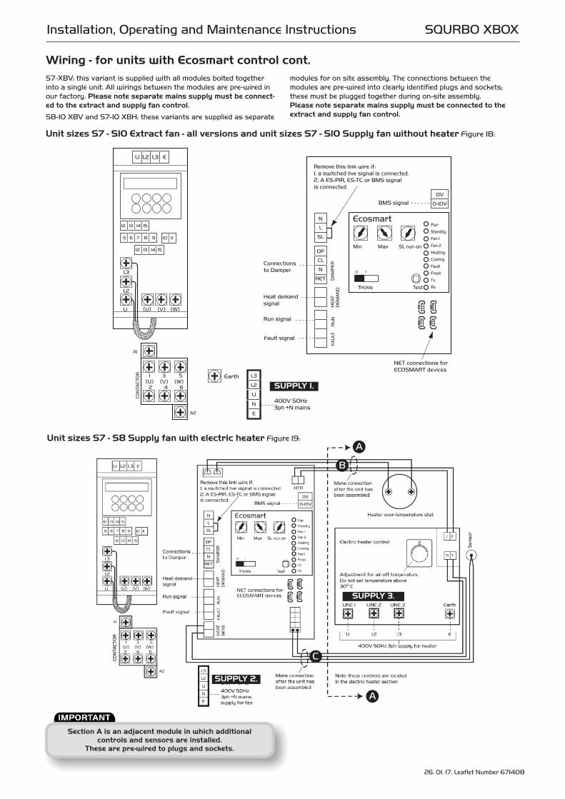
Unit sizes S7 - S10 Extract fan - all versions and unit sizes S7 - S10 Supply fan without heater Figure 18:
Unit sizes S7 - S8 Supply fan with electric heater Figure 19:
Wiring - for units with Ecosmart control cont.S7-XBV: this variant is supplied with all modules bolted togetherinto a single unit. All wirings between the modules are pre-wired inour factory. Please note separate mains supply must be connect-ed to the extract and supply fan control.
S8-10 XBV and S7-10 XBH: these variants are supplied as separate
modules for on site assembly. The connections between the modules are pre-wired into clearly identified plugs and sockets;these must be plugged together during on-site assembly. Please note separate mains supply must be connected to theextract and supply fan control.
SUPPLY 1.
Section A is an adjacent module in which additional controls and sensors are installed.
These are pre-wired to plugs and sockets.
SUPPLY 3.
SUPPLY 2.

8 26. 01. 17. Leaflet Number 671408
Installation, Operating and Maintenance Instructions SQURBO XBOX
Wiring - for units with Ecosmart control cont.
Unit sizes S7 - S10 Supply fan with LPHW coil Figure 20:
(A) Is pre-wired to plugs and sockets.
Connections to Damper
FA
ULT
R
UN
N
L
SL
DP
CL
N
RET
Remove this link wire if: 1. a switched live signal is connected.2. A ES-PIR, ES-TC or BMS signalis connected.
NET connections for ECOSMART devices
Min Max SL run on
Trickle Test
0 1
Pwr
Standby
Fan 1
Fan 2
Heating
Cooling
Fault
Frost
Tx
Rx
Ecosmart
Heat demand signal
Earth
Run signal
Fault signal
HE
AT
DA
MP
ER
DE
MA
ND
L3
L2
L1
N
E
400V 50Hz 3ph +N mains
1 3 5
2 4 6(U) (V) (W)
L1 L2 L3 E
(U) (V) (W)
L3
L2
L1
12 13 14 15
5 6 7 8 9 10 11
12 13 14 15
CO
NTA
CT
OR
A1
A2
ON
OF
F
AU
TO
HE
AT
ER
/CO
OL
Cooling demand signal
Frostalarm signal
Signal for DX1 coilif fitted
Signal for DX2 coilif fitted
25
30
25
Set air off temperature of LPHW coil
Connect to inlet sensor after unit is assembled
Outlet sensor
Inlet sensor
3
2
1
GREEN
BROWN
WHITE
Connect to LPHW actuator motor SM24motor set at position A
0V
0-10VBMS signal
A
A
9 26. 01. 17. Leaflet Number 671408
Installation, Operating and Maintenance Instructions SQURBO XBOX
Wiring - for units with Ecosmart control cont.
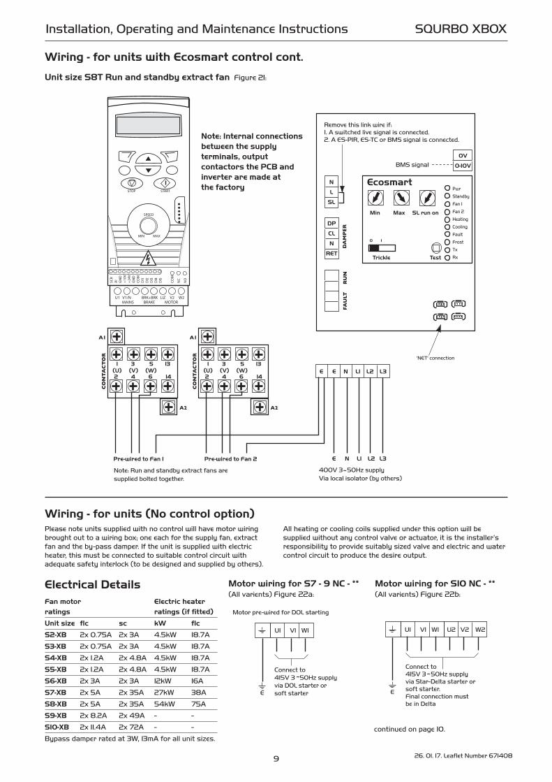
Unit size S8T Run and standby extract fan Figure 21:
FAU
LT
RU
N
N
L
SL
Remove this link wire if: 1. A switched live signal is connected.2. A ES-PIR, ES-TC or BMS signal is connected.
Min Max SL run on
Trickle Test
0 1
Pwr
Standby
Fan 1
Fan 2
Heating
Cooling
Fault
Frost
Tx
Rx
Ecosmart
D
AM
PER
E E N L1 L2 L3
400V 3~50Hz supply Via local isolator (by others)
0V
0-10VBMS signal
'NET' connection
E N L1 L2 L3
Note: Run and standby extract fans aresupplied bolted together.
DP
CL
N
RET
Note: Internal connections between the supply terminals, output contactors the PCB and inverter are made at the factory
1 3 5 13
2 4 6 14(U) (V) (W)
CON
TACT
OR
A1
A2
Pre-wired to Fan 1
1 3 5 13
2 4 6 14(U) (V) (W)
CON
TACT
OR
A1
A2
Pre-wired to Fan 2
Wiring - for units (No control option)Please note units supplied with no control will have motor wiringbrought out to a wiring box; one each for the supply fan, extractfan and the by-pass damper. If the unit is supplied with electricheater, this must be connected to suitable control circuit with adequate safety interlock (to be designed and supplied by others).
All heating or cooling coils supplied under this option will be supplied without any control valve or actuator, it is the installer’sresponsibility to provide suitably sized valve and electric and watercontrol circuit to produce the desire output.
Motor wiring for S7 - 9 NC - **(All varients) Figure 22a:
U1 V1 W1
Connect to415V 3 50Hz supplyvia DOL starter orsoft starter
Motor pre-wired for DOL starting
~
E
Motor wiring for S10 NC - ** (All varients) Figure 22b:
U1 V1 W1
Connect to415V 3 50Hz supplyvia Star-Delta starter orsoft starter.Final connection must be in Delta
~
E
U2 V2 W2
Electrical DetailsFan motor Electric heater
ratings ratings (if fitted)
Unit size flc sc kW flc
S2-XB 2x 0.75A 2x 3A 4.5kW 18.7A
S3-XB 2x 0.75A 2x 3A 4.5kW 18.7A
S4-XB 2x 1.2A 2x 4.8A 4.5kW 18.7A
S5-XB 2x 1.2A 2x 4.8A 4.5kW 18.7A
S6-XB 2x 3A 2x 3A 12kW 16A
S7-XB 2x 5A 2x 35A 27kW 38A
S8-XB 2x 5A 2x 35A 54kW 75A
S9-XB 2x 8.2A 2x 49A - -
S10-XB 2x 11.4A 2x 72A - -
Bypass damper rated at 3W, 13mA for all unit sizes.continued on page 10.

10 26. 01. 17. Leaflet Number 671408
Installation, Operating and Maintenance Instructions SQURBO XBOX
E
L1
L2
L3
Connect to 400V 3 50Hz supply via suitable control circuit
Connect over temperaturetrip to control circuit
~
E
Typical electric heater wiring S6 12kW, S7 and S8 Figure 23:
Remove the access panel on the heater sectionto gain access to the wiring point.
Isolator by others
N L
N L230V-50Hz
N L230V-50Hz
N L
Isolator by others
By
pass
Da
mpe
rP
ow
er t
o o
pen
Au
to C
lose
Ele
ctri
c H
eate
rT
her
ma
l Ove
rlo
ad
Co
nn
ecti
on
to
E
lect
ric
Ele
men
ts
Fan wiring for S2 - 6-XB withelectric heater, bypass damperand electric heater wiringFigure 26:
Fan wiring for S2 - 6-XB fan only or with LPHW coil bypassdamper wiring Figure 27:
N L230V-50Hz
Isolator by others
By
pass
Da
mpe
rP
ow
er t
o o
pen
Au
to C
lose
N L
EA
RT
H
NE
UT
RA
L
LIV
E
Isolator by others
N L
N L230V-50Hz
Fuse
3A (T)
Fan wiring for S2 - 5-XB 2 per unit and one per blowerFigure 24:
Isolator by others
N L
N L
230V-50Hz
Speed control signal<1V = fan offAlternatively connect linkfrom +V to SIG for max speed
1 - 10
V
0V
+V
SIG
0V
Note: Do not wire the power supply to motor via motor thermal overload as these are only closed after the motor is energised.Thermal overload contact rating is 2A max resistive.
Mo
tor
Th
erm
al
Ove
rlo
ad
TK TK
Fan wiring for S6-XB 2 per unit and one per blowerFigure 25:
CO
MM
ON
CLO
SE
OP
EN
Switch by others
1 2 3
N L
230V 50Hz 1 phase
Wiring for S7 - 10-XB bypassdamper Figure 28:
Wiring - for units (No control option) cont.

Where units are supplied in modular sections, sizes 6 to 10 it willalso be necessary to install data cable (supplied) between Ecosmart
controls and from Ecosmart sensors and heat exchanger etc. Some ancillary items (e.g. motorized dampers, Frost Coils) may
also require mains rated and data cable connections.
Where units form part of a larger system it will be necessary toinstall and connect mains wiring between controls and devices such as heat exchangers and motorised dampers - refer to the
relevant section of this document.Where units are supplied in modular sections it will also be
necessary to install and connect mains wiring between sensors and actuators and the main control location.
11 26. 01. 17. Leaflet Number 671408
Installation, Operating and Maintenance Instructions SQURBO XBOX
Figure 29: ‘Net’ connection forEcosmart devices.
Figure 30:
N E L SL
Remove link if switched live signal, an enabler or BMS signal is connected
Mains connection230V 50Hz 1 phase
RUN FAULT
Run signal
Fault signal
Figure 31a: Drive open/Spring close.
Figure 32:
All wiring is 1Ph 230V 50Hz
230Vmotor
S4
2
S61
OP CL N RET
All wiring is 1Ph 230V 50Hz
230Vmotor
OP CL N RET
White Brown Blue
A fan starting delay of 1 minute is imposed to enable the damper to open. To override the delay fit a link here
A fan starting delay of 1 minute is imposed to enable the damper to open. To override the delay fit a link here
Figure 31b: Drive open/Drive close.
Cooling demand signal
Frostalarm signal
Signal for DX1 coilif fitted
Signal for DX2 coilif fitted
Outlet sensor
Inlet sensor
Cool demand Frost DX1 DX2
Figure 33:
Wiring (continued)The electrical wiring must be carried out by a competent person and the unit must be provided with means of local isolation(by others) for maintenance purposes. A suitable isolator is available from Nuaire as a separate option.
Connections a) Mains connectionsMains cables should be suitably sized and terminated at terminals shown on the appropriate diagram.
b) Control connectionsThe facilities described below are provided, but may not be relevantto your installation – refer to project documentation.
Net - the 4 IDC plug-in connectors are provided for the connectionof compatible sensors, manual controls and for linking the fanstogether under a common control. If more than 4 connections arerequired, the junction box (product code ES-JB) should be used(see data cable installation).
c) Switched Live (SL) terminal
A signal of 100 - 230V a.c. will activate the fan from either its offstate or trickle state (see setting to work-trickle switch).When the SL is disconnected the fan will over-run (see setting towork-timer adjustment).
Do not take this signal from an isolating transformer.
d) Damper connections
OP - 230V 50Hz 1A max supply to open the damperCL - 230V 50Hz 1A max supply to close the damperN - Neutral supply to damperRET - 230V ac return signal from the damper limit switch indicates the damper has reached its operating position. If the return signal is not present, the fan will wait for 1 minutebefore starting. Note: If a damper is not fitted, connect a link wire from OP to RET.This will cancel the delay.
e) Volt Free Relay Contacts
Note that the volt free contacts are not fused. If these are used topower any external equipment, the installer must provide adequatefusing or other protection. These contacts are rated at 5A resistive, 0.5A inductive.
Run connections - These contacts are closed when the fan is running.
Fault connections - No fault = the contacts are closed.Fault = the contacts are opened.Heat demand - contacts closed when heating is selected.Cooling demand - contacts close when cooling selected. Do not use this contact to switch compressors directly.Frost alarm - contacts close when air off temperature is 40C orbelow. Fan shuts down, valve opens and the heat demand contactsactivated.DX1 - contacts close when stage 1 of DX coil selected.DX2 - contacts close when stage 2 of DX coil selected.
f) Data cable installationA 4-core SELV data cable is used to connect devices. Do not run data cable in the same conduit as the mains cables andensure there is a 50mm separation between the data cable andother cables. The maximum cable run between any two devices is300m when it is installed in accordance with the instructions.Please note that the total data cable length used in any systemmust be less than 1000m. Keep the number of cable joints to aminimum to ensure the best data transmission efficiencybetween devices.
g) Maximum number of devicesThe maximum number of devices (including fans) that can be connected together via the cable is 32, irrespective of their functions.
h) Other low voltage cablesKeep the cable run as short as possible, less than 50 metres.
j) BMS input signalsThe BMS connection is made with a plug-in connector via the socket (See figure 34). To ensure the connection is made only bysuitably qualified and authorised personnel the plug is not supplied. It is available from R S Components, Part No. 403-875 or Farnell,Part No. 963-021.
Reversal of the BMS connection will damage the control.

12 26. 01. 17. Leaflet Number 671408
Installation, Operating and Maintenance Instructions SQURBO XBOX
Wiring (continued)The system’s response to a 0-10V dc BMS signalis given in the table below.
Note the BMS signal will override any sensors and user control connected in the system. The voltage tolerance is +/_ 125mV and is measured at the fan’s terminal.
Ventilation mode Cooling mode* Heating mode*
Local control 0.00 - -
OFF / trickle 0.25 - -
Speed 1 0.50 0.75 1.00
Speed 2 1.50 1.75 2.00
Speed 3 2.50 2.75 3.00
Speed 4 3.50 3.75 4.00
Speed 5 4.50 4.75 5.00
Speed 6 5.50 5.75 6.00
Speed 7 6.50 6.75 7.00
Speed 8 7.50 7.75 8.00
Speed 9 8.50 8.75 9.00
Speed 10 9.50 9.75 10.00
* Only available on relevant unit.
5.0 Commissioning & Setting to work(Note – not all of the components listed here are necessarilyincluded with the equipment supplied).
5.1 Dampers (shut-off, isolation andface/bypass)Check the free action of the damper blades before powered operation (the actuator has a gear release button). Check that the actuator operates freely and over the correct range.
5.2 Mixing BoxesMixing box dampers should be checked as in 4.1 and should beadjusted / set up to give the required airflows through each leg.
5.3 FiltersRemove filter access panels (observe and note airflow directionlabels), inspect filters for contamination with construction debris,replace as necessary. Replace access panels.
Filter pressure drops will depend on actual flow rate and condition.Observe and record filter pressure drops after performance commissioning.
Typically, filter “dirty” condition occurs when the initial filter“clean” readings have been increased by 125Pa.
If filter manometers, pressure switches or indicators have been fitted, they should be set or adjusted to reflect the commissionedsystem operation.
5.4 Heating & Cooling CoilsWaterWater coils should be connected to ensure that full counter flowexists i.e. - the entering airflow meets the return connection. All water coils should be connected with the flow at the bottomand the return at the top unless otherwise advised. Drain and bleed valves are located on the coil, others may berequired in the system pipe-work depending on the installation.
Frost protection must be incorporated on shut down and fresh airconditions to avoid coil freezing. The Ecosmart control system iffitted, includes temperature sensing and frost protection strategies.
Ideally, where the system is at risk of frost damage, the additionof a proprietary anti-freeze solution to the water is recommended.
Where Ecosmart heating / cooling controls are provided, the coil is pre-fitted with a 3 / 4 port valve and actuator housed in thecasing extension.
Pipe-work connections should be made to the unit using appropriatetechniques, and must be independently supported. The connectionsshould be pressure tested.
DXDirect expansion coils must be fitted with a correctly sized thermostatic expansion valve with an external equalising connection.The expansion valve phial must be fitted between the suction header connection and the equalising line. The recommendationsof the TE valve manufacturer should be referred to when locatingthe phial and adjusting the superheat. In all cases, settings shouldbe in accordance with the recommendations of the manufacturerof the refrigeration equipment.
All cooling coil drains must be connected to the sloping drain witha correctly sized trap running to an open tundish or similar.Note: ES-TC must be used in conjunction with DX.
5.5 Electric HeatersRemove control access panel to permit site wiring to the Ecosmartheating controller, or directly to the heating elements.
Elements have threaded connection points for linking elements and site wiring. Elements should be linked with reference to theappropriate wiring diagram, and the maximum available elementpower combination may be decreased if required. Always maintaina balanced load on three phase systems.
Cable entry must be made through the apertures provided.Screwed glands with cable restraint devices should be used.
PVC or similar cables must not be used inside the heater unit –due to the temperatures that may be experienced.
Units with Ecosmart electric heating controls incorporate a fanrun-on facility and overheat / fan failure protection.
In non-Ecosmart units, heaters are fitted with an over-heat cut-outthat must be wired into the control system.
It is strongly recommended that an airflow switch is incorporatedwithin the control system with a fan run on timer (15 minutes) andan interlock provided between the heater contactor and fan motorstarter – to allow elements to cool on shutdown.
Nuaire will accept no liability for damage caused by an inadequatecontrol system.
All heaters must be wired in accordance with IEE regulations andconform to local and national statutory requirements. The element tray is a mains carrying component and must beearthed.
5.6 Recuperators (Plate heatexchangers)All recuperator drains must be connected to the drain socket andsloping drain with a correctly sized trap running to an opentundish or similar. Note that more than one drain point may be fit-ted – drain trapping must ensure isolation.
5.7 Fan SectionsAccess to the fan section is via lift off panels. Cable entry must bemade through the apertures provided. Screwed glands with cablerestraint devices should be used.
For units with Ecosmart controls, the fan motors and failure pro-tection devices are pre-wired to the control assembly.
For non-Ecosmart units, wiring to the fan motor / unit terminalbox should be mechanically protected and in made in accordancewith the details on the motor name plate and diagram attached tothe unit.
For star delta starting, all links should be removed from the motorterminal box and the motor wired as per the instructions suppliedwith starter.
With the unit electrically isolated, rotate the fan impeller / drivemanually, checking that it spins freely. Check all fixings aresecure.
Figure 34:
0 - 10
V
0V
BMS

13
Isolation - Before commencing work make sure that the unit andNuaire control are electrically isolated from the mains supply.
Warning - Inverter Speed ControlAn Inverter is used to provide speed control. When the fan is isolated, allow 5 minutes for the capacitors in the inverter to
discharge before commencing any work on the unit.
26. 01. 17. Leaflet Number 671408
Installation, Operating and Maintenance Instructions SQURBO XBOX
Units must not be operated without all access panels in place –damage to equipment or injury to personnel may result.
Units must not be operated unless control interlocks are in place –damage to equipment may result.
Test run motor for condition and correct rotation.
Check that the correct current overloads are fitted and that thecurrent being drawn does not exceed the motor nameplate value.Excessive current normally indicates that the ductwork systemresistance is different to design.
5.8 Electrical – Ecosmart UnitsCommissioning panel - Using the Test buttonThe panel is located within the control enclosure – one for eachfan.
The test button allows the fan within the unit to be checked forcorrect operation. If the fan is running already, press the buttononce to stop the fan, press again to switch on the fan.
Note that the fan will return to normal operation after 30 seconds.
LED Indication PWR GREEN: Power on & OK,
Standby LED on when fan is not running.
Fan 1 GREEN: Fan 1 is running, RED: Fan 1 faulty.
Fan 2 GREEN: Fan 2 is running, RED: Fan 2 faulty.
Heating* GREEN: Heating selected
Cooling* GREEN: Cooling selected
Fault: LED on when a fault is present on unit.
Frost* RED: Frost condition exists
Tx LED on when the controller is transmitting data.
Rx LED on when the controller is receiving data.
* Note that this control panel is common to all the NuaireEcosmart products and may have indicators for functionsthat are not available in individual units – however, the unusedindicators will not be illuminated.
5.9 SettingsSetting the maximum airflowi) Ensure the power supply is switched off and that a linkwire isconnected from the supply L to the SL terminal. Unplug all itemsconnected to the ‘Net‘ connectors.
ii) Switch on the power supply.
iii) Wait for the fan to complete its self-test operation.
Measure the airflow using standard commissioning instruments ata suitable point in the ductwork.
If adjustment is required, rotate the pot marked ‘MAX’ to obtainthe desired airflow. Remove the link wire if not required.
Setting the minimum/trickle airflow rate(Nominally 40% for S6 units and 20% for all others as standard).
i) Repeat the same procedure as for maximum airflow above butwithout the link wire between supply L and SL terminal.
Ensure the trickle switch is in the ‘ON’ position. Adjustment mustbe made on the pot marked ‘Min’.
ii) Note that the minimum setting (nominally 40%) must be belowthe maximum setting, otherwise the minimum setting will be auto-matically set to be the same as the maximum.
iii) The minimum speed set is the trickle speed at which the fanoperates.
Note: The working adjustment of the fan speed by user controland sensors, ranges between the minimum and maximum setpoints.
Note :- Where third party controls are specified and fitted, reference should be made to the control specification and operating instructions.
It is the installer’s responsibility to ensure that such controlsare suitable for operation with the Nuaire equipment.
Nuaire will accept no liability for equipment damage resultingfrom incompatible controls.
Mechanicali) Wet systems require the setting of the coil bypass balancingvalve, set using general commissioning procedures - refer to thespecified design flow duties and any documentation attached tothe valve.
6.0 MaintenanceIt is recommended that PPE is always used during the maintenanceof Air Handling Equipment – gloves, eye shields and respiratorymask.
In some Ecosmart units and in some third party controls, variablespeed drives (inverters) are used to provide fan speed control.After the fan is isolated, allow at least 5 minutes for the capacitorsin the inverter to discharge before commencing any work on theunit.
6.1 DampersAt regular intervals check that the blades move freely.
6.2 FiltersDisposable filters should be changed when fully dust laden.Washable filters should be removed when fully dust laden andwashed in mild detergent, flushed with clean water and allowed todry before replacing.
Carbon filters should be replaced once carbon activation isexhausted.
Inclined gauge manometers, where fitted, should be checked forfluid level.
6.3 Heating and Cooling CoilsCoils should have their finned surface examined for accumulationof dirt, lint and biological contaminants or similar. If necessary,wash down affected areas with a mild detergent solution and a soft brush. Care should be taken not to damage the finned surface, and any cleaning fluids should be rinsed away with water.A compressed air line may be used to blow out any solids between
LED indicators
Min Max SL run on
Trickle Test
0 1
Pwr
Standby
Fan 1
Fan 2
Heating
Cooling
Fault
Frost
Tx
Rx
Ecosmart
Co
nn
ecto
r
MIN = MAX = SL Run on =
TRICKLE =
TEST =
Minimum speed adjustmentMaximum speed adjustment Switched Live Run-On Timer adjustment Selects trickle running: 0 = off, 1 = selectedTest button
Figure 35:

14 26. 01. 17. Leaflet Number 671408
Installation, Operating and Maintenance Instructions SQURBO XBOX
fins. Do not probe the coil fin block with metal objects as damagemay cause leaks.
Drain lines should be checked to ensure that they are unobstructedand free draining. Traps should be checked that they are fullyprimed and functioning.
Drain pans should be flushed out periodically to remove contamination.
Note: The unit application may require particular attention tothis item – Check with Building Management personnel fordetails.
6.4 Electric HeatersElectric heaters should be checked at regular intervals for conditionof elements, wiring and insulation.
6.5 RecuperatorThe recuperator block is normally protected from dust and contamination by upstream pre-filters. It is possible to clean theunit with compressed air in the case of dust deposits or by sprayingwith a mild detergent solution for grease deposits. Solvents, strong alkaline, acidic or any products that may beaggressive to aluminium should not be used. Do not use cleaningwater over 50 deg C.
Drain lines should be checked to ensure that they are unobstructedand free draining. Traps should be checked that they are fullyprimed and functioning.
Drain pans should be flushed out periodically to remove contamination, and chemical treatments may be used to provideprotection between service visits.
Note: The unit application may require particular attention tothis item – Check with Building Management personnel fordetails.
6.6 Fans, Motors and Belt DrivesFan bearings should be manually checked at regular intervals forcondition. Standard fan bearings are supplied as ‘sealed for life’and have an anticipated life of 40,000 hours.
Motors have an enclosed bearing housing and are pre-greased forlife. Belts should be checked for wear, tension and alignment.Check all fixings are secure.
Checking drive belt Tension (Sizes 9 & 10)To check the correct tension of a drive belt, apply a force at rightangles to the centre of the belt span sufficient to deflect the belt16mm for every metre of span length.
The force required to deflect the ‘V’ belt should be from 0.5kg to0.8kg.
Changing a drive beltTo replace a belt, remove the two bolts from the motor mountingfurthest from the fan and slacken the remaining two bolts. Lift the motor plate and remove the belt. Replacing the belt is thereverse of this procedure.
Adjusting drive belt tension All belt drive units incorporate a belt tensioning facility.
To adjust the belt tension, slacken the pinch bolts on the sides of
the motor plate. Use the motor platform pivot adjustment to tighten and loosen the belt.
Clean impellers with a soft brush only, and remove dust/deposits from all internal surfaces including the motor housing,
6.7 GeneralInspect all internal and external surfaces to check for corrosion or peeling of painted surfaces.
Thoroughly clean affected areas with a wire brush, apply a coat of zinc rich primer or similar, and re-touch with suitable finishing paint. Ensure tightness of all nuts, bolts, and fixings. Check all components for general condition.
7.0 MaintenanceMaintenance schedule (typical – will depend on site conditions)
6 MONTHS 12 MONTHS
FILTERS 4 or 4
DAMPERS 4
DAMPER ACTUATORS 4
BELT DRIVES 4
FILTER MANOMETER FLUID 4
VENT WATER COILS 4
COIL FINNED SURFACES 4
CHECK DRAIN LINES + DRIP TRAY 4 4
CLEAN & FLUSH DRAIN PANS BuildingSchedule ? 4
NUTS, BOLTS, FIXINGS SECURE 4
FAN BEARINGS 4
ELECTRIC HEATERS 4
ELECTRICAL WIRING 4
FAN IMPELLER 4
GENERAL 4
8.0 WarrantyEcosmart SQURBO XBOX units have a 5 year warranty. No control units have a 2 year warranty. The first year covers parts and labour and the remaining period covers parts only.
This warranty is void if the equipment is modified without authorisation, is incorrectly applied, misused, disassembled, or not installed, commissioned and maintained in accordance with the details contained in this manual and general good practice.
The product warranty applies to the UK mainland and in accordance with Clause 14 of our Conditions of Sale. Customers purchasing from outside of the UK should contact Nuaire International Sales office for further details.
9.0 After Sales EnquiriesFor technical assistance or further product information, including spare parts and replacement components, please contact the After Sales Department.
Telephone 02920 858 400
Figure 36:

15 26. 01. 17. Leaflet Number 671408
Technical or commercial considerations may, from time to time, make it necessary to alter the design, performance and dimensions of equipment and the right is reserved to make such changes without prior notice.
DECLARATION OF INCORPORATION AND INFORMATION FOR SAFE INSTALLATION, OPERATION AND MAINTENANCE
To comply with EC Council Directives 2006/42/EC Machinery Directive and 2014/30/EU (EMC).
To be read in conjunction with the relevant Product Documentation (see 2.1)
1.0 GENERAL
1.1 The equipment referred to in this Declaration of Incorporation is supplied by Nuaire to be assembled into a ventilation system which may or may not include additional components.
The entire system must be considered for safety purposes and it is the responsibility of the installer to ensure that all of the equipment is installed in compliance with the manufacturers recommendations and with due regard to current legislation and codes of practice.
2.0 INFORMATION SUPPLIED WITH THE EQUIPMENT
2.1 Each item of equipment is supplied with a set of documentation which provides the information required for the safe installation and maintenance of the equipment. This may be in the form of a Data sheet and/or Installation and Maintenance instruction.
2.2 Each unit has a rating plate attached to its outer casing. The rating plate provides essential data relating to the equipment such as serial number, unit code and electrical data. Any further data that may be required will be found in the documentation. If any item is unclear or more information is required, contact Nuaire.
2.3 Where warning labels or notices are attached to the unit the instructions given must be adhered to.
3.0 TRANSPORTATION, HANDLING AND STORAGE
3.1 Care must be taken at all times to prevent damage to the equipment. Note that shock to the unit may result in the balance of the impeller being affected.
3.2 When handling the equipment, care should be taken with corners and edges and that the weight distribution within the unit is considered. Lifting gear such as slings or ropes must be arranged so as not to bear on the casing.
3.3 Equipment stored on site prior to installation should be protected from the weather and steps taken to prevent ingress of contaminants.
4.0 OPERATIONAL LIMITS
4.1 It is important that the specified operational limits for the equipment are adhered to e.g. operational air temperature, air borne contaminants and unit orientation.
4.2 Where installation accessories are supplied with the specified equipment eg. wall mounting brackets. They are to be used to support the equipment only. Other system components must have separate provision for support.
4.3 Flanges and connection spigots are provided for the purpose of joining to duct work systems. They must not be used to support the ductwork.
5.0 INSTALLATION REQUIREMENTS
In addition to the particular requirements given for the individual product, the following general requirements should be noted.
5.1 Where access to any part of equipment which moves, or can become electricallylive are not prevented by the equipment panels or by fixed installation detail (eg ducting), then guarding to the appropriate standard must be fitted.
5.2 The electrical installation of the equipment must comply with the requirements of the relevant local electrical safety regulations.
5.3 For EMC all control and sensor cables should not be placed within 50mm or on the same metal cable tray as 230V switched live, lighting or power cables and any cables not intended for use with this product.
6.0 COMMISSIONING REQUIREMENTS
6.1 General pre-commissioning checks relevant to safe operation consist of the following:
Ensure that no foreign bodies are present within the fan or casing.
Check electrical safety. e.g. Insulation and earthing.
Check guarding of system.
Check operation of Isolators/Controls.
Check fastenings for security.
6.2 Other commissioning requirements are given in the relevant product documentation.
7.0 OPERATIONAL REQUIREMENTS
7.1 Equipment access panels must be in place at all times during operation of the unit, and must be secured with the original fastenings.
7.2 If failure of the equipment occurs or is suspected then it should be taken out of service until a competent person can effect repair or examination. (Note that certain ranges of equipment are designed to detect and compensate for fan failure).
8.0 MAINTENANCE REQUIREMENTS
8.1 Specific maintenance requirements are given in the relevant product documentation.
8.2 It is important that the correct tools are used for the various tasks required.
8.3 If the access panels are to be removed for any reason the electrical supply to the unit must be isolated.
8.4 A minium period of two minutes should be allowed after electrical disconnection before access panels are removed. This will allow the impeller to come to rest.
NB: Care should still be taken however since airflow generated at some other point in the system can cause the impeller to “windmill” even when power is not present.
8.5 Care should be taken when removing and storing access panels in windy conditions.
INFORMATION FOR SAFE INSTALLATION, OPERATION AND MAINTENANCE OF NUAIRE VENTILATION EQUIPMENT
We declare that the machinery named below is intended to be assembledwith other components to constitute a system of machinery. All parts except for moving parts requiring the correct installation of safety guardscomply with the essential requirements of the Machinery Directive. The machinery shall not be put into service until the system has been declared to be in conformity with the provisions of the EC Machinery Directive.
Designation of machinery: SQURBO XBOX
Machinery Types: Supply & Extract Fans with Heat Recovery
Relevant EC Council Directives: 2006/42/EC (Machinery Directive)
Applied Harmonised Standards: BS EN ISO 12100-1, BS EN ISO 12100-2, EN60204-1, BS EN ISO 9001, BS EN ISO 13857
Applied National Standards: BS848 Parts 1, 2.2 and 5
Note: All standards used were current and valid at the date of signature.
Signature of manufacture representatives:Name: Position: Date:
1) C. Biggs Technical Director 26. 01. 11
2) A. Jones Manufacturing Director 26. 01. 11

16 26. 01. 17. Leaflet Number 671408
Western Industrial Estate
Caerphilly United Kingdom
CF83 1NA
T: 029 2085 8400
F: 029 2085 8444
W: www.nuaire.co.uk
Installation, Operating and Maintenance Instructions SQURBO XBOX
Related Documents