llustrations The Transfer Function of Linear Systems V 1 s () R 1 Cs Is () Z 1 s () R Z 2 s () 1 Cs V 2 s () 1 Cs Is () V 2 s () V 1 s () 1 Cs R 1 Cs Z 2 s () Z 1 s () Z 2 s ()

Illustrations The Transfer Function of Linear Systems.
Dec 22, 2015
Welcome message from author
This document is posted to help you gain knowledge. Please leave a comment to let me know what you think about it! Share it to your friends and learn new things together.
Transcript

Illustrations
The Transfer Function of Linear Systems
V1 s( ) R1
Cs
I s( ) Z1 s( ) R
Z2 s( )1
CsV2 s( )1
Cs
I s( )
V2 s( )
V1 s( )
1
Cs
R1
Cs
Z2 s( )
Z1 s( ) Z2 s( )

Illustrations
The Transfer Function of Linear Systems
Example 2.2
2ty t( )d
d
24
ty t( )d
d 3 y t( ) 2 r t( )
Initial Conditions: Y 0( ) 1ty 0( )d
d0 r t( ) 1
The Laplace transform yields:
s2 Y s( ) s y 0( ) 4 s Y s( ) y 0( )( ) 3Y s( ) 2 R s( )
Since R(s)=1/s and y(0)=1, we obtain:
Y s( )s 4( )
s2 4s 3 2
s s2 4s 3
The partial fraction expansion yields:
Y s( )
3
2
s 1( )
12
s 3( )
1s 1( )
1
3
s 3( )
2
3
s
Therefore the transient response is:
y t( )3
2e t
1
2e 3 t
1 e t 1
3e 3 t
2
3
The steady-state response is:
ty t( )lim
2
3

Illustrations
The Transfer Function of Linear Systems
i
o
i
o
i
o
Z
Z
V
V
R
R
IR
IR
V
V
1
2
1
2

Illustrations
The Transfer Function of Linear Systems

Illustrations
)/)(/1(/1/1
1
/1/1
/10
0
/1
0
00
/1
0
121121
1
21
1
1
22
2
2
1
21
1
12
2
1
1
1
vvRRRsCr
v
LssCR
R
v
v
Ls
v
sC
v
R
vv
R
vv
R
v
sC
vr

Illustrations
R
XFind
))((
1
R
X
))(()(
)(
)(
)(
)(
2
1122
12
1
2
1122
12
121212
211
12
112112
1112112
21
2
1
1
12
2
2
1
22
22112
222112
22
2
2
sbsbsbsMX
X
sbsbsbsMX
XXsbXsbsbsMXR
XsMRsXsXbsXb
xMRxxbxb
dt
xdMF
sb
sbksM
X
X
XsMsXsXbkX
xMxxbkxdt
xdMF

Illustrations
The Transfer Function of Linear Systems

Illustrations
The Transfer Function of Linear Systems

Illustrations
Kf if
Tm K1 Kf if t( ) ia t( )
field controled motor - Lapalce Transform
Tm s( ) K1 Kf Ia If s( )
Vf s( ) Rf Lf s If s( )
Tm s( ) TL s( ) Td s( )
TL s( ) J s2 s( ) b s s( )
rearranging equations
TL s( ) Tm s( ) Td s( )
Tm s( ) Km If s( )
If s( )Vf s( )
Rf Lf s
The Transfer Function of Linear Systems
Td s( ) 0
s( )
Vf s( )
Km
s J s b( ) Lf s Rf
Ia = constant, controlling using if
2
)(
JsBsTT
JBTTF
JsBwJswBwTT
wJBwTT
wJBwTT
wJJJT
dm
dm
dm
dm
dm
BsJs
k
sLRTI
Tm
v
I
vm
ffmff
f
f
2
1*
1*
1**

Illustrations
The Transfer Function of Linear Systems

Illustrations
The Transfer Function of Linear Systems

Illustrations
The Transfer Function of Linear Systems

Illustrations
The Transfer Function of Linear Systems

Illustrations
The Transfer Function of Linear Systems
V 2 s( )
V 1 s( )
1RCs
V 2 s( )
V 1 s( )RCs

Illustrations
The Transfer Function of Linear Systems
V 2 s( )
V 1 s( )
R 2 R 1 C s 1 R 1
V 2 s( )
V 1 s( )
R 1 C 1 s 1 R 2 C 2 s 1 R 1 C 2 s

Illustrations
The Transfer Function of Linear Systems
s( )
V f s( )
K m
s J s b( ) L f s R f
s( )
V a s( )
K m
s R a L a s J s b( ) K b K m

Illustrations
The Transfer Function of Linear Systems
Vo s( )
Vc s( )
K
Rc Rq
s c 1 s q 1
c
Lc
Rc
q
Lq
Rq
For the unloaded case:
id 0 c q
0.05s c 0.5s
V12 Vq V34 Vd
s( )
Vc s( )
Km
s s 1
J
b m( )
m = slope of linearized torque-speed curve (normally negative)

Illustrations
The Transfer Function of Linear SystemsY s( )
X s( )
K
s Ms B( )
KA kx
kp
B bA2
kp
kxx
gd
dkp
Pgd
dg g x P( ) flow
A = area of piston
Gear Ratio = n = N1/N2
N2 L N1 m
L n m
L n m

Illustrations
The Transfer Function of Linear Systems
V2 s( )
V1 s( )
R2
R
R2
R1 R2
R2
R
max
V2 s( ) ks 1 s( ) 2 s( ) V2 s( ) ks error s( )
ks
Vbattery
max
Illustrations
The Transfer Function of Linear Systems
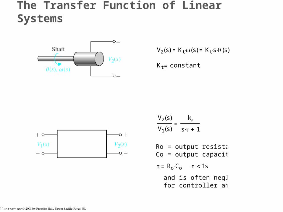
V2 s( ) Kt s( ) Kt s s( )
Kt constant
V2 s( )
V1 s( )
ka
s 1
Ro = output resistanceCo = output capacitance
Ro Co 1s
and is often negligible for controller amplifier

Illustrations
The Transfer Function of Linear Systems
T s( )
q s( )
1
Ct s Q S1
R
T To Te = temperature difference due to thermal process
Ct = thermal capacitance= fluid flow rate = constant= specific heat of water= thermal resistance of insulation= rate of heat flow of heating element
QSRt
q s( )
xo t( ) y t( ) xin t( )
Xo s( )
Xin s( )
s2
s2 b
M
sk
M
For low frequency oscillations, where n
Xo j Xin j
2
k
M

Illustrations
The Transfer Function of Linear Systems
x r
converts radial motion to linear motion

Illustrations
Block Diagram Models

Illustrations
Block Diagram Models

Illustrations
Block Diagram Models
Original Diagram Equivalent Diagram
Original Diagram Equivalent Diagram

Illustrations
Block Diagram Models
Original Diagram Equivalent Diagram
Original Diagram Equivalent Diagram

Illustrations
Block Diagram Models
Original Diagram Equivalent Diagram
Original Diagram Equivalent Diagram

Illustrations
Block Diagram Models
GH
G
R
Y
YGYHR
1
)(

Illustrations
Block Diagram Models
Example 2.7
431322432131
4321
43)1)2)2)4/()1)3(((((
GGHGGHGGGGH
GGGG
R
Y
YGGYHGHGYGYHR
..)21(1( LiLjLkiLjLLL
PD
R
Y

Illustrations
Block Diagram Models Example 2.7

Illustrations
Signal-Flow Graph Models
For complex systems, the block diagram method can become difficult to complete. By using the signal-flow graph model, the reduction procedure (used in the block diagram method) is not necessary to determine the relationship between system variables.

Illustrations
Signal-Flow Graph Models
Y1 s( ) G11 s( ) R1 s( ) G12 s( ) R2 s( )
Y2 s( ) G21 s( ) R1 s( ) G22 s( ) R2 s( )

Illustrations
Signal-Flow Graph Models
a11 x1 a12 x2 r1 x1
a21 x1 a22 x2 r2 x2

Illustrations
Signal-Flow Graph Models
Example 2.8
Y s( )
R s( )
G 1 G 2 G 3 G 4 1 L 3 L 4 G 5 G 6 G 7 G 8 1 L 1 L 2
1 L 1 L 2 L 3 L 4 L 1 L 3 L 1 L 4 L 2 L 3 L 2 L 4
..)21(1( LiLjLkiLjLLL
PD
R
Y

Illustrations
Signal-Flow Graph Models
Example 2.10
db
ab
dd
aa
TGGks
GV
GGks
GG
TT
VV
21
2
21
21
1
1
1
1

Illustrations

Illustrations
Signal-Flow Graph Models
Y s( )
R s( )
P1 P2 2 P3
P1 G1 G2 G3 G4 G5 G6 P2 G1 G2 G7 G6 P3 G1 G2 G3 G4 G8
1 L1 L2 L3 L4 L5 L6 L7 L8 L5 L7 L5 L4 L3 L4
1 3 1 2 1 L5 1 G4 H4

Illustrations
Design Examples

Illustrations
Speed control of an electric traction motor.
Design Examples

Illustrations
Design Examples

Illustrations
Design Examples

Illustrations
Design Examples

Illustrations
Design Examples

Illustrations
The Simulation of Systems Using MATLAB

Illustrations
The Simulation of Systems Using MATLAB

Illustrations
The Simulation of Systems Using MATLAB

Illustrations
The Simulation of Systems Using MATLAB

Illustrations
The Simulation of Systems Using MATLAB

Illustrations
The Simulation of Systems Using MATLAB

Illustrations
The Simulation of Systems Using MATLAB

Illustrations
The Simulation of Systems Using MATLAB

Illustrations
The Simulation of Systems Using MATLAB

Illustrations
The Simulation of Systems Using MATLAB

Illustrations
The Simulation of Systems Using MATLAB

Illustrations
The Simulation of Systems Using MATLAB

Illustrations
The Simulation of Systems Using MATLAB

Illustrations
The Simulation of Systems Using MATLAB

Illustrations
The Simulation of Systems Using MATLAB

Illustrations
The Simulation of Systems Using MATLAB

Illustrations
error
The Simulation of Systems Using MATLAB
Sys1 = sysh2 / sysg4

Illustrations
The Simulation of Systems Using MATLAB

Illustrations
error
The Simulation of Systems Using MATLAB
Num4=[0.1];

Illustrations
The Simulation of Systems Using MATLAB

Illustrations
The Simulation of Systems Using MATLAB

Illustrations
Sequential Design Example: Disk Drive Read System

Illustrations
Sequential Design Example: Disk Drive Read System

Illustrations
=
Sequential Design Example: Disk Drive Read System

Illustrations
P2.11

Illustrations
1
L c s R c
Vc
Ic
K1
1
L q s R q
Vq
K2
K3-Vb
+Vd
Km
Id
1
L d L a s R d R a
Tm
1
J s b
1
s
P2.11

Illustrations

Illustrations
http://www.jhu.edu/%7Esignals/sensitivity/index.htm

Illustrations
http://www.jhu.edu/%7Esignals/
Related Documents


