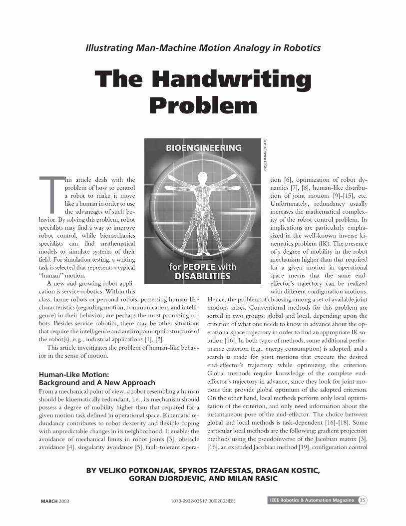
T his article deals with the problem of how to control a robot to make it move like a human in order to use the advantages of such be- havior. By solving this problem, robot specialists may find a way to improve robot control, while biomechanics specialists can find mathematical models to simulate systems of their field. For simulation testing, a writing task is selected that represents a typical “human” motion. A new and growing robot appli- cation is service robotics. Within this class, home robots or personal robots, possessing human-like characteristics (regarding motion, communication, and intelli- gence) in their behavior, are perhaps the most promising ro- bots. Besides service robotics, there may be other situations that require the intelligence and anthropomorphic structure of the robot(s), e.g., industrial applications [1], [2]. This article investigates the problem of human-like behav- ior in the sense of motion. Human-Like Motion: Background and A New Approach From a mechanical point of view, a robot resembling a human should be kinematically redundant, i.e., its mechanism should possess a degree of mobility higher than that required for a given motion task defined in operational space. Kinematic re- dundancy contributes to robot dexterity and flexible coping with unpredictable changes in its neighborhood. It enables the avoidance of mechanical limits in robot joints [3], obstacle avoidance [4], singularity avoidance [5], fault-tolerant opera- tion [6], optimization of robot dy- namics [7], [8], human-like distribu- tion of joint motions [9]-[15], etc. Unfortunately, redundancy usually increases the mathematical complex- ity of the robot control problem. Its implications are particularly empha- sized in the well-known inverse ki- nematics problem (IK). The presence of a degree of mobility in the robot mechanism higher than that required for a given motion in operational space means that the same end- effector’s trajectory can be realized with different configuration motions. Hence, the problem of choosing among a set of available joint motions arises. Conventional methods for this problem are sorted in two groups: global and local, depending upon the criterion of what one needs to know in advance about the op- erational space trajectory in order to find an appropriate IK so- lution [16]. In both types of methods, some additional perfor- mance criterion (e.g., energy consumption) is adopted, and a search is made for joint motions that execute the desired end-effector’s trajectory while optimizing the criterion. Global methods require knowledge of the complete end- effector’s trajectory in advance, since they look for joint mo- tions that provide global optimum of the adopted criterion. On the other hand, local methods perform only local optimi- zation of the criterion, and only need information about the instantaneous pose of the end-effector. The choice between global and local methods is task-dependent [16]-[18]. Some particular local methods are the following: gradient projection methods using the pseudoinverse of the Jacobian matrix [3], [16], an extended Jacobian method [19], configuration control MARCH 2003 IEEE Robotics & Automation Magazine 35 1070-9932/03$17.00©2003IEEE BY VELJKO POTKONJAK, SPYROS TZAFESTAS, DRAGAN KOSTIC, GORAN DJORDJEVIC, AND MILAN RASIC Illustrating Man-Machine Motion Analogy in Robotics The Handwriting Problem 2001 IMAGESTATE

Welcome message from author
This document is posted to help you gain knowledge. Please leave a comment to let me know what you think about it! Share it to your friends and learn new things together.
Transcript
This article deals with theproblem of how to controla robot to make it movelike a human in order to usethe advantages of such be-
havior. By solving this problem, robotspecialists may find a way to improverobot control, while biomechanicsspecialists can find mathematicalmodels to simulate systems of theirfield. For simulation testing, a writingtask is selected that represents a typical“human” motion.
A new and growing robot appli-cation is service robotics. Within thisclass, home robots or personal robots, possessing human-likecharacteristics (regarding motion, communication, and intelli-gence) in their behavior, are perhaps the most promising ro-bots. Besides service robotics, there may be other situationsthat require the intelligence and anthropomorphic structure ofthe robot(s), e.g., industrial applications [1], [2].
This article investigates the problem of human-like behav-ior in the sense of motion.
Human-Like Motion:Background and A New ApproachFrom a mechanical point of view, a robot resembling a humanshould be kinematically redundant, i.e., its mechanism shouldpossess a degree of mobility higher than that required for agiven motion task defined in operational space. Kinematic re-dundancy contributes to robot dexterity and flexible copingwith unpredictable changes in its neighborhood. It enables theavoidance of mechanical limits in robot joints [3], obstacleavoidance [4], singularity avoidance [5], fault-tolerant opera-
tion [6], optimization of robot dy-namics [7], [8], human-like distribu-tion of joint motions [9]-[15], etc.Unfortunately, redundancy usuallyincreases the mathematical complex-ity of the robot control problem. Itsimplications are particularly empha-sized in the well-known inverse ki-nematics problem (IK). The presenceof a degree of mobility in the robotmechanism higher than that requiredfor a given motion in operationalspace means that the same end-effector’s trajectory can be realizedwith different configuration motions.
Hence, the problem of choosing among a set of available jointmotions arises. Conventional methods for this problem aresorted in two groups: global and local, depending upon thecriterion of what one needs to know in advance about the op-erational space trajectory in order to find an appropriate IK so-lution [16]. In both types of methods, some additional perfor-mance criterion (e.g., energy consumption) is adopted, and asearch is made for joint motions that execute the desiredend-effector’s trajectory while optimizing the criterion.Global methods require knowledge of the complete end-effector’s trajectory in advance, since they look for joint mo-tions that provide global optimum of the adopted criterion.On the other hand, local methods perform only local optimi-zation of the criterion, and only need information about theinstantaneous pose of the end-effector. The choice betweenglobal and local methods is task-dependent [16]-[18]. Someparticular local methods are the following: gradient projectionmethods using the pseudoinverse of the Jacobian matrix [3],[16], an extended Jacobian method [19], configuration control
MARCH 2003 IEEE Robotics & Automation Magazine 351070-9932/03$17.00©2003IEEE
BY VELJKO POTKONJAK, SPYROS TZAFESTAS, DRAGAN KOSTIC,GORAN DJORDJEVIC, AND MILAN RASIC
Illustrating Man-Machine Motion Analogy in Robotics
The HandwritingProblem
20
01IM
AG
ES
TA
TE
[20], Lyapunov function-based methods [21], the distributedpositioning (DP) concept [9]-[15], inverse kinematic function[22], [23], and resolved motion [24].
Papers [9]-[14] and especially [15] offer a possibility toachieve human-like motion of a robot arm. The DP conceptis formulated in analogy to human behavior. The idea is toseparate the required motion of the end-effector in two com-ponents: one smooth (with very low accelerations) and theother highly accelerated. At the same time, the robot joints areseparated into two groups: the first corresponding to thehigh-inertia nonredundant part of the robot and the othergroup containing low-inertia redundancy. The distribution ofthe original end-effector motion is made so that the high iner-tial nonredundant part implements the smooth componentwhile the low-inertial redundancy is responsible for the accel-erated component. In the original DP concept [15], a measureof joint involvement, called kinematic fatigue, was intro-duced. We shall employ this concept and use the term integralkinematic involvement (IKI).
This article suggests a new local method for redundancyresolution that leads to human-like motions of robot joints.The method is particularly suitable to model and control thearm in the presence of fatigue.
By imitating the movements of a human arm, robot perfor-mance can be substantially improved. However, the benefitsof human-like motion cannot be gained without an under-standing of the principles that the central nervous system(CNS) employs during the generation of arm movements[25]. Unfortunately, a thorough explanation of these princi-ples is not yet available [26]. In this article, we rely on the hy-pothesis presented in [27] and suggest its application inrobotics. This hypothesis suggests that it is possible to associatesome cost function to each human arm joint. The human armperforms movements that optimize these cost functions. Ex-amples of dynamic cost functions are the following: quadraticnorm of joints control torques [8], kinetic energy [28], jerks injoints (third time derivative of joint position) [29]. Severalneurophysiological and psychophysical cost functions werealso suggested [30]: the “input energy” was defined as a qua-dratic norm of input neural signals of motor units (muscles),while the “input fatigue” denotes the magnitude of such neu-ral signals. In [30], some proper combination of these func-tions is suggested, rather than their separate application. Here,special attention is paid to functions of joints “discomfort,”
which were experimentally derived to identify arm postures ofmaximum comfort [27].
Practical experience shows that the human arm commonlytakes those postures and executes those movements that arethe most comfortable. The term “comfortable” relates to jointpositions and the engagement of motor units, which may alsobe described by the term “pleasant” (a more precise definitionwill be given later). On the other hand, endurance contrac-tions of motor units cause muscle fatigue, thus introducing anunpleasant feeling (i.e., a sense of discomfort). In everyday life,it is easy to observe that, after the sensation of discomfortcaused by muscle fatigue, the human arm normally reducesengagement of fatigued motor units by taking postures that re-quire lower participation of these units. The ability tore-arrange its motions is enabled by the existence of both theactuator and the kinematic redundancy in the human arm[31]. Actuator redundancy comes from the possibility of usingseveral motor units for the same movement of any arm joint.Kinematic redundancy results from the existence of seven de-grees of freedom (DOF) in arm joints (from shoulder to wrist),which is higher than the six independent movements requiredfor an arbitrary positioning and orientation of an object in op-erational space [15], [21]. Here, our focus will be on the kine-matic redundancy and the possibility to distribute theengagement of robot joints in a human-like fashion, imitatingthe arm’s inherent property to execute comfortable motions.The main objective is to achieve human-like motion of therobot. A result strongly correlated with our work deals withpsychophysical cost functions of joint comfort/discomfort[27]. Their validity was practically justified for arm reach pos-ture prediction in [32]. A psychophysical cost function de-scribes the deviations of joint position from the location ofmaximum comfort. Physiological and psychophysical investi-gations indicated that, in the absence of muscle fatigue, themore comfortable joint pose is closer to the middle of thephysiological range of motion in that joint.
Mathematical functions representing current distancesfrom middle positions of robot joints [3], [33], will be usedhere as a starting point for the formulation of an analytic pro-cedure to form robot joints movements that are equivalent tothe movements of a human arm after the appearance of dis-comfort due to muscle fatigue.
Muscle fatigue can be quantified by means of objective andsubjective methods. Objective methods include mechanical,electromyographic, metabolic, and physiological measure-ments [34]. Subjective methods are based on subjective evalu-ation of the sensed fatigue level given by subjects participatingin experiments [35]. No matter which method is applied forfatigue indication, it seems reasonable to consider fatigue as anincreasing function [36]. This function is often assumed tohave an exponential form [37]-[39]. The slope of the functiondepends on the actual engagement of motor units and the cur-rent level of fatigue [40].
On this basis, a mathematical nondimensional variable,called virtual fatigue (VF) of robot actuators, will be used as an
MARCH 2003IEEE Robotics & Automation Magazine36
The benefits of human-like motioncannot be gained without anunderstanding of the principlesthat the central nervous systememploys during the generation ofarm movements.
analog to the biological fatigue. Its temporal evolution isequivalent to the functional variation of biological fatigue andcan be used for the generation of human-like motions of robotjoints. When the VF in a joint reaches the prescribed criticallevel (where the joint “feels” fatigue), the motion in this jointshould be depressed to allow the motor unit to relax. Redistri-bution of motion that forces a higher engagement of otherjoints is needed. A model of VF will be derived based on thethermal-dynamics model of dc motors.
Robot Arm Kinematics and DynamicsA robot arm with n DOF is described by means of n joint co-ordinates (internal or configuration coordinates). Each coordi-nate corresponds to one joint and represents the relativemotion of the neighboring links. For the jth joint, the coordi-nate is qj. The vector q = [q1...qn]
T is called the internal positionvector, the vector of joints’ positions, or the configurationvector.
From the robot task point of view, one is concerned withthe motion of the end-effector (i.e., the terminal link of thechain including the tool for a particular operation, like aspray-gun or gripper). The spatial motion of the end-effectorcan be described by the “external coordinates”: i.e., threeCartesian coordinates of the end-effector tip (x, y, z) and threeorientation angles ( : jaw, : pitch, : roll). The vector x = [xy z θ ϕ Ψ]T] is called the vector of external position. Anotherimportant concept is the concept of operational frame or op-erational space. It denotes the subset of external positions thatcontains those coordinates that are responsible for the execu-tion of a given task. Let m be the dimension of this frame.
If m = n, the robot is nonredundant. If m < n, we talk abouta redundant robot. The arm has more DOF than needed toexecute the task. It means that the arm can move in differentways, still following the required trajectory of the end-effector in the operational frame. In some cases, this ability isused to avoid obstacles in the working space and sometimesfor the minimization of a certain cost function. Usually the mjoints with the highest inertia are considered as the “non-redundant basic configuration,” and the remaining n − mjoints as the “redundancy.”
After introducing redundancy, the problem that naturallyarises is the calculation of x for given q (direct kinematics), andvice versa (inverse kinematics). The relation between x and qis expressed by means of Jacobian forms of the first and secondorder
( ) ( ) ( )& &; && && , & ,x J q q x J q q K q q= = + (1)
where J x= ∂ /∂q is the Jacobian matrix of dimension m × n,
and K x= ∂ 2 /∂q q2 2& is the adjoint vector. The inverse kine-matics requires the solution of a system of equations with un-knowns. For nonredundant robots (m = n), a unique solutionis possible, but, for redundant robots (m < n), there is an infi-nite number of solutions. As explained earlier, one solution
may be selected from the infinite number of possible solutions,by posing some additional requirements that “employ” redun-dancy. Two approaches that lead to human-like motion of arobot arm will be presented later in this article.
Robot arm dynamics are described by the well-knownmodel:
( ) ( )H q q h q q&& , & ,+ = τ (2)
where τ is the n × 1 vector or driving torques/forces actingupon the robot joints. Joint drives are produced by some actu-ators (e.g., dc motors). The dynamics of the motor that drivesthe joint j are described by:
u r i L di dt C N q
C i I N q B N q
j j j j j Ej j j
Mj j j j j j j j j
= + +
= + +
& ,
&& & τ N j , (3)
where uj is the input control voltage, ij is the current in motorwinding, rj and Lj are resistance and inductivity, CEj and CMj areconstants of back electromotive force (EMF) and torque, Ij isthe rotor moment of inertia, Bj is the viscous friction coeffi-cient, and Nj is the joint transmission ratio. The complete dy-namics of the robot arm are defined by (2) and (3) for j =1,...,n.
DP for a Redundant Robot ArmDP is formulated in analogy with human behavior and is in-tended to model a robot arm involved in fast manipulation[9]-[14]. Redundancy is added to the basic nonredundantconfiguration in order to allow the execution. The idea is toseparate the required motion of the end-effector in two com-ponents: a smooth (low accelerated) component and a highlyaccelerated component. At the same time, the robot joints areseparated into two groups: one group of joints representingthe high-inertia nonredundant part of the robot and the othergroup containing the low-inertia redundancy. The distribu-tion of the original end-effector motion is made such that thehigh-inertia nonredundant part realizes the smooth compo-nent, while the low-inertia redundancy is responsible for theaccelerated component.
Consider a motion task that is given in terms of an m-di-mensional operational vector x(t). It is a reasonable assumptionthat only some of the x-components (ma of them) are highlyaccelerated, while the remaining m − ma components aresmooth. Let x1 be the subvector containing the acceleratedmotions (dimension ma) and x2 the subvector containing thesmooth motions (dimension m − ma). Now, [x = x1, x2]
T.It is assumed that the nonredundant arm cannot perform
the task due to high inertial loads. For a successful solution,the arm needs to have n DOF with n ≥ m + ma. This meansthat the arm must be redundant with redundancy dimen-sion nr ≥ ma. The redundant arm (with n DOF) is now sepa-rated into two subsystems. The subsystem of the m DOFwith the greater inertias is called the “basic configuration.”
MARCH 2003 IEEE Robotics & Automation Magazine 37
The other subsystem is the “redundancy,” having nr DOF. Itholds that n = m + nr. The vector of configuration coordinates isnow separated into two subvectors, as q = [qb, qr]
T, where them-dimensional vector qb corresponds to the basic configuration,and the nr-dimensional qr vector corresponds to the redundancy.
The DP concept solves the inverse kinematics of a redun-dant robot in two steps. At the first step, the motion of the ba-sic configuration is computed (qb), and, at the second step, themotion of the redundancy (qr) is determined.
Step 1: The smoothing method separates the motion x1(t)into two addenda, as
( ) ( ) ( )x x x1 1 1t t t= + ~ , (4)
where x1 represents the smooth component and ~x1 the accel-erated one. The basic operational motion xb is defined to bethe motion that contains the smoothed component of x1 andthe subvector x2 (being already smooth): i.e., xb = [~x1 , x2]
T.
Since the basic operational xb(t) motion is smooth, we forcethe basic configuration qb to solve it without the help of re-dundancy. In this case, the kinematic model model (1) be-comes the basic kinematic model that allows the calculation ofthe basic configuration motion qb(t). This calculation involvesthe inverse of a quadratic Jacobian.
Step 2: The motion of basic joints qb(t), calculated in Step 1,is now used to determine the motion of the redundancy (qr).The kinematic model (1) now acquires a reduced form calledthe kinematic model of redundancy. This model has the di-mension of ma. Since the dimension of the configuration vec-tor of the redundancy (qr) is nr > ma (equality holds in specialcases only), the motion of the redundancy cannot be com-puted. This means that Step 2 does not resolve the problem ofredundancy completely, but only partially. The degree of re-dundancy is reduced (from nr to nr − ma), but it is still present.
Now, some additional requirements have to be defined(e.g., minimization of some cost function or some special dis-tribution between joint motions) in order to employ the restof the redundancy. Mathematically, this can be expressed by apseudoinverse of the nonquadratic Jacobian in the kinematicmodel of redundancy. Finally, the motion of the redundancyis calculated, thus, the inverse kinematics is solved.
The problem that has not been elaborated in this section isthe question of smoothing. For a human, it is the problem oflearning and skill. With a robot arm, smoothing means somekind of offline or online filtering (low-pass filter).
In the redundancy that remains after Step 1, there are stilldifferent joint roles. Some joints are designed to support veryprecise but not fast motion (like in human fingers) while otherjoints may perform fast motion for long time (the role of hu-man wrist). An appropriate distribution among joint motionsmay be achieved in the robot by using the pseudoinverse asexplained above. Now, it appears necessary to introduce somemeasure of the involvement of the robot joints. This measureis the IKI or kinematic fatigue. It should take into account theamplitudes of the motion of the robot joints. Normalization tothe interval [0, 100] is made. The differential kinematic in-volvement (DKI), being the rate of IKI at a particular time in-stant, describes the current kinematic involvement.
The Concept of Virtual FatigueThis concept resembles the physical fatigue of the human armand will be used to force motion redistribution of the robotjoints when a certain joint “feels” fatigue.
Redundancy ResolutionRedundancy results in a nonunique IK solution, since a givenmotion task, defined in terms of operational velocities &x(t), canbe accomplished with infinitely many combinations of config-uration velocities &q. We are interested in the joint velocities(i.e., joint motions) that would be executed by a human armin the same motion task. Adequate velocities can be found bylocal minimization of a cost functional formed by two qua-dratic terms [21]
( ) ( ) ( )Ω & , & & , & & & & .q q W q q q W q q= ⋅ ′ + ⋅ − ′′ −0 5 0 5T T
α α (5)
Here, ′W and ′′W denote n × n positive definite symmetricweighting matrices, and &q α is an n-dimensional column vec-tor. The first term enables penalization of the motion (speed)of some joints relative to others and is used to distribute thejoint motions in accordance with the DP concept (i.e., tostimulate the motions of low inertia joints and penalize themotions of high-inertia joints). It also enables a proper recon-figuration of the robot in accordance with the actual progressof virtual fatigue. The second term is used for the utilization ofkinematic redundancy in the sense of a secondary criterion(for instance, motion with maximal comfort). Theminimization of the cost functional (5) is performed via themethod of Lagrange multipliers [41]. The Lagrangian corre-sponds to the functional (5) and the kinematic constraint (1).The calculation of the configuration velocities &q involves theweighted pseudoinverse of the Jacobian matrix (according to[42]). The weighing matrix isW W W= ′ + ′′.
The vector &q α enables the local optimization of some sec-ondary objective function G(q). According to [3], &q α shouldbe defined as a negative gradient of G(q), i.e., &qα =−ka(∂G(q)/∂q)T where ka is a real scalar coefficient. The sec-ondary objective function G(q) should provide minimum dis-comfort. The distances of the current joint positions qj(j =
MARCH 2003IEEE Robotics & Automation Magazine38
The handwriting task is interestingfor industrial robots since it is agood representative of complexdynamically demanding industrialtasks.
1,...,n) from the mechanical joint limits qj, min and qj, max will bethe basis for the definition of G(q). It has already been pointedout that the middle values of the human arm joint ranges coin-cide with the positions of maximum comfort. This fact justi-fies the choice of G(q) as a function describing the currentdeviation from the middle values [3], [33].
The Virtual Fatigue ModelBy means of the weighing matrix W [in the quadratic norm(5)], it is possible to establish a functional relation betweenjoint motions and time history of the VF. At this point a newquestion arises: how to formulate VF? Practically speaking, thequestion is which physical variable related with a robot couldbe considered as an equivalent to the biological fatigue. Intu-itively, temperatures of armature windings of dc motors seemto be appropriate candidates. The thermal dynamics of a dcmotor can be described by a second-order model [43]
( )T R r i
TR
R
a j a j a j j j a j h j
h j h jh j
a ja
, , , , ,
, ,,
,
& ,
&
Θ Θ Θ
Θ Θ
= − −
=
2
( ) ( ), , , ,j h j h j e− − −Θ Θ Θ(6)
where Θ a j, and Θ h j, denote the temperatures of armaturewindings (rotor) and the housing, respectively; Θ e is the (ex-ternal) ambient temperature; Ta j, and Th j, are thermal timeconstants of the rotor and the housing; Ra j, and Rh j, are ro-tor-to-housing and housing-to-ambient thermal resistances;and the term r ij j
2 indicates Joule power loss in armature wind-ings. The temperatures of the armature windings and thehousing are the state variables in the given model. The currentis a state variable of the complete robot dynamic model (2),(3).
In the case of constant angular velocity of the motor shaft,under the assumption of constant reaction due to the loadtorque, the temperature of armature windings rises until a bal-ance between Joule power loss, on one hand, and dissipationarmature-housing-ambient, on the other, is established. Witha balance between the power loss and dissipation, the armaturetemperature reaches a steady state. Qualitatively, such a tem-perature characteristic resembles the time history of the in-crease of lactic acid concentration due to fatigue progress inarm muscles. Furthermore, the analytical expression for the ar-mature heating with constant Joule power loss shows an expo-nential characteristic of the armature temperature that isanalogous to the exponential nature of fatigue models given inthe literature (e.g., [38], [39]).
The above discussion shows that the time history of arma-ture temperature is equivalent to the functional characteristicof biological fatigue, which justifies its use in the role of virtualfatigue. In practice, the robot actuators should be properlydimensioned, preventing the possibility of failures due tooverheating. Besides, the thermal dynamics are slow com-pared with the variation of biological fatigue. Hence, scaling isrequired for the practical realization of human-like motions in
robot joints: the motion should be in accordance with the ac-tual magnitude of the virtual fatigue. It will be shown thathigher magnitudes of the virtual fatigue are preferable.
On the basis of the above observations, the following re-duced-order model of virtual fatigue in the jth robot joint isused
( )T z k r i z zz j j z j j j j, ,& ,= ⋅ − −20 (7)
where the state variable zj denotes a virtual fatigue. The refer-ence value of the virtual fatigue can be set to z0. The modelparameters are the scalar gain kz,j and the time constant Tz,j.
During manipulation, the human arm performs move-ments adequate for the desired manipulation task, perma-nently accommodating its configurations to the actual level ofmuscle fatigue. The available kinematic and actuator redun-dancy allows the execution of the manipulation task in a com-fortable way by appropriate distribution of joint motions andparticipation of different motor units. In this way, exhaustedmuscles may recover, and other muscles increase their activity.A similar strategy could be applied in the case of a robot.However, the capabilities of only the kinematic redundancywill be utilized. The actuator redundancy is outside the scopeof this article. So, in the phase when all virtual fatigues are un-der the prescribed limits, the motion is performed by mini-mizing the cost function (5). When the fatigue in a jointreaches the critical level (i.e., the joint feels fatigue), redistri-bution of motion is needed. Higher engagement of otherjoints should give the exhausted joint the chance to rest.
Application of Penalty FunctionsFor each robot joint, it is necessary to specify an appropriatecritical level zj,cr of the virtual fatigue. If the actual value of zj isless than zj,cr, the IK solution should provide merely the mostcomfortable pose, from a psychophysical point of view. Whenthe virtual fatigue reaches or exceeds the assigned critical level,an appropriate depression of joint motion is required. Suchcontrol of joint motions can be achieved by means of theweighing matrix W. The following choice for W proved towork well
( ) ( )[ ]W = diag ϕ ϕ1 1z zn n, , ,K (8)
( ) ( )ϕ
ϕj j
j j j cr
j j j j cr j j cr
zw z z
w k z z z z=
<
+ − ≥
,
,
,
, , ,
2
(9)
where the penalty functions ϕj(zj) [41] are constant (equal toweighing factors wj) until zj reaches zj,cr, and monotonnicallyincreasing above zj,cr. The coefficient kϕ,j > 0 determines thedesired slope of the penalty function.
MARCH 2003 IEEE Robotics & Automation Magazine 39
Simulation Study: The Handwriting TaskThe example selected for the simulation experiment concernsthe handwriting task, which is a typical dexterity-demanding,persistent human-motion task. This task is interesting in hu-manoid robots for testing its execution in a human-like fash-ion. The task is also interesting for industrial robots since it is agood representative of complex dynamically demandingindustrial tasks [15].
Application of the DP Concept
BASIC CONSIDERATIONSIn humans, high-inertia arm joints (shoulder and elbow) pro-vide smooth global motion, and low inertial hand joints (fin-gers) perform fast and precise local motion. Supplementaryaction of these motions should maintain effective, fast, legible,and nonfatigued writing. The DP concept tries to apply thisidea to a robot arm. The wrist can move quickly and plays themain role in fast writing. Thus, the task conflict imposed tofingers (speed and precision) can be avoided. In our solution,the wrist is charged for speed, and the fingers are charged forprecise motion.
The wrist can also serve to some extent to overcome theproblem occurring when writing letters like d, t, l, j, and g. Itshould assist the fingers instead of the shoulder and elbow. Thenature of the wrist allows it to help more effectively if the let-ters are italic (inclined, sloped). This means that vertically ori-ented writing requires larger involvement of a highly inertialarm, while the sloped writing reduces it by involving the lowinertial wrist. As a consequence, the vertically oriented lettersconsume more energy and are more fatiguing. For some pre-scribed energy consumption, one may keep vertical orienta-tion of writing with the reduced legibility or incline the lettersto achieve better legibility. Therefore, one should expect thatan optimal inclination can be found. In our studies, we usedbehavioral evidence and computational results to further de-velop and validate models of writing functions.
The involvement of a joint during writing is described viathe IKI, sometimes called kinematic fatigue. The definition ofinvolvement on the basis of kinematics follows from the na-ture of the concept, which utilizes only kinematic variables.
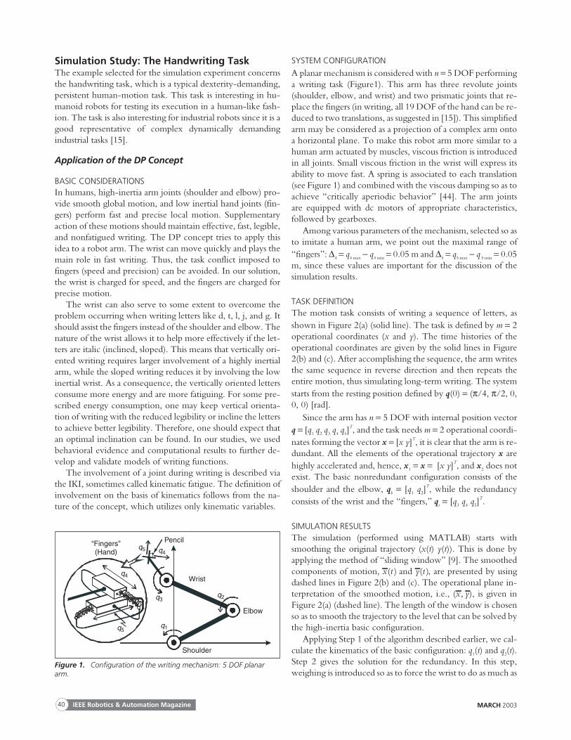
SYSTEM CONFIGURATION
A planar mechanism is considered with n = 5 DOF performinga writing task (Figure1). This arm has three revolute joints(shoulder, elbow, and wrist) and two prismatic joints that re-place the fingers (in writing, all 19 DOF of the hand can be re-duced to two translations, as suggested in [15]). This simplifiedarm may be considered as a projection of a complex arm ontoa horizontal plane. To make this robot arm more similar to ahuman arm actuated by muscles, viscous friction is introducedin all joints. Small viscous friction in the wrist will express itsability to move fast. A spring is associated to each translation(see Figure 1) and combined with the viscous damping so as toachieve “critically aperiodic behavior” [44]. The arm jointsare equipped with dc motors of appropriate characteristics,followed by gearboxes.
Among various parameters of the mechanism, selected so asto imitate a human arm, we point out the maximal range of“fingers”: ∆4 = q4 max − q4 min = 0.05 m and ∆5 = q5 max − q 5 min = 0.05m, since these values are important for the discussion of thesimulation results.
TASK DEFINITIONThe motion task consists of writing a sequence of letters, asshown in Figure 2(a) (solid line). The task is defined by m = 2operational coordinates (x and y). The time histories of theoperational coordinates are given by the solid lines in Figure2(b) and (c). After accomplishing the sequence, the arm writesthe same sequence in reverse direction and then repeats theentire motion, thus simulating long-term writing. The systemstarts from the resting position defined by q(0) = (π/4, π/2, 0,0, 0) [rad].
Since the arm has n = 5 DOF with internal position vectorq = [q1 q2 q3 q4 q5]
T, and the task needs m = 2 operational coordi-nates forming the vector x = [x y]T, it is clear that the arm is re-dundant. All the elements of the operational trajectory x arehighly accelerated and, hence, x1 = x = [x y]T, and x2 does notexist. The basic nonredundant configuration consists of theshoulder and the elbow, qb = [q1 q2]
T, while the redundancyconsists of the wrist and the “fingers,” qr = [q3 q4 q5]
T.
SIMULATION RESULTSThe simulation (performed using MATLAB) starts withsmoothing the original trajectory (x(t) y(t)). This is done byapplying the method of “sliding window” [9]. The smoothedcomponents of motion, x t( ) and y t( ), are presented by usingdashed lines in Figure 2(b) and (c). The operational plane in-terpretation of the smoothed motion, i.e., (x y, ), is given inFigure 2(a) (dashed line). The length of the window is chosenso as to smooth the trajectory to the level that can be solved bythe high-inertia basic configuration.
Applying Step 1 of the algorithm described earlier, we cal-culate the kinematics of the basic configuration: q1(t) and q2(t).Step 2 gives the solution for the redundancy. In this step,weighing is introduced so as to force the wrist to do as much as
MARCH 2003IEEE Robotics & Automation Magazine40
“Fingers”(Hand)
q5 q4
q4
q3
q1q5
q2
Elbow
Shoulder
Wrist
Pencil
Figure 1. Configuration of the writing mechanism: 5 DOF planararm.
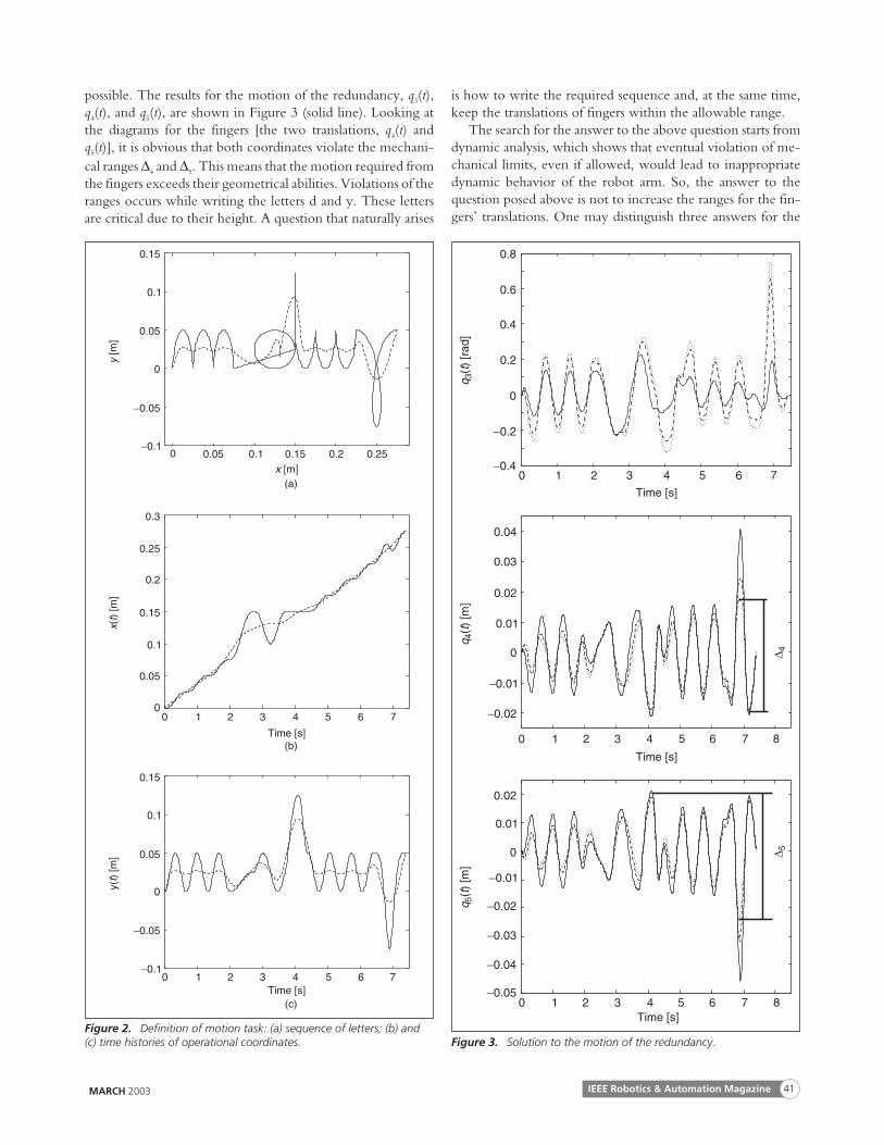
possible. The results for the motion of the redundancy, q3(t),q4(t), and q5(t), are shown in Figure 3 (solid line). Looking atthe diagrams for the fingers [the two translations, q4(t) andq5(t)], it is obvious that both coordinates violate the mechani-cal ranges ∆4 and ∆5. This means that the motion required fromthe fingers exceeds their geometrical abilities. Violations of theranges occurs while writing the letters d and y. These lettersare critical due to their height. A question that naturally arises
is how to write the required sequence and, at the same time,keep the translations of fingers within the allowable range.
The search for the answer to the above question starts fromdynamic analysis, which shows that eventual violation of me-chanical limits, even if allowed, would lead to inappropriatedynamic behavior of the robot arm. So, the answer to thequestion posed above is not to increase the ranges for the fin-gers’ translations. One may distinguish three answers for the
MARCH 2003 IEEE Robotics & Automation Magazine 41
0.15
0.1
0.05
0
−0.05
−0.10 0.05 0.1 0.15 0.2 0.25
x [m]
y[m
]
0.3
0.25
0.2
0.15
0.1
0.05
0
0.15
0.1
0.05
0
−0.05
−0.1
xt()
[m]
y()
[m]
t
0 1 2 3 4 5 6 7
0 1 2 3 4 5 6 7
Time [s]
Time [s]
(a)
(b)
(c)
Figure 2. Definition of motion task: (a) sequence of letters; (b) and(c) time histories of operational coordinates.
0.8
0.6
0.4
0.2
0
−0.40 1 2 3 4 5
Time [s]
qt
3()
[rad
]
0.04
0.03
0.02
0.01
0
−0.01
0.02
0.01
0
−0.01
qt
4()
[m]
qt
5()
[m]
0 1 2 3 4 5 6 7
0 1 2 3 4 5 6 7
Time [s]
Time [s]
−0.2
6 7
−0.02
8
−0.02
8
−0.03
−0.04
−0.05
∆ 5∆ 4
Figure 3. Solution to the motion of the redundancy.
question under examination. The first suggests to reduce thefingers’ involvement by requiring the shoulder and the elbowto help. This can be done by reducing the level of smoothing.Such a solution may be good for a human arm that has enoughreserve in muscle power. In robots, the reserve is likely to besmaller. However, even for humans, the increased engage-ment of the heavy arm is not desirable since it leads to fatigue.Therefore, such an answer cannot be considered as appropri-ate. The second answer is to simply reduce the fingers’ mo-tions (without any additional help) until they fall into theallowable regions. This solution implies a deformation in theshape of letters, which reduces the legibility. With humans,this solution can be applied and is acceptable.
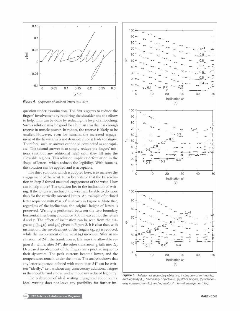
The third solution, which is adopted here, is to increase theengagement of the wrist. It has been stated that the IK resolu-tion in Step 2 forced maximal engagement of the wrist. Howcan it help more? The solution lies in the inclination of writ-ing. If the letters are inclined, the wrist will be able to do morethan for the vertically oriented letters. An example of inclinedletter sequence with α = 30° is shown in Figure 4. Note that,regardless of the inclination, the original height of letters ispreserved. Writing is performed between the two boundaryhorizontal lines being at distance 0.05 m, except for the lettersd and y. The effects of inclination can be seen from the dia-grams q3(t), q4(t), and q5(t) given in Figure 3. It is clear that, withinclination, the involvement of the fingers (q4, q5) is reduced,while the involvement of the wrist (q3) increases. After an in-clination of 24°, the translation q4 falls into the allowable re-gion ∆4, while, after 34°, the other translation q5 falls into ∆5.Decreased involvement of the fingers has a positive impact totheir dynamics. The peak currents become lower, and thetemperatures remain under the limits. The analysis shows thatany letter sequence inclined with more than 34° can be writ-ten “ideally,” i.e., without any unnecessary additional fatiguein the shoulder and elbow, and without any reduced legibility.
The realization of ideal writing engages all robot joints.Ideal writing does not leave any possibility for further im-
MARCH 2003IEEE Robotics & Automation Magazine42
y[m
]0.15
0.1
0.05
0
−0.05
−0.10 0.05 0.1 0.15 0.2 0.25 0.3
x [m]
Figure 4. Sequence of inclined letters (α = 30°).
IKI
0
10
20
30
40
50
60
70
80
90
100
0 10 20 30 40 50
Inclination α°
Le=1
0.9
0.8
0.7
0.6
0.5
0.40.30.20.1
(a)
En
0
10
20
30
40
50
60
70
80
90
100
0 10 20 30 40 50
Inclination α°
Le=1
0.9
0.80.7
0.60.5
0.4
0.30.20.1
(b)
Θn
30
40
50
60
70
80
90
100
0 10 20 30 40 50
Inclination α°
Le=1
0.90.8
0.70.6
0.50.4
0.30.20.1
(c)
Figure 5. Relation of secondary objective, inclination of writing (α),and legibility (Le). Secondary objective is: (a) IKI of fingers, (b) total en-ergy consumption (En), and (c) motors’ thermal engagement (Θn).
provement of motion by optimizing some second-ary objective (e.g., any one of the cost functionsmentioned above). Only the primary objective, leg-ibility, is maximized. However, it is a well-knownfact that humans often do not insist on ideal legibil-ity. They are satisfied with some lower, but stillreadable level. This means that a redistribution ofthe involvement of joints could be made, offeringthe possibility to optimize some secondary objec-tive and, perhaps, obtain a more appropriate mo-tion. To this end, it is necessary to numericallyexpress the primary objective (legibility). Here, wedefine the legibility of a sequence of letters on thebasis of a mean square deviation from the ideal se-quence. If e is the mean square error, then legibilityis its normalized value: Le = (emax − e)/(emax − emin). Theerror value emin = 0 corresponds to ideal writing,while emax corresponds to the threshold—the lowestlegibility still worth considering. For this study, emax
= 0.0163. So, legibility is within the boundaries 0 ≤Le ≤ 1, where 1 stands for ideal writing, and 0 for thethreshold. Note that for any inclination there existsan ideally legible sequence.
The IKI of the fingers is our first choice for thesecondary objective. This is motivated by the hu-man intention to reduce the engagement of musclesthat can be easily fatigued. Figure 5(a) shows the re-lation of IKI, inclination, and legibility. Each curvecorresponds to some level of legibility (Le) andshows how IKI depends on the inclination angle(α). Each curve features a clear minimum. Reduc-ing the legibility, the point of minimum movesslightly to the left (towards smaller inclinations).Observing the diagrams, one can conclude that, forany selected level of legibility, there exists an opti-mal inclination that minimizes the involvement(IKI) of fingers (for instance, if legibility is pre-scribed to be 0.6, then the optimal inclination is40°, and the corresponding IKI is about 28).
The second choice for the secondary objective isbased on the “total energy consumption” E. Nor-malization is made producing the value En from theinterval [0, 100]. Figure 5(b) shows the relation ofEn, inclination, and legibility. Finally, the thirdchoice of the secondary objective is the thermal en-gagement of motors. The normalized sum ofsteady-state temperatures, Θn ∈[0, 100], is consid-ered [Figure 5(c)]. The diagrams of Figure 5 showsimilar characteristics for all three secondary objec-tives. For any selected level of legibility, there existsan optimal inclination that minimizes the cost func-tion (for En and Θn, the points of minimum becomesless expressed when reducing legibility). For in-stance, if legibility is 0.6, then En reduces to 30 for
MARCH 2003 IEEE Robotics & Automation Magazine 43
(,
,)
-S
cale
zz
11
,1Θ
af
40
35
30
25
DK
I 1-
Sca
le
1.00
0.98
0.96
0.94
0.92
0.90
0 100 200 300 400 500 600 700 800Time [s]
DKI1
Θ °a,1 [ C]
z z1 1, f
(b)
(,
,)
-S
cale
zz
22
,2Θ
af
25
DK
I 2-
Sca
le
1.00
0.95
0.90
0.85
0.80
0.75
0 100 200 300 400 500 600 700 800Time [s]
DKI2
Θ °a,2 [ C]
z z2 2, f
(c)
(,
,)
-S
cale
zz
33
,3Θ
af
361.00
0.95
0.90
0.85
0.80
0.75
0 100 200 300 400 500 600 700 800Time [s]
DKI3
Θ °a,3 [ C]
z z3 3, f
(d)
(,
,)
-S
cale
zz
44
,4Θ
af
1.00
0.95
0.90
0.85
0.80
0.75
0 100 200 300 400 500 600 700 800Time [s]
DKI4
Θ °a,4 [ C]
z z4 4, f
(e)
(,
,)
-S
cale
zz
55
,5Θ
af
1.0
0 100 200 300 400 500 600 700 800Time [s]
DKI5
Θ °a,5 [ C]
z z5 5, f
DK
I 3-
Sca
leD
KI 4
-S
cale
DK
I 5-
Sca
le
(a)
30
35
40
45
50
55
60
65
34
32
30
28
26
0.70
55
50
45
40
35
30
25
0.70
0.65
60
25
55
50
45
40
35
30
0.9
0.8
0.7
0.6
0.5
Figure 6. Time histories of the DKI, the virtual fatigues, and the motor tempera-tures in the arm joints 1,2,…,5.
the optimal inclination of 33°, while Θn reduces to 47 for itsoptimal inclination of 40°).
The DP concept can be used both for online control andfor offline motion planning. The majority of the results pre-sented in this section were based on integral criteria that aresuitable for the off-line approach.
Application of the Virtual Fatigue Concept
BASIC CONSIDERATIONSIf the fatigue in some muscles of the human arm exceeds thethreshold level, the arm tends to reconfigure itself and disturbsthe steady state imposed by the DP concept. Online reconfig-uration is needed since it must be based on the current level offatigue. To solve this problem for the robot arm, we follow anapproach that is based on the VF concept. The approach triesto satisfy two criteria: the DP and the comfortable motion.The distribution of motions obtained from these two optimi-zation criteria holds until the level of VF in some joint reachesthe prescribed critical level. After that, a penalty function startsto act, forcing depressed involvement of the exhausted joint.Then, redistribution of motion occurs. Higher engagement ofother joints enables the exhausted one (or ones) to have a rest.
TASK DEFINITION
The task is to write a sequence of letters inclined for 30°, asshown in Figure 4. After accomplishing the sequences, thearm writes the same sequence in reverse and then repeats theentire motion, thus simulating long-term writing.
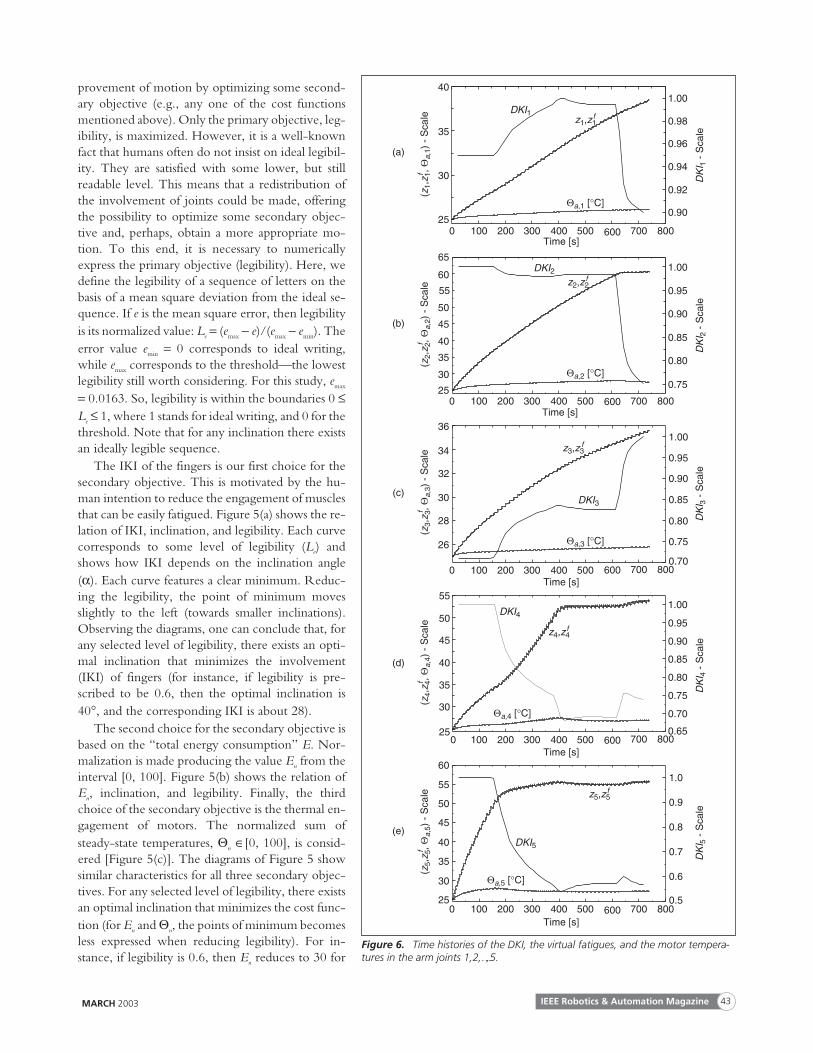
SIMULATION RESULTSAmong the various parameters used for the VF models andtheir application, we point out the critical levels of VF: zcr,1 =zcr,2, = zcr,3 = 60, zcr,4, = zcr,5 = 50, since these values are impor-tant for the understanding of the simulation results.
The simulation test was made by using the second-ordermodel of VF. Figure 6 shows how the “involvement of joints”changes with the time. In order to express the current level ofinvolvement, DKI is used. The time histories of DKIj, j = 1...,5are shown, which are normalized in the interval [0, 1]. Figure6 also shows the time histories of the virtual fatigues of the armjoints (VFj, i.e., zj) and the corresponding rotor temperatures(Θa,j). Because of the nonuniform motion in the writing task,oscillations in VF responses occur that may seriously disturbthe operation of penalty functions. For this reason, a low-passfilter is applied. The filtered version zf
j is now used in the con-trol algorithm as input to the penalty functions. Figure 6 pres-ents both zj and zf
j, but the filtered curve is covered by itsoscillatory original.
By inspecting the diagrams of VF, it can be seen that Joint 5is the first to reach the critical level of fatigue (zf
5 ≥ z5,cr = 50).After finger q5 “feels” fatigue (this happens in about 160 s), thepenalty function ϕ5(z
f
5) activates a depression of involvementof the exhausted translation that corresponds to the drop ofDKI5. Redistribution of motion leads to considerably higher
involvement of the wrist q3, which is expressed by the in-creased DKI3. Fatigue (z4 and zf
4) continues to rise untilreaches the limit z4, cr (t about 375 s). The activated penaltyfunction ϕ4(z
f
4) reduces the engagement of q4 (new drop inDKI4). After that, the fingers keep almost the constant level offatigue. Fatigue, however, appears in the elbow (z2 reachedthe limit of 60 in about 625 s). The penalty function ϕ2 de-creases the elbow’s involvement (drop in DKI2), thus prevent-ing some greater violation of the fatigue limit. This is followedby a new considerable progress of the wrist engagement DKI3.A small rise in fingers’ involvement is also present after the el-bow feels fatigue, but the main help comes from the wrist.
ConclusionTwo approaches were proposed to model and control a hu-man-like motion of robot arms. The first, which is based onthe concept of distributed positioning (DP), was suggested as agood model of arm motion in the phase where fatigue doesnot appear. The prescribed motion of the end-effector wasdistributed to a redundant number of arm joints in accordanceto their acceleration capabilities. For the phase where fatigueappears, the concept of virtual fatigue was proposed. This arti-ficial variable, which is based on robot dynamics, emulates theprogress of biological fatigue.
The human handwriting task was chosen for the simula-tion. The DP concept was tested first by modeling thenonfatigued motion. The justification of the usual inclinationof letters was presented, and the relation between the inclina-tion, legibility, and a secondary objective (fingers’ involve-ment, energy consumption, motors’ thermal load) wasdiscussed. It was found that, for some prescribed level of legi-bility, the individual optima of all the secondary cost functionswere quite near to each other.
Writing in the presence of fatigue was also analyzed, apply-ing the method of the so-called “virtual fatigue.” Penaltyfunctions were utilized to ensure redistribution of joint in-volvement when some of them “felt” fatigue. The arm auto-matically adapted to the situation, taking a new posture givingthe exhausted joint the chance to rest while engaging theother joints more.
KeywordsMan-machine analogy, human-like motion, redundancy res-olution, robot fatigue, humanoid, handwriting.
References[1] S.G. Tzafestas, Intelligent Robotic Systems. New York: Marcel Dekker,
1991.
[2] S.G. Tzafestas, Robotic Systems: Advanced Techniques and Applications. Nor-well, MA: Kluwer, 1992.
[3] A. Liégeois, “Automatic supervisory control of the configuration and be-havior of multibody mechanisms,” IEEE Trans. Syst., Man, Cybern., vol.7, pp. 868-871, Dec. 1977.
[4] A.A. Maciejewski and C.A. Klein, “Obstacle avoidance for kinematicallyredundant manipulators in dynamically varying environments,” Int. J.Robot. Res., vol. 4, no. 33, pp. 109-117, 1985.
MARCH 2003IEEE Robotics & Automation Magazine44
[5] T. Yoshikawa, “Manipulability of robotic mechanisms,” Int. J. Robot.Res., vol. 4, no. 2, pp. 3-9, 1985.
[6] K.N. Groom, A.A. Maciejewski, and V. Balakrishnan, “Real-time fail-ure-tolerant control of kinematically redundant manipulators,” in Proc.IEEE Int. Conf. Robotics and Automation, Albuquerque, NM, Apr. 1997,pp. 2595-2600.
[7] M. Vukobratovic and M. Kircanski, Kinematics and Trajectory Synthesis ofManipulation Robots. Berlin, Germany: Springer-Verlag, 1986.
[8] J.M. Hollerbach and K.C. Suh, “Redundancy resolution of manipulatorsthrough torque optimization,” IEEE J. Robot. Automat., vol. RA-3, pp.308-316, Aug. 1987.
[9] V. Potkonjak, “Distributed positioning for redundant robotic systems,”Robotica, vol. 8, no. 1, pp. 61-76, 1990.
[10] V. Potkonjak, “New approach to the application of redundant robots,”Int. J. Robot. Comput.—Integrated Manuf., vol. 8, no. 3, pp. 181-185,1991.
[11] V. Potkonjak and A. Krstulovic, “Contribution to the kinematics and dy-namics of redundant robots via distributed positioning,” J. Intell. Robot.Syst., vol. 5, pp. 229-239, 1992.
[12] V. Potkonjak, G.S. Djordjevic, C. Milosavljevic, D. Antic, and D.Popovic, “Variable structure systems for control of redundant robots,” J.Robot. Autonomous Syst., vol. 13, pp. 13-24, 1994.
[13] V. Potkonjak and A. Krstulovic, “Mathematical modelling of a redun-dant anthropomorphic arm (Part I),” Robot. Autonomous Syst., vol. 9, pp.165-170, 1992.
[14] V. Potkonjak and A. Krstulovic, “Simulation of a redundant anthropo-morphic arm (Part II),” Robot. Autonomous Syst., vol. 9, pp. 171-179,1992.
[15] V. Potkonjak, M. Popovic, M. Lazarevic, and J. Sinanovic, “Redun-dancy problem in writing: From human to anthropomorphic robotarm,” IEEE Trans. Syst., Man, Cybern. B, vol. 28, pp. 790-805, 1998.
[16] Y. Nakamura, Advanced Robotics: Redundancy and Optimization. Reading,MA: Addison-Wesley, 1991.
[17] D.P. Martin, J. Baillieul, and J.M. Hollerbach, “Resolution of kinematicredundancy using optimization techniques,” IEEE Trans. Robot. Auto-mat., vol. 5, pp. 529-533, Aug. 1989.
[18] S.G. Tzafestas, A. Zagorianos, and P. Dimou, “Velocity control of re-dundant robots using a global optimization approach,” Syst. Anal. Model.Simul., vol. 29, pp. 287-299, 1997.
[19] J. Baillieul, “Kinematic programming alternatives for redundant manipu-lators,” in Proc. IEEE Conf. Robotics and Automation, St. Louis, MO,1985, pp. 722-728.
[20] H. Seraji, “Configuration control of redundant manipulators: Theoryand implementation,” IEEE Trans. Robot. Automat., vol. 5, pp. 472-490,Aug. 1989.
[21] L. Sciavicco and B. Siciliano, Modeling and Control of Robot Manipulators.New York: McGraw-Hill, 1996.
[22] D.R. Baker and C.W. Wampler, II, “On the inverse kinematics of re-dundant manipulators,” Int. J. Robot. Res., vol. 7, no. 2, pp. 3-21,Mar./Apr. 1988.
[23] G.S. Djordjevic, M. Rasic, D. Kostic, and V. Potkonjak, “Representa-tion of robot motion control skill,” IEEE Trans. Syst., Man, Cybern. C,vol. 30, pp. 219-238, May 2000.
[24] A. Zagorianos, E. Kontoyiannis, and G.S. Tzafestas, “Resolved motionmodel-based predictive control of redundant robots,” Math. Comput.Simul., vol. 37, pp. 195-205, 1994.
[25] M.L. Lathash, Control of Human Movement. Champaign, IL: Human Ki-netics Publishers, 1993.
[26] D. Michel, “Learning from human’s strategies of motor control: A chal-lenge for robotic systems design,” in Proc. IEEE Int. Workshop Robot andHuman Communication, Tsukuba, Japan, 1996, pp. 223-228.
[27] H. Cruse, E. Wischmeyer, M. Bruwer, P. Brockfield, and A. Dress, “Onthe cost functions for the control of the human arm movement,” Biol.Cybern., vol. 62, no. 6, pp. 519-528, 1990.
[28] O. Khatib, “Dynamic control of manipulators in operational space,” inProc. 6th IFToMM Congr. Theory Machines and Mechanisms, New Delhi,India, 1983, pp. 1123-1131.
[29] N. Hogan, “An organizing principle for a class of voluntary movements,”J. Neurosci., vol. 4, no. 11, pp. 2745-2754, 1984.
[30] A.H. Sief-Naraghi and J.M. Winters, “Changes in musculosceletal con-trol strategies with loading: Inertial, isotonic, random,” in Proc. ASMEBiomech. Symp., 1989, vol. AMD-98, pp. 355-358.
[31] O. Fuentes and R.C. Nelson, “Morphing hands and virtual tools (orWhat good is an extra degree of freedom?),” Computer Science Dept.,Univ. of Rochester, Rochester, New York, Tech. Rep. 551, Dec. 1994.
[32] E.S. Jung, J. Choe, and S.H. Kim, “Psychophysical cost function of jointmovement for arm reach posture prediction,” in Proc. Human Factors andErgonomics Society 38th Annu. Meeting, Nashville, TN, 1994, vol. 1, pp.636-640.
[33] T.F. Chan and R.V. Dubey, “A weighted least-norm solution basedscheme for avoiding joint limits for redundant joint manipulators,” IEEETrans. Robot. Automat., vol. 11, pp. 286-292, Apr. 1995.
[34] J. Mizrahi, “Fatigue in muscles activated by functional electrical stimula-tion,” Crit. Rev. Phys. Rehabilitation Med., vol. 9, no. 2, pp. 93-129,1997.
[35] T. Öberg, “Subjective and objective evaluation of shoulder muscle fa-tigue,” Ergonomics, vol. 37, no. 8, pp. 1323-1333, 1994.
[36] T. Kiryu, M. Morishiata, H. Yamada, and M. Okada, “A muscular fa-tigue index based on the relationships between superimposed M waveand preceding background activity,” Trans. IEEE Biomed. Eng., vol. 45,pp. 1194-1204, Oct. 1998.
[37] H.P. Peckham, “Electrical excitation of skeletal muscle: Alterations inforce, fatigue and metabolic properties,” Case Western Reserve Univ.,Cleveland, OH, Rep. EDC 4-72-32, Aug. 1972.
[38] L. Vodovnik and S. Rebersek, “Improvements in voluntary control ofparetic muscles due to electrical stimulation,” in Electrical Stimulation as aRehabilitation Method to Improve Abnormal Locomotion and Manipulation,W.S. Fields, Ed. New York: Int. Medical Book Corp., 1973, pp.101-116.
[39] Y. Giat, J. Mizrahi, and M. Levy, “A model of fatigue and recovery inparaplegic’s quadriceps muscle subjected to intermittent FES,” J.Biomech. Eng., vol. 118, no. 3, pp. 357-366, Aug. 1996.
[40] D.G. Jenkins and B.M. Quigley, “Endurance training enhances criticalpower,” Med. Sci. Sports and Exerc. Med., vol. 24, no. 11, pp. 1283-1289,Nov. 1992.
[41] B.S. Gottfried and J. Weisman, Introduction to Optimization Theory.Englewood Cliffs, NJ: Prentice-Hall, 1973.
[42] D.E. Whitney, “The mathematics of coordinated control of prostheticarms and manipulators,” Trans. ASME, J. Dyn. Syst., Meas. Control, vol.94, no. 4, pp. 303-309, Dec. 1972.
[43] V. Potkonjak, “Thermal analysis and dynamic capabilities of dc motors inindustrial robotic systems,” Robot. Comput.-Integr. Manuf., vol. 5, no.2/3, pp. 137-143, 1989.
[44] T. Shepel, “A robotic model of movement for the left index finger,”Dept. Electrical Eng., Univ. of Alberta, Edmonton, Alberta, Canada, ful-fillment of EE 565 Robotics Project, 1995.
MARCH 2003 IEEE Robotics & Automation Magazine 45
Veljko Potkonjak studied at the Faculty of Electrical Engineer-ing, University of Belgrade, and graduated in 1974. The sameyear, he was accepted in postgraduate studies at the same facultyand finished in 1977. In 1981 he defended his doctoral thesis.
After graduation, Potkonjak started his work at the Facultyof Electrical Engineering, Belgrade, as an assistant in the fieldof mechanics. He became an assistant professor in 1985, and,in 1990, was promoted to the rank of associate professor, and,finally, in 1995, to the rank of full professor. During his educa-tional career, he has been teaching mechanics, robotics, andbiomechanics. He was also a teacher or a visiting researcher atthe Faculty of Electronics, University of Nish, the TechnicalFaculty in Cacak, National Technical Univeresity of Athens,and American University of Athens.
The research interests of Prof. Potkonjak primarly concernrobotics. His attention has been oriented to problems con-cerning the modeling of robotic systems and the implementa-tion of these models to design and control. He is the aauthor/co-author of two international research monographs(in English), two chapters in the Handbook of Mechanical Sys-tems Design, several textbooks for university and for secondaryschools, about 50 international journal papers, 25 papers oninternational conferences, and many papers in Yugoslav jour-nals and domestic conferences. Prof. Potkonjak has written alarge number of reviews for respected international journalsand conferences as well as for domestic conferences.
Spyros Tzafestas is a full professor and director of the Insti-tute of Communication and Computer Systems (ICCS), theSignals, Control, and Robotics Division, and the IntelligentRobotics and Automation Laboratory (IRAL) of the NationalTechnical University of Athens (NTUA). He is the holder ofPh.D. and D.Sc. degrees in control and automation and hon-orary doctorates of the International University [D.Sc.(Hon.)] and the Technical University of Munich (Dr.-Ing.E.h.). He was a project evaluator of national European and in-ternational projects (United States, Canada, Italy, Hong Kong,Japan) and project coordinator of national and EU projects inthe fields of robotics, CIM, and IT. His publications include30 research books, 60 book chapters, and over 700 journal andconference technical papers. He is editor-in-chief of the Jour-nal of Intelligent and Robotic Systems and the book series Micro-processor-Based and Intelligent Systems Engineering (K1uwer). He
organized several international conferences. His current inter-ests include control, robotics, and CIM.
Dragan Kostic received the B.Sc. and M.Sc. degrees in auto-matic control and robotics from the Faculty of Electronic En-gineering, University of Niš, Serbia, in 1994 and 2000,respectively. Since 2000, he has been a Ph.D. student with theDynamics and Control Technology Group at the Departmentof Mechanical Engineering, Eindhoven University of Tech-nology, The Netherlands. Previously, he was investigatedproblems in biomechanics and ergonomics. His current re-search interests include dynamic modeling, identification, androbust and data-based control of nonlinear mechanical sys-tems, in particular robots.
Goran Djordjevic received the B.Sc., M.Sc., and Ph.D. de-grees, all in electrical engineering, from the University of Niš,Niš, Yugoslavia, in 1988, 1992, and 1995, respectively. From1988-1995, he was research and teaching assistant at the De-partment of Automatic Control, Faculty of Electronic Engi-neering, University of Niš. Since 1996, he has been an assistantprofessor of automatic control, robotics, robot control, andflexible automation at the University of Niš. He is head of theRobotics and Automation Lab and works with The JohnsHopkins University, Department of Biomedical Engineering,Baltimore, Maryland, USA, developing intelligent controllersof biomimetic robots. His research interests include intelli-gent, biologically inspired solutions to robot control, roboticsin medicine, data modeling, and PC-based control.
Milan Rasic received the B.Sc. and M.Sc. degrees in electri-cal engineering from the Faculty of Electronic Engineering,University of Niš, in 1996 and 2000, respectively. He is ateaching assistant at the Department of Automatic Controland a researcher of the Robotics and Automation Lab at theFaculty of the Electronic Engineering in Niš. His research in-terests include robotics, intelligent control, embedded controlsystems, and application of PCs in control and data acquisition.
Address for Correspondence: Veljko Potkonjak, Faculty ofElectrical Engineering, University of Belgrade, BulevarRevolucije 73, 11000 Belgrade, Yugoslavia. E-mail: [email protected].
MARCH 2003IEEE Robotics & Automation Magazine46
Related Documents