Introduction The reflectarray antenna was first intro- duced by Barry and Malech in their paper [1] from 1963. A reflectarray antenna consists of an illuminating antenna (feed) and a flat or curved reflector built of reflectarray elements (see Fig. 1). Reflectarray elements retransmit signals from the feed and introduce such phase delay that a plane wave is formed in a given direc- tion. Reflectarrays may be an interesting alternative to classic array antennas [2], because they do not contain a beamforming network in its classic form. Instead, the free space between the feed and reflector aperture acts as a beamforming network. Lack of a traditional beamformer leads to increased reliability of the entire antenna, because the reflectarray ele- ments are isolated from each other and decrease the total weight of antenna. In addition, when the reflector contains sev- eral thousand elements [3] there is no need to build an extensive signal divider, which would be very complicated in case of clas- sic array antennas. However, it needs to be stressed that in reflectarray antennas, using free space as the beamforming net- work leads to a fundamental design problem: how to choose the proper mutual position between the feed and the reflector. Another problem, connected with the for- mer, is the choice of a correct radiation pattern of the feed. All these parameters affect the reflectarray efficiency, which should obviously be possibly high. In this paper formulas are derived which describe the relationship between parameters of a rectangular reflec- tarray and its antenna efficiency (character- ized by two components: illumination effi- ciency and spillover efficiency). By plotting antenna efficiency versus certain antenna parameters, the designer can choose parame- ter values which maximize the reflectarray efficiency. Definitions of Illumination and Spillover Efficiencies The definitions of illumination and spill- over efficiencies [3][4][5] utilize three power 28 High Frequency Electronics Reflectarray Antennas Illumination and Spillover Efficiency Calculations for Rectangular Reflectarray Antennas By Michał ŻŻebrowski Reflectarray antennas can be an interesting alternative to classic array antennas. High Frequency Design Figure 1 • Reflectarray schematic with reflectarray elements and feed marked in yellow.

Welcome message from author
This document is posted to help you gain knowledge. Please leave a comment to let me know what you think about it! Share it to your friends and learn new things together.
Transcript
IntroductionThe reflectarray
antenna was first intro-duced by Barry and Malech in their paper [1] from 1963. A reflectarray
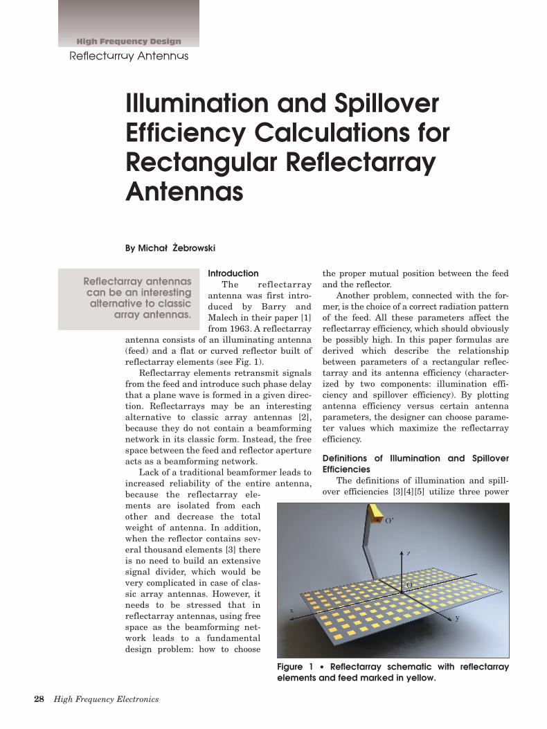
antenna consists of an illuminating antenna (feed) and a flat or curved reflector built of reflectarray elements (see Fig. 1).
Reflectarray elements retransmit signals from the feed and introduce such phase delay that a plane wave is formed in a given direc-tion. Reflectarrays may be an interesting alternative to classic array antennas [2], because they do not contain a beamforming network in its classic form. Instead, the free space between the feed and reflector aperture acts as a beamforming network.
Lack of a traditional beamformer leads to increased reliability of the entire antenna, because the reflectarray ele-ments are isolated from each other and decrease the total weight of antenna. In addition, when the reflector contains sev-eral thousand elements [3] there is no need to build an extensive signal divider, which would be very complicated in case of clas-sic array antennas. However, it needs to be stressed that in reflectarray antennas, using free space as the beamforming net-work leads to a fundamental design problem: how to choose
the proper mutual position between the feed and the reflector.
Another problem, connected with the for-mer, is the choice of a correct radiation pattern of the feed. All these parameters affect the reflectarray efficiency, which should obviously be possibly high. In this paper formulas are derived which describe the relationship between parameters of a rectangular reflec-tarray and its antenna efficiency (character-ized by two components: illumination effi-ciency and spillover efficiency). By plotting antenna efficiency versus certain antenna parameters, the designer can choose parame-ter values which maximize the reflectarray efficiency.
Definitions of Illumination and Spillover Efficiencies
The definitions of illumination and spill-over efficiencies [3][4][5] utilize three power
28 High Frequency Electronics
Reflectarray Antennas
Illumination and Spillover Efficiency Calculations for Rectangular Reflectarray Antennas
By Michał ŻŻebrowski
Reflectarray antennas can be an interesting alternative to classic
array antennas.
High Frequency Design
Figure 1 • Reflectarray schematic with reflectarray elements and feed marked in yellow.
30 High Frequency Electronics
High Frequency Design
Reflectarray Antennas
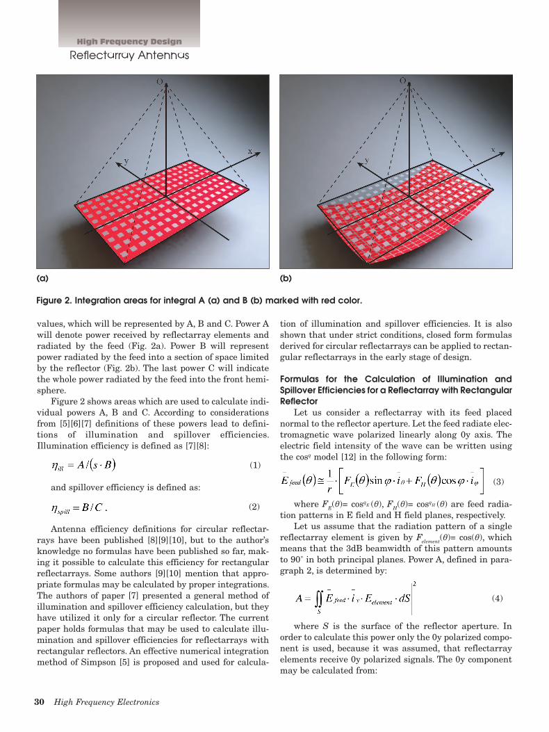
values, which will be represented by A, B and C. Power A will denote power received by reflectarray elements and radiated by the feed (Fig. 2a). Power B will represent power radiated by the feed into a section of space limited by the reflector (Fig. 2b). The last power C will indicate the whole power radiated by the feed into the front hemi-sphere.
Figure 2 shows areas which are used to calculate indi-vidual powers A, B and C. According to considerations from [5][6][7] definitions of these powers lead to defini-tions of illumination and spillover efficiencies. Illumination efficiency is defined as [7][8]:
(1)
and spillover efficiency is defined as:
(2)
Antenna efficiency definitions for circular reflectar-rays have been published [8][9][10], but to the author’s knowledge no formulas have been published so far, mak-ing it possible to calculate this efficiency for rectangular reflectarrays. Some authors [9][10] mention that appro-priate formulas may be calculated by proper integrations. The authors of paper [7] presented a general method of illumination and spillover efficiency calculation, but they have utilized it only for a circular reflector. The current paper holds formulas that may be used to calculate illu-mination and spillover efficiencies for reflectarrays with rectangular reflectors. An effective numerical integration method of Simpson [5] is proposed and used for calcula-
tion of illumination and spillover efficiencies. It is also shown that under strict conditions, closed form formulas derived for circular reflectarrays can be applied to rectan-gular reflectarrays in the early stage of design.
Formulas for the Calculation of Illumination and Spillover Efficiencies for a Reflectarray with Rectangular Reflector
Let us consider a reflectarray with its feed placed normal to the reflector aperture. Let the feed radiate elec-tromagnetic wave polarized linearly along 0y axis. The electric field intensity of the wave can be written using the cosq model [12] in the following form:
(3)
where FE(θ)= cosqE (θ), FH(θ)= cosq
H (θ) are feed radia-tion patterns in E field and H field planes, respectively.
Let us assume that the radiation pattern of a single reflectarray element is given by Felement(θ)= cos(θ), which means that the 3dB beamwidth of this pattern amounts to 90˚ in both principal planes. Power A, defined in para-graph 2, is determined by:
(4)
where S is the surface of the reflector aperture. In order to calculate this power only the 0y polarized compo-nent is used, because it was assumed, that reflectarray elements receive 0y polarized signals. The 0y component may be calculated from:
Figure 2. Integration areas for integral A (a) and B (b) marked with red color.
(b)(a)
32 High Frequency Electronics
High Frequency Design
Reflectarray Antennas
(5)
For electric field intensity in (4) the 0y component takes the following form:
(6)
Based on the assumptions so far, one can calculate power B (see definition in paragraph 2) using the following for-mula:
(7)
where S’ is the surface of the sphere, limited by the reflector aperture (see Fig. 2b). The last of the powers from paragraph 2, power C, can be calculated from:
(8)
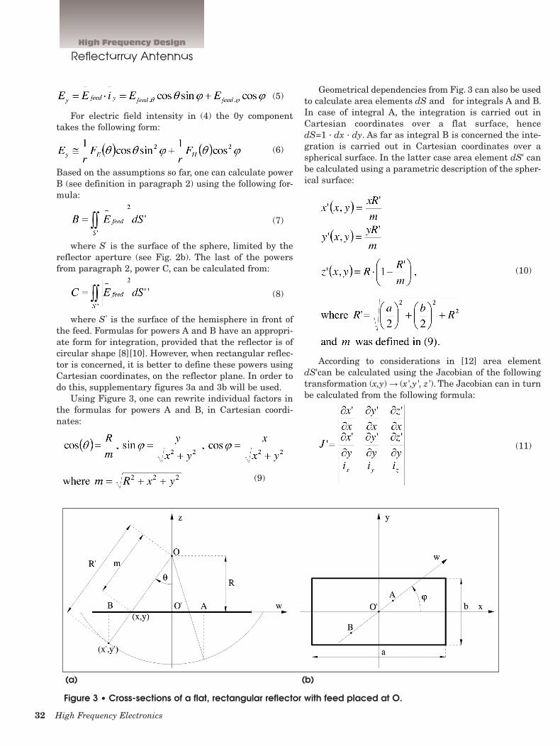
where S'' is the surface of the hemisphere in front of the feed. Formulas for powers A and B have an appropri-ate form for integration, provided that the reflector is of circular shape [8][10]. However, when rectangular reflec-tor is concerned, it is better to define these powers using Cartesian coordinates, on the reflector plane. In order to do this, supplementary figures 3a and 3b will be used.
Using Figure 3, one can rewrite individual factors in the formulas for powers A and B, in Cartesian coordi-nates:
Geometrical dependencies from Fig. 3 can also be used to calculate area elements dS and for integrals A and B. In case of integral A, the integration is carried out in Cartesian coordinates over a flat surface, hence dS=1 ∙ dx ∙ dy. As far as integral B is concerned the inte-gration is carried out in Cartesian coordinates over a spherical surface. In the latter case area element dS' can be calculated using a parametric description of the spher-ical surface:
(10)
According to considerations in [12] area element dS'can be calculated using the Jacobian of the following transformation (x,y) → (x',y', z'). The Jacobian can in turn be calculated from the following formula:
(11)
Figure 3 • Cross-sections of a flat, rectangular reflector with feed placed at O.
(a) (b)
(9)
December 2012 33
Formula (11), after some straightforward transforma-tions, can be rewritten as:
(12)
Then area element dS' can be written as dS'=J' ∙ dx ∙ dy and integral B as:
(13) Integral A takes the following form in Cartesian coor-
dinates:
(14)Integral C is easily calculated in spherical coordi-
nates, because of the shape of the integration surface and the form of electric field intensity (eq. 6):
(15)After analytical integration (by substitution) one can
obtain the following result:
(16)
Integrals A and B given by (13) and (14) cannot be calculated analytically. That is why an effective numeri-cal method—the Simpson method—was used to calculate them. This integration method is described in Appendix 1.
Examples of Usage of the Efficiency Formulas for Reflectarrays with Rectangular Reflectors
In this part of the paper efficiency coefficients ηill and ηspill, as well as their product, were calculated and plotted against distance R, for different parameters a/b, qE and qH.
Example 1Let us consider a rectangular reflectarray, the reflec-
tor of which consists of 1089 elements, regularly placed in N=33 rows, with M=33 elements is each row. Moreover, let us assume that other antenna parameters are as follows:
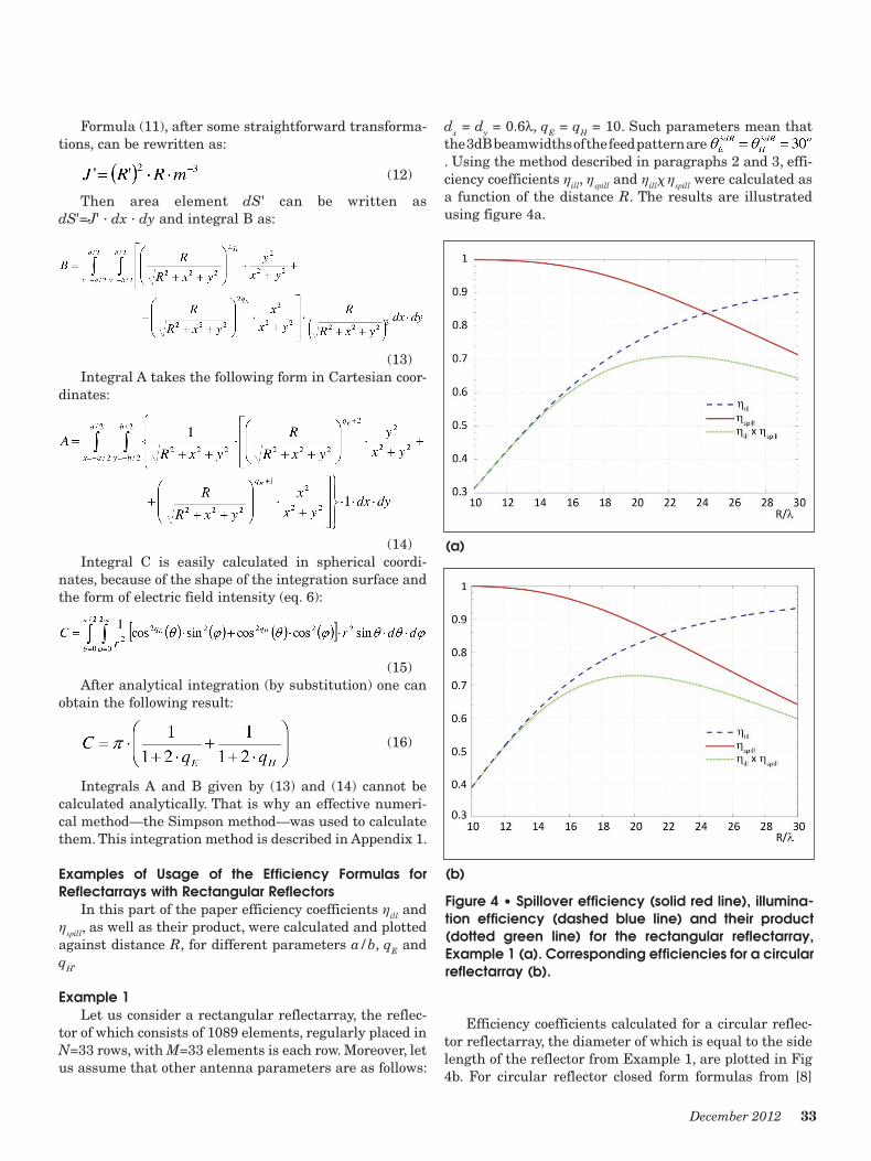
dx = dy = 0.6l, qE = qH = 10. Such parameters mean that the 3dB beamwidths of the feed pattern are . Using the method described in paragraphs 2 and 3, effi-ciency coefficients ηill, ηspill and ηillx ηspill were calculated as a function of the distance R. The results are illustrated using figure 4a.
Efficiency coefficients calculated for a circular reflec-tor reflectarray, the diameter of which is equal to the side length of the reflector from Example 1, are plotted in Fig 4b. For circular reflector closed form formulas from [8]
(a)
(b)
Figure 4 • Spillover efficiency (solid red line), illumina-tion efficiency (dashed blue line) and their product (dotted green line) for the rectangular reflectarray, Example 1 (a). Corresponding efficiencies for a circular reflectarray (b).

34 High Frequency Electronics
High Frequency Design
Reflectarray Antennas
were used. A short comparison of Fig. 4a and Fig. 4b leads to the conclusion that maximum efficiency (defined as the product of ηill and ηspill) for rectangular reflectarray amounts to 0.71 and occurs for R = 22.5l, whereas for circular reflectarray the efficiency is a little higher and goes up to 0.73 for R = 20l.
It is also worth mentioning that for a given feed-reflector distance R, the illumination efficiency is always higher (closer to 1.0) for a circular reflectarray than for its rectangular equivalent. Such conclusion becomes evi-dent when the shape of the reflectors and cross-section of the feed pattern are compared, showing that the corners of rectangular reflector are under-illuminated. On the contrary, spillover efficiency is always higher for rectan-gular reflectarray than for the circular one, assuming the same feed-reflector distance. This in turn may be explained by a bigger geometric area of the rectangular reflector, which has better “shielding” properties thanks to its corners.
Despite of these discrepancies, closed form formulas derived for circular reflectarrays may be used for square reflectarrays, at initial steps of design, provided that feed parameters are the same for circular and square reflec-tarray and the diameter of the circular reflector is equal to the side length of the square reflector. Under such cir-cumstances the maximum efficiency of square reflectar-ray, calculated using closed form formulas (derived for circular reflectarray) is only a few percent higher (up to 5%) than the maximum efficiency calculated using the method from paragraphs 1 and 2.
Example 2Let us now consider a reflectarray antenna with its
reflector parameters unchanged from Example 1, but with a feed pattern described by qE = qH = 3, which means that its 3dB beamwidths are . Again, the presented formulas were utilized in order to calculate reflectarray efficiencies. The results are gathered in Figure 5.
Similarly to Example 1, efficiency coefficients calcu-lated for a circular reflector reflectarray, the diameter of which is equal to the side length of the reflector from Example 2, are plotted in Fig 5b. This time the maxi-mum efficiency amounts to 0.59 for R = 13.5l in case of a rectangular reflectarray. Meanwhile, for a circular reflectarray, the maximum efficiency is 0.60 for R = 12l. Other conclusions are similar to those formulated in Example 1.
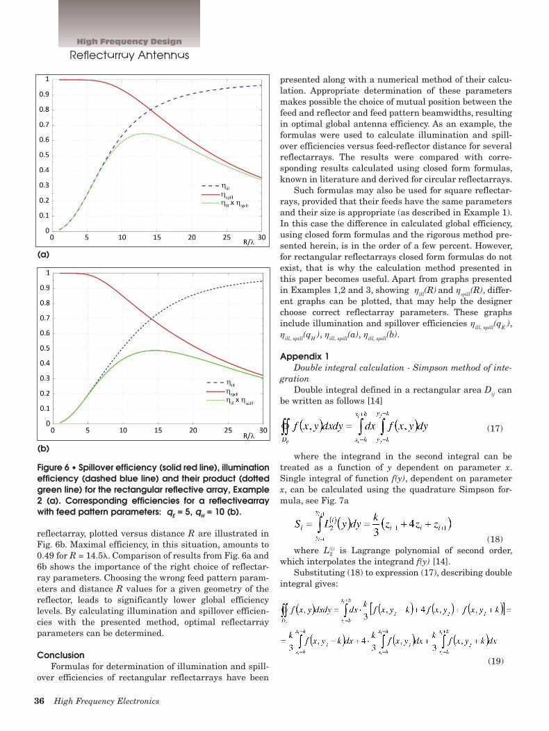
Example 3In the last example the formulas were used to calcu-
late efficiencies for a rectangular (non-square) reflectar-ray. Let us assume that the antenna reflector consists of 561 reflectarray elements organized in N = 33 rows, with M = 17 elements is each row. Other reflectarray parame-
ters are as follows: dx = dy = 0.6l, qE = 10,qH = 5. The 3dB beamwidths of the feed pattern are . Calculated efficiencies plotted versus distance R are illustrated in Fig. 6
Maximal efficiency, again defined as ηspillxηspill, amounts to 0.65, for R = 13.2l. It is worth mentioning that in the present example efficiencies cannot be evaluated using closed form formulas (similar to Example 1 and 2), because the shape of the reflector is rectangular and feed pattern beamwidths are different in both principal planes.
For comparison, a rectangular reflectarray was ana-lyzed with different feed pattern, shape of which is defined by qE = 5, qH = 10. Efficiencies calculated for this
(a)
(b)
Figure 5 • Spillover efficiency (solid red line), illumina-tion efficiency (dashed blue line) and their product (dotted green line) for the rectangular reflectivearray, Example 2 (a). Corresponding efficiencies for a circular reflectarray (b).
36 High Frequency Electronics
High Frequency Design
Reflectarray Antennas
reflectarray, plotted versus distance R are illustrated in Fig. 6b. Maximal efficiency, in this situation, amounts to 0.49 for R = 14.5l. Comparison of results from Fig. 6a and 6b shows the importance of the right choice of reflectar-ray parameters. Choosing the wrong feed pattern param-eters and distance R values for a given geometry of the reflector, leads to significantly lower global efficiency levels. By calculating illumination and spillover efficien-cies with the presented method, optimal reflectarray parameters can be determined.
ConclusionFormulas for determination of illumination and spill-
over efficiencies of rectangular reflectarrays have been
presented along with a numerical method of their calcu-lation. Appropriate determination of these parameters makes possible the choice of mutual position between the feed and reflector and feed pattern beamwidths, resulting in optimal global antenna efficiency. As an example, the formulas were used to calculate illumination and spill-over efficiencies versus feed-reflector distance for several reflectarrays. The results were compared with corre-sponding results calculated using closed form formulas, known in literature and derived for circular reflectarrays.
Such formulas may also be used for square reflectar-rays, provided that their feeds have the same parameters and their size is appropriate (as described in Example 1). In this case the difference in calculated global efficiency, using closed form formulas and the rigorous method pre-sented herein, is in the order of a few percent. However, for rectangular reflectarrays closed form formulas do not exist, that is why the calculation method presented in this paper becomes useful. Apart from graphs presented in Examples 1,2 and 3, showing ηill(R) and ηspill(R), differ-ent graphs can be plotted, that may help the designer choose correct reflectarray parameters. These graphs include illumination and spillover efficiencies ηill, spill(qE ), ηill, spill(qH ), ηill, spill(a), ηill, spill(b).
Appendix 1Double integral calculation - Simpson method of inte-
grationDouble integral defined in a rectangular area Dij can
be written as follows [14]
(17)
where the integrand in the second integral can be treated as a function of y dependent on parameter x. Single integral of function f(y), dependent on parameter x, can be calculated using the quadrature Simpson for-mula, see Fig. 7a
(18)where L(i) is Lagrange polynomial of second order,
which interpolates the integrand f(y) [14]. Substituting (18) to expression (17), describing double
integral gives:
(19)
(a)
(b)
Figure 6 • Spillover efficiency (solid red line), illumination efficiency (dashed blue line) and their product (dotted green line) for the rectangular reflective array, Example 2 (a). Corresponding efficiencies for a reflectivearray with feed pattern parameters: qE = 5, qH = 10 (b).
2

38 High Frequency Electronics
High Frequency Design
Reflectarray Antennas
Using the quadrature Simpson formula again, results in an expression called the Simpson cubature formula or the Simpson type mechanic cubature [14][15]. Finally, the value of double integral (15) over the rectangular area Dij can be written as [14][15]:
If the integration area D is large, it is divided into n 3 m equal, sufficiently small sub–areas Dij, with i = 1, 2, 3, ..., n, j = 1, 2, 3, ..., m, and their sides parallel to x and y axes. The values of the integral are calculated over every sub–areas Dij and then summed to give the value of the integral over the whole integration area D.
About the Author:Michał ŻŻebrowski received his M.S. degree in
Electronic Engineering from Warsaw University of Technology (in Polish: Politechnika Warszawska), Warsaw, Poland, in 2007. He has been involved with Microwave Devices Dept. of the Bumar Elektronia SA and Telecommunications Research Institute, Warsaw, Poland, since 2007. His current research interests include antenna array systems, especially reflectarray antennas and passive microwave components.
References:[1] Berry D., Malech R., Kennedy W., The reflectarray anten-
na, IEEE Transactions on Antennas and Propagation, November 1963,Vol. 11, Issue 6, pp. 645-651.
[2] Huang J., Capabilities of printed reflectarray antennas. IEEE International Symposium on Phased Array Systems and Technology, October 1996, pp. 131-134.
[3] Huang J., Hodges R., Zawadzki M., Rengarajan S., Han C., Chang K., Recent development of printed reflectarrays at JPL, Proceedings of URSI GA, October 2005.
[4] Goldsmith P. F., Radiation patterns of circular apertures with Gaussian illumination, International Journal of Infrared and Millimeter Waves, Vol. 8, No. 7, 1987 p. 6
[5] Silver S., Microwave antenna theory and design, McGraw- Hill, 1949, p.177.
[6] Rudge A. W., Milne K., et. al., The Handbook of Antenna Design, vol. 1, London, Peter Peregrinus Ltd., 1982, pp.169-171.
[7] Yu A., Yang F., Elsherbeni A., et. al., Aperture efficiency of reflectarray antennas, Microwave and Optical Technology Letters / Vol. 52, No. 2, February 2012, pp. 367-368.
[8] Huang J., Analysis of microstrip reflectarray antenna for microspacecraft applications, TDA Progress Report 42-120, February 1995, pp. 158-160.
[9] Huang J., Encinar J. A., Reflectarray Antennas, IEEE Press, John Wiley & Sons Inc, 2008, p. 87.
[10] Pozar D. M., Targonski S. D., Syrigos H. D., Design of mil-limeter wave microstrip reflectarrays, IEEE Transactions on Antennas and Propagation, Vol. 45, No. 2, February 1997, p. 209
[11] Rosloniec S., Fundamental Numerical Methods for Electrical Engineering, Springer-Verlag, Berlin, 2008, ch. 5
[12] Lo Y.T., Lee S.W., Antenna Handbook Vol. 1: Fundamentals and Mathematical Techniques, Chapman & Hall, 1993, p. 1-28.
[13] Larson R., Edwards B., Multivariable Calculus, 9th Ed.”, Brooks Cole, 2010, ch. 14.8
[14] Rosloniec S., Fundamental Numerical Methods for Electrical Engineering, Springer-Verlag, Berlin, 2008, ch. 5.
[15] Mathews J. H., Fink K. D., Numerical Methods using Matlab, Prentice Hall, Upper Saddle River, 1999, 3rd ed., ch. 7.
38 High Frequency Electronics
Figure 7 • Integration areas in the Simpson method.
(a)
(b)
Related Documents