Illinois Tollway Supplemental Specifications to the Illinois Department of Transportation Standard Specifications for Road and Bridge Construction Adopted April 1, 2016 Issued March 23, 2020 The Illinois State Toll Highway Authority

Welcome message from author
This document is posted to help you gain knowledge. Please leave a comment to let me know what you think about it! Share it to your friends and learn new things together.
Transcript
Illinois Tollway Supplemental Specifications
to the
Illinois Department of Transportation
Standard Specifications for Road and Bridge
Construction
Adopted April 1, 2016
Issued March 23, 2020
The Illinois State Toll Highway Authority

March 2020 | Illinois Tollway | i
INTRODUCTION
This publication contains a copy of ILLINOIS TOLLWAY SUPPLEMENTAL SPECIFICATIONS. The ILLINOIS TOLLWAY SUPPLEMENTAL SPECIFICATIONS contained herein supplement the
Illinois Department of Transportation Standard Specifications for Road and Bridge Construction Adopted April 1, 2016. The ILLINOIS TOLLWAY SUPPLEMENTAL SPECIFICATIONS are applicable to and included, by reference in, all contracts advertised and awarded by the Illinois Tollway.
Spec. Section Page No.
March 2020 | Illinois Tollway | ii
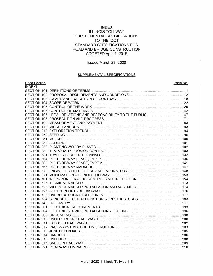
INDEX ILLINOIS TOLLWAY
SUPPLEMENTAL SPECIFICATIONS TO THE IDOT
STANDARD SPECIFICATIONS FOR ROAD AND BRIDGE CONSTRUCTION
ADOPTED April 1, 2016
Issued March 23, 2020
SUPPLEMENTAL SPECIFICATIONS Spec Section Page No, INDEX ii SECTION 101. DEFINITIONS OF TERMS ................................................................................................... 1 SECTION 102. PROPOSAL REQUIREMENTS AND CONDITIONS ......................................................... 12 SECTION 103. AWARD AND EXECUTION OF CONTRACT .................................................................... 18 SECTION 104. SCOPE OF WORK ............................................................................................................ 22 SECTION 105. CONTROL OF THE WORK ............................................................................................... 29 SECTION 106. CONTROL OF MATERIALS .............................................................................................. 42 SECTION 107. LEGAL RELATIONS AND RESPONSIBILITY TO THE PUBLIC ...................................... 47 SECTION 108. PROSECUTION AND PROGRESS .................................................................................. 71 SECTION 109. MEASUREMENT AND PAYMENT .................................................................................... 83 SECTION 110. MISCELLANEOUS ............................................................................................................ 93 SECTION 213. EXPLORATION TRENCH ................................................................................................. 94 SECTION 250. SEEDING ........................................................................................................................... 96 SECTION 251. MULCH ............................................................................................................................ 100 SECTION 252. SODDING ........................................................................................................................ 101 SECTION 253. PLANTING WOODY PLANTS ......................................................................................... 102 SECTION 280. TEMPORARY EROSION CONTROL .............................................................................. 103 SECTION 631. TRAFFIC BARRIER TERMINALS ................................................................................... 132 SECTION 664. RIGHT-OF-WAY FENCE, TYPE 1................................................................................... 136 SECTION 665. RIGHT-OF-WAY FENCE, TYPE 2................................................................................... 141 SECTION 666. RIGHT-OF-WAY MARKERS ........................................................................................... 147 SECTION 670. ENGINEERS FIELD OFFICE AND LABORATORY ........................................................ 148 SECTION 671. MOBILIZATION – ILLINOIS TOLLWAY .......................................................................... 153 SECTION 701. WORK ZONE TRAFFIC CONTROL AND PROTECTION .............................................. 154 SECTION 725. TERMINAL MARKER ...................................................................................................... 173 SECTION 726. MILEPOST MARKER INSTALLATION AND ASSEMBLY .............................................. 174 SECTION 727. SIGN SUPPORT - BREAKAWAY .................................................................................... 176 SECTION 733. OVERHEAD SIGN STRUCTURES ................................................................................. 177 SECTION 734. CONCRETE FOUNDATIONS FOR SIGN STRUCTURES ............................................. 183 SECTION 740. ITS GANTRY……………………………………………………………………………………190 SECTION 801. ELECTRICAL REQUIREMENTS ..................................................................................... 193 SECTION 804. ELECTRIC SERVICE INSTALLATION - LIGHTING ....................................................... 196 SECTION 806. GROUNDING ................................................................................................................... 198 SECTION 810. UNDERGROUND RACEWAYS....................................................................................... 200 SECTION 811. EXPOSED RACEWAYS .................................................................................................. 202 SECTION 812. RACEWAYS EMBEDDED IN STRUCTURE ................................................................... 203 SECTION 813. JUNCTION BOXES ......................................................................................................... 205 SECTION 814. HANDHOLE ..................................................................................................................... 206 SECTION 816. UNIT DUCT ...................................................................................................................... 208 SECTION 817. CABLE IN RACEWAY ..................................................................................................... 209 SECTION 821. ROADWAY LUMINAIRES ............................................................................................... 210
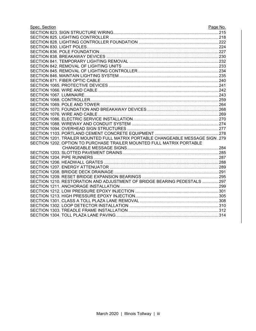
Spec. Section Page No.
March 2020 | Illinois Tollway | iii
SECTION 823. SIGN STRUCTURE WIRING........................................................................................... 215 SECTION 825. LIGHTING CONTROLLER .............................................................................................. 218 SECTION 828. LIGHTING CONTROLLER FOUNDATION ..................................................................... 222 SECTION 830. LIGHT POLES.................................................................................................................. 224 SECTION 836. POLE FOUNDATION ....................................................................................................... 227 SECTION 838. BREAKAWAY DEVICES ................................................................................................. 230 SECTION 841. TEMPORARY LIGHTING REMOVAL ............................................................................. 232 SECTION 842. REMOVAL OF LIGHTING UNITS ................................................................................... 233 SECTION 845. REMOVAL OF LIGHTING CONTROLLER ...................................................................... 234 SECTION 846. MAINTAIN LIGHTING SYSTEM ...................................................................................... 235 SECTION 871. FIBER OPTIC CABLE ...................................................................................................... 240 SECTION 1065. PROTECTIVE DEVICES ............................................................................................... 241 SECTION 1066. WIRE AND CABLE ........................................................................................................ 242 SECTION 1067. LUMINAIRE.................................................................................................................... 243 SECTION 1068. CONTROLLER............................................................................................................... 259 SECTION 1069. POLE AND TOWER ...................................................................................................... 264 SECTION 1070. FOUNDATION AND BREAKAWAY DEVICES .............................................................. 268 SECTION 1076. WIRE AND CABLE ........................................................................................................ 269 SECTION 1086. ELECTRIC SERVICE INSTALLATION .......................................................................... 270 SECTION 1088. WIREWAY AND CONDUIT SYSTEM ........................................................................... 274 SECTION 1094. OVERHEAD SIGN STRUCTURES ............................................................................... 277 SECTION 1103. PORTLAND CEMENT CONCRETE EQUIPMENT ....................................................... 278 SECTION 1201. TRAILER MOUNTED FULL MATRIX PORTABLE CHANGEABLE MESSAGE SIGN . 279 SECTION 1202. OPTION TO PURCHASE TRAILER MOUNTED FULL MATRIX PORTABLE
CHANGEABLE MESSAGE SIGNS ............................................................................... 284 SECTION 1203. SLOTTED PAVEMENT DRAINS ................................................................................... 285 SECTION 1204. PIPE RUNNERS ............................................................................................................ 287 SECTION 1206. HEADWALL GRATES ................................................................................................... 288 SECTION 1207. ENERGY ATTENUATOR .............................................................................................. 289 SECTION 1208. BRIDGE DECK DRAINAGE .......................................................................................... 291 SECTION 1209. RESET BRIDGE EXPANSION BEARINGS .................................................................. 295 SECTION 1210. RESTORATION AND ADJUSTMENT OF BRIDGE BEARING PEDESTALS .............. 297 SECTION 1211. ANCHORAGE INSTALLATION ..................................................................................... 299 SECTION 1212. LOW PRESSURE EPOXY INJECTION ........................................................................ 301 SECTION 1213. HIGH PRESSURE EPOXY INJECTION ........................................................................ 305 SECTION 1301. CLASS A TOLL PLAZA LANE REMOVAL .................................................................... 308 SECTION 1302. LOOP DETECTOR INSTALLATION ............................................................................. 310 SECTION 1303. TREADLE FRAME INSTALLATION .............................................................................. 312 SECTION 1304. TOLL PLAZA LANE PAVING ......................................................................................... 314
March 2020 | Illinois Tollway | 1
Illinois State Toll Highway Authority
SUPPLEMENTAL SPECIFICATION FOR
SECTION 101. DEFINITIONS OF TERMS
Issued April 1, 2016 Revised March 23, 2020
This Supplemental Specification amends and supersedes the provisions of the Illinois Department of
Transportation Standard Specifications for Road and Bridge Construction, adopted April 1, 2016 and shall be construed to be a part thereof, superseding any conflicting provisions thereof applicable to the work under the contract.
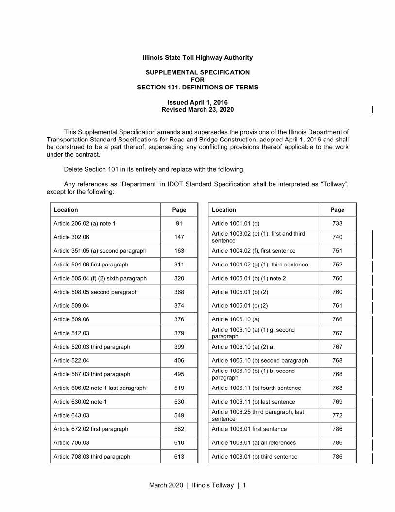
Delete Section 101 in its entirety and replace with the following. Any references as “Department” in IDOT Standard Specification shall be interpreted as “Tollway”,
except for the following:
Location Page
Article 206.02 (a) note 1 91
Article 302.06 147
Article 351.05 (a) second paragraph 163
Article 504.06 first paragraph 311
Article 505.04 (f) (2) sixth paragraph 320
Article 508.05 second paragraph 368
Article 509.04 374
Article 509.06 376
Article 512.03 379
Article 520.03 third paragraph 399
Article 522.04 406
Article 587.03 third paragraph 495
Article 606.02 note 1 last paragraph 519
Article 630.02 note 1 530
Article 643.03 549
Article 672.02 first paragraph 582
Article 706.03 610
Article 708.03 third paragraph 613
Location Page
Article 1001.01 (d) 733
Article 1003.02 (e) (1), first and third sentence
740
Article 1004.02 (f), first sentence 751
Article 1004.02 (g) (1), third sentence 752
Article 1005.01 (b) (1) note 2 760
Article 1005.01 (b) (2) 760
Article 1005.01 (c) (2) 761
Article 1006.10 (a) 766
Article 1006.10 (a) (1) g, second paragraph
767
Article 1006.10 (a) (2) a. 767
Article 1006.10 (b) second paragraph 768
Article 1006.10 (b) (1) b, second paragraph
768
Article 1006.11 (b) fourth sentence 768
Article 1006.11 (b) last sentence 769
Article 1006.25 third paragraph, last sentence
772
Article 1008.01 first sentence 786
Article 1008.01 (a) all references 786
Article 1008.01 (b) third sentence 786
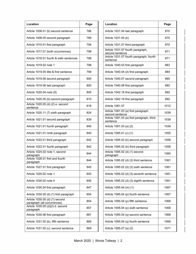
March 2020 | Illinois Tollway | 2
Location Page
Article 1008.01 (b) second sentence 786
Article 1008.05 second paragraph 789
Article 1010.01 first paragraph 794
Article 1017.01 (both occurrences) 798
Article 1018.01 fourth & sixth sentences 798
Article 1019.02 note 1 798
Article 1019.05 title & first sentence 799
Article 1019.06 second paragraph 800
Article 1019.06 last paragraph 800
Article 1020.04 note (9) 805
Article 1020.05 (b) second paragraph 810
Article 1020.05 (d) (2) e. second sentence
818
Article 1020.11 (7) sixth paragraph 824
Article 1021.01 second paragraph 839
Article 1021.01 fourth paragraph 840
Article 1021.01 ninth paragraph 840
Article 1022.01 third paragraph 842
Article 1022.01 fourth paragraph 842
Article 1024.02 note 1, second paragraph
844
Article 1026.01 first and fourth paragraph
844
Article 1027.01 first paragraph 845
Article 1029.02 note 1 845
Article 1030.02 note 4 846
Article 1030.04 first paragraph 847
Article 1030.05 (d) (1) first paragraph 854
Article 1030.05 (d) (1) second paragraph (all occurrences)
854
Article 1030.05 (d)(2) d. second paragraph
857
Article 1030.08 first paragraph 867
Article 1031.02 (b), fifth sentence 869
Article 1031.02 (c), second sentence 869
Location Page
Article 1031.04 last paragraph 870
Article 1031.05 (b) 870
Article 1031.07 third paragraph 870
Article 1031.07 fourth paragraph, second sentence
871
Article 1031.07 fourth paragraph, fourth sentence
871
Article 1040.03 first paragraph 883
Article 1040.04 (d) first paragraph 884
Article 1040.07 second paragraph 885
Article 1040.08 first paragraph 885
Article 1042.18 first paragraph 892
Article 1042.19 first paragraph 892
Article 1081.07 1012
Article 1091.03 (a) first paragraph, second sentence
1039
Article 1091.03 (a) first paragraph, third sentence
1039
Article 1091.03 (a) (2) 1039
Article 1095.01 (c) (1) 1055
Article 1095.02 (b) second paragraph 1058
Article 1095.02 (b) third paragraph 1058
Article 1095.02 (d) (1) second paragraph
1060
Article 1095.02 (d) (3) third sentence 1061
Article 1095.02 (d) (3) sixth sentence 1061
Article 1095.02 (d) (3) seventh sentence 1061
Article 1095.02 (d) (3) eighth sentence 1061
Article 1095.04 (m) (1) 1067
Article 1095.04 (p) fourth sentence 1067
Article 1095.04 (p) fifth sentence 1068
Article 1095.04 (p) sixth sentence 1068
Article 1095.04 (q) second sentence 1068
Article 1095.04 (q) fourth sentence 1068
Article 1095.07 (a) (2) 1071
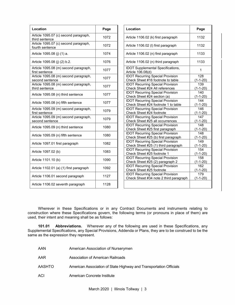
March 2020 | Illinois Tollway | 3
Location Page
Article 1095.07 (c) second paragraph, third sentence
1072
Article 1095.07 (c) second paragraph, fourth sentence
1072
Article 1095.08 (j) (1) a. 1074
Article 1095.08 (j) (2) b.2. 1076
Article 1095.08 (m) second paragraph, first sentence
1077
Article 1095.08 (m) second paragraph, second sentence
1077
Article 1095.08 (m) second paragraph, third sentence
1077
Article 1095.08 (n) third sentence 1077
Article 1095.08 (n) fifth sentence 1077
Article 1095.09 (m) second paragraph, first sentence
1079
Article 1095.09 (m) second paragraph, second sentence
1079
Article 1095.09 (n) third sentence 1080
Article 1095.09 (n) fifth sentence 1080
Article 1097.01 first paragraph 1082
Article 1097.02 (b) 1083
Article 1101.10 (b) 1090
Article 1102.01 (a) (1) first paragraph 1092
Article 1106.01 second paragraph 1127
Article 1106.02 seventh paragraph 1128
Location Page
Article 1106.02 (k) first paragraph 1132
Article 1106.02 (l) first paragraph 1132
Article 1106.02 (n) first paragraph 1133
Article 1106.02 (n) third paragraph 1133
IDOT Supplemental Specifications, Article 106.08(d)
1
IDOT Recurring Special Provision Check Sheet #16 footnote to table
128 (1-1-20)
IDOT Recurring Special Provision Check Sheet #24 All references
139 (1-1-20)
IDOT Recurring Special Provision Check Sheet #24 section (a)
140 (1-1-20)
IDOT Recurring Special Provision Check Sheet #24 footnote 1 to table
144 (1-1-20)
IDOT Recurring Special Provision Check Sheet #24 footnote
146 (1-1-20)
IDOT Recurring Special Provision Check Sheet #25 all occurrences
147 (1-1-20)
IDOT Recurring Special Provision Check Sheet #25 first paragraph
148 (1-1-20)
IDOT Recurring Special Provision Check Sheet #25 (b) first paragraph
148 (1-1-20)
IDOT Recurring Special Provision Check Sheet #25 (1) third paragraph
149 (1-1-20)
IDOT Recurring Special Provision Check Sheet #25 footnote 1
154 (1-1-20)
IDOT Recurring Special Provision Check Sheet #25 (2) paragraph 2
158 (1-1-20)
IDOT Recurring Special Provision Check Sheet #25 footnote
162 (1-1-20)
IDOT Recurring Special Provision Check Sheet #34 note 2 third paragraph
179 (1-1-20)
Wherever in these Specifications or in any Contract Documents and instruments relating to
construction where these Specifications govern, the following terms (or pronouns in place of them) are used, their intent and meaning shall be as follows:
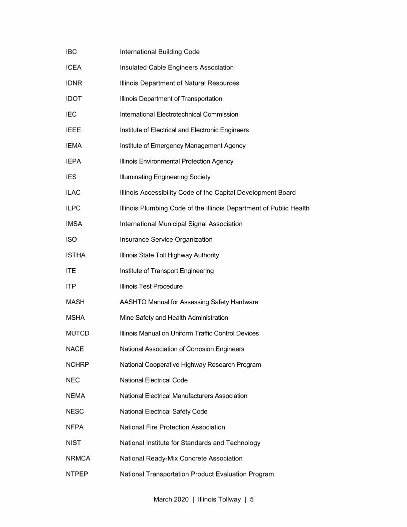
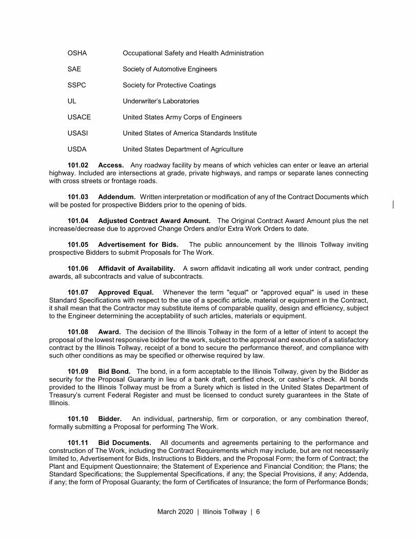
101.01 Abbreviations. Wherever any of the following are used in these Specifications, any
Supplemental Specifications, any Special Provisions, Addenda or Plans, they are to be construed to be the same as the expression they represent.
AAN American Association of Nurserymen
AAR Association of American Railroads
AASHTO American Association of State Highway and Transportation Officials
ACI American Concrete Institute
March 2020 | Illinois Tollway | 4
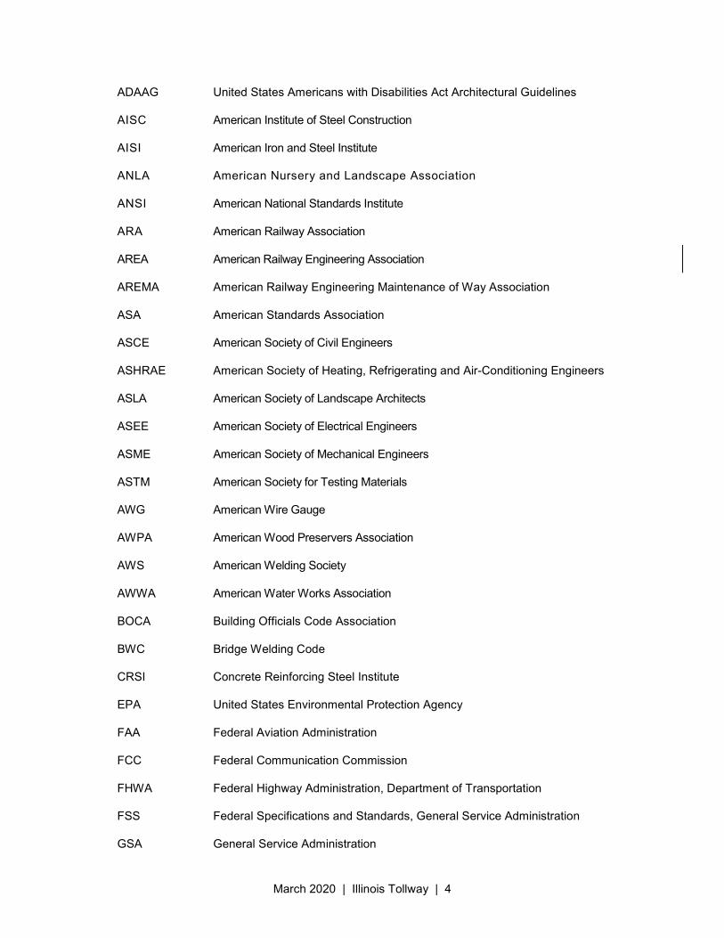
ADAAG United States Americans with Disabilities Act Architectural Guidelines
AISC American Institute of Steel Construction
AISI American Iron and Steel Institute
ANLA American Nursery and Landscape Association
ANSI American National Standards Institute
ARA American Railway Association
AREA American Railway Engineering Association
AREMA American Railway Engineering Maintenance of Way Association
ASA American Standards Association
ASCE American Society of Civil Engineers
ASHRAE American Society of Heating, Refrigerating and Air-Conditioning Engineers
ASLA American Society of Landscape Architects
ASEE American Society of Electrical Engineers
ASME American Society of Mechanical Engineers
ASTM American Society for Testing Materials
AWG American Wire Gauge
AWPA American Wood Preservers Association
AWS American Welding Society
AWWA American Water Works Association
BOCA Building Officials Code Association
BWC Bridge Welding Code
CRSI Concrete Reinforcing Steel Institute
EPA United States Environmental Protection Agency
FAA Federal Aviation Administration
FCC Federal Communication Commission
FHWA Federal Highway Administration, Department of Transportation
FSS Federal Specifications and Standards, General Service Administration
GSA General Service Administration
March 2020 | Illinois Tollway | 5
IBC International Building Code
ICEA Insulated Cable Engineers Association
IDNR Illinois Department of Natural Resources
IDOT Illinois Department of Transportation
IEC International Electrotechnical Commission
IEEE Institute of Electrical and Electronic Engineers
IEMA Institute of Emergency Management Agency
IEPA Illinois Environmental Protection Agency
IES Illuminating Engineering Society
ILAC Illinois Accessibility Code of the Capital Development Board
ILPC Illinois Plumbing Code of the Illinois Department of Public Health
IMSA International Municipal Signal Association
ISO Insurance Service Organization
ISTHA Illinois State Toll Highway Authority
ITE Institute of Transport Engineering
ITP Illinois Test Procedure
MASH AASHTO Manual for Assessing Safety Hardware
MSHA Mine Safety and Health Administration
MUTCD Illinois Manual on Uniform Traffic Control Devices
NACE National Association of Corrosion Engineers
NCHRP National Cooperative Highway Research Program
NEC National Electrical Code
NEMA National Electrical Manufacturers Association
NESC National Electrical Safety Code
NFPA National Fire Protection Association
NIST National Institute for Standards and Technology
NRMCA National Ready-Mix Concrete Association
NTPEP National Transportation Product Evaluation Program
March 2020 | Illinois Tollway | 6
OSHA Occupational Safety and Health Administration
SAE Society of Automotive Engineers
SSPC Society for Protective Coatings
UL Underwriter’s Laboratories
USACE United States Army Corps of Engineers
USASI United States of America Standards Institute
USDA United States Department of Agriculture
101.02 Access. Any roadway facility by means of which vehicles can enter or leave an arterial highway. Included are intersections at grade, private highways, and ramps or separate lanes connecting with cross streets or frontage roads.
101.03 Addendum. Written interpretation or modification of any of the Contract Documents which will be posted for prospective Bidders prior to the opening of bids.
101.04 Adjusted Contract Award Amount. The Original Contract Award Amount plus the net increase/decrease due to approved Change Orders and/or Extra Work Orders to date.
101.05 Advertisement for Bids. The public announcement by the Illinois Tollway inviting prospective Bidders to submit Proposals for The Work.
101.06 Affidavit of Availability. A sworn affidavit indicating all work under contract, pending awards, all subcontracts and value of subcontracts.
101.07 Approved Equal. Whenever the term "equal" or "approved equal" is used in these Standard Specifications with respect to the use of a specific article, material or equipment in the Contract, it shall mean that the Contractor may substitute items of comparable quality, design and efficiency, subject to the Engineer determining the acceptability of such articles, materials or equipment.
101.08 Award. The decision of the Illinois Tollway in the form of a letter of intent to accept the proposal of the lowest responsive bidder for the work, subject to the approval and execution of a satisfactory contract by the Illinois Tollway, receipt of a bond to secure the performance thereof, and compliance with such other conditions as may be specified or otherwise required by law.
101.09 Bid Bond. The bond, in a form acceptable to the Illinois Tollway, given by the Bidder as security for the Proposal Guaranty in lieu of a bank draft, certified check, or cashier’s check. All bonds provided to the Illinois Tollway must be from a Surety which is listed in the United States Department of Treasury’s current Federal Register and must be licensed to conduct surety guarantees in the State of Illinois.
101.10 Bidder. An individual, partnership, firm or corporation, or any combination thereof, formally submitting a Proposal for performing The Work.
101.11 Bid Documents. All documents and agreements pertaining to the performance and construction of The Work, including the Contract Requirements which may include, but are not necessarily limited to, Advertisement for Bids, Instructions to Bidders, and the Proposal Form; the form of Contract; the Plant and Equipment Questionnaire; the Statement of Experience and Financial Condition; the Plans; the Standard Specifications; the Supplemental Specifications, if any; the Special Provisions, if any; Addenda, if any; the form of Proposal Guaranty; the form of Certificates of Insurance; the form of Performance Bonds;
March 2020 | Illinois Tollway | 7
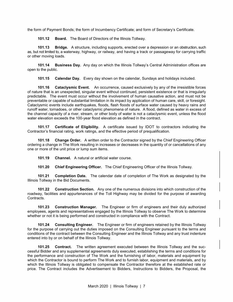
the form of Payment Bonds; the form of Incumbency Certificate; and form of Secretary’s Certificate.
101.12 Board. The Board of Directors of the Illinois Tollway.
101.13 Bridge. A structure, including supports, erected over a depression or an obstruction, such as, but not limited to, a waterway, highway, or railway, and having a track or passageway for carrying traffic or other moving loads.
101.14 Business Day. Any day on which the Illinois Tollway’s Central Administration offices are open to the public.
101.15 Calendar Day. Every day shown on the calendar, Sundays and holidays included.
101.16 Cataclysmic Event. An occurrence, caused exclusively by any of the irresistible forces of nature that is an unexpected, singular event without continued, persistent existence or that is irregularly predictable. The event must occur without the involvement of human causative action, and must not be preventable or capable of substantial limitation in its impact by application of human care, skill, or foresight. Cataclysmic events include earthquakes, floods, flash floods of surface water caused by heavy rains and runoff water, tornadoes, or other cataclysmic phenomena of nature. A flood, defined as water in excess of the channel capacity of a river, stream, or other body of water is not a cataclysmic event, unless the flood water elevation exceeds the 100-year flood elevation as defined in the contract.
101.17 Certificate of Eligibility. A certificate issued by IDOT to contractors indicating the Contractor’s financial rating, work ratings, and the effective period of prequalification.
101.18 Change Order. A written order to the Contractor signed by the Chief Engineering Officer ordering a change in The Work resulting in increases or decreases in the quantity of or cancellations of any one or more of the unit price or lump sum items.
101.19 Channel. A natural or artificial water course.
101.20 Chief Engineering Officer. The Chief Engineering Officer of the Illinois Tollway.
101.21 Completion Date. The calendar date of completion of The Work as designated by the Illinois Tollway in the Bid Documents.
101.22 Construction Section. Any one of the numerous divisions into which construction of the roadway, facilities and appurtenances of the Toll Highway may be divided for the purpose of awarding Contracts.
101.23 Construction Manager. The Engineer or firm of engineers and their duly authorized employees, agents and representatives engaged by the Illinois Tollway to observe The Work to determine whether or not it is being performed and constructed in compliance with the Contract.
101.24 Consulting Engineer. The Engineer or firm of engineers retained by the Illinois Tollway for the purpose of carrying out the duties imposed on the Consulting Engineer pursuant to the terms and conditions of the contract between the Consulting Engineer and the Illinois Tollway and any trust indenture entered into by or on behalf of the Illinois Tollway.
101.25 Contract. The written agreement executed between the Illinois Tollway and the suc-cessful Bidder and any supplemental agreements duly executed, establishing the terms and conditions for the performance and construction of The Work and the furnishing of labor, materials and equipment by which the Contractor is bound to perform The Work and to furnish labor, equipment and materials, and by which the Illinois Tollway is obligated to compensate the Contractor therefore at the established rate or price. The Contract includes the Advertisement to Bidders, Instructions to Bidders, the Proposal, the
March 2020 | Illinois Tollway | 8
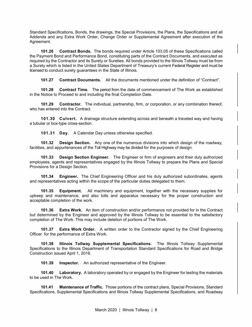
Standard Specifications, Bonds, the drawings, the Special Provisions, the Plans, the Specifications and all Addenda and any Extra Work Order, Change Order or Supplemental Agreement after execution of the Agreement.
101.26 Contract Bonds. The bonds required under Article 103.05 of these Specifications called the Payment Bond and Performance Bond, constituting parts of the Contract Documents, and executed as required by the Contractor and its Surety or Sureties. All bonds provided to the Illinois Tollway must be from a Surety which is listed in the United States Department of Treasury’s current Federal Register and must be licensed to conduct surety guarantees in the State of Illinois.
101.27 Contract Documents. All the documents mentioned under the definition of “Contract”.
101.28 Contract Time. The period from the date of commencement of The Work as established in the Notice to Proceed to and including the final Completion Date.
101.29 Contractor. The individual, partnership, firm, or corporation, or any combination thereof, who has entered into the Contract.
101.30 Culvert. A drainage structure extending across and beneath a traveled way and having a tubular or box-type cross-section.
101.31 Day. A Calendar Day unless otherwise specified.
101.32 Design Section. Any one of the numerous divisions into which design of the roadway, facilities, and appurtenances of the Toll Highway may be divided for the purposes of design.
101.33 Design Section Engineer. The Engineer or firm of engineers and their duly authorized employees, agents and representatives engaged by the Illinois Tollway to prepare the Plans and Special Provisions for a Design Section.
101.34 Engineer. The Chief Engineering Officer and his duly authorized subordinates, agents and representatives acting within the scope of the particular duties delegated to them.
101.35 Equipment. All machinery and equipment, together with the necessary supplies for upkeep and maintenance, and also tolls and apparatus necessary for the proper construction and acceptable completion of the work.
101.36 Extra Work. An item of construction and/or performance not provided for in the Contract but determined by the Engineer and approved by the Illinois Tollway to be essential to the satisfactory completion of The Work. This may include deletion of portions of The Work.
101.37 Extra Work Order. A written order to the Contractor signed by the Chief Engineering Officer for the performance of Extra Work.
101.38 Illinois Tollway Supplemental Specifications. The Illinois Tollway Supplemental Specifications to the Illinois Department of Transportation Standard Specifications for Road and Bridge Construction issued April 1, 2016.
101.39 Inspector. An authorized representative of the Engineer.
101.40 Laboratory. A laboratory operated by or engaged by the Engineer for testing the materials to be used in The Work.
101.41 Maintenance of Traffic. Those portions of the contract plans, Special Provisions, Standard Specifications, Supplemental Specifications and Illinois Tollway Supplemental Specifications, and Roadway
March 2020 | Illinois Tollway | 9
Traffic Control and Communications Manual having to do with temporary traffic control.
101.42 Material. Any substance specified for use in the construction of The Work and its appurtenances.
101.43 Median. The portion of a divided highway separating the traveled ways for traffic in opposite directions.
101.44 Notice of Award. A written or electronic notice from the Chief of Contract Services to the apparent successful Bidder that the Illinois Tollway is planning to award the Contract to that Bidder. This notice will also establish the times and dates for contract signing and the pre-construction meeting.
101.45 Notice to Proceed. A written, electronic, or telegraphic notice from the Chief Engineering Officer to the Contractor that will be issued after the Board has approved the Contract, which notice designates the date for commencement of The Work by the Contractor pursuant to the terms and conditions of the Contract.
101.46 Original Contract Award Amount. The total amount of the Proposal, as awarded by the Board.
101.47 Pavement Structures. The combination of subbase, base course, and surface course placed on a subgrade to support traffic load and distribute it to the roadbed.
101.48 Pay Item. An item of work specifically described in any one or more of the Contract Documents for which a price, either a unit or lump sum, is therein provided including, but not limited to, all labor, equipment, and materials therein described.
101.49 Plans. The contract drawings, or exact reproductions thereof, bearing a stamp and signature of the Design Section Engineer which show the location, character, dimensions, and details of The Work. Contract drawings include, but are not limited to, the approved plans, profiles, typical cross sections, detail drawings, shop drawings, working drawings, layout drawings, supplemental drawings, Illinois Tollway Standard Drawings, and IDOT Highway Standards.
101.50 Proposal. The offer of the Bidder to construct and perform The Work, when made out and submitted on the prescribed Proposal Form, and properly signed.
101.51 Proposal Form. The approved form on which the Illinois Tollway requires formal bids to be submitted for the construction and performance of The Work.
101.52 Proposed Guaranty. The security furnished by the Bidder with the Proposal as guaranty that the Bidder will enter into, execute, and deliver the Contract and any and all documents constituting or required by the Contract.
101.53 Public Agency. Any public body whether local, state or federal charged by law with the responsibility of administering and/or controlling public facilities which may be affected by the construction or reconstruction of the roadway, facilities and appurtenances of the Toll Highway.
101.54 Public Road. Any road, highway, street, or alley or traveled way which is open, has been dedicated, or is otherwise legally available to public use, regardless of by whom or by what agency or division of government it be owned, controlled, or maintained; as used herein, the term does not include any Toll Highway operated or to be operated by the Illinois Tollway.
101.55 Railroad. The Railroad or Railway Company whose property is involved in the work.
101.56 Railroad Engineer. The Chief Engineer or Superintendent of the Railroad, or authorized
March 2020 | Illinois Tollway | 10
representative limited to the particular duties entrusted to him/her.
101.57 Regional Engineer. The Chief Engineering Officer of the Illinois Tollway.
101.58 Resident Engineer/Resident Technician. The authorized representative of the Engineer in immediate charge of the engineering details of a construction project.
101.59 Right-of-Way. A general term denoting land, property, or interests therein, acquired for or devoted to a highway.
101.60 Roadbed. The graded portion of a highway within side slopes, prepared as a foundation for the pavement structure and shoulders.
101.61 Roadside. A general term denoting the area adjoining the outer edge of the roadway. Extensive areas between the roadways of a divided highway may also be considered roadside.
101.62 Roadside Development. Those items necessary to the complete highway which provide for the preservation of landscape materials and features; the rehabilitation and protection against erosion of all areas disturbed by construction though seeding, sodding, mulching, and the placing of other ground covers; and such suitable planting and other improvements as may increase the effectiveness and enhance the appearance of the highway.
101.63 Roadway. The portion of the right-of-way within limits of construction.
101.64 Shoulder. The portion of the roadway contiguous with the traveled way for accommodation of stopped vehicles, emergency use, and lateral support of base and surface courses.
101.65 Special Provisions. Special clauses, directions, and requirements supplemental to these Illinois Tollway Supplemental Specifications, IDOT Supplemental Specifications and Recurring Special Provisions, and IDOT Standard Specifications, setting forth requirements peculiar to The Work included in the Bid Documents.
101.66 Specifications. The general term comprising the directions, provisions, instructions, and requirements contained herein as well as the Special Provisions, any Supplemental Specifications, and Addenda.
101.67 Standard Specifications. IDOT Standard Specifications for Road and Bridge Construction, latest edition.
101.68 Statement of Experience and Financial Condition. A statement prepared by the Bidder and submitted with its Proposal dated not more than 12 months prior to the Proposal that shall detail the Bidder’s experience in performing construction work similar to that for which it is submitting the Proposal and providing a statement, properly executed and certified by a certified public accountant, as to the financial condition of the Bidder according to generally accepted accounting principles, consistently applied. The statement shall be accompanied by a certified statement signed and certified by the Bidder as of the date of the Proposal that there has been no material adverse change to such statement.
101.69 Structure. Unless otherwise defined in the Specifications, structures shall comprise all objects constructed of materials other than earth, required by the contract to be built or to be removed, but not including surfacings, base courses, subbases, gutters, curbs, sidewalks, and driveway pavement.
101.70 Subcontractor. An individual, firm, partnership or corporation, or any combination thereof, who, with the written consent of the Engineer, assumes obligation for performing specified pay items.
101.71 Subgrade. The top surface of a roadbed upon which pavement structure and shoulders
March 2020 | Illinois Tollway | 11
are constructed.
101.72 Substructure. All of that part of the structure below the bearings of simple and continuous spans, skewbacks of arches and tops of footings of rigid frames, together with the backwalls, wing walls and wing protection railings.
101.73 Superintendent. The representative of the Contractor, present on The Work at all times during its progress, capable of reading and thoroughly understanding the Plans and Specifications, authorized to receive and fulfill instructions from the Engineer, and who shall supervise and direct construction and cross check the work for compliance with the Contractor’s Quality Control Manual
101.74 Superstructure. The entire structure except the substructure.
101.75 Supplemental Specifications. Additions and revisions to the Standard Specifications published by IDOT that are adopted subsequent to issuance of the Standard Specifications for Road and Bridge Construction.
101.76 Surety. The individual or entity, qualified to act as a surety in the State of Illinois and acceptable to the Illinois Tollway which issues the bonds required by the Illinois Tollway.
101.77 Traveled way. The portion of the roadway for the movement of vehicles, exclusive of shoulders and auxiliary lanes.
101.78 Toll Highway. The limited access highway built or proposed to be built by the Illinois Tollway, including all facilities and appurtenances thereto.
101.79 Tollway. The Illinois State Toll Highway Authority, or Illinois Tollway.
101.80 Utility. The privately, publicly, municipally, or cooperatively owned line, facility, or system for producing, transmitting, or distributing communications, cable television, power, electricity, light, heat, gas, oil, crude products, water, steam, or waste water. The term “utility” shall also mean the utility company, inclusive of any wholly owned or controlled subsidiary.
Utility as defined herein, includes street lighting systems, traffic signal systems, railroad warning device systems, or fire/police pre-emptors, or their collateral cables and conduit.
101.81 Work. Work shall mean the furnishing of all labor, material, tools, equipment, and other incidentals necessary or convenient to the successful completion of the project and carrying out of all duties and obligations imposed by the contract. Work may also be used in context to describe, in whole or in part, the completed facilities to be constructed, altered or removed, as detailed in the Contract. The Engineer will have exclusive authority to determine the intent and meaning of the usage of this term whenever it appears in the Contract.
March 2020 | Illinois Tollway | 12
Illinois State Toll Highway Authority
SUPPLEMENTAL SPECIFICATION FOR
SECTION 102. PROPOSAL REQUIREMENTS AND CONDITIONS
Issued April 1, 2016 Revised March 23, 2020
This Supplemental Specification amends and supersedes the provisions of the Illinois Department of Transportation Standard Specifications for Road and Bridge Construction, adopted April 1, 2016 and shall be construed to be a part thereof, superseding any conflicting provisions thereof applicable to the work under the contract.
Delete Section 102 in its entirety and replace with the following
102.01 Contents of Proposal. Bidders will be furnished with Bid Documents which shall include, but not be limited to, the Proposal Forms stating the location and description of The Work contemplated, the quantities of work to be performed and materials to be furnished, the amount of the Proposal Guaranty, and the date, time and place for the filing and opening of Proposals.
102.02 Furnishing of Addenda. A copy of each Addendum (if any) will be mailed or delivered by the Illinois Tollway to each person who buys from the Illinois Tollway one or more sets of Bid Documents and furnishes an address to the Illinois Tollway at the time of such purchase. Addenda will be issued no later than 72 hours prior to the date and time for opening Proposals. The Bidder shall acknowledge receipt of each Addendum prior to opening of the Proposals in the spaces provided in the Proposal Form.
102.03 Significance of Estimated Quantities. The estimated quantities of work to be done and materials to be furnished under these Specifications are provided in the Bid Documents. All quantities are to be considered as approximate and are to be used only for comparison purposes and as a basis for computing the Proposal Guaranty and the Contract Bonds. The unit and lump-sum prices for Pay Items to be tendered by the Bidders are to be for the scheduled quantities as these may be increased or decreased. Payments, except for lump-sum contracts and lump-sum items in unit-price contracts, will be made to the Contractor only for the actual quantities of work performed and materials furnished in accordance with the Plans and Specifications. The scheduled items of work may be increased or diminished or entirely deleted, as hereinafter provided, if, in the sole judgment of the Illinois Tollway or its representative such changes become necessary in the best interest of the Work, without in any way invalidating the unit and lump-sum prices set forth in the Proposal and embodied in the Contract.
102.04 Lump-Sum Contracts and Lump-Sum Items/Quantities. If a Contract is let on the basis of a lump-sum, or if the Contract includes lump-sum items, any tabulation of Pay Items included in the lump-sum Contract or in the lump-sum items of the Contract as may be furnished to the Bidder are not to be relied upon by the Bidder, and the Bidder must obtain and be responsible for the data upon which it bases its Proposal. The Contractor shall not be entitled to any additional compensation in the event that the amounts of work actually performed, furnished, or required to be performed or furnished to perform the Contract and complete the Work are different from the tabulated amounts, or those upon which the Bidder based its Proposal.
102.05 Examination of Plans, Specifications, Special Provisions and Site of Work. The Bidder shall, before submitting its Proposal, carefully examine the Bid Documents and become familiar with the status of any necessary right-of-way acquisition. Submission of a Proposal by a Bidder shall be deemed evidence that the Bidder has received all of the Bid Documents. The Bidder shall inspect in detail the site of the Work, and become familiar with all the local conditions affecting the Work and the detailed requirements of construction.
March 2020 | Illinois Tollway | 13
Any existing utility adjustment agreements and schedules for the adjustment of utilities, as well as any other existing third party agreements and applicable rules, regulations and requirements for work involving railroads, which may affect the Work, will be made available to the Bidders upon request. The Bidder is advised to carefully examine these agreements, schedules and regulations for purposes of planning and scheduling its proposed work.
If a Bidder’s Proposal is accepted, said Bidder will be responsible for all errors in such Proposal resulting from the Bidder’s failure or neglect to comply with these instructions or from errors in judgment arising from said inspections of the worksite and examination of the Bid Documents, utility agreements, schedules, and regulations, and other third party agreements. The Illinois Tollway will, in no case, be responsible for any losses or changes in anticipated profits resulting from the Bidder’s failure or neglect to examine and inspect.
The Contractor shall not take advantage of any apparent error or omission in the Contract. If an error or omission is discovered, the Engineer shall be promptly notified so corrections and interpretations necessary to fulfill the intent of the Contract can be made. Unless the Bidder seeks clarification in accord with this paragraph, the Bidder will be deemed to have waived any and all rights to object to such language as vague or misleading for any reason.
Information on the status of right-of-way acquisitions is found in the Special provisions.
When the Plans or Special Provisions include information pertaining to subsurface exploration, boring test pits, and other preliminary investigations, such information represents only the opinion of the Illinois Tollway as to the location, character, or quantity of the materials encountered and is only included for the convenience of the Bidder. The Illinois Tollway assumes no responsibility whatever with respect to the sufficiency or accuracy of the information, and there is no guarantee, either expressed or implied, that the conditions indicated are representative of those existing throughout the Work, or that unanticipated developments may not occur.
The Illinois Tollway will make all parts of the worksite available for inspection at all reasonable times. However, for safety reasons and for coordination with Illinois Tollway operations, the prospective Bidders are directed to schedule any and all inspections through the Chief Engineering Officer.
By signing and submitting the Proposal, each Bidder acknowledges and agrees that adequate time was allowed to inspect the worksite and, unless express written request has been made therefore, the Illinois Tollway will be presumed to have supplied each Bidder with all information and access required to adequately complete the Proposal.
The Illinois Tollway assumes no responsibility with respect to the sufficiency or accuracy of information shown in the Plans relative to the location of underground and other Utility facilities or the manner in which they are to be removed or adjusted. It shall be the Bidder’s responsibility to determine the actual location of all Utility facilities. The Bidder shall also obtain from the respective Utilities, and from the Illinois Tollway with respect to its utility facilities, any and all information needed relative to the location of their facilities and the work schedules of the Utility companies or the Illinois Tollway for removing or adjusting them.
102.06 Preparation of the Proposal. The Bidder’s Proposal shall be submitted on the Proposal Form furnished by the Illinois Tollway. The Proposal shall be executed properly, and unit or lump-sum prices shall be inserted for all items indicated in the Proposal Form, except that when alternatives are asked, a Proposal on more than one alternate for each item is not required unless the Special Provisions provide otherwise. Each Bidder shall indicate a unit or lump sum price for each of the separate items called for in the Proposal and shall show the products of the respective quantities multiplied by the unit prices in the
March 2020 | Illinois Tollway | 14
column provided for that purpose, and the gross sum shown in the place indicated in the Proposal Form shall be the summation of said products. Acceptance of any Proposal shall be conditioned, among other things, on the Bidder furnishing Contract Bonds executed by a Surety satisfactory to the Illinois Tollway. All writing shall be in black ink.
If the Proposal is made by an individual, that person’s name shall be signed thereto and mailing address shall be shown. If made by a partnership, the name and mailing address of each member of the partnership shall be shown and the Proposal shall be signed in the name of the partnership by at least one of the partners authorized to sign such proposals on behalf of the partnership. If made by a corporation, the Proposal shall (a) show the name of the state in which the corporation was chartered; (b) show the names, titles and business addresses of the registered agent and all officers; (c) be signed on its behalf by the president or any duly authorized officer; (d) have the seal of the corporation affixed, and attested by the secretary or any assistant secretary; and (e) be accompanied by a copy of the resolution of the Board of Directors of said corporation showing the authority of said persons to execute and submit the Proposal, certified by the secretary of the corporation.
If the Proposal is made by any combination of individuals, firms or corporations, each shall fulfill the above requirements as to signing and submission of information as though they were bidding singularly.
If the Bidder is an individual or partnership doing business under an assumed name, the Bidder shall be required to furnish prior to or at the time of submission of its first proposal a Certificate of Authority showing that such individual or partnerships registered and authorized to conduct business in Illinois under such assumed name in accordance with Ill. Rev. Stat., Ch. 96, Para 4, as amended from time to time.
If the Bidder is a foreign corporation, it shall be required to furnish a Certificate of Authority from the Secretary of the State of Illinois as evidence that the Corporation has complied with Ill. Rev. Stat., Ch. 32, Para. 13.05, et.seq., as amended from time to time.
By submission of its Proposal, the Bidder represents and warrants to the Illinois Tollway that it shall be able to complete the construction of the Work by the Completion Date should it be awarded the Contract and that it has independently ascertained all information necessary to submit its Proposal and inspected in detail the site of the Work, all available third party and utility agreements, schedules and regulations, status of right-of-way acquisition, and any other property and facilities referenced in the Bid Documents.
102.07 Electronic Bidding. When allowed by Volume I of the Contract Documents, the Illinois Tollway will accept electronic bids. The electronic bidding program is part of the Illinois Tollway’s Web-based Program Management System (WBPM). An electronic bidding authorization code is required for each bidder. An electronic bidding authorization form is included with Volume I for each contract where electronic bidding is applicable. All requirements of Section 102 will apply to electronic bids.
102.08 Rejection of Proposals. Proposals that contain omissions, erasures, alterations, additions not called for, conditional or alternative bids (unless called for), irregularities of any kind; or Proposals, otherwise regular, which are not accompanied by a Proposal Guaranty in the required amount may be rejected as non-responsive, as determined in the sole discretion of the Illinois Tollway.
102.09 Proposal Guaranty. Each Bidder shall include in its Proposal a Proposal Guaranty in the form of either a bank draft, a cashier’s check or a certified check drawn on a U. S. bank (either federal or state charter) or an entity owned and controlled by any such bank with capital (capital, surplus and undivided earnings) in excess of $100 million, or a Bid Bond, in the amount equal to five percent of the total amount of the Proposal, made payable to the order of the Illinois Tollway.
The Proposal Guaranty of the Bidder shall be forfeited to the Illinois Tollway if the Bidder, after being awarded the Contract, fails to execute the Contract for any reason as contained in Article 103.07 of these General Provisions.
March 2020 | Illinois Tollway | 15
102.10 Delivery of Proposals. Proposals may be delivered until the time, and at the place, indicated in the Bid Documents. Each Proposal shall be placed in a special envelope and plainly marked to indicate its contents. If forwarded by mail, the Proposal shall first be sealed in the aforementioned special envelope which in turn shall be sealed in an outer envelope properly and legibly addressed to the Illinois Tollway. Only sealed Proposals will be accepted.
Proposals will not be opened unless received at the offices of the Illinois Tollway prior to the established time for opening Proposals. Envelopes postmarked prior to the time of opening Proposals but not received at the Illinois Tollway’s offices prior to the time of opening of Proposals will not be opened.
In addition to such other items as the Illinois Tollway may identify in the Special Provisions or elsewhere in the Bid Documents, a partial listing of those items to be furnished by the Bidder with its Proposal include:
BID
BID BOND
FINANCIAL DISCLOSURE AND CERTIFICATION with Form A or Form B
DISADVANTAGE BUSINESS ENTERPRISES DBE 2026 and DBE 2023
VETERAN SMALL BUSINESS PARTICIPATION VOSB 2026 and VSOB 2023
BID CREDIT PROGRAM (if applicable)
I.D.O.T CERTIFICATION OF ELGIBLITY (if required)
RESPONSIBLE BIDDER AFFIDAVIT
BIDDER PREFERENCES
BIDDER LIST OF INDIVIDUAL CONTACTS
ILLINOIS TOLLWAY STANDARD TERMS AND CONDITIONS
102.11 Withdrawal of Proposals. Permission will be given a Bidder to withdraw a Proposal if a request is made in writing to the Illinois Tollway before the time for opening Proposals. If a Proposal is withdrawn, the Bidder will be permitted to submit another Proposal for the same work at the same opening, provided that resubmittal is made prior to the established time for opening Proposals. The Illinois Tollway shall only be required to receive one such resubmittal for any Bidder; however, additional Proposals may be permitted in the sole discretion of the Chief Engineering Officer of the Illinois Tollway.
102.12 Public opening of proposals. Proposals will be opened and read publicly at the time and place specified in the Bid Documents. Bidders, their authorized agents and other interested parties are invited to be present.
102.13 Disqualification of bidders. Any one or more of the following causes may, in the sole discretion of the Illinois Tollway, disqualify a Bidder or form the basis for rejection of its Proposal:
(a) More than one Proposal for the same Work from an individual, firm or corporation under the same or different names.
March 2020 | Illinois Tollway | 16
(b) Evidence of collusion among Bidders submitting Proposals. Additionally, participants in any collusion will receive no recognition as Bidders for any future work of the Illinois Tollway.
(c) Unbalanced Proposals in which the prices for some items are obviously out of proportion to the prices of other items.
(d) Failure to submit a unit or lump-sum price for each item of the Work listed in the Proposal, unless excepted as provided under Article 102.06.
(e) Submission of Proposals on Proposal Forms furnished by the Illinois Tollway which have been altered by the Bidders, or on forms other than the Proposal Forms.
(f) Failure to timely submit Proposals pursuant to the terms and conditions of the Bid Documents.
(g) Proposals which are not accompanied by all of the Bid Documents as required by the Illinois Tollway; or Proposals accompanied by all such documents, but with alterations, including deletions or additions, made in one or more of the documents.
(h) Lack of competency of the Bidder, as determined according to Article 102.14 and any other information available to the Illinois Tollway.
(i) Any unsatisfactory prior performance record, including, without limitation, slowness in, or failure to pay incurred labor and material costs, or subcontractor costs.
(j) Uncompleted work which, in the opinion of the Illinois Tollway, might hinder or prevent the prompt completion of the Work.
(k) Determination by the Illinois Tollway, in its sole discretion, that although a Proposal received from a Bidder is the lowest of the Proposals received, such Bidder is not the lowest competent Bidder, considering Bidder’s financial condition and prior experience with the particular type or amount of work involved.
(l) When any principal, agent, representative, or employee of the prospective Bidder currently serves as a member, employee, or agent of a governmental body that is participating financially in the proposed work.
(m) When any principal, agent, or employee of the prospective Bidder has participated in the preparation of Plans or Specifications for the Work. The aforementioned listing is not intended to be comprehensive, and shall not limit the right of the Illinois Tollway to disqualify a Bidder for any other legally permissible reason.
102.14 Competency of Bidders. With its Proposal, each bidder shall furnish the Illinois Tollway with satisfactory evidence of its competency to perform the Work, which evidence shall include at a minimum the following:
(a) A Statement of Experience and Financial Condition or a current copy of the “Contractor’s Statement of Experience and Financial Condition” on file with the Illinois Department of Transportation in lieu of the form furnished by the Illinois Tollway.
(a) A sworn statement showing the identity of key management and project supervisory personnel; the type, amount and condition of equipment which will be available for The Work (and whether such equipment is owned by the Bidder or otherwise to be procured).
March 2020 | Illinois Tollway | 17
(b) A listing of those portions of The Work the Bidder proposes to sublet, and a statement of the Bidder’s arrangements for obtaining major materials for The Work, using for this purpose forms furnished by the Illinois Tollway entitled “Plant and Equipment Questionnaire”; and
(c) A sworn statement showing the value of all uncompleted work for which it has entered into contracts, using for this purpose the form furnished by the Illinois Tollway entitled “Current Contractual Obligations”, or IDOT’s Affidavit of Availability.
The Bidder shall, following the opening of Proposals, promptly submit to the Illinois Tollway any additional information, in the form requested by the Illinois Tollway, for the purpose of determining the competency of Bidder to perform The Work, and shall meet with the Illinois Tollway, if requested, to answer questions regarding the Bidder’s ability and competency to complete The Work by the Completion Date.
102.15 No Damages for Delay. The Bidder is informed that the Contract Documents contain provisions that bar the payment of additional compensation to Contractor for delays or interferences that may be occasioned after award of Contract and Contractor shall not be entitled to make claims for additional compensation or damages for increased costs due to delays, interferences or disruption in or acceleration of the work. Bidder’s sole remedy in such circumstances, if awarded the Contract, shall be to seek an extension of time from the Chief Engineering Officer where appropriate; the decision of the Chief Engineering Officer shall be final. In the event that the Chief Engineering Officer denies the request for extension of time, the Contractor shall accelerate and otherwise alter the work schedule in order to complete work by the Completion Date at no additional cost or expense to the Illinois Tollway.
March 2020 | Illinois Tollway | 18
Illinois State Toll Highway Authority
SUPPLEMENTAL SPECIFICATION FOR
SECTION 103. AWARD AND EXECUTION OF CONTRACT
Issued April 1, 2016 Revised March 23, 2020
This Supplemental Specification amends and supersedes the provisions of the Illinois Department of Transportation Standard Specifications for Road and Bridge Construction, adopted April 1, 2016 and shall be construed to be a part thereof, superseding any conflicting provisions thereof applicable to the work under the contract.
Delete Section 103 in its entirety and replace with the following.
103.01 Consideration of Proposals. Proposals will be compared and analyzed on the basis of the summation of the products of the items of work listed and the unit prices offered. In case of discrepancy between the gross sum shown in the Proposal and that obtained by adding the products of the quantities of work and the unit prices, the unit prices shall govern, and any errors found in said products shall be corrected in accord with the unit prices. The Illinois Tollway will base its award of the Contract, in addition to the amounts stated in the Proposals, on the competency of the various Bidders in accordance with the conditions stated herein.
(a) In considering a Proposal, the Illinois Tollway will use a method similar to that used by IDOT described in their Rules for Prequalification of Contractors and Issuance of Plans and Proposals (RULES) to determine the Contractor’s bidding capacity unless otherwise specified.
(1) The total value of uncompleted work awarded and pending un-awarded work to the Contractor, as shown on the Affidavit of Availability, is deducted from the financial rating shown on the Certificate of Eligibility. The result is the Available Financial Rating.
(2) The value of each type of work uncompleted and included in pending low bids the Contractor will perform with its own forces as a prime or subcontractor, as shown on the Affidavit of Availability, is deducted from the corresponding category of work rating shown on the Certificate of Eligibility. The result is the Available Work Rating in each category. If a Contractor has a work rating designated for “Illinois Work Only,” then only Illinois work is deducted from the corresponding category of work rating; however, all work must be shown on the affidavit to determine the Available Financial Rating.
(3) When the proposed work requires more than one construction season (18 months) to complete, the work ratings shown on the Certificate of Eligibility are multiplied by the number of construction seasons required for completion. The Available Work Rating is then determined as stated in subparagraph (a) (2) of this Article. Each work category of a project is divided by the number of construction seasons to complete the project. The Available Work Rating is then determined as stated in subparagraph (a) (2) of this Section.
(4) Contractors who have ratings in major work categories are given credit for work in applicable minor work categories. For example, a contractor with a rating in Portland Cement Concrete Paving or Structures is given credit for work in the minor work category of Miscellaneous Concrete Construction. The work category definitions in Section 650 Appendix A of RULES will indicate if a minor work category is applicable. Credit given for a minor work category is deducted from the Contractor’s available rating in the corresponding work category.
March 2020 | Illinois Tollway | 19
(b) The low bidder will not be awarded the Contract unless the Available Financial Rating equals or exceeds the actual price bid.
The right is reserved by the Illinois Tollway in its sole discretion to reject any or all Proposals, to waive technicalities, correct minor discrepancies and to advertise for new Proposals, or to proceed to do The Work itself, if, in the judgment of the Illinois Tollway, the best interest of the Illinois Tollway will be promoted thereby. The Illinois Tollway’s determination of that which constitutes a technicality or minor discrepancy shall be final.
103.02 Return of Proposal Guaranty. Following the opening, tabulation and review of Proposals, the Proposal Guaranty of each Bidder, except those of the three lowest Bidders, will be returned promptly. Once the Contract, including Contract Bonds, has been properly executed and approved, the Illinois Tollway will return the Proposal Guaranty of the two remaining Bidders.
The Illinois Tollway may permit the three lowest Bidders to substitute for the bank cashier’s check, bank drafts, or certified checks submitted with their Proposals as Proposal Guarantees, Bid Bonds executed by corporate Surety companies satisfactory to the Illinois Tollway, but such substitutions shall not be made until a period of three business days has elapsed after the date of opening Proposals.
103.03 Notice of Award. When the Illinois Tollway has determined the apparent low and competent Bidder for The Work, a “Notice of Award” will be sent to such Bidder.
This notice will advise the Bidder to prepare and furnish for the Illinois Tollway’s review and approval all documents required for the award of the Contract and execution of the Contract Documents. In no event will the failure of the Contractor to submit the required documents in a timely manner be considered a valid cause for any extension of the Completion Date.
103.04 Award of Contract. Award of the Contract, if any is awarded, will be to the lowest responsible Bidder whose Proposal complies with all Illinois Tollway requirements. The final decision on whether to award the Contract rests with the Board, which may not be made until after the Contract Documents have been executed by the apparent successful Bidder.
Should no award be made within 60 calendar days after the date of opening the Proposals, Bidders may, upon the expiration of such period, request in writing that the award be made within a specified time (but not less than 14 calendar days) after the date of the request. Should no award be made within the time so specified, the Bidders shall be relieved of their obligations to execute the Contract and the Proposal Guarantees shall be returned to the Bidders, and the Illinois Tollway and the Bidders shall be under no further obligations to each other.
Contracts where the lowest bid is in excess of $1,000,000.00 require the approval of the Department of Central Management Services (CMS) prior to award. If the lowest responsible bidder’s proposal complies with all other requirements, the Board may award the Contract pending CMS approval. The Notice to Proceed will only be issued after receipt of CMS approval.
The Contractor shall not be entitled to any damages or additional compensation due to a delay in awarding the Contract pending CMS approval. The Contractor shall only be entitled to an extension of time, per Articles 108.08(a) and 108.08(b).
103.05 Requirement of Contract Bonds - Limitations on Lien Rights and Remedies. The Bidder to whom the Notice of Award has been sent must, within 10 Calendar Days after the date the Notice of Award bears, and not later than the time of entering into a Contract with the Illinois Tollway, furnish to the Illinois Tollway on the Illinois Tollway’s prescribed forms (a) a Performance Bond, agreeing to perform The Work in accordance with all of the provisions of the Contract; and (b) a Payment Bond, agreeing to pay not less than the prevailing wages for The Work to be performed in accordance with the Contract and the laws of the State of Illinois, and agreeing to pay all sums of money when due for any labor, taxes, materials,
March 2020 | Illinois Tollway | 20
apparatus, fixtures or machinery, and transportation with respect thereto; each in an amount equal to the Contract price. All bonds provided to the Illinois Tollway must be from a Surety which is listed in the United States Department of Treasury’s current Federal Register and must be licensed to conduct surety guarantees in the State of Illinois. The Contract Bonds shall contain a provision that they shall remain in full force and effect until final acceptance of The Work by the Illinois Tollway and thereafter warranty against defective work for a period of one (1) year as provided in Articles 109.08 and for the protection of the Illinois Tollway as provided in Articles 107.38 and 107.34. The Bidder agrees, and will provide Payment and Performance Bonds issued by a Surety who agrees, to be bound by each and every provision of the Contract.
If any Surety upon any Contract Bond furnished in connection with the Contract becomes unacceptable to the Illinois Tollway or if any Surety fails to furnish reports as to its financial condition from time to time as requested by the Illinois Tollway, the Contractor shall promptly furnish such additional security as may be required from time to time by the Illinois Tollway to protect the interests of the Illinois Tollway and all persons supplying labor, equipment, or materials in the prosecution of The Work contemplated by this Contract.
In the event the Surety shall make any assignment for the benefit of creditors or commit any act of bankruptcy, or if it shall be declared bankrupt, or if it shall file a voluntary petition in bankruptcy, or shall in the opinion of the Illinois Tollway be insolvent, the Contractor agrees forthwith upon request of the Illinois Tollway to furnish and maintain other corporate surety with respect to said Bonds satisfactory to the Illinois Tollway.
The Contractor, including any Subcontractors and suppliers, shall have no rights or lien powers affecting the real property, improvements, equipment, funds or revenues of the Illinois Tollway except such rights as may be established for liens as to Public Funds as defined in, and in accordance with the applicable provisions of the Illinois Mechanics Lien Act, and such rights as may be available pursuant to the Contract Bonds provided by the Contractor pursuant to the Contract. Subcontractors and suppliers shall have no right of action against the Illinois Tollway or its officers or the employees of the Contract. The Contractor covenants and represents that any contract or purchase order with a Subcontractor or material supplier will contain the foregoing prohibitions and be binding on Subcontractors and suppliers.
103.06 Execution of Contract. The Bidder to whom the Contract has been awarded shall duly execute and deliver to the Illinois Tollway in quadruplicate, on or before the date indicated in the Notice of Award, any and all additional documents constituting or required by the Contract.
103.07 Failure to Execute Contract. If the Bidder to whom the Illinois Tollway has awarded the Contract fails to execute the Contract, or to file, prior to or along with the executed Contract, acceptable policies and Certificates of Insurance, Contract Bonds, Incumbency Certificate, or other documents as required under the Contract, the Illinois Tollway shall have the right to withdraw its award of the Contract and the Proposal Guaranty of that Bidder shall be forfeited to the Illinois Tollway. The Bidder shall, in addition to the amount of its Proposal Guaranty, be immediately liable to the Illinois Tollway for any additional amount required to make up the difference between its Proposal and the Proposal of the Bidder subsequently awarded the Contract, as determined in the sole discretion of the Illinois Tollway. To the extent that the difference between such Proposals exceed the amount of the Proposal Guaranty, such excess amount shall be due and payable to the Illinois Tollway as of the date that the Illinois Tollway subsequently awards the Contract. Upon the Illinois Tollway’s withdrawal of an award of the Contract, the Illinois Tollway may, in its absolute discretion, award the Contract to the next competent Bidder, or it may re-advertise The Work and accept Proposals submitted in response thereto.
If the Illinois Tollway should fail to execute a Contract within 60 Calendar Days after execution and delivery by the Bidder of the Contract together with acceptable Contract Bonds and such other schedules and documents as are required to be filed herewith, all in proper form and order, the Bidder may void its acceptance of the Contract after giving the Illinois Tollway written notice and an opportunity to execute. Such notice shall specify the maximum number of Calendar Days (not less than ten) within which the
March 2020 | Illinois Tollway | 21
Contract shall be executed by the Illinois Tollway. Failure on the part of the Illinois Tollway to execute the Contract within the time set forth in said notice will constitute agreement by the Illinois Tollway to the withdrawal of the Proposal, and the Bidder and the Surety will be relieved of any and all obligations whatsoever to the Illinois Tollway with regard to the Proposal and Contract Bonds. Unless and until the Bidder files such notice and until such notice becomes effective, the Contract may be executed by the Illinois Tollway, and the Bidder shall be bound by any and all terms and conditions thereof.
The Illinois Tollway shall have no liability or obligation to the Bidder, the Surety, or any other party who may have an interest, directly or indirectly, for claims, losses or damages of any kind or nature whatsoever, resulting from the Illinois Tollway’s failure to execute the Contract.
103.08 Notice to Proceed. After the Contract is approved by all parties, the Chief of Contract Services will issue to the Contractor a Notice to Proceed. The Contractor shall not be permitted to com-mence construction of The Work until it has received the Notice to Proceed and not before the Work
commencement date set forth in the Notice to Proceed.
The Contractor will be held responsible for completing all The Work by the Completion Date. The Chief Engineering Officer shall not be obligated to issue the Notice to Proceed until the Board has approved the Contract and the Illinois Tollway has received from the Contractor all the duly executed documents constituting the Contract and required by the Contract.
103.09 Pre-Construction Meeting. Prior to issuance of the Notice to Proceed, a pre-construction meeting may be held. The Contractor’s project Superintendent/Project Manager and any other personnel requested by the Engineer shall be present at the meeting.
March 2020 | Illinois Tollway | 22
Illinois State Toll Highway Authority
SUPPLEMENTAL SPECIFICATION FOR
SECTION 104. SCOPE OF WORK
Issued April 1, 2016 Revised March 23, 2020
This Supplemental Specification amends and supersedes the provisions of the Illinois Department of
Transportation Standard Specifications for Road and Bridge Construction, adopted April 1, 2016 and shall be construed to be a part thereof, superseding any conflicting provisions thereof applicable to the work under the contract.
Delete Section 104 in its entirety and replace with the following.
104.01 Intent of plans and specifications. The intent of the Plans, Specifications, and Special Provisions is to describe The Work for which the Contractor is responsible. It is understood that the Contractor will furnish, unless otherwise provided in the Contract, all materials, implements, machinery, equipment, tools, supplies, transportation, labor, and all other incidentals necessary to the satisfactory prosecution and completion of The Work. The Plans and Specifications are complementary, and what is called for by either is as binding as if called for by both.
The Contractor shall take no advantage of any error or omission in the Plans or of any discrepancy between the Plans and Specifications, Special Provisions, or other Contract Documents. In the event the Contractor discovers any error or discrepancy, the Contractor shall immediately call upon the Engineer for resolution. The Engineer shall then make such corrections and interpretations as may be deemed necessary for the fulfillment of the intent of the Specifications, Special Provisions, Plans, and other Contract Documents and the Contractor shall perform The Work in accordance with such resolution within the times and for the prices provided in the Contract.
The quantities appearing in the bid schedule of prices are estimates prepared for establishment of pay item prices and the comparison of bids. Payment to the Contractor will be made for the actual measured quantities performed and accepted or material furnished and accepted according to the contract, and the schedule of quantities may be increased, decreased or omitted as herein provided.
Under no circumstances shall the Contractor exceed any established pay item quantity without
notification to the Engineer and receipt of written authorization as provided herein.
104.02 Alterations, Cancellations, Extensions, Deductions, and Extra Work. The Illinois Tollway reserves the right to make, in writing or by electronic communication, at any time during work, changes in quantities, alterations in work, and the performance of extra work to satisfactorily complete the project. Such changes in quantities, alterations, and extra work shall not invalidate the contract nor release the surety, and the Contractor agrees to perform the work as altered and complete the work within the contract completion date (or any completion date set forth in the contract) except as provided in Article 108.08(a).
If the alterations or changes in quantities significantly change the character of the work under the contract, an adjustment, excluding loss of anticipated profits, will be made to the contract. The basis for the adjustment shall be agreed upon prior to the performance of the work. If a basis cannot be agreed upon, then an adjustment will be made either for or against the Contractor in such amount as the Engineer may determine to be fair and equitable.
If alterations or changes in quantities do not significantly change the character of the work to be
performed under contract, the altered work will be paid for as provided elsewhere in the contract.
March 2020 | Illinois Tollway | 23
The term “significant change” shall be construed to apply only when the character of the work as
altered differs materially in kind or nature from that involved or included in the original proposed construction or when a major item, defined as an item whose total original contract cost plus any additions exceeds ten percent of the total original contract amount, is increased in excess of 25 percent or decreased more than 25 percent of the original contract quantity.
All alterations, cancellations, extensions, and deductions shall be authorized in writing (or by
electronic communication) by the Engineer before work is started. Such authorizations shall set up the items of work involved and the method of payment for each item.
The Contractor shall accept payment for alterations which result in an increase or decrease in the
quantities of work to be performed according to the following.
(a) All increases in work of the type which appear in the contract as pay items accompanied by unit prices will, except as provided under paragraph (d) herein, be paid for at the contract unit prices. Decreases in quantities included in the contract will be deducted from the contract at the unit bid prices. No allowance will be made for delays or anticipated profits.
Major items of work for which the quantities are increased by not more than 125 percent or reduced to not less than 75 percent of the original contract quantities will be paid for as specified in paragraph (a) above. Any adjustments for increased quantities for major items of work increased more than 125 percent shall only apply to that portion in excess of 125 percent of original contract quantities. Any adjustments made for major items of work which are decreased to less than 75 percent of the original contract quantities shall apply to the actual amount of work performed.
(c) Extra work which is not included in the contract as pay items at unit prices and is not included in other items of the contract will be paid for according to Article 109.04.
(d) Extra work for which there is a pay item at unit price in the contract which for any one or more of the following reasons materially increases or decreases the cost of the pay item as bid and which is not included in the prices bid for other items in the contract will be paid for according to Article 109.04. This includes:
(1) Work involving a substantial change of location.
(2) Work which differs in design.
(3) Work requiring a change in the type of construction.
(e) In cases where the Illinois Tollway cancels or alters any portion of the contract items, items which are partially completed will be paid for as specified in Article 109.06.
Claims for extra work which have not been authorized in writing by the Engineer will be rejected.
104.03 Differing Site Conditions. During the progress of the work, if subsurface or latent physical conditions are encountered at the site differing materially from those indicated in the contract or if unknown physical conditions of an unusual nature, differing materially from those ordinarily encountered and generally recognized as inherent in the work provided for in the contract, are encountered at the site, the party discovering such conditions shall promptly notify the Engineer in writing of the specific differing conditions before they are disturbed and before the affected work is performed.
Upon written notification, the Engineer will investigate the conditions, and if he/she determines the conditions materially differ and cause an increase or decrease in the cost or time required for the performance of any work under the contract, an adjustment, excluding loss of anticipated profits, will be
March 2020 | Illinois Tollway | 24
made and the contract modified in writing accordingly. The Engineer will notify the contractor of his/her determination whether or not an adjustment of the contract is warranted.
No contract adjustment which results in a benefit to the Contractor will be allowed unless the Contractor has provided the required written notice. No contract adjustment will be allowed for any effects caused on unchanged work.
Any adjustment in compensation because of a change or changes resulting from one or more of the conditions described in the foregoing paragraph will be made according to the provisions of Article 104.02. Any adjustment in contract time because of such change or changes will be made according to the provision of Article 108.08(a).
104.04 Maintenance of Detours. Unless otherwise set out in the Special Provisions, the Contractor will not be required to maintain detours which existed prior to the Contractor’s Notice to Proceed on any intersecting road, except as provided in Article 107.09 and Section 700 of the Standard Specifications.
March 2020 | Illinois Tollway | 25
104.05 Rights in and use of Materials Found in the Work. Unless otherwise provided in the Contract, all materials from structures and obstructions to be removed under the provisions of Article 107.19 shall become the property of the Contractor.
All rights to the possession and use of other materials found in The Work and not so designated shall remain with the Illinois Tollway.
104.06 Restoration and Clean – up. Upon completion of The Work and before acceptance and final payment will be made, the Toll Highway right-of-way, stream channels and banks within said right-of-way or affected by The Work at drainage structures, borrow pits, other structures, and all areas occupied by the Contractor in connection with The Work shall be cleaned of all rubbish, excess materials, false work, temporary paving, temporary structures, and equipment. All parts of The Work shall be left in neat and presentable condition in accordance with this Article including landscaping if required..
Restoration and clean-up of all property affected by the Contractor’s operations must be completed to the satisfaction of the Engineer, and the occupant(s) and owner(s) of any affected property and appropriate governing agencies before final payment will be made to the Contractor. The Contractor shall clean off all cement streaks or drippings, rust stains, oil, grease, bituminous materials, dirt, and other foreign materials deposited or accumulated on or in any structure or curb and gutter due to the Contractor’s operations. Compensation to the Contractor for such restoration, clean-up and trimming shall be considered as included in the prices for the various pay items of the Contract and no additional compensation will be allowed therefore.
104.07 Value Engineering Proposals. The Contractor may submit to the Illinois Tollway in writing, proposals for modifying the contract documents to provide innovative, alternative, and lower cost construction without impairing the essential functions and characteristics of the facility including, but not limited to, service life, reliability, economy of operation, ease of maintenance, necessary standardized features, desired appearance, or IDOT and Illinois Tollway design standards.
(a) Proposal Submittals. Value Engineering Proposals shall be submitted in two phases as follows:
(1) Concept Phase. Prior to the submittal of any Value Engineering Proposal, the Contractor shall submit a brief summary outlining the concept of the proposal to the Chief Engineering Officer and the Construction Manager, and if applicable the Corridor Construction Manager. Within five working days after receipt of the proposal concept, the Construction Manager will notify the Contractor as to whether or not the proposal concept qualifies for consideration as Value Engineering. If it appears, based on the concept, that the actual proposal will require a review period exceeding the normal review period, as outlined below, the Contractor will be so advised. Approval of the concept does not constitute or imply approval of the subsequent submittal of the complete Value Engineering Proposal.
(2) After the concept has been approved, the Contractor, if electing to proceed with submittal of the complete Value Engineering Proposal, shall submit the proposal simultaneously to the Chief Engineering Officer and the Construction Manager for review. Provided the proposal is complete and contains all the required information for review, the Construction Manager will forward their recommendations to the Chief Engineering Officer within 10 working days after receipt of the proposal. The Chief Engineering Officer will notify the Contractor as to the acceptability of the proposal within 5 working days of receipt of the recommendations, unless additional review time has been established as noted in the concept review process.
March 2020 | Illinois Tollway | 26
(b) Contents of Proposal Value Engineering Submittals shall contain the following information:
(1) A statement that the proposal is being submitted as a Value Engineering Proposal.
(2) A complete description detailing the proposed modification to the contract documents.
(3) A complete cost analysis detailing the unit costs and quantities to be deleted and/or added by the proposal.
(4) A complete analysis of the impact the proposed modification will have on the prosecution and progress of the contract.
(c) Consideration of proposals. The following conditions will govern the consideration of Value Engineering Proposals:
(1) Proposals shall apply only to the contract under which it is submitted. The Contractor will be guaranteed propriety of authorship as well as ownership of the proposal until such time it is approved by the Illinois Tollway. Upon approval of the proposal by the Illinois Tollway, the proposal shall become the property of the Illinois Tollway. The Illinois Tollway will have the right to use, duplicate, and disclose in whole or in part any data necessary for the utilization of the proposal. The Illinois Tollway retains the right to utilize any accepted proposal or part thereof on any other or subsequent contracts without obligation to the Contractor. This provision is not intended to deny rights provided by law with respect to patented materials or processes.
(2) If the Illinois Tollway has under consideration certain revisions or modifications to the contract at the time of execution of the contract, the Contractor will be so notified at the pre-construction meeting. Revisions or modifications to the contract generated by the Illinois Tollway shall not be incorporated into any Value Engineering Proposal submitted by the Contractor.
(3) The proposal shall not consist of any experimental products or materials to be incorporated. However, proposals containing the use of alternate methods and equipment, as allowed under Article 108.06 may be presented for consideration.
(4) The reduction of quantities or deletion of items of work which result from adjustment of the contract to meet field conditions as allowed under Article 104.02, shall not be incorporated into any Value Engineering Proposal. Proposals based solely on the waiving of specifications or contract requirements will not be considered.
(5) The proposal shall be submitted and approved prior to undertaking any work on the proposed modification.
(6) The Contractor shall have no claim against the Illinois Tollway for any costs or delays resulting from the review process and/or disapproval of any Value Engineering Proposal, including but not limited to, development costs, anticipated profits, increased material cost, and increased labor costs.
(7) The Illinois Tollway will be the sole judge as to the acceptability of the proposal and the estimated net savings resulting from implementation of the proposal. In determining the estimated net savings, the Illinois Tollway reserves the right to disregard the contract unit prices if, in the judgment of the Engineer, the contract prices do not represent the fair measure of the value of the work to be performed or deleted by the proposal.
March 2020 | Illinois Tollway | 27
(8) The Illinois Tollway reserves the right where it deems such action appropriate, to require the Contractor to share in the cost of reviewing and investigating any Value Engineering Proposal. When this requirement is imposed, the Contractor shall indicate his/her acceptance thereof in writing, and such acceptance shall constitute full authority for the Illinois Tollway to deduct amounts payable to the Contractor from any monies due or that may become due to the Contractor under the contract.
(9) The Contractor shall be responsible for any modification of the contract plans required as part of the Value Engineering Proposal. When contract plan modifications are included as part of the proposal, the Contractor shall furnish a copy of the modifications to the Illinois Tollway and shall be solely responsible for any errors or omissions resulting from the modification.
(d) Acceptance of the Proposal. If the Value Engineering Proposal is accepted, the changes will be incorporated into the contract through changes in the quantities of unit bid items, new agreed price items, or by force account as appropriate. The cost of the revised work will be paid directly as completed. In addition to such payment, the Illinois Tollway will pay the contractor a Value Engineering Incentive in accordance with the following criteria:
A = Adjusted Cost
B = Original Cost
C = Illinois Tollway’s cost incurred as a result of review, investigation, and implementation of the proposal.
(1) For Contracts less than $1,000,000 in awarded value, the Contractor will be paid as
follows:
a. When the total cumulative value of all Value Engineering Proposals submitted for an individual contract is equal to or less than 1.5 percent of the awarded contract value, payment will be 0.5(B-A-C).
b. When the total cumulative value of all Value Engineering Proposals submitted for an individual contract is greater than 1.5 percent of the awardable contract value, payment will be 0.65(B-A-C), for that portion of the cumulative value that exceeds 1.5 percent of the Original Contract Award Amount plus 0.5(B-A-C) for that portion to and including 1.5 percent.
(2) For Contracts that are at least $1,000,000 but do not exceed $5,000,000 in awarded value, the Contractor will be paid as follows:
a. When the total cumulative value of all Value Engineering Proposals submitted for an individual contract is equal to or less than 2.0 percent of the awarded contract value, payment will be 0.5(B-A-C).
b. When the total cumulative value of all Value Engineering Proposals submitted for an individual contract is greater than 2.0 percent of the awarded contract value, payment will be 0.65(B-A-C), for that portion of the cumulative value that exceeds 2.0 percent of the awarded contract value plus 0.5(B-A-C) for that portion to and including 2.0 percent.
March 2020 | Illinois Tollway | 28
(3) For Contracts that exceed $5,000,000 in awarded value, the Contractor will be paid as follows:
a. When the total cumulative value of all Value Engineering Proposals submitted for an individual contract is equal to or less than 1.0 percent of the awarded contract value, payment will be 0.5(B-A-C).
b. When the total cumulative value of all Value Engineering Proposals submitted for an individual contract is greater than 1.0 percent of the awarded contract value, payment will be 0.65(B-A-C), for that portion of the cumulative value that exceeds 1.0 percent of the awarded contract value plus 0.5(B-A-C) for that portion to and including 1.0 percent.
March 2020 | Illinois Tollway | 29
Illinois State Toll Highway Authority
SUPPLEMENTAL SPECIFICATION FOR
SECTION 105. CONTROL OF THE WORK
Issued April 1, 2016 Revised March 23, 2020
This Supplemental Specification amends and supersedes the provisions of the Illinois Department of Transportation Standard Specifications for Road and Bridge Construction, adopted April 1, 2016 and shall be construed to be a part thereof, superseding any conflicting provisions thereof applicable to the work under the contract.
Delete Section 105 in its entirety and replace with the following.
105.01 Authority of the Engineer. The Engineer shall have the right to determine and decide; all questions which may arise as to the quality and acceptability of materials furnished and work performed; the manner of performance and the rate of progress of The Work; all questions which may arise as to the interpretation of the Contract Documents relating to The Work; all questions as to the acceptable fulfillment of the Contract on the part of the Contractor; and to determine the amount and quantity of the several kinds of work performed and materials which are supplied which are to be paid for under the Contract.
The Engineer shall have the power to direct Contractor compliance with the Contract. Failure of the Contractor to comply with such directives of the Engineer shall be sufficient grounds for the Chief Engineering Officer to impose sanctions against the Contractor, including, but not limited to, the suspension of Progress Payments, suspension of Work without entitlement to extra compensation or time completing The Work and declaration of default. In the event the Contractor is dissatisfied with the decision of a representative of the Engineer with respect to any of the above matters, the Contractor shall have the right to appeal such decision to the Chief Engineering Officer. The decision of the Chief Engineering Officer upon such appeal shall be final.
In case of failure on the part of the Contractor to execute any non-emergency work required by the Contract and ordered by the Engineer, the Illinois Tollway may, at the expiration of a period of 48 hours after giving notice in writing to the Contractor, proceed with such work as the Illinois Tollway may deem necessary, and any and all costs incurred by the Illinois Tollway therefore shall be the responsibility of the Contractor and such costs may be deducted by the Illinois Tollway from compensation due or to become due the Contractor under the Contract.
The Engineer shall have the authority to require the Contractor to immediately perform work in an emergency. The performance of such work shall be in strict compliance with the applicable provisions of the Contract. However, the Illinois Tollway reserves the right to waive written notice and to have others perform such work if, in the exercise of its sole discretion, the Illinois Tollway determines that the Contractor is failing to perform in a satisfactory manner or the Contractor is failing to perform within the time required under the emergency circumstances. In such event the Contractor will be responsible for any and all costs incurred by the Illinois Tollway.
The Engineer shall have the authority to approve changes to the work. Any changes proposed by the Contractor and approved by the Engineer shall be performed at the sole risk and liability of the Contractor. The Illinois Tollway shall have no liability for approved Contractor changes. The Engineer’s approval does not relieve the Contractor from responsibility that the proposed change shall fulfill the contract requirements, perform in accordance with the contract requirements, meet applicable engineering standards and criteria and any state and federal requirements.
March 2020 | Illinois Tollway | 30
The Engineer is not a guarantor of the Contractor’s work or working methods and shall not be responsible for safety in, on or about the job site, for the safety or adequacy of any equipment, construction components, forms, scaffolding, false work or other work aids, said work and items being the sole responsibility of the Contractor and within the sole control of the Contractor.
105.02 Authority of Railroad Engineer. Whenever the safety of railroad traffic is concerned, the
Railroad Engineer will have jurisdiction over safety measures to be taken and his/her decision as to methods, procedures, and measures used shall be final, and any and all Contractors performing work near or above the railroad shall be governed by such decision. Instructions to the Contractor by the Railroad Engineer will be given through the Engineer. Work ordered as specified herein, except for railroad flagging costs, will be classified and paid for according to Article 104.02. Work performed for the Contractor’s convenience will not be paid for separately but shall be considered as included in the contract.
105.03 Conformity with Contract Documents. All work performed and all materials furnished shall be in conformity with the lines, gradients, cross sections, dimensions, material and other requirements shown on the Plans or indicated in the Contract Documents. All work shall be of the highest quality and appearance and within the limits of precision reasonably expected of good construction practice.
The lines, gradients, typical sections, and dimensions shown on the Plans are subject to adjustment by the Engineer during construction, if any change should be required due to actual field conditions effecting The Work.
Should any such adjustment result in changes from Contract quantities, such changes shall be processed in accordance with the requirements of Article 104.02.
Work performed which is not provided for in the Contract, and work done which is not as directed or not as shown in the Plans or Extra Work done without written authority will be considered as unauthorized. Such unauthorized work shall be at the expense of the Contractor, will not be measured or paid for by the Illinois Tollway, and may be ordered removed and replaced at no cost to the Illinois Tollway.
105.04 Plans, Special Provisions, Specifications, Working Drawings, and Shop Drawings
(a) Plans, Special Provisions, and Specifications. The Work shall be constructed in all respects in compliance with the Contract. The Contractor shall be responsible for furnishing copies of relevant Contract Documents to subcontractors and to material suppliers for The Work.
(b) Illinois Department of Transportation Standard Specifications and other Agency Specifications. The Illinois Department of Transportation’s (IDOT) Standard Specifications for Road and Bridge Construction; the Supplemental Specifications and Recurring Special Provisions, in effect on the date of Proposal opening are included as Bid Documents. These documents are available at the offices of the Illinois Department of Transportation and it shall be the Contractor’s responsibility to obtain these documents.
Erosion Control work shall be constructed in accordance with the applicable portions of the Illinois Tollway Supplemental Specifications, Special Provisions and the current version of the Illinois Tollway’s “Erosion and Sediment Control, Landscape Design Manual”.
Water mains and appurtenances shall be constructed in accordance with the requirements of the Standard Specifications for Water and Sewer Main Construction in Illinois, latest edition thereof.
March 2020 | Illinois Tollway | 31
(c) Working Drawings. Whenever it is necessary for the Contractor to construct or erect temporary works, structures or performance based items, the Engineer may require that the Contractor prepare and submit for review working drawings depicting the details of their construction.
Such works shall include, but are not limited to:
Concrete forms and supports Scaffolding Protective shields Working platforms Shoring Bridge jacking procedures Erection procedures Bridge Demolition Plan Bridge Erection Plan
When the Contractor’s erection procedures require erection equipment to be supported by any portion of an existing structure, the working drawings shall be accompanied by manufacturer’s dimensional and weight specifications for the proposed erection equipment and bridge loading calculations.
All working drawings shall be prepared and sealed by a Structural Engineer currently licensed by the State of Illinois.
Working drawings shall be of a scale not smaller than 1 inch = 10 feet, be fully dimensioned and completely legible.
The Contractor shall submit all working drawings utilizing the Illinois Tollway Web-based Program Management System (WBPM), to the Construction Manager (CM). All submittals must be created, tracked and reviewed and handled via the WBPM. For Contract not requiring the use of WBPM, the Contractor shall submit copies of all working drawings to the Construction Manager. The number of copies will be determined by the Construction Manager. Upon review, 1 copy will be returned to the Contractor marked “No Exception Taken”, “Accepted as Noted”, “Make Corrections as Noted”, or “Rejected”. If the returned drawings are marked “Make Corrections as Noted” or “Rejected” the Contractor shall make necessary changes and re-submit.
All working drawings shall have been marked “No Exception Taken”, or “Accepted as Noted” before any of the construction or erection of temporary works or structures or operations depicted therein is started. In the instance where working drawings shall have been marked “Make Corrections as Noted”, the Contractor may proceed with construction or erection of temporary works or structures to The Work according to the corrections as noted.
The use of markings “No Exception Taken” and “Make Corrections as Noted” on the Contractor’s working drawings shall not relieve the Contractor of any responsibility for the accuracy of details and dimensions or for the structural adequacy and functional performance of the works or structures constructed in conformance therewith. No deviation from the working drawings will be permitted or allowed.
The Contractor shall be responsible for obtaining the review of all working drawings and for their conformity with Plans and Specifications, including those which may originate with subcontractors or material suppliers.
All costs incurred in the preparation of working drawings shall be considered as included in the various pay items of the Contract and no additional compensation will be allowed to the
March 2020 | Illinois Tollway | 32
Contractor therefore.
(d) Shop Drawings. The Contractor shall submit all shop drawings utilizing the Illinois Tollway Web-based Program Management System (WBPM), to the Construction Manager (CM). All submittals must be created, tracked and reviewed and handled via the WBPM. For Contract not requiring the use of the WBPM, the Contractor shall submit copies of detailed shop drawings to the Construction Manager for any part of The Work that is to be prepared or fabricated away from the site of The Work, or for which there are not complete fabrication details in the Contract Plans. The number of copies will be determined by the Construction Manager.
Such parts shall include, but are not limited to:
Structural steel Miscellaneous structural steel Reinforcing steel (bending diagrams) Cofferdams Sign structures Roadway lighting fixtures and poles Expansion joint closure devices Bridge bearing devices Sheet Piling, sheeting, cribbing and bracing. Pre-cast concrete items, whether conventionally reinforced or pre-stressed Mechanical and electrical equipment and installations Performance Based noise abatement walls
All shop drawings detailing the fabrication of structural components shall be prepared and sealed by a Structural Engineer currently licensed by the State of Illinois.
After review, for Contracts not requiring the use of the WBPM, 1 copy will be returned to the Contractor marked “No Exception Taken”, “Accepted as Noted”, “Make Corrections as Noted”, or “Rejected”. If the returned drawings are marked “Make Corrections as Noted”, or “Rejected” the Contractor shall make necessary changes and re-submit the number of copies requested by the CM.
All shop drawings shall have been marked “No Exception Taken”, or “Accepted as Noted” before any fabrication, construction or erection of works or structures or operations depicted therein is started.
The use of markings “No Exception Taken” and “Make Corrections as Noted” on the Contractor’s shop drawings shall not relieve the Contractor of any responsibility for the accuracy of details and dimensions or for the structural adequacy and functional performance of the works or structures constructed in conformance therewith.
With the exception of materials, equipment components, and mechanical and electrical parts which can be accurately depicted by annotated original copies of manufacturer’s printed catalogs or manufacturing documents, all shop drawings shall be of a scale not smaller than 1 inch = 10 feet, shall be fully dimensioned, and completely legible. Upon completion of the Contract the Contractor shall submit all shop drawings utilizing the Illinois Tollway Web-based Program Management System (WBPM), to the Construction Manager (CM).
The Contractor shall be responsible for obtaining the review of all shop drawings and for their conformity with Plans and Specifications, including those which may originate with subcontractors or material suppliers.
March 2020 | Illinois Tollway | 33
Where any work consists of repairs, extensions, or alterations to existing structures, the Contractor shall make all measurements of existing features which may be required to accurately join old and new work. Any measurements which appear in the Plans to indicate the extent and nature of such repairs, extensions, and alterations are general in nature and shall not relieve the Contractor of the responsibility for taking its own measurements. Accepted shop drawings are a part of the Contract. No deviation from accepted shop drawings will be allowed.
All costs incurred in connection with the preparation of shop drawings shall be considered as included in the various pay items of the Contract and no additional compensation will be allowed to the Contractor therefore.
105.05 Coordination of the Contract Documents. The contract is intended to describe a complete work. In case of discrepancy, calculated dimensions govern over scaled dimensions and in the event that one or more provisions of the contract documents conflict with other contract documents, the provision(s) enumerated in the Agreement shall govern over the provisions contained in any of the contract documents which follow it. In addition to the relationships included in the agreement, the following relationships apply:
Plan Details Hold over: Illinois Tollway Standard Drawings IDOT Highway Standards Illinois Tollway Standard Drawings Hold Over: IDOT Highway Standards
105.06 Cooperation by Contractor. The Contractor shall give The Work the constant attention which is necessary to facilitate the progress thereof, and shall cooperate to the fullest extent with the Illinois Tollway’s representatives, with other contractors, with Public Utilities, and with all other agencies and persons currently performing work on or adjacent to The Work or whose property or facilities are affected by The Work. The Contractor shall at all times have a Superintendent as its agent and representative on the site of The Work, who shall have authority to carry out instructions received from the Engineer. The Superintendent shall execute the orders and directions of the Engineer without delay and shall promptly supply all materials, tools, equipment, and labor which may be required. The Superintendent shall be in constant attendance at the site of The Work and shall be in overall control of operations and The Work at all times irrespective of whether any of The Work is authorized to be or is sublet.
The Superintendent shall keep the Engineer informed of the Contractor’s planned operations for the
following day(s) and notify the Engineer at least 48 hours prior to the start of any operation requiring cooperation with others. The Contractor shall, 10 Calendar Days prior to the start of such operations, notify all other persons or agencies who have property or other interest(s) which might be affected by the operations or whose cooperation will be required to complete the operations unless agreements with such persons or agencies, which have been made available to the Contractor, provide otherwise.
105.07 Cooperation with Utilities. If any Utilities work is being performed by others, the Contractor shall be responsible for coordinating and scheduling its work with any necessary Utility work, so as not to interfere with any Utility Facility adjustment or relocation work to be done by or on behalf of such Utilities and in a manner that such work to be done by or on behalf of such Utilities will not cause interference with the Contractor’s completion of The Work by the Completion Date.
(a) Utilities. The Contractor shall cooperate with the Utilities whenever any work that is required under any Utility Agreements must be performed in conjunction with the construction that is required under the Contract.
Copies of existing agreements, if any, that the Illinois Tollway has entered into with any Utility (“Utility Agreement”) that concern a railroad or utility line, facility, service, or system (Utility Facility) located in, on, along, over or under The Work, and plans and performance schedules submitted to the Illinois Tollway pursuant to any Utility Agreement will have been made available
March 2020 | Illinois Tollway | 34
to the Contractor at the Illinois Tollway’s offices for inspection prior to the submission of Proposals. The Contractor shall be responsible for thoroughly familiarizing itself with any such documents and schedules. The Contractor shall also contact each utility which may be affected by The Work, whether or not a Utility Agreement or plans and performance schedules are on file with the Illinois Tollway to determine whether other interferences exist and for any other requirements relating to work involving any utility facilities prior to submitting its bid proposal. Also, see Article 107.12 for additional requirements related to work involving Railroads.
It is understood and agreed that the Contractor has taken into account in its proposal all utility facilities in their present and relocated positions, and all Utility adjustment and relocation work which will affect its progress, cost and performance of The Work. No damages or additional compensation will be allowed to the Contractor for any delays, costs or inconvenience sustained by the Contractor due to interference from utility facilities or Utility adjustment or relocation work, whether or not agreements therefore were available at the time of bidding. In the event substantial delays in The Work are caused by Utilities and the Contractor is unable to reschedule or accelerate The Work to get back on schedule following completion of the utility work, the Illinois Tollway will grant an extension of time for completion of the Contract; provided, however, that no extensions of time will be granted to the Contractor for minor delays and for delays which are attributable to the Contractor’s failure to properly coordinate and schedule its work with that of the Utilities, or which are attributable to any other improper performance by the Contractor of any of its other obligations under the Contract.
The Contractor shall not interfere with or cause damage to or interruption of any facilities of any Utility, whether or not they are the subject of any Utility Agreement. The Contractor shall immediately inform the affected Utility and give written notice to the Illinois Tollway whenever the Contractor has interfered with or caused damage to or interruption of any facilities of any Utility. The Contractor shall cooperate with the Utility in the prompt repair and restoration of such utility facility and shall be responsible to the Utility for the cost of such repair and restoration. The Contractor shall be held responsible for maintaining its performance of the Contract and completing The Work by the Completion Date despite the Contractor’s interference with or interruption of any facilities of any Utility.
The Contractor’s attention is directed to the fact that there exists within the State of Illinois a Joint Utility Locating Information for Excavators (JULIE) System. Some utility companies and municipalities which have facilities and a number of others are a part of this system.
The Contractor shall call the JULIE number, 800-892-0123, and they will notify all member utility-companies involved that their respective utility should be located. A minimum of forty-eight hours advanced notice is required and the political name of the township where the work is located, as shown on the location map, along with other location such as land section and quarter section, will have to be given.
For utilities which are not members of the JULIE System, it will still be necessary to contact the owners directly.
(b) Fire Hydrants. Fire hydrants shall be kept accessible to the fire departments at all times, and no materials shall be kept or stockpiled within 15 feet of any fire hydrant.
105.08 Other Contractors. The Illinois Tollway reserves the right to have work performed by other contractors and by Illinois Tollway forces and to permit public utility companies and others to perform work during the progress and within the limits of or adjacent to The Work. The Contractor shall conduct its work in a manner and shall cooperate with such other parties so as to cause as little interference as possible with such other work and as the Illinois Tollway may also direct. If there is a difference of opinion as to the respective rights of the Contractor and others doing work within the limits of or adjacent to The Work, the Engineer will decide the order and coordination of The Work. The Engineer’s decision shall be final and
March 2020 | Illinois Tollway | 35
binding on the Contractor. The Contractor shall make no claims against the Illinois Tollway for additional compensation due to delays or other conditions created by the operations of such other parties.
(a) Coordination with Other Contractors. The Contractor is advised that certain operations will involve coordination with Illinois Tollway personnel and Contractors currently performing work on or adjacent to this project for the Illinois Tollway and other agencies.
The Contractor shall cooperate to the fullest extent with the Illinois Tollway and the Contractors working on adjacent projects in compliance with Articles 105.08 and 105.07 of these Specifications.
The Illinois Tollway and the Engineer shall be notified in writing by the Contractor at least 48 hours prior to the start of any operation requiring cooperating with others. All other agencies, unless otherwise noted, will be notified in writing by the Contractor ten (10) days prior to the start of any such operation. The Contractor shall make no claims against the Illinois Tollway for additional compensation due to delays or other conditions created by the operations of such other parties.
105.09 Survey Control Points. The Engineer will set control points using the Illinois Tollway State Plane Coordinate System- East system. These control points will have the Illinois Tollway coordinates and elevations, the Engineer may set more benchmarks if it is necessary; control points will be set in an area that have minimum possibility of being destroyed during the construction progress. The Contractor shall be responsible for preserving and maintaining these points and benchmarks, and shall use the control points and benchmarks to lay out the work that is to be performed under the Contract. Any control point, benchmark or monument destroyed during the progress of the work shall be replaced by the Engineer at the Contractor’s expense and the cost thereof shall be deducted from any payments due or to become due to the Contractor.
The Contractor shall establish offset base lines, reference points, and slope stakes at 100 foot intervals on each side, supplementary benchmarks, stakeouts for all structures and interchanges (using calibrated tapes), stakeouts for channel widening or relocation, road or street relocations and widening, and any other necessary horizontal and vertical controls.
Before commencement of The Work, the Contractor shall notify the Engineer so that all construction survey work performed by the Contractor may be checked by the Engineer before work based on said survey begins. Stakes for all pavements and structural concrete shall be established by the Contractor. The cost to the Contractor of laying out The Work, as herein described, shall be considered as included in the prices bid for the various pay items of the Contract and no additional compensation will be allowed therefore. The Contractor shall notify the Engineer not less than 48 hours prior to the scheduled time when stakes are to be placed.
The Contractor shall provide all stakes, templates, straightedges, and other material necessary for checking, marking and maintaining points, lines, and gradients.
The Contractor shall provide and maintain at the site of The Work such qualified personnel and equipment as may be necessary to establish the dimensions of The Work. The Engineer will be responsible only for the setting of stakes as herein provided and for inspection and checking.
105.10 Authority and Duties of Resident Engineer. The Resident Engineer is responsible for the administration and satisfactory completion of an assigned construction project. The Resident Engineer has the same duties and functions described in Article 105.11 Authority and Duty of Inspectors, of these Supplemental Specifications
105.11 Authority and Duty of Inspectors. Inspectors will be furnished by the Construction Manager. Inspectors have the authority to inspect all work done and all materials furnished. Such inspection may extend to all parts of The Work, including the preparation, fabrication and manufacture of the materials.
March 2020 | Illinois Tollway | 36
The Contractor shall cooperate with the Inspector and afford every opportunity for inspecting The Work and materials at all times and places. The presence of the Inspector or inspection by the Inspector shall not lessen nor relieve the Contractor of its responsibility for The Work. The Inspector shall have the right to reject materials or work not in compliance with the Contract Documents. In case any dispute arises between the Contractor and the Inspector as to materials furnished or the manner of performing The Work, the Inspector shall have authority to stop the disputed work until the questions at issue can be referred to and decided by the Engineer. The Inspector is not authorized to revoke, alter, enlarge, relax, or release any requirements of the Contract nor to approve or accept any portion of The Work, nor to issue instructions contrary to the Contract Documents.
105.12 Inspection of Work. All materials and each part or detail of The Work shall be subject at all times to inspection by the Engineer. Such inspection may include mill, plant, or shop inspections. The Engineer shall be allowed access to all parts of The Work, and shall be furnished with such information and assistance by the Contractor as is required to make complete and detailed inspections.
The Contractor shall keep the Engineer notified of its planned or contemplated operations sufficiently in advance so that inspection may be arranged by the Engineer. Such notice shall include the nature, location, date and starting time of that portion of The Work planned or contemplated, and any hours outside of the conventional work day and work week during which prosecution of The Work is contemplated. The performance of any work without such notice to the Engineer, and in the absence of inspection or the written waiver thereof, shall, in and of itself, constitute sufficient grounds for the rejection of such work. Any expense or cost of removing or uncovering work performed without notice to the Engineer as herein provided for purposes of making inspection, shall be borne by the Contractor regardless of whether The Work is later determined to be in compliance with the Contract Documents.
The Contractor shall, if the Engineer requests, remove or uncover any portions of the finished Work for examination before the final acceptance of same. After the examination, the Contractor shall restore said portions of The Work to the requirements of the Contract Documents. If The Work thus exposed or examined proves acceptable, the expense of uncovering or removing and replacing of the parts removed shall be paid for as Extra Work in accordance with Article 109.04 unless otherwise provided in the Specifications; but if The Work so exposed or examined proves unacceptable, the expense of uncovering or removing and replacing same in accordance with the Specifications shall be borne by the Contractor.
When the Contract includes railroad grade separation or grade crossing work, all materials for, and each part or detail of The Work shall also be subject at all times to inspection by representatives of the applicable railroad insofar as railroad interests are concerned, but such inspection shall not make the railroad a party to the Contract, nor relieve the Contractor of its responsibility for The Work.
105.13 Final Inspection. The Engineer will make a final inspection of The Work as soon as reasonably practicable after being notified in writing by the Contractor that The Work is completed. However, the Engineer may also make a final inspection following the date that his records indicate that The Work is completed, without such notice. If The Work is not acceptable to the Engineer at the time of such inspection, the Engineer will advise the Contractor in writing as to the particular defects to be remedied before final acceptance. If, within a period of 10 calendar days after such notice, the Contractor has not taken steps to expeditiously complete The Work as outlined by the Engineer, the Illinois Tollway may, without further notice and without in any way impairing the Contract, make such other arrangements as it may deem necessary to have The Work completed in a satisfactory manner, including use of Illinois Tollway personnel and equipment or employment of an independent contractor selected by the Illinois Tollway. Any and all costs incurred by the Illinois Tollway in so completing The Work shall be paid by the Contractor and may be deducted from any monies due or which may become due the Contractor. The Illinois Tollway will ascertain, in the exercise of its sole discretion, the date upon which all work was completed.
105.14 Removal of Defective or Unauthorized Work. All work which is rejected prior to final inspection because of defective materials or workmanship, or for otherwise failing to comply with the Contract, shall be remedied or removed and replaced by the Contractor at its own expense and as directed
March 2020 | Illinois Tollway | 37
by the Engineer. Upon failure of the Contractor to comply promptly with any order of the Engineer made under the provisions of this paragraph, the Engineer shall, after giving written notice to the Contractor, have the authority to cause such defective work to be remedied, or removed and replaced, or to cause unauthorized work to be removed either by use of the Contractor’s own forces or through employment of an independent contractor selected by the Illinois Tollway, and to deduct the cost thereof from any compensation due or to become due the Contractor. Work done beyond the lines shown in the Plans or delineated by the Engineer or any Extra Work done without proper Contractual authorization will be considered as unauthorized and no compensation shall be due the Contractor therefore. Work so done may be ordered removed or replaced at the Contractor’s expense.
105.15 Responsibility for Construction Hauling Equipment. The Contractor shall be responsible for all damages caused by any equipment and operations engaged in performance of The Work including, but not limited to, damages to public, private and Illinois Tollway property which may be affected by the Contractor’s work or operations. The Contractor shall be responsible for obtaining authority from, and complying with, the requirements of any applicable owner or governmental authority whose property may be affected by the Work. The costs thereof shall be the Contractor’s responsibility. No loads shall be placed or permitted on The Work until approved by the Engineer.
Haulage vehicles equipped with dump bodies that tilt to release their load by gravity through an opening at the rear or side shall be equipped with a device that provides the operator a clear audible or visible warning when the operating mechanism is activated to cause, or sustain, the dump body to elevate or tilt.
The Engineer will perform random inspections of haulage vehicles. The Contractor will be subject to a fine of $1000.00 per vehicle per day, to be deducted from the next pay estimate due to the Contractor if the haulage vehicle does not have the proper warning device installed. If the contractor provides documentation that a proper device was installed within ten days of the Engineer’s inspection, the fine may be waived within the discretion of the Chief Engineering Officer. If a haulage vehicle has the proper warning device installed, but the Engineer determines that the device has been disabled, the Contractor will be fined $1000.00 per vehicle per day, to be deducted from next pay estimate, until the device is enabled and operating per the manufacturer’s specifications.
Additionally, the Contractor shall take such measures and accept such responsibilities as are more specifically stipulated in these Specifications and/or in the Special Provisions for protection of The Work.
105.16 Job - Site Safety. Caution shall be exercised by the Contractor at all times for the protection of persons and property. Any and all safety regulations and other provisions of applicable Federal, State and local laws and building, construction, and environmental codes shall be observed.
A 30-Hour OSHA certification in construction safety and health within the last five years will be mandatory for all Superintendents on all projects..
The Plans do not include standards or guidelines for construction safety. The Contractor shall be solely responsible for the adequacy and safety of all construction methods and the safe prosecution of The Work, including but not limited to forms, false work, scaffolding, trench protection, protective barricades, protective rails and warning lights. Any examination and/or acceptance by the Engineer of the Contractor’s plans for such items, as well as for any other items needed for the prosecution of The Work, relate only to general conformance with the design concept of the project and general compliance with the information given in the Contract Documents. Such examination and/or acceptance by the Engineer shall not relieve the Contractor from full and complete responsibility for safe prosecution of The Work at all times and for obtaining satisfactory results.
All personnel protective equipment, excluding flaggers, shall be in accordance to Article 701.03(h). Personal protective equipment for flaggers shall be in accordance to Article 701.03 (i).
March 2020 | Illinois Tollway | 38
During the course of performance of The Work under the Contract, if any operation, practice, or condition is deemed by the Engineer to be unsafe, the Contractor, when notified verbally (which will later be confirmed in writing) by the Engineer, shall take such corrective action as shall be appropriate. However, when, in the opinion of the Engineer, any operating practice or condition endangers persons or property, such operation, practice, or condition shall be summarily discontinued and adequate remedial action taken by the Contractor before the affected part of The Work is resumed.
Nothing in the foregoing paragraphs shall be construed as relieving the Contractor from full responsibility for safe prosecution of The Work at all times. In the event the Illinois Tollway, its authorized representatives or the Consulting Engineer are held by a court or administrative body to be liable for personal injuries or damages to persons or property arising from deficiencies in job-site safety, the Contractor shall promptly indemnify and hold them harmless there from as provided for in Article 107.26 hereof.
105.17 Artificial Lighting. When the Contractor is permitted by the Contract to perform any work during periods of darkness, the Contractor shall provide and maintain, without additional cost to the Illinois Tollway, Nighttime Work Zone Lighting in accordance with Articles 702.01 through 702.07of the Standard Specifications.
105.18 Warranties. In each case where warranties are required under the Contract Documents, the Contractor shall assemble warranties, properly executed by each of the respective manufacturers, subcontractors and suppliers, as the case may be. Warranty forms (“Warranty Form(s)”) may be furnished to the Contractor by the Illinois Tollway. The Contractor shall submit to the Engineer one signed original Warranty Form and 4 copies for each item. The original and all copies shall be neatly assembled and shall contain the following information for each item:
(a) Product or work item
(b) Manufacturer, with name, address and telephone number of a person in authority who may be contacted with regard to warranties.
(c) Description of warranty
(d) Date of beginning of warranty (date of acceptance by the Illinois Tollway)
(e) Duration of warranty
(f) Information for proper procedure in case of equipment failure
(g) Contractor, with name, address and telephone number of a person in authority who may be contacted with regard to warranties
(h) A copy of Specifications / Special Provisions for the item(s) covered by the warranty
(i) Applicable shop drawings or catalog cuts for the work covered by the warranty
The original Warranty Form and each copy shall be assembled in separate packets. Each Warranty Form packet shall be 81/2 inches x 11 inches, folding any larger sheets to fit. Each packet shall have a typed cover sheet which shall include the title: WARRANTIES, the Illinois Tollway’s Contract Number, Contract Title, and the Contractor’s name. All warranties shall be submitted to the Engineer not less than 14 Calendar Days prior to the date for final inspection. The warranty packet shall be scanned and entered into the Web Based Project Management (WBPM) system warranty tracking process. A separate warranty tracking process shall be submitted for each warranty expiration date.
When certain items or systems are completed and utilized by the Illinois Tollway prior to completion
March 2020 | Illinois Tollway | 39
of The Work, a final inspection will be made of those certain items or systems. A copy of the applicable Warranty Form shall be submitted to the Engineer at least 14 Calendar Days prior to the final inspection of such items or systems. The original Warranty Form and 4 copies will be submitted in accordance with the requirements for final inspection of The Work.
In the event that any Warranty Form is rejected by the Engineer and returned to the Contractor for corrections or additions, the Contractor shall correct such Warranty Form to the satisfaction of the Engineer prior to the final inspection. Any item or system to be inspected and accepted by the Illinois Tollway shall meet all requirements of the Contract Documents, Addenda or changes requested by the Illinois Tollway before the item or system is accepted and the date for the start of the Warranty period is set.
Nothing herein is intended to, nor shall it relieve the Contractor or the Surety from full and complete responsibility and guaranty for The Work as otherwise provided in these Contract Documents.
105.19 Coordination Using the Web Based Program Management
(a) Description. The Illinois Tollway has implemented a Web-Based Program Management (WBPM) system for project documentation and file storage, communication and correspondence, and the processing of various contract related tasks. The Contractor will be required to communicate and correspond with the Illinois Tollway and Construction Manager using the project website.
(b) General Requirements. The Contractor shall utilize the Illinois Tollway Web Based Program Management (WBPM) system to track and manage the project. This system shall be an official record of all project communication. Contractor shall upload all project related documents on the WBPM system and utilize the system to conduct business with the Illinois Tollway as described in the system work instructions.
To obtain access to the WBPM system, prior to Notice to Proceed all contractor and subcontractor employees who will use the WBPM system must arrange and complete the training provided by the Illinois Tollway. A valid e-mail address must be provided prior to the training session. The Contractor agrees to comply with all terms and conditions associated with use of the WBPM system.
The Contractor must submit, track, review, and handle submittals via the WBPM system. The Contractor must submit for review all shop drawings, baseline and monthly schedule updates, brochures, and samples called for under the Contract or required by the Illinois Tollway. The Contractor must make submittals promptly to avoid delays in the Work.
In the case where physical samples are required, the Contractor will track the submittal and review of the sample via the WBPM system. The sample itself will be transmitted to the Engineer via traditional means. In certain cases where “wet signatures” and/or stamps are required by the Illinois Tollway, document transmittals must be made simultaneously via the WBPM system for record and by traditional means for paper documents, unless the Contractor is directed otherwise in writing by the Illinois Tollway. Once stamped/signed documents have been obtained, they must be scanned and uploaded to the System for record. All project documentation will reside in the WBPM system.
Project documents transmitted via the WBPM system must comply with the following electronic formats:
(1) Documents generated by Microstation or AutoCAD shall be submitted via the WBPM system in Adobe Portable Document Format (PDF) generated by a PDF writer from the CAD application.
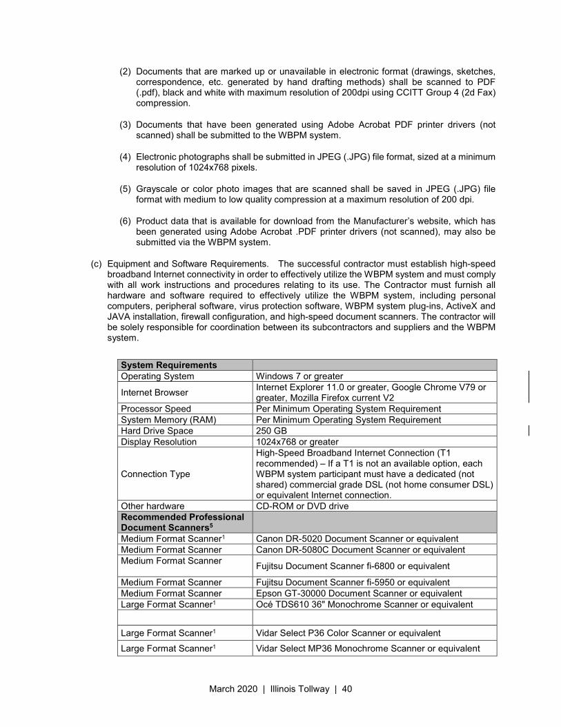
March 2020 | Illinois Tollway | 40
(2) Documents that are marked up or unavailable in electronic format (drawings, sketches, correspondence, etc. generated by hand drafting methods) shall be scanned to PDF (.pdf), black and white with maximum resolution of 200dpi using CCITT Group 4 (2d Fax) compression.
(3) Documents that have been generated using Adobe Acrobat PDF printer drivers (not scanned) shall be submitted to the WBPM system.
(4) Electronic photographs shall be submitted in JPEG (.JPG) file format, sized at a minimum resolution of 1024x768 pixels.
(5) Grayscale or color photo images that are scanned shall be saved in JPEG (.JPG) file format with medium to low quality compression at a maximum resolution of 200 dpi.
(6) Product data that is available for download from the Manufacturer’s website, which has been generated using Adobe Acrobat .PDF printer drivers (not scanned), may also be submitted via the WBPM system.
(c) Equipment and Software Requirements. The successful contractor must establish high-speed broadband Internet connectivity in order to effectively utilize the WBPM system and must comply with all work instructions and procedures relating to its use. The Contractor must furnish all hardware and software required to effectively utilize the WBPM system, including personal computers, peripheral software, virus protection software, WBPM system plug-ins, ActiveX and JAVA installation, firewall configuration, and high-speed document scanners. The contractor will be solely responsible for coordination between its subcontractors and suppliers and the WBPM system.
System Requirements Operating System Windows 7 or greater
Internet Browser Internet Explorer 11.0 or greater, Google Chrome V79 or greater, Mozilla Firefox current V2
Processor Speed Per Minimum Operating System Requirement System Memory (RAM) Per Minimum Operating System Requirement Hard Drive Space 250 GB Display Resolution 1024x768 or greater
Connection Type
High-Speed Broadband Internet Connection (T1 recommended) – If a T1 is not an available option, each WBPM system participant must have a dedicated (not shared) commercial grade DSL (not home consumer DSL) or equivalent Internet connection.
Other hardware CD-ROM or DVD drive Recommended Professional Document Scanners5
Medium Format Scanner1 Canon DR-5020 Document Scanner or equivalent Medium Format Scanner Canon DR-5080C Document Scanner or equivalent Medium Format Scanner
Fujitsu Document Scanner fi-6800 or equivalent
Medium Format Scanner Fujitsu Document Scanner fi-5950 or equivalent Medium Format Scanner Epson GT-30000 Document Scanner or equivalent Large Format Scanner1 Océ TDS610 36" Monochrome Scanner or equivalent
Large Format Scanner1 Vidar Select P36 Color Scanner or equivalent
Large Format Scanner1 Vidar Select MP36 Monochrome Scanner or equivalent

March 2020 | Illinois Tollway | 41
Required Additional Software
Portable Document Format(.PDF) file reader
Adobe Acrobat Reader2
Portable Document Format(.PDF) file generator
Adobe Acrobat3
ZIP File compression utility WinZip4 or equal
(1) Large format scanning may also be outsourced to a digital reproduction house in your locale.
(2) Adobe Acrobat Reader is free software available for download at http://www.adobe.com/
(3) Adobe Acrobat is not free software and must be purchased. At least one copy of the software must be purchased by the Contractor and must reside on a PC accessible to all users within the Contractor’s project office. The purchase and installation of multiple copies is recommended.
(4) A fully functional evaluation version of WinZip is available for download at http://www.winzip.com/, alternative free file compression utility is 7-zip available at http://www.7-zip.org/
(5) The scanner models specified meet the requirements of website usage and are provided for information purposes only. Scanner models may change or be discontinued by the manufacturer.
(d) Measurement and Payment. There will be no separate measurement or payment for fulfilling the requirements described herein, and all cost, direct or indirect, shall be provided at no additional cost to the Illinois Tollway.
March 2020 | Illinois Tollway | 42
Illinois State Toll Highway Authority
SUPPLEMENTAL SPECIFICATION FOR
SECTION 106. CONTROL OF MATERIALS
Issued April 1, 2016 Revised March 23, 2020
This Supplemental Specification amends and supersedes the provisions of the Illinois Department of Transportation Standard Specifications for Road and Bridge Construction, adopted April 1, 2016 and shall be construed to be a part thereof, superseding any conflicting provisions thereof applicable to the work under the contract.
Delete Section 106 in its entirety and replace with the following.
106.01 Quality of Materials. In the event that the Contractor intends to substitute materials, products, or equipment of a trade name or manufacturer different from that specified in the Contract Documents, the Contractor must obtain the written approval of the Engineer to use such substitute materials, products, or equipment prior to placing any order therefore. The substitution request of the Contractor shall include quality and performance data and comparative information about the materials, products, or equipment required under the Contract Documents and those that the Contractor intends to substitute. Notwithstanding the approval by the Engineer, the Contractor shall be held responsible for any failure whatsoever in the quality or performance of such approved substitute materials, products, or equipment. The Contractor will also be solely responsible for any delays caused by the substitution of different materials, products or equipment or by any requests made therefore, whether granted or denied.
All materials to be permanently incorporated in the Work shall be new unless otherwise specifically prescribed in the contract documents.
The Contractor acknowledges and agrees that it will maintain its performance of the Contract and complete the construction of The Work by the Completion Date, notwithstanding the quality and performance or lack thereof of any specified or substituted materials, products, or equipment.
106.02 Unacceptable Materials. In the event the Engineer finds materials which are incorporated in The Work or the finished product in which the materials or products used are not in compliance with the Contract Documents, the Contractor shall promptly remove them and replace them with the specified materials or products, at no additional cost to the Illinois Tollway.
106.03 Sampling, Testing and Cited Specifications. In order to assure the use of suitable materials, the Illinois Tollway may require any or all materials to be subject to tests by means of samples or other suitable means. The Contractor shall cooperate with and afford such facilities as the Engineer may require for collecting and forwarding samples. The Contractor shall not make use of or incorporate in The Work any material represented by said samples until the tests have been made and the materials are found to be acceptable and in compliance with the requirements of the Specifications. The Contractor shall furnish all required samples without additional cost to the Illinois Tollway.
Within 24 hours after receiving a shipment of unsampled material, the Contractor shall advise the Engineer in writing of the kind, size, quantity, and location of such materials.
March 2020 | Illinois Tollway | 43
Unless otherwise provided, all materials shall be sampled and tested in accordance with the latest published AASHTO Standard Specifications for Transportation Materials and Methods of Sampling and Testing as revised to the date of Advertisement for Bids. In case there are no AASHTO standards which are applicable, Standard Methods of the American Society for Testing Materials as revised to the date of Advertisement for Bids shall be used. In case there are no ASTM standards which apply, applicable Standard Methods of the Federal Government, or of the American Concrete Institute, or other Standard Methods specified in the Contract, as revised to the date of Advertisement for Bids, shall be used. If no such Standard Methods apply or are specified in the Contract, sampling and testing shall be as approved by the Engineer.
For the verification of weights or proportions and character of materials and determinations of temperatures used in the preparation of the materials and mixtures, the Engineer shall have full and complete access at all times to all plants or factories mixing, furnishing, or fabricating materials to be used in The Work. The Contractor shall facilitate and assist in verification of the accuracy of all scales and other measuring devices used by it and any material suppliers.
The Contractor warrants and guarantees that all materials used in The Work will conform to the Specifications, and that all work will be performed in a proper, good and workmanlike manner and in accordance with the Contract.
106.04 Inspection of Materials. All materials shall be subject to inspection by the Engineer or the Illinois Tollway’s representative. The Contractor shall give sufficient advance notice of placing orders to permit inspections (which may include sampling and testing) to be completed before the materials are incorporated in The Work, and it shall cooperate with and make available such facilities as the Engineer may require for collecting and forwarding samples and making inspections. All samples shall be furnished at no additional cost to Illinois Tollway.
The Contractor shall not make use of or incorporate in The Work any materials to be inspected until inspections, including any necessary sampling and testing, have been completed and the materials found to be in accordance with the requirements of the Contract Documents.
The Illinois Tollway shall have the right to inspect the materials at their source or elsewhere, but it is understood that the Illinois Tollway is not obligated to inspect materials in any particular manner or location. Plant inspection, when made, will be at the expense of the Illinois Tollway, and the Contractor and the materials producer or supplier shall afford all such facilities and cooperation as may be required so that the Illinois Tollway or its representatives may satisfy themselves as to the quality, quantity, and identity of the materials involved. They shall supply promptly an appropriate number of copies of purchase orders, internal production orders, shipping bills, and other papers. The representatives of the Illinois Tollway shall have free, uninhibited and safe entry at all times to such parts of the plant as concern the manufacture and production of the materials ordered. When said representatives are in or about such premises in the course of their employment, they shall be deemed conclusively to be invitees of the Contractor. If the Contractor is not the owner of the place where fabrication, preparation, or manufacture is in progress, the owner thereof shall be deemed to be the agent of the Contractor with respect to the obligation assumed hereunder.
Inspection of material at a producer’s or supplier’s plant by the Illinois Tollway is conducted to assist in maintaining consistent progress and quality and may, in fact, preclude or reduce the loss of time and the expense which might otherwise result from the rejection of faulty material after its delivery to the site of The Work. Any such inspection shall not, however, be construed as final acceptance. Materials may also be inspected for compliance with the Specifications at the time and place they are incorporated in The Work, and the Illinois Tollway reserves the right to reject any materials which do not meet the requirements of the Specification at the time they are used, regardless of prior inspections.
The acceptance of materials on the basis of samples obtained and tests performed by or on behalf of the Illinois Tollway shall not relieve the Contractor of the obligation to provide materials which meet the requirements of the Contract.
March 2020 | Illinois Tollway | 44
When inspection is made at a producer’s plant, the Contractor shall cause the producer, when required by the Engineer, to furnish a weather-proof building or suitable space within a weather-proof building for the exclusive use of the Illinois Tollway’s inspector. The building or space shall be located conveniently to the site of fabrication. Unless otherwise approved by the Engineer, it shall conform to the following requirements:
Floor space, not less than ............................................... 120 sq. feet
Height of ceiling, not less than .................................................. 8 feet
Windows, not less than .................................................................... 3
Door, with lock approved by the Engineer ...................................... 1
Type of Floor ......................................................................... Wood
Instrument locker, 2'x3'x3', with Adjustable shelves .............................. 1
Hinged wall table, 2 ½ x 6' ............................................................... 1
The producer or supplier shall provide lights, utility outlets, water, heat and air conditioning for the building or space provided, and sanitary facilities. All keys to the building or space provided shall be turned over to the Engineer.
106.05 Source of Materials. The source of supply, of each material used, shall be approved by the Engineer before delivery is started. If sources previously approved are found to be unacceptable at any time and fail to produce materials satisfactory to the Illinois Tollway, the Contractor shall furnish materials from other approved sources.
If the Contractor decides to investigate new sources of supply, the Contractor shall furnish without charge such preliminary samples as the Illinois Tollway may require. Test will be made on these preliminary samples and reports rendered, but it is understood that such tests are for informational purposes only and tests shall not be considered as a guarantee of acceptance of any material which may be delivered later for incorporation in the Work. Only materials actually delivered for use will be considered, and their acceptance will be based solely upon the results of the test made on these materials.
If the Contractor installs equipment or apparatus to produce materials from new sources of supply, the Contractor does so at his/her own risk, and the Contractor shall assume full responsibility for the production of uniform and satisfactory materials. In case of failure of a source of supply to produce materials satisfactory to the Illinois Tollway, the Contractor shall indemnify and save harmless the Illinois Tollway from any and all claims for loss or damage of whatever nature which the Contractor may have suffered by reason of the installation of equipment and the operation of such sources of supply.
When materials are furnished to the Contractor by the Illinois Tollway for inclusion in the work, the Contractor’s responsibility for all such materials shall be the same as for materials furnished by the Contractor.
March 2020 | Illinois Tollway | 45
106.06 Stored Materials and Equipment. If it is necessary to store materials, they shall be protected in such manner as to insure the preservation of their quality and fitness for The Work. Materials shall be stored and located so as to facilitate prompt inspection. All stored materials shall be made available for inspection by the Engineer at the time of their use in The Work, even though they may have been inspected and approved before being placed in storage. All existing materials which are required to be removed and stored during the progress of The Work shall be carefully removed and stored at locations noted on the Plans, or as may be directed by the Engineer. When the Contractor is allowed to use the Toll Highway right-of-way for storage of materials, stockpiles shall be confined to such cleared areas as may be approved by the Engineer. If stockpiling is done or required to be done outside of the right-of-way, the additional space required shall be provided by the Contractor at no additional cost to the Illinois Tollway. The use of such storage sites shall be discontinued immediately upon completion of that portion of The Work for which the storage was required and the sites shall be cleaned of all surplus materials and debris and restored as nearly as possible to their original condition by the Contractor at no additional cost to the Illinois Tollway.
The Contractor may be permitted a storage yard for equipment or materials or a field office on Illinois Tollway property, with written permission from the Engineer, subject to the express conditions of such permission and provided the Illinois Tollway is indemnified and held harmless by the Contractor against all costs or liabilities in connection therewith. Under no circumstances will the Contractor’s employees be permitted to park personal vehicles on Toll Highway shoulders or in the median.
Storage of materials and equipment on Toll Highway pavement or shoulders, or adjacent thereto, shall be in strict conformance with the requirements set forth in Article 701.13.
106.07 Handling Materials. All materials shall be handled in such a manner as to preserve their quality and fitness for the work. Aggregates shall be transported from the storage sites to the work in tight vehicles so constructed as to prevent loss or segregation of materials after loading and measuring in order to prevent inconsistencies in the quantities of materials intended for incorporation in the work as loaded, and the quantities as actually received at the place of operations.
106.08 Certification of Metal Steel Fabricator. All fabricators performing work on metal components of structures shall be certified under the appropriate category of the AISC Certification Program for Steel Bridge Fabricators as follows:
(a) Fabricators of the main load carrying steel components of box girders, trusses over 200 feet in lengths, arches, cable supported, moveable, and curved (radii under 1000 feet) structures shall be certified under ABA: Certified Bridge Fabricator- Advanced (Major).
(b) Fabricators of the main load carrying steel components of spliced rolled beam, welded plate girders, either simple span or continuous, trusses under 200 feet in length, and curved (radii over 1000 feet) structures, shall be certified under IBR: Certified Bridge Fabricator- Intermediate (Major).
(c) Fabricators of main load carrying steel components of unspliced rolled beam sections shall be certified under SBR: Certified Bridge Fabricator- Simple.
(d) Fabricators of overhead sign structures shall be on IDOT’s List of pre-qualified Overhead Sign Structure Fabricators and certified under either (a), (b), (c) or Category Bridge and Highway Metal Component Manufacturers.
(e) Fabricators of steel or other non-ferrous metal components of structures, not certified under (a), (b), or (c) above, shall be certified under the AISC program for Bridge and Highway Metal Component Manufacturers.
In addition, fabricators of fracture critical main load carrying steel components of bridges shall also have the Fracture Critical Endorsement.
March 2020 | Illinois Tollway | 46
106.09 Electrical Work. Additional material requirements for electrical work shall be according to Articles 801.01 through 801.08 of the Standard Specifications.
March 2020 | Illinois Tollway | 47
Illinois State Toll Highway Authority
SUPPLEMENTAL SPECIFICATION FOR
SECTION 107. LEGAL RELATIONS AND RESPONSIBILITY TO THE PUBLIC
Issued April 1, 2016 Revised March 23, 2020
This Supplemental Specification amends and supersedes the provisions of the Illinois Department of Transportation Standard Specifications for Road and Bridge Construction, adopted April 1, 2016 and shall be construed to be a part thereof, superseding any conflicting provisions thereof applicable to the work under the contract.
Delete Section 107 in its entirety and replace with the following.
107.01 Laws to be Observed. The Contractor warrants that it is thoroughly familiar with and will comply with all Federal, State and local laws, statutes, ordinances, rules and regulations, and the orders and decrees of any courts or administrative bodies or tribunals which in any manner affect performance of the Contract; including, but not limited to, the Illinois State Toll Highway Authority Act, the Illinois Environmental Protection Act, the Worker’s Compensation Act, the Illinois Human Rights Act, minimum and prevailing wage statutes and regulations, the Citizens Preference Act, the Steel Products Procurement Act, any applicable occupational safety and health laws, laws with respect to permits, licenses and fees in connection therewith and laws regarding maximum working hours. No pleas of misunderstanding or ignorance thereof will be considered.
Whenever requested, the Contractor shall furnish the Engineer with satisfactory proof of compliance with applicable federal, state, and local laws, statutes, ordinances, rules, regulations, orders, and decrees.
(a) Wage Rates. The Contractor shall pay not less than the prevailing rate of wages as are on file with the Illinois Department of Labor, and are available at the following web site: http://www.state.il.us/agency/idol/. The Contractor shall be required to comply with the provisions of "an Act regulating the rates of laborers, mechanics, and other workers employed in any public works by the State, county, city or any public body of any political subdivision or anyone under contract for public works." (820 ILCS 130/0.01-12, as amended from time to time).
(b) Illinois Human Rights Act. The Contractor is advised that the Illinois Tollway has heretofore by resolution adopted all of the applicable requirements and provisions of the Illinois Fair Employment Practices Act, now the Illinois Human Rights Act (Ill. Rev. Stat., Ch. 68, Para. 1-101 et seq. as amended from time to time) and all of the applicable rules and regulations promulgated there under, and that all such applicable requirements, provisions and rules and regulations are deemed to be part of the Contract and to apply to the Contractor as if fully set out herein.
(c) Citizens Preference Act. The Contractor will be required to comply with the provisions of “An Act to give preference in the construction of public works projects and improvements to citizens of the United States who have resided in Illinois for one year.” (Ill. Rev. Stat., Ch. 48, Pars. 269-275 as amended from time to time)
March 2020 | Illinois Tollway | 48
(d) Steel Products Procurement Act. In accordance with the Steel Products Procurement Act (III. Rev. Stat., Ch. 48 Par 1801 as amended from time to time) steel products used or supplied in the performance of The Work shall be manufactured or produced in the United States. The Illinois Tollway requires certification of compliance with this Act.
(e) DBE Utilization Program. The Illinois Tollway has instituted a best efforts affirmative action program to encourage Contractors to increase the participation of disadvantaged business enterprises (DBE) on Illinois Tollway projects. The Illinois Tollway’s goals are set forth in the Proposal and the Special Provision for Disadvantage Business Enterprises Participation which is part of the Contract Documents. The Illinois Tollway encourages contractors to make a best effort to achieve the Illinois Tollway’s goals.
(f) Veteran Owned Small Business (VOSB) Program. A VOSB is a business certified by the State of Illinois Department of Central Management Services (CMS) as a Veteran-owned small business or Service-disabled Veteran-owned small business. The VOSB program is separate and distinct from the DBE program. A single firm may not participate in a single project as both a VOSB and DBE firm. The Illinois Tollway has created a Partnering for Growth Program and guidelines for Veteran Owned Small Businesses (VOSBs) and encourages firms providing professional services to review the Program requirements set forth in the Proposal and the Special Provision for Veterans Small Business Participation and Utilization Plan-Construction to assist the Illinois Tollway in achieving its goals.
107.02 Worker’s Compensation Insurance. Prior to the approval of his/her contract by the Illinois Tollway, the Contractor shall furnish to the Illinois Tollway certificates of insurance covering Worker’s Compensation, or satisfactory evidence that this liability is otherwise take care of according to Section 4(a) of the “Worker’s Compensation Act of the State of Illinois” as amended.
Such insurance, or other means of protection as herein provided, shall be kept in force until all work to be performed under the terms of the contract has been completed and accepted according to the specifications, and it is hereby understood and agreed the maintenance of such insurance or other protection, until acceptance of the work by the Illinois Tollway, is a part of the contract. Failure to maintain such insurance, cancellation by the Industrial Commission of its approval of such other means of protection as might have been elected, or any other act which results in lack of protection under the said “Worker’s Compensation Act” may be considered as a breach of the contract.
107.03 Reserved
107.04 Permits and Licenses. Except as provided in Article 107.13, the Contractor shall procure all permits and licenses, pay all charges and fees, and give all notices necessary and incident to the due and lawful prosecution of The Work, including such permits and licenses as may be required in connection with the transportation of materials or equipment over haul roads, streets, highways, or railroads. The Contractor shall verify the status of right-of-way parcels to be acquired.
107.05 Patented Devices, Materials and Processes. If any design, device, material or process covered by patent, trademark, or copyright is used in The Work, the Contractor shall provide for such use by suitable agreement with the patentee or owner and shall indemnify and save harmless the Illinois Tollway from and against all claims for infringement, and the costs thereof shall be included in the unit prices for the various pay items of the Contract. The Contractor shall, upon demand of the Illinois Tollway, furnish the Illinois Tollway with a copy of such agreement with the patentee or owner, and if such copy is not furnished when demanded, then the Illinois Tollway may, if it so elects, withhold any and all payments to the Contractor until such agreement is furnished. The Contractor and Surety shall indemnify and save harmless the Illinois Tollway from any and all claims for infringement by reason of the use of any such patented design, device, material, or process, or any trademark or copyright in connection with The Work to be performed under the Contract, and shall indemnify the Illinois Tollway for any costs, expenses, fees and damages which it may be obliged to pay by reason of any such infringement at any time during the prosecution of or after completion of The Work.
March 2020 | Illinois Tollway | 49
107.06 Surface Openings in Existing Roads. The Contractor shall arrange with Federal, State or local agencies for making openings for access to and from public roads and shall procure all permits and licenses, pay all charges and fees, and give all notices necessary therefore and incident thereto.
The Contractor shall notify the Engineer in writing prior to beginning any portion of The Work requiring such access opening that all such arrangements have been made.
107.07 Reserved
107.08 Sanitary Provisions. The Contractor shall observe all rules and regulations of any State or local health department, and shall not create or allow unsanitary conditions.
107.09 Public Convenience and Safety. The Contractor shall notify the Engineer at least ten Business Days in advance of starting any construction work which might in any way affect or inconvenience traffic or the public.
The Contractor shall conduct its operations so as to provide safe passage of traffic in The Work area and cause the least possible obstruction and inconvenience to the public. No greater length or amount of work shall be under construction at any time than the Contractor can prosecute properly with due regard to the rights and safety of the public.
Unless otherwise provided in the Special Provisions, all public traffic shall be permitted to pass through The Work with a minimum of inconvenience and delay.
When work is performed on structures over pedestrians or any type of traffic, the Contractor shall protect the pedestrians and/or traffic from falling objects and materials.
Spillage resulting from hauling operations along or across any public traveled way shall be removed immediately by the Contractor at its expense.
The Contractor shall conduct its operations so as not to interfere with existing traffic signal and highway lighting systems during the prosecution of The Work and the appropriate agency shall be permitted to perform routine maintenance.
Convenient access to driveways, houses, and buildings along the line of The Work shall be maintained at all times and temporary approaches to crossings or intersecting highways shall be provided and maintained during prosecution of The Work. When an abutting property owner’s access across the right-of-way line is to be replaced by other access facilities, the existing access shall not be closed until suitable replacement access is constructed and usable.
Water or other dust palliative for the alleviation or prevention of a dust nuisance shall be applied as directed by the Engineer.
The Contractor’s personnel and equipment shall only be permitted to enter and leave the Toll Highway or other highways via existing ramps, and shall be required to move in the direction of public traffic. All movements on or across the publicly traveled right-of-way shall be controlled by the Contractor so as not to endanger public traffic.
Any cost and expense incurred by the Contractor in conforming to the requirements of this Article shall be considered as included in the prices paid for the various Contract items of work and no additional compensation will be allowed therefore.
107.10 Reserved
March 2020 | Illinois Tollway | 50
107.11 Reserved
107.12 Work Involving Railroads. All work adjacent to or within any railroad right-of-way, whether or not it involves the construction of any grade separation structure, shall be subject to advance approval of the applicable railroad company and to inspection at all times by its properly designated representative(s). All such work shall be performed at such times and in such manner as not to unnecessarily interfere with the movement of trains or traffic upon the tracks of such railway company. The Contractor shall use all care and caution in order to avoid accidents, damage, and unnecessary delay and interference with the railroad company’s operations and property. The Contractor shall conduct operations upon the railroad right-of-way in full compliance with the rules, regulations, and requirements of such railroad. The Contractor shall have acquainted itself with such rules, regulations and requirements prior to the submission of its Bid Proposal. The costs of complying with the rules, regulations and requirements of such railroad shall be paid by the Contractor and shall be considered as included in the prices for the various pay items of the Contract and no extra compensation will be allowed therefore. The Contractor will be required to carry such railroad protective insurance as may be required by the Special Provisions and by the railroad.
Any flagging protection or inspector service required by the railroad for the safety of railway operations because of work being performed by the Contractor or in connection therewith, will be provided by the railroad and the cost thereof shall be reimbursed to the railroad by the Illinois Tollway on the basis of the railroad’s bills under a Contract Allowance item in the contract. The Contractor need not include the costs of such protection in his contract price.
In order that the railroad may be prepared to furnish protective services, the Contractor shall notify the railroad the minimum time designated by the railroad in advance of when the protective services are required. The Contractor shall make every effort to notify the railroad sufficiently in advance if previously requested flagger or inspection services will not be needed for any reason. Any costs for flagging protection or inspector service provided by the railroad at the Contractor’s request for those days when the Contractor does not work shall be borne by the Contractor.
Should the Contractor require a temporary crossing over the tracks of any railroad for its own convenience, the Contractor shall make its own arrangements with that railroad for the construction or use of any such crossing. Any costs associated with construction or removal of such temporary crossing shall be assumed by the Contractor.
The safety and continuity of operations of railroad traffic shall be of primary importance and shall at all times be protected and safeguarded.
Upon request, the Illinois Tollway will make available to the Contractor at the Illinois Tollway’s offices its records showing any agreements between the railroad and the Illinois Tollway which affect The Work, and the Contractor shall acquaint itself with and comply with all terms and provisions contained therein which are applicable and, to the extent there is any conflict, the terms of such agreement shall control over the other provisions contained herein.
Before commencement of any work within the railroad right of way, the Contractor shall give written notice to the Railroad Engineer at the address to be furnished by the Engineer. Such notice shall be in compliance with any agreement between the railroad and the Illinois Tollway. Whenever such work, in the opinion of the Railroad Engineer or his duly authorized representative, may affect the safety of railroad operations or personnel, the method of doing such work shall be submitted to the Railroad Engineer for written approval and no such work shall be commenced or prosecuted without such written approval. The approval of the Railroad Engineer shall not be considered as a release of the Contractor from responsibility or liability for any damage which the railroad may suffer, or for which it may be held liable by the acts of the Contractor or its subcontractors or their employees or agents.
March 2020 | Illinois Tollway | 51
When, in the opinion of the Railroad Engineer, the construction work causes a hazard to the safe operation of trains, the railroad company may place at the site of The Work, trainmen, flaggers, trackmen, watchmen or other employees deemed necessary by the Railroad to protect its interests; however, the providing of such employees and other precautions shall not relieve the Contractor or its subcontractors of any liability for injury or damages arising in connection with their operations. When The Work involves construction of or improvement to a structure separating the grades of the Toll Highway and a railroad, the requirements of this Article may be augmented by Special Provision setting forth detailed requirements applicable to the particular project and the particular railroad company’s rules, regulations, policies and operations.
107.13 Work at Navigable and Regulated Waters and other Streams. All work at navigable and regulated waters shall be conducted so that free navigation of the waterways will not be interfered with and so that the existing navigable depths will not be impaired. Work at all other streams shall be conducted so as to keep the streams clear and unrestricted.
The Illinois Tollway will obtain, at no cost to the Contractor, any necessary permits from governmental agencies for construction over, under, or adjacent to streams, bodies of water, or navigable and regulated waterways and for construction of channel changes. The Contractor shall ascertain that the permits have been obtained prior to commencement of work subject to this provision. The Contractor shall perform The Work in this Contract in accordance with the permits.
The Contractor shall not be entitled to additional compensation because of any delay on the part of the Illinois Tollway in obtaining the required permits, it being agreed and understood that the Illinois Tollway shall only be required to exercise reasonable efforts to obtain the necessary permits.
Any additional permits, licenses, or easements for rights of entry or access required to facilitate the Contractor’s operations shall be obtained by the Contractor at its expense. The Contractor shall schedule or reschedule its work so as to avoid delays caused by failure to obtain applicable permits.
107.14 Maintenance of Traffic. When work zone traffic control is required along the route under construction, or when any section of road is closed for construction operations of any type, or when any section of road is opened for traffic prior to completion of all work, the Contractor shall protect the workers and provide for safe and convenient public travel by providing adequate traffic control. The traffic control shall conform to the Traffic Control Plan, included in the contract, and to the requirements of Section 701.
107.15 Dirt on Pavement or Structures. Where the Contractor’s equipment is operated on any portion of the pavement or structures used by traffic on or adjacent to the section under construction, the Contractor shall clean the pavement of all dirt and debris at the end of each day’s operations, and at other times as directed by the Engineer.
The cost of this work shall be included in the unit prices bid and no additional compensation will be allowed.
107.16 Equipment on Pavement or Structures. The Contractor shall be responsible for all damage to public roads caused by the Contractor and its agents and sub-contractors. Public road pavement and structures shall be protected from damage caused by lugs or cleats on tracks or wheels of equipment by the use of plank ways, wooden track blocks, smooth tires, or as otherwise approved by the Engineer.
All equipment used in the prosecution of The Work shall comply with the legal load limits established by any applicable law, statute, ordinance or regulations, when moved over or operated on any pavement, structure or public road, unless prior permission in writing has been obtained by the Contractor from the proper authorities. Before using any equipment which may exceed the legal load limits, the Contractor shall secure a permit therefore in advance, allowing ample time to make a safety analysis for the proposed load. It is agreed and understood that the Illinois Tollway shall not be responsible for any delay in construction operations or for any costs incurred by the Contractor in complying with legal load limits, or for obtaining
March 2020 | Illinois Tollway | 52
variances, if any, from legal load limits.
107.17 Reserved
107.18 Use of Fire Hydrant. If the Contractor desires to use water from fire hydrants, it shall obtain prior written permission from the proper authorities, and shall conform to the municipal ordinances, rules or regulations concerning their use. Fire hydrants shall remain accessible at all times.
107.19 Removal and Disposal of Waste Materials. The Contractor shall be solely and entirely responsible for compliance with all Federal, State, and local laws, ordinances, regulations and directives with respect to the disposal of waste materials. In connection therewith the Contractor shall be solely and entirely responsible for obtaining all necessary permits, licenses or other authorizations so as not to delay The Work and shall be responsible for the payment of all required fees and costs therefore, all without additional cost to the Illinois Tollway, except as modified in Article 107.19(a).
Burning of waste materials within the limits of the Toll Highway right-of-way or in close proximity thereto will not be permitted under any circumstances.
(a) Hazardous Waste Material. Should any substance at any time be encountered which may be classified as a waste and subject to the requirements of the Resource Conservation and Recovery Act (Hazardous Waste), the Toxic Substances Control Act (PCB), Clean Air Act (Asbestos), or State Regulations (Special Wastes), the Contractor shall be solely and entirely responsible for notifying the Engineer, the Chief Engineering Officer and the appropriate authorities with jurisdiction over such materials.
The Contractor shall control access to the site and shall take immediate steps to prevent the waste from migrating off site. The Contractor shall fully cooperate with such authorities and the Engineer. All required permitting, removal, disposal, and any incidentals necessary to complete this work as required by the applicable statutes and authorities will be considered Alterations, Cancellations and Deductions as defined in Article 104.02. Final payment will be made upon satisfactory evidence of compliance with all applicable Statutes, etc. Payment will be made in accordance with Article 109.04.
107.20 Protection and Restoration of Property. The Contractor shall not enter upon private property for any purpose in connection with The Work without obtaining prior permission from the owner. If necessary, the Contractor shall obtain any required environmental permit before utilizing the property and shall comply with the requirements of all applicable Federal, State, local laws, and environmental laws and regulations through the use of the property. The Contractor shall furnish the Engineer with copies of any agreements between the Contractor and the owner along with copies of any environmental permits concerning the use of the property. The Contractor shall take all necessary precautions for the protection of public or private property, such as vaults, underground structures of public utilities, underground drainage facilities, overhead structures of public utilities, trees and shrubbery.
The Contractor shall familiarize itself with the location of all public utility and Illinois Tollway services, facilities, and structures that may be found in the vicinity of the construction. The Contractor shall conduct its operations to avoid damages to the utilities or structures belonging to the Illinois Tollway and any other owners. The Contractor is responsible for meeting all the requirements established by the Illinois Tollway and such other owners for the protection and restoration of their property and facilities.
When or where there occurs any direct or indirect damage or injury to public or private property, by or on account of any act, omission, neglect, or misconduct in the execution of The Work, or in consequence of the execution or non-execution thereof on the part of the Contractor, such property shall be restored by the Contractor and at the Contractor’s expense to a condition equal to that existing before such damage or injury, in a manner or amount acceptable to the Illinois Tollway and to the owner or owners of such property. In the event the Contractor fails to restore or compensate for such property damage or injury, the Illinois
March 2020 | Illinois Tollway | 53
Tollway may, upon 48 hours’ notice, compensate the owner or owners, or proceed to repair, rebuild or otherwise restore such property in amounts or in a manner as may in the sole judgment of the Illinois Tollway be deemed necessary, and the cost thereof shall be deducted from any monies due or which may become due the Contractor under this Contract.
(a) Preservation of Survey Monuments. The Contractor shall cooperate with the Illinois Tollway in protecting and preserving all cornerstones and survey monuments that are within the right-of-way of the Toll Highway or any public road. The Contractor shall not start operations until the Engineer has referenced all known cornerstones, monuments, and land markers in The Work area. Monuments, cornerstones, and land markers unexpectedly encountered shall be protected and preserved until legally referenced by the Engineer. When cornerstones, monuments and land markers are encountered in the performance of The Work, the Contractor shall immediately notify the Engineer and if monument covers are not listed in the proposal, the Contractor shall furnish them. The Engineer will supervise their precise location and installation, and the Contractor will furnish all the labor, tools and other materials requested or incidental to such installations. Any monument covers, labor, tools and materials so furnished shall be paid for in accordance with the provisions of Article 109.04. The Contractor is responsible for the preservation of cornerstones and survey markers. The cost to the Illinois Tollway for repair, relocation, and replacement of any cornerstone, monument, or land marker which is damaged, destroyed, or made inaccessible by the Contractor shall be charged to the Contractor and may be deducted from any monies due or which may become due to the Contractor under the Contract.
107.21 Protection and Preservation of Aboriginal Records and Antiquities. The Contractor shall take reasonable precaution to avoid disturbing aboriginal records and antiquities of archaeological, paleontological, or historical significance. No objects of this nature shall be disturbed without written permission of the Engineer. When such objects are uncovered unexpectedly, the Contractor shall immediately notify the Engineer of their presence and shall not disturb them until written permission to do so is granted.
If it is determined by the Chief Engineering Officer that exploration or excavation of aboriginal records or antiquities on land owned or leased by the Illinois Tollway is necessary to avoid loss, the Contractor shall cooperate in the salvage and preservation work. If the Chief Engineering Officer determines that the salvage work will materially delay the Contractor’s work, an appropriate extension of Contract time will be granted therefore, but the Contractor shall not be entitled to additional compensation or damages due to such delay. If the Engineer determines that the salvage work to be performed by the Contractor is of a nature or scope not covered by the Contract, such work shall be considered as Extra Work as defined in Article 104.02 and payment therefore shall be as specified in Article 109.04.
107.22 Proposed Borrow Areas, Use Areas, and/or Waste Areas. Proposed borrow areas, use areas, (including, but not limited to temporary access roads, detours, and runarounds, plant sites and staging and storage areas), and/or waste areas are to be designated by the Contractor to the Engineer and approved prior to their use. The Contractor shall ensure and provide documentation that each site will not impact any archaeological resources, wetlands, or threatened and endangered species in accordance with Illinois Tollway policies, and in compliance with State, Federal and local regulations. A location map delineating the proposed borrow site, use area, and/or waste area shall be submitted to the Engineer for approval along with a written agreement from the property owner.
107.23 Temporary Water Pollution Control (Soil Erosion) and Natural Resource Protection.
The Contractor shall be responsible for any pollution or erosion damage caused by its activities.
The Contractor shall provide and maintain erosion control measures as required by the Plans and Specifications, and comply with the requirements of all applicable Federal, State, and local laws, rules and regulations, and directions of the Engineer to control water pollution through use of beams, dikes, dams, sediment basins, fiber mats, netting, gravel, mulches, grasses, slope drains, and other erosion control
March 2020 | Illinois Tollway | 54
devices or methods and the site actives of a project will be conducted under the Illinois Environmental Protection Agency (IEPA) General Permit to Discharge Stormwater associated with construction site activities (ILR10). Any temporary pollution control provisions required by the Engineer shall be coordinated with the permanent erosion control features specified elsewhere in the Contract to the extent practical to assure economical, effective and continuous erosion control throughout the construction and post construction period. The contractor shall prepare a detailed Erosion and Sediment Control Plan (ESCP) and a Stormwater Pollution Prevention Plan (SWPPP) that addresses erosion and sediment control issues, stormwater management, and control of other construction-related pollutants that could impact the environment. Included are the installation of the required measures by the Contractor, along with the implementation of an active inspection and maintenance program, and the filing of the necessary required documents.
At the pre-construction meeting or prior to the start of the applicable construction, the Contractor shall discuss and submit to the Engineer for acceptance its schedules and procedures for erosion control in connection with clearing and grubbing, grading, and bridge and other structure construction at watercourses, including miscellaneous construction and paving as detailed in their ASCP and SWPPP. The Contractor shall also submit to the Engineer for acceptance its proposed method of erosion control on haul roads and in borrow pits and its plan for disposal of waste materials. No such work shall be started or use made of haul roads or borrow pits until the erosion control schedules and methods have been approved by the Engineer.
If there is a conflict between the requirements of the Specifications and any applicable pollution control laws, rules or regulations, the more restrictive of the laws, rules, regulations or specifications shall apply. The Contractor shall take sufficient precautions to prevent pollution of streams, lakes and reservoirs with fuels, oils, bitumens, chlorides, alkalis, or other harmful materials.
If temporary erosion and pollution control measures are required due to Contractor’s negligence, carelessness, or failure to install permanent controls as a part of The Work as scheduled, and are ordered to be taken by the Engineer, such work shall be performed by the Contractor at no additional cost to the Illinois Tollway. Temporary erosion and pollution control work required, which is not attributed to the Contractor’s negligence, carelessness or failure to install permanent controls, shall be performed as directed by the Engineer. Where such work is not attributable to the Contractor’s violation of the Contract or to the Contractor’s negligence, carelessness or failure to install permanent controls and there is a Contract unit price therefore, The Work shall be paid for at the Contract unit price. Should there not be a Contract unit price for such work, the Contractor shall perform such work as Extra Work in accordance with Article 104.02, and payment therefore shall be as specified in Article 109.04.
In case of repeated failures on the part of the Contractor to control erosion, pollution, and/or siltation, the Illinois Tollway reserves the right to employ outside assistance or to use its own forces to perform the necessary corrective work. In such event, all costs and expenses associated with said work, including engineering costs, will be charged to the Contractor, and may be deducted from any payments due or to become due the Contractor. The Contractor shall also pay any fines that may be provided in the Special Provisions for such failures.
Required pollution control measures may include work outside the right-of-way where such work is necessary as a result of roadway construction, including but not limited to, borrow pit operations, haul roads and equipment storage sites.
The Contractor shall not disturb designated natural areas, wetlands, identified locations where State
or Federal-listed endangered or threatened species are known to occur, or areas that have been designated as essential habitat for such species, or prairie or Savannah areas where the Illinois Tollway has made commitments for protection of these locations/areas. Also, if previously unidentified natural areas, wetlands, prairies, savannahs, or areas or locations suspected of containing protected species are identified during construction, the Contractor shall not disturb them unless written permission to do so is granted by the Engineer.
March 2020 | Illinois Tollway | 55
107.24 Forest Protection. In performing The Work within or adjacent to forest preserves or other public woodlands, the Contractor shall comply with all regulations of the State Fire Marshal or other authority having jurisdiction over said preserves and woodlands, and the Contractor shall observe all sanitary laws and regulations with respect to the performance of work in such areas.
The Contractor shall take all reasonable precautions to prevent and suppress forest fires and shall require its employees and subcontractors, both independently and at the request of officials of such preserves and woodlands, to do all within their power to prevent and suppress and to assist in preventing and suppressing forest fires. The Contractor, its subcontractors, employees and agents shall immediately notify such officials of the location and extent of any fire seen by them.
107.25 Reserved
107.26 Indemnification. To the fullest extent permitted by law, the Contractor shall indemnify and save harmless the Illinois Tollway, its directors, officers, employees, agents and its Consulting Engineer, and the State of Illinois from any and all claims, suits, actions, costs and fees of every nature or description, arising from, growing out of, or connected with The Work to be performed under this Contract, or on account of or in consequence of any act or omission in safeguarding The Work, or on account of or in consequence of using unacceptable materials in performing The Work, or because of any act or omission, neglect or misconduct of the Contractor, its employees and agents, or its subcontractor(s), or because of any claims or amount recovered by reason of their infringement of any patent, trade mark or copyright or by reason of their violation of any law, ordinance, order or decree, and such indemnity shall not be limited by reason of the enumeration of any insurance coverage herein provided. Nothing herein contained shall be construed as prohibiting the Illinois Tollway, its directors, officers, agents, employees, or it’s Consulting Engineer, from defending through the selection and use of their own agents, attorneys and experts, any claims, actions or suits brought against them. The Contractor shall likewise be liable for the costs, fees and expenses incurred in the defense of any such claims, actions, or suits by the Illinois Tollway and its directors, officers, employees and agents, and/or the Contractor.
107.27 Insurance. The Contractor shall obtain and thereafter keep in force for the term of the Contract including all options and extensions the following insurance. Whether stated in this Article or elsewhere, the Illinois Tollway does not warrant the adequacy of the types of insurance coverage or the limits of liability specified. Failure to request certificates of insurance, policy endorsements or insurance policies, either initially or at any policy renewal, does not constitute a waiver by the Illinois Tollway of the Contractor’s obligations and requirements to maintain the minimum coverage specified.
(a) General Provisions. Insurance coverage shall be provided by insurance companies acceptable to the Illinois Tollway and authorized to transact business under the laws of the State of Illinois. The insurance companies providing coverage shall be rated by A.M. Best Company with a Financial Strength Rating of A- or better and a financial size category of not less than VII.
The Contractor shall procure and maintain insurance against claims for bodily injury or property damage, which may arise from or in connection with the performance of the work under Contract by the Contractor, the Contractor’s agents, representatives, employees and subcontractors. The Contractor shall not commence work until all the insurance required by this section or any contract Special Provision has been obtained, and proper insurance documentation has been submitted and accepted by the Illinois Tollway.
Insurance documentation, including copies of applicable additional insured endorsements shall be filed with the Illinois Tollway at or before the time of executing the Contract. Contractor shall provide a copy of the Builders Risk insurance policy within sixty (60) days of the date of Notice to Proceed. Upon Illinois Tollway request, the Contractor shall promptly provide copies of current insurance policies, forms, and endorsements, properly certified as accurate copies. Within three (3) business days after any renewal or replacement of coverage, the Contractor shall submit to the Illinois Tollway insurance documentation evidencing the limits and coverages as required herein. The obligations under this section are mandatory.
March 2020 | Illinois Tollway | 56
(b) Deductibles and Self-Insured Retention. The Contractor shall be solely responsible for any deductible or self-insured retention for any insurance policy provided by the Contractor. Any self-insured retention must be declared. Self-insured retentions in excess of $50,000 must be accepted by the Illinois Tollway.
(c) Policy Requirements. Policies, Certificates of Insurance, and other insurance documentation submitted by the Contractor will be on forms acceptable to the Illinois Tollway. Unless the Illinois Tollway consents in writing, all insurance procured by the Contractor pursuant to these requirements shall be written on an occurrence basis. Insurance shall not be cancelled or materially reduced unless a 30-day prior written notice is given by the Contractor to the Illinois Tollway, except as otherwise provided by State statute or insurance policy terms.
(d) Subcontractors. The Contractor shall have subcontractor(s) provide commercial general liability, business automobile liability, workers’ compensation and employer’s liability insurance and excess liability insurance with coverage as broad as is described under “Scope of Insurance” in Articles 107.27(e)(1) through (5) below. The limits of coverage will be determined by the Contractor. Unless otherwise required by a third party, the Contractor shall determine if subcontractor(s) must also provide contractor’s pollution liability insurance as described under “Scope of Insurance” in Article 107.27(e)(6) below. If the third-party requirement is not known at the time of the bid, then a contract adjustment will be considered in accordance with Article 109.04(b). The Contractor shall maintain, in Contractor’s files, evidence of all subcontractor insurance coverage. Failure to maintain evidence of subcontractor insurance shall not constitute a contractual breach.
(e) Scope of Insurance. Coverage shall be at least as broad as:
(1) Commercial General Liability – Including coverage for premises and operations, products and completed operations, independent contractor’s liability and unendorsed contractual liability. Policy coverage shall be on ISO occurrence form CG 00 01 (or an alternative form providing equivalent protection).
(2) Business Automobile Liability – Covering any vehicles, including owned, hired or non-owned vehicles, and including uninsured and underinsured motorist insurance coverage. Policy coverage shall be on the latest filed ISO occurrence form (or an alternative form providing equivalent protection).
(3) Workers’ Compensation as required by the State of Illinois and including Employer’s Liability. Coverage will be at least as broad as the Workers Compensation and Employers Liability Policy, National Council on Compensation Insurance Form #WC 00 00 00 A (ed. 4-92). Contractor may use a self-insured plan if the plan is approved by the Illinois Worker’s Compensation Commission.
If applicable, coverage shall include U.S. Longshore and Harbor Workers’ Compensation Act (LHWCA), Jones Act, or other Federal act exposures.
(4) Excess/Umbrella Liability – Providing excess coverage over the Contractor’s Commercial General Liability, Business Automobile Liability and Employers Liability Insurance. Coverage shall include drop-down provisions if the underlying coverage limit is reduced or exhausted.
(5) Builder’s Risk Insurance – Providing coverage, for the term of the contract, on an “all-risks” basis for physical loss or damage including, without duplication of coverage, theft, vandalism, and malicious mischief. This insurance shall name as Named Insureds the Illinois Tollway, the Contractor, and any sub-contractor of any tier to the extent of their insurable interest in the work and pre-existing structure(s).
March 2020 | Illinois Tollway | 57
(6) Contractor's Pollution Liability Insurance - covering third-party injury and property damage claims, including coverage for clean-up costs, defense costs, contractual liability, transportation, and owned and non-owned disposal sites, as a result of pollution conditions arising from the Contractor's operations and completed operations.
(f) Limits of Liability. Limits of liability will provide for the following provisions. Minimum limits requirement may be fulfilled with those indicated or the higher limits carried by the Contractor.
(1) Commercial General Liability - Limits of liability of not less than $1,000,000 each occurrence and $2,000,000 general aggregate, and $2,000,000 products-completed operations aggregate. The general aggregate limit shall be endorsed on a per project basis. Products completed operations coverage will be maintained by the Contractor for a minimum of two (2) years following acceptance of Work.
(2) Business Automobile Liability - Limit of liability of not less than $1,000,000 combined single limit for bodily injury and property damage each accident.
(3) Worker’s Compensation and Employer’s Liability
a. Workers’ Compensation – Statutory benefits.
b. Employer’s liability of $1,000,000 each accident, $1,000,000 disease each employee and $1,000,000 disease policy limit, including voluntary compensation.
(4) Excess/Umbrella Liability - In addition to the limits of coverage specified in (1), (2) and (3) above, not less than $25,000,000 each occurrence and aggregate per project will be maintained by the Contractor.
(5) Builder’s Risk Insurance – The policy limit shall be provided equal to the original contract award amount and shall be adjusted as needed to include all change orders and extra work orders.
(6) Contractor's Pollution Liability - limits of liability of not less than $2,000,000 each pollution condition and $2,000,000 general aggregate. This insurance shall be maintained for completed operations for a minimum of two (2) years following acceptance of Work.
(g) Certification of Coverage by Contractor Broker or Agent. The Agent/Broker for the Contractor must provide a certification letter on its letterhead attesting that:
(1) All provisions of the accepted certificates of insurance and policy binders have been obtained and
(2) All endorsements indicated have been secured from the insurance carrier.
This letter must clarify if the agency is a binding agent or a broker for the insurance carrier. Each certification letter must be signed by an officer of the brokerage or by a principal of the agency.
An updated letter must be provided with every submittal of insurance documentation for insurance policy renewals or changes.
(h) Cost of Insurance. The cost of all insurance required by these provisions shall be considered as included in the prices for the various pay items of the contract and no additional compensation will be allowed.
March 2020 | Illinois Tollway | 58
(i) Waiver of Subrogation. Policies shall contain a waiver of subrogation waiving any right of recovery that the insurance company may have against the Illinois Tollway, any Additional Insured, or any of the Illinois Tollway’s engineering firms and consultants.
(j) Additional Insured Protection. The Illinois State Toll Highway Authority together with its officials, directors and employees are to be named as “Additional Insured” with coverage as least as broad as set forth in ISO Form CG 2010 and CG 2037. This endorsed coverage shall be applicable to the primary commercial general liability insurance coverage of the Contractor for the project. Similar additional insured protection will be added to the business automobile liability and contractor's pollution liability insurance coverage.
As an alternative, if acceptable Commercial General Liability coverage as “Additional Insured” is not available, the Contractor shall obtain at its expense a separate Owners and Contractors Protective Liability insurance policy, with limits of not less than $4 million each occurrence and $ 4 million aggregate. The Illinois Tollway is to be the named insured on the policy. The insurance policy must meet the requirement of the Illinois Tollway.
The Consulting Engineer, the Program Management Office (PMO), Project Manager, Design Section Engineer, Design Corridor Manager, Construction Manager, and Construction Corridor Manager are to be named as Additional Insured with coverage at least as broad as set forth in ISO Form CG 2032 providing coverage for engineers, architects or surveyors. As part of the provisions and requirement for this project there may be a number of contracts, agreements and intergovernmental agreements related to the project that require the construction Contractor to include the contracting or agreement entity as an “additional insured” on the liability insurance of the Contractor. The Contractor shall assure these entities are included as covered parties as part of a blanket additional insured endorsement or individually named as additional insured.
The Special Provisions of the bidding documents may include entities that are to be included as “Additional Insured.”
The Contractor’s coverage shall be primary for the “Additional Insured” and not contributing with any other insurance or similar protection available to the “Additional insured” whether said other coverage be primary, contributing or excess.
107.28 Contractor Safety Responsibility. Nothing in this contract or the contracts between the Illinois Tollway and any construction engineering consultant(s) is intended or shall be construed, unless otherwise expressly stated, to reduce the responsibility of the Contractor, a subcontractor, anyone directly or indirectly employed by them or anyone for whose acts they may be liable, from full and complete supervision and achievement of workplace safety. Any inspection of work conducted by the Illinois Tollway, the construction engineering consultant(s), and the offices and employees of any of them, whether notice of the results thereof is provided to anyone or not provided to anyone, shall neither establish any duty on their parts nor create any expectation of a duty to anyone, including but not limited to third parties, regarding work place safety.
In order to ensure this and other duties of the Contractor certain indemnification and insurance is required by the contract. Additionally, the Contractor guarantees to the Illinois Tollway a safe work place shall be provided for all employees of the Contractor and each of its subcontractors. There shall be no violation by the Contractor, a subcontractor, anyone directly or indirectly employed by them, or anyone for whose acts they may be liable of the applicable standards of the Occupational Safety and Health Act, or any other work place safety act of this State. The Contractor agrees to require this work place safety guarantee of all subcontractors according to Article 108.01, and expressly to require the Illinois Tollway to be a third-party beneficiary of each guarantee.
107.29 Opening of Portion of the Work to Traffic. When a portion of The Work is completed,
March 2020 | Illinois Tollway | 59
the Illinois Tollway may approve the opening of that portion of The Work to traffic. This provision will be applicable only to that portion of The Work for which the Chief Engineering Officer has furnished to the Contractor a written approval for such opening. Responsibility shall remain with the Contractor for any damages within that approved portion of The Work which may be caused by defective work, or by failure to comply with the Contract.
In the event of such approval, the Contractor shall not be responsible for damages to the approved portion of the Work opened to traffic that is caused by negligence of parties other than the Contractor, its subcontractors or their agents or employees. The Contractor shall be responsible where the Contractor is required to furnish Builder’s Risk Insurance to cover these types of instances, as specified elsewhere in the Contract Documents. This approval may include safety-related hardware items such as impact attenuators, signs and related supports, roadway delineators, and guardrail and terminal sections. This approval shall not apply to facilities the Contractor is required to maintain throughout the duration of the Contract, and for which the Contractor is compensated for under a separate pay item, such as roadway lighting (including poles), and sediment or erosion control measures.
When damage occurs to portions of the Work by parties other than the Contractor, its subcontractors
or their agents and employees:
(1) The Illinois Tollway may correct and/or replace the damaged items with its own personnel; or
(2) The Illinois Tollway may direct the Contractor to correct and/or replace the damaged items. This work will be paid for as defined in Article 109.04.
Any approval granted under his Article shall neither constitute final acceptance of any of the Work nor be construed to be substantial completion thereof, and the work covered by any approval shall continue to be subject to final inspection and acceptance in accordance with the terms of the Contract. Repairs to work subject to the approval required due to defective materials or workmanship or caused in whole or in part by the Contractor’s operations or negligence, shall be performed at the Contractor’s expense including all traffic control measures necessary to undertake the repair work.
Such opening may also be directed by the Chief Engineering Officer when, a) the Contractor has not met its Progress Schedule, as extended by any extension of time granted by the Illinois Tollway, or b) in the opinion of the Engineer, the Contractor has made little or no progress under the Contract for a period of 14 Calendar Days or more. In such event, the Contractor shall continue to be responsible for any and all damages to the opened portion of The Work and any other completed or uncompleted work, and the Contractor will be required to complete the remaining work under traffic without extra compensation and at no additional cost to the Illinois Tollway for such maintenance of traffic or additional safety measures or revised work methods or equipment which may be made necessary thereby.
107.30 Contractor’s Responsibility for Work. All work included in the contract, including work added to the contract, shall be under the charge and care of the Contractor.
(a) General. Until final acceptance of The Work by the Illinois Tollway in accord with Article 109.08, or the approval and opening of a portion of The Work to traffic when completed in accordance with Article 107.29, the Contractor shall have the charge and care of and responsibility for The Work and shall take every necessary precaution against injury or damage to any part thereof by the action of the elements, from Contractor’s equipment, or from any other cause including the actions of third parties, whether arising during the execution or from non-execution of The Work. The Contractor shall rebuild, repair, restore, and make good all injuries or damages to any portion of The Work occurring before its completion and acceptance, and shall bear the expense thereof, except for damage by public traffic as provided below unless specified otherwise elsewhere. The Contractor shall not be relieved of its responsibility for The Work as set forth herein due to suspension of work. The Contractor shall be responsible for all devices, materials and equipment,
March 2020 | Illinois Tollway | 60
and shall properly store them, if necessary, and shall provide suitable drainage of the roadway and erect temporary structures, where necessary. The Contractor shall repair or replace at its own cost and as required, any Illinois Tollway-furnished devices, materials and equipment which may be broken, lost through fire, theft, or otherwise damaged, or in any way made useless for the purpose and use intended by the Plans and these Specifications subsequent to delivery to the Contractor by the Illinois Tollway and prior to final acceptance of The Work, no matter what the cause of such breakage, damage, loss, or uselessness, except for damage by public traffic as provided below unless specified otherwise elsewhere.
Damage by Public Traffic. Payment shall be made to the Contractor for repair or replacement of any permanent element of the highway which is completed to the stage of serving its intended function and is subsequently damaged by accident by public traffic. The Contractor must supply satisfactory evidence that such damage was caused by a public traffic accident and not by vandalism or by the Contractor’s equipment. Satisfactory evidence shall include, but not be limited to: accident reports filed with the Illinois Department of Motor Vehicles, State/local police; or identification of the vehicle involved in the accident; and supporting documents showing the contractor’s work activities and locations of equipment at the time of the accident. Physical evidence that the damage was caused by a motor vehicle (such as tire marks or broken headlight glass) will not be sufficient unless it can be shown that the damage was not caused by the Contractor’s vehicles or by vandalism.
This work will be paid for by means of force account in accordance with Article 104.02. Payment will not be made for repair or replacement in any way connected with untimely failure of any portion of the highway under public traffic, and the determination regarding this matter shall be made by the Engineer, taking into consideration the normal life and the amount of normal wear of the element involved. This provision does not relieve the Contractor of the responsibility of maintenance and protection of traffic for the contract or the responsibility of having wholly complete and acceptable work at the time of final inspection and contract acceptance. Payment for such damage repair shall be made only after the Contractor completes the repair work and all documentation for the repair and the accident has been supplied to the Engineer.
The Contractor shall cooperate with the Illinois Tollway in any recovery/collection efforts the Illinois Tollway initiates to obtain payment for the damages from the responsible motorist or their insurance carrier.
(b) Damage to Electrical, IT fiber, or ITS fiber Facilities. Should damage occur to any existing or new electrical, IT fiber, or ITS fiber facility through the Contractor’s operations, the Illinois Tollway reserves the right to determine whether the repairs are of an emergency or non-emergency nature. Repairs of a non-emergency nature shall be performed by the Contractor and approved by the Engineer. When the repair is of an emergency nature as determined by the Illinois Tollway, the Illinois Tollway shall have the option of directing the Contractor to immediately perform the repair work or the Illinois Tollway may authorize its own Electrical Maintenance Department to make emergency repairs and deduct the cost of such repair from the next pay estimate due the Contractor.
No extra compensation will be allowed the Contractor for compliance with these requirements or for any cost incurred by the Contractor for work performed by the Illinois Tollway’s Electrical Maintenance Department in making necessary repairs to damaged electrical facilities. All repairs performed by the Contractor shall be performed expeditiously and shall be subject to the supervision, inspection and approval of the Engineer. The Contractor shall conduct its work in such a manner that no lighting units will be out of service between the hours of 4:00 p.m. and 8:00 a.m. All lighting units shall be properly tested by 4:00 p.m. daily and any necessary repairs or corrections shall be made thereto immediately.
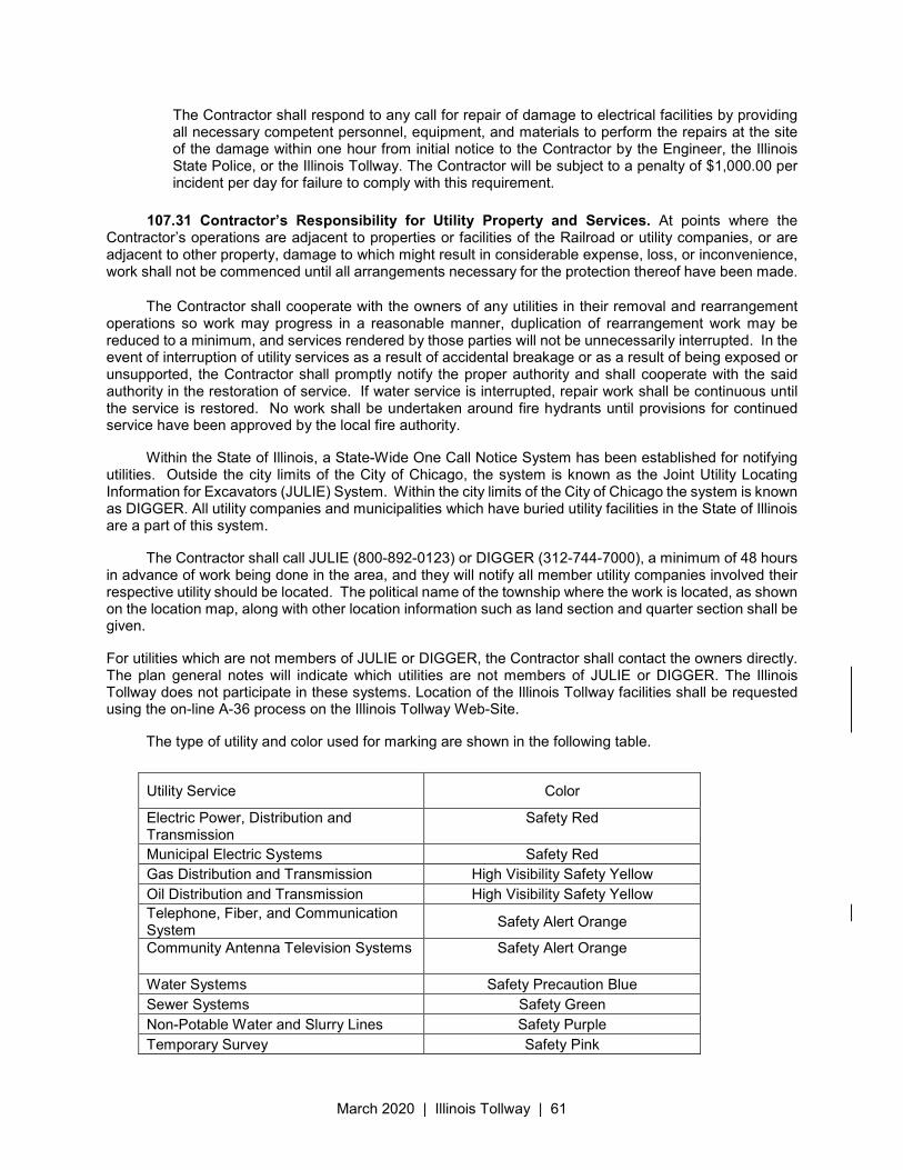
March 2020 | Illinois Tollway | 61
The Contractor shall respond to any call for repair of damage to electrical facilities by providing all necessary competent personnel, equipment, and materials to perform the repairs at the site of the damage within one hour from initial notice to the Contractor by the Engineer, the Illinois State Police, or the Illinois Tollway. The Contractor will be subject to a penalty of $1,000.00 per incident per day for failure to comply with this requirement.
107.31 Contractor’s Responsibility for Utility Property and Services. At points where the Contractor’s operations are adjacent to properties or facilities of the Railroad or utility companies, or are adjacent to other property, damage to which might result in considerable expense, loss, or inconvenience, work shall not be commenced until all arrangements necessary for the protection thereof have been made.
The Contractor shall cooperate with the owners of any utilities in their removal and rearrangement operations so work may progress in a reasonable manner, duplication of rearrangement work may be reduced to a minimum, and services rendered by those parties will not be unnecessarily interrupted. In the event of interruption of utility services as a result of accidental breakage or as a result of being exposed or unsupported, the Contractor shall promptly notify the proper authority and shall cooperate with the said authority in the restoration of service. If water service is interrupted, repair work shall be continuous until the service is restored. No work shall be undertaken around fire hydrants until provisions for continued service have been approved by the local fire authority.
Within the State of Illinois, a State-Wide One Call Notice System has been established for notifying utilities. Outside the city limits of the City of Chicago, the system is known as the Joint Utility Locating Information for Excavators (JULIE) System. Within the city limits of the City of Chicago the system is known as DIGGER. All utility companies and municipalities which have buried utility facilities in the State of Illinois are a part of this system.
The Contractor shall call JULIE (800-892-0123) or DIGGER (312-744-7000), a minimum of 48 hours in advance of work being done in the area, and they will notify all member utility companies involved their respective utility should be located. The political name of the township where the work is located, as shown on the location map, along with other location information such as land section and quarter section shall be given.
For utilities which are not members of JULIE or DIGGER, the Contractor shall contact the owners directly. The plan general notes will indicate which utilities are not members of JULIE or DIGGER. The Illinois Tollway does not participate in these systems. Location of the Illinois Tollway facilities shall be requested using the on-line A-36 process on the Illinois Tollway Web-Site.
The type of utility and color used for marking are shown in the following table.
Utility Service Color
Electric Power, Distribution and Transmission
Safety Red
Municipal Electric Systems Safety Red
Gas Distribution and Transmission High Visibility Safety Yellow
Oil Distribution and Transmission High Visibility Safety Yellow
Telephone, Fiber, and Communication System
Safety Alert Orange
Community Antenna Television Systems Safety Alert Orange
Water Systems Safety Precaution Blue
Sewer Systems Safety Green
Non-Potable Water and Slurry Lines Safety Purple
Temporary Survey Safety Pink
March 2020 | Illinois Tollway | 62
107.32 Furnishing Right-of-way. The Illinois Tollway will use its best efforts to acquire all necessary rights of way in advance of construction. In the event that all right-of-way is not acquired at the time that the Notice to Proceed is issued, the Contractor shall confirm its work schedule and order of performing The Work to maximize the amount of work which can be performed on the acquired right-of-way. Should the Contractor have insufficient work areas available to continue prosecution of The Work, as determined in the sole discretion of the Illinois Tollway, the Illinois Tollway may suspend The Work or portions thereof and grant an extension of time for any material delays in providing sufficient right-of-way. The Contractor shall not be entitled to damages or additional compensation due to failure of the Illinois Tollway to have sufficient right-of-way available to the Contractor at any given time.
Proposed right -of-way and easements for the performance of the Work may not be available at the time of bid opening or when Notice to Proceed is issued. The Contractor shall verify the status of right-of-way parcels to be acquired prior to the preparation of the Progress Schedule (Article 108.02 of these Supplemental Specifications). The Progress Schedule should reflect construction sequencing necessary to work only within acquired right-of-way parcels, and the Contractor shall take appropriate measures to ensure that construction operations do not encroach on parcels not acquired. The Contractor shall be required to adjust the order of his work from time to time to work within available right of way, and shall prepare revised Progress Schedule(s) in compliance therewith as directed by the Engineer.
Although portions of the right-of-way have already been acquired, the Illinois Tollway reserves the right not to issue the Notice to Proceed until sufficient right-of-way, as determined by the Engineer, is available for commencement of the Work. In any event, there shall be no damages or additional compensation due the Contractor for delays, if any, in issuing the Notice to Proceed or for delays due to a delay in furnishing the right -of-way, and the Contractor’s sole remedy, where applicable, shall be an extension of time.
107.33 Reserved
107.34 No Waiver of Legal Claims. The Illinois Tollway shall not be precluded or stopped by any measurement, estimate, or certificate made either before or after completion and acceptance of The Work or for payment therefore, from establishing the true amount and character of The Work performed and materials furnished by the Contractor, or from showing that The Work or materials do not conform in fact to the Contract or from recovering from the Contractor and Sureties such losses, fees, expenses and damages as it may sustain by reason of the Contractor’s failure to fully comply with any of the terms of the Contract. Neither the acceptance by the Illinois Tollway or any employee or representative of the Illinois Tollway of
Proposed Excavation Safety White (Black when snow is on the ground)
March 2020 | Illinois Tollway | 63
The Work or any portion thereof, nor any payment therefore nor the acceptance or approval thereof, nor the granting of any extension of time to the Contractor, nor the taking of any possession by the Illinois Tollway, shall operate as a waiver of any portion of the Contract, or of any power or right herein reserved, or any right to damages herein provided, or as a release of the Contractor and the Surety or Sureties. A waiver of any breach of the Contract shall not be held to be a waiver of any other subsequent breach.
107.35 Construction Noise Restrictions. All engines and engine driven equipment used for hauling or construction shall be equipped with an adequate muffler in constant operation and properly maintained to prevent excessive or unusual noise.
Construction within 1000 feet (300m) of an occupied residence, motel, hospital, or similar receptor shall be confined to the period beginning at 7 A.M. and ending at 10:00 P.M. This time regulation shall not apply to sawing contraction joints, as required in Article 420.05 of the Standard Specifications, maintenance or operation of safety and traffic control devices such as barricades, signs, and lighting, or to construction of an emergency nature.
Any machine or device or part thereof which is regulated by or becomes regulated by Federal of State of Illinois noise standards shall conform to those standards. Such equipment shall be operated as designated above.
Requests to modify or deviate from these requirements hall be submitted in writing by the Contractor and must be approved by the Engineer.
107.36 Construction Air Quality - Dust Control
(a) General. This work shall consist of developing and implementing a detailed Dust Control Plan (DCP). Development of a DCP is required. All construction activities shall be governed by the DCP. The nature and extent of dust generating activities, and specific control techniques appropriate to specific situations shall be discussed at the pre-construction meeting, with subsequent development of the DCP to include but not be limited to the requirements below.
The Contractor is responsible for the control of dust at all times during the duration of the contract, 24 hours per day, 7 days per week, including non-working hours, weekends, and holidays. This work shall be considered complete after the completion of all permanent erosion control measures required for the contract, and after all temporary and permanent seeding is established. Work on this contract shall be conducted in a manner that will not result in generating excessive airborne particulate matter (PM) or nuisance dust conditions as determined by the Engineer.
The DCP shall include legible copies of the product literature and Material Safety Data Sheets for dust suppression agents and stabilizers the contractor proposes to use. The Dust Control Plan shall describe the plan for the implementation of control measures before, during and after conducting any dust generating operation. These controls must be in place on non-working days and after working hours, not just while work is being done on the site. The Dust Control Plan must contain information specific to the project site, proposed work, and dust control measures to be implemented. A copy of the Dust Control Plan must be available on the project site at all times.
The Dust Control Plan must contain, at a minimum, all of the following information:
(1) Name, address and phone number of the person(s) responsible for the dust generating operation and for the submittal and implementation of the Dust Control Plan.
March 2020 | Illinois Tollway | 64
(2) A drawing specifying the site boundaries of the project with the areas to be disturbed, the locations of the nearest public roads, and all planned exit and entrance locations to the site from any paved public roadways.
(3) Control measures to be applied to all actual and potential fugitive dust sources before, during and after conducting any dust generating operation, including non-work hours and non-work days.
(4) A list of dust suppressants to be applied, including product specifications, Material Safety Data Sheets, and product label instructions that include the method, frequency and intensity of applications; and information on the environmental impacts and approval or certifications related to the appropriate and safe use for ground applications.
(5) A contingency plan consisting of at least one contingency measure for each activity occurring on the site in case the primary control measure proves inadequate.
The Contractor shall submit two copies of the DCP that outlines in detail the measures to be implemented by the Contractor complying with this section, including prevention, cleanup, and other measures at least 14 days before beginning any dust generating activity. The Contractor shall not begin any dust generating activities until the Construction Manager (Engineer) approves the DCP in writing.
(b) Materials.
(1) Water for Dust Control
a. Water shall meet the requirements of Section 1002 of the Standard
Specifications.
(2) Dust Suppression Agents
a. Dust suppression agents shall be water soluble, non-toxic, non-reactive, non-volatile, and non-foaming. Only plant-based or polyacrylamide-based products shall be used as a Dust Suppression agent; the use of petroleum or petroleum based suppression agents for dust control is strictly prohibited.
(3) Soil stabilizers shall consist of seed and mulch meeting the requirements of Article 1081.06 (a) (2) and (3).
(4) Covers for stockpiles shall be commercially available plastic tarps, or other materials approved by the Engineer.
(c) Construction Methods. Dust control watering and/or suppression agents shall be used to provide temporary control of dust on haul roads; construction staging, material storage, and laydown areas; or aggregate base roads and other active work areas. Several applications per day may be necessary to control dust depending upon meteorological conditions and work activity. The Contractor shall apply dust suppression on a routine basis as necessary or as directed by the Engineer to control dust. Wet suppression consists of the application of water or a dust suppression agent in solution with water. Water with a dust suppression agent shall not be applied directly to live plant material. Wet suppression equipment shall consist of sprinkler pipelines, tanks, tank trucks or other devices approved by the Engineer, capable of providing a regulated flow, uniform spray and positive shut off.
Haul truck cargo areas shall be securely covered during the transport of materials on public roadways that are prone to cause dust.
March 2020 | Illinois Tollway | 65
(d) Public Roadway Dust Control. Track-out, including carryout and spillage of material that adheres to the exterior surfaces of or are spilled from motor vehicles and/or equipment and subsequently fall onto a paved public roadway must be controlled at all times. Clean up of carryout and spillage is required immediately if it extends a cumulative distance of 50 feet or more on a paved public roadway. If the extent of carryout is less than 50 feet, clean up at the end of the day is permissible unless otherwise directed by the Engineer. Clean up of paved surfaces shall be by wet spray power vacuum street sweeper. Dry power sweeping is prohibited.
(e) Control of Earthwork Dust. During batch drop operations (i.e. earthwork with a front-end loader, clamshell bucket, or backhoe), the free drop height of excavated or aggregate material shall be reduced to minimum heights as necessary to perform the specified task, and to minimize the generation of dust. To prevent spills during transport, a minimum of 2 inches of freeboard space shall be maintained between the material load and the top of the truck cargo bed rail. A maximum drop height of two feet (or minimum height allowed by equipment) will be allowed, or to heights as directed by the Engineer.
(f) Control of Dust on Stockpiles and Inactive Work Areas. The Contractor shall use the following methods to control dust and wind erosion of stockpiles and inactive areas of disturbed soil:
(1) Water and/or a water and dust suppression agent mixture shall be used during active stockpile load-in, load-out, and maintenance activities.
(2) Soil stabilizers (hydraulic or chemical mulch) shall be applied to the surface of inactive stockpiles and other inactive areas of disturbed soil. Final grading and seeding of inactive areas shall occur immediately after construction activity is completed in an area and as directed by the Engineer.
(3) Plastic tarps may be used on small stockpiles, secured with sandbags or an equivalent method approved by the Engineer, to prevent the cover from being dislodged by the wind. The Contractor shall repair or replace the covers whenever damaged or dislodged at no additional cost.
(g) Method of Measurement. All measuring devices shall be furnished by the Contractor and approved by the Engineer.
This work will be measured in units of 1000 gallons of water or water with soluble dust suppression agent applied. The dust suppression agent shall be added to the water to form a solution in accordance with the manufacturer's recommendation.
All other dust control measures will not be measured for payment.
(h) Basis of Payment. The application of water for dust control work will be paid for at the contract unit price per unit for DUST CONTROL WATERING.
The application of the water and dust suppression agent mixture for dust control will be paid for at the contract unit price for APPLY DUST SUPPRESSION AGENTS.
All other dust control measures will not be paid for directly but shall be considered as included in the various items involved and no additional compensation will be allowed.
107.37 Construction Air Quality - Diesel Vehicle Emission Controls
(a) General. The reduction of construction air emissions shall be accomplished by using cleaner burning diesel fuel and/or by installing Retrofit Emission Control Devices. The term “equipment” refers to any and all diesel fuel powered devices rated at 50 hp and above, to be used on the
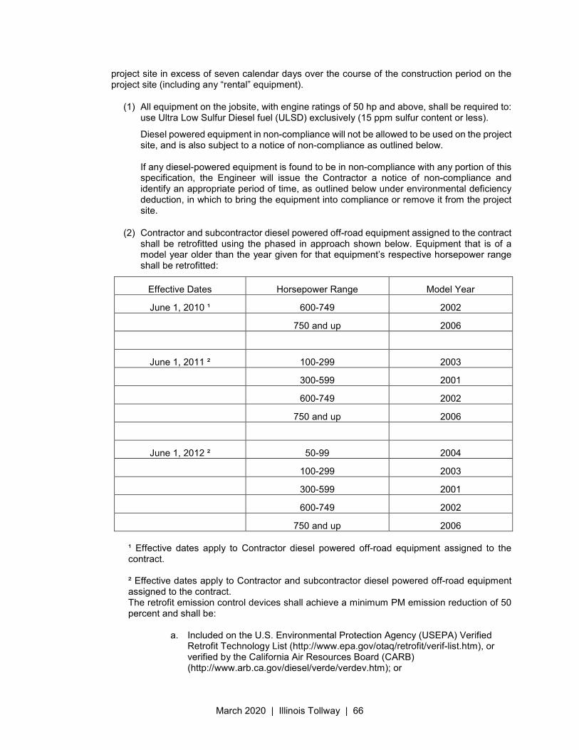
March 2020 | Illinois Tollway | 66
project site in excess of seven calendar days over the course of the construction period on the project site (including any “rental” equipment).
(1) All equipment on the jobsite, with engine ratings of 50 hp and above, shall be required to: use Ultra Low Sulfur Diesel fuel (ULSD) exclusively (15 ppm sulfur content or less).
Diesel powered equipment in non-compliance will not be allowed to be used on the project site, and is also subject to a notice of non-compliance as outlined below. If any diesel-powered equipment is found to be in non-compliance with any portion of this specification, the Engineer will issue the Contractor a notice of non-compliance and identify an appropriate period of time, as outlined below under environmental deficiency deduction, in which to bring the equipment into compliance or remove it from the project site.
(2) Contractor and subcontractor diesel powered off-road equipment assigned to the contract shall be retrofitted using the phased in approach shown below. Equipment that is of a model year older than the year given for that equipment’s respective horsepower range shall be retrofitted:
Effective Dates Horsepower Range Model Year
June 1, 2010 ¹ 600-749 2002
750 and up 2006
June 1, 2011 ² 100-299 2003
300-599 2001
600-749 2002
750 and up 2006
June 1, 2012 ² 50-99 2004
100-299 2003
300-599 2001
600-749 2002
750 and up 2006
¹ Effective dates apply to Contractor diesel powered off-road equipment assigned to the contract.
² Effective dates apply to Contractor and subcontractor diesel powered off-road equipment assigned to the contract. The retrofit emission control devices shall achieve a minimum PM emission reduction of 50 percent and shall be:
a. Included on the U.S. Environmental Protection Agency (USEPA) Verified
Retrofit Technology List (http://www.epa.gov/otaq/retrofit/verif-list.htm), or verified by the California Air Resources Board (CARB) (http://www.arb.ca.gov/diesel/verde/verdev.htm); or
March 2020 | Illinois Tollway | 67
b. Retrofitted with a non-verified diesel retrofit emission control device if verified retrofit emission control devices are not available for equipment proposed to be used on the project, and if the Contractor has obtained a performance certification from the retrofit device manufacturer that the emission control device provides a minimum PM emission reduction of 50 percent.
Note: Large cranes (Crawler mounted cranes) which are responsible for critical lift operations are exempt from installing retrofit emission control devices if such devices adversely affect equipment operation. Diesel powered off-road equipment with engine ratings of 50 hp and above, which are unable to be retrofitted with verified emission control devices or if performance certifications are not available which will achieve a minimum 50 percent PM reduction, may be granted a waiver by the Department if documentation is provided showing good faith efforts were made by the Contractor to retrofit the equipment. Construction shall not proceed until the Contractor submits a certified list of the diesel powered off-road equipment that will be used, and as necessary, retrofitted with emission control devices. The list(s) shall include (1) the equipment number, type, make, Contractor/rental company name; and (2) the emission control devices make, model, USEPA or CARB verification number, or performance certification from the retrofit device manufacturer. Equipment reported as fitted with emissions control devices shall be made available to the Engineer for visual inspection of the device installation, prior to being used on the jobsite. The Contractor shall submit an updated list of retrofitted off-road construction equipment as retrofitted equipment changes or comes on to the jobsite. The addition or deletion of any diesel-powered equipment shall be included on the updated list. If any diesel powered off-road equipment is found to be in non-compliance with any portion of this special provision, the Engineer will issue the Contractor a diesel retrofit deficiency deduction.
(b) Idling Restrictions. The Contractor shall establish truck-staging areas for all diesel-powered
vehicles that are waiting to load or unload material at the jobsite. Staging areas shall be located where the diesel emissions from the equipment will have a minimum impact on adjacent sensitive receptors. The Engineer will review the selection of staging areas, whether within or outside the existing highway right-of-way, to avoid locations near sensitive areas or populations to the extent possible. Sensitive receptors include, but are not limited to, hospitals, schools, residences, motels, hotels, daycare facilities, elderly housing and convalescent facilities. Diesel powered engines shall also be located as far away as possible from fresh air intakes, air conditioners, and windows. The Engineer will approve staging areas before implementation.
Diesel powered vehicle operators may not cause or allow the motor vehicle, when it is not in motion, to idle for more than a total of 10 minutes within any 60-minute period, except under any of the following circumstances:
(1) The motor vehicle has a gross vehicle weight rating of less than 8000 lb (3630 kg).
(2) The motor vehicle idles while forced to remain motionless because of on-highway traffic, an official traffic control device or signal, or at the direction of a law enforcement official.
(3) The motor vehicle idles when operating defrosters, heaters, air conditioners, or other equipment solely to prevent a safety or health emergency.
March 2020 | Illinois Tollway | 68
(4) A police, fire, ambulance, public safety, other emergency or law enforcement motor vehicle, or any motor vehicle used in an emergency capacity, idles while in an emergency or training mode and not for the convenience of the vehicle operator.
(5) The primary propulsion engine idles for maintenance, servicing, repairing, or diagnostic purposes if idling is necessary for such activity.
(6) A motor vehicle idles as part of a government inspection to verify that all equipment is in good working order, provided idling is required as part of the inspection.
(7) When idling of the motor vehicle is required to operate auxiliary equipment to accomplish the intended use of the vehicle (such as loading, unloading, mixing, or processing cargo; controlling cargo temperature; construction operations, lumbering operations; oil or gas well servicing; or farming operations), provided that this exemption does not apply when the vehicle is idling solely for cabin comfort or to operate non-essential equipment such as air conditioning, heating, microwave ovens, or televisions.
(8) When the motor vehicle idles due to mechanical difficulties over which the operator has no control.
(9) The outdoor temperature is less than 32 °F (0 °C) or greater than 80 °F (26 °C).
When the outdoor temperature is greater than or equal to 32 °F (0 °C) or less than or equal to 80 °F (26 °C), a person who operates a motor vehicle operating on diesel fuel shall not cause or allow the motor vehicle to idle for a period greater than 30 minutes in any 60-minute period while waiting to weigh, load, or unload cargo or freight, unless the vehicle is in a line of vehicles that regularly and periodically moves forward. The above requirements do not prohibit the operation of an auxiliary power unit or generator set as an alternative to idling the main engine of a motor vehicle operating on diesel fuel.
(c) Environmental Deficiency Deduction. When the Engineer is notified, or determines that an
environmental control deficiency exists, he/she will notify the Contractor in writing, and direct the Contractor to correct the deficiency within a specified time period. The specified time-period, which begins upon Contractor notification, will be from 1/2 hour to 24 hours long, based on the urgency of the situation and the nature of the deficiency. The Engineer shall be the sole judge regarding the time period.
The deficiency will be based on lack of repair, maintenance, diesel vehicle emissions control, diesel retrofit emissions control, and idling. If the Contractor fails to correct the deficiency within the specified time frame, a daily monetary deduction will be imposed for each calendar day or fraction thereof the deficiency continues to exist. The calendar day(s) will begin when the time period for correction is exceeded and end with the Engineer's written acceptance of the correction. The daily monetary deduction will be $1,000.00 for each deficiency identified. If a Contractor or subcontractor accumulates three environmental deficiency deductions in a contract period, the Contractor will be shut down until the deficiency is corrected. Such a shutdown will not be grounds for any extension of contract time, waiver of penalties, or be grounds for any claim
(d) Method of Measurement. Compliance with this specification will not be measurement for
payment.
March 2020 | Illinois Tollway | 69
(e) Basis of Payment. Any costs associated with bringing any diesel-powered equipment into compliance with these diesel vehicle emissions controls shall be considered as included in the contract unit prices bid for the various items of work involved and no additional compensation will be allowed. The Contractor's compliance with this notice and any associated regulations shall also not be grounds for a claim.
107.38 Responsibility for Damage Claims. To the fullest extent permitted by law, the Contractor shall be responsible for any injury to person or damage to property due to the activities of the Contractor, its Subcontractor(s) or sub-Subcontractor(s), and their agents and employees with respect to The Work or in connection therewith, and the Contractor shall indemnify and save harmless the Illinois Tollway, its directors, officers, employees and its Consulting Engineer, from any and all claims, suits, actions, and costs, fees, and expenses of every nature or description, arising from, growing out of or connected with The Work, or on account of or in consequence of any act or omission in safeguarding The Work, or on account of or in consequence of using unacceptable materials in performing The Work, or because of any act or omission, neglect or misconduct of the Contractor and its Subcontractors or sub-Subcontractors and their agents and employees, or because of any claims or amount recovered by reason of their infringement of any patent, trade mark or copyright or by reason of their violation of any law, ordinance, regulation, rule order or decree, and such indemnity shall not be limited by reason of the enumeration of any insurance coverage hereinafter provided.
Nothing herein contained shall be construed as prohibiting the Illinois Tollway, its directors, officers, employees and agents or its Consulting Engineer from defending any claims, actions or suits brought against them or any of them, through the selection and use of their own agents, attorneys and experts. The Contractor shall be liable for all costs, fees and expenses incurred by the Illinois Tollway, or its directors, officers, employees and agents or its Consulting Engineer in their defenses of any such claims, actions, or suits.
It is understood and agreed that the Contractor is an independent contractor and as such is responsible for any and all of its activities hereunder.
In the event any such claim, suit or action is asserted, the Illinois Tollway is authorized to withhold from any monies due or to be due the Contractor, the value of such claim, suit or action as determined by the Illinois Tollway as necessary to be retained by the Illinois Tollway for said purpose, or in case no money or insufficient money is due, the Surety or Sureties shall pay for said costs, fees and expenses and be bound until such suits, actions or claims have been settled or have been finally judicially determined.
107.39 Accident Reports. The Contractor shall immediately notify the Engineer in the event of any injury to persons or damage to property arising in connection with The Work. The Contractor shall send a written report to the Engineer, the Chief Engineering Officer, the Illinois Tollway’s Legal Department, and to the Contractor’s insurance carrier setting forth a full and precise statement of facts pertaining to any accident or other event resulting in injury to any person or damage to property, and which arises from or involves any action or failure to act by the Contractor, its Subcontractors, or any employee or agent of either as a consequence of the performance of the Contract. Such report shall be made within 24 hours after the occurrence and shall include a list of names and addresses of all known witnesses to the accident or event. The Contractor shall also immediately send to the Chief Engineering Officer and the Illinois Tollway’s Legal Department a copy of any summons, subpoena, notice, or other document served upon or received by the Contractor or any Subcontractor, or any agent, employee, or representative of either, in connection with any matter before any court, arising in any manner from the Contract or the performance of the Contract. Reports or documents required to be sent to the Chief Engineering Officer and the Illinois Tollway’s Legal Department shall be sent to the Illinois Tollway’s office at 2700 Ogden Avenue, Downers Grove, Illinois 60515.
The Contractor shall be responsible to the Illinois Tollway for any losses or damages which the Illinois Tollway sustains as a result of the Contractor’s failure to give notice as required herein.
March 2020 | Illinois Tollway | 70
107.40 Regulatory Compliance. The Contractor shall perform The Work in this Contract in accordance with all local, state and federal regulations. This includes:
(a) DOT: U.S. Department of Transportation, including but not limited to:
(1) Hazardous Substances, Title 49, Parts 171 & 172 of Code of Federal Regulations.
(2) Hazardous Materials Regulations, General Awareness and Training Requirements for Handlers, Loaders and Drivers, Title 49, Parts 171-180 of Code of Federal Regulations.
(b) EPA: U.S. Environmental Protection Agency (EPA), including but not limited to:
(1) Resource Conservation and Recovery Act (RCRA), 42 USC 6921, 6941 to 6954 (Subtitle D).
(2) Title 40, Parts 260 to 279 of the Code of Federal Regulations.
(3) 40 CFR 240 to 258
(c) FAA: U.S. Department of Transportation, Federal Aviation Administration Division, including but not limited to:
(1) Small Unmanned Aircraft Systems (UAS) Rule (14 CFR part 107), The contractor must obtain authorization for flight under FAA's Drone Zone portal or the Low Altitude Authorization and Notification Capability (LAANC) program. Once approved, the contractor must submit the UAS request to uas.illinoisvirtualtollway.com. The contractor agrees it will operate the UAS solely for purposes traceable to the scope of the Contract. Guidance on the usage of UAS can be found in the following website; https://www.faa.gov/uas/getting_started/part_107/
(d) State: State of Illinois, including but not limited to:
(1) 35 Illinois Administrative Code (IAC) 702, 703, and 810
(2) Illinois Environmental Protection Act
(3) Illinois Solid Waste Management Act
(4) Illinois Complied Statutes (ILCS) 415
(e) Local: Abide by all local requirements, which govern the management, hauling and disposal of hazardous and non-hazardous waste.
(f) All work shall meet or exceed the requirements of all federal state and local authorities exercising jurisdiction over construction of work and the project.
March 2020 | Illinois Tollway | 71
Illinois State Toll Highway Authority
SUPPLEMENTAL SPECIFICATION FOR
SECTION 108. PROSECUTION AND PROGRESS
Issued April 1, 2016 Revised March 23, 2020
This Supplemental Specification amends and supersedes the provisions of the Illinois Department of Transportation Standard Specifications for Road and Bridge Construction, adopted April 1, 2016 and shall be construed to be a part thereof, superseding any conflicting provisions thereof applicable to the work under the contract.
Delete Section 108 in its entirety and replace with the following.
108.01 Subletting of Assignment of Contract. The Contractor shall furnish the material, labor, equipment, and all incidentals necessary to perform, with its own organization, work items accounting for not less than 35 percent of the total Contract Award amount, based on quantities of items and unit prices contained in the Proposal. Except for the transporting of materials, no portion of the Contract shall be sublet, assigned or otherwise disposed of except with the written consent of the Chief Engineering Officer. All Subcontractors must be approved in writing before they commence any work. Approval in writing of a Subcontractor shall be construed as approval for the Contractor’s subletting of that portion of The Work to be done by the Subcontractor. Subcontractors shall be considered and recognized only as agents, employees or workers of the Contractor and shall be subject to the same requirements as to character and competence as the Contractor. Subcontractors shall not be third party beneficiaries of the Contract. Requests for approval of Subcontractors shall show the nature and percentages of The Work to be done by each Subcontractor, to be computed based on the value of proposed quantities of Contract work items and unit prices to be subcontracted in relation to the total Contract amount. The Contractor shall not, under any circumstances, be relieved of its full and complete liability and obligations for The Work due to such subcontracting, and the Engineer shall not be required to deal directly with Subcontractors.
The Contractor agrees to bind every subcontractor to the terms and conditions of the Contract as far as applicable to The Work of such subcontractor and, in order that such subcontractor shall be so bound, the Contractor agrees to incorporate in every subcontract let by him a clause substantially as follows in which clause the term “General Contractor” shall be deemed to refer to the Contractor:
“All Subcontractors agree to be bound to the General Contractor by all the terms of the Contract between the Illinois Tollway and the General Contractor, including all Contract Documents, and to assume toward the General Contractor all the obligations and responsibilities that the General Contractor by such documents has assumed toward the Illinois Tollway. A copy of the complete Contract between the Illinois Tollway and the General Contractor is available from the Illinois Tollway for a reasonable, standard fee. The Subcontractor agrees that the General Contractor shall at all times have the right to assign this Contract to the Illinois Tollway and that, regardless of such assignment, the Illinois Tollway shall at all times have the right to cancel this subcontract upon the same terms and conditions as are contained in the Contract between the Illinois Tollway and the General Contractor. It is understood and agreed that nothing in this clause is intended to give any Subcontractor or supplier, or any employee thereof, any right of action against the Illinois Tollway on this Contract or the Contract between the Illinois Tollway and the General Contractor. The Subcontractor further agrees to bind to it any sub-subcontractor under its contract by all terms and conditions contained in the Contract between the Illinois Tollway and the General Contractor as far as applicable to the work of said sub-Subcontractor, and in order that said sub-subcontractor shall be so bound, the Subcontractor agrees to incorporate in every sub-subcontract which it lets a clause containing substantially the provisions contained herein. It is further understood that in the event there are any inconsistencies or conflicts between the terms and provisions of this paragraph and any other provision of the Contract between the General and Subcontractor, the terms and provisions of this paragraph shall
March 2020 | Illinois Tollway | 72
prevail and control and be binding on the parties.”
108.02 Progress Schedule Requirements.
(a) Baseline Schedule. The Contractor shall submit to the Engineer within 14 Calendar days of the issuance of the Notice to Proceed, a Baseline Schedule which shall be in accordance with the provisions outlined herein. The Engineer will review the Baseline Schedule and provide a response to the Contractor within 14 Calendar days from the submittal date. If the Engineer is going to reject a Baseline Schedule, the Engineer will call a meeting with the Contractor in order to discuss the deficiencies in an attempt to more quickly reach resolution and obtain an acceptable Baseline Schedule. The Contractor will be required to make corrections to the Baseline Schedule to comply with the contract requirements and will adjust the Baseline Schedule to incorporate any missing information requested by the Engineer within 14 calendar days. Payment for the Work will be withheld until a Baseline Schedule has been submitted and accepted by the Engineer unless the Engineer has not provided responses to the Baseline Schedule submittal within 14 calendar days of the submittal; however, Mobilization may be paid according to Article 671.02(a).
The Baseline Schedule shall utilize the latest version of Primavera as the scheduling software package. A waiver to the Primavera software can be requested prior to the start of the contract. Approval of the alternative software by the Engineer may be granted provided the substitution is comparable to the latest Primavera software and the alternate software and licenses are provided to the Engineer. The Baseline Schedule shall clearly and separately define the progression of Work from the Notice to Proceed date to the Contract Completion Date by using separate activities for all work components. The schedule shall be in sufficient detail to allow evaluation of progress of all work activities.
If the Baseline Schedule has not been accepted within 30 calendar days after the original submittal, and the Engineer has provided responses to the Baseline Schedule submittal within 14 calendar days of the submittal, the Contractor shall provide the Engineer with a corrective action plan. This plan shall include resumes for the proposed scheduler(s) for acceptance by the Engineer. The proposed scheduler(s) shall have experience developing and updating CPM schedules for projects of similar magnitude and scope. The Baseline Schedule shall consist of the following items:
(1) A Schedule Narrative that describes the critical path(s) of the project, outlines the Contractor’s approach to complete the work, defines the project calendars and identifies critical resources. Updated Schedule Narratives will also be required for each monthly update and Revised Baseline Schedules.
(2) Activity description shall be descriptive to identify its intent, including location of work.
(3) Activity Durations for construction activities in excess of 30 calendar days will not be allowed.
(4) Activity Calendar-Types: The Contractor must coordinate working hours with local townships and municipalities and plan its work in accordance with local ordinances and Article 107.35, unless written waivers can be obtained by the Contractor from the township/municipality. If winter period slow-downs or winter period shut-downs are allowed or specified on a project, the non-work periods are to be shown using the project calendar and not through the inclusion of a winter period slow-down or winter period shut-down activity.
(5) Each scheduled activity shall show the intended rate of production for each item of work.
March 2020 | Illinois Tollway | 73
(6) The Contractor shall provide additional schedule tasks as requested to assist the Engineer with communicating how its work will impact local communities and traffic.
(7) The Contractor shall consider and include in the schedule planning and scheduling of all work, seasonal weather conditions, utility coordination, expected job learning curves, and work of other contractors. The National Oceanic and Atmospheric Administration’s (NOAA) National Weather Service or Weather Underground will be used as a comparison to evaluate seasonal weather conditions. The inclusion of weather days in the schedule should be described in the Project Narrative.
(8) Predecessor and Successor Activity Logic: Standard Finish-to-Start logic without lags should be used when developing and updating Project Schedules. Other logic types such as Start-to-Start and Finish-to-Finish and any lags must be identified and justified in a general narrative and are subject to review and acceptance by the Engineer.
(9) The Contractor must submit a schedule in Portable Document Format (.pdf) and in a condensed native file format of the schedule software application (Example .xer) as part of every schedule submittal to the Engineer.
(10) The Baseline Schedule shall show no progress and the Data Date shall be the same date as the actual Notice to Proceed date. The Notice to Proceed shall be the first activity on the schedule. As an option the Contractor may utilize the Notice of Intent to Award date as the first activity on the schedule in order to start project documentation but may not start any ‘physical’ work until the actual Notice to Proceed has been received.
(11) The Contractor shall develop the Baseline Schedule to coincide with the Staging/Phasing plan contained within the contract documents. Should the Contractor request a deviation from the staging/phasing plan outlined in the contract, prior approval must be secured from the Engineer before it is contained in the Baseline Schedule. The Contractor should submit any such requests for deviation to the Engineer, who will coordinate through the Illinois Tollway Project Manager. The Contractor must continue to schedule the project to coincide with the latest approved phasing/staging plan while the request is under consideration by the Engineer. The Baseline Schedule will not be accepted with an alternative staging plan until the Engineer has accepted the revised plan. The Baseline Schedule submittal is not considered the appropriate method of requesting a revised staging plan.
(12) Multiple schedule calendars should be used to accommodate specific imposed installation constraints.
(13) Start constraints and finish milestones are to be included to meet the requirements included in the contract. Early Start and Late Finish constraints, respectively, are to be applied according to Contract requirements. Mandatory or Expected constraints should not be used. Constraints not identified in the Contract are discouraged and may not be accepted.
(14) All Contractual Milestones must be shown on the Baseline Schedule and should be clearly identifiable by Special Provision number in the Activity Description (i.e. S.P. 103.1 - Contract Completion, Substantial and Interim Completions dates).
(15) The Baseline Schedule cannot contain negative float.
(16) The Baseline Schedule shall be submitted in the schedule review process through the Web Based Program Management system for subsequent review and acceptance.
March 2020 | Illinois Tollway | 74
(17) The Baseline Schedule shall include all work to be executed on the contract.
The Baseline Schedule shall include, in addition to all activities required to execute work, such tasks as permits, agency permit approvals and access constraints, Right-of-Way (ROW) acquisition requirements, known utility coordination, owner defined access constraints as described in the bid documents, mobilization, demobilization, punchlist, submittals, submittal review by the Engineer and approval of material samples and shop drawings, procurement of significant materials and fabrication of special items, as well as installation and testing. The Engineer will have 14 calendar days from receipt of the submittal to review the schedule.
The activities shall be sufficiently detailed so that a reviewer can readily follow the sequence. The activities are to be described so that work is readily identifiable. All activities, with the exception of the Notice to Proceed, the Notice of Intent to Award and the project completion milestone shall have at least one predecessor and one successor, respectively. No open-ended schedules will be permitted without prior approval of the Engineer.
The Contractor's accepted Baseline Schedule shall be subject to updates in accordance with the “Monthly Schedule Update” as described in Article 108.02(c). The current accepted Baseline Schedule will be used to evaluate potential Contractor Time Extension Requests.
When the total contract dollar value is over $10 million, the Contractor is required to check their Baseline Schedule and subsequent Monthly Progress Schedules using Schedule Analyzer Pro, or other approved equal analyzing software, prior to submitting to the Engineer. The report produced by the analyzing software shall accompany each schedule.
(b) Revised Baseline Schedule (RBS). If the Contractor requests changes to the accepted Baseline Schedule or when actual critical path contains 14 or more Calendar days negative float and the Contractor has not submitted a Request for Extension of Time per 108.08, the Contractor shall submit a Revised Baseline Schedule which shall show actual project history and the Contractors proposed plan to complete the balance of the work by the contract completion dates. The Revised Baseline Schedule shall include all project work completed to date. Completed work must not be removed from any schedule. The Revised Baseline Schedule shall be submitted in the schedule review process through the Web Based Program Management system for subsequent review and acceptance within 14 Calendar Days of the Engineer’s request and shall be subject to review and acceptance by the Engineer. The Engineer will have 14 Calendar days from receipt of the submittal to review the schedule. If the Engineer is going to reject a RBS, the Engineer will call a meeting with the Contractor in order to discuss the deficiencies in an attempt to more quickly reach resolution and obtain an acceptable RBS. Upon the Engineer’s acceptance of the RBS, this schedule will be deemed the current Baseline Schedule. Payment will be withheld until a satisfactory schedule has been submitted and accepted by the Engineer.
The Revised Baseline Schedule submittal shall be consistent with all requirements of the Baseline Schedule submittal (See Article 108.02(a)) and the narrative shall detail how the Contractor intends to recover lost time and bring the project back on schedule in order to comply with the contract completion dates. The Revised Baseline Schedule cannot contain negative float.
(c) Monthly Schedule Update (MSU). After acceptance of the Contractor's Baseline Schedule, the Contractor shall monitor progress of The Work and update the schedule 30 Calendar Days from the date of acceptance and every 30 Calendar Days thereafter no later than the 10th calendar day of each month thereafter to reflect actual progress. Completed work must not be removed from the MSU. The MSU will be used as the basis for reviewing the Contractor’s monthly progress. The purpose of the MSU is to report progress in accordance with the latest accepted schedule and is not to be used to revise the schedule logic, resources, durations or constraints. If the Engineer is going to reject a MSU, the Engineer will call a meeting with the Contractor and
March 2020 | Illinois Tollway | 75
CM in order to discuss the deficiencies in an attempt to more quickly reach resolution and obtain an acceptable MSU.
A progress narrative shall be submitted along with the Contractor’s Monthly Schedule Update, which describes progress made since the last Monthly Schedule Update submittal with special emphasis on critical and near critical activities, actual and potential delays to contract milestones and the utilization of any critical resources. The Contractor shall outline in the progress narrative its plan for executing The Work for the next 30 Calendar days. Monthly Schedule Updates shall be submitted in the schedule review process through the Web Based Program Management system.
The Contractor shall make every Monthly Schedule Update submittal consistent with all Contract requirements and use all practicable means to make the progress of The Work conform to the logic included in the latest accepted schedule. If the Contractor falls behind the scheduled progress as a result of its actions, it shall take appropriate action to provide schedule recovery plans and other necessary measures to meet the contract specified completion dates in accordance with Article 108.02(b).
In accordance with the Illinois Tollway’s Supplemental Specifications, where the Contractor believes the cause of a delay is beyond their control, the Contractor shall identify and promptly report to the Engineer progress delays during the prosecution of the work. If the Contractor has an outstanding Time Extension Request affecting any Interim, Substantial or Final Completion dates, the Contractor’s Monthly Schedule Update may contain negative float provided there is opportunity for the contractor to recover lost time. Within 14 Calendar days following the Chief Engineering Officer’s determination of the Time Extension Request, the Contractor shall provide a Revised Detailed Schedule to the Engineer that reflects the Chief Engineering Officer’s disposition of the Contractor’s Time Extension request. The Contractor shall continue to submit Monthly Schedule Updates, which may include negative float, throughout any delay or pending any time extension requests/approvals.
Monthly Schedule Updates may be suspended or the frequency reduced, with prior approval of the Engineer and Illinois Tollway Project Manager, after the Contract has reached the “Substantial Completion Date” or during periods of suspended work. A Final or As Built Monthly Progress Schedule shall be submitted to the Engineer within 30 calendar days after the project has reached Final Contract Completion. The Final or As Built Schedule shall include all tasks (including approved extra work) accomplished during the life of the project. Final Payment will be withheld until a satisfactory schedule has been submitted and accepted by the Engineer.
(d) Measurement and Payment. There will be no separate measurement or payment for fulfilling the requirements described herein, and all costs, direct or indirect, shall be included in the prices for other items. Failure to provide satisfactory schedule submittals within the time specified herein will result in Liquidated Damages, per Article 108.02(e), being assessed and will result in payment being withheld until such time as the Contractor fulfills the requirements.
(e) Liquidated Damages. The Contractor shall be subject to liquidated damages in the amount of $300 per day, for contracts valued under $25 million, and the amount of $600 per day, for contracts valued over $25 million, for each and every calendar day the Contractor is delinquent in the submission of the Baseline Schedule, the Revised Baseline Schedule or the Monthly Schedule Update as required by these specifications.
108.03 Prosecution of Work. The Contractor shall begin the work in accordance with Article 103.08. The Work shall be prosecuted in such a manner and with such a supply of materials, equipment and labor as is considered necessary to ensure its completion according to the time specified in the Contract.
The Contractor shall notify the Engineer at least 24 hours in advance of either discontinuing or
March 2020 | Illinois Tollway | 76
resuming operations.
108.04 Reserved
108.05 Date for Completion. The Contractor shall complete The Work on or before the Completion Date and in accordance with S.P. 103 for any Substantial and Interim Completion dates. The Illinois Tollway will give the Contractor prompt written notice of any change in the Completion Date.
If the Contract shall be revised in any material respect or, in the sole judgment of the Illinois Tollway, changes become necessary in the best interests of the project due to circumstances not known at the time the Contract was entered into or arising thereafter, and the Illinois Tollway determines that such revision or revisions will cause a material delay in the completion of The Work, the Illinois Tollway will extend the Completion Date by the number of days it determines to be equitable. The Chief Engineering Officer will not be required to consider the Contractor’s request, if any, for extensions of time beyond the Completion Date for causes set forth in this Article unless such request is submitted to the Chief Engineering Officer in writing within 10 calendar days of notice to the Contractor of the duration of the extension originally granted by the Illinois Tollway. The Chief Engineering Officer will rule on such request promptly following completion of all the Work in the Contract, and such decision shall be final. Nothing herein shall be deemed to permit the Contractor to suspend any work pending a decision on the Contractor’s request for extension of the Completion Date or as a result of a disagreement as to any extension of time granted.
The Contractor shall not be entitled to extra compensation or damages for delays, disruption or acceleration caused by such changes, but shall only be entitled to seek an extension of time for completion of the Contract.
108.06 Labor, Methods and Equipment. The Contractor shall at all times employ sufficient labor and equipment for prosecuting all items and phases of work to full completion in the manner and time required by these Specifications and the Contract.
All workers shall have sufficient skill and experience to properly perform all portions of The Work assigned to them. Workers engaged in special work or skilled work shall have sufficient specialized experience in such work and in the operation of the required equipment to perform all work on time and in a proper and safe manner.
Any person employed by the Contractor or by any subcontractor who, in the opinion of the Engineer, does not perform work in a proper and skillful manner or is intemperate or disorderly shall, at the written request of the Engineer, be removed forthwith by the Contractor or subcontractor employing such person, and shall not be employed again on any portion of The Work without the approval of the Engineer.
Should the Contractor fail to remove such person or persons as required above, or fail to furnish suitably skilled and sufficient personnel for the proper prosecution of The Work, the Engineer may suspend The Work by written notice until the Contractor employs proper and sufficient personnel for The Work. Should the Contractor fail, within a reasonable time, to employ sufficient and/or properly skilled personnel for the prosecution of The Work, the Engineer may take such actions and remedies as are provided in Article 108.07. All equipment which is proposed to be used on The Work shall be of sufficient size and in such mechanical condition as to meet requirements of the Contract and to produce work that meets or exceeds the quality of work required by the Contract. Equipment used on any portion of the project shall be such that no injury to the roadway, adjacent property, or other highways will result from its use.
The Contractor shall prosecute The Work for the number of days per week and the number of hours per day as are necessary to fulfil the requirements of the Substantial Completion Date and any Interim Completion Dates as specified in S.P. 103, and complete The Work by the Completion Date. If in the opinion of the Engineer the actual progress on The Work falls behind the projected progress as outlined in the approved Progress Schedule, or if it becomes apparent that the construction progress is such that The Work or the various stages thereof will not be completed within the specified time or times, the Contractor
March 2020 | Illinois Tollway | 77
shall implement, at the direction and with the approval of the Engineer, any or all of the following at no additional cost to the Illinois Tollway:
(a) Provide additional equipment for The Work.
(b) Add necessary additional manpower.
(c) Increase working hours up to a maximum 24 hours per day including Saturdays, Sundays, and holidays subject to any restrictions which may be set forth in the Special Provisions.
(d) Accelerate all or portions of The Work.
(e) Adjust the Sequencing and order of The Work.
(f) Undertake revised Work methods.
When the methods and equipment to be used by the Contractor in performing The Work are not prescribed in the Contract, the Contractor is free to use any reasonable methods or equipment to perform The Work, as long as it demonstrates to the satisfaction of the Engineer that such methods or equipment will accomplish The Work in conformity with the requirements of the Contract.
When the Contract specifies that the construction be performed by the use of certain methods and equipment, such methods and equipment shall be used unless others are authorized in writing by the Engineer. If the Contractor desires to use a method or type of equipment other than that specified in the Contract, it may request authority from the Engineer to do so. The request shall be in writing and shall include a full description of the methods and equipment proposed to be used and an explanation of the reasons for desiring to make the change. The Contractor shall, in no event, be entitled to or have a right to such substitutions. If authorization is given, it will be on the condition that the Contractor will be fully responsible for carrying out The Work in conformity with the Contract requirements. If, after use of the substituted methods or equipment, the Engineer determines that the work produced does not meet the Contract requirements, the Contractor shall discontinue the use of the substitute method or equipment and shall complete all remaining work with the specified methods and equipment. The Contractor shall also remove any resulting deficient work and replace it with work of the specified quality, or take such other corrective action as the Engineer may direct. No change will be made in the basis of payment for the construction items involved, or in the Completion Date, as a result of the authorization of any changes in methods or equipment under these provisions.
108.07 Temporary Suspension of Work. The Engineer shall have the authority to suspend, delay or interrupt all or any part of The Work as he may deem necessary due to conditions unfavorable for satisfactory prosecution of The Work, or to other conditions which, in his opinion, warrant such action; or for such time as is necessary by reason of failure on the part of the Contractor to carry out orders given or to otherwise perform in accordance with any or all provisions of the Contract. The Engineer will notify the Contractor in writing of all such suspensions, delays or interruptions.
If a suspension, delay or interruption of all or any part of The Work is ordered by the Illinois Tollway for the sole convenience of the Illinois Tollway and exceeds, in the sole judgment of the Illinois Tollway, a reasonable period of time, an adjustment may be made in the Contract price for any increase in actual cost, exclusive of profit, to the Contractor for performance of The Work delayed due to such extraordinary suspension, delay or interruption. However, no such adjustment as provided herein, will be made for any suspension, delay, or interruption of all or any part of The Work if the performance thereof by the Contractor would have been so suspended, delayed or interrupted by any other cause, including failure on the part of the Contractor to carry out orders given or to perform in compliance with any or all provisions of the Contract; or if an equitable adjustment for the suspension, delay or interruption is provided for under any other provision of the Contract. Nothing herein shall permit the Contractor to recover costs for delays which could have been avoided by diligent prosecution of The Work or for suspensions of The Work due to seasonal
March 2020 | Illinois Tollway | 78
conditions unfavorable for the prosecution of The Work.
If there is a suspension, delay or interruption of all or any part of The Work in accordance with this Article, the Contractor shall store all materials in such a manner that they will not obstruct or impede the traveling public or become damaged in any way. The Contractor shall take every precaution to prevent damage to or deterioration of any work that has been done; shall provide suitable drainage of the roadway; and shall erect temporary structures where necessary.
The Contractor shall not suspend, delay or interrupt all or any part of The Work without written authority from the Engineer.
After all or any part of The Work has been suspended, delayed or interrupted by the Engineer or by the Contractor with written authority from the Engineer, the Contractor shall not resume operations until notified in writing to do so by the Engineer. The Contractor may apply for extensions of time therefore as provided in Article 108.05.
108.08 Request for Extension of Time.
(a) Extra Work, Change Orders and Supplemental Agreements. Time is of the essence and the Contractor is required to complete all The Work, including Extra Work Orders and Change Orders, changes involving supplemental agreements, and as provided for in Article 104.02, by the Completion Date unless an extension of time is requested and approved according to the provisions of this Article. If the Contractor fails to complete The Work by the Completion Date, the Illinois Tollway shall be entitled to compensation for such delay in accord with Article 108.09.
When such additional, extra and/or altered work is of such a character or magnitude, in the sole judgment of the Illinois Tollway, the amount of time reasonably necessary to perform The Work as so revised extends beyond the Completion Date, the Completion Date may be extended by the Illinois Tollway prior to commencement of the extra or altered work. When the Contractor deems that an extension of time is due for revisions in the work required to be performed or materials required to be furnished, it shall notify the Illinois Tollway in writing of its intention to make a request for such extension of time before it begins that portion of The Work or furnishes the materials which the revisions affect and prior to approval by the Illinois Tollway of a Change Order or Extra Work Order related to such Work. The Chief Engineering Officer shall consider and rule upon all such requests for extensions of time and the decision of the Chief Engineering Officer shall be final. In the event the Contractor does not give written notification to the Illinois Tollway of its request for an extension of time prior to the commencement of the revised, extra or altered work, within a reasonable amount of time and prior to approval by the Illinois Tollway of a Change Order or Extra Work Order related to such Work, the Contractor shall be deemed to have waived any and all of its legal or equitable rights for an extension of time to complete The Work.
Unless otherwise expressly agreed to by the Illinois Tollway, the Contractor shall not be entitled to extra compensation or damages for any extra time, disruption, acceleration and other costs required for completion of The Work due to Extra Work, Change Orders, or Supplemental Agreements, but shall be fully compensated for such extra time, disruption, acceleration and other costs incurred by the payments provided for work contained in the Extra Work Orders, Change Orders or supplemental agreements.
(b) Unforeseen Delays. When a material delay occurs due to unforeseen causes beyond the control and without the fault or negligence of the Contractor, including, but not restricted to, acts of God, acts of a public enemy, fires, flood, epidemics, strikes (except those caused by improper acts or omissions of the Contractor), extraordinary delays in delivery of materials caused by strikes, lockouts, wrecks, freight embargoes or governmental acts, the time of completion shall be extended for whatever period is determined by the Illinois Tollway to have resulted from such
March 2020 | Illinois Tollway | 79
causes. No extension of time on account of a delay due to unforeseen causes will be granted if written application therefore is not filed with the Chief Engineering Officer within ten Business Days of the date of termination of the delay or prior to the Completion Date whichever shall be sooner. Such request for extension of time, if timely filed, will be considered and ruled on promptly by the Chief Engineering Officer.
An “Act of God” means an earthquake, flood, cloudburst, tornado, or other cataclysmic event beyond the power of the Contractor to foresee or to make preparation for. Any rains, floods, windstorms, or other natural phenomena of reasonable expectancy, based on NOAA National Weather Service, for the particular locality and for the particular season of the year in which The Work is being prosecuted, are not “Acts of God”, and no extension of time will be granted for the delays resulting therefore.
In the event that The Work to be performed by the Contractor is materially delayed, obstructed, or hindered on account of any acts or omissions of the Illinois Tollway or its agents or employees, or any other contractors employed by the Illinois Tollway, the Contractor shall not be entitled to assert any claim or demand for additional compensation or otherwise against the Illinois Tollway, but in such event, the Contractors sole remedy shall be to seek an extension of time pursuant to this Article. The Contractor agrees to make no claim for damages or additional compensation for delay, disruption or acceleration in the performance of this Contract occasioned by any act or failure to act of the Illinois Tollway or any of its representatives or other Contractors or because of any injunction which may be brought against the Illinois Tollway or its representatives or other Contractors and agrees that the Contractor’s sole remedy shall be to seek an extension of time for completion of The Work, as provided herein, to be ruled upon after completion of all work under the Contract.
No extension of time will be granted for any delay or suspension of The Work due to the fault of the Contractor. The Illinois Tollway may suspend The Work in whole or in part, through no fault of the Contractor as provided in Article 108.07.
108.09 Liquidated Damages for Delay. The Contractor and the Illinois Tollway agree that the Illinois Tollway will suffer monetary damages in the event that The Work is not completed by the Completion Date, the Substantial Completion Date and any Interim Completion Date defined in S.P.103, the amount of which may later be difficult to prove or quantify. Therefore, it is the desire of the Illinois Tollway and the Contractor to establish and agree in advance as to the amount of damages reasonably assessable due to delay of the Contractor in completing The Work. Accordingly, the Contractor shall pay to the Illinois Tollway the applicable sum listed in the Special Provisions, as liquidated damages, for each and every calendar day that The Work, or any part thereof, remains uncompleted beyond the Completion Date. The Contractor waives any right to claim that the amount of damages, agreed to in the Special Provisions, is excessive or a penalty.
The Contractor shall not be excused from the assessment and payment of liquidated damages as provided in the Special Provisions merely because a portion of The Work is available for use by the Illinois Tollway or has been opened to traffic, so long as all The Work is not completed and accepted according to the Contract.
Unless the Contract Documents provide that the Contractor is not subject to liquidated damages during certain periods when it is not actually engaged on The Work, the Contractor shall be liable for liquidated damages as established in this Article and the Special Provisions for the entire period that The Work is not completed and approved beyond the Completion Date, even though said period may extend into the winter months beyond the normal construction season.
The Contractor shall also be liable for additional liquidated damages for failure to comply with or meet critical staging or schedules as may be set forth in the Special Provisions.
March 2020 | Illinois Tollway | 80
The Illinois Tollway may recover any and all liquidated damages by deducting the amount thereof out of any monies due or that may become due the Contractor, notwithstanding any liens, notices of liens or actions of subcontractors, and if said monies be insufficient to cover said damages, then the Contractor or the Surety shall promptly pay any remaining amounts due.
Nothing herein contained shall be construed as limiting the rights of the Illinois Tollway to also recover from the Contractor any and all other amounts due or to become due the Illinois Tollway, or any and all costs and expenses sustained by the Illinois Tollway for improper performance hereunder, or for breach or breaches in any other respect including, but not limited to, defective workmanship or materials.
108.10 Events of Default and Remedies. The occurrence and continuance of any of the following events shall constitute an “Event of Default” under the Contract.
(a) failure of the Contractor to comply with or perform any of the terms, conditions, provisions, or requirements of the Contract and to remedy such default within 10 calendar days after written notice thereof from the Chief Engineering Officer to the Contractor; or
(b) repeated violations by the Contractor of the same or similar Contract terms, conditions, provisions, or requirements, upon notice thereof from the Chief Engineering Officer, whether or not such violations are cured or cease to exist after notice in each instance; or
(c) if the Contractor admits insolvency or bankruptcy or inability to pay debts as they mature, or is generally not paying debts as such debts become due or makes an assignment for the benefit of creditors or applies for or consents to the appointment of a trustee, custodian, or receiver for the Contractor, or for the major part of its property; or
(d) if bankruptcy, reorganization, arrangement, insolvency or liquidation proceedings, proceedings under Title 11 of the United States code, as amended, or other proceedings for relief under any bankruptcy law or similar law for the relief of debtors are instituted by or against the Contractor (other than bankruptcy proceedings instituted by the Contractor against third parties), and, if instituted against the Contractor, are allowed against the Contractor or are consented to or are not dismissed, stayed, or otherwise nullified within 30 Calendar Days after such institution.
Upon the occurrence and during the continuance of any Event of Default under the Contract, the Illinois Tollway shall have the following rights and remedies, in addition to any other remedies provided in the Contract or by law.
(a) the Illinois Tollway may cancel the rights of the Contractor under the Contract and call upon the Surety to complete The Work in accordance with the terms of the Contract; or
(b) the Illinois Tollway may cancel the rights of the Contractor under the Contract and take over The Work, or any part thereof, including any or all materials and equipment within The Work areas as may be suitable and acceptable, and complete The Work by or on its own Force Account; or
(c) the Illinois Tollway may cancel the rights of the Contractor under the Contract and enter into a new Contract, with or without competitive bidding, for the completion of The Work, or any part thereof, which was to be performed by the Contractor under the Contract.
All costs, fees and expenses incurred by the Illinois Tollway, together with the cost of completing The Work under Contract, may be deducted from any monies due or which may become due on such Contract. In the event the costs, fees and expenses incurred by the Illinois Tollway shall be less than the sum which would have been payable under the Contract if it had been completed by the Contractor, the Contractor or the Surety, as the case may be, shall be entitled to receive the difference less liquidated damages, if any, as provided in Article 108.02, subject to any claims for liens thereon which may be filed with the Illinois Tollway, or any prior assignment filed with it. In the event that such costs fees and expenses shall exceed
March 2020 | Illinois Tollway | 81
the sum which would have been payable under the Contract, the Contractor and the Surety shall be liable therefore and shall promptly pay to the Illinois Tollway the amount of such excess, including amounts due for liquidated damages for delay pursuant to Article 108.09.
No remedy conferred upon or reserved to the Illinois Tollway pursuant to these Specifications or the Contract is intended to be exclusive of any other remedy or remedies, and each and every such remedy shall be cumulative, and shall be in addition to every other remedy given hereunder or now or hereafter existing at law or in equity or by statute.
108.11 Termination of Contractor’s Responsibility. The Contract shall be considered completed when all The Work has been performed according to the Contract and has been accepted in writing or electronically by the Illinois Tollway. The Contractor shall thereafter be released from further responsibility for safeguarding The Work. The Contractor and the Surety, however, shall remain responsible as set forth in the Contract Bonds and as provided for in Articles 107.38, 107.34, and 109.08(b).
108.12 Termination of Contract Prior to Completion. The performance of The Work under the Contract may be terminated in whole or in part from time to time, whenever the Illinois Tollway shall determine that such termination is in the best interest of the Illinois Tollway due to circumstances, the effects of which were not known to the Illinois Tollway at the time of execution of the Contract. In the event of termination pursuant to this Article, the Contractor shall be entitled to no damages or compensation except as hereinafter provided. Such termination will be effected by delivery of a notice of termination (“Notice of Termination”) from the Illinois Tollway to the Contractor. The Notice of Termination will specify the extent to which performance of The Work is terminated and the date or dates upon which the termination becomes effective.
Termination, in whole or in part, of performance of The Work under the Contract, shall be subject to the conditions herein, and it is the intent of these provisions that a settlement equitable to both the Contractor and the Illinois Tollway be made in connection with a termination according to this Article.
For all Work completed by the Contractor prior to the effective date or dates of termination, payment will be made to the Contractor for the actual number of units or items completed at the Contract unit or lump sum prices. For all work partially completed by the Contractor prior to the effective date or dates of termination, payment shall be made to the Contractor for the partially completed units or items as specified in Article 109.04. It is agreed and understood, however, that the Contractor shall, in no event, be entitled to compensation for the loss of anticipated profits, whether for completed, uncompleted or partially completed work, and no claims therefore shall be made by the Contractor or be considered by the Illinois Tollway.
For all materials obtained by the Contractor for The Work prior to notice of termination that have been inspected, tested, and accepted by the Engineer, and that have not been incorporated in The Work and cannot be returned to the supplier, payment will be made to the Contractor for the actual costs for all such material, including freight charges, as shown by original receipted bills, to which shall be added 15 percent of the sum thereof. The materials, when so paid for by the Illinois Tollway, shall become the property of the Illinois Tollway.
The Illinois Tollway will pay the Contractor for any actual direct expenses sustained by the Contractor by reason of such termination for which the Contractor is not adequately reimbursed by the payments made for completed and partially completed work, and for materials obtained but not incorporated in The Work as hereinbefore specified. Termination of performance of The Work under the Contract by the Illinois Tollway shall not relieve the Contractor or the Surety of responsibility for The Work performed and for its performance in accordance with the Specifications and other Contract Documents.
108.13 Limitations of Operations. The Contractor shall at all times conduct its work so as to minimize interference with or inconvenience to vehicular and pedestrian traffic. At any time when, in the judgment of the Engineer, the Contractor has obstructed or closed a road or is carrying on an operations causing greater interference or inconvenience than necessary for the proper prosecution of The Work, the
March 2020 | Illinois Tollway | 82
Engineer may require the Contractor to finish the section of The Work which is in progress before work is started on any additional section and, in addition thereto, may require the Contractor to take any other actions which will minimize inconvenience to vehicular and pedestrian traffic.
The Contractor shall arrange its work and material so as not to interfere with the operations of other contractors engaged in work at or adjacent to the site of The Work, and to join its work to that of others in a proper manner and in accordance with Plans and Specifications, and to coordinate the sequence of its work in relation to that of other contractors and as may be directed by the Engineer, from time to time, as The Work progresses.
The Contractor shall be responsible for any damage done by it or its agents to any work performed by another contractor. The Contractor shall maintain adequate drainage at all times during the Contract and shall be responsible therefore.
No earth or other material shall be dumped or stockpiled on any new or existing pavement.
It shall be the responsibility of the Contractor to determine and comply with the limitations imposed by local ordinances with respect to construction operations and equipment noise and working time restrictions. Nothing herein referenced shall limit the rights of the Illinois Tollway as provided in Article 108.06 of these Supplemental Specifications.
108.14 Progress Meeting. Attendance of a qualified representative of the Contractor will be required at weekly meetings to evaluate, plan and coordinate work schedules and progress of this contract in relation to the other contracts.
The Contractor shall be responsible for submitting a schedule for work anticipated in the upcoming two weeks.
108.15 Payroll Records. Payroll records of the Contractor and its subcontractors shall be open to the Illinois Tollway at all times. If requested, the Contractor shall deliver to the Illinois Tollway a form showing the numbers, classifications and wages of persons employed on The Work each day, certified by the Contractor to be complete and accurate. Contractor shall timely pay all obligations to subcontractors and suppliers and all wages to persons employed by the Contractor on The Work.
108.16 Adverse Weather Operations. The Contractor shall remove all detours, lane shifts and barricades, and return all traffic to the existing pavement lanes between October 31 and the following April 1 unless otherwise provided for in the Special Provisions or unless otherwise directed by the Engineer. The Contractor may be allowed temporary lane closures during this period in the event of favorable weather conditions and only with prior written approval of the Engineer. The cost of removing barricades, equipment and material to clear the roadways and shoulders, upon notice from the Engineer of pending snowstorms or other events which require such removal, shall be considered incidental to the Contract, and the Contractor shall be responsible therefore and shall receive no additional compensation therefore.
Certain Work cannot be performed during the winter or during other adverse weather conditions, and except as otherwise provided in the Special Provisions, the Engineer shall have the right to order The Work temporarily suspended for such periods when, in his judgment, the conditions are not appropriate for the satisfactory prosecution of The Work. In such event, and absent an extraordinary delay due to an Act of God as defined in Article 108.08(b) hereof, the Contractor shall not be entitled to any extension of time or additional compensation due to suspension of The Work, or any part thereof, for these purposes.
March 2020 | Illinois Tollway | 83
Illinois State Toll Highway Authority
SUPPLEMENTAL SPECIFICATION FOR
SECTION 109. MEASUREMENT AND PAYMENT
Issued April 1, 2016 Revised March 23, 2020
This Supplemental Specification amends and supersedes the provisions of the Illinois Department of Transportation Standard Specifications for Road and Bridge Construction, adopted April 1, 2016 and shall be construed to be a part thereof, superseding any conflicting provisions thereof applicable to the work under the contract.
Delete Section 109 in its entirety and replace with the following. 109.01 Measurement of Quantities.
(a) General Requirements. Actual quantities of work completed under the Contract must be measured by the Engineer prior to payment. Measurement will be in accordance with United States standards and in compliance with recognized engineering practices.
In computing volumes of excavation and borrow, the average end area method will be used.
Unauthorized waste of material will be deducted and only such quantities as are actually incorporated in the completed Work will be included in the final estimate.
Structures will be measured to neat lines as shown on the Plans or as directed by the Engineer, unless otherwise provided by these Specifications or in the Special Provisions.
All items which are measured in feet, such as pipe culverts, guard rails, underdrains, etc., will be measured parallel to the base or foundation upon which such items are placed, unless otherwise shown on the Plans.
All packaged materials shall be marked plainly, showing the amount and nature of contents and shall be delivered intact.
The term “ton” shall mean the short ton consisting of 2000 pounds avoirdupois. All materials which are specified for measurement by the ton shall be weighed on accurate, approved scales as herein provided. If materials are shipped by rail, the car weight, unless otherwise specified, may be accepted, provided the actual weight of material can be determined and only such weight of material will be paid for. Car weights will not be acceptable for materials to be passed through mixing plants. Trucks used to haul material being paid for by weight shall be weighed empty daily at such time as the Engineer directs and each truck shall bear a plainly legible identification mark.
The term “gauge” when used in connection with measurement of steel plates shall mean the U.S. standard gauge, except that when reference is made to the measurements of galvanized sheets used in the manufacture of corrugated steel pipe, steel plate pipe culverts and arches, and steel cribbing, the term gauge shall mean that specified in AASHTO M 36 or as specified in the Special Provisions.
March 2020 | Illinois Tollway | 84
When the term “gauge” refers to the measurement of wire, it shall mean the wire gauge specified in AASHTO M 32.
All quantities in the final Payment Estimate referred to in Article 109.08 will be shown to the nearest fraction of a unit as follows:
(1) Unit Price up to $99.99 - Nearest one-tenth (1/10) whole unit
(2) Unit Price over $100.00 - Nearest one-hundredth (1/100) whole unit
Quantities for progress payments will be computed by the Engineer to the same decimal place as specified above.
(b) Scales. All materials for which measurements are obtained by weight shall be weighed on scales approved by the Engineer and tested and sealed by the Illinois Department of Agriculture or other approved governmental division or department. Scales shall have been tested and sealed within a period of not more than one year prior to the date of use. When weighing material for the Illinois Tollway, a scale which has been tested and approved within a period of 1 year, but which has been dismantled and moved to another location, shall again be tested and approved before it is eligible for weighing. Any interested party, such as the Illinois Tollway, the Contractor, or the owner of the scales may at any time request an inspection of the scales, and the latest inspection shall take precedence over any and all previous inspections. The cost of furnishing, testing, maintaining, and operating the scales shall be borne by the Contractor.
The platform of truck scales shall be of such length and width that it will conveniently accommodate all trucks to be used by the Contractor in hauling materials for The Work. The entire truck load shall rest on the scale platform and be weighed as one draft. When materials are weighed on truck scales, weight tickets showing the gross weight, tare, and net weight of each load of material delivered shall be supplied to the Engineer for his use in computing quantities. Original tickets shall be provided to the Engineer for payment verification. Hand written tickets are not acceptable.
(c) Measurement of Areas. All longitudinal measurements for areas of base courses, surface courses, pavement and shoulders, will be made along the centerline of the surface of the roadway and not necessarily horizontally. For all transverse measurements for areas of base courses, surface courses, and pavements, the dimensions used in calculating the pay areas shall be the neat dimensions shown in the Plans or dimensions otherwise delineated in writing by the Engineer. Unless otherwise specified, no deduction shall be made for any fixture in the roadway having an area of nine square feet or less. All areas measured in acres shall be measured along the slopes, unless otherwise specified.
(d) Measurement of Bituminous Materials. All bituminous material shall be measured in tank cars, distributor tanks, storage tanks, or drums. Unless otherwise directed, the Contractor shall furnish the Engineer with certified calibration of tank cars and storage tanks, and certified quantities in drums in which bituminous materials are delivered or stored.
When bituminous material is furnished in containers that cannot be readily calibrated, or when otherwise directed by the Engineer, the volume of bituminous material may be determined by dividing the net weight of the material by the weight per gallon at 60°F in accordance with ASTM Designation: D 1250.
When bituminous material is furnished in drums, the amount in each drum shall be plainly stenciled on the drum head by the producer. The amount so indicated may be accepted as the quantity furnished, but the Engineer shall also have the right to make actual measurements of the amount in each drum in accordance with the above provisions.
March 2020 | Illinois Tollway | 85
109.02 Scope of Payment. The Contractor shall receive and accept the compensation as herein provided as payment in full for The Work, including but not limited to furnishing all materials, transportation, labor, tools, and equipment; performing all work contemplated and embraced under the Contract; all loss or damage arising out of The Work or from the action of the elements; for any unforeseen difficulties, obstructions or interferences which may arise or be encountered during the prosecution of The Work until its final acceptance by the Engineer as provided in Article 105.13; all risks of every description connected with performance of The Work; any infringement of patents, trademarks, or copyrights; all costs incurred by or in consequence of delays, disruption, suspension, discontinuance or acceleration of performance; for performance of The Work if necessary out of sequence and for completing The Work in an acceptable manner according to the Contract.
In cases where the “Payment” clause in the Specifications relating to any unit price in the Proposal schedule requires that the said unit price cover and be considered compensation for certain work or material essential to the item, this same work or material shall not also be measured or paid for under any other pay item which may appear elsewhere in the Specifications.
The payment of any partial payment estimates for The Work by the Illinois Tollway shall in no way constitute an acknowledgment of the acceptance of The Work, or any portion thereof, nor in any way affect the obligation of the Contractor to repair, correct, renew, or replace at its expense any defects or imperfections in the construction or in the strength or quality of the materials used in construction of The Work and its appurtenances, or any damage due or attributable to any defects, whether or not such defects, imperfections or damage shall have been discovered before or after payment for and acceptance of The Work. The Engineer shall be the sole judge of such defects, imperfections or damage, and the Contractor shall be liable to the Illinois Tollway for failure to correct same as provided in the Specifications and other Contract Documents.
109.03 Increased or Decreased Quantities. Whenever the quantity of any item of work as given in the Proposal shall be increased or decreased, payment shall be made on the basis of the actual quantity completed at the unit price for such item as shown in the Proposal, except as otherwise provided in Article 104.02 and the Contractor shall not be entitled to any additional time or compensation therefore.
109.04 Payment for Extra Work. Extra Work which results from any of the changes as specified in Article 104.02 and for which no unit price is provided in the Contract, shall not be started until receipt of a written or electronic authorization or work order from the Illinois Tollway, which authorization shall state the items of work to be performed and the method of payment for each item. The Contractor shall not be entitled to payment for work performed without such order.
If it is practicable to pay for Extra Work on the unit price, or lump sum basis, a fair and equitable sum shall be fixed by agreement of the parties and shown in an Extra Work Order signed by both contracting parties before such work is started. When the Illinois Tollway deems it impracticable to handle any Extra Work on the unit price or lump sum basis, or if agreement of the parties cannot be reached, the Extra Work may be ordered to be performed, and paid for on a force account basis, as follows:
(a) Labor. The Contractor will be paid for the actual amount of wages for all labor and foremen in direct charge of the specific work for each hour that said labor and foreman are actually engaged in such work. A foreman shall not be used when there are less than two laborers employed, except with the written consent of the Engineer. The Contractor will receive the actual additional amount of the contributions paid for regular and uniform health and welfare benefits, pension fund benefits or other benefits when such amounts are required by collective bargaining agreement or other employment contract generally applicable to the class of labor employed on The Work. An amount equal to 35 percent of the sum of the foregoing items will also be paid to the Contractor.
(b) Bonds, Insurance and Tax. The Contractor will receive the actual cost or increase in cost of required Contractor’s Bonds, Public Liability and Property Damage insurance, Worker’s
March 2020 | Illinois Tollway | 86
Compensation and Occupation insurance, Unemployment Compensation tax, and Social Security tax attributable to force account work, to which 10 percent shall be added. The Contractor shall furnish satisfactory evidence of the cost or rates paid for such bonds, insurance and taxes.
(c) Materials. The Contractor will receive the actual cost for all materials, including freight charges as shown by the original paid invoices, which become an integral part of the finished work, to which shall be added 15 percent of the sum thereof. Paid invoices must carry the name of the supplier on the “paid” stamp. Paid invoices shall be signed in full and dated by the officer or individual receiving payment and shall show that person’s title.
The Contractor will be reimbursed for any materials used in the construction of such work as sheeting, falsework, form lumber, etc. which are not an integral part of the finished work. The amount of reimbursement shall be agreed upon in writing before such work is begun, and no percent shall be added. The salvage value of such materials shall be taken into consideration in the reimbursement agreed upon.
(d) Equipment”. The equipment shall be of a type and size reasonably required to complete the Extra Work. Compensation will not be allowed for equipment of a type, size or condition unsuitable for The Work. Equipment used for extra work shall be authorized by the Engineer. If the Engineer determines that the equipment will be idle for an extended period, the Contractor will be directed to remove and return it at a later date or payment for the equipment will be made as idle time. These costs will be considered Extra Work and paid for by the Illinois Tollway.
1.) Contractor Owned Equipment. For any machinery or special equipment other than small tools, the use of which has been authorized by the Engineer, the contractor will be paid by the hour using the applicable hourly rate in accordance with the latest revision of “EQUIPMENT WATCH RENTAL RATE BLUE BOOK (BLUE BOOK)”. FHWA hourly rate = (monthly rate/176) x (model year adjustment) x (Illinois adjustment) + EOC
Where: EOC = Estimated Operating Cost per hour (from the Blue Book)
The time allowed will be the actual time the equipment is operating on the extra work. For the time required to move the equipment to and from the site of the extra work and any authorized idle (standby) time, payment will be made at the following hourly rate: 0.5 x (FHWA hourly rate - EOC).
All time allowed shall fall within the working hours authorized for the extra work.
The rates above include the cost of fuel, oil, lubrication, supplies, small tools, necessary attachments, repairs, overhaul and maintenance of any kind, depreciation, storage, overhead, profits, insurance, and all incidentals. The rates do not include labor.
The Contractor shall submit to the Engineer sufficient information for each piece of equipment and its attachments to enable the Engineer to determine the proper category. If a rate is not established in the Blue Book for a particular piece of equipment, the Contractor shall obtain a custom rate through Equipment Watch. If a rate is not available through Equipment Watch, the engineer will establish a rate for that piece of equipment that is consistent with its cost and use in the industry.
2.) Rented Equipment. Whenever the contractor utilizes rented equipment to perform the extra work, the rental and transportation costs of the equipment plus five percent for
March 2020 | Illinois Tollway | 87
overhead will be paid. In no case shall the rental rates exceed those of established distributors or equipment rental agencies.
3.) All equipment rates shall be agreed to in writing before the equipment is used. No additional allowance will be made for the use of small tools or other costs for which no specific allowance is herein provided.
(e) Sublet Work. In the event any portion of The Work ordered on a Force Account basis is sublet, the Contractor will be paid for the cost of such work in accordance with the provisions as specified above, plus five percent of said costs with the minimum payment being $100. Only the Contractor shall be entitled to the five percent add-on.
The compensation provided in the above sub-articles of this Article shall be received by the Contractor as payment in full for Extra Work, and no additional consideration therefore will be paid the Contractor, notwithstanding losses suffered by the Contractor due to the Force Account work and regardless of unforeseen circumstances that effect the Contractor’s expected profit. All Extra Work shall be performed by the Contractor within the time provided for in the Contract unless an extension of time is expressly provided in the Extra Work Order.
The Contractor’s representative and the Inspector shall compare records of Extra Work done on the Force Account basis at the end of each day. Copies of these records shall be made in duplicate by the Inspector, using the force account forms provided for this purpose, and these shall be signed by both the Inspector and the Contractor’s representative, one copy each to be given to the Engineer and the Contractor. All claims for Extra Work done on the force account basis shall be submitted by the Contractor to the Engineer in one certified copy, to which there shall be attached original paid invoices covering the cost of, and freight charges on, all materials used in such work. The final statement shall be filed not later than the first day of the month following that in which the force account work was actually completed, and shall include all items listed herein.
All statements of the cost of force account work shall be furnished to the Engineer not later than 60 days after the date of final inspection according to Article 105.13 If the statement is not received within the specified time frame, all demands for payment for the extra work are waived and the Illinois Tollway is released from any and all such demands. It is the responsibility of the Contractor to ensure that all statements are received within the specified time regardless of the manner or method of delivery.
109.05 Expenses incurred by the Illinois Tollway. Upon written request of the Engineer, the Contractor shall pay the bills which are the responsibility of the Illinois Tollway. The Contractor shall receive as administrative costs and amount equal to five percent of said costs for the first $10,000 and one percent of any amount over $10,000 of the total approved costs of such work.
109.06 Canceled Items. The Illinois Tollway shall have the right, in its sole judgment and discretion, to cancel or alter any or all portions of the Work due to circumstances either unknown at the time of bidding or arising after the Contract was entered into. Should such actions result in elimination or non-completion of any portion of the Contract, payment shall be made as follows:
For canceled work which has been completed by the Contractor, payment will be made to the Contractor for the actual number of units or items completed at the Contract unit or lump sum prices. For canceled work partially completed by the Contractor and not measurable for payment at the Contract unit or lump sum prices, payment will be made to the Contractor for the partially completed units or items as specified in Article 109.04.
For materials obtained by the Contractor for the unfinished (uncompleted) portions of the canceled work, that have been inspected, tested and accepted by the Engineer, and that have not been incorporated in the canceled work, payment shall be made to the Contractor for the actual costs of all such materials, including freight charges, as shown by the original paid invoices, to which shall be added 15 percent of the
March 2020 | Illinois Tollway | 88
sums thereof. The materials, when so paid for by the Illinois Tollway, shall become the property of the Illinois Tollway.
All statements of the cost of force account work shall be furnished to the Engineer not later than 60 days after the date of final inspection according to Article 105.13. If the statement is not received within the specified time frame, all demands or payment for the extra work are waived and the Illinois Tollway is released from any and all such demands. It is the responsibility of the Contractor to ensure that all statements are received within the specified time regardless of the manner or method of delivery.
109.07 Partial Payments - Monthly Estimates. At least once each month the Engineer will make an approximate estimate, in writing, of the materials in place and completed, the amount of work performed, and the value thereof, at the Contract unit prices. From the amount so determined there shall be deducted 10 percent to be retained until after the completion of the entire work to the satisfaction of the Engineer, and the balance certified to the Illinois Tollway for payment, except that no amount less than $500.00 will be so certified unless the total amount of the Contract is less the $500.00. Notwithstanding the above, after 50 percent or more of The Work is completed, the remaining partial payments will be made without any further retention, provided that satisfactory progress is being made in accordance with the Contract requirements and continues to be made, and provided that the amount retained shall not, at any time, be less than 5 percent of the adjusted Contract Award Amount. If at any time, satisfactory progress is not being made in accordance with the Contract requirements, the Chief Engineering Officer may in his sole
discretion, require 10 percent of the amount earned to date to be retained until after the completion of the entire work to the satisfaction of the Engineer or until satisfactory progress is made in accordance with the Contract requirements.
Retainage is not due to the Contractor until after timely completion of all The Work, in accordance with the Contract requirements and until such time as retainage is due to the Contractor, the Illinois Tollway shall be entitled to retain such sums with other Illinois Tollway funds and shall be entitled, but not obligated, to use such retention for, among other purposes, as additional security for the completion of all or part of The Work, correction of The Work, liquidated damages, payment of Contractor fines and to meet any other obligations of the Contractor under the Contract.
In addition, at the sole discretion of the Chief Engineering Officer, payment may be made for materials, prior to their use in the Work, when satisfactory evidence is presented by the Contractor. Satisfactory evidence includes justification for the allowance, (to expedite the work, meet project schedules, regional or national material shortages, etc.), documentation of material and transportation costs, and evidence that such material is properly stored or at a secure location acceptable and accessible to the Illinois Tollway. Material allowances will be considered for payment of the value of acceptable reinforcing steel, structural steel, structural steel components necessary for the fabrication of welded steel girders, stone, gravel, sand, or any other nonperishable materials delivered to the Work site or to acceptable storage places, which will be used in the Work at a later date.
Material allowances will be considered only for nonperishable materials when the cost, including
transportation, exceeds $10,000 and such materials are not expected to be utilized within 60 days of the request for the allowance. Material allowances shall not exceed the value of the contract items in which used and shall not include the cost of installation or related markups. Amounts paid by the Illinois Tollway for material allowances will be deducted from estimates due the Contractor as the material is used. Two-sided copies of the Contractor’s canceled checks for materials and transportation must be furnished to the Illinois Tollway within 60 days of payment of the allowances or the amounts will be reclaimed by the Illinois Tollway.
If such stored material is lost or damaged prior to incorporation in The Work, the materials shall be replaced or satisfactorily repaired at the Contractor’s expense. Where payment is made for materials in storage and not yet incorporated into The Work, the Contractor shall provide to the Illinois Tollway satisfactory evidence of insurance against loss by damage or disappearance. The Contractor shall pay and be responsible for any costs of storage of said materials.
March 2020 | Illinois Tollway | 89
Paid bills must carry the name of the supplier on the “paid” stamp. Paid bills shall be signed in full and dated by the officer or individual receiving payment and shall show that person’s title.
At the sole discretion of the Illinois Tollway Chief Engineering Officer, a single “semi-final” estimate may be prepared after Substantial Completion and payment made thereon upon the written request of the Contractor. A semi-final estimate will not be prepared if the Contractor’s prosecution of The Work is not in accordance with the approved Progress Schedule. In no event shall the amount retained by the Illinois Tollway after making the semi-final payment be less than an amount equal to twice the calculated value of all remaining uncompleted work, but not less than $50,000 unless waived by the Chief Engineering Officer based on adjusted Contract items and unit prices, at the time the Contractor’s request for said semi-final estimate is made.
In the event semi-final payment is approved by the Illinois Tollway, the Contractor will be required to comply with all requirements of Section 109.08 with respect to final payment before semi-final payment will be made. The written approval of the Contractor’s Surety shall also be required.
Unless the approval of the semi-final estimate and payment expressly provides therefore, The Work is not complete and the payment of the semi-final payment shall not be a waiver of liquidated or any other damages the Illinois Tollway may be entitled to under the terms of the Contract.
109.08 Acceptance and Final Payment. Whenever the improvement provided for by the Contract shall have been completely performed by the Contractor according to the Contract and all parts of The Work have been approved by the Engineer and accepted by the Illinois Tollway, a final payment estimate shall be made showing the amount of monies remaining to be paid the Contractor under the terms of the Contract. This estimate will be prepared by the Engineer as soon as the necessary measurements and computations can be made. The amount of this final payment estimate, less any sums deductible or retained under the provisions of the Contract, will be paid to the Contractor as soon as practicable after the final acceptance, provided the Contractor has furnished to the Illinois Tollway satisfactory evidence that all sums of money due for any labor, materials, apparatus, fixtures, or machinery furnished for the purpose of such improvements have been paid, or that the person or persons to whom the same may be due have consented to such final payment.
The Engineer shall determine the amount or quantity of the several kinds of work herein contracted to be done and decide every question which can or may arise relating to the execution and performance of this Contract on the part of said Contractor.
The Final Pay Estimate will be sent to the Contractor by certified mail. Within 21 calendar days of receipt of the Final Pay Estimate, the Contractor shall respond by either.
• Signing and returning the Final Pay Estimate, thus accepting the final quantities; or:
• Submit a written appeal of the Engineer’s determination of final quantities to the Chief Engineering Officer. The written appeal shall state the specific pay items the Contractor is in disagreement with, and shall include documentation to support the contention. Upon such appeal, the decision of the Chief Engineering Officer with respect to the amount of final payment shall be final and conclusive.
Failure to respond within 21 calendar days after receiving the Final Pay Estimate will be considered as acceptance by the Contractor, and the Illinois Tollway’s Board will be presented the Final Pay Estimate for approval.
The acceptance by the Contractor of the final payment shall constitute a release and waiver by the Contractor of any and all rights and privileges under the terms of the Contract; further, the acceptance by the Contractor of final payment shall relieve the Illinois Tollway from any and all claims or liabilities for
March 2020 | Illinois Tollway | 90
anything done or furnished relative to The Work, or for any act or neglect on the part of the Illinois Tollway, its directors, officers, agents, employees or its Consulting Engineer, relating to or connected with the Contract, known or unknown.
(a) Amounts Owed to Illinois Tollway. Nothing in the preceding paragraphs concerning payment shall be construed to prevent the Illinois Tollway from withholding or deducting from any partial payments or the final payment to the Contractor the total amount of any claims of any type or nature whatsoever which the Illinois Tollway shall have against the Contractor. Moreover, to the extent the aforementioned claims of the Illinois Tollway exceed the amount otherwise remaining to be paid to the Contractor under the Contract; such excess shall be immediately due and payable to the Illinois Tollway at such time as the excess is capable of calculation by the Illinois Tollway.
(b) Guaranty Against Defective Work. Before final payment is made, the Contractor shall furnish a surety bond to the Illinois Tollway in a sum equal to five percent of the final Contract amount. The bond shall be on the form furnished by the Illinois Tollway and with a surety satisfactory to the Illinois Tollway. The bond shall remain in full force and effect for a period of 1 year. The bond period shall commence on the Contract Completion date stated in the Chief Engineering Officer’s letter to the Contractor confirming that the Contractor has completed all work, including all items on the final punch list and acknowledging acceptance of the Contract effective of that date.
The bond shall provide that the Contractor guarantees to replace for said period of 1 year all work performed and materials furnished that were not performed or furnished according to the terms of the Contract, and make good any defects therein, regardless of cause, which have become apparent before the expiration of said period of 1 year; and that if any part of The Work in the judgment of the Chief Engineering Officer needs to be replaced, repaired or made good for the above stated reasons during that time, the Chief Engineering Officer will so notify the Contractor in writing by mail or through the Illinois Tollway’s Web-Based Program Management System. Within five (5) calendar days from the date of receipt of such notice, the Contractor shall submit a method and schedule of corrective work for the Chief Engineering Officer’s review and approval. If the Contractor fails to respond within said five (5) calendar days or disputes the Chief Engineering Officer’s findings, the Chief Engineering Officer may elect to have the work done by others, and the cost thereof shall be invoiced to the Contractor or the Surety for reimbursement.
The obligations of the Contractor and Surety under the bond specified in this Article shall not be construed as limiting, diminishing or in any way affecting the liability and obligations of the Contractor and any Surety under the terms of the Contract Bonds, or the responsibility of the Contractor and the Surety for performing all work according to the Contract.
In an emergency, as determined by the Chief Engineering Officer, the Illinois Tollway reserves the right to immediately perform both temporary and permanent repairs, or arrange for others to perform such repairs without notification to any affected or responsible Surety or the Contractor, and the Contractor agrees that in such event the Illinois Tollway may charge such costs as may be incurred against the Contractor or any affected or responsible Surety.
(c) Approval by the Chief Engineering Officer and Board of Directors. The Contract for The Work, and any and all amendments and supplements thereto, are required to be approved by the Chief Engineering Officer and the Board. All Change Orders and Extra Work Orders shall be prepared by the Engineer for recommendation to the Chief Engineering Officer and are subject to approval of the Board. No payments for such work will be made without prior written approval of the Board. Notwithstanding the foregoing, this paragraph shall not apply to “emergency work” provided for in Article 104.02.
All other requests for payments to be made to the Contractor shall be prepared by the Engineer, and must be approved by the Chief Engineering Officer. Semi-final and final payments are further
March 2020 | Illinois Tollway | 91
subject to the approval of the Board.
(d) Final Payment Documents. Before final payment is made as provided in Article 109.08, the Contractor shall furnish the Illinois Tollway with the following final payment documents, which forms shall be provided to the Contractor by the Illinois Tollway:
Consent of Surety to Final Payment
Contractor’s Affidavit
Contractors Verified Certificate
Final Waiver of Lien
Guarantee Against Defective Work
Release and Waiver
The Consent of Surety to Final Payment, Release and Waiver and Guarantee Against Defective Work shall be signed by the Contractor and by a surety satisfactory to the Illinois Tollway.
Additionally, the Contractor shall furnish the Illinois Tollway with any and all documentation requested by the Illinois Tollway evidencing that all sums of money due for any labor, materials, apparatus, fixtures, or machinery furnished for the purpose of such improvements have been paid, or that the person or persons to whom the same may be due have consented to such final payment.
109.09 Disputed Claim for Extra Compensation. In any situation where the Contractor claims that extra compensation is due to it for work or materials not clearly covered in the Contract and not ordered by the Illinois Tollway as Extra Work, the Contractor shall notify the Engineer in writing utilizing the Illinois Tollway’s Web-Based Program Management System of its intention to make claim for such extra compensation before beginning the work on which it bases the claim, and shall afford the Engineer every opportunity and facility for keeping account of the actual nature and cost of such work. Failure on the part of the Contractor to give this notification or to afford the Engineer proper opportunity and facility for keeping strict account of such work will constitute a waiver of any claim for extra compensation for such work. The filing of such notice by the Contractor and the keeping of cost records by the Engineer shall not in any way preclude the Illinois Tollway from later denying the validity of the claim. When The Work has been completed, the Contractor shall immediately file its claim for extra compensation with the Engineer, who will present the claim to the Chief Engineering Officer of the Illinois Tollway for consideration. If the claim is presented to the Illinois Tollway and found to be meritorious by the Illinois Tollway, it shall be allowed and paid by one of the methods provided in Article 109.04. The Contractor shall have no right to delay or halt Work or any part thereof, due to any dispute in connection with compensation for any part of the Work and the disputed Work, along with The Work, shall be performed within the Scheduled Contract Completion Date.
109.10 Record Retention. The Contractor and all subcontractors shall maintain, books and records relating to the performance of the contract or subcontract and necessary to support amounts charged to the Illinois Tollway under the contract and subcontract. The books and records shall be maintained by the Contractor for a minimum of 3 years from the later of the date of final payment under the contract or the completion of the contract. The books and records shall be maintained by the subcontractor for a minimum of 3 years from the later of the date of final payment under the subcontractor or the completion of the subcontract. However, the 3-year period shall be extended for the duration of any audit in progress at the time of that period’s expiration.
March 2020 | Illinois Tollway | 92
All books and records required to be maintained by the Contractor and subcontractor shall be available for review and audit by the Illinois Tollway; and the Contractor and subcontractor shall cooperate fully with any audit and provide full access to all relevant materials. Failure by the Contractor or subcontractor to maintain the books, records, and supporting documents required by this Section shall establish a pre-sumption in favor of the Illinois Tollway for the recovery of any funds paid by the Illinois Tollway under the contract for which adequate books and records are not available. The Contractor and subcontractor shall include the requirements of this Section in all subcontracts.
March 2020 | Illinois Tollway | 93
Illinois State Toll Highway Authority
SUPPLEMENTAL SPECIFICATION FOR
SECTION 110. MISCELLANEOUS
Issued April 1, 2016
This Supplemental Specification amends and supersedes the provisions of the Illinois Department of Transportation Standard Specifications for Road and Bridge Construction, adopted April 1, 2016 and shall be construed to be a part thereof, superseding any conflicting provisions thereof applicable to the work under the contract.
Add the following new articles:
110.01 Severability. In the event any provision of these Specifications shall be held invalid or unenforceable by any court of competent jurisdiction, such holding shall not invalidate or render unenforceable any other provision hereof.
110.02 Governing Law. These Specifications are made pursuant to and shall be construed and governed exclusively by and continue in accordance with the laws of the State of Illinois.
110.03 Notice. All written notices, demands other written communications required to be given to the Illinois Tollway, Engineer or any duly authorized employees, subordinates, agents and representatives thereof under these Specifications shall be delivered personally or sent by United States Mail, certified or registered, postage prepaid, with return receipt requested and delivered, unless otherwise specifically instructed in writing, to The Illinois State Toll Highway Authority, 2700 Ogden Avenue, Downers Grove, Illinois 60515 to the attention of the appropriate person. Any such notice, demand or other communication given in accordance with the foregoing shall be deemed to have been given on the date actually delivered or if mailed, as of the fourth Business Day following the date of deposit in the mail.
110.04 References. Wherever the context requires or permits, the number and gender of words shall be interchangeable. All references to Sections refer to Sections in these Specifications unless otherwise specifically indicated. The words “herein”, “hereof”, “hereunder” and words of similar import, refer to these Supplemental Specifications as a whole unless otherwise indicated.
March 2020 | Illinois Tollway | 94
Illinois State Toll Highway Authority
SUPPLEMENTAL SPECIFICATION FOR
SECTION 213. EXPLORATION TRENCH
Issued March 23, 2020
This Supplemental Specification amends and supersedes the provisions of the Illinois Department of Transportation Standard Specifications for Road and Bridge Construction, adopted April 1, 2016 and shall be construed to be a part thereof, superseding any conflicting provisions thereof applicable to the work under the contract.
Modify the following Articles:
213.01 Description. This work shall consist of locating and excavating, by methods of hand excavation or vacuum excavation approved by the Engineer, to verify the horizontal and vertical location of existing regulated (e.g., electric, natural gas, telephone) unregulated (e.g., water, sewer, oil) and Illinois Tollway-owned (e.g., roadway lighting, fiber optic cables) utilities within the Contract Limits shown on the Plans and/or as directed by the Engineer.
213.02 Materials. The Materials used for Porous Granular Embankment and backfill shall consist of
coarse aggregate meeting the gradation of CA-18 in accordance with Article 1004.05 of the Standard Specifications.
Construction Requirements.
213.03 General. In non-emergency conditions and unless specified elsewhere, the Contractor shall contact the owner of the utility at least seventy-two (72) hours prior to exploratory digging, to provide the anticipated location and to be available during exploration activities. The depth and width of the exploration shall be sufficient to allow positive identification of the type, size and depth of the utility(s). The number of exploration trenches for utilities running along the Illinois Tollway shall be as directed by the Engineer.
When an existing utility is encountered, the Contractor shall verify the type of facility, obtain the horizontal and vertical (to the top of conduit or pipe) data, and transmit a copy of this data to the Engineer. Located utilities shall be marked with lath, flags or any other suitable method which will provide positive identification throughout construction. Any costs resulting from damage incurred to any utility (including interruption of service provided) shall be the sole responsibility of the Contractor, per Article 105.07 of the Illinois Tollway Supplemental Specifications. Costs relating to damaging the Illinois Tollway facilities on Illinois Tollway right-of-way are as specified in S.P. 115. After positive location, the Engineer will direct the Contractor as follows:
• Backfill and/or restore the excavated area. • Leave the excavated area open and protected. The excavated material shall either be stockpiled
in an acceptable location and provided with suitable erosion control measures, or disposed of off-site in accordance with Article 202.03 of the Standard Specifications.
213.04 Method of Measurement. Exploration trench, utilities (hand excavation) will be measured for payment in feet based on the actual horizontal length along the utility line. Exploration trench, utilities (vacuum excavation) will be measured for payment in feet based on the actual vertical length from the ground down to the top of the utility.
March 2020 | Illinois Tollway | 95
213.05 Basis of Payment. This work will be paid for at the contract unit price per foot for EXPLORATION TRENCH, UTILITIES (HAND EXCAVATION) or EXPLORATION TRENCH, UTILITIES (VACUUM EXCAVATION).
March 2020 | Illinois Tollway | 96
Illinois State Toll Highway Authority
SUPPLEMENTAL SPECIFICATION FOR
SECTION 250. SEEDING
Issued April 1, 2016 Revised March 30, 2018
This Supplemental Specification amends and supersedes the provisions of the Illinois Department of Transportation Standard Specifications for Road and Bridge Construction, adopted April 1, 2016 and shall be construed to be a part thereof, superseding any conflicting provisions thereof applicable to the work under the contract.
Modify the following Articles:
250.04 Fertilizer and Agricultural Ground Limestone Application. Revise the third paragraph and the table to read. When fertilizer is specified, 120 lb of fertilizer nutrients per acre shall be applied as follow.
Nitrogen Fertilizer Nutrients 30 lb/acre Phosphorus Fertilizer Nutrients 0 lb/acre Potassium Fertilizer Nutrients 90 lb/acre 250.05 Seed Bed Preparation. Add the following to end of the Article. For areas in which temporary stabilization exists, as a result of erosion control seeding, disking will
be required in addition any treatment needed to remove temporary vegetation and to prepare the area for permanent vegetation.
250.06 (a) Bare Earth Seeding Add the following
(3) Seeding class 2E shall be sown with a machine that mechanically places the seed in direct contact with the soil, packs, and covers the seed in one continuous operation or a hydraulic seeder.
(4) Seeding class 3E, 4E, 4F, shall be sown with a hydraulic seeder or rangeland type grass drill.
250.07 Seeding Mixture Add the following seed classes to TABLE 1
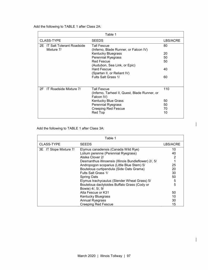
March 2020 | Illinois Tollway | 97
Add the following to TABLE 1 after Class 2A:
Add the following to TABLE 1 after Class 3A:
Table 1
CLASS-TYPE SEEDS LBS/ACRE
2E IT Salt Tolerant Roadside Mixture 7/
Tall Fescue (Inferno, Blade Runner, or Falcon IV) Kentucky Bluegrass Perennial Ryegrass Red Fescue (Audubon, Sea Link, or Epic) Hard Fescue (Spartan II, or Reliant IV) Fults Salt Grass 1/
80 20 50 50 40 60
2F IT Roadside Mixture 7/ Tall Fescue (Inferno, Tarheel II, Quest, Blade Runner, or Falcon IV) Kentucky Blue Grass Perennial Ryegrass Creeping Red Fescue Red Top
110 50 50 70 10
Table 1
CLASS-TYPE SEEDS LBS/ACRE
3E IT Slope Mixture 7/ Elymus canadensis (Canada Wild Rye) Lolium perenne (Perennial Ryegrass) Alsike Clover 2/ Desmanthus illinoensis (Illinois Bundleflower) 2/, 5/ Andropogon scoparius (Little Blue Stem) 5/ Bouteloua curtipendula (Side Oats Grama) Fults Salt Grass 1/ Spring Oats Elymus trachycaulus (Slender Wheat Grass) 5/ Bouteloua dactyloides Buffalo Grass (Cody or Bowie) 4/, 5/, 9/ Alta Fescue or K31 Kentucky Bluegrass Annual Ryegrass Creeping Red Fescue
10 40
2 1
25 20 30 50
5 5
50 10 30 15
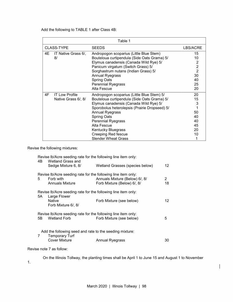
March 2020 | Illinois Tollway | 98
Add the following to TABLE 1 after Class 4B: Revise the following mixtures:
Revise lb/Acre seeding rate for the following line item only: 4B Wetland Grass and
Sedge Mixture 6, 8/ Wetland Grasses (species below) 12
Revise lb/Acre seeding rate for the following line item only: 5 Forb with Annuals Mixture (Below) 6/, 8/ 2
Annuals Mixture Forb Mixture (Below) 6/, 8/ 18
Revise lb/Acre seeding rate for the following line item only: 5A Large Flower
Native Forb Mixture (see below) 12 Forb Mixture 6/, 8/
Revise lb/Acre seeding rate for the following line item only: 5B Wetland Forb Forb Mixture (see below) 5
Add the following seed and rate to the seeding mixture:
7 Temporary Turf Cover Mixture Annual Ryegrass 30
Revise note 7 as follow: On the Illinois Tollway, the planting times shall be April 1 to June 15 and August 1 to November 1.
Table 1
CLASS-TYPE SEEDS LBS/ACRE
4E IT Native Grass 6/, 8/
Andropogon scoparius (Little Blue Stem) Bouteloua curtipendula (Side Oats Grama) 5/ Elymus canadensis (Canada Wild Rye) 5/ Panicum virgatum (Switch Grass) 5/ Sorghastrum nutans (Indian Grass) 5/ Annual Ryegrass Spring Oats Perennial Ryegrass Alta Fescue
15 10
2 2 2
30 40 25 20
4F IT Low Profile Native Grass 6/, 8/
Andropogon scoparius (Little Blue Stem) 5/ Bouteloua curtipendula (Side Oats Grama) 5/ Elymus canadensis (Canada Wild Rye) 5/ Sporobolus heterolepsis (Prairie Dropseed) 5/ Annual Ryegrass Spring Oats Perennial Ryegrass Alta Fescue Kentucky Bluegrass Creeping Red fescue Slender Wheat Grass
20 15
3 1
50 40 40 45 20 10
1
March 2020 | Illinois Tollway | 99
Add the following to end of the Article: The Contractor shall be responsible for the satisfactory growth of grass and stabilization of soils on all areas seeded under the Contract until final acceptance of the work. In the event that the length of time between the seeding and final acceptance is insufficient for the Engineer to ascertain that acceptable growth is established, final acceptance of the work will not be made until the following growing season, or until such time that the grass cover and soil stabilization can be appraised as satisfactory. The responsibility of the Contractor for satisfactory grass growth and soil stabilization shall thereafter be as provided in Article 109.08 (b). If the Contractor believes that the specified treatment will not produce substantial growth in any particular portion of the work, He/she shall arrange to test the soil. Based on the results of his soil tests, the Contractor shall then do whatever additional preparatory work he deems necessary to produce satisfactory growth before proceeding with seeding. Any such work not described in the Contract, but deemed by the Contractor to be necessary, shall be done by the Contractor at no additional cost to the Illinois Tollway, with the understanding that the Contractor is obligated under the Contract to produce satisfactory growth throughout the entire project. Washouts or gullies in seeded areas shall be repaired by spreading additional topsoil and the areas reseeded, fertilized, mulched, and covered with erosion control blanket by the Contractor at no additional cost to the Illinois Tollway at such time and in such manner as directed and approved by the Engineer. Reseeding of areas that have failed or have not produce satisfactory growth, shall, in such case, once again be accomplished in the same manner specified herein. The Contractor shall also remove any material dislocated by slides and restore any eroded areas to the original lines and slopes. Such preliminary restoration shall be subject to the Engineer’s approval before any reseeding or reapplication of erosion control material takes place. All such restoration shall be accomplished at no additional cost to the Illinois Tollway.
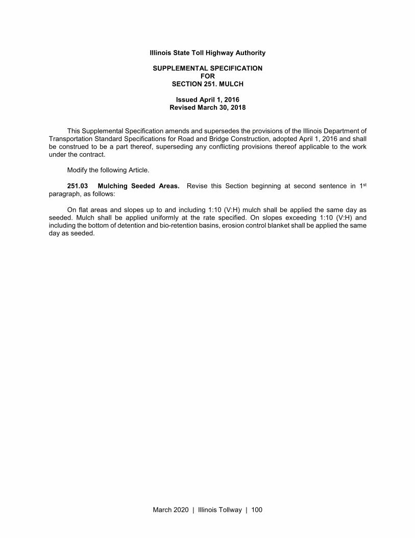
March 2020 | Illinois Tollway | 100
Illinois State Toll Highway Authority
SUPPLEMENTAL SPECIFICATION FOR
SECTION 251. MULCH
Issued April 1, 2016 Revised March 30, 2018
This Supplemental Specification amends and supersedes the provisions of the Illinois Department of Transportation Standard Specifications for Road and Bridge Construction, adopted April 1, 2016 and shall be construed to be a part thereof, superseding any conflicting provisions thereof applicable to the work under the contract.
Modify the following Article.
251.03 Mulching Seeded Areas. Revise this Section beginning at second sentence in 1st paragraph, as follows:
On flat areas and slopes up to and including 1:10 (V:H) mulch shall be applied the same day as seeded. Mulch shall be applied uniformly at the rate specified. On slopes exceeding 1:10 (V:H) and including the bottom of detention and bio-retention basins, erosion control blanket shall be applied the same day as seeded.
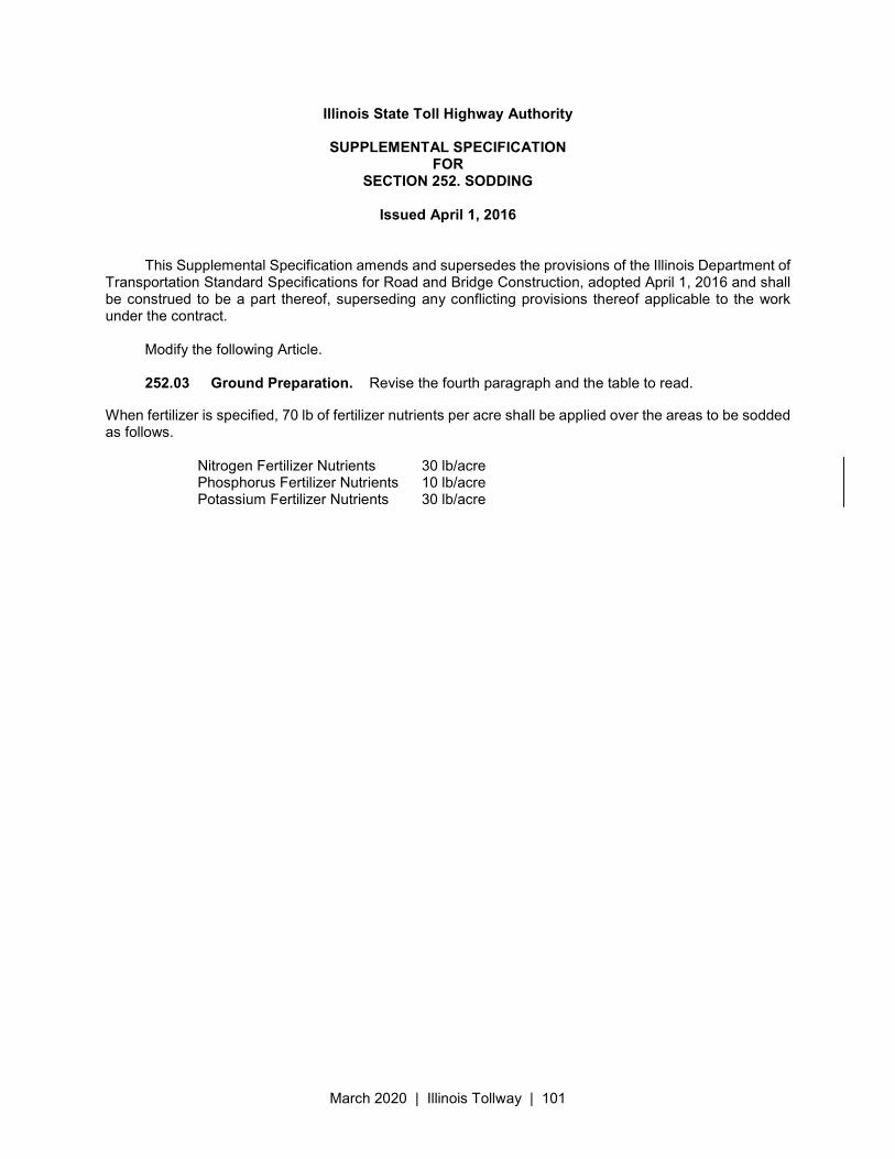
March 2020 | Illinois Tollway | 101
Illinois State Toll Highway Authority
SUPPLEMENTAL SPECIFICATION FOR
SECTION 252. SODDING
Issued April 1, 2016
This Supplemental Specification amends and supersedes the provisions of the Illinois Department of Transportation Standard Specifications for Road and Bridge Construction, adopted April 1, 2016 and shall be construed to be a part thereof, superseding any conflicting provisions thereof applicable to the work under the contract.
Modify the following Article.
252.03 Ground Preparation. Revise the fourth paragraph and the table to read.
When fertilizer is specified, 70 lb of fertilizer nutrients per acre shall be applied over the areas to be sodded as follows.
Nitrogen Fertilizer Nutrients 30 lb/acre Phosphorus Fertilizer Nutrients 10 lb/acre Potassium Fertilizer Nutrients 30 lb/acre
March 2020 | Illinois Tollway | 102
Illinois State Toll Highway Authority
SUPPLEMENTAL SPECIFICATION FOR
SECTION 253. PLANTING WOODY PLANTS
Issued April 1, 2016 This Supplemental Specification amends and supersedes the provisions of the Illinois Department of
Transportation Standard Specifications for Road and Bridge Construction, adopted April 1, 2016 and shall be construed to be a part thereof, superseding any conflicting provisions thereof applicable to the work under the contract.
Modify the following Articles:
253.14 Period of Establishment.
Revise the first paragraph, as follows:
Prior to final acceptance, the plants shall endure a period of establishment. This period will begin in June and end in September of the following year. A semi-final inspection will be held in September of the first year and a final inspection will be held in September of the last year. To qualify for semi-final inspection, all plants shall have been in place, in a live healthy condition on or before June 1st. To qualify for final inspection, plants shall have been in place for a minimum duration of one full year, and in a live healthy condition on or before June 1st. To qualify for acceptance, plants shall be in a live healthy condition, representative of their species, at the time of inspections.
Revise the first sentence of the second paragraph, as follows:
The inspections and acceptance of plant material shall not delay acceptance of the entire project and final payment due if the Contractor provides the Illinois Tollway with a surety bond in the full amount of all plant material items listed in the contract.
Revise the first sentence of the third paragraph, as follows:
The Illinois Tollway will assume the responsibility for all plant material found to be satisfactory at the time of inspection for successful completion of the period of establishment.
Revise the third sentence of the fourth paragraph, as follows:
All Plant material which dies within 30 days after being planted shall be replaced at that time and shall be considered as part of the original planting and be subject to the requirements of the period of establishment.
253.15(a) Revise the first paragraph, as follows:
During the period of establishment, additional watering shall be performed at least once within every
30 days during the months of May, September through December and at least once every 15 days during the months of June through August. The Engineer may direct the Contractor to adjust the watering rate and frequency depending upon weather conditions.
March 2020 | Illinois Tollway | 103
Illinois State Toll Highway Authority
SUPPLEMENTAL SPECIFICATION FOR
SECTION 280. TEMPORARY EROSION CONTROL
Issued April 1, 2016 Revised March 23, 2020
This Supplemental Specification amends and supersedes the provisions of the Illinois Department of Transportation Standard Specifications for Road and Bridge Construction, adopted April 1, 2016 and shall be construed to be a part thereof, superseding any conflicting provisions thereof applicable to the work under the contract.
Delete Section 280 in its entirety and replace with the following:
280.01 Description. This work shall consist of the erosion and sediment aspects of the project including, but not limited to, construction, maintenance and removal of various erosion and sediment control items, preparation of Erosion and Sediment Control Schedules, implementation and adherence to the approved Erosion and Sediment Control Schedules, management of the methods of earth disturbing operations, weekly co-inspections, and co-inspections following rainfalls.
Temporary erosion and sediment controls shall be installed prior to beginning any activities which will
potentially create erodible conditions. Erosion control and sediment controls for areas outside the limits of construction such as storage sites, plant sites, waste sites, haul roads, and Contractor furnished borrow sites shall be installed prior to beginning soil disturbing activities at each area. These offsite systems shall be designed by the Contractor and be subject to the approval of the Engineer.
The Contractor shall not commence any activities within a drainage area that disturbs soil or expose it to erosive forces until fully prepared to continuously pursue work until permanent soil stabilization is achieved. The installation of temporary soil erosion and sediment control Best Management Practices (BMPs) shall be performed in coordination with the installation of the permanent erosion control features to assure effective continuous erosion control throughout the life of the project. The Contractor will be required to construct, install and maintain all temporary and permanent erosion control features as grading advances.
The temporary erosion and sediment control systems shown on the Contract Plans represent the minimum systems anticipated for the project. Conditions created by the Contractor’s operations, or for the Contractor’s convenience, which are not covered by the Contract Plans, shall be provided as directed by the Engineer at no additional cost to the Illinois Tollway. Revisions or modifications of the erosion and sediment control systems shall have the Engineer’s written approval.
The Contractor shall be required to install and maintain all erosion and sediment control practices
and other protective measures identified in the Contract Plans and documents, as noted in these specifications, and/or as directed by the Engineer to provide effective and continuous erosion control protection throughout the full length of the Contract. Maintenance of erosion and sediment control devices and other BMPs for stormwater pollution prevention shall be maintained by the Contractor from the time of their installation until the end of their useful service life as approved by the Engineer. Approved new or replaced BMPs will be measured and paid for in accordance with the established Contract unit prices. Devices damaged due to the Contractor's negligence from failure to maintain BMPs shall be replaced at Contractor’s expense. Where inspections result in the determination that new or replacement BMPs are necessary, the BMPs shall be installed to ensure continuous effectiveness. When identified, BMPs shall be maintained, added, modified or replaced within the time period specified by the Engineer.
March 2020 | Illinois Tollway | 104
280.02 Management of Erosion and Sediment Control. This work shall consist of the management of erosion aspects of the project, including but not limited to, the cost of the Erosion and Sediment Control Manager, preparation of Erosion and Sediment Control Schedules, implementation and adherence to the approved Erosion and Sediment Control Schedules, management of the methods of earth disturbing operations, weekly co-inspections, co-inspections following precipitation events and maintenance not included in the various Pay Items. This work also includes repairs to installed erosion and sediment control items which were damaged by parties other than the Contractor, its subcontractors, or their agents or employees, and which the re-establishment of these items is not included elsewhere in this Section.
(1) Construction Requirement. This work is to be performed to ensure compliance with the Contract Plans and specifications; the latest editions of the Illinois Environmental Protection Agency "Illinois Urban Manual" and the National Pollutant Discharge Elimination System (NPDES) permit No. ILR10. The Contractor and its subcontractors will be required to sign the certification in the Stormwater Pollution Prevention Plan Special Provision prior to starting work.
(2) Penalties
(1) Non-Conformance/Failure to Respond: National Pollutant Discharge Elimination System (NPDES) / Erosion and Sediment Control Deficiency Deduction. When the Engineer is notified or determines an erosion and/or sediment control deficiency(s) exists, or the Contractor’s activities represents a violation of the Illinois Tollway’s NPDES permit, the Engineer will notify and direct the Contractor to correct the deficiency within a specified time. The specified time, which begins upon notification to the Contractor, will be from 1/2 hour to 1 week based on the urgency of the situation and the nature of the work effort required. The Engineer will be the sole judge.
A deficiency may be any discharge of sediment, lack of repair, maintenance, or implementation of erosion and/or sediment control devices included in the contract, or any failure to comply with the conditions of the Illinois Tollway’s NPDES permit. A deficiency may also be applied to situations where corrective action is not an option such as the failure to participate in a jobsite inspection of the project, failure to install required measures prior to initiating earth moving operations, disregard of concrete washout requirements, or another disregard of the NPDES permit.
If the Contractor fails to correct a deficiency within the specified time, a daily monetary deduction will be imposed for each calendar day or portion of a calendar day until the deficiency is corrected to the satisfaction of the Engineer. The calendar day(s) will begin with notification to the Contractor and end with the Engineer’s acceptance of the correction. The base value of the daily monetary deduction is $1000.00 and will be applied to each location for which a deficiency exists. The value of the deficiency deduction assessed for each infraction will be determined by multiplying the base value by a Gravity Adjustment Factor provided in Table A. For those deficiencies where corrective action was not an option, the monetary deduction will be immediate and will be valued at one calendar day multiplied by a Gravity Adjustment Factor.
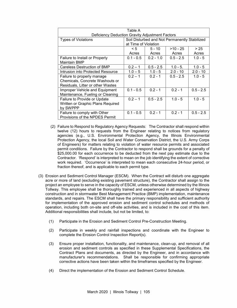
March 2020 | Illinois Tollway | 105
Table A Deficiency Deduction Gravity Adjustment Factors
Types of Violations Soil Disturbed and Not Permanently Stabilized at Time of Violation
< 5 Acres
5 - 10 Acres
>10 - 25 Acres
> 25 Acres
Failure to Install or Properly Maintain BMP
0.1 - 0.5 0.2 - 1.0 0.5 - 2.5 1.0 - 5
Careless Destruction of BMP 0.2 – 1 0.5 - 2.5 1.0 - 5. 1.0 - 5 Intrusion into Protected Resource 1.0 – 5 1.0 - 5 2.0 - 10 2.0 - 10 Failure to properly manage Chemicals, Concrete Washouts or Residuals, Litter or other Wastes
0.2 – 1 0.2 - 1 0.5 - 2.5 1.0 - 5
Improper Vehicle and Equipment Maintenance, Fueling or Cleaning
0.1 - 0.5 0.2 - 1 0.2 - 1 0.5 - 2.5
Failure to Provide or Update Written or Graphic Plans Required by SWPPP
0.2 – 1 0.5 - 2.5 1.0 - 5 1.0 - 5
Failure to comply with Other Provisions of the NPDES Permit
0.1 - 0.5 0.2 - 1 0.2 - 1 0.5 - 2.5
(2) Failure to Respond to Regulatory Agency Requests: The Contractor shall respond within twelve (12) hours to requests from the Engineer relating to notices from regulatory agencies (e.g., U.S. Environmental Protection Agency, the Illinois Environmental Protection Agency, the local Soil and Water Conservation District, the U.S. Army Corps of Engineers) for matters relating to violation of water resource permits and associated permit conditions. Failure by the Contractor to respond shall be grounds for a penalty of $25,000.00 for each occurrence to be deducted from the next pay estimate due to the Contractor. ‘Respond’ is interpreted to mean on the job identifying the extent of corrective work required. ‘Occurrence’ is interpreted to mean each consecutive 24-hour period, or fraction thereof, and is applicable to each permit type.
(3) Erosion and Sediment Control Manager (ESCM). When the Contract will disturb one aggregate acre or more of land (excluding existing pavement structure), the Contractor shall assign to the project an employee to serve in the capacity of ESCM, unless otherwise determined by the Illinois Tollway. This employee shall be thoroughly trained and experienced in all aspects of highway construction and in stormwater Best Management Practice (BMP) implementation, maintenance standards, and repairs. The ESCM shall have the primary responsibility and sufficient authority for implementation of the approved erosion and sediment control schedules and methods of operation, including both on-site and off-site activities, and is included in the cost of this item. Additional responsibilities shall include, but not be limited, to:
(1) Participate in the Erosion and Sediment Control Pre-Construction Meeting. (2) Participate in weekly and rainfall inspections and coordinate with the Engineer to
complete the Erosion Control Inspection Report(s). (3) Ensure proper installation, functionality, and maintenance, clean-up, and removal of all
erosion and sediment controls as specified in these Supplemental Specifications, the Contract Plans and documents, as directed by the Engineer, and in accordance with manufacturer's recommendations. Shall be responsible for confirming appropriate corrective actions have been taken within the timeframes specified by the Engineer.
(4) Direct the implementation of the Erosion and Sediment Control Schedule.
March 2020 | Illinois Tollway | 106
(5) Direct the implementation of pre-storm and winter shutdown procedures. (6) Coordinate the work of subcontractors and ensure the full execution of erosion and
sediment control measures for each operation and stage of work. (7) Coordinate with the Contractor’s Superintendent to ensure that all labor, material, and
equipment needed to install, maintain, and remove BMPs are available as needed. (8) Oversee the work of subcontractors and ensure the subcontractors undertake erosion
and sediment preventive measures at each stage of the work. (9) Coordinate with the Contractor’s Superintendent to implement necessary actions to
reduce anticipated or presently existing water quality or erosion problems resulting from construction activities.
(10) Attend construction meetings to discuss the erosion control schedule and inspections as
required. (11) Provide for erosion and sediment control methods for temporary work not shown on the
plans. (12) Ensure effective preventative BMPs are in place, recommend BMP changes for the
Engineer's approval, and coordinate with the Engineer to amend the SWPPP or Erosion and Sediment Control plan sheets to document changes.
At least 10 days prior to beginning any work on this project, the name and credentials of the ESCM shall be submitted to the Engineer for approval. Any changes in the ESCM shall require a resubmission of the above. The resubmission shall be timed to ensure that an ESCM is assigned to the project at all times.
(4) Schedule. Twenty-one days after the Notice of Award, the Contractor shall submit for approval to the Illinois Tollway, an Erosion and Sediment Control Schedule. The Erosion and Sediment Control Schedule shall be a graphical project schedule. The Contractor’s Progress Schedule may be used for this purpose if it includes the specified requirements. The schedule shall indicate how erosion and sediment control measures and other BMPs required by the NPDES permit and/or SWPPP will be implemented, sequentially phased with all items of the construction from mobilization to completion and acceptance of the work. The schedule shall specifically indicate the sequence of clearing and grubbing, earthwork operations, and construction of temporary and permanent BMPs. The schedule shall include BMPs for all areas within the project limits, including but not limited to, haul roads, borrow pits, and storage and other staging areas. The Erosion and Sediment Control Schedule shall contain an adequate level of detail with respect to all major work activities including, but not limited to, the following:
a. Clearing of areas necessary for installation of perimeter controls specified in the Contract Documents.
b. Construction of initial controls specified in the Contract Documents.
c. Mass clearing and grubbing.
d. Roadside clearing and grubbing.
e. Roadway and project area grading.
f. Excavations.
March 2020 | Illinois Tollway | 107
g. Paving, saw-cutting, and any other pavement-related operations.
h. Planned stockpiling operations.
i. Activities that may cause non-stormwater discharges, such as dewatering, grinding, etc.
j. Temporary and final stabilization activities staged over time for each area of the project.
k. Removal of perimeter controls.
The Erosion and Sediment Control Schedule shall show by location the dates for the deployment of the following:
a. Temporary soil stabilization BMPs.
b. Temporary sediment control BMPs.
c. Wind erosion control BMPs.
d. Tracking control BMPs.
e. Non-stormwater BMPs.
f. Waste management and materials pollution control BMPs.
Once the work has started, and during the construction period, the Contractor shall update the schedule for all BMPs on a regular basis, and as required to keep the SWPPP in compliance with the NPDES permit conditions and/or SWPPP.
(5) Pre-Construction Erosion and Sediment Control Meeting. At the pre-construction meeting, the Engineer will discuss with the Contractor the SWPPP and Erosion and Sediment Control Plan along with any special details or special provisions related to it, review the Contractor’s Erosion and Sediment Control Schedule, and emphasize the Illinois Tollway’s expectations and Contractor responsibilities. The discussions shall focus on ensuring that the Contractor will be able to implement the requirements of the SWPPP and Erosion and Sediment Control Plan as designed and identify/resolve any issues or concerns prior to any land disturbance. Subsequently, an Erosion and Sediment Control Field Meeting will be held prior to any soil disturbance to review field conditions and the Contractor’s planned construction sequence for any necessary adjustments to the Erosion and Sediment Control Plan.
(6) Inspection Meetings. Erosion and Sediment Control Inspection Meetings will be initiated and conducted by the Engineer, attended by the ESCM. The initial meeting will be held at least five days prior to the start of earth disturbing work and at least once every seven calendar days and within 24 hours of the end of a storm event which produces ½" or more precipitation or by the end of the following business or work day. An Erosion Control Inspection Report (A-38 Form) will be completed by the Engineer for each inspection. The Contractor’s ESCM shall review and return a signed copy of all inspection reports to the Engineer within 3 days following receipt.
280.03 Erosion and Sediment Control – Excavation. This work shall consist of the clearing, stripping, excavation and satisfactory disposal of all material, including rock, encountered in the construction of sediment basins, sediment traps, dewatering basins, temporary swales and temporary channel diversions in accordance with these Specifications and the storage volumes as shown on the Contract Plans or as directed by the Engineer.
March 2020 | Illinois Tollway | 108
EROSION AND SEDIMENT CONTROL - EXCAVATION shall not include excavation of ditches parallel to the roadway through cut sections or at the toe of slopes of embankments, or ditches at the top of cuts. Excavation for all such ditches shall be included in the payment for Earth Excavation, Section 202 of the Standard Specifications.
Excavation shall be carried on in such a manner that existing highway facilities, utilities, railroad tracks and other non-highway facilities which are to remain in place will not be damaged.
(a) Clearing and Striping. Before any sediment basin, sediment trap, dewatering basin, temporary swale, or temporary channel diversion is excavated for embankment, all trees, shrubs, roots and topsoil shall be removed from the area within the limits of the BMP site. Disposal of cleared materials shall be in accordance with Article 202.03 of the Standard Specifications, the Contract Plans and documents, and/or as directed by the Engineer.
Clearing and stripping and removal of topsoil will not be paid for separately but shall be considered as included in the payment for EROSION AND SEDIMENT CONTROL -EXCAVATION.
(b) Construction Requirements. The Contractor shall notify the Engineer at least three days in advance of the start of excavating operations to permit the completion of accurate measurements for volume determinations. Payment will not be made for any material excavated before such measurements have been taken.
All excavated material shall be used or disposed as specified in Article 202.03 of the Standard Specifications, the Contract Plans and documents, and/or as directed by the Engineer.
Upon completion of use of the basins, traps, swales, and diversions they shall be backfilled in accordance with the requirements of Section 205 of the Standard Specifications, the Contract Plans and documents, and/or as directed by the Engineer.
280.04 Erosion and Sediment Control – Cleanout. This work shall consist of excavation, removal and disposal of accumulated sediment, vegetation and debris from traps, basins, the area adjacent to silt fence, super silt fence, rectangular inlet protection, monofilament fabric inlet protection, ditch checks and any other clean out excavation, removal and disposal of accumulated sediment.
(a) Construction Requirements. Vegetation, sediment and minor debris build-ups shall be removed, and the capacity and performance of the control devices shall be re-established, in accordance with the criteria specified in these specifications, the Contract Plan and documents, and/or as directed by the Engineer.
Removed material shall be used or disposed as specified in Article 202.03 of the Standard Specifications, the Contract Plans and documents, and/or as directed by the Engineer.
280.05 Silt Fence. This work shall consist of the furnishing, installation, maintenance, removal and disposal of SILT FENCE used for the purpose of intercepting and slowing the flow of sediment-laden sheet flow from areas of disturbed soils.
The Contractor shall furnish, install, maintain, remove, and dispose all specified SILT FENCE in accordance with these Specifications, the Contract Plans and documents, and/or as directed by the Engineer.
(a) Materials. All materials shall conform to the applicable requirements of Materials, Division 1000 of the Standard Specifications and as modified or supplemented by the Illinois Tollway Supplemental Specifications:
Silt Fence Fabric ...................................................................... Article 1080.02
March 2020 | Illinois Tollway | 109
Support Posts: Support posts shall be a minimum of 48 inches long. Support posts shall be 2” x 2” nominal hardwood, 2" Schedule 40 steel pipe or steel support posts of a standard T or U section weighing not less than 1.33 pounds per lineal foot.
(b) Re-erect Silt Fence. This work shall consist of re-erecting SILT FENCE which has become ineffective as a result of natural causes. SILT FENCE damaged by the Contractor’s operations or negligence will not be re-erected under this item.
(c) Construction Requirements. Fence posts shall be driven a minimum of 24 inches into the ground and the maximum spacing between posts shall be 5 feet. The height of SILT FENCE shall be a minimum of 24 inches above the original ground surface.
The silt fence fabric shall be securely fastened to the upslope side of the wooden posts using heavy duty wire staples at least 1 inch long, or in accordance with manufacturer's recommendations. Fabric shall be attached to steel posts according to manufacturer’s recommendations. When splices are necessary, the fabric shall be spliced at a support post and posts twisted together. The SILT FENCE shall be entrenched a minimum depth of 8 inches, with an additional 6 inches extending along the bottom of the trench in the upslope direction. The posts shall be set, fabric installed, trench backfilled, and the soil compacted over the fabric to 95 percent. The SILT FENCE may also be entrenched by static slicing and installing the fabric to a minimum depth of 8 inches. SILT FENCE shall be installed with the ends turned upslope and “J-hooks” provided at the locations and dimensions specified in the plans and/or contract documents.
The Contractor shall exercise due care in the re-erecting of the SILT FENCE as not to damage otherwise reusable materials. Any material damaged in re-erecting shall be replaced by the Contractor at no additional expense to the Illinois Tollway. All of the requirements for the original installation of the SILT FENCE shall be adhered to when the fence is re-erected.
Sediment deposits shall be removed when the level of deposition reaches no greater than one-half the height of the SILT FENCE. Removed sediments shall be used or disposed as specified in Article 202.03 of the Standard Specifications, the Contract Plans and documents, and/or as directed by the Engineer.
All materials used to construct the SILT FENCE shall be removed when directed by the Engineer and shall become property of the Contractor and removed from the right of way.
The Contractor shall dress, to the existing grade, disturbed soils remaining in place after the SILT FENCE is removed, this includes topsoiling, fertilizing, and seeding the affected area in accordance with the Contract Plans and documents.
280.06 Temporary Swale. This work shall consist of the construction and maintenance of a temporary drainageway located to intercept and divert runoff to a stabilized outlet, to intercept sediment laden water and divert it to a sediment trapping device, or to divert flows from entering a disturbed area. The TEMPORARY SWALE shall be stabilized through the use of erosion resistant materials such as temporary ground cover and heavy-duty erosion control blanket (TREATMENT TYPE I), coarse aggregate CA 3 for ditch lining, 3 inches thick (TREATMENT TYPE II) or riprap gradation RR 3, 8 inches thick (TREATMENT TYPE III).
(a) Materials. All materials shall conform to the applicable requirements of Materials, Division 1000 of the Standard Specifications. Specific references are as follows:
Coarse Aggregate, CA 3 .......................................................Article 1004.01 Riprap, Gradation No. RR 3................................................ Article 1005.01 (c)
March 2020 | Illinois Tollway | 110
Filter Fabric ........................................................................ Article 1080.03 Heavy Duty Erosion Control Blanket ................................. Article 1081.10(c)
(b) Construction Requirements. Locations of the swale shall be as shown on the Contract Plans and/or as directed by the Engineer. The work will be performed in accordance with the applicable portions of the following sections of the Standard Specifications:
281 Riprap 282 Filter Fabric 251 Heavy Duty Erosion Control Blanket
And the following Articles of these specifications:
280.03 Erosion and Sediment Control – Excavation 280.15 Temporary Stabilization with Straw Mulch
Sediment deposits or debris in the swale shall be removed when deposition restricts flow capacity in the swale and/or as directed by the Engineer. Removed material shall be used or disposed as specified in Article 202.03 of the Standard Specifications, the Contract Plans and documents, and/or as directed by the Engineer.
280.07 Stabilized Construction Entrance. This work shall consist of the furnishing, installation, maintenance and removal of STABILIZED CONSTRUCTION ENTRANCE which is used to reduce or eliminate the tracking of sediment onto public rights-of-way or streets. The work also includes disposal of all materials used in the construction of the STABILIZED CONSTRUCTION ENTRANCE. Construction entrances shall be used in conjunction with the stabilization of construction roads and other exposed areas.
(a) Materials. All materials shall conform to the applicable requirements of Materials, Division 1000 of the Standard Specifications and as modified or supplemented by the Illinois Tollway Supplemental Specifications:
Coarse Aggregate, CA 3 .......................................................Article 1004.01 Filter Fabric ............................................................................Article 1080.03 Geocell: The cellular confinement system shall be a flexible web system such as Presto Products Companies GEOWEB GW30V8, or an approved equal. Corrugated Steel Pipe ...........................................................Article 1006.01
(b) Construction Requirements. The Contractor shall maintain continuous surveillance and shall continuously maintain, realign, or repair STABILIZED CONSTRUCTION ENTRANCE as shown on the Contract Plans and documents and/or as directed by the Engineer that are displaced or damaged by water, traffic, Contractor operations or any other cause. This may require periodic top dressing with additional aggregate as directed by the Engineer.
Topsoil shall be removed, corrugated steel pipe (PIPE CULVERT TEMPORARY) (if needed) and filter fabric placed, and the geocell installed and staked in accordance with the manufacturer’s recommendations. The geocell shall be filled with aggregate base course using CA 3 and methods and equipment recommended by the manufacturer.
The upper 4 inches of the entrance shall be constructed in accordance with the applicable requirements of Section 351 of the Standard Specifications using CA 3. When the STABILIZED CONSTRUCTION ENTRANCE is no longer required, all aggregate used in its construction shall be removed and used or disposed as specified in Article 202.03 of the Standard Specifications, the Contract Plans and documents, and/or as directed by the Engineer. All other materials used in its construction shall become the property of the Contractor and shall be removed from the right of way.
March 2020 | Illinois Tollway | 111
280.08 Silt Curtain. This work shall consist of the furnishing, installation and removal of a SILT CURTAIN, used for the purpose of temporarily controlling turbidity and debris encountered during construction in or adjacent to a waterway or waterbody.
The Contractor shall furnish, install, maintain, and remove the specified SILT CURTAIN in accordance with these Specifications, the Contract Plans and documents, and/or as directed by the Engineer.
(a) Materials. The Flotation Boom shall be a commercially available, pre-assembled system, including a geo-synthetic barrier/curtain section, flotation and anchoring system, ballast chain, and mooring system. The manufacturer must supply a certification that the product supplied meets the requirements of this specification. All materials shall conform to the applicable requirements of Materials, Division 1000 of the Standard Specifications and specific references as follows:
Fabric: The fabric must be Non-Woven Polypropylene and have the following properties:
Requirement Test Method Value Minimum Grab Tensile Strength ASTM D4632 200 lb Minimum Ultraviolet Stability ASTM D4355 70% All numerical values represent minimum average roll values. Average test results from all rolls in a lot must conform the tabulated values.
Flotation. Flotation material must be an expanded polystyrene or closed cell solid foam material which has sufficient buoyancy to provide the curtain with continuous support, and a minimum of 6 inches freeboard. Ballast Chain: Ballast must be minimum 5/16 in. galvanized steel chain and shall weight at least 1.1 lb/ft. Anchor Lines. Anchor lines must be minimum 1/2 in. nylon or polypropylene rope. Anchors: Anchors must have a sufficient mass and spaced/located to secure the barrier as recommended by the manufacturer depending on current flow velocities. Mooring Buoys. Mooring buoys must have provisions for the mooring line to be securely attached and be sufficiently buoyant to remain afloat under normal load conditions, if needed. Additional properties shall meet manufacturer's recommendations for the application.
(b) Construction Requirements. The SILT CURTAIN shall be installed at the location(s) as shown on the Contract Plans and/or as directed by the Engineer. The boom shall be installed in such a manner as to prevent drift shoreward or downstream. The curtain height shall provide sufficient slack to allow the top of the curtain to rise to the maximum expected high-water level (including waves) while the bottom maintains continuous contact with the bottom of the waterway or waterbody except where significant wind or wave action is present. Where significant wind and/or wave action (over 1 foot) is present for the majority of the duration of the project, the depth of the SILT CURTAIN shall be 1 foot above the bottom at the mean low water level to prevent disturbing existing sediment on the bottom of the water body with the movement of the lower end of the SILT CURTAIN. Additionally, the maximum depth of the SILT CURTAIN where significant wind and/or wave action is present shall be 12 feet below the surface, regardless of the depth of the water body.
March 2020 | Illinois Tollway | 112
Anchors shall be installed per the manufacturer's recommendations on both the shore and stream side to maximize stability. Shore anchors shall consist of a post with dead man or approved equal. Stream anchors if needed shall be of sufficient size, type and strength to stabilize the boom with the number and spacing dependent on the flow velocities in the waterway. Anchors shall be buoyed to prevent the boom from being pulled under water if needed. Within navigable waters, the silt curtain and anchors shall be clearly marked with crown buoys as they pose an obstacle to navigation. Under no circumstances shall the SILT CURTAIN be installed across a body of water.
The Contractor shall be responsible for maintenance of the SILT CURTAIN for the full length of the Contract. Maintenance shall consist of actions to prevent damage to the device and repair of the device where damaged by any cause. If the curtain will be in place through the winter, care must be taken to prevent ice damage.
On completion of the project, the Contractor shall remove the boom in a manner that will prevent siltation of the waterway. The SILT CURTAIN shall not be removed until the water behind the barrier has equal or greater clarity than the waterway or waterbody. The SILT CURTAIN and related components shall become the property of the Contractor and shall be removed from the right of way.
280.09 Temporary Stream Crossing. This work shall consist of furnishing, placing and removing filter fabric, temporary culvert and riprap, excavating the bottom to the required depth, and the disposal of excavated materials to provide a crossing across a stream or watercourse for short-term use by construction equipment and traffic. The location of TEMPORARY STREAM CROSSINGS shall be as indicated on the Contract Plans and/or as directed by the Engineer. This work also includes proper disposal of all materials used in construction of the TEMPORARY STREAM CROSSING and when the stream has base flow, this work also includes the installation of temporary corrugated metal pipe(s) at the stream invert.
(a) Materials. All materials shall conform to the applicable requirements of Materials, Division 1000 of the Standard Specifications. Specific references are as follows:
Filter Fabric ............................................................................Article 1080.03 Riprap Gradation No. RR 3 ...................................................Article 1005.01(c) Corrugated Steel Pipe ....................................................... Article 1006.01
(b) Construction Requirements. The work will be performed in accordance with the applicable portions of the following Article of these specifications:
280.14 Temporary Riprap
Unless otherwise specified, the Contractor shall furnish to the Engineer, in writing, a plan for installing and removing the TEMPORARY STREAM CROSSING. Acceptance of this plan will not relieve the Contractor of responsibility for completing the work as specified.
The TEMPORARY STREAM CROSSING shall be excavated to the depth and limits shown on the Contract Plans for placement of the riprap. Excavated material shall be used or disposed in accordance with Article 202.03 of the Standard Specifications, the Contract Plans and documents, and/or as directed by the Engineer.
When indicated on the Contract Plans and documents, filter fabric and corrugated steel pipe (PIPE CULVERT TEMPORARY) shall be placed in the excavated bottom, beneath the riprap, to the lines and dimensions shown in the Contract Plans and/or as directed by the Engineer.
The riprap shall be placed to the lines and dimensions shown in the Plans. Methods and equipment used for placing the riprap shall be approved by the Engineer.
March 2020 | Illinois Tollway | 113
The Contractor shall construct and maintain continuous surveillance and shall continuously maintain, realign, repair or replace all TEMPORARY STREAM CROSSINGS shown on the Contract Plans and/or as directed by the Engineer, that are displaced or damaged by wind, water, traffic, Contractor operations or any other cause. Maintenance of the TEMPORARY STREAM CROSSING shall be for the full length of the contract. Maintenance of the crossing may require periodic top dressing with additional riprap. Accumulated sediment or other blockages shall be removed as needed to maintain the functionality of the crossing.
Upon completion of the work requiring the use of the TEMPORARY STREAM CROSSING, the crossing shall immediately be removed and the stream channel returned to its original cross section or cross section as specified on the Contract Plans and disturbed areas stabilized as specified. The riprap used in construction of the TEMPORARY STREAM CROSSING shall be used or disposed as specified in Article 202.03 of the Standard Specifications, the Contract Plans and documents, and/or as directed by the Engineer. All other material shall become the property of the Contractor and shall be removed from the right of way.
280.10 Super Silt Fence. This work shall consist of the furnishing, installation, maintenance, removal, and disposal of SUPER SILT FENCE used for intercepting and slowing the flow of sediment-laden sheet flow from areas of disturbed soils. This design consists of geotextile fabric attached to and reinforced by chain link fence. The fence backing gives the fence increased strength to resist the weight of soil and water which may be trapped by the fence in a large drainage area and to provide an additional level of protection to sensitive environmental resources.
The Contractor shall furnish, install, maintain, remove, and dispose all specified SUPER SILT FENCE in accordance with these Specifications, the Contract Plans and documents, and/or as directed by the Engineer.
(a) Materials. All materials shall conform to the applicable requirements of Materials, Division 1000 of the Standard Specifications. Specific references are as follows:
Fencing .............................................................................. Article 1006.27 Silt Fence Fabric................................................................. Article 1080.02
(b) Construction Requirements. The SUPER SILT FENCE shall be erected at the location shown on the Contract Plans or on a line established by the Engineer. The chain link fencing shall be constructed in accordance with Section 664 of the Standard Specifications except that the fabric shall be embedded as shown on the Contract Plans and the concrete footing shall not be used. Posts shall be anchored with drive anchor assemblies meeting the approval of the Engineer. Grounding of the fence will not be required.
All posts shall be installed/driven so that at least 36 inches of the post will protrude above the ground. The chain link wire and geotextile shall be stretched taut and securely fastened to the posts as shown on the Contract Plans. The edge of the fence and geotextile shall be buried at least eight inches below ground surface to prevent undermining. When splicing of the geotextile is necessary, the fabric shall be overlapped approximately 18 inches.
Sediment deposits shall be removed when the level of deposition reaches no greater than one-half the height of the SUPER SILT FENCE. Removed sediments shall be used or disposed as specified in Article 202.03 of the Standard Specifications, the Contract Plans and documents, and/or as directed by the Engineer.
The Contractor shall dress, to the existing grade, sediment deposits remaining in place after the SUPER SILT FENCE is no longer required, this includes topsoiling, fertilizing, and seeding the affected area in accordance with the Contract Plans and documents.
March 2020 | Illinois Tollway | 114
All material used to construct the SUPER SILT FENCE shall become the property of the Contractor and shall be removed from the right of way.
280.11 Temporary Pipe Slope Drain. This work shall consist of the furnishing and installation of pipe, anchor devices, geotextile fabric and flared end sections to convey surface runoff down the face of unstabilized slopes to minimize erosion on the slope face. A TEMPORARY PIPE SLOPE DRAIN is always used in conjunction with earth dikes (berms) that direct the runoff to the temporary pipe slope drain flared end section.
The Contractor shall furnish, install, maintain, and remove all specified TEMPORARY PIPE SLOPE DRAINS in accordance with these Specifications, the Contract Plans and documents, and/or as directed by the Engineer.
(a) Materials. All materials shall conform to the applicable requirements of Materials, Division 1000 of the Standard Specifications and as modified or supplemented by the Illinois Tollway Supplemental Specifications:
Polyethylene Pipe ..................................................................Article 1040.04 Corrugated Steel Pipe ...........................................................Article 1006.01 Flexible Polyethylene Tubing ................................................ASTM F667 Heavy Duty Erosion Control Blanket .....................................Article 1081.10(c) Wire Staples ....................................................................... Article 1081.10(d)
(b) Flared End Section. The flared end section shall be of the same material and size used for the temporary pipe slope drain.
(c) Construction Requirements. The TEMPORARY PIPE SLOPE DRAIN may be constructed using any of the materials specified above and shall outlet into a sediment trap or basin, or a stable conveyance system that leads to a trap or basin. The TEMPORARY PIPE SLOPE DRAIN shall be securely anchored to the slope using procedures recommended by the manufacturer. All connections are to be watertight. A flared end section shall be attached to the inlet end of the pipe and shall be relocated each time the pipe is extended. The height of the earth dike at the location of the TEMPORARY PIPE SLOPE DRAIN shall be at least 2 times the diameter of the pipe. To prevent erosion around the flared end section, Heavy Duty Erosion Control Blanket will be placed around the flared end section and shall extend 5 feet in front of it and up the front face of the dike.
At the end of each construction day, temporary dikes (berms) along the edges of the top of the embankment shall be constructed and each TEMPORARY PIPE SLOPE DRAIN will be extended, and the inlet reinstalled.
The TEMPORARY PIPE SLOPE DRAINS shall be operated and maintained by the Contractor for the full length of the contract to perform their intended function until the slopes are protected with permanent erosion control measures or otherwise directed by the Engineer. When the TEMPORARY PIPE SLOPE DRAIN is no longer required, the Contractor shall remove all materials used in its construction and restore the areas by establishing vegetative cover as specified in the Contract Plans and documents. All materials shall become the property of the Contractor and shall be removed from the right of way.
280.12 Tree Protection. Temporary fencing shall be erected and maintained around trees designated on the Contract Plans and/or as directed by the Engineer to reduce the damage to and loss of trees during construction.
March 2020 | Illinois Tollway | 115
The Contractor shall furnish, install, maintain, and remove all specified TREE PROTECTION in accordance with these Specifications, the Contract Plans and documents, and/or as directed by the Engineer.
(a) Materials. All materials shall conform to the applicable requirements of Materials, Division 1000 of the Standard Specifications and as modified or supplemented by the Illinois Tollway Supplemental Specifications:
Fence Stakes ..................................................................... Article 1081.15(b) Fence ................................................................................. Article 1081.15(d) The temporary fence shall be similar to plastic or wood lath snow fence and shall be a minimum of 4 feet in height.
(b) Construction Requirements. TREE PROTECTION shall be constructed at the locations shown in the Contract Plans and/or as directed by the Engineer. Support post spacing shall not exceed 5 feet.
On completion of the project, all materials shall become the property of the Contractor and shall be removed from the right of way.
280.13 Temporary Channel Diversion. This work shall consist of excavating, stabilizing, maintaining and operating the TEMPORARY CHANNEL DIVERSION needed to carry the existing stream flow through or around a construction site to isolate construction activities from contact with stream flow while the permanent drainage structure is being installed.
The Contractor shall excavate, stabilize, maintain and operate all specified TEMPORARY CHANNEL DIVERSIONS in accordance with these Specifications, the Contract Plans and documents, and/or as directed by the Engineer.
(a) Materials. All materials shall conform to the applicable requirements of Materials, Division 1000 of the Standard Specifications and as modified or supplemented by the Illinois Tollway Supplemental Specifications:
Geotextile Fabric ....................................................................Article 1080.02 Fabric shall be a non-woven geotextile meeting the requirements of the above article. Riprap Gradation No. RR 3 ...................................................Article 1005.01(c)
(b) Construction Requirements. The work will be performed in accordance with the applicable portions of the following sections of the Standard Specifications:
281 Riprap
And the following Article of these specifications:
280.03 Erosion and Sediment Control – Excavation
The installation of a TEMPORARY CHANNEL DIVERSION shall be done in a sequence to assure protection of the water quality of existing streams. Excavation of the diversion channel shall be performed with plugs at both ends of the diversion channel to avoid stream flow from entering the diversion channel prematurely. The plugs may be constructed of rip-rap, sandbags, sheet piling, or the existing undisturbed soil. The excavation and stabilization of the TEMPORARY STREAM DIVERSION CHANNEL shall be a continuous process with the stabilization occurring immediately after the excavation of an area. When fabric is used for or as part of the lining of the TEMPORARY STREAM DIVERSION CHANNEL, the fabric shall be wide enough to span from bank to bank so that any seams will be perpendicular to the diversion channel flow. When seams parallel to the
March 2020 | Illinois Tollway | 116
flow direction are necessary, they shall be pre-sewn, or field sewn following manufacturer’s specifications. Sections of fabric shall be shingled with the upstream sections of fabric overlapping the downstream sections of fabric a minimum of 36 inches. The fabric shall be secured per the manufacturer’s specifications. The fabric shall lay flat on the channel and be in direct contact with the soil without any void spaces. Sharp objects shall be removed to avoid puncturing the fabric. Prior to diverting stream flow, the Contractor shall ensure the fabric is properly secured at the upstream end of the temporary channel, as well as all along the channel. Water shall not be diverted through the diversion channel until it is adequately protected with geotextile. Once the TEMPORARY STREAM DIVERSION CHANNEL has been completely excavated and stabilized and ready to receive stream flow, the downstream plug shall be removed first, followed by removal of the upstream plug.
Unless otherwise specified, the Contractor shall furnish to the Engineer, in writing, a plan for diverting stream flows before beginning the construction work for which the TEMPORARY STREAM CHANNEL DIVERSION is required. Acceptance of this plan will not relieve the Contractor of responsibility for completing the work as specified.
The Contractor shall construct and maintain continuous surveillance and shall continuously maintain, repair, or replace the TEMPORARY CHANNEL DIVERSION as specified on the Contract Plans and documents, and/or as directed by the Engineer that are damaged by any cause. The maintenance shall be for the full length of the contract to prevent erosion or failure of the non-erodible plugs, channel banks and lining, to remove sediment accumulations or other blockages to maintain the designed carrying capacity, or other maintenance necessary to maintain function of the diversion.
The TEMPORARY CHANNEL DIVERSION shall be removed/backfilled as specified in the Contract Plans and documents and/or as directed by the Engineer once the permanent drainage structure is in place and stabilized.
280.14 Temporary Riprap. This work shall consist of placing filter fabric and a protective coating of dumped or hand-laid stone or broken concrete riprap for rock check dams, stone outlet structure sediment traps, dewatering basins, temporary channel diversions, temporary swales, diversion dikes, temporary stream crossings, culvert inlet protection stone, sediment basin aggregate berms and aggregate berms as shown on the Contract Plans and/or as directed by the Engineer, and the removal of the riprap and filter fabric upon the completion of its need. Filter fabric shall be installed under all riprap or aggregate and is incidental to the work.
(a) Materials. All materials shall conform to the applicable requirements of Materials, Division 1000 of the Standard Specifications. Specific references are as follows:
Filter Fabric ............................................................................Article 1080.03
Riprap Gradation No. RR 3 ................................................ Article 1005.01(c)
(b) Construction Requirements. The work will be performed in accordance with the applicable portions of the following sections of the Standard Specifications:
281 Riprap
And the following Article of these specifications:
280.03 Erosion and Sediment Control – Excavation
Prior to placing TEMPORARY RIPRAP, all surfaces to be protected shall be graded and finished so as to be stable and firm. Prepared surfaces that become crusted shall be reworked to an acceptable condition before placing the fabric. Prior to the installation of the fabric, the surface
March 2020 | Illinois Tollway | 117
shall be cleared of debris, sharp objects, and trees. Tree stumps shall be cut to the level of the prepared ground surface. If stumps cannot be cut to the ground level, they shall be completely removed. All wheel tracks, ruts, or surface irregularities in excess of 2 inches in depth shall be graded smooth or otherwise filled with soil to provide a reasonably smooth surface. The filter fabric shall not be placed until the preparation has been approved by the Engineer. At the time of placement, the fabric shall be free of defects, deterioration, and damage. Fabric damaged during its installation or during placement of riprap shall be replaced or repaired. Repairs shall be made by removing the material around the damage and covering it with a patch of fabric using an overlap of 4 feet in each direction. The patch shall be held in position with securing pins. Fabric of insufficient width or length to fully cover the specified area shall be lapped. Successive lengths of fabric shall be overlapped at least 3 feet, with the upstream length on top. Pin the overlap by placing 3 pins evenly spaced across the end of each of the overlapping lengths and by placing 3 pins across the width of the center of overlap area. An anchor slot shall be placed at the upslope and downslope ends of the fabric placement. Check slots shall be constructed by placing a tight fold at least 8 inches vertically into the soil. Check slots shall be spaced so that a check slot occurs within each 25 feet. Pin the fabric in the check slot at each edge overlap and in the center of the fabric. The soil shall be firmly tamped against the fabric in the slot. Fabric shall be applied with the length of roll laid parallel to the flow of the water. When installed in a ditch, start the installation with the initial strip placed in the center of the ditch to avoid an overlap in the center of the ditch. Where more than one width is required, lap joints to be limited to one every nine feet of width. Securing Pins shall be 3/16" x 18" long wire with a 1-½” washer attached and shall be driven flush with fabric surface. The pins shall be installed in accordance with the manufacturer’s recommendations. Additional pins, regardless of the location, shall be installed as necessary to prevent any slippage of the filter fabric.
All TEMPORARY RIPRAP shall be used or disposed as specified in Article 202.03 of the Standard Specifications, the Contract Plans and documents, and/or as directed by the Engineer. Filter fabric shall become property of the Contractor and removed from the right of way.
280.15 Temporary Stabilization with Straw Mulch. This work shall consist of preparing seed beds, sowing temporary seed mixture; along with furnishing, transporting and placing mulch on areas that cannot, at the time, be stabilized with permanent vegetative measures. This work includes placing both straw and wood fiber mulch over the temporary seeded area. The Engineer may require that critical locations be seeded immediately, and the Contractor shall seed in the specified areas within 48 hours of such directive. At some future date, areas where Temporary Stabilization with Straw Mulch will be treated as needed to establish the permanent vegetative cover, including mowing, removal of temporary vegetation, disking and/or other methods required to prepare the area for permanent vegetation will be included in this work.
(a) Materials. All materials shall conform to the applicable requirements of Materials, Division 1000 of the Standard Specifications and as modified or supplemented by the Illinois Tollway Supplemental Specifications:
Grass Seeds ...................................................................... Article 1081.04 Fertilizer .............................................................................. Article 1081.08 Straw Mulch ....................................................................... Article 1081.06(a)(1) Hydraulic Mulch………………………………………………...Article 1081.06(a)(2)
Seed for spring and summer planting shall be annual rye grass applied at a rate of 50 lbs/acre combined with white or red sweet clover applied at a rate of 15 lbs/acre.
March 2020 | Illinois Tollway | 118
Seed for fall planting shall be Hard Red Winter Wheat and Winter Rye (grain) mixed in equal proportions and applied at the rate of 100 lbs/acre.
Fertilizer nutrients shall be applied at the rates of 30 lbs/acre of Nitrogen and 90 lbs/acre of potassium for newly seeded areas. Straw mulch shall be stalks of wheat, rye, oats or other approved straw that is air dried.
Replace the first sentence of Article 1081.06(a)(2) of the Standard Specifications with the following:
Hydraulic mulch may be applied to temporary seeded areas only. Hydraulic mulch shall be a bonded fiber matrix of virgin or recycled defibrated wood cellulose fiber and cross-linked insoluble hydro-colloidal tackifiers containing no growth or germination inhibiting factors. Hydraulic mulch containing paper fibers shall not be allowed.
(b) Construction Requirements. Seed bed preparation shall consist of light disking if the soil is hard packed or caked. Erosion rills greater than 1 inch in depth shall be filled and blended with the surrounding soil. Seed bed preparation shall not be required if the surface is uniformly smooth and in a loose condition.
Within 24 hours after the seed is applied using a Hydroseeder, the seeded area shall be given a covering of mulch as follows:
(1) The mulch blower shall apply straw mulch at the rate of 4000 lbs. per acre, or per manufacturer recommendations. The mulch shall be loose enough to permit air to circulate but compact enough to reduce erosion.
(2) The straw mulch is to be thoroughly stabilized by following the straw application immediately with an overspray application of wood fiber mulch applied as a slurry of 750 lbs of mulch and 1000 gallons of water per acre by an approved hydraulic mulch applicator. The hydraulic mulch slurry shall be agitated a minimum of 5 minutes before application and shall be agitated during application. Hydraulic mulch shall not be applied when the ambient temperature is at or below freezing. To achieve full and even coverage, the hydraulic mulch shall be applied from two opposing directions.
Following the mulching operation, foot and vehicular traffic, or the movement of equipment over the mulched area shall be restricted. Any damaged areas will be repaired and replaced at the Contractor’s expense.
(c) Same-Day Stabilization. This work shall consist of the operations necessary for the continuous or expedited application of stabilization materials to disturbed areas. Same-day stabilization is used to minimize erosion and the movement of soils at those areas shown on the Contract Plans or as directed by the CM to stabilize erosive prone areas or critical disturbed areas where there is a risk that sediment laden runoff may enter sensitive environmental areas.
Where shown on the Contract Plans, SAME-DAY STABILIZATION shall be utilized to reduce the movement of soils once they are exposed by the Contractor’s operations as directed by the Engineer. SAME-DAY STABILIZATION is to be implemented after the initial perimeter controls are in place and concurrently with the Contractor’s daily operations. In this case, the work zone must be left in such condition that the grading areas, disturbed that day, are stabilized and measures are in place to control sediment stormwater runoff to the satisfaction of the Engineer. The Contractor shall be responsible for coordinating his operations with the work of any sub-contractors, to ensure that stabilization is performed the same day that the disturbance occurs.
March 2020 | Illinois Tollway | 119
The Engineer may also direct the Contractor to provide SAME-DAY STABILIZATION to critical disturbed areas where there is a risk of sediment laden runoff occurring. When directed by the Engineer, SAME-DAY STABILIZATION shall be placed at the locations specified by the Engineer and once the Contractor’s activities are completed for the work day.
SAME-DAY STABILIZATION may consist of either temporary erosion control measures or the permanent landscaping indicated on the Contract Plans. The permanent landscaping shall be implemented as the SAME-DAY STABILIZATION whenever possible. This means that the Contractor must stage his work so that portions of the slopes and ditches can be brought to finish grade, topsoiled and landscaped prior to the end of the workday.
When permanent landscaping is not possible, due either to construction staging or specification constraints, SAME-DAY STABILIZATION shall consist of temporary erosion control measures. The primary method of SAME-DAY STABILIZATION during grading operations shall be Article 280.15 TEMPORARY STABILIZATION WITH STRAW MULCH. Other temporary methods shall be as specified in the Contract Plans and documents and/or directed by the Engineer.
The performance of SAME-DAY STABILIZATION is subject to the penalties for non-conformance and failure to respond as outlined in Article 280.02 of these Supplemental Specifications.
280.16 Diversion Dike. This work shall consist of the construction and maintenance of a temporary ridge of compacted soil, located to intercept and divert runoff to a stabilized outlet or to intercept sediment laden water and divert it to a sediment trapping device. The DIVERSION DIKE shall be stabilized through the use of erosion resistant materials such as temporary ground cover and heavy-duty erosion control blanket (TREATMENT TYPE I), coarse aggregate CA 3 for ditch lining, 3 inches thick (TREATMENT TYPE II) or riprap gradation RR 3, 8 inches thick (TREATMENT TYPE III).
(a) Materials. All materials shall conform to the applicable requirements of Materials, Division 1000 of the Standard Specifications. Specific references are as follows:
Coarse Aggregate, CA 3 .................................................... Article 1004.01 Riprap, Gradation, No. RR 3............................................... Article 1005.01(c) Filter Fabric ........................................................................ Article 1080.03 Heavy Duty Erosion Control Blanket ................................. Article 1081.10(c)
(b) Construction Requirements. Locations of the DIVERSION DIKE shall be as shown on the Contract Plans and/or as directed by the Engineer. The work will be performed in accordance with the details in the Contract Plans and applicable portions of the following sections of the Standard Specifications:
281 ................................................. Riprap 282 .............................................. Filter Fabric 251................................................. Heavy Duty Erosion Control Blanket
And the following Article of these specifications:
280.15 Temporary Stabilization with Straw Mulch The type of stabilization to be used shall be shown on the Contract Plans. The embankment used to construct the dike shall be placed along an alignment that has had all trees, brush, stumps and other obstructions removed that would interfere with the proper functioning of the earth dike berm and flow channel. The fill shall be compacted by methods and equipment approved by the Engineer.
March 2020 | Illinois Tollway | 120
All of the aggregate and riprap used in construction of the DIVERSION DIKE shall be used or disposed as specified in Article 202.03 of the Standard Specifications, the Contract Plans and documents, and/or as directed by the Engineer. All other materials shall become the property of the Contractor and shall be removed from the right of way.
280.17 Dewatering Basins. A DEWATERING BASIN shall be installed wherever the Contractor is removing and discharging water from excavated areas on the construction site and the water is not being routed through an adequately sized sediment trap or sediment basin. The purpose of the basin is to temporarily store the discharged water and to release it in a manner that causes the sediment laden water to be filtered prior to release into a natural drainageway or stabilized conveyance.
(a) Materials. All materials shall conform to the applicable requirements of Materials, Division 1000 of the Standard Specifications. Specific references are as follows:
Filter Fabric ........................................................................ Article 1080.03 Riprap Gradation No. RR 3 ................................................ Article 1005.01(c)
(b) Construction Requirements. The work will be performed in accordance with the applicable portions of the following Articles of these specifications:
280.03 Erosion and Sediment Control – Excavation 280.14 Temporary Riprap
The volume required to be stored is dependent upon the pumping rate and frequency, the soil type being dewatered, and the amount of sediment in the water. The working volume of the DEWATERING BASIN must have sufficient volume to provide for a minimum hydraulic retention time under peak instantaneous flow conditions to meet discharge requirements. The minimum size of a DEWATERING BASIN shall be 10’x10’x3' of depth. The location of all Dewatering Basins shall be approved by the Engineer.
The Contractor shall be responsible for maintenance of the DEWATERING BASIN for the full length of the Contract. Sediment deposits shall be removed when the level of deposition reaches no greater than 50 percent of the DEWATERING BASIN capacity.
All riprap used in construction of the DEWATERING BASIN and removed sediment deposits shall be used or disposed as specified in Article 202.03 of the Standard Specifications, the Contract Plans and documents, and/or as directed by the Engineer. All other materials shall become the property of the Contractor and shall be removed from the right of way.
280.18 Rectangular Inlet Protection. This work shall consist of the furnishing, installation, maintenance and removal of a wooden frame with chain link fence supported monofilament fabric (or) a rigid polyethylene frame with a fitted geotextile filter, to protect existing and new inlets, catch basins and manholes with open lids, where shown on the Contract Plans and/or as directed by the Engineer.
(a) Materials. All materials shall conform to the applicable requirements of Materials, Division 1000 of the Standard Specifications and as modified or supplemented by the Illinois Tollway Supplemental Specifications:
Chain Link Fence................................................................ Article 1006.27 Monofilament Fabric: Fabric shall be a woven monofilament geotextile meeting the requirements specified in Illinois Urban Manual Material Specification Code 592, Table 1, Class IV. Frame and Fitted Geotextile Filter ..................................... Article 1081.15(j) (1) and (2)
March 2020 | Illinois Tollway | 121
(b) Construction Requirements. The RECTANGULAR INLET PROTECTION shall be constructed as shown on the Contract Plans. At the Contractor's option, the 2’ x 4’ wood frame can be substituted using 2½” Galvanized or Aluminum Posts installed as specified for Super Silt Fence. The polyethylene frame and fitted geotextile filter assembly shall be installed in accordance with the Manufacturer’s written installation instructions.
The RECTANGULAR INLET PROTECTION shall be cleaned, or removed and replaced, as sediment accumulates, the filter becomes dogged, and/or performance Is compromised. Where there Is evidence of sediment accumulation adjacent to the Inlet protection measure, the deposited sediment shall be removed by the end of the same business day in which it is found or by the end of the following business day if removal by the same business day is not feasible. When no longer required, the RECTANGULAR INLET PROTECTION shall be removed, and all materials used in its construction shall become the property of the Contractor and shall be removed from the right of way.
280.19 Geotextile Fabric, Class C. This work shall consist of the furnishing, installation and removal of geotextile fabric used to line temporary channel diversions.
(a) Materials. All materials shall conform to the applicable requirements of Materials, Division 1000 of the Standard Specifications. Specific references are as follows:
Geotextile Fabric ................................................................ Article 1080.02
(b) Constructions Requirements. All surfaces to be protected shall be graded and finished so as to be stable and firm. Prepared surfaces that become crusted shall be reworked to an acceptable con-dition before placing the fabric. Prior to the installation of the fabric, the surface shall be cleared of debris, sharp objects, and trees. Tree stumps shall be cut to the level of the prepared ground surface. If stumps cannot be cut to the ground level, they shall be completely removed. All wheel tracks, ruts, or surface irregularities in excess of 2 inches in depth shall be graded smooth or otherwise filled with soil to provide a reasonably smooth surface. The filter fabric shall not be placed until the preparation has been approved by the Engineer. At the time of placement, the fabric shall be free of defects, deterioration, and damage. The fabric shall be stored and installed in accordance with the manufacturer’s recommendations.
Fabric shall be applied with the length of roll laid parallel to the flow of the water. Start the installation with the initial strip placed in the center of the ditch to avoid an overlap in the center of the ditch. Where more than one width is required, a multi-width fabric is required, lap joints to be limited to one every nine feet of width.
An anchor slot shall be placed at the upslope and downslope ends of the fabric placement. At least 12 inches of the end of the fabric shall be buried vertically in a slot dug in the soil. The fabric shall be secured in the anchor slot by pins at intervals of 3 feet or less prior to burying. The soil shall be firmly tamped against the fabric in the slot.
Pins shall be 3/16" x 18" long wire with a 1-½” washer attached and shall be driven flush with fabric surface. The pins shall be installed in accordance with the manufacturer’s recommendations. Additional pins, regardless of the location, shall be installed as necessary to prevent any slippage of the filter fabric.
Successive lengths of fabric shall be overlapped at least 3 feet, with the upstream length on top. Pin the overlap by placing 3 pins evenly spaced across the end of each of the overlapping lengths and by placing 3 pins across the width of the center of overlap area. Check slots shall be constructed by placing a tight fold at least 8 inches vertically into the soil. Check slots shall be spaced so that a check slot occurs within each 25 feet. Pin the fabric in the check slot at each edge overlap and in the center of the fabric. Beginning and terminal ends to be staked in accordance with installation manual.
Upslope edges of fabric used as a ditch lining shall terminate on horizontal shelves running
March 2020 | Illinois Tollway | 122
parallel to the axis of the ditch for the full length of the ditch. Edges of the fabric shall be pinned at 3-foot intervals and turned down into the trench with the silt fence fabric.
The Contractor shall maintain the fabric until all work on the contract has been completed and accepted. Maintenance shall consist of the repair of areas where damaged by any cause.
280.20 Fabric Inlet Protection. This work shall consist of the furnishing, installation, maintenance and removal of FABRIC INLET PROTECTION, where shown on the Contract Plans and/or as directed by the Engineer. Geotextile fabric or filter fabric placed directly under the grate shall not be allowed.
(a) Materials. All materials shall conform to the applicable requirements of Materials, Division 1000 of the Standard Specifications and as modified or supplemented by the Illinois Tollway Supplemental Specifications:
Inlet Basket and Fabric Insert: Device shall consist of a steel frame and fabric insert system with a woven monofilament fabric as specified in Section 1081.15(h) of the Standard Specifications, or approved equal.
Inlet Dam: Device shall be a woven monofilament fabric and dam such as Dandy Products Inc. Dandy Curb or approved equal. The inlet dam product shall be used in combination with an inlet cover such as Dandy Products, Inc. Dandy Curb Bag or approved equal when an inlet grate is present and associated with the curb inlet.
(b) Construction Requirements. The monofilament fabric inlet protection device shall consist of one of the following: inlet basket and fabric insert, or an inlet dam to partially block the curb hood. If an inlet grate is present at the curb inlet, the inlet dam shall be used in combination with an inlet bag to completely close the grate.
The inlet basket and fabric insert shall be equipped with an overflow feature, so drainage to the inlet is not completely blocked if the device is full of silt. Steel frames shall include a locking mechanism. The FABRIC INLET PROTECTION shall be installed according to manufacturer specifications.
The FABRIC INLET PROTECTION shall be cleaned, or removed and replaced, as sediment accumulates, the filter becomes clogged, and/or performance Is compromised. Where there Is evidence of sediment accumulation adjacent to the Inlet protection measure, the deposited sediment shall be removed by the end of the same business day in which it is found or by the end of the following business day if removal by the same business day is not feasible.
When no longer required, the FABRIC INLET PROTECTION shall be removed and shall remain the property of the Contractor and be removed from the right of way.
280.21 Stone Outlet Structure Sediment Trap. This work shall consist of the furnishing and installation of a STONE OUTLET STRUCTURE SEDIMENT TRAP as shown on the Contract Plans and/or as directed by the Engineer. Also included shall be all of the work necessary to maintain the device, and to remove all materials when directed by the Engineer.
The Contractor shall excavate, stabilize, maintain and operate the specified STONE OUTLET SEDIMENT TRAP in accordance with these Specifications, the Contract Plans and documents, and/or as directed by the Engineer.
(a) Materials. All materials shall conform to the applicable requirements of Materials, Division 1000 of the Standard Specifications. Specific references are as follows:
Filter Fabric ........................................................................ Article 1080.03
March 2020 | Illinois Tollway | 123
Riprap, Gradation No RR 4 ................................................ Article 1005.01(c) Coarse Aggregate, CA 3 .................................................... Article 1004.01(c)
(b) Construction Requirements. The work will be performed in accordance with the applicable portions of the following Articles of these specifications:
280.03 Erosion and Sediment Control – Excavation 280.14 Temporary Riprap
The stone outlet structure sediment trap shall be excavated to the width, length and depth shown on the Contract Plans and/or as directed by the Engineer.
Filter fabric shall be placed below the riprap. Riprap, gradation No. RR 4, shall be placed to the lines and grades shown on the Plans and a one-foot layer of CA 3 shall be placed against the upstream face.
The STONE OUTLET SEDIMENT TRAP shall be operated and maintained by the Contractor to perform their intended function until contributing drainage areas are protected with permanent erosion control measures or otherwise directed by the Engineer. Maintenance shall consist of the repair of the device where damaged by any cause. Sediment deposits shall be removed when the level of deposition reaches no greater than 50 percent of the sediment trap capacity. Removed sediments shall be used or disposed as specified in Article 202.03 of the Standard Specifications, the Contract Plans and documents, and/or as directed by the Engineer.
All riprap used in construction of the STONE OUTLET SEDIMENT TRAP shall be used or disposed as specified in Article 202.03 of the Standard Specifications, the Contract Plans and documents, and/or as directed by the Engineer. All other materials shall become the property of the Contractor and shall be removed from the right of way.
280.22 Sediment Basin. This work shall consist of the furnishing and installing a SEDIMENT BASIN with a sediment basin dewatering device or sediment basin aggregate berm as shown on the Contract Plans and/or as directed by the Engineer. Also included shall be all of the work necessary to maintain the device and to remove and dispose all materials when directed by the Engineer.
(a) Materials. All materials shall conform to the applicable requirements of Materials, Division 1000 of the Standard Specifications. Specific references are as follows:
Concrete, Class SI ............................................................. Article 1020.04 Coarse Aggregate, CA 2 and CA 6.................................... Article 1004.01 Riprap, Gradation No. RR 4 ............................................... Article 1005.01(c) Corrugated Steel Pipe ....................................................... Article 1006.01 Polyvinylchloride (PVC) Pipe ............................................. Article 1040.03(a) Filter Fabric ........................................................................ Article 1080.03
(b) Construction Requirements. The work will be performed in accordance with the applicable portions of the following Articles of these specifications:
280.03 Erosion and Sediment Control – Excavation 280.14 Temporary Riprap
The SEDIMENT BASIN shall be constructed by either excavating to obtain the required volume, or by providing a compacted clay dam at the basin outlets as site conditions allow.
The sediment basin aggregate berm shall be constructed to the width, length and elevations shown on the Contract Plans. Riprap gradation No. RR 4 shall be placed a minimum of 10 feet
March 2020 | Illinois Tollway | 124
away from the basin outlet. A one-foot layer of CA 2 coarse aggregate shall be placed against the upstream face of the berm.
The Contractor shall be responsible for maintenance of the SEDIMENT BASIN for the full length of the Contract. Maintenance shall consist of the repair of the device where damaged by any cause. Sediment deposits shall be removed when the level of deposition reaches no greater than 50 percent of the SEDIMENT BASIN capacity. All riprap used in construction of the SEDIMENT BASIN and removed sediments shall be used or disposed as specified in Article 202.03 of the Standard Specifications, the Contract Plans and documents, and/or as directed by the Engineer. All other materials shall become the property of the Contractor and shall be removed from the right of way.
280.23 Temporary Ditch Check. This work shall consist of furnishing, installing, maintaining and removal of TEMPORARY DITCH CHECK(s) to prevent siltation, erosion, or scour of ditches and drainage ways. TEMPORARY DITCH CHECK(s) shall be constructed with products from IDOT’s qualified product list or rolled excelsior. Manufactured ditch checks shall be installed according to the manufacturer’s specifications. Spacing of ditch checks shall be such that the low point in the center of one ditch check is at the same elevation as the base of the ditch check immediately upstream. TEMPORARY DITCH CHECK(s) shall be sufficiently long enough that the top of the device in the middle of the ditch is 6 inches lower than the bottom of the terminating ends of the ditch side slopes.
When rolled excelsior is used, each TEMPORARY DITCH CHECK shall be installed and maintained such that the device is no less than 9 inches high, trenched in 3 inches and staked though the outer mesh at a 45-degree angle in the direction of flow. If rolled erosion control products are spliced, a minimum overlap equal to the diameter of the product shall be used.
Plastic permeable ditch checks and synthetic porous runoff control structure ditch checks must be installed over biodegradable erosion control blanket. The blanket must be toed into the soil and pinned to prevent undercutting of the check. The manufacturer’s anchor pin system must be followed to ensure stability of the panel from flows and proper connection of panel sections.
Urethane foam geotextile ditch checks must be pinned from the middle out toward the edge of the fabric. The upstream ends of the urethane foam apron must be keyed into the soil to prevent under cutting of the check. The hinge of the urethane foam ditch check where the triangular foam is stitched to the apron must be placed on the upstream side of the ditch to prevent the foam from being dislodged and flipped over on its side.
Sediment shall be removed from the upstream side of the ditch check when sediment has reached one-half the height of the ditch check. Removed sediment shall be disposed as specified in Article 202.03 of the Standard Specifications, the Contract Plans and documents, and/or as directed by the Engineer. All TEMPORARY DITCH CHECK materials shall become the property of the Contractor and shall be removed from the right of way.
280.24 Temporary Rock Check Dam. This work shall consist of the furnishing and installing TEMPORARY ROCK CHECK DAM(s), as shown on the Plans and/or as directed by the Engineer. Also included shall be all of the work necessary to maintain the device and to remove all materials when directed by the Engineer.
(a) Materials. All materials shall conform to the applicable requirements of Materials, Division 1000 of the Standard Specifications. Specific references are as follows:
Filter Fabric ........................................................................ Article 1080.03 Riprap, Gradation No. RR3 ................................................ Article 1005(c) Coarse Aggregate, CA-3 ................................................... Article 1004.01(c)
March 2020 | Illinois Tollway | 125
(b) Construction Requirements. The work will be performed in accordance with the applicable portions of the following Article of these specifications:
280.14 Temporary Riprap
The TEMPORARY ROCK CHECK DAM shall be constructed to the width and height shown on the Contract Plans. Filter fabric shall be placed below the riprap. Riprap, gradation No. RR 3, shall be placed to the width of the ditch with a one-foot layer of CA 3 coarse aggregate placed against the upstream face.
The Contractor shall maintain the device for the full length of the Contract. Maintenance shall consist of the repair of the device where damaged by any cause. Sediment deposits shall be removed when the level of deposition reaches no greater than 50 percent of the height of the TEMPORARY ROCK CHECK DAM.
All riprap and aggregate used in construction of the TEMPORARY ROCK CHECK DAM and removed sediments shall be used or disposed as specified in Article 202.03 of the Standard Specifications, the Contract Plans and documents, and/or as directed by the Engineer. All other materials shall become the property of the Contractor and shall be removed from the right of way.
280.25 Culvert Inlet Protection – Fence. This work shall consist of the furnishing and installing CULVERT INLET PROTECTION - FENCE as shown on the Contract Plans and/or as directed by the Engineer. Also included shall be all of the work necessary to maintain the device and to remove the fence when construction is complete.
(a) Materials. All materials shall conform to the applicable requirements of Materials, Division 1000 of the Standard Specifications. Specific references as follows:
Fencing .............................................................................. Article 1006.27 Silt Fence Fabric ................................................................ Article 1080.02
(b) Construction Requirements. The CULVERT INLET PROTECTION – FENCE shall be constructed of Super Silt Fence in accordance with Article 280.10 of these Specifications and the Contract Plans, except the maximum post spacing shall be 3 feet. The placement of the super silt fence shall be a minimum of 6 feet from the culvert in the direction of incoming flow and the tops of the posts shall be cross braced.
The Contractor shall maintain the device for the full length of the Contract. Maintenance shall consist of the repair of the device where damaged by any cause. Sediment deposits shall be removed when the level of deposition reaches no greater than 50 percent of the height of the CULVERT INLET PROTECTION – FENCE.
All removed sediment deposits shall be used or disposed as specified in Article 202.03 of the Standard Specifications, the Contract Plans and documents, and/or as directed by the Engineer. All materials shall become the property of the Contractor and shall be removed from the right of way.
280.26 Culvert Inlet Protection – Stone. This work shall consist of the furnishing and installing CULVERT INLET PROTECTION – STONE as shown on the Plans and/or as directed by the Engineer. Also included shall be all of the work necessary to maintain the device and remove all materials when directed by the Engineer.
(a) Materials. All materials shall conform to the applicable requirements of Materials, Division 1000 of the Standard Specifications. Specific references are as follows:
March 2020 | Illinois Tollway | 126
Filter Fabric ........................................................................ Article 1080.03 Riprap, Gradation No. RR4 ................................................ Article 1005.01(c) Coarse Aggregate, CA-2 ................................................... Article 1004.01(c)
(b) Construction Requirements. The CULVERT INLET PROTECTION – STONE shall be constructed to the width and height shown on the Contract Plans. Filter fabric shall be placed below the riprap. Riprap, gradation No. RR 4 shall be placed in accordance with applicable detail in the Plans. A one-foot layer of CA 2 coarse aggregate shall be placed against the upstream face.
The Contractor shall maintain the device for the full length of the Contract. Maintenance shall consist of the repair of the device where damaged by any cause. Sediment deposits shall be removed when the level of deposition reaches no greater than one-half the height of the CULVERT INLET PROTECTION - FENCE. Removed sediment shall be disposed as specified in Article 202.03 of the Standard Specifications, the Contract Plans and documents, and/or as directed by the Engineer.
The Contractor shall dress, to the existing grade, sediment deposits remaining in place after the CULVERT INLET PROTECTION - FENCE is no longer required and removed, this includes topsoiling, fertilizing, and seeding the affected area in accordance with the Contract Plans and documents.
On completion of the project, all materials shall become the property of the Contractor and shall be removed from the right of way.
280.27 Creek Buffer Strip and Silt Fence. This work shall consist of the furnishing of equipment, labor and materials required to install CREEK BUFFER STRIP AND SILT FENCE.
(a) Materials. All materials shall conform to the applicable requirements of Materials, Division 1000 and as modified or supplemented by the Illinois Tollway Supplemental Specifications:
Silt Fence .......................................................................... Article 280.05(a)
Temporary Ditch Check .................................................... Article 280.23(a)
The Temporary Ditch Check shall be rolled excelsior as specified in Article 280.23(a).
(b) Construction Requirements. This work shall be performed in accordance with Articles 280.05 and 280.23. Preservation and/or re-establishment of the buffer zone shall be as shown on the Contract Plans and documents and/or as directed by the Engineer.
280.28 Concrete Washout. This work includes the containment, removal and disposal of concrete waste and concrete wash water by furnishing, maintaining and removing concrete washout containment facilities. For excavated containments, the work shall also include backfilling and restoring the affected area. The Contractor and all subcontractors using ready-mix concrete on the jobsite shall be required to wash their empty trucks only at the approved washout locations. Failure to do so shall result in the Contractor receiving a Non-Conformance penalty, in accordance with Article 280.02(b)(1).
Each facility shall have appropriate signage to inform concrete equipment operators of the proper washout locations. Washout facilities shall be located on level ground a minimum of 50 feet from storm drain inlets and all open drainage facilities.
The Contractor shall provide a concrete washout system that retains all concrete wash water and complies with one of the following:
(1) Manufactured Washout Containment: Prefabricated facilities can be any water tight unit designed to contain concrete slurry and solids. Prefabricated facilities shall be of sufficient
March 2020 | Illinois Tollway | 127
volume and quantity to contain all the liquids and concrete waste generated by washout operations.
(2) Temporary Below Grade Excavated Containment: Below grade washout facilities shall be constructed with a minimum length and minimum width of 10 feet but of sufficient volume and quantity to contain all the liquids and concrete waste generated by washout operations.
The soil base shall be prepared free of rocks or debris that may cause tears or holes in the plastic lining material. The facility shall be lined with a 30-mil polyethylene liner and secured using sand bags, 6” wire staples or other anchors. The plastic lining material shall be free of holes and tears and must be impermeable.
At the time of the pre-construction meeting, the Contractor shall submit for approval the proposed excavated concrete truck washout locations. The locations will be reviewed and discussed at the pre-construction meeting to reinforce to the Contractor the importance of the sites so that the runoff does not reach the storm sewer of ditch systems. The approved location(s) will be annotated on the Engineer’s copy(ies) of the Erosion and Sediment Control Plans.
(3) Temporary Above Grade Containment: Above grade washout facilities shall be constructed with a minimum length and minimum width of 10 feet but of sufficient volume and quantity to contain all the liquids and concrete waste generated by washout operations. The walls of the above grade facilities may be constructed of concrete barrier wall or dimensional lumber. The facility shall be lined with a 30-mil polyethylene liner and secured using sand bags, 6” wire staples, or other anchors. The plastic lining material shall be free of holes and tears and must be impermeable.
(4) Prohibited Products: Silt fence, unlined hay bales, unlined earthen embankments, and other practices that may allow concrete wash water to leak out of the containment area or to come in direct contact with the ground are not allowed.
All concrete wash water containment areas shall be cleaned out when it reaches 75% of the total capacity. Concrete wash water within the containment system shall be contained until the water evaporates or is collected and disposed. As required, the liquid level shall be lowered, or concrete washout containment area covered to prevent overflow.
When temporary concrete washout facilities are no longer required for the work, the Contractor shall pump out and properly dispose of all remaining water, remove any hardened solids, and remove and properly dispose of all plastic liner materials. All manufactured washout containment facilities shall be removed from the right of way. All materials used to construct the washout facilities shall remain property of the Contractor and removed from the right of way.
Solidified concrete waste from washout facilities shall be considered Clean Construction or Demolition Debris (CCDD) as per the Illinois Environmental Protection Act (415 ILCS 5) and disposed of in accordance to the Act.
Holes, depressions or other ground disturbance caused by the removal of a concrete washout facility shall be backfilled be backfilled in accordance with the requirements of Section 205 of the Standard Specifications, the Contract Plans and documents, and/or as directed by the Engineer.
280.29 Temporary Mulch. This system consists of installing temporary mulch cover over designated areas to prevent sheet erosion of areas that are to be altered during a later construction phase. The temporary mulch cover shall be installed according to Article 251.03 except for any reference to seeding.
March 2020 | Illinois Tollway | 128
280.30 Temporary Erosion Control Blanket. This system consists of temporarily installing erosion control blanket or heavy duty erosion control blanket over areas that are to be reworked during a later construction phase. Work shall be according to Article 251.04 except references to seeding and fertilizer shall not apply.
280.31 Method of Measurement
MANAGEMENT OF EROSION AND SEDIMENT CONTROL will be measured for payment per calendar month or fraction thereof.
EROSION AND SEDIMENT CONTROL - EXCAVATION will be measured for payment in its original position by cross-sections taken by the Engineer with the volume in cubic yards computed by the average end area method. Distances between end areas will be measured along a base line established by the Engineer.
Where material has been excavated beyond the designated limits without authority, the materials so excavated will not be measured for payment. No measurements will be made of embankment placed to fill these excavations to final grades.
EROSION AND SEDIMENT CONTROL - CLEANOUT will be measured and the volume calculated in cubic yards.
SILT FENCE will be measured for payment in feet of fence erected. Measurement will be from center to center of end posts.
RE-ERECT SILT FENCE will be measured in feet of silt fence erected.
TEMPORARY SWALE will be measured along the centerline in feet of swale constructed regardless of width of swale specified.
STABILIZED CONSTRUCTION ENTRANCE will be measured for payment and the area calculated in square yards. Aggregate used for maintenance top dressing of the entrance shall be considered as included in the contract unit price for STABILIZED CONSTRUCTION ENTRANCE.
TEMPORARY STREAM CROSSING will not be measured separately for payment but will be measured as TEMPORARY RIPRAP by weight in tons, and as PIPE CULVERT TEMPORARY in feet. The riprap may be weighed at the place of loading in the trucks, or at such other point as the Engineer may direct.
PIPE CULVERT TEMPORARY will be measured in feet completed.
SUPER SILT FENCE will be measured for payment in linear feet. Measurement will be from center to center of end posts.
TEMPORARY PIPE SLOPE DRAINS will be measured in feet completed. The length measured is along the centerline of the installed pipe including the length of the inlet structure. The relocation and reinstallation of the flared end section will not be included in the measured length. All connections, anchors, erosion control blanket, and geotextile materials used to install or reinstall the temporary pipe slope drains will not be measured for payment.
TREE PROTECTION will be measured in feet of fencing erected.
DEWATERING BASINS will not be measured separately for payment but shall be measured as TEMPORARY RIPRAP and EROSION AND SEDIMENT CONTROL - EXCAVATION.
March 2020 | Illinois Tollway | 129
TEMPORARY CHANNEL DIVERSION will not be measured separately for payment but will be measured as EROSION AND SEDIMENT CONTROL - EXCAVATION per cubic yard, TEMPORARY RIPRAP per ton, and SILT FENCE in feet. Earth plugs and dams will not be measured for payment.
TEMPORARY RIPRAP will be measured by weight in tons. The Contractor shall furnish or arrange for the use of scales as specified in Article 109.01(b), and of a type approved by the Engineer, to weigh loaded trucks. The riprap may be weighed at the place of loading in the trucks, or at such other point as the Engineer may direct. FILTER FABRIC will not be measured for payment when used with temporary riprap.
TEMPORARY STABILIZATION WITH STRAW MULCH will be measured in acres. Fertilizer nutrients, seeds, seed bed preparation, seed application, straw mulch application and wood fiber mulch application will not be individually measured for payment but will be considered as included in the Contract unit price for TEMPORARY STABILIZATION WITH STRAW MULCH.
SAME-DAY STABILIZATION will be measured and calculated in square yards of area stabilized.
DIVERSION DIKE will be measured along the centerline in feet of dike constructed, regardless of width of dike specified.
RECTANGULAR INLET PROTECTION will be measured on the basis of each structure protected. If constructed as Super Silt Fence, payment will be made as RECTANGULAR INLET PROTECTION.
FILTER FABRIC INLET PROTECTION, COVER TYPE will be measured on the basis of each structure so protected.
FILTER FABRIC INLET PROTECTION, BASKET TYPE will be measured on the basis of each structure so protected.
GEOTEXTILE FABRIC CLASS C will be measured for payment in its final position and the area calculated in square yards. Overlaps, check slots, anchor slots and buried edges will not be measured.
STONE OUTLET STRUCTURE SEDIMENT TRAP will not be measured separately for payment but shall be measured as TEMPORARY RIPRAP in tons and EROSION AND SEDIMENT CONTROL - EXCAVATION in cubic yards.
TEMPORARY DITCH CHECK will be measured for payment in feet.
TEMPORARY ROCK CHECK DAM will not be measured separately for payment but will be measured as TEMPORARY RIPRAP in tons.
SILT CURTAIN will be measured for payment in feet measured along the centerline of the boom.
SEDIMENT BASIN will not be measured separately for payment but will be measured as EROSION AND SEDIMENT CONTROL - EXCAVATION in cubic yards, TEMPORARY RIPRAP by weight in tons and SEDIMENT BASIN DEWATERING DEVICE in feet completed.
SEDIMENT BASIN DEWATERING DEVICE will be measured in feet of drain pipe installed. Clay dam, riser pipe, concrete base for riser pipe and filter cloth over wire mesh will not be individually measured for payment but will considered as included in the Contract unit price for SEDIMENT BASIN DEWATERING DEVICE.
CULVERT PROTECTION – FENCE will not be measured separately for payment but will be measured as SUPER SILT FENCE in feet.
March 2020 | Illinois Tollway | 130
CULVERT INLET PROTECTION – STONE will not be measured separately for payment but will be measured as TEMPORARY RIPRAP in tons.
CREEK BUFFER STRIP AND SILT FENCE will not be measured separately for payment but will be measured as SILT FENCE in feet and TEMPORARY DITCH CHECK in feet.
CONCRETE WASHOUT will not be measured for direct payment and all costs and charges in
connection therewith shall be reflected and included in the item of work to which it pertains.
TEMPORARY MULCH will be measured for payment in acres of area to be stabilized.
TEMPORARY EROSION CONTROL BLANKET will be measured for payment in square yards of area to be stabilized.
280.32 Basis of Payment
Payment for MANAGEMENT OF EROSION AND SEDIMENT CONTROL will be made at the Contract unit price per calendar month or fraction thereof.
Payment for EROSION AND SEDIMENT CONTROL-EXCAVATION, measured as specified, will be made at the Contract unit price per cubic yard. 50 percent of the payment for this work will be made upon the completion of the excavation and the balance will be paid upon completion of the backfilling of the facility.
Payment for EROSION AND SEDIMENT CONTROL-CLEANOUT measured as specified, will be made at the Contract unit price per cubic yard.
Payment for SILT FENCE, complete in place and accepted, will be made at the Contract unit price per foot of fence.
RE-ERECT SILT FENCE will be made at the Contract unit price per foot of silt fence re-erected. No payment for final removal will be made as payment is included in the bid for the first placement of the fence. Fabric found to be unusable shall be replaced and payment is included in the unit price for this item.
Payment for TEMPORARY SWALE measured as specified will be made at the Contract unit price per foot of the type specified.
Payment for STABILIZED CONSTRUCTION ENTRANCE will be made at the Contract unit price per square yard, measured as specified, and PIPE CULVERT TEMPORARY at the Contract unit price per foot of pipe, of type and diameter (or equivalent round size) specified.
Payment for TEMPORARY STREAM CROSSING will be made at the Contract unit price per ton for TEMPORARY RIPRAP and PIPE CULVERT TEMPORARY at the contract unit price per foot of pipe, of the type and diameter (or equivalent round size) specified.
Payment for PIPE CULVERT TEMPORARY will be made at the Contract unit price per foot of pipe, of the type and diameter (or equivalent round size) specified.
Payment for SUPER SILT FENCE, complete in place and accepted, will be made at the Contract unit price per foot of fence.
Payment for TEMPORARY PIPE SLOPE DRAINS of the diameter and type specified will be made at the Contract unit price per foot. Temporary dikes (berms) will not be measured for separate payment. Their cost shall be included in the per linear foot bid price for the temporary pipe slope drains.
March 2020 | Illinois Tollway | 131
Payment for TREE PROTECTION will be made at the Contract unit price per foot.
Payment for TEMPORARY RIPRAP measured as specified will be made at the Contract unit price per ton.
Payment for TEMPORARY STABILIZATION WITH STRAW MULCH will be made at the Contract unit price per acre.
Payment for SAME-DAY STABILIZATION will be made at the Contract unit price per square yard, which payment shall constitute compensation for the continuous or expedited stabilization of areas. Stabilization methods and materials shall be measured and paid for at the Contract unit price for those items.
Payment for DIVERSION DIKE, measured as specified, will be made at the Contract unit price per foot of the type specified.
Payment for RECTANGULAR INLET PROTECTION, complete in place and accepted, will be made at the Contract unit price for each structure protected.
Payment for FILTER FABRIC INLET PROTECTION, COVER TYPE or FILTER FABRIC INLET PROTECTION, BASKET TYPE, complete in place and accepted, will be made at the Contract unit price for each structure protected.
Payment for GEOTEXTILE FABRIC, CLASS C complete, in place and accepted will be made at the Contract unit price per square yard.
Payment for STONE OUTLET STRUCTURE SEDIMENT TRAP complete in place and accepted will be made at the Contract unit prices for TEMPORARY RIPRAP per ton and EROSION CONTROL AND SEDIMENT CONTROL - EXCAVATION per cubic yard.
Payment for TEMPORARY DITCH CHECK will be made at the Contract unit price per foot.
Payment for SILT CURTAIN will be made at the Contract unit price per foot of curtain installed.
Payment for SEDIMENT BASIN DEWATERING DEVICE will be made at the Contract unit price per foot of pipe installed.
Payment for CULVERT INLET PROTECTION – FENCE, complete in place and accepted, will be made at the Contract unit price for SUPER SILT FENCE per foot.
Payment for CULVERT INLET PROTECTION – STONE, complete in place and accepted, will be made at the Contract unit price for TEMPORARY RIPRAP per ton.
Payment for CREEK BUFFER STRIP AND SILT FENCE will be made at the Contract unit price for SILT FENCE per foot and TEMPORARY DITCH CHECK per foot.
Payment for TEMPORARY MULCH will be made at the Contract unit price per acre of the type specified.
Payment for TEMPORARY EROSION CONTROL BLANKET will be made at the Contract unit price per square yard of the type specified.
March 2020 | Illinois Tollway | 132
Illinois State Toll Highway Authority
SUPPLEMENTAL SPECIFICATION FOR
SECTION 631. TRAFFIC BARRIER TERMINALS
Issued March 23, 2020
This Supplemental Specification amends and supersedes the provisions of the Illinois Department of Transportation Standard Specifications for Road and Bridge Construction, adopted April 1, 2016 and shall be construed to be a part thereof, superseding any conflicting provisions thereof applicable to the work under the contract.
Section 631 of the Standard Specifications shall be replaced as shown below with the exception of those locations referenced:
631.01 Description. This work shall consist of furnishing and erecting traffic barrier terminals
Types 2, 6, 6B and 10 at locations shown in the Plans and/or directed by the Engineer and per applicable Tollway Standard drawings.
631.02 Materials. Materials shall be in accordance with Article 631.02 of the Standard
Specifications.
CONSTRUCTION REQUIREMENTS
631.03 General. General requirements for traffic barrier terminal shall be as described below:
(a) The rail elements shall be of uniform section. Warped or deformed elements will be rejected.
The edges of the elements shall be rolled or rounded so that they present no sharp edges. All connections and splices shall be made with button head bolts with oval shoulders in such a manner that there will be no appreciable projection on the road side of the guard rail.
(b) The terminal shall conform to the individual manufacturer’s specifications and shall be
installed according to the manufacturer’s instructions. The terminal shall include all necessary transitions between the terminal and the item to which it is attached.
(c) For Traffic Barrier Terminal, Type T6;
(1) When attaching the end shoe to concrete, constructed with forms and with a thickness of 15 in. or less, the holes may be formed, core drilled, or an approved 3/4 in. cast-in-place insert may be used.
(2) When attaching the end shoe to concrete, constructed with forms and with a thickness
greater than 15 in. 3/4 in. bolts shall be anchored into core drilled or formed holes using a chemical adhesive.
(3) When attaching the end shoe to concrete constructed by slipforming, the holes shall be
core drilled.
(4) The tapered, parapet, wood blockout shall be used on all appurtenances with a sloped face.
March 2020 | Illinois Tollway | 133
(d) For Traffic Barrier Terminal, Type T6B;
(1) When attaching the end shoe to concrete, constructed with forms and with a thickness of 12 in. or less, the holes may be formed, core drilled, or an approved 3/4 in. cast-in-place insert may be used.
(2) When attaching the end shoe to concrete, constructed with forms and with a thickness
greater than 12 in. an approved 3/4 in. bolt shall be anchored into core drilled or formed holes using a chemical adhesive.
(3) When attaching the end shoe to concrete constructed by slipforming, the holes shall be
core drilled.
(4) The tapered, parapet, wood blockout shall be used on all appurtenances with a sloped face.
(e) For Traffic Barrier Terminal, Type T10;
(1) When attaching the end shoe to concrete, constructed with forms and with a thickness
of 12 in. or less, the holes may be formed or core drilled.. The anchor cone shall be set flush with the surface of the concrete. Externally threaded studs protruding from the surface of the concrete will not be permitted. The standard end shoe shall be placed between the splice plate and the rail element.
(2) The distance between any anchor and the edge of existing concrete shall be 1’-6”
minimum.
(3) When a bridge expansion joint exists between the end shoe and the first post, all splice bolts at the end shoe shall be fitted with a lock nut or double nuts and tightened only to a point that will allow guardrail movement.
(4) When attaching the end shoe to concrete, constructed with forms and with a thickness
greater than 18 in. or not accessible to the back side, an approved 3/4 in. bolt shall be anchored into core drilled or formed holes using a chemical adhesive.
(5) If any portion of the existing name plate of the bridge will be covered by the end shoe,
the name plate shall be moved to an adjacent area along the rail or end post before the end shoe is installed.
631.04 Fabrication.
(a) The plates for the rail element shall be blanked to proper shape, fabricated, and ready for assembly when received. No punching, drilling, cutting, or welding will be permitted in the field.
(b) Plates in lap splices shall make contact throughout the entire area of the splice.
631.05 Erection. (a) Materials or hardware, on which the galvanizing has been damaged shall be replaced with
new materials having properly galvanized surfaces, except that, subject to the approval of the Engineer, minor damage to galvanized surfaces may be repaired by field galvanizing in accordance with the recommendations of the American Hot Dip Galvanizers Association.
March 2020 | Illinois Tollway | 134
(b) The rail and post elements shall be erected to the required elevation. The top of the rail shall be visually straight in horizontal alignment and shall be continuously parallel to the roadway profile grade in vertical alignment. If insufficient adjustment is available in the holes, posts shall be reset, at no additional cost to the Illinois Tollway, until the traffic barrier terminal is properly aligned. The brackets may be loosely bolted to the posts and, after erection of rail elements, the rail shall be carefully aligned and the bolts then fully tightened. Nuts shall be drawn up tight on all bolts.
631.06 Posts. (a) For Traffic Barrier Terminal, Type T2; Terminal posts shall be wood, either southern pine or
Douglas fir (coast region), Grade No. 1 structural. Wood posts shall be treated. The posts shall be cut to the proper dimensions before treatment. No cutting of the posts will be permitted after treatment. Posts shall be erected according to Article 634.05 of the Standard Specifications.
(b) For Traffic Barrier Terminals, Type T6, T6B and T10; Posts shall be steel. Steel posts may
be driven by hand or mechanical methods provided they are protected by a suitable driving cap and the earth around the posts compacted, if necessary, after driving. When steel posts are driven to incorrect alignment or grade, they shall be removed and set according to Article 634.05 of the Standard Specifications.
631.07 Block-outs. (a) Block-outs are not required for Traffic Barrier Terminal, Type T2 when not installed behind a
gutter. For Traffic Barrier Terminal, Type T2 installed behind a gutter and for all other terminal types, at all locations, block-outs are required.
(b) All block-outs shall be wooden, either southern pine or Douglas fir (coast region), Grade No.
1 structural. Plastic and/or steel block-outs shall not be permitted.
631.08 Foundation Tubes. Foundation tubes shall be steel and installed at post locations per
manufacturer’s specifications. The top of the foundation tube shall not project more than 4” above the ground line when measured along a 5’ cord, in compliance with AASHTO specifications.
631.09 Contactor’s Responsibility For Underground Facilities. It shall be the Contractor’s responsibility to ascertain in advance of any work, by any and all possible means, the presence of underground electrical or telecommunications cables in or near the vicinity of the work. It shall be the Contractor’s further responsibility to notify the Engineer at least ten days in advance of setting new posts when working near underground electrical or telecommunications cables. The Illinois Tollway or its representative will then locate any such cables which may be in jeopardy. It shall be the Contractor’s responsibility to preserve cable location markings and all information relating thereto given to him/her, and to effectively communicate such information to his/her workers. If the Contractor cuts or damages any such cables, either through carelessness or failure to follow the foregoing procedures, he/she shall be responsible for repairing all damages or replacing the cable without splicing, at the Illinois Tollway’s option, and all at no additional cost to the Illinois Tollway and without cause for the Contractor claiming delay.
Such repair or replacement shall include the immediate installation by the Contractor, without further notice to him/her, of temporary cables satisfactory to the Engineer, the temporary cables to remain in service until the directed repairs or replacements are made. Stringing temporary cables on the ground shall not be allowed in any circumstances. Temporary cables shall be:
March 2020 | Illinois Tollway | 135
(a) Suitable for direct burial installation, acceptable to the Engineer, and shall be buried to a depth not less than 12 inches;
Or (b) Weather-proof cable, acceptable to the Engineer, and shall be suspended not less than 8 feet
above the highest point of terrain between supports, unless otherwise directed by the Illinois Tollway. Suspended temporary cables may be attached to existing poles, or, in their absence, shall be attached to supports acceptable to the Engineer, furnished and installed by the Contractor.
Any posts that are to be located near or over any buried cable shall be installed by first digging a hole by hand, and then installing the post and backfilling the hole. No posts shall be driven under such conditions. Care shall be taken while digging by hand so as not to damage the cable.
All efforts on the Illinois Tollway’s part to advise the Contractor as to the locations of underground cables notwithstanding, it shall be understood that such locations are at best approximate, may be in error, and that such efforts by the Illinois Tollway shall not relieve the Contractor of any responsibility for restoring damage resulting from the activities of any employee, Subcontractor, agent, or representative of the Contractor.
The Contractor shall also be responsible for notifying owners of other cables and underground facilities which may be jeopardized by the Contractor’s operations in the same manner as required for notice to the Illinois Tollway.
631.10 Method of Measurement.
The pay limits between the Traffic Barrier Terminal, Type T2 and the adjacent guardrail shall be as shown on Illinois Tollway Standard Drawing C7.
The pay limits between the Traffic Barrier Terminal, Type T6 and the adjacent guardrail shall be as shown on Illinois Tollway Standard Drawing C9.
The pay limits between the Traffic Barrier Terminal, Type T6B and the adjacent guardrail shall be as shown on Illinois Tollway Standard Drawing C10.
The pay limits between the Traffic Barrier Terminal, Type T10 and the adjacent guardrail shall be as shown on Illinois Tollway Standard Drawing C11.
631.11 Basis of Payment. This work will be paid for at the contract unit price per each, for
TRAFFIC BARRIER TERMINAL, of the Type specified.
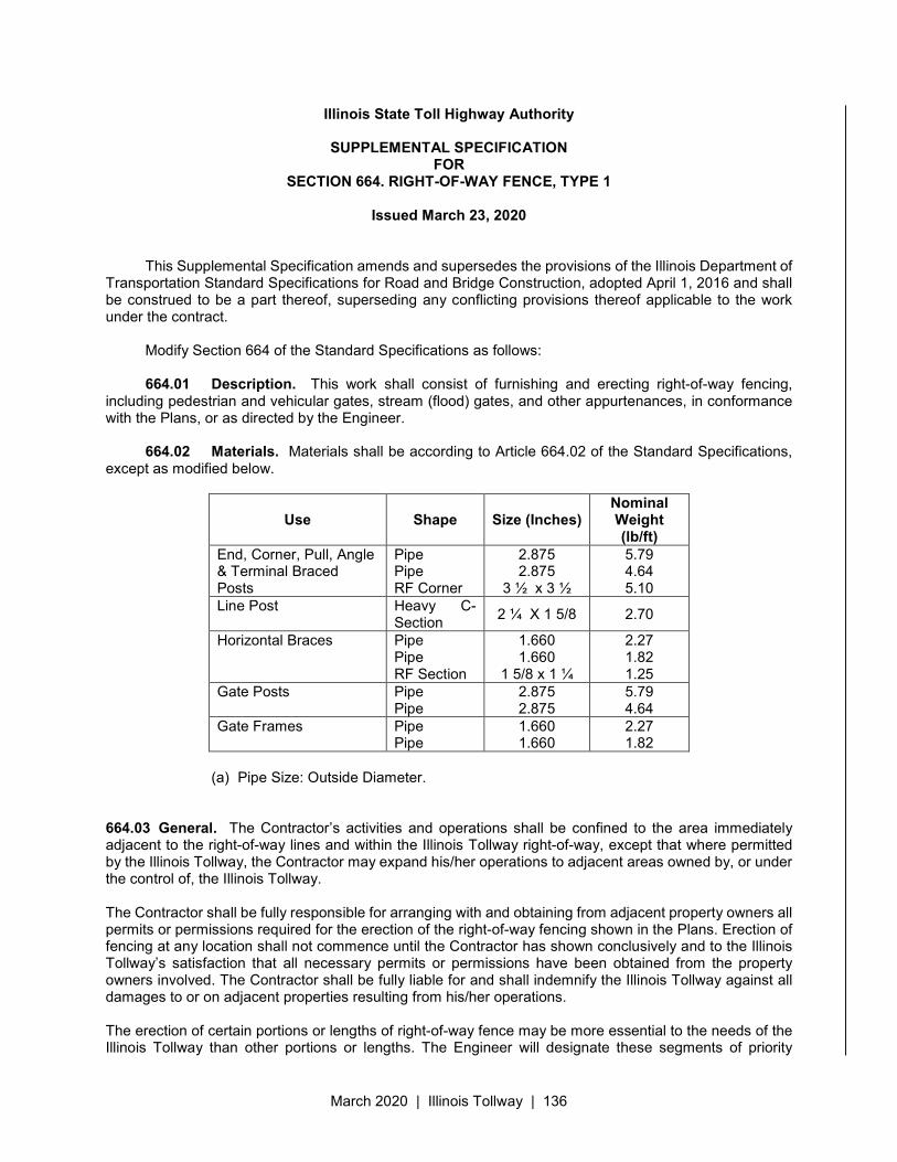
March 2020 | Illinois Tollway | 136
Illinois State Toll Highway Authority
SUPPLEMENTAL SPECIFICATION FOR
SECTION 664. RIGHT-OF-WAY FENCE, TYPE 1
Issued March 23, 2020
This Supplemental Specification amends and supersedes the provisions of the Illinois Department of Transportation Standard Specifications for Road and Bridge Construction, adopted April 1, 2016 and shall be construed to be a part thereof, superseding any conflicting provisions thereof applicable to the work under the contract.
Modify Section 664 of the Standard Specifications as follows:
664.01 Description. This work shall consist of furnishing and erecting right-of-way fencing, including pedestrian and vehicular gates, stream (flood) gates, and other appurtenances, in conformance with the Plans, or as directed by the Engineer.
664.02 Materials. Materials shall be according to Article 664.02 of the Standard Specifications,
except as modified below.
Use Shape Size (Inches) Nominal Weight (lb/ft)
End, Corner, Pull, Angle & Terminal Braced Posts
Pipe Pipe RF Corner
2.875 2.875
3 ½ x 3 ½
5.79 4.64 5.10
Line Post Heavy C-Section
2 ¼ X 1 5/8 2.70
Horizontal Braces Pipe Pipe RF Section
1.660 1.660
1 5/8 x 1 ¼
2.27 1.82 1.25
Gate Posts Pipe Pipe
2.875 2.875
5.79 4.64
Gate Frames Pipe Pipe
1.660 1.660
2.27 1.82
(a) Pipe Size: Outside Diameter.
664.03 General. The Contractor’s activities and operations shall be confined to the area immediately adjacent to the right-of-way lines and within the Illinois Tollway right-of-way, except that where permitted by the Illinois Tollway, the Contractor may expand his/her operations to adjacent areas owned by, or under the control of, the Illinois Tollway. The Contractor shall be fully responsible for arranging with and obtaining from adjacent property owners all permits or permissions required for the erection of the right-of-way fencing shown in the Plans. Erection of fencing at any location shall not commence until the Contractor has shown conclusively and to the Illinois Tollway’s satisfaction that all necessary permits or permissions have been obtained from the property owners involved. The Contractor shall be fully liable for and shall indemnify the Illinois Tollway against all damages to or on adjacent properties resulting from his/her operations. The erection of certain portions or lengths of right-of-way fence may be more essential to the needs of the Illinois Tollway than other portions or lengths. The Engineer will designate these segments of priority
March 2020 | Illinois Tollway | 137
installations and the Contractor shall conduct his/her operations as to give priority to the erection of such segments or lengths. Clearing: Prior to constructing the right of way fence, the Contractor shall clear the area, from the line of fence to a line approximately 4 feet within the line of fence, according to Section 201 of the Standard Specifications, and as directed by the Engineer. Such clearing shall be conducted in a manner to leave intact valuable trees and selected native growth. Only such trees as are directly on the line of the fence, or that would otherwise, in the opinion of the Engineer, interfere with the construction of the fence, shall be cut flush with the ground. No separate payment will be made for such clearing, but the costs thereof shall be considered as included in the Contract unit prices for the various fence items. Material Disposal: Materials removed during clearing operations shall be promptly disposed of by the Contractor as directed by the Engineer. Disposal of clearing materials within the right-of-way will be permitted only when specifically approved in writing by the Engineer. All such disposal shall be at no additional cost to the Illinois Tollway. Trench Excavation: Whenever irregular terrain exists along proposed fence lines, it may be necessary to excavate trenches to secure the specified clearances between the ground line and the bottom of the fence fabric to be installed. The trenches shall be excavated to a line and grade established by the Engineer ensuring adequate drainage and shall be of the cross sections indicated in the Plans. No separate payment will be made for such trench excavation, but the cost therefore shall be considered as included in the Contract unit price for fence to be installed. All materials excavated to form trenches shall be spread evenly over the adjacent area within the Illinois Tollway right-of-way or otherwise disposed of by the Contractor as directed by the Engineer. Painting: Metal parts which are protected by galvanizing shall not be painted. After erection is completed, all fencing under the Contract will be inspected by the Engineer, and all parts of fences, gates, stream gates, etc. (including bolts and nuts), from which the galvanizing has been abraded so that the base metal is exposed, shall be spot painted with an approved aluminum paint.
664.04 Installing Posts. All terminal corner, end, pull and/or gate posts shall be properly spaced and set in concrete. All line posts shall be properly spaced and set into the ground as in the Illinois Tollway’s Standard Drawing D1. Concrete footings shall be of Class SI concrete meeting the requirements of Section 1020 of the Standard Specifications. The footings shall be constructed to the depths shown in the Plans. The top of all footings shall extend slightly above the ground line and shall be troweled to a smooth finish with a slope to drain away from the posts. Post, braces, and other units shall be centered in the footings. Fence shall not be erected until the concrete encasement around the posts has cured for at least seven days. All excess excavation from the footings, shall be disposed of in a manner satisfactory to the Engineer. All such disposal shall be at no additional cost to the Illinois Tollway. Wherever right-of-way markers are omitted, the posts shall be set with back of post flush with the right-of-way line. The Contractor’s attention is directed to the fact that some posts may have to be placed in existing boulder beds, in old concrete foundations or other similarly solid materials. No separate payment will be made for breaking up of such material or for any material and work required to set the posts, but the cost thereof shall be considered as included in the Contract unit prices for the various fence items. The fence shall be erected to line and gradient established by the Engineer. The fence shall be true to line, taut, and shall comply with the best practice of fence construction.
March 2020 | Illinois Tollway | 138
Posts for Right-of-Way Fence, Type 1 shall be spaced in line at 10-foot centers with a tolerance of minus 2 feet. Spacing of posts shall be as uniform as conditions of terrain will permit. Additional posts shall be placed at each abrupt change in the ground line profile when required. All line posts shall be driven to the depth indicated in the Plan details in vertical plumb position, and in line, with no perceptible horizontal misalignment when sighted by eye from corner to corner. Pull posts for Right-of-Way Fence 1 shall be placed at intervals of no more than 500 feet in straight runs and at each predetermined vertical angle point. Corner posts for Right-of-Way Fence 1 shall be placed at each horizontal angle point. When the distance between corner posts exceeds 500 feet, pull posts shall be installed to maintain the maximum 500-foot interval.
664.05 Post Tops. Post tops shall be according to Article 664.05 of the Standard Specifications.
664.06 Tension Wire. Tension wire shall be according to Article 664.06 of the Standard Specifications.
664.07 Braces. Braces shall be according to Article 664.07 of the Standard Specifications.
664.08 Fabric. Fabric shall be according to Article 664.08 of the Standard Specifications. The fence fabric shall be placed normally at 1 1/2 inches above the ground line. However, over irregular terrain, a minimum clearance of one inch and a maximum clearance of 6 inches will be permitted for a distance not to exceed 8 feet. Any excavation required in order to comply with these provisions shall be made as specified in Trench Excavation in this specification.
664.09 Gates. Gates shall be according to Article 664.09 of the Standard Specifications with the addition of the following:
Gates shall consist of pedestrian gates and single and/or double vehicular gates of the types and sizes shown in the Plans. Fabric for gates shall be of the same type as used in the adjoining fence. Gates shall be equipped with approved latches, stops, hinges, and locking devices. Hinges shall be heavy-duty malleable iron, pivot type, with large bearing surfaces for clamping onto the posts. Hinges shall not twist or turn under the action of the gate, and shall be so arranged that a closed gate cannot be lifted off its hinges to obtain entry. Vehicular gates shall have a 180 degree opening swing. Pedestrian gates shall be equipped with a positive stop which will not permit the gate to swing toward the Toll Highway and shall provide a satisfactory spring or other positive means to maintain the gate in a closed position. The pedestrian and vehicular gate installation shall include gate frames, tie rods, stretcher bars, filler fabric, latches, stops, locking device, padlock, hinges, gate posts with braces, tie rods, turnbuckles, stretcher bars and caps, and all fittings and details for gates and gate posts, all as specified and as shown in the Plans, and as required to make a complete installation.
March 2020 | Illinois Tollway | 139
The Contractor shall furnish an approved-type padlock for each gate. Each padlock shall be master keyed to the Illinois Tollway’s lock system as directed. Prior to fabricating any gates, the Contractor shall investigate the conditions at the site and shall prepare shop drawings in accordance with Article 105.04 (d) of the Illinois Tollway Supplemental Specifications showing the details of the proposed installation. Four complete sets of the shop drawings shall be submitted to the Engineer for approval. Fabrication of gates shall not be started until the shop drawings have been approved by the Engineer. Stream Gates (Flood Gates): The Contractor shall furnish and erect stream gates (flood gates) for stream and culvert crossings in conformance with, and at the locations shown in the Plans and as specified herein. Prior to fabricating any gates, the Contractor shall investigate the conditions at the site and shall prepare shop drawings in accordance with Article 105.04 (d) of the Illinois Tollway Supplemental Specifications showing the details of the proposed installation. Four complete sets of the shop drawings shall be submitted to the Engineer for approval. Fabrication of gates shall not be started until the shop drawings have been approved by the Engineer. Stream Crossing: Where RIGHT-OF-WAY FENCE crosses streams, drainage channels, or sharp depressions in the terrain, Stream Crossing will be required at the locations shown in the Plans and/or directed by the Engineer. Stream crossings shall be constructed in accordance with the Plan details for TYPE 1 or TYPE 2 as indicated in the Plans or directed by the Engineer. In the usual circumstances, TYPE 1 STREAM CROSSING will be required for locations where there normally is no flow of water. Extra-length posts will be required at stream crossings. Posts at stream crossings may be driven, except that posts more than 9 feet in length shall be set in concrete. The openings below the fence fabric or gate at stream crossings shall be closed with No. 12-1/2 gage barbed wire stretched between the posts as shown in the Plans. The finished fence shall be plumb, taut, true to line and ground contour, and complete in every detail. Where directed, the Contractor will be required to stake down the chain link fence at several points between posts.
664.10 Existing Fence Connections. Existing fence connections shall be according to Article 664.10 of the Standard Specifications. Connection to Bridge Abutment: Fence post connections adjacent to the concrete abutments at bridge structures shall be connected to the abutments in accordance with the details shown on Illinois Tollway Standard Drawing D1 or in the Plans. The bands around the posts may be of rolled, pressed, or forged steel or of malleable iron, and shall have a tight fit around posts. Bands and connection angles shall be hot-dip galvanized in conformity with ASTM A123. Bolts shall be unfinished and shall have hexagonal head and nut and standard thread. Bolts shall be drawn up tight and the threads burred with a pointed tool.
664.11 Protective Electrical Ground. Protective electric ground shall be according to Article 664.11 of the Standard Specifications.
664.12 Method of Measurement. The fencing work will be measured for payment, complete in place, in units as specified herein: RIGHT-OF-WAY FENCE, of the type specified will be measured for payment in feet for fence erected, from center to center of end or terminal posts and will exclude the lengths occupied by pedestrian and vehicular gates, stream crossings and stream gates. The measured length of fencing will be basis for payment of fabric, barb and tension wire, line posts, and all connections required to erect the fencing.
March 2020 | Illinois Tollway | 140
CORNER POSTS, PULL POSTS, END POSTS, and END POSTS CONNECTED TO STRUCTURES will be measured for payment on a unit basis for each type of post erected and will include all bracing, tension rods, concrete, and necessary connections. PEDESTRIAN GATE, SINGLE VEHICULAR GATE, and DOUBLE VEHICULAR GATE will be measured for payment on a unit basis for each type and size of gate erected and will include the gate posts, bracing, tension rods, concrete, and other necessary fastenings and connections. STREAM or FLOOD GATES will be measured for payment per square foot for the size and type specified. STREAM CROSSINGS will be measured for payment in feet for each type of stream crossing erected, and will include Right-of-Way Fence, of the type specified, and the barb wire below the right-of-way fencing. Measurement will be from end to end of the crossing section as determined by the Engineer.
664.13 Basis of Payment. The fencing work will be paid for at the contract unit price as specified herein: Payment for RIGHT-OF-WAY FENCE, TYPE 1, will be made at the Contract unit price per foot as specified, complete in place and accepted. Payment for CORNER POST, PULL POST and END POST will be made at the Contract unit price per each, complete in place and accepted, for posts of the lengths shown in the Plans for RIGHT-OF-WAY FENCE, of the TYPE specified. Payment for PEDESTRIAN GATE, SINGLE VEHICULAR GATE and DOUBLE VEHICULAR GATE will be made at the Contract unit price per each, complete in place and accepted, for gates of the description shown in the Plans for RIGHT-OF-WAY FENCE, of the TYPE specified. Payment for STREAM OR FLOOD GATE will be made at the Contract unit price per square foot, complete in place and accepted. Payment for STREAM CROSSING will be made at the Contract unit price per foot, complete in place and accepted, as shown in the Plans for STREAM CROSSING, TYPE 1.
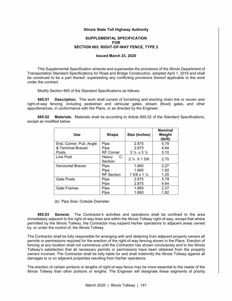
March 2020 | Illinois Tollway | 141
Illinois State Toll Highway Authority
SUPPLEMENTAL SPECIFICATION FOR
SECTION 665. RIGHT-OF-WAY FENCE, TYPE 2
Issued March 23, 2020
This Supplemental Specification amends and supersedes the provisions of the Illinois Department of Transportation Standard Specifications for Road and Bridge Construction, adopted April 1, 2016 and shall be construed to be a part thereof, superseding any conflicting provisions thereof applicable to the work under the contract.
Modify Section 665 of the Standard Specifications as follows:
665.01 Description. This work shall consist of furnishing and erecting chain link or woven wire right-of-way fencing, including pedestrian and vehicular gates, stream (flood) gates, and other appurtenances, in conformance with the Plans, or as directed by the Engineer.
665.02 Materials. Materials shall be according to Article 665.02 of the Standard Specifications, except as modified below.
Use Shape Size (Inches) Nominal Weight (lb/ft)
End, Corner, Pull, Angle & Terminal Braced Posts
Pipe Pipe RF Corner
2.875 2.875
3 ½ x 3 ½
5.79 4.64 5.10
Line Post Heavy C-Section
2 ¼ X 1 5/8 2.70
Horizontal Braces Pipe Pipe RF Section
1.660 1.660
1 5/8 x 1 ¼
2.27 1.82 1.25
Gate Posts Pipe Pipe
2.875 2.875
5.79 4.64
Gate Frames Pipe Pipe
1.660 1.660
2.27 1.82
(b) Pipe Size: Outside Diameter.
665.03 General. The Contractor’s activities and operations shall be confined to the area immediately adjacent to the right-of-way lines and within the Illinois Tollway right-of-way, except that where permitted by the Illinois Tollway, the Contractor may expand his/her operations to adjacent areas owned by, or under the control of, the Illinois Tollway. The Contractor shall be fully responsible for arranging with and obtaining from adjacent property owners all permits or permissions required for the erection of the right-of-way fencing shown in the Plans. Erection of fencing at any location shall not commence until the Contractor has shown conclusively and to the Illinois Tollway’s satisfaction that all necessary permits or permissions have been obtained from the property owners involved. The Contractor shall be fully liable for and shall indemnify the Illinois Tollway against all damages to or on adjacent properties resulting from his/her operations. The erection of certain portions or lengths of right-of-way fence may be more essential to the needs of the Illinois Tollway than other portions or lengths. The Engineer will designate these segments of priority

March 2020 | Illinois Tollway | 142
installations and the Contractor shall conduct his/her operations as to give priority to the erection of such segments or lengths. Clearing: Prior to constructing the right of way fence, the Contractor shall clear the area, from the line of fence to a line approximately 4 feet within the line of fence, according to Section 201 of the Standard Specifications, and as directed by the Engineer. Such clearing shall be conducted in a manner to leave intact valuable trees and selected native growth. Only such trees as are directly on the line of the fence, or that would otherwise, in the opinion of the Engineer, interfere with the construction of the fence, shall be cut flush with the ground. No separate payment will be made for such clearing, but the costs thereof shall be considered as included in the Contract unit prices for the various fence items. Material Disposal: Materials removed during clearing operations shall be promptly disposed of by the Contractor as directed by the Engineer. Disposal of clearing materials within the right-of-way will be permitted only when specifically approved in writing by the Engineer. All such disposal shall be at no additional cost to the Illinois Tollway. Trench Excavation: Whenever irregular terrain exists along proposed fence lines, it may be necessary to excavate trenches to secure the specified clearances between the ground line and the bottom of the fence fabric to be installed. The trenches shall be excavated to a line and grade established by the Engineer ensuring adequate drainage and shall be of the cross sections indicated in the Plans. No separate payment will be made for such trench excavation, but the cost therefore shall be considered as included in the Contract unit price for fence to be installed. All materials excavated to form trenches shall be spread evenly over the adjacent area within the Illinois Tollway right-of-way or otherwise disposed of by the Contractor as directed by the Engineer. Painting: Metal parts which are protected by galvanizing shall not be painted. After erection is completed, all fencing under the Contract will be inspected by the Engineer, and all parts of fences, gates, stream gates, etc. (including bolts and nuts), from which the galvanizing has been abraded so that the base metal is exposed, shall be spot painted with an approved aluminum paint.
665.04 Installing Posts. All terminal corner, end, pull and/or gate posts shall be properly spaced and set in concrete. All line posts shall be properly spaced and set into the ground as in the Illinois Tollway’s Standard Drawing D1. Concrete footings shall be of Class SI concrete meeting the requirements of Section 1020 of the Standard Specifications. The footings shall be constructed to the depths shown in the Plans. The top of all footings shall extend slightly above the ground line and shall be troweled to a smooth finish with a slope to drain away from the posts. Post, braces, and other units shall be centered in the footings. Fence shall not be erected until the concrete encasement around the posts has cured for at least seven days. All excess excavation from the footings, shall be disposed of in a manner satisfactory to the Engineer. All such disposal shall be at no additional cost to the Illinois Tollway. Wherever right-of-way markers are omitted, the posts shall be set with back of post flush with the right-of-way line. The Contractor’s attention is directed to the fact that some posts may have to be placed in existing boulder beds, in old concrete foundations or other similarly solid materials. No separate payment will be made for breaking up of such material or for any material and work required to set the posts, but the cost thereof shall be considered as included in the Contract unit prices for the various fence items. The fence shall be erected to line and gradient established by the Engineer. The fence shall be true to line, taut, and shall comply with the best practice of fence construction.
March 2020 | Illinois Tollway | 143
Posts for Right-of-Way Fence, Type 2 shall be spaced in line at 12 foot-6 inch centers with a tolerance of minus 2 feet. Spacing of posts shall be as uniform as conditions of terrain will permit. Line posts for Type 2 Fencing shall include a firmly attached, tapered, minimum 12 gauge anchor plate of not less than 21 square inches, unless otherwise shown in the Plans or specified in the Special Provisions. Additional posts shall be placed at each abrupt change in the ground line profile when required. All line posts shall be driven to the depth indicated in the Plan details in vertical plumb position, and in line, with no perceptible horizontal misalignment when sighted by eye from corner to corner. Pull posts for Right-of-Way Fence, Type 2 shall be placed at intervals of no more than 330 feet in straight runs and at each predetermined vertical angle point. Corner posts for Right-of-Way Fence, Type 2 shall be placed at each horizontal angle point. When the distance between corner posts exceeds 330 feet, pull posts shall be installed to maintain the maximum 330-foot interval.
665.05 Post Tops. All hollow pipe and tube type posts shall be fitted with post tops. The bases of the post tops shall have flanges which fit around the outside of the posts and shall be secured in place.
665.06 Tightening and Splicing. Barbed and woven wire shall be pulled tight, according to standard practice and the recommendations of the manufacturer, and shall be fastened to metal posts by means of wire, clips or other suitable fasteners. Splicing barbed or woven wire shall be accomplished by using either a wrapped splice or a corrosive resistant, compressed sleeve type splice meeting the approval of the Engineer. When a wrapped splice is used for woven wire, the vertical wires adjacent to the ends shall be brought together and the end of each horizontal wire wrapped not less than six complete turns around the other corresponding horizontal wire. When barbed wire is spliced, each end shall be wrapped not less than six complete turns around the other wire.
665.07 Braces. When required by the plans, braces shall be placed 12 in. down from the top of the terminal posts and shall extend from the terminal (end, corner and pull) posts and gate posts to the brace posts. The braces shall be securely fastened to the post and trussed from brace post back to terminal posts with 3/8 in. round rods with a turnbuckle.
665.08 Fabric. The fence fabric shall be placed normally at 3 inches above the ground line. However, over irregular terrain, a minimum clearance of one inch and a maximum clearance of 6 inches will be permitted for a distance not to exceed 8 feet. Any excavation required in order to comply with these provisions shall be made as specified in Trench Excavation in this specification. The fabric shall be unrolled on the outside of the fence line with the bottom edge of the fabric against the posts. The various rolls shall be spliced by bringing the ends close together and weaving in a picket in such a way that it will engage both of the roll ends and catch with each twist each separate mesh of the end pickets of both rolls of fabric. At end, corner or gate posts, the stretcher bar shall be slipped through the end picket of the fabric and the stretcher bar bands at the same time. Then the bolts in the stretcher bar bands shall be tightened. Additional rolls of fabric shall be spliced and placed as the erection progresses along the fence. In long sections, the fence shall be stretched at intervals of about 100 ft. The fabric shall be placed by securing one end and applying sufficient tension to remove all slack before making attachments elsewhere. After the fabric has been stretched, it shall be tied to the tension wire with fabric ties spaced not more than 24 in. apart. The fabric shall then be attached to the line posts with fabric ties spaced not more than 14 in. apart. The topmost clip shall be placed on the line post as near the top of the fabric as possible and the lowest
March 2020 | Illinois Tollway | 144
clip as near the bottom of the fabric as possible. At terminal (end, corner and pull) and gate posts, the fabric shall be fastened with stretcher bars and bands. The fasteners shall be spaced not more than 14 in. on centers for terminal (end, corner and pull) and gate posts. The topmost band shall be placed on these posts as near the top of the fabric as possible and the lowest band as near the bottom as possible. Standard chain link fence stretching equipment shall be provided for stretching the fabric before tying it to the tension wire and posts. The stretching and tying operations shall be repeated about every 100 ft. until the fun of fence is completed. Before making a closure, the other end of the run shall be fastened to the end, corner or gate post as described previously. The operation of making a closure of a run shall be as follows: The stretching equipment shall be clamped on the ends of the fabric parallel to each other and about 5 ft. apart when the tension is first applied. The stretching shall continue until the slack has been removed from both sections of the fabric. If the ends overlap, the fabric shall be cut to match. The ends shall be joined by the insertion of a picket similar to the methods of connecting two rolls of fabric.
665.09 Gates. Gates shall be hung on gate fittings as shown on the plans. The lower hinge (ball and socket type) shall be placed on top of the concrete in which the gate post is set. The sockets for the cane or foot bolts shall be set in concrete so that the plunger pin will fit perfectly in the socket when the gate is in a closed position. Gates shall be erected as to swing in the direction indicated and shall be provided with gate stops as specified or shown on the plans. Gate keepers shall be provided to hold gates when in open position, and shall be located and installed as directed by the Engineer. Gates shall be erected in suitable places as shown on the plans. All hardware shall be thoroughly secured, properly adjusted and left in perfect working order. Hinges and diagonal bracing in gates shall be adjusted so that gates will hang level.
Gates shall consist of pedestrian gates and single and/or double vehicular gates of the types and sizes shown in the Plans. Fabric for gates shall be of the same type as used in the adjoining fence. Gates shall be equipped with approved latches, stops, hinges, and locking devices. Hinges shall be heavy-duty malleable iron, pivot type, with large bearing surfaces for clamping onto the posts. Hinges shall not twist or turn under the action of the gate, and shall be so arranged that a closed gate cannot be lifted off its hinges to obtain entry. Vehicular gates shall have a 180 degree opening swing. Pedestrian gates shall be equipped with a positive stop which will not permit the gate to swing toward the Toll Highway and shall provide a satisfactory spring or other positive means to maintain the gate in a closed position. The pedestrian and vehicular gate installation shall include gate frames, tie rods, stretcher bars, filler fabric, latches, stops, locking device, padlock, hinges, gate posts with braces, tie rods, turnbuckles, stretcher bars and caps, and all fittings and details for gates and gate posts, all as specified and as shown in the Plans, and as required to make a complete installation. The Contractor shall furnish an approved-type padlock for each gate. Each padlock shall be master keyed to the Illinois Tollway’s lock system as directed. Prior to fabricating any gates, the Contractor shall investigate the conditions at the site and shall prepare shop drawings in accordance with Article 105.04 (d) of the Illinois Tollway Supplemental Specifications showing the details of the proposed installation. Four complete sets of the shop drawings shall be submitted to the Engineer for approval. Fabrication of gates shall not be started until the shop drawings have been approved by the Engineer.
March 2020 | Illinois Tollway | 145
Stream Gates (Flood Gates): The Contractor shall furnish and erect stream gates (flood gates) for stream and culvert crossings in conformance with, and at the locations shown in the Plans and as specified herein. Prior to fabricating any gates, the Contractor shall investigate the conditions at the site and shall prepare shop drawings in accordance with Article 105.04 (d) of the Illinois Tollway Supplemental Specifications showing the details of the proposed installation. Four complete sets of the shop drawings shall be submitted to the Engineer for approval. Fabrication of gates shall not be started until the shop drawings have been approved by the Engineer. Stream Crossing: Where RIGHT-OF-WAY FENCE crosses streams, drainage channels, or sharp depressions in the terrain, Stream Crossing will be required at the locations shown in the Plans and/or directed by the Engineer. Stream crossings shall be constructed in accordance with the details for TYPE 2 as indicated in the Plans or directed by the Engineer. Extra-length posts will be required at stream crossings. Posts at stream crossings may be driven, except that posts more than 9 feet in length shall be set in concrete. The openings below the fence fabric or gate at stream crossings shall be closed with No. 12-1/2 gage barbed wire stretched between the posts as shown in the Plans. The finished fence shall be plumb, taut, true to line and ground contour, and complete in every detail. Where directed, the Contractor will be required to stake down the chain link fence at several points between posts.
665.10 Existing Fence Connections. Wherever a new fence joins an existing fence, either at a corner or at the intersection of straight line fences, a corner post with brace post shall be set at the junction and braced the same as described for corner posts or as shown on the plans. If the connection is made at other than the corner of the new fence, the last span of the old fence shall contain a brace span. Connection to Bridge Abutment: Fence post connections adjacent to the concrete abutments at bridge structures shall be connected to the abutments in accordance with the details shown on Illinois Tollway Standard Drawing D1 or in the Plans. The bands around the posts may be of rolled, pressed, or forged steel or of malleable iron, and shall have a tight fit around posts. Bands and connection angles shall be hot-dip galvanized in conformity with ASTM A123. Bolts shall be unfinished and shall have hexagonal head and nut and standard thread. Bolts shall be drawn up tight and the threads burred with a pointed tool.
665.11 Protective Electrical Ground. Continuous fence shall be grounded at intervals not exceeding 500 ft. in urban areas and 1000 ft. in rural areas. There shall be a ground within 100 ft. of gates in each section of the fence adjacent to the gate.
665.12 Method of Measurement. The fencing work will be measured for payment, complete in place, in units as specified herein: RIGHT-OF-WAY FENCE, of the type specified will be measured for payment in feet for fence erected, from center to center of end or terminal posts and will exclude the lengths occupied by pedestrian and vehicular gates, stream crossings and stream gates. The measured length of fencing will be basis for payment of fabric, barb and tension wire, line posts, and all connections required to erect the fencing. CORNER POSTS, PULL POSTS, END POSTS, and END POSTS CONNECTED TO STRUCTURES will be measured for payment on a unit basis for each type of post erected and will include all bracing, tension rods, concrete, and necessary connections.
March 2020 | Illinois Tollway | 146
PEDESTRIAN GATE, SINGLE VEHICULAR GATE, and DOUBLE VEHICULAR GATE will be measured for payment on a unit basis for each type and size of gate erected and will include the gate posts, bracing, tension rods, concrete, and other necessary fastenings and connections. STREAM or FLOOD GATES will be measured for payment per square foot for the size and type specified. STREAM CROSSINGS will be measured for payment in feet for each type of stream crossing erected, and will include Right-of-Way Fence, of the type specified, and the barb wire below the right-of-way fencing. Measurement will be from end to end of the crossing section as determined by the Engineer.
665.13 Basis of Payment. The fencing work will be paid for at the contract unit price as specified herein: Payment for RIGHT-OF-WAY FENCE, TYPE 2, will be made at the Contract unit price per foot as specified, complete in place and accepted. Payment for CORNER POST, PULL POST and END POST will be made at the Contract unit price per each, complete in place and accepted, for posts of the lengths shown in the Plans for RIGHT-OF-WAY FENCE, of the TYPE specified. Payment for PEDESTRIAN GATE, SINGLE VEHICULAR GATE and DOUBLE VEHICULAR GATE will be made at the Contract unit price per each, complete in place and accepted, for gates of the description shown in the Plans for RIGHT-OF-WAY FENCE, of the TYPE specified. Payment for STREAM OR FLOOD GATE will be made at the Contract unit price per square foot, complete in place and accepted. Payment for STREAM CROSSING will be made at the Contract unit price per foot, complete in place and accepted, as shown in the Plans for STREAM CROSSING, TYPE 2
March 2020 | Illinois Tollway | 147
Illinois State Toll Highway Authority
SUPPLEMENTAL SPECIFICATION FOR
SECTION 666. RIGHT-OF-WAY MARKERS
Issued March 23, 2020
This Supplemental Specification amends and supersedes the provisions of the Illinois Department of Transportation Standard Specifications for Road and Bridge Construction, adopted April 1, 2016 and shall be construed to be a part thereof, superseding any conflicting provisions thereof applicable to the work under the contract.
Modify Section 666 of the Standard Specifications as follows:
666.02 Materials. Materials shall be according to the following provisions of the Standard Specifications.
Item Article (a) Precast Concrete Right-of-Way Markers ............................................1042.13 (b) Reinforcement Bars ........................................................................... 1006.10 (c) The Markers shall be in accordance with the Illinois Tollway Standard D3.
CONSTRUCTION REQUIREMENTS
666.03 Furnishing and Erecting. Right-of-Way Markers shall be set so the back of the post is flush with the right-of-way line, except when the marker conflicts with a property pin, in which case the right-of-way marker shall be offset. The markers shall be set in compacted soil, and the bottom of the holes shall be rammed to provide a stable foundation. They shall be set in a vertical position with the lettered side facing the roadbed. The holes shall be backfilled and compacted with approved materials in layers in such manner that the bottom of the markers will remain in the correct position. Right-of-Way Markers shall be erected before any grading operations are started, except that markers in easement areas may be erected after the final grading is complete. The Engineer will perform all survey work necessary for establishing the locations of the Right-of-Way Markers. Markers shall be set accurately at the established locations. Any marker not set properly shall be removed and reset by the Contractor at no additional cost to the Illinois Tollway.
666.04 Existing Right-of-Way Markers. Existing markers which are not required to be disturbed or reestablished shall be adequately protected by the Contractor during construction. Any Right-of-Way Markers which are disturbed by the Contractor during his/her construction operations shall be re-established at no additional cost to the Illinois Tollway.
666.05 Method of Measurement. This work will be measured in units of each.
666.06 Basis of Payment.
Payment for RIGHT-OF-WAY MARKER will be made at the contract unit price per each. Payment for RIGHT OF WAY MARKER (SPECIAL) will be made at the contract unit price per each.
March 2020 | Illinois Tollway | 148
Illinois State Toll Highway Authority
SUPPLEMENTAL SPECIFICATION FOR
SECTION 670. ENGINEERS FIELD OFFICE AND LABORATORY
Issued April 1, 2016
This Supplemental Specification amends and supersedes the provisions of the Illinois Department of Transportation Standard Specifications for Road and Bridge Construction, adopted April 1, 2016 and shall be construed to be a part thereof, superseding any conflicting provisions thereof applicable to the work under the contract.
Delete Section 670 of the Standard Specifications in its entirety and replace with the following
670.01 Description and Special Conditions
(a) General. This work shall consist of furnishing and maintaining field offices and field laboratories, including telephone services, heat, air conditioning, electricity, water, sanitary facilities, and janitor service, and furnishings in accordance with these Specifications. The number of offices and laboratories to be provided shall be as specified in the Special Provisions. The location of offices and laboratories shall be as specified in the Special Provisions or as approved by the Engineer.
(b) Penalty. Failure by the Contractor to meet the specified occupancy date for any field office or field laboratory shall be grounds for assessment of a penalty of $500 per day for each calendar day thereafter that such facility remains incomplete in any respect. Failure by the Contractor to equip, heat, cool, power, supply or clean the field office shall be grounds for assessment at a penalty of $500 per day for each calendar day that the field office remains incomplete after receipt of written notification from the Engineer. Such penalty shall be deducted from monies due or to become due the Contractor under the Contract.
670.02 General Requirements. The buildings for offices and laboratories may be of new construction conforming to the requirements hereinafter specified, or the Contractor may rent or otherwise provide mobile units or suitable existing buildings of equivalent space and facilities in lieu of new buildings, subject to the approval of the Engineer.
Unless otherwise specified or approved, field offices and field laboratories to be provided and maintained by the Contractor shall be independent of any facilities used by the Contractor, and all keys to such offices and laboratories shall be turned over to the Engineer.
Unless otherwise approved by the Illinois Tollway each specified field office and field laboratory shall be fully equipped and complete in all respects and available for occupancy by the Engineer not later than 10 calendar days after the effective date of Notice to Proceed, and shall be maintained by the Contractor to the satisfaction of the Engineer throughout the term of the contract and for a period of not less than 2 weeks after the certified Date of Completion or any authorized extension thereof.
Electrical service shall be 120-240V, min. 100 amps, capable of supporting anticipated electrical loads.
Telephone service shall be provided by the Contractor for each field office and laboratory as hereinafter specified. Such service shall be independent of and not connected to or extended from the Contractor’s or any other telephone service unless specifically requested by the Engineer. Telephone instruments shall be touch-tone, two-line, and six button units with “hold” and “inter-com” capability. The installation, monthly charges and billings for all calls within area codes 312, 773, 630, 708, 815 and 847
March 2020 | Illinois Tollway | 149
shall be paid by the Contractor. Call-waiting shall be provided. Billings for calls to all other area codes may be presented to the Engineer for reimbursement.
If, during any extended delay or suspension of the work, any field office or laboratory is vacated by the Engineer for the convenience of the Illinois Tollway, the Contractor shall assure the physical security of such premises and shall indemnify the Engineer against loss due to fire, flood, storm, theft, vandalism and other causes beyond the control of the Engineer. The Engineer shall not be required to remove or otherwise provide for the security of property and installed equipment for the purpose of minimizing the Contractor’s liability under this requirement.
Parking spaces for not less than 8 passenger cars and/or trucks of not more than 8000 lbs. GVW shall be available at all times adjacent to each field office and laboratory for exclusive use by the Engineer, the Illinois Tollway, the Consulting Engineer, and their respective employees, agents, and representatives.
Where there is insufficient area of all-weather surface to meet the parking requirements, the Contractor shall remove vegetation and top soil, grade the selected area to drain, and place material meeting the requirements of Article 351.02 of the Standard Specifications in sufficient thickness to provide an all-weather surface for the specified vehicles. Upon expiration of the specified period of occupancy, the Contractor shall restore such parking areas to their original, or better, condition. Achievement of acceptable restoration may require the Contractor to apply any or all of the treatments specified in Sections 250, 252, 253, 254 of the Standard Specifications, and 280 as may be required by the Illinois Tollway.
All costs incurred by the Contractor in providing, preparing, surfacing, and restoring parking areas shall be considered as included in the Contract unit price for Field Office and/or Field Laboratory.
At the discretion and for the convenience of the Illinois Tollway, the Contractor may be given permission to locate field offices or laboratories on Illinois Tollway property. Such permission shall not relieve the Contractor of any responsibility for compliance with the requirements of this Section.
670.03 Field Office
(a) General. The Contractor shall provide and maintain in good condition, a field office partitioned as directed by the Engineer, into not more than two offices, one washroom and two closets.
Each field office shall meet the following requirements:
(1) Ceiling: Minimum ceiling height to be 7"-0".
(2) Openings: Minimum of one exterior door to be provided.
(3) Signs: One sign identifying the Engineer, approximately 2'0" x 4'-0", provided, lettered, and placed by the Contractor as directed by the Engineer.
(4) Washroom Facilities: Minimum of one flush toilet and one wash basin to be provided. If similar nearby washroom facilities are available for use, and are acceptable to the Engineer, washroom facilities need not be provided in the field office.
(5) Closets: Equipped with locked doors and shelves as requested by the Engineer.
(6) Heating, Electrical, and Air Conditioning: Each field office shall be equipped with forced air, hot water or electric heat, electric services including adequate necessary fixtures and wall outlets as determined by the Engineer, air conditioning, and telephone service. The heating system shall be able to maintain a minimum temperature of 70°F and the air-conditioning system shall be able to maintain a maximum of 75°.
March 2020 | Illinois Tollway | 150
(7) Furnishings: The following equipment and furniture, meeting the approval of the Engineer, shall be provided by the Contractor for use in field office:
a. 2 desks and 2 rolling chairs with upholstered seat & back.
b. 1 drafting table 371/2” x 48" and upholstered stool
c. 1 file cabinet, legal size, 4 drawers, with lock
d. 4 chairs
e. 1 equipment cabinet with lock
f. 1 carbon dioxide fire extinguisher (10 lb. rated capacity)
g. 1 water cooler dispenser
h. 1 first aid kit
i. 1 copy machine capable of making 81/2" X 11" to 11" X 17" copies. The Contractor shall pay installation and rental charges, and shall provide all supplies and equipment necessary for operation of the copier.
j. 1 scanner that meets the requirement of Article 105.19(c).
(8) Mail Service: In urban and suburban areas, the Contractor shall obtain and pay the rent on behalf of the Engineer for a post office box at the nearest or most accessible local post office. In rural areas, the Contractor shall obtain permission from the local postmaster and install, for the exclusive use of the Engineer, a mail box near one designated field office for the delivery and pick-up of mail.
(9) Janitorial Service: The field office shall be cleaned weekly, during normal working hours.
(10) Security Alarm System: This system shall provide door contacts, combination microwave and passive infrared detectors and smoke detectors. This system shall activate an exterior alarm and shall send the alarm signal to a security service through telephone lines also utilizing a radio back-up system to the security service.
(11) Broadband Internet Connectivity: The Contractor must establish broadband Internet connectivity in the Field Office for exclusive use of Illinois Tollway personnel and the Construction Manager in order to effectively utilize the Web-based Program Management System. T1, Cable modem, or DSL connectivity is acceptable.”
(b) Field Office Classification. Field offices shall be classified for payment according to floor area and special features required.
All field offices shall comply with Article 670.03 (a) as minimum requirements.
(1) FIELD OFFICE, TYPE A
a. Minimum floor space - 240 square feet.
b. Special features - Field office shall be provided with three private telephone lines and three three-line touch-tone telephones as hereinbefore specified. The Contractor shall pay installation, service, and removal charges, together with the billings for all calls within the area codes of 312, 773, 630, 708, 815
March 2020 | Illinois Tollway | 151
and 847. Telephone service shall remain connected throughout the specified period of occupancy regardless of delays or suspensions of work. These lines shall have “call-waiting”. All of the telephone lines provided shall have an unpublished number.
(2) FIELD OFFICE, TYPE B
a. Minimum floor space - 500 square feet.
b. Special features - a facsimile machine with maintenance agreement and supplies, subject to the approval of the Engineer.
c. In addition to the touch-tone telephone service for FIELD OFFICE, TYPE A, two additional telephone lines shall be provided. One is to be used with a fixed modem for direct two-way communication with off-site computer equipment. The other line is for the exclusive service of the facsimile machine. Such telephone lines shall remain available for the exclusive use of the Engineer throughout the specified period of occupancy regardless of delays or suspensions of work. The lines shall not have “call-waiting”. All of the telephone lines provided shall have an unpublished number.
d. In addition to Article 670.03(a), the photocopy machine shall be subject to the following additional requirements:
Minimum rate of 30 copies per minute. Reduce and enlarge capabilities. Darkening and lightening capabilities. Collating capabilities. Original & copy sizes 81/2" x 14" & 11" x 17" The Contractor shall pay installation and rental charges, and shall provide all paper, supplies and equipment necessary for operation of the copier.
(3) FIELD OFFICE, TYPE C
a. Minimum floor space 1000 square feet.
b. Special Features - Same as FIELD OFFICE, TYPE B.
(4) FIELD OFFICE, TYPE C (MODIFIED)
a. Minimum floor space 2000 square feet.
b. Special features - same as FIELD OFFICE, TYPE B plus the following:
c. Twelve 72" x 30" desks and rolling chairs.
d. 200 feet of 13" high x 10" deep shelving.
e. 40 feet of 13" high x 24" deep heavy duty shelving.
f. 10 file cabinets, letter size, 2 drawers.
g. four drawer legal size, insulated file cabinets.
h. 14 clamp-mounted incandescent desk lamps.,
i. Rolling, floor rack with capacity for 24 plan clamps along with 24 plan hanging clamps.
j. Coat rack with top shelf 48" long.
k. 4' x 8' cork bulletin board.
l. 4' x 8' white board.
March 2020 | Illinois Tollway | 152
m. 25" x 20" x 29" Copier stand with two shelves
n. desk dividers.
o. 5 drawer steel flat file for plan drawings.
p. 1 office style refrigerator with a minimum size of 8 cu-ft.
670.04 Field Laboratory. The Contractor shall provide and maintain in good condition, in the near vicinity of the FIELD OFFICE or as directed by the Engineer, a laboratory for the exclusive use of the Engineer for inspection and testing of materials as required for the Contract.
Each laboratory shall have a floor area of not less than 240 square feet (approximately 8' X 30') partitioned as directed by the Engineer into one work space, one washroom, and one closet. Its general construction, equipment, and facilities shall be the same as prescribed for the Field Office, Type A, except as follows:
(a) Should the Engineer so direct, one of the telephones provided for the field office shall be installed in the FIELD LABORATORY.
(b) In the event nearby washroom facilities are available, the Contractor will not be required to furnish such facilities for the FIELD LABORATORY.
The following equipment and furnishings, meeting the approval of the Engineer, shall be provided for use in the field laboratory:
1 hooded exhaust fan of at least 750 cfm at the work station where bituminous extraction tests will be performed
1 desk and chair 1 drafting table and stool 1 file cabinet, legal size, 4 drawers 2 chairs 1 equipment cabinet with lock 1 carbon dioxide fire extinguisher (10 lb. rated capacity) 1 water cooler dispenser 1 first aid kit
670.05 Method of Measurement. FIELD OFFICE, TYPE A; FIELD OFFICE, TYPE B; FIELD OFFICE, TYPE C; FIELD OFFICE, TYPE C (MODIFIED) and FIELD LABORATORY will be measured for payment on a per building or unit basis per month for each type of field office or field laboratory provided and maintained by the Contractor.
670.06 Basis of Payment. Payment for FIELD OFFICE, TYPE A; FIELD OFFICE, TYPE B; FIELD OFFICE, TYPE C; FIELD OFFICE, TYPE C (MODIFIED) and FIELD LABORATORY will be made at the Contract Unit price per each/per month, which payment shall constitute full compensation for furnishing the specified unit, (office or laboratory) complete with all enumerated equipment and facilities, including maintenance, repairs, and replacement, janitor service, all utility costs, telephone service, and for removal or disposal of the building or mobile unit upon completion of the Contract.
March 2020 | Illinois Tollway | 153
Illinois State Toll Highway Authority
SUPPLEMENTAL SPECIFICATION FOR
SECTION 671. MOBILIZATION – ILLINOIS TOLLWAY
Issued April 1, 2016 Revised March 23, 2020
This Supplemental Specification amends and supersedes the provisions of the Illinois Department of Transportation Standard Specifications for Road and Bridge Construction, adopted April 1, 2016 and shall be construed to be a part thereof, superseding any conflicting provisions thereof applicable to the work under the contract.
Delete Section 671 of the Standard Specifications in its entirety and replace with the following:
671.01 Description. This item shall consist of preparatory work and operations necessary for the movement of personnel, equipment and incidentals to the project site for the establishment of offices, buildings and other facilities necessary for work on the project and for all other work operations which must be performed or costs incurred when beginning work on the project.
The amount which a Contractor will receive payment for, according to the following schedule, will be
limited to 6 percent of the Contract Award Amount. Should the bid price for this item exceed 6 percent of the Contract Award Amount, the portion in excess of 6 percent will not be paid until 85 percent of the Adjusted Contract Amount is earned. The Adjusted Contract Amount is defined as the Contract Award Amount plus the amount of any approved change order and/or extra work order.
671.02 Method of Measurement and Basis of Payment. MOBILIZATION, TOLLWAY (MODIFIED) will be measured on a lump sum basis and payment will be made in accordance with the following schedule:
(a) Upon submittal of a Baseline Schedule with the required items in accordance with Article 108.02(a) (1) through (17), 75 percent of this pay item, but no more than 4.5 percent of the Contract Award Amount will be paid.
(b) When 10 percent or more of the Contract Award Amount is earned and submitted on a partial pay estimate, an additional 25 percent of the pay item, but no more than 1.5 percent of the Contract Award Amount, will be paid.
(c) When 85 percent of the Adjusted Contract Amount is earned and submitted on a partial pay estimate, any amount bid in excess of 6 percent of the Contract Award Amount will be paid.
Nothing herein shall be construed to limit or preclude partial payment for other items as provided for by the contract.
March 2020 | Illinois Tollway | 154
Illinois State Toll Highway Authority
SUPPLEMENTAL SPECIFICATION FOR
SECTION 701. WORK ZONE TRAFFIC CONTROL AND PROTECTION
Issued April 1, 2016 Revised March 23, 2020
This Supplemental Specification amends and supersedes the provisions of the Illinois Department of Transportation Standard Specifications for Road and Bridge Construction, adopted April 1, 2016 and shall be construed to be a part thereof, superseding any conflicting provisions thereof applicable to the work under the contract.
701.01 Description and Special Conditions This work shall consist of the furnishing, installation, maintenance, relocation and removal of all standard signs, barricades, cones, warning lights, flaggers and other devices which are used for the purpose of warning, regulating, directing or otherwise controlling the flow of traffic where a public trafficway must be established and maintained through construction on the Illinois Tollway and Local and State Roads included in the work. Standard signs are those signs which appear in the latest edition of the “Manual on Uniform Traffic Control Devices for Streets and Highways” with Illinois Supplement (MUTCD) except those in Section 2E through 2J.
The Contractor shall furnish, install, maintain, and remove all specified traffic control devices as well as any additional devices determined necessary by the Engineer in accordance with the Contract Plans, Special Provisions, and the latest edition of the MUTCD, which manual shall be understood to be a contract document. The Contractor shall also follow the procedures set forth in the following documents:
• Illinois Tollway Roadway Traffic Control and Communications Manual
• Illinois Tollway Quality Standard for Work Zone Traffic Control Devices
• Illinois Tollway Roadway Signage and Pavement Marking Guidelines
• Illinois Tollway AADT Lane Closure Guide
• Illinois Tollway Lane Closure Reference Guide
This work shall also include the furnishing of flaggers for the installation and removal of temporary pavement markings, as required by the Engineer, unless otherwise provided.
701.02 – Materials All materials used for the various traffic control devices shall conform to the applicable requirements of Materials, Division 1000, Section 1106 of the Standard Specifications.
701.03 – Devices Work zone traffic control devices and combinations of devices shall meet crashworthiness standards for their respective categories. The categories are as follows. Category 1 includes small, lightweight, channelizing and delineating devices that have been in common use for many years and are known to be crashworthy by crash testing of similar devices or years of demonstrable safe performance. These include cones, tubular markers, plastic drums, and delineators, with no attachments (e.g. lights). Category 1 devices manufactured after December31, 2019 shall be MASH-16 compliant. Category 1 devices manufactured on or before December 31,
March 2020 | Illinois Tollway | 155
2019, and compliant with NCHRP 350 or MASH 2009, may be used on contracts let before December 31, 2024. Category 2 includes devices that are not expected to produce significant vehicular velocity change but may otherwise be hazardous. These include vertical panels with lights, barricades, temporary sign supports, and Category 1 devices with attachments (e.g. drums with lights). Category 2 devices manufactured after December 31, 2019 shall be MASH-16 compliant. Category 2 devices manufactured on or before December 31, 2019, and compliant with NCHRP 350 or MASH 2009, may be used on contracts let before December 31, 2024. Category 3 includes devices that are expected to cause significant velocity changes or other potentially harmful reactions to impacting vehicles. These include crash cushions (impact attenuators), truck mounted attenuators, and other devices not meeting the definitions of Category 1 or 2. Category 3 devices manufactured after December 31, 2019 shall be MASH-16 compliant. Category 3 devices manufactured on or before December 31, 2019, and compliant with NCHRP 350 or MASH 2009, may be used on contracts let before December 31, 2024. Category 3 devices shall be crash tested for Test Level 3 or the test level specified. Category 4 includes portable or trailer-mounted devices such as arrow boards, changeable message signs, temporary traffic signals, and area lighting supports. It is preferable for Category 4 devices manufactured after December 31, 2019 to be MASH-16 compliant; however, there are currently no crash tested devices in this category, so it remains exempt from the NCHRP 350 or MASH compliance requirement. For each type of device, when no more than one MASH-16 compliant device is available, an NCHRP 350 or MASH-2009 compliant device may be used, even if manufactured after December 31, 2019.”
(a) Barricades. Barricade sheeting shall meet the initial minimum brightness values of Article 1106.02 of the Standard Specifications.
Type II barricades shall be constructed of non-metallic materials and shall have no rigid stay bracing for the “A” frames. Details of barricade fabrication are to be submitted and approved by the Illinois Tollway. Type I barricades shall be constructed of lightweight materials and shall not utilize rigid stay bracing for the “A” frames.
Barricades shall be weighted as required to resist knock-down from wind-blast generated by passing vehicles. Under no circumstances shall weights be placed on top of the barricades.
Unless otherwise specifically provided in these Specifications, the Plans, or the Special Provisions, barricades shall be equipped with steady burning lights meeting the requirements of Article 701.03 (e).
(b) Cones. The dominant color of cones shall be fluorescent orange. All cones shall be kept clean and bright for maximum visibility. The use of cones for lane closures or traffic control during hours of darkness will not be permitted, except in extreme emergency conditions.
Cones used shall comply with “Cones – Day or Nighttime Use” in accordance with Highway Standard 701901. Stripes on cones being used at night shall be reflectorized. Cones that are taller than 36 in. shall have a minimum of two white and two fluorescent orange alternating, circumferential stripes with the top stripe being fluorescent orange.
The minimum weights for the various cone heights shall be 7 lb for 28 in., and 10 lb for 36 in. with a minimum of 60 percent of the total weight in the base. Cones taller than 36 in. shall be weighted per the manufacturer’s specifications such that they are not moved by wind or passing traffic.”
March 2020 | Illinois Tollway | 156
(c) Plastic Drums. Drums shall be 18" minimum diameter, 36" high in accordance with Highway Standard 701901. Drums shall be non-metallic and have alternating reflectorized orange and reflectorized white horizontal, circumferential stripes 4 inches to 8 inches in width. There shall be at least three orange and at least two white stripes on each drum. If non-reflective spaces are left between the orange and white stripes, they shall be no more than 2 inches in width. All non-reflectorized portions of the drums shall be orange or white. Drums may be slightly conical in shape and may have one or more flat surfaces to minimize rolling when hit.
Drum sheeting shall meet the initial minimum brightness values as shown in Article 1106.02 of the Standard Specifications.
Where plastic drums are specified, Type II barricades may be used in lieu of drums. If flashing or steady burning lights are required for drums, this requirement shall be extended to the Type II barricades. Drums and Type II barricades shall not be intermixed within an individual taper or string of devices. This does not prohibit drums from being used in a taper section with Type II barricades being used in the tangent section, or vice versa.
(d) Signs. All signs must meet the approval of the Engineer. Such signs shall be either plywood or aluminum for signs under 24 square feet and plywood only for signs over 24 square feet. Signs utilizing a base of fabric, fiberboard or other flexible or frangible material will not be permitted.
Plywood shall be exterior type B-B high density overlay plywood or better conforming to NIST specification PS-1 for construction and industrial plywood. Use 0.50 inch thick plywood for all sign panels.
Abrade, clean, and degrease the face of the plywood panel according to methods recommended by the manufacturer of the retroreflective sheeting. Treat the edges of the plywood panel with an approved edge sealant.
Aluminum shall be flat aluminum sheet conforming to ASTM B209, alloy 6061-T6 or 5052-H38. Thickness shall be 0.080 inch for panels having no dimension greater than 48 inches and 0.125 inch for panels having any dimension more than 48 inches.
Sign faces shall be reflective sheeting meeting the requirements of Section 1106, with appropriate legend and/or symbols. The design features of the signs including such items as shape, color, corner radius, border width, letter size, legend placement and symbol dimensions shall be in accordance with the Plan details and with the publications entitled “Standard Highway Signs” and “Standard Alphabets for Highway Signs” published by the Federal Highway Administration. All sign sheeting shall meet the initial minimum brightness values as shown in Article 1091.03 of the Standard Specifications. All diamond-shaped construction warning signs used on mainline, crossroads and ramps shall be fluorescent orange in color.
All temporary sign supports shall be furnished by the Contractor. Portable supports shall be designed and constructed to yield upon impact to minimize hazard to motorists, but shall be sturdy enough to resist knock-down from wind-blast generated by passing vehicles. Sandbags shall be used as needed to provide stability.
Temporary post-mounted signs shall be mounted on wood posts no larger than 4 x 4 inches or on steel or aluminum supports of a size that will not constitute a hazard to motorists and shall be approved by the Engineer.
Construction traffic signs necessary only during working hours shall be removed or covered during non-working hours.
March 2020 | Illinois Tollway | 157
(e) Warning Lights. There are three types of warning lights which may be specified for use in connection with barricades and signs: Type A, Low Intensity; Type B, High Intensity and Type C, Steady Burn. All are defined as portable, lens directed, enclosed lights emitting a yellow color. Lights shall be in accordance with the current requirements of the ITE Standard for Flashing and Steady Burn Warning Lights.
Unless otherwise shown in the Plans or directed by the Engineer, Type A and Type C lights shall be uni-directional, visible from one side only.
Warning lights shall consist of a metal or plastic case, transistorized electrical circuit, and head. Lights shall be maintained so as to be capable of being visible on a clear night from a distance of 3,000 feet and capable of being visible on a sunny day when viewed without the sun directly on or behind the device from a distance of 1,000 feet. All lights shall meet the approval of the Engineer.
Warning lights utilizing an internal power source (batteries) shall be so constructed that when batteries are installed, the terminals are on top of the battery. Batteries shall be confined within the case. Terminals on the batteries may be either plug or spring type. All electrical connections shall be of noncorrosive material.
The case for the battery shall be constructed of aluminum, galvanized steel or high impact-resistant plastic. The case shall have vandal-proof fastenings for mounting on barricades or signs. The case shall be weatherproof.
Batteries shall be provided by the Contractor but shall not be installed until the light is ready to be used. The Contractor shall replace all batteries at such times as may be directed by the Engineer.
Each light shall utilize a removable transistor circuit which shall be in a weatherproof, hermetically sealed container. Each light shall have a separate, concealed manual switch that can be activated externally by a special key.
The head for each light shall consist of a housing, reflector, light bulb, and lens(es). The head shall be capable of rotation up to 180 degrees about its vertical axis. The head shall be sealed against outside atmospheric conditions and attached to the case by an acceptable and approved means. The lens shall be 7 inches in diameter and shall be amber in color, in accordance with the requirements of the MUTCD.
Type A and Type C lights shall be equipped with a 0.35 to 0.55 watt bulb or L.E.D. equivalent. Bulbs for high intensity Type B units shall be at least 4 watts or L.E.D. equivalent.
Where warning lights on barricades are required, they shall be installed at a minimum mounting height of 36 inches to the bottom of the lens.
Any lights reported out of order by the Engineer shall be replaced or repaired by the Contractor within 12 hours after notification.
(f) Arrow Boards. Arrow boards shall be used where shown in the plans.
Flashing “pass right” or “left” patterns, other than simultaneous shaft, shall not be used.
It shall be capable of displaying a simultaneously flashing shaft to the right and to the left, as well as a flashing shaft with simultaneous right and left. In addition, each board shall be capable of operating in a caution mode with four or more flashing lamps arranged in a pattern which will not indicate direction.
March 2020 | Illinois Tollway | 158
The boards shall be rectangular in shape and finished in non-reflective flat back with the lamps recess-mounted or with hoods surrounding at least the upper half of the lamps.
The lamps shall be amber 12-volt, sealed beam units, hooded and spaced so as to substantially fill the board. The board shall have a flat black background. All arrow boards shall be composed of at least 5 lighted lamps at an angle of 35 to 60 degrees measured from the horizontal. Shafts for Patterns 2 and 3 shall be composed of at least 4 lighted lamps (3rd pulse) and shall be composed of at least 3 lighted lamps for Pattern 4. Shafts in the bidirectional mode shall be composed of 3 lighted lamps for Types B and C units. A dimmer control shall be provided and shall be capable of varying the lamp voltage from 6.0 volts to 12 volts. Trailer-mounted units shall be equipped with a photo electrically operated switch capable of varying the lamp voltage from 6 Volts for nighttime use to 12 Volts for daylight use. Roof-mounted units may be equipped with a manually operated voltage control switch.
The power to operate the arrow board shall be supplied from self-contained batteries, (with or without a solar panel generator), a vehicle’s electrical system, a gasoline or diesel fueled generator, or an external power source. Trailer mounted units may be equipped with permanently-mounted fuel tanks no greater than 25 gallons (U.S.) in capacity. Additional fuel shall not be stored near the trailer.
Where external power is used, the cable placement shall meet the approval of the Engineer and all electrical codes applicable to the area shall be observed. When greater than 24 volts is supplied externally, the service cable shall be fused at a location sufficiently removed from the unit so as to leave no live wires exposed at or near the unit in the event of a vehicular collision.
Where batteries are used as the primary power source, they shall be of sufficient capacity to provide, between charging, 11 volts or greater to each of the lamps in any mode for a period of at least 72 continuous hours of operation at full daylight intensity. Units that operate on battery power shall have a permanently-mounted voltmeter which shall be wired so as to measure the voltage available to the lamps.
Trailer-mounted units, utilizing gasoline or diesel fueled generators or external power source, shall be equipped with storage batteries wired so that the unit will automatically switch to battery power in the event of failure of the primary power source. The batteries shall be capable of providing sufficient capacity to operate the units for a minimum of three continuous hours in any mode at 11 volts or greater.
Operations and components of the boards shall be as follows:
Flash Rate: 25 to 40 Flashes/Minute (no lamps shall remain illuminated during “off” time).
Percent on Time: 1st Pulse - 75% 2nd Pulse - 50% Sequencing 3rd Pulse - 25% Patterns Bidirectional - 50% Simultaneous - 50%
Board Type: B C Mounting Truck or Trailer Trailer Minimum Bd. Size: 2.5’ X 5' 4' X 8' Minimum Lamp Size: PAR 36, PAR 46, Minimum Candle Power at Design Voltage: 7,000 8,800 Minimum Mounting Height: 6' Truck (Pavement to bottom of board) 7' Trailer 7'
March 2020 | Illinois Tollway | 159
(g) Portable Changeable Message Signs (PCMS). PCMS shall be in accordance with Section 1201 of the Supplemental Specifications. PCMS used to provide advance warning and information on the Illinois Tollway should have the front face of the sign covered with a protective material. The color of the elements should be yellow or orange on a black background.
(h) Personal Protective Equipment. All personnel on foot, excluding flaggers, within the Contract limits shall wear a fluorescent orange, fluorescent yellow/green, or a combination of fluorescent orange and fluorescent yellow/green garments meeting the requirements of ANSI/ISEA 107-2004 or ANSI/ISEA 107-2010 for Conspicuity Class 3. These garments shall include labels indicating their compliance with this requirement.
Hard hats shall be worn by all persons in a construction or maintenance area.
(i) Flagging Equipment. Flagger control signs shall meet the requirements of Article 1106.01 of the Standard Specifications and IDOT Highway Standard 701901.
When a two sided “STOP/SLOW” paddle is used, the “STOP” text shall be covered.
If the flagger is required during nighttime operations, the flagger shall be equipped with full-body high visibility garments meeting the requirements of Article 701.03(h).
(j) Truck Mounted Attenuators. Truck and truck mounted attenuators combinations shall comply with the requirements of NCHRP 350 TL-3 or MASH TL-2 or TL-3 as applicable and as determined by the work zone speed limit and shall be mounted on a vehicle meeting the recommendations of the attenuator manufacturer. These vehicles shall not be used to haul liquid marking materials, solvents or fuels.
(k) Barrier Reflectors. Barrier reflectors shall be in accordance with Section 782 of the Standard Specifications. All barrier delineators, new and existing, shall be kept clean for optimal visibility.
(l) Temporary Concrete Barrier. Temporary concrete barrier shall be in accordance with the Illinois Tollway special provision for Temporary Concrete Barrier.
701.04 – General Requirements
The Contractor shall be solely responsible for maintenance of traffic on the Illinois Tollway within the limits of the Contract during the term of the Contract.
(a) Responsibility for Traffic Movement. The Contractor shall be solely responsible for maintenance of traffic on the Illinois Tollway within the limits of the Contract during the term of the Contract.
The Contractor shall notify the Engineer two (2) weeks in advance of beginning his work, and shall obtain written approval of the Engineer of his intended work; however, the Engineer may require alteration of the intended work procedure as dictated by prevailing traffic conditions. Temporary, daytime, off-peak hour, one-lane closures must be requested in writing by the Contractor. The Contractor may submit his own maintenance of traffic plan, but will not be permitted to change or alter the construction staging and barricade system detailed in the Plans without prior written approval of the Engineer. Ramps may not be closed to traffic without the Engineer’s prior approval. If an alternate traffic pattern is required within the contract, the Contractor shall submit a maintenance of traffic deviation plan twenty-one (21) days prior of the changes for approval by
March 2020 | Illinois Tollway | 160
the Illinois Tollway. The Contractor shall also attend a maintenance of traffic meeting arranged by the Engineer with representatives of the Illinois Tollway to review the proposed changes two (2) days prior to the implementation of the new maintenance of traffic changes. No work which will require movement of vehicles to and from work sites, or which will otherwise interfere with Illinois Tollway traffic will be permitted during the holiday periods specified in Section 701.07.
(b) Coordination. Prior to beginning construction and periodically thereafter, the Contractor may be required to attend meetings arranged by the Illinois Tollway and the Engineer with representatives of adjoining Contracts. The purpose of such meetings is to coordinate construction staging to provide consistent roadway conditions. It is mandatory that any intermediate traffic phase changes, staging changes or other disruptions of traffic flow will be coordinated at these meetings. No changes or disruptions will be allowed unless prior approval in writing is given by the Illinois Tollway. Traffic staging, lane closures, the placement and removal of signs, pavement striping, or the placement and removal of other traffic control devices within the limits of the Contract may require coordination with other Contracts in adjacent sections. The provisions of Article 105.08 of the Illinois Tollway Supplemental Specifications will apply at those locations. Should a conflict arise between Contracts with respect to sequence of construction or maintenance of traffic requirements, said conflicts shall be resolved by, or at the direction of the Engineer. During initial traffic staging and all intermediate traffic phase changes, the Contractor shall provide direct radio contact between the Engineer and all of his traffic control vehicles and personnel.
(c) Surveillance. The Contractor shall provide a person with a vehicle to survey, inspect and maintain all temporary traffic control devices. The surveillance person is required to drive through the project, to inspect all temporary traffic control devices, to correct all traffic control deficiencies, if possible, or immediately contact someone under the Contractor’s control to make corrections and to assist with directing traffic until such corrections are made, at intervals not to exceed 4 hours. This person shall list every inspection on an inspection form, furnished by the Engineer, and shall return a completed form on the first working day after the inspections are made.
(d) 24hr Contact. The Contractor designate a Worksite Traffic Supervisor, who shall be available on a 24-hour per day, seven days per week basis and shall review the project on a day to day basis as well as being involved in all changes to traffic control. The Worksite Traffic Supervisor shall have access to all equipment and materials needed to maintain traffic control and manage traffic related situations. The Worksite Traffic Supervisor or his/her designee shall ensure that routine deficiencies are corrected within the time limit specified in Article 701.08. The Worksite Traffic Supervisor or his/her designee shall be accessible at all times to the Engineer. Acceptable methods are dedicated answering/paging service, or personal cell/after hour phone information. The Contractor shall supply a telephone staffed on a 24-hour a day, seven days per week basis to receive any notification of any deficiencies regarding traffic control and receive any request for improving, correcting or modifying traffic control, installations or devices, including pavement markings. The Contractor shall dispatch additional personnel, material and equipment as necessary to begin to correct, improve or modify the traffic control as directed, within one-half (1/2) hour of notification by the Worksite Traffic Supervisor, his/her designee or the Engineer. In addition, the Contractor shall provide the Engineer the names and telephone numbers of two supervisory-level individuals who will be available 24-hours per day, 7 days per week to respond to calls from the
March 2020 | Illinois Tollway | 161
Engineer to correct traffic control deficiencies during those periods of time when the Worksite Traffic Supervisor cannot be reached.
(e) Construction Delays. The Contractor will be expected to prosecute the work without undue delays or extended time intervals between activities, whenever lane closures are in effect. If, in the judgment of the Engineer, the lack of Contractor’s activities is, or is expected to be of an unacceptably lengthy duration, the Contractor, when so instructed by the Engineer, shall remove all lane closures until such time as the Contractor is ready to resume his activities.
(f) Inclimate Weather. In the event of severe weather conditions, the Contractor shall provide additional personnel and equipment to maintain all traffic control devices. In such conditions and in addition to general maintenance requirements, Contractor personnel shall maintain continuous surveillance and shall continuously realign and relocate all traffic control devices displaced by wind, traffic, Contractor operations, or any other cause.
In the event of snow, the Contractor will be responsible for the immediate removal of any traffic control devices required for construction operations that would interfere with snow removal performed by the Illinois Tollway. The Contractor should note that during a snow event, snow may be plowed into the construction zone. The Contractor will be responsible for restoring the traffic control devices after completion of snow removal operations. All snow accumulated within a bridge work area shall be hauled away outside of the bridge limits and no snow shall be pushed or thrown off the bridges.
701.05 - Construction Sequencing & Traffic Staging The governing factor in the execution and staging of construction is to provide the motoring public with safe possible travel conditions on both the Illinois Tollway and interchange ramps. In case of conflict in sequence of construction between Contractors, work items and/or Plans, this will be the governing consideration. The Engineer shall have sole authority in resolving such conflicts. The Contractor shall arrange his operations to keep the closing of lanes and/or roads to a minimum. All construction sequences and traffic staging shall be as shown in the Maintenance of Traffic Plans and described in detail in the Special Provisions. No deviation therefrom will be permitted, except as provided in Article 701.04. In case of conflict in sequence of construction between Contractors, work items and/or Plans, this will be the governing consideration. The Engineer shall have sole authority in resolving such conflicts.
(a) Traffic Control Equipment. All temporary signing and marking shall be in place and approved by the Engineer prior to beginning any other work on the Contract. The Contractor shall be responsible for the proper location, installation and arrangement for all traffic control devices used for the project. The Engineer will inspect the placement of traffic control devices before work begins on each construction stage. Any deficiencies shall be corrected by the Contractor before starting work in any stage. All signs, markings, barricades, warning lights, flaggers, or other devices that are used for the purpose of regulating, warning and guiding Illinois Tollway traffic shall be in accordance with the Contract Plans, Special Provisions, and the MUTCD. Equipment & devices must meet NCHRP-350 crashworthy requirements or the requirements of the Manual for Assessing Safety Hardware (MASH) as applicable. .
Work zone traffic control devices shall be maintained in good working order at all times and be in an “Acceptable Condition” as defined in the Quality Standard for Work Zone Traffic Control Devices. Devices that are in an “Unacceptable” condition shall be immediately removed and
March 2020 | Illinois Tollway | 162
replaced. The Engineer shall be the sole judge as to the acceptability of placement & maintenance of all traffic control devices
The Contractor shall remove or cover all existing signs that conflict with or do not apply to the revised traffic patterns and shall restore the signs at the end of construction as directed by the Engineer. The removal or covering and reinstallation of signs and appurtenances shall be non-destructive in nature. Temporary relocation of existing ground mounted signs shall include relocation of sign panel post, assembly hardware, and removal of existing ground mounted sign supports, and/or concrete foundations. All signs that are relocated shall be reinstalled at their original location or new location as determined by the Engineer. Items that are damaged upon relocation and reinstallation shall be replaced with an equal item as approved by the Engineer at the Contractor’s expense. Whenever particular work or procedures dictate the relocation of either existing or proposed traffic control devices, including barricades, signs, signal, markings and flaggers, as determined by the Engineer, the Contractor shall remove or relocate the identified devices. After the particular work or procedures have been completed, the Contractor, at the Engineer’s discretion, shall return the devices to their original locations. Traffic conditions, accidents and other unforeseen emergency conditions may require the Engineer to restrict, modify or remove lane closures or channelization shown on the plans. The Contractor shall make necessary adjustments, as directed by the Engineer, without delay. Failure of the Contractor to comply shall be subject to penalty according to Article 701.08(b). All advance warning signs for lane closures, detour guide signs, intermediate information signs, and standard signs shall be erected at a height of 7 feet measured to the bottom of the sign, unless otherwise specified in the Plans. Signs shall be installed in a manner to resist damage or knock down in severe wind conditions and also to allow ease of relocation during stage changes.
(1) Sign Requirements (including WZSL). Whenever workers are present and so close (12' or less) to moving traffic that an undue hazard exists, Sign Assemblies (Construction Speed Limit Sign), as detailed in the Plans, shall be placed adjacent to the open traffic lane(s) in advance of the workers throughout the work area. Moving operations will require continuous adjustment of the Sign Assembly location in order to maintain the above interval.
An additional Sign Assembly shall be placed 500 feet beyond the last entrance ramp for each interchange that falls within the 2500 foot interval.
The Sign Assembly shall be placed no closer than 500 feet from any other sign.
The Sign Assembly shall not be utilized when workers are behind a temporary (movable barrier) wall. The Sign Assembly shall be promptly removed or covered when workers are not present so close to moving traffic.
All conflicting speed limit signs shall be covered or removed. Signs W3-5(0) and G20 - I103 shall be in place when the Sign Assembly (Construction Speed Limit Sign) is up. These signs shall also be removed or covered when the Sign Assembly is removed or covered, unless otherwise required by the maintenance of traffic plan.
All permanent “SPEED LIMIT” signs located from within 500 feet in advance of the first work zone speed limit sign to the end of the work zone shall be removed or covered.
(2) Check Barricades. Check barricades shall be placed in work areas perpendicular to traffic
every 1000’, one per lane and per shoulder, to prevent motorists from using work area as a
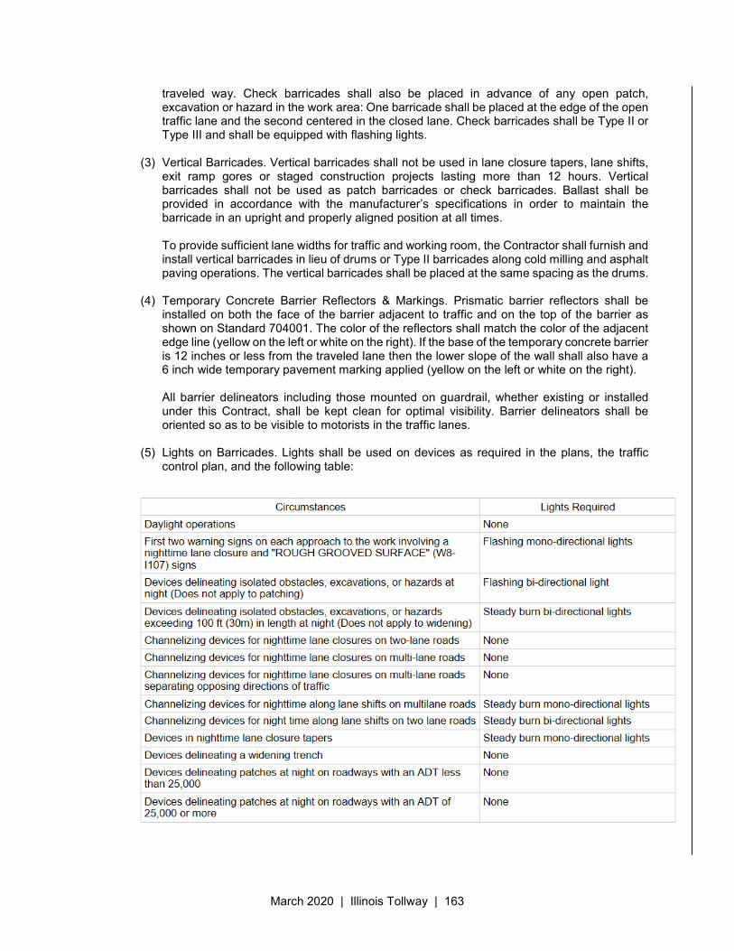
March 2020 | Illinois Tollway | 163
traveled way. Check barricades shall also be placed in advance of any open patch, excavation or hazard in the work area: One barricade shall be placed at the edge of the open traffic lane and the second centered in the closed lane. Check barricades shall be Type II or Type III and shall be equipped with flashing lights.
(3) Vertical Barricades. Vertical barricades shall not be used in lane closure tapers, lane shifts, exit ramp gores or staged construction projects lasting more than 12 hours. Vertical barricades shall not be used as patch barricades or check barricades. Ballast shall be provided in accordance with the manufacturer’s specifications in order to maintain the barricade in an upright and properly aligned position at all times. To provide sufficient lane widths for traffic and working room, the Contractor shall furnish and install vertical barricades in lieu of drums or Type II barricades along cold milling and asphalt paving operations. The vertical barricades shall be placed at the same spacing as the drums.
(4) Temporary Concrete Barrier Reflectors & Markings. Prismatic barrier reflectors shall be installed on both the face of the barrier adjacent to traffic and on the top of the barrier as shown on Standard 704001. The color of the reflectors shall match the color of the adjacent edge line (yellow on the left or white on the right). If the base of the temporary concrete barrier is 12 inches or less from the traveled lane then the lower slope of the wall shall also have a 6 inch wide temporary pavement marking applied (yellow on the left or white on the right). All barrier delineators including those mounted on guardrail, whether existing or installed under this Contract, shall be kept clean for optimal visibility. Barrier delineators shall be oriented so as to be visible to motorists in the traffic lanes.
(5) Lights on Barricades. Lights shall be used on devices as required in the plans, the traffic
control plan, and the following table:
March 2020 | Illinois Tollway | 164
(b) Lanes, Ramps & Gores
(1) Maintain Minimum Lanes. The Contractor shall schedule his construction operations so as to maintain the minimum number of lanes as shown in the Maintenance of Traffic Plans exclusive of acceleration lanes, deceleration lanes, or weaving lanes, in both mainline directions, subject to the conditions specified for each construction stage. Construction scheduling shall also be such as to maintain a single lane of traffic on all ramps.
(2) Short-term Short Ramp Tapers Permitted. The Contractor shall be required to maintain the ramp acceleration and deceleration taper lengths shown in the Plans as a minimum. The Contractor shall be permitted to use shorter lengths for a maximum of three 3 continuous hours with prior written approval of the Engineer.
(3) Use of Gores, Shoulders and Covering of Slotted Drains. During construction, a portion of the existing Illinois Tollway shoulders and gore areas may be used for traffic lanes. When this is necessary, shoulder repairs shall be made as required in order to bring the shoulder to a useable condition. The shoulders shall be repaired at locations noted in the Plans and/or as directed by the Engineer. This work will be measured and paid for in accordance with the provisions of Section 442 of the Standard Specifications. Where shown in the Plans or as directed by Engineer, gore areas shall be temporarily filled to provide a smooth riding surface for use as a traffic lane. Slotted drains shall be securely covered with 0.024" aluminum flashing, 12" wide to prevent intrusion of bituminous material into the pipe. A paper bond breaker shall be used, except at edges, to facilitate removal of such temporary fill when no longer required.
(c) Roadway Maintenance. The Contractors must, during the term of the contract, inspect on a daily basis, repair and maintain all traffic lanes. This includes, but is not limited to, pothole & pavement de-lamination, repair & maintenance and repair of any other pavement defects. Contractors shall coordinate the scheduling of such repairs with the Engineer. This work requires traffic control and will be treated as emergency repairs for the purpose of obtaining any necessary lane closures. The repair and maintenance operations shall be performed within 12 hours of the defect being identified. The contractor shall follow the procedure described in the Illinois Tollway Lane Closure Guide for “Emergency Lane Closure/or After Business Hours Request.” Roadway maintenance work will be paid for according to Article 109.04. After the shoulders are no longer required for traffic lanes, the Contractor will repair shoulder areas as directed by the Engineer: This work shall be measured and paid for in accordance with the provisions of Section 442 of the Standard Specifications.
(d) Altered Conditions & Temporary Lane Closures. It is the intention of the Illinois Tollway to provide consistent stage changing throughout all contracts. In the event of construction changes and with the approval of the Chief Engineering Officer, the Contractor may be allowed to proceed into subsequent stages or continue in a particular stage that may be inconsistent with the traffic flow through adjoining contracts. The implementation of any such deviations and inconsistencies shall be understood to be for the convenience of the Contractor and, unless otherwise specifically agreed in writing between the parties to the Contract, shall be undertaken without additional cost to the Illinois Tollway and without cause for the Contractor claiming delay. Contract specific information regarding Temporary Lane Closures shall be found in the contract special provision, MAINTENANCE OF TRAFFIC. All lane closure requests shall be made by the Contractor in writing and on the appropriate form according to the Illinois Tollway Lane Closure Reference Guide. The Contractor shall submit the request to the Engineer before 7:00 AM on the business day before the closure, i.e:
March 2020 | Illinois Tollway | 165
Tuesday work is due Monday before 7:00 AM Wednesday work is due Tuesday before 7:00 AM Thursday work is due Wednesday before 7:00 AM Friday work is due Thursday before 7:00 AM Saturday, Sunday & Monday work is due Friday before 7:00 AM
Closures shall be in accordance with the Illinois Tollway Traffic Control and Communications Guidelines and the Illinois Tollway Standard Drawing E2, Lane Closure Details.
(e) Intermediate Phase Changes. The Contractor will be allowed one intermediate phase change per direction per stage, subject to the requirements herein specified. An intermediate phase change shall be defined as an interim traffic transition or jog within a stage and shall be implemented with 65:1 taper rates, transition edge lines and transition barricades on 50 foot centers. The location of the shift and the installation of proper signing shall be approved by the Engineer. If a conflict with adjoining Contracts should arise, construction staging as shown in the Plan Typical Sections shall take precedence over any intermediate phase change.
(f) No Work on Both Sides of Live Traffic. Simultaneous work activities on both side of the same direction of Illinois Tollway traffic shall not be allowed. The Contractor shall be subject to a penalty under Article 701.01.08(a) whenever the Contractor or his/her Sub-Contractor is found to be in non-compliance.
(g) Drop Offs. Where construction operations result in a temporary drop-off at the edge of adjacent open traffic lanes where uneven lane conditions, milled edges or other drop-off conditions that occur in the work zone, the Contractor shall be responsible for providing traffic control devices according to the requirements of Section 8.0 of the Roadway Traffic Control and Communications Manual.
(h) Full Expressway Closures. Full Tollway closures will only be permitted during the allowable time frames provided for in Article 701.06. During full Tollway closures, the Contractor will be required to close off all lanes except one using the applicable Tollway Maintenance of Traffic Standards. The Contractor shall initiate the full Tollway closure request using the “10 Day Advance Lane/Shoulder Closure Request” and the “State Trooper Assistance Form” provided in the Illinois Tollway Lane Closure Reference Guide.
(i) Emergency Pull-outs. Emergency pull-out shall be installed at the locations shown on the plans. Emergency pull-out closures will only be allowed when the adjacent lane is closed with a temporary lane closure and during allowable temporary lane closure times. During periods of closure, emergency pull-out signage shall be covered or removed. When an existing emergency pull-out is removed from service for a period beyond the time limit for a temporary lane closure, an alternate emergency pull-out location shall be established within 24 hours. Approval shall be obtained by the Engineer prior to relocating an emergency pull-out. Relocating temporary concrete barrier will be paid for as RELOCATE CONCRETE BARRIER, and the placement, relocation and removal of all other signs, barricades and other items shown on Standard E7 will not be measured for payment.
701.06 - Construction Traffic Operations The Contractor shall be responsible for the proper maintenance of all traffic control devices installed by him including proper location, installation, arrangement, and conditions as designated in the Contract Plans and Special Provisions, or required by the Engineer, for the duration of the Contract. The Contractor shall provide the necessary manpower, vehicles, equipment, and supplies of extra traffic control devices to adequately fulfill this responsibility. As a minimum, the Contractor shall have
March 2020 | Illinois Tollway | 166
a Worksite Traffic Supervisor who will be responsible for initiating, installing and maintaining all traffic control devices including pavement markings as described in this Section and in the plans. The Worksite Traffic Supervisor or his designee shall have at least one year of experience directly related to worksite traffic control in a supervisory or responsible capacity and shall be certified by the American Traffic Safety Services Association Worksite Traffic Supervisor Certification Program or an equal approved by the Illinois Tollway. Approved alternate Worksite Traffic Supervisors may be used when necessary.
(a) Traffic Control Setup and Removal. All lane closure signs shall not be erected any earlier than
one-half (1/2) hour before the starting hours authorized by the Engineer. The signs shall be taken down within one-half (1/2) hour after the closure is removed. Traffic control shall be installed sequentially in the direction of the traffic flow and removed in reverse order. Advance warning signs shall be erected prior to channelizing devices and shall remain until all devices have been removed. The setting and removal of barricades required for lane closures, placement of pavement markings and moving lane closures shall be done under the protection of a vehicle equipped with a truck/trailer-mounted attenuator and arrow board that comply with applicable sections in Article 701.03.
(b) Placement of Barricades. The Contractor will not be permitted to erect, change or remove any barricades or barricade systems without prior approval of the Engineer. The Contractor will be required to leave and maintain all traffic control devices in place until all construction operations have been completed in each stage shown in the Contract Plans. The Contractor shall schedule and conduct his operations so that full access is provided at all interchanges, unless otherwise directed by the Engineer. The Contractor shall arrange and manipulate barricade placement and schedule construction operations to permit continuous operation of all lanes designated as open to traffic, unless otherwise directed by the Engineer. Minor modifications of barricade placement at entrance and exit ramps and at runarounds will be allowed; however, such modifications shall be approved by the Engineer. Barricade placement in connection with such modifications must be consistent with all advance guide or detour signs.
The height of the barricades shall not be less than 3 feet above pavement or shoulder elevation. Barricades that must be placed in excavated or “below-grade” areas shall be equipped with leg extensions to raise the top bar to this minimum height. The cost for furnishing leg extensions where necessary shall be considered as included in the Contract lump sum price for Maintenance of Traffic and no additional compensation will be allowed.
(c) Placement of Cones. The requirements of Article 701.06(a) shall also govern the placement of cones. When dictated by wind or traffic conditions, cones shall be “doubled” or otherwise satisfactorily weighted at their bases to prevent their being blown into the path of vehicles in adjacent open lanes. Placing tires over cones for added stability will not be permitted. If the Contractor is unable to successfully prevent the migration of cones into live traffic lanes, and when so directed by the Engineer, their use shall be discontinued and weighted barricades used in their place.
(d) Placement of Traffic Signs. The Contractor shall be required to cover traffic sign legends which are inconsistent with intended traffic flow patterns. Each cover shall be a blank 1/4" plywood panel bolted to the sign face in such a manner so as to cover the inconsistent message.
All diamond-shaped construction warning signs used on mainline, crossroads and ramps shall be fluorescent orange in color.
March 2020 | Illinois Tollway | 167
(e) Maintenance and Cleaning of Devices. All traffic control equipment shall be kept clean for maximum visibility and shall be cleaned at least weekly if required. The Engineer shall be notified of the equipment cleaning schedule.
(f) Flaggers, Spotters & Truck Mounted Attenuators. All flaggers and spotters engaged in work zone traffic control operations are required to be certified either by IDOT or by an agency approved by IDOT. While on the job site, each flagger and spotter shall have in his/her possession a current driver’s license and a current flagger certification I.D. meeting IDOT requirements. For non-drivers, the Illinois Identification Card issued by the Secretary of State will meet the requirement for a current driver’s license. This flagger certification requirement may be waived by the Engineer for emergency situations that arise due to actions beyond the Contractor’s control where flagging is needed to maintain safe traffic control on a temporary basis. Flaggers and spotters shall be equipped as specified in Articles 701.03 (h) and 701.03(i). A flagger is required 200' in advance of each work area where construction vehicles and trucks are entering or leaving the work site, and at all times during which workers are present where traffic is restricted to less than the normal number of lanes and the workers are not separated from the traffic by physical barriers. “FLAGGER AHEAD” signs will be required in advance of a flagger station (500' on mainline; 200' on ramps) at all times that a flagger is used to control traffic. Such signs shall be removed or covered when the flagger is not present. The longitudinal placement of the flagger may be increased up to 100 ft. from that shown on the plans to improve the visibility of the flagger. Flaggers are not permitted to stop traffic on the Illinois Tollway mainline, and the stoppage of traffic on ramps will not be allowed without the prior approval of the Illinois Tollway Maintenance & Traffic Division. When it is necessary to halt traffic on the Illinois Tollway, District 15 Police are required to assist in this operation. A spotter is defined as a certified flagger that provides support to workers by monitoring traffic in the vicinity of work activities. Except as otherwise shown on the plans, one spotter shall be provided 200’ in advance of each work area where workers are working. Spotters shall be equipped with a loud warning device that shall be identifiable by workers so that evasive action can be taken when necessary. Spotters shall not encroach on the open lane of traffic nor interact with or control the flow of traffic. During nighttime operations, flaggers and spotters shall be illuminated by an overhead light source providing a minimum vertical illuminance of 10 fc measured 1 ft. out from the flagger’s chest. The bottom of any luminaire shall be a minimum of 10 ft. above the pavement. Luminaire(s) shall be shielded to minimize glare to approaching traffic and trespass light to adjoining properties. In work zones with no positive protection, a truck mounted attenuator (TMA) shall be provided to protect workers from an adjacent open traffic lane. A 200’ buffer area between the front of the TMA and workers or equipment shall be provided unless otherwise determined. Where workers or equipment are present beyond the work area, an additional TMA shall be provided for each work area. A work area is defined as starting at the end of the buffer area, extending 1000 feet beyond this point. When a TMA is being provided, the use of a spotter may be eliminated.
(g) Work Above or Below Active Roadways. Any work requiring work to be performed over operational traffic lanes shall be done over only one lane at a time, with that lane being closed to traffic. The Contractor will be required to coordinate such repair operations with the construction staging shown in the Maintenance of Traffic Plans. When any bridge repair or construction operation or feature is likely to cause the vertical clearance over any operational traffic lane(s) to be reduced, the Contractor shall contact both the
March 2020 | Illinois Tollway | 168
Illinois Tollway and the agency of jurisdiction over such operational lanes not less than 10 working days prior to the start of such construction for permission and instructions with respect to signing and Maintenance of Traffic requirements. The cost therefore shall be considered as included in the Contract lump sum price for Maintenance of Traffic.
(h) Erection Work. Procedures to enable erection of any items of work above roadways with vehicular and/or pedestrian traffic shall be subject to the provisions of Articles 504 and 505 of the Standard Specifications and 733 and 734 of the Supplemental Specifications. The Contractor shall submit to the Engineer the erection and maintenance of traffic methods they propose to use. Along with erection drawings, the Contractor shall submit for the Illinois Tollway’s approval a detailed traffic control plan for the erection period. Although specific requirements are dependent upon the Agency(s) whose facility the beams/girders or trusses are to be erected over, the number of lanes, the type of erection equipment used, etc., the following minimum requirements shall be complied with by the Contractor.
(1) Any erection of beams/girders, sign trusses, or monotubes over a Illinois Tollway road shall require a complete closure to traffic, regardless of location or time of day.
(2) The Contractor shall erect beams/girders, sign trusses, or monotubes only between the hours of 12:01 A.M. and 5:00 A.M. Monday through Saturday. 10 day advance written notice to the Illinois Tollway, together with the Engineer’s written approval, will be required prior to erection of any beam/girder and requested in accordance with Section 701.05(h).
(3) The maximum allowable time limit for a full closure on a Illinois Tollway road shall be fifteen (15) minutes, ten (10) minutes for sign truss or monotube erection. For complex erection, demolition activities or other activities requiring longer duration, the Engineer may approve additional time according to the table in the Special Provision, MAINTENANCE OF TRAFFIC.
(4) For any Beam/Girder and truss erection over a non-Illinois Tollway road or facility, written approval from the appropriate Agency shall accompany the submission to the Illinois Tollway for its approval.
(5) The Contractor shall not reopen lanes below newly-erected members until the members are securely in place. In the event the full-width Illinois Tollway closure exceeds the allowable time period, the Contractor will be subject to a penalty cited in Article 701.08(e).
(6) Multiple full expressway closures will be allowed within the hours of 12:01 A.M. and 5:00 A.M. However, the Contractor shall release all stopped traffic prior to implementing subsequent full expressway closures.
(i) Contractor Vehicular & Pedestrian Movements. Except as provided in Article 701.06(b), the Contractor’s vehicles shall move with and not across or against the flow of traffic. These vehicles will not be permitted to make U-turns or cross the median at any location and all vehicles will be required to use local exits and local streets to reverse direction except when both median lanes are closed to traffic. U-turns will be permitted at the existing crossovers shown in the Contract Plans only with the prior approval of the Illinois Tollway and subject to the conditions or constraints concomitant to such approval. Vehicles shall enter or leave work areas in a manner which will not be hazardous to, or interfere with, normal Illinois Tollway traffic. Vehicles shall not park or stop except within designated work areas.
All vehicles including passenger cars, shall be equipped with a yellow high-intensity rotating, flashing, oscillating, or strobe warning light visible on a sunny day from a distance of 1000 feet
March 2020 | Illinois Tollway | 169
to the rear of the vehicle. In addition, a sign must be displayed on each side of the vehicle and with letters at least 3 inches in height and with a suitable font, showing the company identification. Magnetic or temporary signs are acceptable. Parking of personal vehicles within the right-of-way will not be permitted except when specific areas are designated by the Engineer. The Contractor’s personnel will be prohibited from crossing operational lanes on foot. All pedestrian movement on the Illinois Tollway will be limited to within barricaded work areas. Failure by the Contractor’s personnel to comply with these requirements will be considered non-compliance with the Maintenance of Traffic Specifications and shall render the Contractor subject to the applicable penalty cited in Section 701.08.
(j) Maintenance of Traffic at Crossroads. Maintenance of traffic and lane closures on crossroads shall be in accordance with the latest edition of the MUTCD and the requirements of the appropriate jurisdictional agency and as shown in the Maintenance of Traffic plans.
Prior to commencing any work on, adjacent to, or over any crossing roadway, the Contractor shall contact the appropriate agency and shall secure all required permits, as determined by such agency. The Contractor shall supply the Illinois Tollway and the Engineer with copies of all permits. Costs incurred in connection therewith will not be paid for separately, but will be considered as included in the Contract lump sum price for Maintenance of Traffic. When a lane closure is necessary, the Contractor shall notify the agency having jurisdiction at least 48 hours in advance. The Contractor shall furnish, erect and maintain all barricades, cones, temporary pavement markings, traffic control signs and all other fixtures and devices which may be required for the safe movement of traffic on the crossroads.
(k) Traffic Control for Work Zone Areas. Work zone entry and exit openings shall be established as shown in the Maintenance of Traffic plan and be in accordance with Tollway standards. All vehicles shall enter & exit the work zone at the openings. These openings shall be signed in accordance with the details shown in the Contract Documents and shall be under flagger control during work hours. The Contractor shall plan his trucking operations into and out of the work zone as well as onto and off of the expressway to maintain adequate merging distance. Merging distances to cross all lanes of traffic shall be no less than ½ mile in length from where the trucks exist the work zone to where the trucks exist the expressway. The stopping of expressway traffic to allow trucks to change lanes and/or cross the expressway is prohibited. Failure by the Contractor’s personnel to comply with these requirements will be considered non-compliance with the Maintenance of Traffic Specifications and shall render the Contractor subject to the applicable penalty cited in Section 701.08.
(l) Night Time Work Zone Lighting. When the Contractor is permitted by the Contract to perform any work during periods of darkness, the Contractor shall provide and maintain nighttime work zone lighting in accordance with Section 105.17 of the Supplemental Specifications. The existence of general roadway illumination shall not relieve the Contractor of his responsibility for furnishing and maintaining any of the protective facilities hereinafter specified.
(m) Equipment Parking & Material Storage. During working hours, all vehicles and/or non-operating equipment and material stockpiles which are parked or stored for 2 hours or less shall be located at least 8 feet from the edge of the nearest moving traffic lane. During non-working hours, or during working hours for periods of more than 2 hours, all vehicles and/or non-operating equipment and material stockpiles shall be parked or stored outside the “clear zone” or shall be located at least four feet behind man-made or natural barriers which in
March 2020 | Illinois Tollway | 170
the opinion of the Engineer serve to fully shield the storage area and not constitute a hazard to motorists. Temporary concrete barrier sections which are installed in conjunction with lane closures or as shielding for work areas will be considered an acceptable means of shielding of storage areas, subject to approval of the Engineer. When adequate right-of-way does not exist to accommodate this requirement, and when in the opinion of the Engineer no practical alternative exists, the storage area may be located a minimum of 15 feet from the edge of the nearest traffic lane and shall be delineated with barricades and flashing lights at no additional cost to the Illinois Tollway. The Contractor shall protect the stored materials from errant vehicles with an approved means of protection also at no additional cost to the Illinois Tollway. With the exception of the special condition with respect to 2 hour periods, no parked Contractor vehicles, non-operating equipment, or material stockpiles will be allowed to remain closer than 15 feet to any operational traffic lane under any circumstances. Failure by the Contractor to comply with these requirements will be considered non-compliance with the Maintenance of Traffic Specifications and shall render the Contractor subject to the applicable penalty cited in Section 701.08.
701.07 - Holiday Periods No work which will require movement of vehicles to and from the work site or which will otherwise interfere with Illinois Tollway traffic will be allowed during the following holiday periods without specific written authorization from the Illinois Tollway:
Easter Weekend - 12:00 Noon Thursday through 9:00 A.M. Monday Memorial Day Weekend - 12:00 Noon Friday through 9:00 A.M. Tuesday Independence Day - as specified in the Special Provisions Labor Day Weekend - 12:00 Noon Friday through 9:00 A.M. Tuesday Thanksgiving Weekend -12:00 Noon Wednesday through 9:00 A.M. Monday Christmas-New Year’s Day period - as specified in the Special Provisions
701.08 Penalties
(a) Non-Compliance with Specifications. The Contractor will be subject to a penalty of $2,500.00, per incident per day, to be deducted from the next pay estimate due the Contractor, for each occurrence when the Engineer determines that the Contractor or his Subcontractor is not in full compliance with the Maintenance of Traffic Specifications.
(b) Failure to Respond. The Contractor shall be required to respond within 1/2 hour to any request from the Engineer for re-aligning, replacing or moving traffic control devices or temporary concrete barrier, or otherwise re-establishing compliance with the Maintenance of Traffic Specifications. “Respond” is interpreted to mean on the job preparing to make repairs. Failure by the Contractor to so respond shall be grounds for a penalty of $2,500.00, for each and every occurrence, to be deducted from the next pay estimate due the Contractor. In addition, if the Contractor fails to respond, the Engineer may correct the deficiencies and the cost thereof will be deducted from monies due or which may become due the Contractor. This corrective action will in no way relieve the Contractor of his/her contractual requirements or responsibilities.
March 2020 | Illinois Tollway | 171
(c) Failure to Repair Impact Attenuators. If during the term of the Contract, any Impact Attenuators, Temporary furnished and installed by the Contractor is damaged or displaced by any cause or event, the Contractor shall be responsible for repairing, replacing and/or realigning the component modules and restoring the system to the intended configuration. The Contractor shall complete all such necessary system restoration within 24 hours of notification by the Engineer. Failure to comply with this requirement shall be grounds for a daily penalty of $2,500.00 for each day or portion thereof (after the initial 24 hour period) that the directed restoration remains incomplete, to be deducted from the next pay estimate due the Contractor.
(d) Loss or Damage to ISTHA-Owned Devices. The Contractor will be required to remove all traffic control devices furnished by the Illinois Tollway which are installed and maintained by him under the contract and deliver them to the Illinois Tollway’s Sign Shop in Naperville, IL. All such traffic control devices shall remain in place until specific authorization to relocate the traffic control devices is received from the Engineer for stage changes or modifications of lane closures. The cost of any Illinois Tollway-owned signs damaged beyond re-use or lost due to the Contractor’s negligence will be deducted from the monies due the Contractor under the item Maintenance of Traffic pay item at the rate of $100.00 per square foot of sign so lost or damaged or the sign shall be replaced in-kind.
(e) Failure to Open Traffic Lanes to Traffic. Should the Contractor fail to completely open and keep open all of the traffic lanes to traffic, the Contractor will be subject to a penalty as follows:
a. One lane or ramp blocked = $3,000.00 / 15 minutes b. Two lanes blocked = $5,000.00 / 15 minutes
The penalty shall be assessed for each and every 15 minute interval or portion thereof that a lane is blocked outside the allowable time limitations.
701.09 - Method of Measurement & Basis of Payment
Work zone traffic control and protection will be measured and paid for as MAINTENANCE OF TRAFFIC. MAINTENANCE OF TRAFFIC will be measured on a lump sum basis and paid for at the Contract lump sum price, which payment shall constitute full compensation for all labor, equipment, materials and incidentals necessary to furnish, install, maintain, clean, relocate, and remove all traffic control devices, including but not limited to barricades, cones, standard signs, warning lights, arrow boards, truck mounted attenuators, all traffic channelization required for temporary and permanent pavement marking, for furnishing and equipping flaggers & spotters, and for complying in all respects with the requirements of the Contract for the safe and expeditious movement of vehicular traffic through the zones of construction.
Payment for this work will be made in the following manner:
(a) Upon furnishing and installing equipment and materials for the first major stage of construction, 25% of this pay item will be paid.
(b) The remaining 75% will be pro-rated over the remaining contract period and paid in monthly installments.
Non-standard signs shall be paid for according to the Special Provision TEMPORARY INFORMATION SIGNING. Temporary shifting of existing guide signs will be paid for as RELOCATE SIGN PANEL of the type specified.
March 2020 | Illinois Tollway | 172
Furnishing, placing, maintaining, repairing, and removing temporary concrete barrier will be paid for separately according to the Special Provision TEMPORARY CONCRETE BARRIER.
Work zone traffic control and protection at locations not under the jurisdiction of the Illinois Tollway except for permits, will be paid for separately.
March 2020 | Illinois Tollway | 173
Illinois State Toll Highway Authority
SUPPLEMENTAL SPECIFICATION FOR
SECTION 725. TERMINAL MARKER
Issued March 23, 2020 This Supplemental Specification amends and supersedes the provisions of the Illinois Department of
Transportation Standard Specifications for Road and Bridge Construction, adopted April 1, 2016 and shall be construed to be a part thereof, superseding any conflicting provisions thereof applicable to the work under the contract.
This modifies Section 725 as follows:
725.01 Description. This work shall consist of furnishing and installing direct applied terminal markers on guardrail terminals and impact attenuators in accordance with manufacturer’s specifications for the terminals and attenuators.
725.02 Materials. Materials shall be according to Section 1091 of the Standard Specifications.
CONSTRUCTION REQUIREMENTS
725.04(a) Direct applied terminal markers shall be installed directly on the end of the guardrail terminal as shown on the plans and IDOT Highway Standard 725001. Impact attenuators shall have a terminal marker direct applied to their nose according to the manufacturer’s specifications. The surface of the terminal shall be cleaned of all contaminants prior to the installation of the terminal marker. The surface shall be cleaned using a 5-8 percent phosphoric acid solution and rinsed with clean water; or cleaned per the terminal marker sheeting manufacturer’s specifications.
725.05 Method of Measurement. This work will be measured in units of each.
726.06 Basis of Payment. This work will be paid for at the contract unit price per each for TERMINAL MARKER – DIRECT APPLIED.
March 2020 | Illinois Tollway | 174
Illinois State Toll Highway Authority
SUPPLEMENTAL SPECIFICATION FOR
SECTION 726. MILEPOST MARKER INSTALLATION AND ASSEMBLY
Issued March 23, 2020 This Supplemental Specification amends and supersedes the provisions of the Illinois Department of
Transportation Standard Specifications for Road and Bridge Construction, adopted April 1, 2016 and shall be construed to be a part thereof, superseding any conflicting provisions thereof applicable to the work under the contract.
Section 726 of the Standard Specifications is replaced with the following:
726.01 Description. This work shall consist of the following: Loading milepost marker panels fabricated by the Illinois Tollway at the Illinois Tollway’s Sign Shop in Naperville, Illinois, transporting them to the job site and mounting them on telescoping steel posts ground mounted or barrier wall mounted and/or attaching them to light pole or sign structures as shown in the plans using the required mounting hardware. Furnishing and installing a milepost marker assembly at a location specified in the plans for milepost marker panels furnished by the Illinois Tollway or the Contractor.
726.02 Materials. Materials shall be according to the following provisions of the Standard Specifications: Item Article
(a) Metal Posts and Hardware for Highway markers, Signs and Delineators (Note 1) ................................................................. 1006.29
Note 1. Posts for milepost markers shall be galvanized, 12 gauge steel posts. Hardware for milepost markers shall be zinc coated unless otherwise indicated on the plans.
726.03 Construction Methods. New sign panels included with this provision will be fabricated by the Illinois Tollway’s sign shop in Naperville, Illinois. The Contractor shall obtain and load the signs on his hauling units at the sign shop and transport them to the various erection sites. The Contractor shall exercise due care in handling the sign panels during all phases of this operation. Any sign that is damaged due to the Contractor’s handling or operations shall be repaired by the Contractor to the satisfaction of the Engineer, at no additional cost to the Illinois Tollway, and without cause for the Contractor claiming delay. Any sign panel that is lost or damaged beyond use shall be replaced by the Contractor at no additional cost to the Illinois Tollway and without cause for the Contractor claiming delay. The installation shall be as shown on the Illinois Tollway Standard Drawing F11. The assembly shall be installed using all required mounting hardware.
726.04 Method of Measurement. When supplied by the Illinois Tollway, The work for MILEPOST MARKER INSTALLATION will be measured for payment per square feet. Sign panel will be
March 2020 | Illinois Tollway | 175
measured in square feet according to Article 720.06 of the Standard Specifications when supplied by the Contractor. Milepost Marker Assemblies will be measured in units of each.
726.05 Basis of Payment. When Tollway supplied, sign installation will be paid for at the Contract unit price per square foot for MILEPOST MARKER INSTALLATION. When the Contractor supplies the sign panel, sign installation will be paid for at the contract unit price per square foot for SIGN PANEL, TYPE 1 according to Article 720.07 of the Standard Specifications. Milepost marker assemblies will be paid for at the Contract unit price per each for MILEPOST MARKERS ASSEMBLY, GROUND MOUNTED; MILEPOST MARKERS ASSEMBLY, BARRIER WALL MOUNTED; or MILEPOST MARKERS ASSEMBLY, POLE MOUNTED.
March 2020 | Illinois Tollway | 176
Illinois State Toll Highway Authority
SUPPLEMENTAL SPECIFICATION FOR
SECTION 727. SIGN SUPPORT - BREAKAWAY
Issued April 5, 2019 This Supplemental Specification amends and supersedes the provisions of the Illinois Department of
Transportation Standard Specifications for Road and Bridge Construction, adopted April 1, 2016 and shall be construed to be a part thereof, superseding any conflicting provisions thereof applicable to the work under the contract.
Modify the following Article. 727.07 Method of Measurement. Replace the second paragraph with the following: The measurement of the structural steel shall be computed on the basis of the stub weight listed
on Illinois Tollway Standard F9 and the weight per foot of the support multiplied by the length of the main posts.
March 2020 | Illinois Tollway | 177
Illinois State Toll Highway Authority
SUPPLEMENTAL SPECIFICATION FOR
SECTION 733. OVERHEAD SIGN STRUCTURES
Issued April 1, 2016 Revised March 23, 2020
This Supplemental Specification amends and supersedes the provisions of the Illinois Department of Transportation Standard Specifications for Road and Bridge Construction, adopted April 1, 2016 and shall be construed to be a part thereof, superseding any conflicting provisions thereof applicable to the work under the contract.
Delete Section 733 of the Standard Specifications in its entirety and replace with the following. 733.01 Description. This work shall consist of fabricating, furnishing, and erecting span, cantilever,
butterfly, monotube or bridge mounted type overhead sign structures, including supports, on previously prepared foundations conforming to the details and locations shown in the Plans.
733.02 Materials. Materials used in the fabrication of the overhead sign structures shall conform to the requirements shown in the Plans and to the following:
(a) Structural Steel Pipe: All structural steel pipe shall conform to the ASTM A53, Type E or S, Grade B, API 5L Grade B or Grade X42 or Grade X52; ASTM A106, Grade B.
(b) Steel Plates: Steel plates shall conform to the requirements of ASTM A36 (AASHTO M183) or ASTM A572 Grade 50, as specified in the drawings
(c) Structural Steel Tube: All structural steel tube shall conform to ASTM A500, Grade B.
(d) High-Strength Steel Bolts: High-strength bolts shall conform to ASTM A325 Type 1 (AASHTO M164).
(e) Washers: Washers shall conform to ASTM F436 (AASHTO M293).
(f) Stainless Steel Bolts: All stainless-steel bolts shall conform to the ASTM A193, Class I, Grade B8 (AISI Type 304).
(g) Stainless Steel Nuts: Stainless steel nuts shall conform to ASTM A194 (AASHTO M292), Grade 8F (AISI Type 303), unless noted otherwise. Stainless steel nuts for high-strength steel bolts and high-strength anchor bolts shall conform to the requirements of ASTM A194, Grade 2H. The nuts shall be “locknuts” and shall be equivalent to the finished hex series of the American Heavy Standard Series.
(h) Nuts: Nuts for high-strength steel bolts and high-strength anchor bolts shall conform to the requirements of ASTM A563 (AASHTO M291), Grade DH.
(i) Stainless Steel Washer: Unless noted otherwise, stainless steel washers shall conform to ASTM A240, Type 302.
(j) Aluminum Tubes for chords and diagonals shall conform to ASTM B221, Alloy 6061-T6.
March 2020 | Illinois Tollway | 178
(k) Aluminum Flange Plates for splices shall conform to ASTM B209, Alloy 6061T651 or ASTM B221, Alloy 6061-T6.
(l) Aluminum Alloy castings shall conform to ASTM B26, Alloy 356 and forgings shall conform to ASTM B247, Alloy 6061-T6.
(m) Aluminum plates shall conform to ASTM B209, Alloy 6061-T651 or Alloy 6061T6.
(n) High-Strength Anchor Bolts shall conform to ASTM F1554 (AASHTO M314) Grade 55 or Grade 105 as noted on the plans.
(o) Neoprene Pads: Neoprene pads shall be of the size shown in the Plans and shall have a Shore Durometer surface hardness of 65.
(p) Stainless Steel Band and Wire Mesh Cloth: The stainless-steel band and stainless steel wire mesh cloth shall conform to ASTM A276 Type 304L, and ASTM E2016 normal weave.
733.03 Drawings. Article 505.03 of the Standard Specifications shall govern.
733.04 Fabrication.
(a) Structural Steel: Article 505.04 of the Standard Specifications shall govern.
(b) Structural Aluminum: Article 733.04 shall govern, except as modified by the following:
(1) General: Aluminum materials shall be sawed or milled. Flame cutting will not be permitted. Holes in extruded material shall be drilled. Holes in forgings shall be drilled, or formed and reamed for final fit. In handling aluminum materials in the shop and in the field, every precaution shall be taken to avoid scoring or marring of the surfaces, sufficient in the opinion of the Engineer, to cause an objectionable appearance. Such scoring or marring shall be cause for rejection of the material. Cast or forged parts shall have all fins or other irregularities removed. Tubing shall be seamless and uniform in quality and temper. Exterior and interior surfaces shall be clean, smooth and free from seams, slivers, laminations, grooves, cracks, or other defects.
(2) Welding: Welding shall be done by the inert gas shielded arc method and no flux shall be used. Welders shall qualify by passing the requirements of Procedure and Performance Test of Qualification Standard for Welding Procedure for Welders and Welding Operators, current edition, formulated by the Boiler and Pressure Vessel Committee of ASME.
Qualifications shall be based on welding of aluminum alloy 6061-T6 with consumable electrode type welding, using the same aluminum alloy filler material specified herein. Welding shall comply with the Specifications mentioned in Section I, Fabrication, of ASCE Paper 970, Specifications for Structures of Aluminum Alloy 6061-T6. Welding shall be carefully checked by the fabricator by visual inspection of all welds, by proof testing of welds, and by the destructive testing of weld samples fabricated during the production welding. Poor welding workmanship as noted by visual inspection shall be sufficient cause for rejection.
All welds shall be made in accordance with current AWS Specifications. Aluminum alloy filler metal for welding aluminum shall conform to Specification for Aluminum and Aluminum Alloy Welding Rods and Electrodes, AWS A5.10-88 or latest edition.
Fillet sizes for welding on aluminum members shall be at least as thick as the thinnest member being welded.
March 2020 | Illinois Tollway | 179
733.05 Erection
(a) General: Erection of all structural steel and structural aluminum sign trusses shall conform to the applicable provisions of Article 505.08 of the Standard Specifications and the following requirements:
(1) Prior to the erection of the truss, the end supports with their welded base plates shall be mounted over the anchor bolts on the concrete foundations, partially plumbed, and temporarily secured. After the erection of the truss and while the truss is supported by the crane, the uprights shall be fully plumbed and brought to final alignment by means of leveling nuts on the anchor bolts. The top nuts shall then be tightened
(2) All bolts used for assembling truss sections shall be tightened to the tension specified in the Plan erection details and/or indicated in the approved shop drawings. Bolt tension shall be measured in foot-pounds of applied torque.
(3) When air-driven impact wrenches are used to provide the specified bolt tension, they shall be set to provide tension in excess of that specified by not more than 5%. Such wrenches shall be calibrated for each size of bolt to be installed. Calibration shall be accomplished by use of a device providing a direct read-out in foot-pounds of torque on three typical bolts of each size from the bolts to be installed.
The average of the three calibration torque readings shall be used to adjust the impact wrenches for tightening all the bolts of each size.
Wrenches to be used for inspection shall be likewise calibrated. Typical bolts used for testing the calibrations shall be of the same grade, size and condition as those under inspection. Bolts which have been tightened in the truss shall be inspected by applying a calibrated and approved inspection torque wrench to 15% of the bolts, but not less than one bolt selected at random in each connection. If any nut or bolt head is turned by the application of the inspection wrench, all bolts in that connection shall be inspected for proper tightening.
(4) After erection is completed the truss shall be in a true horizontal position, and normal to the pavement centerline.
(5) The Contractor shall verify that the substructure is within allowable tolerances for lines and elevations, properly finished, and anchor rods are set in the correct pattern and orientation, are the correct size, and are plumb with the specified extension and thread length above the top of concrete.
(6) Trusses, Monotubes and support structures shall not be placed on the foundation until concrete foundation including the pile caps has reached 100 percent of the characteristic 28-day strength and 14 days age.
(b) Lane Closure. Lane closures shall be in accordance with the Contract Maintenance of Traffic Special Provision.
(c) Full Span Trusses. The erection and maintenance of traffic procedure for overhead sign trusses shall be as follows, and shall be in accordance with the Special Provisions and applicable provisions of Section 701, unless otherwise authorized by the Illinois Tollway.
(1) The Contractor shall erect the trusses in accordance with the time frames specified in Article 701.06 (h) of the Supplemental Specifications.
March 2020 | Illinois Tollway | 180
(2) All signs, lighting conduit, and other appurtenances shall be attached to each truss prior to erection.
(3) The appropriate lane closure shall be in place, restricting traffic to a single lane of travel, prior to any erection activity.
(4) Closed lanes and shoulders may be used by the Contractor to attach the truss to the lines of the erecting crane.
(5) When the truss is properly balanced for erection, a complete closure to traffic will be required. Traffic shall not be stopped more than ten (10) minutes at any one time.
(6) The lifting crane shall then swing the truss to the end supports. The end supports shall be plumbed and the nuts on the anchor bolts tightened.
(7) One U-Bolt on each end of the truss shall be installed to attach the truss to the end supports.
(8) The erecting lines shall then be detached from the truss and traffic allowed to travel in the single lane until the crane is removed from the pavement.
(9) Traffic may be allowed to drive under the truss in the open lane while the remaining U-Bolts are installed.
(10) The lane closure signs and barricades shall be removed prior to expiration of the allowable lane closure period.
(d) Cantilever Trusses. The provisions of Article 733.05 (c) shall apply, except as modified by the following:
(1) The Contractor may erect cantilever trusses during those hours that one lane traffic closures are permitted under the Special Provisions and/or Section 701.
(2) Item 2 of Article 733.05 (c) shall apply.
(3) Lane closures for the erection of cantilever trusses shall be in accordance with the Contract Maintenance of Traffic Special Provision.
(4) Item 4 of Article 733.05 (c) shall apply.
(5) Traffic shall not be stopped for the erection of cantilever trusses in any lanes other than the lanes authorized for closure.
(6) Item 6 of Article 733.05 (b) shall apply.
(7) Items 7, 8, 9 of Article 733.05 (c) shall not apply. The installation of bolts and other attachment devices shall be as required in the Plan details for each particular design and type of cantilever to be erected.
(8) Item 10 of Article 733.05 (c) shall apply.
(e) Bridge Mounted Sign Support
(1) The applicable provisions of Article 733.05 (b) shall govern.
March 2020 | Illinois Tollway | 181
(f) Butterfly Trusses. The applicable provisions of Article 733.05 (d) shall apply.
(g) Monotube Frames. The erection and maintenance of traffic procedure for overhead monotube frames shall be as follows, and shall be in accordance with the Special Provisions and applicable provisions of Section 701, unless otherwise authorized by the Illinois Tollway.
(1) The Contractor shall erect the monotube frames in accordance with the time frames specified in Article 701.06 (h) of the Supplemental Specifications.
(2) The contractor may install signs, support pipes, antennas, cameras and other appurtenances after erecting the monotube frame.
(3) Lane closures for the erection of monotube frames shall be in accordance with the Contract Maintenance of Traffic Special Provision.
(4) Closed lanes and shoulders may be used by the Contractor to erect the monotube frames.
(5) The installation of bolts and other attachment devices shall be as required in the Plan details for each particular design and type of frame to be erected.
(6) Item 10 of Article 733.05 (c) shall apply.
733.06 Mounting of Bridge Mounted Sign Support
(a) Concrete Girder Structure. Holes to be drilled in structural concrete for mounting sign supports shall be made in a manner which will not damage the concrete and which meets the approval of the Engineer. The positions of the brackets as shown in the Plans are based on the positions of the prestressing strands and the reinforcing steel in the girders as shown in record Plans. Copies of the as-built Plans and shop drawings are available to the Contractor from the Illinois Tollway upon request. Care shall be taken in drilling to avoid drilling through reinforcing steel or prestressing strands. At the first sign of steel cuttings in any drill hole, the drilling shall be stopped and an evaluation made of the conditions relative to the record Plans. Adjustments to the location of the drill holes shall be made to allow drilling to miss the steel. Any such adjustments in hole locations must be approved by the Engineer.
(b) Steel Structure. Holes to be drilled in the steel fascia beam shall be as shown on the Plans and in accordance with the applicable portions of Article 505.04 (d) of the Standard Specifications.
733.07 Galvanizing Steel Structures. After fabrication and drilling of all holes in the horizontal steel truss units, vertical end supports, and bridge mount supports they shall be hot dipped galvanized in accordance with ASTM A123 (AASHTO M111) and ASTM A 385.
The fabricator shall provide relief holes for galvanizing as required by the galvanizer. The location of the holes shall have the approval of the Engineer.
Poor appearance or damage to the galvanized surfaces shall be sufficient cause for rejection.
If, in the judgment of the Engineer, damage or defacement is minor, it shall be repaired with zinc in accordance with American Welding Society “Recommended Practice for Metalizing”, para. C2.2-52T, Part IB.
Hot dip galvanized fasteners, anchor bolts, nuts and washers according to ASTM A123 (AASHTO M111) or ASTM A153 (AASHTO M232) as appropriate to the product; except stainless steel fasteners, nuts and washers.
March 2020 | Illinois Tollway | 182
733.08 Wire Cloth. The void between the base plate and the foundation shall be enclosed according to the following requirements.
A stainless steel mesh 1/4 in. maximum opening with a minimum wire diameter of AWG No. 16 with a minimum 2 in. lap shall be installed to enclose the void between the base plate and the foundation. The stainless steel screen wire shall be formed to the shape of the base plate and fastened to the base plate with 3/4 in. stainless steel banding. The screen wire shall overlap and be fastened with a ring type connection.
733.09 Dampers. Dampers shall be Stockbridge type dampers with the number, size, weight and locations as shown on the plans.
733.10 Method of Measurement
(a) OVERHEAD SIGN STRUCTURE for each of the various types will be measured for payment in feet from center to center of the end supports or from the end of the unsupported end to center of the support as shown in the Plans.
(b) BRIDGE MOUNTED SIGN SUPPORT of each type will be measured in feet, complete, in place and accepted. Such measurement shall be the overall length end to end of the sign panels.
(c) SIGN STRUCTURE WALKWAY. The sign structure walkway will be measured for payment in feet of the overall length of the walkway, end to end.
733.11 Basis of Payment. Payment for OVERHEAD SIGN STRUCTURE, SPAN TYPE (STEEL); OVERHEAD SIGN STRUCTURE, CANTILEVER TYPE (STEEL); OVERHEAD SIGN STRUCTURE, MAINLINE ENTRANCE MONOTUBE TYPE (STEEL); OVERHEAD SIGN STRUCTURE, MAINLINE EXIT MONOTUBE TYPE (STEEL); OVERHEAD SIGN STRUCTURE, AET RAMP ENTRANCE MONOTUBE TYPE (STEEL); OVERHEAD SIGN STRUCTURE, AET RAMP EXIT MONOTUBE TYPE (STEEL); OVERHEAD SIGN STRUCTURE, CASH-IPO RAMP MONOTUBE TYPE (STEEL) and OVERHEAD SIGN STRUCTURE, SPAN TYPE (ALUMINUM), of the depth and width shown in the Plans, will be made at the Contract unit price per foot, complete and accepted, and measured as specified, which payment shall constitute full compensation for furnishing all materials; fabricating and erecting the structures; including the end supports; dampers; galvanizing; and for all labor, equipment, tools and incidentals necessary to complete the work as specified, exclusive of foundations and anchor bolts.
Payment for BRIDGE (CONCRETE) MOUNTED SIGN SUPPORT, BRIDGE (STEEL) MOUNTED SIGN SUPPORT will be made at the Contract unit price per foot, measured as specified, which payment shall constitute full compensation for furnishing all materials; fabricating, erecting and mounting sign sup-ports, including all brackets and hardware; drilling as required; maintenance of traffic; and for furnishing all labor, equipment, tools and incidentals necessary to complete the work as specified.
Payment for SIGN STRUCTURE WALKWAY will be made at the Contract unit price per foot, measured as specified, which payment shall constitute full compensation for furnishing all materials; fabricating, galvanizing and installing the walkway, including all brackets and hardware; drilling as required; and for furnishing all labor, equipment, tools and incidentals necessary to complete the work as specified.
March 2020 | Illinois Tollway | 183
Illinois State Toll Highway Authority
SUPPLEMENTAL SPECIFICATION FOR
SECTION 734. CONCRETE FOUNDATIONS FOR SIGN STRUCTURES
Issued April 1, 2016 Revised April 5, 2019
This Supplemental Specification amends and supersedes the provisions of the Illinois Department of Transportation Standard Specifications for Road and Bridge Construction, adopted April 1, 2016 and shall be construed to be a part thereof, superseding any conflicting provisions thereof applicable to the work under the contract.
Section 734 of the Standard Specifications for Road and Bridge Construction, adopted April 1, 2016
shall be modified as follows:
Replace third paragraph of Article 734.03 with the following paragraph:
The anchor rods shall be firmly held in position utilizing a positioning plate and temporary nuts or other Engineer approved methods to maintain anchor bolts’ alignment during concrete placement.
Add the following to Article 734.03:
(d) Contractor’s Responsibility for Underground Facilities. It shall be the Contractor’s responsibility to ascertain in advance of any work, by any and all possible means, the presence of underground electrical or telecommunications cables in or near the vicinity of the work. It shall be the Contractor’s further responsibility to notify the Illinois Tollway at least ten days in advance of setting new posts when working near underground electrical or telecommunications cables. Illinois Tollway technicians will then locate any such cables which may be in jeopardy. It shall be the Contractor’s responsibility to preserve cable location markings and all information given to him relating thereto, and to effectively communicate such information to his workers. If the Contractor cuts or damages any such cables, either through carelessness or failure to follow the foregoing procedures, he will then be held responsible for repairing all damages or replacing the cable without splicing, at the Illinois Tollway’s option, all at no cost to the Illinois Tollway and without cause for the Contractor claiming delay.
Such repair or replacement shall include the immediate installation by the Contractor, without further notice to him, of temporary cables satisfactory to the Illinois Tollway, the temporary cables to remain in service until the directed repairs or replacements are made. Stringing temporary cables on the ground will not be allowed in any circumstances. Temporary cables shall be:
(1) Suitable for direct burial installation, acceptable to the Illinois Tollway, and shall be buried to a depth not less than 12 inches;
(2) Weather-proof cable, acceptable to the Illinois Tollway, and shall be suspended not less than 8 feet above the highest point of terrain between supports. Suspended temporary cables may be attached to existing poles, or, in their absence, shall be attached to supports acceptable to the Engineer, furnished and installed by the Contractor.
All efforts on the Illinois Tollway’s part to advise the Contractor as to the locations of underground cables notwithstanding, it shall be understood that such locations are at best approximate, may be in error, and that such efforts by the Illinois Tollway shall not relieve the Contractor of any responsibility for restoring damage resulting from the activities of any
March 2020 | Illinois Tollway | 184
employee, sub-contractor, agent, or representative of the Contractor.
It shall be the further responsibility of the Contractor to determine the location of any underground drainage structures, or other utility lines in the vicinity before beginning any work, and to conduct the work so as to avoid damage to any such installation. The Contractor shall contact the Engineer for assistance in locating utilities, drainage structures, and other underground facilities. Any damage caused by the Contractor’s operations shall be immediately repaired by the Contractor, at no additional cost to the Illinois Tollway, and to the satisfaction of the Illinois Tollway.
(e) When any sign structure foundation is to be constructed in a closed roadway median or pavement gore, any existing median barrier wall and base, gutter, or pavement shall be removed and, upon completion of the foundation, made contiguous with the foundation as shown in the Plan details. Any existing underlying subbase and base shall be duplicated in kind in the foundation backfill to preserve the contiguity of such strata. Also, any existing subsurface drainage conduits, sewers, water pipes, utilities, etc. shall be preserved and made continuous through or around the founda-tion. All such work shall be carried out in accordance with the Plan details and/or as directed by the Engineer. The cost for all such removals, replacements, preservation and backfilling, including the cost of furnishing and placing any and all required materials, shall be considered as included in the Contract unit price(s) for Foundation for Overhead Sign Structure.
If the Contractor is unable for any reason to complete any foundation before the onset of the winter season, any open excavation shall be backfilled as directed by the Engineer. The cost thereof shall be considered as included in the Contract unit price(s) for Foundation for Overhead Sign Structure.
Coated Steel Conduit shall be installed in the foundation of each overhead sign structure as shown in the Plans. The conduit shall be anchored securely in place, cleaned and plugged immediately after installation (prior to placement of any concrete).
(f) Foundations for overhead sign structures include:
(1) Span type shoulder and median foundation consists of shoulder or median barrier, any barrier slab as needed, and concrete grade beam supported by drilled shafts. Concrete shall be the Class indicated in the Plans.
(2) Monotube type single face and median foundation consists of shoulder or median barrier, and barrier slab, supported by a drilled shaft. Concrete shall be the Class indicated in the Plans.
(3) Cantilever type foundation consists of concrete column, grade beam supported by a drilled shaft, and crashwall as shown on the plans. Concrete shall be the Class indicated in the Plans.
(4) Butterfly type foundation consists of concrete column and crashwall supported by a drilled
shaft. Concrete shall be the Class indicated in the Plans.
(5) ITS Gantry Frame type shoulder and median foundation consists of shoulder or median crashwall, and concrete grade beam supported by drilled shafts. Concrete shall be the Class indicated in the Plans.
(g) The butterfly type and cantilever type concrete column shall be finished according to conform to
Article 503.15(b) “Rubbed Finish” of the Standard Specifications, followed by concrete sealer application. All other concrete surfaces above the lowest elevation 6 in. below finished ground line shall be finished according to Article 503.15(a) followed by a concrete sealer application.
March 2020 | Illinois Tollway | 185
(h) Site Grounding
All sign structures shall be provided with a site grounding electrode system to provide a single ground reference. This grounding electrode system shall consist of ground rods oriented around the structural foundation of the sign structure as shown on the plans (grounding halo). The grounds rods within the grounding halo shall be connected to each other by a solid continuous 1/C No. 2/0 AWG bare tinned-copper conductor. Where a span type sign structure is specified, a grounding halo shall be provided oriented around each structural foundation as shown on the plans. All ground rods located below the roadway shoulder shall be installed such that the top of the ground rod is a minimum of 30 inches below top of pavement or at the frost line, whichever is deeper. Ground rods located in unpaved (grassy) areas or beneath paved areas (with exception of roadway and shoulder pavement) shall be installed such that the top of the ground rod is a
minimum 12 inches below finished grade and be accessible from within an access well. Whenever possible, ground rods shall be installed a nominal distance of 1.1 times the length of a rod and a minimum of 36 inches from all foundations or other underground structures. In no case shall a ground rod be installed through a foundation or beneath travelled roadway pavement. Whenever possible, the spacing between adjacent ground rods shall be 2 times the length of the ground rod and a minimum of 6 feet in any direction. If the measured resistance to ground exceeds 5 ohms, the Contractor shall install additional ground rods and solid continuous 1/C No. 2/0 AWG bare tinned-copper conductors in an expanding star-burst pattern until the resistance is brought down to acceptable levels. Any additional ground rods and conductors required to reduce resistance to ground to 5 ohms or less shall be incidental to this work. No more than three grounding electrode conductors shall be connected to a single ground rod. Material Requirements: All materials and work shall be in accordance with Article 250 of the latest revision of the National Electrical Code (NEC). All grounding materials shall be listed for the intended application. Ground rods and access wells shall be per Section 806.
Aluminum or copper-clad aluminum grounding conductors SHALL NOT be used.
All grounding electrode conductors shall be a 1/C, solid, soft drawn, tinned-copper unless otherwise specified herein.
All conductors for the bonding of metallic members either attached to the structure and/or those which comprise the sign structure shall be a braided tinned-copper bonding jumper. All bare copper conductors must be tinned. All copper used for lightning protection or equipment bonding must have 95% conductivity when annealed. See Standard Specifications Article 1066.03(b) for additional requirements. All grounding hardware must be stainless steel or galvanized rigid steel. (See installation requirements pertaining to dissimilar metals.)
March 2020 | Illinois Tollway | 186
Unless otherwise noted bus bars (if specified) must be solid copper and be equipped with insulating mounting supports. Bus bars must be pre-drilled with holes suitably sized for terminating up to No. 2/0 AWG grounding conductors with two-hole lugs. General Installation Requirements: All metallic members either attached to the sign structure and those which comprise the structure shall be bonded together by means of a copper bonding jumper as specified herein to create a continuous low impedance path to the site grounding electrode system.
If so equipped, all metallic housings containing electrically energized components or metallic structures which may become energized under fault conditions shall be bonded to the site grounding electrode system.
All grounded metal objects within 25 feet of a component of the sign structure site must be tied into the site grounding electrode system. All connections to structural steel shall be made above grade and external to the structural foundation. In no case shall a conductor connected to the site grounding system pass through a structural foundation. The conductor shall be routed through conduit attached to the structural foundation from a point below grade up to an elevation equal to the top of the structural foundation, as indicated in the Plans, or as indicated on the Plans for foundations located beyond the edge of pavement. For installations with the structural foundation located adjacent to or integral with the median barrier wall, the conductor shall be routed through a conduit installed embedded within the median barrier wall outside the limits of the structural foundation. All equipment bonds must be made to bare metal surfaces as specified herein. All ground rods shall include a ground test well (access well) to allow inspection of connections to the ground rod. Exothermic welded joints on galvanized material shall be coated as specified herein to prevent corrosion.
Copper/Aluminum joints shall be avoided wherever possible. In cases where this cannot be avoided, the connections shall be as specified herein.
Bare copper shall not come in contact with galvanized steel. However, a connection of copper and stainless steel, and a connection of tinned copper and galvanized steel are acceptable.
There shall be no coils of power cables internal to any enclosure containing electronic equipment.
Contractor shall provide any necessary materials and labor even if not shown specifically on the plans or specified herein to provide a sign structure site grounding system in accordance with NEC requirements. If electrically energized equipment is mounted to the sign structure, the equipment ground conductor which originates at the electrical service entrance shall be bonded to the grounding electrode system by means of a direct copper conductor connection to a grounding bus bar provided as part of the equipment installed.
The equipment ground conductor shall be bonded to the neutral bus bar at the electrical service entrance panel or enclosure ONLY unless a separately derived system is identified as defined by the National Electric Code (NEC). For example, if a transformer is utilized (unless it is an autotransformer) there exists no direct electrical connection between the primary and secondary sides. In this case, a bonding jumper between the neutral and grounding bus bars on the
March 2020 | Illinois Tollway | 187
secondary side would be required. The Contractor shall perform a soil analysis to determine the acidity (pH) and the porosity (aeration) of the soil. The analysis shall also test for the presence of organic acids in the soil commonly associated with poorly drained or poorly aerated soils. Test reports for each site shall be provided. In acidic soils with a pH of 5 or lower and in soils where organic acids are found to be present, the ground rod shall be encased as specified elsewhere herein. The cost of the soil analysis and the possible use of ground rod encasement shall be included in the cost of FOUNDATION FOR OVERHEAD SIGN STRUCTURE, SPAN TYPE; FOUNDATION FOR OVERHEAD SIGN STRUCTURE, MAINLINE MONOTUBE TYPE; FOUNDATION FOR OVERHEAD SIGN STRUCTURE, RAMP MONOTUBE TYPE; FOUNDATION FOR OVERHEAD SIGN STRUCTURE, CANTILEVER TYPE or FOUNDATION FOR OVERHEAD SIGN STRUCTURE, BUTTERFLY TYPE; or FOUNDATION FOR ITS GANTRY FRAME. The Contractor shall perform testing of the resistance to ground for the site grounding electrode system. This testing shall be according to Article 801.13(a)(5) of the Standard Specifications. All testing shall be conducted in the presence of the Engineer after a 48-hour notification period. All test results, including those where the design criteria were not achieved, shall be documented. All retests shall be witnessed and documented. Grounding/Bonding Conductors: To prevent arcing, all grounding/bonding conductors shall be as short, straight, and with as few kinks as possible. A minimum bending radius of 8 inches shall be maintained. “U” shaped bonding jumpers may be utilized for the bonding of doors and gates only. Note: A UL listed, lightning protection listed T-splice is an acceptable means of installing grounding/bonding conductors with 90 degree angles provided it can withstand a 200 pound pull test. The T-splice must be listed for use with 1/C No.2/0 AWG conductor. Care shall be exercised during the installation of tinned conductors to ensure surfaces are not damaged. Any tinned conductors damaged during installation shall be replaced at no cost to the Illinois Tollway. Any above grade grounding/bonding conductor which is not in conduit shall be supported by a listed connector a minimum of every 3 feet.
A. Grounding Electrode Conductors
1. All grounding electrode conductors terminating on a ground rod shall be a 1/C, solid, soft drawn, tinned-copper, minimum No. 2/0 AWG in size.
2. Grounding electrode conductors shall be installed without any splices.
3. All grounding electrode conductors must be individually run to a ground bus bar or ground rod. The only exception to this “no-daisy chaining” rule is when joining two ground rods together in order to obtain 5 ohms or less.
B. Bonding Jumpers
1. All bonding jumpers shall be 1/C No. 2/0 AWG copper minimum or as required by the National Electric Code Article 250 and as specified herein.
March 2020 | Illinois Tollway | 188
2. At the electrical service entrance, a bonding jumper shall be provided
between the neutral and grounding bus bar. This shall be included with the service entrance panel (if specified).
3. At any separately derived system as defined by the NEC, a bonding jumper shall be provided between the neutral and grounding bus bars of the separately derived system. The grounding bus bar of the separately derived system shall also be connected to the overall system ground by direct copper conductor connection.
4. A bonding jumper shall be provided for all metallic enclosures containing electrical conductors or components including but not limited to service entrance panels, disconnect switches, and junction boxes. Any metallic lids and/or doors of said enclosures shall also be bonded by means of a bonding jumper between the main enclosure and the lid and/or door. This bonding jumper shall be as required by the NEC and shall not impede the function of opening the door or removing the lid for service.
C. Equipment Grounding Conductors (If specified)
1. In all cases, equipment grounding conductors originating at the electrical
service entrance shall be provided. This equipment grounding conductor shall be bonded to the service reference ground system. The equipment grounding conductor shall be a 1/C copper sized as shown on the plans but at a minimum shall meet the requirements of the NEC Table 250.122.D.
2. In all cases, power conductors routed between structures include an equipment grounding conductor as shown on the plans. This equipment grounding conductor shall be bonded to the site ground by means of direct copper connection to either a grounding bus bar or to the grounding electrode conductor.
3. If conductors are routed in a continuous run of metallic conduit, an equipment grounding conductor shall be provided and the conduit system shall be provided with properly installed grounding bushings. Both ends of a metallic conduit containing a grounding conductor must be bonded with a listed grounding bushing.
Grounding/Bonding Connections: All connectors must be rated for both the intended use and the surface upon which it will be installed. Grounding clamps and bushings, were specified, must be galvanized steel or a high copper content alloy. Insulation piercing connections shall not be used in the installation of conductor lugs. Only connection devices which require the complete removal of the conductor jacket and which provide a complete connection between the inside of the lug and the outer circumference of the grounding wire shall be permissible. A listed, irreversible, pressure-typed crimp connection shall be used to connect a ground rod connected grounding conductor to a grounding bus bar (if specified). All other internal connections to a bus bar by conductors larger than No. 6 AWG must be made by two-hole lugs.
March 2020 | Illinois Tollway | 189
No more than one connection shall be made at each bus bar position unless the connector is listed for multiple conductors. All external and underground connections shall be by exothermic welding. Exothermic welded connections to metal surfaces must be completed with a weld area roughly twice the diameter of the conductor. The area of the connection must first be sanded or filled to expose the bare metal prior to the exothermic weld being performed. Exothermic welded connections to galvanized material shall be coated with a zinc-enriched paint to prevent corrosion. Where Copper/Aluminum connections cannot be avoided, the connections shall be exothermically welded using and aluminum/copper listed bimetallic transition connector and a listed conductive anti-oxidant compound on all metallic connections. For all mechanical connections, a listed conductive anti-oxidant compound shall be applied between the two metals.
Delete the first sentence of Article 734.05 after Basis of Payment and replace with the following:
This work will be paid for at the contract unit price per cubic yard for CONCRETE FOUNDATIONS; DRILLED SHAFT CONCRETE FOUNDATIONS; FOUNDATION FOR OVERHEAD SIGN STRUCTURE, SPAN TYPE; FOUNDATION FOR OVERHEAD SIGN STRUCTURE, CANTILEVER TYPE; FOUNDATION FOR OVERHEAD SIGN STRUCTURE, BUTTERFLY TYPE; FOUNDATION FOR OVERHEAD SIGN STRUCTURE, MAINLINE MONOTUBE TYPE; FOUNDATION FOR OVERHEAD SIGN STRUCTURE, RAMP MONOTUBE TYPE RAMP; or FOUNDATION FOR ITS GANTRY FRAME.
Reinforcement bars will be paid for according to Article 508.11 of the Standard Specifications.
March 2020 | Illinois Tollway | 190
Illinois State Toll Highway Authority
SUPPLEMENTAL SPECIFICATION FOR
SECTION 740. ITS GANTRY FRAME (STEEL)
Issued March 23, 2020
This Supplemental Specification amends and supersedes the provisions of the Illinois Department of
Transportation Standard Specifications for Road and Bridge Construction, adopted April 1, 2016 and shall be constructed to be a part thereof, superseding any conflicting provisions thereof applicable to the work under the contract.
740.01 Description. This work shall consist of fabricating, furnishing and erecting beams, columns,
and hardware including supports, on previously prepared foundations for Intelligent Transportation Systems (ITS) Gantry Frames (Steel) according to the details and locations shown in the Plans. This work shall conform to Sections 505 of the Standard Specifications and Section 733 of the Illinois Tollway Supplemental Specifications except as modified herein.
740.02 Materials. Materials used in the fabrication of ITS Gantry Frames shall conform to the requirements shown in the Plans and to the following:
(a) Structural Steel Tube (HSS)-Structural steel tubing for frame members of ITS Gantry Frames (Steel) shall conform to the requirements of ASTM A618 Grade III, and Charpy V-Notch impact testing requirements, Zone 2, unless noted otherwise. Structural steel tubing for mounting beams shall meet the requirements of ASTM A500 Grade B.
(b) Structural Steel Shapes-Structural steel shapes shall conform to the requirements of ASTM A709 Grade 50 (AASHTO M 270 Grade 50), unless noted otherwise.
(c) Anchor Bolts-Anchor bolts shall conform to the requirements of ASTM F1554 (AASHTO M 314) Grade 55. Anchor bolts shall satisfy Supplemental Requirement S5 and Table S1.2 of ASTM F1554. Washers, nuts, and lock nuts shall proportionally match with the hardness of the anchor bolt. The length of threading and galvanizing shall be as shown on the plans.
(d) Splice Plate and Base Plate-Splice plate and base plate shall conform to the requirements of ASTM A709 Grade 50 (AASHTO M 270 Grade 50) or ASTM A572 Grade 50.
(e) Charpy V-Notch Impact Testing-Notch toughness of all structural steel members and plates greater than 0.5 inch thick shall conform to Zone 2 requirements of AASHTO M 270 Supplementary Requirement S5 (ASTM A709 Supplementary Requirement S83).
(f) Bolts, Lock Nuts and Washers-All bolts, except anchor bolts, shall conform to the requirements of ASTM A325, Type 1(AASHTO M164). Heavy hex nuts for high strength steel bolts and high strength anchor bolts shall conform to ASTM A563 (AASHTO M291). Grade DH with Supplementary Requirements “S1” and “S2”. Washers shall conform to ASTM F436 (AASHTO M293).
(g) Wire Cloth-The void between the base plate and the foundation shall be enclosed according to Article 733.08 of the Standard Specifications.
March 2020 | Illinois Tollway | 191
740.03 Drawings. Shop Drawings for each ITS Gantry shall be prepared and submitted for review and approval in accordance with Article 505.03 of the Standard Specifications.
740.04 Fabrication. The requirements of Article 505.04 of the Standard Specifications shall apply, except as modified below.
(a) Welding
(1) Welding shall conform to Article 505.04(q) of the Standard Specifications.
(2) All welding shall be done to minimize distortion. Permissible Structural Steel Tube (HSS) dimension variations for outside dimensions, wall thickness, length, straightness, squareness of sides and twist shall be in accordance with Section 8 of ASTM A618 for frame members and Section 11 of ASTM A500 for mounting beams.
(3) Longitudinal seam welds on Structural Steel Tube (HSS) shall be complete joint penetration welds.
(4) Backing plates of complete penetration welds shall have a minimum thickness of ¼”.
(b) Galvanizing
(1) Hot dip galvanize structural steel tubing, splice plates, base plates, misc. structural steel and plates in accordance with AASHTO M 111 and ASTM A385. Galvanize after welding, fabrication and drilling all holes.
(2) All bolts, nuts, lock nuts and washers shall be galvanized in accordance with the hot-dipped process conforming to AASHTO M 232, Class C.
(3) The fabricator shall provide relief holes for galvanizing as required by the galvanizer. The location of the holes shall have the approval of the Engineer.
(4) Zinc-coated nuts shall be tapped oversize according to the requirements of AASHTO M 291 and shall meet the supplementary requirements of S1.1 through S1.2.1 of the same specifications for lubricant and testing. The lubricant shall be tinted to produce a distinct contrast with the nut.
(5) Do not galvanize stainless steel parts.
(6) Poor appearance or damage to the galvanized surfaces shall be sufficient cause for rejection.
740.05 Erection. Erection of structural steel for the ITS Gantry Frame (Steel) shall conform to the applicable provisions of Articles 733.05(g) of the Illinois Tollway Supplemental Specifications except as modified below.
(1) The contractor may install signs, support pipes, lane use signs, DMS and other appurtenances after erecting the ITS gantry frame.
(2) The installation of bolts and other attachment devices shall be as required in the Plan details for each particular design and type of frame to be erected.
March 2020 | Illinois Tollway | 192
(3) The end supports with their welded base plates shall be mounted over the anchor bolts on the concrete foundation, partially plumbed, and temporary secured. After the erection of the beams and while beams are supported by the crane, the uprights shall be fully plumbed and brought to final alignments by means of leveling nuts on the anchor bolts. Install washer and first nut and tightened per IDOT Standard Specification for Road and Bridge Construction Article 505.04(f)(2)d Turn-of-the-Nut method however only 1/8 turn past snug tight is required. Tightening shall be performed in a star pattern. Installation and Inspection shall comply with this specification. All nuts shall be paint marked for inspection. After inspection is performed and passed, a second heavy hex lock nut shall be tightened down onto the first nut to snug tight only.
(4) Splice flange bolts shall be tightened per IDOT Standard Specification Article 505.04(f)(2)d Turn-of-the-Nut Method. Installation and inspection shall comply with this specification. Tightening shall be performed in a star pattern. The inspection verification data shall be provided to the Engineer. All turned nuts or heads shall be paint marked for visual inspection.
(5) Then place stainless steel mesh around the perimeter of the base plate. Secure to base plate with stainless steel banding. The post or end frame can be released from the crane.
The requirements of Article 505.08 of the Standard Specifications shall apply, except that Article 505.08(a) shall be replaced with the following:
(a) The Contractor shall verify that the substructure is within allowable tolerances for lines and elevations, and properly finished, and anchor rods are set in the correct pattern and orientation, are the correct size, and are plumb with the specified extension and thread length above the top of concrete.
(b) Gantries and support structures shall not be placed on the foundation until concrete foundation including the pile caps has reached 100 percent of the characteristic 28-day strength and 14 days age.
740.06 Method of Measurement. For single span ITS Gantry Frame (Steel), this work will be measured for payment in feet of horizontal span length measured from centerline column to centerline column of the frames installed in place.
For two span ITS Gantry Frame (Steel), this work will be measured for payment in feet of horizontal span length measured from centerline of outside column to centerline of outside column of the frames installed in place.
740.07 Basis of Payment. This work will be paid at the contract unit price per foot, for ITS GANTRY FRAME (STEEL), of the specified span range, complete and accepted, and measured as specified.
Foundations will be paid for separately.
March 2020 | Illinois Tollway | 193
Illinois State Toll Highway Authority
SUPPLEMENTAL SPECIFICATION FOR
SECTION 801. ELECTRICAL REQUIREMENTS
Issued April 1, 2016 Revised March 23, 2020
This Supplemental Specification amends and supersedes the provisions of the Illinois Department of Transportation Standard Specifications for Road and Bridge Construction, adopted April 1, 2016 and shall be construed to be a part thereof, superseding any conflicting provisions thereof applicable to the work under the contract.
DESCRIPTION OF ROADWAY LIGHTING AND ELECTRICAL WORK
Roadway lighting and electrical work for the Illinois Tollway, including plaza areas, interchanges,
maintenance areas, service areas, and incidental construction shall consist of furnishing, installing, modifying, connecting and/or removing, either permanently or temporarily, materials and apparatus required for the illumination of roadways, parking lots, signs and signals, and other electrical work as shown in the plans, and set forth in the Special Provisions, or as directed by the Engineer.
Electrical work shall comply with all requirements of the Standard Specifications except as modified
in these Supplemental Specifications. Electrical Work on the Illinois Department of Transportation system roadways or roadway systems
of other Agencies is not governed by these Supplemental Specifications but shall continue to be governed by the Standard Specifications or specifications of other Agencies having jurisdiction for the roadway.
Section 801 of the Standard Specifications for Road and Bridge Construction, adopted April 1, 2016
shall be modified as follows: Delete the 1st paragraph of Article 801.13(a)(2) and replace with the following: Insulation resistance to ground of each circuit at the cabinet shall be measured and recorded with
all loads disconnected. Prior to performance of the insulation resistance test, the Contractor shall remove all fuses within all light pole bases on a circuit to segregate the luminaire loads. The resistance to ground of non-grounded circuits between any two terminals must not be less than infinity as determined with an insulation tester on wire and cable having a rating of 600 VAC or higher.
Replace Article 801.14 with the following: Article 801.14. Contract Guaranty. The Contractor shall provide a Guarantee Against Defective Work for all electrical work provided under the contract in accordance with Article 109.08(b).
All instruction sheets required to be furnished by the manufacturer for materials and supplies and for operation of the installation shall be delivered to the Engineer prior to final acceptance of the project, with the manufacturer’s standard written warranty for each piece of electrical material or apparatus furnished under the contract. Delete the 3rd paragraph of Article 801.15 and replace with the following: Upon completion of all roadway lighting and electrical work, and testing, the Contractor shall submit
to the Engineer ten (10) calendar days before the scheduled date for final inspection, six (6) copies of all revised and current Record Drawings, and six (6) copies of all test readings taken by the Contractor in
March 2020 | Illinois Tollway | 194
accordance with Article 801.13. Record Drawings and test data shall be dated and certified by the Contractor as representing the final condition of the work. During the ensuing ten (10) calendar day period, the Contractor shall record each and every fault that occurs, with the method and date of correction of each, and submit such record to the Engineer at the time of final inspection. The final inspection shall be made according to Article 105.13. No roadway lighting and electrical work will be accepted by the Engineer until components have been in satisfactory operation for ten (10) consecutive calendar days without interruption or failure after final inspection.
Add the following Articles to Section 801: 801.17 Lighting Cables.
(a) Identification. Each wire installed shall be identified with its complete circuit number at each termination, splice, junction box or other location where the wire is accessible.
(b) Fuse Installation. Quick-disconnect fuse holders shall be used on all light pole installations. Wires shall be carefully stripped only as far as needed for connection to the device. Over-stripping shall be avoided. An oxide inhibiting lubricant shall be applied to the wire for minimum connection resistance before the terminals are crimped-on. Crimping shall be performed in accordance with the fuse holder Manufacturer's recommendations. The exposed metal connecting portion of the assembly shall be taped with two (2) half-lapped wraps of electrical tape and then covered by the specified insulating boot. The fuse holder shall be installed such that the fuse side is connected to the pole wire (load side) and the receptacle side of the holder is connected to the line side.
801.18 Grounding of Lighting Systems. All electrical systems, equipment and appurtenances shall be properly grounded in strict conformance with the NEC, even though every detail of the requirements is not specified or shown. Good ground continuity throughout the electrical system shall be assured. All electrical circuit runs shall have a continuous equipment grounding conductor. IN NO CASE SHALL THE EARTH BE CONSIDERED AS AN ADEQUATE EQUIPMENT GROUNDING PATH.
Where connections are made to painted surfaces, the paint shall be removed to fully expose metal
at the connection point and serrated connectors or washers shall be used. Where metallic conduit is utilized, extreme care shall be exercised to assure continuity at joints and termination points. No wiring run shall be installed without a suitable equipment grounding conductor. Where no equipment ground conductor is provided for in the plans and associated specified pay item, the Contractor is obligated to bring the case to the attention of the Engineer who will direct the Contractor accordingly.
All connections to ground rods, structural steel, reinforcing steel or fencing shall be made with
exothermic welds unless otherwise specified in the Plans. Where such connections are made to insulated conductors, the connection shall be wrapped with at least four (4) layers of electrical tape extended six (6) inches onto the conductor insulation. Where a ground field of "made" electrodes is provided, the exact locations of the rods shall be documented by dimensioned drawings as part of the Record Drawings. Equipment ground wires shall be bonded, using a splice and pigtail connection, to all boxes and other metallic enclosures throughout the wiring system.
801.19 Raceway Installation. The following requirements shall apply to all raceways installed
regardless of type, size, installation method, or system (lighting, surveillance, ITS, communication, etc.) for which the raceway will be used. These requirements are minimal installation criteria and shall be required even if lesser requirements are detailed within the installation section for individual raceway types.
Raceways shall be protected from mechanical and physical damage during construction. Open
raceway ends shall be capped in accordance with Manufacturer’s recommendations. Raceways shall be cleared of all dirt, water, excess concrete, and other foreign materials with a dry swab and mandrel. Internal obstructions shall be repaired to the satisfaction of the Engineer. The raceway shall be continuous as shown on the plans, with no break or obstruction between junction boxes and through the entire raceway system.
March 2020 | Illinois Tollway | 195
A pull rope shall be installed in each raceway that does not have cables installed in it under the
contract. A 3/8-inch nylon rope shall be blown through following a mandrel being pulled through the conduit to demonstrate continuity through the entire raceway system. The size(s) of the mandrel shall be in accordance with the size(s) of the conduit as shown on the plans. The rope shall be left in the conduit, and shall be continuous between all conduit terminal points. Each rope end shall be securely fitted with a washer or other approved device, of a diameter larger than the conduit diameter, to prevent the rope from coiling back inside the conduit and to insure accessibility for the installation of cables.
Continuity of the raceway system shall be demonstrated in the presence of the Engineer.
March 2020 | Illinois Tollway | 196
Illinois State Toll Highway Authority
SUPPLEMENTAL SPECIFICATION FOR
SECTION 804. ELECTRIC SERVICE INSTALLATION - LIGHTING
Issued April 1, 2016 Revised March 30, 2018
This Supplemental Specification amends and supersedes the provisions of the Illinois Department of Transportation Standard Specifications for Road and Bridge Construction, adopted April 1, 2016 and shall be construed to be a part thereof, superseding any conflicting provisions thereof applicable to the work under the contract.
Section 804 of the Standard Specifications for Road and Bridge Construction, adopted April 1, 2016
shall be modified as follows: Replace Article 804.01 with the following: 804.01 Description. This work shall consist of furnishing a completely installed and functioning
480-volt, single phase, 3-wire, grounded electric utility service for the supply of electric power to outdoor roadway lighting control consoles in the locations shown in the plans and where directed by the Engineer.
The service shall include all work, materials, equipment and labor required to extend, connect or
modify the electric service as indicated on the plans or specified which is over and above the work performed by the utility.
Replace Article 804.02 with the following: 804.02 Materials. Materials shall be according to the following Articles of Division 1000 – Materials
of the Standard Specifications and as modified or supplemented by the Illinois Tollway Supplemental Specifications.
Item Article/Section
(a) Conductors ...................................................................................1066.02 (b) Cable Insulation ...........................................................................1066.03 (c) Wood Pole (Note 1) .....................................................................1069.04 (d) Electric Service Installation – Lighting .........................................1086.01 (e) Electrical Raceway Materials ......................................................1088.01
Note 1. The Pole shall be Class 5.
Replace Article 804.03 with the following: 804.03 Utility Coordination. It shall be the Contractor's responsibility to contact the utility. The
Contractor shall coordinate his work fully with the electric utility both as to the work required and the timing of the installation. No additional compensation will be granted under this or any other item for extra work caused by failure to meet this requirement.
The Contractor should make particular note of the need for the earliest attention to arrangements
with the utility for service. In the event of delay by the utility, no extension of time will be considered applicable for the delay unless the Contractor can produce written evidence of a request for electric service within 30 days of contract execution.
Add the following paragraph to Article 804.04 (a)
March 2020 | Illinois Tollway | 197
A service pedestal shall be provided at the Illinois Tollway Right of Way in accordance with the Plans. The service pedestal shall include a cabinet, post, pedestal base, foundation, anchor rods, ground rod, ground wire and ground connections, circuit breaker(s), surge protective device(s), meter housing, meter socket, and appurtenances for a complete installation in accordance with the Plans. Replace Article 804.05 with the following: 804.05 Method of Measurement: Underground raceways will be measured in accordance with
Article 810.06. Conductors will be measured in accordance with Article 817.04. Replace Article 804.06 with the following: 804.06 Basis of Payment: This work will be paid for at the contract unit price per each for
ELECTRIC SERVICE INSTALLATION. All excess facility charges which may be levied by the Electric Utility in connection with the service
facilities requested by the Illinois Tollway will be paid for according to Article 109.05
March 2020 | Illinois Tollway | 198
Illinois State Toll Highway Authority
SUPPLEMENTAL SPECIFICATION FOR
SECTION 806. GROUNDING
Issued April 1, 2016
This Supplemental Specification amends and supersedes the provisions of the Illinois Department of Transportation Standard Specifications for Road and Bridge Construction, adopted April 1, 2016 and shall be construed to be a part thereof, superseding any conflicting provisions thereof applicable to the work under the contract.
Delete Section 806 in its entirety and replace with the following 806.01 Description. This item shall consist of furnishing, installing and connecting ground rods
for the grounding of service neutral conductors and for supplementing the equipment grounding system via connection at poles or other equipment throughout the system. All materials and work shall be in accordance with Article 250 of the NEC.
806.02 Materials. Materials shall be according to the following Articles of Division 1000 – Materials
of the Standard Specifications and as modified or supplemented by the Illinois Tollway Supplemental Specifications.
Item Article/Section
(a) Ground Rod..................................................................................1087.01(b) (b) Copper Ground Wire....................................................................1087.01(a) (c) Access Wells ................................................................................1087.01(c)
CONSTRUCTION REQUIREMENTS 806.03 General. All ground rods shall be not less than 5/8 inch in diameter and not less than 10
feet in length. 806.04 Installation. Cast-in-place concrete foundations shall have a ground rod installed through
the concrete foundation as shown on the Plans. Other grounding applications shall have a ground electrode system comprised of a ground rod or ground rods coupled together with a copper ground wire as shown on the Plans.
With the approval of the Engineer where ground conditions, such as rock, preclude the installation
of the ground rod, the ground rod may be deleted. Ground rods shall be driven so that the tops of the rod are twelve (12) inches below finished grade.
When ground rods are installed in unpaved areas or where indicated on the Plans, ground access wells shall be provided to permit access to the ground rod connections. Access wells shall be installed flush with surrounding finish grade and be filled with crushed stone from four (4) inches below the exothermic ground rod connection to a point twenty (20) inches below finish grade.
Ground rod connections below grade shall be made by exothermic welds. Ground rod connections
in the base of a light pole shall be made by an approved mechanical ground clamp. All connections to structural steel or fencing shall be made with exothermic welds.
Connection to ground rods, structural steel, fencing or as otherwise indicated on the plans shall be
made with stranded uncoated bare tinned copper in accordance the applicable requirements of ASTM Designation B-3 and ASTM Designation B-8. All bare copper conductors must be tinned and have 95%
March 2020 | Illinois Tollway | 199
conductivity when annealed. Care shall be exercised during the installation of tinned conductors to ensure surfaces are not damaged. Any tinned conductors damaged during installation shall be replaced at no cost to the Illinois Tollway. Where such connections are required to be made utilizing insulated conductors on the Plans, the connection shall be wrapped with at least four (4) layers of electrical tape extended six (6) inches onto the conductor insulation. Where connections are made to epoxy coated reinforcing steel, the epoxy coating shall be sufficiently removed to facilitate the exothermic weld. Unless otherwise indicated, the wire shall not be less than No. 2 AWG.
806.05 Testing. Testing resistance to ground shall be according to Article 801.13(a)(5). If the
measured resistance to ground exceeds ten (10) ohms, additional rods shall be added to the grounding electrode. A maximum of three rods shall be coupled together. If coupling three rods together does not lower the resistance to 10 ohms, then additional grounding electrodes shall be installed, a minimum of six (6) feet from each other and from the initial installation and be connected by a grounding electrode conductor to form a ground field. If the resistance to ground still exceeds ten (10) ohms after three sets of three coupled electrodes have been installed in a ground field or where sub-surface conditions limit the depth to which the grounding electrode(s) can be installed, the Contractor shall contact the Engineer for further instructions.
806.06 Method of Measurement and Basis of Payment. This work will not be measured or
paid for separately, but shall be considered as included in the contract unit prices for the various pay items under which their installation is required by the Specifications, the Special Provisions the Plan details or the controlling codes.
March 2020 | Illinois Tollway | 200
Illinois State Toll Highway Authority
SUPPLEMENTAL SPECIFICATION FOR
SECTION 810. UNDERGROUND RACEWAYS
Issued April 1, 2016
This Supplemental Specification amends and supersedes the provisions of the Illinois Department of Transportation Standard Specifications for Road and Bridge Construction, adopted April 1, 2016 and shall be construed to be a part thereof, superseding any conflicting provisions thereof applicable to the work under the contract.
Section 810 of the Standard Specifications for Road and Bridge Construction, adopted April 1, 2016
shall be modified as follows: Replace Article 810.02 with the following: 810.02 Materials. Materials shall be according to the following Articles of Division 1000 – Materials
of the Standard Specifications and as modified or supplemented by the Illinois Tollway Supplemental Specifications.
Item Article/Section
(a) Rigid Metal Conduit .....................................................................1088.01(a) (b) Rigid Nonmetallic Conduit ...........................................................1088.01(b) (c) Coilable Nonmetallic Conduit ......................................................1088.01(c) (d) Portland Cement Concrete (Note 1) ...........................................1020 (e) Underground Cable Marking Tape ..............................................1066.05 (f) Fine Aggregate ............................................................................1003.04 (g) Reinforcement Bars .....................................................................508
Note 1. Class SI concrete shall be used for encased conduit.
The first paragraph of Article 810.04 shall be replaced with the following: 810.04 Installation. All underground raceways shall have a minimum depth of 33 inches below
finished grade unless otherwise indicated on the plans. All raceways installed beneath pavement shall have a minimum depth of 45 inches below the top of pavement to avoid conflicts with the underdrain system unless otherwise indicated on the plans or directed by the Engineer.
All metal conduit installed underground shall be rigid stainless steel conduit unless otherwise
indicated on the plans. Rigid nonmetallic conduit and fittings installed underground or in concrete foundations shall be
Schedule 40 PVC. Conduit shall be cleaned by rodding and swabbing to remove all dirt and other foreign materials
and capped until conductors are installed. Add the following paragraph to Article 810.04(b): Plowing shall be done with equipment capable of feeding the conduit through the plow. Equipment which pulls the conduit behind a bullet-nose plow will not be allowed except by written approval of the Engineer.
March 2020 | Illinois Tollway | 201
Add the following paragraphs to Article 810.05(c): Coilable nonmetallic conduit two (2) inches in diameter and larger shall be machine straightened to remove the longitudinal curvature and ovality caused by coiling the conduit onto reels prior to installation in trench, encasing in concrete or embedding in structure. The straightening shall not deform the cross-section of the conduit such that any two measured outside diameters, each from any location and at any orientation around the longitudinal axis along the conduit differ by more than 1/4 inch. The longitudinal axis of the straightened conduit shall not deviate by more than 1/4 inch per foot from a straight line. The recommendations of the straightening machine Manufacturer regarding ambient temperature shall be followed.
March 2020 | Illinois Tollway | 202
Illinois State Toll Highway Authority
SUPPLEMENTAL SPECIFICATION FOR
SECTION 811. EXPOSED RACEWAYS
Issued April 1, 2016
This Supplemental Specification amends and supersedes the provisions of the Illinois Department of Transportation Standard Specifications for Road and Bridge Construction, adopted April 1, 2016 and shall be construed to be a part thereof, superseding any conflicting provisions thereof applicable to the work under the contract.
Section 811 of the Standard Specifications for Road and Bridge Construction, adopted April 1, 2016
shall be modified as follows: Replace Article 811.02 with the following: 811.02 Materials. Materials shall be according to the following Articles of Division 1000 – Materials
of the Standard Specifications and as modified or supplemented by the Illinois Tollway Supplemental Specifications.
Item Article/Section
(a) Rigid Nonmetallic Conduit ...........................................................1088.01(b) (b) Expansion Fittings for Raceways ................................................1088.02 (c) Stainless Steel Junction Box .......................................................1088.04(a) (d) Fasteners and Hardware .............................................................1088.03 Add the following paragraphs to Article 811.03(b): The personnel installing the PVC coated conduit must be trained and certified by the PVC coated conduit Manufacturer or Manufacturer’s representative to install PVC coated conduit. Documentation demonstrating this requirement must be submitted for review and approval. All conduit fittings, couplings, channel supports, and clamps shall be PVC coated. All other mounting hardware and appurtenances shall be stainless steel.
March 2020 | Illinois Tollway | 203
Illinois State Toll Highway Authority
SUPPLEMENTAL SPECIFICATION FOR
SECTION 812. RACEWAYS EMBEDDED IN STRUCTURE
Issued April 1, 2016
This Supplemental Specification amends and supersedes the provisions of the Illinois Department of Transportation Standard Specifications for Road and Bridge Construction, adopted April 1, 2016 and shall be construed to be a part thereof, superseding any conflicting provisions thereof applicable to the work under the contract.
Section 812 of the Standard Specifications for Road and Bridge Construction, adopted April 1, 2016
shall be modified as follows: Add the following paragraph to Article 812.01: Rigid nonmetallic conduit and fittings installed in structure including median barrier wall, median
barrier wall foundations, bridge parapets, and bridge parapet foundations shall be Schedule 40 PVC in accordance with the requirements of Article 1088.01(b) or Schedule 40 Coilable Nonmetallic Conduit in accordance with the requirements of Article 1088.01(c) unless specifically indicated and provided otherwise in the plans or Special Provisions.
Replace Article 812.02 with the following: 812.02 Materials. Materials shall be according to the following Articles of Division 1000 – Materials
of the Standard Specifications and as modified or supplemented by the Illinois Tollway Supplemental Specifications.
Item Article/Section
(a) Rigid Metal Conduit .....................................................................1088.01(a) (b) Rigid Nonmetallic Conduit ...........................................................1088.01(b) (c) Coilable Nonmetallic Conduit ......................................................1088.01(c) (d) Expansion Fittings for Raceways ................................................1088.02 (e) Stainless Steel Junction Box .......................................................1088.04(a) (f) Fasteners and Hardware .............................................................1088.03
Add the following paragraph to Article 812.03: All conduits which extend outside of the structure but are not terminated in a cabinet, junction box,
pull box, handhole, post, pole, or pedestal shall extend a minimum of twelve (12) inches or the length shown on the plans beyond the structure. The end of this extension shall be capped and sealed with a cap designed for the conduit to be capped. The ends of rigid metal conduit to be capped shall be threaded, the threads protected with full galvanizing, and capped with a threaded galvanized steel cap. The ends of rigid nonmetallic conduit shall be capped with a rigid PVC cap of not less than 1/8-inch thickness. The cap shall be sealed to the conduit using a room-temperature-vulcanizing (RTV) sealant compatible with the material of both the cap and the conduit. A washer or similar metal ring shall be glued to the inside center of the cap with epoxy, and the pull cord shall be tied to this ring.
(d) Coilable Nonmetallic Conduit. Conduit assemblies shall be prepared according to Article 810.05(c).
Replace Article 812.05 with the following:
March 2020 | Illinois Tollway | 204
812.05 Basis of Payment. This work will be paid for at the contract unit price per foot for CONDUIT EMBEDDED IN STRUCTURE, of the diameter and type specified.
March 2020 | Illinois Tollway | 205
Illinois State Toll Highway Authority
SUPPLEMENTAL SPECIFICATION FOR
SECTION 813. JUNCTION BOXES
Issued April 1, 2016
This Supplemental Specification amends and supersedes the provisions of the Illinois Department of Transportation Standard Specifications for Road and Bridge Construction, adopted April 1, 2016 and shall be construed to be a part thereof, superseding any conflicting provisions thereof applicable to the work under the contract.
Section 813 of the Standard Specifications for Road and Bridge Construction, adopted April 1, 2016
shall be modified as follows: Replace Article 813.02 with the following: 813.02 Materials. Materials shall be according to the following Articles of Division 1000 – Materials
of the Standard Specifications and as modified or supplemented by the Illinois Tollway Supplemental Specifications.
Item Article/Section
(a) Stainless Steel Junction Box .......................................................1088.04 (b) Electrical Raceway Materials ......................................................1088.01 Add the following paragraph to Article 813.03: Junction boxes embedded in concrete median barrier walls shall be stainless steel and shall be
installed flush with the exterior surface of the concrete as shown in the contract documents. Conduit openings shall be provided as required in the contract documents. Junction boxes embedded in concrete median barrier walls shall be 20”x12”x8”.
Installation of embedded junction boxes in structural parapet walls and single face barrier walls is
NOT permitted. These types of installations shall be surface mounted as indicated in the Plans.
March 2020 | Illinois Tollway | 206
Illinois State Toll Highway Authority
SUPPLEMENTAL SPECIFICATION FOR
SECTION 814. HANDHOLE
Issued April 1, 2016
This Supplemental Specification amends and supersedes the provisions of the Illinois Department of Transportation Standard Specifications for Road and Bridge Construction, adopted April 1, 2016 and shall be construed to be a part thereof, superseding any conflicting provisions thereof applicable to the work under the contract.
Section 814 of the Standard Specifications for Road and Bridge Construction, adopted April 1, 2016
shall be modified as follows. Replace Article 814.01 with the following: 814.01 Description. This work shall consist of furnishing and installing a heavy-duty handhole.
Handholes may be cast-in-place or pre-cast concrete. The handhole shall be constructed in accordance with the following requirements and conforming in all respects to the lines, grades, and dimensions shown on the contract plans or as directed by the Engineer.
Replace Article 814.02 with the following: 814.02 Materials. Materials shall be according to the following Articles of Division 1000 – Materials
of the Standard Specifications and as modified or supplemented by the Illinois Tollway Supplemental Specifications.
Item Article/Section
(a) Coarse Aggregate for French Drains (Note 1) ............................1004.05 (b) Portland Cement Concrete (Note 2) ...........................................1020 (c) Handhole Frame and Cover ........................................................1088.06 (d) Copper Ground Wire....................................................................1087.01(a) (e) Ground Rod..................................................................................1087.01(b) (f) Rigid Metal Conduit .....................................................................1088.01(a)
Note 1. Gradation CA 5 or CA 7 shall be used. Note 2. Class SI concrete shall be used.
Replace Articles 814.03 (a) and (b) with the following:
(a) Forming. Forms will be required for the inside face of the handhole wall, and across all trenches leading into the handholes excavation. Stainless steel rigid conduit sleeves shall be installed at the specific locations shown in the construction Plans and/or as directed by the Engineer to be in keeping with the buried wiring requirements. Conduit stubs in pre-cast handholes may be cast in place during fabrication of the handhole, or installed at the work site at the Contractor’s option. If conduit sleeves are installed at the work site, the appropriately sized holes shall be made through the concrete handhole walls with a core drill and the sleeves grouted in place with an epoxy adhesive.
(b) Steel Hooks. Each handhole shall be provided with galvanized steel hooks, one on each wall of the handhole.
March 2020 | Illinois Tollway | 207
(c) Frame and Cover. Heavy-duty handholes shall be constructed in all areas. The frame and cover shall be rated for highway traffic application.
(d) Grounding. All handholes shall be provided with a 5/8” diameter x 10’ long ground rod extending up into the handhole cavity. The resistance to ground of this ground rod shall not exceed 25 ohms.
All metallic components of the handhole including but not limited to the frame, lid and any metallic conduits entering the cavity shall be bonded together and to the ground rod utilizing a 1/C braided tinned-copper bonding jumper. Additional length of bonding conductor shall be provided to allow for the removal of the handhole cover without requiring the removal of the bonding conductor.
In all cases where the power conductors routed through the handhole include an equipment grounding conductor, this equipment grounding conductor shall be bonded to the handhole ground rod. Neutral conductor(s) shall not be bonded to the handhole ground rod; neutral conductor(s) shall pass through the handhole non-spliced.
All grounding/bonding connections within the Handhole shall be by exothermic welds.
Grounding/bonding conductors shall be stranded uncoated bare tinned copper in accordance with the applicable requirements of ASTM Designation B-3 and ASTM Designation B-8. All bare copper conductors must be tinned and have 95% conductivity when annealed. Care shall be exercised during the installation of tinned conductors to ensure surfaces are not damaged. Any tinned conductors damaged during installation shall be replaced at no cost to the Illinois Tollway.
Unless otherwise indicated, the grounding/bonding conductors shall not be less than No. 2/0 AWG.
To prevent arcing, all grounding/bonding conductors shall be as short, straight, and with as few kinks as possible. A minimum bending radius of eight (8) inches shall be maintained. A UL listed, lightning protection listed T-splice is an acceptable means of installing grounding/bonding conductors with 90 degree angles provided it can withstand a 200 pound pull test. The T-splice must be listed for use with 1/C No.2/0 AWG conductor.
March 2020 | Illinois Tollway | 208
Illinois State Toll Highway Authority
SUPPLEMENTAL SPECIFICATION FOR
SECTION 816. UNIT DUCT
Issued April 1, 2016
This Supplemental Specification amends and supersedes the provisions of the Illinois Department of Transportation Standard Specifications for Road and Bridge Construction, adopted April 1, 2016 and shall be construed to be a part thereof, superseding any conflicting provisions thereof applicable to the work under the contract.
Section 816 of the Standard Specifications for Road and Bridge Construction, adopted April 1, 2016
shall be modified as follows: Replace Article 816.02 with the following: 816.02 Materials. Materials shall be according to the following Articles of Division 1000 – Materials
of the Standard Specifications and as modified or supplemented by the Illinois Tollway Supplemental Specifications.
Item Article/Section
(a) Unit Duct .......................................................................................1066.01 (b) Coilable Nonmetallic Conduit ......................................................1088.01(c) (c) Conductors (Note 1) ....................................................................1066.02 (d) Cable Insulation ...........................................................................1066.03 (e) Splicing and Termination of Electric Cable .................................1066.06 (f) Wiring Identification Markers .......................................................1066.07 (g) Electrical Tape .............................................................................1066.08
Note 1. Copper conductors shall be used.
The first paragraph of Article 816.03 shall be replaced with the following Unit duct shall be installed in accordance with Article 810.04 of the Standard Specifications except
as modified by Illinois Tollway Supplemental Specification Article 810.04 and the following. Use of the word conduit in Article 810.04 of the Standard Specification and Illinois Tollway Supplemental Specification Article 810.04 shall be construed to mean unit duct.
Delete the 3rd and 4th sentences of Article 816.04 and replace with the following: Three (3) feet of extra cable will be allowed when terminating at light poles, pull boxes and similar
locations. Ten (10) feet of extra cable will be allowed when terminating at controllers and handholes.
March 2020 | Illinois Tollway | 209
Illinois State Toll Highway Authority
SUPPLEMENTAL SPECIFICATION FOR
SECTION 817. CABLE IN RACEWAY
Issued April 1, 2016
This Supplemental Specification amends and supersedes the provisions of the Illinois Department of Transportation Standard Specifications for Road and Bridge Construction, adopted April 1, 2016 and shall be construed to be a part thereof, superseding any conflicting provisions thereof applicable to the work under the contract.
Section 817 of the Standard Specifications for Road and Bridge Construction, adopted April 1, 2016
shall be modified as follows: Replace Article 817.02 with the following: 817.02 Materials. Materials shall be according to the following Articles of Division 1000 – Materials
of the Standard Specifications and as modified or supplemented by the Illinois Tollway Supplemental Specifications.
Item Article/Section
(a) Conductors (Note 1) ....................................................................1066.02 (b) Cable Insulation ...........................................................................1066.03 (c) Splicing and Termination of Electric Cable .................................1066.06 (d) Wiring Identification Markers .......................................................1066.07 (e) Electrical Tape .............................................................................1066.08
Note 1. Copper conductors shall be used.
Add the following paragraphs to Article 817.03: Circuit conductors shall be individually identified with factory printed adhesive, wrap-around cloth
marking tape indicating the circuit number or other identification as shown in the plans. They shall be identified wherever they are exposed in light pole bases, handholes, junction boxes, pull boxes, panels and control consoles.
Wire splices and taps shall only be made in junction and outlet boxes, handholes, wireways,
equipment terminal boxes, and pole bases where they will be readily accessible. Wire splices and tap connections will not be allowed in control consoles, conduit fittings, pull boxes and handholes required only for pulling conductors.
Finished splices and taps shall be arranged in underground handholes and pole bases so as to
position them near the top of the underground handholes and opposite the handholes at the pole bases. Wire and cable in conduit and duct shall be made continuous from terminal to terminal without
intermediate splices. Sufficient conductor slack shall be provided in junction boxes, pull boxes, handholes, light pole bases, and terminal locations to allow for thermal movement of the conductors and the making-up of any required branch circuit tap connection as indicated in the plans.
Delete the 3rd and 4th sentences of Article 817.04 and replace with the following: Three (3) feet of extra cable will be allowed when terminating at light poles, pull boxes and similar
locations. Ten (10) feet of extra cable will be allowed when terminating at controllers and handholes.
March 2020 | Illinois Tollway | 210
Illinois State Toll Highway Authority
SUPPLEMENTAL SPECIFICATION FOR
SECTION 821. ROADWAY LUMINAIRES
Issued April 1, 2016 Revised March 23, 2020
This Supplemental Specification amends and supersedes the provisions of the Illinois Department of Transportation Standard Specifications for Road and Bridge Construction, adopted April 1, 2016 and shall be construed to be a part thereof, superseding any conflicting provisions thereof applicable to the work under the contract.
Section 821 of the Standard Specifications for Road and Bridge Construction, adopted April 1, 2016
shall be modified as follows: Replace Article 821.02 with the following: 821.02 Materials. Materials shall be according to the following Articles of Division 1000 – Materials
of the Standard Specifications and as modified or supplemented by the Illinois Tollway Supplemental Specifications.
Item Article/Section
(a) Luminaire......................................................................................1067 (b) Luminaire (LED) ...........................................................................1067.09 (c) Wire in the Pole ............................................................................1066.09 (d) Fuseholders and Fuses ...............................................................1065.01 (e) Lamps ...........................................................................................1067.06 (f) Fasteners and Hardware .............................................................1088.03 (g) Lightning Protection .....................................................................1065.02
Add the following paragraph to Article 821.03: Provide a 24" long polyethylene tube to protect the pole wiring where it passes through the
grommeted opening at the pole/mast arm junction, centered on the opening. The steel mast arm cable shall be routed outside the polyethylene tube.
Replace Article 821.04 with the following: 821.04 Conventional Pole Installation (a) Luminaire. Luminaires shall be 400-watt high pressure sodium or light emitting diode (LED)
technology as specified on the Plans. Luminaires have been specified based on Manufacturer’s published photometric data for high pressure sodium and LED Luminaires on file with the Illinois Tollway. Where LED luminaires are supplied, each shall have optics as defined by the following Manufacturer IES photometric files for the distribution types listed:
Manufacturer Distribution
Type Photometric File
American Electric Lighting
Type II ATBL_D_XXXXX_N2
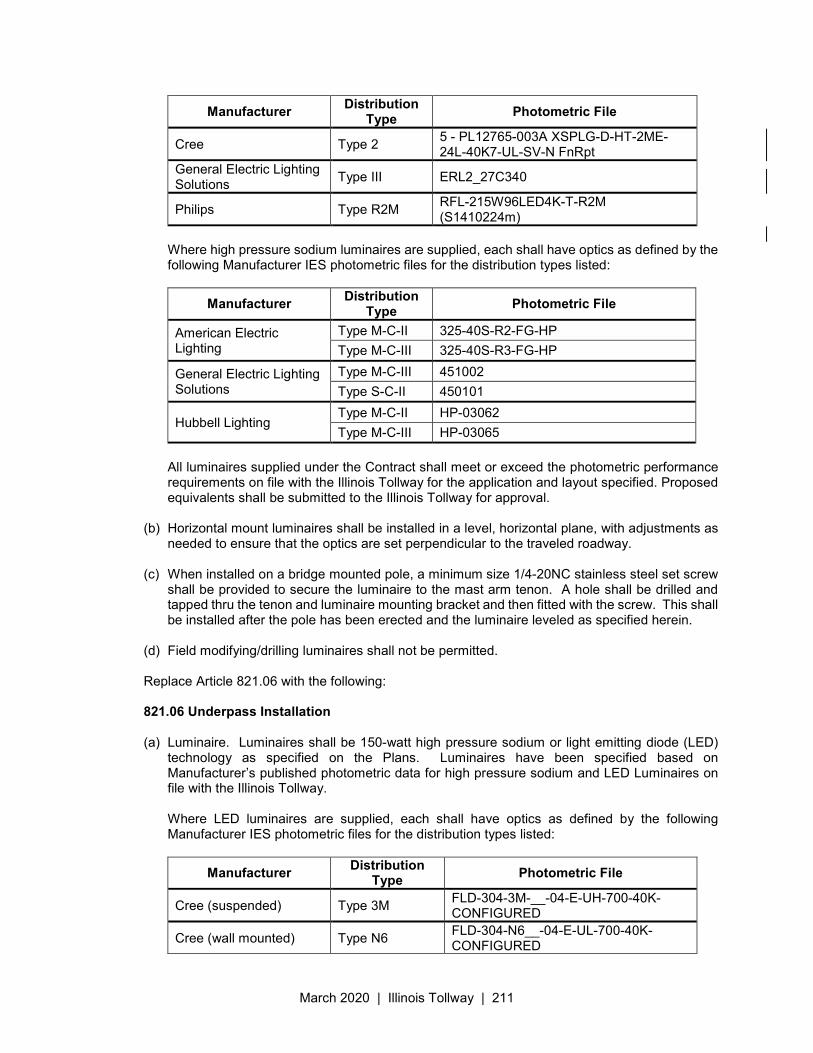
March 2020 | Illinois Tollway | 211
Manufacturer Distribution
Type Photometric File
Cree Type 2 5 - PL12765-003A XSPLG-D-HT-2ME-24L-40K7-UL-SV-N FnRpt
General Electric Lighting Solutions
Type III ERL2_27C340
Philips Type R2M RFL-215W96LED4K-T-R2M (S1410224m)
Where high pressure sodium luminaires are supplied, each shall have optics as defined by the following Manufacturer IES photometric files for the distribution types listed:
Manufacturer Distribution
Type Photometric File
American Electric Lighting
Type M-C-II 325-40S-R2-FG-HP
Type M-C-III 325-40S-R3-FG-HP
General Electric Lighting Solutions
Type M-C-III 451002
Type S-C-II 450101
Hubbell Lighting Type M-C-II HP-03062
Type M-C-III HP-03065
All luminaires supplied under the Contract shall meet or exceed the photometric performance requirements on file with the Illinois Tollway for the application and layout specified. Proposed equivalents shall be submitted to the Illinois Tollway for approval.
(b) Horizontal mount luminaires shall be installed in a level, horizontal plane, with adjustments as needed to ensure that the optics are set perpendicular to the traveled roadway.
(c) When installed on a bridge mounted pole, a minimum size 1/4-20NC stainless steel set screw shall be provided to secure the luminaire to the mast arm tenon. A hole shall be drilled and tapped thru the tenon and luminaire mounting bracket and then fitted with the screw. This shall be installed after the pole has been erected and the luminaire leveled as specified herein.
(d) Field modifying/drilling luminaires shall not be permitted. Replace Article 821.06 with the following: 821.06 Underpass Installation
(a) Luminaire. Luminaires shall be 150-watt high pressure sodium or light emitting diode (LED)
technology as specified on the Plans. Luminaires have been specified based on Manufacturer’s published photometric data for high pressure sodium and LED Luminaires on file with the Illinois Tollway. Where LED luminaires are supplied, each shall have optics as defined by the following Manufacturer IES photometric files for the distribution types listed:
Manufacturer Distribution
Type Photometric File
Cree (suspended) Type 3M FLD-304-3M-__-04-E-UH-700-40K-CONFIGURED
Cree (wall mounted) Type N6 FLD-304-N6__-04-E-UL-700-40K-CONFIGURED
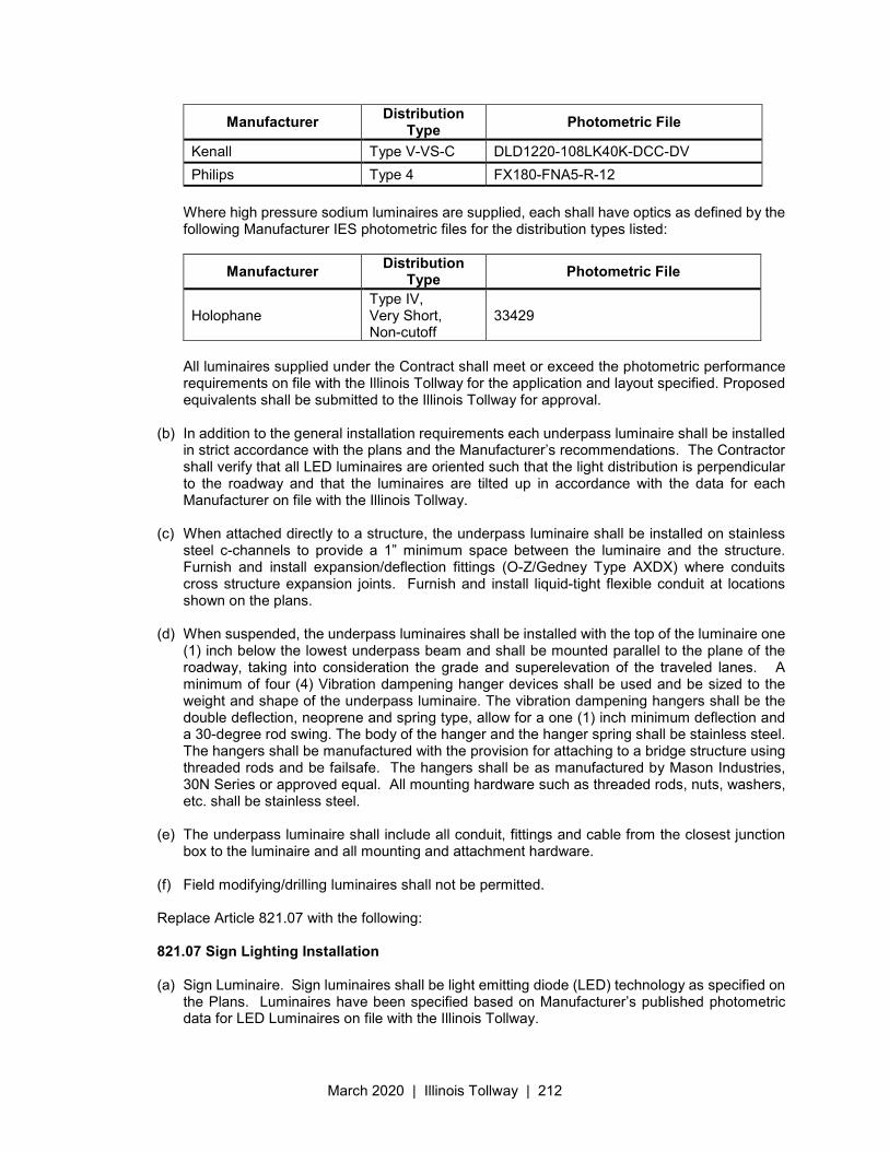
March 2020 | Illinois Tollway | 212
Manufacturer Distribution
Type Photometric File
Kenall Type V-VS-C DLD1220-108LK40K-DCC-DV
Philips Type 4 FX180-FNA5-R-12
Where high pressure sodium luminaires are supplied, each shall have optics as defined by the following Manufacturer IES photometric files for the distribution types listed:
Manufacturer Distribution
Type Photometric File
Holophane Type IV, Very Short, Non-cutoff
33429
All luminaires supplied under the Contract shall meet or exceed the photometric performance requirements on file with the Illinois Tollway for the application and layout specified. Proposed equivalents shall be submitted to the Illinois Tollway for approval.
(b) In addition to the general installation requirements each underpass luminaire shall be installed in strict accordance with the plans and the Manufacturer’s recommendations. The Contractor shall verify that all LED luminaires are oriented such that the light distribution is perpendicular to the roadway and that the luminaires are tilted up in accordance with the data for each Manufacturer on file with the Illinois Tollway.
(c) When attached directly to a structure, the underpass luminaire shall be installed on stainless steel c-channels to provide a 1” minimum space between the luminaire and the structure. Furnish and install expansion/deflection fittings (O-Z/Gedney Type AXDX) where conduits cross structure expansion joints. Furnish and install liquid-tight flexible conduit at locations shown on the plans.
(d) When suspended, the underpass luminaires shall be installed with the top of the luminaire one (1) inch below the lowest underpass beam and shall be mounted parallel to the plane of the roadway, taking into consideration the grade and superelevation of the traveled lanes. A minimum of four (4) Vibration dampening hanger devices shall be used and be sized to the weight and shape of the underpass luminaire. The vibration dampening hangers shall be the double deflection, neoprene and spring type, allow for a one (1) inch minimum deflection and a 30-degree rod swing. The body of the hanger and the hanger spring shall be stainless steel. The hangers shall be manufactured with the provision for attaching to a bridge structure using threaded rods and be failsafe. The hangers shall be as manufactured by Mason Industries, 30N Series or approved equal. All mounting hardware such as threaded rods, nuts, washers, etc. shall be stainless steel.
(e) The underpass luminaire shall include all conduit, fittings and cable from the closest junction box to the luminaire and all mounting and attachment hardware.
(f) Field modifying/drilling luminaires shall not be permitted. Replace Article 821.07 with the following: 821.07 Sign Lighting Installation (a) Sign Luminaire. Sign luminaires shall be light emitting diode (LED) technology as specified on
the Plans. Luminaires have been specified based on Manufacturer’s published photometric data for LED Luminaires on file with the Illinois Tollway.
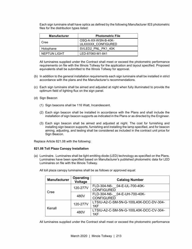
March 2020 | Illinois Tollway | 213
Each sign luminaire shall have optics as defined by the following Manufacturer IES photometric files for the distribution types listed:
Manufacturer Photometric File
Cree OSQ-A-XX-WSN-B-40K-ULXXXXX_CONFIGURED
Holophane SVLED2_PNL_PK1_40K
NEPTUN LIGHT LED-87060-M1-841
All luminaires supplied under the Contract shall meet or exceed the photometric performance requirements on file with the Illinois Tollway for the application and layout specified. Proposed equivalents shall be submitted to the Illinois Tollway for approval.
(b) In addition to the general installation requirements each sign luminaire shall be installed in strict accordance with the plans and the Manufacturer’s recommendations.
(c) Each sign luminaire shall be aimed and adjusted at night when fully illuminated to provide the optimum field of lighting flux on the sign panel.
(d) Sign Beacon
(1) Sign beacons shall be 116 Watt, Incandescent.
(2) Each sign beacon shall be installed in accordance with the Plans and shall include the installation of sign beacon supports as indicated in the Plans or as directed by the Engineer.
(3) Each sign beacon shall be aimed and adjusted at night. The cost for furnishing and installing sign beacon supports, furnishing and installing the lamp specified, and for beacon aiming, adjusting, and testing shall be considered as included in the contract unit price for Sign Beacon.
Replace Article 821.08 with the following: 821.08 Toll Plaza Canopy Installation
(a) Luminaire. Luminaires shall be light emitting diode (LED) technology as specified on the Plans.
Luminaires have been specified based on Manufacturer’s published photometric data for LED Luminaires on file with the Illinois Tollway. All toll plaza canopy luminaires shall be as follows or approved equal:
Manufacturer Operating Voltage
Catalog Number
Cree 120-277V
FLD-304-N6-__04-E-UL-700-40K- CONFIGURED
480V FLD-304-N6-__04-E-UH-700-40K- CONFIGURED
Kenall 120-277V
LTSIU-A2-C-SM-5N-G-100L40K-DCC-DV-304-1KF
480V LTSIU-A2-C-SM-5N-G-100L40K-DCC-CV-304-1KF
All luminaires supplied under the Contract shall meet or exceed the photometric performance
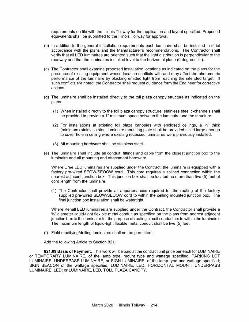
March 2020 | Illinois Tollway | 214
requirements on file with the Illinois Tollway for the application and layout specified. Proposed equivalents shall be submitted to the Illinois Tollway for approval.
(b) In addition to the general installation requirements each luminaire shall be installed in strict accordance with the plans and the Manufacturer’s recommendations. The Contractor shall verify that all LED luminaires are oriented such that the light distribution is perpendicular to the roadway and that the luminaires installed level to the horizontal plane (0 degrees tilt).
(c) The Contractor shall examine proposed installation locations as indicated on the plans for the presence of existing equipment whose location conflicts with and may affect the photometric performance of the luminaire by blocking emitted light from reaching the intended target. If such conflicts are noted, the Contractor shall request guidance form the Engineer for corrective actions.
(d) The luminaire shall be installed directly to the toll plaza canopy structure as indicated on the plans.
(1) When installed directly to the toll plaza canopy structure, stainless steel c-channels shall
be provided to provide a 1” minimum space between the luminaire and the structure.
(2) For installations at existing toll plaza canopies with enclosed ceilings, a ¼” thick (minimum) stainless steel luminaire mounting plate shall be provided sized large enough to cover hole in ceiling where existing recessed luminaires were previously installed.
(3) All mounting hardware shall be stainless steel.
(e) The luminaire shall include all conduit, fittings and cable from the closest junction box to the luminaire and all mounting and attachment hardware. Where Cree LED luminaires are supplied under the Contract, the luminaire is equipped with a factory pre-wired SEOW/SEOOW cord. This cord requires a spliced connection within the nearest adjacent junction box. This junction box shall be located no more than five (5) feet of cord length from the luminaire. (1) The Contractor shall provide all appurtenances required for the routing of the factory
supplied pre-wired SEOW/SEOOW cord to within the celling mounted junction box. The final junction box installation shall be watertight.
Where Kenall LED luminaires are supplied under the Contract, the Contractor shall provide a ¾” diameter liquid-tight flexible metal conduit as specified on the plans from nearest adjacent junction box to the luminaire for the purpose of routing circuit conductors to within the luminaire. The maximum length of liquid-tight flexible metal conduit shall be five (5) feet.
(f) Field modifying/drilling luminaires shall not be permitted. Add the following Article to Section 821:
821.09 Basis of Payment. This work will be paid at the contract unit price per each for LUMINAIRE
or TEMPORARY LUMINAIRE, of the lamp type, mount type and wattage specified; PARKING LOT LUMINAIRE, UNDERPASS LUMINAIRE, or SIGN LUMINAIRE, of the lamp type and wattage specified; SIGN BEACON of the wattage specified; LUMINAIRE, LED, HORIZONTAL MOUNT; UNDERPASS LUMINAIRE, LED; or LUMINAIRE, LED, TOLL PLAZA CANOPY.
March 2020 | Illinois Tollway | 215
Illinois State Toll Highway Authority
SUPPLEMENTAL SPECIFICATION FOR
SECTION 823. SIGN STRUCTURE WIRING
Issued April 1, 2016
This Supplemental Specification amends and supersedes the provisions of the Illinois Department of Transportation Standard Specifications for Road and Bridge Construction, adopted April 1, 2016 and shall be construed to be a part thereof, superseding any conflicting provisions thereof applicable to the work under the contract.
Add the following new articles: 823.01 Description. This item shall consist of furnishing all material and work required to energize
and put sign luminaires and sign beacons into satisfactory operation on overhead, cantilever, and bridge mounted sign structures, and sign beacons on ground mounted signs in accordance with the Plans and as shown in the plans. This shall include control panels complete with junction box, circuit breakers, flashing beacon controllers, and all conduit and wiring to the luminaire mounting locations on the sign structure, and elsewhere where required. The feeder, up to the sign structure as shown on the plans or as directed by the Engineer will be paid for separately.
823.02 Materials. Materials shall be according to the following Articles of Division 1000 – Materials
of the Standard Specifications and as modified or supplemented by the Illinois Tollway Supplemental Specifications.
Item Article/Section
(a) Electric Raceway Material ....................................................... 1088 (b) Conductors .............................................................................. 1066.02 (c) Insulation ................................................................................. 1066.03(a) (d) Junction Boxes ........................................................................ 1088.04 (e) Grounding Materials ................................................................ 1087 (f) Beacon Flashers. The beacon flasher shall consist of a solid-state flasher assembly installed
in a weather proof enclosure unless otherwise specified in the Special Provisions or shown in the plans. The beacon flasher shall consist of the following Pelco Products, Inc., or approved equal components: (1) Cabinet for top or bottom mounting, Part No. SE-1003.
(2) Flasher assembly shall be a solid state, 120-volt, 15-ampere, 2-circuit NEMA flasher. The
flasher assembly shall operate over an ambient temperature range from -37°C to +74°C, with an on-off power within 5 electrical degrees of the zero-voltage point. The flash rate shall be 56±3 times per minute. The flasher shall be Part No. SM-0179.
(3) Socket for NEMA flasher, Part No. SM-0196.
(4) Mounting bracket for the NEMA flasher, Part No. SM-0215.
(5) Terminal strip, Part No. SM-0164.
(6) Circuit breaker, Part No. SM-0216.
(7) Toggle switch, Part No. SM-0217.
March 2020 | Illinois Tollway | 216
(8) Mounting bracket for the circuit breaker and toggle switch, Part No. SM-0218.
(9) Pop rivet, Part No. FS-6402.
CONSTRUCTION REQUIREMENTS 823.03 General. All materials including conduit, wire, all necessary devices and miscellaneous
hardware required for the satisfactory operation of a sign lighting system shall be provided. All testing and collateral work necessary to place all luminaires and beacons in operation, and all labor, equipment, tools, and incidentals necessary to complete the work as specified shall also be included.
Where removal of existing sign lighting equipment is required before new sign lighting equipment
can be installed, the new sign lighting system shall be put in operation within three (3) days from the time the existing system is deenergized for removal.
823.04 Installation. Conduit installed on overhead, cantilever, and bridge mounted sign structures
and for flashers on ground mounted signs shall be heavy wall PVC coated rigid aluminum or PVC coated rigid galvanized steel conduit as shown on the Plans. Conduit fittings, boxes and enclosures shall be of PVC coated cast metal construction of the same material as the conduit attached. All elbows, tees and entrance fittings, boxes and housings shall be gasketed rain tight. Conduit and fittings shall be heavy wall PVC coated rigid aluminum on aluminum portions of structures and heavy wall PVC coated rigid galvanized steel on galvanized steel portions of structures.
All conduit, elbows, fittings, couplings, etc., shall be installed with special care. The external
surfaces of conduit, elbows, etc., shall not be scratched, scraped, gouged, or damaged in any manner. Conduit shall be fastened to overhead, cantilever and bridge mounted sign structures with stainless
steel strapping as shown on the Plans. Conduit runs on wood posts for ground mounted signs shall be galvanized steel and shall be supported by malleable iron clamps and clamp backs, or pipe clamp brackets as shown on the Plans.
Expansion fittings shall be installed in each conduit run at bridge expansion joints. Expansion
fittings shall be sized as required. A bonding jumper shall be provided at each expansion joint fitting. The ends of the conduit shall be provided with insulating bushings of a type approved by the
Engineer. Circuit breaker boxes, junction boxes and flashing beacon controllers shall be mounted on stainless
steel plate panels attached to the structure end supports, columns or piers as shown on the Plans. All conduits shall be rigidly attached to the sign supports, trusses and walkway supports, and conductors drawn through the conduit. One pair of single conductor insulated wires suitable for 600-volt circuits shall be run from the junction box to each luminaire. Connections in the junction box shall be made at 30-ampere, 600-volt terminal blocks. No splices will be allowed between the junction box and the fixture.
Upon completion of all work, including the installation of sign luminaires and beacons as provided
under Section 821, the wiring and equipment shall be tested in accordance with the requirements of Section 801 prior to acceptance of the work by the Engineer.
823.05 Method of Measurement. Sign structure wiring will be measured per each unit, complete
and in place for each overhead, cantilever, bridge mounted or ground mounted sign structure. No separate measurement or payment will be made for aiming and adjustment of luminaires, or
testing. The costs therefore will be considered as included in the contract unit prices for the various types of SIGN STRUCTURE WIRING.
823.06 Basis of Payment. This work will be paid for at the contract unit price per each for SIGN
March 2020 | Illinois Tollway | 217
STRUCTURE WIRING, OVERHEAD SIGN; SIGN STRUCTURE WIRING, CANTILEVER SIGN; SIGN STRUCTURE WIRING, BRIDGE MOUNTED SIGN; or SIGN STRUCTURE WIRING, GROUND MOUNTED SIGN.
March 2020 | Illinois Tollway | 218
Illinois State Toll Highway Authority
SUPPLEMENTAL SPECIFICATION FOR
SECTION 825. LIGHTING CONTROLLER
Issued April 1, 2016 Revised May 1, 2017
This Supplemental Specification amends and supersedes the provisions of the Illinois Department of Transportation Standard Specifications for Road and Bridge Construction, adopted April 1, 2016 and shall be construed to be a part thereof, superseding any conflicting provisions thereof applicable to the work under the contract.
Delete Section 825 in its entirety and replace with the following 825.01 Description. This work shall consist of furnishing and installing an electrical control cabinet
with control devices, distribution equipment, and wiring for control of roadway lighting in accordance with the Plans and installing them on prepared foundations at locations indicated in the plans or as directed by the Engineer.
825.02 Materials. Materials shall be according to the following Articles of Division 1000 – Materials
of the Standard Specifications and as modified or supplemented by the Illinois Tollway Supplemental Specifications.
Item Article/Section
(a) Lighting Controller ................................................................... 1068.01 (b) Transformers, General Purpose .............................................. 1068.02 (c) Lightning Protection ................................................................. 1065.02 (d) Grounding Materials ................................................................ 1087 (e) Rigid Metal Conduit ................................................................. 1088.01(a) (f) Expansion Fittings ................................................................... 1088.02(a)
CONSTRUCTION REQUIREMENTS
825.03 Installation.
(a) Exterior Installations
a. General. The lighting controller shall be located as shown on the plans. The Contractor shall confirm the location and orientation of the door side with the Engineer, prior to installing the foundation. Each controller shall be set on a prepared concrete foundation with anchor bolts as detailed on the Plans.
b. All conduit entrances into each controller shall be field drilled and attachment made with waterproof hubs. The removable metal bottom plate shall be sealed with a rodent and dust/moisture barrier.
c. Roadway lighting branch circuit conductors shall be brought into the controller panelboard and be terminated at their respective circuit breakers as indicated in the plans. The conductors shall be neatly arranged in the gutters for ease in tracing.
March 2020 | Illinois Tollway | 219
d. Electric service conductors from the electrical service pedestal (specified elsewhere) shall be brought into the disconnect switch as indicated in the plans or as directed by the Engineer.
(b) Interior Installations
a. General. The lighting controller shall be located as shown on the plans. The Contractor shall confirm the location and orientation of the lighting control and distribution equipment with the Engineer, prior to installation. All lighting control and distribution equipment shall be mounted to the interior side of a building structural wall on a high strength, high arc resistant equipment mounting panel. The equipment mounting panel and all equipment shall be offset a minimum of one (1) inch from the face of the structural wall by use of stainless steel C-Channel capable of supporting the weight of the equipment as detailed on the Plans. A ground rod and connecting wire shall be installed for each lighting controller in accordance with the Plans.
b. All wiring within the building between the lighting control and power distribution equipment shall be installed within conduit in accordance with the Plans. The conduit system shall be installed complete with all accessories, fittings, boxes and supports in an approved and workmanlike manner to provide proper raceways for electrical conductors.
i. All conduit runs are shown diagrammatically on the Plans for the purposes of outlining the general method of routing the conduits to avoid interferences.
ii. All exposed conduits shall be installed true, plumb, parallel with or at right angles to adjacent building members and shall present and orderly, neat and workmanlike appearance.
iii. Field bends shall be carefully made to prevent conduit damage or reduction of the internal diameter. All bends shall be made with equipment specifically intended for the purpose of bending conduit. The bending radius shall not be less than six (6) times the nominal diameter of the conduit with carefully matched bends on parallel runs to present a neat and workmanlike appearance. The number of crossovers shall be kept to a minimum.
iv. Conduits which are crushed or deformed in any way shall not be installed.
v. All field cut conduits shall be carefully reamed inside and out to remove burrs. All field cut conduit ends shall be square and shall be performed with equipment specifically intended for the purpose of cutting conduit. The use of tube cutters is strictly prohibited. Conduits not properly cut shall be replaced at no additional cost to the Illinois Tollway.
vi. All field cut conduit threads shall be tapered and coated with an approved electrically conductive, corrosion resistant compound. No running threads will be permitted.
vii. All conduit joints shall be properly tightened, watertight, and provide a low resistance ground path in the conduit system.
viii. All conduits shall be carefully cleaned before and after installation and all internal surfaces shall be free from imperfections likely to damage the conductor insulation. After installation of complete runs, all conduits shall be snaked with an approved tube cleaner equipped with a cylindrical mandrel of a diameter not less than 85% of the nominal inside diameter of the conduit. Any conduits through which the
March 2020 | Illinois Tollway | 220
mandrel shall not pass shall be removed and replaced at no additional cost to the Illinois Tollway. All conduits installed with a nominal inside diameter of one (1) inch or smaller may be cleaned by pulling clean rags through the conduit. After cleaning, the ends of the conduits shall be protected to prevent entrance of water or any other foreign matter. The use of such items as plastic bags, tape, paper, rags, etc. as a means of protecting the conduits ends is strictly prohibited under any circumstances. Failure to properly protect the conduit ends after cleaning shall result in the Contractor having to again mandrel the conduit immediately before the installation of conductors at no additional cost to the Illinois Tollway.
ix. Lines of nylon, polyolefin or polypropylene propelled by carbon dioxide, vacuum or compressed air shall be used to snake or pull conductors into conduits. Flat steel tape may only be used for conduit runs less than fifty (50) feet in length. Metal cables are strictly prohibited for the purpose of pulling conductors into conduits. Non-metallic pulling taps may be used for all conduit installations.
x. Where conduits are connected to equipment enclosures or junction/pull boxes, field drilled holes or full size knockout openings shall provide electrical continuity for grounding and shall be assured by the use of bonding type locknuts. Where connections are at slightly eccentric openings, jumper type grounding bushings and wire jumpers shall be installed. Should the openings become excessively eccentric, as determined by the Engineer, the equipment enclosure or junction/pull box shall be replaced at no additional cost to the Illinois Tollway. The use of reducers for conduit connection to equipment enclosures or junction/pull boxes is strictly prohibited under any circumstances.
xi. Conduit systems shall be installed with fittings, couplings, connectors, double locknuts, bushings, etc. and made up tight to provide proper ground continuity throughout the system.
xii. As far as practical, conduits shall be pitched slightly to avoid trapping of condensate. Where necessary to secure drainage, a breather-drain fitting shall be installed in equipment enclosures or junction/pull boxes at low points. Each breather-drain fitting shall be as manufactured by Appleton Electric Company, Crouse-Hinds Company, or O.Z. Gedney. Care shall be taken to avoid drainage of one enclosure onto another.
xiii. The Contractor shall provide expansion/deflection fittings for metallic conduit systems where conduits cross building expansion joints or where conduits transfer between structurally independent supports. All fittings shall be provided with flexible grounding bonds bypassing the fittings to provide proper ground continuity throughout the system.
xiv. The number of conduit bends between pull points shall be limited to 270 degrees including all offsets, sweeps, kicks, etc.
xv. Conduits entering distribution panel enclosures shall be fitted with jumper type insulated grounding bushings, bonded together and to the structure of the enclosure by a continuous bonding conductor.
xvi. Conduits entering the building from outdoors are subject to moisture accumulation due to condensation or infiltration caused by non-watertight joints. All conduits entering the building from outdoors shall extend vertically one (1) foot above finished floor to reduce the possibility of water infiltration. After conductors are installed, the ends of these conduits shall be packed with non-setting sealing compound.
March 2020 | Illinois Tollway | 221
c. Roadway lighting branch circuit conductors shall be brought into the controller panelboard and be terminated at their respective circuit breakers as indicated in the plans. The conductors shall be neatly arranged in the gutters for ease in tracing.
d. Electric utility service conductors shall be brought into the meter socket or disconnect switch as indicated in the plans or as directed by the Engineer.
825.04 Grounding. A ground rod and connecting wire shall be installed for each controller in accordance with the Plans and as specified in Illinois Tollway Supplemental Specifications Section 806.
825.05 Basis of Payment. This work will be paid at the contract unit price per each for LIGHTING CONTROLLER, of the amperes and installation type specified.
March 2020 | Illinois Tollway | 222
Illinois State Toll Highway Authority
SUPPLEMENTAL SPECIFICATION FOR
SECTION 828. LIGHTING CONTROLLER FOUNDATION
Issued April 1, 2016
This Supplemental Specification amends and supersedes the provisions of the Illinois Department
of Transportation Standard Specifications for Road and Bridge Construction, adopted April 1, 2016 and shall be construed to be a part thereof, superseding any conflicting provisions thereof applicable to the work under the contract.
Add the following new articles: 828.01 Description. This item shall consist of constructing reinforced concrete foundations for
lighting controllers. Each such foundation shall be of the type indicated in the plans and shall be constructed in accordance with the Plans.
828.02 Materials. Materials shall be according to the following Articles of Division 1000 – Materials
of the Standard Specifications and as modified or supplemented by the Illinois Tollway Supplemental Specifications.
Item Article/Section
(a) Portland Cement Concrete (Class SI) ..................................... 1020 (b) Reinforcement Bars ................................................................. 1006.10 (c) Conduit .................................................................................... 1088.01 (d) Anchor Rods ............................................................................ 1006.09 (e) Structural Steel ........................................................................ 1006.04
CONSTRUCTION REQUIREMENTS 828.03 Installation
(a) General. Each foundation for a lighting controller shall be constructed in accordance with the Plans for the type specified in the plans.
Stainless steel rigid conduits shall be provided in each foundation for service cable and roadway lighting conductors and cable ducts in accordance with the Plan details. A minimum of two (2) spare 3-inch conduits shall be provided at each controller. One (1) Schedule 40 PVC conduit shall be provided in each foundation for ground wire in accordance with the Plans.
All applicable provisions of Section 503 shall govern.
Excavation and backfill required will not be measured separately for payment, but will be considered as included in the contract unit price for Lighting Controller Foundation, Type A or Type B.
Anchor bolts and all required conduits and cable duct sleeves shall be firmly secured in place in the forms prior to placement of concrete. Conduits and cable duct sleeves shall be capped to prevent the entry of concrete or other foreign material during placement and finishing operations.
March 2020 | Illinois Tollway | 223
(b) Type B Lighting Controller Foundation. The structural steel handrail shall be hot-dip galvanized after fabrication. The handrail shall be attached to the working platform with galvanized studs anchored in drilled holes with epoxy grout; or with galvanized bolts in threaded steel sockets which are anchored in drilled holes with epoxy grout. The epoxy grout shall be a pre-packaged self-contained system including the two epoxy components and the filler which are pre-measured and contained in a glass vial to be shattered by impact to mix the components. In use of such a system, the drilled hole for the glass vial shall be specifically sized by the Manufacturer for the size of anchor bolt or dowel to be installed.
828.04 Basis of Payment. This work will be paid at the contract unit price per each for LIGHTING CONTROLLER FOUNDATION of the type specified.
March 2020 | Illinois Tollway | 224
Illinois State Toll Highway Authority
SUPPLEMENTAL SPECIFICATION FOR
SECTION 830. LIGHT POLES
Issued April 1, 2016 Revised March 23, 2020
This Supplemental Specification amends and supersedes the provisions of the Illinois Department of Transportation Standard Specifications for Road and Bridge Construction, adopted April 1, 2016 and shall be construed to be a part thereof, superseding any conflicting provisions thereof applicable to the work under the contract.
Replace Article 830.01 with the following; 830.01 Description. This work shall consist of furnishing and installing a light pole complete with a
truss type mast arm(s) and mast arm cable assembly(ies), and all hardware and accessories required for the intended temporary or permanent use of the pole.
Section 830 of the Standard Specifications for Road and Bridge Construction, adopted April 1, 2016
shall be modified as follows: Replace Article 830.02 with the following: 830.02 Materials. Materials shall be according to the following Articles of Division 1000 – Materials
of the Standard Specifications and as modified or supplemented by the Illinois Tollway Supplemental Specifications.
Item Article/Section
(a) Light Poles ............................................................................... 1069 (b) Breakaway Devices ................................................................. 1070.04 Replace the first paragraph of Article 830.03 with the following paragraphs: 830.03 Installation. The light poles shall be erected and placed on their foundations in accordance
with Manufacturer’s recommendations. Care shall be exercised in handling and erecting the poles so as not to damage the finish. Rope or canvas slings shall be used in moving light poles. Each light pole shall be erected plumb with arm and luminaire in place.
Add the following paragraphs to Article 830.03; The truss type mast arm and luminaire cable assembly shall be installed as indicated in the plan
details. The aluminum pole cap and luminaire lid may be removed to allow for the routing of the cable. The cable shall be routed around the bolts for the luminaire connection bracket encompassing a minimum of two (2) bolts. Each end of the cable shall be connected with a minimum of two (2) stainless steel wire rope clips as indicated. Reattach pole cap with three (3) new ¼” stainless steel hex head screws and close the luminaire lid. Slack shall be provided in the luminaire cable assembly as shown in the plans. Excess slack shall be tucked into the end of the mast arm to avoid entanglement with luminaire fixture.
Prior to the installation of any cable assemblies, the Contractor shall demonstrate to the
satisfaction of the Engineer their methods of routing the cable within the luminaire, clipping the loops at each end, and (for single arm poles) attaching to the steel plate. The Engineer shall provide photos of the cable routing for upload to the Illinois Tollway Web Based Program Management (WBPM) system.
March 2020 | Illinois Tollway | 225
Each pole shall be tagged with an aluminum tag showing a unique identifier (Pole Inventory
Number Convention as described below) and the year of installation. The tag shall always be placed on the side of the light pole facing roadway traffic, or towards lower milepost for median mounted poles. The tag shall be attached to the pole with adhesive at a distance of 6 feet above the roadway elevation and shall be a minimum 4” wide by 2“ high, yellow color. Character height shall be 1”. The tag and adhesive shall be for exterior use and provide a minimum of 15 years of service.
In addition, each truss type mast arm shall be tagged with a unique identifier (Pole Inventory
Number Convention as described below). Same type and requirements for the pole tags shall apply to the truss type mast arm tag, except character font shall be 1/2 inch. The tag shall be attached to the bottom of the lower truss arm and oriented to be read when facing the direction of traffic.
The Pole Inventory Number Convention shall be as follows:
Tollway, Milepost, Type, Direction, Ramp location TOLLWAY: EW = Reagan Memorial Tollway (I-88)
NS = Veterans Memorial Tollway (I-355)
NW = Jane Addams Memorial Tollway (I-90)
TS = Tri-State Tollway (I-294 & I-294/I-80)
TN = Tri-State Tollway (I-94)
ES = Eden’s Spur (I-94)
EO = Elgin-O’Hare Tollway (IL-390)
WA = West O’Hare Access Bypass (I-490)
MILEPOST: Milepost to the hundredth (i.e. 14.75)
TYPE: The type only refers to the basic shape of the light pole
P = Single Mast Arm
T = Twin Mast Arms, add direction (E, W, N, or S) to identify which
arm
DIRECTION: EB, SB, WB, NB Inventory direction of the roadway, or X for centerline
median
RAMP: (R#) = along ramp (omitted if not along ramp), where R is the letter
designation of the ramp and # is the sequential numbering of the pole in
the direction of travel along the ramp
EXAMPLES: 1) TS38.40TE NB for a northbound-side arm of a twin mast light pole with located along the Tri-State Tollway (I-294) at milepost 38.40
2) NW8.54P EB(R10) for a single mast light pole and arm on eastbound I-90, being the tenth pole along a ramp at mile post 8.54.
Add the following paragraphs to Article 830.03:
(d) Ground Mounted Light Poles. All ground mounted light poles shall be provided with an approved FHWA breakaway device as specified in Illinois Tollway Supplemental Specification Sections 838 and 1070. Breakaway devices shall not be measured for payment but shall be included in the cost of the Light Pole.
The use of galvanized steel U-shaped shims under the pole base will be permitted for plumbing ground mounted light poles only. Shims shall be provided in increments of nominal thickness not exceeding 1/8 inch. Shimming of more than 1/8 inch is permitted at any individual anchor bolt if a 3/4-inch steel leveling plate ASTM A-36 (AASHTO M183) is used, providing that sufficient thread is exposed to fully contact the hex nuts and that grading be level with the top of the leveling pad. When more than 3/4 inch of shimming is required, the necessary
March 2020 | Illinois Tollway | 226
corrections shall be made to the foundation surface. Bending of anchor bolts will not be permitted.
(e) Structural Parapet Wall Mounted Light Poles. Structural parapet wall mounted light poles shall have standard pole bases. Breakaway poles or devices shall not be used on any structural parapet wall mounted light poles. Installation shall include a vibration isolation pad, vibration isolation washers and leveling plate as shown on the Plans and as follows:
(1) Vibration isolation pads and washers, including all incidental hardware, shall be as manufactured by Fabreeka or Voss Engineering Co.
a. The vibration isolation pad shall be pre-formed with matching outline dimensions to conform with the light pole base plate.
b. The vibration isolation pad shall be made with new unvulcanized rubber and unused fabric fibers in proper proportion to maintain strength and stability.
c. The vibration isolation pad surface hardness shall be 80±, as measured on a Shore A Durometer.
d. The ultimate breakdown of the vibration isolation pad under compressive loading shall be no less than 10,000 lbs/square inch for the specified thickness without extrusion or detrimental reduction in thickness.
e. A set of 4 vibration isolation washers shall be provided, 1/2 inch thick and constructed of the same material as provided for the vibration pads.
(2) A set of 4 leveling nuts shall be provided for each pole.
(3) A 3/4" steel leveling plate ASTM A-36 (AASHTO M183) shall be furnished to rest atop the leveling nuts. The leveling plate shall have matching outline dimensions to conform with the light pole base plate.
(f) Barrier Wall Mounted Light Poles. Barrier Wall mounted poles shall have standard pole bases. Breakaway poles or devices shall not be used on barrier walls or retaining walls. Installation shall include a leveling plate as shown on the Plans and as follows:
(1) A set of 4 leveling nuts shall be provided for each pole.
(2) A 3/4" steel leveling plate ASTM A-36 (AASHTO M183) shall be furnished to rest atop the leveling nuts. The leveling plate shall have matching outline dimensions to conform with the light pole base plate.
In Article 830.05 delete the last paragraph (“When breakaway devices are specified, the devices will be paid for separately according to Articles 838.04 and 838.05.”).
March 2020 | Illinois Tollway | 227
Illinois State Toll Highway Authority
SUPPLEMENTAL SPECIFICATION FOR
SECTION 836. POLE FOUNDATION
Issued April 1, 2016
This Supplemental Specification amends and supersedes the provisions of the Illinois Department of Transportation Standard Specifications for Road and Bridge Construction, adopted April 1, 2016 and shall be construed to be a part thereof, superseding any conflicting provisions thereof applicable to the work under the contract.
Section 836 of the Standard Specifications for Road and Bridge Construction, adopted April 1, 2016
shall be modified as follows. Replace Article 836.02 with the following: 836.02 Materials. Materials shall be according to the following Articles of Division 1000 – Materials
of the Standard Specifications and as modified or supplemented by the Illinois Tollway Supplemental Specifications.
Item Article/Section
(a) Portland Cement Concrete ...................................................... 1020 (b) Anchor Rods ............................................................................ 1070.02 (c) Light Pole Foundation, Metal ................................................... 1070.01 (d) Fine Aggregate ........................................................................ 1003.04 (e) Grout (Note 1) .......................................................................... 1024.01
Note 1. The grout mixture shall be one part cement and two parts sand mixed with water.
Add the following paragraphs to Article 836.02:
(f) Curing compound shall comply with ASTM Class B. Type 1 compound shall be shall be ASTM (AASTHO) Type 1.C 309 and ASTM C 156 for liquid membrane forming curing compound, and shall be a linseed oil emulsion. The Contractor shall furnish a certification to the Engineer attesting that the compound to be used meets the requirements of the cited ASTM Standards and is in fact a linseed oil emulsion. The engineer reserves the right to have the material certification verified in a laboratory.
(g) Preformed joint filler shall comply with ASTM D 1752, Type III self-expanding cork joint filler.
Replace the first paragraph of Article 836.03(a) with the following paragraphs:
(a) Drilled Shaft Foundations. Drilled shaft foundations shall be to the depth shown on the Plans unless shown otherwise on the contract plans or directed by the Engineer. Each foundation shall be constructed in accordance with the details shown in the Plans unless directed otherwise by the Engineer.
Parking lot foundations shall be constructed in accordance with the details shown in the Plans. When details for parking lot foundations are not included in the Contract Plans they shall be constructed in accordance with the Plans for concrete Light Standard Foundations, located as directed by the Engineer.
March 2020 | Illinois Tollway | 228
Drilled shaft foundations shall be constructed according to Section 516 of the Standard Specifications and the following.
Replace Article 836.03(b) with the following:
(b) Metal Foundations. Steel helix foundations shall be fabricated as shown on the Plans. Steel helix foundations shall be used only for roadway lighting and ITS applications and shall be installed in a manner acceptable to the Engineer and to the depths indicated in the Plans.
The steel helix foundation shall be installed in accordance with the Manufacturer’s recommended procedures. The installation shall be accomplished by either a boom type or a bed mounted type digger truck. The maximum torque limit of 13,000 ft.-lb. should not be exceeded since the possible damage to the foundation could occur. In the case of extremely difficult soils that cause the mechanical limit of the foundation to be exceeded, the foundation may be installed at the discretion of the Engineer in one of two methods. Predrilling a hole that is less than the shaft diameter of the foundation or using water as a lubricant. When foundation is installed by either method, minimum torque requirements of 5000 ft.-lb. are to be followed. The installation torque may be measured by torque measuring devices currently available or by calibrating the hydraulic system of the installing equipment.
Any voids within the metal screw-in foundation shall be filled with fine aggregate. A ground rod and connecting wire shall be installed in conjunction with each foundation as shown on the Plans.
Add the following paragraphs to Article 836.03:
(c) Median Barrier Wall Foundations. The top portion of the foundation shall be integrated with a portion of the median barrier wall, as one monolithic structure, as shown on the Plans and as directed by the Engineer. This portion of the foundation shall be of the same shape as the wall and shall be constructed according to the applicable portions of Articles 503.06 and 503.07 of the Standard Specifications. Any required sheeting, cribbing or other associated work required to complete the foundation work shall be included. The length of the wall included shall be as shown on the Plans or contract plans.
The drilled shaft portion of the foundation shall be constructed in accordance of the requirements of Article 836.03(a). A ground rod and connecting wire shall be installed in conjunction with each foundation as shown on the Plans. If detailed in the plans expansion couplings shall be used at the expansion joints at either end of the foundation. If no specific details are included in the contract plans, a PVC coupling shall be installed at each preformed expansion joint as shown on the Plans.
(1) Finishing. The surface of the concrete barrier shall be finished according to Article 503.15 of the Standard Specifications, except all holes and honeycombs shall be patched immediately.
(2) Curing. The Concrete barrier shall be cured by application of a linseed emulsion applied under pressure, by means of an atomizing type spray nozzle, in such a manner as to cover the entire exposed surface uniformly at a rate of not less than one gallon per 175 square feet. Sufficient pressure shall be applied by the spray machine to force the compound to leave the nozzle as a fine mist. Application shall be by means of an airless spray gun or other type of spraying equipment approved by the Engineer. Orchard-type hand spray equipment is not acceptable.
March 2020 | Illinois Tollway | 229
The estimated wind velocity, at the time of application shall be noted and the rate of application adjusted to assure the specified yield of one gallon of emulsion in place for each 175 square feet. The linseed oil emulsion shall be applied to fresh concrete immediately after finishing and after any superficial free water has subsided. All surfaces shall be protected from damage for 72 hours after the application of the linseed oil emulsion.
Replace Article 836.04 with the following: 836.04 Method of Measurement. Pole foundations will be measured per each complete and in
place. Relocation of a foundation due to an obstruction and any shaft excavation to that point will not be
measured for payment. Excavation in rock will be measured for payment according to Article 502.12 of the Standard
Specifications. Replace Article 836.05 with the following:
836.05 Basis of Payment. This work will be paid at the contract unit price per each for LIGHT
POLE FOUNDATION (ROADWAY) STEEL HELIX (7 FT) OR CONCRETE; LIGHT POLE FOUNDATION (ROADWAY) STEEL HELIX (10 FT); LIGHT POLE FOUNDATION (ROADWAY) CONCRETE; LIGHT POLE FOUNDATION (PARKING LOT) CONCRETE; or LIGHT POLE FOUNDATION (ROADWAY) MEDIAN, of the type specified.
Excavation in rock will be paid for according to Article 502.13 of the Standard Specifications.
March 2020 | Illinois Tollway | 230
Illinois State Toll Highway Authority
SUPPLEMENTAL SPECIFICATION FOR
SECTION 838. BREAKAWAY DEVICES
Issued April 1, 2016
This Supplemental Specification amends and supersedes the provisions of the Illinois Department of Transportation Standard Specifications for Road and Bridge Construction, adopted April 1, 2016 and shall be construed to be a part thereof, superseding any conflicting provisions thereof applicable to the work under the contract.
Section 838 of the Standard Specifications for Road and Bridge Construction, adopted April 1, 2016
shall be modified as follows. Replace Article 838.02 with the following: 838.02 Materials. Materials shall be according to the following Articles of Division 1000 – Materials
of the Standard Specifications and as modified or supplemented by the Illinois Tollway Supplemental Specifications.
Item Article/Section
(a) Breakaway Devices ................................................................. 1070.04 Replace Article 838.03 with the following: 838.03 Installation. All entry points created by the use of breakaway devices shall be permanently
and completely sealed against rodent entry. This includes the pole base plate and foundation plate openings, elongated holes for anchor rods, the opening below the pole base plate, and the wiring windows of both concrete and steel foundations.
Breakaway devices are not allowed on bridge parapets, barrier walls, or pedestrian conflict areas. The Contractor shall verify the loading of the pole, mast arm(s), luminaire(s), and appurtenances
do not exceed the capacity of the breakaway device. All breakaway devices shall be transformer base type and shall be installed level and flush with the
foundation without the use of leveling washers or shims in accordance with the Manufacturer’s recommended installation procedures. The anchor bolts shall be inserted full depth into the slotted holes of the transformer base. The transformer base shall be installed with the access door aligned with the light pole handhole. All nuts, bolts, washers, and lock washers required for a complete installation of the transformer base shall be provided.
Replace Article 838.04 with the following: 838.04 Method of Measurement. Breakaway devices shall not be measured for payment when
specified as part of Ground Mounted Light Poles as specified in these Supplemental Specifications Section 830 but shall be included in the cost of the Light Pole.
Breakaway devices specified for installation to existing light poles or separately from new light poles
will be measured for payment as each, for each transformer base installed complete. Replace Article 838.05 with the following:
March 2020 | Illinois Tollway | 231
838.04 Basis of Payment. Where measured for payment as specified above, this work will be paid for at the contract unit price per each for BREAKAWAY DEVICE, TRANSFORMER BASE, of the bolt circle indicated.
March 2020 | Illinois Tollway | 232
Illinois State Toll Highway Authority
SUPPLEMENTAL SPECIFICATION FOR
SECTION 841. TEMPORARY LIGHTING REMOVAL
Issued April 1, 2016
This Supplemental Specification amends and supersedes the provisions of the Illinois Department of Transportation Standard Specifications for Road and Bridge Construction, adopted April 1, 2016 and shall be construed to be a part thereof, superseding any conflicting provisions thereof applicable to the work under the contract.
Section 841 of the Standard Specifications for Road and Bridge Construction, adopted April 1, 2016
shall be modified as follows. Replace Article 841.03 with the following: 841.03 Method of Measurement and Basis of Payment. No separate measurement or payment
will be made for temporary lighting removal. The cost for this work in accordance with these Specifications shall be considered as included in the cost for MAINTAIN LIGHTING SYSTEM.
Delete Article 841.04.
March 2020 | Illinois Tollway | 233
Illinois State Toll Highway Authority
SUPPLEMENTAL SPECIFICATION FOR
SECTION 842. REMOVAL OF LIGHTING UNITS
Issued April 1, 2016
This Supplemental Specification amends and supersedes the provisions of the Illinois Department of Transportation Standard Specifications for Road and Bridge Construction, adopted April 1, 2016 and shall be construed to be a part thereof, superseding any conflicting provisions thereof applicable to the work under the contract.
Section 842 of the Standard Specifications for Road and Bridge Construction, adopted April 1, 2016
shall be modified as follows. Revise Article 842.03(b) to read:
(b) Removal of Lighting Unit, Salvage. Aluminum poles, mast arms, luminaires and all associated hardware and appurtenances shall remain the property of the Illinois Tollway and shall be delivered to an Illinois Tollway facility, as designated by the Engineer. All materials shall be unloaded and stacked there as directed by the Engineer.
Luminaires shall be removed and be boxed in new containers, approved by the Engineer. Wood blocking, banding and other appurtenant items required for the proper stacking and protection shall be included.
Add the following paragraphs to Article 842.03:
(c) When any light pole is found to have a sign or signs attached, the Contractor shall notify the Illinois Tollway’s Sign Shop not less than five (5) working days prior to the removal of such pole. This five (5) day advance notice notwithstanding, the removal of any such pole shall not be undertaken until the sign or signs have been removed. The Contractor is not authorized to remove such signs unless specifically so directed by the Engineer.
(d) Removal of Underpass and Sign Luminaires. Underpass and sign luminaires which are removed shall become the property of the Contractor and shall be disposed of according to Article 202.03 of the Standard Specifications.
Revise the last sentence of the third paragraph of Article 842.04 to read:
Those foundations deemed reusable by the Engineer shall be thoroughly cleaned (inside and outside) and be delivered to an Illinois Tollway facility, as designated by the Engineer. All materials shall be unloaded and stacked there as directed by the Engineer. Wood blocking, banding and other appurtenant items required for the proper stacking and protection shall be included.
Replace Article 842.06 with the following: 842.06 Basis of Payment. Removal of lighting units will be paid for at the contract unit price per
each for REMOVAL OF EXISTING LIGHTING UNIT, SALVAGE; REMOVAL OF EXISTING LIGHTING UNIT, NO SALVAGE; REMOVAL OF SIGN LUMINAIRE; or REMOVAL OF UNDERPASS LUMINAIRE.
Foundation removal will be paid for at the contract unit price per each for POLE FOUNDATION,
REMOVED or POLE FOUNDATION REMOVED, METAL.
March 2020 | Illinois Tollway | 234
Illinois State Toll Highway Authority
SUPPLEMENTAL SPECIFICATION FOR
SECTION 845. REMOVAL OF LIGHTING CONTROLLER
Issued April 1, 2016
This Supplemental Specification amends and supersedes the provisions of the Illinois Department of Transportation Standard Specifications for Road and Bridge Construction, adopted April 1, 2016 and shall be construed to be a part thereof, superseding any conflicting provisions thereof applicable to the work under the contract.
Section 845 of the Standard Specifications for Road and Bridge Construction, adopted April 1, 2016
shall be modified as follows. Revise Article 845.04 to read: 845.04 Removal of Lighting Controller. This work shall consist of the removal of the lighting
controller cabinet, enclosed electrical equipment, and all other miscellaneous items associated with the lighting controller.
Lighting controllers shall remain the property of the Illinois Tollway and shall be delivered to an
Illinois Tollway facility, as designated by the Engineer. Lighting Controllers shall be unloaded and stacked as directed by the Engineer. Wood blocking, banding and other appurtenant items required for the proper stacking and protection shall be included.
Any lighting controller or component that is lost or sustains sufficient damage to make it unfit for reuse,
shall be replaced by the Contractor at no additional cost to the Illinois Tollway.
March 2020 | Illinois Tollway | 235
Illinois State Toll Highway Authority
SUPPLEMENTAL SPECIFICATION FOR
SECTION 846. MAINTAIN LIGHTING SYSTEM
Issued April 1, 2016 Revised March 23, 2020
This Supplemental Specification amends and supersedes the provisions of the Illinois Department of Transportation Standard Specifications for Road and Bridge Construction, adopted April 1, 2016 and shall be construed to be a part thereof, superseding any conflicting provisions thereof applicable to the work under the contract.
Add the following new articles: 846.01 Description. This work shall consist of furnishing all labor, equipment, and incidental
materials for maintaining roadway lighting systems, parking lot lighting system, and sign lighting systems until the proposed new systems are installed, energized, tested, and accepted for operation by the Illinois Tollway. This work shall include both the existing system and any temporary system.
Temporary lighting controllers, light poles, mast arms, luminaires, conductors, and conduit sleeves
shall be paid as separate pay items when part of initial installation of temporary lighting systems. This work shall include all other necessary temporary devices required to maintain existing roadway illumination. All temporary lighting materials shall be furnished, installed, terminated, and maintained in service until the proposed lighting systems are installed, tested, and accepted for operation by the Illinois Tollway. All repair work required under maintenance terms shall reinstate the temporary lighting back to full compliance with the design of the system including all parts and components. The location and protection of all temporary devices necessary to comply with these requirements shall be subject to the approval of the Engineer.
Where removal of existing sign lighting equipment is required before new sign lighting equipment
can be installed, the new sign lighting system shall be put in operation within three (3) calendar days from the time the existing system is de-energized for removal.
Where existing signs that require lighting are being replaced with new sign panels that do not
require sign lighting, the existing sign lighting must remain in service until the new sign panels are installed. When the new sign panels are installed, the existing sign lighting system, including all conduit, wire, ballasts, circuit breakers, wireways, and luminaire support brackets shall be removed. Supply cables shall be disconnected and removed to their source,
All materials shall be furnished and delivered by the Contractor to the jobsite at no additional cost
to the Illinois Tollway. Effective the date the Contractor's activities (electrical or otherwise) at the job site begin, the
Contractor shall be responsible for the proper operation and maintenance of all existing and proposed lighting systems which are part of, or which may be affected by the work until final acceptance or as otherwise determined by the Engineer.
Before performing any excavation, removal, or installation work (electrical or otherwise) at the site,
the Contractor shall initiate a request for a maintenance transfer and preconstruction inspection, as specified elsewhere herein, to be held in the presence of the Engineer and a representative of the party or parties responsible for maintenance of any lighting systems which may be affected by the work. The request for the maintenance preconstruction inspection shall be made no less than seven (7) calendar days prior to the desired inspection date.
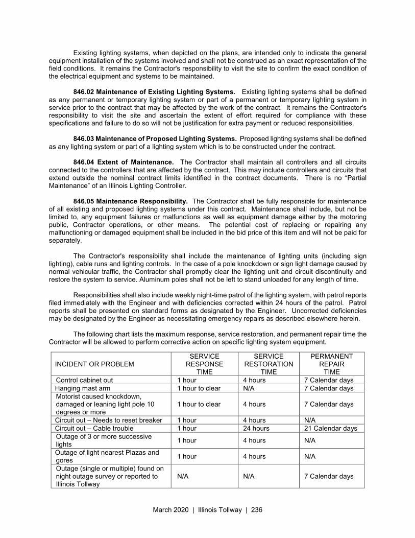
March 2020 | Illinois Tollway | 236
Existing lighting systems, when depicted on the plans, are intended only to indicate the general equipment installation of the systems involved and shall not be construed as an exact representation of the field conditions. It remains the Contractor's responsibility to visit the site to confirm the exact condition of the electrical equipment and systems to be maintained.
846.02 Maintenance of Existing Lighting Systems. Existing lighting systems shall be defined
as any permanent or temporary lighting system or part of a permanent or temporary lighting system in service prior to the contract that may be affected by the work of the contract. It remains the Contractor's responsibility to visit the site and ascertain the extent of effort required for compliance with these specifications and failure to do so will not be justification for extra payment or reduced responsibilities.
846.03 Maintenance of Proposed Lighting Systems. Proposed lighting systems shall be defined
as any lighting system or part of a lighting system which is to be constructed under the contract. 846.04 Extent of Maintenance. The Contractor shall maintain all controllers and all circuits
connected to the controllers that are affected by the contract. This may include controllers and circuits that extend outside the nominal contract limits identified in the contract documents. There is no “Partial Maintenance” of an Illinois Lighting Controller.
846.05 Maintenance Responsibility. The Contractor shall be fully responsible for maintenance
of all existing and proposed lighting systems under this contract. Maintenance shall include, but not be limited to, any equipment failures or malfunctions as well as equipment damage either by the motoring public, Contractor operations, or other means. The potential cost of replacing or repairing any malfunctioning or damaged equipment shall be included in the bid price of this item and will not be paid for separately.
The Contractor's responsibility shall include the maintenance of lighting units (including sign
lighting), cable runs and lighting controls. In the case of a pole knockdown or sign light damage caused by normal vehicular traffic, the Contractor shall promptly clear the lighting unit and circuit discontinuity and restore the system to service. Aluminum poles shall not be left to stand unloaded for any length of time.
Responsibilities shall also include weekly night-time patrol of the lighting system, with patrol reports
filed immediately with the Engineer and with deficiencies corrected within 24 hours of the patrol. Patrol reports shall be presented on standard forms as designated by the Engineer. Uncorrected deficiencies may be designated by the Engineer as necessitating emergency repairs as described elsewhere herein.
The following chart lists the maximum response, service restoration, and permanent repair time the
Contractor will be allowed to perform corrective action on specific lighting system equipment.
INCIDENT OR PROBLEM SERVICE
RESPONSE TIME
SERVICE RESTORATION
TIME
PERMANENT REPAIR
TIME Control cabinet out 1 hour 4 hours 7 Calendar days Hanging mast arm 1 hour to clear N/A 7 Calendar days Motorist caused knockdown, damaged or leaning light pole 10 degrees or more
1 hour to clear 4 hours 7 Calendar days
Circuit out – Needs to reset breaker 1 hour 4 hours N/A Circuit out – Cable trouble 1 hour 24 hours 21 Calendar days Outage of 3 or more successive lights
1 hour 4 hours N/A
Outage of light nearest Plazas and gores
1 hour 4 hours N/A
Outage (single or multiple) found on night outage survey or reported to Illinois Tollway
N/A N/A 7 Calendar days
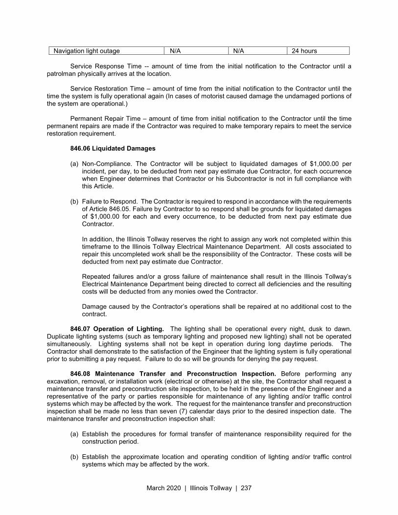
March 2020 | Illinois Tollway | 237
Navigation light outage N/A N/A 24 hours Service Response Time -- amount of time from the initial notification to the Contractor until a
patrolman physically arrives at the location. Service Restoration Time – amount of time from the initial notification to the Contractor until the
time the system is fully operational again (In cases of motorist caused damage the undamaged portions of the system are operational.)
Permanent Repair Time – amount of time from initial notification to the Contractor until the time
permanent repairs are made if the Contractor was required to make temporary repairs to meet the service restoration requirement.
846.06 Liquidated Damages
(a) Non-Compliance. The Contractor will be subject to liquidated damages of $1,000.00 per incident, per day, to be deducted from next pay estimate due Contractor, for each occurrence when Engineer determines that Contractor or his Subcontractor is not in full compliance with this Article.
(b) Failure to Respond. The Contractor is required to respond in accordance with the requirements of Article 846.05. Failure by Contractor to so respond shall be grounds for liquidated damages of $1,000.00 for each and every occurrence, to be deducted from next pay estimate due Contractor.
In addition, the Illinois Tollway reserves the right to assign any work not completed within this timeframe to the Illinois Tollway Electrical Maintenance Department. All costs associated to repair this uncompleted work shall be the responsibility of the Contractor. These costs will be deducted from next pay estimate due Contractor. Repeated failures and/or a gross failure of maintenance shall result in the Illinois Tollway’s Electrical Maintenance Department being directed to correct all deficiencies and the resulting costs will be deducted from any monies owed the Contractor. Damage caused by the Contractor’s operations shall be repaired at no additional cost to the contract.
846.07 Operation of Lighting. The lighting shall be operational every night, dusk to dawn.
Duplicate lighting systems (such as temporary lighting and proposed new lighting) shall not be operated simultaneously. Lighting systems shall not be kept in operation during long daytime periods. The Contractor shall demonstrate to the satisfaction of the Engineer that the lighting system is fully operational prior to submitting a pay request. Failure to do so will be grounds for denying the pay request.
846.08 Maintenance Transfer and Preconstruction Inspection. Before performing any
excavation, removal, or installation work (electrical or otherwise) at the site, the Contractor shall request a maintenance transfer and preconstruction site inspection, to be held in the presence of the Engineer and a representative of the party or parties responsible for maintenance of any lighting and/or traffic control systems which may be affected by the work. The request for the maintenance transfer and preconstruction inspection shall be made no less than seven (7) calendar days prior to the desired inspection date. The maintenance transfer and preconstruction inspection shall:
(a) Establish the procedures for formal transfer of maintenance responsibility required for the construction period.
(b) Establish the approximate location and operating condition of lighting and/or traffic control systems which may be affected by the work.
March 2020 | Illinois Tollway | 238
(c) Establish the condition of lighting and/or traffic control systems which may be affected by the work.
The Contractor shall conduct an inventory of all existing electrical system equipment within the project limits, which may be affected by the work, making note of any parts which are found broken or missing, defective or malfunctioning. Megger and load readings shall be taken for all existing circuits which will remain in place or be modified. If a circuit is to be taken out in its entirety, then readings do not have to be taken. The inventory and test data shall be reviewed with and approved by the Engineer and a record of the inventory shall be submitted to the Engineer for the record. Without such a record, all systems transferred to the Contractor for maintenance during construction shall be returned at the end of construction in complete, fully operating condition.
846.09 Temporary Wiring. Temporary wiring suspended between poles shall be installed a
minimum of 20’ above grade to limit access to people on site. At existing light poles the pole cap shall be removed and temporary wiring shall enter the pole at the top. The wiring shall extend down the inside of the pole and be connected to the existing wiring in the base of the pole. A temporary pole cap shall be provided to limit rain from entering the pole. The original pole cap shall be reinstalled after the temporary wiring has been removed. Temporary wiring shall not be wrapped around the pole or connected through the pole handhole. Temporary wiring shall not be routed under the base of the pole. All handhole covers must be installed and in place at all times.
Temporary wiring shall be limited to one four conductor aerial cable assembly (#2 AWG maximum)
between adjacent poles to replace an underground feeder or a single assembly running perpendicular to the roadway to provide power to median lighting during roadway widening. In no case shall more than one aerial cable assembly be attached to an existing light pole without prior approval of the Illinois Tollway.
Temporary aerial wiring shall not be attached to poles with breakaway bases. Wall mounted light
poles that do not typically include breakaway devices must be checked for slip-fitter frangible bases before attaching aerial cable.
846.10 Marking of Existing Cable Systems. The party responsible for maintenance of any
existing lighting, communication, and/or traffic control systems at the project site will, at the Contractor's request, mark and/or stake, once per location, all underground cable routes owned or maintained by the respective party. A project may involve multiple "locations" where separated electrical systems are involved.
The markings shall be taken to have a horizontal tolerance of at least one foot to either side. The
request for the cable locations and marking shall be made in sufficient time in advance of the request for the maintenance transfer and preconstruction inspection to allow the markings to be completed before the preconstruction site inspection date.
The Contractor shall exercise extreme caution where existing buried cable runs are involved. The
markings of existing systems are made strictly for assistance to the Contractor and this does not relieve the Contractor of responsibility for the repair or replacement of any cable run damaged in the course of his work, as specified elsewhere herein.
NOTE THAT THE CONTRACTOR SHALL BE ENTITLED TO ONLY ONE REQUEST FOR
LOCATION MARKING OF EXISTING SYSTEMS AND THAT MULTIPLE REQUESTS MAY ONLY BE HONORED AT THE CONTRACTOR'S EXPENSE. NO LOCATES WILL BE MADE AFTER MAINTENANCE IS TRANSFERRED, UNLESS IT IS AT THE CONTRACTOR’S EXPENSE.
846.11 Removal of Temporary Lighting. Disconnection and removal of all temporary lighting
systems shall be in accordance with the requirements of Section 841. The cost for the removal of all temporary lighting equipment shall be considered as included in the cost for MAINTAIN LIGHTING SYSTEM.
March 2020 | Illinois Tollway | 239
846.12 Return of Maintenance. Following the completion of all contract electrical work and all electrical punch list items required lighting maintenance to complete, the Contractor shall request a maintenance transfer and final acceptance inspection, to be held in the presence of the Engineer and a representative of the party taking maintenance (Illinois Tollway Roadway Electric or a subsequent Contractor). The request for the maintenance transfer and final acceptance inspection shall be made no less than seven (7) calendar days prior to the desired inspection date. The Contractor shall provide an up-to-date copy of their electrical as-builts as required by section 801.16 to the party taking maintenance at the time of their request. The maintenance transfer and final acceptance inspection shall:
(a) Verify the satisfactory completion of all electrical work to the applicable standards and contract requirements;
(b) Document remaining punch list items, if any, which must be completed before maintenance can be transferred;
(c) Document remaining punch list items, if any, which must be completed before final acceptance, but do not require ongoing maintenance;
(d) In a contractor to contractor transfer, establish the warranty responsibilities of the Contractor transferring maintenance in the event of later discovery of outstanding issues.
The return of maintenance shall be documented on an A-25A or A-25C form, as applicable. 846.13 Method of Measurement. This work will not be measured for payment.
846.14 Basis of Payment. This work will be paid for at the Contract lump sum price for MAINTAIN
LIGHTING SYSTEM.
March 2020 | Illinois Tollway | 240
Illinois State Toll Highway Authority
SUPPLEMENTAL SPECIFICATION FOR
SECTION 871. FIBER OPTIC CABLE
Issued April 1, 2016
This Supplemental Specification amends and supersedes the provisions of the Illinois Department
of Transportation Standard Specifications for Road and Bridge Construction, adopted April 1, 2016 and shall be construed to be a part thereof, superseding any conflicting provisions thereof applicable to the work under the contract.
Section 871 of the Standard Specifications for Road and Bridge Construction, adopted April 1, 2016
shall be modified as follows. Replace Article 871.02 with the following: 871.02 Materials. Fiber optic cable shall be multimode loose tube all-dielectric cable with a dry
water-blocking agent. The individual fibers shall be 62.5/125 micron. The maximum attenuation shall be 3.5 db/km @ 850 nm and 1.0 db/km@1300 nm.
Fiber optic cable shall be ALTOS All-Dielectric Cables, as manufactures by Corning Cable Systems
or approved equal. The following list the typical number of strands and the respective ALTOS Part Numbers for the Contractor’s reference.
No. of Strands Part Number 6 06KW4-T4150D20 12 12KW4-T4150D20 24 24KW4-T4150D20 36 36KW4-T4150D20 48 48KW4-T4150D20 The fiber optic cable shall conform to the applicable requirements of Article 1076.02. Revise the fourth paragraph of Article 871.04 to read: Cable Termination. Field cable shall terminate in a distribution enclosure as called for in the plans.
March 2020 | Illinois Tollway | 241
Illinois State Toll Highway Authority
SUPPLEMENTAL SPECIFICATION FOR
SECTION 1065. PROTECTIVE DEVICES
Issued April 1, 2016
This Supplemental Specification amends and supersedes the provisions of the Illinois Department of Transportation Standard Specifications for Road and Bridge Construction, adopted April 1, 2016 and shall be construed to be a part thereof, superseding any conflicting provisions thereof applicable to the work under the contract.
Section 1065 of the Standard Specifications for Road and Bridge Construction, adopted April 1,
2016 shall be modified as follows: Add the following to Article 1065.01(b): The fuses shall be 500 Volt rated, 5 Ampere, Type FNQ time-delay fuses, as manufactured by Bussman or approved equal. Replace Article 1065.02 with the following: 1065.02 Lightning Protection. (a) The surge protector shall be labeled Type 2 in accordance with UL 1449. (b) The surge protector shall include a thermally protected transient voltage circuit. (c) The surge protector shall be totally weatherproof. (d) The surge protector shall be rated for operation at 480 volts. (e) The surge protector shall provide protection for Line-Ground and Line-Line in accordance with
IEEE/ANSI C62.41.2 guidelines. (f) The surge protector shall have a high temperature, flameproof enclosure with an 85°C
maximum surface temperature rating. (g) The surge protector shall be rated to withstand a surge current of 20,000 amperes using
industry standard 8/20 µSec waveform and repetitive surges of 200 amperes for a minimum of 10,000 occurrences.
(h) The surge protector response time shall be less than 50 nanoseconds. (i) The surge protector current drain shall not exceed 100 microamperes. (j) The surge protector shall not allow holdover current or conduction to ground after the surge
ends. (k) The surge protector shall be provided with an integral LED indicating light which shall be
illuminated to indicate proper function and protection for each line.
March 2020 | Illinois Tollway | 242
Illinois State Toll Highway Authority
SUPPLEMENTAL SPECIFICATION FOR
SECTION 1066. WIRE AND CABLE
Issued April 1, 2016 Revised March 30, 2018
This Supplemental Specification amends and supersedes the provisions of the Illinois Department of Transportation Standard Specifications for Road and Bridge Construction, adopted April 1, 2016 and shall be construed to be a part thereof, superseding any conflicting provisions thereof applicable to the work under the contract.
Section 1066 of the Standard Specifications for Road and Bridge Construction, adopted April 1,
2016 shall be modified as follows: Delete the fourth paragraph of Article 1066.02 and replace with the following paragraphs: The color code for wire and cable used to make up 480-volt, single-phase, two-wire roadway
lighting circuits shall be two (2) yellow for circuit A, two (2) orange for circuit B, and one (1) green for the ground.
Wire and cables normally unavailable from Manufacturers in colors, shall be striped by the
Manufacturer. If the Manufacturer is unable to stripe the cable, the black cables shall be color code-banded with colored adhesive strips or tape where exposed in light pole bases, handholes, junction boxes, pull boxes, control panels and consoles.
Revise the second paragraph of Article 1066.05 to read: The tape shall be six (6) inches wide have reinforced metallic detection capabilities consisting of a
woven reinforced polyethylene tape with a metallic core or backing according to ASTM D 882, ASTM D 5034, ASTM D 5035, and ASTM D 2103. When placed with electrical power cables, the tape shall be red in color with black or silver lettering reading “CAUTION – ELECTRICAL LINE BURIED BELOW”. When placed with communications cable of fiber optic lines, the tape shall be orange in color with black lettering reading “CAUTION – FIBER OPTIC LINE BURIED BELOW”.
Replace Article 1066.09 with the following: 1066.09 Wire and Cable for Roadway Lighting.
(a) Wire and cable used to make up 480-volt, single phase, two wire roadway lighting circuits shall be insulated with XLP insulation over the conductor with a minimum average thickness as indicated in the table in Article 1066.03(a). Cable shall be rated 600-volt, type RHH/RHW-2/USE-2.
(b) Pole wire, wiring to underpass luminaires and wiring to sign luminaires shall be sized No. 10 AWG, rated 600-volt, type RHH/RHW-2/USE-2, and have copper conductors, stranded in conformance with ASTM B-8. Wire shall be insulated with XLP insulation over the conductor with a minimum average thickness as indicated in the table in Article 1066.03(a).
The color code for pole wire and wiring for underpass lighting shall be two (2) yellow for Circuit A, two (2) orange for Circuit B, and green for the ground. Wiring for sign luminaires shall be pairs of yellow or orange wires tagged with a luminaire identifier.
March 2020 | Illinois Tollway | 243
Illinois State Toll Highway Authority
SUPPLEMENTAL SPECIFICATION FOR
SECTION 1067. LUMINAIRE
Issued April 1, 2016 Revised March 23, 2020
This Supplemental Specification amends and supersedes the provisions of the Illinois Department of Transportation Standard Specifications for Road and Bridge Construction, adopted April 1, 2016 and shall be construed to be a part thereof, superseding any conflicting provisions thereof applicable to the work under the contract.
Section 1067 of the Standard Specifications for Road and Bridge Construction, adopted April 1,
2016 shall be modified as follows: Replace Article 1067.01(e) with the following:
(e) Housing. The luminaire shall be gasketed and sealed, and UL listed for wet locations. The
housing shall be fabricated from die cast aluminum or cast aluminum alloy. On aluminum alloys that darken due to atmospheric exposure the finish shall be textured and shall be protected by painting with a suitable lacquer, enamel or other paint. Luminaire finish shall maintain a scribe creepage rating of 6 per ASTM D1654 after a 1,000-hour salt spray test performed in accordance with ASTM B117. All external latches and hardware shall be made of stainless steel.
Replace Article 1067.01(g) with the following: (g) Photometric Performance. The Manufacturer’s published photometric data for the specified
American Electric Lighting, General Electric Lighting Solutions, Holophane, and Hubbell Lighting luminaires is on file with the Illinois Tollway. All luminaires supplied under the Contract shall meet or exceed the photometric performance requirements on file with the Illinois Tollway for the application and layout specified.
Replace Article 1067.01(h) with the following: (h) Testing. Testing of luminaires shall be required whenever the quantity of luminaires of a given
type is 30 or more. For each luminaire types to be so tested, one (1) luminaire plus one (1) luminaire for each additional 50 luminaires shall be tested, i.e., no test is required if luminaire quantity is 1 to 29; test two (2) luminaires if quantity is 30-79; test three (3) luminaires if quantity is 80-129, etc. The selection of luminaires to be tested shall be a random selection from the entire completed lot of luminaires required for the contract. Selection from partial lots will not be permitted. Testing shall be performed by the luminaire Manufacturer and shall include both photometric and electrical testing. (1) Photometric testing shall be performed by the luminaire Manufacturer in accordance with
IES recommendations and, as a minimum shall yield:
a. An isofootcandle chart and table
b. Candlepower values at 5 degree intervals
March 2020 | Illinois Tollway | 244
c. Maximum plane and maximum cone plots of candela. (NOT APPLICABLE TO SIGN LUMINAIRES)
d. A coefficient of utilization chart. (NOT APPLICABLE TO SIGN LUMINAIRES)
(2) Electrical testing shall conform to NEMA and ANSI standards and, as a minimum shall yield: a. A complete check of wiring connections.
b. A ballast dielectric test.
c. Total ballast losses in watts and percent of input.
d. A lamp volt-watt trace.
e. Regulation data.
f. A starter test.
g. Lamp current crest factor.
h. Power factor (minimum over the design range of input voltage at nominal lamp
voltage.)
i. A table of ballast characteristics showing input amperes, watts and power factor, output volts, amperes, watts and lamp crest factor as well as ballast losses over the range of values required to produce the lamp volt-watt trace.
The test results shall be reviewed by the Manufacturer for conformance to published data. The Manufacturer shall certify that the luminaire tested conforms to the performance data that is on file with the Illinois Tollway. Should any of the tested luminaires fail to meet the Manufacturers published data, all luminaires shall be replaced or corrected to achieve the required performance. If luminaires are replaced, the replacement luminaires shall be tested in accordance with the above requirements. In the case of corrections, the Manufacturer shall advise the Illinois Tollway of the corrections made and the corrected luminaires shall be retested in accordance with the above requirements. In no case shall the luminaires be shipped by the Manufacturer until the Illinois Tollway has received written certification from the Manufacturer that the tested luminaires are in conformance with performance data as required above.
Add the following paragraphs to Article 1067.01: (l) Documentation Requirements. Certified Test Reports shall be supplied as required in Article
1067.01(g) for each shipment. Certified test reports shall include the following identification information:
(1) Manufacturer’s name
(2) Type of luminaires
(3) Quantity of luminaires
(4) A copy of shipping ticket
March 2020 | Illinois Tollway | 245
(5) Manufacturer’s lot number
(m) Preparation for Delivery. Luminaires shall be packaged in accordance with the standard commercial practices in the industry. Each shipping container shall be clearly marked to indicate contents, the Manufacturer, date of manufacture, make, model, lamp and ballast types, electrical ratings and purchase order number, and Contract Number.
(n) Manufacturer’s Warranty. The Manufacturer shall warrant to the Illinois Tollway that the factory-installed electrical system within the luminaires (consisting of the ballast, starting aid, capacitor, socket, terminal board and wiring) shall be free from defects in material and workmanship for four (4) years from the date that the luminaires are put into service. The Manufacturer shall also warrant that all other parts of the luminaires will be free from defects in material and workmanship for two (2) years from the date that the luminaires are put into service. Manufacturer’s products. Luminaires shall be installed within one year of manufacture. Each luminaire provided shall bear the date of manufacture and shall be installed and put into operation within one year of manufacture. If any luminaires fail to meet the above warranty terms, the Illinois Tollway shall provide the Manufacturer with a written notice adequately describing any noted defect(s) within sixty (60) days after discovery of the defect. Upon receipt of such notification, the Manufacturer shall provide a replacement luminaire.
Replace Article 1067.02(a) with the following: (a) Horizontal Mount.
(1) General. Each luminaire for roadway lighting shall be a 400 Watt high pressure sodium
(HPS), flat lens cutoff “cobra head” type luminaire. The luminaire shall be of the enclosed type for a horizontal burning lamp. Each luminaire shall consist of a three-piece die cast aluminum housing, reflector, terminal strip, bottom lens, lamp socket, integral ballast, integral starting aid, breathing filter, gasket and other incidental materials to make the luminaire fully operational as specified herein. The luminaire shall be provided with a leveling surface and shall be capable of being tilted by ±5 degrees and rotated to any degree with respect to the supporting arm. The luminaire shall be designed as to its size, shape and weight so that it does not aggravate the vibration characteristics of the pole or mast arm on which it is mounted and shall be compatible with the entire lighting unit. In addition, the effective projected area of the luminaire shall not exceed 1.1 square feet. The luminaire shall slip-fit onto a 1-1/4" to 2" diameter pipe arm and shall have a barrier to limit the length of insertion. The luminaire shall be provided with a four-bolt anchoring/attachment means capable of being tightened from below with the ballast door in the open position. It shall not be necessary to remove the optical door and lens to mount the luminaire.
(2) Ballast Assembly. The ballast assembly shall have all components mounted on the die cast ballast door. The ballast assembly shall be easily removable and replaceable. The ballast wiring and lamp socket wiring shall be connected by means of a plug. All connectors shall be removable without the use of tools. It shall not be necessary to open the optical door and lens to remove the ballast assembly. Ballasts shall be UL listed and in compliance with NEMA and ANSI specifications. Ballasts
March 2020 | Illinois Tollway | 246
shall be designed to operate a high-pressure sodium lamp, shall be of the same power rating as the lamp, and shall be able to start the lamp and control it continuously for ambient temperatures ranging from -20°C to +40°C. The insulation shall be Class H or better. The ballast shall be of the magnetic regulator type with a nominal loss of 70 watts when operated at rated line voltage. Heat-generating components shall be mounted so as to use the portion of the luminaire upon which they are mounted as a heat sink. Capacitors shall be located as far as practicable from the heat-generating components or shall be thermally shielded to limit the case temperature to 90°C. Transformers and inductors shall be resin-impregnated for protection against moisture. Capacitors shall be metal cased and liquid tight, and shall be provided with pressure sensitive interrupters. The lamp current crest factor shall not exceed 1.7 for a ± 10 percent line voltage variation at any lamp voltage, from nominal through life. The ballast shall be plainly marked as to its operating electrical ratings and rating of the lamp for which it is designed.
(3) Starter Aid. The starter aid shall be a plug-in type mounted internally on the ballast access door. The starter aid shall be designed to provide the electrical characteristics recom-mended by the lamp Manufacturer for proper starting. The starter aid shall be designed to provide protection to itself in an open or short circuit condition for a minimum period of 12 months without loss of starter aid circuit life. The starter aid shall be installed within the luminaire housing in such a way as to prevent the effects of the environment on the starter aid.
(4) Optical Assembly. The optical assembly shall consist of an aluminum reflector, a horizontally adjustable porcelain base lamp socket, and a crystal-clear heat and impact resistant flat glass lens. The optical assembly shall have a temperature resistant gasketing system. The lens shall be held in such a manner as to allow for its expansion and contraction.
(5) Gasket and Filtering. The socket-reflector junctions shall be sealed against the entry of moisture, dirt and insects. Gaskets shall be made with a thick, high density Dacron felt. Gaskets shall be cemented full perimeter to the reflector seat with no metallic clips or fasteners. There shall be provision for thermal breathing. Other gasket materials must be submitted to the Illinois Tollway for approval. The luminaires shall be equipped with a system for allowing filtered air to enter and leave the optical compartment of the luminaire. The purpose of the filtering system is to remove particulate from the inflowing air preventing their deposit or discoloration of the optical surfaces Filter and optical system components shall be of materials which under normal luminaire operating conditions will not deteriorate or chemically change in such a way as to reduce the luminaire dirt depreciation factor.
(6) Manufacturers. Luminaires shall be of the approved type as manufactured by American Electric Lighting, General Electric Lighting Solutions, Hubbell Lighting or approved equal.
Replace Article 1067.04 with the following: 1067.04 Underpass Luminaire. Underpass luminaires shall be in accordance with Article 1067.01
and the following.
March 2020 | Illinois Tollway | 247
(a) General. Luminaires for underpass lighting shall be the enclosed type for a horizontal burning
150-watt high pressure sodium lamp. The underpass luminaire shall consist of a die-cast aluminum or aluminum alloy housing, reflector, refractor, lamp socket, integral ballast, integral starting aid, gasket and other incidental materials to make the underpass luminaire fully operational as specified herein. The underpass luminaire shall have latches to secure the doorframe to the housing and be complete with all supports, hardware, and appurtenant mounting accessories. All supports, hardware and appurtenant accessories shall be stainless steel. The underpass luminaire shall be suitable for lighting a roadway underpass at an approximate mounting height of 16 feet from a position suspended directly above the outside edge of the roadway shoulder or attached to a wall or pier.
(b) Ballast. The integral ballast shall operate a 150-watt, 55-volt high pressure sodium lamp and provide reliable starting at temperatures as low as -20 degrees F. Ballast shall be UL listed and in compliance with NEMA and ANSI specifications. Ballast shall be high power factor type with Class H insulation. Ballast core, coil and capacitors shall be positioned for maximum heat dissipation.
(c) Optical Assembly. The optical assembly shall consist of an aluminum reflector, a prismatic borasilicate glass refractor and porcelain base lamp socket. The optical assembly shall have a temperature resistant gasketing system. The refractor shall be held in such a manner as to allow for its expansion and contraction.
(d) Gasket and Filtering. The socket reflector junctions shall be sealed against the entry of moisture, dirt and insects.
(e) Refractor. The refractor shall be constructed of molded prismatic borosilicate thermal shock resistant glass. Other refractor material must be submitted to the Illinois Tollway for approval.
(f) Manufacturers. Luminaires shall be of the approved type as manufactured by Holophane or approved equal.
Replace Article 1067.05 with the following: 1067.05 Sign Luminaire. Sign luminaires shall be in accordance with Article 1067.01 and
1061.09(n) (a) Electrical. The luminaire shall be suitable for 480-volt, 60-hertz operation as indicated in the
Plans.
(b) Manufacturers. Luminaires shall be of the approved type as manufactured by Holophane, NEPTUN or approved equal.
Add the following Article to Section 1067:
1067.08 Incandescent Luminaires. Incandescent luminaires shall be in accordance with the
following. (a) Sign Beacon Luminaire.
(1) General. Overhead, ground mount and bridge mount sign beacon luminaires shall be 12"
round face, amber polycarbonate lens, signal light comprised of undrilled, yellow painted, corrosion resistant, die-cast aluminum housing, alzak reflector, square door lens holder,
March 2020 | Illinois Tollway | 248
terminal block and tunnel type visor. Reflector, lens and door shall be silicone gasketed. Socket shall be rotatable and pre-focused. Lens shall be multi-prismed amber colored. Unit shall be 250-volt rated.
(2) Manufacturer. The beacon signal shall be as manufactured by Econolite, Catalog No. TA12C1APS0N or approved equal.
(b) Barrier Warning Light.
(1) General. Barrier warning lights shall be 8" round face, amber polycarbonate lens, signal light comprised of undrilled, yellow painted, corrosion resistant, die-cast aluminum housing, alzak reflector, square door lens holder, terminal block and tunnel type visor. Reflector, lens and door shall be silicone gasketed. Socket shall be rotatable and pre-focused. Lens shall be multi-prismed amber colored. Unit shall be 250-volt rated.
(2) Manufacturer. The barrier warning lights shall be as manufactured by Econolite, Catalog No. EA12C1APS0N or approved equal.
(c) Lamps. Incandescent lamps shall be clear traffic signal type, medium base, rated at 116 watts
or as indicated in the Plans. The light center length of these lamps shall be 3 inches or as otherwise indicated for correct optic positioning of the light source in the beacon light. The lamp voltage shall be as indicated in the Plans.
1067.09 Light Emitting Diode (LED) Luminaires. LED luminaires shall be in accordance with
the following. (a) General. LED luminaires shall be installed in accordance with the Illinois Tollway Supplemental
Specifications Section 821 and Article 821.03 of the Standard Specifications except as herein modified. The luminaire shall be mechanically strong, easy to maintain, contain sealed optics and be designed to be incorporated into a lighting system with an expected 30-year lifetime. When specified, the luminaire shall be provided with suitable mounting brackets or hardware for the specified application. The luminaire shall be listed for wet locations and shall be in compliance with UL 8750 and UL 1598. The luminaire shall be identified as such by a holographic UL tag/sticker adhered to the inside of the luminaire housing positioned to be viewable without the removal of mounted components. The luminaire shall be in compliance with ANSI C136.37. LED light sources and drivers shall comply with the material requirements of the Restriction of Hazardous Substances (RoHS) Directive 2011/65/EU.
(b) Manufacturer Requirements. The Manufacturer shall have a minimum of 30 years’ experience
manufacturing High Intensity Discharge (HID) roadway luminaires and shall have a minimum of 5 years’ experience manufacturing LED roadway luminaires. The Manufacturer shall have a minimum of 5,000 total LED roadway luminaires installed on a minimum of 30 separate installations, all within the continental U.S.A. LED luminaires shall be assembled in the continental U.S.A. and shall be assembled and manufactured by the same Manufacturer.
March 2020 | Illinois Tollway | 249
(c) Accredited Laboratory Requirements. Any reference herein to an “accredited laboratory” shall be defined as any National Voluntary Laboratory Accreditation Program (NVLAP) accredited or an equivalent International Laboratory Accreditation Cooperation (ILAC) accredited laboratory which participates in the National Institute of Standards and Technology (NIST) Measurement Assurance Program (MAP). Where test reports are required to be submitted within these specifications from an accredited laboratory, the laboratory accreditation certificate shall be provided with the specified report. The laboratory accreditation certificate shall state accreditation for the test performed.
(d) Photometric Performance Requirements. The Manufacturer’s published photometric data for the specified luminaires is on file with the Illinois Tollway. All luminaires supplied under the Contract shall be according to Illinois Tollway Supplemental Specification Section 821 and shall meet or exceed the photometric performance requirements on file with the Illinois Tollway for the application and layout specified taking into account the product photometric performance tolerances relative to the Manufacturer’s published rated values as defined by the Department of Energy (DOE) Lighting Facts Verification Testing as summarized below:
• Luminous Flux:
o Maximum deviation of -9.6% from Manufacturer published data
• Power Consumption (Watts):
o Maximum deviation of +12.7% from Manufacturer published data
• Color Rendering Index (CRI):
o Maximum deviation of -5.9% from Manufacturer published data
• Correlated Color Temperature (CCT):
o Maximum deviation of ±8.1% from Manufacturer published data
• Lumen Maintenance:
o Maximum deviation of -10% from Manufacturer published data
(e) ANSI Identification Decal. The luminaire shall be provided with an external decal in compliance with ANSI C136.15 and an internal decal in compliance with ANSI C136.22. the decals shall be factory attached permanently to the inside and outside surfaces of the luminaire housing. The external ANSI decal shall be positioned and of the appropriate size to enable a viewer, from ground level to identify the printed information. The external ANSI decal shall at a minimum contain the following information: (1) Luminaire Light Source Type (LED)
(2) Luminaire Power Consumption (Watts) The internal ANSI decal shall be positioned to be easily viewable without the removal of mounted components and at a minimum contain the following information: (1) Manufacturer’s Name
(2) Manufacturer’s Model Number
(3) Manufacture Production Date
(4) Photometric Distribution Type
(5) Operating Voltage and Frequency
(6) Descriptive Wiring Diagram
March 2020 | Illinois Tollway | 250
(7) UL and/or ETL Listing Mark (May be a separate label)
(f) Housing. The luminaire housing shall be designed to ensure maximum heat dissipation and to prevent the accumulation of water, ice, dirt and debris. Mechanical design of protruding external surfaces, such as heat sink fins, shall discourage debris accumulation. The luminaire housing shall include an integral passive heat dissipation method with no moving or rotating parts for heat management. All electrical components shall be mounted within an electric compartment integral to the luminaire housing. Each component shall be readily removable for replacement.
(g) Hardware. All hardware (fasteners), brackets, and latches shall be of heavy duty construction and of high-strength corrosion resistant stainless steel. All hardware requiring to be loosened for field service operations shall be captive, not susceptible to falling from the luminaire during maintenance operations.
(h) LED Optical Assembly. The LED optical assembly shall be a structured array optimized for roadway photometric distribution. It shall utilize high brightness, long life, minimum 70 CRI, 4,000 Kelvin (±10%) CCT LEDs binned according to ANSI C78.377. Projected lumen depreciation at 50,000 hours of operation shall not exceed 10% of initial lumens output at the specified LED drive current and an ambient temperature of 25°C. Projected LED end-of-life defined as 70% of initial lumens output (L70) shall not be less than 100,000 hours of operation at the specified LED drive current and an ambient temperature of 25°C. Projected lumen depreciation and LED end-of-life calculations shall be performed in accordance with IES TM-21 or IES TM-28 (when available) utilizing minimum 10,000 hour LM-80 or LM-84 (when available) testing data and in situ temperature measurement testing data at the specified LED drive current. The luminaire optical assembly shall have a minimum ingress penetration rating of IP66 as defined by ANSI/IEC 60529. The luminaire optical assembly, when furnished with a lens and frame, shall be provided with a lens made of clear, UV stabilized, impact and heat resistant flat glass or acrylic. The lens and frame shall be securely attached to the main housing and be removable for servicing the LED optical assembly. When the luminaire is furnished without a lens and frame, the LED module optic covers shall be UV stabilized.
(i) Electrical. The luminaire shall be suitable for operation at the voltage specified on the Plans without the use of an external transformer. Terminal blocks shall be provided for incoming 10-gauge power wiring. All wiring within the luminaire housing shall be rated at 600 volts, 105 °C or higher. Quick connect/disconnect plugs shall be supplied between the discrete electrical components within the luminaire such as the driver, surge protection device and optical assembly for easy
March 2020 | Illinois Tollway | 251
removal. The quick connect/disconnect plugs shall be operable without the use of tools and while wearing insulated gloves. (1) Driver. Electronic LED drivers shall be integral to the luminaire and be in accordance with
the following:
• The input voltage shall be suitable for operation over a range of 120 to 277 volts or 347
to 480 volts as required by the system operating voltage defined on the Plans.
• Shall maintain a power factor of greater than 90% and total harmonic distortion of less
than 20% at 50% rated load across the full supply voltage range.
• Shall have a minimum efficiency of 90% at maximum load and a minimum efficiency
of 85% operating at 50% power with efficiency defined as output power divided by input
power.
• Shall be capable of reducing output current if the driver experiences overheating due
to abnormal conditions.
• Shall be rated for operation within the range of -40°C to 55°C ambient temperature.
• Shall have a minimum expected rated life of 100,000 hours of operation in a 25°C
ambient temperature environment with a case temperature of 65°C.
• Shall be UL Listed for damp locations.
• Shall be UL 1012 or UL 1310 Listed.
• Shall be in conformance with the minimum Electromagnetic Compatibility (EMC)
requirements for Class A digital devices included in the FCC Rules and Regulations,
Title 47, Part 15.
• Shall be in compliance with the minimum safety standards for leakage current in
accordance with IEC 61347-1 and UL 1012.
(2) Internal Surge Protection. Luminaires shall meet ANSI C136.2 (latest revision) enhanced
electrical transient immunity requirements. Integral surge protection shall be provided with each luminaire (external to the driver) in accordance with the following:
• Shall be labeled as Type 4 in accordance with UL 1449.
• Shall be rated for operation at system operating voltage defined on the Plans.
• Shall provide protection for Line-Ground, Line-Neutral, and Neutral-Ground in
accordance with IEEE/ANSI C62.41.2 guidelines.
• Shall provide a minimum system protection level of 20 kV, 10 kA for roadway
luminaires or 10 kV, 5 kA for building and parking lot luminaires using industry standard
8/20 µSec waveform.
(j) Finish. Painted or finished luminaire surfaces exposed to the environment shall be an electrostatically applied thermoset powdercoat that has been tested for superior weatherability and fade resistance. The luminaire finish shall be silver or gray in color. Luminaire finish shall maintain a scribe creepage rating equal to or greater than Grade 6 on samples scribed thru to the substrate material per Section 6.1.1 thru 6.1.6 and evaluated per procedure A, Method 1 per ASTM/ANSI D1654 after a 1,000-hour salt spray test performed in accordance with ASTM B117. Luminaire finish shall exhibit 30% or less reduction of gloss per ASTM D523 after a 500 hour ASTM G154 Cycle 6 QUV® accelerated weathering test.
March 2020 | Illinois Tollway | 252
(k) LED Roadway Luminaire. The luminaire shall be designed as to its size, shape and weight so it does not aggravate the vibration characteristics of its respective pole and it shall be compatible with Illinois Tollway Standard aluminum poles and mast arms. The luminaire shall be vibration tested and pass ANSI C136.31 requirements. The luminaire shall be rated “3G” minimum peak acceleration. Vibration testing shall be performed with the same luminaire in all three planes of vibration testing (x,y,z). The effective projected area (EPA) of the luminaire shall not exceed of 1.4 square feet. The total weight of the luminaire, complete with accessories, shall not exceed 50 pounds. The luminaire shall have a maximum allowable uplight IES BUG rating of U0 as defined in the “Luminaire Classification System for Outdoor Luminaires”, IES TM-15-11. The input wattage of the luminaire shall not exceed 240 watts. The luminaire shall be provided with a fully prewired ANSI C136.41 compliant 7-pin twist lock photocell receptacle and shorting cap. The luminaire housing shall be provided with provisions for the installation of a house-side shield even if not specifically specified on the plans. House side shields shall only be provided when specified. The driver(s) shall be mounted in the rear of the luminaire on the inside of a hinged removable door or on a removable mounting pad. The removable door or pad shall be secure when fastened in place and all individual components shall be secure upon the removable element. Each component shall be readily removable from the removable element for replacement. The luminaire mounting shall slip fit on a mast arm with a 2” tenon (2.375” outer diameter), and shall have a barrier to limit the amount of insertion. A tenon guard shall be provided to protect against birds and similar intruders. The luminaire shall be provided with a leveling surface and shall be capable of being tilted by ±5 degrees in increments not exceeding 2.5 degrees with respect to the supporting arm. The luminaire shall be provided with integral luminaire leveling bubble levels both internal and external of the luminaire housing. The internal bubble level shall be positioned in the rear of the luminaire within the driver housing and be visible with the removable door removed. The external bubble level shall be positioned to enable a viewer, from ground level to verify a level installation. The bubble levels shall be sufficient in size (minimum 2 inch diameter) to be clearly seen at a 50 foot mounting height, and shall verify both tilt and roll relative to the horizontal plane.
(l) LED Underpass Luminaire. The luminaire shall be provided with a suitable mounting bracket capable of wall or ceiling mounting which allows for +90o adjustment from horizontal in 5o increments. The luminaire shall be vibration tested and pass ANSI C136.31 requirements. The luminaire shall be rated “3G” minimum peak acceleration. The input wattage of the luminaire shall not exceed 130 watts.
The luminaire housing shall be gasketed and sealed.
(m) LED Toll Plaza Canopy Luminaire. The luminaire shall be provided with a suitable mounting bracket as required for the application specified.
March 2020 | Illinois Tollway | 253
The input wattage of the luminaire shall not exceed 130 watts.
The luminaire housing shall be gasketed and sealed.
(n) LED Sign Luminaire. The luminaire shall consist of an aluminum housing, aluminum reflector, a heat and impact resistant prismatic borosilicate glass refractor, slip fitter and other incidental materials to make the luminaire fully operational as specified herein. The luminaire shall be designed as to its size, shape and weight so it does not aggravate the vibration characteristics of its respective mounting appurtenances and it shall be compatible with Illinois Tollway Standard mounting details. The luminaire shall be and enclosed type of a design suitable for lighting of expressway guide signs. The luminaire shall be vibration tested and pass ANSI C136.31 requirements. The luminaire shall be rated “3G” minimum peak acceleration. The luminaire shall be equipped with a slip filter to accept a 1-1/4" diameter conduit and a barrier to limit the length of insertion. A tenon guard shall be provided to protect against birds and similar intruders.
(o) Testing. Testing of luminaires shall be required whenever the quantity of luminaires of a given type is 30 or more. For each luminaire types to be so tested, one (1) luminaire plus one (1) luminaire for each additional 50 luminaires shall be tested, i.e., no test is required if luminaire quantity is 1 to 29; test two (2) luminaires if quantity is 30-79; test three (3) luminaires if quantity is 80-129, etc. Testing is not required for temporary lighting luminaires.
The Contractor shall coordinate the luminaire testing, propose a properly accredited laboratory. If the proposed laboratory is not independent of the manufacturer, distributor, and Contractor, then the contractor shall propose an independent witness, submit their qualifications for approval prior to any testing, and pay all associated costs including travel expenses for the independent witness. The independent witness shall be present when tests are performed by the luminaire manufacturer. A laboratory independent of the luminaire manufacturer, distributor, and Contractor may self-certify the test results, in which case an independent witness is not required. After all qualifications have been approved, the luminaires for testing shall be randomly selected from the project luminaires by the independent witness at the Manufacturer’s facility, or by the Engineer if no independent witness is required. In all cases, the selection of luminaires shall be a random selection from the entire completed lot of luminaires required for the contract. Selections from partial lots will not be allowed. The shipping carton of each luminaire selected for testing shall be marked with the Illinois Tollway contract number and a unique sample identifier. At the time of random selection, the luminaire selected for testing shall be inspected for compliance with all physical, mechanical, and labeling requirements as specified herein. If deficiencies are found during the physical inspection, the Manufacturer shall correct the noted deficiencies on all luminaires of that type inspected for the identified deficiencies. Upon completion of the deficiency corrections, the random luminaire selection and physical inspection shall be repeated. When the physical inspection is successfully completed, each luminaire selected for testing shall be marked with the Illinois Tollway project number and a unique sample identifier on the interior housing and ballast and be shipped to the accredited
March 2020 | Illinois Tollway | 254
laboratory Delays caused by the luminaire testing process shall not be grounds for additional compensation or extension of time. Testing shall include photometric, colorimetric, and electrical testing. Photometric testing shall be performed in accordance with I.E.S. LM-79 and, as a minimum shall yield an isofootcandle chart with max candela point and half candela trace indicated, an isocandela diagram, maximum plane and maximum cone plots of candela, a candlepower table (house and street side), a coefficient of utilization chart, a luminous flux distribution table, BUG rating report, initial delivered lumens and complete project specific photometric calculations based on specified requirements and test results. All testing shall cover the full spherical light output at a maximum of 5 degree intervals on both the vertical planes and the cones. Tests that mirror results from one hemisphere or quadrant to another are not acceptable. Colorimetric values shall be determined from total spectral radiant flux measurements using a spectroradiometer. The results for each photometric and colorimetric test performed shall be presented in a standard LM-79 report that includes the Illinois Tollway contract number, unique luminaire sample identifier, and the outputs listed above. The laboratory shall mark its test identification number on the interior of each sample luminaire. Electrical testing shall be in accordance with NEMA and ANSI standards and, as a minimum shall include a complete check of wiring connections and a table of characteristics showing input amperes, watts, power factor, and total harmonic distortion. The summary test report shall consist of a narrative documenting the test processes, highlight any deficiencies and corrective actions, and clearly state which luminaires have met or exceeded all test requirements and may be released for delivery to the jobsite. Photographs shall also be used as applicable to document luminaire deficiencies and shall be included in the test report. The summary test report shall include photometric and electrical test reports, and point-by-point photometric calculations performed in AGi32 sorted by luminaire type, wattage, and distribution. All test reports shall be certified by the independent test laboratory’s authorized representative or the independent witness, as applicable, by a dated signature on the first page of each report. The summary test report and the test reports shall be delivered to the Engineer, Contractor and Illinois Tollway as an electronic submittal. Hard copy reports shall be sent by certified mail directly to the Engineer for record retention. The test results shall be reviewed by the Engineer for conformance to published data. The Engineer shall certify that the luminaires tested conform to the Manufacturer provided performance data that is on file with the Illinois Tollway. Test results indicating performance in accordance with the Manufacturer published data and/or Manufacturer provided performance data that is on file with the Illinois Tollway within the range of acceptable manufacturing tolerances shall be considered acceptable. Acceptable manufacturing tolerances shall be defined as the product performance tolerances relative to the Manufacturer’s published rated values as defined by the Department of Energy (DOE) Lighting Facts Verification Testing as summarized below:
• Luminous Flux:
o Maximum deviation of -9.6% from Manufacturer published data
• Power Consumption (Watts):
o Maximum deviation of +12.7% from Manufacturer published data
March 2020 | Illinois Tollway | 255
• Color Rendering Index (CRI):
o Maximum deviation of -5.9% from Manufacturer published data
• Correlated Color Temperature (CCT):
o Maximum deviation of ±8.1% from Manufacturer published data
• Lumen Maintenance:
o Maximum deviation of -10% from Manufacturer published data
For any performance tolerances not identified above, acceptable manufacturing tolerances shall be defined ±10% deviation from Manufacturer published data and/or Manufacturer provided performance data that is on file with the Illinois Tollway. Should any of the tested luminaires fail to perform within this allowable range, all luminaires of the type shall be deemed unacceptable and shall be replaced by alternate equipment in meeting the specifications. The submittal and testing process shall then be repeated in its entirety. At the discretion of the Contractor, a request may be made in writing to the Engineer that the unacceptable luminaire type be corrected in lieu of replacement with alternate equipment. The request shall identify the corrections to be made and upon approval of the request by the Engineer, the Contractor shall coordinate with the Manufacturer to apply the corrections to the entire lot of unacceptable luminaire types. Once corrections are completed, the testing process shall be repeated in its entirety including the random selection of test sample luminaires. The process of retesting luminaires shall be repeated until luminaires for each type are approved for the project. Corrections and re-testing shall not be grounds for additional compensation or extension of time. No luminaires shall be shipped from the Manufacturer to the jobsite until all luminaire testing is completed and approved in writing. Submittal information shall include a statement of intent to provide the testing as well as a request for approval by the Engineer of the chosen accredited laboratory. The qualifications of the independent witness shall be submitted to the Illinois Tollway for approval.
(p) Testing Documentation Requirements. Certified Test Reports from the accredited laboratory with the above results shall be supplied for each shipment. Certified test reports shall include the following identification information: (1) Manufacturer’s name
(2) Type of luminaires
(3) Quantity of luminaires
(4) A copy of shipping ticket
(5) Manufacturer’s lot number
(q) Preparation for Delivery. Luminaires shall be packaged in accordance with the standard
commercial practices in the industry. Each shipping container shall be clearly marked to indicate contents, the Manufacturer, date of manufacture, make, model, electrical ratings, purchase order number, and Contract Number.
(r) Manufacturer’s Warranty. The Manufacturer shall warrant, for a period of ten (10) years from the date that the luminaires are put into service, to the Illinois Tollway that each complete luminaire (consisting of the housing, optical assembly, LED arrays or assemblies, LED drivers, integral control devices, surge protection devices, and internal wiring/terminal blocks) shall be
March 2020 | Illinois Tollway | 256
free from defects in material and workmanship, including any defects in material and workmanship that result in:
(1) Deterioration of the finish in the form of blistering, cracking, or peeling exhibited on more
than 15% of the total finished surface area of the luminaire.
(2) Excessive lumen depreciation as defined by L70 Luminaire Lifetime (L70) or when 10% or greater of the LED sources fail to illuminate. L70 shall be defined as 70% of the Manufacturer published luminous flux data provided as part of the approved submittal package per the Submittal Requirements specified herein. Luminous Flux data shall be derived at the time of manufacture utilizing IESNA LM-79 testing methods
Each luminaire provided shall bear the date of manufacture and shall be installed and put into operation within one year of manufacture. If any luminaires fail to meet the above warranty terms, the Illinois Tollway shall provide the Manufacturer with a written notice adequately describing any noted defect(s) within sixty (60) days after discovery of the defect. Upon receipt of such notification, the Manufacturer shall, at its sole discretion, provide a replacement luminaire or repair the defective luminaire.
(s) Submittal Requirements. Within 30 calendar days after contract execution, the Contractor shall submit, for approval, five (5) copies each of the following Manufacturer’s product data for each type of luminaire. (1) Luminaire descriptive literature and catalog cuts.
(2) Discrete LED light source descriptive literature and catalog cuts.
(3) LED Driver descriptive literature and catalog cuts.
(4) Surge Protection Device descriptive literature and catalog cuts.
(5) Computer photometric calculations based on the performance tables.
a. Complete point-by-point illuminance, luminance, and veiling luminance calculations including listings of all indicated averages and uniformity ratios as outlined in the Illinois Tollway Guidelines for Roadway Illumination.
b. All calculations shall be performed in accordance with I.E.S. PR-8 utilizing AGi32 software.
(6) I.E.S. LM-79 Photometric Report from an accredited laboratory including (laboratory accreditation shall be attached to test report):
a. Luminaire I.E.S. BUG rating according to I.E.S. TM-15.
b. Luminaire classification system graph with both recorded lumen value and percent lumens by zone.
c. Total luminaire input wattage at specified luminaire operating voltage.
d. Total luminaire input current at specified luminaire operating voltage.
e. Luminaire efficacy expressed in lumens per watt (lpw).
f. LED drive current (should match that specified).
March 2020 | Illinois Tollway | 257
g. Initial delivered lumens at specified color temperature, drive current and ambient temperature of 25°C.
(7) Projected lumen depreciation calculations performed in accordance with IES TM-21 (or IES TM-28 when available) utilizing minimum 10,000 hour LM-80 (or LM-84 when
available) testing data and in situ temperature measurement testing data at the
specified LED drive current:
a. At 50,000 hours.
b. At 100,000 hours.
c. L70 Hours at 25 degrees Celsius.
(8) Resonance Search and Dwell Test Reports from an accredited laboratory for testing performed in accordance with ANSI C136.31 indicating a minimum “3G” peak acceleration rating. (laboratory accreditation shall be attached to test report)
(9) Ingress Protection Test Reports from an accredited laboratory for testing performed on the Luminaire Optical Assembly indicating the IEC ingress protection for the luminaire optical assembly in accordance with ANSI C136.25.
(10) 1,000 Hour Salt Spray Test Reports from an accredited laboratory for testing performed in accordance with ASTM B117 indicating a scribe creepage rating per ASTMD1654. (laboratory accreditation shall be attached to test report)
(11) Accelerated Weathering Test Reports from an accredited laboratory for testing performed in accordance with ASTM G154 Cycle 6 QUV® indicating a reduction of gloss less than or equal to 30%. (laboratory accreditation shall be attached to test report)
(12) Manufacturer’s Warranty.
(13) Manufacturer’s installation, maintenance and washing instructions.
(14) Statement of intent to provide the testing as specified in Article 1067.09(n).and request
for approval of the chosen independent accredited laboratory.
(15) Manufacturer’s Declaration of Compliance indicating:
a. That luminaire Manufacturer requirements are in compliance with the provisions specified herein.
b. List of projects with continental U.S.A. each detailing type and quantity of LED luminaires provided.
c. Luminaire is UL listed for wet locations.
d. Luminaire is in compliance with UL 8750 and UL 1598.
e. Luminaire is in compliance with ANSI C136.37.
f. Luminaire LED light sources and drivers are in compliance with RoHS Directive 2011/65/EU.
g. Luminaires for delivery to Illinois Tollway have been assembled in the continental U.S.A and that assembly has been performed by the Manufacturer.
March 2020 | Illinois Tollway | 258
h. LEDs utilized within luminaire were binned according to ANSI C78.377.
March 2020 | Illinois Tollway | 259
Illinois State Toll Highway Authority
SUPPLEMENTAL SPECIFICATION FOR
SECTION 1068. CONTROLLER
Issued April 1, 2016 Revised March 30, 2018
This Supplemental Specification amends and supersedes the provisions of the Illinois Department of Transportation Standard Specifications for Road and Bridge Construction, adopted April 1, 2016 and shall be construed to be a part thereof, superseding any conflicting provisions thereof applicable to the work under the contract.
Section 1068 of the Standard Specifications for Road and Bridge Construction, adopted April 1,
2016 shall be modified as follows: Replace Article 1068.01(a) with the following:
(a) General. The completed controller shall be an Industrial Control Panel under UL 508. Each roadway lighting controller (control console), comprised of a cabinet, on and in which are mounted various pieces of electrical equipment all wired together to serve as an electric service switching, distribution and controlling center for a lighting system shall be furnished completely assembled as shown in the Plans and as specified herein, fully tested and ready for final connections to the electric utility service and lighting systems at the site indicated in the Plans. All components shall be UL listed.
Replace Article 1068.01(b)(2) with the following:
(2) Double Door Enclosure.
a. Cabinet. The cabinet shall be a NEMA Type 3R enclosure fabricated from minimum 12-gauge type 304 stainless steel. The back of the cabinet shall be a minimum of 10-gauge stainless steel or 12-gauge stainless steel with x-form stiffeners. The cabinet shall be of ample size to contain the necessary equipment and devices, as shown on the Plans. Conduit entrances shall be made only in the field. The cabinet shall have a smooth #4 brushed finish.
b. Electrical Equipment and Mounting. The controller electrical equipment components as herein specified shall be provided mounted on the removable back panel of cabinet, as shown on the Plans.
c. Internal and External Wiring Terminations. Internal wiring shall be installed in metallic conduit between the various pieces of equipment as shown on the Plans. Fittings for terminating external underground light wiring conduit shall be provided in the bottom panel of the cabinet directly below the distribution breaker panel. Exposed wiring within the cabinet will not be allowed. Side and top panel conduit entrance penetrations shall be accomplished only by means of suitable threaded and gasketed conduit hub.
d. This item is omitted for interior installations as defined in Section 825.
Add the following to Article 1068.01(b):
(4) Equipment Mounting Panel
March 2020 | Illinois Tollway | 260
a. General. This item is for interior installations as defined in Section 825 only.
b. Electrical Equipment and Mounting. The controller electrical equipment components as herein specified shall be provided mounted on an equipment mounting panel, as shown on the Plans.
c. The equipment mounting panel shall be composed of papers impregnated with melamine and phenolic thermosetting resins, consolidated under high pressure and temperature into dense, uniform sheets.
d. The equipment mounting panel shall comply with NEMA LI 1 thickness and flatness standards and shall be UL listed for the specified application.
e. The equipment mounting panel shall have a mechanical and electrical Relative Thermal Index of 95 Degrees Celsius.
f. The equipment mounting panel shall have a Flame Classification of 0.061” – 94HB (Horizontal) and 0.240” – 94VO (vertical) tested in accordance with UL 94.
g. The equipment mounting panel shall have a minimum Arc Resistance of 88 seconds tested in accordance with ASTM D 495.
h. The equipment mounting panel shall have a Comparative Tracking Index (CTI) of 600 Volts tested in accordance with UL 746A.
i. The equipment mounting panel shall have a High Ampere Arc Ignition (HAI) rating of 200+ tested in accordance with UL 746A.
j. The equipment mounting panel shall have a High Voltage Arc Tracking Rate (HVTR) of 0 mm/min. tested in accordance with UL 746A.
k. The equipment mounting panel shall have a minimum How Wire Ignition (HWI) rating of 107 seconds tested in accordance with UL 746A.
l. The equipment mounting panel shall have a Smoke Density in accordance with NFPA 130 tested in accordance with ASTM E 662.
m. The equipment mounting panel shall be Arboron® as manufactured by Arborite or approved equal.
Replace Article 1068.01(e) with the following:
(e) Control Components.
(1) Meter Socket/Housing. Meter sockets or housings for attachment of the electrical utility company’s billing meter shall conform to the utility company’s requirements for use on 480-volt, single phase, 3 wire, grounded systems. The ampere rating or capacity of the fittings shall be suitable for the rated design capacity of the roadway lighting controller being metered.
Meter sockets for exterior lighting controller installations shall be included as part of the Electric Service Installation – Lighting specified in Article 1086.01.
Meter housings for interior lighting controller installations shall be Type U8436-0 as manufactured by Millbank Manufacturing Company, or approved equal.
March 2020 | Illinois Tollway | 261
(2) Photo Electric Control Switch. Photo Electric Control Switches shall be cadmium-sulfide type with hermetically sealed cadmium-sulfide cell rated 120-volts, 60-cycle AC and 1,000 watts minimum load. Built-in surge protection and time delay shall be provided. A fail-safe operating feature shall be included so that the lighting circuits will remain energized in the event the photo control components become inoperative. Nominal operating levels of this control shall be “turn on” at a minimum illumination value of two (2) vertical foot-candles and ‘turn off’ at a minimum value of six (6) vertical foot-candles. These illumination settings shall be set by the Manufacturer and maximum tolerances of ± 20% for the specified values shall be acceptable.
Photo Electric Control Switches shall be an EEI-NEMA Standard twistlock type design with high-impact resistant plastic weatherproof housing. A locking type receptacle mounted in Lexan housing with 3/4" pipe thread suitable for conduit mounting shall be provided for installation as indicated on the Plans.
Photo Electric Control Switches shall be model 5001M as manufactured by TORK, or approved equal.
Locking type receptacles shall be model 2421 as manufactured by TORK, or approved equal.
For interior lighting controller installations, the photo electric control switch shall be
mounted in an unobstructed location external to the building. A threaded rigid galvanized steel conduit and fitting shall be provided as required to support the locking type receptacle and photo electric control switch.
(3) Circuit Breakers. Circuit breakers employed either as individual devices or as components of a panelboard shall be of the manually-operated molded-case type with frame size, number of poles, current trip ratings and enclosures as shown in the Plans.
Circuit breakers shall have a UL listed interrupting rating of not less than 65,000 rms symmetrical amperes at rated circuit voltage. Circuit Breakers shall have inverse-time thermal, and instantaneous magnetic overload trip elements. Multi-pole breakers shall have trip elements on each pole connected to a common trip bar. The circuit breakers shall be trip-free from the handle on overloads and short circuits. Automatic tripping shall be clearly indicated by the handle position. The breakers shall be treated to resist fungus Circuit breakers shall be UL listed, conform to adjacent breakers, conform to NEMA Standard AB 1, and meet Federal Specifications W-C-375b. Circuit breakers shall be type HFD for circuit breakers up to 150 amperes and Type HJD for circuit breakers up to 250 amperes as manufactured by Eaton Cutler-Hammer, or approved equal.
(4) Main Panelboard. Main Panelboards shall be dead-front type and shall consist of an enclosure having within it an assembly of molded case branch circuit breakers connected to bus bar mains having a main circuit breaker. Circuit breakers shall have current ratings, breaker poles and arrangement as shown in the Plans and as specified herein.
Main and branch circuit breakers shall be as specified herein, designed for bolting to the main bus bars. Main bus bars and cross connectors shall be copper. Bus bar taps shall be arranged for double row construction. Circuit breakers shall be easily replaced without disturbing adjacent units or removing main bus connectors or resorting to machining, drilling, or tapping.
March 2020 | Illinois Tollway | 262
Main Panelboard enclosures shall be NEMA Type 1, constructed of Code-gauge steel, amply sized to provide sufficient space for training and bending of cables. Minimum width of gutters shall be 4" on the sides and 5-1/2" on the ends. Front trim shall be complete with a single, flush door with concealed hinges and flush, brushed stainless steel cylinder, tumbler-type door locks, with latches and spring loaded door pulls. All locks shall be keyed alike and two (2) milled keys shall be furnished with each lock. A directory frame and card with clear plastic covering shall be provided on the inside of the door. The trim shall be attached to the box with trim clamps or stainless steel machine screws. Service and voltage rating shall be displayed on the name plate. All interior and exterior metal surfaces of NEMA Type 1 panelboards shall be thoroughly cleaned and treated against rust and corrosion with a rust-inhibiting phosphatized coating and finished with two coats of ANSI-61 grey paint. Main Panelboards shall comply with Underwriters’ Laboratories Standards UL50 and UL67, NEMA Standard PB 1, National Electrical Code, and Federal Specifications WP-115c. Main Panelboards shall be type POW-R-Line 3a as manufactured by Eaton Cutler-Hammer, or approved equal.
(5) Contactors. Lighting contactors, unless otherwise noted, shall be two-pole, line voltage and current rated contactors in NEMA type 1 enclosures as shown in the Plans.
Lighting contactors shall be of a single-coil, electrically operated, electrically held type.
The contactors shall be designed to withstand the large initial inrush currents associated with lighting and resistive loads without contact welding.
Coils shall be permanently marked with voltage, frequency and part number.
Contacts shall be equipped with double break alloy contacts.
The contactors shall have straight-through wiring.
Line and load terminals shall be back-out saddle clamp design.
Lighting contactors shall meet the requirements of Underwriters’ Laboratories Standard UL 508.
Lighting contactors shall meet the withstand current requirements of UL 67 for panelboard applications.
Lighting contactors shall be provided with provisions for manual operation.
Lighting Contactors shall be model number CN35NN2A with model number C320KGS42 auxiliary contacts as manufactured by Eaton Cutler-Hammer, or approved equal.
(6) Control Transformer. Control Transformers shall be 1.5 kVA, dry type, non-ventilated, epoxy encapsulated, four (4) winding 240/480-volt primary, 120/240-volt secondary transformers with 115°C Rise, 220°C Class H insulation designed for indoor/outdoor
March 2020 | Illinois Tollway | 263
applications within a NEMA 3R encapsulated enclosure. The transformers shall comply with ANSI and NEMA standards and shall be U.L. listed and labeled.
Control Transformers shall be model number 411-0081-000 as manufactured by Jefferson Electric Company, or approved equal.
(7) Secondary Surge Arrestor. Secondary Surge Arrestors shall be two pole units of the valve-type, consisting of a spark gap structure and silicon carbide valve blocks.
The arrestors shall be 650-Volt, maximum rated, designed for the protection of 480-volt, single phase, ungrounded secondary services. The arrestors shall meet all applicable ANSI, NEMA, IEEE, and OSHA STANDARDS.
Secondary Surge Arrestors shall be model number Z2-650-0 as manufactured by Joslyn Manufacturing and Supply Company, or approved equal.
(8) Heater. The electric heater shall be a UL listed thermostatically controlled fan-driven electric heater in an aluminum enclosure. The electric heater shall be rated 200 watts at 120 volts. The electric heater shall be Catalog No. DAH2001A and manufactured by Hoffman, or approved equal.
This item is omitted for interior installations as defined in Section 825.
(9) Light Switch. Light Switches shall be heavy duty specification grade, 15-ampere, 120/277-volt, AC, single pole toggle switches.
Light Switches shall be Catalog No. HBL1201 as manufactured by Hubbell, or approved equal.
This item is omitted for interior installations as defined in Section 825.
(10) Lamp Holder. Lamp holders shall be medium base, box type and be provided with a LED 120-volt LED lamp. LED lamps shall utilize long life, minimum 70 CRI, 2,700 to 4,000 Kelvin color temperature LEDs and provide a minimum 800 lumens.
LED lamps shall be Series A19 as manufactured by Cree or Philips, or approved equal.
This item is omitted for interior installations as defined in 825.
(11) Selector Switch. Selector Switches shall be heavy duty, oil tight, three position, “Hand-Off-Automatic” control switches with legend plate, maintained contact operator and contact block.
The selector switch shall be model number 9001KS43BH13 as manufactured by Square D, or approved equal.
(12) GFCI Outlet. Receptacle shall be 15 or 20 ampere Ground Fault Circuit Interrupting type receptacle in a NEMA 1 enclosure. Circuit breaker protecting the receptacle shall be 15 ampere NEMA 1 type.
Delete Article 1068.02
March 2020 | Illinois Tollway | 264
Illinois State Toll Highway Authority
SUPPLEMENTAL SPECIFICATION FOR
SECTION 1069. POLE AND TOWER
Issued April 1, 2016 Revised March 23, 2020
This Supplemental Specification amends and supersedes the provisions of the Illinois Department of Transportation Standard Specifications for Road and Bridge Construction, adopted April 1, 2016 and shall be construed to be a part thereof, superseding any conflicting provisions thereof applicable to the work under the contract.
Section 1069 of the Standard Specifications for Road and Bridge Construction, adopted April 1,
2016 shall be modified as follows: Replace Article 1069.01(e) with the following:
(e) Handhole. The pole shall have a handhole near the base, oriented relative to the mast arm(s)
as indicated on the Plans. The handhole opening shall be reinforced with minimum dimensions of not less than four (4) inches wide by six (6) inches high. A lug shall be provided on the interior wall of the shaft opposite the handhole for a ground connection. The handhole cover shall be fastened to the reinforcing frame with two ¼”-20 tpi slotted, 18-8 stainless steel screws well coated with anti-seize compound. Two ¼”-20 tpi 18-8 stainless steel inserts shall be installed in the aluminum reinforcing frame to receive the stainless steel screws that fasten the cover to the reinforcing frame. Captive cage nut retainers or U-Style (Tinnerman nuts) made entirely of 18-8 stainless steel may be used in lieu of the stainless steel inserts.
Add the following to Article 1069.01:
(k) Pole Dimensions. All light poles shall be in accordance with the dimensions shown on the Plans.
Replace the second sentence of the fifth paragraph of Article 1069.02 with the following:
The anchor rod covers shall be fastened to the base with 1/4" stainless steel hex head screws coated with anti-seize compound.
Replace Article 1069.02 (a)(1) with the following:
(1) Mast Arm. Luminaire mast arms shall be a truss type. Mast arms of 10 foot, 12 foot, and 15 foot lengths shall have a rise of 66 inches. Mast arms of 6 foot and 8 foot lengths shall have a rise of 34 inches.
The top chord of the mast arms shall have raceway openings extended through the bracket. Raceway openings shall be free of burrs and rough edges that may be injurious to the wires routed within.
Mast arms shall be made of tubular round, seamless aluminum alloy according to of type 6063-T6 aluminum alloy with a 4-bolt extruded clevis clamp of wrought aluminum alloy welded to each longitudinal member for pole attachment at the pole end, and a slip fitter of the specified outer diameter at the opposite end for luminaire mounting.
March 2020 | Illinois Tollway | 265
Mast arms shall be made of seamless extruded aluminum alloy tubing of tapered, elliptical construction according to ASTM B 221, 6063 T6, with the major axis horizontal and shall be designed to AASHTO wind shape factors and welding specifications.
Mast arms shall be provided with a 4-bolt extruded clevis clamp of wrought aluminum alloy welded to each longitudinal member for pole attachment at the pole end and a slip fitter of the specified outer diameter at the opposite end for luminaire mounting.
All hardware shall be 300-Series stainless steel.
Add the following paragraphs to Article 1069.02 (a):
(4) Cable Assembly. Cable (wire rope) shall be manufactured from Type 304 or Type 316
stainless steel having a maximum carbon content of 0.08% and shall be a stranded
assembly. Cables shall be 0.125” diameter, 7x19 Class strand core and shall have no
strand joints or strand splices. Cables shall be manufactured and listed for compliance
with Federal Specification RR-W-1410 and Mil-DTL-83420.
Cable clips shall be stainless steel compatible with the cable and as recommended by the
cable manufacturer. Clips shall be same stainless steel grade as the wire rope they are
connected to.
Steel plates for single arm cable assemblies shall be manufactured from Type 304 or Type
316 stainless steel having a maximum carbon content of 0.08% and shall be 4” by 2 1/2”
by 3/8” with a 3/8” diameter hole. All plate edges shall be ground smooth.
Add the following paragraphs to Article 1069.02:
(c) Welding.
(1) Requirements. The Contractor shall submit the manufacturer’s welding procedures to the Engineer for approval prior to fabrication. The welding symbols and complete information regarding location, type, size, welding sequence, and WPSs shall be shown on all shop drawings. Manufacturer shall create a Procedure Qualification Record (PQR) and define a Welding Procedure Specification (WPS). PQR shall contain the test results of the testing specimens per AWS D1.2 for aluminum components, including Section 3.9 for welding to the cast base.
All welds testing shall be in accordance with Section 3 of AWS D1.2 for aluminum components. Pole manufacturer shall perform all welding in accordance with AWS D1.2/D1.2M: 2014.
2) Inspection. In addition to manufacturer's own welding inspection, the Contractor shall have welding inspected by an independent Certified Welding Inspector (CWI). The selected inspector shall be approved the Engineer before any inspection is performed.
The independent welding inspector shall send the test results to the Engineer.
(d) Poles shall have second mode vibration dampers as well as first mode dampeners. In lieu of first mode dampeners a vortex shedding appurtenance may be used.
(e) Pole manufacturer shall submit design calculations for the pole assembly showing the pole’s adequacy with the proposed luminaires for strength, deflection and fatigue. The pole’s first
March 2020 | Illinois Tollway | 266
mode and second mode fundamental frequencies shall also be calculated with or without the luminaire.
(f) Poles with mast arms shall be designed to satisfy fatigue criteria per AASHTO Specifications for Structural Supports for Highway Signs, Luminaires, and Traffic Signals 7th Ed. with 2017 & 2018 Interims (noted herein as AASHTO) with the procedure and exceptions as noted below:
1. Regardless of pole height, poles with mast arms shall satisfy the fatigue criteria for high mast light towers (HMLTs) per AASHTO Section C11.7.2 paragraph 5. Applicable fatigue design loads are detailed in AASHTO Section 11.7.2. Importance Category I shall be assumed for the structures.
2. Nominal wind induced stress range (due to fatigue design loads), Δfn, shall be calculated per AASHTO 11.9.2.
3. Aluminum structures must be designed to provide infinite life under fatigue loading per AASHTO 11.9.3. When calculating fatigue resistance per AASHTO, consider constant amplitude fatigue threshold (CAFT), ΔFTH. For aluminum structures, per AASTHO 11.9.3, ΔFTH shall be calculated by dividing the respective threshold values of steel with 2.6.
4. Fatigue resistance at locations of potential fatigue cracking on the pole and mast arm must be checked. These areas are:
a. Pole base (weld connecting pole to baseplate), AASHTO Table 11.9.3.1-1 Part 5.4, with applicable Fatigue Stress Concentration Factor (KI) per AASHTO Eq. 11.9.3.1-1 and Table 11.9.3.1-2.
b. Reinforced handhole, root of reinforcement-to-tube weld, AASHTO Table 11.9.3.1-1 Part 3.2.
c. Reinforced handhole, toe of reinforcement-to-tube weld, AASHTO Table 11.9.3.1-1 Part 3.2.
d. Mast arm connection to pole, dependent on connection geometry. Common geometry is listed below for reference. Refer to AASHTO Table 11.9.3.1-1 to select appropriate connection geometry.
i. Fillet weld: AASHTO Table 11.9.3.1-1 Part 5.4.
ii. Full penetration groove welds without backing ring: AASHTO Table 11.9.3.1-1 Part 4.6.
iii. Full penetration groove welds with backing ring welded to plate and tube: AASHTO Table 11.9.3.1-1 Part 4.4.
iv. Full penetration groove welds with backing ring welded to plate only: AASHTO Table 11.9.3.1-1 Part 4.5.
v. Full penetration groove welds with backing ring welded to tube only: AASHTO Table 11.9.3.1-1 Part 4.7.
March 2020 | Illinois Tollway | 267
5. For the locations of potential fatigue cracking, noted above, compare the factored nominal wind induced stress range to the factored fatigue resistance per AASHTO 11.5.1. In addition, calculate the performance ratio by dividing the factored wind induced stress range by the factored fatigue resistance, ϒ(Δfn)/φ(ΔFTH). The comparison in AASHTO Eqn.11.5-1 indicates that an acceptable performance ratio is less than 1. However, maximum allowable performance ratios for structures with overall heights lower than 55 ft. at the locations of potential fatigue cracking are as noted below:
a. Pole base (weld connecting pole to base plate): 2.15
b. Reinforced handhole, root of reinforcement-to-tube weld: 2.25
c. Reinforced handhole, toe of reinforcement-to-tube weld: 1.3
d. Mast arm connection to pole: 1.0
6. Structures 55 ft and taller shall satisfy AASHTO Eqn. 11.5-1 (i.e., maximum allowable performance ratio at all locations of potential fatigue cracking is < 1.0).
7. All materials fabricated for use on Illinois Tollway projects are subject to inspection and release by the Illinois Tollway Material Quality Assurance (QA). Notification shall be provided to the Illinois Tollway Materials Quality Assurance division 30 days in advance of any fabrication or shipping dates. All shipments shall be accompanied by an executed Request for Inspection of Materials (RFIM) form.
March 2020 | Illinois Tollway | 268
Illinois State Toll Highway Authority
SUPPLEMENTAL SPECIFICATION FOR
SECTION 1070. FOUNDATION AND BREAKAWAY DEVICES
Issued April 1, 2016
This Supplemental Specification amends and supersedes the provisions of the Illinois Department of Transportation Standard Specifications for Road and Bridge Construction, adopted April 1, 2016 and shall be construed to be a part thereof, superseding any conflicting provisions thereof applicable to the work under the contract.
Section 1070 of the Standard Specifications for Road and Bridge Construction, adopted April 1,
2016 shall be modified as follows: Replace the second, third, fourth and fifth paragraphs of Article 1070.01 with the following
paragraphs: Metal Foundations shall be capable of withstanding 13,000 lbs.-ft. of installation torque continu-
ously applied about its vertical axis without failure or distortion. Metal foundation shaft diameter, baseplate size, shaft length and bolt circles shall be as shown on
the Plans. The foundation shaft shall be smooth and cut to length, 90-degree square on the top end and to the true helical shape on the bottom end. The foundation shall be fabricated with two (2) cableway openings (each 3-1/2 inches wide by 21 inches long) parallel with the shaft axis and aligned with the baseplate faces 180 degrees apart. Any roughness must be ground or sanded smooth before galvanizing. The helix shall be a full circle, shaped to a maximum of 3 inches true helical form with a projected annular area of not less than 82 square inches. The helix shall be produced by matching metal die from formable and weldable 3/8 inch thick minimum steel. When welded to the shaft, it shall provide an opening or “Window” for drainage of not less than 3 square inches. The pilot point shall be sheared on a 45-degree angle from 1-3/8 inches round bar steel. It shall project a minimum of 6 inches below the leading edge of the helix to provide competent placement stabilization of the foundation during the initial stages of the foundation installation. The helix and pilot point shall be cleaned to remove scale and any contaminants before welding.
Each foundation shall be supplied with the appropriate bolts or threaded stubs, nuts, and washers.
Fasteners for attaching poles to the foundations shall be ASTM A325 (AASHTO A325), Type I or equivalent high strength bolts or studs. The use of bolts or studs will be determined by the particular light pole bases to be installed on the foundations. Bolts shall be 1 inch nominal diameter Heavy Hex Structural Bolts of sufficient length for the intended installation, with comparable plate washers and hex nuts. Studs shall be 1 inch nominal diameter of sufficient length for the intended installation, with comparable hex double jam nuts. Base plates are not required to be tapped for studs. All fastener parts shall be hot dip galvanized in accordance with ASTM A153 (AASHTO M232). When bolts and nuts are shipped assembled, the nuts are to be tightened securely to prevent loss in shipment; otherwise, the hardware will be supplied in a bag securely fastened to the foundation.
Replace Article 1070.04 (b)(2) with the following:
(2) The device shall be approximately 9 inches high and shall have a large access door of the same material as the base held in place by an aluminum strap and stainless steel hex cap screw. The access door shall be a minimum 11 inches wide by 5-1/2 inches high.
Replace Article 1070.04 (b)(4) with the following:
(4) The bottom foundation bolt circle and the top pole bolt circle shall both be 15 inches.
March 2020 | Illinois Tollway | 269
Illinois State Toll Highway Authority
SUPPLEMENTAL SPECIFICATION FOR
SECTION 1076. WIRE AND CABLE
Issued April 1, 2016
This Supplemental Specification amends and supersedes the provisions of the Illinois Department of Transportation Standard Specifications for Road and Bridge Construction, adopted April 1, 2016 and shall be construed to be a part thereof, superseding any conflicting provisions thereof applicable to the work under the contract.
Section 1076 of the Standard Specifications for Road and Bridge Construction, adopted April 1,
2016 shall be modified as follows: Delete Articles 1076.02 (c)(3) and 1076.02 (c)(4). Delete the last two sentences of Article 1076.02 (c)(7).
March 2020 | Illinois Tollway | 270
Illinois State Toll Highway Authority
SUPPLEMENTAL SPECIFICATION FOR
SECTION 1086. ELECTRIC SERVICE INSTALLATION
Issued April 1, 2016 Revised April 5, 2019
This Supplemental Specification amends and supersedes the provisions of the Illinois Department of Transportation Standard Specifications for Road and Bridge Construction, adopted April 1, 2016 and shall be construed to be a part thereof, superseding any conflicting provisions thereof applicable to the work under the contract.
Section 1086 of the Standard Specifications for Road and Bridge Construction, adopted April 1,
2016 shall be modified as follows:
Replace Article 1086.01 (a) with the following:
(a) Overhead Electric Service.
(1) Service Pole and Appurtenances. The wood service pole shall include weatherhead, ground rod and other appurtenances as shown on the Plans.
(2) Service Pedestal with Meter. An above ground service pedestal and meter shall be installed at the Illinois Tollway Right-of-Way for underground electric services.
Replace Article 1086.01 (b) with the following:
(b) Underground Electric Service. An above ground service pedestal and meter shall be installed
at the Illinois Tollway Right-of-Way for underground electric services.
Add the following to Article 1086.01:
(c) Service Pedestal with Meter. The service pedestal shall include a cabinet, post, pedestal base, concrete foundation, anchor rods, ground rod, ground wire, ground connections, circuit breaker(s), surge protection device(s), meter housing, meter socket, and appurtenances for a complete installation in accordance with the Plans. The completed assembly shall be furnished completely assembled as shown in the Plans and as specified herein, fully tested and ready for final connections to the electric utility service and lighting systems at the site indicated in the Plans. All components shall be UL listed.
(1) Cabinet. The cabinet shall be a NEMA Type 3R or 4X enclosure fabricated from minimum 12-gauge type 304 stainless steel. The back of the cabinet shall be a minimum of 10-gauge stainless steel or 12-gauge stainless steel with x-form stiffeners. The cabinet door frame shall be double flanged on all four sides. The enclosure shall be of ample size to contain the necessary equipment and devices as shown on the Plans and allow ample room for the arrangement and termination of wiring. Minimum enclosure size shall be 36”H x 20”W x 15”D.
a. The enclosure shall be provided with a door constructed of the same material and thickness as the cabinet without compartment doors or louvers. The door, when larger
March 2020 | Illinois Tollway | 271
than 4 square feet in area, shall be equipped with a three-point latching mechanism with nylon rollers at the top and bottom. The door handle shall be fabricated from a 3/4-inch diameter stainless steel round bar and have a padlock provision in the closed position. The door shall be provided with a neoprene gasket forming a weather-tight seal between the door and the cabinet. The door shall have a heavy gauge stainless steel continuous hinge with a 1/4-inch diameter hinge pin. The hinge shall be secured to the cabinet and door with stainless steel carriage bolts and stainless steel nuts and locknuts. The hinge shall be installed on the right side when facing the cabinet. The hinge pin shall be capped on the top and bottom by weld to render it tamperproof. A linkage-arm system, of simple construction, shall be attached to the door to secure it in a wide-open position to ensure safety during field operations. The door shall be furnished with a rain and ice resistant standard traffic signal lock and two keys. A weather proof pocket for prints shall be permanently attached to the inside of the door.
b. The cabinet and door shall have a smooth #4 brushed finish.
c. All external hardware shall be stainless steel.
d. Conduit entrances shall be made only in the field.
(2) Vent. The cabinet shall be equipped with a vent on top, designed to exclude moisture, dirt and insects.
(3) Post Top Mounting. The cabinet shall be mounted atop a 4-inch diameter rigid aluminum schedule 40 conduit stem anchored to a cast aluminum pedestal base constructed of ASTM B 26 or B 108 A444-T4, A356.0-T61, or 356-T6 cast aluminum with an access handhole cover. The cabinet shall be provided with a stiffener plate bolted to the bottom for post top mounting.
(4) Work Pad. Provide a minimum 2 foot x 2 foot x 4 inch thick concrete pad positioned in front of the cabinet.
(5) Electrical Equipment Mounting Panel. The electrical equipment components as herein specified shall be provided mounted on a removable equipment mounting panel within the cabinet, as shown on the Plans.
a. The equipment mounting panel shall be composed of papers impregnated with melamine and phenolic thermosetting resins, consolidated under high pressure and temperature into dense, uniform sheets
b. The equipment mounting panel shall comply with NEMA LI 1 thickness and flatness standards and shall be UL listed for the specified application.
c. The equipment mounting panel shall have a mechanical and electrical Relative Thermal Index of 95 Degrees Celsius.
d. The equipment mounting panel shall have a Flame Classification of 0.061” – 94HB (Horizontal) and 0.240” – 94VO (vertical) tested in accordance with UL 94.
e. The equipment mounting panel shall have a minimum Arc Resistance of 88 seconds tested in accordance with ASTM D 495.
f. The equipment mounting panel shall have a Comparative Tracking Index (CTI) of 600 Volts tested in accordance with UL 746A.
g. The equipment mounting panel shall have a High Ampere Arc Ignition (HAI) rating of 200+ tested in accordance with UL 746A.
March 2020 | Illinois Tollway | 272
h. The equipment mounting panel shall have a High Voltage Arc Tracking Rate (HVTR) of 0 mm/min. tested in accordance with UL 746A.
i. The equipment mounting panel shall have a minimum How Wire Ignition (HWI) rating of 107 seconds tested in accordance with UL 746A.
j. The equipment mounting panel shall have a Smoke Density in accordance with NFPA 130 tested in accordance with ASTM E 662.
k. The equipment mounting panel shall be Arboron® as manufactured by Arborite or approved equal.
(6) Electrical Equipment Components.
a. Meter Socket/Housing. Meter sockets or housings for attachment of the electrical utility company’s billing meter shall conform to the utility company’s requirements for use on 480-volt, single phase, 3-wire, grounded systems. The ampere rating or capacity of the fittings shall be suitable for the rated design capacity of the electrical service being metered.
Meter sockets for exterior lighting controller installations shall be Type U4363 as manufactured by Millbank Manufacturing Company, or approved equal.
b. Circuit Breakers. Circuit breakers employed either as individual devices or as components of a panelboard shall be of the manually-operated molded-case type with frame size, number of poles, current trip ratings and enclosures as shown in the Plans.
Circuit breakers shall have a UL listed interrupting rating of not less than 65,000 rms symmetrical amperes at rated circuit voltage.
Circuit Breakers shall have inverse-time thermal, and instantaneous magnetic overload trip elements. Multi-pole breakers shall have trip elements on each pole connected to a common trip bar. The circuit breakers shall be trip-free from the handle on overloads and short circuits. Automatic tripping shall be clearly indicated by the handle position. The circuit breakers shall be treated to resist fungus. Circuit breakers shall be UL listed, conform to adjacent breakers, conform to NEMA Standard AB 1, and meet Federal Specifications W C-375b.
Circuit breakers shall be type HFD for circuit breakers up to 150 amperes and Type HJD for circuit breakers up to 250 amperes as manufactured by Eaton Cutler-Hammer, or approved equal.
c. Surge Protective Devices. Surge protective devices shall be of a compact design.
The surge protective device shall be labeled Type 1 in accordance with UL 1449.
The surge protective device shall include a thermally protected transient voltage circuit.
The surge protector shall be rated for operation at 480 volts.
The surge protector shall provide protection for Line-Ground and Line-Line in accordance with IEEE/ANSI C62.41.2 guidelines.
March 2020 | Illinois Tollway | 273
The surge protector shall be rated to withstand a surge current of 40,000 amperes using industry standard 8/20 µSec waveform.
The surge protector shall have a short circuit current rating of 200,000 amperes.
The surge protective device enclosure shall be non-metallic NEMA 4X rated.
The surge protective device shall be provided with an integral LED indicating light which shall be illuminated to indicate proper function and protection.
The surge protector shall not allow holdover current or conduction to ground after the surge ends.
Surge protective devices shall be model number SDSA3650 as manufactured by Square D, or approved equal.
March 2020 | Illinois Tollway | 274
Illinois State Toll Highway Authority
SUPPLEMENTAL SPECIFICATION FOR
SECTION 1088. WIREWAY AND CONDUIT SYSTEM
Issued April 1, 2016
This Supplemental Specification amends and supersedes the provisions of the Illinois Department
of Transportation Standard Specifications for Road and Bridge Construction, adopted April 1, 2016 and shall be construed to be a part thereof, superseding any conflicting provisions thereof applicable to the work under the contract.
Section 1088 of the Standard Specifications for Road and Bridge Construction, adopted April 1,
2016 shall be modified as follows: Revise the second paragraph of Article 1088.01(a) to read: Conduit fittings shall be cast metal bodies and covers and shall meet UL Standard 514. Elbows
and nipples shall conform to the specifications for conduit. All fittings and couplings for rigid conduit shall be of the threaded type.
Replace the first paragraph of Article 1088.01(a)(3) with the following:
(3) PVC Coated Galvanized Steel Conduit. The conduit prior to coating shall meet the requirements for rigid steel conduit as specified herein. PVC coated rigid steel conduit shall meet UL Standard 6. Both the Zinc and PVC coatings must have been investigated by UL as providing the primary corrosion protection for the rigid steel conduit. Ferrous fittings for general service locations shall be UL Listed with both the Zinc and PVC coatings as the primary corrosion protection. Hazardous location fittings, prior to coating shall be UL listed.
Add the following to Article 1088.01:
(7) PVC Coated Aluminum Conduit. The conduit prior to coating shall meet the requirements for aluminum conduit as specified herein. PVC coated aluminum conduit shall meet UL Standard 6A. The PVC coating must have been investigated by UL as providing the primary corrosion protection for the aluminum conduit.
The PVC coating shall have the following characteristics.
Hardness 85+ Shore A Durometer
Dielectric Strength 400V/mil @ 60 Hz
Aging 1,000 Hours Atlas Weatherometer
Brittleness Temperature 0°F (-18°C) when tested in accordance to ASTM D 746
Elongation 200 Percent
The exterior of the conduit shall have a PVC coating applied with bond strength greater than the tensile strength of the PVC coating. The nominal thickness of the PVC coating shall not be less than 40 mils. The PVC coating shall pass through the bonding test specified in Article 1088.01(a)(3) of the Standard Specification.
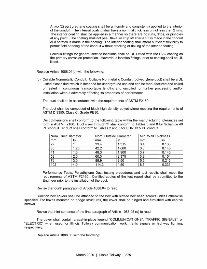
March 2020 | Illinois Tollway | 275
A two (2) part urethane coating shall be uniformly and consistently applied to the interior of the conduit. The internal coating shall have a nominal thickness of not less than 2 mils. The interior coating shall be applied in a manner so there are no runs, drips, or pinholes at any point. The coating shall not peel, flake, or chip off after a cut is made in the conduit or a scratch is made in the coating. The interior coating shall afford sufficient flexibility to permit field bending of the conduit without cracking or flaking of the interior coating.
Ferrous fittings for general service locations shall be UL Listed with the PVC coating as the primary corrosion protection. Hazardous location fittings, prior to coating shall be UL listed.
Replace Article 1088.01(c) with the following: (c) Coilable Nonmetallic Conduit. Coilable Nonmetallic Conduit (polyethylene duct) shall be a UL
Listed plastic duct which is intended for underground use and can be manufactured and coiled
or reeled in continuous transportable lengths and uncoiled for further processing and/or
installation without adversely affecting its properties of performance.
The duct shall be in accordance with the requirements of ASTM F2160. The duct shall be composed of black high density polyethylene meeting the requirements of ASTM D 3350, Class C, Grade PE30. Duct dimensions shall conform to the following table within the manufacturing tolerances set forth in ASTM F2160. Duct sizes through 3” shall conform to Tables 3 and 8 for Schedule 40 PE conduit. 4” duct shall conform to Tables 2 and 5 for SDR 13.5 PE conduit.
Nom. Duct Diameter Nom. Outside Diameter Min. Wall Thickness mm In mm in mm in 27 1 33.4 1.315 3.4 0.133 35 1.25 42.2 1.660 3.6 0.140 41 1.5 48.3 1.900 3.7 0.145 53 2.0 60.3 2.375 3.9 0.154 76 3.0 88.9 3.50 5.5 0.216 102 4.0 114.3 4.50 8.5 0.333
Performance Tests. Polyethylene Duct testing procedures and test results shall meet the requirements of ASTM F2160. Certified copies of the test report shall be submitted to the Engineer prior to the installation of the duct.
Revise the fourth paragraph of Article 1088.04 to read: Junction box covers shall be attached to the box with slotted hex head screws unless otherwise
specified. For boxes mounted on bridge structures, the cover shall be hinged and furnished with captive screws.
Revise the third sentence of the first paragraph of Article 1088.05 (c) to read: The cover shall contain a cast-in-place legend “COMMUNICATIONS”, “TRAFFIC SIGNALS”, or
“ELECTRIC” when used for Illinois Tollway communication work, traffic signals or highway lighting, respectively.
Replace Article 1088.06 with the following:
March 2020 | Illinois Tollway | 276
1088.06 Handhole Frame and Cover. Illinois Tollway heavy duty handholes shall be installed in all paved and un-paved areas. The cast iron frame and cover for Illinois Tollway heavy duty handholes shall be Neenah Foundry R-6662-PS with Type G lifting handle, East Jordan Iron Works No. EJ 8216 with MPIC or an approved equal.
March 2020 | Illinois Tollway | 277
Illinois State Toll Highway Authority
SUPPLEMENTAL SPECIFICATION FOR
SECTION 1094. OVERHEAD SIGN STRUCTURES
Issued April 1, 2016
This Supplemental Specification amends and supersedes the provisions of the Illinois Department of Transportation Standard Specifications for Road and Bridge Construction, adopted April 1, 2016 and shall be construed to be a part thereof, superseding any conflicting provisions thereof applicable to the work under the contract.
Section 1094 of the Standard Specifications for Road and Bridge Construction, adopted April 1, 2016 shall be modified as follows:
1094.02 Anchor Rods, Nuts, and Washers. Add the following paragraph to this Article: “Before or after threading, but before galvanizing, each anchor bolt shall be ultrasonically tested (UT) by a Level II or Level III inspector, qualified according to ANSI guidelines, to ensure no rejectable flaws exist in the upper 18” (tension criteria).”
March 2020 | Illinois Tollway | 278
Illinois State Toll Highway Authority
SUPPLEMENTAL SPECIFICATION FOR
SECTION 1103. PORTLAND CEMENT CONCRETE EQUIPMENT
Issued April 1, 2016
This Supplemental Specification amends and supersedes the provisions of the Illinois Department of Transportation Standard Specifications for Road and Bridge Construction, adopted April 1, 2016 and shall be construed to be a part thereof, superseding any conflicting provisions thereof applicable to the work under the contract.
Section 1103 of the Standard Specifications for Road and Bridge Construction, adopted April 1, 2016 shall be modified as follows:
1103.16 Formless Paver. Add the following paragraph to this Article:
“Compact Dowel Bar Inserters shall insert dowel bars into plastic concrete which has been placed and consolidated to full depth. The bars shall be inserted ahead of the finishing beam or screed and the installing device shall so consolidate the concrete that no voids exist around the dowel bars. The forward movement of the finishing beam or screed shall not be interrupted by the inserting of the dowel bars.”
March 2020 | Illinois Tollway | 279
Illinois State Toll Highway Authority
SUPPLEMENTAL SPECIFICATION FOR
SECTION 1201. TRAILER MOUNTED FULL MATRIX PORTABLE CHANGEABLE MESSAGE SIGN
Issued April 1, 2016
Revised March 23, 2020
This Supplemental Specification amends and supersedes the provisions of the Illinois Department of Transportation Standard Specifications for Road and Bridge Construction, adopted April 1, 2016 and shall be construed to be a part thereof, superseding any conflicting provisions thereof applicable to the work under the contract.
Add the following new articles:
1201.01 Description. This work shall consist of furnishing, installing, maintaining, relocating and removing a TRAILER MOUNTED FULL MATRIX PORTABLE CHANGEABLE MESSAGE SIGN(s) at locations shown on the Plans and at locations as directed by the Engineer.
Acceptable Manufacturers of the Trailer Mounted Full Matrix Portable Changeable Message Signs
at the time of this bid are:
Vermac - Model: 1500-30IL Wanco - Model: WTMMB-SLL(A)IT
Solar Technology – Model MB-3048-ITA Addco –Model FM 7X5 IT
Note: Other manufactures may be available after the bid award. Contact the Illinois Tollway’s Fleet
Manager for more information. The system supplied shall satisfy all the requirements of this specification. All other sign models or manufacturers must have the sign pre-qualified and tested before signs can
be put into service. Testing must be completed BEFORE the contractor is required to have sign in operation. Contractors are to contact the Illinois Tollway’s Fleet Manager to schedule message sign pre-qualification testing. Only signs that have passed the pre-qualification testing will be allowed to be used on Illinois Tollway construction projects.
1201.02 General Requirements. The signs specifications shall fully meet the Illinois Tollway’s
standard Trailer Mounted Full Matrix specifications as established by the Illinois Tollway’s Fleet Unit. The trailer mounted portable message sign shall be solar powered, 12-volt, full matrix LED. The sign shall be of a modular design allowing sections of the sign to be replaced individually. The sign shall withstand 70 MPH winds when in normal operating configuration and be all weather capable/non-condensing.
Prior to deploying any message sign, the contractor must have each sign inspected by the Illinois
Tollway at the Central Shop location 3460 S. Finley Road, Downers Grove. The Illinois Tollway may at its discretion install various equipment on each sign. This equipment will remain the property of the Illinois Tollway and cannot be removed or altered. All signs will be marked by the Illinois Tollway with a unique identification number. At the end of the contract period the contractor is required to deliver any and all message signs to the Central Shop location to have the equipment and decals removed.
March 2020 | Illinois Tollway | 280
1201.03 Message Panel Requirements. The sign lift cylinder shall have all safety devices required for safe operation and holding of sign in the event of a hydraulic hose failure. The message panel shall be at least 130 inches (not to exceed 136” width) by 70 inches, have a minimum 156-inch fully raised sign height, and present a level appearance. The message panel shall be flat black for non-reflectivity, with an easily removable UV and impact resistant front sign panel/cover. The sign panel shall have full graphics capability, and shall be three lines, 18-inch font capable. The sign shall have a display matrix of 25/48 minimum, with a 30-degree viewing angle/cone minimum. Individual messages shall be capable of containing words and graphics, with multiple line or character appearance/timing, sequencing, on/off duration, controlled by row, character or word. The LED’s shall be visible from 1000 feet minimum on a clear day (100,000 hour rated). The sign shall have a lockable main power switch, 12-volt system meter, and battery charge ammeter.
1201.04 Message Programming & Software. On site programming shall be via a backlit onboard
controller to be stored in a lockable storage compartment. The onboard controller shall maintain 200 minimum preprogrammed commonly used messages as well as 100 minimum custom messages (including sequences) and retain downloaded graphics. The onboard controller shall perform custom calendar settings to allow the sign to change messages by date and time, and shall allow the operator to view messages, sequencing and timing without having to view it on the sign (WYSIWYG). The message sign operating software shall be NTCIP compliant, and must be compatible and functional with Illinois Tollway Traffic Management Center (TIMS) Sign Control Software. The sign software shall allow the TIMS Center Software to “ping” the sign and gain the sign information including the message running on the sign at the time it is “pinged”. All controlling functions of sign messaging shall be password protected. Sign shall display a low battery signal and switch to low power consumption automatically. Typical transportation industry graphics shall be included with controller/software. Communications to the TIMS center shall be through a CDMA/1XRTT modem that is IP addressable. The sign software shall have the capability of working with encrypted IP addresses as required by the Illinois Tollway’s TIMS operating software. The modem shall be approved by Verizon Wireless for use on their network.
Wireless antenna(s) shall be mounted on the highest available location and properly grounded to the
trailer. Antenna location shall be installed to maximize reception and transmission properties. The unit shall be equipped with a Grey Island Systems GPS/AVL WAAS transponder. Grey Island Systems contact: Chris Jackson 76 Stafford Street Suite 100 Toronto, Ontario M6J 2S1 Phone: (416) 248-9991 ext 312 Email: [email protected] The transponder and message sign data line service shall be provided by Verizon Wireless. The Bidder shall contact Verizon to establish data line service for each sign and GPS transponder. The contractor is responsible for establishing and maintaining data communication lines for the
message signs for the duration of this contract.
The Illinois Tollway reserves the right to operate the sign via the Illinois Tollway’s TIMS Center which may take over control the sign(s) remotely. The TIMS Center’s control over what messages are being posted on the sign shall override any other entities or persons. The contractor may be required to notify the TIMS center of all messages being placed on the signs by them or their agent. The Contractor must notify the TIMS Center if a sign(s) is inoperable for any reason. The contractor may be required to regularly update the TIMS Center on the sign(s) location. The Illinois Tollway may move or alter the location of the sign at its discretion. The message sign operating software shall be National Transportation Communication Infrastructure Protocol (NTCIP) compliant and must be compatible and functional with Illinois Tollway Traffic Operation Center (TOC) Sign Control Software.
March 2020 | Illinois Tollway | 281
1201.05 Electrical Requirements. The message sign shall include automatic dimming to optimally
match ambient light conditions. Solar recharging of 12-volt batteries shall be via a moveable solar panel to maximize sun exposure. Batteries shall be capable of running the sign from full charge without recharging for 15 days minimum. Solar recharging of batteries shall allow continuous sign use during all weather conditions, year-round in northern Illinois regardless of the message size, shape, configuration or on time duration. The battery shall have a 1350-amp hour minimum storage capacity, and shall be 120-volt capable for full sign operation (in lieu of batteries). The message sign shall have onboard 120-volt to 12-volt self-regulating battery charger and a power supply capable of providing continuous uninterrupted service.
1201.06 Trailer Requirements. The trailer shall have four 2,000 lb rated leveling jacks/stabilizers and have a 3,500 lb capacity trailer axle with 15” radial tires with fenders. All external metal surfaces shall be powder coated in safety orange. All four sides of the trailer must have 100 inches minimum of DOT rated reflective red and white safety tape. The trailer lights and reflectors shall meet DOT standards. The trailer shall have a seven-pole pin type trailer light plug wired to DOT standards. The trailer shall have a lockable battery and compartment storage cover, an adjustable height pintle hitch with 3” eye opening, 3/8” safety chains and hooks, and a removable trailer tongue or hitch.
1201.07 Radar Display. The message sign shall be radar capable, drone type for traffic slow down
and reading style that will display actual traffic speed to approaching vehicles. Actual traffic speeds shall be viewable from TIM’s with an accuracy of plus or minus one MPH. Supply calibrating instruments on each trailer if required to calibrate radar.
1201.08 Message Display. The PCMS shall be visible from 3000 feet under both day and night
conditions. Each sign character shall be clearly legible from a minimum distance of 600 feet for nighttime conditions and 800 feet for normal daylight conditions. The message shall have adjustable display rates, so that the entire message can be read at least twice at the posted speed or the anticipated speed.
The bottom of the PCMS shall be a minimum of 7 feet above the roadway when operating. This height may be reduced to a minimum of 5 feet during high wind conditions to assure stability of the PCMS. The wheels of the PCMS shall be locked or blocked in order to prevent movement.
1201.09 Maintenance. Whenever signs are displaying messages they shall be considered a traffic
control device. At times when no messages are displayed, then they shall be considered equipment, and shall comply with Article 701.06(m).
1201.10 Interruption of Service. The Contractor shall provide all preventive efforts necessary to
achieve uninterrupted service. Upon notification by the Engineer, the Contractor shall respond by arriving at the sign location and commencing maintenance - failure to respond within 1/2 hour of said notification will result in the appropriate penalty, per Article 701.09(b). If service is interrupted for any cause and not restored to full operational service within twelve (12) hours, the defective sign shall be removed and a replacement sign shall be provided. If after 24 hours the defective sign has not been repaired or replaced, the Contractor shall be assessed a Non-Compliance with Specifications penalty, per Article 701.09(a).
1201.11 Documentation & Training. One service, parts and operators’ manual shall be provided with the message sign. The operator’s manuals shall include laminated abbreviated reminder sheet to assist operators in sign display. There shall be 4 hours of training per sign with a total not to exceed 16 hours for Illinois Tollway personnel.
1201.12 Method of Measurement. Trailer mounted full matrix portable changeable message signs will be measured for payment per each for each sign ordered, placed and accepted.
1201.13 Basis of Payment. Payment for TRAILER MOUNTED FULL MATRIX PORTABLE CHANGEABLE MESSAGE SIGNS will be made at the Contract unit price per each for trailer mounted full matrix changeable message sign ordered, placed, and accepted required for the duration of the Contract.
March 2020 | Illinois Tollway | 282
Payment for TRAILER MOUNTED FULL MATRIX PORTABLE CHANGEABLE MESSAGE SIGNS will be made at the Contract unit price per each per week for trailer mounted full matrix changeable message sign ordered, placed, and accepted required for one week duration.
Payment for TRAILER MOUNTED FULL MATRIX PORTABLE CHANGEABLE MESSAGE SIGNS will be made at the Contract unit price per each per month for trailer mounted full matrix changeable message sign ordered, placed, and accepted required for one month duration.
March 2020 | Illinois Tollway | 283
Payment for the sign shall constitute full compensation for furnishing, placing, maintaining, realigning, and relocating the trailer mounted full matrix portable changeable message sign as directed by the engineer, including the message sign warranty, for all labor, equipment, tools, and incidentals necessary to provide the portable changeable message signs as specified, and for providing documentation and training.
March 2020 | Illinois Tollway | 284
Illinois State Toll Highway Authority
SUPPLEMENTAL SPECIFICATION FOR
SECTION 1202. OPTION TO PURCHASE TRAILER MOUNTED FULL MATRIX PORTABLE CHANGEABLE MESSAGE SIGNS
Issued April 1, 2016
This Supplemental Specification amends and supersedes the provisions of the Illinois Department of Transportation Standard Specifications for Road and Bridge Construction, adopted April 1, 2016 and shall be construed to be a part thereof, superseding any conflicting provisions thereof applicable to the work under the contract.
Add the following new articles:
1202.01 Description. This work shall give the Illinois Tollway the option to purchase the TRAILER MOUNTED FULL MATRIX PORTABLE CHANGEABLE MESSAGE SIGN(S) that were provided as specified in Section1201.
Upon request of the Illinois Tollway, the Contractor shall provide a price per sign.
Contractors are to maintain all signs on Illinois Tollway construction projects in accordance with the message sign manufacturers recommend maintenance and repairs practices. The sign(s) shall include a three-month warranty after the sign(s) are purchased by the Illinois Tollway. The cost of the warranty shall be included in the price per sign provided by the Contractor. Any signs purchased by the Illinois Tollway shall be no more than four years old on the date of final acceptance of the Contract and in very good condition with all components of the sign working as designed by the manufacturer. The Illinois Tollway will only purchase signs when the construction contract is 18 months or more in duration.
1202.02 Method of Measurement. OPTION TO PURCHASE TRAILER MOUNTED FULL MATRIX
PORTABLE CHANGEABLE MESSAGE SIGNS will be measured for payment per each for each sign ordered, delivered and accepted.
1202.03 Basis of Payment. Payment for OPTION TO PURCHASE TRAILER MOUNTED FULL
MATRIX PORTABLE CHANGEABLE MESSAGE SIGNS will be made at the Contract unit price per each for each trailer mounted portable changeable message sign ordered, delivered, and accepted, which payment shall constitute full compensation for furnishing and delivering the trailer mounted portable changeable message sign, and for all labor, equipment, tools, and incidentals necessary to provide the portable changeable message signs as specified. The payment shall also include the cost of a three-month on-site warranty measured from the date of purchase.
March 2020 | Illinois Tollway | 285
Illinois State Toll Highway Authority
SUPPLEMENTAL SPECIFICATION FOR
SECTION 1203. SLOTTED PAVEMENT DRAINS
Issued April 1, 2016
This Supplemental Specification amends and supersedes the provisions of the Illinois Department of Transportation Standard Specifications for Road and Bridge Construction, adopted April 1, 2016 and shall be construed to be a part thereof, superseding any conflicting provisions thereof applicable to the work under the contract.
Add the following new articles: 1203.01 Description. This work shall consist of furnishing and installing slotted drain pipe
assemblies complete with all necessary fittings in the roadway pavement, ramp gores, and other locations as indicated in the Plans and directed by the Engineer.
The requirements for SLOTTED PAVEMENT DRAIN (RETROFIT) shall apply when any such drain is to be installed where saw cutting and removal of existing mainline, shoulder or gore paving is required.
The requirements for SLOTTED DRAIN (ORIGINAL) shall apply when any such drain is installed where saw cutting and removal of existing mainline, shoulder or gore paving is not required.
1203.02 Materials. All materials shall conform to the following Articles of Division 1000 - Materials of the Standard Specifications. Specific references are as follows:
Item Section/Article Concrete ......................................................................................... 1020
Slotted drain pipe assemblies shall be fabricated from 12-inch diameter coated corrugated steel pipe meeting the requirements of AASHTO M 36 (Type I), AASHTO M 218 or AASHTO M 190 (Type C). Each pipe section shall be slotted on one side and fitted with parallel vertical steel plates 1/8 inch or more in thickness and varying in height in accordance with the Plan details. The parallel plates shall be separated by not more than 2 inches and fitted with a suitable grating to allow the in-flow of water. The slot and grate shall be designed such that the in-flow capacity of the opening is greater than the flow capacity of the pipe at the gradient shown in the Plan details. The coating and paved invert shall be applied after fabrication.
1203.03 General Requirements. Slotted Pavement Drains shall be constructed in accordance with the applicable provisions of Section 550 of the Standard Specifications, and as herein required.
Slotted drain pipe assemblies shall be installed in accordance with the manufacturer’s specifications in a suitable trench and encased in Class SI concrete in accordance with the Plan details. When installed, the slotted drain shall conform to the alignment and gradient shown in the Plans. The complete slotted drain installation shall be designed to meet the requirements for AASHTO HS-20 loading.
Each slotted drain shall be connected to an existing or proposed drainage inlet with suitable fitting(s) and coupling band(s) as shown in the details.
The depth of the vertical riser will vary to accommodate the differential of gradient between the pavement surface and the slotted drain invert. The actual depth shall be as shown in the Plan details.
March 2020 | Illinois Tollway | 286
1203.04 Construction Requirements. For SLOTTED PAVEMENT DRAIN (RETROFIT) the existing paving shall be saw cut full depth, removed and disposed of by the Contractor.
Each slotted drain pipe assembly of either description shall be installed in a properly excavated trench, all connections assembled and tightened, the assembly rigidly blocked and supported in place to maintain alignment and gradient and the trench backfilled with Class SI Concrete.
Prior to backfilling, the slotted opening shall be covered to prevent the intrusion of foreign material during backfilling and paving operations.
Connections of outlet pipes into drainage structures as detailed shall be sealed with Class SI concrete collars to the satisfaction of the Engineer. Connections shall include all necessary fittings and miscellaneous hardware,
Any bituminous coating damaged in shipment, during installation, or prior to final acceptance shall be repaired by the Contractor to the satisfaction of the Engineer at no additional cost to the Illinois Tollway.
1203.05 Shop Drawings. The Contractor shall submit complete shop drawings detailing the type of slotted drain to be used and the construction techniques to be utilized in its installation. This submittal shall conform to the requirements of Article 105.04(d). In addition, the Contractor shall submit (10) copies of design calculations which substantiate structural properties of the proposed installation.
No work on this item shall be allowed until the required submittals have been made and approved by the Engineer.
1203.06 Method of Measurement. This work will be measured in units of feet of either description, complete in place and accepted.
1203.07 Basis of Payment. Payment for SLOTTED PAVEMENT DRAIN (RETROFIT) will be made at the Contract unit price per foot.
Payment for SLOTTED PAVEMENT DRAIN (ORIGINAL) will be made at the Contract unit price per foot.
March 2020 | Illinois Tollway | 287
Illinois State Toll Highway Authority
SUPPLEMENTAL SPECIFICATION FOR
SECTION 1204. PIPE RUNNERS
Issued April 1, 2016
This Supplemental Specification amends and supersedes the provisions of the Illinois Department of Transportation Standard Specifications for Road and Bridge Construction, adopted April 1, 2016 and shall be construed to be a part thereof, superseding any conflicting provisions thereof applicable to the work under the contract.
Add the following new articles:
1204.01 Description. This work shall consist of furnishing, fabricating, delivering and installing struc-tural steel pipe runners for pipe headwalls and safety end treatments in conformance with the Plans and Specifications or as directed by the Engineer. This shall include all anchor pipes, anchor pipe assemblies, support pipes, structural steel and all hardware necessary to construct and install the pipe runners
1204.02 Materials. Materials for the pipe runners shall conform to the following requirements: (a) Structural Steel .......................................................................... AASHTO M183 (b) Bolts ........................................................................................... ASTM A307, Grade A (c) Nuts ............................................................................................. ASTM A563 (AASHTO M291)
Grade A, Hex (d) Washers ..................................................................................... ASTM F844 (e) Steel Pipe .................................................................................... ASTM A53, Type E or S, Grade
B or ASTM A500, Grade B
1204.03 General Requirements. The work under this item shall conform to the applicable requirements of Section 505 of the Standard Specifications, except as herein modified.
Replace Article 505.06 with the following:
“Cleaning and Shop Painting, and substitute therefore: After fabrication is completed, the pipe runners and steel pipe components, structural steel, and hardware shall be galvanized in accordance with ASTM A123 (AASHTO M111) and A385. The zinc coating shall be applied at the average rate of not less than 2.1 ounces per square foot and no single sample shall show less than 1.8 ounces.”
Shop drawings shall be submitted in accordance with the requirements of Article 505.03 of the Standard Specifications.
1204.04 Method of Measurement. This work will be measured for payment in feet, completed and in place as shown in the Plans and to the satisfaction of the Engineer. The length measured for payment shall include all lengths of all pipe, anchor pipe assemblies and support pipes.
1204.05 Basis of Payment. This work will be paid at the contract unit price per foot for PIPE RUNNERS of the Diameter and Schedule specified.
March 2020 | Illinois Tollway | 288
Illinois State Toll Highway Authority
SUPPLEMENTAL SPECIFICATION FOR
SECTION 1206. HEADWALL GRATES
Issued April 1, 2016
This Supplemental Specification amends and supersedes the provisions of the Illinois Department of Transportation Standard Specifications for Road and Bridge Construction, adopted April 1, 2016 and shall be construed to be a part thereof, superseding any conflicting provisions thereof applicable to the work under the contract.
Add the following new articles:
1206.01 Description. This work shall consist of furnishing, fabricating, delivering, and installing structural steel headwall grates as shown on the Plans.
1206.02 General Requirements. The work and materials under this item shall conform to the applicable requirements of Section 505 of the Standard Specifications, except as herein modified.
Replace Article 505.06 of the Standard Specifications with the following:
“Cleaning and Shop Painting, and substitute therefore: After fabrication is completed, the headwall grates shall be galvanized in accordance with ASTM A153 (AASHTO M232). The zinc coating shall be applied at the average rate of not less than 2.10 ounces per square foot and no single sample shall show less than 1.8 ounces”.
Shop Drawings shall be submitted in accordance with the requirements of Article 505.03 of the Standard Specifications.
1206.03 Method of Measurement. This work will be measured for payment in pounds, completed in place and accepted.
1206.04 Basis of Payment. This work will be paid at the Contract unit price per pound for HEADWALL GRATES.
March 2020 | Illinois Tollway | 289
Illinois State Toll Highway Authority
SUPPLEMENTAL SPECIFICATION FOR
SECTION 1207. ENERGY ATTENUATOR
Issued April 1, 2016 Revised March 23, 2020
This Supplemental Specification amends and supersedes the provisions of the Illinois Department of Transportation Standard Specifications for Road and Bridge Construction, adopted April 1, 2016 and shall be construed to be a part thereof, superseding any conflicting provisions thereof applicable to the work under the contract.
Add the following new articles:
1207.01 Description. This work shall consist of furnishing, assembling and installing manufactured energy attenuators at locations as shown on the Plans and as directed by the Engineer. Work under this Section may also include the removal and proper disposal of existing energy attenuators as shown on the Plans and/or as directed by the Engineer.
1207.02 Materials. The energy attenuators shall be SCI Smart Cushion® TL-3, Model No. SCI100GM as manufactured by Work Area Protection Corp or approved equal. Should the Plans or Special Provisions permit an alternative to the aforementioned, such alternative shall be a resettable, fully redirective, bi-directional, non-gating system which has an approved FHWA MASH letter outlining the successful passing of MASH tests 3-30 through 3-38 and be approved by the Chief Engineering Officer.
Other materials shall conform to the requirements of Division 1000, Materials, of the Standard Specifications unless otherwise specified on the Plans. Specific references are:
Item Article/Section (a) Concrete (Class SI)..................................................................... 1020.04 (b) Reinforcing Steel......................................................................... 1006.10 (a) (1) (c) Epoxy Coating of Reinforcing Steel ............................................ 1006.10 (a) (2)
1207.03 Attenuator Removal. At locations, where an existing attenuator is to be removed, the Engineer and Illinois Tollway Maintenance personnel will inspect the existing attenuator(s) and determine whether it is salvageable.
Note: All existing attenuators when impacted by construction or damaged by motorist which do not meet MASH or NCHRP 350 requirements, will be deemed unsalvageable.
Unsalvageable attenuators shall become the property of the Contractor to be removed and properly disposed of outside the Illinois Tollway right-of-way. Salvageable attenuators shall be carefully removed by the Contractor, to prevent damage to the units, and delivered intact to the Illinois Tollway Maintenance facility designated in the Special Provisions. Any salvageable attenuators damaged by the Contractor during removal or transit shall be repaired and/or replaced to the satisfaction of the Engineer, at no additional cost to the Illinois Tollway.
Removal operations shall include saw cutting as shown on the Plans in accordance with the applicable provisions of Section 442 of the Standard Specifications. All other material removed as part of the removal of the attenuator shall be disposed of in accordance with Article 202.03 of the Standard Specifications.
March 2020 | Illinois Tollway | 290
Replacement parts necessary to repair the attenuator documented in MASH Test 3-31, shall be furnished and delivered to the Illinois Tollway Maintenance facility designated in the Special Provisions.
1207.04 Construction Requirements. The Contractor shall submit copies of the manufacturer's specifications and installation details for the Engineer's review. Unless otherwise stated, submittal requirements shall be per Article 105.04(d). Submittal requirements shall include details for the concrete pad and transition units as detailed in the plans.
When an attenuator is installed as part of new construction, the location shall be prepared in accordance with the Plans, as well as any recommendations from the manufacturer. If required by the manufacturer, the concrete pad and transition units shall be constructed in accordance with the applicable provisions of Sections 503 and 508 of the Standard Specifications, as well as the manufacturer's recommendations.
When an attenuator is installed on an existing Illinois Tollway facility, any existing pavement, shoulder and/or concrete median barrier and base shall be saw cut, removed and properly disposed of according to Article 202.03 of the Standard Specifications. Any restoration of the granular sub-base shall be performed in accordance with Section 311 of the Standard specifications.
The assembly and installation of the energy attenuator shall be in accordance with the manufacturer's recommendations.
1207.05 Method of Measurement. The work for ENERGY ATTENUATOR will be measured in units of each.
The work for ENERGY ATTENUATOR CONCRETE PAD will be measured in square feet.
The work for ENERGY ATTENUATOR REMOVAL will be measured in units of each.
CONCRETE BARRIER REMOVAL will be measured for payment in feet along the center of the concrete barrier wall.
1207.06 Basis of Payment. The work for ENERGY ATTENUATOR will be paid at the contract unit price per each.
The work for ENERGY ATTENUATOR CONCRETE PAD will be paid for at the contract unit price per square foot.
The work for ENERGY ATTENUATOR REMOVAL will be paid for at the contract unit price per each.
The work for CONCRETE BARRIER REMOVAL will be paid for at the contract unit price per foot.
March 2020 | Illinois Tollway | 291
Illinois State Toll Highway Authority
SUPPLEMENTAL SPECIFICATION FOR
SECTION 1208. BRIDGE DECK DRAINAGE
Issued April 1, 2016 Revised May 1, 2017
This Supplemental Specification amends and supersedes the provisions of the Illinois Department of Transportation Standard Specifications for Road and Bridge Construction, adopted April 1, 2016 and shall be construed to be a part thereof, superseding any conflicting provisions thereof applicable to the work under the contract.
Add the following new articles:
1208.01 Description. This work shall consist of furnishing and installing scupper castings and steel, PVC drain pipe and fittings for bridge deck drainage, cleaning, adjusting, sealing, or removing existing scuppers, removing, replacing or cleaning and painting existing drain pipe and fittings, all as shown in the Plans and in accordance with these Specifications. Also included shall be furnishing and installing steel slip plates required to properly position and support the scuppers during concrete placement and all galvanized inserts, grout, expansion anchors, threaded rods, nuts, washers, straps, structural steel shapes and miscellaneous hardware to properly install and support the drain pipe.
The work shall also include furnishing and installing splash blocks where required in accordance with these Specifications and with the dimensions and details shown in the Plans.
1208.02 Materials. Materials for scuppers and drains shall conform to the requirements of Division 1000 Materials of the Standard Specifications. Specific references are as follows:
Item Article/Section Concrete Superstructure ......................................................1020 Reinforcing Bars ...................................................................1006.10 Gray Iron Castings ................................................................1006.14 Structural Steel .....................................................................1006.04 Steel Pipe ..............................................................................1006.18 Structural Steel Coatings ................................................... 1008 Polyvinyl Chloride (PVC) Pipe (Note 1) ............................ 1040.03 Threaded Rods .....................................................................1006.09 H.S. Steel Bolts and Washers ..............................................1006.08 Note 1. PVC Pipe, when called for, shall be Schedule 80
1208.03 Construction Methods
(a) Installing Scuppers and Drain Pipe. The scuppers shall be placed and properly positioned in accordance with details and to the lines, grades and dimensions shown in the Plans.
The drain pipe and fittings shall be installed and securely fastened to the structure as shown in the Plans. All pipe joints shall be watertight and shall be of the type shown in the Plans.
Downspouts shall be provided with splash blocks, or shall be connected to storm sewers or subsurface drains as indicated in the Plans and directed by the Engineer. Pre-cast concrete splash blocks from a commercial supplier will be accepted without testing or certification.
After installation of scuppers and drain pipe, all exposed steel pipe and all miscellaneous hardware
March 2020 | Illinois Tollway | 292
not hot dipped galvanized shall be cleaned and painted in accordance with the applicable provisions of Section 506 of the Standard Specifications. All paint shall conform to the requirements of Section 1008 of the Standard Specifications.
(b) Adjusting Existing Scuppers. This work shall consist of furnishing and installing material, including adjusting frames, and performing all work required to raise or lower the grates of the existing scuppers, as shown in the Plans.
Adjusting frames shall be made in two sections as shown in the Plans and shall be furnished by the Contractor. Material for adjusting frames shall conform to AASHTO M105, Class 30 or ASTM A36 (AASHTO M183).
The inside flange of the existing frame shall be cleaned and free of foreign material. The inner section of the adjusting frame is to be placed on this flange. Shims shall be brazed to the frame to assure that rocking does not occur. The upper section of the adjusting frame shall be placed directly on the top of the existing frame and brazed to it as shown in the Plans. If a satisfactory fit is not obtained, grinding as necessary and/or additional brazing will be required at no additional cost to the Illinois Tollway.
(c) Sealing Existing Scuppers. This work shall consist of sealing with concrete those existing scuppers which are not to remain in service, as shown in the Plans and as directed by the Engineer. To seal any scupper, the lower flange of the casting shall be suitably capped and the entire scupper casting filled with thoroughly consolidated concrete. Salvageable grates which are not to be reused shall be delivered to the Illinois Tollway Maintenance Yard designated in the Plans.
(d) Removing Existing Scuppers. This work shall consist of removing existing scuppers which are not to remain in service and reconstructing the bridge deck as shown in the Plans and as directed by the Engineer. The work shall include saw cutting and removing the bridge deck concrete as shown in the Plans, blast-cleaning the existing reinforcing steel, furnishing and installing supplemental reinforcing steel, and furnishing and placing Class J Concrete.
Salvageable grates and scupper castings which are not to be re-used shall be delivered to the Illinois Tollway’s Maintenance Yard designated in the plans.
Concrete removal shall be in accordance with Section 501 of the Standard Specifications.
After the existing concrete has been removed and the reinforcing steel has been cleaned, the Engineer will inspect the concrete surfaces. Any and all loose and unsound concrete found by such inspection shall be removed, using hand tools, to the satisfaction of the Engineer prior to the placement of concrete.
Placement of concrete shall be in accordance with the applicable portions of Section 503 of the Standard Specifications.
Furnishing and installing supplemental reinforcing steel shall be in accordance with the applicable portions of Section 508 of the Standard Specifications.
(e) Removing Existing Drain Pipe. This work shall consist of removing existing drain pipe at locations where the pipe is no longer necessary due to sealing or removal of existing scuppers and at other locations as shown in the Plans or directed by the Engineer.
The removal shall include all miscellaneous hardware, straps and miscellaneous supports. Salvageable drain pipe and fittings shall be delivered to the Authorities Maintenance Yard designated in the plans. Unsalvageable pipe and all other material removed shall be disposed of in accordance with Article 202.03 of the Standard Specifications.
March 2020 | Illinois Tollway | 293
Where existing drain pipe is to be removed from scuppers which are to remain in service, the flanges of the existing scuppers shall be protected from damage.
(f) Cleaning and Painting Drain Pipe. This work shall consist of cleaning, painting, and refurbishing existing bridge deck drainage systems as indicated in the Plans and as directed by the Engineer, all in accordance with applicable portions of Section 560 of the Standard Specifications and the applicable Articles of this Section.
Where separations at existing fittings or other misalignments are found, repairs or corrections shall be made as necessary to restore the bridge drain piping to a fully functioning system.
All horizontal and vertical runs of pipe shall be power rodded and flushed. Flushing shall be done in conjunction with power rodding to assure that pipes are in a satisfactorily clean condition. All existing end caps shall be removed to facilitate power rodding of horizontal runs of pipe. Should any existing end cap unit be damaged by the Contractor’s operations, it shall be replaced at no additional cost to the Illinois Tollway with a P.V.C. Schedule 80 end cap unit of the same size.
Any existing pipe or fittings found, in the judgment of the Engineer, to be deteriorated beyond further functional service, shall be removed and replaced with new pipe or fittings. Replacement pipe shall be steel pipe conforming to the requirements of Article 1006.18 of the Standard Specifications or Schedule 80 PVC pipe conforming to the requirements of Article 1040.03 of the Standard Specifications as directed by the Illinois Tollway. Removal of deteriorated pipe shall be measured and paid for under REMOVE EXISTING DRAIN PIPE. Replacement of deteriorated pipe will be measured and paid for under the applicable type and size of DRAIN PIPE.
Existing splash blocks under downspouts which are sunken or displaced shall be re-set as directed by the Engineer. The ground surface around and downstream from splash blocks shall be re-shaped as necessary to drain water away from the downspouts and into existing ditches or surface drainage systems without channeling or causing surface erosion.
Damaged or missing splash blocks shall be replaced at locations designated in the Plans or as directed by the Engineer. Pre-cast concrete splash blocks from a commercial supplier will be accepted without testing or certifications.
Re-setting and replacing splash blocks and re-shaping ground surface areas at downspouts will not be measured for payment. The cost therefore shall be considered as included in the Contract unit price for CLEAN AND PAINT EXISTING DRAIN PIPE.
(g) Cleaning Existing Scupper. This work shall consist of cleaning existing scuppers at the locations shown in the plans or as directed by the Engineer.
All existing scuppers shall be inspected by the Contractor together with the Engineer prior to starting construction and a record kept of their condition. All debris which accumulates in the existing scuppers during construction shall be removed and disposed of by the Contractor at no additional cost to the Illinois Tollway. The Contractor shall remove all debris and silt from the designated scuppers and flush them out with water.
(h) Replacing Existing Scupper Grate. This work shall consist of removing and replacing damaged or missing scupper grates at the locations shown in the plans or as directed by the Engineer. All existing scuppers shall be inspected by the Contractor together with the Engineer prior to starting construction and a record kept of their condition. Any damage to existing scuppers or grates during construction shall be repaired to the satisfaction of the Engineer by the Contractor at no additional cost to the Illinois Tollway.
(i) Floor Drain. This work shall include furnishing and installing floor drains and all other hardware including galvanized steel threaded rods, clamps, washers and locknuts at the locations shown in the plans.
March 2020 | Illinois Tollway | 294
1208.04 Method of Measurement
SCUPPER will be measured for payment per each furnished installed, and accepted, for each type specified.
DRAIN PIPE will be measured for payment in feet, furnished installed and accepted, for each type and for the various sizes specified. Measurement will be along the centerline of each run of pipe from end to end. Fittings will not be measured separately for payment, but will be considered as included in the measurement for Drain Pipe.
ADJUST EXISTING SCUPPER, SEAL EXISTING SCUPPER, REMOVE EXISTING SCUPPER, CLEAN EXISTING SCUPPER and REPLACE EXISTING SCUPPER GRATE will be measured for payment in units of each completed and accepted.
REMOVE EXISTING DRAIN PIPE will be measured for payment in feet of pipe removed and salvaged or otherwise disposed of as specified. Measurement will be along the centerline of each run of pipe removed, from end to end. CLEAN AND PAINT EXISTING DRAIN PIPE will be measured for payment in feet of pipe cleaned, refurbished and painted as specified.
Splash blocks and re-shaping of ground surfaces will not be measured for payment.
FLOOR DRAIN will be measured for payment in units of each furnished installed and accepted.
1208.05 Basis of Payment
SCUPPER, measured as specified, will be paid at the Contract unit price per each.
DRAIN PIPE, measured as specified, will be paid at the Contract unit price per foot for the type and size specified.
ADJUST EXISTING SCUPPER, measured as specified, will be paid at the Contract unit price per each.
SEAL EXISTING SCUPPER, measured as specified, will be paid at the Contract unit price per each.
REMOVE EXISTING SCUPPER, measured as specified, will be paid at the Contract unit price per each.
REMOVE EXISTING DRAIN PIPE, measured as specified, will be paid at the Contract unit price per foot.
CLEAN EXISTING SCUPPER, measured as specified, will be paid at the Contract unit price per each.
REPLACE EXISTING SCUPPER GRATE, measured as specified, will be paid at the Contract unit price per each.
CLEAN AND PAINT EXISTING DRAIN PIPE, measured as specified, will be paid at the Contract unit price per foot.
FLOOR DRAIN, measured as specified, will be paid at the Contract unit price per each.
March 2020 | Illinois Tollway | 295
Illinois State Toll Highway Authority
SUPPLEMENTAL SPECIFICATION FOR
SECTION 1209. RESET BRIDGE EXPANSION BEARINGS
Issued April 1, 2016
This Supplemental Specification amends and supersedes the provisions of the Illinois Department of Transportation Standard Specifications for Road and Bridge Construction, adopted April 1, 2016 and shall be construed to be a part thereof, superseding any conflicting provisions thereof applicable to the work under the contract.
Add the following new articles:
1209.01 Description. This work shall consist of moving and resetting bridge expansion bearings to positions consistent with the ambient temperature prevailing at the time the bearings are placed under load in their new positions at the locations shown in the Plans and as directed by the Engineer. It shall include the necessary jacking operations, the reinforcing of the existing diaphragms or beam ends as required for jacking, removal of weldments or bolts, rewelding or rebolting in the final position of the bearings, and burning necessary slotted holes in bottom flanges.
1209.02 Materials. All materials shall conform to Materials, Division 1000 of the Standard Specifications.
1209.03 Construction Methods
(a) General. Sub-Section, Description shall govern. “JACK AND REMOVE EXISTING BEARINGS“ of IDOT, GBSP #14, as found therein shall be understood as “RESET BRIDGE EXPANSION BEARINGS”.
The following shall also apply to this item:
Before starting jacking operations, the relative elevations of the bottom flanges of the beam and girder ends shall be determined.
After replacing or resetting the expansion bearings, the beam and girders shall be lowered to the same elevations to ensure correct transfer of their reactions to the bearings.
Girders or beams supported by the bearings shall not be raised more than 1/4 inch at the point of support. Adjacent beams and girders shall be raised simultaneously such that the vertical differential between adjacent girders does not at any time exceed 1/8 inch. Suitable gages for the measurement of girder movement shall be furnished and installed by the Contractor.
(b) Working Drawings and Inspection. “Construction Requirements (a)” of IDOT, GBSP #14 shall govern.
1209.04 Bearing Adjustment. After jacking has been completed and all required bracing, shoring, or blocking is in place, the existing bearing assemblies shall be removed and re-positioned so that the angle or distance of movement from the neutral position coincides with the calculated thermal movement of the bridge superstructure for the ambient temperature prevailing at the time. The correct position for each bearing will be determined by the Engineer and each bearing shall be repositioned in strict accordance with the Engineer’s directions.
March 2020 | Illinois Tollway | 296
For bearings where weldments attach the top plate of the bearing assembly to the bottom flange of the beam or girder, removal of the weld between the plate and the flange shall be accomplished by the Air-Carbon Arc Gouging process. Procedures for this method of weld removal shall be in strict accordance with publication ANSI/AWS C3.5 “Recommended Practices for Air-Carbon Arc Gouging and Cutting” published by the American Welding Society, Inc. All weld removal and welding shall be accomplished by a qualified welder and shall meet the approval of the Engineer. Other methods of removal of the weld shall be prohibited. Welding of the top plate to the bottom flange after repositioning shall be accomplished in accordance with Article 505.04(q) of the Standard Specifications, or bolted in accordance with the details shown in the Plans, if any.
For bearings where the top plate of the bearing assembly is bolted to the bottom flange of the beam or girder, the bolts may be burned off by a method approved by the Engineer. After positioning the top plate in its final location on the bottom flange, the plate shall be welded in accordance with Article 505.04(q) of the Standard Specifications.
1209.05 Method of Measurement. This work will be measured for payment in units each, complete in place and accepted.
1209.06 Basis of Payment. This work will be paid at the contract unit price per each for RESET BRIDGE EXPANSION BEARINGS.
March 2020 | Illinois Tollway | 297
Illinois State Toll Highway Authority
SUPPLEMENTAL SPECIFICATION FOR
SECTION 1210. RESTORATION AND ADJUSTMENT OF BRIDGE BEARING PEDESTALS
Issued April 1, 2016
This Supplemental Specification amends and supersedes the provisions of the Illinois Department of Transportation Standard Specifications for Road and Bridge Construction, adopted April 1, 2016 and shall be construed to be a part thereof, superseding any conflicting provisions thereof applicable to the work under the contract.
Add the following new articles:
1210.01 Description. This work shall consist of removing and replacing deteriorated and unsound concrete in bridge bearing pedestals and/or raising or lowering the height of the pedestals to accommodate new bridge bearings, at the locations shown in the Plans and as directed by the Engineer.
1210.02 Materials. All materials shall conform to the requirements of Division 1000 of the Standard Specifications, Materials. Specific references are as follows:
IDOT GBSP 53 Structural Repair of Concrete, Materials
1210.03 Construction Methods
(a) Restoration of Pedestals. Where pedestals are to be restored, all loose, disintegrated and unsound concrete shall be removed completely using pneumatic tools or other equipment meeting the approval of the Engineer. The removal shall be to the depth necessary to reach sound concrete and the tools selected shall be of such size and weight that use of them will not damage sound concrete adjacent to the areas being repaired.
After removal of the unsound concrete, the remaining surfaces shall be blown free of all dust and loose particles by means of compressed air. A filter and oil trap shall be provided in the air line to prevent a film of oil from being deposited from the compressor. After the area has been blown clean, each surface of the area shall be inspected to assure that it is completely solid and that no unbonded particles remain trapped by or adhered to the reinforcing steel. Unbonded particles tend to be retained along partially exposed reinforcement bars and beneath fully exposed reinforcement bars. The Contractor shall give special attention to these areas during the final cleaning operations.
Upon completion of inspection and final surface preparation, a suitable form shall be placed around the pedestal and the removed concrete replaced with materials meeting the requirements of this Section.
Areas to be repaired to a depth of 2" or less shall be patched with materials meeting the requirements of ASTM C-928. Neat material shall be used in patches 1" or less in depth and shall be extended with aggregate in accordance with the manufacturer’s recommendations for depths greater than 1".
Areas greater than 2" in depth and up to the limit recommended by the manufacturer may be patched either with material meeting the requirements of ASTM C928 or Concrete Structures.
March 2020 | Illinois Tollway | 298
Areas where the depth exceeds the limit recommended by the manufacturer shall be patched with Concrete Structures.
When the replacement concrete has completely set, the form shall be removed and the work area thoroughly cleaned of all debris and dust.
Should it be found necessary, in the sole judgment of the Illinois Tollway, to remove and replace any bridge expansion bearing in order to adequately restore the pedestal, the removal and replacement of the bearing shall be accomplished in accordance with the provisions of this Section. If Item RESET BRIDGE EXPANSION BEARINGS is included in the Contract, measurement and payment for such removal and replacement will be in accordance with Section 1209. If this Item is not included in the Contract, such removal and replacement shall be accomplished as Extra Work with payment to be in accordance with the provisions of Article 109.04.
(b) Adjustment of Pedestals. In conjunction with restoration or alone, the height of each pedestal shall be raised or lowered as required to accommodate the new bearing assemblies. Raising of pedestals shall be accomplished by removing all loose, unsound, or deteriorated concrete, removing at least ¼ inch of sound concrete, thoroughly cleaning the exposed surfaces, placing a suitable form around the pedestal, and placing magnesium phosphate concrete or epoxy concrete at the Contractor’s option, or placing material as applicable per guidelines of Article 1201.03(a), to the required pedestal elevation. Lowering of pedestals shall be accomplished by removing all loose, unsound or deteriorated concrete, removing sound concrete to a level at least ½ inch below the required pedestal elevation, thoroughly cleaning the exposed surfaces, placing a suitable form around the pedestal, and placing magnesium phosphate concrete or epoxy concrete at the Contractor’s option, to the required pedestal elevation.
Each adjusted pedestal shall be reconstructed such that the finished pedestal surface is exactly parallel in all directions with the bottom flange of the beam or girder it will support and at an elevation which precisely accommodates the height of the new expansion bearing assembly in its final position. Tolerance shall be 1/8” plus or minus.
1210.04 Method of Measurement. This work will be measured for payment in units of each on the basis of the number of restorations and/or adjustments completed and accepted, in place.
1210.05 Basis of Payment. This work will be paid at the Contract unit price per each for RESTORATION AND ADJUSTMENT OF BRIDGE BEARING PEDESTALS.
March 2020 | Illinois Tollway | 299
Illinois State Toll Highway Authority
SUPPLEMENTAL SPECIFICATION FOR
SECTION 1211. ANCHORAGE INSTALLATION
Issued April 1, 2016
This Supplemental Specification amends and supersedes the provisions of the Illinois Department of Transportation Standard Specifications for Road and Bridge Construction, adopted April 1, 2016 and shall be construed to be a part thereof, superseding any conflicting provisions thereof applicable to the work under the contract.
Add the following new articles:
1211.01 Description. This work shall consist of installing dowel bars and/or anchor rods in existing Portland cement concrete at locations shown in the Plans or designated by the Engineer. The installation of anchor rods and dowels which are included for payment under any other pay item are not included in this work.
1211.02 Materials. Materials shall conform to the requirements of Division 1000 of the Standard Specifications, Materials of the IDOT Standard Specifications, unless otherwise specified on the plans. Specific references are:
Item Article/Section (a) Anchor Bolts and Threaded Rods............................................... 1006.09 (b) Concrete Reinforcement Bars .................................................... 1006.10 (c) Epoxy Grout ................................................................................ 1025.01 (d) Expansion Anchors ..................................................................... 1006.09 (e) Chemical Adhesive ..................................................................... 1027
1211.03 Construction Methods
(a) Drilling and Epoxy Grouting. Holes shall be drilled in the concrete to ¼ in. (6mm) larger in diameter of the anchor rods or bars and to the depth shown on the plans. A template or other approved method shall be used to assure accurate location of the drilled holes. All holes shall be blown free of concrete dust and chips and shall be absolutely dry prior to placing the epoxy grout.
Prior to inserting the anchor rod or bar into the hole, the hole shall be filled approximately 1/3 full of the mixed epoxy grout. The anchor rod or bar shall be inserted into the partially filled hole and moved up and down several times to insure total contact of the grout with concrete as well as the rod or bar. Additional grout shall be extruded to proper concrete level and finished as necessary. The anchor rod or bar shall be aligned to maintain a perpendicular plane. No load shall be applied to the anchors until the grout has cured for at least 24 hours.
(b) Drilling and Installing. Expansion Anchors, Dowel bars and anchor rods will be anchored by mechanical methods in accordance with recommendations of the manufacturer of the expansion device. Complete installation instructions, as well as manufacturer’s strength test support literature on the expansion devices that will be used, shall be supplied by the Contractor to the Engineer for approval.
The particular devices installed shall be as shown in the Plans or directed by the Engineer.
March 2020 | Illinois Tollway | 300
1211.04 Method of Measurement. This work will be measured for payment in units of each, regardless of size, for the number of dowel or anchor units installed, complete, in place and accepted. Steel components or assemblies required in the Plans or ordered by the Engineer will not be measured separately but will be considered integral with the dowel or anchor units required.
Anchor rods and dowel bars which are included in, or are measured for payment under any other payment item will not be measured for payment under this item.
1211.05 Basis of Payment. This work will be paid at the Contract unit price per each for DRILL AND GROUT DOWEL BARS AND ANCHOR RODS or DRILL AND INSTALL EXPANSION ANCHORS, DOWEL BARS AND ANCHOR RODS.
Separate payment will not be made for steel components required for this work. The cost therefore shall be considered as included in the Contract unit price for DRILL AND GROUT DOWEL BARS AND ANCHORS RODS or DRILL AND INSTALL EXPANSION ANCHORS, DOWEL BARS AND ANCHORS RODS.
March 2020 | Illinois Tollway | 301
Illinois State Toll Highway Authority
SUPPLEMENTAL SPECIFICATION FOR
SECTION 1212. LOW PRESSURE EPOXY INJECTION
Issued April 1, 2016
This Supplemental Specification amends and supersedes the provisions of the Illinois Department of Transportation Standard Specifications for Road and Bridge Construction, adopted April 1, 2016 and shall be construed to be a part thereof, superseding any conflicting provisions thereof applicable to the work under the contract.
Add the following new articles:
1212.01 Description. This work shall consist of the structural repair of cracks in Portland cement concrete and rebonding structural steel armor at the locations as shown in the Plans or as directed by the Engineer, and shall include the repair of all cracks except those specified under Section 1213. Repair shall be accomplished by low pressure injection of an epoxy resin adhesive. The repair of cracks in Portland cement concrete beams, girders and diaphragms shall be done in accordance with the provisions of Section 1213 of these Supplemental Specifications.
1212.02 Materials
(a) Adhesive. The adhesive used for injection shall be a moisture insensitive, low-viscosity, two-component, 100 percent solids epoxy-resin system conforming to Section 1025 of the Standard Specifications which is compounded for and specifically recommended by the manufacturer for pressure injection grouting of cracked Portland cement concrete. The product furnished shall meet the approval of the Engineer and shall be of the appropriate Class under ASTM C881 (AASHTO M235) for the atmospheric and concrete temperature conditions prevailing at time of placement.
(b) Surface Seal. The material used as a surface seal must have adequate strength and adhesion to confine the injection adhesive in the crack being repaired until the injected adhesive has cured. After the injected adhesive has cured, the surface seal must be removable.
(c) Injection Ports and Tubes. Injection ports shall be one-way polyethylene valves. These shall be provided with appropriate lengths of rubber or polyethylene tubing fitted with pinch-cock shutoffs. All ports and tubing shall be 1/4 inch O.D.
(d) Solvents. The Contractor shall maintain at the site of the work suitable chemical solvents for cleaning tools and equipment. Solvents shall be in clearly labeled containers.
(e) Certification. Prior to use of adhesive, the Contractor shall submit to the Engineer the manu-facturer’s certification that all proposed materials conform to the requirements herein. The Contractor shall also provide the manufacturer’s complete specifications on formulation and application of the materials and instructions on handling, mixing, and injecting, including detailed descriptions of equipment to be used.
(f) Packaging and Labeling. All epoxy resin materials shall be delivered to the site in clearly labeled, unopened containers. All labels shall clearly indicate:
March 2020 | Illinois Tollway | 302
(1) Name of manufacturer.
(2) Manufacturer’s product name or product number.
(3) Manufacturer’s lot number.
(4) Mix ratio.
(5) Conformance with ASTM C881 (AASHTO M235) including appropriate Type, Grade, and Class.
(6) Hazardous material rating and appropriate warnings for handling. This requirement shall also apply to the labeling of cleaning solvents.
(g) Mixing of Adhesive. The two components of the adhesive shall be mixed in accordance with the manufacturer’s instructions. The mixing operation shall be subject to the approval of the Engineer.
1212.03 Equipment. The equipment used to meter and mix the two adhesive components and inject the mixed adhesive into the crack shall be of the type recommended by the adhesive manufacturer and shall meet the approval of the Engineer. Injection equipment shall be kept thoroughly clean at all times.
1212.04 Construction Requirements
(a) General. Crack injection may proceed at any time the temperature of the concrete is 35°F or higher provided the appropriate Class of material under ASTM C881 (AASHTO M235) has been selected. Otherwise, crack injection shall proceed only when the temperature of the concrete is within the range established in ASTM C881 (AASHTO M235) for the Class of material supplied.
The Contractor shall have available at the beginning of the operations a representative of the manufacturer, experienced in the use of the epoxy.
The Contractor shall obtain from the epoxy manufacturer complete instructions as to the safety, health, and handling precautions that must be exercised with respect to the materials to be used, and as to the procedure that should be followed in the event that workers come in contact with the materials. Before they are permitted to proceed with the work, the workers shall be effectively instructed as to the hazards to which they will be exposed, the necessary safety precautions, and the procedure to be followed in case of accidental contact with the materials.
The two components of the epoxy adhesive shall be mixed in the injection equipment in the proportions recommended by the manufacturer. The Contractor shall carefully check the calibration of the injection equipment and certify to the Engineer in writing that the proportions are correct.
(b) Crack Preparation. The cracks to be repaired shall be cleaned of all dust, dirt, debris or any other foreign matter by oil-free high pressure compressed air and/or vacuuming or other methods which are approved by the Engineer. All cracks containing oil or grease must be chipped out to clean concrete. When required by the Engineer, cracks shall be water injected for thorough cleaning. The surfaces of the cracks shall be dry prior to the injection of the adhesive.
March 2020 | Illinois Tollway | 303
Concrete in areas adjacent to cracks to be repaired shall be sounded to determine the extent of any spalling, delamination, or other deterioration. Unsound concrete, as determined by sounding and as directed by the Engineer, shall be removed and the area repaired in accordance with the requirements of Sections IDOT, GBSP #4 or #53. Unsound concrete shall be removed but not replaced until the crack has been repaired in accordance with this Section.
The repair of unsound concrete adjacent to cracks which are to be repaired is not included in this item, but shall be accomplished, measured, and paid for in accordance with the provisions of IDOT, GBSP #4 or #53 as provided in the Contract or directed by the Engineer.
Prior to the injection of the adhesive, a surface seal material shall be applied to the face of the crack.
Entry ports (openings) in the surface seal shall be established along the crack. The distance between entry ports shall not be less than the thickness of the concrete member being repaired.
(c) Injection
(1) Cracks: Injection of the adhesive into each crack shall begin at the entry port at the lowest elevation. Injection shall continue at the first port until the injected adhesive begins to flow out of the port at the next higher elevation. The first port shall then be plugged and injection started at the second port and continued until the adhesive flows from the next succeeding port. This sequence shall be continued until the entire crack has been filled.
(2) Rebonding Steel Armor: For rebonding steel armor the application of a surface seal will not be required. Injection ports shall be installed in holes drilled entirely through the horizontal portion of the armor to be bonded. Injection holes shall be spaced as deter-mined by the Engineer from sounding. Injection shall begin at the port of the lowest elevation on the bridge deck cross-slope and shall continue at that port until the adhesive begins to flow from the next higher port. The first port shall then be plugged and injection started at the second port until the adhesive flows from the next succeeding port. This sequence shall be continued until all the ports have been filled.
In the event there is a sufficient flow of adhesive from beneath the steel armor that successive injection ports cannot be filled, injection shall be stopped and the leaks plugged with a two-component epoxy resin gel meeting the requirements for Grade 3 under ASTM C881 (AASHTO M235). Injection shall continue after the gel plugs have hardened. Placement of gel plugs may be by any means which proves effective. Plugging leaks as necessary shall be at no additional cost to the Illinois Tollway and without cause for the Contractor claiming delay.
(d) Finishing
(1) Cracks: After the injection adhesive has hardened the surface seal shall be removed. The face of the crack shall be ground flush with the adjacent concrete. Indentations or depressions shall be filled with Grade 3 epoxy gel and reground until the surface is smooth.
(2) Rebonding Steel Armor: After the injection adhesive has hardened the injection ports shall be removed and all protrusions ground smooth, flush with the steel surface. Indentations shall be filled with Grade 3 epoxy gel and reground until the surface is smooth.
March 2020 | Illinois Tollway | 304
1212.05 Method of Measurement. This work will be measured for payment in feet along each crack repaired or each steel armor assembly rebonded, complete, in place and accepted.
1212.06 Basis of Payment. This work will be will be paid at the Contract unit price per foot for LOW PRESSURE EPOXY INJECTION.
March 2020 | Illinois Tollway | 305
Illinois State Toll Highway Authority
SUPPLEMENTAL SPECIFICATION FOR
SECTION 1213. HIGH PRESSURE EPOXY INJECTION
Issued April 1, 2016
This Supplemental Specification amends and supersedes the provisions of the Illinois Department of Transportation Standard Specifications for Road and Bridge Construction, adopted April 1, 2016 and shall be construed to be a part thereof, superseding any conflicting provisions thereof applicable to the work under the contract.
Add the following new article:
1213.01 Description. This work shall consist of the structural repair of cracks in Portland cement concrete beams, girders and diaphragms as shown in the Plans or as directed by the Engineer. Repair shall be accomplished by high pressure injection of an epoxy resin adhesive. The repair of cracks in other concrete structural elements and the rebonding of structural steel armor shall be done in accordance with the provisions of Section 1212 of these Supplemental Specifications.
1213.02 Materials
(a) Adhesive. The adhesive used for injection shall be a moisture insensitive, low-viscosity, two-component, 100 percent solids epoxy resin system conforming to Section 1025 of the Standard Specifications which is compounded and specifically recommended by the manufacturer for pressure injection grouting of cracked Portland cement concrete. The product furnished shall meet with the approval of the Engineer and shall be of the appropriate Class under ASTM C881 (AASHTO M235) for the atmospheric and concrete temperature conditions prevailing at the time of placement.
(b) Surface Sealant. The surface sealant used shall be a non-sagging, two-component, 100 percent solids epoxy resin gel which is compounded and specifically recommended by the manufacturer for surface sealing prior to high pressure epoxy injection. The product shall meet with the approval of the Engineer, the requirements for Grade 3 under ASTM C881 (AASHTO M235), and shall be of the appropriate Class under ASTM C881 (AASHTO M235) for the atmospheric and concrete temperature conditions prevailing at the time of placement.
(c) Injection Ports and Tubes. Injection ports shall be one-way polyethylene valves. These shall be provided with appropriate lengths of rubber or polyethylene tubing fitted with pinch-cock shutoffs. All ports and tubing shall be 1/4 inch O.D.
(d) Solvents. The Contractor shall maintain at the site of the work suitable chemical solvents for cleaning tools and equipment. Solvents shall be in clearly labeled containers.
(e) Certification. Prior to the use of any epoxy resins the Contractor shall submit to the Engineer the manufacturer’s certification that all materials conform to the requirements herein. The Contractor shall also provide the manufacturer’s complete specifications on formulation and application of the materials and instructions on handling, mixing, and injecting, including detailed descriptions of equipment to be used.
(f) Packaging and Labeling. All epoxy resin materials shall be delivered to the site in clearly labeled, unopened containers. All labels shall clearly indicate:
March 2020 | Illinois Tollway | 306
(1) Name of manufacturer
(2) Manufacturer’s product name or product number
(3) Manufacturer’s lot number
(4) Mix ratio
(5) Conformance with ASTM C881 (AASHTO M235), including appropriate Type, Grade, and Class.
(6) Hazardous material rating and appropriate warnings for handling. This requirement shall also apply to the labeling of cleaning solvents.
1213.03 Equipment. Equipment for high pressure epoxy injection shall have the capability to precisely proportion the two epoxy resin components, thoroughly mix the two components, and inject the mixed epoxy resin at working pressures up to 1000 psi, all in a single, integrated, and continuous operation.
1213.04 Construction Procedures
(a) General. Crack injection may proceed at any time the temperature of the concrete is 35°F or higher provided the appropriate Class of material under ASTM C881 (AASHTO M235) has been selected. Otherwise, crack injection shall proceed only when the temperature of the concrete is within the range established in ASTM C881 (AASHTO M235) for the Class of material supplied.
The Contractor shall have available at the beginning of the operations a representative of the manufacturer, experienced in the use of the epoxy.
The Contractor shall obtain from the epoxy manufacturer complete instructions as to the safety, health, and handling precautions that must be exercised with respect to the materials to be used, and as to the procedure that should be followed in the event that workers come in contact with the materials. Before they are permitted to proceed with the work, the workers shall be effectively instructed as to the hazards to which they will be exposed, the necessary safety precautions, and the procedure to be followed in case of accidental contact with the materials.
The two components of the epoxy adhesive shall be mixed in the injection equipment in the proportions recommended by the manufacturer. The Contractor shall carefully check the calibration of the injection equipment and certify to the Engineer in writing that the proportions are correct.
(b) Crack Preparation. At each crack to be repaired, holes of the correct diameter to accept the injection ports shall be drilled into the concrete, centered on the crack, at a spacing of 6 to 12 inches depending on crack width and length. Depth of the holes shall be 11/2 to 21/2 inches.
After drilling injection holes the cracks shall be cleaned of all dust, dirt, debris or any other foreign matter by oil-free compressed air and/or vacuuming, or other methods which are approved by the Engineer. All cracks containing oil or grease must be chipped out to clean concrete. When required by the Engineer, cracks shall be water injected for thorough cleaning. The surfaces of the cracks shall be dry prior to the injection of the adhesive.
March 2020 | Illinois Tollway | 307
When the cracks are completely clean, injection ports shall be inserted in the injection holes and the cracks completely filled at the surface with the specified surface sealant, bonding the ports securely into the holes. The surface sealant may be mixed and applied by any suitable means provided proportioning of the two components is precise and accurate and mixing is thorough. Upon hardening of the surface sealant, tubes with pinch-cock shut-offs shall be attached to the injection ports.
(c) Injection. Injection of the adhesive into each crack shall begin at the entry port at the lowest elevation. Injection shall continue at the first port until the injected adhesive begins to flow out of the port at the next higher elevation. The first port shall then be plugged and injection started at the second port and continued until the adhesive flows from the next succeeding port. This sequence shall be continued until the entire crack has been filled.
(d) Finishing. After the injection adhesive has hardened the injection ports shall be removed. The face of the crack shall be ground flush with the adjacent concrete. Indentations or depressions shall be filled with surface sealant and reground until the surface is smooth.
1213.05 Method of Measurement. This work will be measured for payment in feet along each crack repaired, complete, in place and accepted.
1213.06 Basis of Payment. This work will be paid at the Contract unit price per foot for HIGH PRESSURE EPOXY INJECTION.
March 2020 | Illinois Tollway | 308
Illinois State Toll Highway Authority
SUPPLEMENTAL SPECIFICATION FOR
SECTION 1301. CLASS A TOLL PLAZA LANE REMOVAL
Issued April 1, 2016
This Supplemental Specification amends and supersedes the provisions of the Illinois Department of Transportation Standard Specifications for Road and Bridge Construction, adopted April 1, 2016 and shall be construed to be a part thereof, superseding any conflicting provisions thereof applicable to the work under the contract.
Add the following new articles:
1301.01 Description. This item shall consist of the removal and disposal of the entire concrete surface area of the existing toll plaza collection lanes to a minimum depth of 1 inch. The lanes shall be cleaned of all debris and dust to prevent re-hydration.
This item shall also include the removal and disposal of all deteriorated and loose concrete in the
upper 25% of the thickness of the existing plaza lane concrete (with exception of the area between the tunnel roof joints) as directed by the Engineer.
1301.02 Equipment. The equipment used shall be subject to approval of the Engineer and shall comply with the following.
(a) Power-operated, mechanical scarifies capable of uniformly scarifying and removing the old surface to depths required in a satisfactory manner will be permitted.
(b) Power-driven hand tools for removal of concrete will be permitted with the following restrictions:
(1) “Jack Hammers” heavier than 35-pound net weight, exclusive of the bit shall not be used.
(2) “Jack Hammers” or mechanical chipping tools shall not be operated at an angle in excess of 45 degrees measured from the surface of the slab.
(3) “Chipping Hammers” heavier than 15-pound net weight, exclusive of the bit, shall not be used to remove concrete from beneath any reinforcing bar for Class A Toll Plaza Lane Removal.
(c) Hand Tools such as hammers and chisels shall be provided to remove final particles of unsound concrete or to achieve the required depth.
1301.03 Construction Requirements. Before proceeding with work in the toll plaza collection lanes, the Contractor is advised to review existing plans at the Illinois Tollway’s offices. The Contractor’s entire mode of operation in the plaza lane area is subject to the approval of the Engineer, especially as it relates to the safety and convenience of the motoring public.
The Contractor shall protect all completed portions of the work and all Illinois Tollway and public
property from damage during CLASS A TOLL PLAZA LANE REMOVAL by barriers, curtains or other approved methods. Damage caused by removal operations shall be made good by the Contractor without additional cost to the Illinois Tollway, and without cause for claiming delay.
March 2020 | Illinois Tollway | 309
After the entire surface area has been removed to a minimum 1 inch and the debris and dust has been removed, the Engineer will examine the lanes and mark the areas of loose and unsound concrete to be removed by hand chipping. The limit of these areas shall be to sound concrete, as determined by the Engineer, but not to exceed 25% of the slab thickness. Limited areas of removal greater than 25% of the slab thickness, such as beneath reinforcing steel, will be included when so directed by the Engineer.
Power tools shall be restricted to the sizes specified in Article 1201.02 for the removal of concrete
except that the final clean-up shall be by use of hand tools. Where bond between the existing concrete and reinforcing steel has been destroyed, the concrete adjacent to the bar shall be removed to a depth that will permit new concrete to bond to the entire periphery of the bar so exposed. A minimum of 1 inch clearance shall be required around the bar. Care shall be exercised to prevent cutting, stretching, and/or damaging any exposed reinforcing steel or conduits, sensory devices and drainage structures.
Any existing drainage structures, conduits and sensory devices other than loop detectors damaged by
the Contractor shall be replaced at no additional cost to the Illinois Tollway and without cause for claiming delay. The existing loop detectors shall be entirely removed to the extent that no bits or pieces of wire remain in the concrete.
Reinforcing bars that have been cut or have lost ¼ or more of their original diameter shall be
supplemented by new bars spliced in place. New bars shall be spliced 1'-0" to develop the full strength of the bar. The furnishing and placing of supplemental reinforcing bars shall be paid for at the Contract unit price for REINFORCEMENT BARS, EPOXY COATED.
In areas where the concrete adjacent to the reinforcing bars has been removed to a depth which
exposes the entire periphery of the bars, the bars shall be tied and supported at intervals not to exceed 4 feet.
1301.04 Limitations of Operations. No preparation work will be allowed in a lane or strip until the lane is closed to traffic. In areas where there is no traffic, 48 hours of good curing shall have elapsed prior to chipping on adjacent concrete within 6 feet of a newly placed overlay. If this work is started before the end of the 96-hour curing period, the work will be restricted as follows:
(a) Sawing or other operations shall interfere with the curing process for the minimum practical time only, and in the immediate work area only, and the curing shall be resumed promptly.
(b) No loads other than the volumetric mixer supplying latex modified concrete to the lane shall be permitted on any portion of the lane that has undergone preparation prior to the placement and curing of new concrete.
(c) No traffic shall be permitted on a finished overlay course until 96 hours after placement.
(d) At temperatures below 55°F, the curing time shall be extended an additional 24 hours for each 10°F or fraction thereof below 55°F or as directed by the Engineer. The restrictions of Article 1020.14 shall also apply.
1301.05 Method of Measurement. This work will be measured for payment in square yards.
1301.06 Basis of Payment. This work will be paid at the Contract unit price per square yard for CLASS A TOLL PLAZA LANE REMOVAL. The replacement of concrete in the removal areas will be concurrent and monolithic with the concrete overlay and is not a part of this pay item.
March 2020 | Illinois Tollway | 310
Illinois State Toll Highway Authority
SUPPLEMENTAL SPECIFICATION FOR
SECTION 1302. LOOP DETECTOR INSTALLATION
Issued April 1, 2016
This Supplemental Specification amends and supersedes the provisions of the Illinois Department of Transportation Standard Specifications for Road and Bridge Construction, adopted April 1, 2016 and shall be construed to be a part thereof, superseding any conflicting provisions thereof applicable to the work under the contract.
Add the following new articles:
1302.01 Description. This work shall consist of furnishing and installing wire loop detectors in toll plaza collection lane pavement and islands at the locations shown in the Plans and in conformance with the Standard Details.
1302.02 Materials.
(a) Detector Loop Wire. The detector loop wire shall be a 600-volt, #14 AWG stranded copper wire with U.L. Type THHN/THWN insulation encased in a loose PVC tube. The PVC tubing shall be U.L., FR-1 rated and shall be rated at 105 degrees C. The tubing shall have an internal diameter of 0.19 inches and a wall thickness of 0.03 inches.
The assembly shall be Independent Cable Inc. Part Number 580206, or approved equal.
(b) Epoxy Resin Filler. Epoxy resin filler shall be a low-viscosity, two-component, 100% solids epoxy resin system conforming to the requirements of Section 1025. The product furnished shall be of the appropriate Class under ASTM C881 (AASHTO M235) for the atmospheric and concrete temperatures prevailing at the time of use.
1302.03 Construction Requirements. The Contractor shall saw cut the concrete and blow the cuts free of dust and loose aggregate particles with compressed air. The air line must contain an oil trap to prevent oil from being deposited from the compressor.
Four (4) continuous loops of wire as specified shall be installed in the cuts. The wire shall have both ends terminate with 12 inch loops in the junction box embedded in the island with no splicing allowed to that point. The lead-in wire shall be connected to the loop wire in the junction box by twisting the wires together, soldering the ends and covering the ends with cap sheathing. The soldered and capped ends are to be submerged in an epoxy solution so that they are completely sealed from moisture. After the wire is installed, the saw cuts shall be filled with a two (2) component, epoxy resin filler.
The epoxy resin filler shall be mixed in accordance with the manufacturer’s printed instructions at the
job site immediately before using. The epoxy resin shall be mixed long enough to achieve uniform color blend. The Contractor shall have available at the beginning of the operation a representative of his company
experienced in the use of this material or a representative of the manufacturer. The Contractor shall obtain from the manufacturer of the epoxy resin materials, complete instructions
as to the safety, health and handling precautions that must be exercised with respect to the materials to be used, and as to the procedure that should be followed in the event that workers come in contact with the materials. Before they are permitted to proceed with the work, the workers shall be effectively instructed as to the hazards to which they will be exposed, the necessary safety precautions, and the procedure to follow in case of accidental contact with the materials.
March 2020 | Illinois Tollway | 311
1302.04 Method of Measurement. This work will be measured for payment in units of each, complete in place and accepted.
1302.05 Basis of Payment. This work will be made at the Contract unit price per each for LOOP DETECTOR INSTALLATION.
March 2020 | Illinois Tollway | 312
Illinois State Toll Highway Authority
SUPPLEMENTAL SPECIFICATION FOR
SECTION 1303. TREADLE FRAME INSTALLATION
Issued April 1, 2016
This Supplemental Specification amends and supersedes the provisions of the Illinois Department of Transportation Standard Specifications for Road and Bridge Construction, adopted April 1, 2016 and shall be construed to be a part thereof, superseding any conflicting provisions thereof applicable to the work under the contract.
Add the following new articles:
1303.01 Description. This item shall consist of installing treadle frames in toll plaza lane pavement as shown in the Plans and described in the Special Provisions.
1303.02 Materials. All materials shall conform to the requirements of Materials, Division 1000 of the Standard Specifications.
(a) Treadle Frames. Treadle frames will be furnished to the Contractor at the Illinois Tollway’s Central Warehouse in Naperville, IL. The frames may, or may not, be furnished painted with a shop coat. The Contractor shall remove all paint from surfaces which are to come in contact with concrete.
(b) Epoxy Resin Filler. Epoxy resin filler shall be a low-viscosity, two-component, 100% solids epoxy-resin system conforming to the requirements of Section 1025. The product furnished shall be of the appropriate Class under ASTM C881 (AASHTO M235) for the atmospheric and concrete temperatures prevailing at the time of use.
1303.03 Construction requirements.
(a) # 5 lugs shall be welded to the pad plate as indicated in the Plan details.
(b) The treadle frame then shall be set in position with all electrical and drainage components in place before toll plaza lane paving is placed. Concrete shall be allowed to cure for at least 7 days before proceeding further.
(c) After the concrete has cured at least 7 days, holes shall be drilled and tapped in the frame and pressure gun fittings installed through which the Contractor shall fill epoxy resin into any cracks or voids between the frame and the concrete. Also, the epoxy filler shall be used to provide an extremely smooth and level surface for the treadle pad to rest upon. The equipment and procedure used to apply epoxy shall be proposed by the Contractor and approved by the Engineer before any of the work is started.
The epoxy resin filler shall be mixed in accordance with the manufacturer’s printed instructions at the job site immediately before using. The epoxy resin shall be mixed long enough to achieve uniform color blend. The Contractor shall have available at the beginning of the operation a representative of his company experienced in the use of this material or a representative of the manufacturer.
March 2020 | Illinois Tollway | 313
The Contractor shall obtain from the manufacturer of the epoxy resin materials, complete instructions as to the safety, health and handling precautions that must be exercised with respect to the materials to be used, and as to the procedure that should be followed in the event that workers come in contact with the materials. Before they are permitted to proceed with the work, the workers shall be effectively instructed as to the hazards to which they will be exposed, the necessary safety precautions, and the procedure to follow in case of accidental contact with the materials.
1303.04 Method of Measurement. This work will be measured for payment in units of each, complete in place and accepted.
1303.05 Basis of Payment. This work will be made at the Contract unit price per each for INSTALL TREADLE FRAME.
March 2020 | Illinois Tollway | 314
Illinois State Toll Highway Authority
SUPPLEMENTAL SPECIFICATION FOR
SECTION 1304. TOLL PLAZA LANE PAVING
Issued April 1, 2016
This Supplemental Specification amends and supersedes the provisions of the Illinois Department of Transportation Standard Specifications for Road and Bridge Construction, adopted April 1, 2016 and shall be construed to be a part thereof, superseding any conflicting provisions thereof applicable to the work under the contract.
Add the following new articles:
1304.01 Description. This work shall consist of the construction of reinforced concrete TOLL PLAZA LANE PAVING as shown in the Plans and/or described in the Standard Specifications. This work shall also include all excavation, backfilling, bailing, draining and pumping; furnishing and installing reinforcement bars; joint sealer and filler; for preparation of sub-base; for furnishing, constructing and removal of forms; for placing, finishing and curing concrete; and for furnishing and placing plaza inlet frames and grates, necessary to complete the work as specified and detailed.
1304.02 Construction Requirements. The applicable provisions of Sections 420 and 508 of the Standard Specifications shall apply except as modified below. Concrete shall be Class PV.
Revise Article 420.09(e)(1) of the Standard Specifications to read:
“Type A. Texturing of the plastic concrete shall be obtained by the use of an artificial turf drag followed immediately by a mechanically operated metal comb longitudinal tining device.
The artificial turf shall be made of molded polyethylene with synthetic turf blades approximately 0.85 in (22-mm) long and contain approximately 7,200 individual blades per square foot (77,500 blades per square meter). The drag shall be suitably attached to an approved device that will permit control of the time and rate of texturing. The artificial turf shall be full pavement width and of sufficient size that during the finishing operations, approximately 2 ft (0.6 m) of the turf parallel to the pavement centerline will be in contact with the pavement surface. The drag shall be operated in a longitudinal direction so as to produce a uniform appearing finish meeting the approval of the Engineer. If necessary for maintaining intimate contact with the pavement surface, the drag may be weighted using lumber, rebar, or other suitable material.
The metal comb shall consist of a single line of tempered spring steel tines spaced at 0.75-in (19-mm) centers and securely mounted in a suitable head. The tines shall be flat and of a size and stiffness sufficient to produce a groove of the specified dimensions in the plastic concrete without tearing of the pavement edge or surface. The Contractor shall modify the equipment or operations if an acceptable pavement edge or surface is not produced. The mechanically operated metal comb shall be attached to an exclusive piece of equipment which is mechanically self-propelled.
The tining device shall be operated so as to produce a relatively uniform pattern of grooves parallel to the pavement centerline spaced at approximately 0.75-in (19-mm) centers, 0.13-in (3.2-mm) deep, and 0.13-in (3.2-mm) wide. Longitudinal tining shall stop at the edge of travel lanes. Tining devices shall be maintained clean and free from encrusted mortar and debris to ensure uniform groove dimensions. The tining finish shall not be performed too soon after pavement placement whereby the grooves may close up. The tining grooves shall be neat in appearance, parallel with the longitudinal joint, uniform in depth and in accordance with these specifications.”
March 2020 | Illinois Tollway | 315
1304.03 Method of Measurement. This work will be measured for payment for the surface area computed in square yards, complete in place and accepted. No deduction will be made for the treadle frame.
1304.04 Basis of Payment. This work will be paid at the Contract unit price per square yard for TOLL PLAZA LANE PAVING.
Treadle Frame installation will be paid separately under Section 1303 of these Supplemental Specifications.
Related Documents


