Akira Yamamoto (KEK) 山本 明 (KEK ILC 準備室) the 1 st ILC TDR Verification Working Group 第一回 ILC 技術設計書・検証作業部会 30 June, 2014 ILC TDR Overview ILC 技術設計書・概要 2014.06.30 ILC TDR Overview 1

Welcome message from author
This document is posted to help you gain knowledge. Please leave a comment to let me know what you think about it! Share it to your friends and learn new things together.
Transcript

Akira Yamamoto (KEK) 山本 明 (KEK ILC 準備室)
the 1st ILC TDR Verification Working Group
第一回 ILC 技術設計書・検証作業部会 30 June, 2014
ILC TDR Overview ILC 技術設計書・概要
2014.06.30 ILC TDR Overview 1
13/05/11 23:0114-02.jpg 1,364×963 ピクセル
1/1 ページhttp://ilc-tsushin.kek.jp/ilc-comic_web/14-02.jpg

Outline • Introduction
• Accelerator R&D: 加速器研究開発
• Accelerator Baseline Design:加速器基本設計
• Detectors :測定器
• Energy Staging:エネルギー・アップグレード
• Schedule:スケジュール
• Summary
2014.06.30 ILC TDR Overview 2

ILC Technical Design Phase ILC 技術設計段階・期間
2014.06.30 ILC TDR Overview 3
ILC-GDE
2005 2006 2007 2008 2012 2009 2010 2011 2013
Tech. Design:TDP1
Higgs discovered
126 GeV
Selec;on of SC Technology
TDP 2
Ref. Design (RDR) LCC
LHC
2004
TDR
1980’ ~ Basic Study
2013.6.12 2012.12.15
TDR completion
2014

v Discovery of a 125 GeV Higgs has reinforced the importance of the ILC
E cm (GeV)
200 300 400 500 600
Integrated Luminosity (ab-1)
1
2
HZ tt
HHZ
ttH
ννH
New Physics beyond SM: (標準モデルを越える未踏の物理) v Direct or indirect DM searches v Evidence for BSM physics v Hints of a new mass scale
Physics confident (確実な物理): à Higgs and Top Quark v Learn “everything” about H (125) v Probe dynamics of EWSB
K. Kawagoe (modified)
Important Energies in ILC ILCにおける重要な衝突エネルギー
2014.06.30 ILC TDR Overview 4

l Basic requirements (基本要求):
l Luminosity : ∫Ldt = 500 fb-1 in 4 years
l Ecm : 200 – 500 GeV, and the ability to scan l E stability and precision: < 0.1% l Electron polarization: > 80%
l Extend-ability(エネルギー拡張性): l Energy upgrade: 500 à 1,000 GeV
Requirements from Physics 物理実験からの要求
2014.06.30 5
5GeV e- / e+ damping ring3.2km
e- turn around
spin rotator
e- bunch compressor
undulatorfor e+ production
target & capture for e+ tune-up beam line
beam dump
250GeV e- main linac250GeV e+ main linac
e+ bunch compressor
detector14mrad crossing angle
beam dump beam dump
beam dump
tune-up beam line
e+ turn around
spin rotator
e+ booster linac
e- booster linac
polarised e- gun & injector
e-‐ produc*on
Bunch compression
e+ produc*on
5GeV e-‐, e+ Damping Ring (3.2km)
Bunch compression
IP
e-‐ ML e+ ML
ILC TDR Overview

ILC TDR Layout
2014.06.30 6
Damping Rings Polarised electron source
E+ source
Ring to Main Linac (RTML) (including bunch compressors)
e- Main Linac
e+ Main Linac
Parameters� Value �
C.M. Energy� 500 GeV �
Peak luminosity� 1.8 x1034 cm-2s-1 �
Beam Rep. rate � 5 Hz�
Pulse duration� 0.73 ms �
Average current � 5.8 mA (in pulse)�
E gradient in SCRF acc. cavity�
31.5 MV/m +/-20% Q0 = 1E10 �
ILC TDR Overview
Preface: ILC TDR ConfigurationTDR の構成
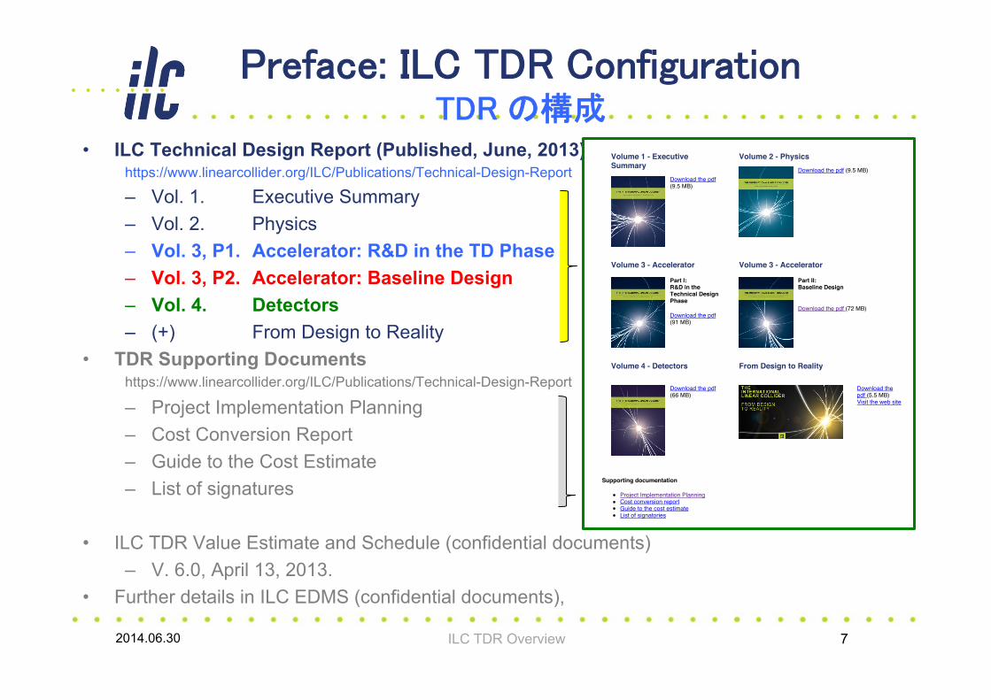
• ILC Technical Design Report (Published, June, 2013) https://www.linearcollider.org/ILC/Publications/Technical-Design-Report
– Vol. 1. Executive Summary – Vol. 2. Physics – Vol. 3, P1. Accelerator: R&D in the TD Phase – Vol. 3, P2. Accelerator: Baseline Design – Vol. 4. Detectors – (+) From Design to Reality
• TDR Supporting Documents https://www.linearcollider.org/ILC/Publications/Technical-Design-Report
– Project Implementation Planning – Cost Conversion Report – Guide to the Cost Estimate – List of signatures
• ILC TDR Value Estimate and Schedule (confidential documents) – V. 6.0, April 13, 2013.
• Further details in ILC EDMS (confidential documents),
2014.06.30 ILC TDR Overview 7
2014/06/25 18:26ILC - Technical Design Report
1/1 ページhttps://www.linearcollider.org/ILC/Publications/Technical-Design-Report
ILC Technical Design ReportPublished on 12 June 2013, The ILC Technical Design Report (TDR) is a five-volume report containing the blueprintfor a future particle physics project. It marks the completion of many years of globally coordinated R&D and completesthe mandate of the Global Design Effort. It contains all the elements needed to propose the ILC to collaboratinggovernments, including a technical design and implementation plan, that are realistic and have been optimised forperformance, cost and risk.
Highlights of the achievements include the successful construction and commissioning of superconductingradiofrequency test facilities for accelerators all over the world, great strides in the improvement of acceleratingcavities production processes, and plans for mass production, as 16,000 superconducting cavities will be needed todrive the ILC’s particle beams. The details of the two state-of-the-art detectors that will record the collisions betweenelectrons and positrons are also part of the report, as well as an extensive outline of the geological and civilengineering studies conducted for siting the ILC.
Read the ILC/LCC press release ( English – Japanese – Chinese – French – German – Spanish) on the reportpublication
Order a printed copy
Volume 1 - ExecutiveSummary
Download the pdf(9.5 MB)
Volume 2 - PhysicsDownload the pdf (9.5 MB)
Volume 3 - Accelerator
Part I:R&D in theTechnical DesignPhase
Download the pdf(91 MB)
Volume 3 - Accelerator
Part II:Baseline Design
Download the pdf (72 MB)
Volume 4 - Detectors
Download the pdf(66 MB)
From Design to Reality
Download thepdf (5.5 MB) Visit the web site
Supporting documentation
Project Implementation PlanningCost conversion reportGuide to the cost estimateList of signatories

ILC-TDR Vol. 3-I Accelerator R&D Vol. 3-I, ILC 加速器技術開発
1. Introduction
2. Superconducting RF (SCRF) technology 1. Cavity field gradient 2. Cavity system test: S1 Global 3. Industrialization E-XFEL 4. … 5. …
3. Beam Test Facilities 1. SCRF, Beam Acceleration: FLASH, STF, 2. Nano-beam handling : ATF 3. E- cloud mitigation: CESR-TA 4. … 5. …
4. Accelerator Systems R&D
5. Conventional Facilities and Siting Studies
6. Post-TDR R&D (to be briefly reported) 1. SCRF, ATF, …
2014.06.30 ILC TDR Overview 8
focused
focused

⁄ FNAL
NML/ASTA facility ILC RF unit test Full-‐CM Test, SRF beam accelera;on, soon
⁄ DESY
TTF/FLASH (DESY) ~1 GeV ILC-‐like beam ILC RF unit STF (KEK) opera;on/construc;on
ILC-‐like Cryomodule test: S1-‐Gloabal SRF beam accelera;on : QB, STF2
⁄ KEK, Japan ⁄
Cornell
CesrTA (Cornell) electron cloud low emi]ance
⁄ INFN Frasca*
DAΦNE (INFN Frasca;) kicker development electron cloud
ATF & ATF2 (KEK) ultra-‐low emi]ance Final Focus op;cs, nano-‐beam KEKB electron-‐cloud
Global Cooperation for Test Facilities �国際協力による加速器試験施設�
9 2014.06.30 ILC TDR Overview
Technical Highlight in TD Phase 技術設計段階での技術開発・ハイライト
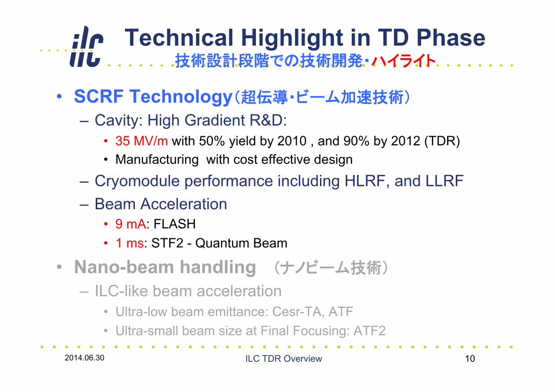
• SCRF Technology(超伝導・ビーム加速技術)
– Cavity: High Gradient R&D: • 35 MV/m with 50% yield by 2010 , and 90% by 2012 (TDR) • Manufacturing with cost effective design
– Cryomodule performance including HLRF, and LLRF – Beam Acceleration
• 9 mA: FLASH • 1 ms: STF2 - Quantum Beam
• Nano-beam handling (ナノビーム技術)
– ILC-like beam acceleration • Ultra-low beam emittance: Cesr-TA, ATF • Ultra-small beam size at Final Focusing: ATF2
2014.06.30 ILC TDR Overview 10

v Ultra-high (Q0 =1010): - small surface resistance à almost zero power (heat) in cavity walls - use relatively low-power microwave source to ‘charge up’ cavity
(高い高周波電力効率) v Long beam pulses (~1 ms) à intra-pulse feedback
(パルス中でのフィードバック制御、可) v Larger aperture / smaller beam loss à better beam quality with larger aperture - lower wake-fields
(大口径à少ビームロス) v Work necessary on engineering for:
- Cryomodule (thermal insultation) - Cryogenics
(冷却) - Gradient to be further improved
L∝ηPRFECM
δBSεy
Luminosity: RF efficiency RF power / beam current
Vertical emittance
(tiny beams)
v Luminosity proportional to RF efficiency ILC v (ルミノシティはRF効率に比例): v for given total power (electricity bill !), v ~160MW @ 500GeV
v Capable of efficiently accelerating high beam currents (大電流)
v Low impedance aids preservation of high beam quality (low emittance)(良質ビーム) à Ideal for Linear Collider
Advantage of Superconducting RF 超伝導RF の特色・利点
2014.06.30 ILC TDR Overview 11
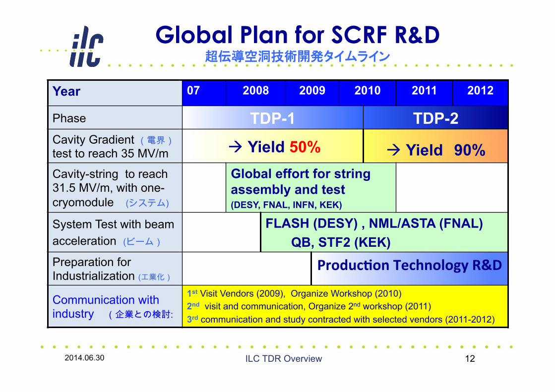
Global Plan for SCRF R&D 超伝導空洞技術開発タイムライン
Year 07 2008 2009 2010 2011 2012
Phase TDP-1 TDP-2 Cavity Gradient (電界)test to reach 35 MV/m à Yield 50% à Yield 90% Cavity-string to reach 31.5 MV/m, with one-cryomodule (システム)
Global effort for string assembly and test (DESY, FNAL, INFN, KEK)
System Test with beam acceleration (ビーム)
FLASH (DESY) , NML/ASTA (FNAL) QB, STF2 (KEK)
Preparation for Industrialization (工業化)
Produc*on Technology R&D
Communication with industry (企業との検討:
1st Visit Vendors (2009), Organize Workshop (2010) 2nd visit and communication, Organize 2nd workshop (2011) 3rd communication and study contracted with selected vendors (2011-2012)
2014.06.30 ILC TDR Overview 12

Progress in 1.3 GHz Cavity Production 1.3 GHz 超伝導加速空洞製造実績の進展
2014.06.30 13
year # 9-cell cavities qualified
Capable Lab. Capable Industry
2006 10 1 DESY
2 ACCEL, ZANON
2011 41 4 DESY, JLAB, FNAL,
KEK
4 RI, ZANON, AES, MHI,
2012 (45) 5 DESY, JLAB, FNAL,
KEK, Cornell
5 RI, ZANON, AES, MHI,
Hitachi
ILC TDR Overview
- One Lab (2 vendor) in 2006, and 5 Lab (5 vendor) in 2012 may handle to fabricate 35 MV/m at Q= 8E9 - 6年間で、技術を保有する研究所、(製造会社)が1,(2) à 5 機関に、.

Progress in SCRF Cavity Gradient 空洞製造・成功率の向上
2014.06.30 14
Production yield: 94 % at > 35+/-20% (目標の> 90 % を達成), Average gradient: 37.1 MV/m reached (2012)
ILC TDR Overview
電界性能幅+/-20 %à成功率(歩留まり)~10% 向上

KEK: SRF Test Facility (STF/STF2) v S1-Global: completed (2010) v Quantum Beam Accelerator (Inverse Laser
Compton): 6.7 mA, 1 ms v CM1 test with beam (2014 ~2015) v STF-COI: Facility to demonstrate CM assembly/test in near future
Cavity string: < 26MV/m>
S1 Global Cryomodule at STF:
DESY: FLASH v 1.25 GeV linac (TESLA-Like tech.) v ILC-like bunch trains: v 600 ms, 9 mA beam (2009); 800 ms 4.5 mA (2012) v RF-cryomodule string with beam à
PXFEL1 operational at FLASH
Max
imum
gra
dien
t [M
V/m
]
45
40
35
30
25
20
15
10
5
01 2 3 4 5 6 7 8
Cavity No.
36.1 MV/m
32.5 MV/m
Vertical testCryomoduleXFEL Prototype at PXFEL1
PXFEL1 : ~ 32MV/m>
FNAL: NML (New Muon Lab) / ASTA (Advanced Superconducting Test Accelerator) v CM1 test complete v CM2 operation (2013) v CM2 with beam (soon)
CM1 at NML Facility:
CM1: ~ 25MV/m>
Cryomodule System Test 超伝導加速空洞・CMおよびビーム加速実証試験
2014.06.30 15
ß ILC ビーム電流の実証
ß ILC ビームパルス長の実証
ILC TDR Overview
Related Documents