penerbit.uthm.edu.my/ojs/index.php/ijie Abstract: This paper presents an experimental study on specimens made with the additive manufacturing (AM) Fused Deposition Material (FDM) technique with PLA material. Several configurations of geometry and printing temperature were made in order to evaluate these parameters over a tensile test. The geometry of the specimen was fabricated according to the ASTM D638 and the curvatures of fillet radius were varied (76-std, 144, 244mm and straight) to obtain optimal fillet radius for tensile test. The nozzle temperature was varied (200, 210, 220 and 230°C) to show its influence on PLA stress-strain behavior. Results have shown that the fillet radius of the specimen and the printer parameters affect material quantity deposited during 3D printing process, leaving to progressive damage areas. Better performance was obtained at 210 °C printing temperature with a fillet radius of 144 mm. A modification geometry specimen were proposed in order to change the increase Z nozzle level point that generates a stress concentrator at the specimen avoiding failure zone at calibrating length of the specimen. Keywords: FDM, PLA, fracture, additive-manufacturing, tensile-test INTERNATIONAL JOURNAL OF INTEGRATED ENGINEERING VOL. 12 NO. 8 (2020) 97-108 © Universiti Tun Hussein Onn Malaysia Publisher’s Office IJIE Journal homepage: http://penerbit.uthm.edu.my/ojs/index.php/ijie ISSN : 2229-838X e-ISSN : 2600-7916 International Journal of Integrated Engineering Relation Between Mechanical Properties and 3D Printer Configurations Parameters Using PLA at Open-Source Prusa I3 J. Sierra 1,2* , D. Sanín 1 , A. Montoya 1 , W. Villaneda 3 1 Department of Mechatronics Engineering, Research Group–MATyER, Instituto Tecnológico Metropolitano, Medellín, COLOMBIA 2 Department of Engineering, Environmental Research Group–GIIAM, Institución Universitaria Pascual Bravo, Medellín, COLOMBIA 3 Department of Mechanical Engineering, Universidad de Antioquia, Medellín, COLOMBIA *Corresponding Author DOI: https://doi.org/10.30880/ijie.2020.12.08.009 Received 30 January 2020; Accepted 4 June 2020; Available online 30 August 2020 1. Introduction Nowadays the additive manufacturing (AM) techniques, commonly known as 3D printing, have grown rapidly with the development and the massif use in design and manufacture, due to the versatility and rapid response and relatively low cost [1]. Some industries like construction, medicine [2] [3] [4] [5] [6], robotics [7], [8], military [9], automotive [10], [11] and others have used this technology with good results. The development of complex geometries in a short time and acceptable results in terms of performance and durability generate expectations about this technology. There are different techniques for obtaining products using additive manufacturing techniques, such: Modeling by molten deposition (FDM), Stereolithography (SLA), Selective Laser Sintering (SLS), Laminated object manufacturing (LOM), Digital light processing (DLP) and Three-dimensional printing (3DP) [12]. Currently, the most popular technique for the manufacture of parts by AM corresponds to the FDM, which was invented and patented in the late 80's by Scott Crump. This technique allows the construction of a CAD model by adding a thermoplastic layer, extruding a filament under conditions previously established by the user. The FDM is made up of three (3) stages: pre- processing, printing and post-processing as shown in Figure 1. In the pre-processing, through free programs like CURA® and Pronterface®, the CAD model is imported, which is usually a .STL (Standard Triangule Lenguage) type file in order to adjust the scale of the model, design the support material (Slicing), and configuration of other *Corresponding author: [email protected] 97 2020 UTHM Publisher. All rights reserved.

Welcome message from author
This document is posted to help you gain knowledge. Please leave a comment to let me know what you think about it! Share it to your friends and learn new things together.
Transcript
penerbit.uthm.edu.my/ojs/index.php/ijie
Abstract: This paper presents an experimental study on specimens made with the additive manufacturing (AM)
Fused Deposition Material (FDM) technique with PLA material. Several configurations of geometry and printing
temperature were made in order to evaluate these parameters over a tensile test. The geometry of the specimen was
fabricated according to the ASTM D638 and the curvatures of fillet radius were varied (76-std, 144, 244mm and
straight) to obtain optimal fillet radius for tensile test. The nozzle temperature was varied (200, 210, 220 and 230°C) to show its influence on PLA stress-strain behavior. Results have shown that the fillet radius of the
specimen and the printer parameters affect material quantity deposited during 3D printing process, leaving to
progressive damage areas. Better performance was obtained at 210 °C printing temperature with a fillet radius of
144 mm. A modification geometry specimen were proposed in order to change the increase Z nozzle level point
that generates a stress concentrator at the specimen avoiding failure zone at calibrating length of the specimen.
Keywords: FDM, PLA, fracture, additive-manufacturing, tensile-test
INTERNATIONAL JOURNAL OF INTEGRATED ENGINEERING VOL. 12 NO. 8 (2020) 97-108
© Universiti Tun Hussein Onn Malaysia Publisher’s Office
IJIE
Journal homepage: http://penerbit.uthm.edu.my/ojs/index.php/ijie
ISSN : 2229-838X e-ISSN : 2600-7916
International
Journal of
Integrated
Engineering
Relation Between Mechanical Properties and 3D Printer
Configurations Parameters Using PLA at Open-Source Prusa I3
J. Sierra1,2*, D. Sanín1, A. Montoya1, W. Villaneda3
1Department of Mechatronics Engineering, Research Group–MATyER,
Instituto Tecnológico Metropolitano, Medellín, COLOMBIA
2Department of Engineering, Environmental Research Group–GIIAM,
Institución Universitaria Pascual Bravo, Medellín, COLOMBIA
3Department of Mechanical Engineering,
Universidad de Antioquia, Medellín, COLOMBIA
*Corresponding Author
DOI: https://doi.org/10.30880/ijie.2020.12.08.009 Received 30 January 2020; Accepted 4 June 2020; Available online 30 August 2020
1. Introduction
Nowadays the additive manufacturing (AM) techniques, commonly known as 3D printing, have grown rapidly with the development and the massif use in design and manufacture, due to the versatility and rapid response and
relatively low cost [1]. Some industries like construction, medicine [2] [3] [4] [5] [6], robotics [7], [8], military [9],
automotive [10], [11] and others have used this technology with good results. The development of complex geometries
in a short time and acceptable results in terms of performance and durability generate expectations about this
technology. There are different techniques for obtaining products using additive manufacturing techniques, such:
Modeling by molten deposition (FDM), Stereolithography (SLA), Selective Laser Sintering (SLS), Laminated object
manufacturing (LOM), Digital light processing (DLP) and Three-dimensional printing (3DP) [12]. Currently, the most popular technique for the manufacture of parts by AM corresponds to the FDM, which was invented and patented in the
late 80's by Scott Crump. This technique allows the construction of a CAD model by adding a thermoplastic layer,
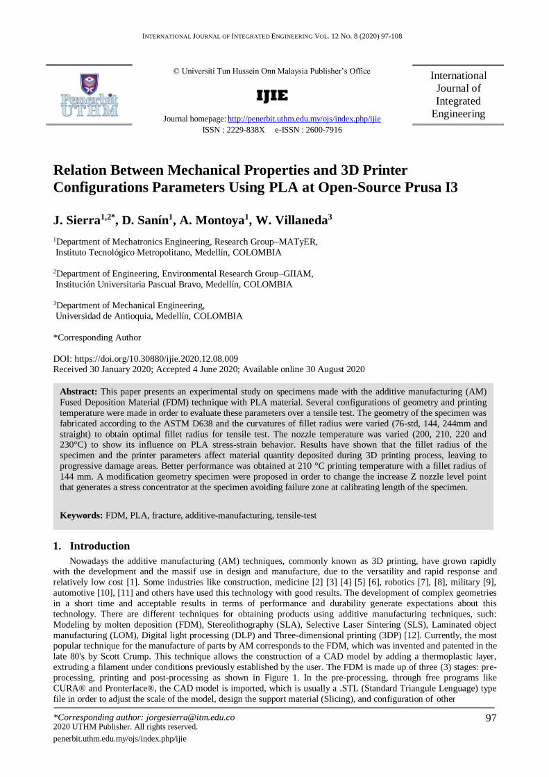
extruding a filament under conditions previously established by the user. The FDM is made up of three (3) stages: pre-
processing, printing and post-processing as shown in Figure 1. In the pre-processing, through free programs like
CURA® and Pronterface®, the CAD model is imported, which is usually a .STL (Standard Triangule Lenguage) type
file in order to adjust the scale of the model, design the support material (Slicing), and configuration of other
*Corresponding author: [email protected] 97 2020 UTHM Publisher. All rights reserved.
98
E. Correa et al., Int. J. of Integrated Engineering Vol. 12 No. 8 (2020) p. 97-108
parameters including the selection of the printing material; there is a large amount of materials that can be used in the
FDM, among which are the PLA (Polylactic Acid) and ABS (Acrylonitrile Butadiene Styrene). Highlighting that the ABS is a relatively low cost and a good balance of mechanical properties [13]. Finally, the simulation and compilation
of the printing process is carried out, establishing the time of the process, amount of material to be used and the
working routine of the 3D printer through the G-Code. In the printing phase, the extruder increases the temperature of
the filament above the softening point (softening temperature) and deposits it at a rate and speed of displacement
previously defined by the user. In the post-processing phase, the support material is removed and the quality of the
surface of the part is checked visually.
Fig. 1 - MA-FDM process
The AM technique by FDM is considered an easy-to-use, freely available and relatively inexpensive. In addition,
using PLA as a working material can be classified as "environmentally friendly". PLA is derived from renewable and
degradable resources such as corn and rice, which can help alleviate the energy crisis as well as reduce the dependence
on fossil fuels of our society. Furthermore, PLA has many advantages like renewability, biocompatibility,
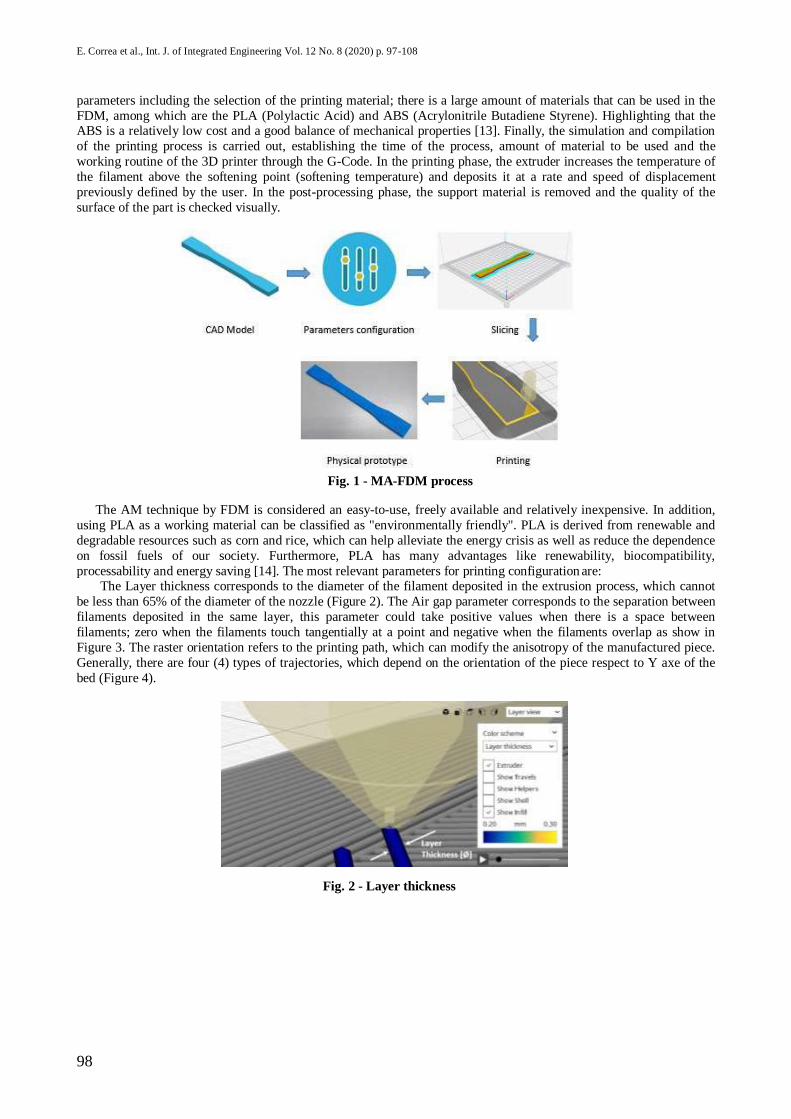
processability and energy saving [14]. The most relevant parameters for printing configuration are: The Layer thickness corresponds to the diameter of the filament deposited in the extrusion process, which cannot
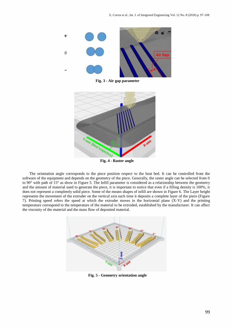
be less than 65% of the diameter of the nozzle (Figure 2). The Air gap parameter corresponds to the separation between
filaments deposited in the same layer, this parameter could take positive values when there is a space between
filaments; zero when the filaments touch tangentially at a point and negative when the filaments overlap as show in
Figure 3. The raster orientation refers to the printing path, which can modify the anisotropy of the manufactured piece.
Generally, there are four (4) types of trajectories, which depend on the orientation of the piece respect to Y axe of the
bed (Figure 4).
Fig. 2 - Layer thickness
99
E. Correa et al., Int. J. of Integrated Engineering Vol. 12 No. 8 (2020) p. 97-108
Fig. 3 - Air gap parameter
Fig. 4 - Raster angle
The orientation angle corresponds to the piece position respect to the heat bed. It can be controlled from the
software of the equipment and depends on the geometry of the piece. Generally, the raster angle can be selected from 0
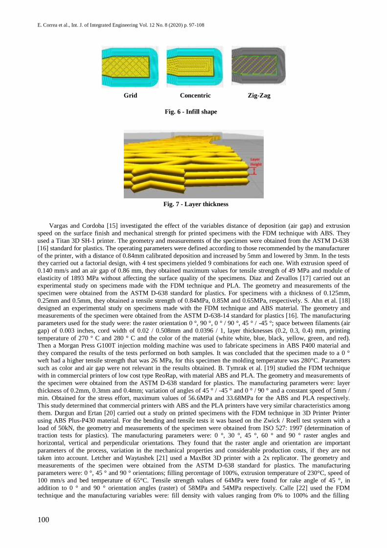
to 90° with path of 15° as show in Figure 5. The Infill parameter is considered as a relationship between the geometry
and the amount of material used to generate the piece, it is important to notice that even if a filling density is 100%, it
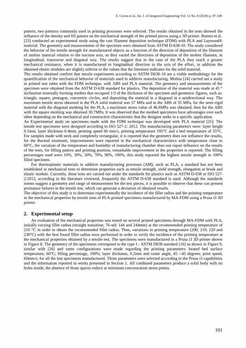
does not represent a completely solid piece. Some of the means shapes of infill are shown in Figure 6. The Layer height
represents the movement of the extruder on the vertical axis each time it deposits a complete layer of the piece (Figure 7). Printing speed refers the speed at which the extruder moves in the horizontal plane (X-Y) and the printing
temperature correspond to the temperature of the material to be extruded, established by the manufacturer. It can affect
the viscosity of the material and the mass flow of deposited material.
Fig. 5 - Geometry orientation angle
100
E. Correa et al., Int. J. of Integrated Engineering Vol. 12 No. 8 (2020) p. 97-108
Grid Concentric Zig-Zag
Fig. 6 - Infill shape
Fig. 7 - Layer thickness
Vargas and Cordoba [15] investigated the effect of the variables distance of deposition (air gap) and extrusion
speed on the surface finish and mechanical strength for printed specimens with the FDM technique with ABS. They
used a Titan 3D SH-1 printer. The geometry and measurements of the specimen were obtained from the ASTM D-638
[16] standard for plastics. The operating parameters were defined according to those recommended by the manufacturer
of the printer, with a distance of 0.84mm calibrated deposition and increased by 5mm and lowered by 3mm. In the tests they carried out a factorial design, with 4 test specimens yielded 9 combinations for each one. With extrusion speed of
0.140 mm/s and an air gap of 0.86 mm, they obtained maximum values for tensile strength of 49 MPa and module of
elasticity of 1893 MPa without affecting the surface quality of the specimens. Diaz and Zevallos [17] carried out an
experimental study on specimens made with the FDM technique and PLA. The geometry and measurements of the
specimen were obtained from the ASTM D-638 standard for plastics. For specimens with a thickness of 0.125mm,
0.25mm and 0.5mm, they obtained a tensile strength of 0.84MPa, 0.85M and 0.65MPa, respectively. S. Ahn et al. [18]
designed an experimental study on specimens made with the FDM technique and ABS material. The geometry and
measurements of the specimen were obtained from the ASTM D-638-14 standard for plastics [16]. The manufacturing
parameters used for the study were: the raster orientation 0 °, 90 °, 0 ° / 90 °, 45 ° / -45 °; space between filaments (air
gap) of 0.003 inches, cord width of 0.02 / 0.508mm and 0.0396 / 1, layer thicknesses (0.2, 0.3, 0.4) mm, printing
temperature of 270 ° C and 280 ° C and the color of the material (white white, blue, black, yellow, green, and red). Then a Morgan Press G100T injection molding machine was used to fabricate specimens in ABS P400 material and
they compared the results of the tests performed on both samples. It was concluded that the specimen made to a 0 °
weft had a higher tensile strength that was 26 MPa, for this specimen the molding temperature was 280°C. Parameters
such as color and air gap were not relevant in the results obtained. B. Tymrak et al. [19] studied the FDM technique
with in commercial printers of low cost type ReoRap, with material ABS and PLA. The geometry and measurements of
the specimen were obtained from the ASTM D-638 standard for plastics. The manufacturing parameters were: layer
thickness of 0.2mm, 0.3mm and 0.4mm; variation of angles of 45 ° / -45 ° and 0 ° / 90 ° and a constant speed of 5mm /
min. Obtained for the stress effort, maximum values of 56.6MPa and 33.68MPa for the ABS and PLA respectively.
This study determined that commercial printers with ABS and the PLA printers have very similar characteristics among
them. Durgun and Ertan [20] carried out a study on printed specimens with the FDM technique in 3D Printer Printer
using ABS Plus-P430 material. For the bending and tensile tests it was based on the Zwick / Roell test system with a
load of 50kN, the geometry and measurements of the specimen were obtained from ISO 527: 1997 (determination of traction tests for plastics). The manufacturing parameters were: 0 °, 30 °, 45 °, 60 ° and 90 ° raster angles and
horizontal, vertical and perpendicular orientations. They found that the raster angle and orientation are important
parameters of the process, variation in the mechanical properties and considerable production costs, if they are not
taken into account. Letcher and Waytashek [21] used a MaxBot 3D printer with a 2x replicator. The geometry and
measurements of the specimen were obtained from the ASTM D-638 standard for plastics. The manufacturing
parameters were: 0 °, 45 ° and 90 ° orientations; filling percentage of 100%, extrusion temperature of 230°C, speed of
100 mm/s and bed temperature of 65°C. Tensile strength values of 64MPa were found for rake angle of 45 °, in
addition to 0 ° and 90 ° orientation angles (raster) of 58MPa and 54MPa respectively. Calle [22] used the FDM
technique and the manufacturing variables were: fill density with values ranging from 0% to 100% and the filling
101
E. Correa et al., Int. J. of Integrated Engineering Vol. 12 No. 8 (2020) p. 97-108
pattern, two patterns commonly used in printing processes were selected. The results obtained in the tests showed the
influence of the density and fill pattern on the mechanical strength of the printed pieces using a 3D printer. Romeo et al.
[23] conducted an experimental study using the cast filament deposition technique (FDM) with PLA and Laywood®
material. The geometry and measurements of the specimen were obtained from ASTM D-638-10. The study considered
the behavior of the tensile strength for manufactured objects as a function of the direction of deposition of the filament
of molten material relative to the traction axis, so they varied the directions of deposition of the molten filament, in
longitudinal, transverse and diagonal way. The results suggest that in the case of the PLA they reach a greater mechanical resistance, when it is manufactured in longitudinal direction to the axis of the effort, in addition the
obtained elastic modules are slightly inferior to the values that the literature indicates for the solid material.
The results obtained confirm that tensile experiments according to ASTM D638-10 are a viable methodology for the
quantification of the mechanical behavior of materials used in additive manufacturing. Molina [24] carried out a study
in printed test tubes with the FDM technique, with ABS and PLA material. The geometry and measurements of the
specimen were obtained from the ASTM D-638 standard for plastics. The deposition of the material was made at 45 °
inclination internally forming meshes that occupied 1/3 of the thickness of the specimen and geometric figures, such as:
triangle, square, pentagon, concentric circles, and depositing the material in a diagonal in a unidirectional way. The
maximum tensile stress obtained in the PLA solid material was 57 MPa and in the ABS of 35 MPa, for the semi-rigid
material with the diagonal meshing for the PLA, a maximum stress value of 46.6MPa was obtained, then for the ABS
with the square meshing was obtained 30.7MPa. It was observed that the meshed specimens have advantages over each other depending on the mechanical and constructive characteristic that the designer seeks in a specific application.
An Experimental study on specimens made with the FDM technique was developed with PLA material [25]. The
tensile test specimens were designed according to ISO 527-2: 2012. The manufacturing parameters were: layer height
0.1mm, layer thickness 0.4mm, printing speed 60 mm/s, printing temperature 195°C and a bed temperature of 55°C.
For samples made with neck and completely rectangular, it is reported that the geometry does not influence the results,
for the thermal treatment, improvements were reported in the mechanical characteristics with temperature close to
60°C, the variation of the temperature and humidity of manufacturing chamber does not report influence on the results
of the tests, for filling pattern and printing position, remarkable improvement in the properties is reported. The filling
percentages used were 10%, 30%, 50%, 70%, 90%, 100%, this study reported the highest tensile strength in 100%
filled specimen.
For thermoplastic materials in additive manufacturing processes (AM), such as PLA, a standard has not been established in mechanical tests to determine properties such as tensile strength, yield strength, elongation at break and
elastic module. Currently, these tests are carried out under the standards for plastics such as ASTM D-638 or ISO 527-
2:2012, according to the literature reviewed, frequently the ASTM D-638 standard is used. Although the standards
norms suggest a geometry and range of measurement for the test pieces, it is possible to observe that these can present
premature failures in the tensile test, which can generate a deviation of obtained results.
The objective of this study is to determine experimentally the incidence of the fillet radius and the printing temperature
in the mechanical properties by tensile tests of PLA-printed specimens manufactured by MA-FDM using a Prusa i3 3D
printer.
2. Experimental setup
An evaluation of the mechanical properties was tested on several printed specimens through MA-FDM with PLA, initially varying fillet radius (straight transition; 76-std; 144 and 244mm) at the recommended printing temperature of
210 °C in order to obtain the recommended fillet radius. Then, variations in printing temperature (200; 210; 220 and
230°C) with the best found fillet radius were performed in order to verify the incidence of the printing temperature at
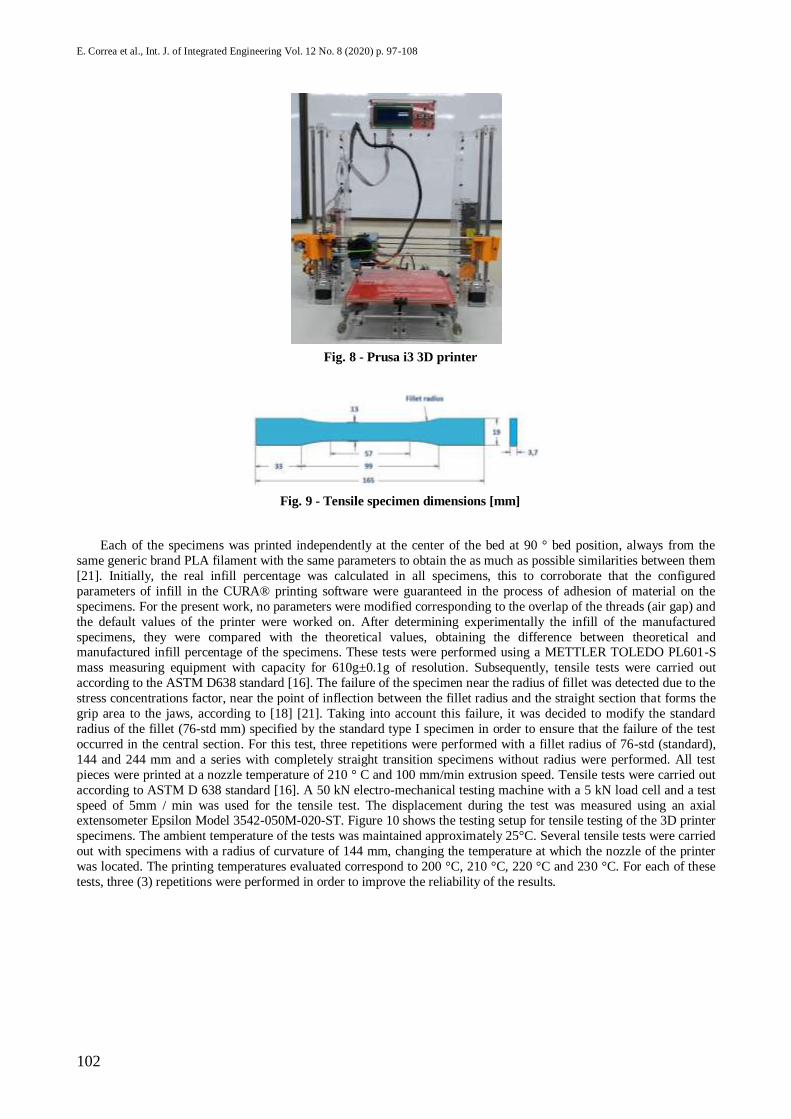
the mechanical properties obtained by a tensile test. The specimens were manufactured in a Prusa i3 3D printer shown
in Figure 8. The geometry of the specimens correspond to the type I - ASTM D638 standard [16] as shown in Figure 9,
similar with [26] and some configurations were made regarding the printing parameters: heated bed surface
temperature, 60°C; filling percentage, 100%; layer thickness, 0.2mm and raster angle, 45 /-45 degrees; print speed,
60mm/s; for all the test specimens manufactured. Those parameters were selected according to the Prusa i3 capabilities
and the information reported in works presented in Section 1. All combined parameters produce a solid body with no
holes inside, the absence of those spaces reduce at minimum concentration stress points.
102
E. Correa et al., Int. J. of Integrated Engineering Vol. 12 No. 8 (2020) p. 97-108
Fig. 8 - Prusa i3 3D printer
Fig. 9 - Tensile specimen dimensions [mm]
Each of the specimens was printed independently at the center of the bed at 90 ° bed position, always from the
same generic brand PLA filament with the same parameters to obtain the as much as possible similarities between them
[21]. Initially, the real infill percentage was calculated in all specimens, this to corroborate that the configured
parameters of infill in the CURA® printing software were guaranteed in the process of adhesion of material on the
specimens. For the present work, no parameters were modified corresponding to the overlap of the threads (air gap) and
the default values of the printer were worked on. After determining experimentally the infill of the manufactured
specimens, they were compared with the theoretical values, obtaining the difference between theoretical and manufactured infill percentage of the specimens. These tests were performed using a METTLER TOLEDO PL601-S
mass measuring equipment with capacity for 610g±0.1g of resolution. Subsequently, tensile tests were carried out
according to the ASTM D638 standard [16]. The failure of the specimen near the radius of fillet was detected due to the
stress concentrations factor, near the point of inflection between the fillet radius and the straight section that forms the
grip area to the jaws, according to [18] [21]. Taking into account this failure, it was decided to modify the standard
radius of the fillet (76-std mm) specified by the standard type I specimen in order to ensure that the failure of the test
occurred in the central section. For this test, three repetitions were performed with a fillet radius of 76-std (standard),
144 and 244 mm and a series with completely straight transition specimens without radius were performed. All test
pieces were printed at a nozzle temperature of 210 ° C and 100 mm/min extrusion speed. Tensile tests were carried out
according to ASTM D 638 standard [16]. A 50 kN electro-mechanical testing machine with a 5 kN load cell and a test
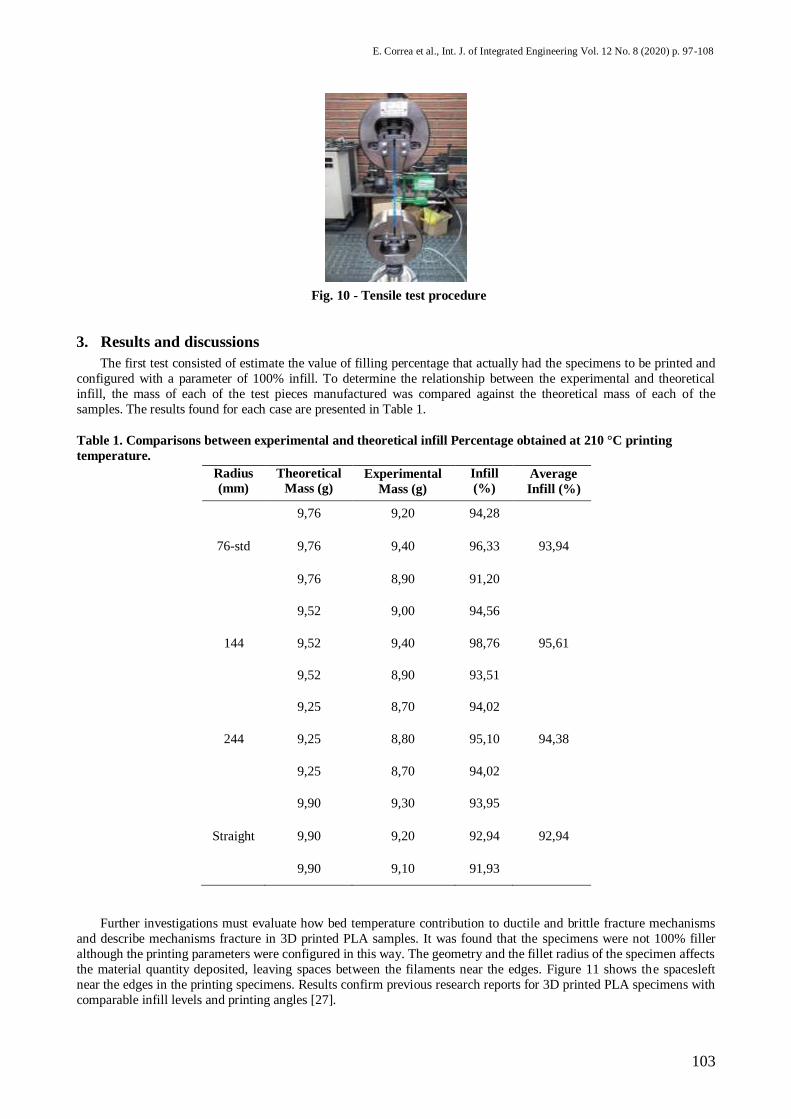
speed of 5mm / min was used for the tensile test. The displacement during the test was measured using an axial extensometer Epsilon Model 3542-050M-020-ST. Figure 10 shows the testing setup for tensile testing of the 3D printer
specimens. The ambient temperature of the tests was maintained approximately 25°C. Several tensile tests were carried
out with specimens with a radius of curvature of 144 mm, changing the temperature at which the nozzle of the printer
was located. The printing temperatures evaluated correspond to 200 °C, 210 °C, 220 °C and 230 °C. For each of these
tests, three (3) repetitions were performed in order to improve the reliability of the results.
103
E. Correa et al., Int. J. of Integrated Engineering Vol. 12 No. 8 (2020) p. 97-108
Fig. 10 - Tensile test procedure
3. Results and discussions
The first test consisted of estimate the value of filling percentage that actually had the specimens to be printed and
configured with a parameter of 100% infill. To determine the relationship between the experimental and theoretical
infill, the mass of each of the test pieces manufactured was compared against the theoretical mass of each of the
samples. The results found for each case are presented in Table 1.
Table 1. Comparisons between experimental and theoretical infill Percentage obtained at 210 °C printing
temperature.
Radius
(mm)
Theoretical
Mass (g) Experimental
Mass (g)
Infill
(%) Average
Infill (%)
9,76 9,20 94,28
76-std 9,76 9,40 96,33 93,94
9,76 8,90 91,20
9,52 9,00 94,56
144 9,52 9,40 98,76 95,61
9,52 8,90 93,51
9,25 8,70 94,02
244 9,25 8,80 95,10 94,38
9,25 8,70 94,02
9,90 9,30 93,95
Straight 9,90 9,20 92,94 92,94
9,90 9,10 91,93
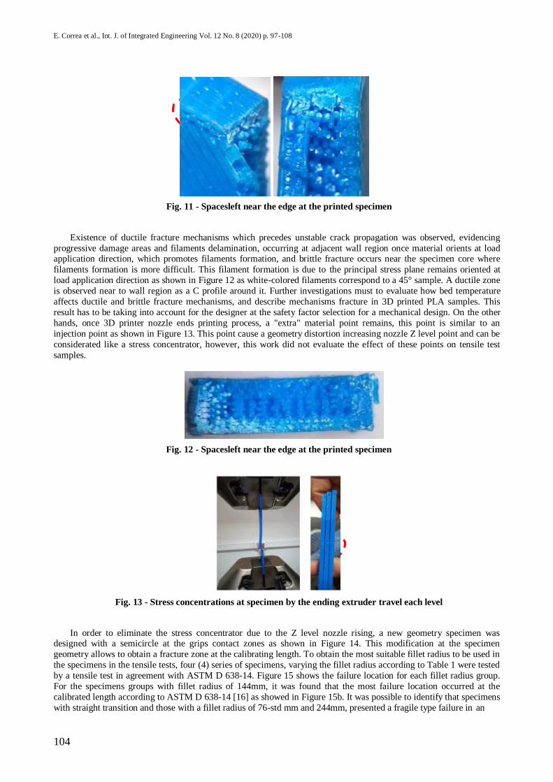
Further investigations must evaluate how bed temperature contribution to ductile and brittle fracture mechanisms
and describe mechanisms fracture in 3D printed PLA samples. It was found that the specimens were not 100% filler
although the printing parameters were configured in this way. The geometry and the fillet radius of the specimen affects
the material quantity deposited, leaving spaces between the filaments near the edges. Figure 11 shows the spacesleft
near the edges in the printing specimens. Results confirm previous research reports for 3D printed PLA specimens with
comparable infill levels and printing angles [27].
104
E. Correa et al., Int. J. of Integrated Engineering Vol. 12 No. 8 (2020) p. 97-108
Fig. 11 - Spacesleft near the edge at the printed specimen
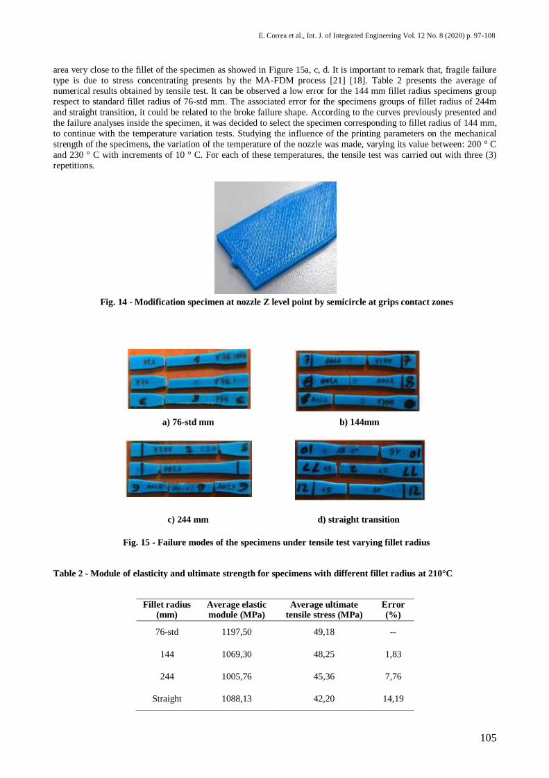
Existence of ductile fracture mechanisms which precedes unstable crack propagation was observed, evidencing
progressive damage areas and filaments delamination, occurring at adjacent wall region once material orients at load application direction, which promotes filaments formation, and brittle fracture occurs near the specimen core where
filaments formation is more difficult. This filament formation is due to the principal stress plane remains oriented at
load application direction as shown in Figure 12 as white-colored filaments correspond to a 45° sample. A ductile zone
is observed near to wall region as a C profile around it. Further investigations must to evaluate how bed temperature
affects ductile and brittle fracture mechanisms, and describe mechanisms fracture in 3D printed PLA samples. This
result has to be taking into account for the designer at the safety factor selection for a mechanical design. On the other
hands, once 3D printer nozzle ends printing process, a "extra" material point remains, this point is similar to an
injection point as shown in Figure 13. This point cause a geometry distortion increasing nozzle Z level point and can be
considerated like a stress concentrator, however, this work did not evaluate the effect of these points on tensile test
samples.
Fig. 12 - Spacesleft near the edge at the printed specimen
Fig. 13 - Stress concentrations at specimen by the ending extruder travel each level
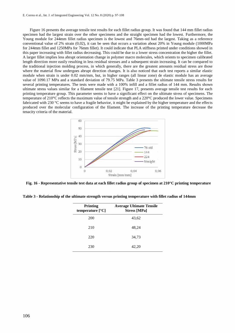
In order to eliminate the stress concentrator due to the Z level nozzle rising, a new geometry specimen was designed with a semicircle at the grips contact zones as shown in Figure 14. This modification at the specimen
geometry allows to obtain a fracture zone at the calibrating length. To obtain the most suitable fillet radius to be used in
the specimens in the tensile tests, four (4) series of specimens, varying the fillet radius according to Table 1 were tested
by a tensile test in agreement with ASTM D 638-14. Figure 15 shows the failure location for each fillet radius group.
For the specimens groups with fillet radius of 144mm, it was found that the most failure location occurred at the
calibrated length according to ASTM D 638-14 [16] as showed in Figure 15b. It was possible to identify that specimens
with straight transition and those with a fillet radius of 76-std mm and 244mm, presented a fragile type failure in an
105
E. Correa et al., Int. J. of Integrated Engineering Vol. 12 No. 8 (2020) p. 97-108
area very close to the fillet of the specimen as showed in Figure 15a, c, d. It is important to remark that, fragile failure
type is due to stress concentrating presents by the MA-FDM process [21] [18]. Table 2 presents the average of numerical results obtained by tensile test. It can be observed a low error for the 144 mm fillet radius specimens group
respect to standard fillet radius of 76-std mm. The associated error for the specimens groups of fillet radius of 244m
and straight transition, it could be related to the broke failure shape. According to the curves previously presented and
the failure analyses inside the specimen, it was decided to select the specimen corresponding to fillet radius of 144 mm,
to continue with the temperature variation tests. Studying the influence of the printing parameters on the mechanical
strength of the specimens, the variation of the temperature of the nozzle was made, varying its value between: 200 ° C
and 230 ° C with increments of 10 ° C. For each of these temperatures, the tensile test was carried out with three (3)
repetitions.
Fig. 14 - Modification specimen at nozzle Z level point by semicircle at grips contact zones
a) 76-std mm b) 144mm
c) 244 mm d) straight transition
Fig. 15 - Failure modes of the specimens under tensile test varying fillet radius
Table 2 - Module of elasticity and ultimate strength for specimens with different fillet radius at 210°C
Fillet radius (mm)
Average elastic module (MPa)
Average ultimate tensile stress (MPa)
Error (%)
76-std 1197,50 49,18 --
144 1069,30 48,25 1,83
244 1005,76 45,36 7,76
Straight 1088,13 42,20 14,19
106
E. Correa et al., Int. J. of Integrated Engineering Vol. 12 No. 8 (2020) p. 97-108
Figure 16 presents the average tensile test results for each fillet radius group. It was found that 144 mm fillet radius
specimen had the largest strain over the other specimens and the straight specimen had the lowest. Furthermore, the Young module for 244mm fillet radius specimen is the lowest and 76mm-std had the largest. Taking as a reference
conventional value of 2% strain (0,02), it can be seen that occurs a variation about 20% in Young module (1000MPa
for 244mm fillet and 1250MPa for 76mm fillet). It could indicate that PLA stiffness printed under conditions showed in
this paper increasing with fillet radius decreasing. This could be due to a lower stress concentration the higher the fillet.
A larger fillet implies less abrupt orientation change in polymer macro molecules, which orients to specimen calibrated
length direction more easily resulting in less residual stresses and a subsequent strain increasing. It can be compared to
the traditional injection molding process, in which generally, there are the greatest amounts residual stress are those
where the material flow undergoes abrupt direction changes. It is also noticed that each test reports a similar elastic
module when strain is under 0.02 mm/mm, but, in higher ranges (all linear zone) de elastic module has an average
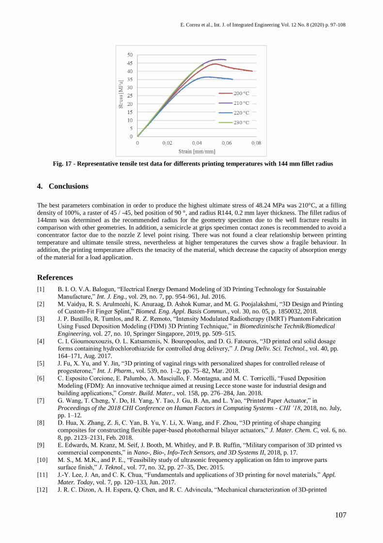
value of 1090.17 MPa and a standard deviation of 79.75 MPa. Table 3 presents the ultimate tensile stress results for
several printing temperatures. The tests were made with a 100% infill and a fillet radius of 144 mm. Results shown ultimate stress values similar for a filament tensile test [21]. Figure 17, presents average tensile test results for each
printing temperature group. This parameter seems to have a significant effect on the ultimate stress of specimens. The
temperature of 210°C reflects the maximum value of tensile strength and a 220°C produced the lower value. Specimens
fabricated with 230 °C seems to have a fragile behavior, it might be explained by the higher temperature and the effects
produced over the molecular configuration of the filament. The increase of the printing temperature decrease the
tenacity criteria of the material.
Fig. 16 - Representative tensile test data at each fillet radius group of specimen at 210°C printing temperature
Table 3 - Relationship of the ultimate strength versus printing temperature with fillet radius of 144mm
Printing
temperature [°C]
Average Ultimate Tensile
Stress [MPa]
200 43,62
210 48,24
220 34,73
230 42,20
107
E. Correa et al., Int. J. of Integrated Engineering Vol. 12 No. 8 (2020) p. 97-108
Fig. 17 - Representative tensile test data for differents printing temperatures with 144 mm fillet radius
4. Conclusions
The best parameters combination in order to produce the highest ultimate stress of 48.24 MPa was 210°C, at a filling
density of 100%, a raster of 45 / -45, bed position of 90 °, and radius R144, 0.2 mm layer thickness. The fillet radius of 144mm was determined as the recommended radius for the geometry specimen due to the well fracture results in
comparison with other geometries. In addition, a semicircle at grips specimen contact zones is recommended to avoid a
concentrator factor due to the nozzle Z level point rising. There was not found a clear relationship between printing
temperature and ultimate tensile stress, nevertheless at higher temperatures the curves show a fragile behaviour. In
addition, the printing temperature affects the tenacity of the material, which decrease the capacity of absorption energy
of the material for a load application.
References
[1] B. I. O. V.A. Balogun, “Electrical Energy Demand Modeling of 3D Printing Technology for Sustainable
Manufacture,” Int. J. Eng., vol. 29, no. 7, pp. 954–961, Jul. 2016.
[2] M. Vaidya, R. S. Arulmozhi, K. Anuraag, D. Ashok Kumar, and M. G. Poojalakshmi, “3D Design and Printing of Custom-Fit Finger Splint,” Biomed. Eng. Appl. Basis Commun., vol. 30, no. 05, p. 1850032, 2018.
[3] J. P. Bustillo, R. Tumlos, and R. Z. Remoto, “Intensity Modulated Radiotherapy (IMRT) Phantom Fabrication
Using Fused Deposition Modeling (FDM) 3D Printing Technique,” in Biomedizinische Technik/Biomedical
Engineering, vol. 27, no. 10, Springer Singapore, 2019, pp. 509–515.
[4] C. I. Gioumouxouzis, O. L. Katsamenis, N. Bouropoulos, and D. G. Fatouros, “3D printed oral solid dosage forms containing hydrochlorothiazide for controlled drug delivery,” J. Drug Deliv. Sci. Technol., vol. 40, pp.
164–171, Aug. 2017.
[5] J. Fu, X. Yu, and Y. Jin, “3D printing of vaginal rings with personalized shapes for controlled release of
progesterone,” Int. J. Pharm., vol. 539, no. 1–2, pp. 75–82, Mar. 2018.
[6] C. Esposito Corcione, E. Palumbo, A. Masciullo, F. Montagna, and M. C. Torricelli, “Fused Deposition
Modeling (FDM): An innovative technique aimed at reusing Lecce stone waste for industrial design and
building applications,” Constr. Build. Mater., vol. 158, pp. 276–284, Jan. 2018.
[7] G. Wang, T. Cheng, Y. Do, H. Yang, Y. Tao, J. Gu, B. An, and L. Yao, “Printed Paper Actuator,” in
Proceedings of the 2018 CHI Conference on Human Factors in Computing Systems - CHI ’18, 2018, no. July, pp. 1–12.
[8] D. Hua, X. Zhang, Z. Ji, C. Yan, B. Yu, Y. Li, X. Wang, and F. Zhou, “3D printing of shape changing
composites for constructing flexible paper-based photothermal bilayer actuators,” J. Mater. Chem. C, vol. 6, no.
8, pp. 2123–2131, Feb. 2018.
[9] E. Edwards, M. Kranz, M. Seif, J. Booth, M. Whitley, and P. B. Ruffin, “Military comparison of 3D printed vs
commercial components,” in Nano-, Bio-, Info-Tech Sensors, and 3D Systems II, 2018, p. 17.
[10] M. S., M. M.K., and P. E., “Feasibility study of ultrasonic frequency application on fdm to improve parts
surface finish,” J. Teknol., vol. 77, no. 32, pp. 27–35, Dec. 2015.
[11] J.-Y. Lee, J. An, and C. K. Chua, “Fundamentals and applications of 3D printing for novel materials,” Appl.
Mater. Today, vol. 7, pp. 120–133, Jun. 2017.
[12] J. R. C. Dizon, A. H. Espera, Q. Chen, and R. C. Advincula, “Mechanical characterization of 3D-printed
108
E. Correa et al., Int. J. of Integrated Engineering Vol. 12 No. 8 (2020) p. 97-108
polymers,” Addit. Manuf., vol. 20, pp. 44–67, 2018.
[13] A. R. Moghadassi, E. Bagheripour, F. Parvizian, and S. M. Hosseini, “Fabrication of (Acrylonitrile Butadiene Styrene/Poly Ethylene Glycol) Nanofiltration Membrane: the Effect of PEG Concentration and Operating
Conditions on Membrane Performance,” Int. J. Eng., vol. 31, no. 10, pp. 1609–1616, Oct. 2018. [14] L. Xiao, B. Wang, G. Yang, and M. Gauthier, “Poly(Lactic Acid)-Based Biomaterials: Synthesis, Modification
and Applications,” Biomed. Sci. Eng. Technol., no. January, 2012.
[15] E. Vargas, L. Cordoba, “Calidad superficial en el prototipado rápido , proceso FDM,” Rev. Ing. E Investig., no.
56, pp. 28–32, 2004.
[16] ASTM Standard D638-14, “Standard test methods for tensile properties of plastics.” ASTM International, West Conshohocken, PA, 2010.
[17] S. J. Diaz Hipolito and P. D. Zevallos Paredes, “Evaluación de la resistencia a la tracción y la cristalinidad del
acido poliláctico (PLA) procesado mediante impresión 3D tipo FDM,” 2016.
[18] S. Ahn, M. Montero, D. Odell, S. Roundy, and P. K. Wright, “Anisotropic material properties of fused
deposition modeling ABS,” Rapid Prototyp. J., vol. 8, no. 4, pp. 248–257, Oct. 2002.
[19] B. M. Tymrak, M. Kreiger, and J. M. Pearce, “Mechanical properties of components fabricated with open-
source 3-D printers under realistic environmental conditions,” Mater. Des., vol. 58, pp. 242–246, Jun. 2014.
[20] I. Durgun and R. Ertan, “Experimental investigation of FDM process for improvement of mechanical properties
and production cost,” Rapid Prototyp. J., vol. 20, no. 3, pp. 228–235, 2014. [21] T. Letcher and M. Waytashek, “Material Property Testing of 3D-Printed Specimen in PLA on an Entry-Level
3D Printer,” in Volume 2A: Advanced Manufacturing, 2014, pp. 1–8.
[22] W. Calle Guamantario, “Influencia de los parametros de relleno en el comportamiento mecanico a la flexion de piezas fabricadas en impresoras 3D de bajo coste,” Universitat Politecnica de Valencia, 2014.
[23] R. Munoz, A. Hernandez, F. Roshardt, J. R. Vega Baudrit, and R. Christoph, “IMPRESION 3D: PRUEBAS
DE RESISTENCIA DE MATERIALES DE ACUERDO A NORMA ASTM D638-10,” Inst. Ciencias, Tecnol.
e Innovación, no. June, 2015.
[24] J. V. Molina Osejos, “Caracterización de termoplásticos de ABS y PLA semi-rigido impresos en 3D con cinco
mallados internos diferentes,” Escuela Politécnica Nacional, 2016.
[25] A. Javier Del Medico Bravo Tutora and M. Milagros Laz Pavón, “Propiedades Mecánicas De Componentes
Fabricados Mediante Modelado Por Deposición Fundida,” 2017.
[26] S. Rahimi, Z. Baniamerian, S. Mazdak, and E. S. Tashnizi, “A 3D Numerical and Empirical Study on the
Effects of Injection Pressure and Temperature on the Quality of Produced Mold,” Int. J. Eng., vol. 31, no. 3, pp.
487–494, Mar. 2018. [27] Y. Song, Y. Li, W. Song, K. Yee, K.-Y. Lee, and V. L. Tagarielli, “Measurements of the mechanical response
of unidirectional 3D-printed PLA,” Mater. Des., vol. 123, pp. 154–164, Jun. 2017.
Related Documents