September 1, 2007 Lit. No. 50579, Rev. 01 A SUBSIDIARY OF DOUGLAS DYNAMICS, L.L.C. CAUTION Read this document before installing the snowplow. CAUTION See your FISHER ® outlet/Web site for specific vehicle application recommendations before installation. The Kit Selection Guide has specific vehicle and snowplow requirements. Fisher Engineering P.O. Box 529 Rockland, Maine 04841 • www.fisherplows.com XLS™ SNOWPLOW Installation Instructions 50600 50810

Welcome message from author
This document is posted to help you gain knowledge. Please leave a comment to let me know what you think about it! Share it to your friends and learn new things together.
Transcript

September 1, 2007Lit. No. 50579, Rev. 01
A SUBSIDIARY OF DOUGLAS DYNAMICS, L.L.C.
CAUTIONRead this document before installing thesnowplow.
CAUTIONSee your FISHER® outlet/Web site for specificvehicle application recommendations beforeinstallation. The Kit Selection Guide hasspecific vehicle and snowplow requirements.
Fisher EngineeringP.O. Box 529 Rockland, Maine 04841 • www.fisherplows.com
XLS™ SNOWPLOWInstallation Instructions
5060050810

Lit. No. 50579, Rev. 01 2 September 1, 2007
50600, 50810
SAFETY DEFINITIONS
Instruction Label
Warning/Caution Label
CAUTIONIndicates a potentially hazardous situationthat, if not avoided, may result in minor ormoderate injury. It may also be used to alertagainst unsafe practices.
NOTE: Indicates a situation or action that can leadto damage to your snowplow and vehicle or otherproperty. Other useful information can also bedescribed.
WARNING/CAUTION AND INSTRUCTIONLABELS
Become familiar with and inform users aboutthe warning labels on the back of the blade and theinstruction label on the headgear.
NOTE: If labels are missing or cannot be read, seeyour sales outlet.
Attachment Arm
Jack Lock
Headgear
Jack (fully raised)
HeadlampBracket
Jack (lowered)
Pin Release Handle (lowered)
JackHandle
Connecting Pin
Pushplate
Jack
Stop
Pin Release Handle (raised)
PUSH
AT
TA
CH
DE
TA
CH
27451
U.S Patents 4,999,935; 5,353,530; 5,420,480; 6,253,470; 6,944,978; RE 35,700; CAN Patent 2,060,425; and other patents pending.
Read Owner's Manual For Complete Instructions
1. Push Pin Release Handle down to pull out Connecting Pins.
2. Drive vehicle slowly to engage Pushplates into Attachment Arms.
3. Stand in front of blade. Fully raise Pin Release Handle to release Connecting Pins.
4. Push Headgear toward vehicle to allow Connecting Pins to fully engage Pushplates. If unable to push Headgear from in front of blade, stand in front of Headgear on driver side and push Headlamp Bracket.
5. Pull out Jack Lock. Push Pin Release Handle into Stop.6. While holding Jack Lock out, use Jack Handle to raise
Jack fully. Release Jack Lock.7. Attach all electrical connectors.
1. Place control in Lower/Float to put blade down.
2. Pull and hold Jack Lock out. Jack will drop to ground. Then pull Pin Release Handle away from Stop and Jack Lock. Release Jack Lock. Verify Jack is locked by trying to lift Jack.
3. Stand in front of blade. While pushing Headgear toward vehicle with left hand, push Pin Release Handle down to disengage Connecting Pins. Make sure Connecting Pins are fully retracted. If unable to push Headgear from in front of blade, stand in front of Headgear on driver side and push Headlamp Bracket.
4. Detach all electrical connectors.
Multiple Pinch Points Label
WARNINGIndicates a potentially hazardous situationthat, if not avoided, could result in death orserious personal injury.
MultiplePinch Points
2959329593
WARNING
XLS™ Blades Only (both sides)

Lit. No. 50579, Rev. 01 3 September 1, 2007
50600, 50810
HYDRAULIC SAFETY
• Always inspect hydraulic components and hosesbefore using. Replace any damaged or worn partsimmediately.
• If you suspect a hose leak, DO NOT use yourhand to locate it. Use a piece of cardboard orwood.
FUSES
The FISHER® electrical and hydraulic systems containseveral blade-style automotive fuses. If a problemshould occur and fuse replacement is necessary, thereplacement fuse must be of the same type andamperage rating as the original. Installing a fuse with ahigher rating can damage the system and could start afire. Fuse Replacement, including fuse ratings andlocations, is located in the Maintenance Section of theOwner's Manual.
WARNINGHydraulic fluid under pressure can cause skininjection injury. If you are injured by hydraulicfluid, get medical attention immediately.
SAFETY PRECAUTIONSImproper installation and operation could causepersonal injury, and/or equipment and propertydamage. Read and understand labels and the Owner'sManual before installing, operating, or makingadjustments.
WARNINGLower blade when vehicle is parked.Temperature changes could change hydraulicpressure, causing the blade to dropunexpectedly or damaging hydrauliccomponents. Failure to do this can result inserious personal injury.
WARNINGRemove blade assembly before placing vehicleon hoist.
WARNINGThe driver shall keep bystanders clear of theblade when it is being raised, lowered or angled.Do not stand between the vehicle and the bladeor within 8 feet of a moving blade. A moving orfalling blade could cause personal injury.
WARNINGDo not exceed GVWR or GAWR includingblade and ballast. The rating label is found ondriver-side vehicle door cornerpost.
WARNINGTo prevent accidental movement of the blade,always turn the ON/OFF switch to OFFwhenever the snowplow is not in use. Thecontrol indicator light will turn off.
WARNINGKeep hands and feet clear of the blade andA-frame when mounting or removing thesnowplow. Moving or falling assemblies couldcause personal injury.
CAUTIONRefer to the current Kit Selection Guide forminimum vehicle recommendations andballast requirements.
CAUTIONAssembling a hose to the incorrect wing ramport can result in permanent damage to theram.

Lit. No. 50579, Rev. 01 4 September 1, 2007
50600, 50810
BATTERY SAFETY
TORQUE CHART
Recommended Fastener Torque Chart (Ft.-Lb.)
SizeSAE
Grade 2SAE
Grade 5SAE
Grade 8
1/4-205/16-183/8-163/8-247/16-141/2-139/16-125/8-11 3/4-10 7/8-9 1-8
611192430456693150150220
91831465075110150250378583
1328 46 68 75 115 165 225 370 591 893
Metric Grade 8.8 (Ft.-Lb.)
Size TorqueSizeTorque
M 6M 8M 10
M 12M 14M 16
717 35
60 95 155
These torque values apply to fastenersexcept those noted in the instruction.
CAUTIONBatteries normally produce explosive gaseswhich can cause personal injury. Therefore, donot allow flames, sparks or lit tobacco to comenear the battery. When charging or workingnear a battery, always cover your face andprotect your eyes, and also provide ventilation.Batteries contain sulfuric acid which burnsskin, eyes and clothing.Disconnect the battery before removing orreplacing any electrical components.
CAUTIONRead instructions before assembling.Fasteners should be finger tight untilinstructed to tighten according to torque chart.Use standard methods and practices whenattaching snowplow including proper personalprotective safety equipment.
WARNINGVehicle exhaust contains lethal fumes.Breathing these fumes, even in lowconcentrations, can cause death. Neveroperate a vehicle in an enclosed area withoutventing exhaust to the outside.
PERSONAL SAFETY
• Remove ignition key and put the vehicle in park orin gear to prevent others from starting the vehicleduring installation or service.
• Wear only snug-fitting clothing while working onyour vehicle or snowplow.
• Do not wear jewelry or a necktie, and secure longhair.
• Wear safety goggles to protect your eyes frombattery acid, gasoline, dirt and dust.
• Avoid touching hot surfaces such as the engine,radiator, hoses and exhaust pipes.
• Always have a fire extinguisher rated BC handy,for flammable liquids and electrical fires.
FIRE AND EXPLOSION
Be careful when using gasoline. Do not use gasolineto clean parts. Store only in approved containers awayfrom sources of heat or flame.
VENTILATION
WARNINGGasoline is highly flammable and gasolinevapor is explosive. Never smoke while workingon vehicle. Keep all open flames away fromgasoline tank and lines. Wipe up any spilledgasoline immediately.

Lit. No. 50579, Rev. 01 5 September 1, 2007
50600, 50810
BLADE, A-FRAME AND HEADGEAR
1. Remove the headlamp box and small parts boxfrom the carton. Remove the carton wall sleeve bysliding it up and over the box contents. Removeand discard the four corner tubes and place thesleeve flat on the floor. Remove the headgear andpower unit assembly from the box and place it onthe carton sleeve. Remove the A-frame and placeit on the carton sleeve.
2. Place some cardboard or wood on the floor wherethe blade will be assembled. Remove the bladefrom the pallet and place it face down. Position theA-frame assembly so that the holes in the A-frameare aligned with the holes in the blade. Insert thepivot bolt (from top to bottom) through all holes.Secure with a 1" locknut and tighten.
3. Cut the tie holding the angle rams to the A-frame.Remove the protective caps on the angle rams.Swing the A-frame to one side so that the holes inthe rod end of the angle ram and the blade arealigned.
4. Install a 1" x 4-3/4" clevis pin from the top down.Swing the A-frame to the other side and securethe second angle ram in the same manner. Securethe angle rams by installing 1/4" x 1-1/2" cotterpins in the two rod-end clevis pins.
5. Remove the 1" x 4" clevis pin from the base end ofone of the angle rams and install the fitting asshown.
Reattach the base end of the angle ram with a1" x 4" clevis pin and secure with a 1-1/2" cotterpin. Repeat this process for the second angle ram.
Pivot Bolt
Locknut
Clevis Pin
Cotter Pin
20°
PS Angle Ram
90°Elbow
20°
DS Angle Ram
90°Elbow

Lit. No. 50579, Rev. 01 6 September 1, 2007
50600, 50810
Nut
Lock Washer
U-Bolt
Mounting Tab
Extension Spring
Nut
6. Stand the blade and A-frame upright and supportin a level position using block under the mainA-frame tube. Install the blade guides.
8. Place a U-bolt on the extension spring. Attach a3/8" nut on each side of the U-bolt. Insert theU-bolt through the mounting tab on the A-frame.Place lock washers and 3/8" nuts on the U-boltand tighten.
9. Remove the support block from under the A-frameand lower the A-frame to the ground, again placingit on the carton sleeve.
7. Install a 3/8" U-bolt through a link in one end of thelift chain. Attach U-bolt and chain to the holes onthe driver-side A-frame brace with 3/8" lockwashers and nuts. Tighten.
Nuts
U-BoltLift Chain
Lock Washers
Extension SpringU-Bolt
Nuts
Nuts
Lock Washers
Lit. No. 50579, Rev. 01 7 September 1, 2007
50600, 50810
Measure this distance
Center of Connecting Pin Hole
Push Plate Height (hole center to ground)
Rear Hole
17" to 19" Top 15" to 17" (typical) Middle
13" to 15" Bottom
10. With the vehicle parked on a solid level surface,measure the distance from the center of theconnecting pin hole to the ground. Using thismeasurement refer to the hole selection chart anddetermine which hole should be used to attach theheadgear to the A-frame.
11. Lower the jack leg in the headgear assembly so thatsix complete slots are showing through the top of theheadgear cross bar. Release the jack lock to holdthe jack in place. Place the headgear assembly ontop of the A-frame assembly so the headgear istipped backward and the jack leg is in between the
Step Pin
Cotter Pin
6 Slots
Jack Handle Nut
Jack Lock
Jack
3/8" Lock Washer
A-frame and push assembly. Attach the jack handleto the jack with a 3/8" lock washer and nut.
12. Position the headgear so that the holes in theheadgear are aligned with the previously selectedholes in the push assembly. Attach the A-frame tothe headgear assembly with two step pins and1/4" x 1-1/2" cotter pins. Insert the step pins fromthe outside of the headgear.
13. If the lowest set of holes in the push assembly areused, the stacking stops attached to the lift framecan be removed.
Lit. No. 50579, Rev. 01 8 September 1, 2007
50600, 50810
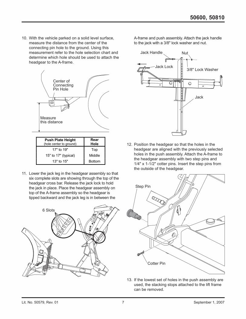
HYDRAULIC FITTINGS
Do not use thread sealant/tape on hoses and fittings.This could damage the product. Install all fittings intorams and hydraulic unit using the following procedureand fitting orientation illustrations:
1. Remove the plug from ram or manifold port. Use arag to catch residual fluid when removing themanifold plugs.
2. Turn the jam nut on the fitting as far back aspossible.
3. Lubricate the O-ring with clean hydraulic fluid.
15°
Cap
90° Elbows
90° Elbows
Long 90°Elbows
Long 90°Elbows
HydraulicUnit
15°
15°
25°
30°
5°
30°30°
10°
20°
PS Angle Ram
90°Elbow
Lift Ram
90°Elbow
15°20°
DS Angle Ram
90°Elbow
0° 0°
90° Elbow (Base)
90° Elbow (Base)
Long 90° Elbow (Rod)
DS Wing Ram PS Wing Ram
Manifold
Fitting
Orifice Plate
Manifold
Fitting
Orifice Plate
PS Wing Rod (inside)
DS Wing Rod (inside)
4. Install the hexagonal orifice plate under each ofthe two wing rod fittings as shown below. The slotin the orifice plate must face the manifold.Installing the orifice plates backwards will causeblade wings to "chatter" when retracting.
5. Screw the fitting into the port by hand as far as itwill go. The washer should contact the port faceand shoulder of the jam nut threads.
6. Unscrew the fitting to proper position, no morethan one full turn.
7. Use one wrench to hold the fitting body in positionand tighten the jam nut with another wrench untilthe washer again contacts the port face. Tighten1/8–1/4 turn to lock the fitting in place.
Lit. No. 50579, Rev. 01 9 September 1, 2007
50600, 50810
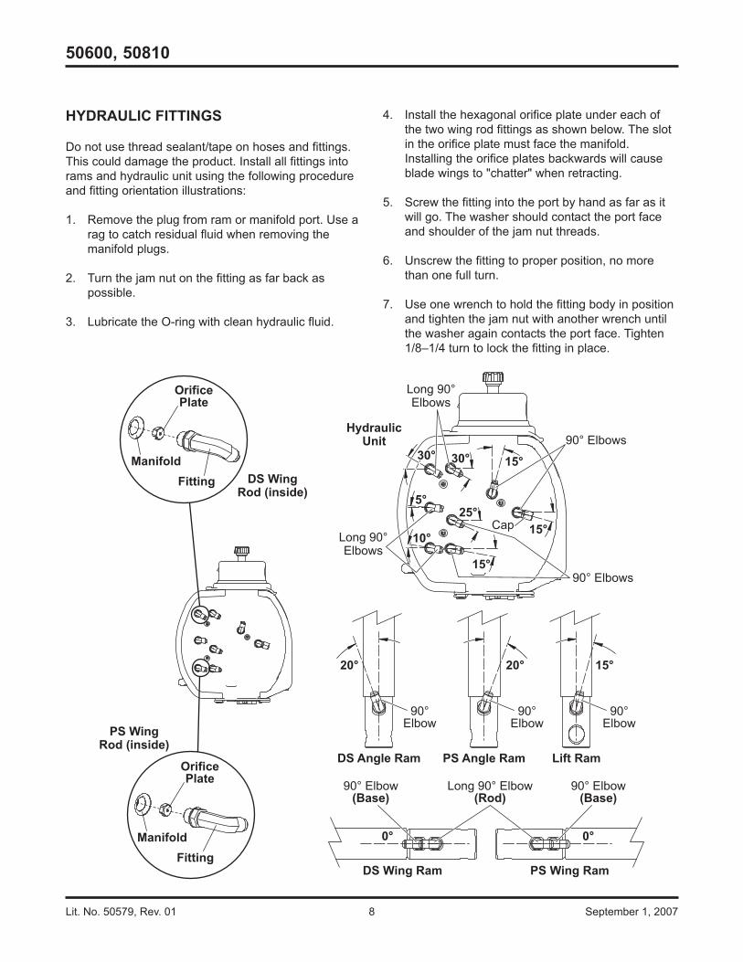
HYDRAULIC HOSES
Do not use thread sealant/tape on hoses and fittings.This could damage product.
1. Apply the caution label to each wing hose near thewing ram fitting, as shown below.
2. Attach all hoses to fittings, routing hoses asshown. Leave the hoses finger tight at this time.
3. Apply two protective hose wraps to each group ofhoses from the fitting side of the hydraulic unitaround and behind the jack leg and hydraulic unitand over the headgear to the front. Apply onehose wrap to each set of wing ram hosesbeginning near the wing ram fittings.
4. Using a wrench to hold the hose end in position,tighten all hose fittings 1/8–1/4 turn past fingertight.
3/8" x 57" HoseTo PS WingRod (inside)
3/8" x 45" HoseTo DS Angle Ram
3/8" x 42" HoseTo PS Angle Ram
3/8" x 60" HoseTo DS Wing
Base (outside)
3/8" x 60" HoseTo DS WingRod (inside)
3/8" x 57" HoseTo PS Wing
Base (outside)
1/4" x 18" HoseTo Lift Ram
Wrap label around hose and press ends together.
CAUTIONCAUTION! Verify hoses from cylinder areconnected to correct manifold port or cylinder willbend. The extend port is closest to the rod and theretract port is closest to the base.
CAUTIONAssembling a hose to the incorrect wing ramport can result in permanent damage to theram.
Lit. No. 50579, Rev. 01 10 September 1, 2007
50600, 50810
HEADLAMPS
Headlamps, hardware and instructions are found inthe headlamp box.
1. Attach the headlamps to the hole and slot in theheadgear light bracket by following the instructionsincluded with the headlamps.
2. Secure the snowplow harnesses and cables to theheadgear as shown.
3. Install the cable boot onto the headgear bracket.
Cable Ties
Cable Ties
CableTie
Cable Boot
SnowplowLightingHarness
SnowplowBattery Cable
WARNINGYour vehicle must be equipped with snowplowheadlamps and directional lights.
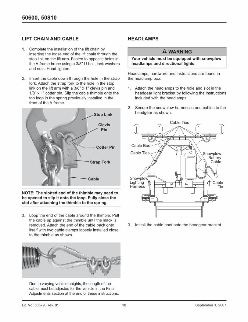
LIFT CHAIN AND CABLE
1. Complete the installation of the lift chain byinserting the loose end of the lift chain through thestop link on the lift arm. Fasten to opposite holes inthe A-frame brace using a 3/8" U-bolt, lock washersand nuts. Hand tighten.
2. Insert the cable down through the hole in the strapfork. Attach the strap fork to the hole in the stoplink on the lift arm with a 3/8" x 1" clevis pin and1/8" x 1" cotter pin. Slip the cable thimble onto thetop loop in the spring previously installed in thefront of the A-frame.
NOTE: The slotted end of the thimble may need tobe opened to slip it onto the loop. Fully close theslot after attaching the thimble to the spring.
3. Loop the end of the cable around the thimble. Pullthe cable up against the thimble until the slack isremoved. Attach the end of the cable back ontoitself with two cable clamps loosely installed closeto the thimble as shown.
Due to varying vehicle heights, the length of thecable must be adjusted for the vehicle in the FinalAdjustments section at the end of these instructions.
Stop Link
ClevisPin
Cotter Pin
Strap Fork
Cable

Lit. No. 50579, Rev. 01 11 September 1, 2007
50600, 50810
WARNINGKeep 8' clear of the blade drop zone when it isbeing raised, lowered or angled. Do not standbetween the vehicle and blade or directly infront of blade. If the blade hits you or drops onyou, you could be seriously injured.
WARNINGTo prevent accidental movement of the blade,always turn the ON/OFF switch to OFFwhenever the snowplow is not in use. Thecontrol indicator light will turn off.
CAUTIONDo not mix different types of hydraulic fluid.Some fluids are not compatible and may causeperformance problems and product damage.
CAUTIONDO NOT raise blade at this time as this maycause pump cavitation.
FLUID CAPACITY• Insta-Act® Unit Reservoir 1-3/4 quarts• Insta-Act System Total 2-3/8 to 2-3/4 quarts
FILLING HYDRAULIC UNIT
1. Attach the snowplow tothe vehicle according tothe instructions on theheadgear.
2. With wing and lift ramsfully retracted, fill thereservoir with FISHER®
EZ Flow Hydraulic Fluid to–40°F (–40°C), or otherfluid conforming to MilitarySpecification MIL-H-5606A, such as Mobil AeroHFA or Shell AeroShell® Fluid 4. Replace the fillplug.
NOTE: Add fluid only when all rams are retracted.
3. Turn the control ON and completely extend andretract the driver-side wing several times. Repeatfor the passenger-side wing. With wings and liftram fully retracted, turn the control OFF.
4. Fill the reservoir with hydraulic fluid. Replace thefill plug.
NOTE: Remove fill plug slowly to relieve anypressure in reservoir.
5. Turn the control ON and raise and lower thesnowplow several times. Activate the controlFLOAT function and manually collapse the lift ramall the way after each lowering of blade. Angle theblade fully to the left and right several times. Withwing and lift rams fully retracted, turn the controlOFF.
6. Fill the reservoir to the top of the fill hole andreplace the fill plug.
FillPlug
Drain Cap
AeroShell® is a registered trademark (®) of Shell Oil Company.
Lit. No. 50579, Rev. 01 12 September 1, 2007
50600, 50810
WARNINGKeep 8' clear of the blade drop zone when it isbeing raised, lowered or angled. Do not standbetween the vehicle and blade or directly in frontof blade. If the blade hits you or drops on you, youcould be seriously injured.
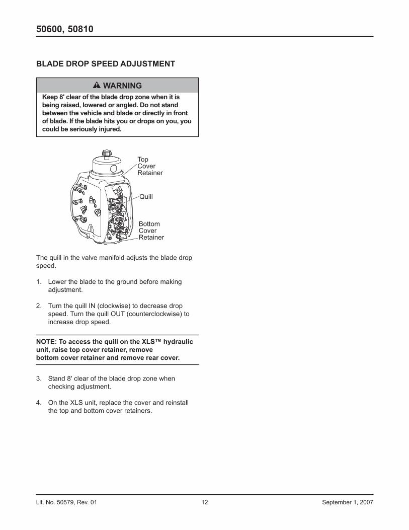
BLADE DROP SPEED ADJUSTMENT
The quill in the valve manifold adjusts the blade dropspeed.
1. Lower the blade to the ground before makingadjustment.
2. Turn the quill IN (clockwise) to decrease dropspeed. Turn the quill OUT (counterclockwise) toincrease drop speed.
NOTE: To access the quill on the XLS™ hydraulicunit, raise top cover retainer, removebottom cover retainer and remove rear cover.
3. Stand 8' clear of the blade drop zone whenchecking adjustment.
4. On the XLS unit, replace the cover and reinstallthe top and bottom cover retainers.
Quill
Bottom Cover Retainer
Top Cover Retainer

Lit. No. 50579, Rev. 01 13 September 1, 2007
50600, 50810
FINAL ADJUSTMENTS
1. With the snowplow attached to the properlyballasted vehicle and the blade lowered to theground, the A-frame should be parallel with theground.
2. Adjust the length of the lift chain so the A-framehits the A-frame stop when the lift ram is fullyraised (10"). Tighten U-bolts.
10"
3. For reliable operation and to prevent damage tothe 6-1/2" lift arm extension spring, the length ofthe cable must be adjusted when attached to thevehicle it will be used on. With the lift ram fullycollapsed, wrap the cable tightly around thethimble, shorten/lengthen the cable to remove allslack from the cable, then tighten the cableclamps.
4. After adjustment, the excess cable should betrimmed off close to the second cable clamp.Cover cut end of cable with electrical tape.Excessive spring tension will make attaching/detaching difficult and overextend the spring.
5. Fully angle the blade in raised and loweredpositions. Adjust hose fittings and wraps so hosesdo not contact vehicle bumper, have no sharpbends and are wrapped at contact points withheadgear and blade.
Lit. No. 50579, Rev. 01 14 September 1, 2007
50600, 50810
VEHICLE LIGHTING CHECK
1. Verify the operation of all vehicle front lighting priorto connecting the snowplow harness.
2. Check the operation of the snowplow lights withsnowplow mounted to vehicle and all harnessesconnected.
Turn signals and parking lamps
Parking lamps ON:• Both vehicle and snowplow parking lamps
should be ON at the same time.
Driver-side turn signal ON:• Both vehicle and snowplow driver-side turn
signal lamps should flash at the same time.
Passenger-side turn signal ON:• Both vehicle and snowplow passenger-side
turn signal lamps should flash at the same time.
Headlamps
Move vehicle headlamp switch to the"ON" position. Connecting and disconnecting thesnowplow lighting harness plug should switch thelights between vehicle and snowplow as follows:
Snowplow lighting harness DISCONNECTED:• Vehicle headlamps should be ON.• Snowplow headlamps should be OFF.
Snowplow lighting harness CONNECTED:• Snowplow headlamps should be ON.• Vehicle headlamps should be OFF.
Dimmer switch should toggle headlamps betweenhigh and low beams. The high beam indicator onthe dash should light when headlamps are placedin high beam.
Daytime Running Lamps (DRLs)
An operational check of the vehicle and snowplowDRLs will depend on the vehicle model, vehicleDRL system and type of Isolation Module installed.Due to the variations in the OEM DRL systemsand the different Isolation Module options
available, checking the functionality of thesnowplow DRLs will depend on the type of moduleinstalled on the vehicle.
With headlamp switch OFF, activate the vehicleDRLs.
Snowplow lighting harness DISCONNECTED:• Vehicle DRLs should be ON.• Snowplow headlamps should be OFF.
Snowplow lighting harness CONNECTED andvehicle in DRL mode:
• Check snowplow DRL function per the type ofIsolation Module installed.
Refer to the Mechanic's Guide for information onthe Isolation Module DRL functions.
Hand-Held Control
The snowplow plugs do need to be connected tothe vehicle harness connectors. The controlindicator light should light whenever the controlON/OFF switch and the ignition (key) switches areboth in the "ON" position.
3. Connect all snowplow and vehicle harnesses.Raise the snowplow and aim snowplowheadlamps according to the Snowplow HeadlampBeam Aiming instructions included with theheadlamps and any state or local regulations.
4. Check aim of vehicle headlamps with snowplowremoved.
5. When the snowplow is removed from the vehicle,install plug covers on the vehicle battery cable andlighting harness. Insert the snowplow battery cableand lighting harness into the cable boot on thesnowplow.
CAUTIONOn 2-plug electrical systems, plug covers shallbe used whenever snowplow is disconnected.Vehicle Battery Cable is 12-volt unfused source.

Lit. No. 50579, Rev. 01 15 September 1, 2007
50600, 50810
OWNER'S MANUAL PACKET
If the completed snowplow will be deliveredimmediately, the Owner's Manual should be reviewedwith and given to the purchaser.
If the snowplow is completed prior to delivery to thepurchaser, attach the Owner's Manual Packet to theelectrical cable of the cab control for safekeeping.

Lit. No. 50579, Rev. 01 16 September 1, 2007
50600, 50810
Fisher Engineering reserves the right under its product improvement policy to change construction or design details and furnish equipment whenso altered without reference to illustrations or specifications used. Fisher Engineering or the vehicle manufacturer may require or recommendoptional equipment for snow removal. Do not exceed vehicle ratings with a snowplow. Fisher Engineering offers a limited warranty for all snowplowsand accessories. See separately printed page for this important information. The following are registered (®) or unregistered (™) trademarks ofDouglas Dynamics, L.L.C.: FISHER®, Insta-Act®, Minute Mount® 2, XLS™.
Printed in U.S.A.
Related Documents