RD-Fl149 224 ELECTROMAGNETIC SCATTERING BY ARBITRARILY SHAPED i/i REFLECTORS: SUBREFLECTOR.-CU) MASSACHUSETTS INST OF AD-' 49 24 TECH LEXINGTON LINCOLN LRB A R DION ET AL. 31 OCT 84 UNCLASSIFIED TR-662 ESD-TR-4-58 F9628-85-C-82 F/G 28/4 N Eso EhhhIsEhE EhhhhhhhhhhhhE '-"'IEEE'...m

Welcome message from author
This document is posted to help you gain knowledge. Please leave a comment to let me know what you think about it! Share it to your friends and learn new things together.
Transcript

RD-Fl149 224 ELECTROMAGNETIC SCATTERING BY ARBITRARILY SHAPED i/iREFLECTORS: SUBREFLECTOR.-CU) MASSACHUSETTS INST OF
AD-' 49 24 TECH LEXINGTON LINCOLN LRB A R DION ET AL. 31 OCT 84
UNCLASSIFIED TR-662 ESD-TR-4-58 F9628-85-C-82 F/G 28/4 N
Eso EhhhIsEhEEhhhhhhhhhhhhE'-"'IEEE'...m
W'I 111112.2
2.8
1111_I2 1111L 111111.6
MICROCOPY RESOLUTION TEST CHART
NATIONAL BUREAU OF STANDARDS 196 A
0)
I
AE~ Gn 2-_/2a [e2Tr(r k+Rk) A + it/2]
S- [ PG/4X 2 ] 1/2 a[wrk • rk ) gk+k (6)
rk k
The field scattered by the reflector is the sum of the elemental field
contributed by each patch, taking into account the polarization of each con-
tributor. The polarization of the field radiated by a patch is determined by
the incident ray polarization and its transformation on reflection which is
given by (Ref. 3):
; . t .4 +* I4
I
MASSACHUSETTS INSTITUTE OF TECHNOLOGYLINCOLN LABORATORY
ELECTROMAGNETIC SCATTERING BY ARBITRARILYSHAPED REFLECTORS: SUBREFLECTOR EFFICIENCY
A.R. DION
L.V. MURESA N
Group 61
I
TECHNICAL REPORT 662
31 OCTOBER 1984
' DTICIII ELECTE
Approved for public release; distribution unlimited. S JAN 1 I
IS
r'" B
LEXINGTON MASSACHUSETTS
['

ABSTRACT
A general expression for the electromagnetic scattering by an arbitrary
shaped reflector is developed and applied in a computer model of offset hyper-
boloid reflectors. The computed scattering is shown to be in excellent agree-
ment with scattering measurements made on an offset reflector of projected
diameter - 24 cm, at frequencies of 10.35 GHz, 20.7 GHz and 44.5 GHz. Next,
using the computer model, the efficiency of the subreflector in a dual-
reflector antenna is calculated as a function of subreflector diameter and for
two values of illumination taper. For subreflectors truncated at the ray-
S optics boundary the calculated efficiency is 0.83 and 0.91, respectively, for
truncation diameter of 7.7 X and 30.4 X, with 5 dB of illumination taper;
these respective efficiencies increase to 0.91 and 0.95 with 12 dB of illumin-
ation taper. However, subreflectors of diameter about two wavelengths larger
than the ray-optics diameter have very nearly unit efficiency.
/ /
Aoossiotl For
* ITIS GRA&IDTIC TABUnannoImcedj u s t i b i f.t I , - -
0 Distribut I
D t
iii
. .
CONTENTS
Abstract ii
Illustrations v
1.0 Introduction I
2.0 Analysis 5
2.1 Basic formulation for computer modelling 5
2.2 Total field 12
2.3 Geometrical optics solution for offset hyperboloids 13
2.4 Application to specific cases 15
3.0 Experimental Offset Hyperboloidal Reflector 19
3.1 Results 24
4.0 Effect of Subreflector Diameter on Gain of Dual Reflector Antennas 28
5.0 Conclusions 33
References 34
Sv
S°
6
J,.V
6
ILLUSTRATIONS
Figure je
1. EHF multiple beam antenna. 2
2a. Arbitrary reflector and feed illustrating typical patch. 6
2b. Reflected wavefront near a patch. 8
3. Geometry for far-field analysis. 10
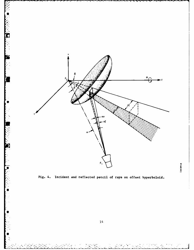
4. Incident and reflected pencil of rays on offset hyperboloid. 14
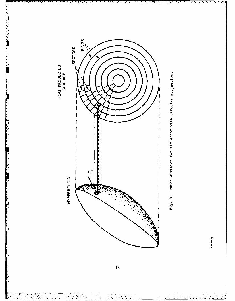
5. Patch division for reflector with circular projection. 16
6. Scattering by axially symmetric hyperboloid reflector. 18
• 7. Geometry of offset hyperboloidal reflector and field coordinate
system. 20
8. Feed and reflector arrangement for scattering pattern
measurements. 21
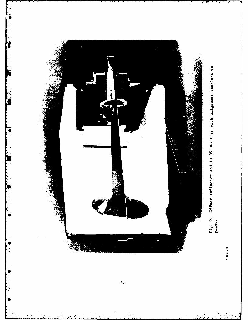
9. Offset reflector and 10.35-GHz horn with alignment template in
S"place. 22
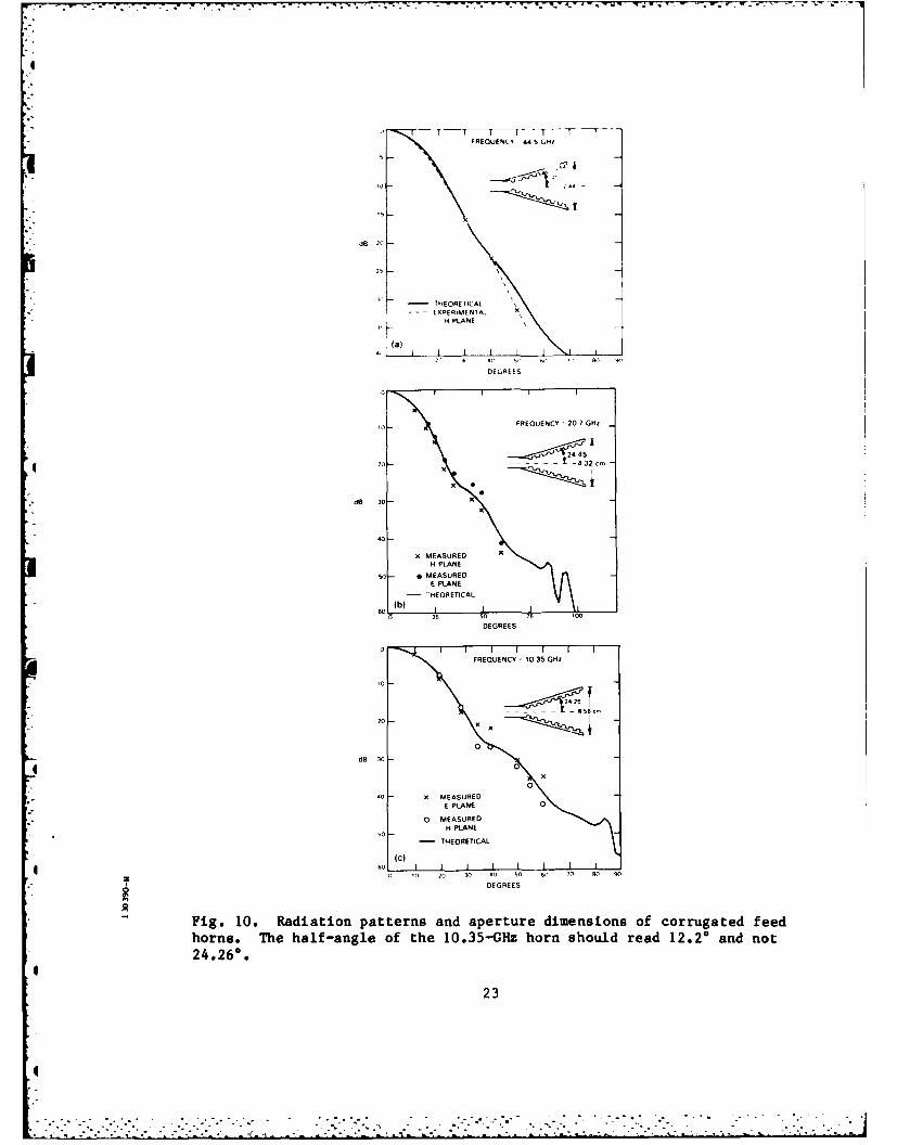
10. Radiation patterns and aperture dimensions of corrugated feed
*horns. The half-angle of the 10.35-GHz horn should read 12.20
and not 24.26. 23
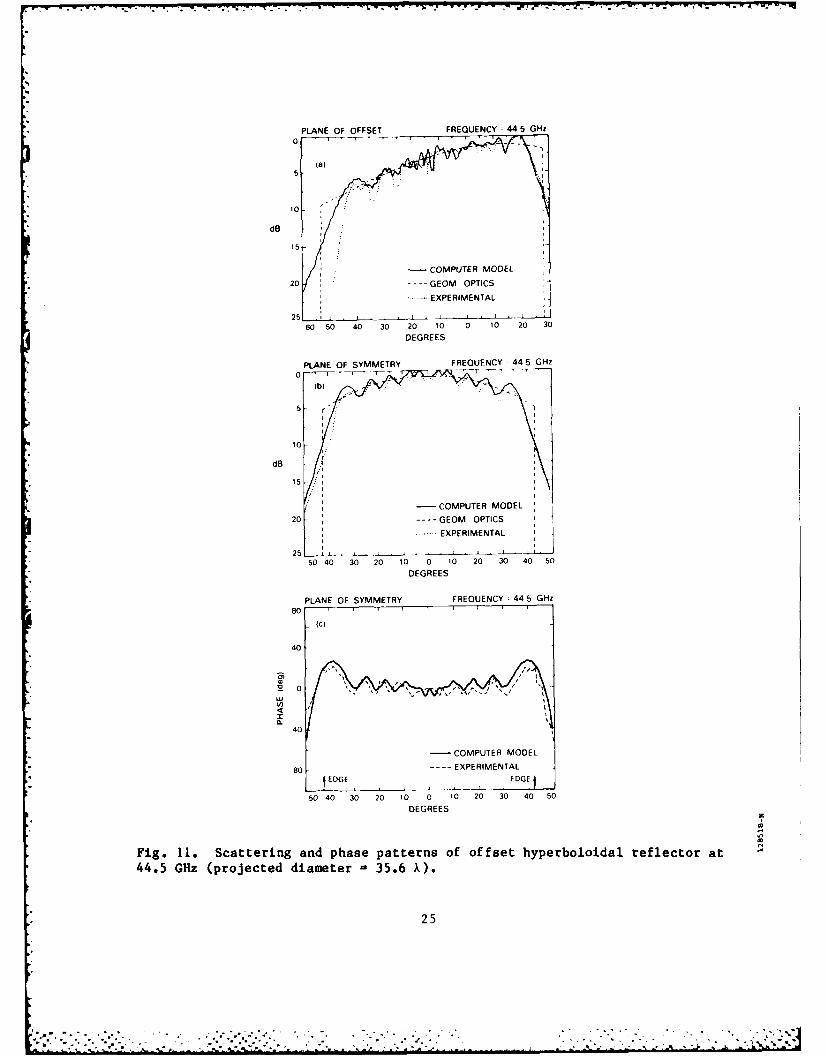
11. Scattering and phase patterns of offset hyperboloidal reflector
at 44.5 GHz (projected diameter - 35.6 X). 25
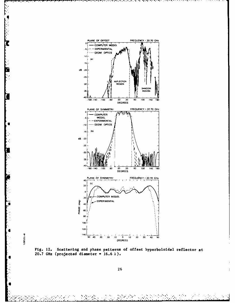
12. Scattering and phase patterns of offset hyperboloidal reflector
at 20.7 GHz (projected diameter - 16.6 X). 26
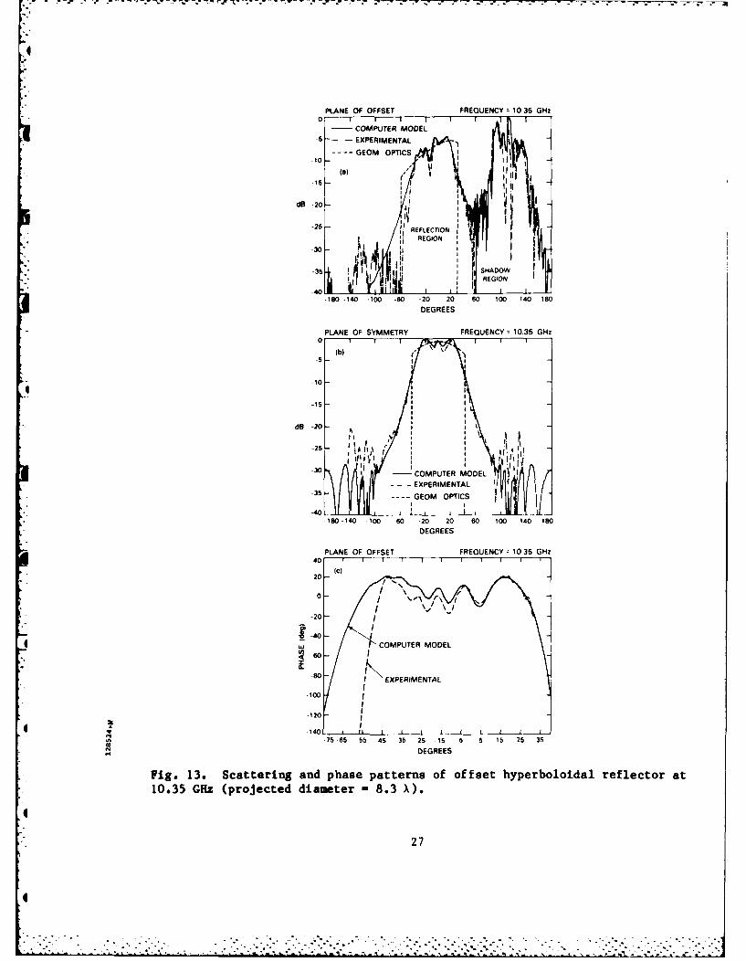
13. Scattering and phase patterns of offset hyperboloidal reflector
at 10.35 GHz (projected diameter - 8.3 X). 27
14. Relevant parameters for subreflector efficiency analysis. 29
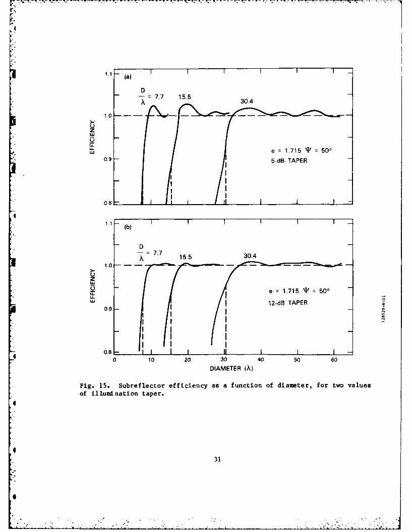
* 15. Subreflector efficiency as a function of diameter, for two values
of illumination taper. 31
v
t. vi
0'

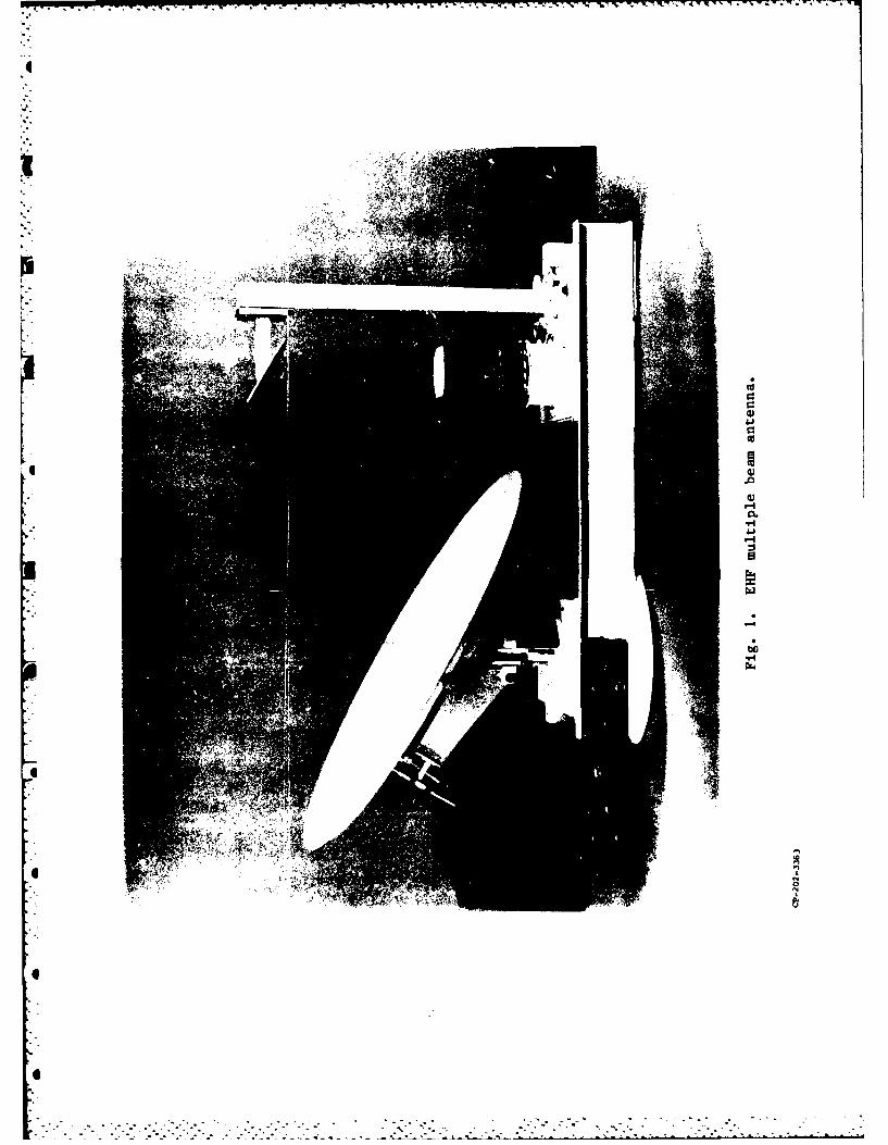
1.0 INTRODUCTION
Offset, dual-reflector antennas are finding increased applications,
particularly in satellite communications systems. An example is the casse-
grain, EHF, multiple-beam antenna depicted in Fig. 1, which consists of an
offset paraboloid reflector, an hyperboloidal subreflector and a 4 x 4 array
of feed horns. The beam produced by this antenna is shaped to cover a desired
area on the earth from a synchronous altitude satellite.
The subreflector of a dual-reflector antenna is generally made a little
larger than the boundary determined by the intersection of the subreflector
with the focal cone of rays bounding the reflector (ray-optics boundary). The
slightly larger size is required to compensate for the effects of edge dif-
fraction, which would reduce antenna gain if the subreflector was truncated at
the ray-optics boundary. On the other hand, making the subreflector much lar-
ger than the ray-optics boundary is generally detrimental due to either
increased blockage of secondary radiation or increased weight and size. The
determination of the minimum size of the subreflector in a dual-reflector
antenna is a subject treated in this report. It will be shown, in particular,
that truncation of the subreflector at the ray-optics boundary causes appre-
ciable loss of antenna gain, due to subreflector edge diffraction, but trun-
cation at least one wavelength beyond this boundary renders the loss negli-
gible. This result was obtained by physical-optics analysis, using a computer
modelling technique which was also used in a related study of scattering by
-1-
4
Cu000UCC
Ua,
.0
a,
0.WIU
a
-4
Pt.'
I
N
*0
C
C
- N N - * -
'
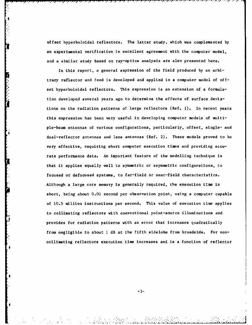
offset hyperboloidal reflectors. The latter study, which was complemented by
an experimental verification in excellent agreement with the computer model,
and a similar study based on ray-optics analysis are also presented here.
In this report, a general expression of the field produced by an arbi-
trary reflector and feed is developed and applied in a computer model of off-
set hyperboloidal reflectors. This expression is an extension of a formula-
tion developed several years ago to determine the effects of surface devia-
tions on the radiation patterns of large reflectors (Ref. 1). In recent years
this expression has been very useful in developing computer models of multi-
ple-beam antennas of various configurations, particularly, offset, single- and
dual-reflector antennas and lens antennas (Ref. 2). These models proved to be
very effective, requiring short computer execution times and providing accu-
rate performance data. An important feature of the modelling technique is
that it applies equally well to symmetric or asymmetric configurations, to
focused or defocused systems, to far-field or near-field characteristics.
Although a large core memory is generally required, the execution time is
short, being about 0.01 second per observation point, using a computer capable
of 10.5 million instructions per second. This value of execution time applies
to collimating reflectors with conventional point-source illuminations and
provides for radiation patterns with an error that increases quadratically
from negligible to about 1 dB at the fifth sidelobe from broadside. For non-
collimating reflectors execution time increases and is a function of reflector
-3-
size in wavelengths. For the largest subreflector included in this study the
execution time was -0.1 second per observation point.
The computer model of offset hyperboloidal reflectors was validated by
scattering measurements made on the subreflector of the antenna shown in
Fig. 1. Corrugated, conical horns were used to illuminate the offset
reflector with a taper of about 5 dB, at frequencies of 44.5 GHz, 20.7 GHz and
10.35 GHz, corresponding to projected diameter-to-wavelength ratios of about
35.6, 16.6 and 8.3, respectively.
i
i-4
I
" '.. . ." : . •. , . , ** -

2.0 ANALYSIS
2.1 Basic Formulation for Computer Modelling
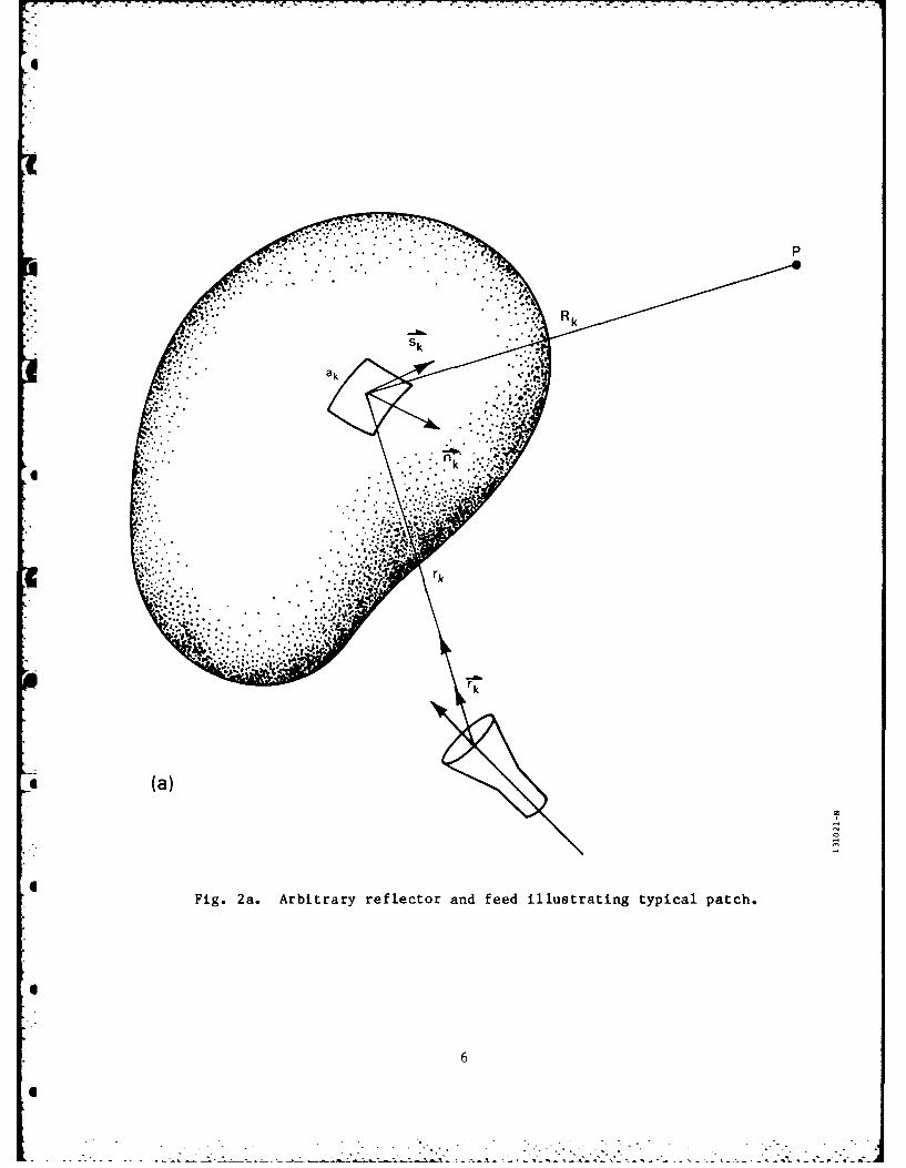
Let the arbitrary shaped reflector of Fig. 2a be illuminated by a feed
with input power P and directivity G, and let its surface be divided into N
patches of approximately equal area, ak, and of dimensions small enough so
that over the extent of a patch the incident field is essentially uniform.
The power, Pk, intercepted by the kth patch is then:
PG gk k(nk " r(k)Pk =Mr (1)1
k ~ 4irr2k
where G 2gk is the feed directive gain in the directic the patch,
ak(nk rk ) is the area of the patch projected in a plane
normal to the direction of incidence,
nk is the unit vector normal to the patch at its center
rk is the unit vector specifying the incident ray direction,
rk is the distance between the feed and the patch centers.
At the center of the patch, the phase of the incident field is delayed with
respect to the field at the feed aperture by
i . 2t rk/A (2)k
Consider next the reflected wave at a patch and assume it to be plane in
the vicinity of the patch. This assumption is valid for collimating
reflectors, whatever the patch size. For non-collimating reflectors the con-
dition of a reflected plane wave is an approximation whose accuracy increases
with decreasing patch size. In the vicinity of a patch, the reflected field
can be considered to be the segment a'k of a plane wave, as illustrated in
-5-
IP
* (a)
iSir
Fig. 2a. Arbitrary reflector and feed illustrating typical patch.
66
6o. .•
• 6
6 % °
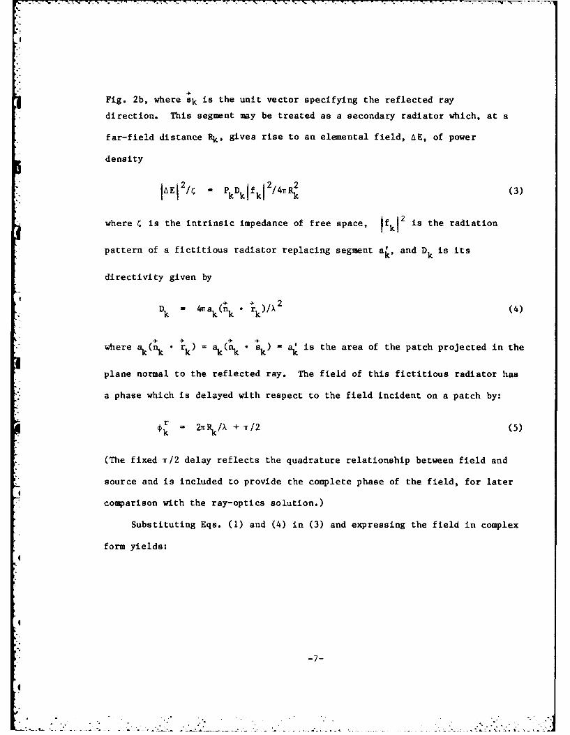
Fig. 2b, where sk is the unit vector specifying the reflected ray
direction. This segment may be treated as a secondary radiator which, at a
far-field distance Rk , gives rise to an elemental field, AE, of power
density
2 2 2 2s eraito2E P k D kfkI2/4rR (3)
where is the intrinsic impedance of free space, fk is the radiation
pattern of a fictitious radiator replacing segment a', and Dk is its
directivity given by
+ 2
Dk = 4, aknk r()/ (4)
where ak(nk r k ) - ak( k ) a. is the area of the patch projected in the
plane normal to the reflected ray. The field of this fictitious radiator has
a phase which is delayed with respect to the field incident on a patch by:
i r= 2iRk/X + iT/2 (5)
(The fixed iT/2 delay reflects the quadrature relationship between field and
source and is included to provide the complete phase of the field, for later
comparison with the ray-optics solution.)
Substituting Eqs. (1) and (4) in (3) and expressing the field in complex
form yields:
I
i" -7-
- ""e- "2x

r 2- 77-T-w.-
. . .... .. '..... . .. ..
.. ~ ... I...... .
..........,* ~~ .a ................. ... ... ............
.... .. .. .. .... W .. ..
V..n
Fig. 2b. Reflected wavefront near a patch.
8

2E - [1PG/4v 2 ]1/2 + + -J[21(rk+Rk)/ + i/2]A CG4X a k(a k "rk) gkfk e
(6)
r kRk
The field scattered by the reflector is the sum of the elemental field
contributed by each patch, taking into account the polarization of each con-
tributor. The polarization of the field radiated by a patch is determined by
the incident ray polarization and its transformation on reflection which is
given by (Ref. 3):
+ + + +
E r = (n k ' Egi ) n k - (n k x E i ) x n k (7)
where Er and ti are, respectively, the reflected and incident field
on a patch. The field radiated by a patch has complex amplitude given by
Eq. (6) and polarization given by Eq. (7) and must be resolved into three
orthogonal components for summation. However, as the point of observation
recedes from the reflector, all contributions become polarized in the plane
transverse to the direction of propagation, leaving two components of polari-
zation to be summed. In the application that follows the reflected field is
considered polarized in the same direction everywhere and, therefore, the far
field at distance R is (see Fig. 3):
2 21/2E F[PG /4t R X1 (8)
where
-9-

IT 7
S2k*
6 Fg.3. eoetr fr fr-iel aalyis
4r
Ir
10k
IG
-j[ 2 w (rk - k )/X + r/2Jk Pk
Sak(nk rk) gkfkek-i rk
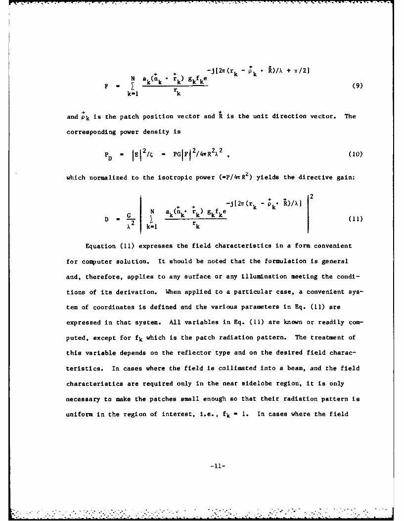
and Pk is the patch position vector and R is the unit direction vector. The
corresponding power density is
- - PGIF12/ 4rR2A2 ,(10)
which normalized to the isotropic power (-P/47rR 2) yields the directive gain:
+• + -j [2w (r k - p R)/XN ak(n. rk) g k k 2
X2 kI k
Equation (11) expresses the field characteristics in a form convenient
for computer solution. It should be noted that the formulation is general
and, therefore, applies to any surface or any illumination meeting the condi-
tions of its derivation. When applied to a particular case, a convenient sys-
tem of coordinates is defined and the various parameters in Eq. (11) are
expressed in that system. All variables in Eq. (11) are known or readily com-
puted, except for fk which is the patch radiation pattern. The treatment of
this variable depends on the reflector type and on the desired field charac-
teristics. In cases where the field is collimated into a beam, and the field
characteristics are required only in the near sidelobe region, it is only
necessary to make the patches small enough so that their radiation pattern is
uniform in the region of interest, i.e., fk I 1. In cases where the field
-11-
"- . . . -. . . " .,- - , -.-. . ...- -" - -. -. . . S ,..-.
produced by the reflector is divergent and the field characteristics are
desired over a wide angular region, the patch size must be made smaller and an
appropriate expression for fk must be used. One such case is the applica-
tion that follows where it was found necessary to make the patch size slightly
smaller than one wavelength, and where the patch radiation pattern was taken
"* equal to cos 6, where 0 is the angle measured from the reflected ray direc-
tion. In this application the patches essentially reduce to Huygens sources.
The number of patches, N, must be chosen so that the conditions of a
plane reflected wave in the vicinity of the patches, and of uniform amplitude
*I illumination over a patch are satisfied, as well as the condition previously
stated for the choice of fk" The number of patches required is best deter-
mined by tests where N is increased until convergence is reached within a spe-
cified error. For the practical case of the collimating reflector with con-
*i ventional illumination taper, and modelled with isotropically radiating
* patches (fk - 1), the error increases quadratically with angle from bore
- sight and is about I dB at an angle equal to .25 N beamwidths.
2.2 Total Field
The total field is the sum of the direct field from the feed and of the
s field scattered by the reflector as given by Eq. (8). However, the field that
exists in the shadow region of the reflector is that caused by diffraction
around the reflector. In this region the field was calculated by applying
* Babinet's principle (Ref. 4) which allows replacement of the reflector by its
complementary aperture in an infinite screen. The field diffracted by this
-12-6
. .. . . . .
aperture may be calculated by integrating over the surface of the reflector,
thus allowing Eq. (8) to be used, but with the patch normal reversed and with
fk - cos 0, where 0 is now measured from the incident ray direction. The
aperture diffracted field thus computed is subtracted from the incident field
(in absence of the screen) to yield the field in the shadow region, as pre-
scribed by Babinet's principle.
2.3 Geometrical Optics Solution for Offset Hyperboloids
In this section, the field reflected by an offset hyperboloid is calcu-
lated by application of geometrical optics principles, which state that a pen-
cil of rays issued from a feed at the external focus F1 is reflected as a pen-
cil of rays coming from a virtual feed at the internal focus F2 . The relevant
geometry is presented in Fig. 4 where the spherical coordinates 0, specify
the direction of observation. Let the directive gain of the feed be Df(a)
and that of the virtual feed be Ds(8), where the incident ray direction, a,
and the reflected ray direction, 8, are measured from the hyperboloid axis,
then for conservation of energy
Df(a) sin ada - D(8) sin 8 da (12)
The incident and reflected ray directions are related by
tan(8/2) = Mtan(c/2) (13)
where M - (1+e)/(1-e) is the magnification factor, and e is the eccentricity
of the hyperboloid. Taking the derivative on both sides of Eq. (13) yields,
da/d8 - cos2 (a/2)/Mcos2 (8/2) (14)
which substituted in Eq. (12), and after some manipulation, gives
D as(0) - Df(a) cos4 (a/2)/M2 cos 4 (8/2) (15)
-13-
- -
2 2
F cF1
0
0
14

To apply Eq. (15), the direction of the reflected ray, 8, is first computed
using
Cos 0 = u• v
+ +
where the unit vectors u and v are, respectively, the direction of observation
and the direction of the hyperboloid axis, in the e, coordinate system. The
corresponding incident ray direction, a, is next computed using Eq. (13), and
together with 8 is substituted in Eq. (15) to provide the directive gain of
the virtual feed in the direction of observation.
2.4 Application to Specific Cases
The general formulation (physical optics) given by Eq. (11) is now
applied to the calculation of the field scattered by an offset hyperboloid.
For this, the surface of the reflector is specified by N patches whose areas,
coordinates and normal at their center must be calculated. For reflectors
projecting into a plane as a circle, which is the case here, the patch para-
meters are obtained by dividing the projected circle into rings of equal
width, and further dividing each ring into sectors of width about equal to the
ring width, such as illustrated in Fig. 5. Projecting the sectors back onto
the hyperboloidal reflector surface then yields the coordinates at the center
* of each patch where the patch normal and area are determined. The feed illu-
minating the reflector is modelled by specifying its aperture center, its axis
direction, its directivity and its radiation pattern. A rectangular coordi-
4 nate system with origin at the internal focus of the hyperboloid is chosen to
4
-15-
4
0
w
CL I
Lw
-g-
441
0
1V4
.4>V-4
16.
I.
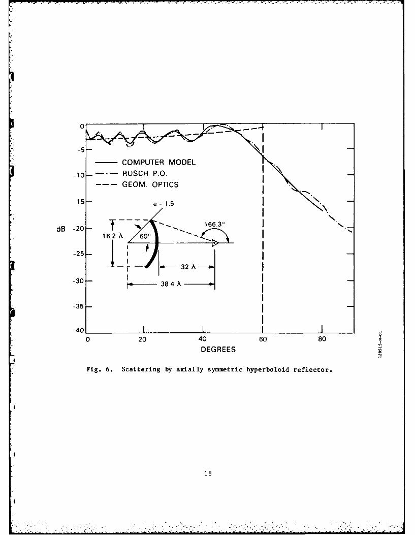
express the geometry of the reflector and feed. The field characteristics are
expressed in a spherical coordinate system with origin also at the internal
focus of the hyperboloid, and therefore at the phase center (geometrical
optics) of the reflected wave. In an initial test of the computer model the
results were found in very good agreement with the analytical results of Rusch
(Ref. 5) for the uniformly illuminated, centered hyperboloid (a special case
of the offset hyperboloid), as indicated by the comparison presented in
Fig. 6.
-17-
, --i : :;, . - - . - - -- - .- . . .. ... • . ... .. - . .. , . ..-- .
-10 - -RUSCH P.O.GEOM. OPTICS
-15 es 1.5
dB-0166.30J
I -- I 2
-30- 1 -3 4
-35I
0 20 40 60 80 Z
DEGREES
Fig. 6. Scattering by axially symmetric hyperboloid reflector.
18
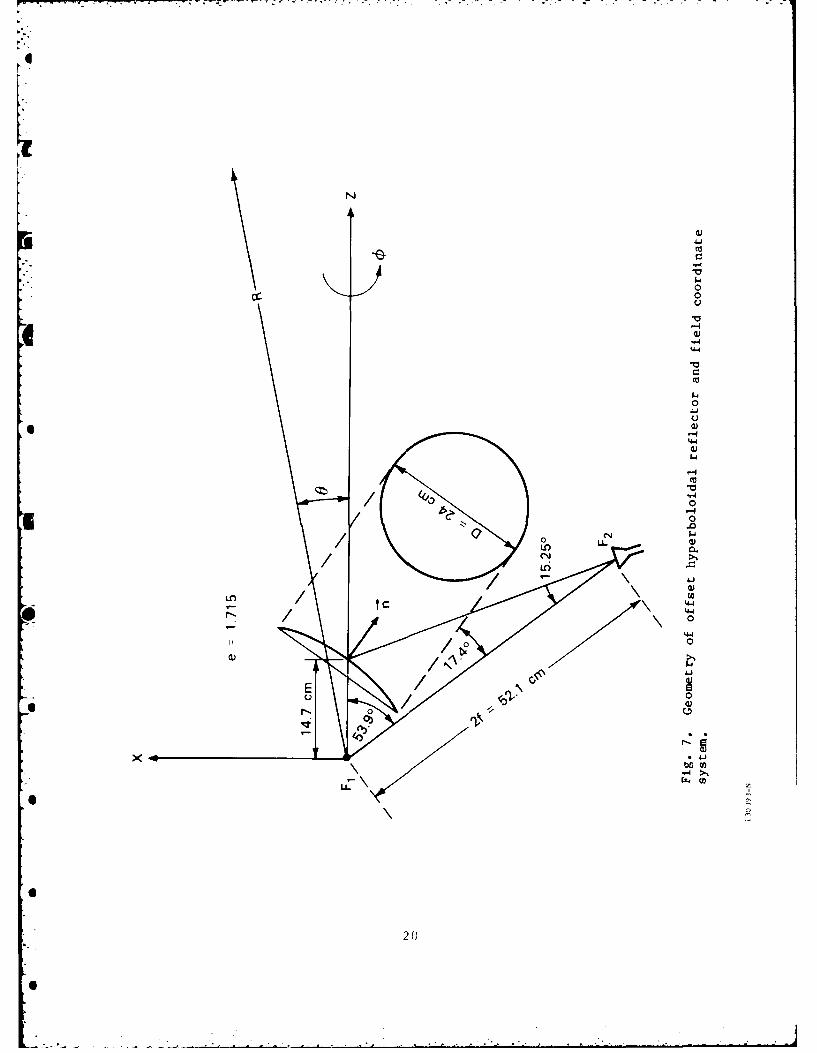
3.0 EXPERIMENTAL OFFSET HYPERBOLOIDAL REFLECTOR
The offset hyperboloid used in the experimental investigation is the sub-
reflector of the offset, dual-reflector antenna presented in Fig. 1. This
hyperboloid is characterized by a distance between focii of 52.1 cm and by an
eccentricity of 1.715. Its perimeter is the intersection with a cylinder of
diameter = 24 cm, whose axis is inclined 17.380 from the hyperboloid axis, as
shown in Fig. 7. The feed is located at the external focus of the hyperboloid
and its axis, at an angle of 15.250 from the hyperboloid axis, is congruent to
the ray which after reflection defines the 8 = 00 direction of the field pat-
tern. Scattering patterns were measured at three frequencies, 44.5 GHz,
20.7 GHz and 10.35 GHz, corresponding to reflector diameters (circular pro-
jection) of 35.6 X, 16.56 X, and 8.28 X, respectively. Measurements were
taken in the principal planes = 0 (the plane of offset), and p = 900 (the
plane of pattern symmetry), and for both parallel and perpendicular polariza-
tions. The feed horn, reflector and mount are shown in Fig. 8. The hyperbo-
loid reflector is mounted on a foam support, and together with the feed horn
rotates about an axis passing through the internal focus as defined in
Fig. 7. In Fig. 9, the reflector is shown with the alignment template used to
ensure correct positioning of the feed at the external focus of the hyperbo-
loid. The feed for each test frequency is a corrugated, conical horn pro-
ducing a taper of about 5 dB at the edge of the reflector. The measured radi-
ation patterns of the three horns and their aperture dimensions are given in
Fig. 10. Also shown in Fig. 10 are the theoretical feedhorn radiation pat-
terns (Ref. 6) used in the scattering calculations, and excellent agreement
is observed over the angular sector subtended by the hyperboloid.
-19-
0
00
LfU)
t c .4-
0
440)
CIOU
0
.J
200

FOAMSUPPORT
Tx -- F
/69.1
2 0/ /
s/ /, / fF2
Fig. 8. Feed and reflector arrangement for scattering pattern* measurements.
21
I
0
-4
00
220
FREDUENCv 44 S G"I
de 22
-
- THEORETICALEXPERIMENTAL X
H PLANE
I-(a) 4C "1 8 0
DEGREES
o T I I
'0 FREQUENCY 20 7 GHi
20 X. . . . - 4 32Cn
d8 30
b40
X MEASURED KH PLANE
50 0MEASUREDEPLANE
- HEORETICAL
0, 25 50 75 0
DEGREES
0
i FREQUENCY 10 35 GH,
0 <
F
0
0 ES RE '
0i I ~~ ~ 2 - x03 05 n7 O9
40 K MEASUREDE PLANE 0
MEASUREDN PLANE
50-THEORETICAL
6 1 (C) I I I I I I I I
Z0 0 20 30 40 50 V 0 w R 90
DEGREES
Fig. 10. Radiation patterns and aperture dimensions of corrugated feedhorns. The half-angle of the 10.35-GHz horn should read 12.20 and not24.260.
23
I
. ..o
3.1 Results
The principal-plane, calculated and measured (perpendicular polarization)
scattering patterns at 44.5 GHz (35.6 X reflector) are shown in Fig. 11. The
agreement is good, except at the lower angles in the offset plane, where the
effect of feed blockage is substantial. Misalignment, stray reflections,
blockage and scattering by the feed and support are believed to account in
great part for the differences observed. Geometrical-optics analysis is seen
to provide accurately the mean value of the field, except at the reflection
region boundary and beyond. At the boundary the intensity of the scattered
field is about 6 dB less than predicted by ray optics. The calculated (phy-
sical optics) and measured phase patterns are also in excellent agreement.
Since the reflector is rotated about its internal focus, i.e., about the
apparent center of reflected rays, the geometrical-optics phase pattern is the
00-phase line. Near the reflection region boundary the phase of the field
predicted by geometrical optics is in error by about 30% The results of
scattering measurements made with parallel polarization of the field are
nearly identical to those obtained with perpendicular polarization, and are
not presented. The measurement region for the 35.6 X reflector included only
the reflection region and part of the diffraction region. However, for the
16.6 X and 8.3 X reflectors, the principal-plane patterns all around the
reflectors were measured and the results, presented in Figs. 12 and 13, show
good agreement with predictions in all regions. The phase patterns, for these6
two reflectors were measured only over the reflection region, and exhibit
somewhat poorer agreement with predictions than for the 35.6 X reflector, but
this is likely due to increased blockage by the physically larger feedhorns.
6
i -24-
6
PLANE OF OFFSET FREQUENCY 44 5 GHz
(a)
10-
dB15 ;"
- COMPUTER MODEL
20 " GEOM OPTICS
......... EXPERIMENTAL
25160 50 40 30 20 10 0 10 20 30
DEGREES
PLANE OF SYMMETRY FREQUENCY 44 5 GHz
(b)
0 4 0 2 0 0 1 0 3 0 5
dB ..
15
-COMPUTER MODEL
20 ---- GEOM OPTICS
..... EXPERIMENTAL
50 40 30 20 10 0 10 20- 30 40 50
DEGREES
PLANE OF SYMMETRY FREQUENCY - 44 5 GHz
80
IC)
40
440
-COMPUTER MODEL
80 EXPERIMENTAL,5 40 30 20 10 0 _ 10 20 30 40 5
DEGREES
Fig. 11o Scattering and phase patterns of offset hyperboloidal reflector at
44.5 GHz (projected diameter = 35.6 X).
25
. . . . . . .. .. . , , """-.,-, , . ... " .. .. ..- . . .. . ..- .. " . .; . . . .
PLANE OF OFFSET FREQUENCY 20 70 GM:0 I I I I . I . I I
- COMPUTER MODEL
-s--EXPERIMENTALI
-10 GEOM OPTICS-a0
-is
dIB-20 III *
-25
Ii REFLECTION I-30 f~ REGION II
ISHADOW-35 ifREGION
-180-140 -100 -60 -20 20 60 100 140 180DEGREES
PLANE OF SYMMETRY FREQUENCY 20 70 GM:
.- COMPUTER-5 MODEL
- -EXPERIMENTAL
*i -1--GEOM OPTICS
-15 - (b)
d8 -20 -
-25I
-30
-40 IfiIl-180 -140 -100 -60 -20 20 60 100 140 180
DEGREES
PLANE OF SYMMETRY FREQUENCY= 20 70 GM:
EXPERIMENTAL
66
* -120L
-50 40 30 20 10 0 10 20 30 40 50
DEGREES
Fig. 12. Scattering and phase patterns of offset hyperboloidal reflector at20.7 GHz (projected diameter -16.6 A).
62
PLANE OF OFFSET FREQUENCY= 10 35 G~z0
- COMPUTER MODEL
-5--EXPERIMENTAL
-0 GEOM OPTCS
In)
dB -20
-25: -
-26 REFLECTION
-305 SHADOW
-20 20 EGION
-40 ______________
-180 -140 -100 -60 -2 0 60 100 140 180DEGREES
PLANE OF SYMMETRY FREQUENCY 1035 GHz0
-to-
dB8-20- I
-25 41. 4I
I3 COMPUTER MODEL I
--- EXPERIMENTAL-35 -GEOM OPTICS
-40-180 -140 -100 -0 -20 20 60 100 140 180
DEGREES
PLANE OF OFFSET FREQUENCY= 10 35 GHz40
20-
20-
II~ COMPUTER MODEL
IM
R M O E
a(
so / XEIMNA
DEGREES
Fig. 13. Scattering and phase patterns of offset hyperboloidal reflector at
10.35 G~z (projected diameter -8.3 X).
27

4.0 EFFECT OF SUBREFLECTOR DIAMETER ON GAIN OF DUAL REFLECTOR ANTENNAS
For reasons of blockage of secondary radiation, or of weight and size,
the subreflector of a dual-reflector antenna is, generally, made only as large
as is required to optimize performance, and the design guideline has been to
truncate the subreflector about one wavelength beyond the ray-optics bound-
- ary. In this section, the effect of the subreflector size on the gain of a
dual-reflector antenna is calculated, with results that justify the design
guideline. The calculations are made for a center-fed, cassegrain antenna,
using the computer model previously described. The relevant antenna para-
meters are given in Fig. 14. The directivity of the dual-reflector antenna is
* calculated for values of subreflector diameter in the vicinity of the ray-
optics value, and does not include blockage effects.
Following Silver (Ref. 7), the directivity of the dual-reflector antenna
may be expressed as
D a = cot2 (/2) f E(W) tan (8/2) d8 (17)
where T is the paraboloid half-angle and E(a) is the physical-optics solution
for the field scattered by the subreflector, which according to Eq. 11, is,
1/2 N an k rk ) gkfke k k
E()- Ep) (a)r (18)
0
-28-
0!
* - . - -* * * *,..**--'.*.* ,--

--7- K - V
aD
Fig. 14. Relevant parameters for subreflector efficiency analysis.
2
b29
4-

I
.- The directivity of the dual-reflector antenna is maximum for the subreflector
of infinite extent. For this limiting case, the geometrical-optics expression
(Eq. (15)) of the scattered field is exact and, the maximum directivity is
obtained by substituting it in Eq.(17), i.e.,Df1/2a co2(a2
E(8) f E (0) - D 1/2() Df () cos (a/2) (19)GO 2M cos (a/2)
and the maximum directivity is
Da (max) = cot2(/2) f Dsl/ 2 (0) tan (8/2) d8] 2 (20)0
I
The efficiency of the subreflector of finite size may be expressed as
* n - Da/Da(max), or
n = f EPO(8) tan (8/2) d8 /Da(max) (21)0
* The efficiency of a subreflector is a function of its diameter and of the
illumination taper, and was calculated for diameters in the vicinity of ray-
optics diameters of 7.7 X, 15.5 X and 30.4 X, and for tapers at the edge of
the reflector of 5 dB and 12 dB. The results are presented in Fig. 15 where
the ray-optics truncation diameters (in wavelengths), are indicated by the
vertical dotted lines. It is observed that hyperboloid truncation at the
ray-optics boundary causes a substantial loss of efficiency, particularly for
3
pI
-30-
4
..- . . " .. - -. .¢ - - . . - -. -- ., :.-: : . . . :.-. ."-. . . . ..'. . .-- -: : . . :
1 (a)
D-=7.7 15.5
X 30.4
1.0
z
0.9 5-dB TAPER
0.8
11 (b) I
D- = 7.7 3.
zw
LA-W 02d APRZ
0.9al
740 10 20 30 40 50 60
DIAMETER (X)
Fig. 15. Subreflector efficiency as a function of diameter, for two valuesof illumination taper.
31
the smaller subreflectors. With an illumination taper of 5 dB, the efficiency
of the 7.7 X subreflector is about 0.83, and that of the 30.4 X subreflector
is about 0.91. With an illumination taper of 12 dB the efficiency is greater,
being about 0.91 and 0.95 for the 7.7 X and the 30.4 X subreflectors, respec-
tively. It is also observed that making the subreflector diameter about 2 X
greater than the ray-optics diameter is sufficient to achieve unit effi-
ciency. The lower efficiency of subreflectors truncated at the ray-optics
boundary is the result of edge diffraction. As reported in the previous sec-
tion, the effects of edge diffraction is a reduction of about 6 dB, and a
deviation of about 30, of the intensity and phase of the field in edge direc-
* tions. Since, to a first order, these effects are independent of subreflector
geometry, the results obtained for the axially symmetric, dual-reflector
antenna of specific geometry, also apply to other geometries.
-32-
0.
5.0 CONCLUSIONS
The scattering characteristics of offset hyperboloid reflectors with pro-
jected diameters ranging from 8.3 X to 35.6 X were studied analytically and
experimentally with results in very good agreement. The physical-optics
analysis was carried out using a computer-implemented, patch simulation tech-
nique of arbitrary shaped reflectors (computer modelling), which proved to be
time efficient, accurate and simple to apply. The computer modelling techni-
que was also used in a study to determine the minimum value of subreflector
diameter required to optimize gain in dual-reflector antennas, and that value
was found to be about two wavelengths greater than the ray-optics diameter*
-33-
REFERENCES
1. A. R. Dion, "Investigations of Effects of Surface Deviations on Haystack
Antenna Radiation Patterns," Technical Report 324 Lincoln Laboratory,M.I.T. (29 July 1963) DDC-418740.
2. A. R. Dion, "Minimum Directive Gain of Hopped-Beam Antennas," Technical
Note 1979-33, Lincoln Laboratory, M.I.T. (11 June 1979) DTIC-AD-A069095.
3. S. Silver, 'Microwave Antenna Theory and Design," (McGraw-Hill, New York
1949) p. 140.
4. S. Silver, op. cit., p. 167.
5. W. V. T. Rusch, "Scattering from a Hyperboloidal Reflector in a Casse-grainian Fed System," IEEE Trans. Antenna and Propag., AP-lI, 414
(July 1963).
6. D. C. Weikle, "Earth Coverage Corrugated Horns," Technical Report 656,* Lincoln Laboratory, M.I.T. (19 July 1983) DTIC-AD-AI33250.
7. S. Silver, op. cit., p. 425.
-34--

. UNCLASSIFIED
SECURITY CLASSIFICATION OF THIS PAGE (When Data Ente"OREAD INSTRU TIONS
REPORT DOCUMENTATION PAGE BEFORE COMPLETING FORM
1. REPORT NUMBER 2. GOVT ACCESSION NO. 3. RECIPIEuNS CATALOG NUMBER
ESD-TR-840504. TITLE (and Subtitte) 5. TYPE OF REPORT A PERIOD COVERED
Electromagnetic Scattering by Arbitrarily Shaped Technical Report
Reflectors: Subreflector Efficiency *. PERFORMING ORG. REPORT NUMBER
Technical Report 662
7. AUTHOR(s) I. CONTRACT OR GRANT NUMBER(s)
Andre R. Dion and Letitia V. Muresan F19628-85-C-0002
9. PERFORMING ORGANIZATION NAME AND ADDRESS 10. PROGRAM ELEMENT. PROJECT. TASK
Lincoln Laboratory, M.I.T. AREA & WORK UNIT NUMBERS
P.O. Box 73 Program Element Nos. 63431Fand 33601F
Lexington, MA 02173-0073 Project Nos. 2029 and 6430
11. CONTROLLING OFFICE NAME AND ADDRESS 12. REPORT DATE
Air Force Systems Command, USAF 31 October 1984Andrews AFB 13. NUMBER OF PAGES
Washington, DC 20331 42
14. MONITORING AGENCY NAME & AODRESS (if different from Controlling Office) 15. SECURITY CLASS. (of this report)
* Electronic Systems Division Unclassified
Hanscom AFB, MA 01731 15a. DECLASSIFICATION DOWNGRADING SCHEDULE
IB. DISTRIBUTION STATEMENT (of this Report)
Approved for public release; distribution unlimited.
17. DISTRIBUTION STATEMENT (of the abstract entered in Block 20, if different from Report)
18. SUPPLEMENTARY NOTES
IS. KEY WORDS (Continue on reverse side if necessary and identify by block number)0
scattering offset cassegrain antennahyperboloid reflector antennasphysical optics
20. ABSTRACT (Continue on reverse side if necessary and identify by block number)
* A general expression for the electromagnetic scattering by an arbitrary shaped reflector is developed
and applied in a computer model of offset hyperboloid reflectors. The computed scattering is shown to bein excellent agreement with scattering measurements made on an offset reflector of projected diameter= 24 cm, at frequencies of 10.35 GHz, 20.7 GHz and 44.5 GHz. Next, using the computer model, the effi-ciency of the subreflector in a dual-reflector antenna is calculated as a function of subrefleclor diameterand for two values of illumination taper. For subreflectors truncated at the ray-optics boundary the cal-culated efficiency is 0.83 and 0.91, respectively, for truncation diameter of 7.7 X and 30.4 A, with 5 dB of
* •illumination taper; these respective efficiencies increase to 0.91 and 0.95 with 12 dB of illumination taper.However, subreflectors of diameter about two wavelengths larger than the ray-optics diameter have verynearly unit efficiency.
FORMDO 1473 EDITION OF I NOV 65 IS OBSOLETE UNCLASSIFIEDI Jm 73 SECURITY CLASSIFICATION OF THIS PAGE (When Data Ensred
I --.:- .: ' .- :: ::.-.~~- .- ": " -- ' " :- :" :"" ' .:-.:" -. • ... ::::: :i :

FILMED
6 2-85
* DTIC
Related Documents