IGNITION SYSTEM – IGNITION SYSTEM IG–1

Welcome message from author
This document is posted to help you gain knowledge. Please leave a comment to let me know what you think about it! Share it to your friends and learn new things together.
Transcript

IGNITION SYSTEM
–IGNITION SYSTEMIG–1

The ECM monitors the engine condition by signals from each sensor, calculates the ignitiontiming and sends an ignition signal to the igniter. High voltage from the ignition is distributed toeach spark plug in the appropriate order to generate a spark between the electrodes, whichignites the air–fuel mixture.IGNITERThe igniter temporarily interrupts the primary current with the ignition signal (lGT signal) from theECM and generates sparks at the spark plug. Also, as a fail–safe measure, when ignition occursan ignition confirmation signal (IGF signal) is sent to the ECM.IGNITION COILThe ignition coil uses a closed core coil with the primary coil wrapped around the core and thesecondary coil wrapped around the primary coil. This allows the generation of a high voltagesufficient to cause a spark to jump across the spark plug gap.DISTRIBUTORThis correctly distributes high voltage to the spark plug of each cylinder in the specified ignitionorder.PICKUP COILSThe NE coil detects the crankshaft angle, and the G 1 and G2 coils detect the camshaft position.
DESCRIPTIONThe engine control module (ECM) is programmed with data for optimum ignition timing unndr alloperating conditions. Using data provided by sensors which monitor various engine functions(rpm, intake air volume, engine temperature, etc.), the ECM triggers the spark at precisely theright instant.
(5S–FE California)
–IGNITION SYSTEM (5S–FE California)IG–2

3. As some tachometers are not compatible with thisignition system, we recommend that you confirmthe compatibility of yours before use.
4. Never allow the tachometer terminals to touchground as it could result in damage to the igniterand/or ignition coil.Do not disconnect the battery while the engine isrunning.
6. Check that the igniter is properly grounded to thebody.
PRECAUTION1. Do not leave the ignition switch on for more than 10
minutes if the engine does not start.
2. With a tachometer connected to the system, con–nect the tester probe of the tachometer to terminalIG(–) of the data link connector 1.
–IGNITION SYSTEM (5S–FE California)IG–3

OPERATIONTo maintain the most appropriate ignition timing, the ECM sends a control signal so that theigniter sends current to the ignition coil and the spark plugs produce a spark.
SYSTEM CIRCUIT
–IGNITION SYSTEM (5S–FE California)IG–4
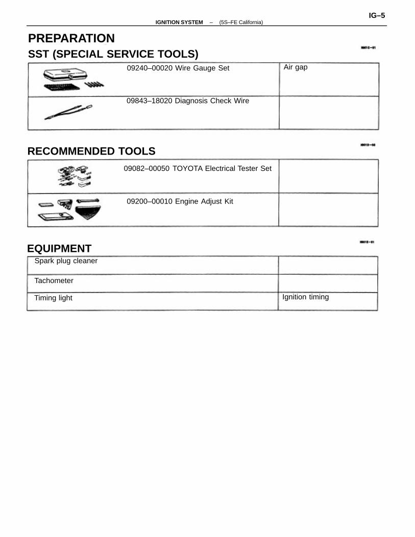
PREPARATIONSST (SPECIAL SERVICE TOOLS)
RECOMMENDED TOOLS09082–00050 TOYOTA Electrical Tester Set
09843–18020 Diagnosis Check Wire
09200–00010 Engine Adjust Kit
09240–00020 Wire Gauge Set
EQUIPMENTSpark plug cleaner
Timing light Ignition timing
Tachometer
Air gap
–IGNITION SYSTEM (5S–FE California)IG–5

ON–VEHICLE INSPECTIONSPARK TEST CHECK THAT SPARK OCCURS
(a) Disconnect the high–tension cord (from the ignitioncoil) from the distributor cap.
(b) Hold the end approx. 12.5 mm (0.50 in.) from the bodyground.
(c) See if spark occurs while engine is being cranked.HINT: To prevent gasoline from being injected frominjectors during this test, crank the engine for no morethan 1–2 seconds at time.If the spark does not occur, perform the test as fol–lows:
CHECK RESISTANCE OF SIGNALGENERATOR (PICKUP COIL)See page ( IG–12)Resistance: Cold HotG1 and G–125–200 �160–235�G 2 and G–125–200�160–235�N E and G–155–250�190–290�
CHECK RESISTANCE OF IGNITION COILSee page IG–10)Resistance: Cold HotPrimary 0.36–0.55 0 0.45–0.65 �
Secondary 9.0–15.4 k � 11.4–18.1 k�
CHECK POWER SUPPLY TO IGNITIONCOIL AND IGNITER1. Turn ignition switch to ON.2. Check that there is battery voltage at
ignition coil positive (+) terminal.
CHECK RESISTANCE OF HIGH–TENSIONCORD (See Page IG–7)Maximum resistance: 25 k � per cord
CHECK AIR GAP OF DISTRIBUTOR(See page IG–11 )Air gap: 0.2–0.5 mm (0.008–0.020 in.)
CHECK CONNECTION OF IGNITION COIL,IGNITER AND DISTRIBUTOR CONNECTOR
CHECK IGT SIGNAL FROM ECM(See page EG–344)
Check wiring between ECM, distributorand igniter, only then try another ECM.
Check wiring between ignition switchto ignition coil and igniter.
Replace the distributor housingassembly.
Replace the distributor housingassembly.
TRY ANOTHER IGNITER
Replace the ignition coil.
Replace the cord(s).
Connect securely.
SPARK TEST
BAD
BAD
BAD
BAD
BAD
BAD
BAD
–IGNITION SYSTEM (5S–FE California)IG–6

4. INSPECT HIGH–TENSION CORD RESISTANCEUsing an ohmmeter, measure the resistance.Maximum resistance: 25 k� per cord .If the resistance is greater than maximum, check theterminals. If necessary, replace the high–tensioncord.
1. DISCONNECT HIGH–TENSION CORDS FROM SPARK PLUGS
Disconnect the high–tension cords at the rubber boot. Do not pull on the high–tension cords. NOTICE: Pulling on or bending the cords may damage the conductor inside.
6. RECONNECT HIGH–TENSION CORDS TODISTRIBUTOR CAP
6. RECONNECT HIGH–TENSION CORD TO IGNITIONCOIL7. RECONNECT HIGH–TENSION CORDS TO SPARKPLUGS
2. DISCONNECT HIGH–TENSION CORD FROMIGNITION COIL
3. DISCONNECT HIGH–TENSION CORDS FROM DISTRIBUTOR CAP
HIGH–TENSION CORDS INSPECTION
–IGNITION SYSTEM (5S–FE California)IG–7
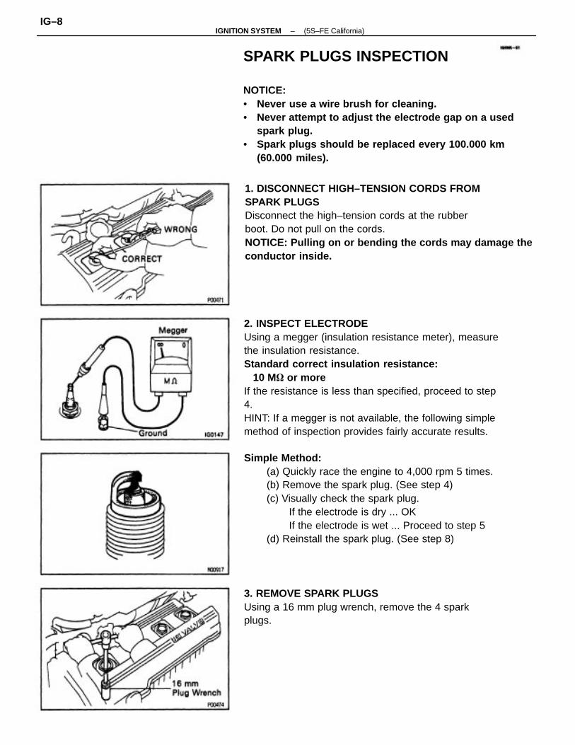
2. INSPECT ELECTRODEUsing a megger (insulation resistance meter), measurethe insulation resistance.Standard correct insulation resistance: 10 M� or moreIf the resistance is less than specified, proceed to step4.HINT: If a megger is not available, the following simplemethod of inspection provides fairly accurate results.
SPARK PLUGS INSPECTION
NOTICE:• Never use a wire brush for cleaning.• Never attempt to adjust the electrode gap on a used
spark plug.• Spark plugs should be replaced every 100.000 km
(60.000 miles).
Simple Method:(a) Quickly race the engine to 4,000 rpm 5 times.(b) Remove the spark plug. (See step 4)(c) Visually check the spark plug.
If the electrode is dry ... OKIf the electrode is wet ... Proceed to step 5
(d) Reinstall the spark plug. (See step 8)
1. DISCONNECT HIGH–TENSION CORDS FROMSPARK PLUGSDisconnect the high–tension cords at the rubberboot. Do not pull on the cords.NOTICE: Pulling on or bending the cords may damage theconductor inside.
3. REMOVE SPARK PLUGSUsing a 16 mm plug wrench, remove the 4 sparkplugs.
–IGNITION SYSTEM (5S–FE California)IG–8

5. INSPECT ELECTRODE GAPMaximum electrode gap for used spark plug: 1.3 mm (0.051 In.)If the gap is greater than maximum, replace the sparkplug.Correct electrode gap for new spark plug: 1.1 m m (0.043 in.)NOTICE: if adjusting the gap of a new spark plug, bendonly the base of the ground electrode. Do not touch thetip. Never attempt to adjust the gap on the used plug.6. CLEAN SPARK PLUGSIf the electrode has traces of wet carbon, allow it todry and then clean with a spark plug cleaner.Air pressure: Below 588 kPa (6 kgf/cm2, 85 psi)Duration: 20 seconds or lessHINT: If there are traces of oil, remove it with gasolinebefore using the spark plug cleaner.
4. VISUALLY INSPECT SPARK PLUGSCheck the spark plug for thread damage and insulatordamage.If abnormal, replace the spark plug.Recommended spark plug: PK20R11 for ND BKR6EP11 for NGK
7. REINSTALL SPARK PLUGSUsing a 16 mm plug wrench, install the 4 spark plugs.Torque: 18 N–m (180 k9f–cm. 13 ft–lbf)
8. RECONNECT HIGH–TENSION CORDS T4 SPARKPLUGS
–IGNITION SYSTEM (5S–FE California)IG–9

3. INSPECT PRIMARY COIL RESISTANCEUsing an ohmmeter, measure the resistance betweenthe positive (+) and negative (–) terminals.Primary coil resistance (Cold): 0.36–0.55�Primary coil resistance (Hot): 0.45–O.65�If the resistance is not as specified, replace the igni–tion coil.
4. INSPECT SECONDARY COIL RESISTANCEUsing an ohmmeter, measure the resistance betweenthe positive (+) and high–tension terminals.Secondary coil resistance (Cold): 9.0–15.4 k�Secondary coil resistance (Hot): 11.4–18.1 k�If the resistance is not as specified, replace the igni–tion coil.
IGNITION COIL INSPECTIONNOTICE: ’Cold’ and ’Hot’ in the following sentences ex–press the temperature of the coils themselves. ’Cold’ isfrom–10 �C (14�F) to 50�C (122�F) and ’Hot’ is from60�C
(122” F) to 100 �C (212�F).1. DISCONNECT IGNITION COIL CONNECTOR2. DISCONNECT HIGH–TENSION CORD FROMIGNITION COIL
6. RECONNECT HIGH–TENSION CORD TO IGNITIONCOIL6. RECONNECT IGNITION COIL CONNECTOR
–IGNITION SYSTEM (5S–FE California)IG–10
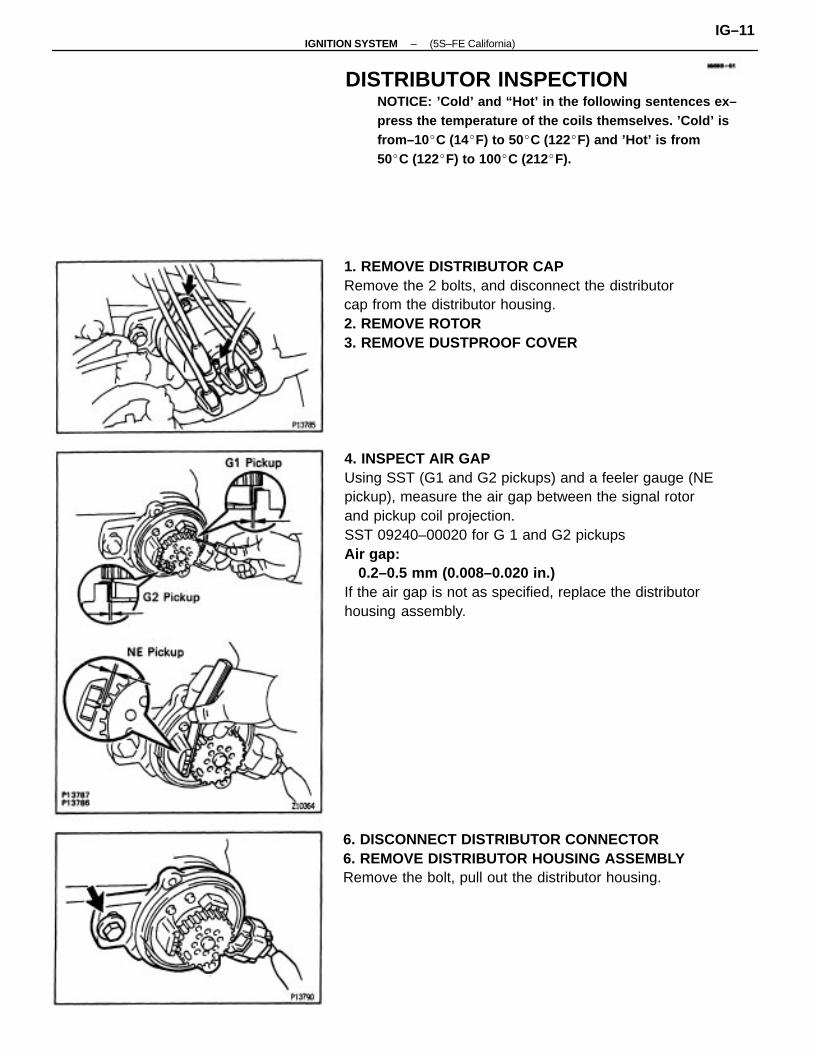
4. INSPECT AIR GAPUsing SST (G1 and G2 pickups) and a feeler gauge (NEpickup), measure the air gap between the signal rotorand pickup coil projection.SST 09240–00020 for G 1 and G2 pickupsAir gap: 0.2–0.5 mm (0.008–0.020 in.)If the air gap is not as specified, replace the distributorhousing assembly.
DISTRIBUTOR INSPECTIONNOTICE: ’Cold’ and “Hot’ in the following sentences ex–press the temperature of the coils themselves. ’Cold’ isfrom–10 �C (14�F) to 50�C (122�F) and ’Hot’ is from50�C (122�F) to 100�C (212�F).
1. REMOVE DISTRIBUTOR CAPRemove the 2 bolts, and disconnect the distributorcap from the distributor housing.2. REMOVE ROTOR3. REMOVE DUSTPROOF COVER
6. DISCONNECT DISTRIBUTOR CONNECTOR6. REMOVE DISTRIBUTOR HOUSING ASSEMBLYRemove the bolt, pull out the distributor housing.
–IGNITION SYSTEM (5S–FE California)IG–11

7. INSPECT SIGNAL GENERATOR (PICKUP COIL)RESISTANCEUsing an ohmmeter, measure the resistance betweenterminals.Pickup coil resistance (Cold): G1 and GE) 125–200� G2 and G(–) 125–200� NE and G(–) 155–2500Pickup coil resistance (Hot): G 1 and G(–) 160–235� G2 and G(–) 160–235� NE and G(–) 190–290�If the resistance is not as specified, replace the distributorhousing assembly.8. REINSTALL DISTRIBUTOR HOUSING ASSEMBLY (See steps 1 and 2 on pages IG–17 and 18)9. RECONNECT DISTRIBUTOR CONNECTOR10. REINSTALL DUSTPROOF COVER11. REINSTALL ROTOR
12. REINSTALL DISTRIBUTOR CAPInstall a new packing and distributor cap with the 2bolts.13. ADJUST IGNITION TIMING (See page IG–19)
IGNITER INSPECTION(See Spark Test procedure on page IG–6)
–IGNITION SYSTEM (5S–FE California)IG–12

DISTRIBUTOR REMOVAL(See Components for Removal and Installation)1. DISCONNECT NEGATIVE (–) TERMINAL CABLE
FROM BATTERYCAUTION: Work must be started after 90 seconds fromthe time the Ignition switch Is turned to the ’LOCK’position and the negative (–) terminal cable is discon–nacted from the battery.
DISTRIBUTORCOMPONENTS FOR REMOVAL ANDINSTALLATION
2. DISCONNECT ACCELERATOR CABLE FROMTHROTTLE BODY
–IGNITION SYSTEM (5S–FE California)IG–13

6. DISCONNECT HIGH–TENSION CORDS FROM SPARK PLUGS
(a) Disconnect the high–tension cords from the cordclamps.
(b) Disconnect the 4 high–tension cords from the sparkplugs.Disconnect the high–tension cords at the rubberboot. Do not pull on the high–tension cords.
NOTICE: Pulling on or bending the cords may damage theconductor Inside.
7. REMOVE DISTRIBUTOR(a) Remove the hold–down bolt, and pull out the distrib–
utor.(b) Remove the 0–ring from the distributor housing.
3. REMOVE AIR CLEANER CAP, RESONATOR ANDAIR CLEANER HOSE
(a) Disconnect the intake air temperature sensor connec–tor.
(b) Disconnect the air hose from the air cleaner hose.(c) Loosen the air cleaner hose clamp bolt.(d) Disconnect the 4 air cleaner cap clips.(e) Disconnect the air cleaner hose from the throttle
body, and remove the air cleaner cap together withthe resonator and air cleaner hose.
4. DISCONNECT DISTRIBUTOR CONNECTOR5. DISCONNECT NIGH–TENSION CORD FROM IGNITION COIL
–IGNITION SYSTEM (5S–FE California)IG–14

DISTRIBUTOR DISASSEMBLY
(See Components for Disassembly and Assembly)1. REMOVE DISTRIBUTOR CAPRemove the 2 bolts, distributor cap and packing.
COMPONENTS FOR DISASSEMBLY ANDASSEMBLY
2.REMOVE ROTORRemove the 2 screws and rotor.
–IGNITION SYSTEM (5S–FE California)IG–15

DISTRIBUTOR INSPECTION
INSPECT SHAFTTurn the shaft and check that it is not rough or worn.If it feels rough or worn, replace the distributor hous–ing assembly.
DISTRIBUTOR ASSEMBLY
(See Components for Disassembly and Assembly)1. INSTALL DUST PROOF COVER(a) Install the dust proof cover.
3. REMOVE DUST PROOF COVER(a) Remove the dust proof seal.
(b) Remove the dust proof cover.
(b) Install the dust proof.seal.
–IGNITION SYSTEM (5S–FE California)IG–16
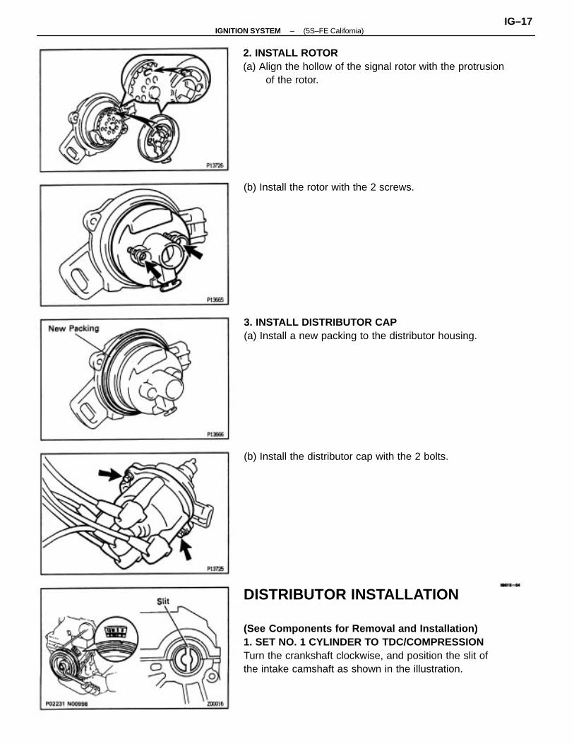
DISTRIBUTOR INSTALLATION
(See Components for Removal and Installation)1. SET NO. 1 CYLINDER TO TDC/COMPRESSIONTurn the crankshaft clockwise, and position the slit ofthe intake camshaft as shown in the illustration.
2. INSTALL ROTOR(a) Align the hollow of the signal rotor with the protrusion
of the rotor.
3. INSTALL DISTRIBUTOR CAP(a) Install a new packing to the distributor housing.
(b) Install the distributor cap with the 2 bolts.
(b) Install the rotor with the 2 screws.
–IGNITION SYSTEM (5S–FE California)IG–17

6. INSTALL AIR CLEANER CAP, RESONATOR ANDAIR CLEANER HOSE(a) Connect the air cleaner hose to the throttle body.(b) Install the air cleaner cap together with the resonator
and air cleaner hose.(c) Connect the air hose to the air cleaner hose.(d) Connect the intake air temperature sensor connector.
3. CONNECT HIGH–TENSION CORDS TO SPARKPLUGS
Firing order: 1–3–4–24. CONNECT HIGH–TENSION CORD TO IGNITIONCOIL5. CONNECT DISTRIBUTOR CONNECTOR
(c) Align the cutout of the coupling with the line of thehousing.
(d) Insert the distributor, aligning the center of the flangewith that of bolt hole on the cylinder head.
(e) Lightly tighten the hold–down bolt.(f) Connect the high–tension cords to the clamp on the
cylinder head cover.
2. INSTALL DISTRIBUTOR(a) Install a new O–ring to the housing.(b) Apply a light coat of engine oil on the 0–ring.
–IGNITION SYSTEM (5S–FE California)IG–18

10. CONNECT TACHOMETER AND TIMING LIGHT TOENGINEConnect the test probe of a tachometer to terminal IGE) of thedata link connector 1.NOTICE:• NEVER allow the tachometer terminal to touch
ground as It could result In damage to the igniterand/or ignition coil.
• As some tachometers are not compatible with thisignition system, we recommend that you confirmthe compatibility of yours before use. .
7. CONNECT AND ADJUST ACCELERATOR CABLE8. CONNECT NEGATIVE (–) TERMINAL CABLE TOBATTERY9. WARM UP ENGINEAllow the engine to warm up to normal operatingtemperature.
11. ADJUST IGNITION TIMING(a) Using SST, connect terminals TE1 and E1 of the data
link connector 1.SST 09843–18020
HINT: After engine speed is kept at 1,000–1,300 rpm for 5 seconds, check that it returns to idle speed.
(b) Using a timing light, check the ignition timing.Ignition timing:10� BTDC 0 idle
(Transmission in neutral position)
–IGNITION SYSTEM (5S–FE California)IG–19

12. FURTHER CHECK IGNITION TIMING Ignition timing: 0–10� BTDC 0 idle (Transmission in neutral position)HINT: The timing mark moves in a range between 0�and 10�.
(c) Loosen the hold–down bolt, and adjust by turningthe distributor.
(d) Tighten the hold–down bolt, and recheck the ignitiontiming.
Torque: 19 N–m (195 kgf–cm, 14 ft–lbf)
13. DISCONNECT TACHOMETER AND TIMING LIGHTFROM ENGINE
(e) Remove the SST.SST 09843–18020
–IGNITION SYSTEM (5S–FE California)IG–20

SERVICE SPECIFICATIONSSERVICE DATA
TORQUE SPECIFICATIONS
w/ Terminals TE1 and E1 connected of DLC1
Air gapPickup coil resistance
Spark plug x Cylinder head
Distributor x Cylinder head
Recommended spark plug
High–tensioncord
Secondary coil resistance
Primary coil resistanceCorrect electrode gap
Firing order
Ignition timing
Part tightened
Ignition coil
Spark plug
Distributor
Resistance
–IGNITION SYSTEM (5S–FE California)IG–21
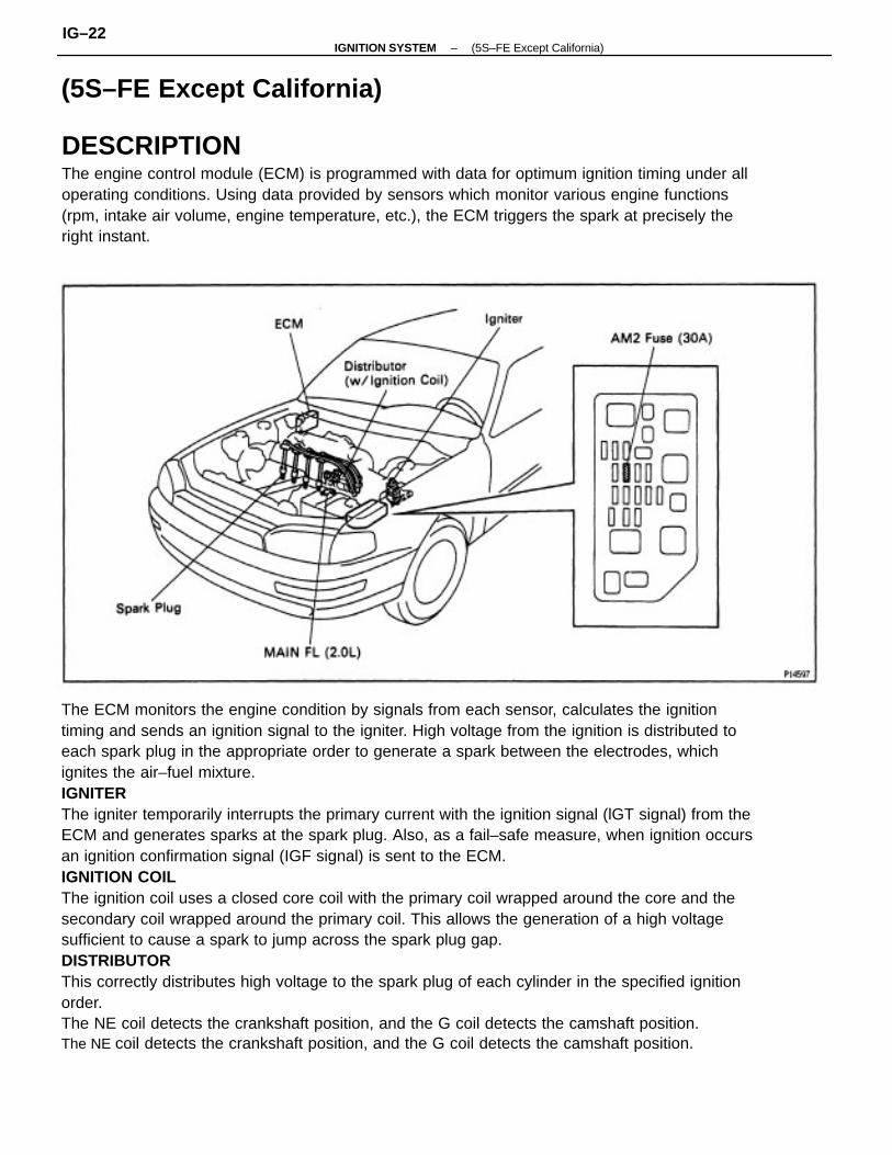
The ECM monitors the engine condition by signals from each sensor, calculates the ignitiontiming and sends an ignition signal to the igniter. High voltage from the ignition is distributed toeach spark plug in the appropriate order to generate a spark between the electrodes, whichignites the air–fuel mixture.IGNITERThe igniter temporarily interrupts the primary current with the ignition signal (lGT signal) from theECM and generates sparks at the spark plug. Also, as a fail–safe measure, when ignition occursan ignition confirmation signal (IGF signal) is sent to the ECM.IGNITION COILThe ignition coil uses a closed core coil with the primary coil wrapped around the core and thesecondary coil wrapped around the primary coil. This allows the generation of a high voltagesufficient to cause a spark to jump across the spark plug gap.DISTRIBUTORThis correctly distributes high voltage to the spark plug of each cylinder in the specified ignitionorder.The NE coil detects the crankshaft position, and the G coil detects the camshaft position.The NE coil detects the crankshaft position, and the G coil detects the camshaft position.
DESCRIPTIONThe engine control module (ECM) is programmed with data for optimum ignition timing under alloperating conditions. Using data provided by sensors which monitor various engine functions(rpm, intake air volume, engine temperature, etc.), the ECM triggers the spark at precisely theright instant.
(5S–FE Except California)
–IGNITION SYSTEM (5S–FE Except California)IG–22
3. As some tachometers are not compatible with thisignition system, we recommend that you confirmthe compatibility of yours before use.
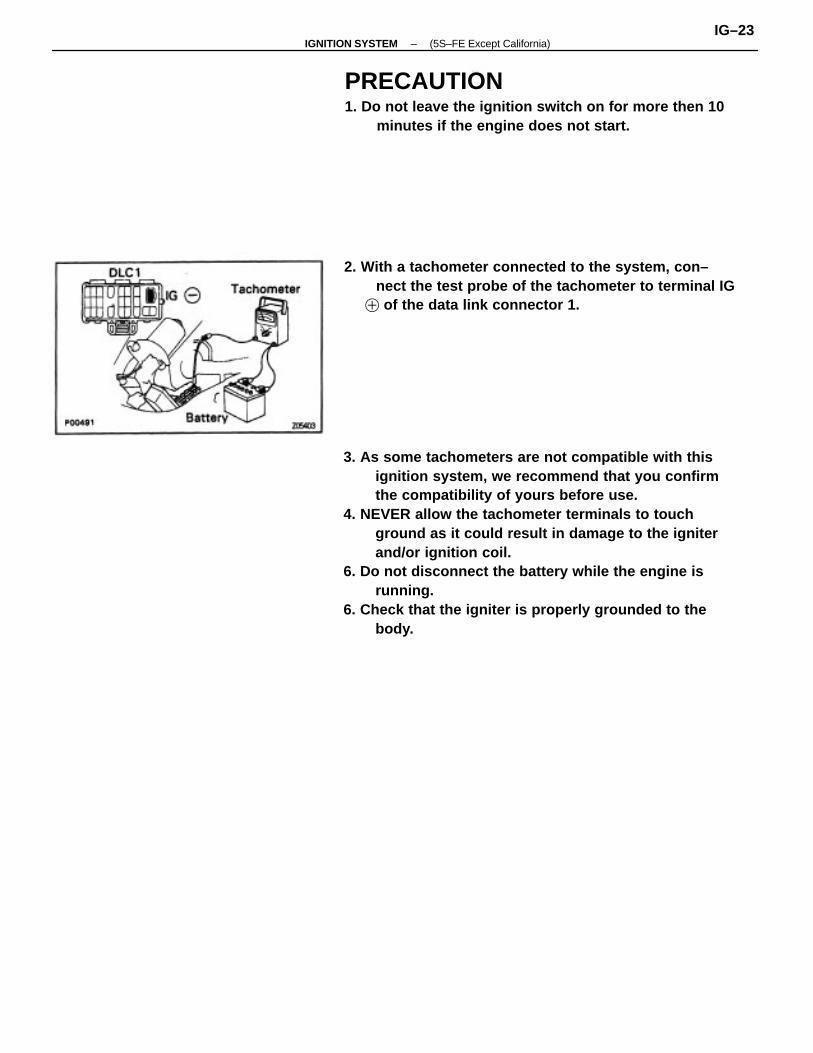
4. NEVER allow the tachometer terminals to touchground as it could result in damage to the igniterand/or ignition coil.
6. Do not disconnect the battery while the engine isrunning.
6. Check that the igniter is properly grounded to thebody.
PRECAUTION1. Do not leave the ignition switch on for more then 10
minutes if the engine does not start.
2. With a tachometer connected to the system, con–nect the test probe of the tachometer to terminal IG
� of the data link connector 1.
–IGNITION SYSTEM (5S–FE Except California)IG–23

OPERATIONTo maintain the most appropriate ignition timing, the ECM sends a control signal so that theigniter sends current to the ignition coil and the spark plugs produce a spark.
SYSTEM CIRCUIT
–IGNITION SYSTEM (5S–FE Except California)IG–24

PREPARATIONSST (SPECIAL SERVICE TOOLS)
SSM (SPECIAL SERVICE MATERIALS)
RECOMMENDED TOOLS09082–00050 TOYOTA Electrical Tester Set
08826–00080 Seal packing orequivalent
Megger insulation resistance meter
09843–18020 Diagnosis CheckWire
09200–00010 Engine Adjust Kit
Insulation resistance meter
EQUIPMENT
Spark plug cleaner
Timing light Ignition timing
Tachometer
Ignition coil
–IGNITION SYSTEM (5S–FE Except California)IG–25

ON–VEHICLE INSPECTIONSPARK TESTCHECK THAT SPARK OCCURS
(a) Disconnect the high–tension cords from the sparkplugs. (See page IG–28)
(b) Remove the spark plugs. (See page IG–28)(c) Install the spark plugs to the each high–tension cord.(d) Ground the spark plug.(e) Check if spark occurs while engine is being cranked.
HINT: To prevent gasoline from being injected frominjectors during this test, crank the engine for no morethan 1–2 seconds at a time. If the spark does notoccur, perform the test as follows:
CHECK RESISTANCE OF SIGNALGENERATOR (PICKUP COIL)(See page IG–31)Resistance: Cold HotG (+) and IG (–) 185–275 � 240–325�N E (+) and NE (–) 370–550� 475–650 �
CHECK RESISTANCE OF IGNITION COIL(See page IG–30)Resistance: Cold HotPrimary 0.36–0.55 � 0.45–0.65 �Secondary 9.0–15.4 k � 11.4–18.1 k�
CHECK POWER SUPPLY TO IGNITIONCOIL1. Turn ignition switch ON.2. Check that there is battery voltage atignition coil positive (+) terminal.
CHECK AIR GAP OF DISTRIBUTOR(See page IG–30)Air gap: 0.2–0.4 mm (0.008–0.016 in.)
CHECK RESISTANCE OF HIGH–TENSIONCORD (See page IG–27)Maximum resistance: 25 k � per cord
CHECK CONNECTION OF DISTRIBUTORCONNECTORS
CHECK IGT SIGNAL FROM ECM(See page EG–344)
Check wiring between ECM, distributorand igniter, and then try another ECM.
Check wiring between ignition switchand ignition coil.
Replace the distributor housingassembly.
Replace distributor housing assembly.
TRY ANOTHER IGNITER
Replace the ignition coil.
Replace the cord (s) .
Connect securely.
SPARK TEST
BAD
BAD
BAD
BAD
BAD
BAD
BAD
–IGNITION SYSTEM (5S–FE Except California)IG–26

HIGH–TENSION CORDS INSPECTION1. DISCONNECT HIGH–TENSION CORDS FROM
SPARK PLUGS Disconnect the high–tension cords at the rubber boot.DO NOT pull on the cords.NOTICE: Pulling on or bending the cords may damage theconductor inside.
3. INSPECT HIGH–TENSION CORD RESISTANCEUsing an ohmmeter, measure the resistance. Maximum resistance: 25 k� per cordIf the resistance is greater than maximum, check theterminals. If necessary, replace the high–tensioncord.
4. RECONNECT HIGH–TENSION CORDS TODISTRIBUTOR CAP5. RECONNECT HIGH–TENSION CORDS TO SPARKPLUGS .
2. DISCONNECT HIGH–TENSION CORDS FROMDISTRIBUTOR CAP
–IGNITION SYSTEM (5S–FE Except California)IG–27
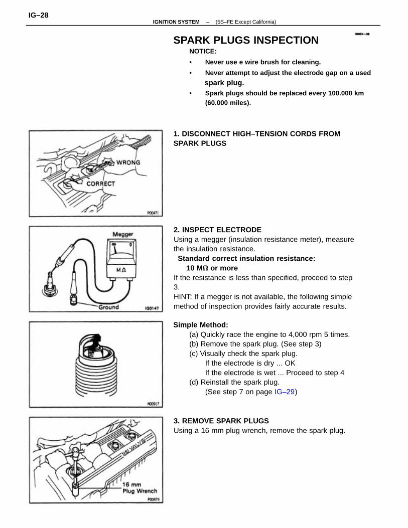
2. INSPECT ELECTRODEUsing a megger (insulation resistance meter), measurethe insulation resistance. Standard correct insulation resistance: 10 M� or moreIf the resistance is less than specified, proceed to step3.HINT: If a megger is not available, the following simplemethod of inspection provides fairly accurate results.
SPARK PLUGS INSPECTIONNOTICE:
• Never use e wire brush for cleaning.
• Never attempt to adjust the electrode gap on a used
spark plug.• Spark plugs should be replaced every 100.000 km
(60.000 miles).
Simple Method:(a) Quickly race the engine to 4,000 rpm 5 times.(b) Remove the spark plug. (See step 3)(c) Visually check the spark plug.
If the electrode is dry ... OKIf the electrode is wet ... Proceed to step 4
(d) Reinstall the spark plug.(See step 7 on page IG–29)
3. REMOVE SPARK PLUGSUsing a 16 mm plug wrench, remove the spark plug.
1. DISCONNECT HIGH–TENSION CORDS FROMSPARK PLUGS
–IGNITION SYSTEM (5S–FE Except California)IG–28

5. INSPECT ELECTRODE GAP Maximum electrode gap: 1.3 mm (0.051 in.)If the gap is greater than maximum, replace the sparkplug.Correct electrode gap of new spark plug: 1.1 mm (0.043 in.)
NOTICE: If adjusting the gap of a new spark plug, bendonly the base of the ground electrode. Do not touch thetip. Never attempt to adjust the gap on the used plug.
6. CLEAN SPARK PLUGSIf the electrode has traces of wet carbon, allow it todry and then clean with a spark plug cleaner. Air pressure: Below 588 kPa (6 kgf/cm2, 85 psi) Duration: 20 seconds or lessHINT: If there are traces of oil, remove it with gasolinebefore using the spark plug cleaner.
4. VISUALLY INSPECT SPARK PLUGSCheck the spark plug for thread damage and insulatordamage.If abnormal, replace the spark plug.Recommended spark plug: PK20R 11 for N D BKR6EP11 for NGK
7. INSTALL SPARK PLUGSUsing a 16 mm plug wrench, install the spark plug.Torque: 18 N–m (180 kgf–cm, 13 ft–lbf)8. RECONNECT HIGH–TENSION CORDS TO SPARKPLUGS
–IGNITION SYSTEM (5S–FE Except California)IG–29
DISTRIBUTOR INSPECTION
NOTICE: ’Cold’ and ’Hot’ in the following sentences ex–press the temperature of the coils themselves. ’Cold’ isfrom–10 �C (14�F) to 50�C (122�F) and ’Hot’ is from50�C (122�F) to 100�C (212�F).
1. DISCONNECT DISTRIBUTOR CONNECTORS2. REMOVE DISTRIBUTOR CAP3. REMOVE ROTOR4. REMOVE IGNITION COIL DUST COVER
Ignition Coil
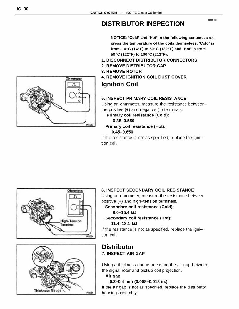
5. INSPECT PRIMARY COIL RESISTANCEUsing an ohmmeter, measure the resistance between–the positive (+) and negative (–) terminals. Primary coil resistance (Cold): 0.38–0.550 Primary coil resistance (Hot): 0.45–0.650If the resistance is not as specified, replace the igni–tion coil.
Distributor7. INSPECT AIR GAP
Using a thickness gauge, measure the air gap betweenthe signal rotor and pickup coil projection. Air gap: 0.2–0.4 mm (0.008–0.018 in.)If the air gap is not as specified, replace the distributorhousing assembly.
6. INSPECT SECONDARY COIL RESISTANCEUsing an ohmmeter, measure the resistance betweenpositive (+) and high–tension terminals. Secondary coil resistance (Cold): 9.0–15.4 k� Secondary coil resistance (Hot): 11.4–18.1 k�If the resistance is not as specified, replace the igni–tion coil.
–IGNITION SYSTEM (5S–FE Except California)IG–30

8. INSPECT SIGNAL GENERATOR (PICKUP COIL)RESISTANCE
Using an ohmmeter, measure the resistance betweenthe terminals (G� and G�, NE� and NE�).Pickup coil resistance (Cold): G� and G�
185–2750 NE� and NE�
370–5500Pickup coil resistance (Hot): G� and G�
240–3250 NE� and NE�
475–6500If the resestance is not as specified, replace the dis–tributor housing assmebly.
9. REINSTALL IGNITION COIL DUST COVER10. REINSTALL ROTOR11. REINSTALL DISTRIBUTOR CAP12. RECONNECT DISTRIBUTOR CONNECTORS
IGNITER INSPECTION(See Spark Test procedure on page IG–26)
–IGNITION SYSTEM (5S–FE Except California)IG–31
DISTRIBUTOR REMOVAL
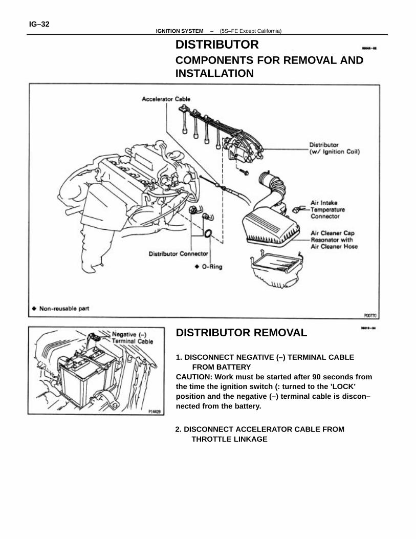
1. DISCONNECT NEGATIVE (–) TERMINAL CABLEFROM BATTERY
CAUTION: Work must be started after 90 seconds fromthe time the ignition switch (: turned to the ’LOCK’position and the negative (–) terminal cable is discon–nected from the battery.
DISTRIBUTORCOMPONENTS FOR REMOVAL ANDINSTALLATION
2. DISCONNECT ACCELERATOR CABLE FROMTHROTTLE LINKAGE
–IGNITION SYSTEM (5S–FE Except California)IG–32

3. REMOVE AIR CLEANER CAP, RESONATOR ANDAIR CLEANER HOSE(a) Disconnect the intake air temperature sensor connec– tor.(b) Loosen the air cleaner hose clamp bolt.(c) Disconnect the 4 air cleaner cap clips.(d) Disconnect the air cleaner hose from the throttle body, and remove the air cleaner cap together with the resonator and air cleaner hose.4. DISCONNECT DISTRIBUTOR CONNECTORS5. DISCONNECT HIGH–TENSION CORDS FROMSPARK PLUGS(a) Disconnect the 4 high–tension cords from the spark plugs.(b) Disconnect the high–tension cords from the clamp on the cylinder head cover.
6. REMOVE DISTRIBUTOR(a) Remove the 2 hold–down bolts, and pull out the
distributor.(b) Remove the 0–ring from the distributor housing.
–IGNITION SYSTEM (5S–FE Except California)IG–33

DISTRIBUTOR DISASSEMBLY
1. REMOVE DISTRIBUTOR CAP WITHOUT DISCONNECTINGHIGH–TENSION CORDS
2. REMOVE ROTOR3. REMOVE IGNITION COIL DUST COVER
4. REMOVE IGNITION COIL(a) Remove the 2 nuts, and disconnect the 3 wires from
the ignition coil terminals.
COMPONENTS FOR DISASSEMBLYAND ASSEMBLY
–IGNITION SYSTEM (5S–FE Except California)IG–34

DISTRIBUTOR INSPECTION INSPECT SHAFTTurn the shaft and check that it is not rough or worn.If it feels rough or worn, replace the distributor hous–ing assembly.
DISTRIBUTOR ASSEMBLY(See Components for Disassembly and Assembly)1. INSTALL CONDENSERInstall the condenser with the screw.
B. REMOVE DISTRIBUTOR WIRERemove the distributor wire from the distributor hous–ing.
6. REMOVE CONDENSERRemove the screw and condenser.
(b) Remove the 4 screws and ignition coil.
–IGNITION SYSTEM (5S–FE Except California)IG–35
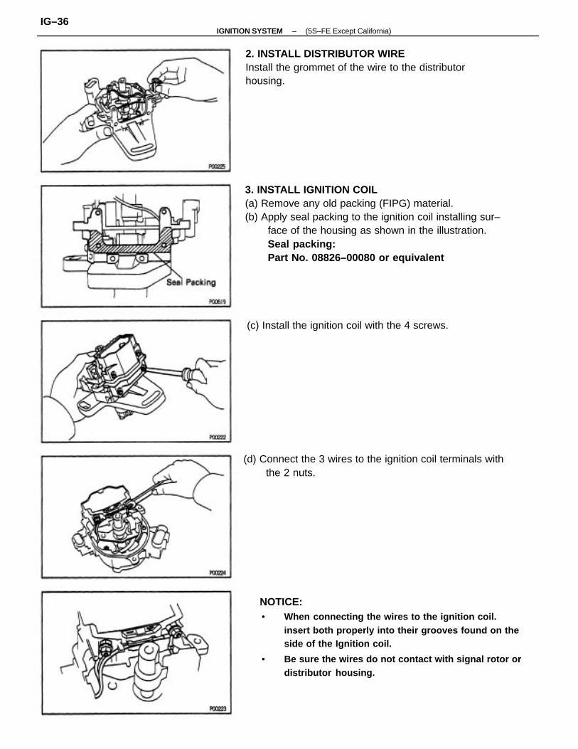
3. INSTALL IGNITION COIL(a) Remove any old packing (FIPG) material.(b) Apply seal packing to the ignition coil installing sur–
face of the housing as shown in the illustration.Seal packing:Part No. 08826–00080 or equivalent
NOTICE:• When connecting the wires to the ignition coil.
insert both properly into their grooves found on theside of the Ignition coil.
• Be sure the wires do not contact with signal rotor ordistributor housing.
2. INSTALL DISTRIBUTOR WIREInstall the grommet of the wire to the distributorhousing.
(d) Connect the 3 wires to the ignition coil terminals withthe 2 nuts.
(c) Install the ignition coil with the 4 screws.
–IGNITION SYSTEM (5S–FE Except California)IG–36

DISTRIBUTOR INSTALLATION
(See Components for Disassembly and Assembly)1. SET NO. 1 CYLINDER TO TDC/COMPRESSIONTurn the crankshaft clockwise, and position the slit ofthe intake camshaft as shown in the illustration.
(d) Insert the distributor, aligning the center of the flangewith that of bolt hole on the cylinder head.
(e) Lightly tighten the 2 hold–down bolts.(f) Connect the high–tension cords to the clamp on the
cylinder head cover. .
4. INSTALL IGNITION COIL DUST COVER5. INSTALL ROTOR6. INSTALL DISTRIBUTOR CAP AND HIGH–TENSIONCORDS
2. INSTALL DISTRIBUTOR(a) Install a new O–ring to the housing.(b) Apply a light coat of engine oil on the 0–ring.
(c) Align the cutout of the coupling with the line of thehousing.
–IGNITION SYSTEM (5S–FE Except California)IG–37
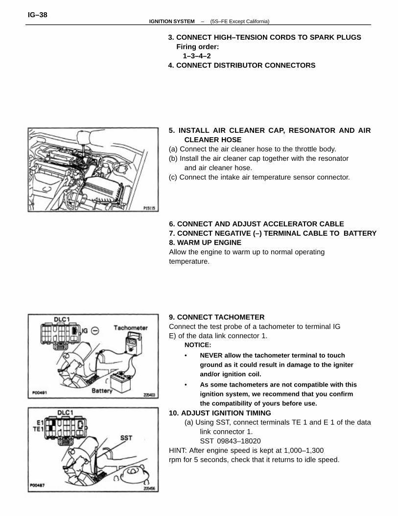
9. CONNECT TACHOMETERConnect the test probe of a tachometer to terminal IGE) of the data link connector 1.
NOTICE:
• NEVER allow the tachometer terminal to touchground as it could result in damage to the igniterand/or ignition coil.
• As some tachometers are not compatible with thisignition system, we recommend that you confirmthe compatibility of yours before use.
10. ADJUST IGNITION TIMING(a) Using SST, connect terminals TE 1 and E 1 of the data
link connector 1.SST 09843–18020
HINT: After engine speed is kept at 1,000–1,300rpm for 5 seconds, check that it returns to idle speed.
5. INSTALL AIR CLEANER CAP, RESONATOR AND AIRCLEANER HOSE
(a) Connect the air cleaner hose to the throttle body.(b) Install the air cleaner cap together with the resonator
and air cleaner hose.(c) Connect the intake air temperature sensor connector.
6. CONNECT AND ADJUST ACCELERATOR CABLE7. CONNECT NEGATIVE (–) TERMINAL CABLE TO BATTERY8. WARM UP ENGINEAllow the engine to warm up to normal operatingtemperature.
3. CONNECT HIGH–TENSION CORDS TO SPARK PLUGS Firing order: 1–3–4–24. CONNECT DISTRIBUTOR CONNECTORS
–IGNITION SYSTEM (5S–FE Except California)IG–38

11. FURTHER CHECK IGNITION TIMING Ignition timing: 0–10� BTDC 0 idle(Transmission In neutral position)HINT: The timing mark moves in a range between 0�and 10�.
(c) Loosen the 2 hold–down bolts, and adjust by turningthe distributor.
(d) Tighten the hold–down bolts, and recheck the igni–tion timing.
Torque: 19 N–m (195 kgf–cm, 14 ft–lbf)
(b) Using a timing light, check the ignition timing.Ignition timing: 10� BTDC 0 Idle
(Transmission In neutral position)
12. DISCONNECT TACHOMETER AND TIMING LIGHTFROM ENGINE
(e) Remove the SST.SST 09843–18020
–IGNITION SYSTEM (5S–FE Except California)IG–39

SERVICE SPECIFICATIONSSERVICE DATA
TORQUE SPECIFICATIONS
w/ Terminals TE1 end E1 connected of DLC1
Air gapPickup coil resistance
Spark plug x Cylinder heed
Recommended spark plug
Distributor x Cylinder head
High–tensioncord
Secondary coil resistance
Primary coil resistance
Correct electrode gap
Ignition timing
Part tightened
Ignition coil
Firing order
Spark plug
Distributor
Resistance
–IGNITION SYSTEM (5S–FE Except California)IG–40

The ECM monitors the engine condition by signals from each sensor, calculates the ignitiontiming and sends an ignition signal to the igniter. High voltage from the ignition is distributed toeach spark plug in the appropriate order to generate a spark between the electrodes, whichignites the air–fuel mixture.IGNITERThe igniter interrupts the primary current with the ignition signal (lGT signal) from the ECM andgenerates sparks at the spark plug. Also, as a fail–safe measure, when ignition occurs an ignitionconfirmation signal (lGF signal) is sent to the ECM.IGNITION COILSThe ignition coil uses a closed core coil with the primary coil wrapped around the core and thesecondary coil wrapped around the primary coil. This allows the generation of a high voltagesufficient to cause a spark to jump across the spark plug gap.CAMSHAFT POSITION SENSORThe camshaft position sensor detect the camshaft position.CRANKSHAFT POSITION SENSORThe crankshaft position sensor detect the crankshaft position.
DESCRIPTIONThe engine control module (ECM) is programmed with data for optimum ignition timing under alloperating conditions. Using data provided by sensors which monitor various engine functions(RPM, intake air volume, engine temperature, etc.), the ECM triggers the spark at precisely theright instant.
(1 MZ–FE)
–IGNITION SYSTEM (1MZ–FE)IG–41

4. As some tachometers are not compatible with thisignition system, we recommend that you confirm
the compatibility of your unit before use.5. Never allow the tachometer terminals to touch
ground as it could result in damage to the igniter and/or ignition coil.6. Do not disconnect the battery while the engine is
running.7. Check that the igniter is properly grounded to the
body.
PRECAUTION1. Do not leave the ignition switch on for more than 10
minutes if the engine does not start.
3. With a timing tight connected to the system, con–nect the timing light pickup clip to the green leadwire for the No.4 ignition coil.
2. With a tachometer connected to the system, con–nect the tester probe of the tachometer to terminal
IG� of the DLC 1.
–IGNITION SYSTEM (1MZ–FE)IG–42

OPERATIONTo maintain the most appropriate ignition timing, the ECM sends a control signal so that theigniter is pass the current to the ignition coils and the spark plugs produce a spark.
SYSTEM CIRCUIT
–IGNITION SYSTEM (1MZ–FE)IG–43
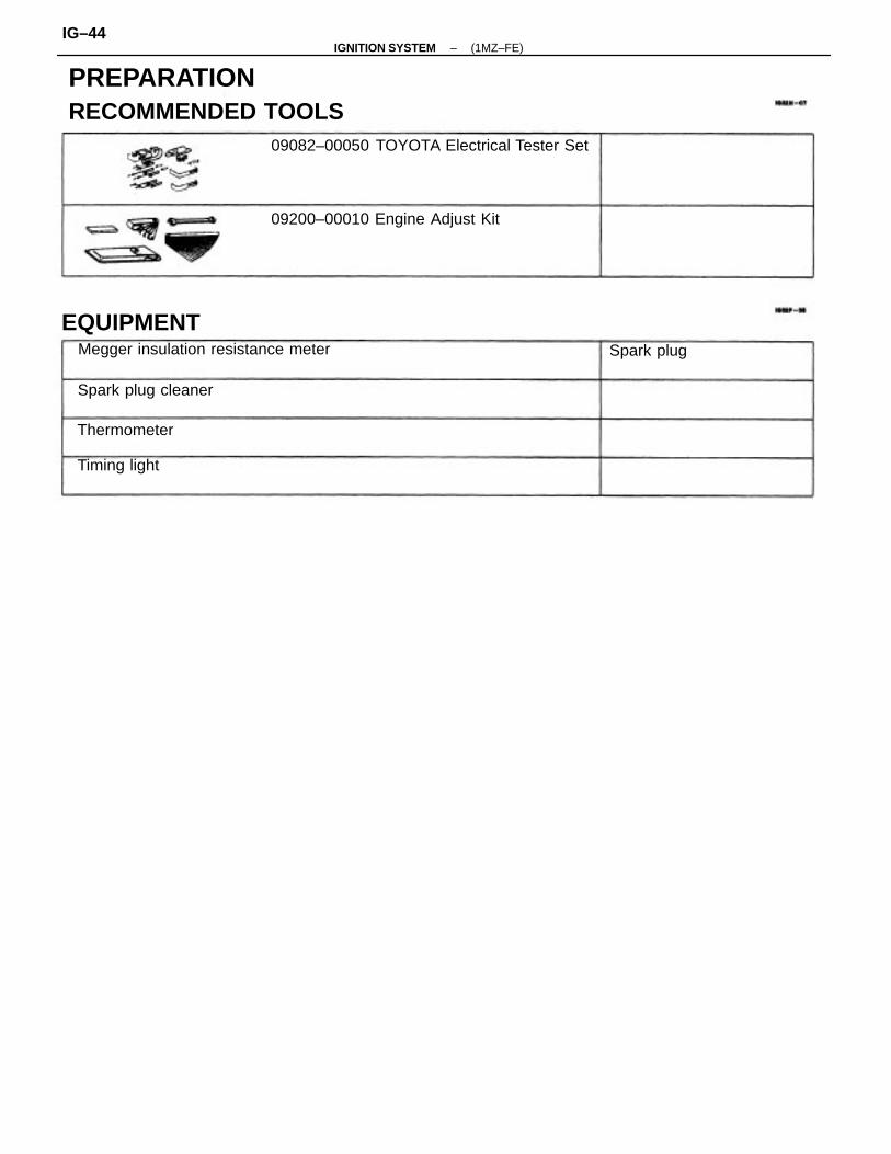
PREPARATIONRECOMMENDED TOOLS
09082–00050 TOYOTA Electrical Tester Set
Megger insulation resistance meter
09200–00010 Engine Adjust Kit
EQUIPMENT
Spark plug cleaner
Thermometer
Timing light
Spark plug
–IGNITION SYSTEM (1MZ–FE)IG–44

ON–VEHICLE INSPECTIONSPARK TEST CHECK THAT SPARK OCCURS(a) Remove the ignition coil.
(See steps 1 to 3 on page IG–50)(b) Remove the spark plug.
(See step 3 on page IG–47)(c) Install the spark plug to the ignition coil, and connect
the ignition coil connecter.(d) Ground the spark plug.(e) Check if spark occurs while engine is being cranked.HINT: To prevent gasoline from being injected frominjectors during this test, crank the engine for no morethan 1–2 seconds at time.If the spark does not occur, perform the test as fol–lows:
CHECK RESISTANCE OF CRANKSHAFT POSITIONSENSOR(See page IG–54)Resistance:Cold : 1,630–2,7400, Hot : 2,065–3,2250
CHECK RESISTANCE OF CAMSHAFT POSITION SENSOR(See page IG–49)Resistance:Cold : 835–1,4000, Hot : 1,060–1,6450
CHECK POWER SUPPLY TO IGNITION COILAND IGNITER1. Turn ignitioin switch ON.2. Check that there is battery voltage at
Ignition coil positive (+) terminal.
CHECK RESISTANCE OF IGNITION COIL(See page IG–48)Resistance:Primary Cold : 0.54–0.84II, Hot : 0.68–0.98 n
CHECK CONNECTION OF IGNITION COIL ANDIGNITER
Check wiring between ECM, and igni-ter, and then try another ECM.
Check wiring between ignitionswitchto ignition coil and igniter.
CHECK IGT SIGNAL FROM ECM
(See page EG–550)
Replace the crankshaft position sen-sor.
Replace the camshaft position sen-sor.
Replace the ignition coil.
TRY ANOTHER IGNITER
Connect securely.
SPARK TEST
BAD
BAD
BAD
BAD
BAD
BAD
–IGNITION SYSTEM (1MZ–FE)IG–45

2. INSPECT ELECTRODEUsing a megger (insulation resistance meter), measurethe insulation resistance.Standard correct Insulation resistance: 10 M� or moreIf the resistance is less than specified, proceed to step4.HINT: If a megger is not available, the following simplemethod of inspection provides fairly accurate results.
SPARK PLUGS INSPECTIONNOTICE:
• Never use a wire brush for cleaning.
• Never attempt to adjust the electrode gap on a usedspark plug.
• Spark plugs should be replaced every 100,000 km(60,000 miles).
Simple Method:(a) Quickly race the engine to 4,000 rpm 5 times.(b) Remove the spark plug. (See step 3)(c) Visually check the spark plug.
If the electrode is dry ... OKIf the electrode is wet ... Proceed to step 4
(d) Reinstall the spark plug. (See step 7)
(f) Reinstall the spark plug.(See step 7 on page IG–47)
(g) Reinstall the ignition coil.(See steps 1 to 3 on page IG–51)
1. REMOVE IGNITION COILS(See steps 1 to 3 on page IG–b0)
–IGNITION SYSTEM (1MZ–FE)IG–46
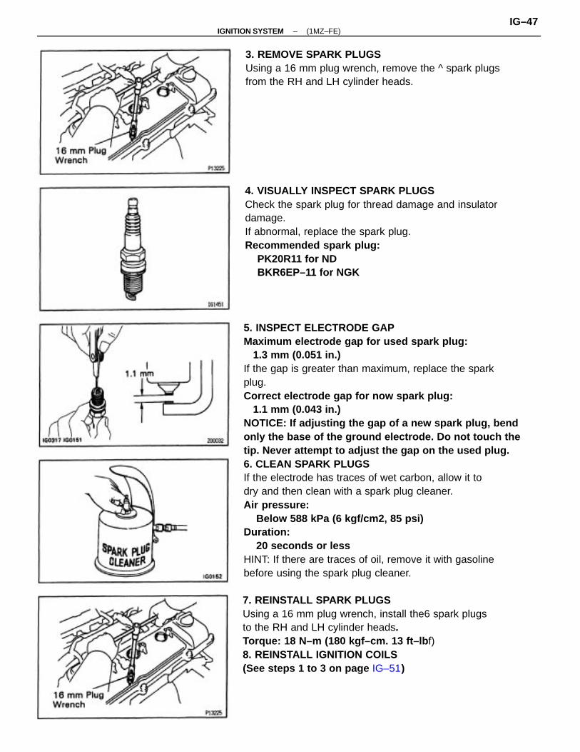
5. INSPECT ELECTRODE GAPMaximum electrode gap for used spark plug: 1.3 mm (0.051 in.)If the gap is greater than maximum, replace the sparkplug.Correct electrode gap for now spark plug: 1.1 mm (0.043 in.)NOTICE: If adjusting the gap of a new spark plug, bendonly the base of the ground electrode. Do not touch thetip. Never attempt to adjust the gap on the used plug.6. CLEAN SPARK PLUGSIf the electrode has traces of wet carbon, allow it todry and then clean with a spark plug cleaner.Air pressure: Below 588 kPa (6 kgf/cm2, 85 psi)Duration: 20 seconds or lessHINT: If there are traces of oil, remove it with gasolinebefore using the spark plug cleaner.
4. VISUALLY INSPECT SPARK PLUGSCheck the spark plug for thread damage and insulatordamage.If abnormal, replace the spark plug.Recommended spark plug: PK20R11 for ND BKR6EP–11 for NGK
7. REINSTALL SPARK PLUGSUsing a 16 mm plug wrench, install the6 spark plugsto the RH and LH cylinder heads.Torque: 18 N–m (180 kgf–cm. 13 ft–lb f)8. REINSTALL IGNITION COILS(See steps 1 to 3 on page IG–51)
3. REMOVE SPARK PLUGSUsing a 16 mm plug wrench, remove the ^ spark plugsfrom the RH and LH cylinder heads.
–IGNITION SYSTEM (1MZ–FE)IG–47

4. INSPECT PRIMARY COIL RESISTANCEUsing an ohmmeter, measure the resistance betweenthe positive (+) and negative (–) terminals.Primary coil resistance (Cold): 0.54–0.84�Primary coil resistance (Hot): 0.68–0.980If the resistance is not as specified, replace the igni–tion coil. (See page I G–50)
IGNITION COIL INSPECTION
NOTICE: ’Cold’ and ’Hot’ in the following sentences ex–press the temperature of the coils themselves. “Cold” isfrom–10 �C (14�F) to 50�C (1122* F) and ’Hot’ is from 60 �
C (122�F) to 100�C (212�F).
1. DISCONNECT NEGATIVE (–) TERMINAL CABLEFROM BATTERY
CAUTION: Work must be started after 90 seconds fromthe time the ignition switch is turned to the “LOCK”position and the negative (–) terminal cable is discon–nected from the battery.
2. REMOVE V–BANK COVERUsing a 5 mm hexagon wrench, remove the 2 cap nutsand V–bank cover.
3. DISCONNECT IGNITION COIL CONNECTORS
–IGNITION SYSTEM (1MZ–FE)IG–48

3. INSPECT CAMSHAFT POSITION SENSORRESISTANCEUsing an ohmmeter, measure the resistance betweenterminals.Resistance (Cold): 835–1,4000Resistance (Hot): 1,060–1,645 0If the resistance is not as specified, replace the cam–shaft position sensor. (See page IG–52)4. RECONNECT CAMSHAFT POSITION SENSORCONNECTOR5. RECONNECT NEGATIVE (–) TERMINAL CABLETO BATTERY
5. RECONNECT IGNITION COIL CONNECTORS6. REINSTALL V–BANK COVERUsing a 5 mm hexagon wrench, install the V–bankcover with the 2 cap nuts.HINT: For fixing the V–bank cover, push on thecover until sense of “click” is felt.7. RECONNECT NEGATIVE (–) TERMINAL CABLETO BATTERY
1. DISCONNECT NEGATIVE (–) TERMINAL CABLEFROM BATTERY
CAUTION: Work must be started after 90 seconds fromthe time the Ignition switch Is turned to the ’LOCK’position and the negative (–) terminal cable is discon–nected from the battery.
2. DISCONNECT CAMSHAFT POSITION SENSORCONNECTOR
CAMSHAFT POSITION SENSORINSPECTION
NOTICE: ’Cold’ and ’Hot’ in the following sentences ex–press the temperature of the sensors themselves. ’Cold’Is from–10 �C (14�F) to 50�C (122�F) and “Hot’ is from50�C 0 22�F) to 100�C (212�P).
IGNITER INSPECTION(See procedure Spark Test on page IG–46)
–IGNITION SYSTEM (1MZ–FE)IG–49
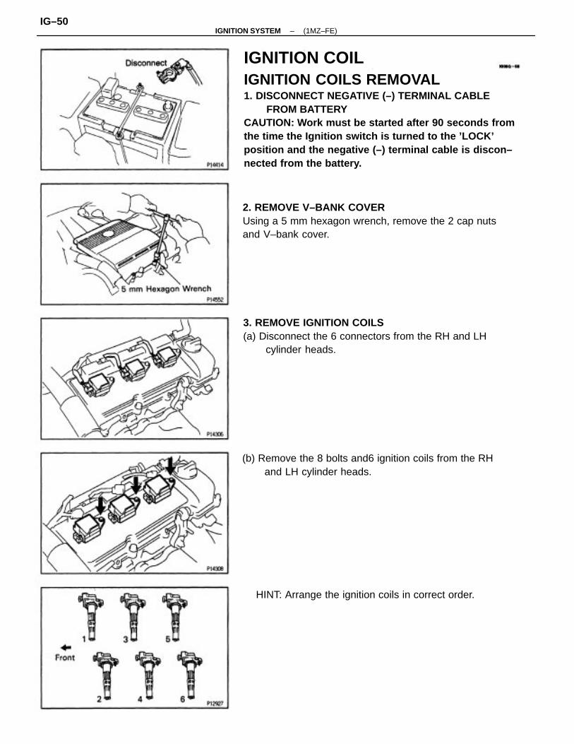
IGNITION COILIGNITION COILS REMOVAL1. DISCONNECT NEGATIVE (–) TERMINAL CABLE
FROM BATTERYCAUTION: Work must be started after 90 seconds fromthe time the Ignition switch is turned to the ’LOCK’position and the negative (–) terminal cable is discon–nected from the battery.
3. REMOVE IGNITION COILS(a) Disconnect the 6 connectors from the RH and LH
cylinder heads.
2. REMOVE V–BANK COVERUsing a 5 mm hexagon wrench, remove the 2 cap nutsand V–bank cover.
(b) Remove the 8 bolts and6 ignition coils from the RHand LH cylinder heads.
HINT: Arrange the ignition coils in correct order.
–IGNITION SYSTEM (1MZ–FE)IG–50

2. INSTALL V–BANK COVERUsing a 5 mm hexagon wrench, install the V–bankcover with the 2 cap nuts.HINT: For fixing the V–bank cover, push on the coveruntil sense of “click” is felt.
1. INSTALL IGNITION COILS(a) Install the6 ignition coils to the RH and LH cylinder
heads with the ^ bolts.Torque: 8 N–m (80 kgf–cm. 89 in.Ibf)
3. CONNECT NEGATIVE (–) TERMINAL CABLETO BATTERY
(b) Connect the 6 ignition coil connectors.
IGNITION COIL INSTALLATION
–IGNITION SYSTEM (1MZ–FE)IG–51

CAMSHAFT POSITION SENSORCAMSHAFT POSITION SENSOR REMOVAL1. DISCONNECT NEGATIVE (–) TERMINAL CABLE
FROM BATTERYCAUTION: Work must be started after 90 seconds fromthe time the ignition switch is turned to the “LOCK”position and the negative (–) terminal cable is discon–nected from the battery.
CAMSHAFT POSITION SENSORINSTALLATION1. INSTALL CRANKSHAFT POSITION SENSOR
Torque: 8 N–m (80 kgf–cm, 69 in.ibf)
2. CONNECT NEGATIVE (–) TERMINAL CABLETO BATTERY
2. REMOVE CAMSHAFT POSITION SENSOR(a) Disconnect the camshaft position sensor connector.(b) Remove the 2 bolts and camshaft position sensor.
–IGNITION SYSTEM (1MZ–FE)IG–52
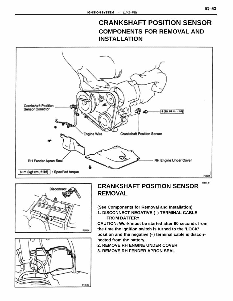
CRANKSHAFT POSITION SENSORREMOVAL
(See Components for Removal and Installation)1. DISCONNECT NEGATIVE (–) TERMINAL CABLE
FROM BATTERYCAUTION: Work must be started after 90 seconds fromthe time the Ignition switch is turned to the ’LOCK’position and the negative (–) terminal cable is discon–nected from the battery.2. REMOVE RH ENGINE UNDER COVER3. REMOVE RH FENDER APRON SEAL
CRANKSHAFT POSITION SENSORCOMPONENTS FOR REMOVAL ANDINSTALLATION
–IGNITION SYSTEM (1MZ–FE)IG–53

INSPECT CRANKSHAFT POSITION SENSORRESISTANCEUsing an ohmmeter, measure the resistance betweenterminals.Resistance (Cold): 1,630–2,740 0Resistance (Hot): 2,060–3,225 0If the resistance is not as specified, replace the crankshaft position sensor.
CRANKSHAFT POSITION SENSORINSPECTION
NOTICE: ’Cold’ and ’Hot’ in the following sentences ex–press the temperature of the sensors themselves. ’Cold’is from–10 �C (14�F) to 50�C (122�F) and ’Hot’ is from50�C (122�F) to 100�C (212�F).
5. REMOVE CRANKSHAFT POSITION SENSOR(a) Remove the bolt and disconnect the crankshaft posi–
tion sensor.(b) Disconnect the crankshaft position sensor conecter.
4. DISCONNECT ENGINE WIRERemove the 3 nuts and disconnect the engine wire.
–IGNITION SYSTEM (1MZ–FE)IG–54
CRANKSHAFT POSITION SENSORINSTALLATION
(See Components for Removal and Installation)1. INSTALL CRANKSHAFT POSITION SENSOR Torque: 8 N–m (80 kgf–cm, 69 in.lbf)2. CONNECT ENGINE WIRE3. INSTALL RH FENDER APRON SEAL4. INSTALL RH ENGINE UNDER COVER6. CONNECT NEGATIVE (–) TERMINAL CABLETO BATTERY
–IGNITION SYSTEM (1MZ–FE)IG–55
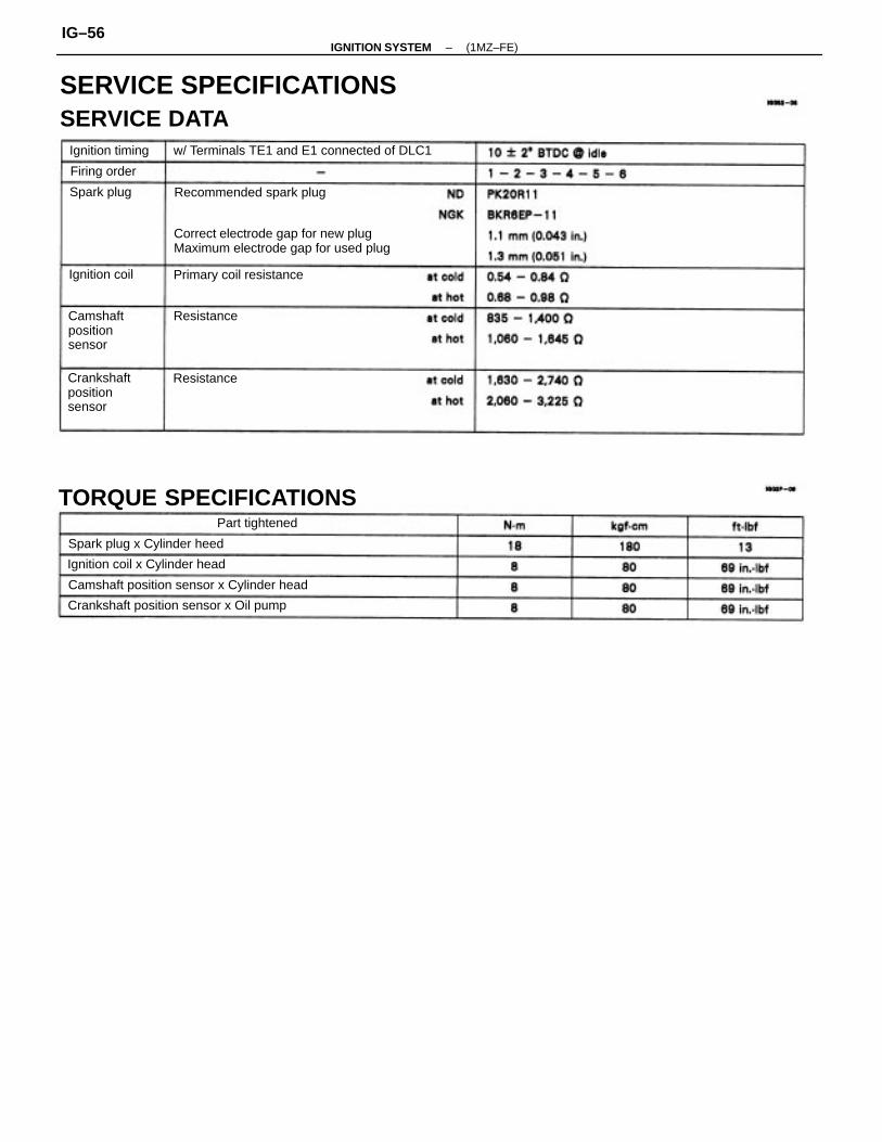
SERVICE SPECIFICATIONSSERVICE DATA
Correct electrode gap for new plugMaximum electrode gap for used plug
TORQUE SPECIFICATIONS
w/ Terminals TE1 and E1 connected of DLC1
Camshaft position sensor x Cylinder head
Crankshaft position sensor x Oil pump
Crankshaftpositionsensor
Ignition coil x Cylinder head
Camshaftpositionsensor
Spark plug x Cylinder heed
Recommended spark plug
Primary coil resistance
Ignition timing
Part tightened
Ignition coil
Firing order
Spark plug
Resistance
Resistance
–IGNITION SYSTEM (1MZ–FE)IG–56
Related Documents


