Welcome message from author
This document is posted to help you gain knowledge. Please leave a comment to let me know what you think about it! Share it to your friends and learn new things together.
Transcript
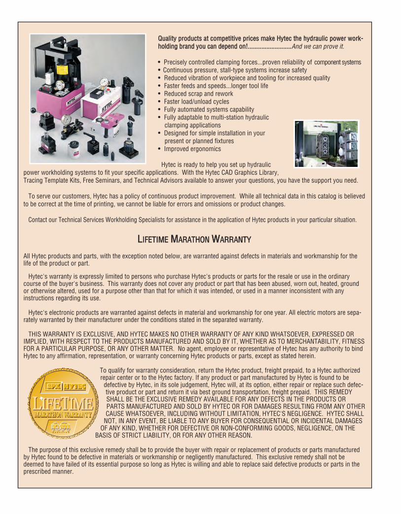
QQuuaalliittyy pprroodduuccttss aatt ccoommppeettiittiivvee pprriicceess mmaakkee HHyytteecc tthhee hhyyddrraauulliicc ppoowweerr wwoorrkk--hhoollddiinngg bbrraanndd yyoouu ccaann ddeeppeenndd oonn!!....................................................And we can prove it.
•• Precisely controlled clamping forces...proven reliability of component systems•• Continuous pressure, stall-type systems increase safety•• Reduced vibration of workpiece and tooling for increased quality•• Faster feeds and speeds...longer tool life•• Reduced scrap and rework•• Faster load/unload cycles•• Fully automated systems capability•• Fully adaptable to multi-station hydraulic
clamping applications•• Designed for simple installation in your
present or planned fixtures•• Improved ergonomics
Hytec is ready to help you set up hydraulicpower workholding systems to fit your specific applications. With the Hytec CAD Graphics Library,Tracing Template Kits, Free Seminars, and Technical Advisors available to answer your questions, you have the support you need.
To serve our customers, Hytec has a policy of continuous product improvement. While all technical data in this catalog is believedto be correct at the time of printing, we cannot be liable for errors and omissions or product changes.
Contact our Technical Services Workholding Specialists for assistance in the application of Hytec products in your particular situation.
LLIIFFEETTIIMMEE MMAARRAATTHHOONN WWAARRRRAANNTTYY
All Hytec products and parts, with the exception noted below, are warranted against defects in materials and workmanship for thelife of the product or part.
Hytec's warranty is expressly limited to persons who purchase Hytec's products or parts for the resale or use in the ordinarycourse of the buyer's business. This warranty does not cover any product or part that has been abused, worn out, heated, groundor otherwise altered, used for a purpose other than that for which it was intended, or used in a manner inconsistent with anyinstructions regarding its use.
Hytec's electronic products are warranted against defects in material and workmanship for one year. All electric motors are sepa-rately warranted by their manufacturer under the conditions stated in the separated warranty.
THIS WARRANTY IS EXCLUSIVE, AND HYTEC MAKES NO OTHER WARRANTY OF ANY KIND WHATSOEVER, EXPRESSED ORIMPLIED, WITH RESPECT TO THE PRODUCTS MANUFACTURED AND SOLD BY IT, WHETHER AS TO MERCHANTABILITY, FITNESSFOR A PARTICULAR PURPOSE, OR ANY OTHER MATTER. No agent, employee or representative of Hytec has any authority to bindHytec to any affirmation, representation, or warranty concerning Hytec products or parts, except as stated herein.
To qualify for warranty consideration, return the Hytec product, freight prepaid, to a Hytec authorizedrepair center or to the Hytec factory. If any product or part manufactured by Hytec is found to be
defective by Hytec, in its sole judgement, Hytec will, at its option, either repair or replace such defec-tive product or part and return it via best ground transportation, freight prepaid. THIS REMEDYSHALL BE THE EXCLUSIVE REMEDY AVAILABLE FOR ANY DEFECTS IN THE PRODUCTS ORPARTS MANUFACTURED AND SOLD BY HYTEC OR FOR DAMAGES RESULTING FROM ANY OTHERCAUSE WHATSOEVER, INCLUDING WITHOUT LIMITATION, HYTEC'S NEGLIGENCE. HYTEC SHALL
NOT, IN ANY EVENT, BE LIABLE TO ANY BUYER FOR CONSEQUENTIAL OR INCIDENTAL DAMAGESOF ANY KIND, WHETHER FOR DEFECTIVE OR NON-CONFORMING GOODS, NEGLIGENCE, ON THE
BASIS OF STRICT LIABILITY, OR FOR ANY OTHER REASON.
The purpose of this exclusive remedy shall be to provide the buyer with repair or replacement of products or parts manufacturedby Hytec found to be defective in materials or workmanship or negligently manufactured. This exclusive remedy shall not bedeemed to have failed of its essential purpose so long as Hytec is willing and able to replace said defective products or parts in theprescribed manner.
1
Table of Contents
AAllpphhaabbeettiiccaall IInnddeexx 22
NNuummeerriiccaall IInnddeexx 33--44
PPoowweerr WWoorrkkhhoollddiinngg SSyysstteemmss 55--77
DDeessiiggnn IInnffoorrmmaattiioonn 88--1133
CCoonnvveerrssiioonn FFoorrmmuullaass 1144
WWoorrkkhhoollddiinngg DDeevviicceess 1155
Cylinders ............................................................ 16-33Clamps ............................................................... 30-66Work Supports ................................................... 67-78
PPoowweerr SSoouurrcceess 7799
Power Source Information .................................. 80Electric/Hydraulic ................................................ 81-84Hydraulic Intensifier ............................................ 85Air/Hydraulic ....................................................... 86-90Pallet Coupling Pump.......................................... 91
CCoonnttrrooll VVaallvveess 9922
Control Valve Information.................................... 93Directional ...........................................................94-101Pressure.............................................................102-103Flow...................................................................104-106
PPaalllleettiizzeedd SSyysstteemmss ............................................................................................................................ 110077Palletizing Information.......................................... 108Single-Acting Manual Pallet Coupler System......109-116Accumulators ....................................................... 117Double-Acting Manual Pallet Coupler System ...... 118Remote Mounted Control Valve............................ 119
AAcccceessssoorriieess 112200
Fittings ...............................................................121-126Hydraulic Fluid, Hoses and Tubing ...................... 127Couplers .............................................................. 128Manifolds............................................................. 129High Pressure In-line Filters ................................ 130Pressure Gauges.................................................. 131Rotating Unions................................................... 132Pressure Switch................................................... 133Remote Controls.................................................. 134Fluid Level/Temperature Gauge and Reservoirs... 135Pressure Monitoring System............................... 136
SSaaffeettyy IInnffoorrmmaattiioonn 113377
2
AAAccumulators....................................................................................................117
BBBases, Work Support.....................................................................................67-72Brackets, Flange Mounting..................................................................................60 Brackets, Foot Mounting ...............................................................................19, 21Bushing, Connector ..........................................................................................122
CCCams, Swing/Pull Clamp.....................................................................................57Caps, Feeder ...........................................................................................19, 21, 73Charging Tool, Accumulator .............................................................................124Clamp Arms, Swing/Pull .....................................................................................58Clamp, Die ..........................................................................................................66Clamp, Edge........................................................................................................65Clamp, Swing/Pull .........................................................................................35-57Clamp, Swing......................................................................................................61Clamp, Tapered Screw Expanded........................................................................30Clamps, Retract ..................................................................................................63Clamps, Uniforce ................................................................................................26Couplers ...........................................................................................................128Cylinders, Block Style .........................................................................................22Cylinders, Cartridge Pull ...............................................................................24, 28Cylinders, Center Hole ........................................................................................20Cylinders, Low Profile .........................................................................................21Cylinders, Threaded Body ...................................................................................17Cylinders, Threaded Body, Side Port...................................................................18
FFFilters, High Pressure In-Line ...........................................................................130Fitting, Adapter .................................................................................................122Fitting, Connector .....................................................................................122, 123Fitting, Reducer.................................................................................................122Fittings, 45 Degree Male Elbow.........................................................................121Fittings, 90 Degree Male Elbow.................................................................121, 123Fittings, 90 Degree Swivel Adapter ...................................................................123Fittings, Cross...................................................................................................121Fittings, Male Adapter .......................................................................................123Fittings, Male Branch Tee ..........................................................................121-123Fittings, Male Connector ...........................................................................122, 123Fittings, Male Run Tee ......................................................................................121Fittings, Male Union ..........................................................................................121Fittings, Plug.....................................................................................................122Fittings, Swivel Adapter ............................................................................122, 123Fittings, Tube Sleeve .........................................................................................122Fittings, Union Tee ............................................................................................121Fluid, “Environmentally Friendly” Hydraulic ......................................................127Fluid, Fire Resistant Hydraulic...........................................................................127
GGGauge, Fluid Level/Temperature........................................................................135Gauges, Hydraulic Pressure..............................................................................131
HHHoses, Hydraulic...............................................................................................127
IIInserts, Threaded, Crowned................................................................................23Inserts, Threaded, Pointed ..................................................................................23Inserts, Threaded, Toggle Pad ............................................................................23Intensifiers, Hydraulic .........................................................................................85
Alphabetical Index
KKKits, Metal Reservoir Conversion ......................................................................135
MMManifold, 7 Port ................................................................................................129Manifold, Assembly ..........................................................................................129
NNNuts, Jam .....................................................................................................19, 60
OOOil, Hydraulic ....................................................................................................127
PPPallet Disconnect Handle ..................................................................................112Pumps, Air/Hydraulic.....................................................................................87-90Pumps, Electric/Hydraulic .............................................................................81-84Pumps, Manual Pallet Coupling.................................................................113-116
RRRemote Control.................................................................................................134Restrictor Valve, Accumulator ..........................................................................117Rotating Unions ................................................................................................132
SSSwitch, Pressure...............................................................................................133Switch, Remote Hand .......................................................................................134
TTTubing, Steel.....................................................................................................127
VVValve, Check ...............................................................................................96, 122Valve, Manual Pallet..................................................................................110, 111Valve, Metering .................................................................................................123Valve, Pressure Reducing .................................................................................103Valve, Pressure Reducing Manifold Mounted ...................................................103Valve, Pressure Sequence.................................................................................102Valve, Pressure Sequence Manifold Mounted ...................................................102Valve, Pump Mounted.........................................................................................99Valve, Remote Manifold Mounted .............................................................100, 101Valves, Needle...................................................................................................105Valves, Pilot Operated Check ............................................................................104Valves, Remote Mounted ......................................................94, 95, 100, 101, 119Valves, Manifold Mounted Control ......................................................................97Valves, Control Accessories................................................................................98Valves, High Pressure Ball ................................................................................106
WWWork Supports, Air Advance...................................................................72, 77, 78Work Supports, Air Advance Manifold Mounted ...........................................72, 77Work Supports, Fluid Advance......................................................................68, 69Work Supports, Fluid Advance Manifold Mounted ........................................68, 69Work Supports, Internally Vented .................................................................72, 73Work Supports, Spring Advance.................................................70, 71, 74, 75, 76 Work Supports, Spring Advance Manifold Mounted ...................70, 71, 74, 75, 76
PPAAGGEEDDEESSCCRRIIPPTTIIOONN NNOO..
PPAAGGEEDDEESSCCRRIIPPTTIIOONN NNOO..
3
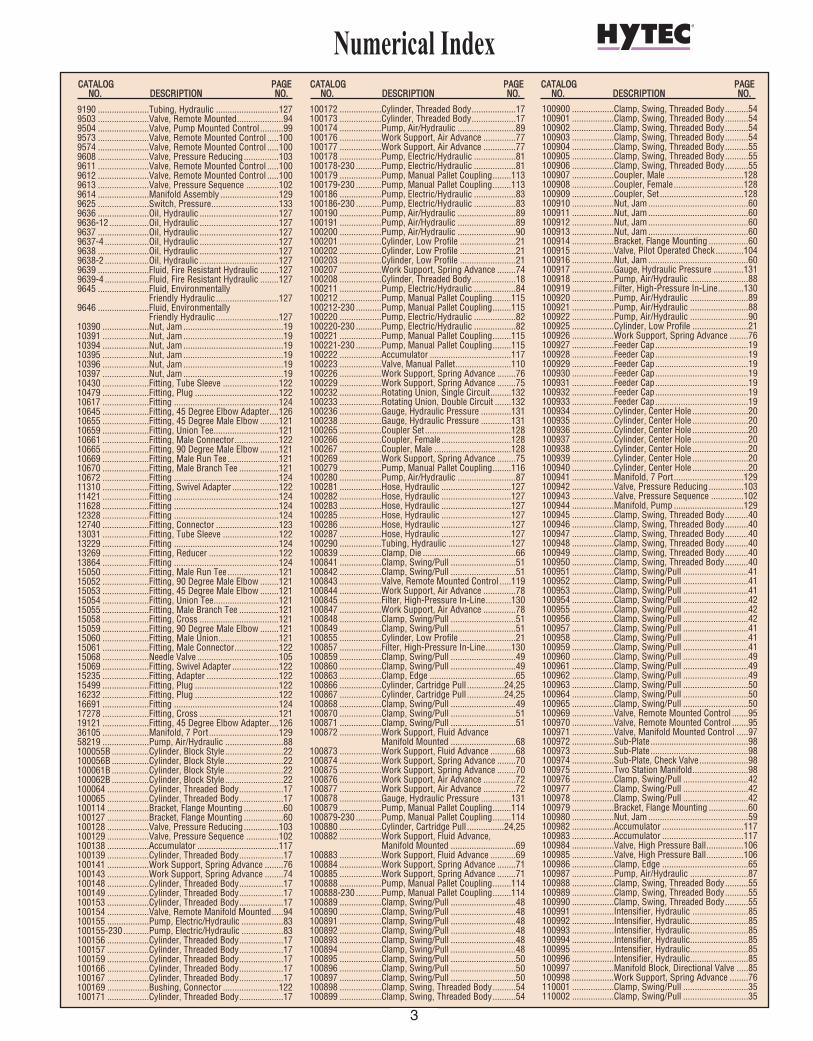
Numerical Index
9190 ......................Tubing, Hydraulic ...........................1279503 ......................Valve, Remote Mounted....................949504 ......................Valve, Pump Mounted Control ..........999573 ......................Valve, Remote Mounted Control .....1009574 ......................Valve, Remote Mounted Control .....1009608 ......................Valve, Pressure Reducing...............1039611 ......................Valve, Remote Mounted Control .....1009612 ......................Valve, Remote Mounted Control .....1009613 ......................Valve, Pressure Sequence ..............1029614 ......................Manifold Assembly .........................1299625 ......................Switch, Pressure.............................1339636 ......................Oil, Hydraulic ..................................1279636-12 .................Oil, Hydraulic ..................................1279637 ......................Oil, Hydraulic ..................................1279637-4 ...................Oil, Hydraulic ..................................1279638 ......................Oil, Hydraulic ..................................1279638-2 ...................Oil, Hydraulic ..................................1279639 ......................Fluid, Fire Resistant Hydraulic ........1279639-4 ...................Fluid, Fire Resistant Hydraulic ........1279645 ......................Fluid, Environmentally
Friendly Hydraulic ...........................1279646 ......................Fluid, Environmentally
Friendly Hydraulic ...........................12710390 ....................Nut, Jam...........................................1910391 ....................Nut, Jam...........................................1910394 ....................Nut, Jam...........................................1910395 ....................Nut, Jam...........................................1910396 ....................Nut, Jam...........................................1910397 ....................Nut, Jam...........................................1910430 ....................Fitting, Tube Sleeve ........................12210479 ....................Fitting, Plug ....................................12210617 ....................Fitting .............................................12410645 ....................Fitting, 45 Degree Elbow Adapter....12610655 ....................Fitting, 45 Degree Male Elbow ........12110659 ....................Fitting, Union Tee............................12110661 ....................Fitting, Male Connector...................12210665 ....................Fitting, 90 Degree Male Elbow ........12110669 ....................Fitting, Male Run Tee......................12110670 ....................Fitting, Male Branch Tee .................12110672 ....................Fitting .............................................12411310 ....................Fitting, Swivel Adapter ....................12211421 ....................Fitting .............................................12411628 ....................Fitting .............................................12412328 ....................Fitting .............................................12412740 ....................Fitting, Connector ...........................12313031 ....................Fitting, Tube Sleeve ........................12213229 ....................Fitting .............................................12413269 ....................Fitting, Reducer ..............................12213864 ....................Fitting .............................................12415050 ....................Fitting, Male Run Tee......................12115052 ....................Fitting, 90 Degree Male Elbow ........12115053 ....................Fitting, 45 Degree Male Elbow ........12115054 ....................Fitting, Union Tee............................12115055 ....................Fitting, Male Branch Tee .................12115058 ....................Fitting, Cross ..................................12115059 ....................Fitting, 90 Degree Male Elbow ........12115060 ....................Fitting, Male Union..........................12115061 ....................Fitting, Male Connector...................12215068 ....................Needle Valve ...................................10515069 ....................Fitting, Swivel Adapter ....................12215235 ....................Fitting, Adapter ...............................12215499 ....................Fitting, Plug ....................................12216232 ....................Fitting, Plug ....................................12216691 ....................Fitting .............................................12417278 ....................Fitting, Cross ..................................12119121 ....................Fitting, 45 Degree Elbow Adapter....12636105 ....................Manifold, 7 Port..............................12958219 ....................Pump, Air/Hydraulic .........................88100055B ................Cylinder, Block Style .........................22100056B ................Cylinder, Block Style .........................22100061B ................Cylinder, Block Style .........................22100062B ................Cylinder, Block Style .........................22100064 ..................Cylinder, Threaded Body...................17100065 ..................Cylinder, Threaded Body...................17100114 ..................Bracket, Flange Mounting .................60100127 ..................Bracket, Flange Mounting .................60100128 ..................Valve, Pressure Reducing...............103100129 ..................Valve, Pressure Sequence ..............102100138 ..................Accumulator ...................................117100139 ..................Cylinder, Threaded Body...................17100141 ..................Work Support, Spring Advance ........76100143 ..................Work Support, Spring Advance ........74100148 ..................Cylinder, Threaded Body...................17100149 ..................Cylinder, Threaded Body...................17100153 ..................Cylinder, Threaded Body...................17100154 ..................Valve, Remote Manifold Mounted.....94100155 ..................Pump, Electric/Hydraulic ..................83100155-230 ...........Pump, Electric/Hydraulic ..................83100156 ..................Cylinder, Threaded Body...................17100157 ..................Cylinder, Threaded Body...................17100159 ..................Cylinder, Threaded Body...................17100166 ..................Cylinder, Threaded Body...................17100167 ..................Cylinder, Threaded Body...................17100169 ..................Bushing, Connector ........................122100171 ..................Cylinder, Threaded Body...................17
100172 ..................Cylinder, Threaded Body...................17100173 ..................Cylinder, Threaded Body...................17100174 ..................Pump, Air/Hydraulic .........................89100176 ..................Work Support, Air Advance ..............77100177 ..................Work Support, Air Advance ..............77100178 ..................Pump, Electric/Hydraulic ..................81100178-230 ...........Pump, Electric/Hydraulic ..................81100179 ..................Pump, Manual Pallet Coupling........113100179-230 ...........Pump, Manual Pallet Coupling........113100186 ..................Pump, Electric/Hydraulic ..................83100186-230 ...........Pump, Electric/Hydraulic ..................83100190 ..................Pump, Air/Hydraulic .........................89100191 ..................Pump, Air/Hydraulic .........................89100200 ..................Pump, Air/Hydraulic .........................90100201 ..................Cylinder, Low Profile ........................21100202 ..................Cylinder, Low Profile ........................21100203 ..................Cylinder, Low Profile ........................21100207 ..................Work Support, Spring Advance ........74100208 ..................Cylinder, Threaded Body...................18100211 ..................Pump, Electric/Hydraulic ..................84100212 ..................Pump, Manual Pallet Coupling........115100212-230 ...........Pump, Manual Pallet Coupling........115100220 ..................Pump, Electric/Hydraulic ..................82100220-230 ...........Pump, Electric/Hydraulic ..................82100221 ..................Pump, Manual Pallet Coupling........115100221-230 ...........Pump, Manual Pallet Coupling........115100222 ..................Accumulator ...................................117100223 ..................Valve, Manual Pallet........................110100226 ..................Work Support, Spring Advance ........76100229 ..................Work Support, Spring Advance ........75100232 ..................Rotating Union, Single Circuit.........132100233 ..................Rotating Union, Double Circuit .......132100236 ..................Gauge, Hydraulic Pressure .............131100238 ..................Gauge, Hydraulic Pressure .............131100265 ..................Coupler Set .....................................128100266 ..................Coupler, Female ..............................128100267 ..................Coupler, Male .................................128100269 ..................Work Support, Spring Advance ........75100279 ..................Pump, Manual Pallet Coupling........116100280 ..................Pump, Air/Hydraulic .........................87100281 ..................Hose, Hydraulic ..............................127100282 ..................Hose, Hydraulic ..............................127100283 ..................Hose, Hydraulic ..............................127100285 ..................Hose, Hydraulic ..............................127100286 ..................Hose, Hydraulic ..............................127100287 ..................Hose, Hydraulic ..............................127100290 ..................Tubing, Hydraulic ...........................127100839 ..................Clamp, Die ........................................66100841 ..................Clamp, Swing/Pull ............................51100842 ..................Clamp, Swing/Pull ............................51100843 ..................Valve, Remote Mounted Control .....119100844 ..................Work Support, Air Advance ..............78100845 ..................Filter, High-Pressure In-Line...........130100847 ..................Work Support, Air Advance ..............78100848 ..................Clamp, Swing/Pull ............................51100849 ..................Clamp, Swing/Pull ............................51100855 ..................Cylinder, Low Profile ........................21100857 ..................Filter, High-Pressure In-Line...........130100859 ..................Clamp, Swing/Pull ............................49100860 ..................Clamp, Swing/Pull ............................49100863 ..................Clamp, Edge .....................................65100866 ..................Cylinder, Cartridge Pull ................24,25100867 ..................Cylinder, Cartridge Pull ................24,25100868 ..................Clamp, Swing/Pull ............................49100870 ..................Clamp, Swing/Pull ............................51100871 ..................Clamp, Swing/Pull ............................51100872 ..................Work Support, Fluid Advance
Manifold Mounted ............................68100873 ..................Work Support, Fluid Advance ...........68100874 ..................Work Support, Spring Advance ........70100875 ..................Work Support, Spring Advance ........70100876 ..................Work Support, Air Advance ..............72100877 ..................Work Support, Air Advance ..............72100878 ..................Gauge, Hydraulic Pressure .............131100879 ..................Pump, Manual Pallet Coupling........114100879-230 ...........Pump, Manual Pallet Coupling........114100880 ..................Cylinder, Cartridge Pull ................24,25100882 ..................Work Support, Fluid Advance,
Manifold Mounted ............................69100883 ..................Work Support, Fluid Advance ...........69100884 ..................Work Support, Spring Advance ........71100885 ..................Work Support, Spring Advance ........71100888 ..................Pump, Manual Pallet Coupling........114100888-230 ...........Pump, Manual Pallet Coupling........114100889 ..................Clamp, Swing/Pull ............................48100890 ..................Clamp, Swing/Pull ............................48100891 ..................Clamp, Swing/Pull ............................48100892 ..................Clamp, Swing/Pull ............................48100893 ..................Clamp, Swing/Pull ............................48100894 ..................Clamp, Swing/Pull ............................48100895 ..................Clamp, Swing/Pull ............................50100896 ..................Clamp, Swing/Pull ............................50100897 ..................Clamp, Swing/Pull ............................50100898 ..................Clamp, Swing, Threaded Body..........54100899 ..................Clamp, Swing, Threaded Body..........54
100900 ..................Clamp, Swing, Threaded Body..........54100901 ..................Clamp, Swing, Threaded Body..........54100902 ..................Clamp, Swing, Threaded Body..........54100903 ..................Clamp, Swing, Threaded Body..........54100904 ..................Clamp, Swing, Threaded Body..........55100905 ..................Clamp, Swing, Threaded Body..........55100906 ..................Clamp, Swing, Threaded Body..........55100907 ..................Coupler, Male .................................128100908 ..................Coupler, Female ..............................128100909 ..................Coupler, Set ....................................128100910 ..................Nut, Jam...........................................60100911 ..................Nut, Jam...........................................60100912 ..................Nut, Jam...........................................60100913 ..................Nut, Jam...........................................60100914 ..................Bracket, Flange Mounting .................60100915 ..................Valve, Pilot Operated Check............104100916 ..................Nut, Jam...........................................60100917 ..................Gauge, Hydraulic Pressure .............131100918 ..................Pump, Air/Hydraulic .........................88100919 ..................Filter, High-Pressure In-Line...........130100920 ..................Pump, Air/Hydraulic .........................89100921 ..................Pump, Air/Hydraulic .........................88100922 ..................Pump, Air/Hydraulic .........................90100925 ..................Cylinder, Low Profile ........................21100926 ..................Work Support, Spring Advance ........76100927 ..................Feeder Cap........................................19100928 ..................Feeder Cap........................................19100929 ..................Feeder Cap........................................19100930 ..................Feeder Cap........................................19100931 ..................Feeder Cap........................................19100932 ..................Feeder Cap........................................19100933 ..................Feeder Cap........................................19100934 ..................Cylinder, Center Hole ........................20100935 ..................Cylinder, Center Hole ........................20100936 ..................Cylinder, Center Hole ........................20100937 ..................Cylinder, Center Hole ........................20100938 ..................Cylinder, Center Hole ........................20100939 ..................Cylinder, Center Hole ........................20100940 ..................Cylinder, Center Hole ........................20100941 ..................Manifold, 7 Port..............................129100942 ..................Valve, Pressure Reducing...............103100943 ..................Valve, Pressure Sequence ..............102100944 ..................Manifold, Pump ..............................129100945 ..................Clamp, Swing, Threaded Body..........40100946 ..................Clamp, Swing, Threaded Body..........40100947 ..................Clamp, Swing, Threaded Body..........40100948 ..................Clamp, Swing, Threaded Body..........40100949 ..................Clamp, Swing, Threaded Body..........40100950 ..................Clamp, Swing, Threaded Body..........40100951 ..................Clamp, Swing/Pull ............................41100952 ..................Clamp, Swing/Pull ............................41100953 ..................Clamp, Swing/Pull ............................41100954 ..................Clamp, Swing/Pull ............................42100955 ..................Clamp, Swing/Pull ............................42100956 ..................Clamp, Swing/Pull ............................42100957 ..................Clamp, Swing/Pull ............................41100958 ..................Clamp, Swing/Pull ............................41100959 ..................Clamp, Swing/Pull ............................41100960 ..................Clamp, Swing/Pull ............................49100961 ..................Clamp, Swing/Pull ............................49100962 ..................Clamp, Swing/Pull ............................49100963 ..................Clamp, Swing/Pull ............................50100964 ..................Clamp, Swing/Pull ............................50100965 ..................Clamp, Swing/Pull ............................50100969 ..................Valve, Remote Mounted Control .......95100970 ..................Valve, Remote Mounted Control .......95100971 ..................Valve, Manifold Mounted Control .....97100972 ..................Sub-Plate ..........................................98100973 ..................Sub-Plate ..........................................98100974 ..................Sub-Plate, Check Valve.....................98100975 ..................Two Station Manifold........................98100976 ..................Clamp, Swing/Pull ............................42100977 ..................Clamp, Swing/Pull ............................42100978 ..................Clamp, Swing/Pull ............................42100979 ..................Bracket, Flange Mounting .................60100980 ..................Nut, Jam...........................................59100982 ..................Accumulator ...................................117100983 ..................Accumulator ...................................117100984 ..................Valve, High Pressure Ball................106100985 ..................Valve, High Pressure Ball................106100986 ..................Clamp, Edge .....................................65100987 ..................Pump, Air/Hydraulic .........................87100988 ..................Clamp, Swing, Threaded Body..........55100989 ..................Clamp, Swing, Threaded Body..........55100990 ..................Clamp, Swing, Threaded Body..........55100991 ..................Intensifier, Hydraulic ........................85100992 ..................Intensifier, Hydraulic.........................85100993 ..................Intensifier, Hydraulic.........................85100994 ..................Intensifier, Hydraulic.........................85100995 ..................Intensifier, Hydraulic.........................85100996 ..................Intensifier, Hydraulic.........................85100997 ..................Manifold Block, Directional Valve .....85100998 ..................Work Support, Spring Advance ........76110001 ..................Clamp, Swing/Pull ............................35110002 ..................Clamp, Swing/Pull ............................35
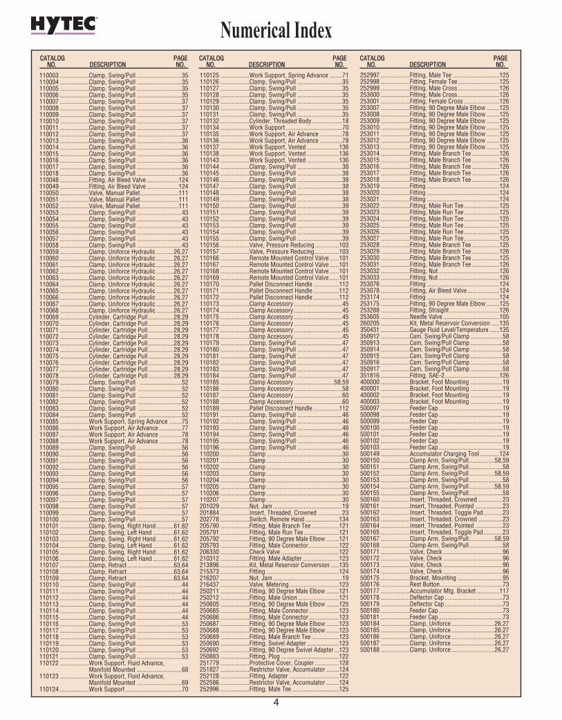
CCAATTAALLOOGG PPAAGGEENNOO.. DDEESSCCRRIIPPTTIIOONN NNOO..
CCAATTAALLOOGG PPAAGGEENNOO.. DDEESSCCRRIIPPTTIIOONN NNOO..
CCAATTAALLOOGG PPAAGGEENNOO.. DDEESSCCRRIIPPTTIIOONN NNOO..
4
Numerical Index
110003 ..................Clamp, Swing/Pull ............................35110004 ..................Clamp, Swing/Pull ............................35110005 ..................Clamp, Swing/Pull ............................35110006 ..................Clamp, Swing/Pull ............................35110007 ..................Clamp, Swing/Pull ............................37110008 ..................Clamp, Swing/Pull ............................37110009 ..................Clamp, Swing/Pull ............................37110010 ..................Clamp, Swing/Pull ............................37110011 ..................Clamp, Swing/Pull ............................37110012 ..................Clamp, Swing/Pull ............................37110013 ..................Clamp, Swing/Pull ............................36110014 ..................Clamp, Swing/Pull ............................36110015 ..................Clamp, Swing/Pull ............................36110016 ..................Clamp, Swing/Pull ............................36110017 ..................Clamp, Swing/Pull ............................36110018 ..................Clamp, Swing/Pull ............................36110048 ..................Fitting, Air Bleed Valve....................124110049 ..................Fitting, Air Bleed Valve....................124110050 ..................Valve, Manual Pallet........................111110051 ..................Valve, Manual Pallet........................111110052 ..................Valve, Manual Pallet........................111110053 ..................Clamp, Swing/Pull ............................43110054 ..................Clamp, Swing/Pull ............................43110055 ..................Clamp, Swing/Pull ............................43110056 ..................Clamp, Swing/Pull ............................43110057 ..................Clamp, Swing/Pull ............................43110058 ..................Clamp, Swing/Pull ............................43110059 ..................Clamp, Uniforce Hydraulic ...........26,27110060 ..................Clamp, Uniforce Hydraulic ...........26,27110061 ..................Clamp, Uniforce Hydraulic ...........26,27110062 ..................Clamp, Uniforce Hydraulic ...........26,27110063 ..................Clamp, Uniforce Hydraulic ...........26,27110064 ..................Clamp, Uniforce Hydraulic ...........26,27110065 ..................Clamp, Uniforce Hydraulic ...........26,27110066 ..................Clamp, Uniforce Hydraulic ...........26,27110067 ..................Clamp, Uniforce Hydraulic ...........26,27110068 ..................Clamp, Uniforce Hydraulic ...........26,27110069 ..................Cylinder, Cartridge Pull ................28,29110070 ..................Cylinder, Cartridge Pull ................28,29110071 ..................Cylinder, Cartridge Pull ................28,29110072 ..................Cylinder, Cartridge Pull ................28,29110073 ..................Cylinder, Cartridge Pull ................28,29110074 ..................Cylinder, Cartridge Pull ................28,29110075 ..................Cylinder, Cartridge Pull ................28,29110076 ..................Cylinder, Cartridge Pull ................28,29110077 ..................Cylinder, Cartridge Pull ................28,29110078 ..................Cylinder, Cartridge Pull ................28,29110079 ..................Clamp, Swing/Pull ..........................52110080 ..................Clamp, Swing/Pull ...........................52110081 ..................Clamp, Swing/Pull ...........................52110082 ..................Clamp, Swing/Pull ...........................52110083 ..................Clamp, Swing/Pull ...........................52110084 ..................Clamp, Swing/Pull ...........................52110085 ..................Work Support, Spring Advance ........75110086 ..................Work Support, Air Advance ..............77110087 ..................Work Support, Air Advance ..............78110088 ..................Work Support, Air Advance ..............78110089 ..................Clamp, Swing/Pull ............................56110090 ..................Clamp, Swing/Pull ............................56110091 ..................Clamp, Swing/Pull ............................56110092 ..................Clamp, Swing/Pull ............................56110093 ..................Clamp, Swing/Pull ............................56110094 ..................Clamp, Swing/Pull ............................56110095 ..................Clamp, Swing/Pull ............................57110096 ..................Clamp, Swing/Pull ............................57110097 ..................Clamp, Swing/Pull ............................57110098 ..................Clamp, Swing/Pull ............................57110099 ..................Clamp, Swing/Pull ............................57110100 ..................Clamp, Swing/Pull ............................57110101 ..................Clamp, Swing, Right Hand...........61,62110102 ..................Clamp, Swing, Left Hand .............61,62110103 ..................Clamp, Swing, Right Hand...........61,62110104 ..................Clamp, Swing, Left Hand .............61,62110105 ..................Clamp, Swing, Right Hand...........61,62110106 ..................Clamp, Swing, Left Hand .............61,62110107 ..................Clamp, Retract .............................63,64110108 ..................Clamp, Retract .............................63,64110109 ..................Clamp, Retract .............................63,64110110 ..................Clamp, Swing/Pull ............................44110111 ..................Clamp, Swing/Pull ............................44110112 ..................Clamp, Swing/Pull ............................44110113 ..................Clamp, Swing/Pull ............................44110114 ..................Clamp, Swing/Pull ............................44110115 ..................Clamp, Swing/Pull ............................44110116 ..................Clamp, Swing/Pull ............................53110117 ..................Clamp, Swing/Pull ............................53110118 ..................Clamp, Swing/Pull ............................53110119 ..................Clamp, Swing/Pull ............................53110120 ..................Clamp, Swing/Pull ............................53110121 ..................Clamp, Swing/Pull ............................53110122 ..................Work Support, Fluid Advance,
Manifold Mounted ............................68110123 ..................Work Support, Fluid Advance,
Manifold Mounted ............................69110124 ..................Work Support ...................................70
110125 ..................Work Support, Spring Advance ........71110126 ..................Clamp, Swing/Pull ............................35110127 ..................Clamp, Swing/Pull ............................35110128 ..................Clamp, Swing/Pull ............................35110129 ..................Clamp, Swing/Pull ............................35110130 ..................Clamp, Swing/Pull ............................35110131 ..................Clamp, Swing/Pull ............................35110132 ..................Cylinder, Threaded Body...................18110134 ..................Work Support ...................................70110135 ..................Work Support, Air Advance ..............78110136 ..................Work Support, Air Advance ..............78110137 ..................Work Support, Vented ....................136110138 ..................Work Support, Vented ....................136110143 ..................Work Support, Vented ....................136110144 ..................Clamp, Swing/Pull ............................38110145 ..................Clamp, Swing/Pull ............................38110146 ..................Clamp, Swing/Pull ............................38110147 ..................Clamp, Swing/Pull ............................38110148 ..................Clamp, Swing/Pull ............................38110149 ..................Clamp, Swing/Pull ............................38110150 ..................Clamp, Swing/Pull ............................39110151 ..................Clamp, Swing/Pull ............................39110152 ..................Clamp, Swing/Pull ............................39110153 ..................Clamp, Swing/Pull ............................39110154 ..................Clamp, Swing/Pull ............................39110155 ..................Clamp, Swing/Pull ............................39110156 ..................Valve, Pressure Reducing...............103110157 ..................Valve, Pressure Reducing...............103110166 ..................Remote Mounted Control Valve ......101110167 ..................Remote Mounted Control Valve ......101110168 ..................Remote Mounted Control Valve ......101110169 ..................Remote Mounted Control Valve ......101110170 ..................Pallet Disconnect Handle ................112110171 ..................Pallet Disconnect Handle ................112110172 ..................Pallet Disconnect Handle ................112110173 ..................Clamp Accessory ..............................45110174 ..................Clamp Accessory ..............................45110175 ..................Clamp Accessory ..............................45110176 ..................Clamp Accessory ..............................45110177 ..................Clamp Accessory ..............................45110178 ..................Clamp Accessory ..............................45110179 ..................Clamp, Swing/Pull ............................47110180 ..................Clamp, Swing/Pull ............................47110181 ..................Clamp, Swing/Pull ............................47110182 ..................Clamp, Swing/Pull ............................47110183 ..................Clamp, Swing/Pull ............................47110184 ..................Clamp, Swing/Pull ............................47110185 ..................Clamp Accessory .........................58,59110186 ..................Clamp Accessory ..............................58110187 ..................Clamp Accessory ..............................60110188 ..................Clamp Accessory ..............................60110189 ..................Pallet Disconnect Handle ................112110191 ..................Clamp, Swing/Pull ............................46110192 ..................Clamp, Swing/Pull ............................46110193 ..................Clamp, Swing/Pull ............................46110194 ..................Clamp, Swing/Pull ............................46110195 ..................Clamp, Swing/Pull ............................46110196 ..................Clamp, Swing/Pull ............................46110200 ..................Clamp ...............................................30110201 ..................Clamp ...............................................30110202 ..................Clamp ...............................................30110203 ..................Clamp ...............................................30110204 ..................Clamp ...............................................30110205 ..................Clamp ...............................................30110206 ..................Clamp ...............................................30110207 ..................Clamp ...............................................30201029 ..................Nut, Jam...........................................19201884 ..................Insert, Threaded, Crowned ...............23202778 ..................Switch, Remote Hand .....................134205790 ..................Fitting, Male Branch Tee .................121205791 ..................Fitting, Male Run Tee......................121205792 ..................Fitting, 90 Degree Male Elbow ........121205793 ..................Fitting, Male Connector...................122206330 ..................Check Valve ....................................122210312 ..................Fitting, Male Adapter.......................123213896 ..................Kit, Metal Reservoir Conversion .....135215373 ..................Fitting .............................................124216207 ..................Nut, Jam...........................................19216437 ..................Valve, Metering...............................123250211 ..................Fitting, 90 Degree Male Elbow ........121250212 ..................Fitting, Male Union..........................121250605 ..................Fitting, 90 Degree Male Elbow ........125250685 ..................Fitting, Male Connector...................123250686 ..................Fitting, Male Connector...................123250687 ..................Fitting, 90 Degree Male Elbow ........123250688 ..................Fitting, 90 Degree Male Elbow ........123250689 ..................Fitting, Male Branch Tee .................123250690 ..................Fitting, Swivel Adapter ....................123250692 ..................Fitting, 90 Degree Swivel Adapter ...123250883 ..................Fitting, Plug ....................................122251779 ..................Protective Cover, Coupler ...............128251827 ..................Restrictor Valve, Accumulator ........124252128 ..................Fitting, Adapter ...............................122252586 ..................Restrictor Valve, Accumulator ........124252996 ..................Fitting, Male Tee .............................125
252997 ..................Fitting, Male Tee .............................125252998 ..................Fitting, Female Tee..........................125252999 ..................Fitting, Male Cross..........................126253000 ..................Fitting, Male Cross..........................126253001 ..................Fitting, Female Cross ......................126253007 ..................Fitting, 90 Degree Male Elbow ........125253008 ..................Fitting, 90 Degree Male Elbow ........125253009 ..................Fitting, 90 Degree Male Elbow ........125253010 ..................Fitting, 90 Degree Male Elbow ........125253011 ..................Fitting, 90 Degree Male Elbow ........125253012 ..................Fitting, 90 Degree Male Elbow ........125253013 ..................Fitting, 90 Degree Male Elbow ........125253014 ..................Fitting, Male Branch Tee .................126253015 ..................Fitting, Male Branch Tee .................126253016 ..................Fitting, Male Branch Tee .................126253017 ..................Fitting, Male Branch Tee .................126253018 ..................Fitting, Male Branch Tee .................126253019 ..................Fitting .............................................124253020 ..................Fitting .............................................124253021 ..................Fitting .............................................124253022 ..................Fitting, Male Run Tee......................125253023 ..................Fitting, Male Run Tee......................125253024 ..................Fitting, Male Run Tee......................125253025 ..................Fitting, Male Run Tee......................125253026 ..................Fitting, Male Run Tee......................125253027 ..................Fitting, Male Run Tee......................125253028 ..................Fitting, Male Branch Tee .................125253029 ..................Fitting, Male Branch Tee .................126253030 ..................Fitting, Male Branch Tee .................125253031 ..................Fitting, Male Branch Tee .................126253032 ..................Fitting, Nut ......................................126253033 ..................Fitting, Nut ......................................126253076 ..................Fitting .............................................124253078 ..................Fitting, Air Bleed Valve....................124253174 ..................Fitting .............................................124253175 ..................Fitting, 90 Degree Male Elbow ........125253288 ..................Fitting, Straight ...............................126253605 ..................Needle Valve ...................................105260205 ..................Kit, Metal Reservoir Conversion .....135350431 ..................Gauge Fluid Level/Temperature ......135350912 ..................Cam, Swing/Pull Clamp ....................58350913 ..................Cam, Swing/Pull Clamp ....................58350914 ..................Cam, Swing/Pull Clamp ....................58350915 ..................Cam, Swing/Pull Clamp ....................58350916 ..................Cam, Swing/Pull Clamp ....................58350917 ..................Cam, Swing/Pull Clamp ....................58351816 ..................Fitting, SAE-2..................................126400000 ..................Bracket, Foot Mounting ....................19400001 ..................Bracket, Foot Mounting ....................19400002 ..................Bracket, Foot Mounting ....................19400003 ..................Bracket, Foot Mounting ....................19500097 ..................Feeder Cap........................................19500098 ..................Feeder Cap........................................19500099 ..................Feeder Cap........................................19500100 ..................Feeder Cap........................................19500101 ..................Feeder Cap........................................19500102 ..................Feeder Cap........................................19500103 ..................Feeder Cap........................................19500149 ..................Accumulator Charging Tool ............124500150 ..................Clamp Arm, Swing/Pull................58,59500151 ..................Clamp Arm, Swing/Pull.....................58500152 ..................Clamp Arm, Swing/Pull................58,59500153 ..................Clamp Arm, Swing/Pull.....................58500154 ..................Clamp Arm, Swing/Pull................58,59500155 ..................Clamp Arm, Swing/Pull.....................58500160 ..................Insert, Threaded, Crowned ...............23500161 ..................Insert, Threaded, Pointed .................23500162 ..................Insert, Threaded, Toggle Pad............23500163 ..................Insert, Threaded, Crowned ...............23500164 ..................Insert, Threaded, Pointed .................23500165 ..................Insert, Threaded, Toggle Pad............23500167 ..................Clamp Arm, Swing/Pull................58,59500168 ..................Clamp Arm, Swing/Pull.....................58500171 ..................Valve, Check .....................................96500172 ..................Valve, Check .....................................96500173 ..................Valve, Check .....................................96500174 ..................Valve, Check .....................................96500175 ..................Bracket, Mounting ............................95500176 ..................Rest Button.......................................73500177 ..................Accumulator Mtg. Bracket ..............117500178 ..................Deflector Cap ....................................73500179 ..................Deflector Cap ....................................73500180 ..................Feeder Cap........................................73500181 ..................Feeder Cap........................................73500184 ..................Clamp, Uniforce...........................26,27500185 ..................Clamp, Uniforce...........................26,27500186 ..................Clamp, Uniforce...........................26,27500187 ..................Clamp, Uniforce...........................26,27500188 ..................Clamp, Uniforce...........................26,27
CCAATTAALLOOGG PPAAGGEENNOO.. DDEESSCCRRIIPPTTIIOONN NNOO..
CCAATTAALLOOGG PPAAGGEENNOO.. DDEESSCCRRIIPPTTIIOONN NNOO..
CCAATTAALLOOGG PPAAGGEENNOO.. DDEESSCCRRIIPPTTIIOONN NNOO..

5
Power Workholding Systems
AApppplliiccaattiioonn AA
Among the simplest systems, single-actingspring return actuators can be operated with asingle pressure line from this 58219 air/hydraulic pump or any Hytec constant pres-sure pump with a 9504 pump-mounted valve.
AApppplliiccaattiioonn BB
Multiple double-acting actuators can be oper-ated simultaneously, powered by a pump with a9504 pump-mounted manual control valve.
AApppplliiccaattiioonn CC
Two pairs of single-acting actuators areindependently operated by 9503 remotemounted control valves and powered by onepump. Check valves prevent return line pres-sure fluctuations from affecting releasedclamps. Pressure port “P” check valves arebuilt into the 9503 control valve.
AApppplliiccaattiioonn DD
Similar to Application C, one pair of single-acting actuators and one pair of double-actingactuators are independently controlled by100969 directional control valves. When usingmore than one directional valve in one circuit,“P” port check valves 500174 are required toprevent loss of clamping pressure in one cir-cuit while actuating another. “T” port checkvalves 500173 should be used in single-actingcircuits where return line pressure fluctuationsmay affect released clamps.

6
Power Workholding Systems
AApppplliiccaattiioonn GG
Similar to Application B, the three actuatorsare operated by a remote mounted controlvalve. This type of valve allows the pump to belocated away from the workstation. The valvecan be manually operated or, as shown, a9612 electrically operated remote control valveis used. This valve can be used to give theoperator push-button convenience or fullyautomated control by the machine tool.
AApppplliiccaattiioonn FF
Two single-acting actuators operate simulta-neously, controlled by a 9503 remote manualvalve. A sequence valve insures that the work-piece is clamped before the work support islocked.
AApppplliiccaattiioonn EE
Rotating unions are used to connect pressureand return lines on applications where fixturerotation does not allow fixed plumbing. Here,three single-acting actuators are independentlyoperated by three, 9503 remote mounted con-trol valves. Each valve is connected to the rotat-ing union which in turn, is connected to a sin-gle pump.
AApppplliiccaattiioonn HH
Similar to Application F, a double-actingswing clamp is actuated before sequencing awork support. When released, the work sup-port drains back through the sequence valve's internal check valve.

7
Power Workholding Systems
AApppplliiccaattiioonn KK
For pallets using double-acting actuators,Hytec’s double-acting pallet valve system usesa pilot-operated check valve to maintain pres-sure on the pallet. The three position direction-al valve (100843) mounts at the operatorsworkstation instead of the pallet. Any ofHytec’s standard, constant pressure pumpsoperate the system. An accumulator makes upfor temperature change and minor leakage.
AApppplliiccaattiioonn JJ
Hytec’s Manual Pallet Valve is the simplestway to disconnect the power source from apressurized pallet. For use only with single-acting actuators, it provides an automatic, leak free shut-off. An accumulator makes upfor temperature changes and minor leakage.Built-in filtration protects this valve from cont-amination.
AApppplliiccaattiioonn II
Like application C, two single-acting systemsare independently operated by remote mount-ed control valves. Here the pressure reducingvalve allows each system to have its own max-imum pressure. The cylinder on the left oper-ates at the pressure of the power source andthe one on the right can be set at a lower pres-sure by adjusting the pressure reducing valve.

8
PPLLAANNNNIINNGGThe most important and cost effective part
of the fixture design process is planning. Allfacets of the project should be considered,and questions answered before fixturedesigning begins.• How many operations are required?• What machine will be used?• What is the expected cycle time?• How many parts will be run? How often?• How fast must the workpiece be changed?
The answers to questions like these willhelp determine the relative cost/benefit of the clamping system chosen for the fixture.
The following information will help provethat a hydraulic power clamping system canbe a cost effective fixturing alternative.
HHYYDDRRAAUULLIICC FFOORRCCEEA basic principle of hydraulics states
that pressure applied to a confined fluid istransmitted equally in all directions. Thisprinciple allows the transmission of pres-sure through tubes and hoses to remotelylocated actuators where that pressure isconverted to usable force.
The simplicity of hydraulic power clamp-ing can be summed up in one small equation:
FFOORRCCEE == PPrreessssuurree XX AArreeaa
In the cylinder above, the fluid pressur-ized at 2000 psi is acting on the 3 sq. in. piston. As the formula says, 2000 psi times 3sq. in. yields a force of 6000 pounds.
This same concept applies to all hydraulicactuators.
PPLLUUMMBBIINNGG OOPPTTIIOONNSSThe method used to route the pressure
to the actuators on the fixture should bedetermined early in the planning stages. Theplumbing is an essential part of the fixtureand should never be left as an afterthought.There are two basic plumbing methods; conventional and manifold mount.
CCoonnvveennttiioonnaall MMoouunnttiinngg
Conventionally mounted components havethreaded ports which accept fittings for tub-ing and hoses. Many different types of fit-tings are available, giving you severaloptions for customizing your design. Sincemost of these components are commonlyavailable, conventional mounting will typi-cally be the lower cost option.
The threaded ports are usually one oftwo designs, NPT tapered pipe threads orSAE O-Ring boss.
NNPPTT ttaappeerreedd ppiippee tthhrreeaaddss depend on the interference of the mating thread forms.This thread form has been in use for generalplumbing applications for many years.Consequently there is a wide selection of fit-tings available for even the most uniqueapplications. However, the thread form is thesame whether the application is a householdwater supply or a high pressure hydraulicworkholding system. It is important to speci-fy only fittings that are rated for the maxi-mum pressure to be seen in your application.The plastic, copper and iron pipe fittings arenot acceptable alternatives.
SSttrraaiigghhtt tthhrreeaadd,, OO--RRiinngg bboossss ppoorrttss perSAE J514 are common in both industrial andmobile hydraulic systems. Because this system of ports and fittings depends ona simple, replaceable o-ring for sealinginstead of the interference of perfectlyformed threads, the chance for leakage is greatly reduced.
Systems can be disassembled andreassembled numerous times with no additional make-up required. Fittings willalways be in the exact same place andelbows will always point in the right direc-tion. There is never the need to over orunder-tighten elbows to properly align themin your system.
Pipe sealants and teflon tapes that cancontaminate your system are not required.The torque needed to properly tighten thesefittings is less, too.
All of Hytec’s newest products have the SAE ports and a line of fittings andadapters is available in our catalog. In addition, we have made many of our otherproducts (originally designed with NPTthreads) available with SAE ports. Whereavailable, this is noted on the productdescription page.
MMaanniiffoolldd MMoouunnttiinngg
Manifold mounted components eliminatethe need for external fittings, tubing, andhoses because the fluid passages aremachined directly into the fixture. Securingthe workholding component to the fixtureautomatically makes the hydraulic connec-tion.
MMaanniiffoolldd mmoouunnttiinngg::• Provides no-tool hydraulic connections• Saves valuable fixture space• Eliminates tubes, hoses, or fittings that disrupt coolant flow and collect chips
• Simplifies post-machining fixture cleaning • Reduces assembly and maintenance time• Improves performance• Means fewer hydraulic connections resulting in fewer potential leak points
• Results in a cleaner, more professional looking fixture
PPLLUUMMBBIINNGG SSIIZZIINNGGWhen designing and assembling your
hydraulic system, keep in mind that yourchoices of size and length of plumbing linescan significantly change the performance ofyour fixture. The back-pressure created byfittings, tubing and hoses can slow the oper-ation of your system, especially single-actingsystems. Larger diameter plumbing runswith a minimum number of bends and fit-tings will reduce this back pressure.
When sizing hydraulic lines, make sureyou look at the inside diameter. 1⁄4" hose isnot the same as 1⁄4" tubing. Hose is specifiedby its inside diameter. Hydraulic tubing isusually specified by the outside diameter.1⁄4"O.D., .035" wall tubing has an insidediameter of .180", a flow carrying capacity ofonly 50% of that of the hose.
Design Information

9
Single acting clamps can develop only alimited amount of pressure to force hydraulicfluid out of the clamp and allow it to retract.When the return fluid from multiple clampsmust share the same hydraulic line, backpressure can easily become excessive andslow the clamp’s retraction.
When connecting multiple clamps, youcan use either a “daisy chain” or “home run”configuration. In a daisy chain, you use a teeat each clamp and run tubing from the firstclamp to the second and then to the thirdand then the fourth, etc. When using a homerun configuration, you begin at a manifoldand run hydraulic lines all the way from themanifold to each clamp.
The daisy chain method uses less tubing so it might appear that this would minimizeback pressure. However in the daisy chain,the fluid from all of the clamps must passthrough a single hydraulic line. In the homerun, while there may be longer runs, eachline only has to accommodate flow from one clamp.
The viscosity of the hydraulic fluid used will also affect back pressure. Viscosity isaffected by temperature. Contact the factoryto discuss applications running below roomtemperature. We recommend using onlyHytec fluids. Other fluids may have differentviscosities or other characteristics that canadversely affect system operation.
SSIINNGGLLEE-- vvss.. DDOOUUBBLLEE--AACCTTIINNGGAnother decision to be made early in the
planning stage is whether to use single- ordouble-acting components.
Single-acting components are typicallyactuated using hydraulic pressure. Whenreleased, the pressure is removed and the actuator is returned by a spring whichforces the hydraulic fluid back into the pumpreservoir. This type of system is usually themost cost effective because each actuatorneeds only one pressure source connectionfor operation. Single-acting actuatorsshould be vented to clean atmospherewhenever appropriate. Remember, doublethe plumbing for double-acting systems.This does, however, use more valuable fix-ture space and adds to the cost.
Nevertheless, there are good reasons touse double-acting systems. The largerand/or more complex the circuit design, thegreater the potential for return restrictionswhich will slow the return of the single-actingactuators. Double-acting actuators are ideal
for applications which require both pushingand pulling or returning clamps with heavy,custom designed attachments. They workwell for powering linkages which requirefast actuation in both directions. Double-acting clamps are often used in automatedsystems where coordinating the action ofthe clamp with that of the rest of the systemrequires fast, positive, predictable cycletimes. By installing pressure switches inboth the pressure and return lines, the statusof the clamp can constantly be monitored.
AAUUTTOOMMAATTIIOONNHydraulic power clamping provides vary-
ing degrees of automation. During the plan-ning stage, the method of actuating the fix-ture must be considered. The simplest sys-tems use manually operated valves wherethe operator turns a handle to clamp andunclamp the fixture. In totally automatedsystems, the machine tool itself can be programmed to control the clamping andunclamping functions through the use ofelectric solenoid valves.
PPOOSSIITTIIOONNIINNGG vvss.. CCLLAAMMPPIINNGGHydraulic actuators are typically used on
a fixture to perform one of two functions:positioning or clamping. Positioning actuators’primary purpose is to push the workpieceagainst the solid positioning stops built intothe fixture. Clamping actuators hold the work-piece in position during machining.
With a properly designed fixture, all theoperator needs to do is to place the work-piece into the fixture. The positioning actuators (typically cylinders) will moveand correctly orient the workpiece againstthe stops, and hold it there while theclamps are sequenced, thus securing the part to resist machining forces. Whileclamps are always needed to hold the part, positioning actuators are sometimesoptional depending on the workpiece, fixture design, and the level of operatorinvolvement.
33--22--11 LLOOCCAATTIINNGG PPRRIINNCCIIPPLLEEOne of the most basic concepts of
work-holding is referred to as the 3-2-1locating principle. To repeatedly locate (orreference) a workpiece, it must be orientedand positioned in three planes: X, Y, and Z.
Thinking of a typical fixture where theworkpiece is loaded and gravity holds it inplace during clamping, start with the Z axis.Knowing that three points define a plane, itfollows that any rigid object in the fixture is technically being supported at only threepoints regardless of shape. With the partsupported in this manner, the workpiece isprevented from moving in the Z direction,but is still free to rotate or slide in the Xand Y directions. To prevent rotation andposition the workpiece in the Y direction,two stops are used. With the part contactingthree stops in the Z axis, and two stops inthe Y axis, the only direction the part canmove is in the X direction. A single stop is all that is needed to prevent this motion.Always use three locators as the primary(Z) locators, two secondary (Y) locators,and one tertiary (X) locator; thus the name3-2-1 principle. In rigid parts, these are theonly solid stops required to locate the part.Any more are a duplication and can affectrepeatability from one part to the next.
Design Information

10
Design Information
RREESSIISSTTIINNGG FFOORRCCEESS –– SSTTOOPPSS vvss.. CCLLAAMMPPSSWhen designing the solid stops for a
fixture, it is usually best to locate them sothat they directly resist the machining forces.
If the cutting tool forces are resisted bysolid stops, the workholding clamps needonly hold the part in position and can typi-cally be much smaller, saving money andvaluable fixture space.
TTOORRQQUUEE vvss.. TTEENNSSIIOONNA user’s first introduction to hydraulic
power workholding is often the replacementof the nut on a typical strap clamp with acenter hole cylinder.
If the torque of the nut is known, theresulting tension on the bolt or stud can be easily approximated.
For example, a 1⁄2-13 UNC nut istorqued to 300 inch pounds. The resultingapproximate tension would be:
The most accurate way to determinethat the hydraulic power clamping systemis exactly duplicating the mechanical sys-tem is to place the center hole cylinder overthe stud or bolt and replace the nut looselyover the cylinder. Use the hydraulic systemto partially extend the cylinder until it con-tacts the nut. Use a torque wrench totorque the nut to its original value whilemonitoring the system pressure gauge.When the nut is properly torqued, thegauge will indicate the exact system pressure setting for this application.
OOPPEERRAATTIINNGG PPRREESSSSUURREESSMost Hytec workholding components are
rated at 5000 psi. When designing, it is agood rule of thumb to choose componentsfor your fixture that will give you the forcesyou need at a pressure of about 3000 psi.This gives you plenty of latitude to adjust thesystem pressure both up and down when finetuning the fixture on the machine tool.Operating at lower pressures, while some-times necessary, does not make the mostefficient use of these components. Higherpressures allow the use of smaller compo-nents, saving cost and fixture space.
DDEESSIIGGNN SSTTRROOKKEE LLEENNGGTTHHClamps and cylinders should never be
designed into a fixture at their rated fullstroke. Always use something less than fullstroke to make sure that all tolerances andvariations in the workpiece, workholdingdevice and fixture can be accepted, insuringthat the workpiece is properly clamped.
VVOOLLUUMMEE CCAALLCCUULLAATTIIOONNSSThe total volume required to actuate a
circuit should be checked to make surethat the power source chosen has enoughusable fluid capacity. The fluid volumerequired to fully actuate each clamp andcylinder is listed in the charts on eachproduct page. By totaling this value foreach component, you know the maximumfluid volume that could possibly be usedin this fixture. Even the smallest Hytecpumps have enough fluid volume for mostapplications.
Since the fixture is designed to use lessthan the full stroke of the actuators, the actual fluid volume will be less. If it becomesnecessary to get an exact figure, it can beeasily calculated using the following formula:
EEffffeeccttiivvee AArreeaa ((SSqq.. IInn..)) XX SSttrrookkee ((IInn..)) == FFlluuiidd CCaappaacciittyy ((CCuu.. IInn..))
The effective area of the actuators (fromproduct chart) multiplied by the stroke used(not total stroke) will result in the fluid vol-ume. For example, if a cylinder has an effec-tive area of 2 square inches, and an actualstroke of 3 inches, its fluid volume will be 2 x3 or 6 cubic inches. (For easy reference, 231cubic inches = 1 gallon.)
SSYYSSTTEEMM CCAARREE AANNDD MMAAIINNTTEENNAANNCCEEThe single most important factor in deter-
mining the life of a properly designed systemis the effort taken to keep the fluid clean.
SSyysstteemm FFlluusshhiinnggDuring assembly, make sure all fluid-
carrying components are flushed with cleansolvent and blown dry. Hydraulic tubing is
particularly notorious for the amount ofcontaminant's found inside. If not removed,this debris will quickly damage seals andscore precision-fit metal parts. The conta-mination will also clog passages in pumpsand control valves.
After fixture assembly, the entire sys-tem should be flushed to remove any cont-amination created during assembly. Useonly hydraulic fluid for this procedure.Solvents may become trapped in the sys-tem, contaminating the fluid.
Once the fluid in the system is clean,be sure to keep it that way by changing thefluid on a regular basis and making surethat extreme care is taken whenever thesystem is disconnected or disassembled sothat new contaminant's are not introduced.
SSyysstteemm BBlleeeeddiinnggAir trapped in the hydraulic system is
the most common cause of erratic opera-tion and slow return times. The most com-mon way to bleed a system is to pressurizethe circuit and carefully loosen a fitting justenough to let fluid escape. The trapped airwill usually be flushed out with the fluid.With conventionally mounted components,the fittings required for connection provideideal bleeding locations. Since manifoldmounting eliminates external fittings andlines, the fixture designer/builder no longergets bleeding points by default and mustnow consciously plan for system bleeding.
As workholding hydraulic systemsbecome more sophisticated, compact andautomated, proper bleeding becomesincreasingly important. Air trapped in thesystem is most often revealed by the slowretraction of single acting (spring return)components. To understand why, picturethe following example:• Single acting actuators - return springs develop 15 psi
• Flow required to clamp - 1 cubic inch • System pressure - 3000 psi
Return time for this application is dic-tated by the time it takes to force 1 cubicinch of fluid through all of the return linerestrictions at 15 psi.
Take the same example with 1 cubic inch of air (at atmospheric pressure) trappedanywhere in the system:
When pressurized, this “bubble” com-presses and becomes 200 times smaller or.005 cubic inch. This means that .995 cubicinch of oil must be pumped into the systemjust to compress the bubble. Now when theclamps are released, 1.995 cubic inches offluid must leave the system - nearly doublethat of the same system without air.
330000..55 XX ..1122
== 55000000 llbbss..TTeennssiioonn
TToorrqquuee ((IInn.. LLbbss..))NNoommiinnaall tthhdd.. ssiizzee ((IInn..)) XX ..1122
== TTeennssiioonn ((LLbbss..))
From this:
To this:
11
Design Information
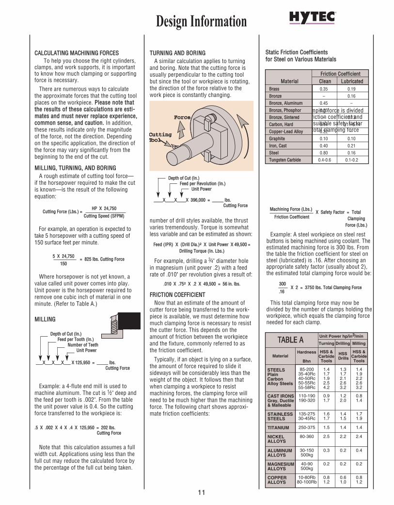
CCAALLCCUULLAATTIINNGG MMAACCHHIINNIINNGG FFOORRCCEESSTo help you choose the right cylinders,
clamps, and work supports, it is importantto know how much clamping or supportingforce is necessary.
There are numerous ways to calculate the approximate forces that the cutting toolplaces on the workpiece. PPlleeaassee nnoottee tthhaatttthhee rreessuullttss ooff tthheessee ccaallccuullaattiioonnss aarree eessttii--mmaatteess aanndd mmuusstt nneevveerr rreeppllaaccee eexxppeerriieennccee,,ccoommmmoonn sseennssee,, aanndd ccaauuttiioonn.. In addition,these results indicate only the magnitude of the force, not the direction. Dependingon the specific application, the direction ofthe force may vary significantly from thebeginning to the end of the cut.
MMIILLLLIINNGG,, TTUURRNNIINNGG,, AANNDD BBOORRIINNGGA rough estimate of cutting tool force—
if the horsepower required to make the cutis known—is the result of the followingequation:
HHPP XX 2244,,775500
CCuuttttiinngg SSppeeeedd ((SSFFPPMM))
For example, an operation is expected totake 5 horsepower with a cutting speed of150 surface feet per minute.
55 XX 2244,,775500
115500
Where horsepower is not yet known, avalue called unit power comes into play.Unit power is the horsepower required toremove one cubic inch of material in oneminute. (Refer to Table A.)
MMIILLLLIINNGG
Example: a 4-flute end mill is used tomachine aluminum. The cut is 1⁄2" deep andthe feed per tooth is .002". From the tablethe unit power value is 0.4. So the cuttingforce transferred to the workpiece is:
..55 XX ..000022 XX 44 XX ..44 XX 112255,,995500 == 220022 llbbss.. CCuuttttiinngg FFoorrccee
Note that this calculation assumes a fullwidth cut. Applications using less than thefull cut may reduce the calculated force bythe percentage of the full cut being taken.
TTUURRNNIINNGG AANNDD BBOORRIINNGGA similar calculation applies to turning
and boring. Note that the cutting force isusually perpendicular to the cutting tool but since the tool or workpiece is rotating,the direction of the force relative to thework piece is constantly changing.
Example: Boring a hole in alloy steel heattreated to 37 Rc (unit power 1.7), with adepth of cut of .060", a feed rate of .003"inches per revolution gives a result of:
..006600 XX ..000033 XX 11..77 XX 339966,,000000 == 112211 llbbss.. CCuuttttiinngg FFoorrccee
DDRRIILLLLIINNGGThe forces involved in drilling can be
separated into two distinctly different categories: thrust and torque. With the
number of drill styles available, the thrustvaries tremendously. Torque is somewhatless variable and can be estimated as shown:
FFeeeedd ((IIPPRR)) XX ((DDrriillll DDiiaa..))2 XX UUnniitt PPoowweerr XX 4499,,550000 == DDrriilllliinngg TToorrqquuee ((IInn.. LLbbss..))
For example, drilling a 3⁄4" diameter holein magnesium (unit power .2) with a feedrate of .010" per revolution gives a result of:
..001100 XX ..77552 XX ..22 XX 4499,,550000 == 5566 iinn.. llbbss..
FFRRIICCTTIIOONN CCOOEEFFFFIICCIIEENNTTNow that an estimate of the amount of
cutter force being transferred to the work-piece is available, we must determine howmuch clamping force is necessary to resistthe cutter force. This depends on theamount of friction between the workpieceand the fixture, commonly referred to asthe friction coefficient.
Typically, if an object is lying on a surface,the amount of force required to slide itsideways will be considerably less than theweight of the object. It follows then thatwhen clamping a workpiece to resistmachining forces, the clamping force willneed to be much higher than the machiningforce. The following chart shows approxi-mate friction coefficients:
The estimated clamping force is dividedby the appropriate friction coefficient andthen multiplied by a suitable safety factor to get an estimated total clamping forcerequired.
CCuuttttiinngg FFoorrccee ((LLbbss..)) ==
== 882255 llbbss.. CCuuttttiinngg FFoorrccee
DDeepptthh ooff CCuutt ((IInn..))FFeeeedd ppeerr TTooootthh ((IInn..))
NNuummbbeerr ooff TTeeeetthhUUnniitt PPoowweerr
______XX______XX______XX______ XX 112255,,995500 == __________ llbbss..CCuuttttiinngg FFoorrccee
DDeepptthh ooff CCuutt ((IInn..))FFeeeedd ppeerr RReevvoolluuttiioonn ((IInn..))
UUnniitt PPoowweerr
________XX________XX________XX 339966,,000000 == __________ llbbss..CCuuttttiinngg FFoorrccee
CAST IRONSGray, Ductile& Malleable
STAINLESSSTEELS
TITANIUM
NICKELALLOYS
ALUMINUMALLOYS
MAGNESIUMALLOYS
COPPERALLOYS
STEELSPlain CarbonAlloy Steels
85-200 1.4 1.3 1.435-40Rc 1.7 1.7 1.940-50Rc 1.9 2.1 2.250-55Rc 2.5 2.6 2.655-58Rc 4.2 3.2 3.2
110-190 0.9 1.2 0.8190-320 1.7 2.0 1.4
135-275 1.6 1.4 1.730-45Rc 1.7 1.5 1.9
250-375 1.5 1.4 1.4
80-360 2.5 2.2 2.4
30-150 0.3 0.2 0.4500kg
40-90 0.2 0.2 0.2500kg
10-80Rb 0.8 0.6 0.880-100Rb 1.2 1.0 1.2
Unit Power hp/in3/min
HSSDrills
MillingTurning Drilling
HSS &CarbideTools
HSS &CarbideTools
Hardness
BhnMaterial
TTAABBLLEE AA
SSttaattiicc FFrriiccttiioonn CCooeeffffiicciieennttss ffoorr SStteeeell oonn VVaarriioouuss MMaatteerriiaallss
MMaacchhiinniinngg FFoorrccee ((LLbbss..))
FFrriiccttiioonn CCooeeffffiicciieennttXX SSaaffeettyy FFaaccttoorr == TToottaall
CCllaammppiinnggFFoorrccee ((LLbbss..))
Example: A steel workpiece on steel restbuttons is being machined using coolant. Theestimated machining force is 300 lbs. Fromthe table the friction coefficient for steel onsteel (lubricated) is .16. After choosing anappropriate safety factor (usually about 2),the estimated total clamping force would be:
330000
..1166
This total clamping force may now be divided by the number of clamps holding theworkpiece, which equals the clamping forceneeded for each clamp.
XX 22 == 33775500 llbbss.. TToottaall CCllaammppiinngg FFoorrccee
Force
Cutting T ool
Force
FFrriiccttiioonn CCooeeffffiicciieennttMMaatteerriiaall CClleeaann LLuubbrriiccaatteedd
BBrraassss 0.35 0.19
BBrroonnzzee – 0.16
BBrroonnzzee,, AAlluummiinnuumm 0.45 –
BBrroonnzzee,, PPhhoosspphhoorr 0.35 –
BBrroonnzzee,, SSiinntteerreedd – 0.13
CCaarrbboonn,, HHaarrdd 0.14 0.11-0.14
CCooppppeerr--LLeeaadd AAllllooyy 0.22 –
GGrraapphhiittee 0.10 0.10
IIrroonn,, CCaasstt 0.40 0.21
SStteeeell 0.80 0.16
TTuunnggsstteenn CCaarrbbiiddee 0.4-0.6 0.1-0.2
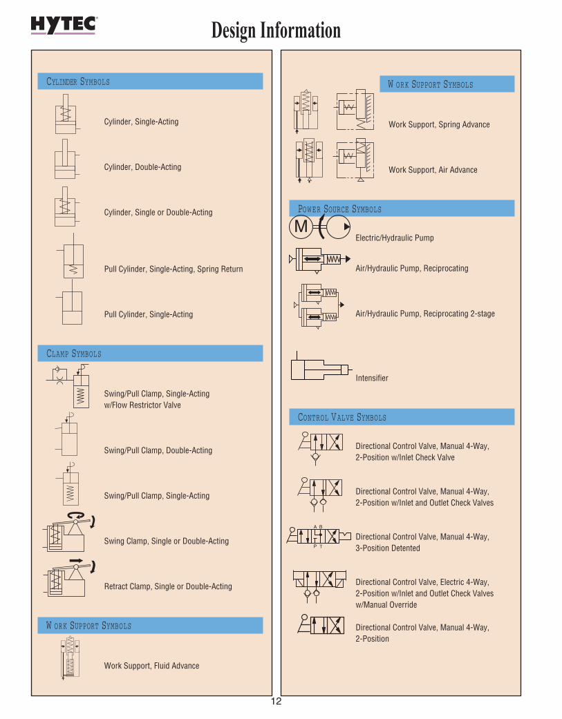
12
CYLINDER SYMBOLS
Cylinder, Single-Acting
Cylinder, Double-Acting
Cylinder, Single or Double-Acting
Pull Cylinder, Single-Acting, Spring Return
Pull Cylinder, Single-Acting
CLAMP SYMBOLS
Swing/Pull Clamp, Single-Acting w/Flow Restrictor Valve
Swing/Pull Clamp, Double-Acting
Swing/Pull Clamp, Single-Acting
Swing Clamp, Single or Double-Acting
Retract Clamp, Single or Double-Acting
W ORK SUPPORT SYMBOLS
Work Support, Fluid Advance
W ORK SUPPORT SYMBOLS
Work Support, Spring Advance
Work Support, Air Advance
POWER SOURCE SYMBOLS
Electric/Hydraulic Pump
Air/Hydraulic Pump, Reciprocating
Air/Hydraulic Pump, Reciprocating 2-stage
Intensifier
CONTROL VALVE SYMBOLS
Directional Control Valve, Manual 4-Way,2-Position w/Inlet Check Valve
Directional Control Valve, Manual 4-Way, 2-Position w/Inlet and Outlet Check Valves
Directional Control Valve, Manual 4-Way, 3-Position Detented
Directional Control Valve, Electric 4-Way,2-Position w/Inlet and Outlet Check Valves w/Manual Override
Directional Control Valve, Manual 4-Way, 2-Position
Design Information
M
A B
P T

CONTROL VALVE SYMBOLS
Pressure Sequence Valve, Adjustable w/Reverse Free-Flow Check Valve
Pressure Reducing Valve, Adjustable w/Reverse Free-Flow Check Valve w/Over-Pressure Relief Valve
Check Valve, Pilot Operated w/Filters
Flow Restrictor, Adjustable w/Reverse Free-Flow Check Valve
Flow Restrictor, Adjustable
PALLET COUPLING SYMBOLS
Manual Pallet Valve w/Gauge and Male Coupler
Manual Pallet Valve With Filters, Gauge and Coupler
ACCESSORY SYMBOLS
Hydraulic Coupler, Half-Male or Female
Hydraulic Coupler Set, Coupled
ACCESSORY SYMBOLS
Check Valve
Flow Restrictor, Fitted w/Reverse Free-FlowCheck Valve w/Filtered Orifice
Hydraulic Coupler Set, Uncoupled
Accumulator, Gas Charged
Filter
Pressure Gauge
Rotating Union, Dual Circuit
Rotating Union, Single Circuit
Pressure Switch, Adjustable
Check Valve Sub-Plate
Air Bleed Valve
Ball Valve
13
Design Information
TP
BA
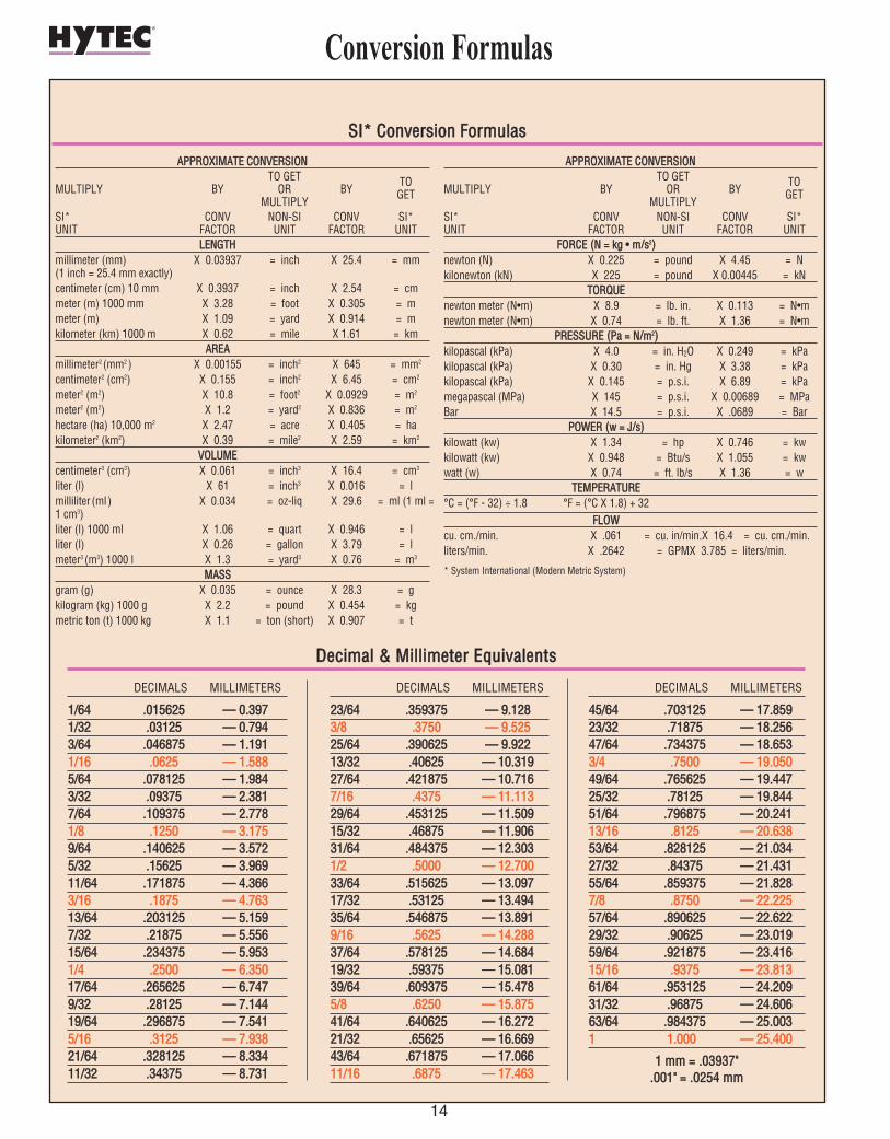
14
Conversion Formulas
AAPPPPRROOXXIIMMAATTEE CCOONNVVEERRSSIIOONNTO GET
MULTIPLY BY OR BYTO
MULTIPLY GET
SI* CONV NON-SI CONV SI* UNIT FACTOR UNIT FACTOR UNIT
LLEENNGGTTHHmillimeter (mm) X 0.03937 = inch X 25.4 = mm (1 inch = 25.4 mm exactly)centimeter (cm) 10 mm X 0.3937 = inch X 2.54 = cmmeter (m) 1000 mm X 3.28 = foot X 0.305 = mmeter (m) X 1.09 = yard X 0.914 = mkilometer (km) 1000 m X 0.62 = mile X 1.61 = km
AARREEAAmillimeter2 (mm2 ) X 0.00155 = inch2 X 645 = mm2
centimeter2 (cm2) X 0.155 = inch2 X 6.45 = cm2
meter2 (m2) X 10.8 = foot2 X 0.0929 = m2
meter2 (m2) X 1.2 = yard2 X 0.836 = m2
hectare (ha) 10,000 m2 X 2.47 = acre X 0.405 = hakilometer2 (km2) X 0.39 = mile2 X 2.59 = km2
VVOOLLUUMMEEcentimeter3 (cm3) X 0.061 = inch3 X 16.4 = cm3
liter (l) X 61 = inch3 X 0.016 = lmilliliter (ml ) X 0.034 = oz-liq X 29.6 = ml (1 ml =1 cm3)liter (l) 1000 ml X 1.06 = quart X 0.946 = lliter (l) X 0.26 = gallon X 3.79 = lmeter3 (m3) 1000 l X 1.3 = yard3 X 0.76 = m3
MMAASSSSgram (g) X 0.035 = ounce X 28.3 = gkilogram (kg) 1000 g X 2.2 = pound X 0.454 = kgmetric ton (t) 1000 kg X 1.1 = ton (short) X 0.907 = t
AAPPPPRROOXXIIMMAATTEE CCOONNVVEERRSSIIOONNTO GET
MULTIPLY BY OR BYTO
MULTIPLY GET
SI* CONV NON-SI CONV SI* UNIT FACTOR UNIT FACTOR UNIT
FFOORRCCEE ((NN == kkgg •• mm//ss22))newton (N) X 0.225 = pound X 4.45 = Nkilonewton (kN) X 225 = pound X 0.00445 = kN
TTOORRQQUUEEnewton meter (N•m) X 8.9 = lb. in. X 0.113 = N•mnewton meter (N•m) X 0.74 = lb. ft. X 1.36 = N•m
PPRREESSSSUURREE ((PPaa == NN//mm22))kilopascal (kPa) X 4.0 = in. H2O X 0.249 = kPakilopascal (kPa) X 0.30 = in. Hg X 3.38 = kPakilopascal (kPa) X 0.145 = p.s.i. X 6.89 = kPamegapascal (MPa) X 145 = p.s.i. X 0.00689 = MPaBar X 14.5 = p.s.i. X .0689 = Bar
PPOOWWEERR ((ww == JJ//ss))kilowatt (kw) X 1.34 = hp X 0.746 = kwkilowatt (kw) X 0.948 = Btu/s X 1.055 = kwwatt (w) X 0.74 = ft. lb/s X 1.36 = w
TTEEMMPPEERRAATTUURREE°C = (°F - 32) ÷ 1.8 °F = (°C X 1.8) + 32
FFLLOOWWcu. cm./min. X .061 = cu. in/min.X 16.4 = cu. cm./min.liters/min. X .2642 = GPMX 3.785 = liters/min.
* System International (Modern Metric System)
SSII** CCoonnvveerrssiioonn FFoorrmmuullaass
DECIMALS MILLIMETERS
11//6644 ..001155662255 —— 00..33997711//3322 ..0033112255 —— 00..77994433//6644 ..004466887755 —— 11..11991111//1166 ..00662255 —— 11..55888855//6644 ..007788112255 —— 11..99884433//3322 ..0099337755 —— 22..33881177//6644 ..110099337755 —— 22..77778811//88 ..11225500 —— 33..11775599//6644 ..114400662255 —— 33..55772255//3322 ..1155662255 —— 33..9966991111//6644 ..117711887755 —— 44..33666633//1166 ..11887755 —— 44..7766331133//6644 ..220033112255 —— 55..11559977//3322 ..2211887755 —— 55..5555661155//6644 ..223344337755 —— 55..99553311//44 ..22550000 —— 66..3355001177//6644 ..226655662255 —— 66..77447799//3322 ..2288112255 —— 77..1144441199//6644 ..229966887755 —— 77..55441155//1166 ..33112255 —— 77..9933882211//6644 ..332288112255 —— 88..3333441111//3322 ..3344337755 —— 88..773311
DECIMALS MILLIMETERS
2233//6644 ..335599337755 —— 99..11228833//88 ..33775500 —— 99..5522552255//6644 ..339900662255 —— 99..9922221133//3322 ..4400662255 —— 1100..3311992277//6644 ..442211887755 —— 1100..77116677//1166 ..44337755 —— 1111..1111332299//6644 ..445533112255 —— 1111..5500991155//3322 ..4466887755 —— 1111..9900663311//6644 ..448844337755 —— 1122..33003311//22 ..55000000 —— 1122..7700003333//6644 ..551155662255 —— 1133..0099771177//3322 ..5533112255 —— 1133..4499443355//6644 ..554466887755 —— 1133..88991199//1166 ..55662255 —— 1144..2288883377//6644 ..557788112255 —— 1144..6688441199//3322 ..5599337755 —— 1155..0088113399//6644 ..660099337755 —— 1155..44778855//88 ..66225500 —— 1155..8877554411//6644 ..664400662255 —— 1166..2277222211//3322 ..6655662255 —— 1166..6666994433//6644 ..667711887755 —— 1177..0066661111//1166 ..66887755 —— 1177..446633
DECIMALS MILLIMETERS
4455//6644 ..770033112255 —— 1177..8855992233//3322 ..7711887755 —— 1188..2255664477//6644 ..773344337755 —— 1188..66553333//44 ..77550000 —— 1199..0055004499//6644 ..776655662255 —— 1199..4444772255//3322 ..7788112255 —— 1199..8844445511//6644 ..779966887755 —— 2200..2244111133//1166 ..88112255 —— 2200..6633885533//6644 ..882288112255 —— 2211..0033442277//3322 ..8844337755 —— 2211..4433115555//6644 ..885599337755 —— 2211..88228877//88 ..88775500 —— 2222..2222555577//6644 ..889900662255 —— 2222..6622222299//3322 ..9900662255 —— 2233..0011995599//6644 ..992211887755 —— 2233..4411661155//1166 ..99337755 —— 2233..8811336611//6644 ..995533112255 —— 2244..2200993311//3322 ..9966887755 —— 2244..6600666633//6644 ..998844337755 —— 2255..00003311 11..000000 —— 2255..440000
11 mmmm == ..0033993377""..000011"" == ..00225544 mmmm
DDeecciimmaall && MMiilllliimmeetteerr EEqquuiivvaalleennttss
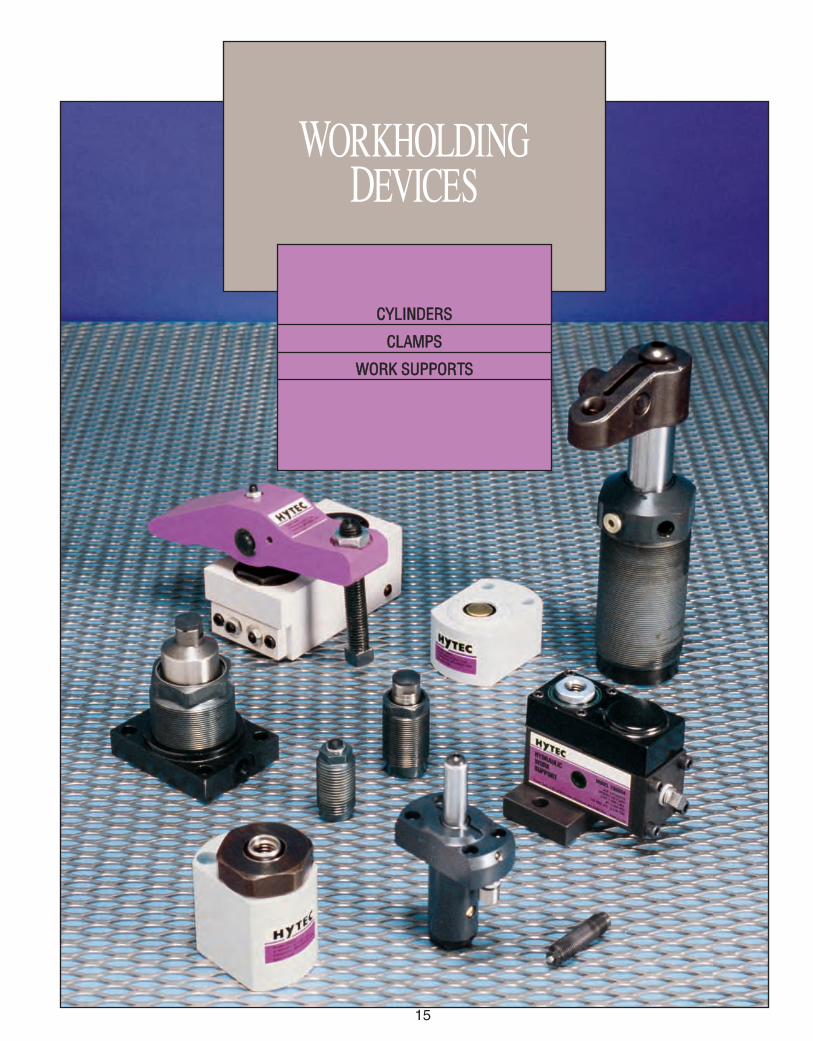
15
WORKHOLDINGDEVICES
CCYYLLIINNDDEERRSS
CCLLAAMMPPSS
WWOORRKK SSUUPPPPOORRTTSS
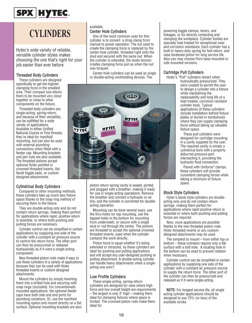
Hytec’s wide variety of reliable,versatile cylinder styles makeschoosing the one that’s right for yourjob easier than ever before.
TThhrreeaaddeedd BBooddyy CCyylliinnddeerrssThese cylinders are designed
specifically to get the highestclamping force in the smallestarea. Their compact size allowsthem to be mounted very closetogether or close to othercomponents on the fixture.
Threaded body cylinders aresingle-acting, spring-return,and because of their versatility,can be outfitted for a widevariety of applications.Available in either UnifiedNational Coarse or Fine threads,they’re ideal for manifoldmounting, but can also be usedwith external plumbingconnections when fitted with afeeder cap. Mounting bracketsand jam nuts are also available.The threaded pistons acceptoptional Hytec pointed orcrowned threaded inserts, flatfaced toggle pads, or customdesigned attachments.
CCyylliinnddrriiccaall BBooddyy CCyylliinnddeerrssCompared to other mounting methods,
these cylinders take up much less fixturespace thanks to the snap ring method ofsecuring them to the fixture.
They are double-acting only and do notcontain return springs, making them perfectfor applications where rapid, positive returnis essential, or where both pushing andpulling forces are necessary.
Cylinder control can be simplified in certainapplications by supplying one side of thecylinder with a constant air pressure sourceto control the return force. The other portcan then be pressurized or releasedhydraulically as if it were a single-actingcomponent.
New threaded piston rods make it easy touse these cylinders in a variety of applicationsbecause they can be used with Hytecthreaded inserts or custom designedattachments.
Mount the cylinders by simply insertingthem into a drilled hole and securing withsnap rings (included). For conventionallymounted applications, the optional feedercaps have both side and end ports forplumbing variations. Or, use the manifoldmounting option and mount directly on a flatsurface. Optional mounting brackets are also
available.CCeenntteerr HHoollee CCyylliinnddeerrss
One of the most common uses for thiscylinder is to convert a strap clamp frommanual to power operation. The nut used tocreate the clamping force is replaced by thecenter-hole cylinder, threaded right onto thestud and secured with the same nut. Whenthe cylinder is extended, the studs tensioncreates clamping force just as when the nutwas torqued.
Center-hole cylinders can be used as singleor double-acting workholding devices. The
piston return spring cavity is sealed, ported,and plugged with a breather, making it readyfor use in single-acting operations. Removethe breather and connect a hydraulic or airline, and the cylinder is converted for double-acting operation.
Mounting can be done several ways: usethe thru-holes for top mounting, use thetapped holes in the bottom for mountingfrom underneath, or secure with a singlestud or rod through the center. The pistonsare threaded to accept the optional crownedthreaded inserts, used when the cylindercontacts the work directly.
Piston force is equal whether it’s beingextended or retracted, so these cylinders areideal for pushing and pulling applicationsand will accept any user-designed pushing orpulling attachment. A double-acting cylindercan handle heavy attachments when a single-acting one won’t.
LLooww PPrrooffiillee CCyylliinnddeerrssThese single-acting, spring-return
cylinders are designed for uses where highforce and low overall height are requirements– the largest is only 2" high – making themideal for clamping fixtures where space islimited. The crowned piston rods make themideal for
powering toggle clamps, levers, andlinkages, or for directly contacting andclamping the workpiece. Cylinder bodies arespecially heat treated for exceptional wearand corrosion resistance. Each cylinder has abuilt-in heavy-duty spring for fast return, andcase hardened piston for long service life.Also you may choose from base mounted orside mounted versions.
CCaarrttrriiddggee PPuullll CCyylliinnddeerrssHytec’s “Pull” cylinders retract when
hydraulically pressurized. Theywere created to permit the userto design a cylinder into a fixturewhile maintaining thereplaceability and long life of aheat treated, corrosion resistantcylinder body. Typicalapplications of these cylindersinclude installation behind fixtureplates or buried in tombstoneswhere they can supply clampingforce without taking up valuablefixture space.
These pull cylinders weredesigned for cartridge mountingin a cavity supplied by the user.The required cavity is simply acylindrical bore with a properlydeburred pressure portintersecting it, providing thehydraulic fluid connection.
Paired with Uniforce® clamps,these cylinders will provideconsistent clamping forces whiletaking a minimum of fixturespace.
BBlloocckk SSttyyllee CCyylliinnddeerrssHytec’s block style cylinders are double-
acting only and do not contain returnsprings, making them perfect forapplications where rapid positive return isessential or where both pushing and pullingforces are required.
Now, more applications are possiblethanks to the new threaded piston rods.Hytec threaded inserts or any custom-designed attachments may be used.
The simplest to mount – from either top orbottom – these cylinders require only a flatsurface with a bolt hole. A locating hole inthe bottom can be used to prevent rotationwhen necessary.
Cylinder control can be simplified in certainapplications by supplying one side of thecylinder with a constant air pressure sourceto supply the return force. The other port ofthe cylinder can then be pressurized andreleased as if it were single-acting.
NNOOTTEE:: For longest service life, all singleacting cylinder applications should bedesigned to use 75% (or less) of theavailable stroke.
Cylin
ders
16
CYLINDERS

TThhrreeaaddeedd BBooddyy CCyylliinnddeerrss
17
NOTE: * Based on 5,000 psi max. operating pressure.
Cylinder Nos. 100064, 100065 100156, 100157 Cylinder Nos. 100139 100148,100159,100166 Cylinder Nos. 100167, 100153 100149, 100171 Cylinder Nos. 100172, 100173
0 1000 2000 3000 4000 5000
1750
1500
1250
1000
750
500
250
0
Hydraulic Pressure (PSI)
Force (Lbs.)
Performance
K
FB STROKE
H
JE
D
C
GA
L
100149
100153
100172
Threaded Body Cylinders
Fine Thd. Body Cyls. Coarse Thd. Body Cyls. Specifications Dimensions (In Inches)
Cat.No.
AThread
Size
Cat.No.
AThread
Size
*Force(Lbs.)
Stroke(In.)
Eff. Area(Sq. in.)
Oil Cap.(Cu. in.)
B C DThd.
Depth
EHex.
1001561⁄2-20 UNF
1000641⁄2-13 UNC 245
.250.049
.012 1.636 1.568— .312
100157 100065 .024 2.042 1.974.156
F
.399
GDia.
.156
HDia.
—
JThread
Size
.375
KRadius
.062
LDia.
1001595⁄8-18 UNF
1001395⁄8-11 UNC 550
.250.110
.027 1.655 1.625
.438
.438 .502 .250
10-32 UNF
—
.094100166 100148
.500.055 2.225 2.187
1001673⁄4-16 UNF
1001493⁄4-10 UNC 750 .150
.075 1.756 1.718.531
.187
.615 .300 .125100171 100153 1.000 .150 2.475 2.437
1001721-12 UNF
—— 1535
.500.307
.153 2.005 1.937.500 .750 .875 .500 5⁄16-24 UNF .187
100173 — 1.000 .307 2.629 2.562
.500
Our most versatile cylinder style, thesethreaded body cylinders are single-acting,spring-return, and can be outfitted for a widevariety of applications. Available in eitherUnified National Coarse or Fine threads,they’re ideal for manifold mounting, but canalso be used for external plumbingconnections when fitted with a feeder cap.Mounting brackets and jam nuts can bespecified for added mounting versatility. Thethreaded pistons will accept optional Hytec pointed orcrowned threaded inserts, flat faced togglepads, or you can custom design your ownattachments. These cylinders should alwaysbe used with a threaded insert to preventdamage to the workpiece and the cylinder.Features:
• Manifold or conventional mounting• Heavy duty return springs• Optional jam nuts, feeder caps and
mounting brackets• Threaded, plated piston rod• Fine or coarse threads• “O” ring seal included• 100% corrosion resistant• Single-acting• Power-Tech treated body for long wear and
corrosion resistanceNNoottee:: See page 23 for threaded inserts.
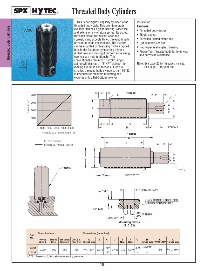
TThhrree
aaddeedd
BBoodd
yy CCyy
lliinnddee
rrss
18
Threaded Body Cylinders
100208
Eff. Area(Sq. In.)
Oil Cap.(Cu. In.)
*Force(Lbs.)
Dimensions (In Inches)
B C D EDia.
FDia.
G HThread Size
KThread Depth
NOTE: *Based on 5,000 psi max. operating pressure.
AThread Size
LThread Size
1002083,927 1.000 .785 .785 15⁄16-16UN 3.312
.7502.438 .750 1.210
.531.375 5⁄16-24 UNF
Stroke(In.)
Cat. No.
Specifications
A
C D B STROKE
G
F
H K
E
L
0 1000 2000 3000 4000 5000
4000
3000
2000
1000
Hydraulic Pressure (PSI)
Force (Lbs.)
Performance
Cylinder No. 100208, 110132
110132 .250 – –
100208
110132
A
C
D
B
F
K
E
L
1.250 Hex
1-5/16-16UN-2B
ONLY CONCENTRIC TOOL MARKS PERMISSIBLE
.125
.500 Ø THRU1.245 MIN.
.350 MIN.
.577 MIN.
A
C
D
B
F
K
E
L
1.250 Hex
1-5/16-16UN-2B
ONLY CONCENTRIC TOOL MARKS PERMISSIBLE
.125
.500 Ø THRU1.245 MIN.
.350 MIN.
.577 MIN.
110132
Mounting Cavity(110132)
1⁄8 NPTF
This is our highest capacity cylinder in thethreaded body style. This premium gradecylinder includes a gland bearing, wiper seal,and extension style return spring. Its plated,threaded piston rod resists wear andcorrosion and accepts Hytec threaded insertsor custom made attachments. The 100208can be mounted by threading it into a tappedhole in the fixture or by inserting it into adrilled hole and locking it on both sides usingtwo hex jam nuts (optional). Thisconventionally mounted 1" stroke, single-acting cylinder has a 1/8" NPT side port formaking hydraulic connections. Like oursmaller, threaded body cylinders, the 110132is intended for manifold mounting andrequires only a flat-bottom hole for
installation.Features:• Threaded body design• Single-acting• Threaded, plated piston rod• Optional hex jam nut• Rod wiper seal in gland bearing• Power-Tech™ treated body for long wear
and corrosion resistance
NNoottee:: See page 23 for threaded inserts. See page 19 for jam nut.

Threaded Body Cylinders
10391 1⁄2-13UNC .750 .312
10390 1⁄2-20UNF .750 .312
10395 5⁄8-11UNC .938 .375
10394 5⁄8-18UNF .938 .375
10397 3⁄4-10UNC 1.125 .422
10396 3⁄4-16UNF 1.125 .422
201029 1-12UNF 1.500 .562
216207 1 5⁄16-16UN 2.000 .719
AThread Size
BHex.
C
Dimensions (In Inches)
JAM NUTS
Cat. No.
NOTE: 5,000 psi max. operating pressure.
Foot Mounting Bracket
Feeder CapJam Nut
M
L
K
J
HG
FE
DD
C
B
A
C B
A
FEEDER CAPS
SAE Ports NPT Ports Dimensions (In Inches)
Cat. No.
AThread
Size
Cat. No.
BThread
Size
CHex.
D E
100927
7⁄16-20UNFSAE-4
500097 1⁄2-20UNF0.750 1.200 0.437
100928 500100 1⁄2-13UNC
100929 500098 5⁄8-18UNF0.875
1.390 0.500
100930 500101 5⁄8-11UNC
100931 500099 3⁄4-16UNF1.000
100932 500102 3⁄4-10UNC
100933 500103 1-12UNF 1.250
AThread
Size
1⁄8-NTPF
1⁄4-NTPF
////Cat. No.
Dimensions (In Inches)A B C D
400000 1.875 1.750 .938.625
4000012.000
1.8751.000
400002 2.000 .656
400003 2.500 2.500 1.250 .812 .375
.344
.312
.250
E
.750
.687
.562
.455
F
2.000
1.687
1.625
1.312
G
1.182
1.062
.938
.812
H
.375
.312
.350
J
1-12 UNF
3⁄4-10 UNC
5⁄8-11 UNC
1⁄2-13 UNC
KThread
Size
.422
.359
.281
LDia.
.598
.504
.410
Dia.
M
.343
.406
.218
Depth
FOOT MOUNTING BRACKETS
CD
B A
E
19
TThhrreeaaddeedd BBooddyy CCyylliinnddeerrss
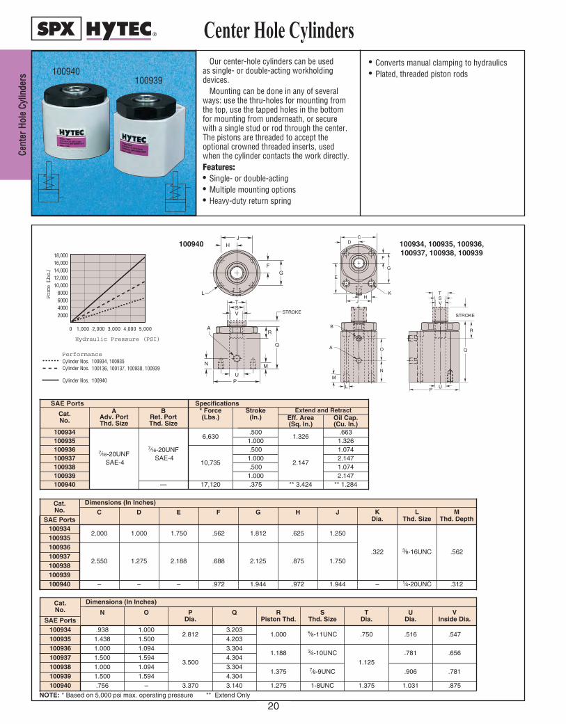
CCeenntt
eerr HH
oollee
CCyylliinn
ddeerrss
20
Center Hole Cylinders
0 1,000 2,000 3,000 4,000 5,000
18,00016,00014,00012,00010,000
8000600040002000
Hydraulic Pressure (PSI)
PerformanceCylinder Nos. 100934, 100935Cylinder Nos. 100136, 100137, 100938, 100939
Cylinder Nos. 100940
Force (Lbs.)
NOTE: * Based on 5,000 psi max. operating pressure ** Extend Only
F
CD
G
E
HK
J
UP
TSV
STROKE
Q
RB
A
N
O
M
L
STROKE
R
Q
A
U P
N
T S V
M
F G
J H
L
100940 100934, 100935, 100936,100937, 100938, 100939
SAE Ports Specifications
Cat. No.
AAdv. Port Thd. Size
BRet. Port Thd. Size
* Force(Lbs.)
Stroke (In.)
Extend and RetractEff. Area (Sq. In.)
Oil Cap. (Cu. In.)
100934
7⁄16-20UNFSAE-4
7⁄16-20UNFSAE-4
6,630.500
1.326.663
100935 1.000 1.326100936
10,735
.500
2.147
1.074100937 1.000 2.147100938 .500 1.074100939 1.000 2.147100940 17,120 .375 ** 3.424 ** 1.284
Cat. No. C D E F G H J K
Dia.L
Thd. SizeM
Thd. DepthSAE Ports100934
2.000 1.000 1.750 .562 1.812 .625 1.250
.322 3⁄8-16UNC .562
100935100936
2.550 1.275 2.188 .688 2.125 .875 1.750100937100938100939100940 – – – .972 1.944 .972 1.944 – 1⁄4-20UNC .312
Cat. No.
Dimensions (In Inches)
N O PDia.
Q RPiston Thd.
SThd. Size
T Dia.
U Dia.
V Inside Dia.SAE Ports
100934 .938 1.0002.812
3.2031.000 5⁄8-11UNC .750 .516 .547
100935 1.438 1.500 4.203100936 1.000 1.094
3.500
3.3041.188 3⁄4-10UNC
1.125.781 .656
100937 1.500 1.594 4.304100938 1.000 1.094 3.304
1.375 7⁄8-9UNC .906 .781100939 1.500 1.594 4.304100940 .756 – 3.370 3.140 1.275 1-8UNC 1.375 1.031 .875
100939100940
Dimensions (In Inches)
—
Our center-hole cylinders can be used as single- or double-acting workholdingdevices.
Mounting can be done in any of severalways: use the thru-holes for mounting fromthe top, use the tapped holes in the bottomfor mounting from underneath, or securewith a single stud or rod through the center.The pistons are threaded to accept theoptional crowned threaded inserts, usedwhen the cylinder contacts the work directly. Features:• Single- or double-acting• Multiple mounting options• Heavy-duty return spring
• Converts manual clamping to hydraulics• Plated, threaded piston rods

21
These single-acting, spring-returncylinders are designed for applications wherehigh force and low overall height arerequirements. Ideal for clamping fixtureswhere space is limited. The crowned pistonmakes them perfect for powering strapclamps, linkages or for direct contact withthe workpiece. Cylinder bodies are heattreated using a special process forexceptional wear and corrosion resistance.Three sizes to choose from – the largestbeing only 2" high – with maximum forcesranging from 4,920 lbs. to 22,150 lbs. Eachcylinder has a built-in heavy-duty spring forfast return, and case hardened piston forlong service life.
The 100855 and 100925 use the samerugged design with different mounting
options. Designed for side mounting, fourgrade 8 mounting screws can easily resistthe force of the clamp so no additional stopsor clamp mounting structure is necessary.Features:• Low overall height• Bronze plated piston• Piston rod wiper seal• Heavy-duty return spring• Heat treated and plated cylinder body• Single-acting• Power-Tech™ treated body for long wear
and corrosion resistance
Low Profile Cylinders
100201
100925
0 1000 2000 3000 4000 5000
24,000
20,000
16,000
12,000
8000
4000
Hydraulic Pressure (PSI)
Force (Lbs.)
Performance
Cylinder No. 100203
Cylinder No. 100201
Cylinder No. 100202
E
B
A
H
D
J
KF
J
STROKE
L
M
N
OG
C
C
B
A
D
H
STROKE
F
G
E
J
D
K
L
Performance
Cylinder No. 100855
1000 2000 3000 4000 5000
5000
4000
3000
2000
1000
0
Hydraulic Pressure (PSI)
Force (Lbs.)
100855, 100925100201, 100202, 100203
Cat. No.
Specifications Dimensions (In Inches)
*Force(Lbs.)
Stroke(In.)
Eff. Area(Sq. In.)
Oil Cap. A B C D E F G H J K L M N
1008554,920
.562.994
.6202.875 1.625 .812 .937 .625
.250.281 1⁄4 NPTF
2.0621.500 .282
– –
100925 .875 .870 .250 3.002 1⁄4 NPTF .550
NOTE: * Based on 5,000 psi max. operating pressure.
100203 4,920 .562 .994 .62 2.562 1.635 1.667 .812 1.750 .625 1.000 .562 .219 0° .770 1.150
100201 11,180.437
2.236 1.00 3.250 2.190 1.750 .375 1.095 1.985 .750 1.312 .718 .2815° .630
1⁄4 NPTF 1.250
100202 22,150 4.430 2.00 4.000 3.000 2.000 1.500 2.270 1.125 1.560 .968 .406 1.280
ADia.
*Force(Lbs.)
LPort
Angle
JHGDia.
FEDC M NThread Size
ORadius
KDia.
Cat.No. BStroke
(In.)Eff.
Area(Sq. In.)
Oil Cap.(Cu. In.)
NOTE: *Based on 5,000 psi max. operating pressure.
Specifications Dimensions (In Inches)
LLooww PPrrooffiillee CCyylliinnddeerrss
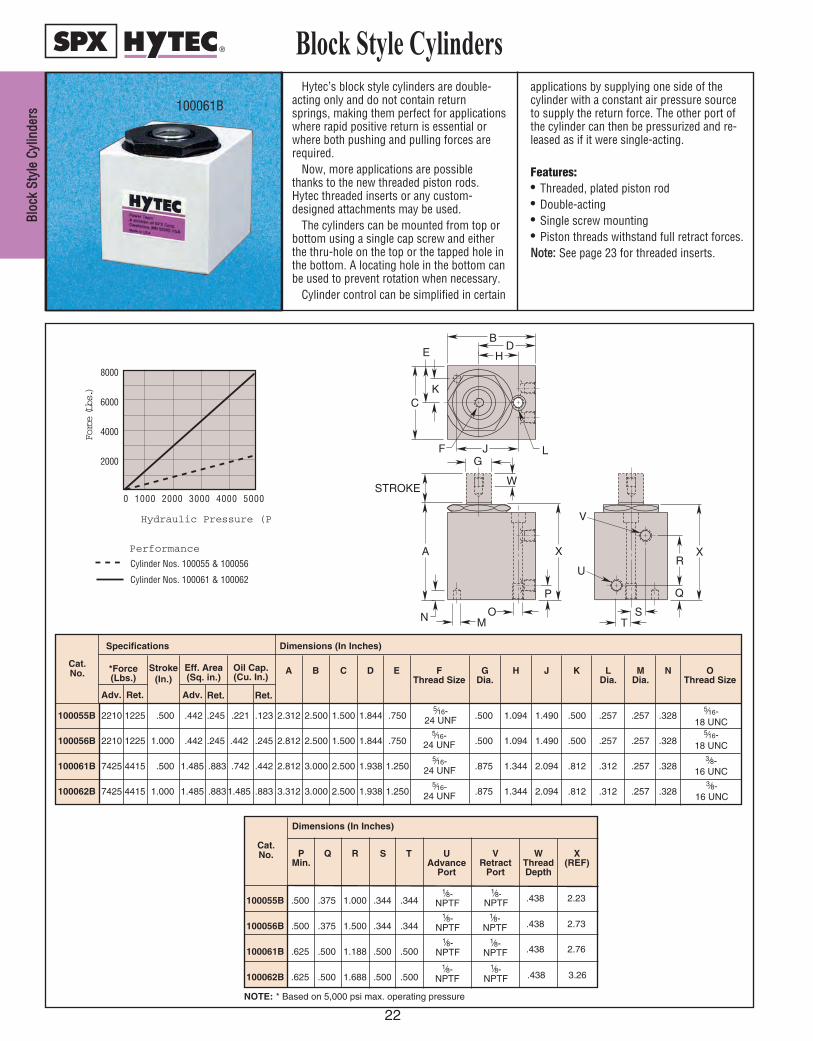
BBlloocc
kk SStt
yyllee
CCyylliinn
ddeerrss
22
Block Style Cylinders
0 1000 2000 3000 4000 5000
8000
6000
4000
2000
Hydraulic Pressure (PSI)
Force (Lbs.)
Performance
Cylinder Nos. 100055 & 100056
Cylinder Nos. 100061 & 100062
100055B 2210 1225 .500 .442 .245 .221 .123 2.312 2.500 1.500 1.844 .750 .500 1.094 1.490 .500 .257 .257 .328
100056B 2210 1225 1.000 .442 .245 .442 .245 2.812 2.500 1.500 1.844 .750 .500 1.094 1.490 .500 .257 .257 .328
100061B 7425 4415 .500 1.485 .883 .742 .442 2.812 3.000 2.500 1.938 1.250 .875 1.344 2.094 .812 .312 .257 .328
100062B 7425 4415 1.000 1.485 .8831.485 .883 3.312 3.000 2.500 1.938 1.250 .875 1.344 2.094 .812 .312 .257 .3283⁄8-
16 UNC
100055B .500 .375 1.000 .344 .344
100056B .500 .375 1.500 .344 .344
100061B .625 .500 1.188 .500 .500
100062B .625 .500 1.688 .500 .500
NOTE: * Based on 5,000 psi max. operating pressure
Dimensions (In Inches)
1⁄8-NPTF
1⁄8-NPTF
1⁄8-NPTF
1⁄8-NPTF
1⁄8-NPTF
1⁄8-NPTF
1⁄8-NPTF
1⁄8-NPTF
Cat. No.
.438
.438
.438
.438
2.23
2.73
3.26
2.76
UAdvance
Port
R S TPMin.
Q VRetract
Port
WThreadDepth
X(REF)
5⁄16-24 UNF
5⁄16-24 UNF
3⁄8-16 UNC
Adv. Ret. Adv. Ret. Ret.
Eff. Area(Sq. in.)
Oil Cap. (Cu. In.)
Stroke(In.)
Specifications
5⁄16-18 UNC
5⁄16-18 UNC
5⁄16-24 UNF
5⁄16-24 UNF
Dimensions (In Inches)
Cat. No. *Force
(Lbs.)L
Dia.F
Thread SizeG
Dia.H J KEDCBA M
Dia.N O
Thread Size
Hytec’s block style cylinders are double-acting only and do not contain returnsprings, making them perfect for applicationswhere rapid positive return is essential orwhere both pushing and pulling forces arerequired.
Now, more applications are possiblethanks to the new threaded piston rods.Hytec threaded inserts or any custom-designed attachments may be used.
The cylinders can be mounted from top orbottom using a single cap screw and eitherthe thru-hole on the top or the tapped hole inthe bottom. A locating hole in the bottom canbe used to prevent rotation when necessary.
Cylinder control can be simplified in certain
applications by supplying one side of thecylinder with a constant air pressure sourceto supply the return force. The other port ofthe cylinder can then be pressurized and re-leased as if it were single-acting.
Features:• Threaded, plated piston rod• Double-acting• Single screw mounting• Piston threads withstand full retract forces.NNoottee:: See page 23 for threaded inserts.
CK
EB
DH
F LJ
N
A
STROKE
G
W
MO
P
TS
Q
R
V
U
X X
100061B
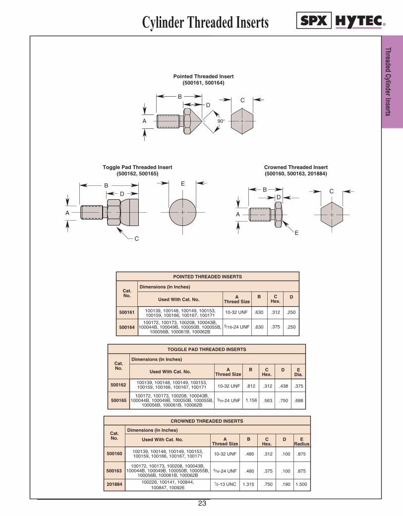
TThhrreeaaddeedd CCyylliinnddeerr IInnsseerrttss
23
Cylinder Threaded Inserts
100139, 100148, 100149, 100153,100159, 100166, 100167, 100171
5/16-24 UNF .630 .250
100139, 100148, 100149, 100153,100159, 100166, 100167, 100171
Dimensions (In Inches)
10-32 UNF .480 .312 .100 .875
5⁄16-24 UNF .480 .375 .100 .875
1⁄2-13 UNC 1.315 .750 .190 1.500
CROWNED THREADED INSERTS
100172, 100173, 100208, 100043B,100044B, 100049B, 100050B, 100055B,
100056B, 100061B, 100062B
100139, 100148, 100149, 100153,100159, 100166, 100167, 100171
TOGGLE PAD THREADED INSERTS
500160
500163
201884
10-32 UNF .312 .438 .375
5⁄16-24 UNF .563 .750 .688
500162
Cat. No. Used With Cat. No. B C
Hex.DA
Thread Size
Dimensions (In Inches)Cat. No.
Used With Cat. No. BAThread Size
EDia.
DCHex.
500165 1.156
.812
100172, 100173, 100208, 100043B,100044B, 100049B, 100050B, 100055B,
100056B, 100061B, 100062B
100226, 100141, 100844, 100847, 100926
500161 10-32 UNF .630 .250
Dimensions (In Inches)Cat. No.
POINTED THREADED INSERTS
Used With Cat. No. B DC
Hex.A
Thread Size
.312
.375100172, 100173, 100208, 100043B,
100044B, 100049B, 100050B, 100055B,100056B, 100061B, 100062B
500164
ERadius
Crowned Threaded Insert(500160, 500163, 201884)
Pointed Threaded Insert(500161, 500164)
B D
A
E
C
B D
A
C
90 °
B D
A
E
C
Toggle Pad Threaded Insert(500162, 500165)

CCaarrtt
rriiddggee
PPuull
ll CCyyll
iinnddee
rrss
24
Cartridge Pull Cylinders
Cat. No.
100866
100867
100880
Specifications Dimensions (In Inches)
5,215
1,740
5,215
*Force(Lbs.)
.312
Stroke(in.)
1.043
.348
Eff. Area(Sq. In.)
2.312
1.902
A
1.750
1.500
B
1.875
–––
C
.750
.750
DDia.
1.125
–––
EDia.
2.000
1.500
FDia.
Size
3⁄8-16 UNC
Depth
.500
––– –––
GThread
.325
.108
1.043 2.312 1.750 1.875 .750 1.125
–––
–––
HThread Size
1⁄2-13 UNC
–––
–––
J
.7502.000.325
Oil Cap.(Cu. In.)
Note: * Based on 5,000 psi max. operating pressure.
0 1000 2000 3000 4000 5000
6000
5000
4000
3000
2000
1000
FFoorrcc
ee ((llbb
ss..))
HHyyddrraauulliicc PPrreessssuurree ((PPSSII))
Performance
Cylinder Nos. 100866, 100880
Cylinder No. 100867
100880
F
STROKE
A
G
E D
G
C B
J H
D
B
F
A
STROKE
100866
100867
100866100880
100867
These "Pull" cylinders retract whenhydraulically pressurized. They were createdto permit the user to design a cylinder into afixture while maintaining the replaceabilityand long life of a heat treated, corrosionresistant cylinder body. Typical applicationsof these cylinders include installation behindfixture plates or buried in tombstones wherethey can supply clamping force withouttaking up valuable fixture space.
These pull cylinders were designed forcartridge mounting in a cavity supplied bythe user. The required cavity is simply acylindrical bore with a properly deburredpressure port intersecting it, providing thehydraulic fluid connection. They are forsingle acting systems only where the force
for cylinder return (extension) is suppliedmanually or through a spring designed intothe application by the user. A return springthat can be built into the application isavailable. (No. 251549 Order Separately)Features:• Compact design• Manifold mounting eliminates tubing• Threaded, plated piston rod• Power-Tech™ treated body for long wear
and corrosion resistance• 5,000 psi maximum pressure rate• Rod wiper to exclude contaminants• Single-Acting

WWoorrkkhhoollddiinngg DD
eevviicceess
25
Cartridge Pull Cylinder Installation
ADia.
B Cylinder Body
Cavity
CDia.
DDia.
E Chfr. / Rad.
Max.
†F G *HMin.
*JMax.
100866 2.0002.003
1.7551.765
1.7501.135
.744
.754.065
.080
.100.760.790
.485 1.020
100867 1.5001.503
1.5001.510
1.250.780 .510 .970
100880 2.0002.003
1.7551.765
1.7501.135 .485 1.020
Cat. No.
Cavity Dimensions Oil Passage Location
* Tolerance zone for blended oil passage hole. Tolerance zone does not allow any up and down motion of cylinder body.† Chamfer to be located at end of bore “A” from which the cylinder will be assembled.
MMOOUUNNTTIINNGG CCAAVVIITTYY
C
D
G
E
BF
JH
65A
20°
Blend on passage hole muststay in tolerance zone. Edgesof hole must be blended toavoid cutting o-ring.
Optional(Return spring cavityfor optional returnspring part #251549)
Note: Required thicknesswill vary due to fixturematerial used and hydraulicpressure setting.
Blend Corner(.080 R.Ref.)
Vent(Recommended with orwithout return spring)
100866–100867–100880INSTALLATION IDEAS

UUnnii
ffoorrcc
ee® ®HH
yyddrraa
uulliicc
CCllaa
mmpp
26
0
6000
5000
4000
3000
2000
1000
50000 4000300020001000Hydraulic Pressure (PSI)
Clamping Force (Lbs.) (Approximate)
110068 110067
110065110066
110063
110061110062
110059110060
110064
Performance110059 — 110068
JH
CSTROKE
BA
E
M
L K
GF
D
110066
Clamp &Cylinder
AssemblyCat. No.
Clamp Assembly Specifications Cylinder Specifications Cylinder Dimensions (In Inches)OperatingPressure
Max.(psi)
HoldingForce Max.
(Lbs.)
ClampSpread
Max.
Stroke(In.)
Eff. Area(Sq. in.)
Oil Cap.(Cu. in.)
A B C D EPiston Thread
Size Depth
110059 5,000290 .565 .123
.137 .0171.115 1.210
.373 .8108-32 UNC .320
110060 2,500.353
.043
.560
1.185110061 5,000
1,500 .830
.178
.063
1.240
1.3251⁄4-20 UNC .375
110062 2,500.537 .096 1.417 1.309
110063 5,0002,000 1.120 5⁄16-18 UNC .470
110064 2,5001.042 .185 1.365 1.470 .748 1.748
110065 5,0003,500 1.650 1⁄2-13 UNC .500
110066 2,500
.2881.802 .519 1.490
1.605.873 2.123
110067 5,0006,000 2.175
1.6905⁄8-11 UNC .625
110068 2,500 3.542 1.020 1.615 2.000 1.059 2.873
Clamp &Cylinder
AssemblyCat. No.
Uniforce Clamp Dimensions (In Inches)
110062
110064
110066
110067
UniforceClamp(only)
Cat. No.
F G H J KCap Screw
L MC’BoreDepthThd. Size Length
110059.575 .220 .410 .485 8-32 UNC .625 .625 .165 500184
110060
110061.790 .375 .635 .735 1⁄4-20 UNC .875 .940 .255 500185
1100631.090 .500 .820 .980 5⁄16-18 UNC 1.250 1.250 .310 500186
1100651.590 .750 1.215 1.470 1⁄2-13 UNC 2.000 1.875 .510 500187
2.090 1.000 1.625 1.960 5⁄8-11 UNC 2.500 2.500 .625 500188
Uniforce® Hydraulic Clamp
110068
These clamps are a combination of Mitee-Bite®
Products Uniforce® Clamp and Hytec’s cartridge pullcylinders. Two pull cylinders are offered to powereach of five of the most popular Uniforce clamps.One will create the force necessary to achieve theclamp’s rated force at 5,000 psi hydraulic pressure.The other powers the clamp to its maximum ratingat only 2,500 psi. This allows the efficient use ofthese clamps in lower pressure systems however,nneevveerr eexxcceeeedd tthhee mmaaxxiimmuumm pprreessssuurree rraattiinngg of theclamp/cylinder assembly.
The pull cylinders are designed for cartridgemounting in a cavity supplied by the fixture builder.The required cavity is simply a cylindrical bore witha properly deburred pressure port intersecting it,providing the fluid connection. Where possible, pinsinserted in the back of the piston are provided.
These pins can be guided by holes drilled in thesub-plate to prevent cylinder rotation whenadjustments are made. A breather hole shouldalways be provided and may be combined with thepin holes where appropriate.
An external stop prevents over-travel of the clampif actuated without a workpiece in place.Features:• Minimal space requirements• Reduces repetitive motion injuries• 5,000 psi and 2,500 psi max. versions• Cylinders require no additional fixture space• Rod wiper excludes contaminants• Plating & Power-Tech™ processes resist corrosion• Single-acting, spring returnMitee-Bite and Uniforce are registered trademarksof Mitee-Bite Products Company.
110066U.S. Patent No. 6,019,357

UUnniiffoorrccee
® ®CCllaamm
pp IInnssttaallllaattiioonn
27
Uniforce® Clamp Installation
Cat.No.
Cavity Dimensions (In Inches)
ADia.
BCyl. Body
LengthMax.
CDia.
110059.812.815 1.120
1.130
.387
.577
1100601.1871.190
.572
.911110061
1.2451.255
1100621.3121.315
.5721.000
110063
†D
.125
.145
Oil Passage Location(In Inches)
EMin.
.475
.427
.437
.476
FMax.
.728
.710
.787
.734
1100641.7501.753
1.3701.380
.7601.437
.819110065
.531
1100662.1252.128
1.4951.505
.8851.812
.526.943
110067
1100682.8752.878
1.6201.630
1.0742.500
1.001
500184 — 500188 Application Chart
A
B
Cat.No.
Dimensions (In Inches)
AGrooveWidth
BWorkpiece
Spacing
500184 .440 .500
500185 .665 .750
500186 .850 1.000
500187 1.245 1.500
500188 1.655 2.000
Note: Groove “A” is recommended to maintain clamp orientation.
110059 — 110068Cavity Dimensions
PIN HOLE)(FOR BLINDG
L
K K
Required thickness will vary due tofixture material used. Must resistmaximum cylinder force.
A
FE
C
B
20°
Edges of hole must be blendedto avoid cutting O-ring. Blend onpassage hole must stay intolerance zone.
(.080 R. Ref.)Blend Corner
D
J
H
Required thickness will vary due tofixture material used. Must resistmaximum cylinder force.Ø .015 M Ø .015 M
65
KDia.
—
.270
.280
J
—
1.100
1.570
Cavity Dimensions (In Inches)
GMin.
—
.510
.650
H
—
.550
.785
*LVent
Dia. Min.
.125
Note: * Cavity must be vented† Chamfer to be located at end of bore “A” from which the cylinder will be assembled.
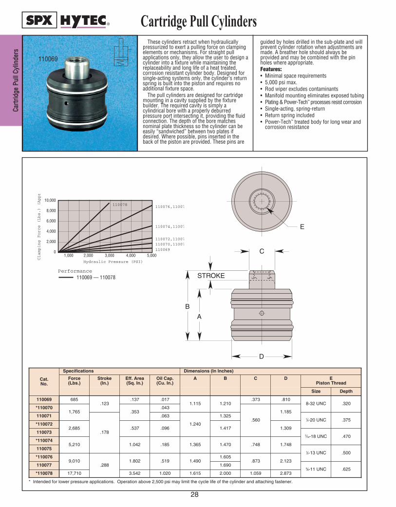
CCaarrtt
rriiddggee
PPuull
ll CCyyll
iinnddee
rrss
28
Cartridge Pull Cylinders
STROKE
B
A
E
C
D
Cat.No.
Specifications Dimensions (In Inches)
Force(Lbs.)
Stroke(In.)
Eff. Area(Sq. In.)
Oil Cap.(Cu. In.)
A B C D EPiston Thread
Size Depth
110069 685.123
.137 .0171.115 1.210
.373 .8108-32 UNC .320
*1100701,765 .353
.043
.560
1.185110071
.178
.063
1.240
1.3251⁄4-20 UNC .375
*1100722,685 .537 .096 1.417 1.309
1100735⁄16-18 UNC .470
*1100745,210 1.042 .185 1.365 1.470 .748 1.748
1100751⁄2-13 UNC .500
*1100769,010
.2881.802 .519 1.490
1.605.873 2.123
110077 1.6905⁄8-11 UNC .625
*110078 17,710 3.542 1.020 1.615 2.000 1.059 2.873
Clamping Force (Lbs.) (Approximate)
Performance 110069 — 110078
110078 110076,110077
110074,110075
110072,110073 110070,110071 110069
10,000
8,000
6,000
4,000
2,000
0 5,000 4,000 3,000 2,000 1,000
Hydraulic Pressure (PSI)
* Intended for lower pressure applications. Operation above 2,500 psi may limit the cycle life of the cylinder and attaching fastener.
110069
These cylinders retract when hydraulicallypressurized to exert a pulling force on clampingelements or mechanisms. For straight pullapplications only, they allow the user to design acylinder into a fixture while maintaining thereplaceability and long life of a heat treated,corrosion resistant cylinder body. Designed forsingle-acting systems only, the cylinder’s returnspring is built into the piston and requires noadditional fixture space.
The pull cylinders are designed for cartridgemounting in a cavity supplied by the fixturebuilder. The required cavity is simply acylindrical bore with a properly deburredpressure port intersecting it, providing the fluidconnection. The depth of the bore matchesnominal plate thickness so the cylinder can beeasily “sandwiched” between two plates ifdesired. Where possible, pins inserted in theback of the piston are provided. These pins are
guided by holes drilled in the sub-plate and willprevent cylinder rotation when adjustments aremade. A breather hole should always beprovided and may be combined with the pinholes where appropriate.Features:• Minimal space requirements• 5,000 psi max.• Rod wiper excludes contaminants• Manifold mounting eliminates exposed tubing• Plating & Power-Tech™ processes resist corrosion• Single-acting, spring-return• Return spring included• Power-Tech™ treated body for long wear and
corrosion resistance
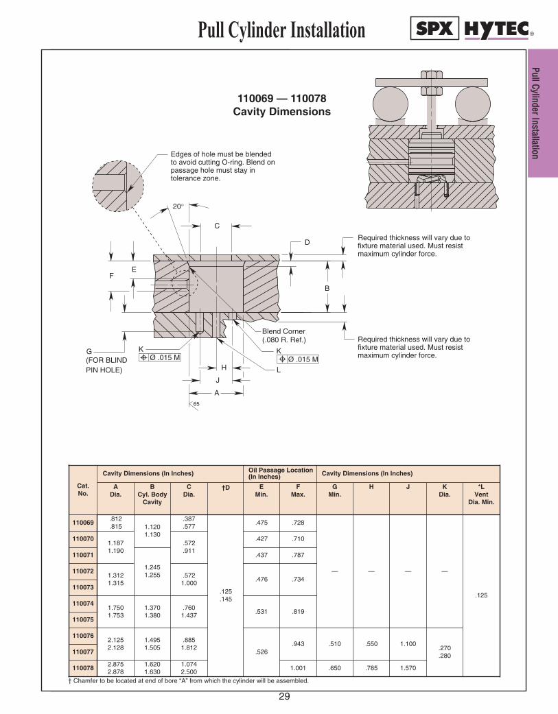
PPuullll CCyylliinnddeerr IInnssttaallllaattiioonn
29
Pull Cylinder Installation
110069 — 110078Cavity Dimensions
PIN HOLE)(FOR BLINDG
L
K K
Required thickness will vary due tofixture material used. Must resistmaximum cylinder force.
A
FE
C
B
20°
Edges of hole must be blendedto avoid cutting O-ring. Blend onpassage hole must stay intolerance zone.
(.080 R. Ref.)Blend Corner
D
J
H
Required thickness will vary due tofixture material used. Must resistmaximum cylinder force.Ø .015 M Ø .015 M
65
Cat.No.
Cavity Dimensions (In Inches)
KDia.
—
ADia.
BCyl. Body
Cavity
CDia.
110069.812.815 1.120
1.130
.387
.577
1100701.1871.190
.572
.911110071
1.2451.255
1100721.3121.315
.5721.000
110073
.270
.280
J
—
†D
.125
.145
Oil Passage Location(In Inches)
EMin.
.475
.427
.437
.476
1.100
1.570
FMax.
.728
.710
.787
.734
Cavity Dimensions (In Inches)
1100741.7501.753
1.3701.380
.7601.437
GMin.
—
.819110075
.510
.531
.650
1100762.1252.128
1.4951.505
.8851.812
.526.943
110077
H
—
.550
1100782.8752.878
1.6201.630
1.0742.500
.7851.001
*LVent
Dia. Min.
.125
† Chamfer to be located at end of bore “A” from which the cylinder will be assembled.
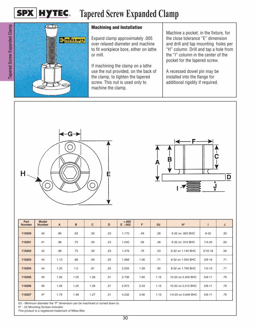
TTaappee
rreedd
SSccrree
ww EE
xxppaann
ddeedd
CCllaamm
pp
30
Machining and Installation
Expand clamp approximately .005over relaxed diameter and machineto fit workpiece bore, either on latheor mill.
If machining the clamp on a latheuse the nut provided, on the back ofthe clamp, to tighten the taperedscrew. This nut is used only tomachine the clamp.
Machine a pocket, in the fixture, forthe close tolerance “E” dimensionand drill and tap mounting holes per“H” column. Drill and tap a hole fromthe “I” column in the center of thepocket for the tapered screw.
A recessed dowel pin may beinstalled into the flange foradditional rigidity if required.
PartNumber
110200
110201
110202
110203
110204
110205
110206
110207
G† - Minimum diameter the “F” dimension can be machined or turned down to.H* - (3) Mounting Screws Included.This product is a registered trademark of Mitee-Bite.
ModelNumber
#0
#1
#2
#3
#4
#5
#6
#7
A
.86
.98
.98
1.13
1.25
1.56
1.56
1.79
B
.63
.75
.75
.88
1.0
1.25
1.25
1.48
C
.59
.59
.59
.69
.81
1.06
1.06
1.27
D
.23
.23
.23
.25
.25
.31
.31
.31
+.000E -.002
1.170
1.240
1.476
1.968
2.205
2.736
2.972
4.232
F
.49
.56
.79
1.06
1.39
1.65
2.03
3.06
G†
.28
.48
.53
.71
.90
1.15
1.15
1.15
H*
6-32 on .825 BHC
6-32 on .910 BHC
6-32 on 1.140 BHC
8-32 on 1.550 BHC
8-32 on 1.790 BHC
10-32 on 2.200 BHC
10-32 on 2.515 BHC
1/4-20 on 3.646 BHC
I
8-32
1/4-20
5/16-18
3/8-16
1/2-13
5/8-11
5/8-11
5/8-11
J
.30
.50
.56
.71
.71
.79
.79
.79
Tapered Screw Expanded Clamp

UUnniiffoorrccee
® ®HH
yyddrraauulliicc CCllaammppss
31
Uniforce® HydraulicClamp for a variety of fixturing applications
A
B
C
D
E
F
TThhee UUnniiffoorrccee HHyyddrraauulliicc CCllaammpp ccaann bbeetthhee ffoouunnddaattiioonn ffoorr ccllaammppiinngg aa wwiiddeevvaarriieettyy ooff wwoorrkkppiieecceess::
AA..For more than just rectangularworkpieces, the Uniforce hydraulic clamp can be equally effective for clampinground workpieces.
BB..Often, a single Uniforce hydraulic clampis all that is necessary to securely hold aworkpiece. Or, several clamps can bepositioned along the length of the part.
CC..The hydraulic actuation of this clamprequires no additional space. Fixture density is not compromised because thehydraulic pull cylinder is buried belowthe workpieces. The Uniforce clampingelements can be purchased as bar stockand then customized to meet speciallength requirements.
DD.. Applications can include castings as wellas bar-stock and extrusions. The clampwill accommodate slight imperfectionsand draft angles.
EE.. Five clamp sizes, each available in twodifferent pressure ratings are available to fit a wide range of workpiece proportions.
FF.. The Uniforce Hydraulic Clamp can clamptwo workpieces as easily as one. Thesame clamping force is exerted onworkpiece whether clamping one or two.

CCllaamm
ppss
32
CLAMPSRReettrraacctt CCllaammppss
Very similar in operation to the swingclamps, with the exception of having theclamping arm move out toward theworkpiece in a straight line rather thanrotating 90°, making them ideal forapplications where the shape of the fixture orpart does not allow room for the clamp toswing.
An internal sequence valve controls andcoordinates the retracting and clampingactions. When hydraulic pressure is appliedto the advance port, a piston causes theclamping arm to extend into the clampedposition. As pressure increases above 450psi the sequence valve opens, causing theclamping piston to extend, which in turn
causes the clamping arm to pivot andclamp the workpiece.
When pressure is released, thesingle-acting clamping cylinder'sreturn spring retracts the clampingcylinder. At the same time, a returnspring moves the clamping arm backto its un-clamped position. Theretract mechanism is single- ordouble-acting and can be assistedwith hydraulic or shop air pressure toreturn the clamping arm.
EEddggee CCllaammppHytec’s edge clamp performs three
functions: locating the workpiece,clamping horizontally againstsecondary locators and clampingvertically against the primary locatingsurface. This combined horizontaland vertical clamping force canlocate and secure many parts with noother clamps being needed.
DDiiee CCllaammppOriginally designed for die
clamping, this clamp's unique mountingarrangement allows it to be used in a varietyof workholding applications too. Just use ariser block the same thickness as theworkpiece.
Rotation is specified by looking "down" atthe piston rod end of the clamp. Clockwiserotation is designated as right hand rotationand counter-clockwise, left hand.
SSwwiinngg CCllaammppssTwo separate actuators are used to
perform the clamping function. First, acylinder is used to swing the clamping arm90° into position over the workpiece. Then asecond cylinder is sequenced to pivot theclamping arm into contact with theworkpiece and hold it in place.
An internal sequence valve controls andcoordinates both the swinging and clampingactions. When hydraulic pressure is appliedto the advance port, a piston causes the
clamping arm to swing into the clampedposition. As pressure goes above 450 psi, thesequence valve opens, causing the clampingpiston to extend, which causes the clampingarm to pivot and clamp the workpiece.
When pressure is released, the single-acting clamping cylinder's return springretracts the clamping cylinder. At the sametime, a return spring in the swing mechanismmoves the clamping arm back to itsunclamped position. The swing mechanismis single- or double-acting, and can beassisted with hydraulic or shop air pressureto return the clamping arm.
Hytec’s workholding devices includemany types of hydraulic clamps thatwill handle most clampingapplications. All of our hydraulicclamps are ideal for applicationswhere it is necessary for theclamping actuator to be moved awayfrom the workpiece. They performthe same function as clampingcylinders, but their ability to swing orretract out of the way of cutters, plusthe advantage of quick and easy partloading or unloading, makes themthe perfect choice for the jobs withspecial workholding needs.
SSwwiinngg//PPuullll CCllaammppssBoth the swinging and clamping
functions are performed by a singleactuator: as the clamp’s cylinder isretracted, the rod rotates, causingthe clamping arm to swing intoposition. Clamping then takes placeas the cylinder continues to retract,pulling the arm against theworkpiece.
Hytec features a family of “liveroller” swing clamps. With thisdesign, the swing mechanism uses awide roller that follows a camthroughout the clamp’s stroke toprovide the rotation. The heat-treated roller and cam provideincreased service life in the toughestapplications. Swings of 0° (straightpull) and 90° (both right and lefthand) are available. 30°, 45° and60° rotations are available in somesizes.
Hytec offers a wide range ofmounting and plumbing options.Body styles include: threaded body, cartridgeand manifold mount. With the threaded body,double-acting options, choose from top andbottom ports or both ports at the top in the2,400 lb. capacity clamps.
Single-acting and double-acting versionsare available. In double-acting, there is achoice of clamping stroke lengths in somesizes.
Arms clamp securely to the piston rod tominimize deflection. Choose from a standardlength arm or an easily modified long arm tobest fit your application.

33
LLiivvee--RRoolllleerr SSww
iinngg CCllaammpp
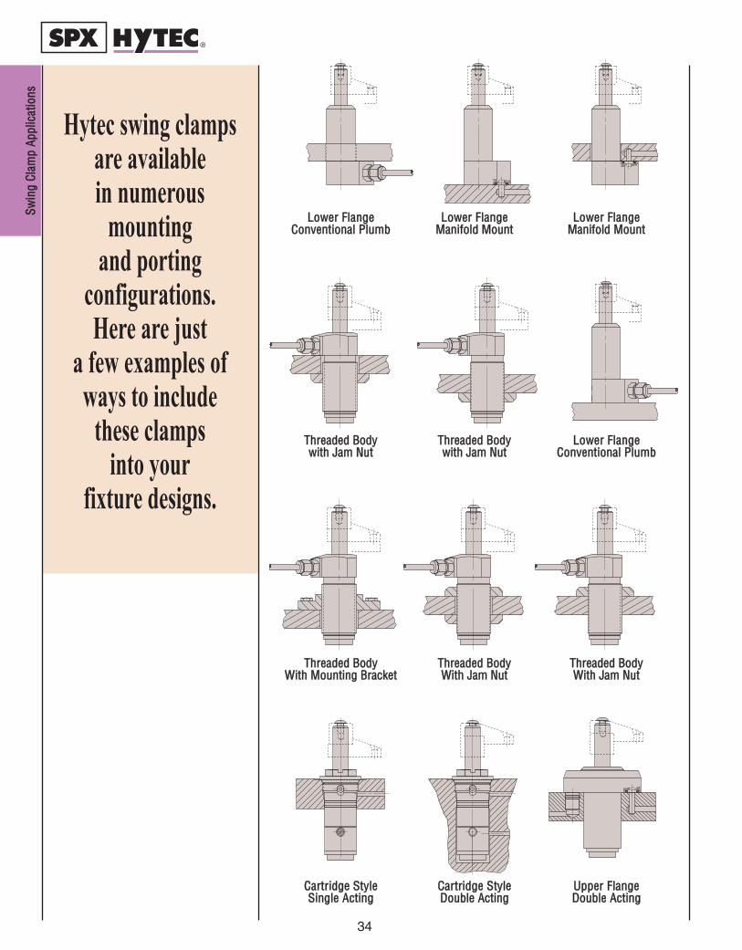
SSwwiinn
gg CCll
aammpp
AAppppll
iiccaatt
iioonnss
34
Hytec swing clampsare available in numerous
mounting and porting
configurations. Here are just
a few examples ofways to include
these clamps into your
fixture designs.
LLoowweerr FFllaannggeeCCoonnvveennttiioonnaall PPlluummbb
LLoowweerr FFllaannggeeMMaanniiffoolldd MMoouunntt
LLoowweerr FFllaannggeeMMaanniiffoolldd MMoouunntt
TThhrreeaaddeedd BBooddyy wwiitthh JJaamm NNuutt
LLoowweerr FFllaannggeeCCoonnvveennttiioonnaall PPlluummbb
TThhrreeaaddeedd BBooddyy wwiitthh JJaamm NNuutt
TThhrreeaaddeedd BBooddyyWWiitthh MMoouunnttiinngg BBrraacckkeett
TThhrreeaaddeedd BBooddyy WWiitthh JJaamm NNuutt
TThhrreeaaddeedd BBooddyy WWiitthh JJaamm NNuutt
CCaarrttrriiddggee SSttyylleeSSiinnggllee AAccttiinngg
UUppppeerr FFllaannggee DDoouubbllee AAccttiinngg
CCaarrttrriiddggee SSttyylleeDDoouubbllee AAccttiinngg
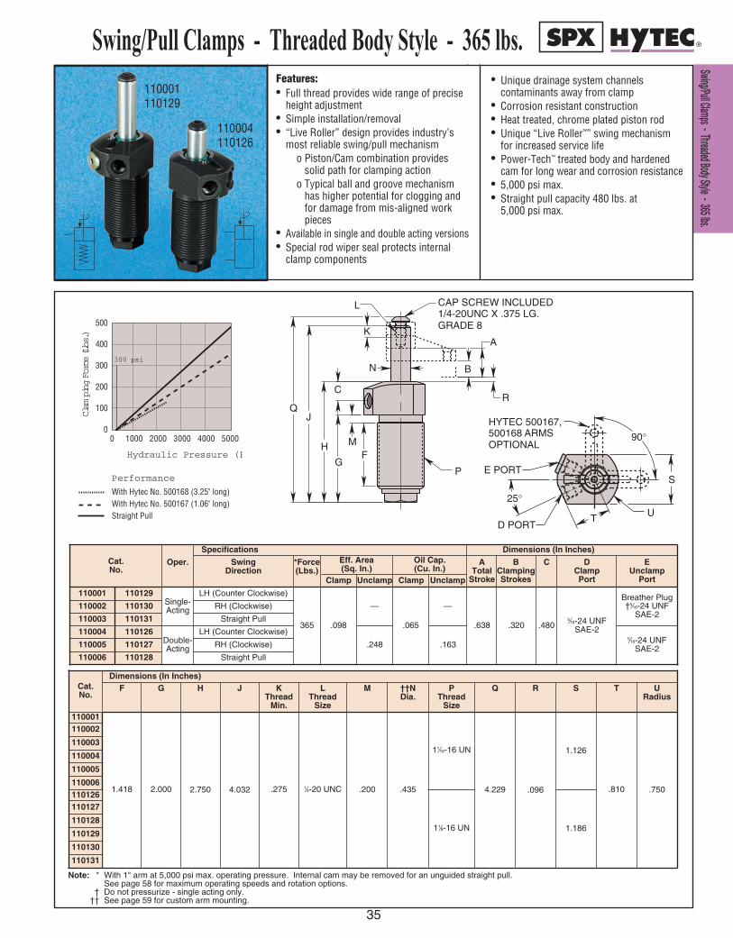
SS ww ii nn gg // PP uu ll ll CC ll aa mm pp ss -- TT hh rr ee aa dd ee dd BB oo dd yy SS tt yy ll ee -- 33 66 55 ll bb ss ..
35
Features:• Full thread provides wide range of precise
height adjustment • Simple installation/removal• “Live Roller” design provides industry’s
most reliable swing/pull mechanismo Piston/Cam combination provides
solid path for clamping actiono Typical ball and groove mechanism
has higher potential for clogging and for damage from mis-aligned work pieces
• Available in single and double acting versions• Special rod wiper seal protects internal
clamp components
• Unique drainage system channelscontaminants away from clamp
• Corrosion resistant construction• Heat treated, chrome plated piston rod• Unique “Live Roller™” swing mechanism
for increased service life• Power-Tech™ treated body and hardened
cam for long wear and corrosion resistance• 5,000 psi max.• Straight pull capacity 480 lbs. at
5,000 psi max.
110001110129
110004110126
Swing/Pull Clamps - Threaded Body Style - 365 lbs.
300 psi
Clam
ping Force (Lbs.)
0 1000 2000 3000 4000 5000
500
400
300
200
100
0
Hydraulic Pressure (PSI)
Performance
With Hytec No. 500168 (3.25" long)With Hytec No. 500167 (1.06" long)Straight Pull
A
Q
K
J
P
OPTIONAL500168 ARMSHYTEC 500167,
S
UTD PORT
25°
E PORT
90°
R
B
GRADE 81/4-20UNC X .375 LG.CAP SCREW INCLUDEDL
N
H
C
G
MF
A
Q
K
J
P
OPTIONAL500168 ARMSHYTEC 500167,
S
UTD PORT
25°
E PORT
90°
R
B
GRADE 81/4-20UNC X .375 LG.CAP SCREW INCLUDEDL
N
H
C
G
MF
Cat.No.
Specifications Dimensions (In Inches)
Oper. Swing Direction
*Force(Lbs.)
Eff. Area(Sq. In.)
Oil Cap.(Cu. In.)
ATotal
Stroke
BClampingStrokes
C DClampPort
EUnclamp
PortClamp Unclamp Clamp Unclamp
Single-Acting
LH (Counter Clockwise)
365 .098
—
.065
—
.638 .320 .4805⁄16-24 UNF
SAE-2
Breather Plug†5⁄16-24 UNF
SAE-2RH (Clockwise)
110003 110131 Straight Pull
110004 110126Double-Acting
LH (Counter Clockwise)
.248 .1635⁄16-24 UNF
SAE-2110005 110127 RH (Clockwise)
110006 110128 Straight Pull
Cat.No.
Dimensions (In Inches)F G H J K
ThreadMin.
LThread
Size
M ††NDia.
P Thread
Size
Q R S
110001
1.418 2.000 2.750 4.032 .275 1⁄4-20 UNC .200 .435
11⁄16-16 UN
11⁄8-16 UN
4.229 .096
1.186
1.126
110002
110003
110004
110005
110006.810
T
.750
URadius
110126110127
110128
110129
110130
110131
Note: * With 1" arm at 5,000 psi max. operating pressure. Internal cam may be removed for an unguided straight pull. See page 58 for maximum operating speeds and rotation options.
† Do not pressurize - single acting only.†† See page 59 for custom arm mounting.
110002 110130
110001 110129
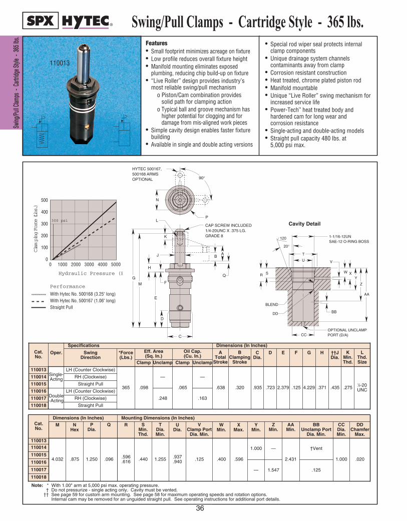
WWoorr
kkhhooll
ddiinngg
DDeevv
iicceess
SSwwiinngg
//PPuullll CC
llaammppss
-- CC
aarrttrriidd
ggee SStt
yyllee --
336655
llbbss..
36
Features• Small footprint minimizes acreage on fixture• Low profile reduces overall fixture height• Manifold mounting eliminates exposed
plumbing, reducing chip build-up on fixture• “Live Roller” design provides industry’s
most reliable swing/pull mechanismo Piston/Cam combination provides
solid path for clamping actiono Typical ball and groove mechanism has
higher potential for clogging and fordamage from mis-aligned work pieces
• Simple cavity design enables faster fixturebuilding
• Available in single and double acting versions
• Special rod wiper seal protects internalclamp components
• Unique drainage system channelscontaminants away from clamp
• Corrosion resistant construction• Heat treated, chrome plated piston rod• Manifold mountable• Unique “Live Roller” swing mechanism for
increased service life• Power-Tech™ heat treated body and
hardened cam for long wear and corrosion resistance
• Single-acting and double-acting models• Straight pull capacity 480 lbs. at
5,000 psi max.
Swing/Pull Clamps - Cartridge Style - 365 lbs.
300 psi
Clam
ping Force (Lbs.)
0 1000 2000 3000 4000 5000
500
400
300
200
100
0
Hydraulic Pressure (PSI)
Performance
With Hytec No. 500168 (3.25" long)With Hytec No. 500167 (1.06" long)Straight Pull
J
N
B
K
E
D
F
H
G
M
A
C
OPTIONAL500168 ARMSHYTEC 500167,
GRADE 81/4-20UNC X .375 LG.CAP SCREW INCLUDED
P
90°
Q
L
CAVITY DETAIL
SAE-12 O-RING BOSS1-1/16-12UN
T
R S
CC
BLEND
DD
W XY
Z
AA
BB
V
20°
120
U
PORT (D/A)OPTIONAL UNCLAMP
110013
Cavity Detail
Cat.No.
Specifications Dimensions (In Inches)
Oper. Swing Direction
*Force(Lbs.)
Eff. Area(Sq. In.)
Oil Cap.(Cu. In.)
ATotal
Stroke
BClamping
Stroke
CDia.
Clamp Unclamp Clamp Unclamp
110013Single-Acting
LH (Counter Clockwise)
365 .098
—
.065
—
.638 .320 .935
110014 RH (Clockwise)
110015 Straight Pull
110016Double-Acting
LH (Counter Clockwise)
.248 .163110017 RH (Clockwise)
110018 Straight Pull
Cat.No.
M NHex
PDia.
Q R SMin.Thd.
TDia.Min.
UDia.
VClamp Port
Dia. Min.
WMin.
110013
4.032 .875 1.250 .096 .596.616 .440 1.255 .937
.940 .125 .400
110014
110015
110016
110017
110018
.596
XMax.
1.000
YMin.
Dimensions (In Inches)
—
ZMin.
2.431
AAMin.
†Vent
BBUnclamp Port
Dia. Min.
1.000
CCDia.Min.
.020
DDChamfer
Max.
D
.723
E
2.379
F
.125
G
4.229
H
.371
††JDia.
.435
KMin.Thd.
.275
LThd.Size
1⁄4-20UNC
— 1.547 .125
Mounting Dimensions (In Inches)
Note: * With 1.00" arm at 5,000 psi max. operating pressure. † Do not pressurize - single acting only. Cavity must be vented.
†† See page 59 for custom arm mounting. See page 58 for maximum operating speeds and rotation options.Internal cam may be removed for an unguided straight pull. See operating instructions for additional port details.

S Sw wi in ng g/ /P Pu ul ll l C Cl la am mp p - - M Ma an ni if fo ol ld d M Mo ou un nt t – – U Up pp pe er r F Fl la an ng ge e S St ty yl le e - - 3 36 65 5 l lb bs s. .
37
Features• Unique connector bushing provides positive
mating with fixture, reducing the potential forleakage or weeping.
• Simple cavity design eliminates need forthreaded holes in mating surfaces
• Manifold design eliminates external plumbingand reduces fixture height
• “Live Roller” design provides industry’s mostreliable swing/pull mechanism
o Piston/Cam combination provides solidpath for clamping action
o Typical ball and groove mechanism has higher potential for clogging and for damage from mis-aligned work pieces
• Available in single and double acting versions
• Special rod wiper seal protects internal clampcomponents
• Unique drainage system channelscontaminants away from clamp
• Corrosion resistant construction• Heat treated, chrome plated piston rod • Manifold mountable• Unique “Live Roller” swing mechanism for
increased service life• Power-Tech™ heat treated body and hardened
cam for long wear and corrosion resistance• Single- and double-acting models are
dimensionally interchangeable• Straight pull capacity 480 lbs. at
5,000 psi max.
Swing/Pull Clamp - Manifold Mount – Upper Flange Style - 365lbs.
110007
W
EJ
F
G
K
M BA
H
OPTIONAL500168 ARMSHYTEC 500167,
90°
D
C
GRADE 81/4-20UNC X .375 LG.CAP SCREW INCLUDEDL
RQ
S BB
PN
.015 RADIUSMAX
125125
20° X
.070
.050Y
AA
V
U
SEE PORTDETAIL
T
Ø .015 M A S B M Ø .015 M A S B M
-A-
Ø .015 M A S-B-
300 psi
Clam
ping Force (Lbs.)
0 1000 2000 3000 4000 5000
500
400
300
200
100
0
Hydraulic Pressure (PSI)
Performance
With Hytec No. 500168 (3.25" long)With Hytec No. 500167 (1.06" long)Straight Pull
Cat.No.
Dimensions (In Inches)
.995
MDia.
NMtng.
PMtng.
QMtng.
RMtng.
SMtng.
TThd.Size
UDia.
V W
.481
AADia.Max.
—
BBMtng.
110007
††.435 .632 .316 1.510 .755 .995 10-24UNC
1.0001.030
— †Vent110008
110009
110010
110011
110012
.500
.503
XDia.
.640
.660
Y
Cat.No.
Specifications
D
1.090
Dimensions (In Inches)
E
.096
F
1.815
Oper. Swing Direction
*Force(Lbs.)
Eff. Area(Sq. In.)
Oil Cap.(Cu. In.)
GATotal
Stroke
BClamping
Stroke
CDia.
2.217
H
.805
J
Clamp Unclamp Clamp Unclamp
4.229
KMin.Thd.
.275
110007Single-Acting
LH (Counter Clockwise)
365 .098
—
.065
—
.638 .320 2.624
LThd.Size
1⁄4-20UNC
110008 RH (Clockwise)
110009 Straight Pull
110010Double-Acting
LH (Counter Clockwise)
.248 .163110011 RH (Clockwise)
110012 Straight Pull
†††.250 —
Note: * With 1.00" arm at 5,000 psi max. operating pressure. † Do not pressurize - single acting only.
†† See page 59 for custom arm mounting.Internal cam may be removed for an unguided straight pull.
See page 58 for maximum operating speeds and rotation options.††† Surface finish to be 63. Finish of 125 acceptable with concentric tool
marks only. Finish area to be .500 DIA. min. centered on .250 DIA. port hole.See operating instructions for additional port details.

SSwwiinngg//
PPuullll CCll
aammpp --
MMaanniiffoolldd
MMoouunntt
–– LLoowwee
rr FFllaanngg
ee SSttyyllee
-- 336655 ll
bbss..
38
Features• Manifold design eliminates external
plumbing and reduces fixture height• “Live Roller” design provides industry’s
most reliable swing/pull mechanismo Piston/Cam combination provides
solid path for clamping actiono Typical ball and groove mechanism
has higher potential for clogging and for damage from mis-aligned work pieces
• Available in single and double actingversions
• Special rod wiper seal protects internalclamp components
• Unique drainage system channels
contaminants away from clamp• Corrosion resistant construction• Heat treated, chrome plated piston rod• Manifold mountable• Unique “Live Roller” swing mechanism for
increased service life• Power-Tech® treated body and hardened cam
for long wear and corrosion resistance• Single-acting and double-acting models are
dimensionally interchangeable• Straight pull capacity 480 lbs. at 5,000 psi max.• Flange top or bottom mounting
Swing/Pull Clamp - Manifold Mount – Lower Flange Style - 365 lbs.
110144
Cat.No.
Dimensions (In Inches)J K L M N
ThreadMin.
PThread
Size
R S T U V
110144
1.800 2.780 4.045 4.302 .275 1⁄4-20 UNC 1.250 1.870 1.770 .412 .684 1.185
110145110146110147110148110149
1.110
W
.824
X
10-24 UNC
Cat.No.
Specifications Dimensions (In Inches)Oper. Swing
Direction*Force(Lbs.)
Eff. Area (Sq. In.) Oil Cap. (Cu. In.) ATotal
Stroke
BClamping
Stroke
C †††DPortDia.
EClampPortClamp Unclamp Clamp Unclamp
110144Single-Acting
LH (Counterclockwise)
365 .098
—
.065
—
.638 .320 .096 .309Max.
5⁄16-24UNF
SAE-2
110145 RH (Clockwise)
110146 Straight Pull
110147Double-Acting
LH (Counterclockwise)
.248 .163110148 RH (Clockwise)
110149 Straight Pull
BreatherPlug
†5⁄16-24 UNFSAE-2
FUnclamp
Port
.435
††GDia.
1.070
HDia.
300 psi
Clam
ping Force (Lbs.)
0 1000 2000 3000 4000 5000
500
400
300
200
100
0
Hydraulic Pressure (PSI)
Performance
With Hytec No. 500168 (3.25" long)With Hytec No. 500167 (1.06" long)Straight Pull
C
H
G
J
K
LM
P
BA
N
CAP SCREW INCLUDED1/4-20 UNC X .375 LGGRADE 8
Y
Y
DD
XT
WV
UU
V
UU
BOTTOMTOP
DD
AA
Z
BBCC
(2 PLACES)O-RING
(2 PLACES)O-RING
Top View Bottom View Mounting Options
Mating Hole Pattern
5⁄16-24 UNFSAE-2
NOTE: * With 1.00” long arm at 5,000 psi maximum operating pressure. † Do not pressurize - single-acting only.†† See page 59 of H05 for custom arm mounting. Internal cam may be
removed for an unguided straight pull. See page 58 of H05 for maximum operating speeds.
††† Surface finish to be 63. Finish of 125 acceptable with concentric toolmarks only. Finish area to be .525 DIA. min. centered on .309 DIA. porthole. See operating instructions for additional port details.
HYTEC500154,500155Arms(Optional)
F PORT
Q
E PORT
R
S
90°
AADia.
.395 1.0951.125 .445
BB
.890
YThread
Size
CCZ
.770
DDQRadius
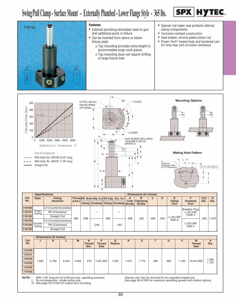
Swing/Pull Clamp - Surface Mount – Externally Plumbed - Lower Flange Style - 365 lbs.
39
Features• External plumbing eliminates need to gun
drill additional ports in fixture• Can be inserted from above or below
fixture plateo Top mounting provides extra height to
accommodate large work pieceso Top mounting does not require drilling
of large fixture hole
• Special rod wiper seal protects internalclamp components
• Corrosion reisitant construction• Heat treated, chrome plated piston rod• Power-Tech® treated body and hardened cam
for long wear and corrosion resistance
110150
30°
30°
F PORT
Q E PORTR
90°
H
G
CJ
K
LM
HYTEC 500167,500168 ARMSOPTIONAL
D
P
B AN
S
CAP SCREW INCLUDED1/4-20 UNC X .375 LGGRADE 8
300 psi
Clam
ping Force (Lbs.)
0 1000 2000 3000 4000 5000
500
400
300
200
100
0
Hydraulic Pressure (PSI)
Performance
With Hytec No. 500168 (3.25" long)With Hytec No. 500167 (1.06" long)Straight Pull
V
T
X (Optional Clearance Hole for “H” Dimension
W
U
U
M .015 A L
Mating Hole Pattern
Mounting Options
Cat.No.
Specifications Dimensions (In Inches)Oper. Swing
Direction*Force(Lbs.)
Eff. Area (Sq. In.) Oil Cap. (Cu. In.) ATotal
Stroke
BClamping
Stroke
C D EClampPortClamp Unclamp Clamp Unclamp
110150Single-Acting
LH (Counterclockwise)
365 .098
—
.065
—
.638 .320 .096 .5407⁄16-20 UNF
SAE-4
110151 RH (Clockwise)
110152 Straight Pull
110153Double-Acting
LH (Counterclockwise)
.248 .163110154 RH (Clockwise)
110155 Straight Pull
7⁄16-20 UNFSAE-4
Breather Plug7⁄16-20 UNF
†SAE-4
FUnclamp
Port
.435
††GDia.
1.070
HDia.
Cat.No.
Dimensions (In Inches)J K L M N
ThreadMin.
PThread
Size
QRadius
R S T U V
110150
1.800 2.780 4.045 4.302 .275 1⁄4-20 UNC 1.250 1.870 1.770 .395 .684 1.185
110151
110152
110153
110154
110155
10-24 UNC
WThread
Size
1.0951.125
XDia.
NOTE: * With 1.00" long arm at 5,000 psi max. operating pressure. † Do not pressurize - single-acting only. †† See page 59 of H05 for custom arm mounting.
Internal cam may be removed for an unguided straight pull.See page 58 of H05 for maximum operating speeds and rotation options.
Swing/Pull Clamp - Surface Mount – Externally Plumbed - Lower Flange Style - 365 lbs.

SS wwii nn gg
// PP uull ll CC
ll aa mmpp ss
-- TT hh
rr ee aadd ee dd
BB oodd yy
SS tt yyll ee
-- 7755 00
ll bb ss..
40
100945 100948
Cat. No.
Dimensions (In Inches)
100945100946100947100948100949100950
.823.9951.428.1085.13911⁄4–12UNF.560.2831⁄4 –20UNC.2754.9123.3272.497
URadius
TSRQPThread
Size
††NDia.
MLThread
Size
KThread
Min.
JHG
Cat. No.
Specifications Dimensions (In Inches)
Oper. Swing Direction *Force(Lbs.)
Eff. Area(Sq. In.)
Oil Cap.(Cu. In.)
ATotal
Stroke
BClamping
Stroke
C DClampPort
EUnclamp
Port
F
Clamp Unclamp Clamp Unclamp100945
Single-Acting
Left Hand (Counter Clockwise)
750 .195
–
.160
–
.818 .345 .4927⁄16 –20UNF
SAE-4
Breather Plug 7⁄16 –20UNF
SAE-4†1.770
100946 Right Hand (Clockwise)100947 Straight Pull
Double-Acting
Left Hand (Counter Clockwise).441 .360
7⁄16 –20UNFSAE-4100949 Right Hand (Clockwise)
100950 Straight Pull
100948
NOTE: * With 1.25" long arm at 5,000 psi maximum operating pressure.† Do not pressurize – single-acting only.†† See page 59 for custom arm mounting.
Internal cam may be removed for an unguided straight pull.See page 58 for maximum operating speeds.
100945-48
T
U
90° HYTEC 500154,500155 ARMS(OPTIONAL)
S
E PORT
23°
BA
R
CAP SCREW INCLUDED1/4–20UNC X .375 LGGRADE 8K
L
N
C
M
FG
H
J
Q
P
D PORT
Top View
Swing/Pull Clamps - Threaded Body Style - 750 lbs.Features:• Full thread provides wide range of precise
height adjustment • Simple installation/removal• “Live Roller” design provides industry’s most
reliable swing/pull mechanismo Piston/Cam combination provides
solid path for clamping actiono Typical ball and groove mechanism
has higher potential for clogging and for damage from mis-aligned work pieces
• Available in single and double acting versions• Special rod wiper seal protects internal clamp
components
• Unique drainage system channelscontaminants away from clamp
• Corrosion resistant construction• Heat treated, chrome plated piston rod• Unique “Live Roller™” swing mechanism for
increased service life• Power-Tech™ treated body and hardened cam
for long wear and corrosion resistance• Single and double acting models are
dimensionally interchangeable• Straight pull cap. 950 lbs. at 5,000 psi max
(without arms).

Swing/Pull Clamps - Cartridge Style - 750 lbs.
41
Features:• Small footprint minimizes acreage on fixture• Low profile reduces overall fixture height• Manifold mounting eliminates exposed
plumbing, reducing chip build-up on fixture• “Live Roller” design provides industry’s
most reliable swing/pull mechanismo Piston/Cam combination provides
solid path for clamping actiono Typical ball and groove mechanism has
higher potential for clogging and fordamage from mis-aligned work pieces
• Simple cavity design enables faster fixturebuilding
• Available in single and double acting versions
• Special rod wiper seal protects internalclamp components
• Unique drainage system channelscontaminants away from clamp
• Corrosion resistant construction• Heat treated, chrome plated piston rod• Manifold mountable• Unique “Live Roller” swing mechanism for
increased service life• Power-Tech™ treated body and hardened
cam for long wear and corrosion resistance• Single and double-acting models are
dimensionally interchangeable.• Straight pull capacity 950 lbs. at 5,000 psi
maximum
100951100952
Swing/Pull Clamps - Cartridge Style - 750 lbs.
Note: * With 1.25" long arm at 5,000 psi max. operating pressure.† Do not pressurize - single-acting only. Cavity must be vented.†† See page 59 for custom arm mounting.
Internal cam may be removed for an unguided straight pull. See operating instructions for additional port details.See page 58 for maximum operating speeds.
100951
Cat.No.
Dimensions (In Inches)
KMin.
Thread
LThread
Size
M NHex.
PDia.
Q R SMin.
Thread
TDia.Min.
UDia.
VClampPort
Dia. Min.
WMin.
XMax.
YMin.
ZMin.
AAMin.
BBUnclamp
PortDia. Min.
CCDia.Min.
DDChamfer
Max.
.275 1⁄4–20UNC 4.912 1.000 1.500 .108.665.695
.430 1.5601.1871.190
.125 .430 .604
1.063 –
3.044
†Vent
1.187 .020100953100957
– 1.912 .125100958
100959
Cat. No.
Oper.Specifications Dimensions (In Inches)
Swing Direction
*Force(Lbs.)
Eff. Area(Sq. In.)
Oil Cap.(Cu. In.)
ATotal
Stroke
BClamping
Stroke
CDia.
D E F G H ††JDia.
100951
Single-Acting
750 .195
–
.160
–
.818 .345 1.185 1.245 2.956 .125 5.139 .371 .560
100952 Right Hand(Clockwise)
100953 Straight Pull
100957
Double-Acting
Left Hand(Counter Clockwise)
.441 .360100958 Right Hand(Clockwise)
100959 Straight Pull
ClampClamp Unclamp UnclampLeft Hand
(Counter Clockwise)
AA
ZY
XW
V
BB
OPTIONAL UNCLAMPPORT (D/A)
SR
CC
BLEND
DD
1 5/16 –12UNSAE–16 O-RING BOSS
UT
20° 120
CAP SCREW INCLUDED1/4– 20UNF X .375 LGGRADE 8
K
D
E
F
H
L
G
C
J BA
Q
N
P
90° HYTEC 500154, 500155ARMS (OPTIONAL)
M
300 PSI
0
1000
800
600
400
200
0
Clam
ping Force (Lbs.)
Performance
Clamp Nos.100945, 100946, 100947,100948, 100949, 100950
With Hytec 500155 Arm (4.25" long)With Hytec 500154 Arm (1.25" long)Straight Pull Force Without Arms
Hydraulic Pressure (PSI)1000 2000 3000 4000 5000
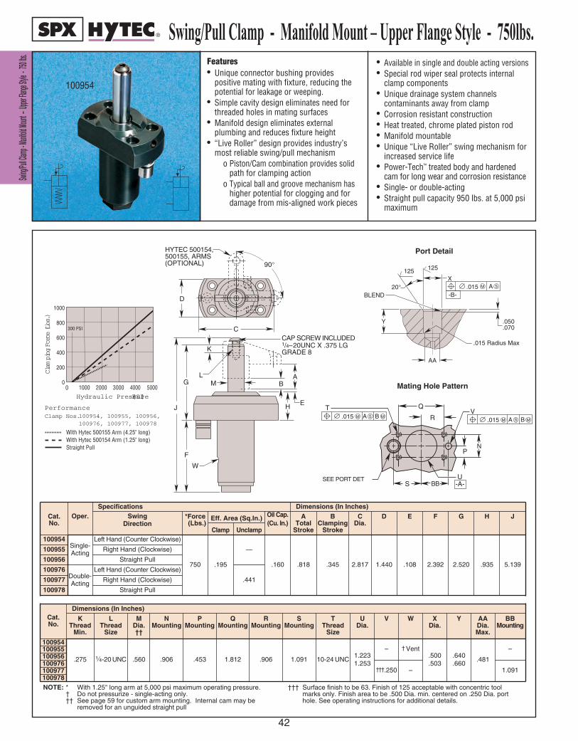
SSwwiinngg//
PPuullll CCll
aammpp -- MM
aanniiffoolldd
MMoouunntt
–– UUpp
ppeerr FFllaa
nnggee SSttyy
llee -- 7755
00 llbbss..
42
Features• Unique connector bushing provides
positive mating with fixture, reducing thepotential for leakage or weeping.
• Simple cavity design eliminates need forthreaded holes in mating surfaces
• Manifold design eliminates externalplumbing and reduces fixture height
• “Live Roller” design provides industry’smost reliable swing/pull mechanism
o Piston/Cam combination provides solidpath for clamping action
o Typical ball and groove mechanism has higher potential for clogging and for damage from mis-aligned work pieces
• Available in single and double acting versions• Special rod wiper seal protects internal
clamp components• Unique drainage system channels
contaminants away from clamp• Corrosion resistant construction• Heat treated, chrome plated piston rod• Manifold mountable• Unique “Live Roller” swing mechanism for
increased service life• Power-Tech™ treated body and hardened
cam for long wear and corrosion resistance• Single- or double-acting• Straight pull capacity 950 lbs. at 5,000 psi
maximum
Swing/Pull Clamp - Manifold Mount – Upper Flange Style - 750lbs.
100954
Port Detail
Mating Hole Pattern
100954
D
C
HYTEC 500154,500155, ARMS(OPTIONAL) 90°
CAP SCREW INCLUDED1/4– 20UNC X .375 LGGRADE 8K
LMG
F
W
JE
AB
H
M S.015-B-
A
Y
125 125
X20°
BLEND
.050
.070
.015 Radius Max
AA
SUSEE PORT DET
AIL
T
-A-
M.015 A B MSM.015 A B MS
PN
Q
RV
BB
300 PSI
0
1000
800
600
400
200
0
Clam
ping Force (Lbs.)
PerformanceClamp Nos.100954, 100955, 100956, 100976, 100977, 100978
With Hytec 500155 Arm (4.25" long)With Hytec 500154 Arm (1.25" long)Straight Pull
Hydraulic Pressure (PSI)1000 2000 3000 4000 5000
NOTE: * With 1.25" long arm at 5,000 psi maximum operating pressure.† Do not pressurize - single-acting only.†† See page 59 for custom arm mounting. Internal cam may be
removed for an unguided straight pull
††† Surface finish to be 63. Finish of 125 acceptable with concentric toolmarks only. Finish area to be .500 Dia. min. centered on .250 Dia. porthole. See operating instructions for additional details.
Cat. No.
Dimensions (In Inches)
K Thread
Min.
L Thread
Size
M Dia. ††
NMounting
PMounting
QMounting
RMounting
SMounting
T Thread
Size
UDia.
V W XDia.
Y AADia. Max.
BBMounting
100954
.275 1⁄4-20 UNC .560 .906 .453 1.812 .906 1.091 10-24 UNC1.2231.253
– † Vent.500.503
.640
.660.481
–100955100956100976
†††.250 – 1.091100977100978
Cat. No.
SpecificationsOper.
Single-Acting
.160
Dimensions (In Inches)
—
Double-Acting
100976 Left Hand (Counter Clockwise).195
Oil Cap.(Cu. In.)
Eff. Area (Sq.In.)Swing Direction
*Force(Lbs.)
ATotal
Stroke
BClamping
Stroke
CDia.
D E F G H J
100954 Left Hand (Counter Clockwise)
750 .818 .345 2.817 1.440 .108 2.392 2.520 .935 5.139
100955 Right Hand (Clockwise)
100956 Straight Pull
100977 Right Hand (Clockwise)
100978 Straight Pull
UnclampClamp
.441
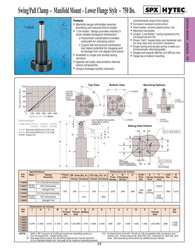
S Sw wi in ng g/ /P Pu ul ll l C Cl la am mp p - - M Ma an ni if fo ol ld d M Mo ou un nt t – – L Lo ow we er r F Fl la an ng ge e S St ty yl le e - - 7 75 50 0 l lb bs s. .
43
NOTE: * With 1.25” long arm at 5,000 psi maximum operating pressure. † Do not pressurize - single-acting only.†† See page 59 for custom arm mounting. Internal cam may be removed
for an unguided straight pull. See page 58 for maximum operating speeds.
††† Surface finish to be 63. Finish of 125 acceptable with concentric toolmarks only. Finish area to be .525 DIA. min. centered on .309 DIA. porthole. See operating instructions for additional port details.
Features• Manifold design eliminates external
plumbing and reduces fixture height• “Live Roller” design provides industry’s
most reliable swing/pull mechanismo Piston/Cam combination provides
solid path for clamping actiono Typical ball and groove mechanism
has higher potential for clogging and for damage from mis-aligned work pieces
• Available in single and double actingversions
• Special rod wiper seal protects internalclamp components
• Unique drainage system channels
contaminants away from clamp• Corrosion resistant construction• Heat treated, chrome plated piston rod• Manifold mountable• Unique “Live Roller” swing mechanism for
increased service life• Power-Tech® treated body and hardened cam
for long wear and corrosion resistance• Single-acting and double-acting models are
dimensionally interchangeable• Straight pull capacity 950 lbs. at 5,000 psi max.• Flange top or bottom mounting
Swing/Pull Clamp - Manifold Mount – Lower Flange Style - 750 lbs.
110056
300 PSI
0
1000
800
600
400
200
0
Clam
ping Force (Lbs.)
Performance
Clamp Nos.110053, 110054, 110055,110056, 110057, 110058
With Hytec 500155 Arm (4.25" long)With Hytec 500154 Arm (1.25" long)Straight Pull
Hydraulic Pressure (PSI)1000 2000 3000 4000 5000
C
H
G
J
K
LM
P
BA
N
CAP SCREW INCLUDED1/4-20 UNC X .375 LGGRADE 8
U
U
V
W
T
D MAX.
Y
X
M.015
A(Port Holes)
M.015 A L
FOR "H" DIMENSION)CLEARANCE HOLE(OPTIONALAA Z
(2 PLACES)O-RING
(2 PLACES)O-RING
Top View Bottom View Mounting Options
Mating Hole Pattern
HYTEC500154,500155Arms(Optional)
F PORT
Q
E PORT
R
S
90°
Cat.No.
Dimensions (In Inches)J K L M N
ThreadMin.
PThread
Size
QRadius
R S T U V
110056
2.379 3.359 4.912 5.138 .275 1⁄4-20 UNC 1.375 1.995 2.250 .696 .827 1.306
110057110058110053110054110055
1.002
W
1.392
X
1⁄4-20 UNC
YThread
Size
Cat.No.
Specifications Dimensions (In Inches)Oper. Swing
Direction*Force(Lbs.)
Eff. Area (Sq. In.) Oil Cap. (Cu. In.) ATotal
Stroke
BClamping
Stroke
C †††DPortDia.
EClampPortClamp Unclamp Clamp Unclamp
110056Single-Acting
LH (Counterclockwise)
750 .195
—
.160
—
.818 .345 .108 .309Max.
SAEO-Ring
110057 RH (Clockwise)
110058 Straight Pull
110053Double-Acting
LH (Counterclockwise)
.441 .360110054 RH (Clockwise)
110055 Straight Pull
†Vent
FUnclamp
Port
.560
††GDia.
1.210
HDia.
SAEO-Ring
.306
Z
1.2351.255
AADia.
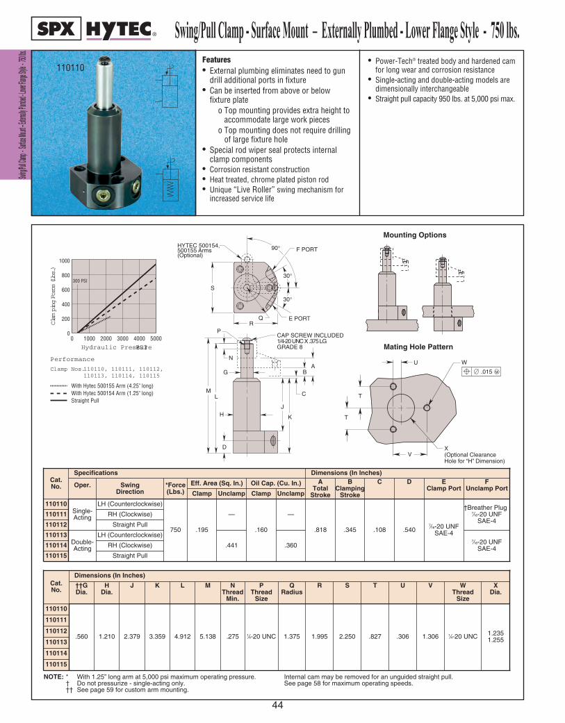
SSwwiinngg//PPuu
llll CCllaammpp
-- SSuurrffaaccee
MMoouunntt ––
EExxtteerrnnaallll
yy PPlluummbbee
dd -- LLoowwee
rr FFllaannggee
SSttyyllee -- 77
5500 llbbss..
44
Features• External plumbing eliminates need to gun
drill additional ports in fixture• Can be inserted from above or below
fixture plateo Top mounting provides extra height to
accommodate large work pieceso Top mounting does not require drilling
of large fixture hole• Special rod wiper seal protects internal
clamp components• Corrosion resistant construction• Heat treated, chrome plated piston rod• Unique “Live Roller” swing mechanism for
increased service life
• Power-Tech® treated body and hardened camfor long wear and corrosion resistance
• Single-acting and double-acting models aredimensionally interchangeable
• Straight pull capacity 950 lbs. at 5,000 psi max.
Swing/Pull Clamp - Surface Mount – Externally Plumbed - Lower Flange Style - 750 lbs.110110
300 PSI
0
1000
800
600
400
200
0
Clam
ping Force (Lbs.)
Performance
Clamp Nos.110110, 110111, 110112, 110113, 110114, 110115
With Hytec 500155 Arm (4.25" long)With Hytec 500154 Arm (1.25" long)Straight Pull
Hydraulic Pressure (PSI)1000 2000 3000 4000 5000
30°
30°
F PORT
Q E PORTR
90°
H
G
C
J
K
LM
HYTEC 500154,500155 Arms(Optional)
D
P
BA
N
S
CAP SCREW INCLUDED1/4-20 UNC X .375 LGGRADE 8
T
T
V
U
X (Optional Clearance Hole for “H” Dimension)
W
M .015
Mating Hole Pattern
Mounting Options
Cat.No.
Specifications Dimensions (In Inches)
Oper. SwingDirection
*Force(Lbs.)
Eff. Area (Sq. In.) Oil Cap. (Cu. In.) ATotal
Stroke
BClamping
Stroke
C D EClamp Port
Clamp Unclamp Clamp Unclamp
110110Single-Acting
LH (Counterclockwise)
750 .195
—
.160
—
.818 .345 .108 .5407⁄16-20 UNF
SAE-4
110111 RH (Clockwise)
110112 Straight Pull
110113Double-Acting
LH (Counterclockwise)
.441 .360110114 RH (Clockwise)
110115 Straight Pull
7⁄16-20 UNFSAE-4
†Breather Plug7⁄16-20 UNF
SAE-4
FUnclamp Port
Cat.No.
Dimensions (In Inches)
110110
.560 1.210 2.379 3.359 4.912 5.138 .275 1⁄4-20 UNC 1.375 1.995 2.250 .827
110111
110112
110113
110114
110115
.306 1.306 1⁄4-20 UNC 1.2351.255
XDia.
WThread
Size
VUTSRQRadius
PThread
Size
NThread
Min.
MLKJHDia.
††GDia.
NOTE: * With 1.25” long arm at 5,000 psi maximum operating pressure. † Do not pressurize - single-acting only.†† See page 59 for custom arm mounting.
Internal cam may be removed for an unguided straight pull. See page 58 for maximum operating speeds.
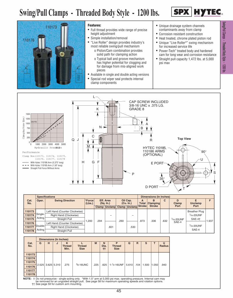
SS ww ii nn gg // PP uu ll ll CC ll aa mm pp ss -- TT hh rr ee aa dd ee dd BB oo dd yy SS tt yy ll ee -- 11 22 00 00 ll bb ss ..
45
Features:• Full thread provides wide range of precise
height adjustment • Simple installation/removal• “Live Roller” design provides industry’s
most reliable swing/pull mechanismo Piston/Cam combination provides
solid path for clamping actiono Typical ball and groove mechanism
has higher potential for clogging and for damage from mis-aligned work pieces
• Available in single and double acting versions• Special rod wiper seal protects internal
clamp components
• Unique drainage system channelscontaminants away from clamp
• Corrosion resistant construction• Heat treated, chrome plated piston rod• Unique “Live Roller®” swing mechanism
for increased service life• Power-Tech™ treated body and hardened
cam for long wear and corrosion resistance• Straight pull capacity 1,472 lbs. at 5,000
psi max
110173
110176
250 PSI
0
1500
1250
1000
750
500
250
0
Clam
ping Force (Lbs.)
Performance
Clamp Nos.110173, 110174, 110175,110176, 110177, 110178
With Hytec 110186 Arm (5.375" long)With Hytec 110185 Arm (1.50" long)Straight Pull Force Without Arms
Hydraulic Pressure (PSI)1000 2000 3000 4000 5000
E PORT
JQ
P
B
T
S
L
H G
M
F
C
K
NA
R
U
90°
35°
D PORT
HYTEC 110185,110186 ARMS(OPTIONAL)
Top View
NOTE: † Do not pressurize - single-acting only. *With 1.5" arm at 5,000 psi max. operating pressure. Internal cam maybe removed for an unguided straight pull. See page 58 for maximum operating speeds and rotation options.
†† See page 59 for custom arm mounting.
Dimensions (In Inches)
110173110174110175
2.525 3.625 5.310 .275 3⁄8-16UNC .225 .625 1-1⁄2-16UNF 5.610 .104 1.500 1.050 .940110176110177110178
Cat. No.
G H J KThread
Min.
LThread
Size
M NDia.††
PThread
Size
Q R S T URadius
110173 Left Hand (Counter Clockwise) Breather Plug110174 Single- Right Hand (Clockwise) – – 7⁄16-20UNF110175 Acting Straight Pull SAE-4†
1,200 .294 .260 .873 .336 .6327⁄16-20UNF 1.937
110176 Left Hand (Counter Clockwise) SAE-4
110177 Double- Right Hand (Clockwise) .601 .5307⁄16-20UNF
110178 Acting Straight Pull SAE-4
Cat. No.
Oper. Swing DirectionSpecifications Dimensions (In Inches)
*Force(Lbs.)
Clamp
Eff. Area(Sq. In.)
Oil Cap.(Cu. In.)
Unclamp Clamp
ATotal
Stroke
BClamping
Stroke
C DClampPort
EUnclamp
Port
F
Unclamp
E PORT
JQ
P
B
T
S
L
H G
M
F
C
K
NA
R
U
90°
35°
D PORT
HYTEC 110185,110186 ARMS(OPTIONAL)
CAP SCREW INCLUDED3/8-16 UNC x .375 LG.GRADE 8
Swing/Pull Clamps - Threaded Body Style - 1200 lbs.
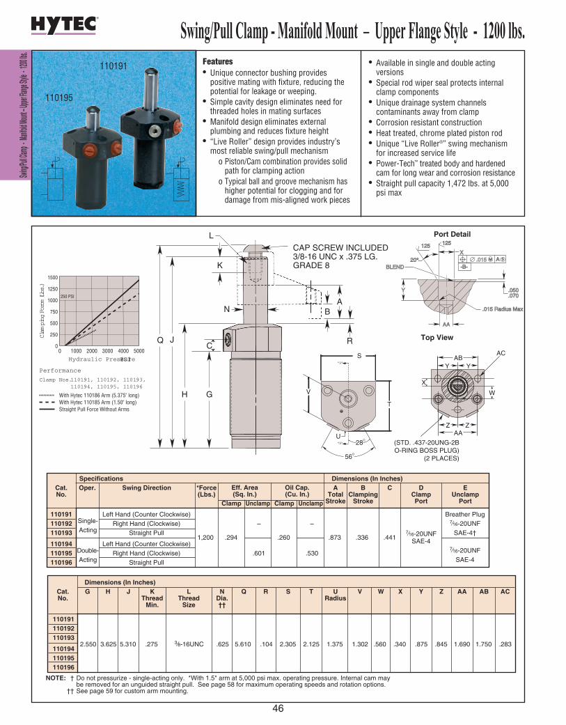
Features• Unique connector bushing provides
positive mating with fixture, reducing thepotential for leakage or weeping.
• Simple cavity design eliminates need forthreaded holes in mating surfaces
• Manifold design eliminates externalplumbing and reduces fixture height
• “Live Roller” design provides industry’smost reliable swing/pull mechanism
o Piston/Cam combination provides solidpath for clamping action
o Typical ball and groove mechanism has higher potential for clogging and for damage from mis-aligned work pieces
• Available in single and double actingversions
• Special rod wiper seal protects internalclamp components
• Unique drainage system channelscontaminants away from clamp
• Corrosion resistant construction• Heat treated, chrome plated piston rod• Unique “Live Roller®” swing mechanism
for increased service life• Power-Tech™ treated body and hardened
cam for long wear and corrosion resistance• Straight pull capacity 1,472 lbs. at 5,000
psi max
110191
110195
250 PSI
0
1500
1250
1000
750
500
250
0
Clam
ping Force (Lbs.)
Performance
Clamp Nos.110191, 110192, 110193,110194, 110195, 110196
With Hytec 110186 Arm (5.375" long)With Hytec 110185 Arm (1.50" long)Straight Pull Force Without Arms
Hydraulic Pressure (PSI)1000 2000 3000 4000 5000
ZZAA
W
X
YYAB
AC
(STD. .437-20UNG-2BO-RING BOSS PLUG)
(2 PLACES)
U
"A"
"A"
56O
28O
T
S
V
ZZAA
W
X
YYAB
AC
(STD. .437-20UNG-2BO-RING BOSS PLUG)
(2 PLACES)
U
"A"
"A"
56O
28O
T
S
V
Top View
NOTE: † Do not pressurize - single-acting only. *With 1.5" arm at 5,000 psi max. operating pressure. Internal cam maybe removed for an unguided straight pull. See page 58 for maximum operating speeds and rotation options.
†† See page 59 for custom arm mounting.
Dimensions (In Inches)
110191110192110193
2.550 3.625 5.310 .275 3⁄8-16UNC .625 5.610 .104 2.305 2.125 1.375 1.302 .560 .340 .875 .845 1.690 1.750 .283 110194110195110196
Cat. No.
G H J KThread
Min.
LThread
Size
NDia.††
Q R S T V W X Y Z AA AB ACURadius
110191 Left Hand (Counter Clockwise) Breather Plug110192 Single- Right Hand (Clockwise) – – 7⁄16-20UNF110193 Acting Straight Pull SAE-4†
1,200 .294 .260 .873 .336 .4417⁄16-20UNF
110194 Left Hand (Counter Clockwise) SAE-4
110195 Double- Right Hand (Clockwise) .601 .5307⁄16-20UNF
110196 Acting Straight Pull SAE-4
Cat. No.
Oper. Swing DirectionSpecifications Dimensions (In Inches)
*Force(Lbs.)
Clamp
Eff. Area(Sq. In.)
Oil Cap.(Cu. In.)
Unclamp Clamp
ATotal
Stroke
BClamping
Stroke
C DClampPort
EUnclamp
PortUnclamp
E PORT
JQ
B
T
S
L
H G
C
K
NA
R
U
90°
35°
D PORT
HYTEC 110185,110186 ARMS(OPTIONAL)
CAP SCREW INCLUDED3/8-16 UNC x .375 LG.GRADE 8
46
Swing/Pull Clamp - Manifold Mount – Upper Flange Style - 1200 lbs.S Sw wi i
n ng g/ /P Pu ul l
l l C Cl la am mp p
- - M Ma an n
i if fo ol ld d M Mo o
u un nt t – – U U
p pp pe er r F Fl l
a an ng ge e S St t
y yl le e - - 1 1
2 20 00 0 l lb bs s
. .
M S.015-B-
A
Y
125 125
X20°
BLEND
.050
.070
.015 Radius Max
AA
Port Detail
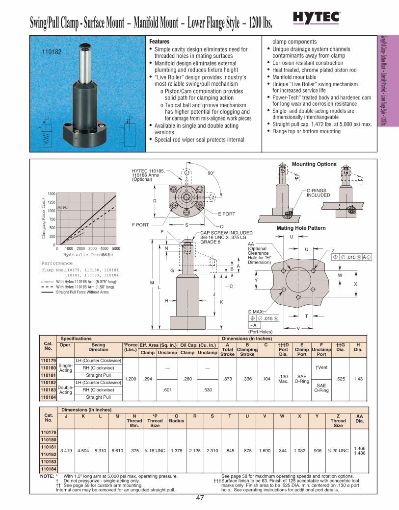
S Sw wi in ng g/ /P Pu ul ll l C Cl la am mp p - - S Su ur rf fa ac ce e M Mo ou un nt t – – E Ex xt te er rn na al ll ly y P Pl lu um mb be ed d - - L Lo ow we er r F Fl la an ng ge e S St ty yl le e - - 1 12 20 00 0 l lb bs s. .
47
Swing/Pull Clamp - Surface Mount – Manifold Mount – Lower Flange Style – 1200 lbs.
110184
Features• Simple cavity design eliminates need for
threaded holes in mating surfaces• Manifold design eliminates external
plumbing and reduces fixture height• “Live Roller” design provides industry’s
most reliable swing/pull mechanismo Piston/Cam combination provides
solid path for clamping actiono Typical ball and groove mechanism
has higher potential for clogging and for damage from mis-aligned work pieces
• Available in single and double actingversions
• Special rod wiper seal protects internal
clamp components• Unique drainage system channels
contaminants away from clamp• Corrosion resistant construction• Heat treated, chrome plated piston rod• Manifold mountable• Unique “Live Roller” swing mechanism
for increased service life• Power-Tech™ treated body and hardened cam
for long wear and corrosion resistance• Single- and double-acting models are
dimensionally interchangeable• Straight pull cap. 1,472 lbs. at 5,000 psi max.• Flange top or bottom mounting
250 PSI
0
1500
1250
1000
750
500
250
0
Clam
ping Force (Lbs.)
Performance
Clamp Nos.110179, 110180, 110181,110182, 110183, 110184
With Hytec 110186 Arm (5.375" long)With Hytec 110185 Arm (1.50" long)Straight Pull Force Without Arms
Hydraulic Pressure (PSI)1000 2000 3000 4000 5000
110182
Cat.No.
Dimensions (In Inches)J K L M N
ThreadMin.
*PThread
Size
QRadius
R S T U V
110179
3.419 4.504 5.310 5.610 .375 3⁄8-16 UNC 1.375 2.125 2.310 .845 .875 1.690
110180
110181
110182
110183
.344
W
1.032
X
.906
Y
1⁄4-20 UNC
ZThread
Size
1.4661.486
AADia.
Cat.No.
Specifications Dimensions (In Inches)Oper. Swing
Direction*Force(Lbs.)
Eff. Area (Sq. In.) Oil Cap. (Cu. In.) ATotal
Stroke
BClamping
Stroke
C †††DPortDia.
EClampPortClamp Unclamp Clamp Unclamp
110179Single-Acting
LH (Counter Clockwise)
1,200 .294
—
.260
—
.873 .336 .104 .130Max.
SAEO-Ring
110180 RH (Clockwise)
110181 Straight Pull
110182Double-Acting
LH (Counter Clockwise)
.601 .530110183 RH (Clockwise)
110184 Straight Pull
†Vent
SAEO-Ring
FUnclamp
Port
.625
††GDia.
1.43
HDia.
F PORT
E PORT
Q
R
S
90°HYTEC 110185,110186 Arms(Optional)
INCLUDEDO-RINGS
C
H
G
P
J
K
LM
BA
N
CAP SCREW INCLUDED3/8-16 UNC X .375 LGGRADE 8 AA
(Optional Clearance Hole for “H” Dimension)
Z
D MAX.
(Port Holes)
U
Y
V
U
X
W
T M .015
A
M .015 A L
Mating Hole Pattern
Mounting Options
NOTE: * With 1.5" long arm at 5,000 psi max. operating pressure. † Do not pressurize - single-acting only. †† See page 59 for custom arm mounting. Internal cam may be removed for an unguided straight pull.
See page 58 for maximum operating speeds and rotation options.†††Surface finish to be 63. Finish of 125 acceptable with concentric tool
marks only. Finish area to be .525 DIA. min. centered on .130 ø port hole. See operating instructions for additional port details.
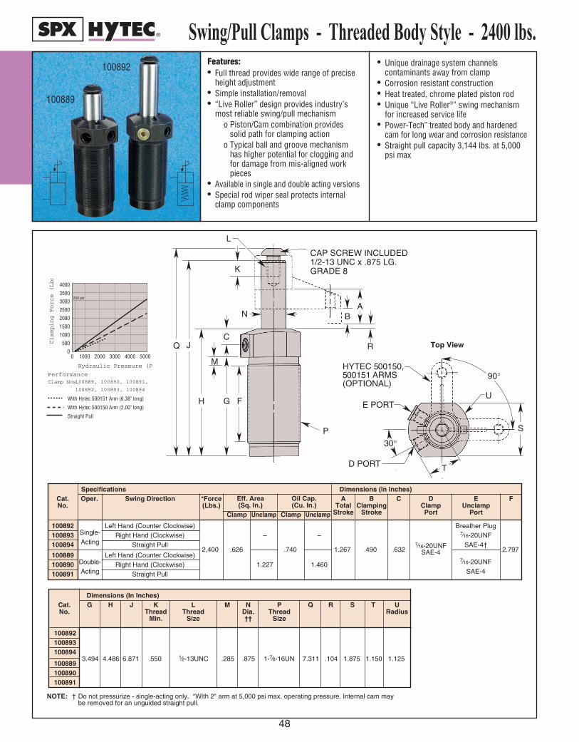
Swing
/Pull C
lamps
- Th
readed
Body
Style
- 240
0 lbs.
48
Features:• Full thread provides wide range of precise
height adjustment • Simple installation/removal• “Live Roller” design provides industry’s
most reliable swing/pull mechanismo Piston/Cam combination provides
solid path for clamping actiono Typical ball and groove mechanism
has higher potential for clogging and for damage from mis-aligned work pieces
• Available in single and double acting versions• Special rod wiper seal protects internal
clamp components
• Unique drainage system channelscontaminants away from clamp
• Corrosion resistant construction• Heat treated, chrome plated piston rod• Unique “Live Roller®” swing mechanism
for increased service life• Power-Tech™ treated body and hardened
cam for long wear and corrosion resistance• Straight pull capacity 3,144 lbs. at 5,000
psi max
Swing/Pull Clamps - Threaded Body Style - 2400 lbs.100892
100889
0 1000 2000 3000 4000 5000
4000
3500
3000
2500
2000
1500
1000
500
0
Hydraulic Pressure (PSI)
Clamping Force (Lbs.)
Performance
Clamp Nos. 100889, 100890, 100891
With Hytec 500151 Arm (6 inch)
With Hytec 500150 Arm (2 inch)
Straight Pull
0 1000 2000 3000 4000 5000
4000
3500
3000
2500
2000
1500
1000
500
0
Hydraulic Pressure (PSI)
Clamping Force (Lbs.)
PerformanceClamp Nos.100889, 100890, 100891,
100892, 100893, 100894
With Hytec 500151 Arm (6.38" long)
With Hytec 500150 Arm (2.00" long)
Straight Pull
250 psi
E PORT
JQ
P
B
T
S
L
H G
M
F
C
K
NA
R
U
90°
30°
D PORT
HYTEC 500150,500151 ARMS(OPTIONAL)
Cap screw included1/2-13 UNC x .875 Lg.Grade 8
Top View
NOTE: † Do not pressurize - single-acting only. *With 2" arm at 5,000 psi max. operating pressure. Internal cam maybe removed for an unguided straight pull.
Dimensions (In Inches)
100892100893100894
3.494 4.486 6.871 .550 1⁄2-13UNC .285 .875 1-7⁄8-16UN 7.311 .104 1.875 1.150 1.125100889100890100891
Cat. No.
G H J KThread
Min.
LThread
Size
M NDia.††
PThread
Size
Q R S T URadius
100892 Left Hand (Counter Clockwise) Breather Plug100893 Single- Right Hand (Clockwise) – – 7⁄16-20UNF100894 Acting Straight Pull SAE-4†
2,400 .626 .740 1.267 .490 .6327⁄16-20UNF 2.797
100889 Left Hand (Counter Clockwise) SAE-4
100890 Double- Right Hand (Clockwise) 1.227 1.4607⁄16-20UNF
100891 Acting Straight Pull SAE-4
Cat. No.
Oper. Swing DirectionSpecifications Dimensions (In Inches)
*Force(Lbs.)
Clamp
Eff. Area(Sq. In.)
Oil Cap.(Cu. In.)
Unclamp Clamp
ATotal
Stroke
BClamping
Stroke
C DClampPort
EUnclamp
Port
F
Unclamp
E PORT
JQ
P
B
T
S
L
H G
M
F
C
K
NA
R
U
90°
30°
D PORT
HYTEC 500150,500151 ARMS(OPTIONAL)
Cap screw included1/2-13 UNC x .875 Lg.Grade 8
CAP SCREW INCLUDED1/2-13 UNC x .875 LG.GRADE 8
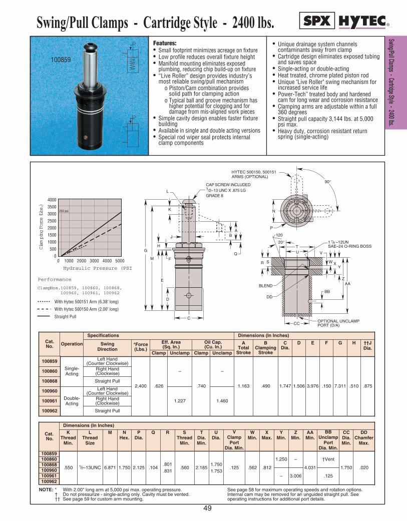
S Sw wi in ng g/ /P Pu ul ll l C Cl la am mp ps s - - C Ca ar rt tr ri id dg ge e S St ty yl le e - - 2 24 40 00 0 l lb bs s. .
49
Features:• Small footprint minimizes acreage on fixture• Low profile reduces overall fixture height• Manifold mounting eliminates exposed
plumbing, reducing chip build-up on fixture• “Live Roller” design provides industry’s
most reliable swing/pull mechanismo Piston/Cam combination provides
solid path for clamping actiono Typical ball and groove mechanism has
higher potential for clogging and fordamage from mis-aligned work pieces
• Simple cavity design enables faster fixturebuilding
• Available in single and double acting versions• Special rod wiper seal protects internal
clamp components
• Unique drainage system channelscontaminants away from clamp
• Cartridge design eliminates exposed tubing and saves space
• Single-acting or double-acting• Heat treated, chrome plated piston rod• Unique "Live Roller" swing mechanism for
increased service life• Power-Tech™ treated body and hardened
cam for long wear and corrosion resistance• Clamping arms are adjustable within a full
360 degrees• Straight pull capacity 3,144 lbs. at 5,000
psi max.• Heavy duty, corrosion resistant return
spring (single-acting)
Swing/Pull Clamps - Cartridge Style - 2400 lbs.
100859
0 1000 2000 3000 4000 5000
4000
3500
3000
2500
2000
1500
1000
500
0
Hydraulic Pressure (PSI)
Clam
ping Force (Lbs.)
Performance
Clamp Nos.100859, 100860, 100868,100960, 100961, 100962
With Hytec 500151 Arm (6.38" long)
With Hytec 500150 Arm (2.00" long)
Straight Pull
250 psi N
P
90 °
HYTEC 500150, 500151 ARMS (OPTIONAL)
1 7 / 8 –12UN SAE–24 O-RING BOSS
AA Z
Y X W
V
BB
OPTIONAL UNCLAMP POR T (D/A)
S R
CC
BLEND
DD
U T
20 °
120
CAP SCREW INCLUDED 1 /2 – 13 UNC X .875 LG GRADE 8
K
D
E
F
H
L
G
C
B A
Q M
J
NOTE: * With 2.00" long arm at 5,000 psi max. operating pressure. † Do not pressurize - single-acting only. Cavity must be vented.†† See page 59 for custom arm mounting.
See page 58 for maximum operating speeds and rotation options.Internal cam may be removed for an unguided straight pull. Seeoperating instructions for additional port details.
Cat. No. Operation
Specifications
ClampClamp Unclamp Unclamp
Dimensions (In Inches)
Swing Direction
*Force(Lbs.)
Eff. Area(Sq. In.)
Oil Cap.(Cu. In.)
ATotal
Stroke
BClamping
Stroke
CDia.
D E F G H ††JDia.
100859
Single-Acting
Left Hand(Counter Clockwise)
2,400 .626
–
.740
–
1.163 .490 1.747 1.506 3.976 .150 7.311 .510 .875
100860 Right Hand(Clockwise)
100868 Straight Pull
100960
Double-Acting
Left Hand(Counter Clockwise)
1.227 1.460100961 Right Hand(Clockwise)
100962 Straight Pull
Cat.No.
Dimensions (In Inches)
KThread
Min.
LThread
Size
M NHex.
PDia.
Q R SThread
Min.
TDia.Min.
UDia.
VClampPort
Dia. Min.
WMin.
XMax.
YMin.
ZMin.
AAMin.
BBUnclamp
PortDia. Min.
CCDia.Min.
DDChamfer
Max.
100859
.550 1⁄2–13UNC 6.871 1.750 2.125 .104.801.831
.560 2.185 .125 .562 .812
1.250 –
4.031
†Vent
1.750 .020
100860100868100960
– 3.006 .125100961100962
1.7501.753

SSwwiinngg//
PPuullll CCll
aammpp --
MMaanniiffoolldd
MMoouunntt
-- UUpppp
eerr FFllaanngg
ee SSttyyllee
-- 22440000
llbbss..
50
Features• Unique connector bushing provides
positive mating with fixture, reducing thepotential for leakage or weeping.
• Simple cavity design eliminates need forthreaded holes in mating surfaces
• Manifold design eliminates externalplumbing and reduces fixture height
• “Live Roller” design provides industry’smost reliable swing/pull mechanism
o Piston/Cam combination provides solidpath for clamping action
o Typical ball and groove mechanism has higher potential for clogging and for damage from mis-aligned work pieces
• Available in single and double actingversions
• Special rod wiper seal protects internalclamp components
• Unique drainage system channelscontaminants away from clamp
• Heat treated, chrome plated piston rod• Unique "Live Roller" swing mechanism for
increased service life• Power-Tech™ treated body and hardened
cam for long wear and corrosion resistance• Single and double-acting models• Straight pull capacity 3,144 lbs. at 5,000
psi max.
Swing/Pull Clamp - Manifold Mount - Upper Flange Style - 2400lbs.
100963
0 1000 2000 3000 4000 5000
4000
3500
3000
2500
2000
1500
1000
500
0
Hydraulic Pressure (PSI)
Clam
ping Force (Lbs.)
PerformanceClamp Nos. 100895, 100896, 100897,
100963, 100964, 100965
With Hytec 500151 Arm (6.38" long)
With Hytec 500150 Arm (2.00" long)
Straight Pull
250 psi
SUSEE PORT DET
AIL
T
-A-
M.015 A B MSM.015 A B MS
PN
Q
RV
BB
M S.015-B-
A
Y
125 125
X20°
BLEND
.050
.070
.015 Radius Max
AA
Port Detail
Mating Hole Pattern
NOTE: * With 2.00" long arm at 5,000 psi max. operating pressure. † Do not pressurize - single-acting only. †† See page 59 for custom arm mounting. Internal cam may be removed for an unguided straight pull.
See page 58 for maximum operating speeds and rotation options.†††Surface finish to be 63. Finish of 125 acceptable with concentric tool marks only. Finish area to be .500 DIA. min. centered on .250 DIA. port hole.See operating instructions for additional port details.
Specifications Dimensions (In Inches)Cat. No. Oper. Swing Direction *Force
(Lbs.)Eff. Area (Sq. In.) Oil Cap. (Cu. In.) A
TotalStroke
BClamping
Stroke
C Dia.
D E F G H J
Clamp Unclamp Clamp Unclamp
100895Single-Acting
Left Hand (Counter Clockwise)
.626
–
.740
–
1.163 .490 3.257 1.860 .104 3.491 3.380 .995
100896 Right Hand (Clockwise)
100897 Straight Pull
100963Double-Acting
Left Hand (Counter Clockwise)2,400
1.227 1.460100964 Right Hand (Clockwise)
100965 Straight Pull
Cat. No.
Dimensions (In Inches)K
ThreadMin.
LThread
Size
†† MDia.
NMounting
PMounting
QMounting
RMounting
SMounting
TThread
Size
UDia.
VUnclamp
Port Dia. Max.
W XDia.
Y AADia. Max.
BBMounting
100895
.5501⁄2-13UNC
.875 1.125 .562 2.125 1.062 1.3115⁄16-18UNC
1.8401.870
– †Vent.500.503
.640
.660.481
–
†††.250 – 1.311
C
D
HYTEC 5 00150, 5 00151 ARMS (OPTIONAL) 90 °
B
L
J
F
K
MA
E
CAP SCREW INCLUDED1/2–13UNC X .875 LGGRADE 8
G
H
W
100965100964100963100897100896
7.311

Features:• Full thread provides wide range of precise
height adjustment • Simple installation/removal• “Live Roller” design provides industry’s
most reliable swing/pull mechanismo Piston/Cam combination provides
solid path for clamping actiono Typical ball and groove mechanism
has higher potential for clogging and for damage from mis-aligned work pieces
• Available in single and double acting versions• Special rod wiper seal protects internal
clamp components
• Unique drainage system channelscontaminants away from clamp
• Heat treated, chrome plated piston rod• Unique "Live roller®" swing mechanism for
increased service life • Power-Tech™ treated body and hardened
cam for long wear and corrosion resistance• Clamping arms are adjustable anywhere
within a full 360 degrees• Straight pull capacity 3,144 lbs.
at 5,000 psi.
Swing/Pull Clamps - Threaded Body Style - 2400 lbs.100848
100841
With Hytec 500151 Arm (6.38" long)
With Hytec 500150 Arm (2.00" long)
Straight Pull
1000 2000 3000 4000 5000
4000
3500
3000
2500
2000
1500
1000
500
0
Hydraulic Pressure (PSI)
Clam
ping Force (Lbs.)
Performance
Clamp Nos.100841, 100842, 100848,100849, 100870, 100871
250 psi
HYTEC 500150,500151 ARMS(OPTIONAL)
90° P
BOLT INCLUDED1/2-20 UNF X .750 LGGRADE 8
BA
C
D
G
F
E
Q
M
N
HJ
K
L
R
HYTEC 500150,500151 ARMS(OPTIONAL)
90° P
BOLT INCLUDED1/2-20 UNF X .750 LGGRADE 8
BA
C
D
G
F
E
Q
M
N
HJ
K
L
R
Top View
NOTE: * With 2" arm at 5,000 psi max. operating pressure. Internal cam may be removed for an unguided straight pull.
† See page 59 for custom arm mounting.See page 58 for maximum operating speeds and rotation options.
FThread
Size
CBClamping
Stroke
ATotal
Stroke
Dimensions (In Inches)SpecificationsCat. No.
Swing Direction
100842
100870
Left Hand(Counter Clockwise)
Right Hand(Clockwise)
Left Hand(Counter Clockwise)
Straight Pull
Straight Pull
Right Hand(Clockwise)
2,400 .63 1.23
.74
1.21
1.46
2.36
1.163
1.938
.500
1.250
17⁄8 - 16 UN
D
3.188
4.688
1.252
EClampPort
1⁄8 NPTF
Clamp Unclamp Clamp Unclamp
Oil Cap. (Cu. In.)
Eff. Area(Sq. In.)
*Force(Lbs.)
100841
100848
100849
100871
Dimensions (In Inches)Cat. No.
GUnclamp
Port
H J K L MThread
Min.
NThread
Size
3.062
4.562
1⁄8 NPTF
3.740
2.240 4.312
5.812
6.575
8.810
.550 1⁄2 - 20UNF
PDia.
†QDia.
R
2.000 .875 .061
100842
100870
100841
100848
100849
100871
SS ww ii nn gg // PP uu ll ll CC ll aa mm pp ss -- TT hh rr ee aa dd ee dd BB oo dd yy SS tt yy ll ee -- 22 44 00 00 ll bb ss ..
51
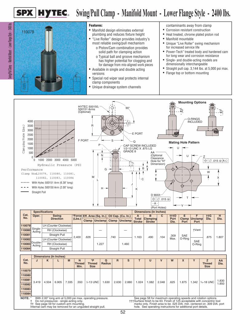
SSwwiinngg//
PPuullll CCll
aammpp --
MMaanniiffoolldd
MMoouunntt
-- LLooww
eerr FFllaanngg
ee SSttyyllee
-- 22440000
llbbss..
52
110084
Features:• Manifold design eliminates external
plumbing and reduces fixture height• “Live Roller” design provides industry’s
most reliable swing/pull mechanismo Piston/Cam combination provides
solid path for clamping actiono Typical ball and groove mechanism
has higher potential for clogging and for damage from mis-aligned work pieces
• Available in single and double actingversions
• Special rod wiper seal protects internalclamp components
• Unique drainage system channels
contaminants away from clamp• Corrosion resistant construction• Heat treated, chrome plated piston rod• Manifold mountable• Unique “Live Roller” swing mechanism
for increased service life• Power-Tech™ treated body and hardened cam
for long wear and corrosion resistance• Single- and double-acting models are
dimensionally interchangeable• Straight pull cap. 3,144 lbs. at 5,000 psi max.• Flange top or bottom mounting
0 1000 2000 3000 4000 5000
4000
3500
3000
2500
2000
1500
1000
500
0
Hydraulic Pressure (PSI)
C l a m p i n g F o r c e ( L b s . )
PerformanceClamp Nos.110079, 110080, 110081,
110082, 110083, 110084
With Hytec 500151 Arm (6.38" long)
With Hytec 500150 Arm (2.00" long)
Straight Pull
250 psi
110079
Swing/Pull Clamp - Manifold Mount - Lower Flange Style - 2400 lbs.
Cat.No.
Dimensions (In Inches)J K L M N
ThreadMin.
*PThread
Size
QRadius
R S T U V
110079
3.419 4.504 6.905 7.335 .550 1⁄2-13 UNC 1.630 2.630 2.880 1.024 1.082 2.048
110080
110081
110082
110083
.625
W
1.875
X
1.342
Y
5⁄16-18 UNC
ZThread
Size
1.8301.850
AADia.
Cat.No.
Specifications Dimensions (In Inches)Oper. Swing
Direction*Force(Lbs.)
Eff. Area (Sq. In.) Oil Cap. (Cu. In.) ATotal
Stroke
BClamping
Stroke
C †††DPortDia.
EClampPortClamp Unclamp Clamp Unclamp
110079Single-Acting
LH (Counter Clockwise)
2,400 .626
—
.740
—
1.163 .490 .104 .309Max.
SAEO-Ring
110080 RH (Clockwise)
110081 Straight Pull
110082Double-Acting
LH (Counter Clockwise)
1.227 1.460110083 RH (Clockwise)
110084 Straight Pull
†Vent
SAEO-Ring
FUnclamp
Port
.875
††GDia.
1.807
HDia.
F POR T
E POR T
Q
R
S
90 ° HYTEC 500150, 500151 Arms (Optional)
INCLUDEDO-RINGS
C
H
G
P
J
K
LM
BA
N
CAP SCREW INCLUDED 1/2-13 UNC X .875 LG GRADE 8 AA
(Optional Clearance Hole for “H” Dimension)
Z
D MAX.
(Port Holes)
U
Y
V
U
X
W
T M .015
A
M .015 A L
Mating Hole Pattern
Mounting Options
NOTE: * With 2.00" long arm at 5,000 psi max. operating pressure. † Do not pressurize - single-acting only. †† See page 59 for custom arm mounting. Internal cam may be removed for an unguided straight pull.
See page 58 for maximum operating speeds and rotation options.†††Surface finish to be 63. Finish of 125 acceptable with concentric tool
marks only. Finish area to be .525 DIA. min. centered on .309 DIA. port hole. See operating instructions for additional port details.
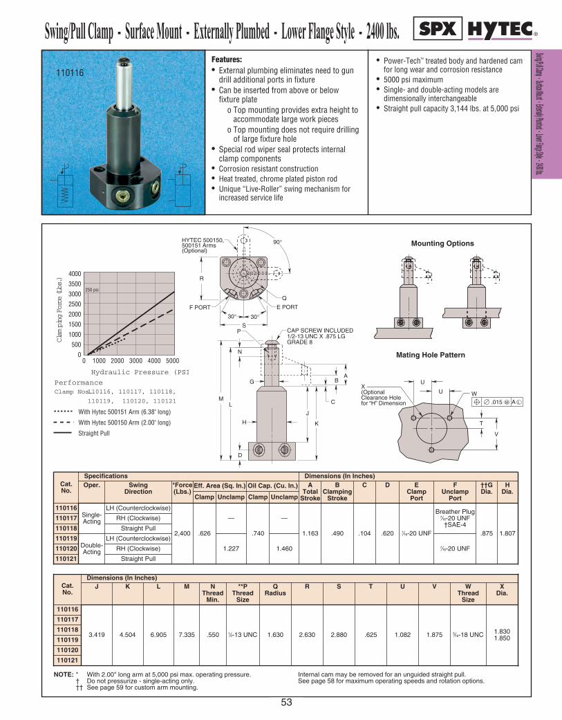
Features:• External plumbing eliminates need to gun
drill additional ports in fixture• Can be inserted from above or below
fixture plateo Top mounting provides extra height to
accommodate large work pieceso Top mounting does not require drilling
of large fixture hole• Special rod wiper seal protects internal
clamp components• Corrosion resistant construction• Heat treated, chrome plated piston rod• Unique “Live-Roller” swing mechanism for
increased service life
• Power-Tech™ treated body and hardened camfor long wear and corrosion resistance
• 5000 psi maximum• Single- and double-acting models are
dimensionally interchangeable• Straight pull capacity 3,144 lbs. at 5,000 psi
0 1000 2000 3000 4000 5000
4000
3500
3000
2500
2000
1500
1000
500
0
Hydraulic Pressure (PSI)
C l a m p i n g F o r c e ( L b s . )
PerformanceClamp Nos.110116, 110117, 110118,
110119, 110120, 110121
With Hytec 500151 Arm (6.38" long)
With Hytec 500150 Arm (2.00" long)
Straight Pull
250 psi
110116
Swing/Pull Clamp - Surface Mount - Externally Plumbed - Lower Flange Style - 2400 lbs.
Cat.No.
Specifications Dimensions (In Inches)Oper. Swing
Direction*Force(Lbs.)
Eff. Area (Sq. In.) Oil Cap. (Cu. In.) ATotal
Stroke
BClamping
Stroke
C D EClampPortClamp Unclamp Clamp Unclamp
110116Single-Acting
LH (Counterclockwise)
2,400 .626
—
.740
—
1.163 .490 .104 .620 7⁄16-20 UNF
110117 RH (Clockwise)
110118 Straight Pull
110119Double-Acting
LH (Counterclockwise)
1.227 1.460110120 RH (Clockwise)
110121 Straight Pull
7⁄16-20 UNF
Breather Plug7⁄16-20 UNF
†SAE-4
FUnclamp
Port
.875
††GDia.
1.807
HDia.
Cat.No.
Dimensions (In Inches)J K L M N
ThreadMin.
**PThread
Size
QRadius
R S T U V
110116
3.419 4.504 6.905 7.335 .550 1⁄2-13 UNC 1.630 2.630 2.880 .625 1.082 1.875
110117
110118
110119
110120
110121
5⁄16-18 UNC
WThread
Size
1.8301.850
XDia.
30 ° 30 ° F POR T
Q
E POR T
R
S
90 ° HYTEC 500150, 500151 Arms (Optional)
C
H
G
P
J
K
LM
BA
N
D
CAP SCREW INCLUDED 1/2-13 UNC X .875 LG GRADE 8
V
T
X (Optional Clearance Hole for “H” Dimension
W
U
U
M .015 A L
Mating Hole Pattern
Mounting Options
NOTE: * With 2.00" long arm at 5,000 psi max. operating pressure. † Do not pressurize - single-acting only. †† See page 59 for custom arm mounting.
Internal cam may be removed for an unguided straight pull.See page 58 for maximum operating speeds and rotation options.
S Sw wi in ng g/ /P Pu ul ll l C Cl la am mp p - - S Su ur rf fa ac ce e M Mo ou un nt t - - E Ex xt te er rn na al ll ly y P Pl lu um mb be ed d - - L Lo ow we er r F Fl la an ng ge e S St ty yl le e - - 2 24 40 00 0 l lb bs s. .
53
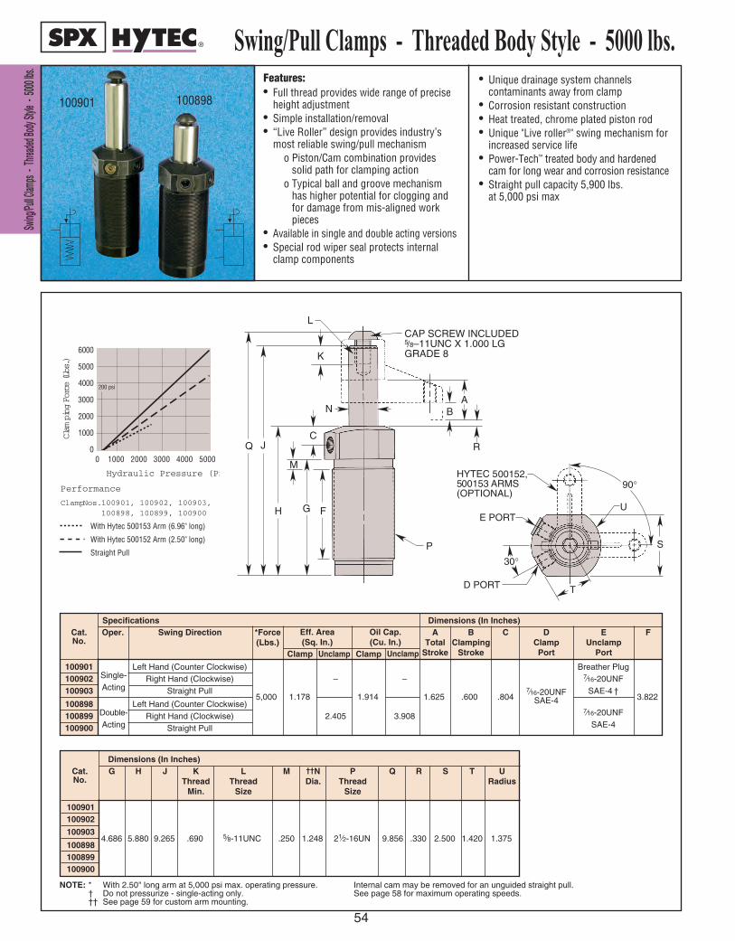
SS wwii nn gg
// PP uull ll CC
ll aa mmpp ss
-- TT hh
rr ee aadd ee dd
BB oodd yy
SS tt yyll ee
-- 5500 00
00 ll bbss ..
54
Features:• Full thread provides wide range of precise
height adjustment • Simple installation/removal• “Live Roller” design provides industry’s
most reliable swing/pull mechanismo Piston/Cam combination provides
solid path for clamping actiono Typical ball and groove mechanism
has higher potential for clogging and for damage from mis-aligned work pieces
• Available in single and double acting versions• Special rod wiper seal protects internal
clamp components
• Unique drainage system channelscontaminants away from clamp
• Corrosion resistant construction• Heat treated, chrome plated piston rod• Unique "Live roller®" swing mechanism for
increased service life• Power-Tech™ treated body and hardened
cam for long wear and corrosion resistance• Straight pull capacity 5,900 lbs.
at 5,000 psi max
Swing/Pull Clamps - Threaded Body Style - 5000 lbs.
100901 100898
0 1000 2000 3000 4000 5000
6000
5000
4000
3000
2000
1000
0
Hydraulic Pressure (PSI)
Clam
ping Force (Lbs.)
Performance
Clamp Nos.100901, 100902, 100903,100898, 100899, 100900
With Hytec 500153 Arm (6.96" long)
With Hytec 500152 Arm (2.50" long)
Straight Pull
200 psi
E PORT
JQ
P
B
T
S
L
H G
M
F
C
K
NA
R
CAP SCREW INCLUDED5/8–11UNC X 1.000 LGGRADE 8
U
90°
30°
D PORT
HYTEC 5500153 ARMS(OPTIONAL)
00152,
E PORT
JQ
P
B
T
S
L
H G
M
F
C
K
NA
R
CAP SCREW INCLUDED5/8–11UNC X 1.000 LGGRADE 8
U
90°
30°
D PORT
HYTEC 5500153 ARMS(OPTIONAL)
00152,
100901 Left Hand (Counter Clockwise) Breather Plug100902 Single- Right Hand (Clockwise) – – 7⁄16-20UNF100903 Acting Straight Pull SAE-4 †
5,000 1.178 1.914 1.625 .600 .8047⁄16-20UNF 3.822
100898 Left Hand (Counter Clockwise) SAE-4
100899 Double- Right Hand (Clockwise) 2.405 3.9087⁄16-20UNF
100900 Acting Straight Pull SAE-4
Cat. No.
Oper. Swing DirectionSpecifications Dimensions (In Inches)
*Force(Lbs.)
Clamp
Eff. Area(Sq. In.)
Oil Cap.(Cu. In.)
Unclamp Clamp
ATotal
Stroke
BClamping
Stroke
C DClampPort
EUnclamp
Port
F
Unclamp
Dimensions (In Inches)
100901100902
1009034.686 5.880 9.265 .690 5⁄8-11UNC .250 1.248 21⁄2-16UN 9.856 .330 2.500 1.420 1.375
100898100899100900
Cat. No.
G H J KThread
Min.
LThread
Size
M ††NDia.
PThread
Size
Q R S T URadius
NOTE: * With 2.50" long arm at 5,000 psi max. operating pressure. † Do not pressurize - single-acting only. †† See page 59 for custom arm mounting.
Internal cam may be removed for an unguided straight pull. See page 58 for maximum operating speeds.
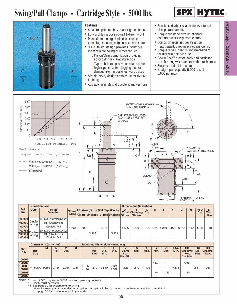
Features:• Small footprint minimizes acreage on fixture• Low profile reduces overall fixture height• Manifold mounting eliminates exposed
plumbing, reducing chip build-up on fixture• “Live Roller” design provides industry’s
most reliable swing/pull mechanismo Piston/Cam combination provides
solid path for clamping actiono Typical ball and groove mechanism has
higher potential for clogging and fordamage from mis-aligned work pieces
• Simple cavity design enables faster fixturebuilding
• Available in single and double acting versions
• Special rod wiper seal protects internalclamp components
• Unique drainage system channelscontaminants away from clamp
• Corrosion resistant construction• Heat treated, chrome plated piston rod• Unique "Live Roller" swing mechanism
for increased service life• Power TechTM treated body and hardened
cam for long wear and corrosion resistance• Single-and double-acting• Straight pull capacity 5,900 lbs. at
5,000 psi max
Swing/Pull Clamps - Cartridge Style - 5000 lbs.
100904
0 1000 2000 3000 4000 5000
6000
5000
4000
3000
2000
1000
0
Hydraulic Pressure (PSI)
Clam
ping Force (Lbs.)
Performance
Clamp Nos.100904, 100905, 100906
With Hytec 500153 Arm (7.00" long)
With Hytec 500152 Arm (2.50" long)
Straight Pull
200 psi
N
P
90 °
HYTEC 500152, 500153 ARMS (OPTIONAL)
2 1 / 2 –12UNC SAE–32 O-RING BOSS
AA Z
Y X W
V
BB
OPTIONAL UNCLAMP POR T (D/A)
S R
CC
BLEND
DD
U T
20 °
120
CAP SCREW INCLUDED 5 / 8 – 1 1UNC X 1.000 LG GRADE 8
K
D
E
F
H
L
G
C
B A
Q M
J
Dimensions (In Inches)Cat. No.
Swing Direction *Force
(Lbs.)Eff. Area (Sq. In.) Oil Cap. (Cu. In.) A
TotalStroke
BClamping
Stroke
CDia.
D E F G H †† J Dia.
100904 LH (Counterclockwise)
5,000 1.178 1.914 1.625 .600 2.372 2.162 5.340 .160 9.856 .540 1.248100906 Straight Pull
100989 RH (Clockwise)
NOTE: * With 2.50" long arm at 5,000 psi max. operating pressure. † Cavity must be vented.†† See page 59 for custom arm mounting.
Internal cam may be removed for an unguided straight pull. See operating instructions for additional port details.See page 58 for maximum operating speeds.
Cat. No.
Dimensions (In Inches)L
Thd.Size
M NHex.
PDia.
Q R SMin.Thd.
TDia.Min.
UDia.
VClampPort
Dia. Min.
WMin.
XMax.
YMin.
ZMin.
† AAMin.
BBUnclamp
PortDia. Min.
CCDia.Min.
100904
5⁄8-11UNC 9.265 2.125 2.750 .3301.1361.166
.870 2.8102.3752.378
.125 .870 1.136
1.584 —
5.378
*Vent
2.374
DDChamfer
Max.
.020
— 4.138 .125
Mounting Dimensions (In Inches)
KThd.Size
.740
Specifications
Single-Acting
Oper.
100905
100988
100990
Double-Acting
— —
Clamp Unclamp
2.405
Clamp Unclamp
RH (Clockwise)
LH (Counterclockwise)
Straight Pull3.908
100990100989100988100906100905
SS ww ii nn gg // PP uu ll ll CC ll aa mm pp ss -- CC aa rr tt rr ii dd gg ee SS tt yy ll ee -- 55 00 00 00 ll bb ss ..
55

SSwwiinngg//
PPuullll CCll
aammpp --
MMaanniiffoolldd
MMoouunntt
-- LLooww
eerr FFllaanngg
ee SSttyyllee
-- 55000000
llbbss..
56
Features:• Manifold design eliminates external
plumbing and reduces fixture height• “Live Roller” design provides industry’s
most reliable swing/pull mechanismo Piston/Cam combination provides
solid path for clamping actiono Typical ball and groove mechanism
has higher potential for clogging and for damage from mis-aligned work pieces
• Available in single and double actingversions
• Special rod wiper seal protects internalclamp components
• Unique drainage system channels
contaminants away from clamp• Corrosion resistant construction• Heat treated, chrome plated piston rod• Manifold mountable• Unique “Live Roller” swing mechanism
for increased service life• Power-Tech™ treated body and hardened cam
for long wear and corrosion resistance• Single- and double-acting models are
dimensionally interchangeable
Cat.No.
Specifications Dimensions (In Inches)Oper. Swing
Direction*Force(Lbs.)
Eff. Area (Sq. In.) Oil Cap. (Cu. In.) ATotal
Stroke
BClamping
Stroke
C DPortDia.
EClampPortClamp Unclamp Clamp Unclamp
110089Single-Acting
LH (Counterclockwise)
5,000 1.178
—
1.914
—
1.625 .600 .330 .340MAX.
7⁄16-20UNFSAE-4
110090 RH (Clockwise)
110091 Straight Pull
110092Double-Acting
LH (Counterclockwise)
2.405 3.908110093 RH (Clockwise)
110094 Straight Pull
7⁄16-20UNFSAE-4
Breather Plug7⁄16-20UNFSAE-4†
FUnclamp
Port
1.248
††GDia.
2.425
HDia.
Cat.No.
Dimensions (In Inches)J K L M N
ThreadMin.
PThread
Size
Q R S T U VDia.
110089
4.737
5.917
5.730
9.297
9.110
9.887
9.700
.690 5⁄8-11 UNC 3.305 2.750 .570 1.085 .408 2.4422.462
110090
110091
110092
110093
110094
5⁄16-18 UNC
WThread
Size
NOTE: * With 2.50" long arm at 5,000 psi max. operating pressure. † Do not pressurize - single-acting only. †† See page 59 for custom arm mounting.
Internal cam may be removed for an unguided straight pull.See page 58 for maximum operating speeds and rotation options.
110089
INCLUDEDO-RINGS
Mounting Options
Mating Hole Pattern
0 1000 2000 3000 4000 5000
6000
5000
4000
3000
2000
1000
0
Hydraulic Pressure (PSI)
Clam
ping Force (Lbs.)
Performance
Clamp Nos.100904, 100905, 100906
With Hytec 500153 Arm (7.00" long)
With Hytec 500152 Arm (2.50" long)
Straight Pull
200 psi
G
M
L
KH
R
Q
J
P
N
C
BA
V
WTT
T
T (OPTIONAL CLEARANCEHOLE FOR "H" DIMENSION
M.015 A L
S
S
Hytec 500153, 500152 Arms(optional)
D
G
M
L
KH
E PORTF PORT
R
Q
J
P
N
C
BA
V
WTT
T
T (OPTIONAL CLEARANCEHOLE FOR "H" DIMENSION
M.015 A L
SS
D
Hytec 500153, 500152 Arms(optional)
Swing/Pull Clamp - Manifold Mount - Lower Flange Style - 5000 lbs.

Features:• External plumbing eliminates need to gun
drill additional ports in fixture• Can be inserted from above or below
fixture plateo Top mounting provides extra height to
accommodate large work pieceso Top mounting does not require drilling
of large fixture hole
• Special rod wiper seal protects internalclamp components
• Corrosion resistant construction• Heat treated, chrome plated piston rod• Power-Tech® treated body and hardened cam
for long wear and corrosion resistance
Cat.No.
Specifications Dimensions (In Inches)Oper. Swing
Direction*Force(Lbs.)
Eff. Area (Sq. In.) Oil Cap. (Cu. In.) ATotal
Stroke
BClamping
Stroke
C D EClampPortClamp Unclamp Clamp Unclamp
110095Single-Acting
LH (Counterclockwise)
5,000 1.178
—
1.914
—
1.625 .600 .330 .5007⁄16-20 UNF
SAE-4
110096 RH (Clockwise)
110097 Straight Pull
110098Double-Acting
LH (Counterclockwise)
2.405 3.908110099 RH (Clockwise)
110100 Straight Pull
7⁄16-20 UNFSAE-4
†Breather Plug
7⁄16-20 UNFSAE-4
FUnclamp
Port
1.248
††GDia.
2.425
HDia.
Cat.No.
Dimensions (In Inches)J K L M N
ThreadMin.
PThread
Size
QRadius
R S T VDia.
110095
4.737
5.917
5.730
9.297
9.110
9.887
9.700
.690 5⁄8-11 UNC 3.305 2.750 .570 1.085 2.4422.462
110096
110097
110098
110099
110100
5⁄16-18 UNC
WThread
Size
NOTE: * With 2.50" long arm at 5,000 psi max. operating pressure. † Do not pressurize - single-acting only. †† See page 59 for custom arm mounting.
Internal cam may be removed for an unguided straight pull.See page 58 for maximum operating speeds and rotation options.
110095
Swing/Pull Clamp - Surface Mount - Externally Plumbed - Lower Flange Style - 5000 lbs.
Mating Hole Pattern
Mounting Options
0 1000 2000 3000 4000 5000
6000
5000
4000
3000
2000
1000
0
Hydraulic Pressure (PSI)
Clam
ping Force (Lbs.)
Performance
Clamp Nos. 110095, 110096, 110097 110098, 110099, 110100
With Hytec 500153 Arm (7.00" long)
With Hytec 500152 Arm (2.50" long)
Straight Pull
200 psi
G
M
L
KH
E PORTF PORT
R
Q
J
P
N
C
BA
V
WTT
T
T (OPTIONAL CLEARANCEHOLE FOR "H" DIMENSION
M.015 A L
SS
D
Hytec 500153, 500152 Arms(optional)
G
M
L
KH
E PORTF PORT
R
Q
J
P
N
C
BA
V
WTT
T
T (OPTIONAL CLEARANCEHOLE FOR "H" DIMENSION
M.015 A L
SS
D
Hytec 500153, 500152 Arms(optional)
S Sw wi in ng g/ /P Pu ul ll l C Cl la am mp p - - S Su ur rf fa ac ce e M Mo ou un nt t - - E Ex xt te er rn na al ll ly y P Pl lu um mb be ed d - - L Lo ow we er r F Fl la an ng ge e S St ty yl le e - - 5 50 00 00 0 l lb bs s. .
57
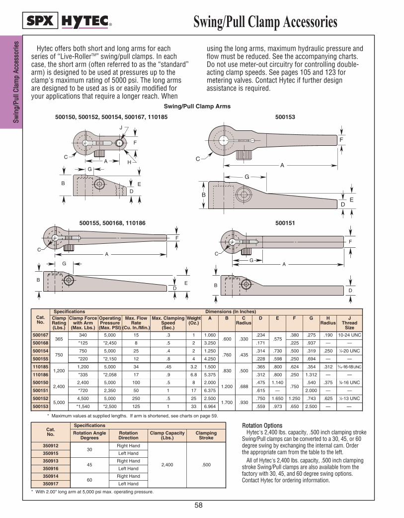
SSwwiinn
gg//PPuu
llll CCll
aammpp
AAccccee
ssssoorr
iieess
58
RRoottaattiioonn OOppttiioonnssHytec's 2,400 lbs. capacity, .500 inch clamping stroke
Swing/Pull clamps can be converted to a 30, 45, or 60degree swing by exchanging the internal cam. Orderthe appropriate cam from the table to the left.
All of Hytec's 2,400 lbs. capacity, .500 inch clampingstroke Swing/Pull clamps are also available from thefactory with 30, 45, and 60 degree swing options.Contact Hytec for ordering information.
* With 2.00" long arm at 5,000 psi max. operating pressure.
* Maximum values at supplied lengths. If arm is shortened, see charts on page 59.
Hytec offers both short and long arms for eachseries of “Live-RollerTM” swing/pull clamps. In eachcase, the short arm (often referred to as the “standard”arm) is designed to be used at pressures up to theclamp's maximum rating of 5000 psi. The long armsare designed to be used as is or easily modified foryour applications that require a longer reach. When
using the long arms, maximum hydraulic pressure andflow must be reduced. See the accompanying charts.Do not use meter-out circuitry for controlling double-acting clamp speeds. See pages 105 and 123 formetering valves. Contact Hytec if further designassistance is required.
Swing/Pull Clamp Arms
A
D
H
F
J
C
E
G
B
DE
B
G
A
F
C
F
G
D
B
AC
E
DB
GA
F
C
500155, 500168, 110186 500151
500153500150, 500152, 500154, 500167, 110185
Swing/Pull Clamp Accessories
Cat.No.
Specifications
Rotation AngleDegrees
RotationDirection
Clamp Capacity(Lbs.)
Clamping Stroke
35091230
Right Hand
2,400 .500
350915 Left Hand
35091345
Right Hand
350916 Left Hand
35091460
Right Hand
350917 Left Hand
Cat.No.
Specifications Dimensions (In Inches)ClampRating(Lbs.)
Clamp Forcewith Arm
(Max. Lbs.)
OperatingPressure(Max. PSI)
Max. FlowRate
(Cu. In./Min.)
Max. ClampingSpeed(Sec.)
Weight(Oz.)
A B CRadius
D E F
500167365
340 5,000 15 .3 1 1.060.600 .330
.234.575
.380
500168 *125 *2,450 8 .5 2 3.250 .171 .225
500154750
750 5,000 25 .4 2 1.250.760 .435
.314 .730 .500
500155 *220 *2,150 12 .8 4 4.250 .228 .598 .250
5001502,400
2,400 5,000 100 .5 8 2.0001.200 .688
.475 1.140.750
500151 *720 2,350 50 1 17 6.375 .615 —
5,0004,500 5,000 250 .5 25 2.500
1.700 .930.750 1.650 1.250 .743
2.000
.540
.694
.319
.937
.275
G
.625
—
.375
—
.250
—
.190
HRadius
1⁄2-13 UNC
—
3⁄8-16 UNC
—
1⁄4-20 UNC
—
10-24 UNC
JThread
Size
500152
500153 *1,540 *2,500 125 1 33 6.964 .559 .973 .650 2.500 — —
110185 1,200 5,000 34 .45 3.2 1.500.830 .500
.365 .800 .624
110186 *335 *2,058 17 .9 6.8 5.375 .312 .800 .250 1.312
.354
—
.312
—
5⁄16-16-18 UNC1,200
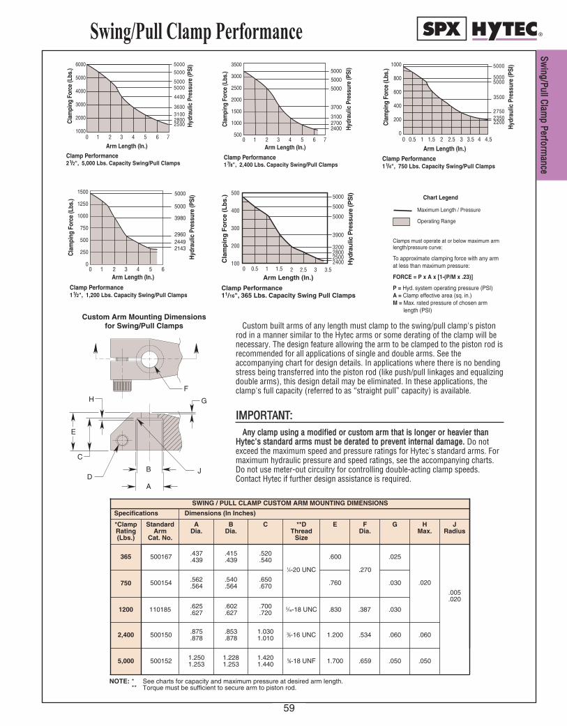
Swing/Pull Clamp Performance
0 1 2 3 4 5 6 7
6000
5000
4000
3000
2000
1000
Arm Length (In.)
Cla
mpi
ng F
orce
(Lbs
.)
Hyd
raul
ic P
ress
ure
(PSI
)
Clamp Performance2 1/2", 5,000 Lbs. Capacity Swing/Pull Clamps
5000
5000
50005000
4400
3600310028002500
0 0.5 1 1.5 2 2.5 3 3.5 4 4.5
1000
800
600
400
200
0
Arm Length (In.)
Cla
mpi
ng F
orce
(Lbs
.)
Hyd
raul
ic P
ress
ure
(PSI
)
Clamp Performance1 1/4", 750 Lbs. Capacity Swing/Pull Clamps
5000
50005000
3500
275023502200
Cla
mp
ing
Fo
rce
(Lb
s.)
Arm Length (In.)0 0.5 1 1.5 2 2.5 3 3.5
100
200
300
400
5005000
5000
5000
3900
3200280025002400 H
ydra
ulic
Pre
ssur
e (P
SI)
Clamp Performance11/16", 365 Lbs. Capacity Swing Pull Clamps
Clamp Performance1 7/8", 2,400 Lbs. Capacity Swing/Pull Clamps
0 1 2 3 4 5 6 7
3500
3000
2500
2000
1500
1000
500
Arm Length (In.)
Cla
mpi
ng F
orce
(Lbs
.)
Hyd
raul
ic P
ress
ure
(PSI
)
5000
5000
5000
3700
310027002400
Maximum Length / Pressure
Operating Range
Clamps must operate at or below maximum armlength/pressure curve:
To approximate clamping force with any armat less than maximum pressure:
FORCE = P x A x [1-(P/M x .23)]
P = Hyd. system operating pressure (PSI)A = Clamp effective area (sq. in.)M = Max. rated pressure of chosen arm
length (PSI)
Chart Legend
Custom built arms of any length must clamp to the swing/pull clamp's pistonrod in a manner similar to the Hytec arms or some derating of the clamp will benecessary. The design feature allowing the arm to be clamped to the piston rod isrecommended for all applications of single and double arms. See theaccompanying chart for design details. In applications where there is no bendingstress being transferred into the piston rod (like push/pull linkages and equalizingdouble arms), this design detail may be eliminated. In these applications, theclamp's full capacity (referred to as “straight pull” capacity) is available.
IIMMPPOORRTTAANNTT:: AAnnyy ccllaammpp uussiinngg aa mmooddiiffiieedd oorr ccuussttoomm aarrmm tthhaatt iiss lloonnggeerr oorr hheeaavviieerr tthhaann
HHyytteecc''ss ssttaannddaarrdd aarrmmss mmuusstt bbee ddeerraatteedd ttoo pprreevveenntt iinntteerrnnaall ddaammaaggee.. Do notexceed the maximum speed and pressure ratings for Hytec's standard arms. Formaximum hydraulic pressure and speed ratings, see the accompanying charts.Do not use meter-out circuitry for controlling double-acting clamp speeds.Contact Hytec if further design assistance is required.
C
E
H
J D
B
A
F
G
Custom Arm Mounting Dimensionsfor Swing/Pull Clamps
Dimensions (In Inches)
Standard Arm
Cat. No.
A Dia.
B Dia.
C **D Thread
Size
E F Dia.
G H Max.
J Radius
365 500167 .437.439
.415
.439.520.540
1⁄4-20 UNC
.600
.270
.025
.020
.005
.020
NOTE: * See charts for capacity and maximum pressure at desired arm length.** Torque must be sufficient to secure arm to piston rod.
Specifications
SWING / PULL CLAMP CUSTOM ARM MOUNTING DIMENSIONS
2,400 500150 .875.878
.853
.8781.0301.010
3⁄8-16 UNC 1.200 .534 .060 .060
750 500154 .562.564
.540
.564.650.670 .760 .030
1200 110185 .625.627
.602
.627.700.720
5⁄16-18 UNC .830 .387 .030
5,000 500152 1.2501.253
1.2281.253
1.4201.440
5⁄8-18 UNF 1.700 .659 .050 .050
*ClampRating(Lbs.)
Clamp Performance1 1/2", 1,200 Lbs. Capacity Swing/Pull Clamps
0 1 2 3 4 5 6
1500
1250
1000
750
500
250
0
Arm Length (In.)
Cla
mpi
ng F
orce
(Lbs
.)
Hyd
raul
ic P
ress
ure
(PSI
)5000
5000
3980
296024492143
SSwwiinngg//PPuullll CCllaamm
pp PPeerrffoorrmmaannccee
59
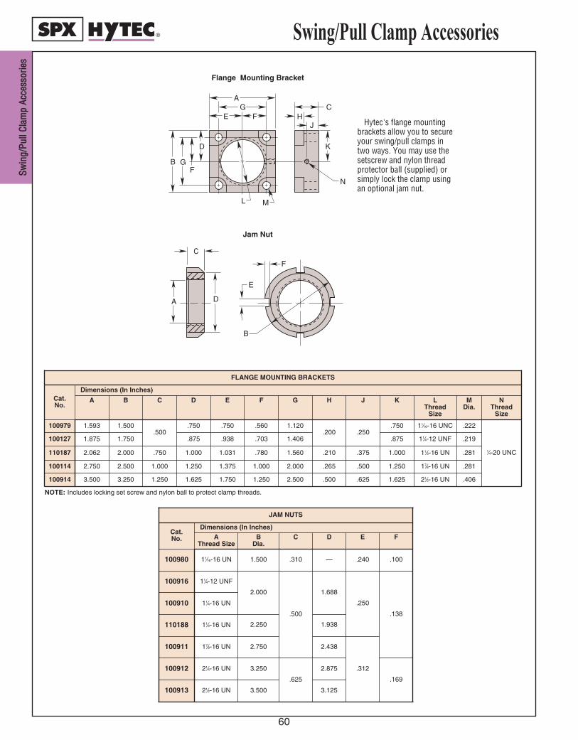
SSwwiinn
gg//PPuu
llll CCll
aammpp
AAccccee
ssssoorr
iieess
60
Swing/Pull Clamp Accessories
Hytec's flange mountingbrackets allow you to secureyour swing/pull clamps intwo ways. You may use thesetscrew and nylon threadprotector ball (supplied) orsimply lock the clamp usingan optional jam nut.
B
N
M
D
G F
L
F G
A
K
J H
C E
Flange Mounting Bracket
Jam Nut
C
D A
E
F
B
NOTE: Includes locking set screw and nylon ball to protect clamp threads.
JAM NUTS
Cat. No. A
Thread SizeB
Dia.C D E F
100980 11⁄16-16 UN 1.500 .310 — .240 .100
FLANGE MOUNTING BRACKETS
Cat. No.
Dimensions (In Inches)
A B C D E F G H J K LThread
Size
MDia.
100979 1.593 1.500.500
.750 .750 .560 1.120.200 .250
.750 11⁄16-16 UNC .222
100127 1.875 1.750 .875 .938 .703 1.406 .875 11⁄4-12 UNF .219
100114 2.750 2.500 1.000 1.250 1.375 1.000 2.000 .265 .500 1.250 17⁄8-16 UN .281
100914 3.500 3.250 1.250 1.625 1.750 1.250 2.500 .500 .625 1.625 21⁄2-16 UN .406
1⁄4-20 UNC
NThread
Size
Dimensions (In Inches)
100912 21⁄4-16 UN 3.250
.625
2.875
.169
100910 11⁄4-16 UN
110188 11⁄2-16 UN
100913 21⁄2-16 UN 3.500 3.125
100916 11⁄4-12 UNF
2.000
.500
1.688
.250
.138
100911 17⁄8-16 UN 2.438
1.938
.312
2.750
2.250
110187 2.062 2.000 .750 1.000 1.031 .780 1.560 .210 .375 1.000 11⁄2-16 UN .281
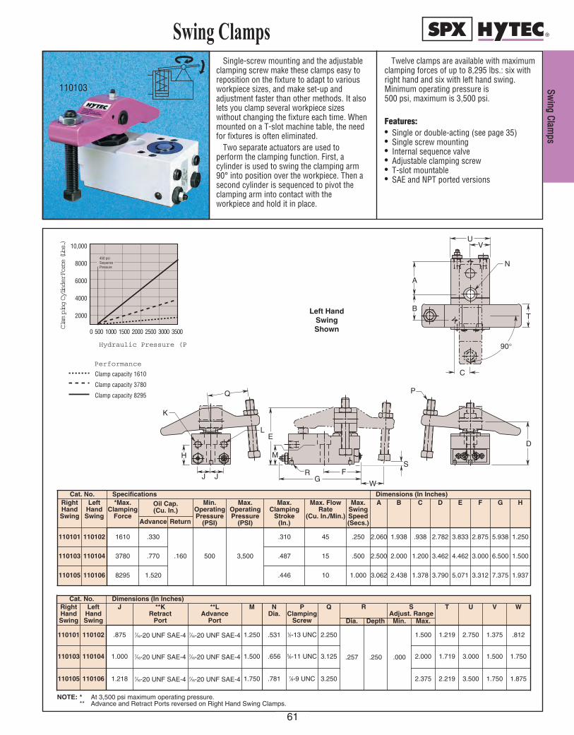
Single-screw mounting and the adjustableclamping screw make these clamps easy toreposition on the fixture to adapt to variousworkpiece sizes, and make set-up andadjustment faster than other methods. It alsolets you clamp several workpiece sizeswithout changing the fixture each time. Whenmounted on a T-slot machine table, the needfor fixtures is often eliminated.
Two separate actuators are used toperform the clamping function. First, acylinder is used to swing the clamping arm90° into position over the workpiece. Then asecond cylinder is sequenced to pivot theclamping arm into contact with theworkpiece and hold it in place.
Twelve clamps are available with maximumclamping forces of up to 8,295 lbs.: six withright hand and six with left hand swing.Minimum operating pressure is 500 psi, maximum is 3,500 psi.
Features:• Single or double-acting (see page 35)• Single screw mounting• Internal sequence valve• Adjustable clamping screw• T-slot mountable• SAE and NPT ported versions
Swing Clamps
110103
0 500 1000 1500 2000 2500 3000 3500
10,000
8000
6000
4000
2000
Hydraulic Pressure (PSI)
Clam
ping Cylinder Force (Lbs.)
450 psiSequencePressure
Performance
Clamp capacity 1610
Clamp capacity 3780
Clamp capacity 8295
Left HandSwingShown
H
J J
K
Q
LE
M
FG
RS
D
P
90°
C
TB
A
N
VU
W
Cat. No. Dimensions (In Inches)RightHandSwing
LeftHandSwing
J **KRetract
Port
**LAdvance
Port
M NDia.
PClamping
Screw
Q R SAdjust. Range
Dia. Depth Min. Max.
.875 1.250 .531 1⁄2-13 UNC 2.250
.257 .250 .000
1.500110101 110102 7⁄16-20 UNF SAE-4 7⁄16-20 UNF SAE-4
1.000 1.500 .656 5⁄8-11 UNC 3.125 2.000110103 110104 7⁄16-20 UNF SAE-4 7⁄16-20 UNF SAE-4
1.218 1.750 .781 7⁄8-9 UNC 3.250 2.375110105 110106 7⁄16-20 UNF SAE-4 7⁄16-20 UNF SAE-4 2.219
1.719
1.219
T
3.500
3.000
2.750
U
1.750
1.500
1.375
V
1.875
1.750
.812
W
Cat. No. Specifications Dimensions (In Inches)RightHandSwing
LeftHandSwing
*Max.Clamping
Force
Oil Cap. (Cu. In.)
Min.OperatingPressure
(PSI)
Max.OperatingPressure
(PSI)
Max.Clamping
Stroke (In.)
Max. FlowRate
(Cu. In./Min.)
Max.SwingSpeed(Secs.)
A B C
Advance Return
1610 .330
.160 500 3,500
.310 45 .250 1.938 .938110101 110102
3780 .770 .487 15 .500 2.500 2.000 1.200110103 110104
8295 1.520 .446 10 1.000 3.062 2.438 1.378110105 110106 3.790
3.462
2.782
D
5.071
4.462
3.833
E
3.312
3.000
2.875
F
7.375
6.500
5.938
G
1.937
1.500
1.250
H
2.060
NOTE: * At 3,500 psi maximum operating pressure.** Advance and Retract Ports reversed on Right Hand Swing Clamps.
SSwwiinngg CCllaamm
ppss
61

SSwwiinn
gg CCll
aammpp
MMoodd
iiffiiccaa
ttiioonn
IInnffoo
..
62
Swing Clamp Modification Information
• Standard arm may be customized for use in specificapplications.
• Standard clamping arm is 1045 steel heat treated to38 Rc max.
• Modified/custom-designed clamping arms must bespring biased or counterweighted so that the armpivots away from the workpiece.
• Arms must be stopped such that they do not pivotbelow the retracted height of the clamping cylinder.
NNoottee:: Modified arms may not have the sameworkpiece clamping force as standard clamps.Clamping force may be calculated by using thedimensions and cylinder force data below. Anyclamp using a modified or custom arm that is longeror heavier than the standard arm, must have its flowrestricted to prevent internal damage.
E
A
C
D
F G
H
B
CLAMPING CYLINDER
.44 2.794 .375 1.344 .864 .495 .488 1.133
1.23 3.250 .500 1.063 1.114 .742 .562 1.472
2.41 3.750 .545 .930 1.364 .866 .610 1.580
110101
110103
110105
110102
110104
110106
NOTE: * Sequence Pressure 450 psi must be subtracted from System Operating Pressure when calculating Clamping Cylinder Force. [System Operating Pressure (PSI) – 450 psi] X Effective Area (Sq. In.) = Clamping Cylinder Force (Lbs.).
.441
.629
*Clamping CylinderEffective Area (Sq. In.)
LeftHandSwing
RightHandSwing
HDia.
DDia.
A CB E GF
Specifications Dimensions (In Inches)
.566
Cat. No.
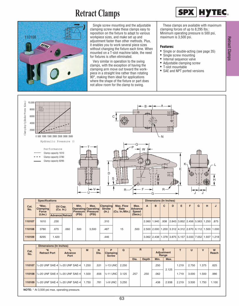
Single screw mounting and the adjustableclamping screw make these clamps easy toreposition on the fixture to adapt to variousworkpiece sizes, and make set up andadjustment faster than other methods. Plus,it enables you to work several piece sizeswithout changing the fixture each time. Whenmounted on a T-slot machine table, the needfor fixtures is often eliminated.
Very similar in operation to the swingclamps, with the exception of having theclamping arm move out toward the work-piece in a straight line rather than rotating90°, making them ideal for applicationswhere the shape of the fixture or part doesnot allow room for the clamp to swing.
These clamps are available with maximumclamping forces of up to 8,295 lbs.:Minimum operating pressure is 500 psi,maximum is 3,500 psi.
Features:• Single or double-acting (see page 35)• Single screw mounting• Internal sequence valve• Adjustable clamping screw• T-slot mountable• SAE and NPT ported versions
Retract Clamps
110108
0 500 1000 1500 2000 2500 3000 3500
10,000
8000
6000
4000
2000
Hydraulic Pressure (PSI)
Clam
ping Cylinder Force (Lbs.)
450 psiSequencePressure
Performance
Clamp capacity 1610
Clamp capacity 3780
Clamp capacity 8295
C
AB
N
J J
H
LK
RFG
M
E
W
QP
D
S
R
T
VU
Cat.No.
Specifications Dimensions (In Inches)
*Max.Clamping
Force(Lbs.)
Oil Cap. (Cu. In.)
Min.OperatingPressure
(PSI)
Max.OperatingPressure
(PSI)
ClampingStroke
(In.)
Max. FlowRate
(Cu. In./Min.)
Max.Advance
Speed(Secs.)
A B C D
Advance Retract
1610 .230
.060 500 3,500
.310
15 .500
2.060 1.940 .938 2.843110107
3780 .670 .487 2.500 2.000 1.200 3.312110108
8295 1.420 .446 3.062 2.438 1.378 3.875110109 5.157
4.312
3.852
E
3.033
2.670
2.456
F
7.052
6.112
5.563
G
1.937
1.500
1.250
H
1.218
1.000
.875
J
Cat.No.
Dimensions (In Inches)
*KRetract Port
*LAdvance
Port
M NDia.
PClamping
Screw
Q R SAdjustment
Range
T U
Dia. Depth Min. Max.
1.250 .531 1⁄2-13 UNC 2.250
.257 .250
.250
2.125
1.219 2.750110107 7⁄16-20 UNF SAE-4 7⁄16-20 UNF SAE-4
1.500 .656 5⁄8-11 UNC 3.125 .062 1.719 3.000110108 7⁄16-20 UNF SAE-4 7⁄16-20 UNF SAE-4
1.750 .781 7⁄8-9 UNC 3.250 .438 2.938 2.219 3.500110109 7⁄16-20 UNF SAE-4 7⁄16-20 UNF SAE-4 1.750
1.500
1.375
V
1.100
.986
.625
WReach
NOTE: * At 3,500 psi max. operating pressure.
RReettrraacctt CCllaamm
ppss
63

RReett
rraacctt
CCllaa
mmpp
MMoodd
iiffiiccaa
ttiioonn
IInnffoo
..
64
Retract Clamp Modification Information
• Standard arm may be customized for use inspecific applications.
• Standard clamping arm is 1045 steel heattreated to 38 Rc max.
• Modified/custom-designed clamping armsmust be spring biased or counterweightedso that the arm pivots away from theworkpiece.
NNOOTTEE:: Modified arms may not have the sameworkpiece clamping force as standardclamps. Clamping force may be calculated byusing the dimensions and cylinder force databelow. Any clamp using a modified orcustom arm that is heavier than the standardarm, must have its flow restricted to preventinternal damage.
NOTE: * Sequence Pressure 450 psi must be subtracted from System Operating Pressure when calculating Clamping Cylinder Force. [System Operating Pressure (PSI)–450 psi] X Effective Area (Sq. In.) = Clamping Cylinder Force (Lbs.).
E
C
H G
B
CLAMPING CYLINDER D
F
A
Cat.No.
Specifications Dimensions (In Inches)*Clamping Cyl.Effective Area
(Sq. In.)
A B C DMax.
EMax.
FMax.
Radius
G HDia.
.440 2.794 .375 .798 .489 .525 1.906 .439
1.230 3.250 .500 .930 1.612 .736 .587 2.250 .564110108
2.400 3.750 .545 1.055 1.893 .869 .775 2.625 .627110109
1.425110107
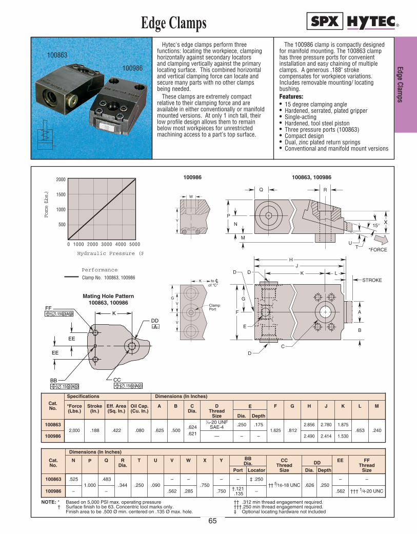
Hytec's edge clamps perform threefunctions: locating the workpiece, clamping horizontally against secondary locators and clamping vertically against the primarylocating surface. This combined horizontaland vertical clamping force can locate andsecure many parts with no other clampsbeing needed.
These clamps are extremely compactrelative to their clamping force and areavailable in either conventionally or manifoldmounted versions. At only 1 inch tall, theirlow profile design allows them to remainbelow most workpieces for unrestrictedmachining access to a part’s top surface.
The 100986 clamp is compactly designedfor manifold mounting. The 100863 clamphas three pressure ports for convenientinstallation and easy chaining of multipleclamps. A generous .188" strokecompensates for workpiece variations.Includes removable mounting/ locatingbushing.Features:• 15 degree clamping angle • Hardened, serrated, plated gripper• Single-acting• Hardened, tool steel piston• Three pressure ports (100863)• Compact design• Dual, zinc plated return springs• Conventional and manifold mount versions
Edge Clamps
0 1000 2000 3000 4000 5000
2000
1500
1000
500
Hydraulic Pressure (PSI)
Force (Lbs.)
Performance
Clamp No. 100863, 100986
Q
N
M
R
P
UT
15°
*FORCE
B
C
STROKE
K
AF
D
E
G
DDJ
L
H
X
EE
EE
BB CC
DD
K
-A-
FF .15 M A M
.15 M A M .15 M A M
K to C of "C"
V
V
G
Y
W
Clamp Port
K to C of "C"
V
V
G
Y
W
Clamp Port
100986
Mating Hole Pattern 100863, 100986
100863, 100986
100986
100863
NOTE: * Based on 5,000 PSI max. operating pressure† Surface finish to be 63. Concentric tool marks only.
Finish area to be .500 Ø min. centered on .135 Ø max. hole.
†† .312 min thread engagement required.†††.250 min thread engagement required.‡ Optional locating hardware not included
Cat. No.
Specifications Dimensions (In Inches)
*Force(Lbs.)
Stroke(In.)
Eff. Area(Sq. In.)
Oil Cap.(Cu. In.)
A B C Dia.
D Thread
Size
E F G H J K L M
1008632,000 .188 .422 .080 .625 .500
.624
.621
7⁄16-20 UNFSAE-4 .250 .175
1.625 .8122.856 2.780 1.875
.653 .240100986 – – 2.490 2.414 1.530
Cat. No.
Dimensions (In Inches)
N P Q RDia.
T U V W X Y BB Dia.
CCThread
Size
DD EE FFThread
SizePort Locator Dia. Depth
100863 .5251.000
.483.344 .250 .090
– –.750
– – ‡ .250†† 5⁄16-18 UNC .626 .250
– –
100986 – – .562 .285 .750 †.121.135 – .562 ††† 1⁄4-20 UNC
Dia. Depth
—
EEddggee CCllaammppss
65

DDiiee
CCllaa
mmpp
66
This clamp is ideal for permanentinstallation on presses to facilitate quick diechanges or can be used in many workholdingapplications. Its unique design allows it to bemounted simply by using a clamp riser equalin thickness to the member being clamped.Just two 5⁄8, grade 8 cap screws are sufficientto mount the clamp and resist its 11,180 lbs.maximum clamping force. For proper clampsupport and minimum deflection, design theriser so that it contacts the entire clampmounting surface.
Two pressure ports make these clampseasy to chain together without the need foran extra tee fitting for each clamp.
The clamp features a low overall height,heat treated body bronze plated piston and apiston rod wiper seal to keep contaminant'sout. Intended for use in 5,000 psi maximumsystems, this single acting, spring returnclamp has a .250 inch stroke.
Features:• Bronze plated piston and piston rod• Heat treated, corrosion resistant body• Rod wiper seal
Die Clamp
100839
0 1000 2000 3000 4000 5000
12,000
10,000
8000
6000
4000
2000
Hydraulic Pressure (PSI)
Force (Lbs.)
Performance
Clamp No. 100839
K
E F
G
H
J
STROKE
D
C
B A
M
L
N
P
NOTE: * Based on 5,000 psi max. operating pressure.Use of this product may require modifications of or attachments to the dies to be clamped. This work should be performed only by persons qualified to insure system safety.
Eff.Area
(Sq. In.)
SpecificationsCat. No.
Dimensions (In Inches)
*Force(Lbs.)
Stroke(In.)
Oil Cap.(Cu. In.)
.625 .625 4.00011,180100839 .250 2.236 .56 1.600 1.250 1.690 2.125 .480 .750 .050 2.190 1.095
NDia.
PPort Thread
Size
A B D J K L MF G HEDia.
C
.656 1⁄8 NPTF
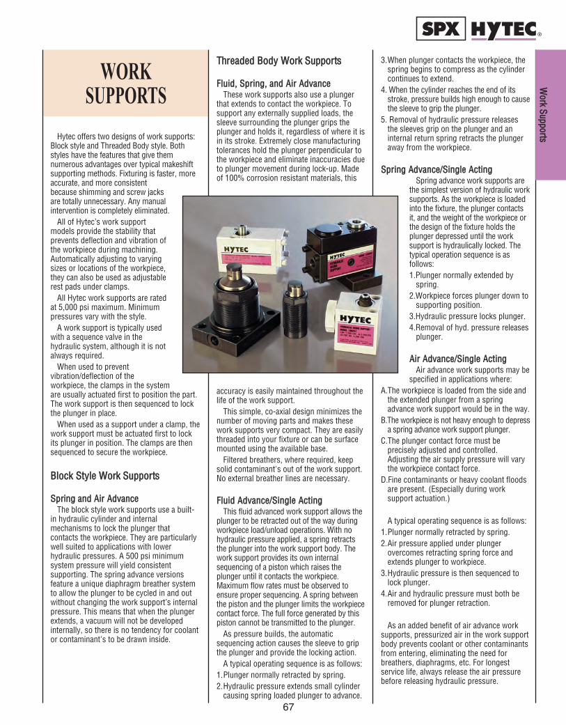
Hytec offers two designs of work supports:Block style and Threaded Body style. Bothstyles have the features that give themnumerous advantages over typical makeshiftsupporting methods. Fixturing is faster, moreaccurate, and more consistentbecause shimming and screw jacksare totally unnecessary. Any manualintervention is completely eliminated.
All of Hytec’s work supportmodels provide the stability thatprevents deflection and vibration ofthe workpiece during machining.Automatically adjusting to varyingsizes or locations of the workpiece,they can also be used as adjustablerest pads under clamps.
All Hytec work supports are ratedat 5,000 psi maximum. Minimumpressures vary with the style.
A work support is typically usedwith a sequence valve in thehydraulic system, although it is notalways required.
When used to preventvibration/deflection of theworkpiece, the clamps in the systemare usually actuated first to position the part.The work support is then sequenced to lockthe plunger in place.
When used as a support under a clamp, thework support must be actuated first to lockits plunger in position. The clamps are thensequenced to secure the workpiece.
BBlloocckk SSttyyllee WWoorrkk SSuuppppoorrttss
SSpprriinngg aanndd AAiirr AAddvvaanncceeThe block style work supports use a built-
in hydraulic cylinder and internalmechanisms to lock the plunger thatcontacts the workpiece. They are particularlywell suited to applications with lowerhydraulic pressures. A 500 psi minimumsystem pressure will yield consistentsupporting. The spring advance versionsfeature a unique diaphragm breather systemto allow the plunger to be cycled in and outwithout changing the work support’s internalpressure. This means that when the plungerextends, a vacuum will not be developedinternally, so there is no tendency for coolantor contaminant's to be drawn inside.
WORKSUPPORTS
TThhrreeaaddeedd BBooddyy WWoorrkk SSuuppppoorrttss
FFlluuiidd,, SSpprriinngg,, aanndd AAiirr AAddvvaanncceeThese work supports also use a plunger
that extends to contact the workpiece. Tosupport any externally supplied loads, thesleeve surrounding the plunger grips theplunger and holds it, regardless of where it isin its stroke. Extremely close manufacturingtolerances hold the plunger perpendicular tothe workpiece and eliminate inaccuracies dueto plunger movement during lock-up. Madeof 100% corrosion resistant materials, this
accuracy is easily maintained throughout thelife of the work support.
This simple, co-axial design minimizes thenumber of moving parts and makes thesework supports very compact. They are easilythreaded into your fixture or can be surfacemounted using the available base.
Filtered breathers, where required, keepsolid contaminant's out of the work support.No external breather lines are necessary.
FFlluuiidd AAddvvaannccee//SSiinnggllee AAccttiinnggThis fluid advanced work support allows the
plunger to be retracted out of the way duringworkpiece load/unload operations. With nohydraulic pressure applied, a spring retractsthe plunger into the work support body. Thework support provides its own internalsequencing of a piston which raises theplunger until it contacts the workpiece.Maximum flow rates must be observed toensure proper sequencing. A spring betweenthe piston and the plunger limits the workpiececontact force. The full force generated by thispiston cannot be transmitted to the plunger.
As pressure builds, the automaticsequencing action causes the sleeve to gripthe plunger and provide the locking action.
A typical operating sequence is as follows:1.Plunger normally retracted by spring.2.Hydraulic pressure extends small cylinder
causing spring loaded plunger to advance.
3.When plunger contacts the workpiece, thespring begins to compress as the cylindercontinues to extend.
4. When the cylinder reaches the end of itsstroke, pressure builds high enough to causethe sleeve to grip the plunger.
5. Removal of hydraulic pressure releasesthe sleeves grip on the plunger and aninternal return spring retracts the plungeraway from the workpiece.
SSpprriinngg AAddvvaannccee//SSiinnggllee AAccttiinnggSpring advance work supports are
the simplest version of hydraulic worksupports. As the workpiece is loadedinto the fixture, the plunger contactsit, and the weight of the workpiece orthe design of the fixture holds theplunger depressed until the worksupport is hydraulically locked. Thetypical operation sequence is asfollows:1.Plunger normally extended by
spring.2.Workpiece forces plunger down to
supporting position.3.Hydraulic pressure locks plunger.4.Removal of hyd. pressure releases
plunger.
AAiirr AAddvvaannccee//SSiinnggllee AAccttiinngg Air advance work supports may be
specified in applications where:A.The workpiece is loaded from the side and
the extended plunger from a springadvance work support would be in the way.
B.The workpiece is not heavy enough to depressa spring advance work support plunger.
C.The plunger contact force must beprecisely adjusted and controlled.Adjusting the air supply pressure will varythe workpiece contact force.
D.Fine contaminants or heavy coolant floodsare present. (Especially during work support actuation.)
A typical operating sequence is as follows:1.Plunger normally retracted by spring.2.Air pressure applied under plunger
overcomes retracting spring force andextends plunger to workpiece.
3.Hydraulic pressure is then sequenced tolock plunger.
4.Air and hydraulic pressure must both beremoved for plunger retraction.
As an added benefit of air advance worksupports, pressurized air in the work supportbody prevents coolant or other contaminantsfrom entering, eliminating the need forbreathers, diaphragms, etc. For longestservice life, always release the air pressurebefore releasing hydraulic pressure.
WWoorrkk SSuuppppoorrttss
67
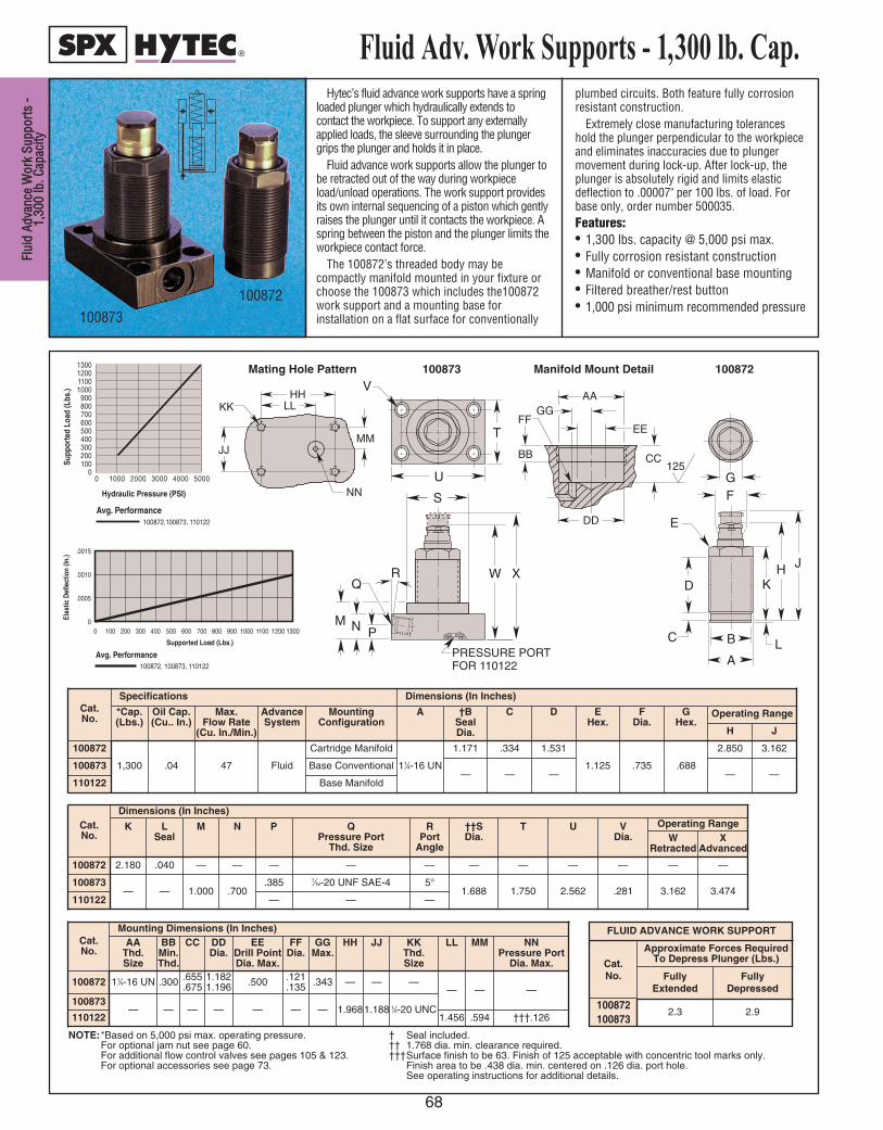
F Fl lu ui i
d d A Ad d
v va an nc c
e e W W
o or rk k
S Su up pp p
o or rt ts s
- -1 1, ,
3 30 00 0
l lb b. . C C
a ap pa ac c
i it ty y
68
Hytec’s fluid advance work supports have a springloaded plunger which hydraulically extends tocontact the workpiece. To support any externallyapplied loads, the sleeve surrounding the plungergrips the plunger and holds it in place.
Fluid advance work supports allow the plunger tobe retracted out of the way during workpieceload/unload operations. The work support providesits own internal sequencing of a piston which gentlyraises the plunger until it contacts the workpiece. Aspring between the piston and the plunger limits theworkpiece contact force.
The 100872’s threaded body may becompactly manifold mounted in your fixture orchoose the 100873 which includes the100872work support and a mounting base forinstallation on a flat surface for conventionally
plumbed circuits. Both feature fully corrosionresistant construction.
Extremely close manufacturing toleranceshold the plunger perpendicular to the workpieceand eliminates inaccuracies due to plungermovement during lock-up. After lock-up, theplunger is absolutely rigid and limits elasticdeflection to .00007" per 100 lbs. of load. Forbase only, order number 500035.Features:• 1,300 lbs. capacity @ 5,000 psi max.• Fully corrosion resistant construction• Manifold or conventional base mounting• Filtered breather/rest button• 1,000 psi minimum recommended pressure
Fluid Adv. Work Supports - 1,300 lb. Cap.
100873100872
1300120011001000
900800700600500400300200100
00 1000 2000 3000 4000 5000
Hydraulic Pressure (PSI)
Supp
orte
d Lo
ad (L
bs.)
Avg. Performance100872,100873, 110122
AA
EE
DD
BB CC 125
FF GG
MM
NN
JJ
KK LL HH
FLUID ADVANCE WORK SUPPORT
Cat. No.
100872100873
Approximate Forces Required To Depress Plunger (Lbs.)
Fully Depressed
2.3 2.9
Fully Extended
0 11001000900800700600500400300200100
.0015
.0010
.0005
0
Supported Load (Lbs.)
Elas
tic D
efle
ctio
n (In
.)
1200 1300
Avg. Performance100872, 100873, 110122
G F
E
D
C B
A L
K H J
V
T
U
Q
N P M
S
W X R
FOR 1 10122 PRESSURE POR T
Manifold Mount Detail100873Mating Hole Pattern 100872
Cat.No.
Specifications Dimensions (In Inches)
*Cap.(Lbs.)
Oil Cap.(Cu.. In.)
Max. Flow Rate
(Cu. In./Min.)
AdvanceSystem
MountingConfiguration
A †BSeal Dia.
C D EHex.
FDia.
GHex.
100872
1,300 .04 47 Fluid
Cartridge Manifold
11⁄4-16 UN
1.171 .334 1.531
1.125 .735 .688100873 Base Conventional— — —
110122 Base Manifold—
2.850
H
Operating Range
—
3.162
J
Cat.No.
Dimensions (In Inches)
K LSeal
M N P QPressure Port
Thd. Size
RPort
Angle
††SDia.
T U VDia.
Operating RangeW
Retracted
100872 2.180 .040 — — — — — — — — — —
100873— — 1.000 .700
.385 7⁄16-20 UNF SAE-4 5°1.688 1.750 2.562 .281 3.162
110122 — — —3.474
—
XAdvanced
Cat.No.
Mounting Dimensions (In Inches)AA
Thd. Size
BBMin.Thd.
CC DDDia.
EEDrill PointDia. Max.
FFDia.
GGMax.
HH JJ KKThd. Size
LL MM
100872 11⁄4-16 UN .300 .655.675
1.1821.196 .500 .121
.135 .343 — — —— —
100873— — — — — — — 1.9681.188 1⁄4-20 UNC
110122 1.456 .594 †††.126
—
NNPressure Port
Dia. Max.
NOTE:*Based on 5,000 psi max. operating pressure.For optional jam nut see page 60.For additional flow control valves see pages 105 & 123.For optional accessories see page 73.
† Seal included.†† 1.768 dia. min. clearance required.†††Surface finish to be 63. Finish of 125 acceptable with concentric tool marks only.
Finish area to be .438 dia. min. centered on .126 dia. port hole.See operating instructions for additional details.

Hytec’s fluid advance work supports have a springloaded plunger which hydraulically extends tocontact the workpiece. To support any externallyapplied loads, the sleeve surrounding the plungergrips the plunger and holds it in place.
Fluid advance work supports allow the plungerto be retracted out of the way during workpieceload/unload operations. The work support providesits own internal sequencing of a piston whichgently raises the plunger until it contacts theworkpiece. A spring between the piston and theplunger limits the workpiece contact force.
The 100882’s threaded body may be compactlymanifold mounted in your fixture or choose theNo. 100883 which includes the 100882 worksupport and a mounting base for installation on aflat surface for conventionally plumbed circuits.
Both feature fully corrosion resistant construction.Extremely close manufacturing tolerances hold
the plunger perpendicular to the workpiece andeliminate inaccuracies due to plunger movementduring lock-up. After lock-up, the plunger isabsolutely rigid and limits elastic deflection to.00004" per 100 lbs. of load. For base only, ordernumber 500028 for conventional mounting, and421728 for manifold mounting.Features:• 4,000 lbs. capacity @ 5,000 psi max.• Fully corrosion resistant construction• Manifold mount or conventional base mounting• Small, filtered breather/rest button to
accommodate intricate workpieces• 1,000 psi minimum recommended pressure
Fluid Adv. Work Supports-4,000 lb. Cap.
Manifold Mount Detail
Mating Hole Pattern
100882
100883
FLUID ADVANCE WORK SUPPORT
Cat. No.
100882100883
Approximate Forces Required To Depress Plunger (Lbs.)
Fully Depressed
4 8
Fully Extended
100883
100882
PP
RR
LL
MM NN KK
AA
EE
DD
BB CC 125
FF
GG
JJ
HH
G F
H J
K
L B A
E
D
C
W X
T
V
M N P
R
Q
U
S
FOR 110123PRESSURE PORT
40003600320028002400200016001200
800400
00 1000 2000 3000 4000 5000
Hydraulic Pressure (PSI)
Supp
orte
d Lo
ad (L
bs.)
Avg. Performance100882, 100883, 110123
0 40003600320028002400200016001200800400
.0020
.0015
.0010
.0005
0
Supported Load (Lbs.)
Elas
tic D
efle
ctio
n (In
.)
Avg. Performance100882, 100883, 110123
Cat.No.
Specifications Dimensions (In Inches)
*Cap.(Lbs.)
Oil Cap.(Cu. In.)
Max. FlowRate
(Cu. In./Min.)
AdvanceSystem
MountingConfiguration
A †BSealDia.
C D EHex.
FDia.
GHex
100882
4,000 .12 10 Fluid
Cartridge Manifold
21⁄4-16 UN
2.140 .250 1.625
2.000 .735 .688100883 Base Conventional— — —
110123 Base Manifold—
3.265
H
Operating Range
—
3.765
J
—
2.312
K
Cat.No.
Dimensions (In Inches)
LSeal
M N P QPress. Port Thd.
Size
RPort
Angle
††SDia.
T U V Operating rangeW
RetractedX
Advanced
100882 .040 — — — — — — — — — — —
100883— .945 .735
.420 7⁄16-20 UNF SAE-4 5°2.688 2.750 3.562 .281 3.680 4.180
110123 — — —
Cat.No.
Mounting Dimensions (In Inches)AA
Thd. Size
BBMin.Thd.
CC DDDia.
EEDril Point
Max.
FF GGDia.
HHDia.
JJMax.
KK LL MMThd. Size
100882 21⁄4-16 UN .380 .560.580
2.1822.196 .500 .080
.1002.1452.155
.121
.293 .700 — — —
100883— — — — — — — — — 2.843 2.063 1⁄4-20 UNC
110123 2.122
—
NN
1.032
—
PP
†††.126
—
RRPressure Port
Dia. Max.
NOTE: * Based on 5,000 psi max. operating pressureFor optional jam nut see page 60For additional flow control valves see pgs. 105 & 123.For optional accessories see page 73.
† Seal included.†† 2.768 dia. min. clearance required.
††† Surface finish to be 63. Finish of 125 acceptablewith concentric tool marks only. Finish area to be.438 dia. min. centered on .126 dia. port hole. Seeoperating instructions for additional port details.
F Fl lu ui id d A Ad dv va an nc ce e W Wo or rk k S Su up pp po or rt ts s - -
4 4, ,0 00 00 0 l lb b. . C Ca ap pa ac ci it ty y
69

S Sp pr ri in n
g g A Ad d
v va an nc c
e e W W
o or rk k
S Su up pp p
o or rt ts s
- -1 1, ,
3 30 00 0
l lb b. . C C
a ap pa ac c
i it ty y
70
Spring Adv. Work Supports-1,300 lb. Cap.
100874
100875
1300120011001000
900800700600500400300200100
00 1000 2000 3000 4000 5000
Hydraulic Pressure (PSI)
Supp
orte
d Lo
ad (L
bs.)
Avg. Performance100874,100875,110124
AA
EE
DD
BB CC 125
FF GG
MM
NN
JJ
KK LL HH
V
T
U
Q
N P M
S
W X R
FOR 1 10124 PRESSURE POR T
G F
E
D
C B
A L
K H J
NOTE: *Based on 5,000 psi max. operating pressure.**Per ISO 6149-1
For optional jam nut see page 60.For additional flow control valves see pages 105 & 123.
For optional accessories see page 73.† Seal included.†† 1.768 dia. min. clearance required.
††† Surface finish to be 63. Finish of 125 acceptable withconcentric tool marks only.
Finish area to be .438 dia. min. centered on .126 dia. port hole.See operating instructions for additional details.
100875Mating Hole Pattern 100874
Manifold Mount Detail
0 11001000900800700600500400300200100
.0015
.0010
.0005
0
Supported Load (Lbs.)
Elas
tic D
efle
ctio
n (In
.)
1200 1300
Avg. Performance100874,100875, 110124
SPRING ADVANCE WORK SUPPORT
Cat. No.
100874100875110134110124
Approximate Forces Required To Depress Plunger (Lbs.)
Fully Depressed
2.3 2.9
Fully Extended
Cat.No.
Mounting Dimensions (In Inches)
AAThd. Size
BBMin.Thd.
CC DDDia.
EEDrill Port
Max.
FFDia.
GGMax.
HH JJ KKThd. Size
LL MM
100874 11⁄4-16 UN .300 .655.675
1.1821.196 .500 .121
.135 .343 — — —
— —100875
— — — — — — — 1.9681.188 1⁄4-20 UNC110134
1.456 .594 .126
—
†††NNPressure Port
Dia. Max.
110124
110134
Cat.No.
Specifications Dimensions (In Inches)
*Cap.(Lbs.)
Oil Cap.(Cu. In.)
AdvanceSystem
MountingConfiguration
A †BSeal Dia.
C D EHex.
FDia.
GHex.
100874
1,300 .01 Spring
Cartridge Manifold
11⁄4-16 UN
1.171 .334 1.531
1.125 .735 .688100875
Base Conventional— — —
Base Manifold
—
2.850
H
Operating Range
—
3.162
J
110124
—
Cat.No.
Dimensions (In Inches)
K LSeal
M N P QPressure Port
Thd. Size
RPort
Angle
††SDia.
T U VDia.
Operating RangeW
Retracted
100874 2.180 .040 — — — — — — — — — —
100875
— — 1.000 .700.385
7⁄16-20 UNF SAE-45°
1.688 1.750 2.562 .281 3.162
110124 —
**M12 x 1.5 6H
—
3.474
—
XAdvanced
110134
Hytec’s spring advance work supports have aspring loaded plunger which contacts theworkpiece as it is loaded into the fixture. Thespring keeps the plunger in contact with theworkpiece, allowing for variations betweenworkpieces. To support any externally suppliedloads, the sleeve surrounding the poppet gripsthe plunger and holds it in place.
The 100874 and 110124’s threaded body maybe compactly manifold mounted in your fixtureor choose the 100875 or metric version 110134which includes the 100874 work support and amounting base for installation on a flat surfacefor conventionally plumbed circuits. Both featurefully corrosion resistant construction.
Extremely close manufacturing tolerances holdthe plunger perpendicular to the workpiece andeliminates inaccuracies due to plunger movementduring lock-up. After lock-up, the plunger isabsolutely rigid and limits elastic deflection to.00007" per 100 lbs. of load. For base only, ordernumber 500035 for conventional mounting, and421727 for manifold mounting.Features:• 1,300 lbs. capacity @ 5,000 psi max.• Fully corrosion resistant construction• Manifold mount or conventional base
mounting• Filtered breather/rest button• 1,000 psi minimum recommended pressure
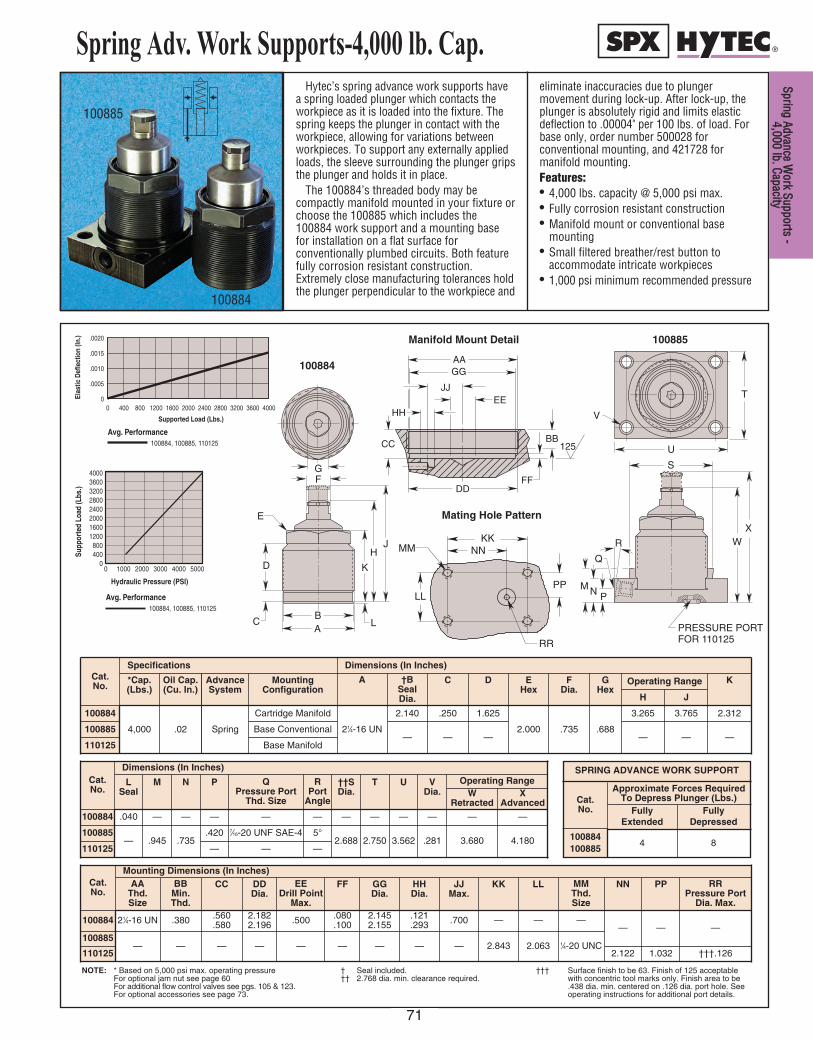
Spring Adv. Work Supports-4,000 lb. Cap.
Manifold Mount Detail
Mating Hole Pattern
100884
100885
100885
100884
PP
RR
LL
MM NN KK
AA
EE
DD
BB CC 125
FF
GG
JJ
HH
G F
H J
K
L B A
E
D
C
W X
T
V
M N P
R
Q
U
S
FOR 110125PRESSURE PORT
40003600320028002400200016001200
800400
00 1000 2000 3000 4000 5000
Hydraulic Pressure (PSI)
Supp
orte
d Lo
ad (L
bs.)
Avg. Performance100884, 100885, 110125
0 40003600320028002400200016001200800400
.0020
.0015
.0010
.0005
0
Supported Load (Lbs.)
E l a s
t i c D
e f l e
c t i o
n ( I n
. )
Avg. Performance100884, 100885, 110125
NOTE: * Based on 5,000 psi max. operating pressureFor optional jam nut see page 60For additional flow control valves see pgs. 105 & 123.For optional accessories see page 73.
† Seal included.†† 2.768 dia. min. clearance required.
††† Surface finish to be 63. Finish of 125 acceptablewith concentric tool marks only. Finish area to be.438 dia. min. centered on .126 dia. port hole. Seeoperating instructions for additional port details.
Cat.No.
Specifications Dimensions (In Inches)
*Cap.(Lbs.)
Oil Cap.(Cu. In.)
AdvanceSystem
MountingConfiguration
A †BSealDia.
C D EHex
FDia.
GHex
100884
4,000 .02 Spring
Cartridge Manifold
21⁄4-16 UN
2.140 .250 1.625
2.000 .735 .688100885 Base Conventional— — —
110125 Base Manifold—
3.265
H
Operating Range
—
3.765
J
—
2.312
K
Cat.No.
Dimensions (In Inches)
LSeal
M N P QPressure Port
Thd. Size
RPort
Angle
††SDia.
T U VDia.
Operating RangeW
RetractedX
Advanced
100884 .040 — — — — — — — — — — —
100885— .945 .735
.420 7⁄16-20 UNF SAE-4 5°2.688 2.750 3.562 .281 3.680 4.180
110125 — — —
Cat.No.
Mounting Dimensions (In Inches)AA
Thd. Size
BBMin.Thd.
CC DDDia.
EEDrill Point
Max.
FF GGDia.
HHDia.
JJMax.
KK LL MMThd. Size
100884 21⁄4-16 UN .380 .560.580
2.1822.196 .500 .080
.1002.1452.155
.121
.293 .700 — — —
100885— — — — — — — — — 2.843 2.063 1⁄4-20 UNC
110125 2.122
—
NN
1.032
—
PP
†††.126
—
RRPressure Port
Dia. Max.
SPRING ADVANCE WORK SUPPORT
Cat. No.
100884100885
Approximate Forces Required To Depress Plunger (Lbs.)
Fully Depressed
4 8
Fully Extended
Hytec’s spring advance work supports havea spring loaded plunger which contacts theworkpiece as it is loaded into the fixture. Thespring keeps the plunger in contact with theworkpiece, allowing for variations betweenworkpieces. To support any externally appliedloads, the sleeve surrounding the plunger gripsthe plunger and holds it in place.
The 100884’s threaded body may be compactly manifold mounted in your fixture orchoose the 100885 which includes the100884 work support and a mounting basefor installation on a flat surface forconventionally plumbed circuits. Both featurefully corrosion resistant construction.Extremely close manufacturing tolerances holdthe plunger perpendicular to the workpiece and
eliminate inaccuracies due to plungermovement during lock-up. After lock-up, theplunger is absolutely rigid and limits elasticdeflection to .00004" per 100 lbs. of load. Forbase only, order number 500028 forconventional mounting, and 421728 formanifold mounting.Features:• 4,000 lbs. capacity @ 5,000 psi max.• Fully corrosion resistant construction• Manifold mount or conventional base
mounting• Small filtered breather/rest button to
accommodate intricate workpieces• 1,000 psi minimum recommended pressure
SSpprri in ng g A Ad dv va an nc ce e W Wo or rk k S Su up pp po or rt ts s - -
4 4, ,0 00 00 0 l lb b. . C Ca ap pa ac ci it ty y
71
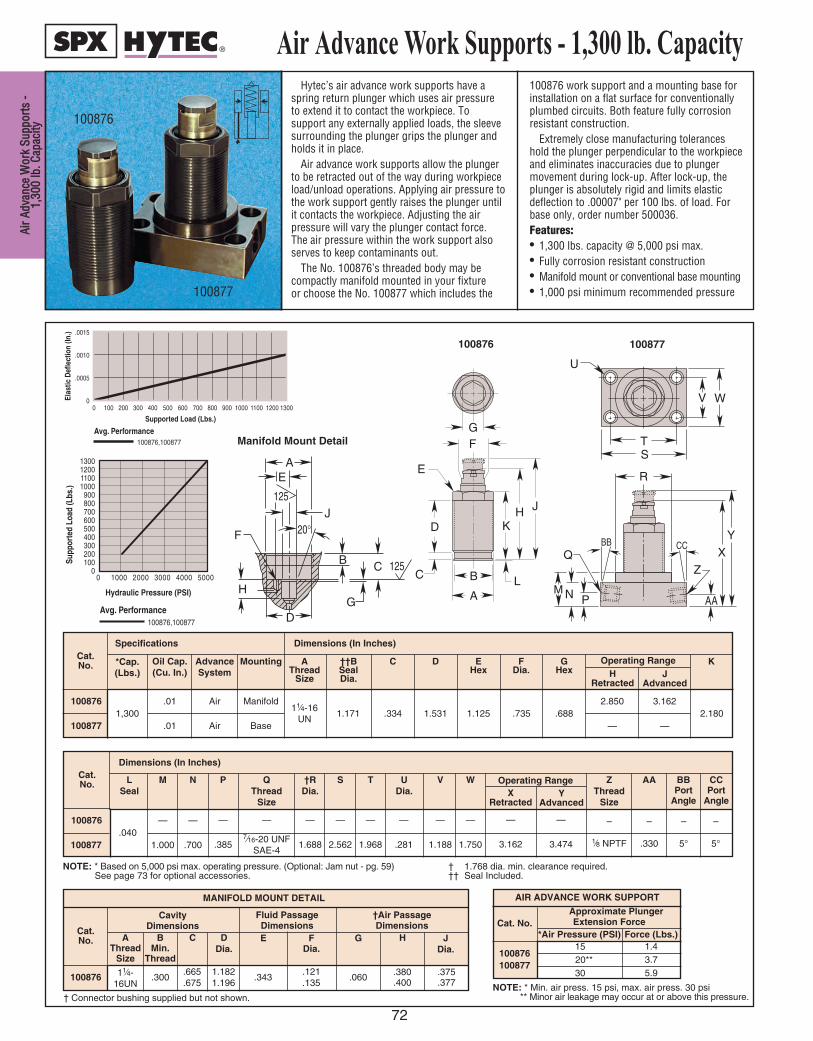
A Ai ir r A A
d dv va an n
c ce e W W
o or rk k
S Su up pp p
o or rt ts s
- - 1 1, ,
3 30 00 0
l lb b. . C C
a ap pa ac c
i it ty y
72
Hytec’s air advance work supports have aspring return plunger which uses air pressureto extend it to contact the workpiece. Tosupport any externally applied loads, the sleevesurrounding the plunger grips the plunger andholds it in place.
Air advance work supports allow the plungerto be retracted out of the way during workpieceload/unload operations. Applying air pressure tothe work support gently raises the plunger untilit contacts the workpiece. Adjusting the airpressure will vary the plunger contact force. The air pressure within the work support alsoserves to keep contaminants out.
The No. 100876’s threaded body may becompactly manifold mounted in your fixture or choose the No. 100877 which includes the
100876 work support and a mounting base forinstallation on a flat surface for conventionallyplumbed circuits. Both feature fully corrosionresistant construction.
Extremely close manufacturing toleranceshold the plunger perpendicular to the workpieceand eliminates inaccuracies due to plungermovement during lock-up. After lock-up, theplunger is absolutely rigid and limits elasticdeflection to .00007" per 100 lbs. of load. Forbase only, order number 500036.Features:• 1,300 lbs. capacity @ 5,000 psi max.• Fully corrosion resistant construction• Manifold mount or conventional base mounting• 1,000 psi minimum recommended pressure
Air Advance Work Supports - 1,300 lb. Capacity
100876
100877
Cat. No.
100876
Cavity Dimensions
Fluid Passage Dimensions
MANIFOLD MOUNT DETAIL
BMin.
Thread
11⁄4-16UN
.300.665.675
AThread
Size
C
1.1821.196
DDia.
.343
E
.121
.135
FDia.
G
.060
H
.375
.377.380.400
JDia.
Cat. No.
100876
100877
.01
.01
Specifications Dimensions (In Inches)
*Cap.(Lbs.)
Oil Cap.(Cu. In.)
Air
Air
AdvanceSystem
Manifold
Base
Mounting
1,30011⁄4-16
UN
AThread
Size
1.171
††BSealDia.
.334
C
1.531
D
1.125
EHex
.735
FDia.
.688
GHex
2.180
KOperating Range
2.850
—
HRetracted
3.162
—
JAdvanced
Cat. No.
100876
100877
—
1.000
Dimensions (In Inches)
LSeal
ZThread
Size
AA
–
1⁄8 NPTF
–
.330
BBPort
Angle
–
5°
CCPort
Angle
–
5°
M
—
.700
N
—
.385
P
—
1.688
†RDia.
—
2.562
S
—
1.188
V
—
1.750
W
—
1.968
T
—
7⁄16-20 UNFSAE-4
QThread
Size
—
.281
UDia.
.040
Operating Range
—
3.162
XRetracted
—
3.474
YAdvanced
AIR ADVANCE WORK SUPPORT
Cat. No.
100876100877
Approximate Plunger Extension Force
Force (Lbs.)1520**30
1.43.75.9
*Air Pressure (PSI)
NOTE: * Based on 5,000 psi max. operating pressure. (Optional: Jam nut - pg. 59)See page 73 for optional accessories.
† 1.768 dia. min. clearance required.†† Seal Included.
† Connector bushing supplied but not shown.NOTE: * Min. air press. 15 psi, max. air press. 30 psi
** Minor air leakage may occur at or above this pressure.
†Air PassageDimensions
Avg. Performance100876,100877
0 11001000900800700600500400300200100
.0015
.0010
.0005
0
Supported Load (Lbs.)
Elas
tic D
efle
ctio
n (In
.)
1200 1300
1300120011001000
900800700600500400300200100
00 1000 2000 3000 4000 5000
Hydraulic Pressure (PSI)
Supp
orte
d Lo
ad (L
bs.)
Avg. Performance100876,100877 D
H
F
G
B C 125
J20°
EA
125
U
V W
T S
R
Z
X Q
AA N P M
Y BB CC
G F
E
D
C B
A L
K H J
Manifold Mount Detail
100876 100877

100872, 100874
Work Support Accessories
E
D C
B A
G
F
RReesstt BBuuttttoonnThis Rest Button is designed to extend the reach of all Hytec threaded
body work supports. All of Hytec’s fluid-advanced and air-advancedthreaded body work supports must be able to “breathe” air for properoperation. Proper filtration as it breathes is also critical for maximumservice life. This button contains the same filtered breather port as thestandard rest button. It is easily modified above the hex to fit your exactrequirements. Its tapered design minimizes weight and off-center loading.• Fits 1,300 and 4,000 lb, Work Supports• Built-in filter element• Provides 1.375”additional reach beyond standard button• Easily modified for your application
Additional end effectors will add weight and may affect performance. Ifneither the standard nor the optional 500176 rest buttons are appropriatefor your application, contact Hytec for more design information.
CCoooollaanntt DDeefflleeccttoorr CCaappssThese Coolant Deflector Caps are designed to reduced exposure of the
work support’s breather/filter to coolant and contaminants. They aredesigned for applications where the work support is actuated either duringor soon after exposure to coolant floods. Used in conjunction with carefulaiming of coolant jets, they can prevent the breather port from filling withcoolant that is later drawn inside the work support as it is actuated.
The caps are assembled between the work support plunger and the restbutton and serve as an “umbrella” for the breather port. (This increasesthe height of the assembled work support by .030”)
The caps are designed for vertical-up and horizontal applications wherecoolant jets are not directly aimed at the gap between the cap and worksupport plunger.
These caps are not appropriate for submerged or vertical-down applications.
Cat.No.
Dimensions (In Inches)
A B CDia.
DDia.
E FThd. Size
GHex
500176 1.500 .250 .562 1.875 1⁄2-20 UNF .688
A
B
B
A
DEFLECT OR CAP (500178)
DEFLECT OR CAP (500179)
FFeeeeddeerr CCaappssThese Feeder Caps are designed to
allow bulkhead mounting Hytec’sfluid advanced and spring advancedthreaded body work supports.Bulkhead mounting allows the worksupport to be mounted in a threadedhole in a plate. The feeder capconnects the work support to thehydraulic system via a SAE-4 port.The feeder cap saves space over thestandard base and provides aconnection at the end of the worksupport. The work support should belocked to the bulkhead plate using ajam nut or by the feeder cap itself.
500181
500180
C
D
E
B
D
E
A
C
B A
FEEDER CAP
Cat.No.
Dimensions (In Inches)
A B
500178 1.435 .635
500179 1.410 1.060
4,000 lbs.
1,300 lbs.
500176
Cat.No.
Work SupportCap. (Lbs.)
Use With
500180 1,300
500181 4,000 100882, 100884
Cat.No.
Dimensions (In Inches)
A B CHex
D E
500180 11⁄4-16 1.750 1.125 .460
500181 21⁄4-16 2.750 1.010
.376
500176 1.500 .250 .562 1.875 1⁄2-20 UNF .688.376
Work Support
Capacity
7⁄16-20 UNF SAE-4.435
WWoorrkk SSuuppppoorrtt AAcccceessssoorriieess
73
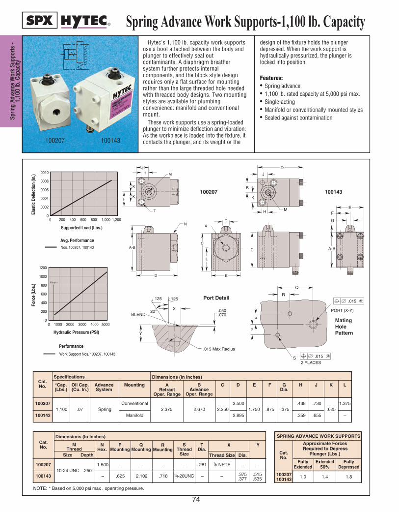
S Sp pr ri in n
g g A Ad d
v va an nc c
e e W W
o or rk k
S Su up pp p
o or rt ts s
- -1 1, ,
1 10 00 0
l lb b. . C C
a ap pa ac c
i it ty y
74
Hytec's 1,100 lb. capacity work supportsuse a boot attached between the body andplunger to effectively seal outcontaminants. A diaphragm breathersystem further protects internalcomponents, and the block style designrequires only a flat surface for mountingrather than the large threaded hole neededwith threaded body designs. Two mountingstyles are available for plumbingconvenience: manifold and conventionalmount.
These work supports use a spring-loadedplunger to minimize deflection and vibration:As the workpiece is loaded into the fixture, itcontacts the plunger, and its weight or the
design of the fixture holds the plungerdepressed. When the work support ishydraulically pressurized, the plunger islocked into position.
Features:• Spring advance• 1,100 lb. rated capacity at 5,000 psi max.• Single-acting• Manifold or conventionally mounted styles• Sealed against contamination
Spring Advance Work Supports-1,100 lb. Capacity
100207 100143
K
K
H M
J
D
C
G
EF
A-B
K
F
JH M
T
A-B
D
N
E
C
L
GX
K
Y
125 125
X 20 °
BLEND .050 .070
.015 Max Radius
P
P
Q
R
PORT (X-Y)
.015 M
.015 M S 2 PLACES
0
.0010
.0008
.0006
.0004
.0002
0
Supported Load (Lbs.)
Elas
tic D
efle
ctio
n (In
.)
Avg. PerformanceNos. 100207, 100143
200 400 600 800 1,000 1,200
0 1000 2000 3000 4000 5000
1200
1000
800
600
400
200
0
Hydraulic Pressure (PSI)
Forc
e (L
bs.)
Performance
Work Support Nos. 100207, 100143
500 p.s.i.
100207
Port Detail
MatingHolePattern
100143
10020710-24 UNC .250
1.500 – – – – .281 1⁄8 NPTF – –
100143 – .625 2.102 .718 1⁄4-20UNC – –
NOTE: * Based on 5,000 psi max . operating pressure.
ARetract
Oper. Range
BAdvance
Oper. Range
Specifications Dimensions (In Inches)
MountingAdvanceSystem
Oil Cap.(Cu. In.)
*Cap.(Lbs.)
H JFEDC GDia.
K LCat. No.
1002071,100 .07 Spring
Conventional2.375 2.670 2.250
2.5001.750 .875 .375
.438 .730.625
1.375
100143 Manifold 2.895 .359 .655 –
Dimensions (In Inches)
M Thread
Cat. No. N
Hex.T
Dia.P
MountingQ
MountingR
MountingS
ThreadSizeSize Thread Size
YX
Depth Dia.
.375
.377.515.535
SPRING ADVANCE WORK SUPPORTS
Approximate Forces Required to Depress
Plunger (Lbs.)
Fully Extended FullyExtended 50% Depressed
100207100143 1.0 1.4 1.8
Cat.No.
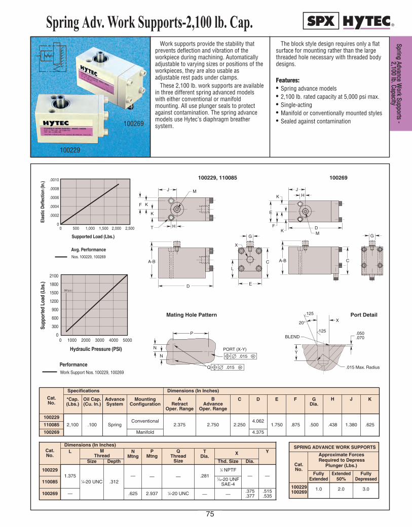
Work supports provide the stability thatprevents deflection and vibration of theworkpiece during machining. Automaticallyadjustable to varying sizes or positions of theworkpieces, they are also usable asadjustable rest pads under clamps.
These 2,100 lb. work supports are availablein three different spring advanced modelswith either conventional or manifoldmounting. All use plunger seals to protectagainst contamination. The spring advancemodels use Hytec’s diaphragm breathersystem.
The block style design requires only a flatsurface for mounting rather than the largethreaded hole necessary with threaded bodydesigns.
Features:• Spring advance models• 2,100 lb. rated capacity at 5,000 psi max.• Single-acting• Manifold or conventionally mounted styles• Sealed against contamination
Spring Adv. Work Supports-2,100 lb. Cap.
100229
100269
Mating Hole Pattern
100269100229, 110085
Port Detail
SPRING ADVANCE WORK SUPPORTS
Approximate Forces Required to Depress
Plunger (Lbs.)
Fully Extended FullyExtended 50% Depressed
100229 1.0 2.0 3.0100269
0
.0010
.0008
.0006
.0004
.0002
0
Supported Load (Lbs.)
Elas
tic D
efle
ctio
n (In
.)
Avg. PerformanceNos. 100229, 100269
500 1,000 1,500 2,000 2,500 H
K
K
F
J
T
A-B C
G
M
D E
L
X
D
K
K F
E
J H
M
A-B C
G
20 °
125
125
Y
.050
.070
.015 Max. Radius
BLEND
X
N
N
P
Q
.015 M
.015 M
PORT (X-Y)
Supp
orte
d Lo
ad (L
bs.)
2100
1800
1500
1200
900
600
300
0
Hydraulic Pressure (PSI)
Performance
0 1000 2000 3000 4000 5000
Work Support Nos. 100229, 100269
500 p.s.i.
Cat.No.
Cat.No.
Specifications Dimensions (In Inches)
*Cap.(Lbs.)
Oil Cap.(Cu. In.)
AdvanceSystem
MountingConfiguration
ARetract
Oper. Range
BAdvance
Oper. Range
C D E F GDia.
100229
2,100 .100 SpringConventional
2.375 2.750 2.2504.062
1.750 .875 .500110085
100269 Manifold
.438
H
1.380 .625
KJ
4.375
Cat.No.
Dimensions (In Inches)L M
ThreadN
MtngP
MtngQ
Thread Size
TDia.
X Y
1002291.375
1⁄4-20 UNC .312— — — .281
1⁄4 NPTF— —
1100857⁄16-20 UNF
SAE-4
100269 .625 2.937 1⁄4-20 UNC
Size Depth Thd. Size Dia.
— — —.375.377
.515
.535
S Sp pr ri in ng g A Ad dv va an nc ce e W Wo or rk k S Su up pp po or rt ts s - -
2 2, ,1 10 00 0 l lb b. . C Ca ap pa ac ci it ty y
75
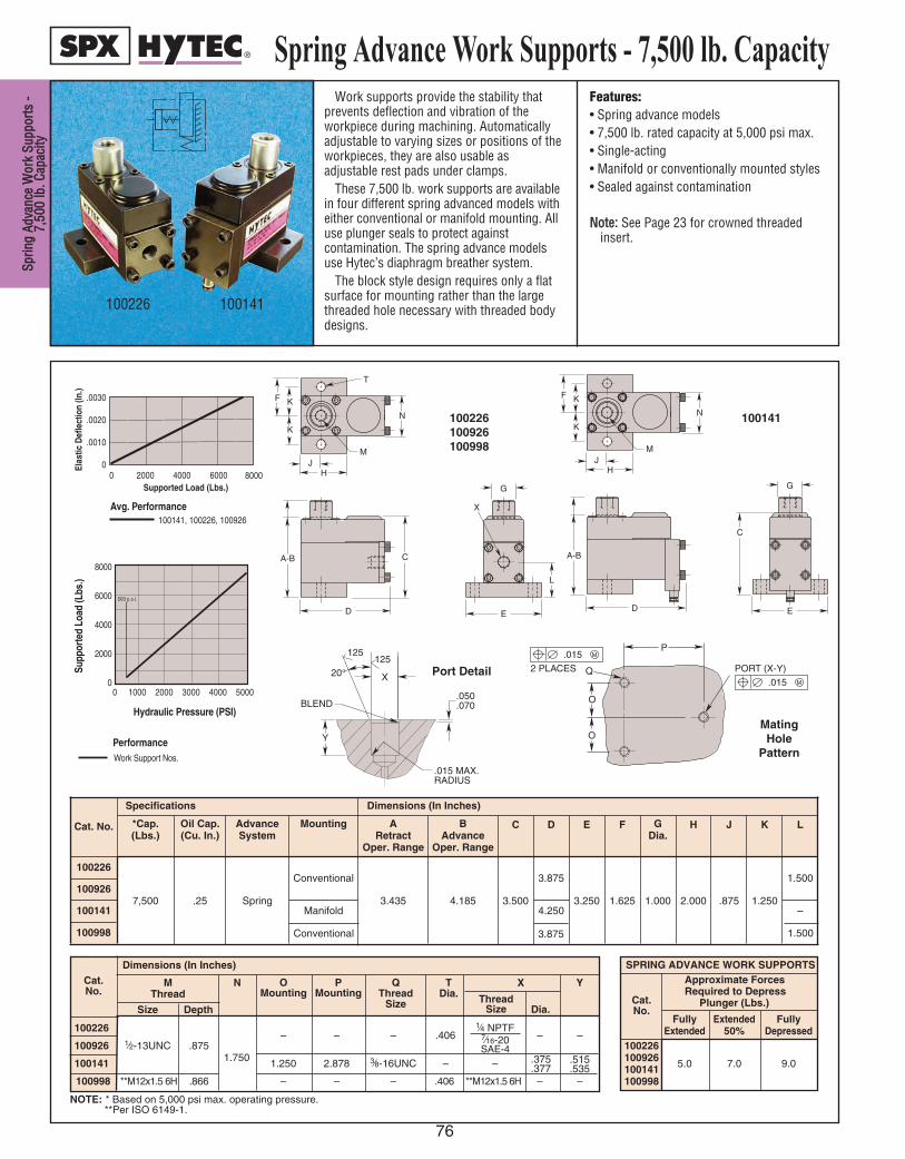
S Sp pr ri in n
g g A Ad d
v va an nc c
e e W W
o or rk k
S Su up pp p
o or rt ts s
- -7 7, ,
5 50 00 0
l lb b. . C C
a ap pa ac c
i it ty y
76
Spring Advance Work Supports - 7,500 lb. Capacity
SPRING ADVANCE WORK SUPPORTSApproximate Forces Required to Depress
Plunger (Lbs.)
Fully Extended FullyExtended 50% Depressed
100226100926 5.0 7.0 9.0100141100998
Cat.No.
Work supports provide the stability thatprevents deflection and vibration of theworkpiece during machining. Automaticallyadjustable to varying sizes or positions of theworkpieces, they are also usable asadjustable rest pads under clamps.
These 7,500 lb. work supports are availablein four different spring advanced models witheither conventional or manifold mounting. Alluse plunger seals to protect againstcontamination. The spring advance modelsuse Hytec’s diaphragm breather system.
The block style design requires only a flatsurface for mounting rather than the largethreaded hole necessary with threaded bodydesigns.
Features:• Spring advance models• 7,500 lb. rated capacity at 5,000 psi max.• Single-acting• Manifold or conventionally mounted styles• Sealed against contamination
NNoottee:: See Page 23 for crowned threadedinsert.
0 2000
.0030
.0020
.0010
0
Supported Load (Lbs.)
Elas
tic D
efle
ctio
n (In
.)
A vg. P erf ormance 100141, 100226, 100926
4000 6000 8000
Supp
orte
d Lo
ad (L
bs.)
Hydraulic Pressure (PSI)
Performance
0 1000 2000 3000 4000 5000
8000
6000
4000
2000
0
Work Support Nos.
100226, 100141, 100926
500 p.s.i.
20 °
125 125
Y
.050
.070
.015 MAX. RADIUS
BLEND
X .015 M
.015 M
PORT (X-Y)
O
O
Q 2 PLACES
P
F K
K
JH
M
N
A-B
D
C
G
E
F K
K
J H
M
N
A-B
D
G
E
C
X
L
T
100226 100141
NOTE: * Based on 5,000 psi max. operating pressure.**Per ISO 6149-1.
XM Thread
Dimensions (In Inches)Cat. No.
Size Depth
QThread
Size
PMounting
OMounting
N
Thread Size
YTDia.
Dia.
.515
.535.375 .377
7⁄16-20SAE-4
MatingHole
Pattern
100141
Port Detail
100226100926100998
100998
Cat. No.
Specifications Dimensions (In Inches)
*Cap.(Lbs.)
Oil Cap.(Cu. In.)
AdvanceSystem
Mounting ARetract
Oper. Range
BAdvance
Oper. Range
C D E F GDia.
H J K L
100226
7,500 .25 Spring
Conventional
3.435 4.185 3.500
3.875
3.250 1.625 1.000 2.000 .875 1.250
1.500100926
100141 Manifold 4.250 –
Conventional 3.875 1.500
100226– – – .406
1⁄4 NPTF– –
100926 1⁄2-13UNC .8751.750100141 1.250 2.878 3⁄8-16UNC – –
100998 **M12x1.5 6H .866 – – – .406 **M12x1.5 6H – –

Work supports provide the stability thatprevents deflection and vibration of theworkpiece during machining. Automaticallyadjustable to varying sizes or positions of theworkpieces, they are also usable asadjustable rest pads under clamps.
These 2,100 lb. air advanced worksupports are available in three differentmodels with either conventional or manifoldmounting. All use plunger seals to protectagainst contamination.
The block style design requires only a flatsurface for mounting rather than the largethreaded hole necessary with threadedbody designs.
Features:• Air advance• 2,100 lb. rated capacity at 5,000 psi max.• Single-acting• Manifold or conventionally mounted styles• Sealed against contamination
Air Adv. Work Supports - 2,100 lb. Cap.
100177
100176
NOTE: * Based on 5,000 psi max. operating pressure. NOTE: * Min. air pressure 25 psi,max. air pressure 50 psi.
Supp
orte
d Lo
ad (L
bs.)
0 1000 2000 3000 4000 5000
2100
1800
1500
1200
900
600
300
0
Hydraulic Pressure (PSI)
PerformanceWork Support Nos. 100176, 100177
500 p.s.i.
J
H
E
L
G
C
D
N
B A
H
F
K
K
M
Q
P
R
0
.0010
.0008
.0006
.0004
.0002
0
Supported Load (Lbs.)
Elas
tic D
efle
ctio
n (In
.)
Avg. PerformanceNos. 100176, 100177
500 1,000 1,500 2,000 2,500
Y
T
S
SEEPORTDETAIL
W
V
U
U
.015 M 20 °
125
125
Z
.050
.070
.015 Max. Radius
BLEND
Y
R
C
E
G
D
H H
F K
K
B A
AIR INLET
M
100176,110086
100177
Port DetailMating Hole Pattern
AIR ADVANCE WORK SUPPORTS
Cat.No.
Approximate PlungerExtension Force
*Air Press.(PSI)
Force (Lbs.)
100176100177110086
30 2.2
40 4.5
50 7.1
Cat.No.
Specifications Dimensions (In Inches)*Cap.(Lbs.)
Oil Cap.
(Cu. In.)
AdvanceSystem
MountingConfiguration
ARetract
Oper. Range
BAdvance
Oper. Range
C D E F GDia.
H
100176
2,100 .100 AirConventional
2.250 2.625 2.2503.542
1.750 .875 .500 .438110086
100177 Manifold 3.862
.875
J
.625
K
—
1.375
L
Cat.No.
Dimensions (In Inches) Mounting Dimensions (In Inches)
M Thread N PAir Inlet
Port
QPort
RDia.
S T U VThread
Size
WDia. Air
Inlet
X
Size Depth
1001761⁄4-20UNC .312
.685 1⁄8 NPTF
1⁄4 NPTF
.281— — — — — —
1100867⁄16-20 UNF
SAE-4
100177 — — — 2.937 .876 .6251⁄4-20UNC .125 .515
.535.375.377
—
YDia.
Mtng.
A Ai ir r A Ad dv va an nc ce e W Wo or rk k S Su up pp po or rt ts s - -
2 2, ,1 10 00 0 l lb b. . C Ca ap pa ac ci it ty y
77

A Ai ir r A A
d dv va an n
c ce e W W
o or rk k
S Su up pp p
o or rt ts s
- - 7 7, ,
5 50 00 0
l lb b. . C C
a ap pa ac c
i it ty y
78
Air Adv. Work Supports - 7,500 lb. Cap.Similar in operation to our other air
advance work supports, Hytec’s 7,500 lb.work supports‘ unique interlocking pindesign gives more holding capacity thanother units of similar size.
The block style design requires only a flatsurface for mounting rather than the largethreaded hole necessary with threaded bodydesigns.
Air advance work supports may bespecified in applications whenever theworkpiece is loaded from the side and theextended plunger from a spring advancework support would be in the way, or theworkpiece is not heavy enough to depress aspring advance work support plunger, or theplunger contact force must be precisely
adjusted and controlled. Adjusting the airsupply pressure will vary the workpiececontact force.
Features:• Air advance• 7,500 lb. rated capacity at 5,000 psi max.• Single-acting• Sealed against contamination• Convenient dual air inlets allow easy
connection and chaining of work supportsNNoottee:: See page 23 for crowned threaded
insert. See page 124 for air inlet adapterfitting.
100847100844
NOTE: * Based on 5,000 psi max. operating pressure. **Per ISO 1179. ***Per ISO 6149-1.
AIR ADVANCE WORK SUPPORTS
Approximate PlungerExtension Force*Air Force
Pressure (PSI) (Lbs.)
NOTE: * Min. air pressure 25 psi, max. airpressure 100 psi.
0 2000
.0030
.0020
.0010
0
Supported Load (Lbs.)
Elas
tic D
efle
ctio
n (In
.)
Avg. PerformanceNos. 100844, 100847
4000 6000 8000
F K
K
Q
N
J H
M
A-B
D O
L
C
P
E
L
R
G S
F K
K
Q
N
J H
M
A-B
D O
L
C
P
E
L
R
G S
100844, 110087, 110136 100847, 110088, 110135
0 2000
.0030
.0020
.0010
0
Supported Load (Lbs.)
Elas
tic D
efle
ctio
n (In
.)
Avg. PerformanceNos. 100844, 100847
4000 6000 8000
Cat.No.
Cat.No.
Dimensions (In Inches)
M Thread N O PAir Inlet
Port
QDia.
RPort
SFlats
Size Depth
100844
1⁄2-13 UNC .625
1.750 .830
1⁄16 NPTF
.406
1⁄4 NPTF
.875
110087 7⁄16-20 UNF SAE-4
100847 1⁄4 NPTF
110088 7⁄16-20 UNF SAE-4
100844100847110087110088110135110136
110135
Cat.No.
Specifications Dimensions (In Inches)
*Cap.(Lbs.)
Oil Cap.(Cu. In.)
AdvanceSystem
MountingConfiguration
ARetract
Oper. Range
BAdvance
Oper. Range
C D E F GDia.
H
100844
7,500 .250 Air Conventional
3.435 4.185 3.500
3.875 3.250 1.625 1.000 2.000
110087
100847
4.435 5.615 4.227110088.875
J
1.250
K
2.000
1.500
L
110136 3.435 4.115 3.500 1.500
110135
110136
***M12x1.5 6H .580 **G 1/8-28 ***M12x1.5 6H
30 8.0
70 33.0
100 49.0

79
POWER SOURCES
EELLEECCTTRRIICC//HHYYDDRRAAUULLIICC
HHYYDDRRAAUULLIICC IINNTTEENNSSIIFFIIEERR
AAIIRR//HHYYDDRRAAUULLIICC
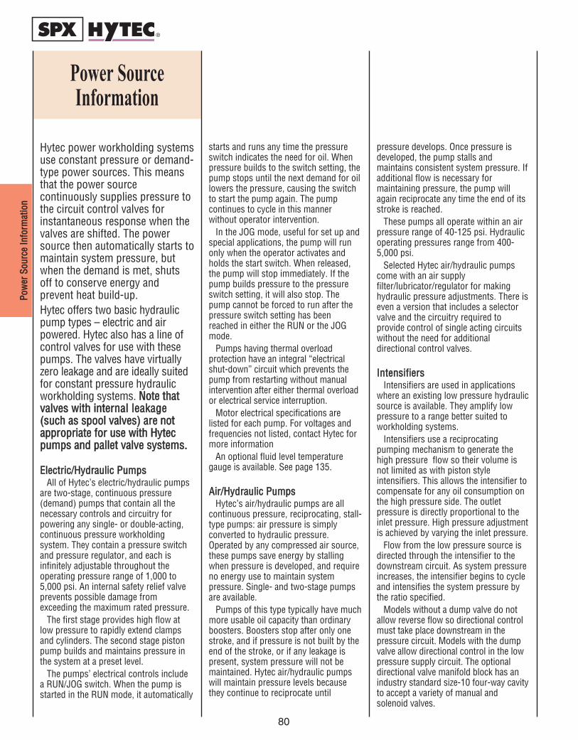
PPooww
eerr SS
oouurrcc
ee IInn
ffoorrmm
aattiioo
nn
80
Power SourceInformation
starts and runs any time the pressureswitch indicates the need for oil. Whenpressure builds to the switch setting, thepump stops until the next demand for oillowers the pressure, causing the switchto start the pump again. The pumpcontinues to cycle in this mannerwithout operator intervention.
In the JOG mode, useful for set up andspecial applications, the pump will runonly when the operator activates andholds the start switch. When released,the pump will stop immediately. If thepump builds pressure to the pressureswitch setting, it will also stop. Thepump cannot be forced to run after thepressure switch setting has beenreached in either the RUN or the JOGmode.
Pumps having thermal overloadprotection have an integral “electricalshut-down” circuit which prevents thepump from restarting without manualintervention after either thermal overloador electrical service interruption.
Motor electrical specifications arelisted for each pump. For voltages andfrequencies not listed, contact Hytec formore information
An optional fluid level temperaturegauge is available. See page 135.
AAiirr//HHyyddrraauulliicc PPuummppssHytec’s air/hydraulic pumps are all
continuous pressure, reciprocating, stall-type pumps: air pressure is simplyconverted to hydraulic pressure.Operated by any compressed air source,these pumps save energy by stallingwhen pressure is developed, and requireno energy use to maintain systempressure. Single- and two-stage pumpsare available.
Pumps of this type typically have muchmore usable oil capacity than ordinaryboosters. Boosters stop after only onestroke, and if pressure is not built by theend of the stroke, or if any leakage ispresent, system pressure will not bemaintained. Hytec air/hydraulic pumpswill maintain pressure levels becausethey continue to reciprocate until
pressure develops. Once pressure isdeveloped, the pump stalls andmaintains consistent system pressure. Ifadditional flow is necessary formaintaining pressure, the pump willagain reciprocate any time the end of itsstroke is reached.
These pumps all operate within an airpressure range of 40-125 psi. Hydraulicoperating pressures range from 400-5,000 psi.
Selected Hytec air/hydraulic pumpscome with an air supplyfilter/lubricator/regulator for makinghydraulic pressure adjustments. There iseven a version that includes a selectorvalve and the circuitry required toprovide control of single acting circuitswithout the need for additionaldirectional control valves.
IInntteennssiiffiieerrssIntensifiers are used in applications
where an existing low pressure hydraulicsource is available. They amplify lowpressure to a range better suited toworkholding systems.
Intensifiers use a reciprocatingpumping mechanism to generate thehigh pressure flow so their volume isnot limited as with piston styleintensifiers. This allows the intensifier tocompensate for any oil consumption onthe high pressure side. The outletpressure is directly proportional to theinlet pressure. High pressure adjustmentis achieved by varying the inlet pressure.
Flow from the low pressure source isdirected through the intensifier to thedownstream circuit. As system pressureincreases, the intensifier begins to cycleand intensifies the system pressure bythe ratio specified.
Models without a dump valve do notallow reverse flow so directional controlmust take place downstream in thepressure circuit. Models with the dumpvalve allow directional control in the lowpressure supply circuit. The optionaldirectional valve manifold block has anindustry standard size-10 four-way cavityto accept a variety of manual andsolenoid valves.
Hytec power workholding systemsuse constant pressure or demand-type power sources. This meansthat the power sourcecontinuously supplies pressure tothe circuit control valves forinstantaneous response when thevalves are shifted. The powersource then automatically starts tomaintain system pressure, butwhen the demand is met, shutsoff to conserve energy andprevent heat build-up.Hytec offers two basic hydraulicpump types – electric and airpowered. Hytec also has a line ofcontrol valves for use with thesepumps. The valves have virtuallyzero leakage and are ideally suitedfor constant pressure hydraulicworkholding systems. NNoottee tthhaattvvaallvveess wwiitthh iinntteerrnnaall lleeaakkaaggee((ssuucchh aass ssppooooll vvaallvveess)) aarree nnoottaapppprroopprriiaattee ffoorr uussee wwiitthh HHyytteeccppuummppss aanndd ppaalllleett vvaallvvee ssyysstteemmss..
EElleeccttrriicc//HHyyddrraauulliicc PPuummppssAll of Hytec’s electric/hydraulic pumps
are two-stage, continuous pressure(demand) pumps that contain all thenecessary controls and circuitry forpowering any single- or double-acting,continuous pressure workholdingsystem. They contain a pressure switchand pressure regulator, and each isinfinitely adjustable throughout theoperating pressure range of 1,000 to5,000 psi. An internal safety relief valveprevents possible damage fromexceeding the maximum rated pressure.
The first stage provides high flow atlow pressure to rapidly extend clampsand cylinders. The second stage pistonpump builds and maintains pressure inthe system at a preset level.
The pumps’ electrical controls includea RUN/JOG switch. When the pump isstarted in the RUN mode, it automatically

Electric/Hydraulic Pum
ps
This two-stage, continuous pressure(demand) pump contains all thenecessary controls and circuitry forpowering single- or double-actingcontinuous pressure workholdingsystems. It has a pressure switch andpressure regulator, both infinitelyadjustable throughout the operatingpressure range of 1,000 to 5,000 psi. Aninternal safety relief valve preventsdamage from exceeding the maximumrated pressure. It's an economicalgerotor/radial piston pump designed forremote mounted valves only. Consult
Hytec for information on pump mountedvalves. Shipped with 1.5 gallons of oil.FFeeaattuurreess::• Drip proof induction motor• CSA approved• Filtered filler/breather cap• Liquid filled gauge• Carrying handle• Thermal overload protection• 2-gallon, high density polyethylene
reservoir• 1⁄4" NPTF outlet manifold• 33 cu. in./min. oil flow at max. pressure• 295 cu. in. usable oil
81
Electric/Hydraulic Pumps
0 250 500 1000 2000 3000 4000 5000
300
250
200
150
100
50
Hydraulic Pressure (PSI)
Oil V olume (Cu. In./Min.)
Performance
No. 100178
D
C
G
F
B
E A
H
M
Power Sources
81

Elec
tric
/Hyd
raul
ic P
umps
82
This electric/hydraulic pump is a two-stage,continuous pressure (demand) pump thatcontains all the necessary controls and circuitryfor powering any single- or double-actingcontinuous pressure workholding system. It hasa pressure switch and an external pressureregulator, both infinitely adjustable throughoutthe operating pressure range of 1,000 to 5,000psi. An internal safety relief valve preventsdamage from exceeding the maximum ratedpressure.
It's a gear/axial piston pump designed foruse in single or multiple station applications.Its high torque universal motor is low voltage
tolerant. Includes a 1⁄4" NPTF outlet manifoldand will accept any Hytec pump-mountedvalve. Shipped with two gallons of oil. FFeeaattuurreess::• CSA approved model available• Drip proof universal motor• Filtered filler/breather cap• Liquid filled gauge• Carrying handle• 2.5-gallon metal reservoir• 525 cu. in. usable oil• Oil flow at max. pressure: 100 cu.
in./min.
Electric/Hydraulic Pumps
Performance
No. 100220
500 1000 2000 3000 4000 5000
800
700
600
500
400
300
200
100
0
Hydraulic Pressure (PSI)
Oil Volume (Cu. In./Min.)
E B
D
G
A
F C
H
100220
M
NOTE: An optional fluid level / temperature gauge is available, see page 135.
Specifications Dimensions (In Inches)
Cat. No.
ElectricMotor
SupplyVoltage
Noise Level@ Idle/Max. Press.
(dBA)
A B C D E F GThread
Size
H
100220
11⁄8 hp; 12,000 rpm;115 VAC;
25 amps max.;50/60 Hz; single phase
115 VAC
80/85 18.250 12.500 10.500 7.000 10.000 8.000 1⁄2-20 UNF 14.000
100220-230
11⁄8 hp; 12,000 rpm;230 VAC;
14 amps max.;50/60 Hz; single phase
230 VAC
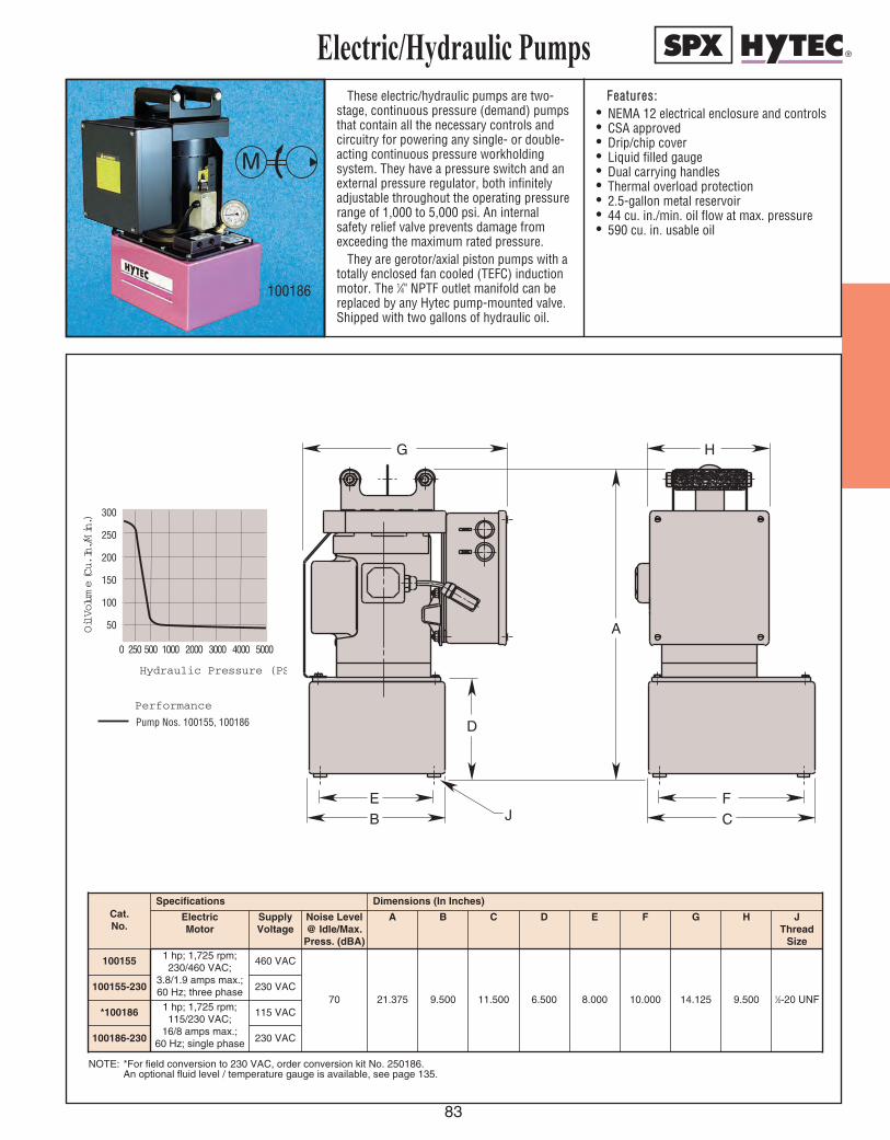
Electric/Hydraulic Pum
ps
These electric/hydraulic pumps are two-stage, continuous pressure (demand) pumpsthat contain all the necessary controls andcircuitry for powering any single- or double-acting continuous pressure workholding system. They have a pressure switch and anexternal pressure regulator, both infinitelyadjustable throughout the operating pressurerange of 1,000 to 5,000 psi. An internalsafety relief valve prevents damage fromexceeding the maximum rated pressure.
They are gerotor/axial piston pumps with atotally enclosed fan cooled (TEFC) inductionmotor. The 1⁄4" NPTF outlet manifold can bereplaced by any Hytec pump-mounted valve.Shipped with two gallons of hydraulic oil.
FFeeaattuurreess::• NEMA 12 electrical enclosure and controls • CSA approved• Drip/chip cover• Liquid filled gauge• Dual carrying handles• Thermal overload protection• 2.5-gallon metal reservoir• 44 cu. in./min. oil flow at max. pressure• 590 cu. in. usable oil
83
Electric/Hydraulic PumpsOil Volume (Cu. In./Min.)
0 250 500 1000 2000 3000 4000 5000
300
250
200
150
100
50
Hydraulic Pressure (PSI)
Performance
Pump Nos. 100155, 100186
NOTE: *For field conversion to 230 VAC, order conversion kit No. 250186.An optional fluid level / temperature gauge is available, see page 135.
E B
D
J
A
F C
H G
100186
M
Specifications Dimensions (In Inches)Cat. No.
Electric Motor
SupplyVoltage
Noise Level@ Idle/Max.Press. (dBA)
A B C D E F G H
100155 1 hp; 1,725 rpm;230/460 VAC;
3.8/1.9 amps max.;60 Hz; three phase
460 VAC
70 21.375 9.500 11.500 6.500 8.000 10.000 14.125 9.500100155-230 230 VAC
JThread
Size
1⁄2-20 UNF*100186 1 hp; 1,725 rpm;
115/230 VAC;16/8 amps max.;
60 Hz; single phase
115 VAC
100186-230 230 VAC

Elec
tric
Hyd
raul
ic P
umps
84
Electric/Hydraulic PumpsThese electric/hydraulic pumps are two-
stage, continuous pressure (demand) pumpsthat contain all the necessary controls andcircuitry for powering any single- or double-acting continuous pressure workholding system. They contain a pressure switch andpressure regulator that are infinitelyadjustable throughout the operating pressurerange of 1,000 to 5,000 psi.
They are gerotor/axial piston pumps, idealfor use in single or multiple stationapplications, and include a 1⁄4" NPTF outletmanifold and will accept any Hytec pump-mounted valve. Shipped with four gallons ofoil.
FFeeaattuurreess::• Enclosed induction motor• Filtered filler/breather cap• Liquid filled gauge• Carrying handles• Thermal overload protection• 5.7-gallon metal reservoir• Oil flow at max. press.: 125 cu. in./min.• 1,250 cu. in. usable oil• External pressure regulator• Pressure switch
NOTE: † CSA Approved.
M
100211
Specifications Dimensions (In Inches)
Cat. No.
ElectricMotor
SupplyVoltage
Noise Level@ Idle/Max. Press.
(dBA)
A B C D E F GThread
Size
100211†
2 hp; 1,725 rpm;115/230 VAC;
27/14 amps max.;50/60 Hz; single phase
115/23074/76 25.125 14.250 15.500 7.250 12.125 13.312 1⁄2-20 UNFVAC

Hydraulic Intensifiers
Intensifiers are used in applications where anexisting low pressure hydraulic source is available.They amplify low pressure to a range better suitedto workholding systems
Intensifiers use a reciprocating pumpingmechanism to generate the high pressure flow sotheir volume is not limited as with piston styleintensifiers. This allows the intensifier tocompensate for any oil consumption on the highpressure side. The outlet pressure is directlyproportional to the inlet pressure. High pressureadjustment is achieved by varying the inletpressure.
Flow from the low pressure source is directedthrough the intensifier to the downstream circuit.As system pressure increases, the intensifierbegins to cycle and intensifies the system
pressure by the ratio specified.Models without a dump valve do not allow
reverse flow so directional control must take placedownstream in the high pressure circuit. Modelswith the dump valve allow directional control inthe low pressure supply circuit. The optionaldirectional valve manifold block has a standardVickers C-10-4 cavity to accept a variety of manualand solenoid valves. Fitting No. 253288 can beused with part No. 100997. See page 126 forspecs.FFeeaattuurreess::
• 5,000 psi max.• 3.2, 4 and 5.1 ratios available• Optional valve manifold• Extremely compact size
85
Hydraulic Intensifiers
100991
100997
M
N
L P
R
S
T
U
V
100991
100997
Specifications Dimensions (In Inches)Cat No. Pressure
IntensificationRatio
Inlet Flow Max.
(Cu. in./min.)
Outlet Flow Max.
(Cu. in./min.)
Inlet Pressure A B CDia.
DFlats
EThread
SizeWith DumpValve
W/O DumpValve
Min. (psi) Max. (psi)
100991 100994 3.2 to 1 610 150
300
1,560
4.331 3.583 1.968 1.606 M24 x 1.5
100993 100996 5.0 to 1 550 95 1,000
100992 100995 4.0 to 1 580 120 1,250
FOutletThread
Size
9⁄16-18 UNFSAE-6
Dimensions (In Inches)Cat No. G H J
ReturnThread
SizeWith Dump
ValveW/O Dump
Valve
100991 100994
.551 1.1027⁄16-20 UNF
SAE-4100993 100996
100992 100995
KInlet
ThreadSize
7⁄16-20 UNFSAE-4
Cat No.
Dimensions (In Inches)L M N P R S T U
ReturnThread
Size
100997 2.441 3.543 1.968 1.968 .984 1.256 1.260 1⁄4 BSPP
VInlet
ThreadSize
1⁄4 BSPP
NOTE: Approximate inlet to outlet leakage is 1 cu. in./min. Requires 10 micron nominalfiltration. Hytec filter 100919 is ideal for protecting the inlet port. M24-1.5 nut included.
IMPORTANT: Demands created by the addition of this device to an existing hydraulic system can cause fluctuations in available pressureand flow to that system. The effects of these fluctuations on the original system must be evaluated by the designer of that system.
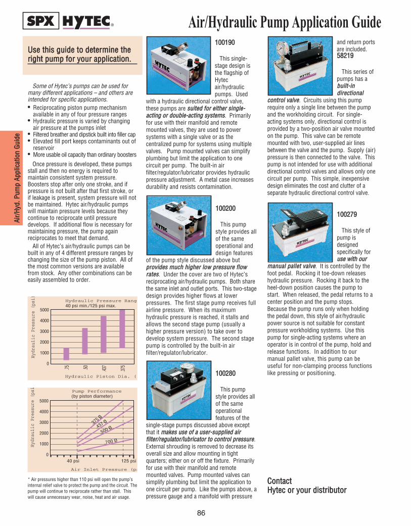
UUssee tthhiiss gguuiiddee ttoo ddeetteerrmmiinnee tthheerriigghhtt ppuummpp ffoorr yyoouurr aapppplliiccaattiioonn..
5000
4000
3000
2000
1000
0
.75 .50 .437
.375
Hydraulic Piston Dia. (in.)
Hydr
auli
c Pr
essu
re (
psi) Hydraulic Pressure Range
40 psi min./125 psi max.
110000119900
This single-stage design isthe flagship ofHytecair/hydraulicpumps. Used
with a hydraulic directional control valve,these pumps are ssuuiitteedd ffoorr eeiitthheerr ssiinnggllee--aaccttiinngg oorr ddoouubbllee--aaccttiinngg ssyysstteemmss. Primarilyfor use with their manifold and remotemounted valves, they are used to powersystems with a single valve or as thecentralized pump for systems using multiplevalves. Pump mounted valves can simplifyplumbing but limit the application to onecircuit per pump. The built-in airfilter/regulator/lubricator provides hydraulicpressure adjustment. A metal case increasesdurability and resists contamination.
110000220000
This pumpstyle provides allof the sameoperational anddesign features
of the pump style discussed above butpprroovviiddeess mmuucchh hhiigghheerr llooww pprreessssuurree fflloowwrraatteess. Under the cover are two of Hytec’sreciprocating air/hydraulic pumps. Both sharethe same inlet and outlet ports. This two-stagedesign provides higher flows at lowerpressures. The first stage pump receives fullairline pressure. When its maximumhydraulic pressure is reached, it stalls andallows the second stage pump (usually ahigher pressure version) to take over todevelop system pressure. The second stagepump is controlled by the built-in airfilter/regulator/lubricator.
110000228800
This pumpstyle provides allof the sameoperationalfeatures of the
single-stage pumps discussed above exceptthat it mmaakkeess uussee ooff aa uusseerr--ssuupppplliieedd aaiirrffiilltteerr//rreegguullaattoorr//lluubbrriiccaattoorr ttoo ccoonnttrrooll pprreessssuurree.External shrouding is removed to decrease itsoverall size and allow mounting in tightquarters; either on or off the fixture. Primarilyfor use with their manifold and remotemounted valves. Pump mounted valves cansimplify plumbing but limit the application toone circuit per pump. Like the pumps above, apressure gauge and a manifold with pressure
Air/Hydraulic Pump Application Guide
Some of Hytec’s pumps can be used formany different applications – and others areintended for specific applications.• Reciprocating piston pump mechanism
available in any of four pressure ranges• Hydraulic pressure is varied by changing
air pressure at the pumps inlet• Filtered breather and dipstick built into filler cap• Elevated fill port keeps contaminants out of
reservoir• More usable oil capacity than ordinary boosters
Once pressure is developed, these pumpsstall and then no energy is required tomaintain consistent system pressure.Boosters stop after only one stroke, and ifpressure is not built after that first stroke, orif leakage is present, system pressure will notbe maintained. Hytec air/hydraulic pumpswill maintain pressure levels because theycontinue to reciprocate until pressuredevelops. If additional flow is necessary formaintaining pressure, the pump againreciprocates to meet that demand.
All of Hytec’s air/hydraulic pumps can bebuilt in any of 4 different pressure ranges bychanging the size of the pump piston. All ofthe most common versions are availablefrom stock. Any other combinations can beeasily assembled to order.
* Air pressures higher than 110 psi will open the pump’sinternal relief valve to protect the pump and the circuit. Thepump will continue to reciprocate rather than stall. Thiswill cause unnecessary wear, noise, heat and air usage.
Air Inlet Pressure (psi)
Hydr
auli
c Pr
essu
re (
psi)
Pump Performance (by piston diameter)
and return portsare included.5588221199
This series ofpumps has abbuuiilltt--iinnddiirreeccttiioonnaall
ccoonnttrrooll vvaallvvee. Circuits using this pumprequire only a single line between the pumpand the workholding circuit. For single-acting systems only, directional control isprovided by a two-position air valve mountedon the pump. This valve can be remotemounted with two, user-supplied air linesbetween the valve and the pump. Supply (air)pressure is then connected to the valve. Thispump is not intended for use with additionaldirectional control valves and allows only onecircuit per pump. This simple, inexpensivedesign eliminates the cost and clutter of aseparate hydraulic directional control valve.
110000227799
This style ofpump isdesignedspecifically foruussee wwiitthh oouurr
mmaannuuaall ppaalllleett vvaallvvee. It is controlled by thefoot pedal. Rocking it toe-down releaseshydraulic pressure. Rocking it back to theheel-down position causes the pump tostart. When released, the pedal returns to acenter position and the pump stops.Because the pump runs only when holdingthe pedal down, this style of air/hydraulicpower source is not suitable for constantpressure workholding systems. Use thispump for single-acting systems where anoperator is in control of the pump, hold andrelease functions. In addition to ourmanual pallet valve, this pump can beuseful for non-clamping process functionslike pressing or positioning.
CCoonnttaacctt HHyytteecc oorr yyoouurr ddiissttrriibbuuttoorr
AAiirr//
HHyydd
.. PPuumm
pp AApp
pplliicc
aattiioo
nn GG
uuiiddee
86

Air/Hydraulic Pum
ps
87
Available with all piston options, thissingle-stage pump is a continuous pressure,reciprocating, stall-type pump: air pressureis simply converted to hydraulic pressure.Operated by any compressed air source, thispump saves energy by stalling whenpressure is developed, and requires noenergy to maintain system pressure. Itfeatures single-stage operation, and canaccept any Hytec pump-mounted valve. Anair supply filter/lubricator/ regulator (notincluded) is required for making hydraulicpressure adjustments.
FFeeaattuurreess::• Filtered fill cap with dipstick• Liquid filled gauge• 105 cu. in., high-density polyethylene
reservoir• 1⁄4" NPTF outlet manifold• 1⁄4" NPTF air inlet port• 98 cu. in. usable oil• Shipped filled with oil• Operating Pressure Range (nominal):
110000228800-- 4,475 psi @ 125 psi air, max.1,150 psi @ 40 psi air, min..437 dia. piston size
110000998877-- 3,325 psi @ 125 psi air, max.925 psi @ 40 psi air, min..50 dia. piston size
Air/Hydraulic Pumps
No. 10028040 psi Air Pressure125 psi Air Pressure
1000 2000 3000 4000 5000
200
150
100
50
0
Hydraulic Pressure (PSI)
Oil Volume (Cu. In./Min.)
Performance
C
F
A
B D E
100280
No. 10028040 psi Air Pressure125 psi Air Pressure
1000 2000 3000 4000 5000
200
150
100
50
0
Hydraulic Pressure (PSI)
Oil Volume (Cu. In./Min.)
Performance
1000 2000 3000 4000
300
200
100
0
Hydraulic Pressure (PSI)
Oil Vo l u m e ( C u . I n . / M i n . )
Performance
No. 10098740 psi Air Pressure125 psi Air Pressure
Cat.No.
Specifications Dimensions (In Inches)
Piston Dia.
Operating PressureRange A B D E F
Ports@ 125 psiAir Max.
@ 40 psi Air Min.
100280 .437 4,475 1,1507.000 10.000 5.000 9.000 4.000 1⁄4 NPT
100987 .500 3,325 925
C
NOTE: Mounting screws included (9-15 x 1.000 Lg.).AIR REQUIREMENTS: 20 CFM (max.) at low hydraulic pressure decreasing to 0 CFM when pump stalls.

Air/
Hyd
raul
ic P
umps
Air/Hydraulic PumpsAvailable with all piston options, this
single-stage power source is a continuouspressure, reciprocating, stall-type pump. Airpressure is simply converted to usablehydraulic pressure. Operated by anycompressed air source, this pump savesenergy by stalling when hydraulic pressure isdeveloped and then requires no additionalenergy to maintain system pressure.
Designed for single acting systems, thispump has a built-in selector valve to chooseeither the pressurize or release mode. Noadditional valving is required. An air supplyfilter/regulator/lubricator (not included) isrequired for making pressure adjustments.
FFeeaattuurreess::• Filtered fill cap with dipstick• Liquid filled gauge• 105 in3., high-density polyethylene reservoir• 1⁄4" NPTF outlet port• 1⁄8" NPTF air inlet port• 98 cu. in. usable oil• Shipped filled with oil• Carrying handle for easy portability• Operating Pressure Range (nominal):
110000992211-- 5,000 psi @ 110 psi air, max.1,500 psi @ 40 psi air, min., .375 dia. piston size5588221199-- 4,475 psi @ 125 psi air, max.1,150 psi @ 40 psi air, min., .437 dia. piston size110000991188-- 3,325 psi @ 125 psi air, max.925 psi @ 40 psi air, min., .50 dia. piston size
No. 5821940 psi Air Pressure125 psi Air Pressure
1000 2000 3000 4000 5000
200
150
100
50
0
Hydraulic Pressure (PSI)
Oil Vo l u m e ( C u . I n . / M i n . )
Performance
1000 2000 3000 4000
300
200
100
0
Hydraulic Pressure (PSI)
Oil Volume (Cu. In./Min.)
Performance
No. 10091840 psi Air Pressure125 psi Air Pressure
No. 10092140 psi Air Pressure110 psi Air Pressure
1000 2000 3000 4000 5000
150
100
50
0
Hydraulic Pressure (PSI)
Oil Volume (Cu. In./Min.)
Performance
C
A
D
B
E
F
NOTE: Mounting screws included (9-15 x 1.000 Lg.).AIR REQUIREMENTS: 20 CFM (max.) at low hydraulic pressure decreasing to 0 CFM when pump stalls.
58219
Cat.No.
Specifications Dimensions (In Inches)
58219 .437
Piston Dia.
Operating Pressure Range A B C D E
4,475
FAir Inlet
Port
1,150
@ 125 psi Air Max.
@ 40 psi Air Min.
100921 .375 5,000 1,500
9.032 10.000 5.000 9.000 4.000 1⁄8 NPT
100918 .500 3,325 925
88

Air/Hydraulic Pum
ps
These single-stage pumps are continuouspressure, reciprocating, stall-type pumps: Airpressure is simply converted to hydraulicpressure. Operated by any compressed airsource, these pumps save energy by stallingwhen pressure is developed, and require noenergy use to maintain system pressure. Theywill accept any Hytec pump-mounted valve.
FFeeaattuurreess::• 105 cu. in., high-density polyethylene
reservoir• Filtered fill cap with dipstick• Liquid filled gauge• 1⁄4" NPTF outlet manifold
• 1⁄4" NPTF air inlet port• 98 cu. in usable oil• Shipped filled with oil• Operating Pressure Range (nominal):
110000992200 – 5,000 psi @ 110 psi air, max.1,500 psi @ 40 psi air, min..375 dia. piston size110000119900 – 4,475 psi @ 125 psi air, max.1,150 psi @ 40 psi air, min..437 dia. piston size110000117744 – 3,325 psi @ 125 psi air, max.925 psi @ 40 psi air, min..50 dia. piston size110000119911 – 1,500 psi @ 125 psi air, max.400 psi @ 40 psi air, min..75 dia. piston size
Air/Hydraulic Pumps
1000 2000 3000 4000 5000
200
150
100
50
0
Hydraulic Pressure (PSI)
Oil Volume (Cu. In./Min.)
Oil Volume (Cu. In./Min.)
1000 2000 3000 4000
300
200
100
0
Hydraulic Pressure (PSI)
Performance
No. 10017440 psi Air Pressure125 psi Air Pressure
Performance
No. 10019040 psi Air Pressure125 psi Air Pressure
H
A
D
B
E C
G F F
0 500 1000 1500 2000
100
200
300
400
Oil Vo l u m e ( C u . I n . / M I N . )
Hydraulic Pressure (PSI)
PerformanceNo. 10019140 psi Air Pressure125 psi Air Pressure
100174
89
1000 2000 3000 4000 5000
200
150
100
50
0
Hydraulic Pressure (PSI)
Oil Volume (Cu. In./Min.)
Oil Volume (Cu. In./Min.)
1000 2000 3000 4000
300
200
100
0
Hydraulic Pressure (PSI)
Performance
No. 10017440 psi Air Pressure125 psi Air Pressure
Performance
No. 10019040 psi Air Pressure125 psi Air Pressure
0 500 1000 1500 2000
100
200
300
400
Oil Vo l u m e ( C u . I n . / M I N . )
Hydraulic Pressure (PSI)
PerformanceNo. 10019140 psi Air Pressure125 psi Air Pressure
H
A
D
B
E C
G F F
NOTE: Mounting screws included (9-15 x 1.000 Lg.).AIR REQUIREMENTS: 20 CFM (max.) at low hydraulic pressure decreasing to 0 CFM when pump stalls.* Air pressure higher than 110 psi will cause the pump to exceed its 5,000 psi maximum rating. The internal relief
valve will open to protect the pump and the circuit, but the pump will continue to reciprocate rather than stall. Thiswill cause unnecessary wear, noise, heat and air usage.
No. 10092040 psi Air Pressure110 psi Air Pressure
1000 2000 3000 4000 5000
150
100
50
0
Hydraulic Pressure (PSI)
Oil Volume (Cu. In./Min.)
Performance
Specifications Dimensions (In Inches)
Cat. No. PistonDia.
Operating PressureRange A B C D E F G
100920 .375 * 1,500
9.500 5.500 13.062 6.125 9.000 2.000 1.250100174 .500 3,325
100190
100191
.437
.750
HPorts
1⁄4 NPTF
@ 125 psiAir Max.
@ 40 psi AirMin.
4,475
1,500 400
925
1,150
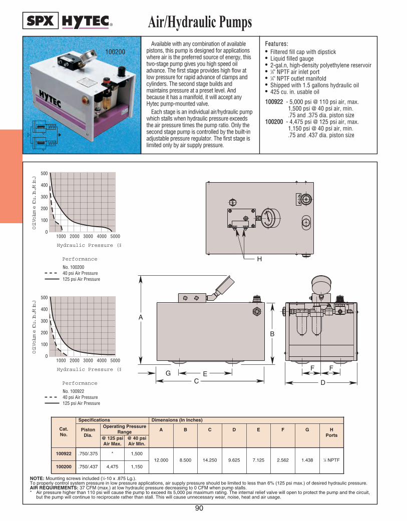
Air/
Hyd
raul
ic P
umps
90
Available with any combination of availablepistons, this pump is designed for applicationswhere air is the preferred source of energy, thistwo-stage pump gives you high speed oiladvance. The first stage provides high flow atlow pressure for rapid advance of clamps andcylinders. The second stage builds andmaintains pressure at a preset level. Andbecause it has a manifold, it will accept anyHytec pump-mounted valve.
Each stage is an individual air/hydraulic pumpwhich stalls when hydraulic pressure exceedsthe air pressure times the pump ratio. Only thesecond stage pump is controlled by the built-inadjustable pressure regulator. The first stage islimited only by air supply pressure.
FFeeaattuurreess::• Filtered fill cap with dipstick• Liquid filled gauge• 2-gal.n, high-density polyethylene reservoir• 1⁄4" NPTF air inlet port• 1⁄4" NPTF outlet manifold • Shipped with 1.5 gallons hydraulic oil• 425 cu. in. usable oil
110000992222 - 5,000 psi @ 110 psi air, max.1,500 psi @ 40 psi air, min..75 and .375 dia. piston size
110000220000 - 4,475 psi @ 125 psi air, max.1,150 psi @ 40 psi air, min..75 and .437 dia. piston size
Air/Hydraulic Pumps
1000 2000 3000 4000 5000
500
400
300
200
100
0
Hydraulic Pressure (PSI)
Oil Volume (Cu. In./Min.)
Performance
No. 10020040 psi Air Pressure125 psi Air Pressure
1000 2000 3000 4000 5000
500
400
300
200
100
0
Hydraulic Pressure (PSI)
Oil Volume (Cu. In./Min.)
Performance
No. 10092240 psi Air Pressure125 psi Air Pressure
A
D
B
EC
GF F
H
100200
NOTE: Mounting screws included (1⁄4-10 x .875 Lg.).To properly control system pressure in low pressure applications, air supply pressure should be limited to less than 6% (125 psi max.) of desired hydraulic pressure.AIR REQUIREMENTS: 37 CFM (max.) at low hydraulic pressure decreasing to 0 CFM when pump stalls.* Air pressure higher than 110 psi will cause the pump to exceed its 5,000 psi maximum rating. The internal relief valve will open to protect the pump and the circuit,
but the pump will continue to reciprocate rather than stall. This will cause unnecessary wear, noise, heat and air usage.
Cat.No.
Specifications Dimensions (In Inches)
100200
G
.750/.4371.438
Piston Dia.
Operating PressureRange A B C D E
4,475
F
1,150
HPorts
1⁄4 NPTF
@ 125 psiAir Max.
@ 40 psiAir Min.
100922 .750/.375 * 1,50012.000 8.500 14.250 9.625 7.125 2.562
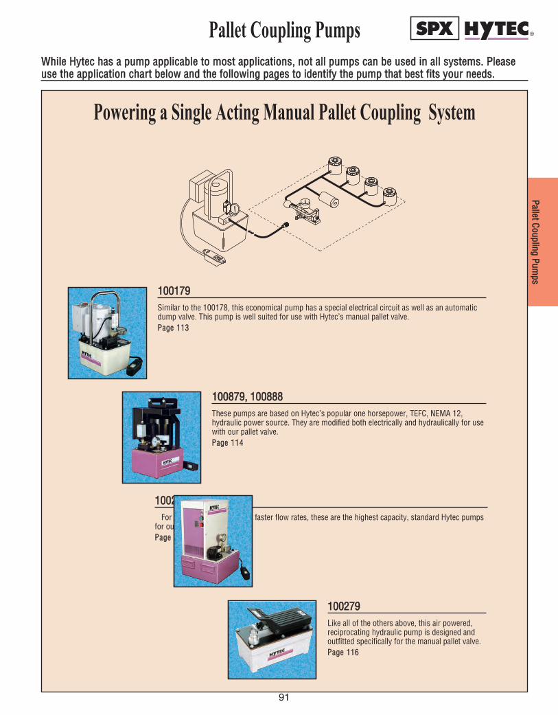
PPaalllleett CCoouupplliinngg PPuummppss
91
Pallet Coupling Pumps
110000117799Similar to the 100178, this economical pump has a special electrical circuit as well as an automaticdump valve. This pump is well suited for use with Hytec’s manual pallet valve.PPaaggee 111133
110000887799,, 110000888888These pumps are based on Hytec’s popular one horsepower, TEFC, NEMA 12,hydraulic power source. They are modified both electrically and hydraulically for usewith our pallet valve.PPaaggee 111144
110000221122,, 110000222211For larger systems requiring faster flow rates, these are the highest capacity, standard Hytec pumps
for our manual pallet valve.PPaaggee 111155
110000227799Like all of the others above, this air powered,reciprocating hydraulic pump is designed andoutfitted specifically for the manual pallet valve.PPaaggee 111166
Powering a Single Acting Manual Pallet Coupling System
WWhhiillee HHyytteecc hhaass aa ppuummpp aapppplliiccaabbllee ttoo mmoosstt aapppplliiccaattiioonnss,, nnoott aallll ppuummppss ccaann bbee uusseedd iinn aallll ssyysstteemmss.. PPlleeaasseeuussee tthhee aapppplliiccaattiioonn cchhaarrtt bbeellooww aanndd tthhee ffoolllloowwiinngg ppaaggeess ttoo iiddeennttiiffyy tthhee ppuummpp tthhaatt bbeesstt ffiittss yyoouurr nneeeeddss..

CONTROLVALVES
DDIIRREECCTTIIOONNAALL
PPRREESSSSUURREE
FFLLOOWW
92

93
Control ValveInformation
Hytec has created a line of controlvalves designed and manufactured soprecisely that there is virtually zeroleakage, making them ideal for con-stant pressure hydraulic workholdingsystems. VVaallvveess wwiitthh iinntteerrnnaall lleeaakk--aaggee ((ssuucchh aass ssppooooll vvaallvveess)) aarree nnoottaapppprroopprriiaattee ffoorr uussee wwiitthh HHyytteeccppuummppss aanndd ppaalllleett vvaallvvee ssyysstteemmss..
DDiirreeccttiioonnaall CCoonnttrrooll VVaallvveess Available in many versions, each of these
valves is capable of operating double or single-acting spring return systems. Mounting config-urations available are pump mounted, remotemounted, and manifold mounted, and operationis either manual or through electric solenoids.
Manually operated valves are used in appli-cations where the valves can be mountednear the operator on the fixture, pump, orany convenient location at the workstation.The electrically operated valve is ideal forsystems requiring push-button simplicity orautomated systems where the valve is con-trolled by machine logic instead of the opera-tor. Since it’s controlled by an electrical sig-nal, it can be mounted in any convenientlocation and need not take up valuable fixtureor workstation space.
All remote mounted directional controlvalves are installed by connecting the pumpor pressure port (labeled “P”) to the pressuresource and the return or tank port (labeled“T”) to the return line. The outlets or workports (labeled “A” and “B”) are connected tothe component or system to be controlled.
In single-acting systems, the valves areused as 3-way valves. One port, A or B, isplugged and the other is connected to a sin-gle-acting actuator or system. In one handleposition, the port to the actuator will be pres-surized and the plugged port open to thereservoir. In the other handle position, theactuator will retract because that port is opento the reservoir. This pressurizes the remain-ing port, but since it’s plugged, the pump willbuild pressure and shut off.
In double-acting systems, these valves actas 4-way valves: ports A and B are connectedto a double-acting actuator or system. Inhandle position A, port A is pressurized andport B is open to the reservoir. Handle posi-tion B pressurizes port B and port A is opento the reservoir. Shifting the valve will causethe actuator to alternately extend and retract.
Selected Hytec remote mounted directionalcontrol valves include a check valve in thepressure port to maintain system pressureduring periods of fluctuating supply pressure.Carefully review check valve requirements oneach product selected. With pump mountedvalves, the pump outlet check valve servesthe same purpose.
PPrreessssuurree CCoonnttrrooll VVaallvveessTwo types are available for specialized
workholding systems – sequence and pres-sure reducing. Both are available in manifoldand conventionally mounted styles.
PPrreessssuurree SSeeqquueennccee VVaallvveess control theorder of events within a hydraulic system bydirecting pressure into two circuits in a pres-sure-controlled sequence. For example, thisallows clamps to be actuated before worksupports are locked.
Initially, the valve is closed. Oil flows to theprimary circuit until pressure reaches thevalve setting. The valve then opens to deliveroil to the secondary circuit while holdingpressure on the primary circuit. Once sec-ondary and primary pressures are equal, thepressure increases uniformly in both circuits.
This valve is installed by connecting the pres-sure port (labeled “P”) to a tee in the portion ofthe circuit to be actuated first. The part of thecircuit to be sequenced later is connected to theoutlet port (labeled “A”). The vent port must beopen to atmosphere for proper operation.
PPrreessssuurree RReedduucciinngg VVaallvveess are designed toreduce the maximum pressure in a portion ofa hydraulic circuit – the need for a separatepower source for each pressure level is elimi-nated. The valve is open from the inlet to theoutlet until a pre-selected pressure isreached, at which point the valve closes tolimit pressure in the secondary circuit. Valveseats and poppets are precision ground,assuring virtually zero leakage and eliminatingthe need for a case drain line.
This valve is connected “in line” with thecircuit requiring the reduced pressure. Theinlet or pressure port (labeled “P”) is on thehigh pressure side. The outlet or reducedpressure port (labeled “A”) is connected tothe lower pressure circuit. The drain or tankport (labeled “T”) is connected to the powersource return line if necessary. Ordinary pres-sure limiting valves close when their pressuresetting is reached. Once closed, it will not re-open until system pressure is released. Evenminor leakage in the system can not be madeup. Hytec’s pressure reducing valve uses abalanced poppet design which will re-openany time flow downstream is required.
FFllooww CCoonnttrrooll VVaallvveessThe types of flow control valves available
from Hytec are: pilot operated check valve andneedle-type flow restrictor valves.
Hytec’s PPiilloott OOppeerraatteedd CChheecckk VVaallvvee offers aunique poppet seal design making it ideal forpallet applications or other specialized controlcircuits where zero leakage is essential. It canbe used in any application where pressuremust be maintained in a portion of a circuituntil a separate pilot signal opens the valveand allows free flow in the reverse direction.
This 5,000 psi valve is used with Hytec’sAutomatic Pallet Coupling System and double-acting manual pallet valve. Replaceable filterelements protect the check valve and yourother system components from contamina-tion. No disassembly of circuit plumbing isrequired to service the filters or check valvecartridges.
When the port labeled “INLET” is pressur-ized, hydraulic fluid can flow freely into thevalve, leaving through the port labeled “OUT-LET”. Pressurized fluid at the outlet port can-not flow back into the valve unless the portlabeled “PILOT” is pressurized to open thevalve allowing reverse flow.
NNeeeeddllee VVaallvveess are multiple-turn flowrestrictor valves which provide finelyadjustable flow control for components or cir-cuits requiring reduced flow rates. They arealso used in some non-critical sequencingapplications where restriction in part of a cir-cuit will tend to cause the actuators in theremainder of the circuit to operate first.
Needle valves are available that: a) restrict flow in both directions, orb)restrict flow in one direction through the
use of an internal free-flow check valve.Valves without the free-flow check are typi-
cally used in a part of a circuit where there isflow in only one direction. They can also beused in double-acting circuits where restric-tion is desirable in both directions.
Valves with the reverse free-flow check aremost effectively used in single-acting circuitswhere the actuation speed must be reducedwithout affecting the system return time.
Our high pressure BBaallll VVaallvveess provide fullunrestricted flow and positive shut-off of flu-ids. They have a 90 degree actuation and areavailable in SAE or NPT ports.
CCoonnttrrooll VVaallvvee IInnffoorrmmaattiioonn
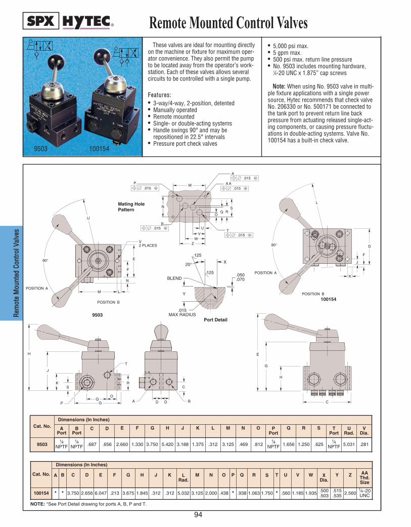
94
RReemm
oottee
MMoouu
nntteedd
CCoonn
ttrrooll
VVaall
vveess
These valves are ideal for mounting directlyon the machine or fixture for maximum oper-ator convenience. They also permit the pumpto be located away from the operator’s work-station. Each of these valves allows severalcircuits to be controlled with a single pump.
FFeeaattuurreess::• 3-way/4-way, 2-position, detented• Manually operated• Remote mounted• Single- or double-acting systems• Handle swings 90° and may be
repositioned in 22.5° intervals• Pressure port check valves
• 5,000 psi max.• 5 gpm max.• 500 psi max. return line pressure• No. 9503 includes mounting hardware,
1⁄4-20 UNC x 1.875” cap screws
NNoottee:: When using No. 9503 valve in multi-ple fixture applications with a single powersource, Hytec recommends that check valveNo. 206330 or No. 500171 be connected tothe tank port to prevent return line backpressure from actuating released single-act-ing components, or causing pressure fluctu-ations in double-acting systems. Valve No.100154 has a built-in check valve.
Remote Mounted Control Valves
9503 100154
NOTE: *See Port Detail drawing for ports A, B, P and T.
90°
POSITION A
L
K
J
F
D
E
G
H
C
POSITION B
90°
POSITION A
U
M
F
E
H
J
K
G
N
L
V2 PLACES
S
QO
P
R
D D
C
BA
T
POSITION B
N
M
U T
.015 M
.015 M
.015 M
.015 M
.015 M
Z W
V
O Q
S R
B
A A P
A
Port Detail
Mating HolePattern
9503
100154
20 °
125
125
Y
.050
.070
.015 MAX RADIUS
BLEND
X
Cat. No.Dimensions (In Inches)
APort
BPort
C D E F G H J K L M N O PPort
Q R S TPort
URad.
VDia.
95031⁄4
NPTF1⁄4
NPTF .687 .656 2.660 1.330 3.750 5.420 3.188 1.375 .312 3.125 .469 .8121⁄4
NPTF 1.656 1.250 .6251⁄4
NPTF 5.031 .281
Cat. No.
Dimensions (In Inches)
A B C D E F G H J K LRad.
M N O P Q R S T U V W XDia.
Y Z AAThd.Size
100154 * * 3.750 2.656 6.047 .213 3.675 1.845 .312 .312 5.032 3.125 2.000 .438 * .938 1.063 1.750 * .560 1.185 1.935 .500.503
.515
.535 2.5601⁄4–20UNC
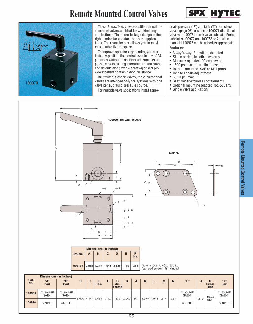
RReemm
oottee MMoouunntteedd CCoonnttrrooll VVaallvveess
These 3-way/4-way, two-position direction-al control valves are ideal for workholdingapplications. Their zero-leakage design is theright choice for constant pressure applica-tions. Their smaller size allows you to maxi-mize usable fixture space.
To improve operator ergonomics, you caninstantly position the control lever in any of 24positions without tools. Finer adjustments arepossible by loosening a locknut. Internal stopsand detents along with a shaft wiper seal pro-vide excellent contamination resistance.
Built without check valves, these directionalvalves are intended oonnllyy for systems with onevalve per hydraulic pressure source.
For multiple valve applications install appro-
priate pressure ("P") and tank ("T") port checkvalves (page 96) or use our 100971 directionalvalve with 100974 check valve subplate. Portedsubplates 100972 and 100973 or 2-stationmanifold 100975 can be added as appropriate.FFeeaattuurreess::• 3-way/4-way, 2-position, detented• Single or double acting systems• Manually operated, 90 deg. swing• 1500 psi max. return line pressure• Remote mounted, SAE or NPT ports• Infinite handle adjustment• 5,000 psi max.• Shaft wiper excludes contaminants• Optional mounting bracket (No. 500175)• Single valve applications
Remote Mounted Control Valves
Cat. No.
Dimensions (In Inches)
7⁄16-20UNFSAE-4
1⁄4 NPTF
7⁄16-20UNFSAE-4
1⁄4 NPTF 1⁄4 NPTF
7⁄16-20UNFSAE-4
1⁄4 NPTF
7⁄16-20UNFSAE-4
"A"Port
2.400 4.444
100969
1009702.480 .442 .375 2.000 .947 1.375 1.948 .974 .287 .313 10-24
UNC
C D ERad.
F H J K L M N Q RThread
size
"P" "T"Port
GMin.
Thread
"B"Port
Cat. No.
Dimensions (In Inches)
A
2.565500175 1.375 1.948 .119 .2813.138
C D E FDia.
B
Note: #10-24 UNC x .375 Lg. flat head screws (4) included.
100970
E
T
AG
D
P
B
J
Q
R
K
C
H
E
AK
L
NM
D
B
A
F
C
F
A B
P T
100969 (shown), 100970
500175
95

CChheecc
kk VVaa
llvveess
96
Both the 1⁄4 NPT “T” Port Check Valve (partnumber 500171) and the SAE-4 (part num-ber 500173) are recommended on singleacting circuits where there is more than onedirectional valve per power source. Thesecheck valves are ideal for use in circuitswhere return line pressure fluctuations mayaffect released clamps. Use this anytime areturn line pressure spike could causeunclamped actuators to move and affectoperator safety. They are designed specifi-cally for Hytec’s No. 100969 and No.100970 Directional Control Valves.
The 1⁄4 NPT (500172) and the SAE-4(500174) “P” port check valves are requiredon all single acting or double acting circuitswhere there is more than one directionalvalve per power source. These check valvesprevent power source pressure fluctuationsfrom affecting the pressure in clamped cir-cuits. Without this check valve, shifting thedirectional control valve in one circuit willcause a temporary loss of clamping pres-sure in the other circuit.
Check Valves
“P” Port Check Valve(500172, 500174)
“T” Port Check Valve(500171, 500173)
D
AC
E
D
A
B
C
E
D
A
Free Flow
B
C
E
Free Flow
Free Flow
Free Flow
D
AC
E
500171100970
1.349– 1⁄4 NPTF 1⁄4 NPTF .750
500172 1.259
Use With Directional Valve No.
A B CThread
Size
500173100969
1.431 1.0717⁄16-20UNF
SAE-47⁄16-20UNF
SAE-4 .625500174
DThread
Size
1.065 .705
EHex
Cat. No.
Specifications
Check Valve
Location
Outlet
Inlet
Outlet
Inlet
CrackingPressure
(psi)
2
500171
D
AC
E
D
A
B
C
E
D
A
Free Flow
B
C
E
Free Flow
Free Flow
Free Flow
D
AC
E
D
AC
E
D
A
B
C
E
D
A
Free Flow
B
C
E
Free Flow
Free Flow
Free Flow
D
AC
E
D
AC
E
D
A
B
C
E
D
A
Free Flow
B
C
E
Free Flow
Free Flow
Free Flow
D
AC
E
500173 500174500172
500171500172
500173500174
Dimensions (In Inches)
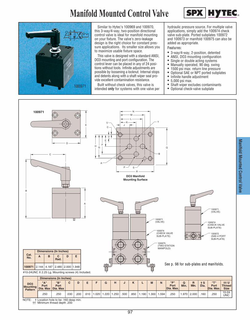
97
MMaanniiffoolldd MM
oouunntteedd CCoonnttrrooll VVaallvvee
Similar to Hytec’s 100969 and 100970,this 3-way/4-way, two-position directionalcontrol valve is ideal for manifold mountingon your fixture. The valve’s zero-leakagedesign is the right choice for constant pres-sure applications. Its smaller size allows youto maximize usable fixture space.
This valve is designed with a standard ANSI,DO3 mounting and port configuration. Thecontrol lever can be placed in any of 24 posi-tions without tools. Infinite adjustments arepossible by loosening a locknut. Internal stopsand detents along with a shaft wiper seal pro-vide excellent contamination resistance.
Built without check valves, this valve isintended oonnllyy for systems with one valve per
hydraulic pressure source. For multiple valveapplications, simply add the 100974 checkvalve sub-plate. Ported subplates 100972and 100973 or manifold 100975 can also beadded as appropriate.FFeeaattuurreess::• 3-way/4-way, 2-position, detented• ANSI, DO3 mounting configuration• Single or double acting systems• Manually operated, 90 deg. swing• 1500 psi max. return line pressure• Optional SAE or NPT ported subplates• Infinite handle adjustment• 5,000 psi max.• Shaft wiper excludes contaminants• Optional check-valve subplate
Manifold Mounted Control ValveA B
P T
100971
NOTE: † Location hole to be .160 deep min.†† Minimum thread depth .200
DO3MountingPattern
Dimensions (In Inches)
.250 .250.250
"A"Port
Dia. Max
.030 .200 .610 1.020 1.220 1.250 .500 .850 1.190 1.300 1.594 1.97010-24UNC2.000 .160
C D E F H J K L M N QMin.
RMin.
"P"Port
Dia. Max.
"T"Port
Dia. Max.
† SDia.
†† UThread
Size
G"B"Port
Dia. Max
.250
Cat.No.
Dimensions (In Inches)
2.144100971 4.187
A
2.480 2.000 1.948
CRad.
D EB
DO3 ManifoldMounting Surface
100971
Q
BC
E
D
B
A
A
SP
R
JK
L
N
M
T
H
E
G
D
F
C
U
100975(TWO-STATIONMANIFOLD)
100971(VALVE)
100974(CHECK VALVESUB-PLATE)
100972(SAE-4 PORTSUB-PLATE)
100974(CHECK VALVESUB-PLATE)
100971(VALVE)
SSeeee pp.. 9988 ffoorr ssuubb--ppllaatteess aanndd mmaanniiffoollddss..
#10-24UNC X 2.25 Lg. Mounting screws (4) Included.

98
CCoonntt
rrooll VV
aallvvee
AAcccc
eessssoo
rriieess
SSiinnggllee--ssttaattiioonn SSuubb--PPllaatteess NNoo.. 110000997722 aanndd 110000997733
These D03 sub-plates are for use with the100971 directional control valve and 100974check valve sub-plate. These assemblies willprovide conventionally ported, remote mount-ed, directional control valves for use in multi-ple valve systems. These sub-plates may alsobe used with the 100971 directional controlvalve only in single valve systems. (For singlevalve applications, consider using valves100969 and 100970.) Optional mountingbracket (No. 500175) is available (see p. 95). TTwwoo--SSttaattiioonn MMaanniiffoolldd NNoo.. 110000997755
This manifold provides for mounting two,100971 directional control valves. Externalplumbing is reduced because both DO3
mounting patterns share the same pressureand tank ports. Check valve sub-plate 100974must also be used in workholding circuits.CChheecckk VVaallvvee SSuubb--PPllaattee NNoo.. 110000997744
Use this in directional control valve in appli-cations requiring inlet and outlet checks.(Ports P and T) When two or more valves areconnected to the same pressure source, thesecheck valves prevent pressure fluctuations inone system from affecting the other. Withoutthis check valve sub-plate, the shifting of onevalve in a system can cause the loss of clamp-ing pressure in another. This check valve sub-plate uses the same DO3 mounting configura-tion as our 100971 directional control valve. Itis simply placed underneath the valve.Mounting screws are included.
100974
100975
100972
Cat. No.
Dimensions (In Inches)
1009753⁄4-16UNF
SAE-87⁄8-14UNFSAE-10
7⁄8-14UNFSAE-10
3⁄4-16UNFSAE-8
"A"Port
5.630 .630 1.500 2.380 3.000 1.060 2.130 4.250 .810 2.190 3.000 2.38
C D E F H J K L M N "P"Port
"T"Port
UG"B"Port
Control Valve Accessories
SURFACED03 MATING
100974100972 (SHOWN), 100973
E
C
D
L
ENM
D
K
J
F
H
G
G
C
P
P
T
BA
100975
T
HJ
T
P N
M
L
K
G
F
E
D
C
B
A
5/16-18UNC X 5/8 LG.BOLTS INCLUDED
PU
D03 Mating Surface (See page 94 for details)
(See page 94 for details)
Dimensions (In Inches)Cat. No.
"A"Port
"B"Port
C D E F GMtng.
HMtng.
J KMtng.
LThread
Size
MMin.
Thread
N "P"Port
"T"Port
1009727⁄16-20 UNF
SAE-47⁄16-20 UNF
SAE-4
2.00 1.948.904 .947 1.375 .313 .974 .287 10-24
UNC .260 .452
7⁄16-20 UNFSAE-4
7⁄16-20 UNFSAE-4
100973 1⁄4 NPTF 1⁄4 NPTF 1⁄4 NPTF 1⁄4 NPTF
100974† — — .997 — — — — — — — — — —
NOTE: † 100974 Check Valve includes (4) #10-24 UNC x 3.25 Lg. Mounting Screws.

99
PPuummpp MM
oouunntteedd CCoonnttrrooll VVaallvvee
Designed to be used in applications wherethe pump is located near the operator withthe valve mounted directly on the pump. Thisconfiguration eliminates the need for pres-sure and return lines between the pump andremote mounted control valves. It willreplace the outlet manifold on most Hytecconstant pressure pumps having that fea-ture. (For use with Hytec No. 100178 pump,contact Hytec Technical Services.) Onepump/valve combination is required for eachcircuit to be controlled.
FFeeaattuurreess::• 3-way/4-way, 2-position, detented• Manually operated• Pump mounted• Handle swings 90° and can be reposi-
tioned in 22.5° intervals• Single- or double-acting systems• 1⁄4” NPTF reducer bushing• Includes mounting hardware, return tube• 5,000 psi max.• 5 gpm max.
Pump Mounted Control Valve
9504
1⁄4NPTF
.937 .750 3.188 5.562 3.750 2.660 .531 .812 1.437 5.0311⁄4NPTF
1⁄4NPTF
GGauge-Port
Cat. No.
Dimensions (In Inches)
F H J NRad.
K L MDC EAPort
BPort
B
A
POSITION B
POSITION A
90°
N
C
C
H
M
D
E
F
K J
L
G
9504
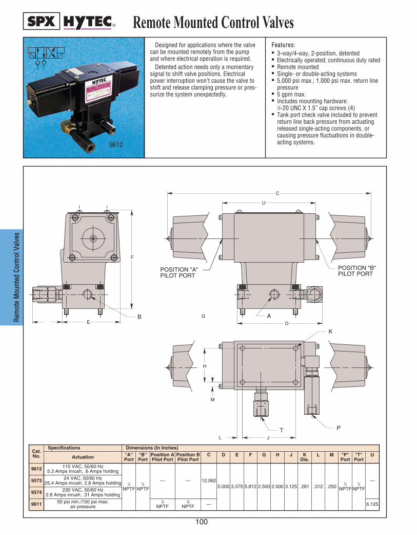
100
RReemm
oottee
MMoouu
nntteedd
CCoonn
ttrrooll
VVaall
vveess
Remote Mounted Control ValvesDesigned for applications where the valve
can be mounted remotely from the pumpand where electrical operation is required.
Detented action needs only a momentarysignal to shift valve positions. Electricalpower interruption won’t cause the valve toshift and release clamping pressure or pres-surize the system unexpectedly.
FFeeaattuurreess::• 3-way/4-way, 2-position, detented• Electrically operated; continuous duty rated• Remote mounted• Single- or double-acting systems• 5,000 psi max.; 1,000 psi max. return line
pressure• 5 gpm max.• Includes mounting hardware:
1⁄4-20 UNC X 1.5” cap screws (4)• Tank port check valve included to prevent
return line back pressure from actuatingreleased single-acting components, orcausing pressure fluctuations in double-acting systems.
PILOT PORTPOSITION "B"
PILOT PORTPOSITION "A"
JL
PT
H
M
K
U
C
AD
B
F
EG
9612
Cat.No.
Specifications Dimensions (In Inches)
Actuation “A”Port
“B”Port
Position APilot Port
Position BPilot Port
C D E F G H
9612 115 VAC, 50/60 Hz5.3 Amps inrush, .6 Amps holding
1⁄4NPTF
1⁄4NPTF
— — 12.0625.000 3.375 5.812 2.500 2.000
9573 24 VAC, 50/60 Hz25.4 Amps inrush, 2.8 Amps holding
3.125
J
.281
KDia.
.312
L
.250
M
1⁄4NPTF
"P"Port
1⁄4NPTF
"T"Port
—
U
9574 230 VAC, 50/60 Hz2.8 Amps inrush, .31 Amps holding
9611 50 psi min./150 psi max.air pressure
1⁄8NPTF
1⁄8NPTF — 6.125
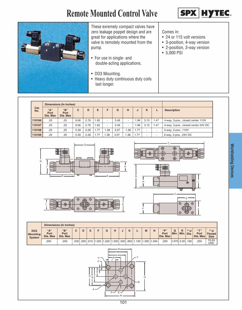
K
DC
K
RP S
B
Q
TJ
U
C
D
FE
G
A
H
KLM
N
G
J H
D
C
G
H J
L E
F J
K
DC
K
RP S
B
Q
TJ
U
C
D
FE
G
A
H
KLM
N
G
J H
D
C
G
H J
L E
F J
WWoorrkkhhoollddiinngg DD
eevviicceess
These exremely compact valves havezero leakage poppet design and aregreat for applications where thevalve is remotely mounted from thepump.
• For use in single- and double-acting applications.
• DO3 Mounting.• Heavy duty continuous duty coils
last longer.
Comes in:• 24 or 115 volt versions• 3-position, 4-way version• 2-position, 3-way version• 5,000 PSI
Remote Mounted Control Valve
110166 .25 .25 9.06 2.76 1.92 - 3.46 - 1.96 3.15 1.47 4-way, 3-pos., closed center 110V
110167 .25 .25 9.06 2.76 1.92 - 3.46 - 1.96 3.15 1.47 4-way, 3-pos., closed center 24V DC
110168 .25 .25 5.39 2.28 1.77 1.38 3.07 1.38 1.77 - - 3-way, 2-pos., 110V
110169 .25 .25 5.39 2.28 1.77 1.38 3.07 1.38 1.77 - - 3-way, 2-pos., 24V DC
“A”Port
Dia. Max
“B”Port
Dia. Max
LJHGFEDC KCat.No.
Dimensions (In Inches)
Description
.250 .250 .030 .200 .610 1.020 1.220 1.250 .500 .850 1.190 1.300 1.594 .250 1.970 2.00 .160 .250 10-24UNC
“A”Port
Dia. Max
“B”Port
Dia. Max
L M N “P”Port
Dia. Max
QMin.
RMin.
†† UDia.
“T”Port
Dia. Max
†† UThread
Size
JHGFEDC KDO3MountingSystem
Dimensions (In Inches)
101

Pressure Sequence Control Valves
102
PPrreess
ssuurree
SSeeqq
uueenncc
ee VVaa
llvveess
Sequence valves control the order ofevents within a hydraulic system by directingpressure to the two circuits in a pressure-controlled sequence. For example, thisallows clamps to be actuated before worksupports are locked.
Initially, the valve is closed. Oil flows to theprimary circuit until pressure reaches thevalve setting. The valve then opens to deliveroil to the secondary circuit while holdingpressure on the primary circuit. Once sec-ondary and primary pressures are equal, thepressure increases uniformly in both circuits.There is no reduction of pressure available toeither circuit.
FFeeaattuurreess::• Sequence pressure range is adjustable
from 0 to 4,000 psi• Usable with hydraulic systems operating
up to 5,000 psi• Will not reduce pressure to the
secondary circuit• Minimum operation pressure should be
120% of sequence pressure setting• Internal check valve allows free flow in
reverse direction• Maximum flow rate 5 gpm• Suitable for single- and double-acting circuits• NPT, SAE or manifold mounting
Cat. No.
Dimensions (In Inches)"A"Port
B C D E F G H JDia.
K L M N O "P"Port
Q
9613 1⁄4 NPTF
2.750 3.281 1.000 .250 .250 2.781 2.250 .281 1.375 1.040 1.500 2.000 5.000
1⁄4 NPTF
.312100943
7⁄16-20UNFSAE-4
7⁄16-20UNFSAE-4
9613
100129
Dimensions (In Inches)
100129 * 5.250 1.375 2.500 .312 .625 2.645 1.960 1.520 1.000 .456 1.063 1.560 1.875 * 1⁄4-20 UNC
NOTE: *See Port Detail drawing for Ports A and P.
Q XDia.
.500
.503.515.535
Cat. No. A B C D E F G H J K L M N O P Y
CLAMP
WORKSUPPORT
SEQUENCE VALVE
DIRECTIONALCONTROLVALVE
A
P
K J
H G
A
P
L M
N O
Q
.015 M
.015 M
2 PLACES
1/8 VENT HOLE
.002 M
POR T (X-Y)
2 PLACES
20 °
125
125
Y
.050
.070
.015 MAX RADIUS
BLEND X
O
D
K
H
B
F Q
G C
P
VENT
E
J
A N M
L
B
F
E
P
A
D
C
100129
9613100943
MatingHole
Pattern
Port Detail

103
PPrreessssuurree RReedduucciinngg VVaallvveess
Pressure reducing valves are designed toreduce the maximum pressure in a portion ofa hydraulic circuit: the valve is open from theinlet to the outlet until a pre-selected pres-sure is reached, at which point the valvecloses to limit pressure in the secondary cir-cuit. The need for a separate power sourcefor each pressure level is eliminated.
Valves seats and poppets are precisionground, assuring virtually zero leakage andeliminating the need for a case drain line.The drain port (T) is used only during set upof the internal safety relief valve. Thisadjustable relief valve can be set to justabove the reduced pressure setting so it willopen only if contamination or another mal-
function prevents the pressure reducingvalve from closing, causing the outlet pressure to rise above the relief valve setting. The drain port should never beplugged, although it is seldom permanentlyplumbed into the circuit.FFeeaattuurreess::• Valves are adjustable from 1,000 to 5,000
psi outlet pressure• Internal check valve allows free flow in
reverse direction• Maximum flow rate at 5 gpm• NPT, SAE or manifold mount• Automatically reopens to replenish lost
pressure
Cat.No.
Dimensions (In Inches)"A"Port
B C D E F G H J K L MDia.
N O "P"Port
Q "T"Port
U
9608 1⁄4 NPTF
1⁄4 NPTF
3.062 3.000 4.062 1.500 6.312 1.438 .375 .375 1.188
3.312
3.321
.281 1.000
1.938
2.000
1⁄4 NPTF
1⁄4 NPTF**
.625
1⁄8 NPTF
1.820
1009427⁄16-20UNF
SAE-4
7⁄16-20UNFSAE-4
7⁄16-20UNFSAE-4
7⁄16-20UNFSAE-4**
1⁄4 NPTF**
7⁄16-20UNFSAE-4**
7⁄16-20UNFSAE-4
E
F
A
M
T
Q
G
BLD
J
H N
KO
C
P
U
Pressure Reducing Control Valves
100128
9608
100128 * 2.645 7.000 4.000 1.750 2.960 2.188 1.875 1.750 1.560 .456 .316 1.520 1.960 * 1⁄4-20 UNC * 1.875
Dimension (In Inches)Cat. No. Q
Thread SizeX
Dia.YTPN OL MJF KHGC D EA B
NOTE: *See Port Detail drawing for ports A, P and T.
NOTE: **Include filters on P port and T port.
.500
.503.515.535
Z
DIRECTIONALCONTROLVALVES
PRIMARYCIRCUIT
SECONDARY[REDUCEDPRESSURE]CIRCUIT
PRESSUREREDUCINGVALVE
A
T
P
NO
B
ML
KJ
H
Q.015 M
2 PLACES
.002 M
PORT (X-Y)
3 PLACES
Mating Hole Pattern
20 °
125
125
Y
.050
.070
.015 MAX RADIUS
BLEND X
Port Detail
9608100942110156110157
C G
F D
T
P
A
E Z
100128
A T
P
110156
110157

Pilot Operated Check Valves
104
CChheecc
kk VVaa
llvveess
Hytec’s pilot operated check valve offers aunique poppet seal design making them ideal forpallet applications or other specialized controlcircuits where zero leakage is essential. They canbe used in any application where pressure mustbe maintained in a portion of a circuit until a sep-arate pilot signal opens the valve and allows freeflow in the reverse direction.
The pilot pressure required to release thevalves is approximately one third of the pres-sure being released. The pilot piston is sealedto prevent pilot flow through the valve.
These valves are used with Hytec’sAutomatic Pallet Coupling System and dou-ble-acting manual pallet valve. The replace-able filter elements protect the check valveand your other system components from con-
tamination. No disassembly of circuit plumb-ing is required to service the filters or thecheck valve cartridge. An additional filter isrecommended for protection of the returnside of double-acting clamping circuits.FFeeaattuurreess::• Replaceable, cartridge design valve• Filters in all three ports protect the check
valve and downstream components• Filters are replaceable without disassembly
of plumbing• SAE O-rings ports• 10 micron (25 micron absolute) filtration level• Specially reinforced filter elements resist
fatigue from pressure spikes• 5,000 psi maximum• No. 100915 replaces and directly inter-
changes with No. 100856
100915
100915 1.955
Cat. No. QN
Dimension (In Inches)
MDia.
PKH J L
.219 .281 .312 .050 .750
Cat. No.
100915
MaximumFlow
(GPM)
System/Pilot Pressure
Ratio
APilotPort
5 3:1
Specifications
BInletPort
COutlet
SAE-69⁄16-18 UNF
SAE-47⁄16-20 UNF
SAE-69⁄16-18 UNF 1.1251.125.7811.500
4.000 3.562
D E F G
Dimensions (In Inches)
C
Q
B A
F G
D
E
L
J H
K P
N
M
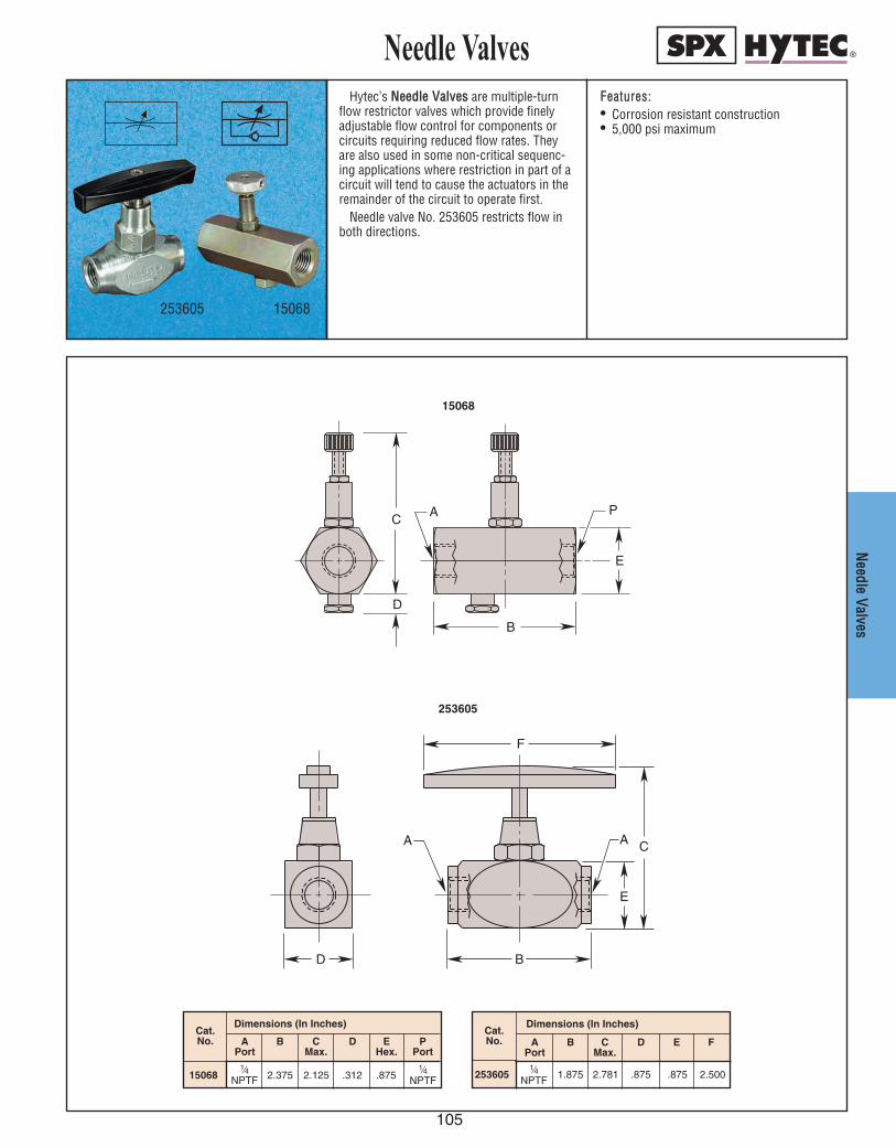
105
NNeeeeddllee VVaallvveess
Needle ValvesHytec’s NNeeeeddllee VVaallvveess are multiple-turn
flow restrictor valves which provide finelyadjustable flow control for components orcircuits requiring reduced flow rates. Theyare also used in some non-critical sequenc-ing applications where restriction in part of acircuit will tend to cause the actuators in theremainder of the circuit to operate first.
Needle valve No. 253605 restricts flow inboth directions.
FFeeaattuurreess::• Corrosion resistant construction• 5,000 psi maximum
253605 15068
253605 1.875 2.781 .875 .875 2.500
Dimensions (In Inches)
ECMax.
1⁄4 NPTF
D FCat. No. A
PortB
Dimensions (In Inches)
15068 2.375 2.125 .312 .875
Cat. No. E
Hex.DC
Max.BA
PortP
Port1⁄4
NPTF1⁄4
NPTF
D
C A
B
E
P
E
C A A
D B
F
15068
253605
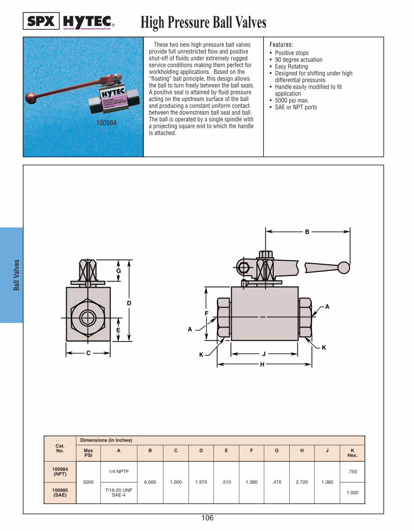
High Pressure Ball Valves
106
BBaallll
VVaallvv
eess
These two new high pressure ball valvesprovide full unrestricted flow and positiveshut-off of fluids under extremely ruggedservice conditions making them perfect forworkholding applications. Based on the“floating” ball principle, this design allowsthe ball to turn freely between the ball seals.A positive seal is attained by fluid pressureacting on the upstream surface of the balland producing a constant uniform contactbetween the downstream ball seal and ball.The ball is operated by a single spindle witha projecting square end to which the handleis attached.
FFeeaattuurreess::• Positive stops• 90 degree actuation• Easy Rotating• Designed for shifting under high
differential pressures• Handle easily modified to fit
application• 5000 psi max.• SAE or NPT ports
100984
Cat. No.
Dimensions (In Inches)
100984(NPT)
5000
1/4 NPTF
6.000 1.000 1.970 .510 1.380 .470 2.720 1.380
.750
Max PSI
100985(SAE)
A
7/16-20 UNF SAE-4
B C D E F G H J
1.000
KHex.
H
J
F
A
K
A
KC
E
D
G
B

107
PALLETIZEDSYSTEMS
MMAANNUUAALL PPAALLLLEETT CCOOUUPPLLIINNGG
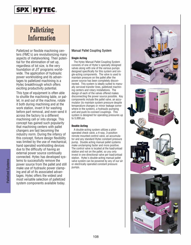
Palletized or flexible machining cen-ters (FMC's) are revolutionizing manyaspects of metalworking. Their poten-tial for the elimination of set up,regardless of lot size, is the veryfoundation of JIT programs world-wide. The application of hydraulicpower workholding and its advan-tages to palletized machining is aHytec breakthrough which offersexciting productivity potential. This type of equipment is often ableto shuttle the machining table, or pal-let, in and out of the machine, rotateit both during machining and at thework station, invert it for washingbefore part removal, and even send itacross the factory to a differentmachining cell or into storage. Thisconcept has gained such popularitythat machining centers with palletchangers are fast becoming theindustry norm. During the infancy ofthis concept, fixture design flexibilitywas limited by the use of mechanical,hand operated workholding devicesdue to the difficulty of having anexternal power source continuallyconnected. Hytec has developed sys-tems to successfully remove thepower source from the pallet and stillmake use of hydraulic power clamp-ing and all of its associated advan-tages. Hytec offers the widest andmost versatile selection of palletizedsystem components available today.
MMaannuuaall PPaalllleett CCoouupplliinngg SSyysstteemm
Single ActingThe Hytec Manual Pallet Coupling System
consists of one of Hytec's specially designedvalves along with one of the various pumpsdesigned specifically for this system and sin-gle-acting components. The valve is used tomaintain pressure on the pallet after thepower source has been completely discon-nected. This system is ideally suited to manu-ally serviced transfer lines, palletized machin-ing centers and rotary installations. Thedesign of each of the valves offered makesdisconnecting the power source possible. Keycomponents include the pallet valve, an accu-mulator (to maintain system pressure despitetemperature changes or minor leakage some-where in the system), a hydraulic pumpingunit and push-to-connect couplings. Thissystem is designed for operating pressures upto 5,000 psi.
Double ActingA double-acting system utilizes a pilot-
operated check valve, a 4-way, 3-positionremote mounted control valve, an accumula-tor and any standard Hytec constant pressurepump. Double acting manual pallet systemsmake unclamping faster and more positive.The control valve is located at the load/unloadstation and not on the pallet, so you onlyinvest in one directional valve per load/unloadstation. Hytec's double-acting manual palletvalve system can be powered by any of our airor electrically operated constant pressurepumps.
108
PalletizingInformation
PPaallllee
ttiizzeedd
SSyyss
tteemm
ss
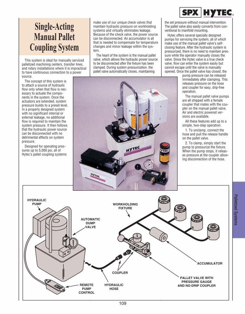
109
PPaalllleettiizzeedd SSyysstteemmss
This system is ideal for manually servicedpalletized machining centers, transfer lines,and rotary installations where it is impracticalto have continuous connection to a powersource.
The concept of this system isto attach a source of hydraulicflow only when that flow is nec-essary to actuate the compo-nents in the system. Once theactuators are extended, systempressure builds to a preset level.In a properly designed systemwith no significant internal orexternal leakage, no additionalflow is required to maintain thesystem pressure. It then followsthat the hydraulic power sourcecan be disconnected with nodetrimental effects on systempressure.
Designed for operating pres-sures up to 5,000 psi, all ofHytec’s pallet coupling systems
make use of our unique check valves thatmaintain hydraulic pressure on workholdingsystems and virtually eliminates leakage.Because of the check valve, the power sourcecan be disconnected. An accumulator is allthat is needed to compensate for temperaturechanges and minor leakage within the sys-tem.
The heart of the system is the manual palletvalve, which allows the hydraulic power sourceto be disconnected after the fixture has beenclamped. During system pressurization, thepallet valve automatically closes, maintaining
Single-Acting Manual Pallet
Coupling System
the set pressure without manual intervention.The pallet valve also easily converts from con-ventional to manifold mounting.
Hytec offers several specially designedpumps for servicing the system, all of whichmake use of the manual pallet valve’s self-closing feature. After the hydraulic system ispressurized, there is no need to maintain pres-sure while the operator manually closes thevalve. Since the Hytec valve is a true checkvalve, flow can enter the system easily butcannot escape until the valve is manuallyopened. Once the pallet valve has closed, the
pump pressure can be releasedimmediately after clamping. Thisreleases pressure on the hoseand coupler for easy, drip-freeoperation.
The manual pallet valve pumpsare all shipped with a femalecoupler that mates with the cou-pler on the manual pallet valve.Air and electric powered ver-sions are available.
All these features add up to asimple, two-step operation:
1. To unclamp, connect thehose and pull the release handleon the pallet valve.
2. To clamp, simply start thepump to pressurize the fixture.When the pump stops, it releas-es pressure at the coupler allow-ing disconnection of the hose.
HYDRAULICHOSE
COUPLER
AUTOMATICDUMPVALVE
WORKHOLDINGFIXTURE
REMOTEPUMP
CONTROL
PALLET VALVE WITHPRESSURE GAUGE
AND NO-DRIP COUPLER
ACCUMULATOR
HYDRAULICPUMP
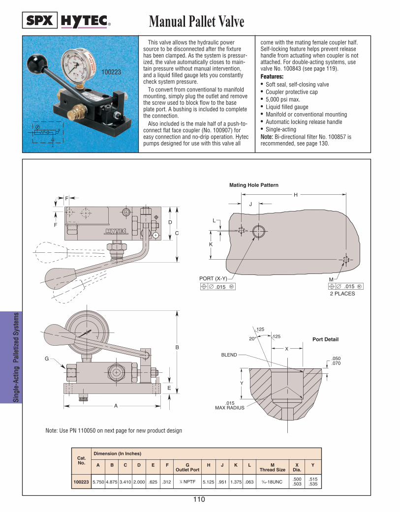
110
SSiinngg
llee--AA
ccttiinn
gg PP
aallllee
ttiizzeedd
SSyyss
tteemm
ss
This valve allows the hydraulic powersource to be disconnected after the fixturehas been clamped. As the system is pressur-ized, the valve automatically closes to main-tain pressure without manual intervention,and a liquid filled gauge lets you constantlycheck system pressure.
To convert from conventional to manifoldmounting, simply plug the outlet and removethe screw used to block flow to the baseplate port. A bushing is included to completethe connection.
Also included is the male half of a push-to-connect flat face coupler (No. 100907) foreasy connection and no-drip operation. Hytecpumps designed for use with this valve all
come with the mating female coupler half.Self-locking feature helps prevent releasehandle from actuating when coupler is notattached. For double-acting systems, usevalve No. 100843 (see page 119).Features:• Soft seal, self-closing valve• Coupler protective cap• 5,000 psi max.• Liquid filled gauge• Manifold or conventional mounting• Automatic locking release handle• Single-actingNNoottee:: Bi-directional filter No. 100857 is recommended, see page 130.
Manual Pallet Valve
100223
A C D E F GOutlet Port
B
100223 5.750 4.875 3.410 2.000 .625 .312 5.125 .951 1.375 .063
Cat. No. H J K M
Thread SizeL X
Dia.Y
Dimension (In Inches)
.500
.503.515.535
5⁄16-18UNC1⁄4 NPTF
F
F
D
C
E
B
G
A
K
L
J
H
M .015
2 PLACES .015
POR T (X-Y) M M
20 °
125
125
Y
.050
.070
.015 MAX RADIUS
BLEND X
Port Detail
Mating Hole Pattern
Note: Use PN 110050 on next page for new product design
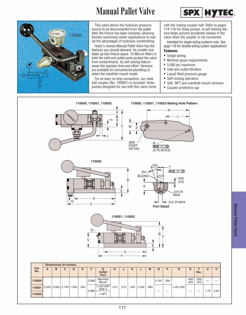
111
MMaannuuaall PPaalllleett VVaallvvee
This valve allows the hydraulic pressuresource to be disconnected from the palletafter the fixture has been clamped, allowingflexible machining center applications to real-ize the advantages of hydraulic workholding.
Hytec’s newest Manual Pallet Valve has thefeatures you should demand. Its smaller sizetakes up less fixture space. 10 Micron filters inboth the inlet and outlet ports protect the valvefrom contaminants. Its self closing featuresaves the operator time and effort. Versionsare available for conventional plumbing orselect the manifold mount model.
For an easy no-drip connection, our malehalf coupler (No. 100907) is included. Hytecpumps designed for use with this valve come
with the mating coupler half. Refer to pages114-116 for these pumps. A self-locking fea-ture helps prevent accidental release of thevalve when the coupler is not connected.
Intended for single-acting systems only. Seepage 118 for double-acting system applications.Features:• Single-acting• Minimal space requirements• 5,000 psi maximum• Inlet and outlet filtration• Liquid filled pressure gauge• Self-closing operation• SAE, NPT and manifold mount versions• Coupler protective cap
110050
T
S
.002 M
125
125
.312 Ø MAX.
.070
.050
.015 R.MAX.
20° BLEND
=
GF
A
E
B
Port Detail
110050
110051, 110052
110050, 110051, 110052 110050, 110051, 110052 Mating Hole Pattern
Cat.No.
Dimensions (In Inches)
A B C D E F GOutlet Port
H J K L M N P R S TDia.
110050
5.000 3.083 3.700 1.500 .500
5.868 ManifoldMount
.312 .270 .545 2.595 .960
5.191 .564
1⁄4-20 UNC
.485
.505.500.503
1100515.680
7⁄16-20 UNFSAE-4
— — — —
U
—
1.75
V
—
2.55110052 1⁄4 NPT
G
E
AF
B
UV
R
P M
L
N
(2 PLACES) .015 M
SEE POR T DET AIL
D
J
H
K
C
Manual Pallet Valve

112
WWoorr
kkhhooll
ddiinngg
DDeevv
iicceess
• Ideal for machining tool pallets or other applications where convenient connection of hydraulic lines are desired.
• Automatically latches when pressure is present.
• Designed for double-acting hydraulic applications.
• Ergonomically designed to minimize hand fatigue.
• Precision machined lightweight aluminum construction.
110170
110171
110189 110172
Pallet Disconnect Handle
110171 Handle Assembly 1,500 to 5,000 PSI
110170 Standard manifold without check valve 1,500 to 5,000 PSI
110189 Manifold with built in check valve 1,500 to 5,000 PSI
110172 Coupler, male-half (replacement) 1,500 to 5,000 PSI
Cat. No.
Product Description Operating Pressure

113
MMaannuuaall PPaalllleett VVaallvvee
This pump has been designed specificallyfor use with manual pallet valve No. 100223.
To clamp the pallet, simply start the pumpusing the remote hand switch. It runs until itspressure setting is reached, then stops auto-matically and drops pressure. The hose maynow be disconnected.
Controlled by a pressure switch and exter-nal pressure regulator, this pump isadjustable from 1,000 to 5,000 psi. An inter-nal relief valve is preset at 5,000 psi. It hasthermal overload protection and integral“electrical shut-down” to prevent uninten-tional restarting after electrical service inter-ruption or thermal overload.
Features:• Drip proof induction motor • Motor-mounted electrical enclosure• 2-gallon plastic reservoir• Liquid-filled gauge• Filtered, pressure/vacuum relief fill cap• External pressure switch and regulator• Carrying handle• 1⁄4" NPTF outlet manifold• 295 cu. in. usable oil• Shipped with 1 gallon of oil• Includes No. 100908 female coupler • CSA approved• Max. flow 33 cu. in./min. at max. pressure.
Manual Pallet Coupling Pump
M
100179
0 250 500 1000 2000 3000 4000 5000
300
250
200
150
100
50
Hydraulic Pressure (PSI)
Oil Volume (Cu. In./Min.)
Performance
Pump No. 100179
NOTE: Mounting screws included (1/4-10 x .875 Lg.).An optional metal reservoir is available, see page 135.An optional fluid level/temperature gauge is available, see page 135.Hose requiring 1⁄4" NPTF male connections not included – order separately, see page 127.
D
C
G
F
B
E A
H
Cat.No.
Specifications Dimensions (In Inches)
Electric Motor SupplyVoltage
Noise Level@ Idle/Max. Press.
(dBA)
A B C D E F G H
1001791⁄2 hp; 3,450 rpm
115 VAC; 10 amps max.;60 Hz; single phase
115 VAC
67/81 19.875 7.000 11.375 7.125 14.875 9.250 5.125 14.875
100179-2301⁄2 hp; 3,450 rpm
230 VAC; 5 amps max.;60 Hz; single phase
230 VAC
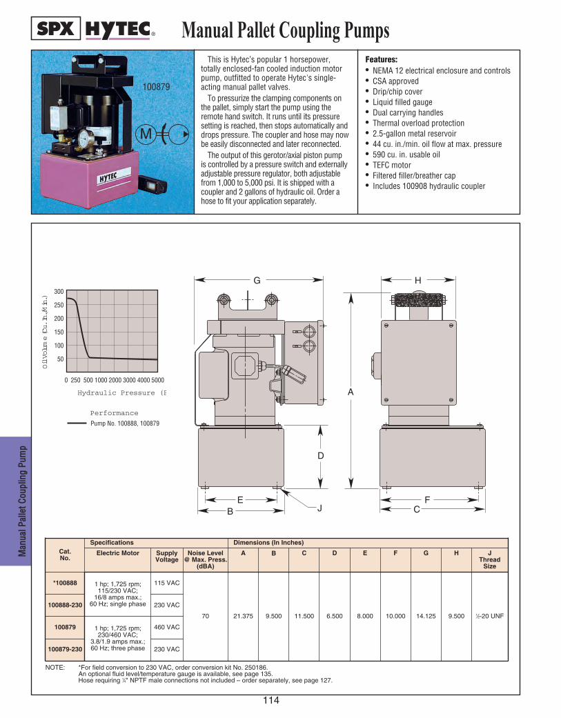
114
MMaann
uuaall PP
aallllee
tt CCoouu
pplliinn
gg PPuu
mmpp
This is Hytec’s popular 1 horsepower,totally enclosed-fan cooled induction motorpump, outfitted to operate Hytec's single-acting manual pallet valves.
To pressurize the clamping components onthe pallet, simply start the pump using theremote hand switch. It runs until its pressuresetting is reached, then stops automatically anddrops pressure. The coupler and hose may nowbe easily disconnected and later reconnected.
The output of this gerotor/axial piston pumpis controlled by a pressure switch and externallyadjustable pressure regulator, both adjustablefrom 1,000 to 5,000 psi. It is shipped with acoupler and 2 gallons of hydraulic oil. Order ahose to fit your application separately.
Features:• NEMA 12 electrical enclosure and controls• CSA approved• Drip/chip cover• Liquid filled gauge• Dual carrying handles• Thermal overload protection• 2.5-gallon metal reservoir• 44 cu. in./min. oil flow at max. pressure• 590 cu. in. usable oil• TEFC motor• Filtered filler/breather cap• Includes 100908 hydraulic coupler
Manual Pallet Coupling Pumps
M
100879
NOTE: *For field conversion to 230 VAC, order conversion kit No. 250186.An optional fluid level/temperature gauge is available, see page 135.Hose requiring 1⁄4" NPTF male connections not included – order separately, see page 127.
0 250 500 1000 2000 3000 4000 5000
300
250
200
150
100
50
Hydraulic Pressure (PSI)
Oil Volume (Cu. In./Min.)
Performance
Pump No. 100888, 100879
EB
D
J
A
G
STOP
START
FC
H
Cat.No.
Specifications Dimensions (In Inches)
Electric Motor SupplyVoltage
Noise Level@ Max. Press.
(dBA)
A B C D E F G H
*100888 1 hp; 1,725 rpm;115/230 VAC;
16/8 amps max.;60 Hz; single phase
115 VAC
70 21.375 9.500 11.500 6.500 8.000 10.000 14.125 9.500
100888-230 230 VAC
JThread
Size
1⁄2-20 UNF
100879 1 hp; 1,725 rpm;230/460 VAC;
3.8/1.9 amps max.;60 Hz; three phase
460 VAC
100879-230 230 VAC
115
MMaannuuaall PPaalllleett CCoouupplliinngg PPuumm
ppManual Pallet Coupling Pump
Very similar to Hytec’s standardelectric/hydraulic pumps, these two-stage,gerotor/axial piston pumps’ electrical circuit-ry has been redesigned specifically to beused with Hytec’s manual pallet valve.
Both pumps are equipped with a dumpvalve for automatic pressure release on thehose and coupler. This allows coupling anduncoupling under no pressure for easy, nodrip operation. Pressure range is 1,000 to5,000 psi.Features:• Enclosed induction motor• Remote hand switch with 10 ft. cord• Includes No. 100908 female coupler
• Filtered filler/breather cap• Liquid-filled gauge• Carrying handles• Pressure switch• Pressure regulator• Thermal overload protection• 5.7 gallon metal reservoir• 1⁄4” NPTF outlet• Shipped with 4 gallons of oil• Oil flow: 125 cu. in./min. at max. pressure• 1,250 cu. in. usable oil
800
700
600
500
400
300
200
100
Hydraulic Pressure (PSI)
Oil Volume (Cu. In./Min.)
Performance
Pump No. 100212Pump No. 100221
1000 3000 5000200 5000
M
100221
NOTE: Hose requiring 1⁄4" NPTF male connections not included–order separately, see page 127.†† CSA Approved.
An optional fluid level/temperature gauge is available, see page 135.
E
B
G
ON
OFF
D
A
F
C
Cat.No.
Specifications Dimensions (In Inches)
ElectricMotors
SupplyVoltage
Noise Level@ Idle/Max.
Press.(dBA)
A B C D E F GThread
Size
††100212 2 hp; 1,725 rpm;115/230 VAC;
27/14 amps max.;50/60 Hz; single phase
115 VAC74/76
25.125 14.250 15.500 7.250 12.125 13.312 1⁄2-20UNF††100212-230 230 VAC
100221 2 hp; 1,725 rpm;230/460 VAC;
6.6/3.3 amps max.;50/60 Hz; three phase
460 VAC73/78
100221-230 230 VAC

116
MMaann
uuaall PP
aallllee
tt CCoouu
pplliinn
gg PPuu
mmpp
Designed specifically for use with manualpallet valves, this single-stage pump includesa 5 ft. hose and special coupler No. 100908to mate with our manual pallet valves.
Operation is simple: connect the couplerand release the pallet valve. Change theworkpiece, then press the foot pedal to startthe pump and clamp the piece. Rocking thepedal forward releases pressure in the cou-pler while the pallet valve maintains pressureat the pallet. At this point, the coupler andhose may be disconnected.
Refer to page 89 for additional pump performance information.
Features:• Filtered filler/breather cap with dipstick• 105 cu. in. metal reservoir• 3⁄8" NPTF outlet with 1⁄4" NPTF reducer• 1⁄4" NPTF air inlet port • Shipped with hydraulic oil• Foot treadle control allows
“hands free” operation• Operating Pressure Range (nominal):
4,475 psi max. @ 125 psi air, max.1,150 psi min. @ 40 psi air, min.
• 98 cu. in. usable oil
Manual Pallet Coupling Pump100279
1000 2000 3000 4000 5000
200
150
100
50
0
Hydraulic Pressure (PSI)
Flow (Cu. In./Min.)
Performance
No. 100279125 psi Air Pressure40 psi Air Pressure
A
C
B
F D
E
RELEASE
PUMP
F I L L E R
E A T H E R
G
Cat. No.
NOTE: This pump is not for use in normal "constant pressure" applications. Requires filtered, regulated, lubricated air supply.Air requirements: 20 CFM (max.) at low hydraulic pressuredecreasing to 0 CFM when pump stalls.
Dimension (In Inches)
10.000
FEDCBA G
5.000 9.000 4.0004.2505.8757.750100279
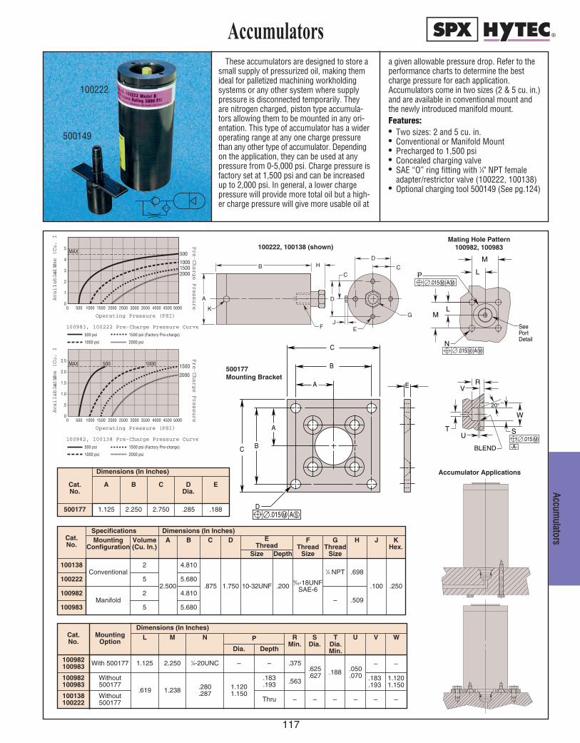
117
AAccccuummuullaattoorrss
These accumulators are designed to store asmall supply of pressurized oil, making themideal for palletized machining workholdingsystems or any other system where supplypressure is disconnected temporarily. Theyare nitrogen charged, piston type accumula-tors allowing them to be mounted in any ori-entation. This type of accumulator has a wideroperating range at any one charge pressurethan any other type of accumulator. Dependingon the application, they can be used at anypressure from 0-5,000 psi. Charge pressure isfactory set at 1,500 psi and can be increasedup to 2,000 psi. In general, a lower chargepressure will provide more total oil but a high-er charge pressure will give more usable oil at
a given allowable pressure drop. Refer to theperformance charts to determine the bestcharge pressure for each application.Accumulators come in two sizes (2 & 5 cu. in.)and are available in conventional mount andthe newly introduced manifold mount.Features:• Two sizes: 2 and 5 cu. in.• Conventional or Manifold Mount• Precharged to 1,500 psi• Concealed charging valve• SAE “O” ring fitting with 1⁄4" NPT female
adapter/restrictor valve (100222, 100138)• Optional charging tool 500149 (See pg.124)
Accumulators
100222
500149
Cat. No.
Dimensions (In Inches)
A B C DDia.
E
500177 1.125 2.250 2.750 .285 .188
Cat. No.
Dimensions (In Inches)A B C D E
ThreadF
Thread Size
GThread
Size
H J K Hex.
Size Depth
100138
2.500
4.810
.875 1.750 10-32UNF .2009⁄16-18UNF
SAE-6
1⁄4 NPT .698
.100 .250100222 5.680
100982 4.810– .509
100983 5.680
Cat. No.
MountingOption
Dimensions (In Inches)L M N P R
Min.S
Dia.U V
Dia. Depth
100982100983 With 500177 1.125 2.250 1⁄4-20UNC – – .375
.625
.627 .188 .050.070 .183
.1931.1201.150
100982100983
Without500177
.619 1.238 .280.287
1.1201.150
.183
.193
100138100222
Without500177 Thru – – – –– –
– –
Specifications
Conventional
Manifold
2
5
2
5
MountingConfiguration
Volume(Cu. In.)
-A-
RV
T
BLEND
M
N
L
M
LP
20°
S
W
U .015 M
.015 M A M
.015 M A M
See Port Detail
C
B
EA
A
BC
D .015 M A S
A
B
D
C C
D
G
E
H
F
K
J
5
4
3
2
1
0
100983, 100222 Pre-Charge Pressure Curves500 psi 1500 psi (Factory Pre-charge)
1000 psi 2000 psi
500
100015002000
MAX
50000 500 1000 1500 2000 2500 3000 3500 4000 4500
Operating Pressure (PSI)
Pre-Charge Pressure
Available V
olume (Cu. In.)
2.5
2.0
1.5
1.0
.5
0
100982, 100138 Pre-Charge Pressure Curves500 psi 1500 psi (Factory Pre-charge)
1000 psi 2000 psi
500 1000 1500
2000
MAX
50000 500 1000 1500 2000 2500 3000 3500 4000 4500
Operating Pressure (PSI)
Pre-Charge Pressure
Available V
olume (Cu. In.)
Accumulator Applications
500177 Mounting Bracket
Mating Hole Pattern100982, 100983100222, 100138 (shown)
.563
WTDia. Min.
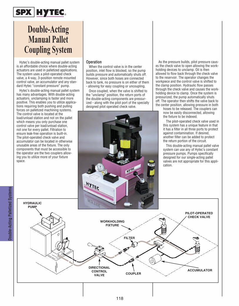
118
Hytec’s double-acting manual pallet systemis an affordable choice where double-actingactuators are used in palletized applications.The system uses a pilot-operated checkvalve, a 4-way, 3-position remote mountedcontrol valve, an accumulator and any stan-dard Hytec “constant pressure” pump.
Hytec’s double-acting manual pallet systemhas many advantages. With double-actingactuators, unclamping is faster and morepositive. This enables you to utilize applica-tions requiring both pushing and pullingforces on palletized machining systems.The control valve is located at theload/unload station and not on the palletwhich means you only purchase onecontrol valve per load/unload station,not one for every pallet. Filtration toensure leak-free operation is built-in.The pilot-operated check valve andaccumulator can be located in otherwiseunusable areas of the fixture. The onlycomponents that must be accessible tothe operator are the two couplers allow-ing you to utilize more of your fixturespace.
OOppeerraattiioonnWhen the control valve is in the center
position, inlet flow is blocked, so the pumpbuilds pressure and automatically shuts off.However, since both hoses are connectedback to tank, no pressure is on either of them- allowing for easy coupling or uncoupling.
Once coupled, when the valve is shifted tothe “unclamp” position, the return ports ofthe double-acting components are pressur-ized - along with the pilot port of the speciallydesigned pilot operated check valve.
As the pressure builds, pilot pressure caus-es the check valve to open allowing the work-holding devices to unclamp. Oil is thenallowed to flow back through the check valveto the reservoir. The operator changes theworkpiece and the control valve is shifted tothe clamp position. Hydraulic flow passesthrough the check valve and causes the work-holding device to clamp. Once the system ispressurized, the pump automatically shutsoff. The operator then shifts the valve back tothe center position, allowing pressure in both
hoses to be released. The couplers cannow be easily disconnected, allowingthe fixture to be indexed.
The pilot-operated check valve used inthis system has a unique feature in thatit has a filter in all three ports to protectagainst contamination. If desired,another filter can be added to protectthe return portion of the circuit.
This double-acting manual pallet valvesystem can use any of Hytec’s constantpressure pumps. Pumps specificallydesigned for our single-acting palletvalves are not appropriate for this appli-cation.
DDoouu
bbllee--
AAccttiinn
gg PPaa
lllleettiizz
eedd SS
yyssttee
mmss
Double-Acting Manual Pallet
Coupling System
HYDRAULICPUMP
DIRECTIONALCONTROL
VALVE
WORKHOLDINGFIXTURE
FILTER
COUPLERACCUMULATOR
PILOT-OPERATEDCHECK VALVE
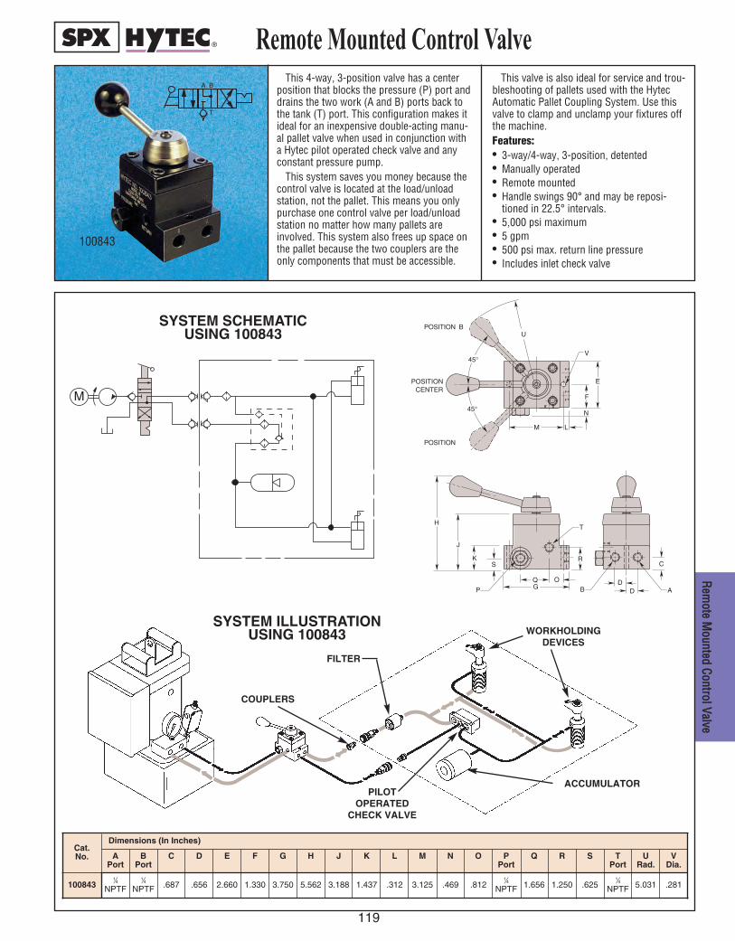
119
RReemm
oottee MMoouunntteedd CCoonnttrrooll VVaallvvee
This 4-way, 3-position valve has a centerposition that blocks the pressure (P) port anddrains the two work (A and B) ports back tothe tank (T) port. This configuration makes itideal for an inexpensive double-acting manu-al pallet valve when used in conjunction witha Hytec pilot operated check valve and anyconstant pressure pump.
This system saves you money because thecontrol valve is located at the load/unloadstation, not the pallet. This means you onlypurchase one control valve per load/unloadstation no matter how many pallets areinvolved. This system also frees up space onthe pallet because the two couplers are theonly components that must be accessible.
This valve is also ideal for service and trou-bleshooting of pallets used with the HytecAutomatic Pallet Coupling System. Use thisvalve to clamp and unclamp your fixtures offthe machine.Features:• 3-way/4-way, 3-position, detented• Manually operated• Remote mounted• Handle swings 90° and may be reposi-
tioned in 22.5° intervals.• 5,000 psi maximum• 5 gpm• 500 psi max. return line pressure• Includes inlet check valve
Remote Mounted Control ValveA B
T
100843
SYSTEM ILLUSTRATIONUSING 100843
COUPLERS
FILTER
WORKHOLDINGDEVICES
ACCUMULATORPILOT
OPERATEDCHECK VALVE
POSITION BU
M
F
E
H
J
K
G
N
L
S
Q O
P
R
DD
C
B A
T
POSITION
POSITIONCENTER
45°
45° V
M
SYSTEM SCHEMATICUSING 100843
Cat.No.
Dimensions (In Inches)
APort
BPort
C D E F G H J K L M N O PPort
Q R S TPort
URad.
VDia.
1008431⁄4
NPTF1⁄4
NPTF .687 .656 2.660 1.330 3.750 5.562 3.188 1.437 .312 3.125 .469 .8121⁄4
NPTF 1.656 1.250 .6251⁄4
NPTF 5.031 .281
120
ACCESSORIES
FFIITTTTIINNGGSS PPRREESSSSUURREE GGAAUUGGEESS
HHYYDDRRAAUULLIICC FFLLUUIIDD RROOTTAATTIINNGG UUNNIIOONNSS
HHOOSSEESS && TTUUBBIINNGG PPRREESSSSUURREE SSWWIITTCCHH
CCOOUUPPLLEERRSS RREEMMOOTTEE CCOONNTTRROOLLSS
MMAANNIIFFOOLLDDSS TTEEMMPP..//LLEEVVEELL GGAAUUGGEE
IINN--LLIINNEE FFIILLTTEERRSS RREESSEERRVVOOIIRRSS
121
FFiittttiinnggss
Cat. No. E
Tube SizeA DCB
1.0782.156 .750 .75015058 .250
.37517278 1.3912.781 .953 .750
Dimensions (In Inches)
EDCBA FThread Size
GTube Size
1.0781.859 .75015050 .438 1⁄8 NPTF .250.781
1.1092.047 .781205791 .500 1⁄4 NPTF .250.938
1.4222.484 .98410669 .625 1⁄4 NPTF .3751.062
Cat. No.
Dimensions (In Inches)
Cat. No. G
Tube Size
1.0782.156 .75015055 .438 .250.781
1.1092.219 .781205790 .500 .250.938
1.4222.844 .98410670 .625 .3751.062
FThread Size
EDCBA
1⁄8 NPTF
1⁄4 NPTF
1⁄4 NPTF
1.0781.297 .75015059
1.3591.641 .922 .281
Cat. No.
250211 .562
FTube Size
.375
EDCBA
.438 .250.219
EDBA
1.0781.297 .75015052 .781.219
1.2031.484 .875205792 1.062.281
1.3591.641 .92210665 1.094.281
1⁄8 NPTF .250
1⁄4 NPTF .250
1⁄4 NPTF .375
F
.438
.562
.562
GThread Size
HTube Size
C
Dimensions (In Inches)Cat. No.
CCrroossssCCoommpprreessssiioonn TTuubbee
4455°° MMaallee EEllbboowwCCoommpprreessssiioonn TTuubbee ttoo NNPPTTFF
MMaallee UUnniioonnCCoommpprreessssiioonn TTuubbee
UUnniioonn TTeeeeCCoommpprreessssiioonn TTuubbee
MMaallee BBrraanncchh TTeeeeCCoommpprreessssiioonn TTuubbee ttoo NNPPTTFF
9900°° MMaallee EEllbboowwCCoommpprreessssiioonn TTuubbee
9900°° MMaallee EEllbboowwCCoommpprreessssiioonn TTuubbee ttoo NNPPTTFF
Cat. No. EDCB F J
Thd. SizeH
Tube SizeGA
15053 .625.953 .672 1.359.281 .688 .562 .250 1⁄8 NPTF
1⁄4 NPTF.375.562.8751.708.281.828.7971.23410655
1.0782.156 .75015054 .250.438
1.4222.844 .984 .625
Cat.No.
10659 .375
ETube Size
DBA C
Dimensions (In Inches)
A
Dimensions (In Inches)
DTube Size
CHex.
B
.9061.562 .50015060 .250
Cat. No.
.3751.0001.875 .625250212
A
B C
B C
A
B
C B
C E
D Across Flats
E E
E
A
B C
B C
C B
E
D Across Flats
E
E
A
B C
D
C B
G E
Across Flats
G
F
A
BC
B
DGE
AcrossFlats
F
GC
A
B C
D
F E
Across Flats
F
A B C
D
G Across Flats J
A
B
E
F
C D
H
A B
C
D
MMaallee RRuunn TTeeeeCCoommpprreessssiioonn TTuubbee ttoo NNPPTTFF
Fittings
A
B C
D
H F
Across Flats
G
E
Dimensions (In Inches)
Dimensions (In Inches)
Dimensions (In Inches)
122
FFiittttii
nnggss
Fittings
TTuubbee SSlleeeevvee
CCoonnnneeccttoorr BBuusshhiinngg
MMaallee CCoonnnneeccttoorrCCoommpprreessssiioonn TTuubbee ttoo NNPPTTFF
CChheecckk VVaallvvee
.9531.281 .50015061 .250 1⁄8 NPTF
Cat. No. D
Tube SizeE
Thread SizeC
Hex.BA
205793 1.1561.484 .625 .250 1⁄4 NPTF
1.2031.641 .62510661 .375 1⁄4 NPTF
Cat. No. A
ThreadSize
206330 1⁄4 NPTF .7502.250
DHex.
BThread
Size1⁄4 NPTF
Dimensions (In Inches)
C
.500
.503.515.535*100169 .500 .844 .234
PortCat. No.
XDia.
CDia.
YBADia.
Bushing
NOTE: * Box of Ten Connector Bushings.
NOTE: Cracking pressure - 5 psi max.
Dimensions (In Inches)
A
B
D
E
C
A
A
C
D D
B
A
C B
20 °
125
125
Y
.050
.070
.015 MAX RADIUS
BLEND X
NOTE: Hytec tube sleeves may not becompatible with other tubingmaterials and grades.
PORT DETAIL
Dimensions (In Inches)
SSwwiivveell AAddaapptteerr
CCaauuttiioonn -- The female swivel end is astraight pipe thread (NPSM) with a 30°seat. All male pipe fittings that are usedwith these female swivel adapters musthave an internal 30° seat to seal properly.
RReedduucceerr NNPPTTFF
AAddaapptteerr NNPPTTFF
PPlluuggSSAAEE OO--RRiinngg
1⁄4 NPTF
BThread Size
AThread Size
Cat. No.
1.140 .750
C DHex.
15235
*252128
Dimensions (In Inches)
A Thread Size
Dimensions (In Inches)C
Hex.Cat. No.
.242
.437
.400
1⁄8 NPTF .188
.250
.312
15499
1⁄4 NPTF
3⁄8 NPTF
10479
16232
B
PLUGS - NPTF
A C
30 °
B
A
D
B
C
C
B A
D
C B
A
E
D
C
B
A
A Thread Size
Dimensions (In Inches)C D
Hex.
Cat. No.
.4507⁄16-20UNF
SAE-4.360 .188
EDia.
.563250883
B
PLUGS - SAE O-RING
1⁄8 NPTF7⁄16 20UNF
SAE-4 1.310 .6881⁄4 NPTF
* Use with 216437 Metering Valve to control flow in 1⁄4 NPTF actuators.
PPlluuggNNPPTTFF
AThread Size
Cat. No. B
Thread SizeDC
Hex.
.6251⁄8 NPTF13269 .7811⁄4 NPTF
Dimensions (In Inches)
Cat. No.
Dimensions (In Inches)
A BThread
Size
CThread
Size1⁄8 NPSM
1⁄4 NPSM1.260
1.030 1⁄4 NPTF
1⁄4 NPTF
15069
11310
Compression13031
Cat. No.
FittingStyle
10430
.250
ATube Size
.375
A

123
CCoonnnneeccttoorrNNPPTTFF
1⁄4 NPTF
Cat. No. A
Thread Size
12740 .750 .730 1.125
DDia.
CHex.
E
1⁄4 NPTF
BThread Size
CHex.
7⁄16-20UNFSAE–4216437 1⁄4 NPTF .750 .700 .435 .075
BThread Size
AThread Size
D E F
NOTE: Orifice size - .013/.017 dia.
Cat. No.
7⁄16-20 UNFSAE–4250685 1.203
BAThread Size
9⁄16-18 UNFSAE–6250686
Dimensions (In Inches)
C
.875 .562 .359 .250
DHex.
E FTube Size
1.016 .812 .391 .3751.453
JTube Size
ACat. No.
Dimensions (In Inches)
1.078
B
1.344
C D E F G HThread Size
7⁄16-20 UNFSAE–4
9⁄16-18 UNFSAE–6
250687 1.297 .219 .750 1.266 1.078 .438 .250
250688 1.625 .281 .906 1.516 1.250 .562 .375
ACat. No.
Dimensions (In Inches)
1.078
B C D E FThread Size
250689 2.156 .750 1.047 .438
GTube Size
.2507⁄16-20 UNF
SAE–4
250690
BThread Size
AThread Size
Cat. No. C D
Dimensions (In Inches)
1⁄4 NPSM 1.320 .8657⁄16-20 UNF
SAE–4
7⁄16-20 UNFSAE–4210312
BThread Size
AThread Size
Cat. No. C
Dimensions (In Inches)
1⁄4 NPTF 1.062
DHex.
E
.750 .710
7⁄16-20 UNFSAE–4250692
BThread Size
AThread Size
Cat. No. C
Dimensions (In Inches)
1⁄4 NPSM 1.120
D
.970
9900°° SSwwiivveell AAddaapptteerrCCaauuttiioonn -- The female swivel end is astraight pipe thread (NPSM) with a 30°seat. All male pipe fittings that are usedwith these female swivel adapters musthave an internal 30° seat to seal properly.
MMaallee AAddaapptteerrOO..RR..BB.. ttoo NNPPTTFF
SSwwiivveell AAddaapptteerrCCaauuttiioonn -- The female swivel end is astraight pipe thread (NPSM) with a30° seat. All male pipe fittings thatare used with these female swiveladapters must have an internal 30°seat to seal properly.
A D
E
B
C
D
E F
A
C
B
B C
A
D
E
F
G A CR OSS
FLA TS E
F
C
C D B
A
J
H
C C B B
A
G G
E A CR OSS
FLA TS D
F
C
D 30 °
A
B
B
C
A
D
E
A
C
B
30 °
D
Cat. No.
MMeetteerriinngg VVaallvveeNNPPTTFF ttoo OO..RR..BB..
MMaallee CCoonnnneeccttoorrOO..RR..BB.. ttoo CCoommpprreessssiioonn TTuubbee
9900°° MMaallee EEllbboowwCCoommpprreessssiioonn TTuubbee ttoo OO..RR..BB..
MMaallee BBrraanncchh TTeeeeCCoommpprreessssiioonn TTuubbee ttoo OO..RR..BB..
Fittings
Dimensions (In Inches)
Dimensions (In Inches)
FFiittttiinnggss
124
FFiittttii
nnggss
Fittings
AAiirr BBlleeeedd VVaallvveess
SSttrraaiigghhtt3377°° FFllaarreedd TTuubbee ttoo NNPPTTFF
AAccccuummuullaattoorr MMeetteerriinngg VVaallvveess
AAccccuummuullaattoorr CChhaarrggiinngg TTooooll
ONL Y CONCENTRIC TOOL MARKS PERMISSIBLE 125
H
G
E F 1 18 °
110048
C
B A
110049
C
B AD
B C
A
D
B C
A
D
253078
C
BA
Cat.No.
Dimensions (In Inches)
A BThread
Size
C Hex
D EDia.Max.
FThread
Size
GMin.
H
253078 1.000 5⁄16-24UNF .312–
.177 5⁄16-24UNF .350 .450.510
110048 1.630 1⁄4 NPTF .562– – – –
110049 1.4407⁄16-20UNF
SAE-4 .562 1.080
Cat. No.
Dimensions (In Inches)A B
Thd. Size
C DHex
252586 .544 —
251827 .6989⁄16-18 UNF
1⁄4 NPT.750
B
C
A
Dimension (In Inches)
Cat. A B CNo. Thread Size
500149 3.000 3.400 1⁄8 NPTF
252586
251827
C
A
(REF .) 37 °
B
1 1628 fit1
D
SSttrraaiigghhttNNPPTTFF
10672 fit2
D
C
B A
SSttrraaiigghhtt3377°° FFllaarreedd TTuubbee ttoo OO..RR..BB..
253020 fit3
B
D
C
A
(REF .) 37 °
9900°° EEllbbooww AAddaapptteerrNNPPTTFF
10617 fit4
D
C
B
A
Cat. No.
Dimensions (In Inches)A
Thd. SizeB
Thd. SizeC D
HexTube Dia.
11628 9⁄16-18 UNF 3⁄8 NPTF 1.430 .750 .375253019
7⁄16-20 UNF1⁄8 NPTF 1.220 .500
.250253076
1⁄4 NPTF1.420 .562
253174 9⁄16-18 UNF 1.430 .625 .375
Cat. No.
Dimensions (In Inches)A
Thd. SizeB
Thd SizeC D
Hex10672 1⁄4 NPTF 1⁄4 NPTF 1.450 .62511421 1⁄8 NPTF 1⁄8 NPTF 1.060 .43712328 3⁄8 NPTF 1⁄4 NPTF 1.360 .75016691 1⁄4 NPTF 1⁄8 NPTF 1.234 .593215373 1⁄8 NPTF 1⁄16 NPTF 1.010 .438
Cat. No.
Dimensions (In Inches)A
Thd. SizeB
Thd SizeC D
Hex
253020 7⁄16-20 UNF7⁄16-20 UNF
SAE-4 1.230 .562
253021 9⁄16-18 UNF9⁄16-18 UNF
SAE-6 1.300 .687
TubeDia.
.250
.375
Cat. No.
Dimensions (In Inches)
AThd. Size
BThd Size
C D
10617 1⁄4 NPTF 1⁄4 NPTF 1.090 .880
132291⁄8 NPTF
1⁄8 NPTF.780
.660
13864 1⁄4 NPTF .880
Thd.Dia.
Dia.
—
.624
.622
PORT DETAIL FOR 253078

125
FFiittttiinnggss
9900°° MMaallee EEllbbooww3377°° FFllaarreedd TTuubbee
253007 fit5
B
B
A
(REF .) 37 °
A
FFeemmaallee TTeeeeNNPPTTFF
252998 fit9
B
B B
A
A
A
9900°° MMaallee EEllbbooww3377°° FFllaarreedd TTuubbee ttoo NNPPTTFF
253009 fit6
C
D
A
(REF .) 37 °
B
MMaallee RRuunn TTeeee3377°° FFllaarreedd TTuubbee ttoo NNPPTTFF
253022 fit10
C
C D
A
A
(REF .) 37 °
B
9900°° MMaallee EEllbbooww3377°° FFllaarreedd TTuubbee ttoo OO..RR..BB..
250605 fit7
C
D
A
(REF .) 37 °
B
MMaallee BBrraanncchh TTeeee3377°° FFllaarreedd TTuubbee ttoo NNPPTTFF
253028 fit12
C
D
C
A
(REF .) 37 °
A
B
MMaallee RRuunn TTeeee3377°° FFllaarreedd TTuubbee ttoo OO..RR..BB..253024 fit1 1
C
E
C D B
(REF .) 37 °
A
A
MMaallee TTeeee3377°° FFllaarreedd TTuubbee
252996 fit8
B
B B
A
(REF .) 37 °
A
A
Cat. No.
Dimensions (In Inches)A
Thd. SizeB Tube
Dia.253007 7⁄16-20 UNF .890 .250253008 9⁄16-18 UNF 1.060 .375
Cat.No.
Dimensions (In Inches)A
Thd. SizeB
Thd. SizeC D
253009 7⁄16-20 UNF 1⁄4 NPTF 1.060 1.090253010 9⁄16-18 UNF 3⁄8 NPTF 1.140 1.220253175 7⁄16-20 UNF 1⁄8 NPTF .890 .780
TubeDia..250.375.250
Cat.No.
Dimensions (In Inches)A
Thd. SizeB
Thd. SizeC D
250605 7⁄16-20 UNF 7⁄16-20 UNF SAE-4 .890 1.030
2530119⁄16-18 UNF
9⁄16-18 UNF SAE-6 1.060 1.250
253012 3⁄4-16 UNF SAE-8 1.140 1.450
253013 7⁄8-14 UNF SAE-10 1.230 1.700
TubeDia..250
.375
EHex..562
.687
.875
1.000
Cat.No.
Dimensions (In Inches)A
Thd. SizeB Tube
Dia.252996 7⁄16-20 UNF .890 .250252997 9⁄16-18 UNF 1.060 .375
Cat. No.
Dimensions (In Inches)A
Thd. SizeB
252998 1⁄4 NPTF .890
Cat.No.
Dimensions (In Inches)A
Thd. SizeB
Thd. SizeC Tube
Dia.253022
7⁄16-20 UNF1⁄8 NPTF .890
.250253023
1⁄4 NPTF 1.060253025
9⁄16-18 UNF .375253026 3⁄8 NPTF 1.140
D
.780
1.090
1.220
Cat.No.
Dimensions (In Inches)A
Thd. SizeB
Thd. SizeC D
253024 7⁄16-20 UNF 7⁄16-20 UNF SAE-4 .890 1.030
253027 9⁄16-18 UNF 9⁄16-18 UNF SAE-6 1.060 1.250
TubeDia..250
.375
EHex..562
.687
Cat.No.
Dimensions (In Inches)A
Thd. SizeB
Thd. SizeC D
253028 7⁄16-20 UNF 1⁄8 NPTF .890 .780253030 9⁄16-18 UNF 1⁄4 NPTF 1.060 1.090
TubeDia..250.375
Fittings

126
MMaallee BBrraanncchh TTeeee3377°° FFllaarreedd TTuubbee ttoo OO..RR..BB..
253029 fit13
E
C
D
C
A
(REF .) 37 °
A
B
MMaallee CCrroossss3377°° FFllaarreedd TTuubbee
252999 fit17
B
B
B B A
A
(REF .) 37 °
A
A
MMaallee 4455°° EEllbbooww3377°° FFllaarreedd TTuubbee ttoo NNPPTTFF253014 fit14
C
D A
(REF .) 37 ° B
FFeemmaallee CCrroossssNNPPTTFF
253001 fit18
B
B
B A
B
A
A
A
MMaallee 4455°° EEllbbooww3377°° FFllaarreedd TTuubbee ttoo OO..RR..BB..
SSttrraaiigghhttBBSSPPPP ttoo OO..RR..BB..
SSttrraaiigghhttOO..RR..BB..
253015 fit15
E
C
D A
(REF .) 37 °
B NNuutt3377°° FFllaarreedd TTuubbee 253032 fit19
B
C
A
A
BD
C
D
B
C
A4455°° EEllbbooww AAddaapptteerrNNPPTTFF
19121 fit16
C
D
B
A
Cat.No.
Dimensions (In Inches)A
Thd. SizeB
Thd. SizeC D
253029 7⁄16-20 UNF 7⁄16-20 UNF SAE-4 .890 1.030
253031 9⁄16-18 UNF 9⁄16-18 UNF SAE-6 1.060 1.250
TubeDia..250
.375
EHex..562
.687
Cat.No.
Dimensions (In Inches)A
Thd. SizeB
Thd. SizeC D
253014 7⁄16-20 UNF 1⁄4 NPTF .820 .860
253016 9⁄16-18 UNF 1⁄4 NPTF .840 .860
TubeDia..250
.375
253017 9⁄16-18 UNF 3⁄8 NPTF .880 .950 .375
Cat.No.
Dimensions (In Inches)A
Thd. SizeB
Thd. SizeC D
253015 7⁄16-20 UNF 7⁄16-20 UNF SAE-4 .720 1.050
253018 9⁄16-18 UNF 9⁄16-18 UNF SAE-6 .830 1.180
TubeDia.
.250
.375
EHex.
.562
.687
Cat.No.
Dimensions (In Inches)A
Thd. SizeB
Thd. SizeC D
19121 1⁄8 NPTF 1⁄8 NPTF .470 .72010645 1⁄4 NPTF 1⁄4 NPTF .630 1.050
Cat.No.
Dimensions (In Inches)A
Thd. SizeB Tube
Dia.252999 7⁄16-20 UNF .890 .250253000 9⁄16-18 UNF 1.060 .375
Cat.No.
Dimensions (In Inches)A
Thd. SizeB
253001 1⁄4 NPTF .890
Cat.No.
Dimensions (In Inches)A
Thd. SizeB C
Hex.TubeDia.
253032 7⁄16-20 UNF .610 .562 .250253033 9⁄16-18 UNF .720 .687 .375
Cat.No.
Dimensions (In Inches)A
Thd. SizeB
Hex.D
253288 1⁄4 BSPP .750 1.250
Fittings
C
7⁄16-20 UNFSAE-4
Cat.No.
Dimensions (In Inches)A
Thd. SizeB
Thd. SizeC D
Hex.
3518167⁄16-20 UNF
SAE-45⁄16-24 UNC
SAE-2 1.065 .625
FFiittttii
nnggss

127
HHyyddrraauulliicc FFlluuiidd,, HH
oosseess && TTuubbiinngg
HHyyddrraauulliicc FFlluuiiddFor dependable performance of cylinders,
clamps, valves, and pumps, these high-gradehydraulic fluids contain anti-rust, anti-foam, andanti-sludge additives. They provide maximum filmprotection lubricity, maximum heat transfer, and awide operating temperature range.
Hytec’s “environmentally friendly” hydraulic fluidis a biodegradable, non-toxic formulation whichcan withstand severe operating conditions andprovide excellent anti-wear properties.
The “Flame-Out” fire resistant fluid has beenapproved by United States Mine Safety HealthAdministration under Referral Register Title 30, Part35. All fire resistant fluids will burn if heat source isextreme, eg.: hot slabs, molten steel, etc. They willnot, however, propagate the flame and are self-
extinguishing in the absence of an ignition source.The use of the fire resistant fluid does not
require changing the seals in any Hytec equipmentas it would when using other types of fire resistantfluids. The standard fluid need only be drainedfrom the complete system and replaced with fireresistant hydraulic fluid.TTuubbiinngg
Hytec’s low carbon steel tubing conforms to SAEJ525. Hytec fittings may not be compatible with othertubing materials and grades (eg. stainless steel). DDOONNOOTT SSUUBBSSTTIITTUUTTEE.. Hytec tubing may not be compat-ible with other fittings. DDOO NNOOTT SSUUBBSSTTIITTUUTTEE..HHoosseess
Hytec thermoplastic hose conforms to SAE100R8 specifications.
HOSES
Cat. No.
Dimensions (In Inches)A
(ft.)B
Thd. Size
CInsideDia.
DThru Dia.
EOutside
Dia.100281 1
1⁄4 NPTF .250 .141 .620
100282 2
100283 3
100285 5
100286 10
100287 15
NOTE: 4 in. min. bend radius. 5,000 psi max.
ADia.
100290
9190
.250
.375
Cat. No.
50
B(Ft.)
TUBING
Dimensions (In Inches)
.180
.245
CDia.
*NOTE: Comes in 10 5-ft. pieces. 5,000 psi max.
Hydraulic Fluid, Hoses & Tubing
HoseTubing
B
A C D 60°
A
CE
D
B
60°
9639
1002859190
HYDRAULIC FLUID
Cat.No.
Description Size Qty. Grade(ASTM)
SpecificGravity@60°F
Color(ASTM)
FlashPoint(°F)
FirePoint(°F)
Pour Point(°F)
ViscositySUS @100°F
SUS @210°F
ViscosityIndex(Min.)
FoamTest
(ASTM)
9636
Hydraulic Oil
1 Quart1
215 .875 2.0 400 430 -30 215 48 100
Pass
9636-12 12
96371 Gallon
1
9637-4 4
963821⁄2 Gal.
1
9638-2 2
9639Flame-Out fire resistant
hydraulic fluid1 Gallon
1220 .910 Light
Amber 500 550 -15 200 55 1409639-4 4
9645“Environmentally Friendly”
hydraulic fluid 1 — .922 2.0 432 — -22 183 53 213 —9646 21⁄2 Gal.

128
CCoouupp
lleerrss
Hytec offers both an economical stan-dard poppet type coupler and labor-savingpush-to-connect flat face coupler. Bothstyles are rated at 5,000 psi that has 1⁄4”NPTF connections.
The standard coupler is recommended forlower cycle applications where two handconnections and slight spillage after discon-nection is acceptable.
The push-to-connect coupler is easier toconnect and keep clean, making it ideal foruse in high cycle applications like palletcoupling. (This coupler is found on ourmanual pallet valve.) The flat face designeliminates the waste and mess associatedwith other types of hydraulic couplers. The
coupler collar is lockable, making it evenmore secure in moving applications.
FFeeaattuurreess::• Standard and push-to-connect versions• 1⁄4” NPTF connections• 5,000 psi max. operating pressures
Cat. No.
Dimensions (In Inches)
ADia.
BHex.
C D E(Coupled)
FHex.
GThread
Size
HThread
Size
JThread
Size
K LFlats
1002651.062
.750 1.1901.900
2.400.625
1⁄4 NPTF
1⁄4 NPTF
1⁄4 NPTF 1.062 .750100266 – –
100267 – – – – 1⁄4 NPTF – – –
100907 – 1.000 1.720 – – – 1⁄4 NPTF –
– – –1009081.060
– –1.790
–1.00
–1⁄4 NPTF
100909 1.000 1.720 2.970 1⁄4 NPTF
Couplers
100265
100909
Standard
D
A
100266 H
100265
F
J
K
E
C
B G
100267
L
C
100907B
G
D
E
100909
100908
H
A
F
Flexible coupler cover fitsboth male and female couplerhalves. (100907, 100908)
Coupler Cover - 251779Push-to-connect

129
MMaanniiffoollddss
The 9614 manifold assembly comes asstandard equipment on Hytec pumps No.100186, 100280, 100190, 100200, 100174,100220 and 100211. It provides the connec-tion points for pressure and return lines aswell as a gauge and/or pressure switch.These pumps are designed to have this mani-fold removed and directly replaced by ournumber 9504 pump-mounted control valve.
Use this manifold to convert these pumpsback to manifold outlet, remote mountedvalve applications. Includes manifold, reser-voir return tube, mounting hardware and two1⁄4" NPT plugs. The 100944 is available formaking SAE O-ring connections.
Manifold 36105 is ideal for connecting
multiple actuators to a single pressuresource. Used with conventional 1⁄4" NPT fit-tings, the seven ports are internally connect-ed with large diameter passages to reducerestriction. The ports on any of the four sidescan be plugged if not used. Two mountingholes are provided in the manifold to secureit to the fixture or machine tool. Since thereare no ports in the top or bottom mountingfaces, multiple manifolds can be stacked tosave space.
Manifold 100941 shares the same featuresbut provides SAE O-ring ports.
Manifolds
9614
Cat. No.
Dimension (In Inches)
A B C FD GThread Size
HThread Size
E
1009449614
10094136105
G
H J
K
O
P A
B C
D
F
E Q
B
A
G
F
C
D E
H
L
N M
96143.750 2.500 1.250 .938 1.500 .750 1⁄4 NPTF
1⁄4 NPTF
1009449⁄16-18 UNF
SAE-6
Cat. No.
Dimensions (In Inches)
A B C D E F G H J K L M NO
Thread Size(6 places)
P Dia.
Q Thread Size
36105
3.000 2.000 1.000 .375 1.000 2.000 .800 1.600 2.400 3.200 4.000 .500 1.000
1⁄4 NPTF.344
1⁄4 NPTF
7⁄16-20 UNFSAE-4
9⁄16-18 UNFSAE-6100941

130
IInn--LL
iinnee
FFiillttee
rrss
NNoo.. 110000884455 - This high pressure filter isintended for use in systems where there isflow in only one direction such as pressureor return lines between the power source andcontrol valve. This in-line filter has a remov-able/replaceable sintered bronze element.The element is accessible without removingthe filter body from the installation.
NNoo.. 110000885577,, 110000991199 - These high pres-sure, non-bypass, in-line filters are suitablefor both unidirectional and bi-directional cir-cuits. This allows the filter to be installed insingle acting or double acting circuits down-stream from the control valve where the fluidflows in both directions. It's specially rein-forced, stainless steel mesh filter element
resists fatigue from pressure spikes. Bothare ideal for use in pallet coupling circuits toprotect components from contaminantsintroduced at the couplers. The No. 100857is ideally suited for Hytec's No. 100223 man-ual pallet valve. Simply remove the couplerfrom the pallet valve and install this filterbetween the valve and coupler.
FFeeaattuurreess• 5,000 psi maximum operating pressure• Low pressure drop• Removable/replaceable elements
In-Line Filters
100845
100857
50
40
30
20
10
0
Flow (GPM)
Pressure Drop (PSI)
Performance
Filter No. 100857, 100919
Filter No. 100845
0 1 2 3
Test Fluid: Hytec Hydraulic Oil @ 100° F (215 SUS) 100857, 100919 (Shown)
C
EA
F
D
B
G
C
A
H
B
D
E G
100845
Cat. No.
Specifications Dimensions (In Inches)
FiltrationNominal/Absolute
Max.OperatingPressure
(PSI)
AInletPort
BOutletPort
CDia.
D E F GFlats
H
Hex Flats
100845 10/- Micron —
1⁄4 NPTF 1⁄4 NPTF
2.125 3.188 1.500 — 1.938 1.500 —
100857
10/25 Micron 5,000 1.380 2.100 — 1.125 — .750 1.630
1009197⁄16-20 UNF
SAE-47⁄16-20 UNF
SAE-4

Pressure Gauges
131
Hytec offers standard hydraulic pressuregauges for monitoring system pressure. All have English and metric scales for convenience.
Liquid-filled gauges are recommended forhigh cycle or pulsating applications becausethe liquid tends to dampen vibration whichprotects the meter movement and calms“needle quiver.” Dry gauges are recommend-ed for applications where fast needle reactionis essential.
All gauges have built-in snubbers. In applications where pressure spikes are present, further snubbing may be necessaryfor the dry gauge.
FFeeaattuurreess::• Dual scales• Liquid-filled or dry• 1⁄4" NPT brass connection, bottom and
1⁄8" NPT back mount
100236
100238
100878
100917
A
B
A
B
Cat.No.
Specifications
Scale Range Graduations Case
100236PSI 0-6,000 100 PSI
Liquid FilledBar 0-400 10 Bar
100238PSI 0-5,000 100 PSI
DrykPa 0-35,000 1,000 kPa
2%
1.6%
ANSIAccuracy
2.625
A
Dimensions (In Inches)
1⁄4 NPT
B
100878PSI 0-2,000 50 PSI
Liquid Filled
2.640Bar 0-140 2 Bar
100917PSI 0-6,000 1,000 PSI
1.6% 1.7701⁄8 NPT
Back MountBar 0-400 100 Bar
100236, 100238 & 100878 100917
GGaauuggeess

132
RRoott
aattiinn
gg UU
nniioonn
ss
Rotating unions allow hydraulic or airpower sources to be continuously connectedin rotating applications allowing the use ofconstant pressure hydraulic workholding onlathes, boring machines, rotary transfertables, etc. The single circuit union is usedfor single-acting systems. The dual circuitversion is necessary for double-acting sys-tems or for two separate single-acting cir-cuits. The unique design of the dual circuitunion eliminates the possibility of inter-pas-sage leakage so different fluids can be usedin each circuit without danger of intermixing.
For maximum seal life, combined condi-tions of both maximum pressure and maxi-mum rpm should be avoided.
Rotors are plated for wear and corrosionresistance. Both versions use a low torque,balanced seal design.
FFeeaattuurreess::• Single and dual circuit designs• Range 28 in. hg. to 3,000 psi max.• 250 rpm max.• Balanced seal design• Low torque
Rotating Unions
100233
100232
†Max. Press.(PSI)
Air
*100233 2 150 3,000 250 7.688 2.750 1.500 2.562 3.188 1⁄4 NPTF 1⁄4 NPTF 3⁄8 NPTF 1.375 .875 .688 1.875 1-14 UNS .250
Hyd.
†Max. Speed(RPM)
BDia.
CDia.
LFPort
(Circuit A)
DA E GPort
(Circuit B)
HPort
(Circuit A)
JHex.
KHex.
M NThread
Size(Circuit B)
ODia.
Cat. No.
Specifications Dimension (In Inches)
Circuits
NOTE: * For optimum performance, high pressure should be thru inner passage.† Operation at maximum pressure combined with maximum speed should be avoided.
†Max. Press.(PSI)
Air
100232 1 150 3,000 250 2.938 1.500 .812 3⁄8 NPTF 1⁄4 NPTF 1.812 .875
Hyd.
†Max. Speed(RPM)
BDia.
C DThread
Size
A GHex.
Cat. No.
Specifications Dimension (In Inches)
Circuits EThread
Size
F
NOTE: † Operation at maximum pressure combined with maximum speed should be avoided.
B
G
D
F
C A
E
B
J
O
N
L
M A
H
D E
F
K
G
C
100232
100233

133
PPrreessssuurree SSwwiittcchh
This hydraulic pressure switch is used toeither control or monitor system pressure.To control system pressure the switch can beelectrically wired into a pump’s power circuit.At lower pressures, the switch is closed,causing the pump to run. When the pressurereaches the switch setting, the switch con-tacts open, stopping the pump. When systemdemands cause the pressure to drop 300 psi,the contacts will again close to start thepump. This switch is included with all Hytecelectric pumps.
When used to monitor system pressure,the switch can be used to signal a warninglight or other alarm, or can be interfaced with
a machine tool to shut down a process ifpressure falls below the switch setting.
Includes 1⁄4" NPT tee for connecting tohydraulic circuit, and two feet of 18 AWG cable.
FFeeaattuurreess::• Pressure range: 1,000 to 5,000 psi• Differential: 200-600 psi, non-adjustable• Contacts are normally closed – can be
converted to normally open• Contact rating: 250 VAC max.; 5 amps max.• UL recognized• Contacts are CSA approved
9625
9625 6.000 1.828 1.938 1⁄4 NPTF .562 1.281 1.969 1⁄4 NPTF
Cat. No.
Dimension (In Inches)
AMax.
B C DThread Size
HThread Size
E F G
G
A
D
B
E
F
H
H
C
H
Pressure Switch

134
RReemm
oottee
CCoonntt
rroollss
RReemmoottee HHaanndd SSwwiittcchh NNoo.. 220022777788 Ideal for use with the 9612 control valve.
Includes 10 feet of 18 AWG 3-wire cable, and
a sealed, CSA approved, single-pole double-throw momentary rocker switch in a glassreinforced thermoplastic enclosure.
Remote Controls
202778
NNOOTTEE:: The electric solenoid remote control requires an electrical impulse toactivate or release the Booster-Pac clamp control valve. The Booster-Pac will notlose clamping pressure in the event electrical power is lost. If electric power islost while in the clamp position, pressure can be released manually.
202778
D
C
E F
A
B
Cat. No.
Dimension (In Inches)
A B E FDia.
DC
202778 7.630 2.460 1.930 .965 6.880 .315
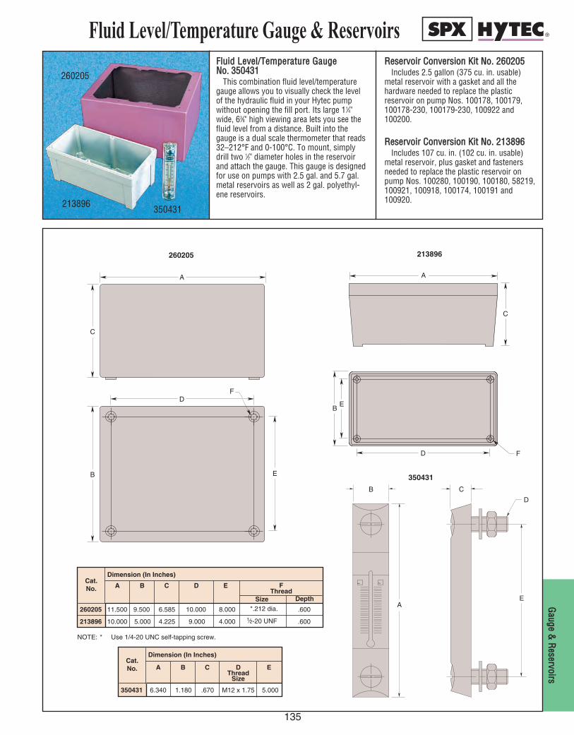
Fluid Level/Temperature Gauge & Reservoirs
135
GGaauuggee &&
RReesseerrvvooiirrss
FFlluuiidd LLeevveell//TTeemmppeerraattuurree GGaauuggee NNoo.. 335500443311
This combination fluid level/temperaturegauge allows you to visually check the levelof the hydraulic fluid in your Hytec pumpwithout opening the fill port. Its large 11⁄4"wide, 63⁄8" high viewing area lets you see thefluid level from a distance. Built into thegauge is a dual scale thermometer that reads32–212°F and 0-100°C. To mount, simplydrill two 1⁄2" diameter holes in the reservoirand attach the gauge. This gauge is designedfor use on pumps with 2.5 gal. and 5.7 gal.metal reservoirs as well as 2 gal. polyethyl-ene reservoirs.
RReesseerrvvooiirr CCoonnvveerrssiioonn KKiitt NNoo.. 226600220055Includes 2.5 gallon (375 cu. in. usable)
metal reservoir with a gasket and all thehardware needed to replace the plastic reservoir on pump Nos. 100178, 100179,100178-230, 100179-230, 100922 and100200.
RReesseerrvvooiirr CCoonnvveerrssiioonn KKiitt NNoo.. 221133889966Includes 107 cu. in. (102 cu. in. usable)
metal reservoir, plus gasket and fastenersneeded to replace the plastic reservoir onpump Nos. 100280, 100190, 100180, 58219,100921, 100918, 100174, 100191 and100920.
260205
213896350431
350431 6.340 1.180 .670 M12 x 1.75 5.000
Cat. No. A B C D
ThreadSize
E
Dimension (In Inches)
NOTE: * Use 1/4-20 UNC self-tapping screw.
213896 10.000 5.000 4.225 9.000 4.000 .600
Cat. No.
Size Depth
F Thread
A B C D E
Dimension (In Inches)
260205 11.500 9.500 6.585 10.000 8.000 .600*.212 dia.
1⁄2-20 UNF
260205
B E
D F
A
C
A
C
D
E B
F
213896
~ ~
A
B
E
D
C
350431
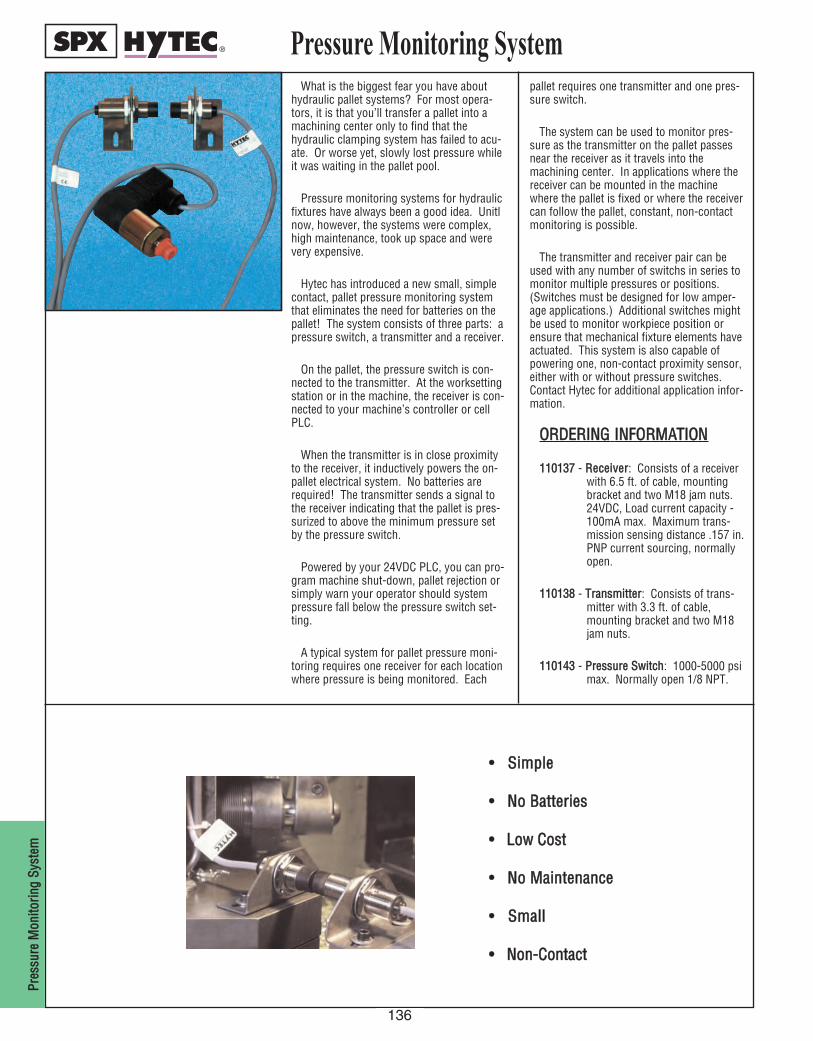
136
PPrreess
ssuurree
MMoonn
iittoorriinn
gg SSyy
sstteemm
Pressure Monitoring SystemWhat is the biggest fear you have about
hydraulic pallet systems? For most opera-tors, it is that you’ll transfer a pallet into amachining center only to find that thehydraulic clamping system has failed to acu-ate. Or worse yet, slowly lost pressure whileit was waiting in the pallet pool.
Pressure monitoring systems for hydraulicfixtures have always been a good idea. Unitlnow, however, the systems were complex,high maintenance, took up space and werevery expensive.
Hytec has introduced a new small, simplecontact, pallet pressure monitoring systemthat eliminates the need for batteries on thepallet! The system consists of three parts: apressure switch, a transmitter and a receiver.
On the pallet, the pressure switch is con-nected to the transmitter. At the worksettingstation or in the machine, the receiver is con-nected to your machine’s controller or cellPLC.
When the transmitter is in close proximityto the receiver, it inductively powers the on-pallet electrical system. No batteries arerequired! The transmitter sends a signal tothe receiver indicating that the pallet is pres-surized to above the minimum pressure setby the pressure switch.
Powered by your 24VDC PLC, you can pro-gram machine shut-down, pallet rejection orsimply warn your operator should systempressure fall below the pressure switch set-ting.
A typical system for pallet pressure moni-toring requires one receiver for each locationwhere pressure is being monitored. Each
pallet requires one transmitter and one pres-sure switch.
The system can be used to monitor pres-sure as the transmitter on the pallet passesnear the receiver as it travels into themachining center. In applications where thereceiver can be mounted in the machinewhere the pallet is fixed or where the receivercan follow the pallet, constant, non-contactmonitoring is possible.
The transmitter and receiver pair can beused with any number of switchs in series tomonitor multiple pressures or positions.(Switches must be designed for low amper-age applications.) Additional switches mightbe used to monitor workpiece position orensure that mechanical fixture elements haveactuated. This system is also capable ofpowering one, non-contact proximity sensor,either with or without pressure switches.Contact Hytec for additional application infor-mation.
OORRDDEERRIINNGG IINNFFOORRMMAATTIIOONN
111100113377 - RReecceeiivveerr: Consists of a receiver with 6.5 ft. of cable, mounting bracket and two M18 jam nuts. 24VDC, Load current capacity - 100mA max. Maximum trans-mission sensing distance .157 in.PNP current sourcing, normally open.
111100113388 - TTrraannssmmiitttteerr: Consists of trans-mitter with 3.3 ft. of cable, mounting bracket and two M18 jam nuts.
111100114433 - PPrreessssuurree SSwwiittcchh: 1000-5000 psimax. Normally open 1/8 NPT.
•• SSiimmppllee
•• NNoo BBaatttteerriieess
•• LLooww CCoosstt
•• NNoo MMaaiinntteennaannccee
•• SSmmaallll
•• NNoonn--CCoonnttaacctt
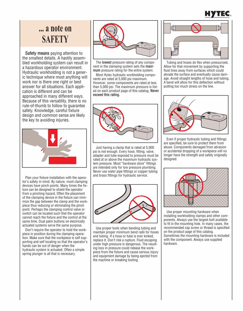
SSaaffeettyy mmeeaannss paying attention tothe smallest details. A hastily assem-bled workholding system can result ina hazardous operator environment.Hydraulic workholding is not a gener-ic technique where most anything willwork nor is there one right or bestanswer for all situations. Each appli-cation is different and can beapproached in many different ways.Because of this versatility, there is norule-of-thumb to follow to guaranteesafety. Knowledge, careful fixturedesign and common sense are likelythe key to avoiding injuries.
Plan your fixture installation with the opera-tor’s safety in mind. By nature, most clampingdevices have pinch points. Many times the fix-ture can be designed to shield the operatorfrom a pinching hazard. Often the placementof the clamping device in the fixture can mini-mize the gap between the clamp and the work-piece thus reducing or eliminating the pinchpoint. Perhaps the clamping control valve orswitch can be located such that the operatorcannot reach the fixture and the control at thesame time. Dual palm buttons on electricallyactuated systems serve the same purpose.
Don’t require the operator to hold the work-piece in position during the clamping opera-tion. Make sure that the workpiece is self sup-porting and self locating so that the operator’shands can be out of danger when thehydraulic system is actuated. Often a simplespring plunger is all that is necessary.
The lloowweesstt pressure rating of any compo-nent in the clamping system sets the mmaaxxii--mmuumm pressure rating for the entire system.
Most Hytec hydraulic workholding compo-nents are rated at 5,000 psi maximum.However, some components are rated at lessthan 5,000 psi. The maximum pressure is list-ed on each product page of this catalog. NNeevveerreexxcceeeedd tthhiiss rraattiinngg..
Just having a clamp that is rated at 5,000psi is not enough. Every hose, fitting, valve,adapter and tube exposed to pressure must berated at or above the maximum hydraulic sys-tem pressure. Most “hardware store” fittingsare intended only for low pressure plumbing.Never use water pipe fittings or copper tubingand brass fittings for hydraulic service.
Use proper tools when bending tubing andmaintain proper minimum bend radii for hosesand tubing. If a hose or tube is ever kinked,replace it. Don’t risk a rupture. Fluid escapingunder high pressure is dangerous. The result-ing loss in pressure could release the work-piece from the fixture and cause serious injuryand equipment damage by being ejected fromthe machine or breaking tooling.
Tubing and hoses do flex when pressurized.Allow for that movement by supporting thefluid lines away from surfaces which couldabrade the surface and eventually cause dam-age. Avoid straight lengths of hose and tubing.A bend will allow for this deflection withoutputting too much stress on the line.
Even if proper hydraulic tubing and fittingsare specified, be sure to protect them fromabuse. Components damaged from abrasionor accidental dropping of a workpiece will nolonger have the strength and safety originallydesigned.
Use proper mounting hardware wheninstalling workholding clamps and other com-ponents. Always use the largest bolt availableto fit in the mounting hole. In many cases, therecommended cap screw or thread is specifiedon the product page of this catalog.Sometimes the mounting hardware is includedwith the component. Always use suppliedhardware.
... a note on SAFETY
Related Documents