Product Bulletin Issue Date July 26, 2004 © 2004 Johnson Controls, Inc. 1 IFC-640 Intelligent Addressable Fire Alarm System The IFC-640 Intelligent Addressable Fire Alarm Control Panel provides a fire alarm system consisting of intelligent (analog) addressable detectors and addressable detectors and addressable modules connected to the panel on one of two Signaling Line Circuits (SLCs). As a stand-alone or small-to-large system or as a large Integrated Fire Network (IFN), the IFC-640 meets virtually every application requirement. Designed with modularity and for ease-of-system planning, you can configure the IFC-640 with just a few devices for small building applications or for a large campus or high-rise application. Simply add additional peripheral equipment to suit the application. Figure 1: IFC-640 Shown in CAB-B4 with Network Control Annunciator (JCNA) 640-Character Display Features and Benefits Distributed, Scalable System Provides a variety of options when defining a system FlashScan® Detector Technology Polls detectors and modules faster than traditional protocols with the all digital protocol Multiple Annunciation Options Provides annunciation for many different applications and various price points Autoprogramming Reduces the time and cost to program the system, accelerating installation time Code No. LIT-1201155

Welcome message from author
This document is posted to help you gain knowledge. Please leave a comment to let me know what you think about it! Share it to your friends and learn new things together.
Transcript

Product Bulletin Issue Date July 26, 2004
© 2004 Johnson Controls, Inc. 1
IFC-640 Intelligent Addressable Fire Alarm System
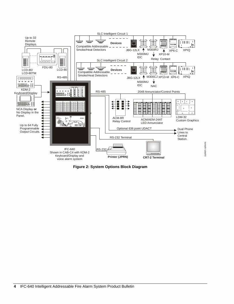
The IFC-640 Intelligent Addressable Fire Alarm Control Panel provides a fire alarm system consisting of intelligent (analog) addressable detectors and addressable detectors and addressable modules connected to the panel on one of two Signaling Line Circuits (SLCs). As a stand-alone or small-to-large system or as a large Integrated Fire Network (IFN), the IFC-640 meets virtually every application requirement. Designed with modularity and for ease-of-system planning, you can configure the IFC-640 with just a few devices for small building applications or for a large campus or high-rise application. Simply add additional peripheral equipment to suit the application.
Figure 1: IFC-640 Shown in CAB-B4 with Network Control Annunciator (JCNA) 640-Character Display
Features and Benefits
Distributed, Scalable System
Provides a variety of options when defining a system
FlashScan® Detector Technology
Polls detectors and modules faster than traditional protocols with the all digital protocol
Multiple Annunciation Options
Provides annunciation for many different applications and various price points
Autoprogramming Reduces the time and cost to program the system, accelerating installation time
Code No. LIT-1201155

FlashScan Intelligent Technology Features The following lists FlashScan intelligent technology features:
• 318 devices polled in fewer than 2 seconds
• maximum of 159 outputs activated in fewer than 2 seconds
• multicolor Light-Emitting Diodes (LEDs) blink device address during Walk Test
• fully digital, high-precision protocol (U.S. Patent 5,539,389)
• manual detector sensitivity adjustment (9 levels)
• pre-alarm Advanced Warning Addressable Combustion Sensing (AWACS®) algorithms (9 levels)
• day/night automatic sensitivity adjustment
• sensitivity windows:
- Ion: 0.5 to 2.5% per foot obscuration
- Photo: 0.5 to 2.35% per foot obscuration
- Laser (Very Intelligent Early Warning [VIEW] smoke detection): 0.03 to 1.0% per foot obscuration
- Acclimate Plus™ low-profile intelligent multi-sensor: 0.5 to 4.0% per foot obscuration
- HARSH™ Intelligent smoke detection: 0.5 to 2.35% per foot obscuration
• drift compensation (U.S. Patent 5,764,142)
• degraded mode: In the unlikely event that the JCPU-640 microprocessor fails, FlashScan detectors revert to simplified operation and can activate the JCPU-640 Notification Appliance Circuits (NACs) and alarm relay. Each circuit includes a Disable/Enable switch for this feature.
• multi-detector algorithm involves nearby detectors in alarm decision (U.S. Patent 5,627,515)
• automatic detector test (meets National Fire Protection Association [NFPA] 72)
• detector maintenance alert (two levels)
• self-optimizing pre-alarm
VIEW Smoke Detection Technology Features The following lists smoke detection technology features:
• 8 devices polled in fewer than 2 seconds revolutionary spot laser design
• AWACS algorithms that differentiate between smoke and non-smoke signals (U.S. Patent 5,831,524)
• addressable operation that pinpoints the fire location
• no moving parts to fail or filters to change • early warning performance comparable to the best
aspiration systems at a fraction of the lifetime cost
Acclimate Plus Low-Profile Intelligent Multi-sensor Features The following lists multi-sensor features:
• detector that automatically adjusts sensitivity levels without operator intervention or programming. Sensitivity increases with higher ambient temperature.
• microprocessor-based technology; combination photo and thermal technology
• FlashScan protocol or classic mode Signaling Line Circuit (SLC) communication protocol compatible with IFC-640
• freeze warning signal at 40°F (4.44°C) +/-5°F (2.77°C)
Releasing Features The following lists releasing features:
• ten independent hazards
• sophisticated cross zone (three options)
• delay timer and discharge timers (adjustable)
• abort (four options)
• low-pressure CO2 listed
2 IFC-640 Intelligent Addressable Fire Alarm System Product Bulletin
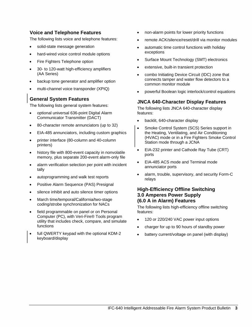
Voice and Telephone Features The following lists voice and telephone features:
• solid-state message generation
• hard-wired voice control module options
• Fire Fighters Telephone option
• 30- to 120-watt high-efficiency amplifiers (AA Series)
• backup tone generator and amplifier option
• multi-channel voice transponder (XPIQ)
General System Features The following lists general system features:
• optional universal 636-point Digital Alarm Communicator Transmitter (DACT)
• 80-character remote annunciators (up to 32)
• EIA-485 annunciators, including custom graphics
• printer interface (80-column and 40-column printers)
• history file with 800-event capacity in nonvolatile memory, plus separate 200-event alarm-only file
• alarm verification selection per point with incident tally
• autoprogramming and walk test reports
• Positive Alarm Sequence (PAS) Presignal
• silence inhibit and auto silence timer options
• March time/temporal/California/two-stage coding/strobe synchronization for NACs
• field programmable on panel or on Personal Computer (PC), with Veri-Fire® Tools program utility that includes check, compare, and simulate functions
• full QWERTY keypad with the optional KDM-2 keyboard/display
• non-alarm points for lower priority functions
• remote ACK/silence/reset/drill via monitor modules
• automatic time control functions with holiday exceptions
• Surface Mount Technology (SMT) electronics
• extensive, built-in transient protection
• combo Initiating Device Circuit (IDC) zone that connects tamper and water flow detectors to a common monitor module
• powerful Boolean logic interlock/control equations
JNCA 640-Character Display Features The following lists JNCA 640-character display features:
• backlit, 640-character display
• Smoke Control System (SCS) Series support in the Heating, Ventilating, and Air Conditioning (HVAC) mode or in a Fire Fighters Smoke Control Station mode through a JCNA
• EIA-232 printer and Cathode Ray Tube (CRT) ports
• EIA-485 ACS mode and Terminal mode annunciator ports
• alarm, trouble, supervisory, and security Form-C relays
High-Efficiency Offline Switching 3.0 Amperes Power Supply (6.0 A in Alarm) Features The following lists high-efficiency offline switching features:
• 120 or 220/240 VAC power input options
• charger for up to 90 hours of standby power
• battery current/voltage on panel (with display)
IFC-640 Intelligent Addressable Fire Alarm System Product Bulletin 3
FIRE
Relay Contact
IFC-640Shown in CAB-C4 with
andvoice alarm system
KDM-2Keyboard/Display Printer (JPRN) CRT-2 Terminal
RS-232
RS-232 Terminal
Optional 636 point UDACT Dual PhoneLines toCentralStation.
ACM-8RRelay Control ACM/AEM-24AT
LED Annunciator
LDM-32Custom Graphics
RS-485 2048 Annunciator/Control Points
JBG-12LXM300MJIDC
Devices
Devices
NAC
M300CJ XP10-M XP6-C XPIQ
JBG-12LXM300MJIDC
SLC Intelligent Circuit 2
SLC Intelligent Circuit 1
M300RJXP10-M
XP6-C XPIQ
Up to 32RemoteDisplays.
LCD-80/LCD-80TM
FDU-80LCD-80
RS-485
NCA Display No Display in thePanel.
or
Up to 64 FullyProgrammableOutput Circuits.
FIRE
Compatible AddressableSmoke/Heat Detectors
KDM-2Keyboard/Display
syst
em o
ptio
ns
Compatible AddressableSmoke/Heat Detectors
Figure 2: System Options Block Diagram
4 IFC-640 Intelligent Addressable Fire Alarm System Product Bulletin
Disable/EnableSwitches forNAC Circuit.Degraded Modebehind display.
TB1BatteryConnection(overcurrent protected)
Tb2AC PowerConnection
Tb3NAC #4
Tb4NAC #3
J8ZoneCodeInput
TB7DC Power
TB8AlarmRelay
TB9TroubleRelay
TB10SupervisoryRelay
TB11SecurityRelay
TB12EIA-485TerminalMode(supervised)
TB13EIA-485ACSMode
TB14EIA-232Printer
Tb15EIA-232CRT-2
TB16SLC #1Connections(detectors,modules,supervised)
JCPU
-640
NAC LEDs(Tb5, 4, 3 also)
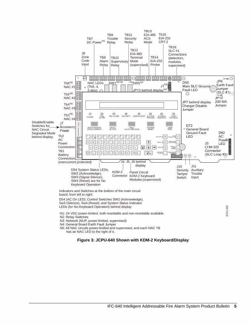
N1: 24 VDC power-limited, both resettable and non-resettable available.N2: Relay SwitchesN3: Network (NUP, power-limited, supervised)N4: General Board Earth Fault JumperN5: All NAC circuits power-limited and supervised, and each NAC TB has an NAC LED to the right of it.
J10SecurityTamperSwitch
J11AuxiliaryTroubleInput
KDM-2 Connector
Panel CircuitKDM-2 KeyboardModules,(supervised)
Tb5NAC #2
Tb6NAC #1
D54 (AC On LED); Control Switches SW2 (Acknowledge),Sw3 (Silence), Sw4 (Reset); and System Status IndicatorLEDs (for No-Keyboard Operation) behind display
J4, J5, J6 behind display
N1
N2 N2N3
N4
N5
N5
N5
N5
Indicators and Switches at the bottom of the main circuitboard, from left to right:
D54 System Status LEDs,SW2 (Acknowledge),SW3 (Signal Silence),SW4 (Reset) are for No Keyboard Operation
Figure 3: JCPU-640 Shown with KDM-2 Keyboard/Display
IFC-640 Intelligent Addressable Fire Alarm System Product Bulletin 5
SpeakerPhones
24 V
IFC-640
IFC-640JPRNACS
LCD-80
IFWJPRN
JPRN
JNCA
Annunciator Control System (ACS)
OptionalStyle 7Connection
SpeakerPhones
IFW
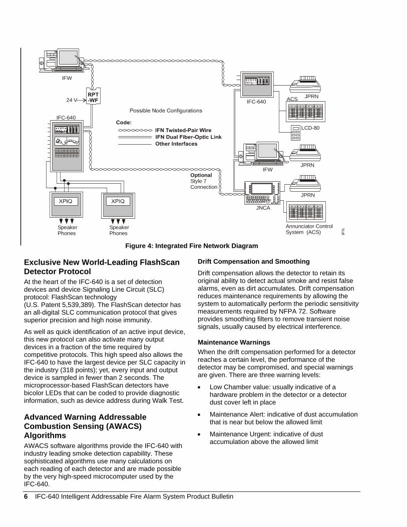
Figure 4: Integrated Fire Network Diagram
Exclusive New World-Leading FlashScan Detector Protocol At the heart of the IFC-640 is a set of detection devices and device Signaling Line Circuit (SLC) protocol: FlashScan technology (U.S. Patent 5,539,389). The FlashScan detector has an all-digital SLC communication protocol that gives superior precision and high noise immunity.
As well as quick identification of an active input device, this new protocol can also activate many output devices in a fraction of the time required by competitive protocols. This high speed also allows the IFC-640 to have the largest device per SLC capacity in the industry (318 points); yet, every input and output device is sampled in fewer than 2 seconds. The microprocessor-based FlashScan detectors have bicolor LEDs that can be coded to provide diagnostic information, such as device address during Walk Test.
Advanced Warning Addressable Combustion Sensing (AWACS) Algorithms AWACS software algorithms provide the IFC-640 with industry leading smoke detection capability. These sophisticated algorithms use many calculations on each reading of each detector and are made possible by the very high-speed microcomputer used by the IFC-640.
Drift Compensation and Smoothing Drift compensation allows the detector to retain its original ability to detect actual smoke and resist false alarms, even as dirt accumulates. Drift compensation reduces maintenance requirements by allowing the system to automatically perform the periodic sensitivity measurements required by NFPA 72. Software provides smoothing filters to remove transient noise signals, usually caused by electrical interference.
Maintenance Warnings When the drift compensation performed for a detector reaches a certain level, the performance of the detector may be compromised, and special warnings are given. There are three warning levels:
• Low Chamber value: usually indicative of a hardware problem in the detector or a detector dust cover left in place
• Maintenance Alert: indicative of dust accumulation that is near but below the allowed limit
• Maintenance Urgent: indicative of dust accumulation above the allowed limit
6 IFC-640 Intelligent Addressable Fire Alarm System Product Bulletin
Sensitivity Adjust Nine sensitivity levels are provided for alarm detection. These levels can be set manually or can be programmed to change automatically between day and night. Nine levels of pre-alarm sensitivity also can be selected, based on predetermined levels of measured fire threat. Pre-alarm operation can be latching or self-restoring and can be used to activate special control functions.
Self-Optimizing Pre-alarm Each detector may be set for Self-Optimizing pre-alarm. In this special mode, the detector learns its normal environment, measures the peak analog readings over a long period of time, and sets the pre-alarm level just above these normal peaks.
Cooperating Multi-detector Sensing A patented feature of AWACS algorithms is the ability of a smoke sensor to consider readings from nearby sensors in making alarm or pre-alarm decisions. Without statistical sacrifice in the ability to resist false alarms, it allows a sensor to increase its sensitivity to actual smoke by a factor of almost two to one.
Field Programming Options Autoprogram Autoprogram is a timesaving feature of the IFC-640 that allows for the easy addition of new devices. It is a special software routine that allows the IFC-640 to learn which devices are physically connected and automatically loads them in the program with default values for all parameters. Requiring fewer than 40 seconds to run, this routine provides the user almost immediate fire protection in a new installation, even if only a portion of the detectors is installed.
Keypad Program Edit (with KDM-2) The IFC-640 has the exclusive feature of full program creation and edit capability from the front panel keypad, while continuing to provide fire protection. The architecture of the IFC-640 software is such that each point entry carries its own program, including control-by-event interlocking links to other points. This allows the program to be entered with independent per-point segments, while the IFC-640 simultaneously monitors other (already installed) points for alarm conditions.
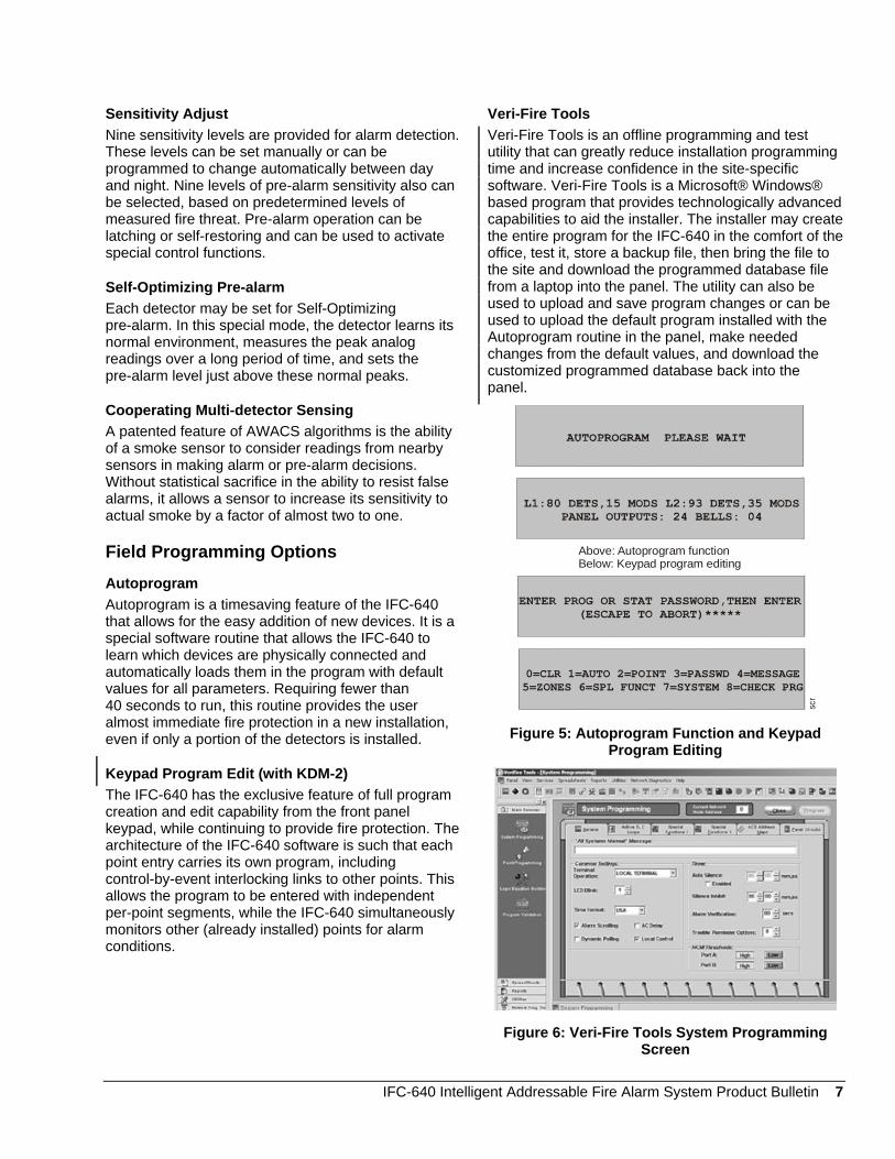
Veri-Fire Tools Veri-Fire Tools is an offline programming and test utility that can greatly reduce installation programming time and increase confidence in the site-specific software. Veri-Fire Tools is a Microsoft® Windows® based program that provides technologically advanced capabilities to aid the installer. The installer may create the entire program for the IFC-640 in the comfort of the office, test it, store a backup file, then bring the file to the site and download the programmed database file from a laptop into the panel. The utility can also be used to upload and save program changes or can be used to upload the default program installed with the Autoprogram routine in the panel, make needed changes from the default values, and download the customized programmed database back into the panel.
0=CLR 1=AUTO 2=POINT 3=PASSWD 4=MESSAGE5=ZONES 6=SPL FUNCT 7=SYSTEM 8=CHECK PRG
Above: Autoprogram functionBelow: Keypad program editing
scr
Figure 5: Autoprogram Function and Keypad Program Editing
Figure 6: Veri-Fire Tools System Programming Screen
IFC-640 Intelligent Addressable Fire Alarm System Product Bulletin 7
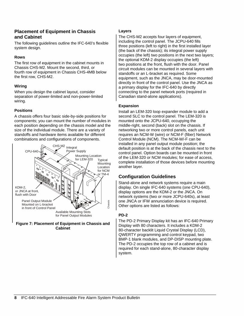
Placement of Equipment in Chassis and Cabinet The following guidelines outline the IFC-640’s flexible system design.
Rows The first row of equipment in the cabinet mounts in Chassis CHS-M2. Mount the second, third, or fourth row of equipment in Chassis CHS-4MB below the first row, CHS-M2.
Wiring When you design the cabinet layout, consider separation of power-limited and non-power-limited wiring.
Positions A chassis offers four basic side-by-side positions for components; you can mount the number of modules in each position depending on the chassis model and the size of the individual module. There are a variety of standoffs and hardware items available for different combinations and configurations of components.
CPU-640
CHS-M2 IntegralPower Supply
Mounting Locationfor LEM-320 Typical
MountingLocationfor NCMor TM-4
Available Mounting Slotsfor Panel Output Modules
KDM-2,or JNCA at front,flush with Door
Panel Output ModuleMounted on L-bracketin front of Control Panel C
hass
is
Figure 7: Placement of Equipment in Chassis and Cabinet
Layers The CHS-M2 accepts four layers of equipment, including the control panel. The JCPU-640 fills three positions (left to right) in the first installed layer (the back of the chassis); its integral power supply occupies (the left) two positions in the next two layers; the optional KDM-2 display occupies (the left) two positions at the front, flush with the door. Panel circuit modules can be mounted in several layers with standoffs or an L-bracket as required. Some equipment, such as the JNCA, may be door-mounted directly in front of the control panel. Use the JNCA as a primary display for the IFC-640 by directly connecting to the panel network ports (required in Canadian stand-alone applications).
Expansion Install an LEM-320 loop expander module to add a second SLC to the control panel. The LEM-320 is mounted onto the JCPU-640, occupying the middle-right, second (back) slot on the chassis. If networking two or more control panels, each unit requires an NCM-W (wire) or NCM-F (fiber) Network Control Module (NCM). The NCM-W/-F can be installed in any panel output module position; the default position is at the back of the chassis next to the control panel. Option boards can be mounted in front of the LEM-320 or NCM modules; for ease of access, complete installation of those devices before mounting another layer.
Configuration Guidelines Stand-alone and network systems require a main display. On single IFC-640 systems (one CPU-640), display options are the KDM-2 or the JNCA. On network systems (two or more JCPU-640s), at least one JNCA or IFW annunciation device is required. Other options are listed as follows:
PD-2 The PD-2 Primary Display kit has an IFC-640 Primary Display with 80 characters. It includes a KDM-2 80-character backlit Liquid Crystal Display (LCD), QWERTY programming and control keypad, two BMP-1 blank modules, and DP-DISP mounting plate. The PD-2 occupies the top row of a cabinet and is required for each stand-alone, 80-character display system.
8 IFC-640 Intelligent Addressable Fire Alarm System Product Bulletin
JNCA The Network Control Annunciator (JNCA) has an LCD display capable of 640 characters, dedicated function keys, soft-keys associated with selections displayed on the 640-character display, and a QWERT keyboard. On single IFC-640 systems, the JNCA can be the Primary Display for the panel and connects directly to the JCPU-640, if used in place of a KMD-2. On Network systems (two or more IFC-640s), one network display (either JNCA or IFW) is required for every system. On network systems, the JNCA connects to (and requires) a Network Communications Module (NCM-W/F). The JNCA mounts in a row of Fire Alarm Control Panel (FACP) nodes or in two annunciator positions. Mounting options include the DP-DISP, ADP-4B, or in an annunciator box, such as the ABS-2D. In CAB-4 top row applications, a DP-DISP and two BMP-1 blank modules are required for mounting.
JCPU-640 The JCPU-640 is a Central Processing Unit (CPU) with integral 120 VAC, 3.0 amperes (6.0 amperes in alarm) output power supply for an IFC-640 system. The JCPU-640 includes the CPU; one SLC expandable to two; installation, programming and operating manuals. Order one JCPU-640 per system or as necessary (up to 103 network nodes) on a network system.
JCPU-640E The JCPU-640E is the same as JCPU-640 but requires 220 VAC with 1.5 amperes input.
CHS-M2 The CHS-M2 is a mounting chassis for the JCPU-640. One chassis is required for each JCPU-640(E).
Panel Circuit Modules The IFC-640 includes the ability to communicate with up to eight conventional control modules, each with up to eight IDC or NAC circuits. Any mix of notification, relay, speaker, or telephone may be used. Choose any combination of up to eight output modules: ICM/ICE, CRM/CRE, DCM-4 or VCM/VCE. Panel Circuit Modules mount on either the two far-right positions of the DP-DISP (next to the primary display) or on any of the four positions on the CHS-4N chassis (CHS-4MN kit required).
CHS-4MB The CHS-4MB is an expansion chassis that mounts up to four modules. It includes the CHS-4N, MP-1B (Module Dress Panel) and expander ribbon cable.
ICM-4RK The ICM-4RK is a notification appliance circuit module that provides four Class B (Style Y) or Class A (Style Z) alarm Notification Appliance Circuits (includes auxiliary power harness, End-of-Line Resistors [EOLRs], and slide-in labels). The module includes ON/OFF controls and ON/OFF LEDs. The maximum signaling current is 3.0 amperes per circuit or 6.0 amperes per module, subject to power supply limitations.
ICE-4 The ICE-4 is a notification appliance circuit expander that expands the ICM-4 to provide a total of eight Class B (Style Y) or Class A (Style Z) alarm Notification Appliance Circuits. The circuit ratings are the same as ICM-4RK. Note that there is a maximum of one per ICM-4RK. The expander may also be used to add four Notification Appliance Circuits to VCM-4.
CRM-4RK The CRM-4RK is a control relay module that has four Form-C relay contacts rated at 5.0 amperes, 120 VAC or 28 VDC (resistive) per circuit. The module includes manual ON/OFF controls and LEDs.
CRE-4 The CRE-4 is a control relay expander that expands the CRM-4RK to provide a total of eight Form-C relay contacts. Note that there is a maximum of one expander per CRM-4RK. The expander may also be connected to add four relays to ICM-4, TCM-2, TCM-4, or VCM-4.
VCM-4RK The VCM-4RK is a voice control module that provides four Class B (Style Y, 25 and 70 VRMS) and Class A (Style Z, 25 VRMS only) speaker circuits, eight manual select switches and indicators, slide-in labels, and plug-in terminal blocks. Move jumper to convert to telephone circuits with remote ring signal and local call-in flash. The module may be expanded to eight circuits with VCE-4, ICE-4, or CRE-4.
VCE-4 The VCE-4 is a voice control expander that adds four circuits to VCM-4RK. Note that the VCM-4RK/VCE-4 combination must be eight speaker or eight phone circuits.
DCM-4RK The DCM-4RK is a nonexpandable, dual-channel module that provides four Class B (Style Y, 25 and 70 VRMS) or Class A (Style Z, 25 VRMS only) speaker circuits plus four channel A/B select relays.
IFC-640 Intelligent Addressable Fire Alarm System Product Bulletin 9
Other Option Modules ARM-4 The ARM-4 is an auxiliary relay module with four Form-C (DPDT) relays controlled by a relay module (CRM-4RK or CRE-4). Normally Open (N.O.) contacts are rated 20 amperes and Normally Closed (N.C.) contacts are rated 10 amperes at 125 VAC and 30 VDC. Note that there is a maximum of one ARM-4 for each CRM-4RK or CRE-4.
JVCC-1B The JVCC-1B is a voice control center that provides a variety of user-selectable tones on a single channel. Up to four different tones or messages may be selected on the channel. The VCC-1B provides optional digital voice message capability and on-site programmable voice messages using the Audio Message Generator (AMG-1) microphone, cables, dress panels, and instructions, which are included.
JVTCC-1B The JVTCC-1B is a voice/telephone control center that provides all the components that the VCC-1B provides, plus two-way Fire Fighters Telephone (FFT-7) capability.
JTCC-1B The TCC-1B is a telephone control center that provides a stand-alone, two-way Fire Fighters Telephone (FFT-7S) and includes cables, dress panel, and instructions.
AMG-1 and AMG-1E The AMG-1 and AMG-1E are audio message generators (without microphone) that should be ordered in addition to the VCC-1 or VTCC-1 if a two-channel system is required.
FFT-7/FFT-7S The FFT-7/FFT-7S is the Fire Fighters Telephone control with master handset.
AA-30 The AA-30 is an audio amplifier that has 30 watts and switch-mode power. It includes amplifier and audio input supervision, backup input, and automatic switchover, power supply, and cables.
AA-120/AA-100 The AA-120 is an audio amplifier that provides up to 120 watts of 25 VRMS audio power for the IFC-640. The amplifier contains an integral chassis for mounting to a CAB-B4, -C4, or -D4 backbox (consumes one row). It also includes switch-mode power, audio input and amplified output supervision, backup input, and automatic switchover to backup tone. Order the AA-100 for 70.7 VRMS systems and 100 watts of power.
VROM-(n) The VROM-(n) is a factory programmed digital message for installation in the AMG-1 or AMG-1E, which provides up to 24 seconds of evacuation message on a nonvolatile memory chip. Choose one of many standard messages available. Up to two of these messages may be installed in one AMG. Includes VROM, instructions for installation and operation, and written text of message.
VRAM-1 The VRAM-1 is field-programmed memory to be installed in AMG-1E, which provides up to 24 seconds of field-programmable evacuation message on a nonvolatile memory chip. Message is programmed from microphone or cassette tape. Up to two of these nonvolatile memory chips may be installed in one AMG. Includes VRAM and instructions for installation and operation.
APS-6R The APS-6R is an auxiliary power supply (expander) that provides up to 6.0 amperes of regulated power for compatible Notification Appliance Circuits. The expander includes battery input and transfer relay and overcurrent protection, which mounts on one of four positions on a CHS-4L or CHS-4 chassis.
ACPS-2406 The ACPS-2406 has a 6-ampere addressable charger power supply.
FCPS-24 The FCPS-24 is a remote 6-ampere (4-ampere continuous) repeater/power supply.
UZC-256 The UZC-256 is a programmable universal zone coder that provides positive, noninterfering, successive zone coding. The coder is microprocessor controlled, field programmable from IBM® compatible computers (requires optional programming kit).
10 IFC-640 Intelligent Addressable Fire Alarm System Product Bulletin

LCD-80/LCD-80TM/FDU-80 The LCD-80/LCD-80TM/FDU-80 is an 80-character, backlit LCD display that mounts up to 1828.8 m (6,000 ft) from the panel when operating in terminal mode. There can be up to 32 per IFC-640.
ACS The ACS includes the following Annunciator Control Modules (ACM): ACM-16AT, AEM-16AT, ACM-24AT, AEM-24AT, ACM-32A, AEM-32A, ACM-48, and AEM-48.
AFM The Annunciator Fixed Modules (AFMs) include the FM-16A, AFM-16AT, and AFM-32A.
LDM The Lamp Driver Modules (LDMs) include the LDM-32, LDM-E32, and LDM-R32.
ACM-8R The ACM-8R is a remote relay module with eight Form-C contacts that can be located up to 1828.8 m (6,000 ft) from the panel on four wires.
SCS The SCS is a smoke control station with 8 (expandable to 16) circuits for smoke control applications.
RPT-485 The RPT-485 repeats EIA-485 over twisted pair or converts to fiber-optic medium.
XP6 The XP6-C, XP6-R, XP6-MA, and XP10-M provide FlashScan transponder points.
XP The XP Series Transponder provides conventional monitor and control points (Classic Loop Interface Protocol [CLIP] mode only).
XPIQ The XPIQ Quad Intelligent Voice Transponder for distributed multi-channel voice evacuation systems has an integrated audio amplification and distribution subsystem controlled by FACP. It is capable of playing up to four simultaneous messages and accepts up to four 25-watt 25 VRMS amplifiers.
CHS-4 The CHS-4 is a chassis for mounting up to four APS-6R or other function modules.
CHS-4L The CHS-4L is a low profile, four-position chassis, which mounts two AA-30 amplifiers or one AMG-E and one AA-30 or other function modules.
DP-1B The DP-1B is a blank dress panel that provides a dead-front panel for unused tiers or covers AA-30, AA-120, or AMG-E.
CAB-4 Series The CAB-4 Series cabinets are fabricated from 16-gauge steel, with a unique full-front LEXAN® covering, and are reverse-silk-screened for durability. The cabinet assembly consists of two basic parts: a backbox (SBB-_4) and a locking door (DR-_4) that may hinge right or left. Cabinets are available in four sizes, A through D, with one to four tiers.
Agency Listings and Approvals See the Technical Specifications section for listing agencies and file numbers. These listings and approvals apply to the basic IFC-640 control panel. Certain modules may not be listed by certain approval agencies, or listing may be in process. Consult the factory for latest listing status.
The IFC-640 complies with UL Standards 864 UOJZ (Fire) and 1076 (Burglary) and is designed to meet NFPA 72 Local, Auxiliary, Remote Station, Proprietary, and Emergency Voice/Alarm Fire System requirements.
System Capacity The details of the system capacity are as follows:
• Intelligent Signaling Line Circuits (SLCs): 1 expandable to 2
• Intelligent detectors: 159 per SLC • Addressable monitor/control modules:
159 per SLC • Programmable internal hardware and output
circuits (4 NAC standard): expandable to 68 • Programmable software zones: 99 • Special programming zones: 14 • LCD annunciators per JCPU-640 and JNCA
(observe power): 32 • ACS annunciators per JCPU-640: 32 address x
64 points • ACS annunciators per JNCA: 32 address x 64 or
96 points Note: The JNCA supports up to 96 annunciator address points per ACM-24/48 with expander modules.
IFC-640 Intelligent Addressable Fire Alarm System Product Bulletin 11

Product Line Information Table 1: KDM-2 Keyboard/Display Controls and Indicators Product Description Program Keypad QWERTY type (keypad layout) 8 LED Indicators AC Power, Fire Alarm, Pre-Alarm, Security Alarm, Supervisory Signal, System
Trouble, Disabled Points, Alarm Silenced Membrane Switch Controls Acknowledge/Step, Signal Silence, Evacuate, System Reset, Lamp Test LCD Display 80 characters (2 x 40) with long-life LED Backlight
Table 2: Compatible Devices, EIA-232 Ports Product Description JPRN-5 80-column Printer VS4095/S2 Printer, 40-column, 24 V; Mounted in external backbox. (Order from Keltron, Inc.) CRT-2 Video Display Terminal
Table 3: Accessories Product Description LEM-320 Loop Expander Module; Expands each IFC-640 to two SLCs. TM-4 Transmitter Module includes three reverse-polarity circuits and one municipal box
circuit and mounts in panel module position (FC-2000 style) or in CHS-M2 position. KDM-2 80-character display and QWERTY Programming Keypad included. Order for PD-2
replacement or to use as a servicing/programming tool for displayless IFC-640 nodes. NCM-W Network Communications Module, Wire. Order one NCM per network node
(JCPU-640 or JNCA). NCM-F Network Communications Module, Fiber; Order one NCM per network node
(JCPU-640 or JNCA). IFW-W Intelligent Fire Workstation (IFW), UL Listed graphics PC with 19 in. display and
mouse. Each NCS consumes 1 of 103 network addresses. IFW-F Intelligent Fire Workstation (IFW), Fiber. UL Listed graphics PC with 19 in. display and
mouse. Each NCS consumes 1 of 103 network addresses. JVeri-Fire-TCD Veri-Fire Tools CD-ROM. Contains programming software for the IFC-640, IFC-3030,
JNCA, and XPIQ. Includes local panel connection cable. Programming PC requires a serial port connection.
ACM-24AT ACS annunciator with up to 96 points of annunciation with Alarm or Active LED, Trouble LED, and switch per circuit. Active/Alarm LEDs can be programmed (by turning on switch selection) by point to be red, green, or yellow. The Trouble LED is always yellow.
AEM-24AT Same LED and switch capabilities as ACM-24AT. Expands the ACM-24AT to 48, 72, or 96 points.
ACM-48A ACS annunciator with up to 96 points of annunciation with Alarm or Active LED per circuit. Active/Alarm LEDs can be programmed (by turning on switch selection) in groups of 24 to be red, green, or yellow. Expandable to 96 points with one AEM-48A.
AEM-48A Same LED capabilities as ACM-48A. Expands the ACM-48A to 96 points. PS Series IFC-640 uses two 12-volt, 12 to 55 Ampere Hour (AH) batteries. JCI-LBB Battery Box (required for batteries over 25 AH).
12 IFC-640 Intelligent Addressable Fire Alarm System Product Bulletin
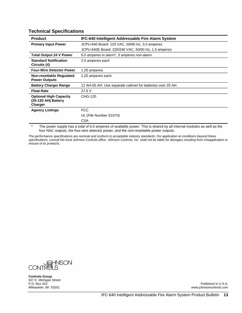
Technical Specifications Product IFC-640 Intelligent Addressable Fire Alarm System Primary Input Power JCPU-640 Board: 120 VAC, 50/60 Hz, 3.0 amperes
JCPU-640E Board: 220/240 VAC, 50/60 Hz, 1.5 amperes Total Output 24 V Power 6.0 amperes in alarm*, 3 amperes non-alarm Standard Notification Circuits (4)
2.5 amperes each
Four-Wire Detector Power 1.25 amperes Non-resettable Regulated Power Outputs
1.25 amperes each
Battery Charger Range 12 AH-55 AH. Use separate cabinet for batteries over 25 AH. Float Rate 27.6 V Optional High Capacity (25-120 AH) Battery Charger
CHG-120
Agency Listings FCC UL (File Number S1570) CSA
* The power supply has a total of 6.0 amperes of available power. This is shared by all internal modules as well as the four NAC outputs, the four-wire detector power, and the non-resettable power outputs.
The performance specifications are nominal and conform to acceptable industry standards. For application at conditions beyond these specifications, consult the local Johnson Controls office. Johnson Controls, Inc. shall not be liable for damages resulting from misapplication or misuse of its products.
Controls Group 507 E. Michigan Street P.O. Box 423 Published in U.S.A.Milwaukee, WI 53201 www.johnsoncontrols.com
IFC-640 Intelligent Addressable Fire Alarm System Product Bulletin 13
Related Documents