Citation for published version: Harris, R, Gusinde, B & Roynon, J 2012, 'Design and construction of the pods sports academy, Scunthorpe, England', Paper presented at World Conference of Timber Engineering 2012, Auckland, New Zealand, 16/07/12 - 19/07/12 pp. 510-517. Publication date: 2012 Document Version Peer reviewed version Link to publication University of Bath Alternative formats If you require this document in an alternative format, please contact: [email protected] General rights Copyright and moral rights for the publications made accessible in the public portal are retained by the authors and/or other copyright owners and it is a condition of accessing publications that users recognise and abide by the legal requirements associated with these rights. Take down policy If you believe that this document breaches copyright please contact us providing details, and we will remove access to the work immediately and investigate your claim. Download date: 04. Oct. 2021

Welcome message from author
This document is posted to help you gain knowledge. Please leave a comment to let me know what you think about it! Share it to your friends and learn new things together.
Transcript

Citation for published version:Harris, R, Gusinde, B & Roynon, J 2012, 'Design and construction of the pods sports academy, Scunthorpe,England', Paper presented at World Conference of Timber Engineering 2012, Auckland, New Zealand, 16/07/12- 19/07/12 pp. 510-517.
Publication date:2012
Document VersionPeer reviewed version
Link to publication
University of Bath
Alternative formatsIf you require this document in an alternative format, please contact:[email protected]
General rightsCopyright and moral rights for the publications made accessible in the public portal are retained by the authors and/or other copyright ownersand it is a condition of accessing publications that users recognise and abide by the legal requirements associated with these rights.
Take down policyIf you believe that this document breaches copyright please contact us providing details, and we will remove access to the work immediatelyand investigate your claim.
Download date: 04. Oct. 2021

Prepared for and presented at the World Conference of Timber Engineering 2012 – Auckland, New Zealand
DESIGN AND CONSTRUCTION OF THE PODS SPORTS ACADEMY, SCUNTHORPE, ENGLAND Richard Harris 1, Bernd Gusinde2 , Jonathan Roynon3
ABSTRACT: The design commissioned for The Pods Sports Academy in Scunthorpe was won in an open competition in 2007. It is a series of unified spaces enclosed within an envelope of undulating domes. Structural challenges included complex formfinding, design of the interfaces between spaces, nodal connection design for fast, safe construction and cladding. The project opened to the public in July 2011.
KEYWORDS: Timber Shells, Swimming Pool, Formfinding, Glulam
1 INTRODUCTION The project consists of a five linked shells, each of which is optimized for the space it covers. A competition amongst local school children led to the building being named “The Pods”. In order of decreasing size, the shells cover: • Six badminton-court dry sports hall –
approx. 65 metres span (65 metres across the diagonal)
• 25m 8-lane swimming pool - approx. 35 metres span
• Training pool - approx. 20 metres span • Gym and dance studio - approx. 25 metres
span • Café and crèche - approx. 15 metres span
Form-finding and Engineering, by Buro Happold, uses a process of optimization, which combines both advanced computing methods and creative design judgment. Design and detailing is aimed at pre-fabrication and fast, high quality construction. The main structural components are glued-laminated (glulam) timber. Jointing at the steel nodes uses bonded rods with sockets and bolts. 1 Richard Harris, The University of Bath, BRE Centre for Innovative Construction Materials, Department of Architecture and Civil Engineering, Bath, BA2 7AY, England. Email: [email protected] 2 Bernd Gusinde, Engineer, Mayr-Melnhof Kaufmann Reuthe GmbH, Vorderreuthe 57, Reuthe, Austria. [email protected] 3 Jonathan Roynon, Associate Director, Buro Happold, Camden Mill, Lower Bristol Road, Bath, BA2 3DQ. England. Email: [email protected]
2 DESIGN CONCEPT The two largest domes of the Sports Academy house a multi-purpose dry sports area, including competition-level badminton courts and an eight-lane competition pool with spectator areas. Figures 1 and 2 show the layout of spaces. The specification included additional public areas; dressing rooms and washrooms, sauna and spa area, a cafe and a crèche as well as several meeting and function rooms and offices.
Figure 1: Ground Floor Plan with use zones (Andrew Wright Architects)
Prepared for and presented at the World Conference of Timber Engineering 2012 – Auckland, New Zealand
Figure 2: First Floor Plan with use zones (Andrew Wright Architects)
2.1 ARCHITECTURAL DESIGN Both concept and scheme design stages went through a number of iterations, with interactive collaboration between the architect and the engineer, as well as discussion with experienced contractors. Through this process, a structural layout for aesthetic architectural requirements, practical constraints in use and construction feasibility was developed. The surface of the structure is facetted. Figure 3 shows the various surface finishes. There is a plain membrane over the dry sports dome, which is the longest span, a green roof over the main pool, timber rainscreens over the training pool and gym, and glazing over the café. The dry sports hall dome design allows for the additional load from an intensive green roof, in case the client chooses to add this finish at a later date.
Figure 3: The Pods, Scunthorpe Concept - Andrew Wright Architects For this type of structure, the interface between the domes is difficult to achieve in a satisfactory aesthetic, structural and constructional manner [1]. So that structural members only need to be shaped in two dimensions, the interface was set out on a vertical plane. Steel was chosen to form the structural interface, as a solution satisfying cost constraints. 2.2 STRUCTURAL DESIGN The structural design concept is based on the facetted shell. This type of shell has been widely used in short and long span structures. Being facetted, the structural elements are straight and join at nodes. By adjusting the length of the structural elements and the angles between them, a complex asymmetric facetted structure can be created. This is a structural system introduced in the UK by Gordon Cowley of Cowley Timberwork for the auditorium of the Craiglockhart campus of Edinburgh Napier University. Figure 4 shows the auditorium in use.
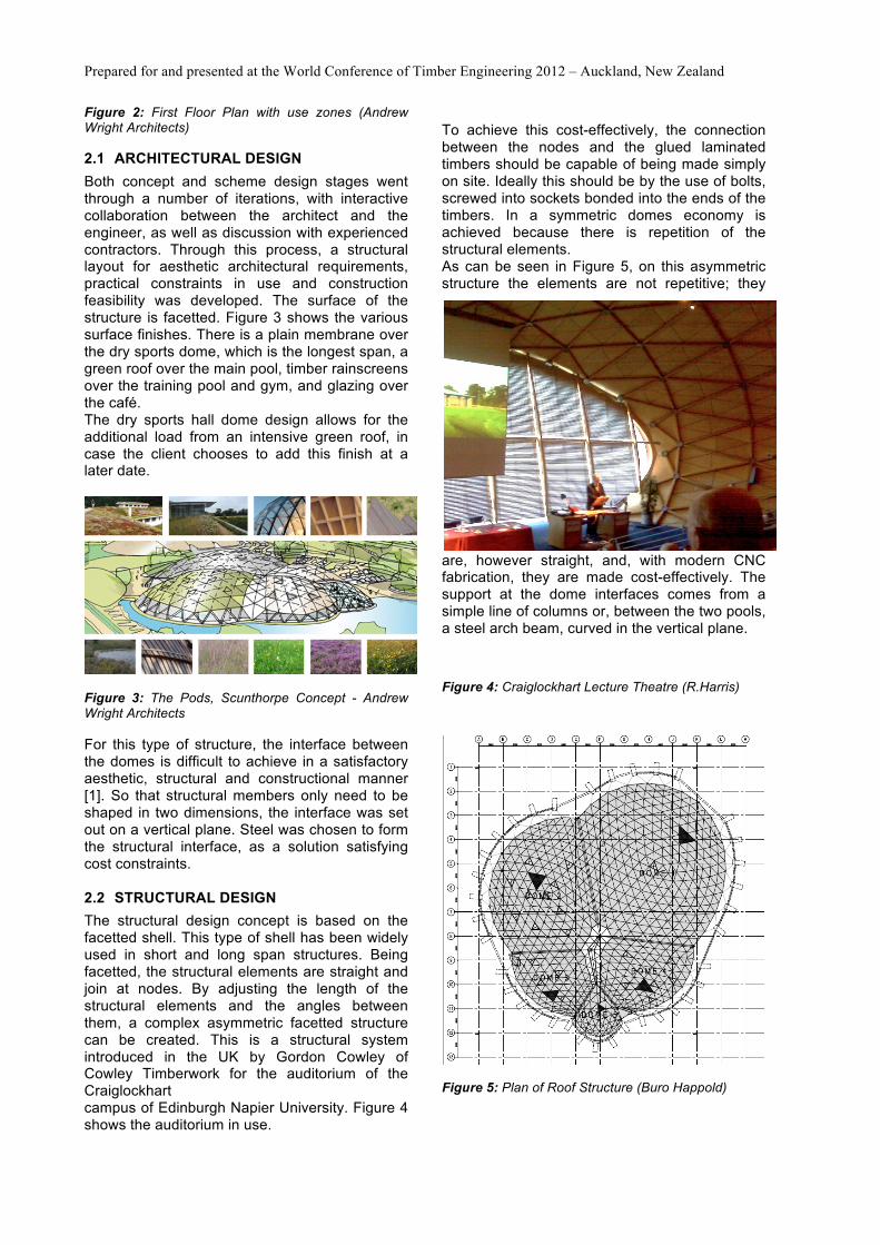
To achieve this cost-effectively, the connection between the nodes and the glued laminated timbers should be capable of being made simply on site. Ideally this should be by the use of bolts, screwed into sockets bonded into the ends of the timbers. In a symmetric domes economy is achieved because there is repetition of the structural elements. As can be seen in Figure 5, on this asymmetric structure the elements are not repetitive; they
are, however straight, and, with modern CNC fabrication, they are made cost-effectively. The support at the dome interfaces comes from a simple line of columns or, between the two pools, a steel arch beam, curved in the vertical plane.
Figure 4: Craiglockhart Lecture Theatre (R.Harris)
Figure 5: Plan of Roof Structure (Buro Happold)

Prepared for and presented at the World Conference of Timber Engineering 2012 – Auckland, New Zealand
3 FORMFINDING The asymmetrical shells are structurally similar to symmetrical geometrically generated domes but have been created in an innovative manner. Methods for form-finding for surfaces and structure grid have been developed for use with gridshell structures [2] and [3]. For this project, the architectural constraints for clearance were defined by the rules given by Sport England [4].
Figure 6: Surfaces defined by "specified" volume (Buro Happold, Bath)
Figure 7: Model of the "hanging" chain lines (Buro Happold, Bath)
Figure 6 shows the constraints envelope. A surface was laid over the constraint envelope to a best fit and then relaxed using the dynamic relaxation form-finding technique (Tensyl software) to create a smooth surface, which did not impinge on the headroom requirements. The hanging chain model is shown in Figure 7 Figure 8 shows the sequence of generating a nodal grid onto the surface and optimising the layout of nodes, prior to creating an analysis model. A number of trials were made to establish the grid.
Figure 8: Process for form-finding, gridding and optimizing for the Pods, Scunthorpe - Buro Happold
At this stage creative design affects the outcome. Different starting points for the nodes, which were adjustment the number of nodes on the perimeter and trials of different principles for setting out the triangular grid on surface, were used. The objective was to maintain a structurally efficient shell and minimise the number of nodes in the final arrangement. This important interactive design process included optimisation, which could have been based upon can be based on various parameters. Figure 9 shows the optimised model as it reached its final stage. The lengths of the members, whilst all being different, were arranged to have as little variation as possible, for each shell. This is the same as optimizing for as little variation as possible in the angles at nodes. The nodes are joined by straight timber elements, producing a reticulated structure which, when clad has flat facetted surfaces.
Figure 9: Model of the main structural arrangement (Buro Happold) The design results in a structure in which selfweight loads generate only compressive stresses in the structure and the material used is minimal. As in any timber dome, due to the excellent strength to weight ratio of the material, the loads due to wind and snow are significant. Thus bending moments and shear forces develop at the nodes and connections must be designed to resist these.

Prepared for and presented at the World Conference of Timber Engineering 2012 – Auckland, New Zealand
4 STRUCTURE 4.1 DESIGN PROCESS The design team completed the drawings to a detailed design stage and invited tenders from main contractors, for a competitive price for overheads and preliminaries and an indicative project price. Included in the tender documents was a list of preferred timber engineering sub-contractors. Buro Happold completed the structural analysis and provided full details (sizes and forces) for the main structural elements. Figure 10 shows the layout of bonded rods in the tender design. By giving forces for the nodes, it was the intention that timber engineering contractors would use their expertise to optimise the design of for the nodes to suit their own methods of fabrication and erection.
Figure 10: Tender design geometry (Buro Happold) The result of the tender was the appointment of Baumer and Kirkland as main contractor with B&K Structures as timber engineering sub-contractor. B&K Structures appointed Westmucket and Hawkes to carry out the detail design the steel nodes and Mayr-Melnhof Kaufmann Reuthe GmbH of Reuthe in Austria as their specialist timber fabricators to carry out development, detailed design and manufacture of the timber and connections. B&K Structures carried out the fabrication of the steel elements and took on the task of erecting the structure. Based on the Buro Happold analysis results and the practical construction planning, B&K Structures built a 3D structural model in TEKLA.
Figure 11: Modelling of the overall support structure with TEKLA (B&K Structures)
Figure 12: Modelling the connecting nodes (B & K Structures)
Figure 13: Modelling the nodes at interface between domes, with steel I-Beam (B & K Structures) Figures 11, 12 and 13 show the layout and details created in the TEKLA model. The choice of system line fell on the central axis of the node timber connecting elements. The structural timber elements were made using Mayr Melnhof Kaufmann Masterline® glulam. 4.2 DESIGN DETAILS The free surface shape of the roof support structure is formed from a network of triangles. The reticulated dome members are straight, glued laminated timber beams, with their ends cut at the correct angles to meet the faces of steel nodes. The integrated architectural/structural design allows for the roof cassette panels to lie on top of the structural members.

Prepared for and presented at the World Conference of Timber Engineering 2012 – Auckland, New Zealand
Figure 14: Section through typical facet of dome, showing main structural members, purlins and roof cassette (Buro Happold)
Figure 15: Elevation on typical facets of dome (Buro Happold) Figures 14 and 15 show the build-up of the cassettes onto the main structural members. It was important to make assumptions about the construction process at the early stage of the design, so that the full build-up could be properly integrated into the design. Through this early design decision, speed of erection was achieved later on, At the node, the connection between the main timber elements and the node is made with parallel fibre, glued threaded rods, which transmit the tensile forces due to bending as well as shear forces. From Buro Happold analysis, shear and tensile forces were determined for each node and Mayr-Melnhof Kaufmann Reuthe were required to design and make node bonded rods to satisfy these design values. The notional designs, in the tender documents, divided the nodes into four categories, Category 1, 2 3 and 4 In the European codes, glued threaded rods are not currently standardised. DIN 1052 gives information on design recommendations for tests and practical applications from test houses and adhesive manufacturers. Mayr-Melnhof Kaufmann were considering M16 and M20 rods for the assembly of the nodes. Even during their sub-contract tender phase, Mayr-Melnhof Kaufmann manufactured specimens, which were tested by the BRE Centre for Innovative Construction Materials at The University of Bath, UK. Figure 16 shows the specimen set-up for tension tests.
Figure 16: Preliminary tensile test for bonded rods (The University of Bath) From these tests, characteristic strength values for threaded rods were determined. From the tests, tensile strength, the statistical methods of BSEN 14358:2006 (calculation of the 5% quantiles for characteristic values and acceptance criteria for samples) were used. 4.3 BONDED RODS Mayr Melnhof Kaufmann conducted a series of pre-production tests at their works. Because the domes house different uses (dry sports and swimming), the exposure categories for the M16 and M20 threaded rods. The components with expected high loads are made with larger 100mm connectors. The following are the characteristic values and average values for the shear strength f k1 and tensile strength R ax, k of each sample size. Results from the tests for M16 and M20 characteristic values were compared according to DIN 1052 F23 Effective bonded length 300mm f k1,k = 3,9 N/mm² > 3,75 N/mm² (from DIN 1052) f k 1, k = 3.9 N / mm ²> 3.75 N / mm ² (DIN 1052) Effective bonded length 400mm f k1,k = 3,6 N/mm² > 3,25 N/mm² (from DIN 1052) f k 1, k = 3.6 N / mm ²> 3.25 N / mm ² (DIN 1052) Effective bonded length 500mm f k1,k = 3,3 N/mm² > 2,75 N/mm² (from DIN 1052) f k 1, k = 3.3 N / mm ²> 2.75 N / mm ² (DIN 1052)

Prepared for and presented at the World Conference of Timber Engineering 2012 – Auckland, New Zealand
The characteristic values or breaking force R ax, K,
k from the tests were compared with those values specified for the project: M16 with l = 300mm R ax, K, k = 73 kN> 70.7 kN M16 with l = 400mm R ax, K, k = 93 kN> 91.0 kN M20 with l = 400mm R ax, K, k = 98 kN> 89.9 kN M20 with l = 500mm R ax, K, k = 113 kN <117 kN * One sample (No. 11) of the 17 reached a value of only 109.50 kN. All others lay between 117.6 kN and 167.2 kN. The average value for Rax,k,m = 143.6 kN The fracture pattern of the samples showed no abnormalities. The threaded rod withdrew wood fibre from a groove in the bonding hole. The characteristic shear strength of the project-related testing is around 50-20% above the standard requirements of DIN 1052. The pre-production tests confirmed the characteristic values of tensile strength from the previous tests carried out at the University of Bath. The fracture patterns of samples with very high values, compared with those with much lower pull-out values, can be distinguished clearly.
Figure 17: Higher load, brittle pull-out specimens (Mayr-Melnhof Kaufmann Reuthe GmbH)
Figure 18: Lower load, ductile pull-out specimens (Mayr-Melnhof Kaufmann Reuthe GmbH)
Higher pull-out values led to splintery fracture of adhesive material, much like shards of glass breaking, with the brittle adhesive bonded to the steel thread, as shown in Figure 17. Often, white-powdered material showed the breakdown region. Samples with a lower pull-out value showed a more ductile pull-out from the timber, as shown in Figure 18. There were different degrees but the wood bondline tended to be covered with a bundle of fibres. 5 CONSTRUCTION Figure 19 shows rods from the series of production tests, which followed the pre-production tests, all carried out by Mayr-Melnhof Kaufmann at their factory in Reuthe, Austria.
Figure 19: Production tests (Mayr-Melnhof Kaufmann Reuthe GmbH) Transport and logistics were straightforward. The Masterline® glulam components with bonded sockets were easily transported and space-optimized on a standard truck (Figure 20). A total of nine trucks drove from Reuthe (Vorarlberg) approximately 1500 km to Scunthorpe in the north of England. This is a key advantage of composite lattice structures. Even this large structure is made using small parts and the transport is hardly noticeable in cost and environmental impact. With relatively low logistics costs, stable and large-scale structures with large spans can be achieved. Since the individual components remain relatively small in dimension and volume, optimized logistics and site installation is achieved by simple means and without heavy equipment. This makes such designs even for distant and/or inaccessible locations very attractive projects.

Prepared for and presented at the World Conference of Timber Engineering 2012 – Auckland, New Zealand
Figure 20: Timber elements wrapped and transported to site (R. Harris) Figure 21 shows the, the prefabricated steel structure for the structural skeleton was fabricated and erected by B&K Structures. This was the first part of the structure to be erected. Once in place, the connections to the domes were checked for accuracy (Figure 21). Tolerances could thus be determined in advance and taken into account in the final fabrication adjustments.
Figure 21: Lightweight steel frame forms skeleton of dome interfaces (B&K Structures) In the next step, the position of individual nodes was determined and set out by means of scaffolding towers. Figure 22 shows the installation of the Masterline ® glulam structural components from the eaves, where they were bolted with steel connector plates to the concrete plinth foundations.
Figure 22: Timber elements erected from the eaves (R. Harris) Because of the self-supporting effect of the dome structure, no complicated assembly scaffolding or protective measures were necessary.
Figure 23: Steel nodes incorporate fixings for temporary props (R. Harris) Fixing points on the nodes allowed temporary prop[s to be easily positioned to enable accurate adjustment Figure 23 shows how the temporary steel props were attached to the nodes. The degree to which tolerances could be initially considered in the planning was limited due to the complex geometry. Small tolerances were easily incorporated in the assembly due to the "rearrangement" effect possible with the nodal system Where gaps remained at the nodes due to larger tolerances, they were filled with a thixotropic epoxy gap-filling adhesive (Rotafix system). In parallel with the construction of the Masterline ® BSH domes, after completion of each dome, construction could begin immediately on the installation of the prefabricated roof panels. Figure 24 shows the roof panel inside surface finish, which was the final finish to the inside of the dome.

Prepared for and presented at the World Conference of Timber Engineering 2012 – Auckland, New Zealand
Figure 24: Completed roof (B&K Structures) The building honestly displays its steel components; its nodes and steel interface beams. In Figure 25, the steel arch beams between the domes can be clearly seen. These could have been hidden by encasement in timber but it was felt preferable to display the building’s hybrid form.
Figure 25: Construction – showing dome interface, utilising steel beams (B&K Structures) 6 BUILDING ENVELOPE The roof envelope, placed over the structural domes is created with pre-fabricated, insulated hollow wooden box elements (Prefalux system), which form the outer covering of the domes. These roof cassettes, shown in Figure 26, meet the requirements for acoustic as well thermal insulation for the roof and incorporate a waterproof membrane on their outer surface. The roof membrane serves as base for various types of roofing finish to the domes. Very different cover types demonstrate integration of architecture with the practical roofing constraints and the surrounding landscape.
Figure 26: Pre-fabricated roof cassettes (B&K Structures) Among the coverings selected by the architect there is a green roof (extensive), two wood-shingle roofs, and a glass and a metal cover (Corus). Figure 27 shows the finished building, with the different surface finishes, as conceived in the architectural concept and realised in the completed building.
Figure 27: Finished building (Buro Happold) 7 CONCLUSIONS The successful outcome of the project was achieved through the support and commitment of the client, North Lincolnshire Council/ Yorkshire Forward. The finished timber building is a striking landmark structure, which is intended to drive regeneration in a city, which is known for its important steel industry. The use of glued laminated timber with galvanised nodes has been shown to be viable and appropriate for this form of structure. The innovative techniques developed for the design, fabrication and construction are replicable for other long span structures. The Pods project at Scunthorpe shows successful projects can arise from good interplay between theory and practice. When working on innovative projects, an open exchange of all involved in the project is necessary. Without this and the will to succeed in the project, modern timber construction cannot advance. There remains a requirement, however, to achieve a balanced and increased interaction

Prepared for and presented at the World Conference of Timber Engineering 2012 – Auckland, New Zealand
between innovative designers, risk-taking contractors, manufacturers and research institutions with open performance standards and regulatory authorities. PROJECT DATA Largest Span: 65 m (dome over dry sports area) Maximum dome height: 20 m Structural Wood volume: 600 m3 Structural Wood grade: Spruce GL32c Structural timber components: approx.. 1100 pieces Number of threaded rods: approximately 4233 pcs Number of standard transports for the timber structure (period: 17.05.2010 - 18.08.2010): Nine Costs Total: £ 21m (approximately € 17.5 million); Wooden construction (including steel): £ 3m (about € 2.5 million) Completion: Mid-2011 ACKNOWLEDGEMENT Client North Lincolnshire Council / Yorkshire Forward Concept Architect Andrew Wright Associates Detail Architect: S&P Architects, London Structural Engineering Buro Happold, Bath, UK Consultants Gardiner & Theobald (Quantity Surveyors); Grant Associates (Landscape Architects); Biodiversity By Design (Biodiversity Design); The University of Bath (Timber / Glulam testing); Mayr-Melnhof Kaufmann Reuthe (Timber / Masterline ® Glulam); Westmucket & Hawkes engineers, London (Connections / Details) Contractors (Main Contractor) Bowmer & Kirkland Group, Belper, UK Timber Construction / Installation B&K Structures Ltd., Belper, UK Timber fabrication: Mayr-Melnhof Kaufmann Reuthe GmbH, Reuthe, Austria REFERENCES [1]Widespan Sports Structures – Versatility with wood. – TRADA/Wood for Good - 2008 [2} Harris, R., 2011. Design of timber gridded shell structures. Proceedings of the Institution of Civil Engineers-Structures and Buildings, 164 (2), pp. 105-116. [3] Harris, R., Haskins, S. and Roynon, J., 2008. The Savill Garden gridshell: design and construction. The Structural Engineer, 86 (17), pp. 27-34 [4] Sport England (2005). Design Guidance Note –Badminton - Published by Sport England - www.sportengland.org [5] Gusinde, Bernd.: Runde Sache. Ingenieurholzbau. Garmisch Partenkirchen 2010
Related Documents

![If you require this document in an alternative format, please … · steel (SS316 grade) as the cathode. ZnO nanostructured films were obtained with KHCO 3 [0.01M] as electrolyte](https://static.cupdf.com/doc/110x72/60980d3d6701e97d731f7522/if-you-require-this-document-in-an-alternative-format-please-steel-ss316-grade.jpg)