SAVE THESE INSTRUCTIONS FOR FUTURE REFERENCE IF 1868 Myers hubs Installation & maintenance information INSTALLATION ( II 2 G Ex eb IIC Gb -55°C to +180°C) • Determine location for the hub mounting hole, making sure there is enough room internally to install the locking nut. Using the dimensions in the table below, machine a mounting hole in the enclosure, following the maximum wall thickness dimensions. • Secure the locking nut to the hub body using the torque values below. Tighten the locking ring set screw. • Using a listed ground lug, install ground (earth) lead, consisting of a maximum of two (2) 6 AWG to 14 AWG solid or stranded copper wires, between the ground bracket and the locknut, and tighten the ground screw to the specified torque. If the available ground (earth) lead AWG is greater than specified, a listed copper lug style connector, specified per NEC, may be utilized. • Reference NEC for ground (earth) lead preparation and insulation stripping requirements. Both screws should be tightened to 35 lb.-in. (4.0 N-m). • This product is designed to be installed only one time. Should the product ever be removed or loosened, the certifications and safety listings on this product shall be terminated. Eaton’s Crouse-Hinds Division IF 1868 1201 Wolf Street, Syracuse, New York 13208 • U.S.A. Revision 2 Copyright © 2019 Revised 05/19 Supercedes 02/19 All statements, technical information and recommendations contained herein are based on information and tests we believe to be reliable. The accuracy or completeness thereof are not guaranteed. In accordance with Eaton’s Crouse-Hinds Division’s “Terms and Conditions of Sale,” and since conditions of use are outside our control, the purchaser should determine the suitability of the product for his intended use and assumes all risk and liability whatsoever in connection therewith. Maximum panel thickness Mounting hole Plastic enclosure Metal enclosure Tightening torque Catalog number (M2) Inches (mm) Inches (mm) Inches (mm) lb.-in. (N-m) SSTGK 1 0.86 - 0.88 (21.8 - 22.4) 0.25 (4.76) 0.25 (4.76) 300 (33.9) SSTGK 2 1.06 - 1.13 (26.9 - 28.7) 0.25 (4.76) 0.25 (4.76) 500 (56.5) SSTGK 3 1.33 - 1.38 (33.8 - 35.0) 0.25 (6.35) 0.25 (6.35) 700 (79.1) SSTGK 4 1.67 - 1.75 (42.4 - 44.5) 0.25 (6.35) 0.25 (6.35) 1000 (113.0) SSTGK 5 1.92 - 2.00 (48.8 - 50.8) 0.25 (6.35) 0.25 (6.35) 1200 (136.0) SSTGK 6 2.39 - 2.50 (60.7 - 63.5) 0.25 (6.35) 0.25 (6.35) 1600 (181.0) SSTGK 7 2.92 - 3.00 (74.1 – 76.2) 0.25 (6.35) 0.25 (6.35) 1600 (181.0) SSTGK 8 3.56 – 3.66 (90.5 – 93.0) 0.25 (6.35) 0.25 (6.35) 1600 (181.0) SSTGK 9 4.06 - 4.17 (103.2 – 106.0) 0.25 (6.35) 0.25 (6.35) 1600 (181.0) SSTGK 10 4.56 - 4.69 (115.9 – 119.0) 0.25 (6.35) 0.25 (6.35) 1600 (181.0) SSTGK 1 to SSTGK 6 thickness range of 0.080” (2mm) - 0.25” (6.35mm) metal enclosure. SSTGK 1 thickness range of 0.125” (2mm) - 0.25” (6.35mm) plastic enclosure. ATEX and IECEx certification numbers do not apply to sizes from SSTGK6 to SSTGK10.

Welcome message from author
This document is posted to help you gain knowledge. Please leave a comment to let me know what you think about it! Share it to your friends and learn new things together.
Transcript

SAVE THESE INSTRUCTIONS FOR FUTURE REFERENCE
IF 1868
Myers hubsInstallation & maintenance information
INSTALLATION ( II 2 G Ex eb IIC Gb -55°C to +180°C)• Determine location for the hub mounting hole, making sure there is
enough room internally to install the locking nut. Using the dimensions in the table below, machine a mounting hole in the enclosure, following the maximum wall thickness dimensions.
• Secure the locking nut to the hub body using the torque values below. Tighten the locking ring set screw.
• Using a listed ground lug, install ground (earth) lead, consisting of a maximum of two (2) 6 AWG to 14 AWG solid or stranded copper wires, between the ground bracket and the locknut, and tighten the ground screw to the specified torque. If the available ground (earth) lead AWG is greater than specified, a listed copper lug style connector, specified per NEC, may be utilized.
• Reference NEC for ground (earth) lead preparation and insulation stripping requirements. Both screws should be tightened to 35 lb.-in. (4.0 N-m).
• This product is designed to be installed only one time. Should the product ever be removed or loosened, the certifications and safety listings on this product shall be terminated.
Eaton’s Crouse-Hinds Division IF 18681201 Wolf Street, Syracuse, New York 13208 • U.S.A. Revision 2Copyright© 2019 Revised 05/19
Supercedes 02/19
All statements, technical information and recommendations contained herein are based on information and tests we believe to be reliable. The accuracy or completeness thereof are not guaranteed. In accordance with Eaton’s Crouse-Hinds Division’s “Terms and Conditions of Sale,” and since conditions of use are outside our control, the purchaser should determine the suitability of the product for his intended use and assumes all risk and liability whatsoever in connection therewith.
Maximum panel thickness
Mounting hole Plastic enclosure Metal enclosure Tightening torqueCatalog number (M2) Inches (mm) Inches (mm) Inches (mm) lb.-in. (N-m)
SSTGK 1 0.86 - 0.88 (21.8 - 22.4) 0.25 (4.76) 0.25 (4.76) 300 (33.9)
SSTGK 2 1.06 - 1.13 (26.9 - 28.7) 0.25 (4.76) 0.25 (4.76) 500 (56.5)
SSTGK 3 1.33 - 1.38 (33.8 - 35.0) 0.25 (6.35) 0.25 (6.35) 700 (79.1)
SSTGK 4 1.67 - 1.75 (42.4 - 44.5) 0.25 (6.35) 0.25 (6.35) 1000 (113.0)
SSTGK 5 1.92 - 2.00 (48.8 - 50.8) 0.25 (6.35) 0.25 (6.35) 1200 (136.0)
SSTGK 6 2.39 - 2.50 (60.7 - 63.5) 0.25 (6.35) 0.25 (6.35) 1600 (181.0)
SSTGK 7 2.92 - 3.00 (74.1 – 76.2) 0.25 (6.35) 0.25 (6.35) 1600 (181.0)
SSTGK 8 3.56 – 3.66 (90.5 – 93.0) 0.25 (6.35) 0.25 (6.35) 1600 (181.0)
SSTGK 9 4.06 - 4.17 (103.2 – 106.0) 0.25 (6.35) 0.25 (6.35) 1600 (181.0)
SSTGK 10 4.56 - 4.69 (115.9 – 119.0) 0.25 (6.35) 0.25 (6.35) 1600 (181.0)
SSTGK 1 to SSTGK 6 thickness range of 0.080” (2mm) - 0.25” (6.35mm) metal enclosure.SSTGK 1 thickness range of 0.125” (2mm) - 0.25” (6.35mm) plastic enclosure.ATEX and IECEx certification numbers do not apply to sizes from SSTGK6 to SSTGK10.

CONSERVE ESTAS INSTRUCCIONES PARA FUTURAS REFERENCIAS
IF 1868
Bujes MyersInformación de instalación y mantenimiento
INSTALACIÓN ( II 2 G Ex eb IIC Gb -55 °C a +180 °C)• Defina la ubicación del orificio de montaje del buje, asegurándose de que haya
suficiente espacio interno para instalar la contratuerca. Utilizando las dimensiones de la siguiente tabla, haga un orificio de montaje en el gabinete, según las dimensiones máximas de espesor de pared.
• Fije la contratuerca al cuerpo del buje según los siguientes valores de torsión. Apretar el tornillo de fijación del anillo de seguridad.
• Usando un terminal a tierra de la lista, instale el cable de conexión a tierra, que consta de un máximo de dos (2) cables de cobre sólido o trenzado de 6 AWG a 14 AWG, entre el soporte de tierra y la contratuerca, y apriete el tornillo de conexión a tierra a la torsión especificada. Si el cable AWG de conexión a tierra disponible es mayor que el especificado, se puede utilizar un conector estilo terminal de cobre señalado en la lista, especificado por el Código eléctrico nacional (National Electric Code, NEC).
• Consulte el NEC para conocer los requisitos de preparación del cable a tierra y de pelado del aislamiento. Ambos tornillos deben ajustarse a 35 lb/in (4,0 N m).
• Este producto está diseñado para ser instalado una sola vez. Si alguna vez se retira o afloja el producto, las certificaciones y los listados de seguridad de este producto deben terminarse.
Todas las declaraciones, la información técnica y las recomendaciones contenidas en este documento se basan en informaciones y pruebas que consideramos confiables. No se garantiza que las mismas sean precisas o estén completas. En conformidad con los “Términos y condiciones de venta” de la División Crouse-Hinds de Eaton y dado a que las condiciones de uso están fuera de nuestro control, el comprador debe determinar la idoneidad del producto para su uso previsto y asume todo riesgo y responsabilidad con relación al mismo.
Espesor máximo del panel
Orificio de montaje Gabinete de plástico Gabinete de metal Torsión de ajusteNúmero de catálogo (M2) Pulgadas (mm) Pulgadas (mm) Pulgadas (mm) lb/in (N m)
SSTGK 1 0,86 - 0,88 (21,8 - 22,4) 0,25 (4,76) 0,25 (4,76) 300 (33,9)
SSTGK 2 1,06 - 1,13 (26,9 - 28,7) 0,25 (4,76) 0,25 (4,76) 500 (56,5)
SSTGK 3 1,33 - 1,38 (33,8 - 35,0) 0,25 (6,35) 0,25 (6,35) 700 (79,1)
SSTGK 4 1,67 - 1,75 (42,4 - 44,5) 0,25 (6,35) 0,25 (6,35) 1000 (113,0)
SSTGK 5 1,92 - 2,00 (48,8 - 50,8) 0,25 (6,35) 0,25 (6,35) 1200 (136,0)
SSTGK 6 2,39 - 2,50 (60,7 - 63,5) 0,25 (6,35) 0,25 (6,35) 1600 (181,0)
SSTGK 7 2,92 - 3,00 (74,1 - 76,2) 0,25 (6,35) 0,25 (6,35) 1600 (181,0)
SSTGK 8 3,56 - 3,66 (90,5 - 93,0) 0,25 (6,35) 0,25 (6,35) 1600 (181,0)
SSTGK 9 4,06 - 4,17 (103,2 - 106,0) 0,25 (6,35) 0,25 (6,35) 1600 (181,0)
SSTGK 10 4,56 - 4,69 (115,9 - 119,0) 0,25 (6,35) 0,25 (6,35) 1600 (181,0)
El rango de espesor de SSTGK 1 a SSTGK 6 es de 0,080” (2 mm) - 0,25” (6,35 mm) en gabinete de metal.El rango de espesor SSTGK 1 es de 0,125” (2 mm) - 0,25” (6,35 mm) en gabinete de plástico.Los números de certificación ATEX e IECEx no aplican a los tamaños de SSTGK6 a SSTGK10.
División Crouse-Hinds de Eaton IF 1868 1201 Wolf Street Syracuse, NY 13208 • EE. UU. Revisión 2 Copyright© 2019 Revised 05/19
Supersedes 02/19
CONSERVER CES INSTRUCTIONS À TITRE DE RÉFÉRENCE
IF 1868
Moyeux MyersInformation sur l’installation et l’entretien
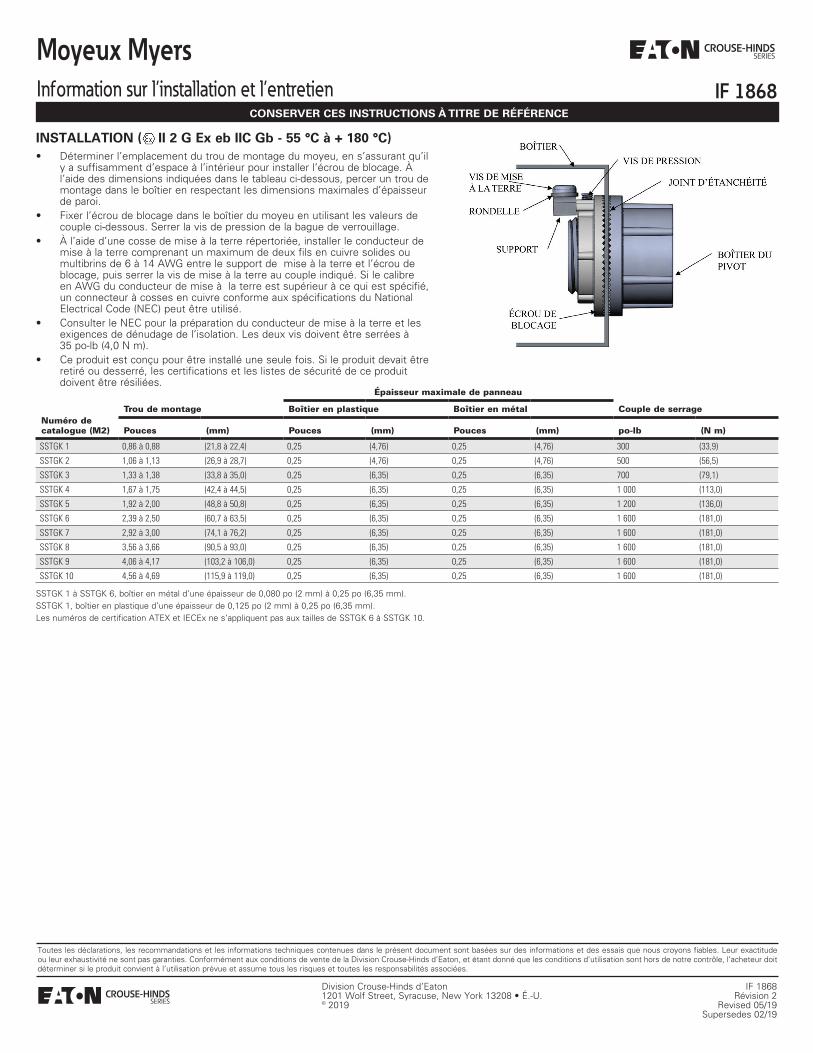
INSTALLATION ( II 2 G Ex eb IIC Gb - 55 °C à + 180 °C)• Déterminer l’emplacement du trou de montage du moyeu, en s’assurant qu’il
y a suffisamment d’espace à l’intérieur pour installer l’écrou de blocage. À l’aide des dimensions indiquées dans le tableau ci-dessous, percer un trou de montage dans le boîtier en respectant les dimensions maximales d’épaisseur de paroi.
• Fixer l’écrou de blocage dans le boîtier du moyeu en utilisant les valeurs de couple ci-dessous. Serrer la vis de pression de la bague de verrouillage.
• À l’aide d’une cosse de mise à la terre répertoriée, installer le conducteur de mise à la terre comprenant un maximum de deux fils en cuivre solides ou multibrins de 6 à 14 AWG entre le support de mise à la terre et l’écrou de blocage, puis serrer la vis de mise à la terre au couple indiqué. Si le calibre en AWG du conducteur de mise à la terre est supérieur à ce qui est spécifié, un connecteur à cosses en cuivre conforme aux spécifications du National Electrical Code (NEC) peut être utilisé.
• Consulter le NEC pour la préparation du conducteur de mise à la terre et les exigences de dénudage de l’isolation. Les deux vis doivent être serrées à 35 po-lb (4,0 N m).
• Ce produit est conçu pour être installé une seule fois. Si le produit devait être retiré ou desserré, les certifications et les listes de sécurité de ce produit doivent être résiliées.
Division Crouse-Hinds d’Eaton IF 18681201 Wolf Street, Syracuse, New York 13208 • É.-U. Révision 2© 2019 Revised 05/19
Supersedes 02/19
Toutes les déclarations, les recommandations et les informations techniques contenues dans le présent document sont basées sur des informations et des essais que nous croyons fiables. Leur exactitude ou leur exhaustivité ne sont pas garanties. Conformément aux conditions de vente de la Division Crouse-Hinds d’Eaton, et étant donné que les conditions d’utilisation sont hors de notre contrôle, l’acheteur doit déterminer si le produit convient à l’utilisation prévue et assume tous les risques et toutes les responsabilités associées.
Épaisseur maximale de panneau
Trou de montage Boîtier en plastique Boîtier en métal Couple de serrageNuméro de catalogue (M2) Pouces (mm) Pouces (mm) Pouces (mm) po-lb (N m)
SSTGK 1 0,86 à 0,88 (21,8 à 22,4) 0,25 (4,76) 0,25 (4,76) 300 (33,9)
SSTGK 2 1,06 à 1,13 (26,9 à 28,7) 0,25 (4,76) 0,25 (4,76) 500 (56,5)
SSTGK 3 1,33 à 1,38 (33,8 à 35,0) 0,25 (6,35) 0,25 (6,35) 700 (79,1)
SSTGK 4 1,67 à 1,75 (42,4 à 44,5) 0,25 (6,35) 0,25 (6,35) 1 000 (113,0)
SSTGK 5 1,92 à 2,00 (48,8 à 50,8) 0,25 (6,35) 0,25 (6,35) 1 200 (136,0)
SSTGK 6 2,39 à 2,50 (60,7 à 63,5) 0,25 (6,35) 0,25 (6,35) 1 600 (181,0)
SSTGK 7 2,92 à 3,00 (74,1 à 76,2) 0,25 (6,35) 0,25 (6,35) 1 600 (181,0)
SSTGK 8 3,56 à 3,66 (90,5 à 93,0) 0,25 (6,35) 0,25 (6,35) 1 600 (181,0)
SSTGK 9 4,06 à 4,17 (103,2 à 106,0) 0,25 (6,35) 0,25 (6,35) 1 600 (181,0)
SSTGK 10 4,56 à 4,69 (115,9 à 119,0) 0,25 (6,35) 0,25 (6,35) 1 600 (181,0)
SSTGK 1 à SSTGK 6, boîtier en métal d’une épaisseur de 0,080 po (2 mm) à 0,25 po (6,35 mm).SSTGK 1, boîtier en plastique d’une épaisseur de 0,125 po (2 mm) à 0,25 po (6,35 mm).Les numéros de certification ATEX et IECEx ne s’appliquent pas aux tailles de SSTGK 6 à SSTGK 10.

BEWAHREN SIE DIESE ANWEISUNGEN FÜR ZUKÜNFTIGE REFERENZZWECKE AUF
IF 1868
Myers-VerteilerInformationen zu Installation und Instandhaltung
INSTALLATION ( II 2 G Ex eb IIC Gb -55 °C bis +180 °C)• Bestimmen Sie eine Stelle für die Befestigungsbohrung des Verteilers. Dabei
sollte im Inneren genügend Platz zur Montage der Kontermutter vorhanden sein. Bohren Sie anhand der Abmessungen in der Tabelle unten eine Befestigungsbohrung in das Gehäuse, die sich nach der maximalen Wanddicke richtet.
• Befestigen Sie die Kontermutter mit den folgenden Drehmomentwerten am Verteilergehäuse. Ziehen Sie die Stellschraube des Verschlussrings fest.
• Installieren Sie mit einer gelisteten Erdfahne das Erdungskabel, das aus maximal zwei (2) 6 AWG bis 14 AWG festen oder verseilten Kupferkabeln bestehen muss, zwischen der Erdungsklammer und der Kontermutter und ziehen Sie die Erdungsschraube mit dem angegebenen Drehmoment an. Falls das verfügbare Erdungskabel AWG größer ist als spezifiziert, kann eine gelistete Kupferfahne gemäß NEC verwendet werden.
• Ziehen Sie bezüglich der Vorbereitung des Erdungskabels und der Anforderungen zum Abisolieren NEC zurate. Beide Schrauben sollten auf 35 lb.-in. (4,0 Nm) angezogen werden.
• Dieses Produkt kann nur einmal installiert werden. Sollte das Produkt jemals entfernt oder gelockert werden, werden die Zertifizierungen und Sicherheitslisten dieses Produkts beendet.
Eaton’s Crouse-Hinds Division IF 18681201 Wolf Street, Syracuse, New York 13208 • USA Revision 2Copyright© 2019 Revised 05/19
Supercedes 02/19
Alle Aussagen, technischen Daten und Empfehlungen basieren auf Informationen und Tests, die wir als zuverlässig erachten. Die Richtigkeit und Vollständigkeit derselben sind nicht gewährleistet. In Übereinstimmung mit den allgemeinen Geschäftsbedingungen von Eatons Crouse-Hinds Division für den Verkauf, und da die Einsatzbedingungen für unsere Produkte nicht unserer Kontrolle unterliegen, muss der Käufer die Eignung des Produktes für die vorgesehene Verwendung selbst einschätzen. Der Käufer übernimmt alle Risiken und die Haftung in Zusammenhang mit der Benutzung des Produkts.
Maximale Tafeldicke
Befestigungsbohrung Kunststoffgehäuse Metallgehäuse AnzugsdrehmomentKatalognummer (M2) Zoll (mm) Zoll (mm) Zoll (mm) lb.-in. (Nm)
SSTGK 1 0,86 - 0,88 (21,8 - 22,4) 0,25 (4,76) 0,25 (4,76) 300 (33,9)
SSTGK 2 1,06 - 1,13 (26,9 - 28,7) 0,25 (4,76) 0,25 (4,76) 500 (56,5)
SSTGK 3 1,33 - 1,38 (33,8 - 35,0) 0,25 (6,35) 0,25 (6,35) 700 (79,1)
SSTGK 4 1,67 - 1,75 (42,4 - 44,5) 0,25 (6,35) 0,25 (6,35) 1000 (113,0)
SSTGK 5 1,92 - 2,00 (48,8 - 50,8) 0,25 (6,35) 0,25 (6,35) 1200 (136,0)
SSTGK 6 2,39 - 2,50 (60,7 - 63,5) 0,25 (6,35) 0,25 (6,35) 1600 (181,0)
SSTGK 7 2,92 - 3,00 (74,1 - 76,2) 0,25 (6,35) 0,25 (6,35) 1600 (181,0)
SSTGK 8 3,56 - 3,66 (90,5 - 93,0) 0,25 (6,35) 0,25 (6,35) 1600 (181,0)
SSTGK 9 4,06 - 4,17 (103,2 - 106,0) 0,25 (6,35) 0,25 (6,35) 1600 (181,0)
SSTGK 10 4,56 - 4,69 (115,9 - 119,0) 0,25 (6,35) 0,25 (6,35) 1600 (181,0)
SSTGK 1 bis SSTGK 6 Dickebereich von 0,080 Zoll (2 mm) bis 0,25 Zoll (6,35 mm) Metallgehäuse.SSTGK 1 Dickebereich von 0,125 Zoll (2 mm) bis 0,25 Zoll (6,35 mm) Kunststoffgehäuse.Die ATEX- und IECEx-Zertifizierungsnummern gelten nicht für die Größen SSTGK 6 bis SSTGK 10.
Related Documents