DOT/FAA/RD-90/8 Analysis of Helicopter Mishaps at Heliports, Research and Development Service Airports, and Unimproved Washington, D.C. 20591 Sites (Research and Development Service Federal Aviation Administration Washington, D.C. 20591 DTI IELECTEI S2EB1 1991. January 1991 Final Report This document is available to the public through the National Technical Information Service, Springfield, Virginia 22161. 0 US Department of TranrrF-ot!:on Federal Aviation Administration S1 2K 19

Welcome message from author
This document is posted to help you gain knowledge. Please leave a comment to let me know what you think about it! Share it to your friends and learn new things together.
Transcript
DOT/FAA/RD-90/8 Analysis of HelicopterMishaps at Heliports,
Research and Development Service Airports, and UnimprovedWashington, D.C. 20591 Sites
(Research and Development ServiceFederal Aviation AdministrationWashington, D.C. 20591
DTIIELECTEIS2EB1 1991.
January 1991
Final Report
This document is available to the publicthrough the National Technical InformationService, Springfield, Virginia 22161.
0US Departmentof TranrrF-ot!:onFederal AviationAdministration
S1 2K 19
NOTICE
This document is disseminated under the sponsorship of the U.s,Department of Transportation in the interest of information exchange.The United States Government azsumec no liability for the content:: or usethereof.

Technical Report Documentation Page
Report No. 2. Government Accession No 3. Recipient's Catalog No.
DOT FAAIRD-90"8
Title and Subtitle 5. Report Date
Analysis of Helicopter Mishaps at Heliports, January 1991
Airports, and Unimproved Sites 6. Performing Organization Code
Author (s) 8. Performing Organization Report No.
L. D. Dzamba, R. J. Hawley, R. J. Adams SCT No. 90RR-46
Performing Organization Name and Address 10. Work Unit No. (TRAIS)
Systems Control Technology, Inc.1611 North Kent Street, Suite 910 11. Contract or Grant No.Arlington, Virginia 22209 DTFA01-87-C-00014
2. Sponsoring Agency Name and Address 13. Type Report and Period Coveied
U.S. Department of Transportation Final ReportF A-,a- Aviatinn Adminis!r53tion800 Independence Avenue, S.W. 14. Sponsoring Agency CodeWashington, D.C. 20591 ARD - 30
5. Supplementary Notes
ARD - 30 Vertical Flight Program Office
16. Abstract
A task was undertaken to determine possible inadequacies in FAA design standards ard guidelines set forthin the Heliport Design Advisory Circular (AC 150/5390-2). This report is based upon the results of an analysisof helicopter mishaps which occurred within a 1 mile radius of various landing sites, including heliports,airports. and unimproved sites. NTSB and U.S. Army reports describing mishaps tlit occurred at or near afacility were used. The focus of the analysis was to determine the manner in which facility design maycontribute to mishaps. Particular attention was given to issues concerning the size, obstruction clearance,
'-d adequacy of facility protected airspace and operational areas. Mishap type and location, as well as theapplicable design issues, were analyzed from the reports and are discussed.
This study concludes that overall, the Heliport Design Advisory Circular provides very good guidelines forheliport design and is a valid instrument. Several areas for possible improvement within the document havebeen identified. Recommendations include areas addressing obstruction marking, facility maintenance, windindicator location, and guidelines for operations at airports.
This report is one in a series of three dealing with rotorcraft accidents at heliports, airports, and unimprovedhelicopter landing sites. The other reports are:
"Analysis of Helicopter Accident Risk Exposure at Heliports, Airports, and Unimproved Sites,"DOTiFAA!RD-90/9, and"Composite Profiles of Helicopter Mishaps at Heliports and Airports," DOT/FAA/RD-91ii.
7. Key Words 18. Distribution Statement
Airport Mishap This document is available to the U.S. publicHelicopter Safety through the National Technical InformationHelipcr! U.S. Army Service, Springfield, Virginia 22161.
19. Securiy Classif. (of this report) 20. Security Classif. (of this page) 21. No. of Pages 22. Price
Unclassified Unclassified
orm DOT IF 1700.7 (8-72) Reproduction of this document is authori~ed
PREFACE
The research effort herein was managed by the Federal AviatiunAdministration (FAA) Vertical Flight Program Office (ARD-30) undercontract to Systems Control Technology (SCT), Air Transportation SystemsDivision, Arlington, VA. SCT was assisted in this effort by AdvancedAviation Concepts (AAC) of Jupiter, Florida. Two of the authors,Mr. Len Dzamba and Mr. Robert Hawley are with sui. Mr. Richard Adams isemployed by AAC.
/
Accession For
NTIS TRA&IDTIC TAB CUnannounced [Justification
ByD_istribiution/
AvailabilltY Codes
7vall and/orIst Spooa1
tl'
TABLE OF CONTFNTS
Page
1.0 Introduction........................................................ 11.2. Purpose........................................................ 11.2 Background..................................................... 11.3 Document Use................................................... 3
2.0 Methodology overview................................................ 52.1 Database Search and Data Collection........................... 52.2 In-Depth Analysis.............................................. 52.3 Advisory Circular Recommendations............................. 5
3.0 Mishap Dataise Search.............................................. 73.1 Data C~ilection................................................ 7
3.1.1 Civil Mishap Data Source................................ 73.1.2 Military Mishap Data Sources........................... 9
3.2 Mishap Summaries............................................... 93.2.1 NTSB Mishap Summaries.................................. 10
3.2.1.1 1964 Through 1981............................. 103.2.1.2 1982.......................................... 133.2.1.3 1983 Through 1986............................. 13
3.2.2 Military Mishap Summaries.............................. 133.3 Mishap Selection ............................................... 14
4.0 In-Depth Analysis.................................................. 174.1 Number of Mishaps............................................. 174.2 Facility Type......................................... ........ 174.3 Desired Details............................................... 194.4 Mishap Summary Form........................................... 21
4.4.1 Facility Mishap Location............................... 214.4.2 Mishap Type............................................ 234.4.3 Heliport Design issues................................. 23
4.5 NTSB Mishap Reports........................................... 234.6 U.S. Army Mishap Reports...................................... 23
5.0 Results............................................................. 255.1 General Factors............................................... 25
5.1.1 Mishap Locations....................................... 25*5.1.2 Mishap Types........................................... 25
5.1.2.1 Obstruction Strikes (on-facility) .............275.1.2.2 Obstruction Strikes (off-facility) ............335.1.2.3 Forced Landings on Takeoff.................... 345.1.2.4 Rotorwash Damage.............................. 345.1.2.5 Wind indication............................... 35.1.2.6 Collision with Other Aircraft .................345.1.2.7 Insufficient Climb Angle ................. .... 355.1.2.8 Forced Landing During Final Approach ......... 355.1.2.9 Stuck Landing Gear............................ 355.1.2.10 Refueling Fire................................ 35
5. )r~iu issues........... ................................ ..... Y5.2.1 Approach/Departure Obstruction Marking/Clearance
(21.4 percent of mishaps)..... ........................ 365.2.2 Approach/Departure Croundspace (18.8 percent of
mishaps)............................................... 36
iii
Page
5.2.3 Parking Area Design (17.9 percent of mishaps) ......... 365.2.4 FATO Design (14.5 percent of mishaps) ................. 385.2.5 Refueling Area Design (6.8 percent of mishaps) ........ 385.2.6 Wind Indicator (6.0 percent of mishaps) ............... 395.2.7 Surface Composition/Maintenance (4.3 percent of
mishaps) ............................................... 395.2.8 Taxiway Design (2.6 percent of mishaps) ............... 395.2.9 Lighting Structures (2.6 percent of mishaps) .......... 395.2.10 Fire Fighting Equipment (1.7 percent of mishaps) ...... 40
5.3 operational Issues ........................................... 405.3.1 Passengar Loading/Unloading ........................... 405.3.2 Ground Marshal Availability/Training .................. 40
6.0 Conclusions and Recommendations ................................... 436.1 Advisory Circular Overview ................................... 436.2 Facility Design Issues ....................................... 44
6.2.1 Mishap Locations ...................................... 446.2.2 Heliport Design issues ................................ 446.2.3 Airport Design Issues ................................. 47
6.3 Civilian Mishap Data ......................................... 506.3.1 Update NTSB Mishap Form ............................... 50
6.3.2 Include Incidents in Database ......................... 506.3.3 Public Service Mishaps ................................ 51
6.4 Tail Rotor Paint Schemes ..................................... 516.5 Future Considerations ........................................ 51
References .............................................................. 53List of Acronyms ........................................................ 55
Appendix A Supplement G - Rotorcraft ................................. A-1Appendix B Supplement Q - Airport/Airstrip ........................... B-1Appendix C NTSB Investigator's Report Form (1978 through 1981) ....... C-1Appendix D NTSB Investigator's Report Form (1982) .................... D-1Appendix E NTSB Factual Report Form (1983 through 1986) .............. E-1
iv
LIST OF FIGURES
Page
Figure 1 Methodology Flowchart ........................................ 6Figure 2 Mishap Location Information (NTSB Mishap Forms) ............. 8Figure 3 NTSB Mishap Summaries ....................................... 1IFigure 4 U.S. Army Mishap Summaries .................................. 12Figure 5 Mishap Seiection Summary .................................... 18Figure 6 VFR Heliport Protected Airspace Surfaces .................... 20Figure 7 Mishap Summary Form ......................................... 22Figure 8 FaciiiLy Mishap Locations ................................... 26Figure 9 General Mishap Types ......................................... 29Figure 10 Mishap Types at Heliports................................... 30Figure 11 Mishap Types at Airports .................................... 31Figure 12 Mishap Types at Other Locations ............................. 32Figure 13 General Design Issues ....................................... 37Figure 14 Proposed Obstruction Marking Zone .......................... 46
LIST OF TABLES
Table 1 Aircraft axhd Operational Factors ............................. 19Table 2 Facility Mishap Location ..................................... 21Table 3 Percent U.S. Army Mishaps By Class ........................... 24Table 4 Mishap Type .................................................. 28Table 5 Mishap by Type of Operation .................................. 27
V
1.0 INTRODUCTION
1.1 PURPOSE
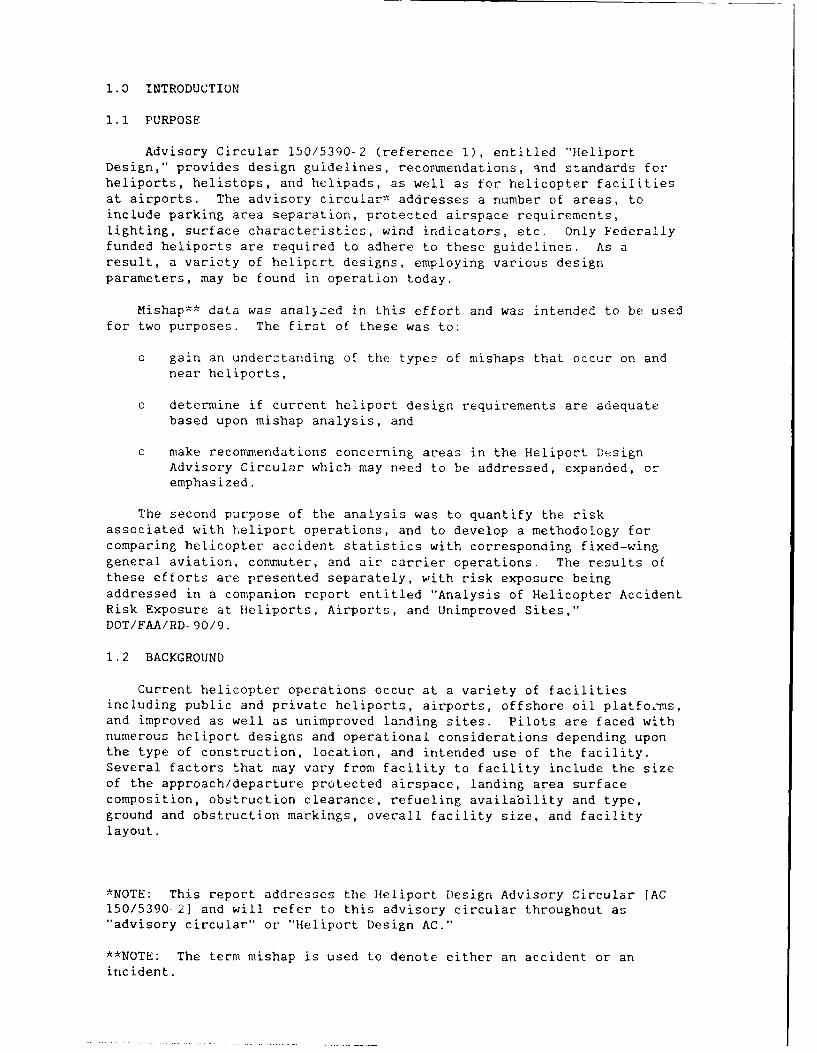
Advisory Circular 150/5390-2 (reference 1), entitled "HeliportDesign," provides design guidelines, recommendations, qnd standards forheliports, helistops, and helipads, as well as for helicopter facilitiesat airports. The advisory circular* addresses a number of areas, toinclude parking area separation, protected airspace requirements,lighting, surface characteristics, wind indicators, etc. Only Federallyfunded heliports are required to adhere to these guidelines. As aresult, a variety of helipcrt designs, employing various designparameters, may be found in operation today.
Mishap** data was anal~zed in this effort and was intended to be usedfor two purposes. The first of these was to:
o gain an understanding of the types of mishaps that occur on andnear heliports,
o determine if current heliport design requirements are adequatebased upon mishap analysis, and
o make recommendations concerning areas in the Heliport DesignAdvisory Circular which may need to be addressed, expanded, oremphasized.
The second purpose of the analysis was to quantify the riskassociated with heliport operations, and to develop a methodology forcomparing helicopter accident statistics with corresponding fixed-winggeneral aviation, commuter, and air carrier operations. The results ofthese efforts are presented separately, with risk exposure beingaddressed in a companion report entitled "Analysis of Helicopter AccidentRisk Exposure at Heliports, Airports, and Unimproved Sites,"DOT/FAA/RD-90/9.
1.2 BACKGROUND
Current helicopter operations occur at a variety of facilitiesincluding public and private heliports, airports, offshore oil platfornns,and improved as well as unimproved landing sites. Pilots are faced withnumerous heliport designs and operational considerations depending uponthe type of construction, location, and intended use of the facility.Several factors that may vary from facility to facility include the sizeof the approach/departure protected airspace, landing area surfacecomposition, obstruction clearance, refueling availability and type,ground and obstruction markings, overall facility size, and facilitylayout.
*NOTE: This report addresses the Heliport Design Advisory Circular [AC150/5390-2] and will refer to this advisory circular throughout as"advisory circular" or "Heliport Design AC."
**NOTE: The term mishap is used to denote either an accident or anincident.
Several research and development projects have been undertaken toquantify various aspects of heliport design as it relates to helicopterperformance. These include:
o "Heliport Surface Maneuvering Test Results," DOT/FAA/CT-TN88/30,(reference 2),
o "Heliport VFR Airspace Based on Helicopter Performance,"DOT/FAA/RD-90/4, (reference 3),
o "Helicopter Physical and Performance Data," DOT/FAA/RD-90/3,(reference I),
o "Helicopter Rejected Takeoff Airspace Requirements,"DOT/FAA/RD-90/7, (reference 5),
o "Evaluating Wind Flow Around Buildings on Heliport Placement,"DOT/FAA/PM-84/25, (reference 6), and
o "Rotorcraft Acceleration and Climb Performance Model,"DOT/F'AA/RD-90/6, (reference 7).
These undertakings were concerned with the requirements and adequacyof heliport protected airspace, parking and maneuvering separation,rejected takeoff ground/airspace, and wind flow analysis as they relateto current heliport design guidelines and actual helicopter performance.In addition to those mentioned above, a current research effort isendeavoring to understand and model the dynamics of rotorwash. A numberof these projects have recommended that one or more of the currentheliport design standards be revised or revisited. However, beforemaking any changes to the advisory circular, it was recognized that areview of the historical mishap database should be undertaken tounderstand the nature of mishaps that have occurred or may have a highprobability for occurrence at heliports. This report presents theresults of that analysis.
Because the term "heliport" may be interpreted differently and mayinclude various types and locations of facilities, the term "heliport,"as it applies to this study, is defined as any facility that isdesignated a heliport, whether stand-alone or at an airport, and anylocation for which the obvious intended use is as a heliport. Forinstance, a barge, parking lot, or even an individual's backyard that wasused regularly for helicopter operations was considered a heliport. Onthe other hand, a location which is used as a takeoff/landing area onlyonce or twice was placed in the "other" facility category. Thisdefinition is generally consistent with the following definition which iscontained in the Heliport Design AC.
"A heliport is an identifiable area on land, water, or structure,inluding any building or facilities thereon, used or intended to beused for the landing and takeoff of helicopters.'
Offshore oil-platform mishaps were intentionally excluded from thisanalysis, since offshore landing facilities are not addressed in theHeliport Design AC and are not normally available for public use.Offshore oil platform design for helicopter use is addressed in aseparate document entitled "Offshore Heliport Design Guide,"reference 8. This document is published by the Louisiana Department ofTransportation and Development and is accepted as the industry standard.
2
1.3 DOCUMENT USE
The primary focus of this study was to review 7 :igri Sr a hwhich have occurred at or within I mile of heiiports (thrcughou '*hdocument we will r er to such -ishaps as taking piae "nea" iort:airports, or unimproved sites). However, early ir. the stud,, it wasrealized that there were relatively few such rnishars which occl. nearheliports and very few which occur rear p1blic usc heliports. T,re fori,in ordar to obtain enough inform.ation to examine dsi gn-re lated mishapcauses, it was necessary to include mishaps which hav. occurred nearairports as well as unimproved sites. Of the 117 civil and rilitarymishaps used in the study, 4 mishaps (3 percent) occusred near pulc useheliports, 41 (35 percent) occurred near private helipcorts, 4' 13%percent) occurred near airpcrts, and 31 (27 percentj occusre'! noarunimproved landing sites.
By reviewing design- related mishaps, potential design relasedshortcomings can be understood and measures can be taken to iortherreduce the already low number of such occurrences. It is, hr.i~c that bylooking at the types of mishaps that may occur near heliports, airports,and unimproved sites, this document will be used by helipor> and airportdesigners to assist them in their facility design effort!-.
Also included in this document are discussions of operational factorsthat have contributed to several of the mishaps. These discussionshighlight the importance of good operational procedures. Theseoperational procedures are not necessarily related to design issues butdo contribute to a safer heliport environment. Discussion rLlating toopecational cause factors can be used by pilots and flight instructors tohelp understand the role operational factors may have in causingmishaps.
This document can be used both for training and for risk ranagementanalysis. The intended audience includes heliport designers, heliportoperators, flight instructors, qnd pilots.
3
2.0 METHO[ )LOGY OVERVIEW
The basic methodology usd f r this s-turyz i .......... - ..
2.1 DATABASE SEARCH AND DATA COLLECTIO1
The initial effort was to collect helicopter mishap summaries. Tsensure that all operators and types of operations using public andprivate facilities were included, mishap summaries were solicited fro.both civil anid military sources. Mishap summaries were received from theNational Transportation Safety Board (NTSB) and the United States Army.Once the mishap summaries were reviewed, full reports for those mishapsdeemed appropriate to the study were ordered flor in-depth analysis.
2.2 IN-DEPTH ANALYSIS
An in-depth d.lalysis of each full mishap report was then performed.Particular attention was given to dimensional, surface, and protectedairspace issues. These factors were of particular importance, since theyrepresent the basic characteristics of heliport design and comprise theprimary focus of the Heliport Desi-n AC.
2.3 ADVISORY CIRCULAR RECOMMENDATIONS
Based upon the analysis, areas of the Heliport Design AC requiringrevision, expansion, or increased emphasis were identified and, wheresupporting d: ta was available, recommendations for change were made.
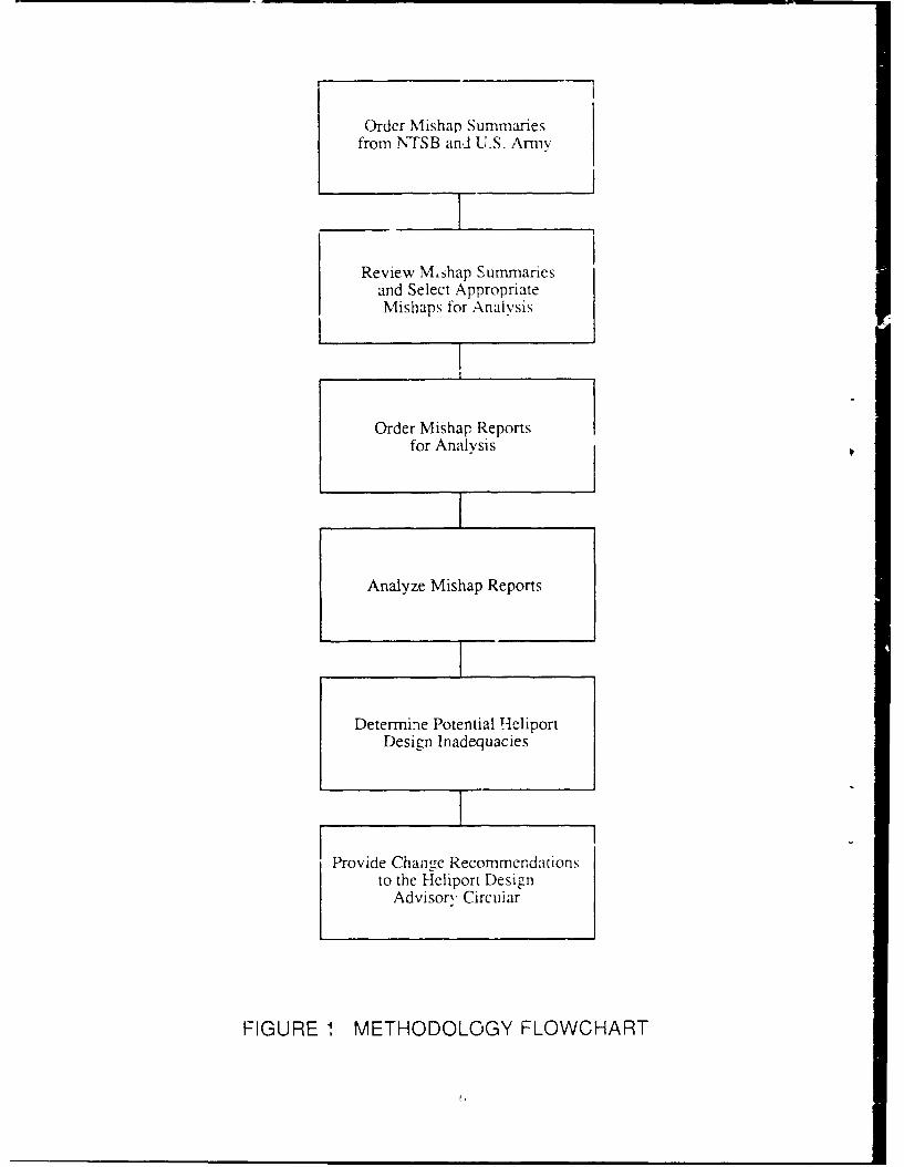
Order Mishap Summariesfrom NTSB and U.S. Army
Review Mshap Summariesand Select AppropriateMishaps for Analysis
Order Mishap Reportsfor Analysis
Analyze Mishap Reports
Determine Potential HeliportDesign Inadequacies
Provide Change Recommendationsto the Heliport Design
Advisory Circuiar
FIGURE 1 METHODOLOGY FLOWCHART
3.0 MISHAP DATABASE SEARCH
3.1 DATA COLLECTION
In order to assure a level of completeness and accuracy, it wnsdeemed desirable to include a minimum of 100 heliport mishaps in thein-depth analysis. At the start of this effort the number of helicoptermishaps contained in the civil mishap database, as well as the quantliyand quality of data available, was unknown. It was therefore decideithat mishap reports from both civil and military sources would be used.Although the missions of the two groups differ significantly, theirrespective operations on or about heliports are principally the same. Infact, many military operations do occur at civilian facilities. None ofthe selected military mishaps included operations that were unique tomilitary missions near the landing site. For example, missions that mayhave required nap-of-the-earth (NOE) flying near che landing facilitywere not included.
To ensure that the full spectrum of mishaps that occurred at or neara landing site would be considered for the study, mishaps over a 22 yearperiod from 1964 through 1986 were initially included. While the type,quality, and completeness of both civil and military mishap reports overthis broad range of years was uncertain, any narrowing of the source datacould only be considered after the available data set was known.
Data sources used in this study were limited to United Statesgovernment agencies. This was done for several reasons, the most basicbeing that the Heliport Design AC is written for U.S. helipc ' andairports. In addition, the type, quality, availability and tieliness inreceiving international mishap reports was highly uncertain. Thisuncertainty was thought to be an inappropriate burden to the study.
3.1.1 Civil Mishap Data Source
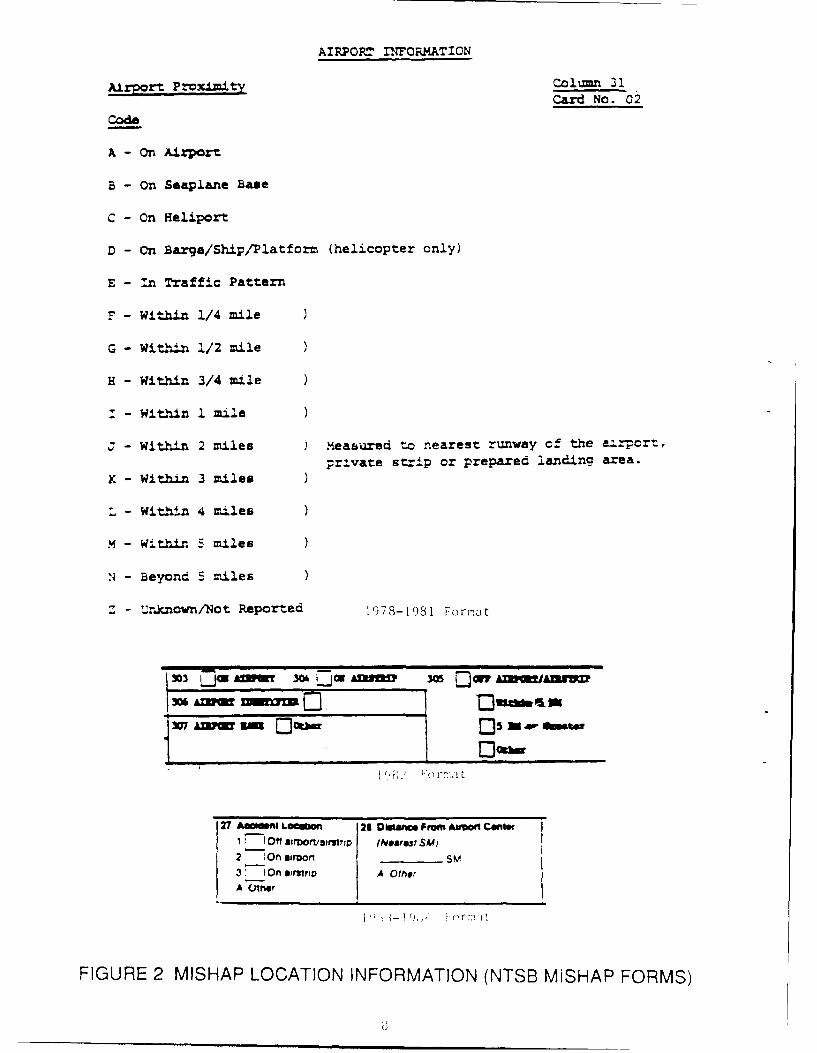
Mishap reports and statistics for civil mishaps in the United Statesare reccrded and maintained by the National Transportation Safety Board(NTSB) iv Washington, D.C. The NTSB was contacted, and a request wasmade to obtain a copy of each factual report and mishap summary forhelicopter mishaps occurring from 1964 through 1986. The Heliport DesignAn provides guidelines for protected airspace out to 4,000 feet from theedge of the takeoff/landing area of a heliport. It was thereforedesirable to review those mishaps which occurred both on and within 4,000feet of the heliport. The request to the NTSB stipulated that only:ishap:: that occurred on or within one mile of a heliport be included.The criterion of "within 1 mile" was used as a selection device becauseit is the nearest division to the advisory circular's 4,000 feet that theNTSB has used for mishap location in their reports. The study reviewedmishaps that took place within I mile and selected for further reviewonly those that appearcd to be related to heliport design issues.
NTSB mishap forms were revised several times throughout the pcriodconsidered. One of the items significant to this study that has changedseveral times on the mishap report form is the recording of th; distancefrom the landing site that the mishap occurred. Figure 2 shows how thisinformation ha: been recorded and how this recorded information has
AIRPORT 2NFORMATION
Airport Proximity Colun 31Card No. 02
Code
A - On Azport
B - On Seaplane Base
C - On Heliport
D - On Barge/Ship/Platform (helicopter only)
E - In Traffic Pattern
F - Within 1/4 mile
G - Wit.hin 1/2 mile
H - Within 3/4 mile
I - Within I mile
3 - Within 2 miles measured to nearest runway cf the a-rpor-,private strip or prepared landing area.
K - Within 3 miles
L - Within 4 miles
M - Within 5 miles
N - Beyond 5 miles
Z - Unknown/Not Reported 1978-1981 Fornat
1303 Dn0 -Aow wo 5p AjW
27 Am ifnt Lourn 21 DOe Frm A~I Cent1 0" O affonr,t/2r (NeeirsI SM)
2 Ion aarmor ______
37 1On airhtrip A OtherA (flflr
FIGURE 2 MISHAP LOCATION INFORMATION (NTSB MISHAP FORMS)

changed over the years. The 1982 factual report recorj:s ao at lo,. -.being within or outside 5 statute mike:s of the airpo:'L, a dr'i;tic chr,.-to the 1/'; mile accuracy previously required. In mor-. recent year?,factual report form has recorded the distance to the nearest statuot.mile. Also of note in this data field is that prior to. 198? the term-"heliport" was included on the mishap form.
Supplemental forms for use in mishap investigations were madeavailable to NTSB investigators beginning in 1983. These forms contain:additional information which is not included on the primary factualreport form. In particular, supplement G (appendix A) entitled"Rotorcraft" contains information about the aircraft which is exclus:V.for rotorcraft purposes. Supplement Q (appendix B) entitled"Airport/Airstrip" contains information concerning the facility and anyobstacles (wires, tro~s, towers, etc...) surrounding the facility. ihissupplement also contains information concerning the distance from thecfacility that the aircraft came to rest after an off-facility forcedlanding. Although these forms are available to investigators, only five.percent of the civil mishap reports used in the in-depth analysisincluded supplement Q and only 25 percent included supplement G.
Since the desired data consisted of mishaps on or within 4,000 feetof a heliport, all mishaps occurring within 1 statue mile of a heliportwere requested. In many instances subsequent analysis would show thatthe exact location of a mishap could not be determined to a finer degreethan a statute mile, even when the detailed mishap report was provided.
3.1.2 Military Mishap Data Sources
All t'anches of the United States military were contacted, and mishapdata were requested from each. The U.S. Army ultimately providedapproximately half of the accident/incident reports which were used inthe in-depth analysis portion of the study, The U.S Navy did provideaccess to mishap reports. However, the number of mishap summaries theNavy provided was very limited and were ultimately determined not to beappropriate to the study.
The U.S. Air Force and the U.S. Coast Guard stated that they had veryf'ew helicopter mishaps in their database. They also stated that themishaps that they did have would not apply to our efforts. Therefore,neither agency provided mishap data for the study.
It is important to note that the mishap request to the Army was maadeunder the Freedom of Information Act (FOIA). The Army was mostcooperative and provided the releasable portion of each full mishapreport. However, investigative board findings and recommendations arcnot releasable under FOIA and were not provided by the Army. The extentto which this tended to limit the information provided and to what degre(,this may have affected the mishap analysis is unknown.
3.2 MISHAP SUMMARIES
Mishap sunmaries for the years 1964 through 1986 were requested fr'ythe NTSB. However, it was soon learned that the NTSB doe, iot ret;iinfull mishap reports for a period of more than 10 years in the rar. ofgereral aviation mishaps and 'or a period of I) years for air- c;Irrier
mishaps. Air carrier mishap reports which are older than fifteen yearsare archived in the Library of Congress; general aviation mishap reportsare not. Since there are very few helicopter air carrier mishaps, onlyfull mishap reports dating back to 1978 were used. Also, prior toSeptember 1988, mishaps involving public use aircraft were not requiredto be reported to the NTSB. These reporting requirements changed in 1988as a result 49 CFR Part 830 (reference 9). The above factors narrowedthe focus of the study, at least on the civil side.
The NTSB provided 1,428 mishap summaries for the years 1978 through1986, samples of which are provided in figure 3. This included 26 mishapsummaries from 1978 through 1981 and 1,402 summaries for 1982 through1986. The large disparity for the two groups arose because the 1978through 1981 group included mishaps which occurred only at heliports,while the 1982 through 1986 group included all helicopter mishaps,irrespective of landing facility or phase of flight.
The intent of the study had been to review only accident data.However, the reports that were used for the final in-depth analysisdiffered in that while the civil data included only accidents, themilitary data included both accidents and incidents. An accident, incivil terms, is defined in part as an occurrence incidental to flightthat results in substantial damage to an aircraft or serious injury to aperson. The military differentiation between accidents and incidents andtheir system of mishap classification is explained in se.-tion 3.2.2.Because accidents as well as incidents were used in the analysis thisreport will refer to them both as a mishap.
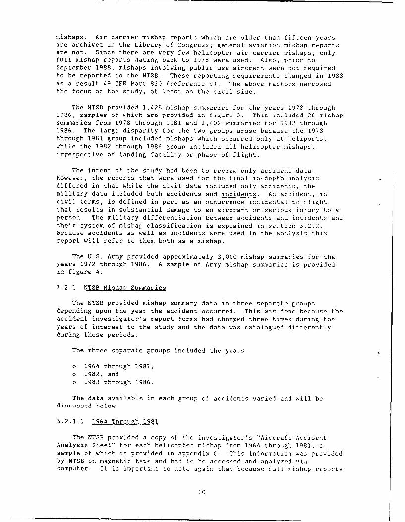
The U.S. Army provided approximately 3,000 mishap summaries for theyears 1972 through 1986. A sample of Army mishap summaries is providedin figure 4.
3.2.1 NTSB Mishap Summaries
The NTSB provided mishap summary data in three separate groupsdepending upon the year the accident occurred. This was done because theaccident investigator's report forms had changed three times during theyears of interest to the study and the data was catalogued differentlyduring these periods.
The three separate groups included the years:
o 1964 through 1981,o 1982, ando 1983 through 1986.
The data available in each group of accidents varied and will bediscussed below.
3.2.1.1 1964 Through 1981
The NTSB provided a copy of the investigator's "Aircraft AccidentAnalysis Sheet" for each helicopter mishap from 1964 through 1981, asample of which is provided in appendix C. This information was providedby NTSB on magnetic tape and had to be accessed and analyzed viacomputer. It is important to note again that because full mishap reports
10

The aircraft had just discharged two passengers on the rooftophelipad and was preparing for departure. The aircraft was picked upto a hover and the tailrotor struck a heliport surface perimeterlight. The tailrotor separated from the aircraft and the aircraftrotated to the right. Throttles were reduced to stop the rotationand the aircraft settled back down to the helipad. The aircraftbounced side to side and rolled off the helipad and came to rest onits left side. The pilot exited and extinguished a small fire thathad started near the engine exhaust.
While hovering from the wash rack, the helicopter backed into autility pole. The main rotor system separated from the airfranefollowing the collision. There were no postimpact mechanicalmalfunctions/failures.
During ground refueling of the aircraft the fuel tank was over-filledand the fuel spilled over onto the ramp. The fuel was ignited andthe aircraft was destroyed by fire.
The pilot was on a mission to transport company personnel and hadlanded on a barge that was being used as a helipad. The barde wasabout 250 feet long and 75 feet wide. After arriving, the pilotparked the helicopter with the tail boom as close to the edge of thebarge as possible. He then reduced the power to idle and signaledfor the three passengers (waiting behind a rope line) to approach thehelicopter in accordance with established procedures. As thepassengers approached the right side of the helicopter, they movedout of the pilot's line of sight. While two were boarding, the thirdpassenger walked to the rear of the aircraft, ducked under thehorizontal stabilizer and walked into the tail rotor. The victim wastaken to a hospital, but succumbed later due to head and shoulderinjuries. A training program had been instituted to educate thepassengers concerning hazards associated with rotating components ofthe rotor system and off-limit areas. The passenger had been briefedon three occasions and had been a passenger nearly every day for sixweeks.
Aircraft was parked with 3 feet clearance between main rotor andcorner of hangar. Pilot stated that on liftoff a gust of wind blewaircraft toward hangar. Main rotor blades made contact. Groundcrewman injured by flying debris.
The helicopter collided with a pole and landed hard during air taxito position the aircraft. The pilot had just off loaded passengersand was alone in the helicopter. A witness said the pilot hoveredtoo close to the pole and both rotor blades made contact. The polethat was struck was severed about 12 feet AGL.
FIGURE 3 NTSB MISHAP SUMMARIES
..
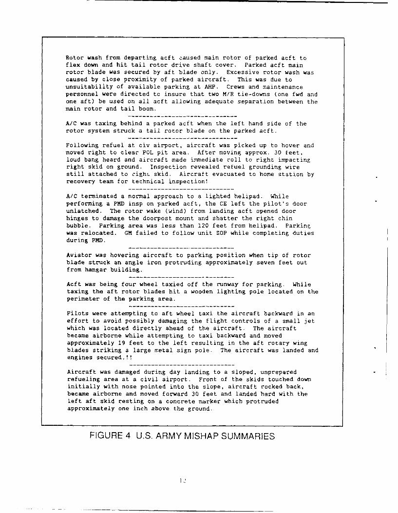
Rotor wash from departing acft eaused main rotor of parked acft toflex down and hit tail rotor drive shaft cover. Parked acft mainrotor blade was secured by aft blade only. Excessive rotor wash wascaused by close proximity of parked aircraft. This was due tounsuitability of available parking at AHP. Crews and maintenancepersonnel were directed to insure that two M/R tie-downs (one fwd andone aft) be used on all acft allowing adequate separation between themain rotor and tail boom.
A/C was taxing behind a parked acft when the left hand side of therotor system struck a tail rotor blade on the parked acft.
Following refuel at civ airport, aircraft was picked up to hover andmoved right to clear POL pit area. After moving approx. 30 feet,loud bang heard and aircraft made immediate roll to right impactingright skid on ground. Inspection revealed refuel grounding wirestill attached to righL skid. Aircraft evacuated to home station byrecovery team for technical inspection!
A/C terminated a normal approach to a lighted helipad. Whileperforming a PMD insp on parked acft, the CE left the pilot's doorunlatched. The rotor wake (wind) from landing acft opened doorhinges to damage the doorpost mount and shatter the right chinbubble. Parking area was less than 120 feet from helipad. Parkin;was relocated. GM failed to follow unit SOP while completing dutiesduring PHD.
Aviator was hovering aircraft to parking position when tip of rotorblade struck an angle iron protruding approximately seven feet outfrom hangar building.
Acft was being four wheel taxied off the runway for parking. Whiletaxing the aft rotor blades hit a wooden lighting pole located on theperimeter of the parking area.
Pilots were attempting to aft wheel taxi the aircraft backward in an
effort to avoid possibly damaging the flight controls of a small jetwhich was located directly ahead of the aircraft. The aircraftbecame airborne while attempting to taxi backward and movedapproximately 19 feet to the left resulting in the aft rotary wingblades striking a large metal sign pole. The aircraft was landed andengines secured.!!
Aircraft was damaged during day landing to a sloped, unpreparedrefueling area at a civil airport. Front of the skids touched downinitially with nose pointed into the slope, aircraft rocked back,became airborne and moved forward 30 feet and landed hard with theleft aft skid resting on a concrete marker which protrudedapproximately one inch above the ground.
FIGURE 4 U.S. ARMY MISHAP SUMMARIES
for mishaps prior to 1978 were not available, su'arIe. :c I .- pto 1978 were not considered. Mishap summaries for :shapr c--urt rigbetween 1978 and 1981 were r,.ct available on the macnetic ta; p7'cvided bythe NTSB, which necessitated a separate request for printed sufrrarie: forthat period. The NTSB provided a small number of mishap summaries forthe period of concern. This number included only those mishaps whichwere determined to have occurred at heliports. Since whether or not a
mishap occurred at a heliport could not always be determined from theinvestigator's report form or the mishap summary, it is not certain thatall of the heliport mishaps that occurred during this time pericd were
included in th.- mishap summaries provided by NTSB.
3.2.1.2 1982
The preliminary data obtained for the year 1982 were provided onmagnetic tape in three separate computer files. The files contained the
following dita for each accident:
o factual report,o mishap summary. and
o cause and factors listing.
A sample of the investigator's report form is presented inappendix D. This was basically "fill in the blanks" type information.Information provided in the report form includes date, time, and locationof the mishap, as well as items concerning the aircraft, pilot,
passengers, and selected information relevant to the mishap.
The mishap summary file is a narrative file that contains a briefsummary of each mishap. These summaries were similar to those presentedin figure 3. The 1982 mishaps for which full mishap reports were orderedwere selected primarily based upon these summaries.
The cause and factors file contained data concerning the principaland contributing cause and factors for each mishap. This file was
relative to the design issues under study.
As previously mentioned, all three files for each mishap wereprovided on magnetic tape. These files were downloaded onto 5 1/4"floppy disks for use on personal computers. Computer programs were thenwritten to retrieve the desired information.
3.2.1.3 1983 Through 1986
Data provided by the NTSB for these years were again presented inthree separate files on magnetic tape. These data were very similar tothat provided for 1982; however, the investigator's report form used from1983 through 1986 differed from that used in 1982 (see appendix E). Asin the case of the 1982 data set, full mishap reports were ordered basedprimarily upon the mishap summary files.
3.2.2 Military Mishap Summaries
A written request for U.S. Army mishap information was made to theU.S. Army Safety Center at Fort Rucker, Alabama. Fort Rucker is theprimary repository for Army aviation mishap reports and statistics.
13
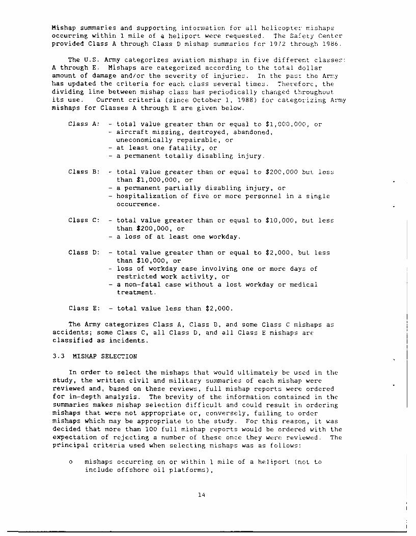
Mishap summaries and supporting information for all helicopter mishapsoccurring within 1 mile of a heliport were requested. The Safety Centerprovided Class A through Class D mishap summaries for 1972 through 1986.
The U.S. Army categorizes aviation mishaps in five different classes:A through E. Mishaps are categorized according to the total dollaramount of damage and/or the severity of injuries. In the past the Armyhas updated the criteria for each class several times. Therefore, thedividing line between mishap class has periodically changed throughoutits use. Current criteria (since October 1, 1988) for categorizing Armymishaps for Classes A through E are given below.
Class A: - total value greater than or equal to $1,000,000, or- aircraft missing, destroyed, abandoned,uneconomically repairable, or
- at least one fatality, or- a permanent totally disabling injury.
Class B: - total value greater than or equal to $200,000 bui, lessthan $1,000,000, or
- a permanent partially disabling injury, or- hospitalization of five or more personnel in a single
occurrence.
Class C: - total value greater than or equal to $10,000, but lessthan $200,000, or
- a loss of at least one workday.
Class D: - total value greater than or equal to $2,000, but lessthan $10,000, or
- loss of workday case involving one or more days ofrestricted work activity, or
- a non-fatal case without a lost workday or medicaltreatment.
Class E: - total value less than $2,000.
The Army categorizes Class A, Class B, and some Class C mishaps asaccidents; some Class C, all Class D, and all Class E mishaps areclassified as incidents.
3.3 MISHAP SELECTION
In order to select the mishaps that would ultimately be used in thestudy, the written civil and military summaries of each mishap werereviewed and, based on these reviews, full mishap reports were orderedfor in-depth analysis. The brevity of the information contained in thesummaries makes mishap selection difficult and could result in orderingmishaps that were not appropriate or, conversely, failing to ordermishaps which may be appropriate to the study. For this reason, it wasdecided that more than 100 full mishap reports would be ordered with theexpectation of rejecting a number of these once they were reviewed. Theprincipal criteria used when selecting mishaps was as follows:
0 mishaps occurring on or within 1 mile of a heliport (not toinclude offshore oil platforms),
14
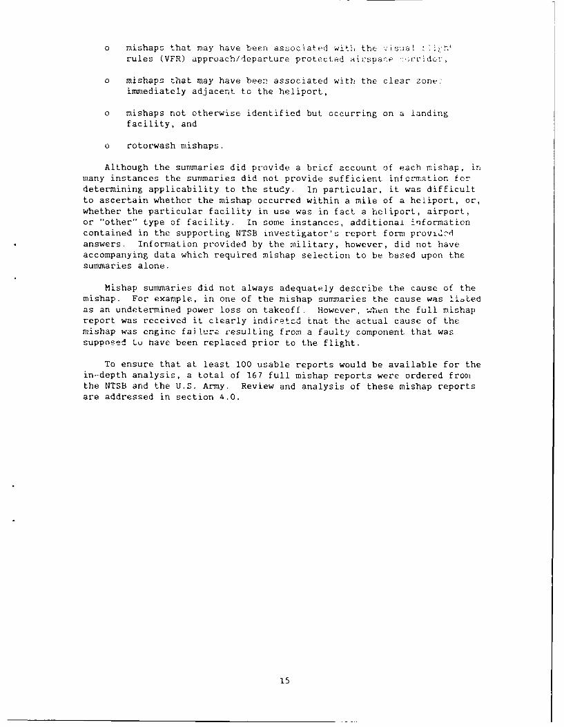
o mishaps that may have been associated witli the v suaL [1i t'rules (VFR) approach/departure protected airspace ':,rridcr.
o mishaps that may have been associated with the clear zone-immediately adjacent to the heliport,
o mishaps not otherwise identified but occurring on a landing
facility, and
o rotorwash mishaps.
Although the summaries did provide a brief account of each mishap, inmany instances the summaries did not provide sufficient information fordetermining applicability to the study. In particular, it was difficultto ascertain whether the mishap occurred within a mile of a heliport, or,whether the particular facility in use was in fact a heliport, airport,or "other" type of facility. In some instances, additionai informationcontained in the supporting NTSB investigator's report form provld.>
answers. Information provided by the military, however, did not haveaccompanying data which required mishap selection to be based upon thesummaries alone.
Mishap summaries did not always adequately describe the cause of themishap. For example, in one of the mishap summaries the cause was It.Ledas an undetermined power loss on takeoff. However, ;;hen the full mishapreport was received it clearly indicatcd tnat the actual cause of themishap was engine fai lure resulting from a faulty component that wassupposed to nave been replaced prior to the flight.
To ensure that at least 100 usable reports would be available for thein-depth analysis, a total of 167 full mishap reports were ordered fromthe NTSB and the U.S. Army. Review and analysis of these mishap reportsare addressed in section 4.0.
15
4.0 IN-DEPTH ANALYSIS
The in-depth analysis consisted of analyzi,.,' civi- .cmishap reports. Cf primary importance in analyzing thus, _understanding facility design factors which contributed t , otindividual mishap. Therefore, to a great extent the results.conclusions, and subsequent recomtiendations fct this study n:.ged spc'cthe quantity and quality of information contained in the :ull mishar;reports. The information contained in these reports deptr d:- upon sevor-factors. For instance, the type of operation in which thu aircraft wasinvolved at the time of the mishap may determine the extent of the .kshu_investigation and thereby the completeness of the final mishap repor:.Air carrier mishaps arc typically the most intensely investigatedcivilian mishaps. Consequently, air carrier mishap reports are usuallythe most comprehensive, containing more details and information thannon-air carrier reports. Additional factors which may affect the as.ouritof information in a mishap report include the skill and experienci of thton-site investigator/tea, the severity of the mishap in terms of injuryand property damage, and the availability of survivors and/or witnesses.
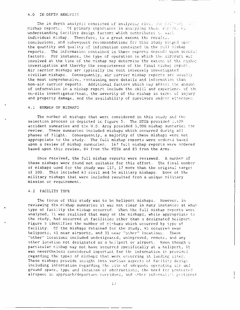
4.1 NUMBER OF MISHAPS
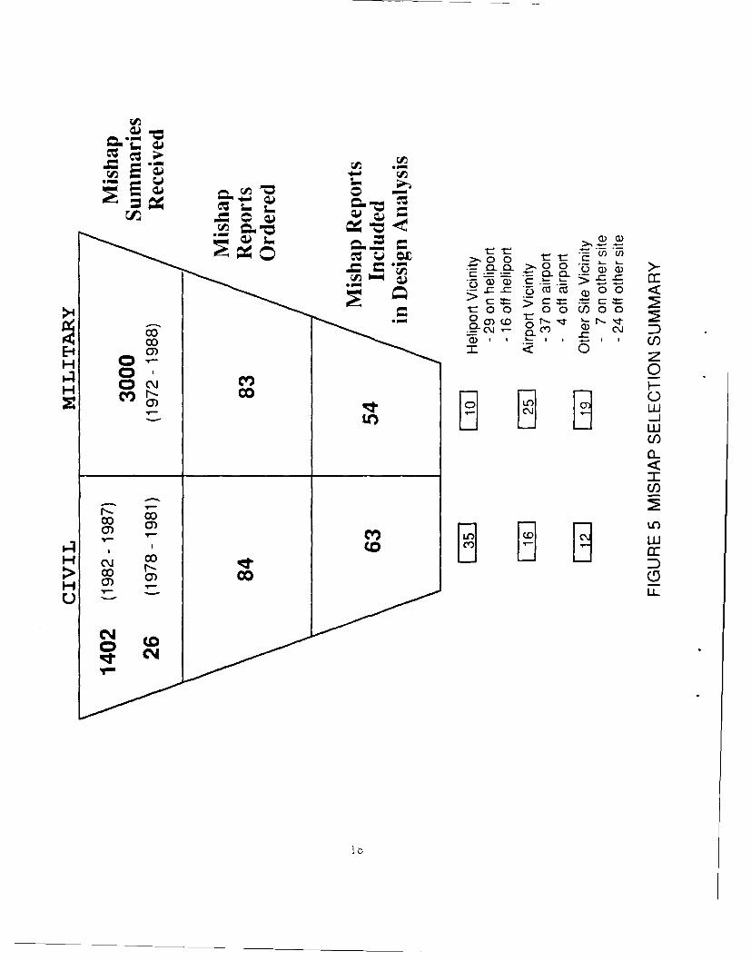
The number of mishaps that were considered in this study and tlrie,selection process is depicted in figure 5. The N1TSB provided 1,428accident summaries and the U.S. Army provided 3,000 mishap sumtaries torreview. These summaries included mishaps which occurred during allphases of flight. Consequently, a majority of these mishaps were notappropriate to the study. The full mishap reports were ordered basedupon a review of mishap summaries. 167 full mishap reports were orderedbased upon this review, 84 from the NTSB and 83 from the Army.
Once received, the full mishap reports were reviewed. A number ofthese mishaps were found not suitable for this effort. The final numberof mishaps used for the study was 117, 17 more than the original targetof 100. This included 63 civil and 54 military mishaps. Norie of themilitary mishaps that were included resulted from a unique militarymission or requirement.
4.2 FACILITY TYPE
The focus of this study was to be heliport mishaps. However, inreviewing the mishap summaries it was not clear in many instances at whattype of facility the mishap occurred. When the full mishap reports wereanalyzed, it was realized that many of the mishaps, while appropriate tothe study, had occurred at facilities other than a designated heliport.Figure 5 identifies the number of ri-haps which occurred by type offacility. Of the mishaps retained for the study, 45 occurred nearheliports, 41 near airports, and 31 near "other" locations. These"other" locations included undesignated, unimproved, remote, and anyother location not designated as a hiliport or airport. Even though aparticular m[ishap may not have occurred specifically at a heliport, itwas nevertheless considered important for the information it provid.dregarding the types of mishaps that were occurring at landinF, site.These mishaps provide insight into various aspects of facility desigsincluding information regarding the: size ot adequatc operatii:, ai- arndground space, type and location of obstructions, the need for prot' ctfdairspace ir. approach/departure corridor:s, and ot her jform!ati. prtinert
1/
rA~
Z -:
C13CZ Q) 0
V-0 0. >00 -) 0- 0
0 tfa) (DJ 0
0 0- z
H 4. r-no LLUI__j
LI
C/)
H ~j coD
(DHU U-
Nl
to helipnrt design. in many instance:; J7 pe70 ' tre :v,- - -the in-depth analysis occurred at landing :its ia : ,,stringent dt3ign standards than the.-;e providrd i, he 'AC. This finding suggests that a nur,ber of these 2jshdpoccurred had the Heliport Design AC design standard: beer -',f: Ithese locations.
4.3 DESIRED DETAILS
Although all aspects of heliport design were .:onsidered, >su'
associated with dimensions specifically addressed in the li* ,c- DesignAC were of primary importance. Specific areaS in whitch ditailclinformation was desired are addressed below.
The size of parking spaces, taxiways, and refueling area- 1.1 r
considered highly important and deserving of particular at,- C11,of the single most important aspects of this study was hJ 4- tairspace. This not only included the protected airspace :u'--' ~ $ ig
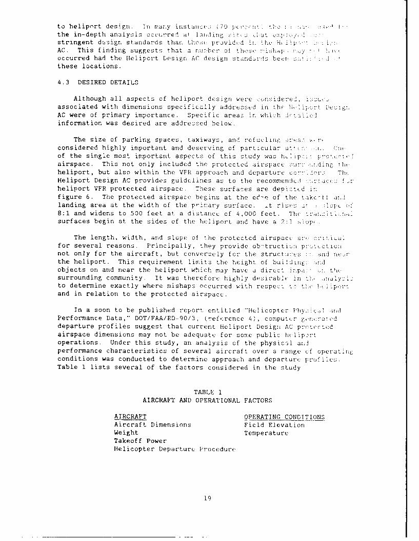
heliport, but also within the VFR approach and departure c:'T--n_!- 711.Heliport Design AC provides guidelines as to the recommended cccheliport VFR protected airspace. These surfaces are deoict .dfigure 6. The protected airspace begins at the ed'-e of the take tt a:,]landing area at the width of the pw-irary surface. _t risen .cit C,
8:1 and widens to 500 feet at a distance of 4,000 feet. Th rsurfaces begin at the sides of the heliport and have a 2:1 . op
The length, width, and slope of the protectcd airspace are. cr,:icfor several reasons. Principally, they provide obctructin:: pn'ettctiolinot only for the aircraft, but conversuly for the structu-e z, s :. and nedir"the heliport. This requirement limits the height of bui/dir.: .,dobjects on and near the heliport which may have a direct ipci <:. the.surrounding community. It was therefore highly desirable in th. -nalyzi:to determine exactly where mishaps occurred with respect _: t.i -and in relation to the protected airspace.
In a soon to be published report entitled "Helicopter Phycical andPerformance Data," DOT/FAA/RD-90/3, (reference 4), computcr gervraneddeparture profiles suggest that current Heliport Design AC protectedairspace dimensions may not be adequate for some public h liportoperations. Under this study, an analysis of the physical andperformance characteristics of several aircraft over a range of operatingconditions was conducted to determine approach and departure profiles.Table 1 lists several of the factors considered in the study
TABLE 1AIRCRAFT AND OPERATIONAL FACTORS
AIRCRAFT OPERATING CONDITIONSAircraft Dimensions Field Elevation
Weight TemperatureTakeoff PowerHelicopter Departure Procedure
19
500'0 (15 m
/7,r M-
N-TH /7F RRGT- VI
_6 M) /BETO OS SNIIEAF
TH RItR SRAE SPiYIAV',
/ZETC. /CTETKCFA1
/ .NI;: RA
FIGUE 6V ELIORT ROTCTEDMA IRSPDECE SURFCE
TH10 TCRRGTTOASI
Using the information in table 1, manufacturer pulli nnsl data, and acomputer simulation model, approach and departure protiles tw7 severaLhelicopter models were generated. These profiles illustrated that undersome conditions, the 8:1 slope described in the Heliport Design AC may beinadequate. This is especiilly true for -high,' hotj and "heavy"operations, in which aircraft typically have poorer performance.
It was hoped that critical information such as exact location of amishap with respect to the heliport, especially for mishaps that occucred
off the facility, could be obtained from the mishap reports. ininstances of wire strikes, the height and distance at which the aircraftstruck the wire. in relation to the heliport, was critical to determiningwhether or not the aircraft was operating within the reconsendedprotected wirspnce. Also, forced landings on takeoff mishaps were ofgreat interest, since in some instances they may result in the helicopterdropping below the 8:1 slope. These mishaps included mechanicn! ormaterial failures, other emergencies, and set~ling due to insu:tientpower for the operating conditions.
4.4 MISHAP SUMMARY FORM
A mishap summary form (figure 7) was developed to assist in theanalysis. This was done in order to collate and standardize as Tuch datecontained in the reports as possible. This standardization assisted inthe overai" analysis, descriptie results, and conclusions of th study.Vhile many of the items included on the mishap summary fort wey- genezadetails for each mishap, they were deeme! important from : trernperspective in the in-depth analysis. Specific items such as time ofyear, time of day, location, amount of daylight, prevailing weather,etc., when considerod for the entire data set, could indicatL 'c toanpatterns which were not otherwise apparent when considering cart, misharseparately. Therefore, the in-depth analysis not only focused uponspecific design issues, but also included a total overview apprcwK Q,ensure detection of trends that may not be discernable when considerim,each mishap separaLely Three specific categories that were included onthe mishap summary form, and upon which the results of this task arebased were:
o facility mishap location,o -,ishap type, and
a heliport design issues.
4.4.1 Facility Mishap Location
During preliminary stages of the study and later while reviewingmishap summaries, it became apparent that sont method of groupinp themishaps was highly desirable. It was decided that the location where th-mishap occurred would serve as a good hight. level category for groupiigthe mishaps. Table 2 contains the various categories in which themishaps were arranged according to location.
TABLE 'FACILITY MIS HAP LOCAT 'OP
TAXIWAY APPROACH AIRSPA:EPARKING AREA APPROACH GROUNDSPACLREFUELING AREA LFARTUPE AIRSPACEFINAL APPROACH ANPL LA OF. AREA 7EiARTUR E (RDsYP 2PACF,

'.IISHAP LOCATION
OCCURRENCE INFORMATION LOCATION LOCATION TY'PENO0 DATE DAY TIME CITY STATE ELEVATION HELIPORT AIRPORT OTHER
H. A 0.
MAISHAP TvD=E Root Cause Relateo Cause:: =Piot IDM=Decision MaKinc.A=Aircratt (M=Mecnanica;E=nvirolment IW=Wino,O=Ooeratioi P=Proceoures
FLIGH- 2pEA TO OPERATING -ELIPORT DESIGIN IS SUES
0 L CL; CEILING .SLI" WIND WNIND GU;STS CNNDC LOWEST LOWEST RO S PE EDC AT iTUC;E
~T A TAGL S1.1 'IAG KTS K T
FIG1PC 7 MISHAP SUMMARY FORM
4.4.2 Mishap Type
The mishap type represents what occurred during each mishap. Thosemishaps selected for analysis fell into the following categories:
obstruction strikes (on-facility) collision with other aircraftobstruction strikes (off-facility) insufficient climb anglepower loss on takeoff power loss on approachrotorwash stuck skidswind indication refueling
4.4.3 Heliport Design Issues
One purpose of this study was to understand the manner in whichheliport design may contribute to helicopter mishaps. Eachmishapconsidered in the in-depth analysis was selected based upon itsrelationship to a heliport design factor. Heliport design issuesidentified during the analysis are included in the results section of thereport and suggest the basis for the conclusions and recor'mendationspresented.
4.5 NTSB MISHAP REPORTS
The NTSB mishap reports varied in both length and content dependingupon factors previously mentioned. Even though specific dimensionaldetails, such as the exact location of an obstruction with respect to thetakeoff/landing area were usually not available, the reports did help toidentify design factors which contributed to facility mishaps. Thereports provided an adequate description of the causes and factors ofeach mishap, thereby providing insights as to the manner in whiclheliport. design might be a contributor to facility mishaps.
4.6 U.S. ARMY MISHAP REPORTS
The Army mishap reports also varied in both length and content formany of the same reasons as the NTSB reports. The mishap reoorts forClass A, Class B, and some Class C mishaps varied in length fro. 2b toover 100 pages and contained substantial amounts of inforTiition. Thremaining Class C and all Class D reports were typically brief (I to ]bpages) and did not contain the extensive details o the Class A and B
reports.
Table 3 provides a summary of the Army mishaps u.-1- for thti in-depthanalysis by class. It is interesting to note that the majority offacility mishaps occurred in a class (Class D) that repreoent2 r i t~vdysmall monetary losses. However, thes,: mishap:- are import;lrit inunderstanding potential facility design related shortfoll.> Thi.observation highlights the need for adequate documenitatin,, !.: rt:.
accidents and incidents in order to support, safety studi ur: z,. I. ',, in.individual mishap may not appear to be- r-elated] to h', 1iprr ,:: sn.seemingly minor contributing factor:: ,may provt L,, b. i ',considered collectively with other mishap:;.
2 1
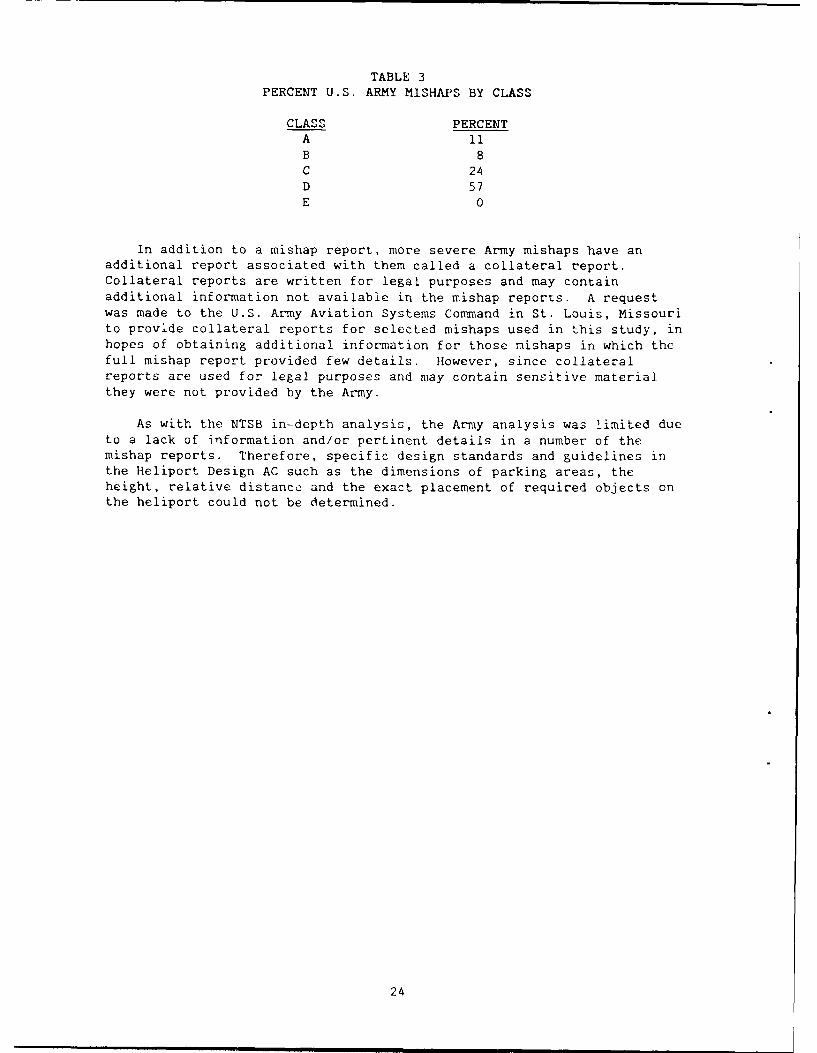
TABLE 3PERCENT U.S. ARMY MISHAPS BY CLASS
CLASS PERCENTA 11B 8C 24D 57E 0
in addition to a mishap report, more severe Army mishaps have anadditional report associated with them called a collateral report.Collateral reports are written for legal purposes and may containadditional information not available in the mishap reports. A requestwas made to the U.S. Army Aviation Systems Command in St. Louis, Missourito provide collateral reports for selected mishaps used in this study, inhopes of obtaining additional information for those mishaps in which thefull mishap report provided few details. However, since collateralreports are used for legal purposes and may contain sensitive materialthey were not provided by the Army.
As with the NTSB in-depth analysis, the Army analysis was limited dueto a lack of information and/or pertinent details in a number of themishap reports. Therefore, specific design standards and guidelines inthe Heliport Design AC such as the dimensions of parking areas, theheight, relative distance- and the exact placement of required objects onthe heliport could not be determined.
24
5.0 RESULTS
Analysis of the available data from the NTSB and U.S. Army mishapreports highlighted possible heliport design issues which may need to beaddressed, expanded, or emphasized in the Heliport Design AdvisoryCircular. In addition to heliport design issues, the in-depth analysisbrought forth several operational issues that contributed in asignificant way to several of the mishaps in this study. Since theseoperational issues contributed to heliport mishaps they will be discussedfurther in section 5.3. Conclusions and recommendations are presented insection 6.0
5.1 GENERAL FACTORS
Each mishap report contained general information sirh as date, time,geographic location, elevation, operating conditicn. (i.e. visual orinstrument conditions), and mission type, along with information specificto the mishap. This general informati:., was analyzed to deter-.in if anyof these factors pointed to a trend in a significant number of mishaps.After review, it was determined that the time of year, timE of day,geographic location, fi..Id elevation, operating condition,, and missiontype appeared to bave had little influence on the group as a whole. Ingeneral, the ,,,ishaps occurred to a variety of helicopter, operatorsthroughout the year, randcmly throughout the day, over a rangL of densityal itudes, and across the entire united States. While some cf the6eneral factors may have influenced individual mishaps or even severalmishaps, no one factor played a major role in the mishaps. Individualmishap analysis yielded the findings as described in the followingparagraphs.
5.1.1 Mishap Locations
It was particularly important to understand where, with respect tothe facility, mishaps occurred. That is, did the mishap occur in theparking area, the refueling area, on approach or departure, or at someother location on the facility. The location of the mishaps with respectto the facility are presented in figure 8. It is interesting to notethat the largest percentage of mishaps occurred in the departure area.This included both departure airspace (e.g. wire strikes) and departuregroundspace (e.g. power loss on takeoff) mishaps. The second mostfrequent location for mishaps was in the parkitig area. As will be showMnlater, a large portion of these mishaps occurred at airports. Also ofnote in figure 8 is that the majority of mishaps that occurred in th(approach or departure area occurred off the facility.
As indicated in figure 8, helicopter mishaps may occur anywhere onthe facility. Although some locations appear to have a significantlylarger portion of the mishaps, no location at a facility appears immune.
5.1.2 Mishap Types
To understand potential design issues, it is necessary to recognizethe types of mishaps that are occurring at various facilities. Becauscof the large number of mishaps used in this analysis, most of the type:of mishaps that may occur at heliports are included. It is interestingto note that several of these types of mishaps occur significantly morfoften than others. This proclivity is. the result of sevral factors,some of which may or may not be related to heliport design.
25

a, Z)
t, M~
C-
M
C c0C z
cz 0
0-0 -<
C)
< -J
Q) _
LL
ow c
LO C LO) C0L
2h
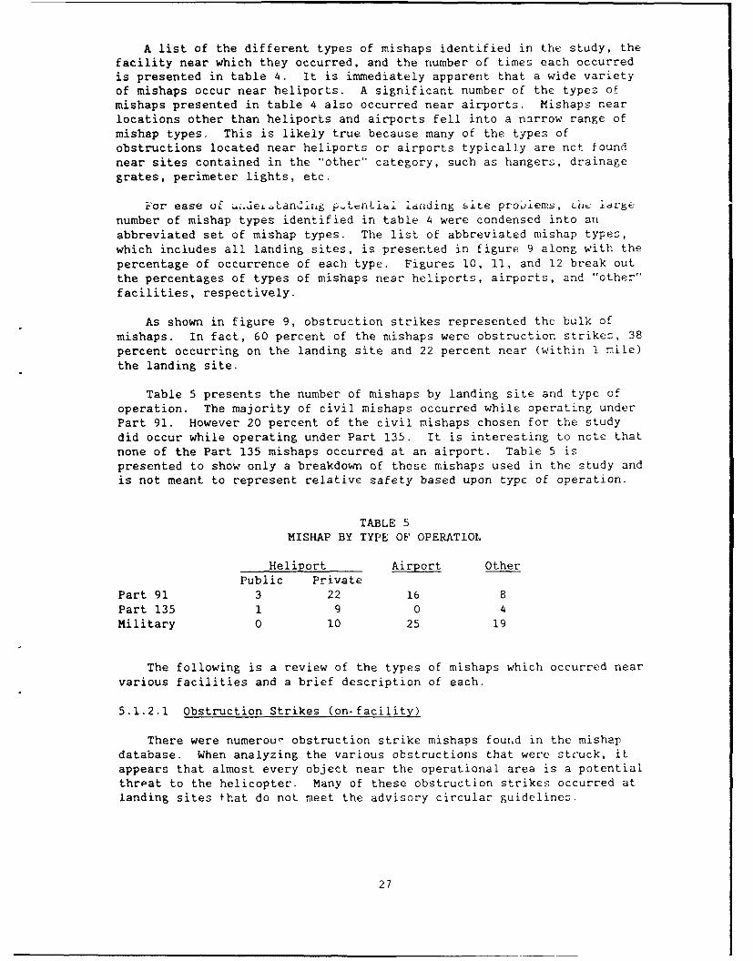
A list of the different types of mishaps identified in the study, thefacility near which they occurred, and the number of times each occurredis presented in table 4. It is immediately apparent that a wide varietyof mishaps occur near heliporLs. A significant number of the types ofmishaps presented in table 4 also occurred near airports. Mishaps nearlocations other than heliports and airports fell into a narrow range ofmishap types. This is likely true because many of the types ofobstructions located near heliports or airports typically are not foundnear sites contained in the "other" category, such as hangers, drainagegrates, perimeter lights, etc.
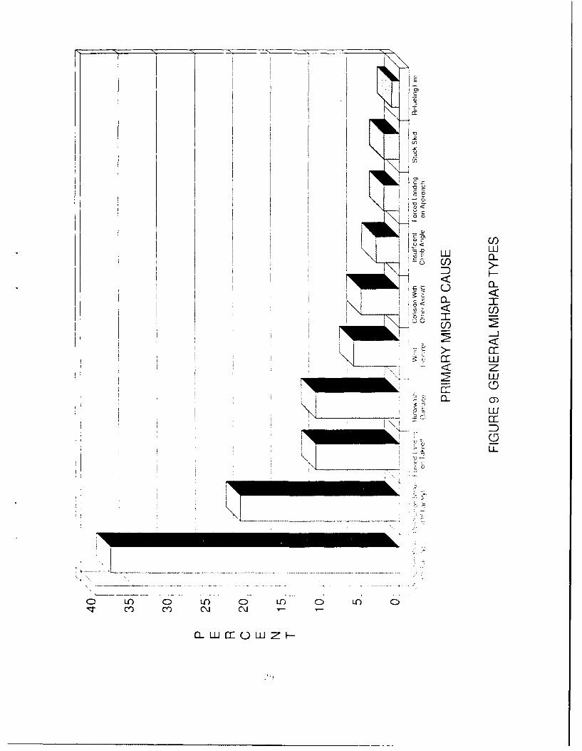
ror ease of pteLLandi.,g t-nLiai landing site probiems, Lil idl5e
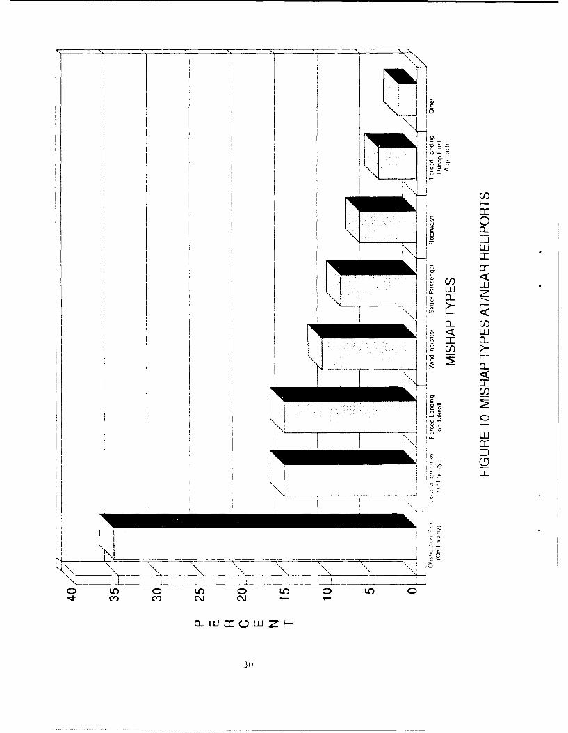
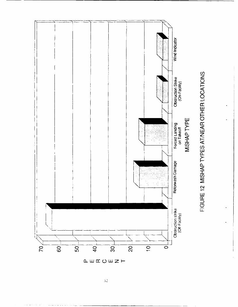
number of mishap types identified in table 4 were condensed into anabbreviated set of mishap types. The list of abbreviated mishap types,which includes all landing sites, is presented in figure 9 along with the
percentage of occurrence of each type. Figures 10, 11, and 12 break outthe percentages of types of mishaps near heliports, airports, and "other"facilities, respectively.
As shown in figure 9, obstruction strikes represented the bulk ofmishaps. In fact, 60 percent of the mishaps were obstruction strikes, 38percent occurring on the landing site and 22 percent near (within 1 mile)the landing site.
Table 5 presents the number of mishaps by landing site and type ofoperation. The majority of civil mishaps occurred while operating underPart 91. However 20 percent of the civil mishaps chosen for the studydid occur while operating under Part 135. It is interesting to nete thatnone of the Part 135 mishaps occurred at an airport. Table 5 ispresented to show only a breakdown of those mishaps used in the study andis not meant to represent relative safety based upon type of operation.
TABLE 5MISHAP BY TYPE OF OPERATIOL
Heliport Airport OtherPublic Private
Part 91 3 22 16 8Part 135 1 9 0 4Military 0 10 25 19
The following is a review of the types of mishaps which occurred nearvarious facilities and a brief description of each.
5.1.2.1 Obstruction Strikes (on-facility)
There were numerous obstruction strike mishaps found in the mishapdatabase. When analyzing the various obstructions that were struck, itappears that almost every object near the operational area is a potentialthroat to the helicopter. Many of these obstruction strikes occurred atlanding sites that do not meet the advisory circular guidelines.
27
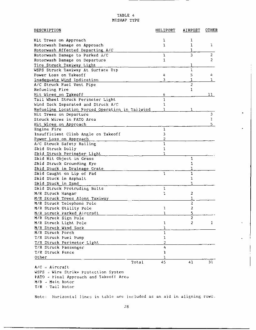
TABLE 4
MISHAP TYPE
DESCRIPTION HELIPORT AIRPORT OTHER
Hit Trees on Approach 1 1Rotorwash Damage on Approach 1 1 1Rotorwash Affected Departing A/C 1
Rotorwash Damage to Parked A/C 1 3 2
Rotorwash Damage on Departure 1 2
Tire Struck Taxiway Light 1WSPS Struck Taxiway At Surface Dip i
Power Loss on Takeoff 4 5 4
Inadequate Wind Indication 3 1 1A/C Struck Fuel Vent Pipe 2Refueling Fire 1
Hit Wires on Takeoff 6 11Tail Wheel Struck Perimeter Light 1
Wind Sock Separated and Struck A/C 1Refueling Location Forced Operation in Tailwind 1 1Hit Trees on Departure 3Struck Wires in FATO Area 1
Hit Wires on Approach 5Engine Fire 1Insufficient Climb Angle on Takeoff 3
Power Loss on Approach 2A/C Struck Safety Railing 1
Skid Struck Dolly 1Skid Struck Perimeter Light 1Skid Hit Object in Grass 1Skid Struck Grounding Eye 1
Skid Stuck in Drainage Grate 1Skid Caught on Lip of Pad 1 1
Skid Stuck in Asphalt 1
Skid Stuck in Sand 1Skid Struck Protruding Bolts 1
M/R Struck Hangar 1 2M/R Struck Trees Along Taxiway 1M/R Struck Telephone Pole 2
M/R Struck Utility Pole 1 2H/R Struck Parked Aircraft 1 5M/R Struck Sign Pole 2
M/R Struck Light Pole 1 2 1M/R Struck Wind Sock 1M/R Struck Porch I
T/R Struck Fuel Pump 1
T/R Struck Perimeter Light 2T/R Struck Passenger 4
T/R Struck Fence 1Other 1
Total 45 41 31A/C =Aircraft
WSPS Wire Strike Protection SystemFATO Final Approach and Takeoff Area
M/R = Main RotorT/R Tail Rotor
Note: lorizontal lines in table are included as an aid in aligning rows.
28
cILI
D CD
76 LL
--- - -- . . . . .. -- - -- ---
0 Lr) C) L 0 L 0uLIZT CY ce) ~C l)
a_ LL Cc ( LL-
I CiI
2 UH j I D
C 0C-
o LO C0 LO CD O 0 LO 04:TCY) C') N NT--J
aOWmowzH
30

CIl)
crH<
I LU
LU
I~ m5
C) CUC-C))C
wI-O I-I-CV)-I
0
C/)z0
C-)0
.0
LU I<
cu 0)LL
x 0- z90 <
0o- C/)LU,
0)~
CU)
C/)
LU
i D
3-15

However, there are lessons to be learned by looking at these mishaps.The items that were struck at landing sites include the following:
taxiway light telephone poleperimeter light sign polewind sock utility polehangar light polevent pipe (fuel pump) taxiway (dip in taxiway)trees (near taxiway) helipad lip (raised helipad)grounding eye guy wire
safety railing (rooftop) drainage gratefuel pump parking dollypersonnel protruding bolt (rooftop)safety fence
From the above list, several observations can be made. The need forrelatively flat/clean operating surfaces is confirmed by the mishapdatabase which shows that helicopter skids caught on a variety ofobjects, such as a protruding bolt, the helipad lip, grounding eye, and adrainage grate. A dip in the taxiway caused a wire strike protectionsystem (WSPS) to strike the ground during a wheeled taxi. 1n addition,loose dirt and snow were responsible "or brownout and whiteout conditions..hich resulted in obstruction strike mishaps.
Large objects which were struck such as hangars, light poles, signpoles, etc. highlight the difficulty in judging clearances from objects.Several of the mishaps occurred despite using a ground marshal to assistin the movement of the aircraft. These mishaps are a clear indicationthat judging obstruction clearances may be a difficult task. The largenumber of obstruction mishaps also implies that operational areas are toosmall at some heliports.
Another interesting observation is that objects designed specificallyfor safety purposes are not themselves immune from mishaps. Objects suchas safety fences, railings, grounding eyes, and wind socks were involvedin several helicopter mishaps. Finally, personnel strikes refer topassengers walking into turning tail rotors. Unfortunately, some ofthese accidents occurred even when passengers had been thoroughly briefedon safety procedures.
5.1.2.2 Obstruction Strikes (off--facility)
Obstruction strikes that occur near landing sites indicate the needfor adequate clear space in which to operate helicopters. The kinds ofobstructions that were struck near landing sites include the following:
telephone wires,
guy wires,power lines,noise berms, and
trees.
While there were a number of obstruction strikes near landing sites,the number of different types of objects that were struck was limitedwhen compared to on--facility strikes. The mishaps occurring near landing
33
sites occurred during both approach and departure. As noted earlier, sheoff-facility mishaps were important from a protected airspace designaspect. Unfortunately, the majority of these mishap reports did riotcontain detailed information as to where the obstructions were withrespect to the landin; site. However, in _as~s of wire strikes, thepilot did not see the wire in sufficient time to prevent the wire strike.
5.1.2.3 Forced Landings on Takeoff
This group of mishaps i-.volved the need to immediately land theaircraft during the takeoff or initial climbout. They occurred forseveral reasons including, mechanical or material failure, otheremergencies, and insufficient power for the operating conditions. Thesemishaps hi6hlight the benefits of providing as much operating space a-possible and/or practical.
5.1.2.4 Rotorwash Damage
Rotorwash damage occurred primarily during approach drid departure.These mishaps usually involved damage to parked vehicle: under or nearthe operating area. In one extreme case, rotorwash caused a woman tofall and break her leg. In another instance, the rotorwash from ahovering helicopter, holding at an intersection, destroyed the groundeffect of a helicopter attempting to take off. Rotorwash also causeddamage to parked aircraft. All of the rotorwash mishaps used in thisstudy were associated with military operations. However, they occurredat both civil and military facilities.
5.1.2.5 Wind Indication
Several mishaps occurred due to the influence of the wind onrotorcraft operations. Most of these mishaps involved operations inunexpected wind conditions. It appears in these mishaps that the pilotmay have been unaware, or, may have been misled about the actual windconditions during the operation. One instance involved operating next toa row of hangars. The hangars obstructed the wind nearby. Upon depart-ing the area the helicopter encountered a strong tailwind and downdraftresulting in the helicopter crash. Another instance involved a helicopter operating next to a hospital. As the helicopter flew around thebuilding it encountered wind conditions which, according to the pilot,causeO the vertical speed indicator to register an increase in descentrate of nearly 3,000 feet per minute. In both instances the altering ofthe prevailing wind by the buildings appears to hate contributed to th(.mishaps. In these instances, wind information available to the pilot atthe facility did not adequately represent the actual operating conditions. Reference 6 addresses the subject of wind flow near structures.
In addition to availability, placement of the wind sock is alscritical, not only to provide an accurate wind indication, but alt; tcz:safety of operations. One helicopter struck a wind sock whiie operoton the heliport, while in another case the wind :coc:k was separited fz <its mounting by rotorwash and struck the ma;i rotor.
5.1.2.6 Collision with Other Aircraft
There were several instance; of or 1rour3 ci isi on 1),twoeraircraft. These. collis ion:: occurred in pairk n areas and us: 'Ilyinvolved a parked aircraft being struck by Lil aircraft tryirn) ', ",lrfUVo"
14
in the parking area. Here again, as in the case of obstruction -trikes,judging clearances from turning rotor blades proved difficult. Twoseparate mishaps occurred when both aircraft were parked. While oneaircraft w-s standing with rotors turning, an adjacent aircraft beganturning rotors with inadequate spacing between rotor systens.
5.1.2.7 Insufficient Climb Angle
These mishaps occurred on departure immediately after takeoff.Insufficient climb angle mishaps occur for several reasons, such asfailing to compensate for high density altitudes or encountering anunexpected tailwind while operating at maximum performance limits. Inall cases, the aircraft was unable to sustain flight and impacted ',heground. These mishaps indicate the need to provide clear groundspace andthe need for the pilot to fully understard the operating environment an]operating limitations of the aircraft.
5.1.2.8 Forced Landing During Final Approach
These mishaps involved a loss of power or any other reason requiringsubsequent forced landing Curing final approach. As in tha case offorced landing on takeoff, they indicate the benefit of providing cleargroundspace underlying the approach corridor
5.1.2.9 Stuck Landing Gear
These mishaps occurred because the operating surface was inadequateto support the weight of the aircraft. Examples include a helicopterwhich attempted to lift off with a skid stuck in asphalt and another witha skid stuck in soft sand. Both aircraft rolled over as they attemptedto lift off. The mishap involving the aircraft with the skid stuck inasphalt highlights the importance of designing a surface capable ofsupporting the aircraft under all operating conditions. For instance,concrete may be preferrable to asphalt, particularly in areas which mayexperience extremely warm temperatures. In these locations skids maymake indentations in asphalt surfaces which can present a hazard tooperations. Helicopters with wheeled landing gear are also prone to thistype of problem.
5.1.2.10 Refueling Fire
Although there was only one refuelin2 fire mishap used in the study,it did point to the need for constart vigilance during refuelingoperations. ,n th.s particular mishap the helicopter was being refueledafter having been shut down. However, the cooling fan was left running.During the refueling the helicopter was left unattended. The automaticshutoff on the refueling nozzle failed, and a fuel spill occurred. Thefuel subsequently ifnited and the helicopter was destroyed.
5.2 DESIGN ISSUES
This section addresses the design issues which may have contributedto the mishaps considered in this study. The intent is to gain an under-standing of the manner in which current hliport design standL-dr maycontribute to "'ishaps, to identify any needed changes, and to formulaterecommendations in order to provide a safer cperating environment forhelicopters.
3 b
The design issues identified in this study and the percenztage ofmishaps related to each are shown in figure 13. Thec'e were severaldesign issues which were pertinent to the majority of the mishaps.Following is a discussion of each design issue and examples of how itapplies to the mishap database.
5.2.1 Approach/Departure Obstruction Marking/Clearance (21.4 percent.of mishaps)
Wire strikes in both the approach and departure phases of flightrepresent the majority of mishaps for this group. Unfortunately, due tothe lack of detail in the majority of these mishap reports, it wasimpossible to d-termine the exact location of the wires with respect tothe landing site. In the two reports that did contain information as tothe location of the wires, the wires were located within the 8:1protected airspace surface. This indicates that the approach/departureairspace did not meet the advisory circular criteria for public heliports.
In all of these wire strike mishaps the wires were not marked withobstruction markers and the pilots failed to see the wires in time toavoid them. This subset of mishaps highlights the need for facilityoperators to insure that obstructions, especially wires, which lie in theapproach/departure corridors are marked and identified. in mostinstanzes State and Local authorities will assist operators in markingobstructions.
In addition to wire strikes, there were several obstruction strikesinvolving trees. These strikes occurred on departure. Here too, themishap reports lacked specific details as to the location of the treeswith respect to the final approach and takeoff area (FATO). However,from the report descriptions it can be said that the pilot did know thetrees were present prior to beginning the takeoff procedure. Thesemishaps point out the need for adequate clearance on departure. Thisdesign issue is coupled with a related operational/human factors issue ofthe pilot knowing and observing the performance capabilities/limits ofthe aircraft under the prevailing environmental conditions.
5.2.2 Approach/Departure Groundspace (18.8 percent of mishaps)
The majority of mishaps in this category represent power loss ontakeoff. They were all civilian mishaps and involved a reportedmechanical malfunction on takeoff. Here again, due to the lack ofdetails in the official reports, it was not possible to infer the amountof groundspace that may be desirable. However, considering the number ofmishaps involving a power loss on takeoff, providing as much groundspaceas possible appears appropriate.
Another type of mishap included in this category were those involvingrotorwash damage to vehicles/items on the ground from arriving anddeparting aircraft. It appears that the arrival and departure corridorsdid not have sufficiently clear or compatible groundspace to preventthese mishaps.
5.2.3 Parking Area Design (11.9 percent t :cishap_)
These mishaps primarily involved obstructior, strikf: in the parkingarea. A variety ot object: including telephone/2ight/utility pole:,parked aircraft, hangars, perimet r- light, and a drainag( grate, wert
.3 6)

LLZ
LZ LU
H 0,
I IuILU
U)n
Iii j I-
I I D
o~~~~~c <oc~ ~ o c c i \
'CI
struck in the ;arking area. In several instances, these mishaps occurredwhile the pilot was being guided by ground personnel. This highlightsthe difficulty in judging clearances between rotating blades andobstructions. Several mishaps involved rotorwash damage from operatingtoo close to parked aircraft. All of these mishaps involved errors injudging distance and may indicate a need for better ground markings tohelp tht: pil L J~dg' g-tare Lhe aircLaft may or may not be operatedsafely. If adequate guidance is available to the pilot, many of thesetypes of mishaps may be avoided.
Two mishaps involved helicopters which were started while adjacenthelicopters were standing with rotors turning. When the second aircraftwas started, the blades intermeshed. These mishaps again were caused byerrors in judgment. However, had there been adequate ground markingsoutlining the parking area, including the space required to safely turnrotors, these mishaps may have been avoided.
5.2.4 FATO Design (14.5 percent of mishaps)
FATO mishaps generally involve striking objects suzh as wires, poles,fences, etc., while operating in confined takeoff and landing areas.Because of their unique maneuvering and lifting capabilities, there is atendency to operate helicopters in very confined areas. These situationsmay lead to mishaps due to the excessively high demands placed on thepilot and the difficulty in judging main rotor and tail rotor clearancesfrom obstructions. Another mishap placed in this category involved ahelicopter whose ground effect was destroyed on takeoff by anotherhovering aircraft which was waiting to take off. In this case the secondaircraft was hovering too close to the takeoff/landing area.
Other FATO related design mishaps included hitting the lip of araised landing surface and landing on a pad that was too small for thesize of the aircraft. The first involved an aircraft which wasmanuevering to land on a raised helipad. The helipad was elevatedapproximately 1 foot above the ground. The helicopter skid caught on theside of the raised helipad while manuevering. The latter mishap occurredwhen the pilot tried to land the helicopter on a helipad that wasdesigned for smaller aircraft. When the collective was fully loweredafter landing the helicopter rolled forward approximately 2 inches andstruck a perimeter light.
5.2.5 Refueling Area Design (6.8 percent of mishaps)
Refueling area mishaps mainly involved obstruction strikes. Objectswhich were struck included sign poles, light poles, fuel pumps, ventpipes, and grounding eyes. Several of these mishaps were caused by thefact that the design and/or operation of the refueling area forced thehelicopters to operate in a crosswind/tailwind situation to facilitaterefueling. Consideration of adverse wind needs to be incorporated intothe design of refueling areas. It appears that a significant factor inmany of these mishaps is that the refueling areas and procedures weredesigned primarily to accommodate fixed-wing aircraft and did not takeinto account any special considerations that might be required forrotorcraft refueling.
38
5.2.6 Wind Indicator (6.0 percent of mishaps)
The most prominent type of mishap in this category involved a lack ofproper wind indication, which resulted from operating in an area where
the wind was obstructed or masked by nearby buildings or trees. When the
aircraft was clear of the obstruction, it encountered a prevailing wind
that was much different than 'he wind ondition near the obstruction. Ina typical mishap scenario the pilot would find himself/herself operating
in a tail wind once the aircraft was clear of the object. The locationof the wind indicator did not accurately represent the operatingconditions the helicopter would encounter. Placement of the wind sock is
important for indicating operating wind conditions, but at the same time
the wind sock must not become an obstruction.
5.2.7 Surface Composition/Maintenance (4.3 percent of mishaps)
Surface composition and/or maintenance were factors in severalmishaps. Instances of brownout or whiteout are caused by either impropercare and maintenance of landing facilities, or, poorly selected surfacecomposition. Maintenance is a very important aspect of heliportoperations. In several instances rotorwash was responsible for blowingrocks and other debris causing damage to buildings and vehicles. Inaddition to causing property damage or injury to personnel, debris pickedup by rotorwash may cause damage to the helicopter itself. An object asseemingly harmless as a small plastic bag can be catostrophic to a
turning tail rotor.
In two instances, stuck skids were responsible for aircraft rollingover. These mishaps certainly highlight the need for landing surfacesadequate to support the weight of the aircraft under all weatherconditions. Intense heat and direct sunlight may soften asphalt enoughto allow skid or wheeled aircraft to become embedded. Concrete may bepreferable at these locations.
5.2.8 Taxiway Design (2.6 percent of mishaps)
The taxiway mishaps analyzed in the study occured at airpouts.Ai-ports are designed primarily for fixed-wing aircraft operations and donot always consider the needs of rotorcraft. One mishap involved a wirestrike protection system on a wheeled aircraft striking the pavement at adip in the taxiway. While the dip did not represent a problem tofixed-wing aircraft, it did represent a hazard to rotorcraft. Anotherincident involved main rotor blades striking a tree while the helicopterwas taxiing on a designated taxiway. This incident may have been due, at
least in part, to pilot inattention. However, providing adequateobstruction clearance is essential, especially for rotorcraft, wherejudging rotor obstruction clearance can be difficult.
5.2.9 Lighting Structures (2.6 percent of mishaps)
Heliport perimeter lights were struck in several instances by bothtail rotors and skids. These mishaps certainly support the use of fluchmounted lighting where possible and low impact resistance light: in areaswhere snow may preclude the use of flush mounted lights.
39
5.2.10 Fire Fighting Equipment (1.7 percent of mishaps)
There were two mishaps involving helicopter fires and the use of firefighting equipment. The first mishap occurred during a refuelingoperation while the aircraft's engine was shut down and a cooling fan wasleft running. A fuel spill occu-red during refueling and was ignited.The ensuing fire totally destroyed the helicopter. This mishap, althoughonly one in number, highlights the need for extreme caution duringrefueling operations. Because of the volatility of fuel, extreme care isessential during refueling. The second mishap involved a fire whichoccurred following catastrophic engine failure. The immediateavailability of fire fightirp, equipment helped to minimize the extent ofdamage to the helicopter in this mishap.
5.3 OPERATIONAL ISSUES
The intent of this study was to focus on heliport design issues.However, in analyzing mishap reports, several operational issues werenoted. These issues are presented below for discussion purposes but theywill not be the subject of recommendations from this report.
5.3.1 Passenger Loading/Unloading
Passengers being struck by tail rotors during loading and unloadingcontinues to be a problem. Specific guidelines are provided in theHeliport Design AC for loading and unloading passengers. However,despite the attention given to this subject in the advisory circular, theproblem continues. In fact, there were 13 persons struck by tail rotorsbetween 1983 and 1986. The seriousness of the consequences of this typeof mishap suggests that a great deal more needs to be done in this area.However, additional guidance should be developed from an operationalviewpoint and not in the form of additional design standards.
Helicopter manufacturers have made efforts to reduce the number ofmishaps involving tail rotor strikes to personnel. Through research anddevelopment efforts one manufacturer has developed a paint scheme thatappears to make their rotating tail rotor more visible. The number oftail rotor strikes involving these aircraft have been reduced by halfsince introduction of the new paint scheme. While the new paint schememay not account for the entire reduction in personnel tail rotor strikes,it does appear to have had a definite positive effect.
5.3.2 Ground Marshal Availability/Training
Several of the obstruction strikes occurred in parking areas whilebeing assisted by ground personnel. The types of obstructions that werestruck included poles and hangars. It is obvious from these mishaps thatthe assistance of ground personnel in manuevering aircraft does notpreclude mishaps from occurring. Currently, there are no FAA guidelinesaddressing the need for or proper use of ground marshals. However,proper training of helicopter ground marshals may help prevent themajority of obstruction strike mishaps which occur while using groundmarshals.
40
Training material could cover a variety of aspects of ground
manuevering operations, such as the proper place to stand in order to
observe obstruction clearances and provide direction to the pilot, the
difficulty in judging rotor clearances under various conditions, and the
turning radii of various aircraft including tandem rotor aircraft. The
training, while not necessarily extensive, would instill in the ground
marshal a better appreciation for some of the difficulties and hazards of
confined area manuevering as well as techniques and knowledge for
clearance assistance.
6.0 CONCLUSIONS AND RECOMMENDATIONS
The conclusions and recommendations presented herein are based on thereview and in-depth analysis of mishaps which occurred on or nearlanding facilities of various types. The conclusions identify heliportdesign related factors which may contribute to the types of mishapsanalyzed in the study. The numbered recommendations summarize areas inwhich changes to FAA Advisory Circular 150/5390-2, "Heliport Design," areappropriate.
These conclusions and recommendations are offered for considerationin the design of all heliports whether they be public-use or private, andwhether the helicopter takeoff and landing area is specifically intended
as a heliport, is located on an airport, or is used only occasionally forhelicopter operations. It is also recognized that not all conclusionsand recommendations apply to all heliport situations, and that the designparameters to be considered at a specific location will depend upon anumber of factors, including the number of actual or anticipatedoperations, type of operations, whether the facility is for public orprivate use, services provided, environmental factors, etc.
It is important to state here what may appear to be the obvious.That is, that good operational procedures would help to alleviate a
number of landing site mishaps. Whether mishaps occur at heliports,airports, or unimproved sites, safe operating procedures play anextremely important role and are just as critical as the landing site
design.
6.1 ADVISORY CIRCULAR OVERVIEW
In general, the FAA Heliport Design Advisory Circular provides verygood guidance for the design of safe heliports. Many of the mishapsanalyzed in this study would likely not have occurred if the advisorycircular design parameters had been satisfied at the mishap facility.(About 70 percent of the mishaps used for the indepth analysis occurredat landing sites that did not meet the design standards provided in theHeliport Design AC.) The study therefore concludes that the advisorycircular is basically a sound and valid instrument.
The mishap data suggests that additional emphasis should be added insome areas of the Heliport Design AC to highlight specific aspects ofheliport design which may be significant to mishap prevention. Thenumbered recommendations contained in the following paragraphs relate tothe subjects where expansion is recommended.
One finding of this study is that obstruction strikes are the leadingcause of helicopter mishaps at airports. The percentage of mishapsinvolving obstruction strikes is nearly five times the percentage of thenext largest cause factor. Therefore, based upon this finding, thefollowing general statement is presented. Chapter 4 of the advisorycircular, "Helicopter Facilities at Airports," should be significantlyexpanded to include discussions of obstruction marking and obstruction
clearance.
43
6.2 FACILITY DESIGN ISSUES
Facility design issucs were identified in 117 (2.6 percent) of the4,428 mishaps reviewed in the study. Undoubtedly, facility design issueswere a factor in a number of other mishaps, but the mishap summariesacquired from the NTSB and the U.S. Army were not sufficiently detailedto identify the specific mishaps of interest.
It was hoped that the mishap reports would indicate the adequacy ofcurrent advisory circular airspace and groundspace guidelines. However,the lack of detail in the reports did not allow for such adetermination. In fact, the level of detail in the mishap reportsindicates that in many cases there is insufficient data to drawconclusions concerning specific issues. The analysis of mishaps isextremely valuable and may indicate where improvement is needed.However, for issues where precise guidelines are required, the mishaTreports did not provide adequate data; therefore, research anddevelopment efforts are needed to provide specific guidance. This studyhas shown that this is certainly true for the case of determining therequired amount of protected airspace needed at landing sites. Themishap reports lack the detail needed to make this determination.
Operational issues were also identified in some of the 117design-related mishaps. This finding reinforces the fact that both gooddesign practices and good operating practices are necessary to avoidmishaps at facilities.
6.2.1 Mishap Locations
The 117 selected helicopter mishaps used in the study occurred atheliports, airports, and other operational areas in approximately equalnumbers (coincidentally, not as a result of any selection parameter).
Location Number PercentHeliport (Public) 4 3Heliport (Private) 41 35Airport 41 35Other Operational Areas 31 27Total 117 100
Mishaps occurred in all locations on and around the helicoptertakeoff/landing site. The greatest percentage of mishaps occurred inparking areas (28 percent), followed by departure airspace (19 percent),departure groundspace (15 percent), the FATO (14 percent), and approachairspace (10 percent).
6.2.2 Heliport Design Issues
At heliports, the largest percentage of mishaps were obstructionstrikes on the heliport (36 percent), followed by obstruction strikes offthe heliport (16 percent), power loss on takeoff (16 percent;, andmishaps related to wind indicators (11 percent).
414
Based on these findings the following recommendations are offeredregarding heliport design:
1. Enhance landing site obstruction avoidance capabilities. -Rotor strikes continue to occur including strikes to poles,hangars, and other obstructions. Suggestions on how to reducethese mishaps seem appropriate. For example, placing boundarylines near hangars, poles, and other obstructions may aid thepilot in judging distances from those obstructions. Becausedifferent size helicopters will operate at a facility, boundarylines highlighted with script, such as "DO NOT CROSS", may be
preferable to centerlines. An additional suggestion is to placestrips of fluorescent paint/tape on the obstruction itself.This will aid the pilot in judging distances from theobstruction and also highlight the obstruction, especially
poles, on overcast days and at night.
On-ground multiple aircraft collisions also continue to occur.Those considered in the study occurred in parking areas.Providing specific ground markings, such as those presented in
"Heliport Surface Manuevering Test Results" (reference 2), mayhelp alleviate this problem. For example, providing a circleand defining the maximum allowable rotors turning diameter, suchas 44D for a 44 foot maximum rotor diameter (circle diameter 74
feet, 44 feet t 15 feet clearance on each side), may provehelpful to the pilot. Other suggestions are also presented inreference 2. (Reference 2 also indicates a need to reexaminethe adequacy of the one-third rotor diameter tip clearance at
public heliports.)
2. Lower the obstruction marking height requirements. -
Obstruction strikes, especially wire strikes, continue to be asignificant problem. Establishing a visual margin of safetybelow the current 8:1 approach/departure surface is
recommended. It is recognized that the most critical problemexists close to the facility. Therefore, a more stringentrecommendation is made for the first 500 feet out from theheliport. Thereafter, a slope which results in a 100 footbuffer below the 8:1 approach/departure surface at 4,000 feet isrecommended. The recommendation is to mark all obstructions,especially wires, that lie under the 8:1 approach/departuresurface, are not shadowed by another object, and are:
a) above a 25:1 slope within 500 feet of the FATO; and
b) are above a 9.21:1 slope thereafter (see figure 14).
The 9.21:1 slope ensures that the 100 foot buffer at 4,000 feetfrom the heliport is satisfied.
3. Provide sufficient clear space near the landing site to supportimproved operational and safety needs. - This recommendation issensitive to the difficulty and expense of acquiring orcontrolling land use near a landing site. However, providing
45
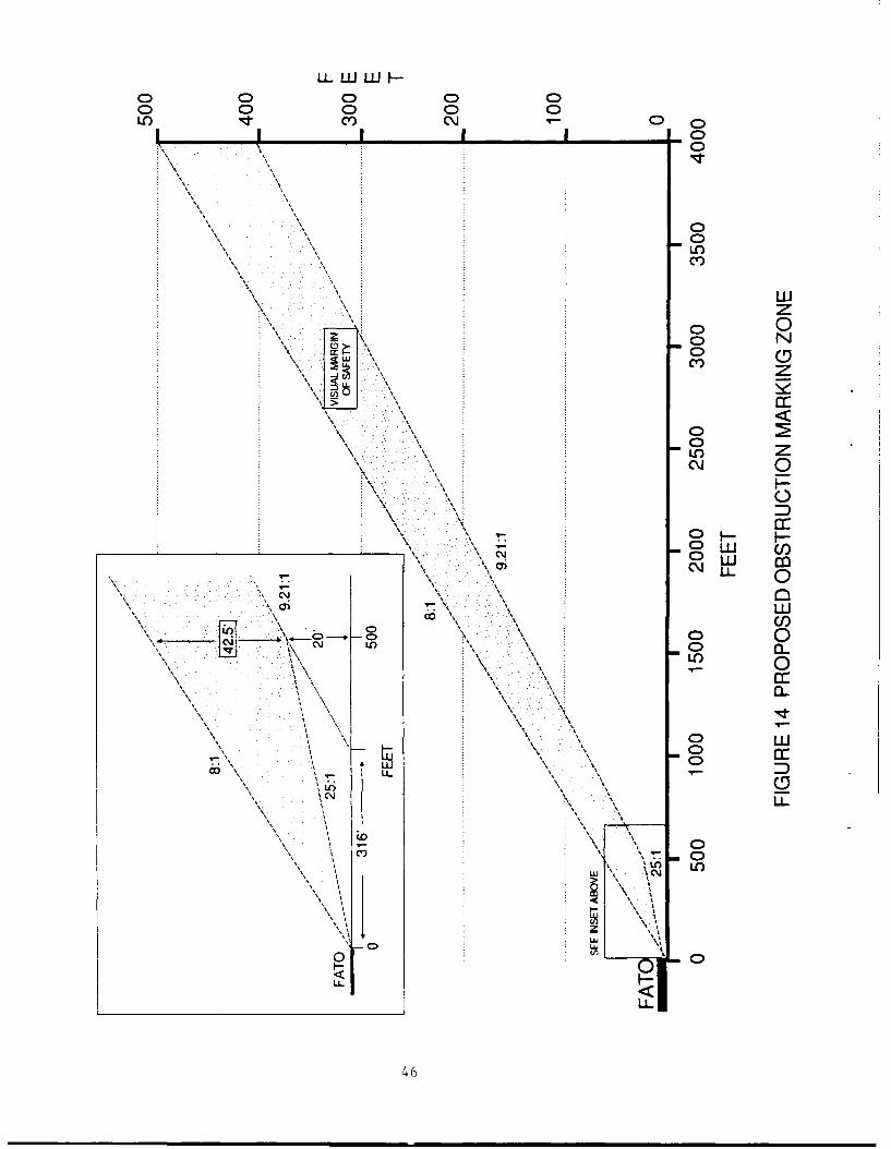
LLLI WUJ I-
o 0 C0 001.O e) C'~J C0 C
C) 0
SC) N
LO
ow c)
00 N
C) C) 0ci C)~
5 .5 .- LO
I LLS I L
7:*
0
N46
additional land under the approach/departure corridor(s) hasseveral benefits. This land:
o provides additional ground/air space to supportacceleration through translational lift, thereby increasingthe payload and operational capability of the helicopter,
o increases the capability of the helicopter to operateproductively at higher density altitudes,
o provides a safe landing area in the unlikely event of amalfunction requiring a forced landing immediately after
takeoff, and
0 provides a safe landing area in the unlikely event of amalfunction requiring an immediate landing during approach.
4. Install additional wind indicators where needed. - Thisrecommendation is directed at those locations where operationsoccur near large buildings or obstructions. Typical locationsinclude heliports adjacent to hospitals, heliports with hangarfacilities, and city-center heliports where the wind may beobstructed or channeled by surrounding buildings and therebyalter its velocity and/or direction. Multiple wind socks shouldbe considered when obstructions may affect the accuracy,
applicability, or visibility of a single wind sock.
5. Provide proper heliport surface composition and adequate surfacemaintenance. - Helicopters are sensitive to the composition andcondition of the operating surface. Any protruding obstruction,no matter how small, may cause a mishap. It is also essentialthat the operating surfaces be able to support the helicopterunder all conditions. Landing gear may stick in sand, dirt, mudor even asphalt on hot days. Concrete is preferable toasphalt. It is also essential that operating areas remain freeof debris to prevent rotorwash blown objects from potentiallyinjuring personnel, damaging property, or causing damage to thehelicopter.
6. Remove the "hold open rack" feature on refueling nozzles. The"hold open rack" allows the operator to refuel aircraft withouthaving to manually hold the fuel nozzle open. This featureallows the operator to walk away from the aircraft during therefueling operations. The automatic shutoff feature in therefueling nozzle is a safety feature and should not be reliedupon to stop the refueling. The consequences of a fuel spillare too great and therefore any device that allows automaticrefueling should be removed.
6.2.3 Airport Design Issues
At airports, the largest percentage of helicopter mishaps wereobstruction strikes on the airport (59 percent). Other significant. causefactors included mishaps related to forced landing on takeoff (12percent), and rotorwash (12 percent).
'.1]
Based on these findings, the following recommendations are offeredregarding heliport design at airports:
1. Obstruction Avoidance - There are primarily two types ofhelicopter obstruction strikes occurring on airports -- rotor(main and tail) strikes and landing gear strikes. There are aconsiderable number of objects at most airports that representpotential obstructions to helicopters. Several optionsconcerning parking and refueling areas are presented to reduce
these hazards:
- Use trucks to refuel helicopters to avoid having to
position the helicopter too near the refueling facilities.
- Install long refueling hoses in the refueling areas toavoid having to position the helicopter too near therefueling facilities.
- Recess facility operational equipment, such as groundingrods, tie-downs, etc. Flush mount lights when not
prohibited by operational factors such as snowfall. Uselow impact resistance mountings for lights when flushmounting is impractical.
Another important consideration in helicopter obstructionavoidance at airports is the use and placement of groundmarkings. Usually designed for fixed-wing aircraft, markingsprovide both guidance and obstruction clearance. However, thesesame markings, particularly centerlines, may not provideadequate clearance for rotary-wing aircraft, and, in fact may bemisleading to the helicopter pilot, resulting in a mishap.Three suggestions to help prevent obstruction strikes arepresented here:
- Place specific (distinguishable) taxi lines in refuelingareas for use by helicopters. They must be placed farenough from the fuel pumps and surrounding obstructions toaccommodate the largest expected helicopter. These linesmust be noted, possibly with script, as specifically foruse by helicopters, such as "HELICOPTER USE". Thefixed-wing centerlines may be scripted with"NO HELICOPTERS NO."
- Place specific boundary lines near obstructions to help therotary-wing pilot judge distances to objects. These lines
might be highlighted with script such as "CAUTIONHELICOPTER - DO NOT CROSS".
- Mark obstructions, especially poles, with strips offluorescent paint or tape to highlight them. This isespecially helpful at night or on overcast days.
48
2. Operating surfaces must be flat, free of debris, and wellmaintained. - Loose objects and debris in and arcund helicopteroperating areas on airports have been responsible for a numberof mishaps. Because of rotorwash, helicopters and helicopteroperations are extremely sensitive to debris. Objects such astarps, plastic bags, rocks, dirt, and snow represer.t operationaland safety bazards to helicopters. Dirt and snow areresponsible for brownouts and whiteouts, 'espectively. Rocksand other debris blown around by rotorwash have caused physicaldamage to nearby structures, aircraft, and personnel, whiletarps and plastic bags picked up by rotorwash have damaged mainand tail rotors. Dependii;g upon the nature of the mishap,damage can lead to a catostrophic mishap involving total loss ofthe aircraft.
Besides being free of debris, operating surfaces must be flat.Objects placed in helicopter operating areas should be recessedwhenever possible. HelicopLers aw airports have caught skids ongrounding eyes and tie-downs.
Helicopters have considerable flexibility and may operate from manylocations on an airport. However, most airports have one or moredesignated takeoff/landing area(s), usually located on a parallel taxiwayadjacent to an operable runway. At times air traffic controllersaccommodate operations tL,/from areas other than the designated takeoffand landing areas. This accommoiation is made for a variety of reasons,to include time savings, separation from fixed-wing aircraft, increasedoperations, and ease of pilot/controller workload. Design considerationshould therefore be given to operating areas other than the designatedtakeoff and landing area on the airport or runway. For instance, if takeoffs and landings routinely occur near fixzd-base operator's facilities(FBO), then FATO design standards should be applied to that location.
The following specific items are included for those airports whereoperations do occur at other than the designated helipad location orrunway. These items are included as guidance to assure that helicopteroperations will be afforded an adequate margin of safety at all times.
3. Mark wires in the approach/departure corridor. - If helicopterstake off or land at other than a lesignated helipad location orrunway (e.g. near airport boundaries), marking wires under theapproach/departure corridor may be appropriate. The suggestedguidelines for marking wires are the same as discussed for thosenear heliports in section 6.2.2.
4. Install additional vind indicators. - When helicoptersroutinely take off or !.nd at othec than a designated area orrunway, additional wind indicators may be warranted. This isespecially true when these operations occur near buildings,hangars, or other large obstructions.
5. Remove the "hold open rack" feature on refueling rozzles.Removal of this feature will help to ensure that the aircraftwill be attended during refueling see section 6.2.2).
49
6.3 CIVILIAN MISHAP DATA
In performing the analysis for this study, several items specific tothe civil mishap database and Information &,ailability were noted.Recommendations to enhance the data, from a rotorcraft mishap analysisperspective, are presented below.
6.3.1 Update NTSB Mishap Form
The NTSB investigator's report form has undergone several changesover the years. The current form includes supplements which containpertinent mishap information. However, these supplements are nt alwaysused by the investigators. Therefore, it is suggested that the term"heliport" be included in the accident location field on the primaryfactual report form. In addition, this field should also incoL-porate theerm "vertiport" i i anticipation of certification and integration of
tiltrotor ai-craft into the National Airspace System (NAS) It would bcof great b2nefit in safety analysis and studies to insure thatsupplemental forms be used by investigators whenever possibie. Theinformation that can be gleaned from mishap reports is extremely valuablcefor safety purposes. Supplemental forms provice valuable information forsafety studies.
6.3.2 Need for Additional NTSB Resources
The NTSB performs an extremely valuable service. It is alsorecognized thaL the NTSB must perform this service within budgetaryconstraints and that the same level of attention may not be given to eachmishap. Therefore, it is important that the NTSB be provided withadequate funding to support their efforts. Mishap analysis and theresulting safety recommendations are cost beneficial to the community aswell as to the aircraft indistry. The fact that mishap analysis may leadto a reduction in the number of fatalities and/or injuries makes itextremely important that NTSB be provided additional resources forefforts to understand mishap causes. Currently, the Hetail avaiiabl, oni >torcraft mishaps is often skimpy. Without additional NTSB funding,this situation is no" likely to improve.
6.3.3 Include Civil Incidents in Database
A significant distinction exists between the civilian and militarymishap databases. While the military archives both accidents andincidents, the civil database contains primarily only accid-ritinformation and very few incidents. The type of information obtainedfrom incident reports used in this study emphasized the need forarchiving incidents as well as accidents. While mishaps such asrotorwash incidents and minor obstruction strikes may not be costly interms of lives or property damage, they do highlight possible designinadequacies and their overall importance to safety studies. Therefore,these occurrences are significant in thE: design and operationalinformation they provide. A means of reccrding and archiving thisinformation could be a significant aid in heliport dsign and operationalguidance.
50O

6.3.4 Public Service Mishaps
As of September 1988, Federal Regulation (49 CFR Part 830) requires
operators of aircraft involved in "public use" mishaps to report thesemishaps to the NTSB. This information is reported on Form 6120.1, t.Le
operator's reporting form. Even though this information is reported,NTSB is not authorized to investigate these mishaps unless requested by
the agency involved in the mishap. Funding is limited for these purposes.
6.4 TAIL ROTOR PAINT SCHEMES
One manufacturer has indicated that tail rotor paint schemes can havean effect on the number of accidents involving tail rotor personnel
strikes. Thi manufacturer stated that they had experienced a
significant drop in the number of such accidents when they adopted a morevisible paint scheme. The FAA should study tail rotor paint schemes todetermine which is most visible while the tail rotors are turning.
6.5 FUTURE CONSIDERATIONS
This effort was designed to understand the manner in which heliportdesign may contribute to helicopter mishaps. From a review of thecivilian and military mishap databases, it is apparent that landing sitedesign does factor into a significant percentage of mishaps which occuron or near heliports and airports. Although not the major contributor tothe overall number of helicopter mishaps, facility design related mishaps
do result in financial and operational burdens to helicopter and facilityowners, users, and operators. Therefore, instituting changes to reducethe number of facility design-related mishaps seems appropriate in light
of the results of this study. Several suggestions have been included inthe hopes of reducing design-related mishaps. The suggestions presentedfor recording mishap information would aid mishap studies and help to
confirm the adequacy of design guidelines and standards presented in the
Heliport Design Advisory Circular.
It would be beneficial to repeat this, or a similar effort, in aboutten years to analyze the effectiveness of the recommendations herein inalleviating heliport mishaps. In addition, further research and
development studies designed to investigate operational issues and toestablish specific guidelines as to the minimum size of various operatingareas and required obstruction clearances are needed. Such efforts
provide valuable information concerning obstruction clearance and areextremely useful from a design viewpoint.
REFERENCES
1. Heliport Design Advisory Circular, (AC 150/5390-2), Federal Aviation
Administration, Washington, D.C., January 1988.
2. Heliport Surface Manuevering Test Results, DOT/FAA/CT-TN88/30,Federal Aviation Administration, Washington, D.C., June 1989.
3. Heliport VFR Airspace Based on Helicopter Performance,DOT/FAA/RD-90/4, Federal Aviation Administration, Washington, D.C.,
November 1990.
4. Helicopter Physical and Performance Data, DOT/FAA/RD-90/3, FederalAviation Administration, Washington, D.C., November 1990.
5. Helicopter Rejected Takeoff Airspace Requirements, DOT/FAA/RD-90/7,Federal Aviation Administration, Washington, D.C., November 1990.
6. Evaluating Wind Flow Around Buildings on Heliport Placement,
DOT/FAA/PM-84/25, Federal Aviation Administration, Washington, D.C.,October 1984.
7. Rotorcraft Acceleration and Climb Performance Model, DOT/FAA/RD-90/6,Federal Aviation Administration, Washington, D.C., May 1990.
8. Offshore Heliport Design Guide, Louisiana Department ofTransportation and Development, New Orleans, Louisiana, May 1984.
9. Code of Federal Regulations, Title 14 Aeronautics and Space, Parts400 to 999, Office of tne Federal Register, National Archives andRecords Administration, October 1989.
10. Minimum Required Heliport Airspace Under Visual Flight Rules,DOT/FAA/DS-88/12, DOT/FAA/AS-89/I, Federal Aviation Administration,
Washington, D.C., October 1988.
11. Brooker, P. and lngham, T., Target Levels of Safety for ControlledAirspace, Civil Aviation Authority (CAA) Paper 77002, London,
February 1977.
12. Heliport Visual Approach and Departure Airspace Tests, Volume I
Summary, DOT/FAA/CT-TN87/40,1, Federal Aviation Administration,Atlantic City, N.J., August 1988.
13. Heliport Visual Approach and Departure Airspace Tests, Volume IIAppendices, DOT/FAA/CT-TN87/40,11, Federal Aviation Administration,
Atlantic City, N.J., January 1988.
53
LIST OF ACRONYMS
A/C AircraftAC Advisory CircularAGL Above Ground Level
CFR Code of Federal Regulations
DOT Department of Transportation
FAA Federal Aviation Administration
FATO Final Approach and Takeoff Area
FBO Fixed Base OperatorFOIA Freedom of Information Act
M/R Main RotorNAS National Airspace System
NOE Nap-of-the-EarthNTSB National Transportation Safety Board
SOP Standard Operating ProceduresT/R Tail RotorVFR Visual Flight Rules
WSPS Wire Strike Protection System

APPENDIX ASUPPLEMENT G - ROTORCRAFT
National Transportation Safety Board NTSB Accident/ Incident Number
FACTUAL REPORTAVIATION
1 Main Rotor Blade Type 2 Tail Rotor Blade Type 3 Auxiliary Fuel Tanks
O Elwooc El vsn)r'C El Non,-
El []tAeia El 0ie El pr)3 Dl Comoosoe j Ec " ~El E~tprn;!A Qine' u!'r re
4 IFR Certitication 5 Stability Augmentation System
i E l 0~ N r. E l
6 Engine Out Warning 7 Low Rotor Speed Warning 8 External Load Operations 'Mu/tie entry,
Il Not 'nstaiiec A otrp' E) N- 0~d~ Y A E
2 ) C'O E : El N FA',
4 ElOn 29?! UflKnow< 1, El kr: vU
9 Type External Load Operation 10 Long Line 11 Length at Long Line
ElConstruction. A Ele~i Fee*___SlAenia! Apolical,c- B 07'..E v'n: i
El Loggnq
3 Elmeae~acEl Aeria, urP
12 Load Cell/Computer Utilized 13 Weight ot External Load 14 Load Jettisoned t Muzofe entry) 15 Lancing Area (Multioje entry
El e, E Estrnate: ' E £e,r.- *cacE (El ~ E \er'e7i - Enac,' l
A lyrne' -AE
16 Obstructions 17 Component Separation in Flight MLu;!'n'e en :ry 18 Component Separation Postimoact, Mulioe enr'
El Tre El No1 El),.[ N,,,2E Wires [ilie, El ,enr'jl (]"s: 'j' 01-E ~'~adrer
2El Buroncas cons!,'jcno' Ela'bnn c nr*' El a'rno 'rni
C-E EEo,,rmrent vencr-es SiaEl iza -f" El5El lerrai El M.1n rTorin iaop - El- d'(0o tflOt
ASoec' Et '; rC_)1-.' t'6r setE Ma -"or rot; assePr-':
0~ -,a,!E T r~tor biaie, - 7l'1'1'' Fdae
El ',a, in'r~ ii nt asenTI- El Ta- r sir ri , assenti
El Mai rarnsm,5s,'-E Mai rrsji
1 Elintermediate oea' o nj El irteelalf cie' r
El a. roor qea' u,,, El 7a, or a artm,
El verltil $ r' r'v -- El ve n pvi
13 ElSkids Floatfs 3~ C3 Skuds Fioatcs14 lDoonisi 1. El Door~s
A Otmer A Otner
NTSB Form 6120.4 Supplement G 1-8' aqe 1
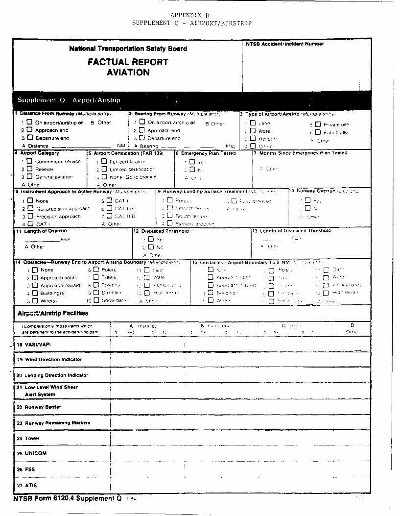
APPENDIX BSUPPLEMENT (~-AIRPORT/AIRSTRIP
National Transportation Safety Board T AcetindntNm r
FACTUAL REPORTAVIATION
1 Dletance From Runway (Multipie entry) 2 searing From Runway MInrrp.e e"'. 3 Type of Airport/Airstrip (Mitioie entry,
1 03 On airport/airstrip or B other 1 0On airport, airsirico or 8 Orne, LaC P vate use2 0Approach end 2 0Aoroacn eno wae PDi s3 0Departure end 3 0Departure enc HetiveA -n
A Distance ___________ NM A Bearno a_________ ,.~ 400'n
4 Airport Category 5 Airport Certificatton (FAR M39 6 Emergency Plan Tested 7 Months Since Emergency Plan Tested
1 0 Commerciai service ,0C Ful certrt,catio, 0 ye-2 0 Reliever 2 [C Limireo certificatior I C3 0 Ge'e-rai aviation None, Go to block
A Othe, Otne-8 Instrument Approach to Active Runway 61,itroie en,(. 9 Runway/ Landing Surtace T reatment ~ ' 110 Faunway Overrun 'bt_-
1 None 5 COAT 1 Cpwo~,L 0.O_\e
2 '-.p~recision aporoact, [3C CAT HJA C Sno:~t,~'- An
3 0 Precision approact, 7E COAT l11P 2 Forjar lete~ r
4 03 CAT IA Otne' 4 ar.ofovf*'
11 Length of Overru~n 12 Displaced Threshold 13 Length of Displaced Tnreshold
________Feet 1 Y e:r4,
A Other 2 CNo c urn-
A Otne-
14 Obstacles-Runway End to Airport/lAirstrip Boundary i Muitfure er'.f 15 -Obstacles-Airport Boundary To 2 NM e''C
10 None 60D Polets 11 C ttc 1 Non' -'oieD ;
2 Approach lgts :0 reeis 7 Cvt 2~ V4r a. e
30 Approachnavaid5 lower- .e'tK._, (Ie. "tcaO
4 Builcingls 9 Drr'a- t..C H. 'a C B, l r r arnerra,
5 [3WirelsI 10 0 SnowvDnar' A Otn.o r",o
Alt-. AirstriP FLcilities
(Cornoiete onily those items whrcn, A rrrltrirec 8r' : C .D
are Dertinent to n@acciafriiciont 1 ye 2 r, Y, 2 % 2 Otne
1a VASI/VAPI
19 Wind Direction Indicator
20 Landing Direction Indicator
21 Low Level Wind ShearAlert System
22 Runway Barrier
23 Runway Remaining Markers
24 Tower
25 UNICOM
26 FSS
27 ATIS
NTSB Formh 6120.4 Supplement 0 1-4
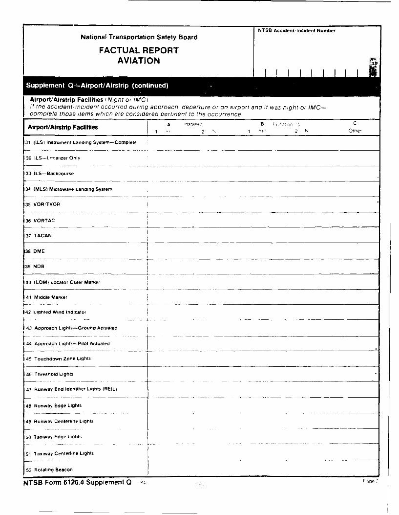
NTSB Accidentv incident Number
National Transportation Safety Board
FACTUAL REPORTAVIATION
Suppemen 0 * Aipr/isr cniud
Airport/Airstrip Facilities (Nigh~t or IMCiIf tme accidentl incident occurred during aporoacti. departure or on airport and it was night or IMC-corn pete those items which are considered oertinent to the occurrence.
irotArti Facilities A nsa'-B ~~C'n12 1FY- 2 N Orne,
[31 (ILS) Instrument Landing System-Complete
32 I -atizer Only
33 ILS-Backcourse
34 (MLS) Microwave Landing System
35 VOR7TVOR
36 VORTAC37 TAA38 DME
39 NDB
40 (LOM) Locator Outer Marker
41 Middte Marker
142 Lighted Wind Indicator
43 Approach Lights-Ground Actuated
[4 Approach Lights-Pilot Actuated
45 Touchdown Zone Lights
46 Threshold Lights
47 Runway End Identitier Lights (REIL)
48 Runway Edge Lights
49 Runway Centerline Lights
50 Taxiway Edge Lights
51 Taxiway Centerline Lights
52 Rotating Beacon
NTSB Form 6120.4 Supplement 0

NTSB Accident, Incident Number
National Transportation Safety Board
FACTUAL REPORTAVIATION z
ffP.@ pp(a tiunway used, 56 Type VASI iiunway used 57 Type Runway Edge Lights 58 Runway Lights-intensity/SettingS0 ALSF-1 6 0 MALSR 02-ra, A ote i -unwav -7 rTes
2 0ALSF-2 7 [DLDIN 2 3-t~' On3 0 SSALF 80E RAIL 0 T,-coz -
4 SSALR 9 F- ODALS 0 T-VAS- 0 P_5 0MALSF A Ctne, t z LA Eltr
59 Point Wher* Aircraft Left Runway/Landing Surface (Mwrcoie entry 60 Departed Runway, Distance from Trifelhold1 0 Aooroacn end 0 R1" slce
2 0 D ca-ture endi El 0Nor),- e.__
3 0 Left slde A 0"Tre
61 Type of Ground Contact on Runway Landing Surtace 62 Point of Ground Contact 163 Ground Contact. Distance trom 'Threshold1 0l Toucndaowr 0 AnoDroacr erA:
2 0 imoac: Deoan..ur erc FP
A Otner
64 Ground Contact. Bearing from Threshold 65 Point Where Aircraft Came to Rest. Distance From Runway Threshold____________Deorees maonet,- 0 A~ra~enc
A Othe, en " e- On-
66 Point Where Aircraft Came to Rest, '67 Runway Profile 68 Average Siope Up 69 Average Siope DownRelative Bearing frorn Runway I 0Leve El 0 Perer r-'uHeading 0 u 01 ~co. C"c- Percer" Q'ade
A Otne,
Tnis section to be comolecid ror alt accicients inciclents OCCL~rrin.Q ouriric ta~eoff aporoacn or ta'nc ar a imttec or fi t
certification airport.
70 Runway RCR Recorded j71 Runway Friction Measuring Equipment 172 Type of Runway Friction Measuring EquipmentON c, Aaianje-[se-E ; 0 s 'j-
Yes-read'inct D0A iasnae no:Uct s -' c srP
E Ofne, 13 %): ajaiian- 0e -*~ E]
A Otu. 0M~ O '.'ev,
73 braking Action Report 74 Pilot Aware of Braking Action NOTAMI0[ No re;)or Pon 0 El:~0 ooc ONEJ F a,, A OT A
NTSB Formn 6120.4 Supplement Q 0,c
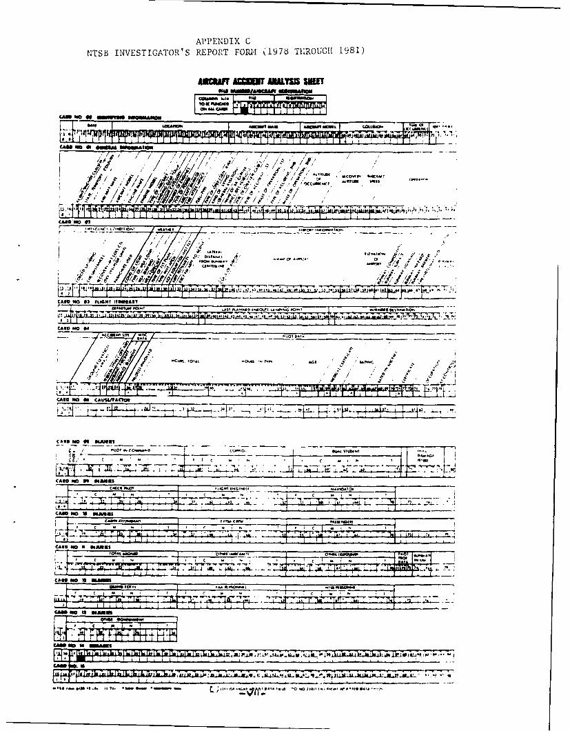
APPENDIX C
NTSB INVESTIGATOR'S REPORT FOIU41 (1976 THROUGH 1981)
AuCUafr ACinir MALM SWI
IQa ra.* * om,
CARS NO* 00OSImM we"omIM
41 4fi# " '
'4.'4E,~~~~~"CWI c.404.. t. .*'444!'
'44 s* ,. m m Wl
CARD NO *0 UGN ISii
4-7 -. V -.77
to, -or
CARD no if MAUWAOO
CARD NO if 4NMIS
CA"S NO if HAMIS
CASD ISO a smi
cam no IS,

CAM NO WCSAM BATA
aw~~~a,, 1". ftfl UTO
CAM NO V
W Ah4~A a'.cwat
I / ILI
CAWS NO 20
1,,dj~//--I" No It'
CAB. NO W.
CAM NO U)
WWIISA4W Dd~ fma~ m~a. C*1 OcKM
MT?" =m
"A oICO Cm
IP(ma DTA
Al , 4ppI
CAM/ No 29 //m-~w10/ / ~ / Ii%
U gno~-aJ~vAA /(L/it,
-v.~~~ ~ ~ ~ Iml w P NGN Dt61 as6 o o % IK A"

APPENDIX DNTSB INVESTIGATOR'S REPORT FORM (1982)
NTS3 ACCIDVIT/INCT IPOtT
6120.D
DATE-OF ACCIDENT STATE OF OCCURREC AIRCRAFT REGISTRATION "N" NUMBER
aASSIFIC&TION NTSB ACCIDENT/INCIDENT NUMIER
Z MAcident
E Incident
NTSB Form 6120.4D (1/82)
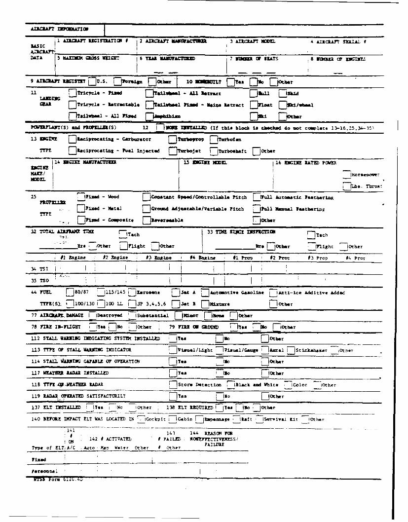
RA1I AMCAFT 3ZGSTAI 9 2 AZlCRAFY KuAC=n 3 AIC."~ PKWM k Aic.Ayr SULbi 9
DATA~ GRS WE= 1sucr 6 YZAR uHAC!U 7 you= OF SLATS OF UZBX c INL.S
9 A.IILAST lIVW~ [3 S. Ehwto.g, [Dot:; 1 WK IL es 0% 00hr
11 AN= 7Ti~z~cxe - Flia ElTallftes.1 - ALI &street [3h&±1 [3a±dA
GER 7 ri71 - &-"-atable allbel ii.d - NaIn. u=.at Efri~t Eis±,/uboi
13 ZNV( j1savcatlas - Carbumtor F Twtrp Efrwtian
TYPE O~eioc~ating - Fuel injected jiuziacie-t [3murohat E3Otbar
14 =G= XMA TUE 1.5 ENINE XM j 16 IURATE) PWEuGIEz
MAKE/ HorsevawerHMEL
741b a. TrstZ.5 7172d- Wood [3Contant Speed/Controllable Pitchi Evun u tomatic beathering
TYE FLza" - Hata.1 71 Giound Mdjustable/VarlAble Pitch 71wuli Hanual featheringTYPE 3d - C6"alte Ej1awemeble ElOtber
32 TOTAL AIRPRIMN TIME[3ec 33 TIM SlpCE El Tach
________ Brs [3Orber E]Fighsb flOthar _________e E]otber ___PLght liotber
#2 EngIne 02 ftgine J3 Engine i 0 Inxine, #1 Pmo 1 2 Prem #3 Prop #4 Pror
FM 808 M _ 1/145 [Kerosene [Jset A []Atowtiv. Gasoline EI~ti-ice Additive Added
77 A.l- ,DAMAGE F-Destroled - Sbstantlal Ej~±nar D]aum Lloter
7s2 r sLL-Y& LN 10 79 nnh an UE ct IITe. Dis, LOther
1.13 TYPE OF STALL NIXJ1 IICATO D3isa.1/Uight ~v~aa 'a 7A.rl [JSric.Jtahaker -IOt her
114 STALL guANIUC CAPABLE or oFRA~io [3 lam Igo EJOLIer
1.17 WE.TU RADAR INSTALLED D es5 IN.o Ei0tker
USB TMP .40*MEATE RADAR Ii[Store Detect iot F7I1ack and White 77Color O1ther
1.19 RADAR.OPIRATED SATISFACTOR.ILY 1 [Yes - I. 0 tu
137 FLY INSTALLED tje IP~ Other 138 ELT R37UIRZf LJTes --JR.3ohe
140 UEFOftZ IMPACT ELT WAS LOCATED IN 7 Cockplt __ Cabin].,em~ __ lft I~rvLKit tOther
14, 4 4 EASF (f. 13 11 WP O
ON 142 1 ACTTVA~n I AiLzD N(3Etm-ZTrvENEs,Type of ELTtA/C Auto! Man Wsat r r other UOther FILR
fixed
NTS3 Yorm blU.4D
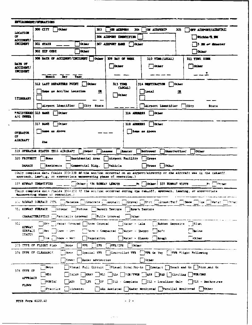
or X* AUM 3=ERE= 45 Ji ri
DT 301Tn - -?Atb 307 A= 3*1 Dfl3 M P Mt9
302 Un~ ofA= r=1"[ohr39M W U 310 TVA(WCAL) 3U DCzn
3.12 ZAST OVAmR 10WI 5EOta 313 TUE 314 Mn=IAn [30her
s as~cnn Loctis.(lOAL)
____ ___ as5eIc10ai other ElLca-1
_______ DAirport Idetfier O]Cit-y Staten - urporTTIdetif ar D cir, state
'M1SM 315 MW 15 Qoeher 316 AmMS EMOteA/ C ON
317 3*1 EDotba - -M S ]to
ORTK lSe as Above - - - 1E9m "n Abe.
AIRRAFT b
319 0P.2ES?.TA WILS A:XLL.rJ( wmr E:Lasa.. Zjaatre air Dre~ E)Umw'±s.&i [3otb*r
320 F10711TT E Dome 7Ela~dnavt Ara mAirport Vacuilty E-1cropsDA)IAGZE []ialAomce 7'Comerta Bldg. [J'ehinla ElTre. Eotbar
(Oul~y coupata do". fields 333-335 Siirbe sco/±nc occurrod on an airport /alrv trip or thba aircraft was in rhoetakeoff,approacb. La",g or eaiproprI.At manewering pba of opeation.)
333 ZDUWAY IDUMTIFTE Zor0ber 134 tfl&T Mun ______Pt 335 U11AT VIZTV _ r,_____Pt
~t~ycomite 4ia~ 1i~4e 3.G-3-2 if the *cc/ize mcxwred dur~ing th rak-..,f, oprCach. Landig, atr sttvriteeaneuvering ph&". U- ovaratiotm.)
s. IATSEUIAC? 2=t. - M&ACAMs lCowrote i *.A prAI t Grzve.) __ir -rsms,/?mf -Sm.w '-ca ?two-s-
15. IMMAX SWJACZ irvun IPoronAI .:S.coorb Tax-,a F]3Dw Twrvore
-B~kACTUI1CS artI!Ali' Groovead 1?ui11 7; r oo',.d m
3Z r)Dr- 77 srtr 'a--arnd F17So. Cruat.2 Jit& .... b D6owEirsADNWA' :] -
F~ca 7-JSno wf-t- DJeatro [1sia - cG.aar ]&
S7 5 -TfM OF PL1HT PLA). W.,~ D]V [9171n []E IrnM _______ ____ ____ ___
376 TY" 0 CLA3Y C sane 7-sp.. V.7 Z-jComtroi1d vn __v Oc ToT 'ITTI Ylit roUowing
[7]rElRadar Advisories ____ D_______________________________________
-I Son IVisual Full jzxcuit 7Vis.eI Stra. 'ht-i []Conct : Tour-h and Cc []Stov.&z, Go370 TTV! O0?1
F3vc)iN 71V.AnA [D ) LFR []DF []IxS - Caimpiate EJILS - Localiser 0m1 EDJnS - backro-arve
FPracrice I3~idestev ZIARA Assisted []Rader Mmiitomed Efrallal Unit*TedDo)
Nibs Form 6120.4tl
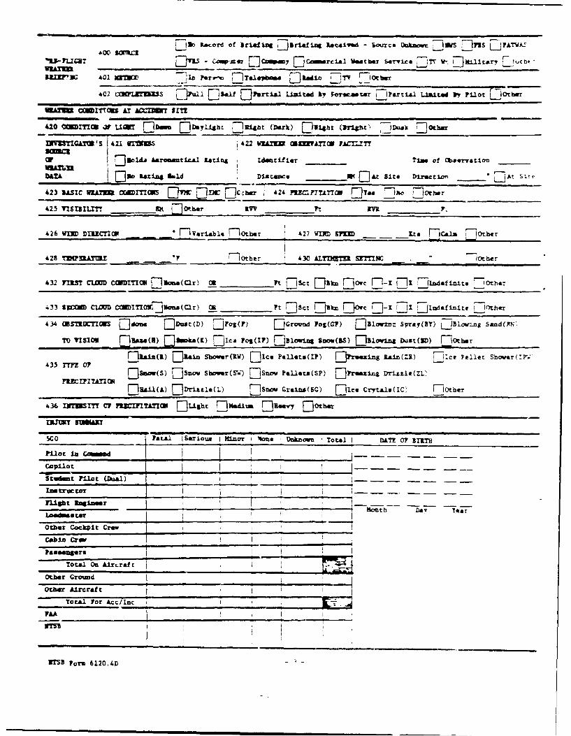
71ftL..rd of brisfing 71irign Received - &ouxce Ukmc 131 [1jn 5 PAWA
"3J- ?LIaT - lr] in, W]Cowrial Wmtbar kmri-cl TT W, 1:]1l~rw1 fcb.-
U.lm'3. 401 mflvZ Pere-mr 7Tapbs [ji~o, 'irT __otm
40-itul j1~l E]12*f jtartiali Limited by, Forecem EL~artial United "v Pilot L1te
420 CWMI03 4? LIW EDww [D~y~. 7214bt (Drk) f:2Ubt~ (ft-iot) -- >m, -0
(7So"Aeramtke. Rating idetifier Ties of Obsetwatior ____
DATAatn.bd DiAtAnce W1 []Atz Site Direction~ * At Slre
4.26 VIX DIRZCTIOm FlVariebie 710tber 1.27 VtXD S?=U Lts []calm EIotber
4.28 !UZUA!~.! 4?r~~br130 ALT)MME SETIWZ 7 0ther
1.32 TIM3 CLOUD COMMON3 flflas(cr) CR _______t sjc t E'zk _7owc 71-1 11 __Indefinit. IF Ithar
433 ZSO1 CLOUD CONI T0I]U..a (Clr) OR F______ t ~Set D tZk [D~ ]13 I .~i.t - -
1.34 OBSTRUCTIN [1]don. 1Dust(D) []Fog(P) FEG. .. d log(CF) D Blov±.: Spray(ay) LJE1-ng Sand(YN,
TOVISO 711 ]msae(H) []I..(Z flc os(17) [1juiouin Sum(BS) El31owing Duut(D) 7,0th.
43 Tn0 3in(R) []i Shower(iW) []Ice Pk1le.(IP) [jfreeaims -In(ZR) '11ce Pellet Sbmov .r'
Fl oSam Lisov Showr(SW) DSnov PeUlat(SP) 7jtreeins Drizzle(ZL2
EUIRA1(A) ED rix"zla(L) snoa Qrains(sc) EIce CrytalseIC thr
1.36 INTUSIY CIP 7!=171I01XI F]L±Ibt E'sdj'- flmery FlOth
500 Fatal 160riOuR I Minor 1 *.e iUkon Total I DATE 0? BIRTH
pilot in Cmmend________ -- - -- -
COPL~lot I--
tudt pilot (Del) I .
Inatur I
________________ I ~ ---- ~ Month Ya ear
Other Cockpit Crew ,
Cain Crew I?aseengers 1,
Total On AiLrLraft --
other Ground___________________-
OthA Ire raft I
Total For Acct[IncI_
FAA ~i
WtEForm 6120.4D-
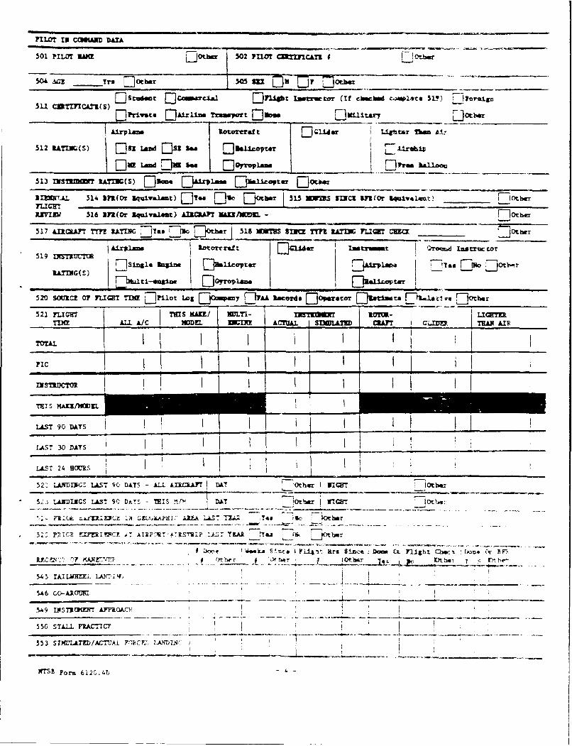
nLor IN CO*Un DAXA
501 PILar SAME Z1Or.hr 502 PUOTr C~tF1CATZI f f-
504 bal Yrs flOther 50 in 71 v T~Iothwr- _______
5u~~~ CKMLI) 1studint EDCMNrCW EnI ~ F ism Lutz.ta (if cbeb cA*1te SUP) ILI Trual.g
tiriat. EDAirliv Ttuapprt EDft.. D7maimar ______ LOtbar
Iafrl.m l~otarraft Ec1u L±.*btaT Um AtI-
512 RAT=NG(S) [ED n~ L- 5 EDUI±pt- r,-
513 INSaT lAYIN(S) Dameui ZJAfrP1.s Duic~@ter ELI____________
DIEWTAJ 514 lfl(Or lquira1at) [IT" L's otw 515 ___MI_______..It Il .
IIVIEW 516 [111.8 U.-vaaw L2CLtF ___________-____________
517 AMCLAFr T" WAING _Jlo. 1io~tbr 518 aUESS TMP IATP 7UIGH CUC= ______
519~~I IN1UT AipmFocrad t or mtroinnt I t;iiItaactr517s=UTO ni Ak-rA. VJmU.cOter Elu hym!.. mO Dtb.r
RATING(S)
520 SM2CZ 0? PLWT TIM Lftiot Log [DOMOM1 DVA [Ifr Rcarim ]Oraratar [1jal.ta [1hIniai" Zive tber
521 FLICT THIS MAW! I MTI- in rmU.IT to=-LITMN ALL A/C "Mm OIE ACUAL. SDLLA UD ~ArCL~m TwA AIR
PIC IIIII _ _ _ I _ _ _
INSTIDCIV ITH:IS KI/NWKL
:::: goAV DAY
LAsT 24 HOUTRS
52- LANDIGS LAST 90 DAS L AUAT BAT 7Other Il tbrn
5;, ,.A.E)ICS LAST 9C -T TI f DA I-O . IN1WflCE rIF(~.1 k AY~ f,- IRE 1.0 LA T Z- yas fc So tber
n- ,' 1-- - -T - - - - 1 -- --.- -
Z )O" e 'ek S.1ixm IFa4i~t art. 8ixce D o CIL t Chw Lkau O'r PRYZ U;2*' 07 KAAr'.TP gOther r* fk I~~J~ tt! T <
545 lkiLbgZL. 1A F:r, -
5A~6 GO-AIGMU7,
5-U9 IINST1IlE17 kaYPRQ l'
5W SILL FACT
553 SZMZLAT&M/ACTUAL YL"I1<CF.W LAJ IfN I
RrS8 Form 6120.4D
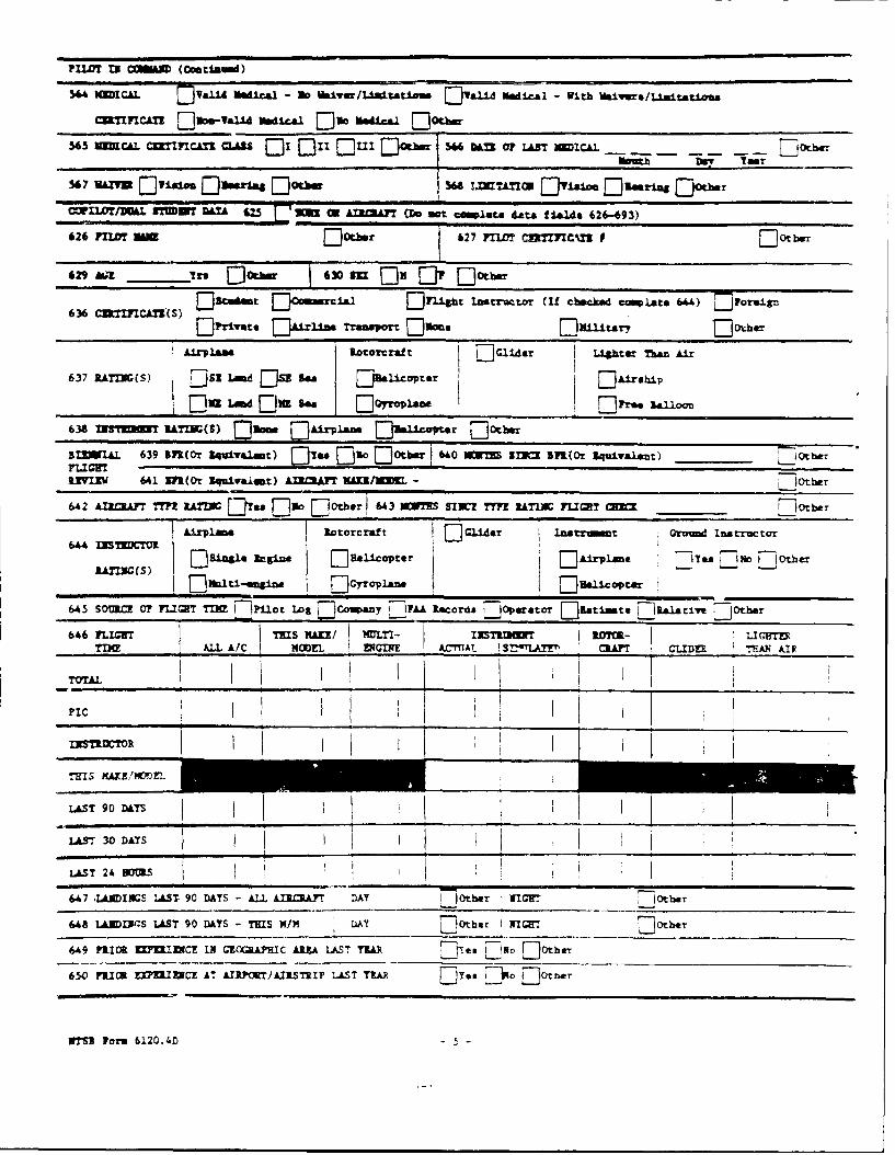
PILOT 13 CMMUM (Cuamda)
544 KDCAL FYaW Medical - No i1ive/Uairtatiou E)YaW M~eial - With Waivers/zLinata~aaa
565 MC6L CIK ICATI CASS [DI []II DuxI EIOtbw 546 Mf 07 LAST NICAL 7 - --
s67 vUYU EJYisiou EDasraa I'lotbe U48 L=UnCWl EJ'alm LDmrig EjOtber
CMILOTUULL nWTID& MA r7=5 c AI1cAyT a~o an coIaa data f 1.1dm 62"-93)
626 PILO MW F~ft.er 627 711.0? C27CX f Ot err
629 Afa _____I's Dfb 63 SU E fr D:otbar
636C:Z~rnATV) szodet []O=mmcial EI~uight Instructor (If chocked compate 644) Eioraign
1Elyriate E31rlin, Transport [Dfame EDuKi tary flotbar
Alrplane Rotowcraf t F-114er I Lihter TIan Air
637 RATIJO(S) 5Led[]uS 5" [R.iptrAiea
638 INFTU 1ATI( 3) [DomE [Airvian []Blconter LiotbeIZIWAL 639 InCor iqulvalant) D a, [. E E]ot 60 2DICZ~ BnUDr 1quiwalait) L1Ot ber
FLIGHTRIVME 641 IF1(Or Iquivalent) AIRCRAFT N IS -' .
642 AI3.CA1T TMP IA~nI Dies Dno [Dfbrl 6U3 MO SIWZ WYP RATING FLIGHT 0= ______~ ot b.,.
Airplane iotorcraft D C"ar lns t Orovm Inarructar
S nING(S) Regine [jalicapter ElA±rV~Ine :]Yes Ffluo Elo0tber
645 SOU= 0? FLIHT T=N 71l±ot Log [jCouany I IFAA Records iOjperator ]nti..mt 7naiariwe [jobe
61.6 TLIMW THIS MAKE/ KLTI- IUSTRIhWT ROTW- ]LIGHTERTMN ALL A/C IEL 1 EGINE ACWnAtL 'IAT!'m CRAFT GLIDER TIIAN Al F
1TTALI I I I _ _ _ _ _ _
~PIC I_ _ i_ _ _ _ _ _ _ _
INS'U'TR I
,HIS MAWN'~E
LAST 90 DAYS I
LAST -VDAYS I
LAST 24U .B=
647 JA IWIS LAST 90 DlAYS - AL Iro~ A lothar TimH _Ot b.r
648 LANDWS LAST 90 DlAYS -THIS KIN MYT [Other I [IHTOtb*T __________
6"9 PRIOR WIU=C 11 GROCRAPIC AIA LAST TZR Dr, E It,,E)th
650 PRIOR KFI CZ AT ArI17WT/AISTRIP LAST TEAP "Yes ipa 7cttsr
WTSU Form 6120.4D
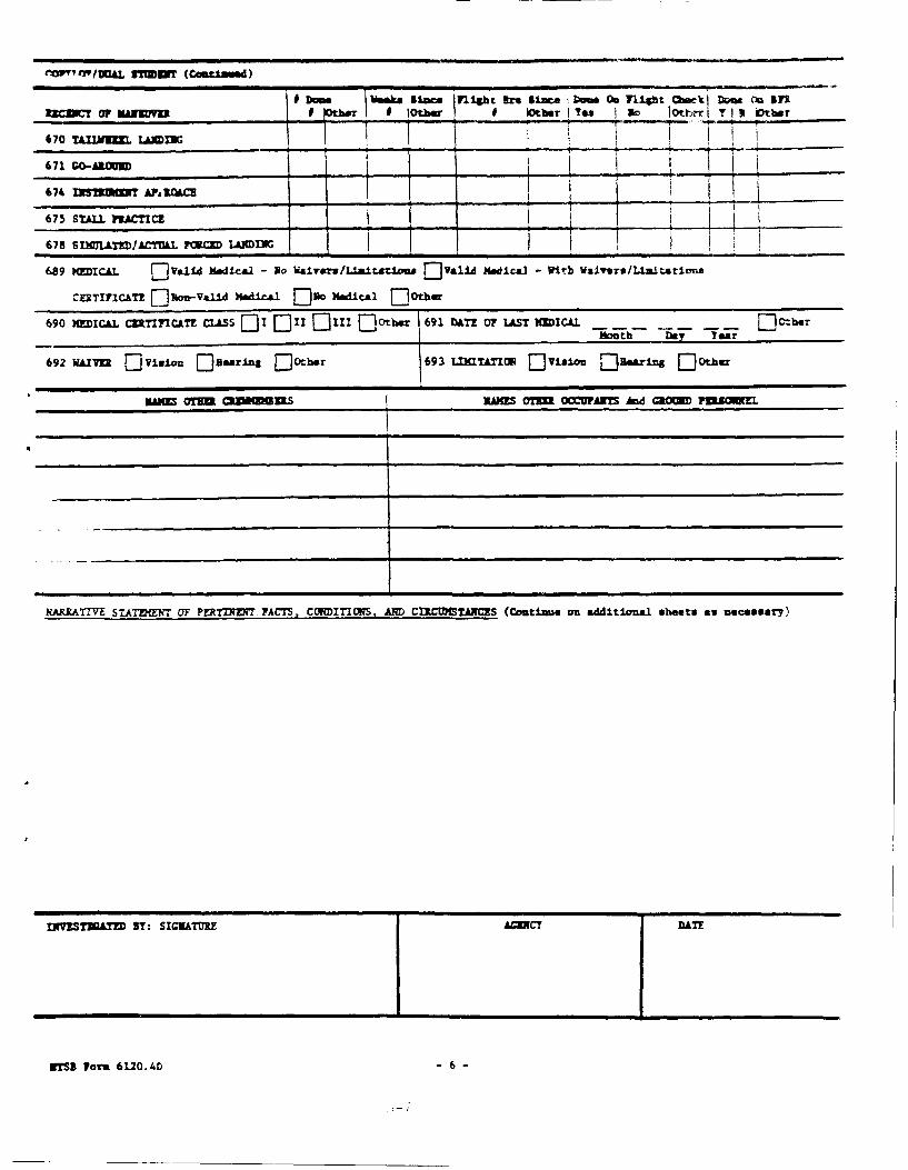
9MrTwYe, AL UT (Coa~med)
Iz~ Dow usaMU SU* _____m___ bw0 Y~htaatlDm nSZ.l..OFMA..fM tbiIT90 otbar * lothar YT No Ioth~r Y 9 iotber
670 TLIXVM. Iflm=
671 GO-AROUND ____I
674 lNS320M A*PNILc
675 STALL FtACTICE
689 MEICAL F Valld Hedica.1 - No Waivrs /1-1-1ttl~o" V NU edical Wlb Walirs/L1 -1tatimts
CERTIFICATE []%-I~V"1 Mbdical EDRO H-dical [other
690 MEDICAL CTIICATE CLALSS []I []II []III E]Otbm 691 DATE 0F LAST KMICAL __----]C-ber
fto;itb -Day Tear
692 WAITER LjVi. Esearins [DOtbor 693 LIXITTflP U Visift Ejumaring [Dother
MAUM 1 CVMZSIiE OTNE OCCinusT An GROUND~ PIRO
KARRATMV STA7MEnT OF PE~rl]ZNT FACTS. CLVIDITI(YAS, AN~D CIRCUMSTANCES (Coutims. an additionalsi het. as necessary)
INYISTWATD BY: SIGNATURE ACY DATE
NTSB Form 6120.4 6D
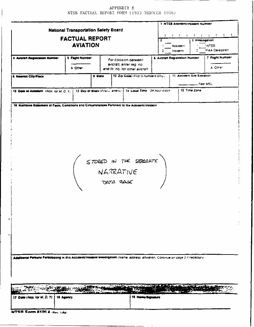
APPEN4DIX ENTSB FACTUAL REPORT FORM (1983 THROUGH 19836)
1 NTSB Accienvsncloent kumboer
National Transportation Safety Board
FACTUAL REPORT 2 3 Investigaion
AVIATION I Accicenz - NTSE
277incicern 2 -FAA Deiegaiec-
4 NwtMo isr boinhufibef 5 Fligh Number Frclionete 6 Aircraft Registration Numb~er 7 Flight Number
aircraft. enter reg. nlo.A Other and ltt no. for orner airc raft A Otmer
I ter" RYPaS State 10 Zip Came t~irst 5 nUMDeSr Orviy, 11 Accicefli Site Eievation
I era I I -ac Feet MSL.
1 12 06ts of A00dent M~os. for M. 0. Yj 13 Osy of Wesi (First . -orters; 14 Local Time '24 flour clocx: 15 Time Zone
16 Natwve Slalement of Facts. Conclitons &no Circumstances Pemlnent to the Acoendncloant
-7~ THE SERMA-7/
*7-
AdafilOfii Persons Parbelbatinq in this ACCIOeltiflidklt tWmsaltion ( Name. aress. allaiiaton. Continue on page 2,? necessary!
S, .. b7 --
WIMC oww Al"f A a.ju
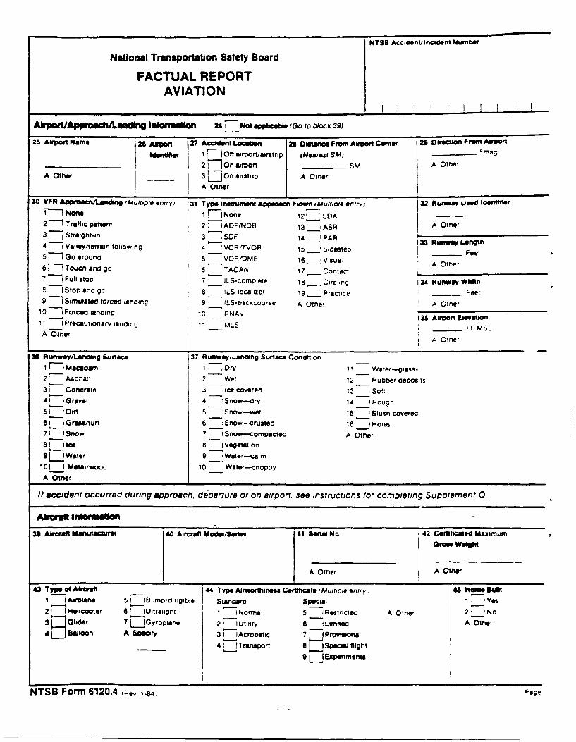
NTSS AciciaenJ Inicleno Numcer
National Transportation Safety Board
FACTUAL REPORTAVIATION
AkpoiVApprochALaning Inforumton 24- o ww& ~IaIGO to blocik 39)
25 Airpout Name 26 Ahrpon 2V Accitnt Locgomo 23 Distance From Airpoet Canter 29 Dore~i From Arport
1 Ideffitfer I1 Off amrporvairstrip (Neares SM) - Maq27 ; On airport ____ SM A Other
A Otherj____ 3 On airstrip A OtherI A Other30 YFR ~OU~Ldf (Mdultiple entrryt 31 Type Inglrumeint Appreech Flown vMulti~io entry) 32 Ruflwmy Used 1dIt"IrIfe
fr None 1 771Nonie 12' LDA2 11 Traffic pattern 2: 7 ADF/NDB 13 ___ ASP A Other
3 Straighr-in 3 SOF 14 _lPAPR3 tiwvLnt4 1Vallay/tenrain following 4 VOPR/TVOP 15,__ Sioestev 13 RummyLengt
5 f oarud5 VOR/OME 16 __ Visua A Otrie,6 77 Touch ana go 6 TACAN 17 _ Contact ______________
7 -7l Full stolo 7 ILS-complete 168_ Circiinc 34 Run'way Width8 Stop ano go 8 ILS-locaitzer 19 __Practice ____Fee.
9 1 Simulatea torceo landing 9 ILS-oacitcourse A Other te10 -iForcea lancing IC PNAV 35 ArOte al
11 -1 Precautionary landing 13 Airport MS..
A OtherA Otrie,
36 RunwayilLanaing Suface 37 RunwayiLantang Sunace Conamton
1 7 a:ac:am I -Dry I' I Watmlas
3 I Concrete 3 ice coverea 13 Sot,Al1 I Gravel 4 Snow-dCry 14 1_ Poug-
5 _I Dirn 5 Snow-wet 15 1_ Slush coverec6Iprawturl 6' Snow--crustec: 16 1 Ho"
71 1no 7 -iSnow-compactec A Other
8 E] ice 8 :lVegetatilongi Water 9 ',Water--carn
10 1 Met11108awood 10, 1 Water-chnoppyA Other
It siccident occurred during approach,. deParlure or on airport, see instructions for compltteing Supoiemnent Q.
AkwMf Inornn39 Akwafl Manuaullir 40 Aircraft MadeiiSoe 41 Serial No. 42 Cerittcmated Maimurri
A Other A Other
43 Type of Alreirft 44 'type Airworthrneaa Cefttcate iMvitioie entry Nom Bur Sil1 1 Airpiane 5 ___ ImD/dIrigible Stanaaro Special 1. Yes21 1 Moeor 6 ' Ultratignt 1 lNormai 5 -1Resnctec A Othe, 2, 'No31 E Ghder I "jGyropions 2 Wtility 61 1Limited A Other4L Balloon A Specify 3 IlAcrobtic 7 L Provittonsa1
41 __Tranaport a Specal flight
g L Exspenmenuui
NTSB Forrnf 6120.4 (Aev 1-84, page
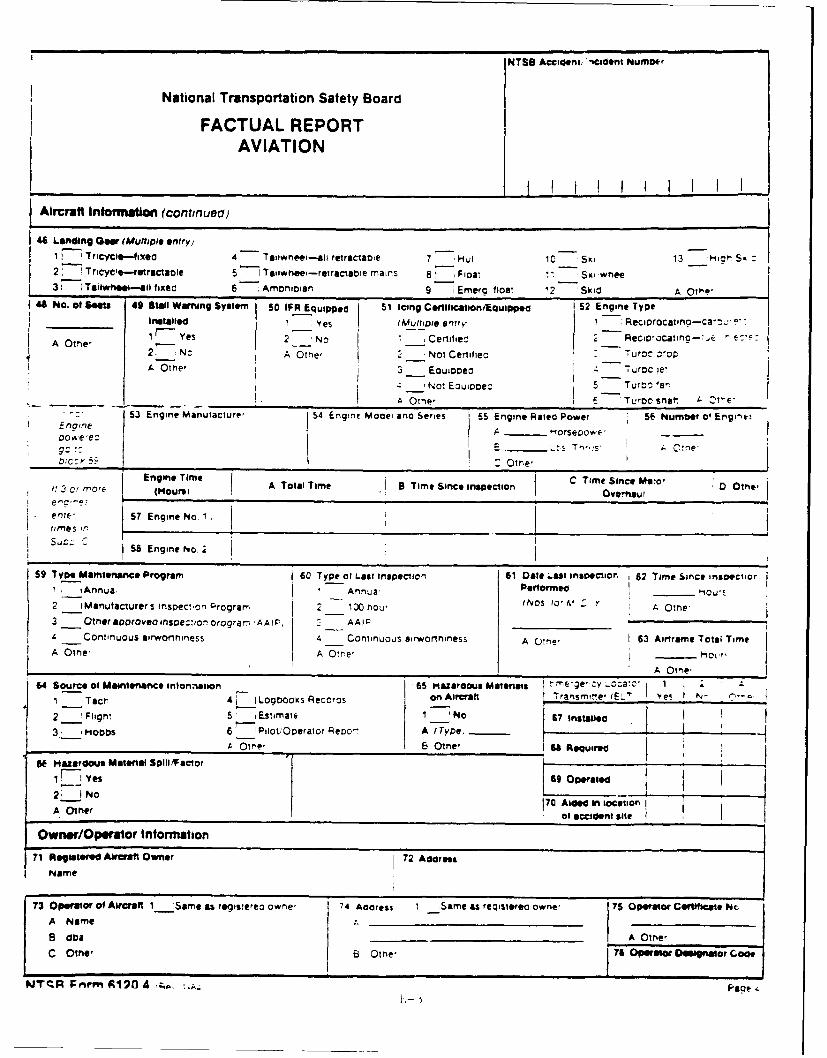
NTSB Acciaenuident Numbier
National Transportation Safety Board
FACTUAL REPORTAVIATION
fAircraft Information (contin uecl)
4Landing Goa (AMultipie entry)177 TriCyCoio-fixeci 4 Tailwreei--all retractaole 7 ,, ~10 Ski 13 Hjor' Sx2 Tricycle.-retractaile 5 1Taiiiiiee-reiractabie mains 8 Fioai 11 Sxi-wtee,
31 Taiiwne.ov-ii fixed 6 Amronioiari 9 Emero lloa* 2 Skid A Q,P1 41 No. of Seow 49 Staff Warning Systemn 50 IFREQuipped S1 Icing Centcation/Equipped 52 Engine Type
installed I Yes I (multile, entry, 1 -,Reciorocatna-car.n :
A~ ~ Ote Yes 2 No __ Certified Re2oa'f~~.A Oltie' 2 Not Centifiec - uoc :oOp
heOt, 3 ___Eoucopec : 7urocie,
~Not Eouooec 5 Turoo 'arA -On e, r Tujrbo sna- . 1e
53 Engine Maniufacture, 54 Engine Mooei ano Series 55 EnieRaise Power 5E humDer at Enginei
-orserdowe -
___ __ __ ___ __Otie
57 Engine No
5Engine Tio 6C Time Since inlOC.il
1! C nnuoe Tta Tme of TimaSnc inspection DI#
59 TypeMaintenaince Prga 60 Typeofainpcon1 Dantre _______pcio,6 Tm Sne nvoto
2_ iManufaciurer S nswect.on Prograr- 2- 130 hou, (Ivos to, &I: A Otne-3 -__Otheer aoroveo ihsoection orogran 'AAIP; _ AAlj_________
A Continuous ifrwortminess 4 Continuous airworthiness A COtne' 63 Aiframe Total TimeA Otne, A OtIle, t9OL"
64 Source of Maintenance Intonation 65 Hazardous maternals mee: .ocac I
1 Tocrv 41 I Log~oks Records on Aicratt Transmine, vEz' Ifes N- r~
25 iEstimate, I 'No 67 tnstansea3_ itoobs 6 Piloti'Operator Reoo'- A t Tyme
ee Hazardous Maerilt Spill/Factor ~O~ te s~qmv
2___ No TO-soinlctoA Othier 7 I aide t scteo
_t0 cdetctOwner/Opeirator Information
71 Re~atoed Aircrati. Owner 72 AddressName
73 Opeator of Aircraft 1_;Same asregisterec owne, 74 Address I -Same as reqosterea owve, 75 Operator Ceirlfir-ate NoA Name __ _ _ _ _ _ _ _
8 at___________________ A Othe,
C Olne' 6 Clitne' j76 Operator Designator C006
WZTqR 1:,,m A120 A , .Pop~
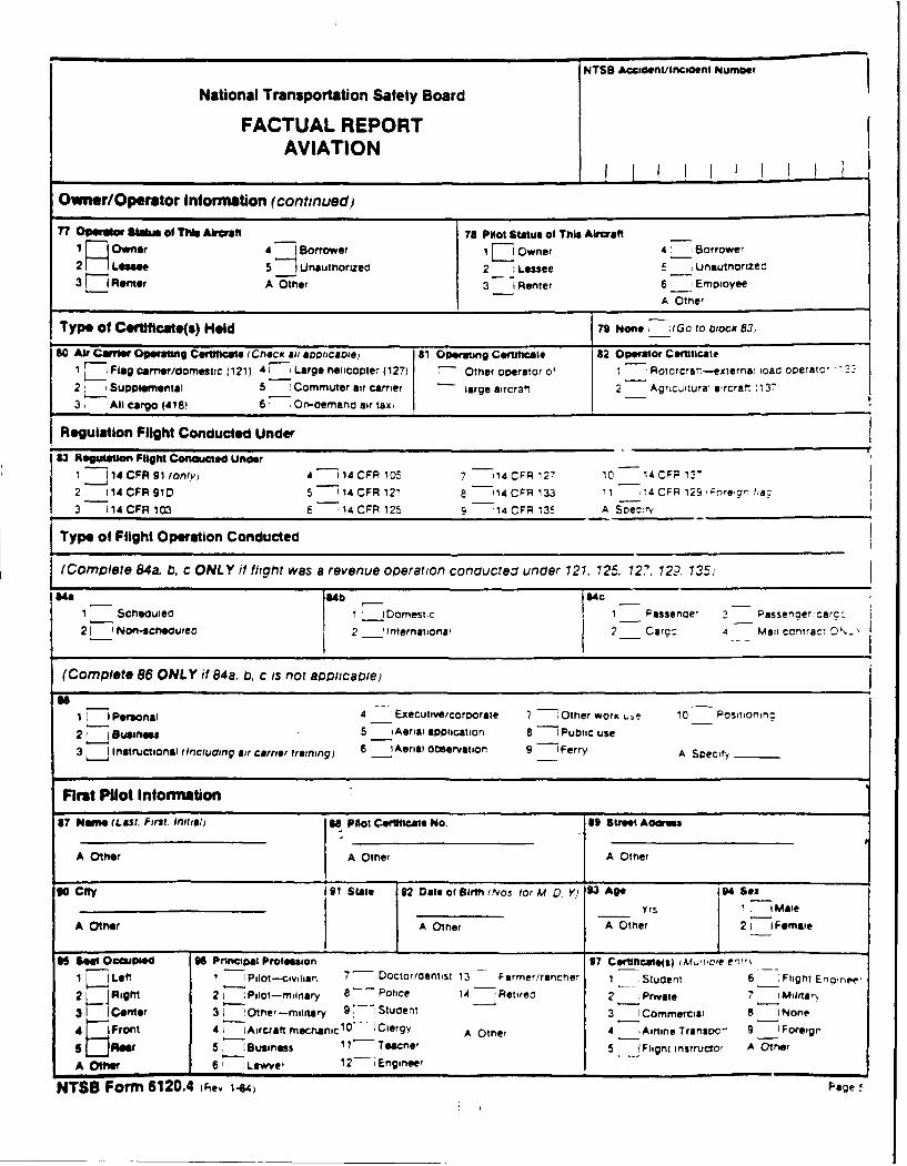
National Transportation Safety Board TBAcdniiietNm t
FACTUAL REPORTAVIATION
Owner/Operator Information (continued)
77 Operato Sftt of This Aircraft 78 Pilot status of This Aircraft14 Borrower I Owner 4. oroe
2 5 Unautnorizeci 2. Lessee E Ufl5utnoL~tze3 Roee A Oer37-1 Renter 6 1_ Emoioyee
A Otne,
Type Of Certificatei(s) Held 79 Nonei; (G .o to otocic 83;
80 Air Cwlr Opeiratng Certificate i Checii aiil appiicaoiel 61 operating Certificate 82 operator Certificate
IZ-' Flag carnerldoomeshtc (121) 4,77 Large helicopter (127) -Other operator o' 1 Rlotorcrerr-externai loacd ooerntc,2 :-ISupplermenial 5 Commuter air carrier large aircraft 2 Agricuiturai aircral (13731 All cargo (418) 6 .On-aemnano air tai
Reguiation Flight conducted under33 Reputamo Flight Conducted under
1i 4 CFR 91 onlyi A - 14 CFR 105 7 14CFR 127 10 14 CCR13'
2 114 CFR 910 5 '114 CFR 12' 8 -114 CFR 133 11 14 CFP 129 orire~cr, he:;
3 114 CFR103 6 14CFR 125S 14 CFP 13!5 A SoDe c: r,
Type of Flight Operation Conducted
I(Complete 84a. b, C ONLY if flig~ht was a revenue operation conoucteC under 121. 125. 727. 72?. 135,i
1 Scheouiec 1 ___ Domestic 1 Passenoe, 2 Passenqercarc:21 1Non-eicneouueo 2 -1_ lrtternationai 2 Carc:- 4 Ma11 CCntra:*. Ov,-
(Complete 86 ONLY if 84a. b, c is not applicable)
1 1,1Pronl4 1Executive/corpo rate 7 Other wor K U-e 10 Posrionirc
21 Business 5 - Aeriai application 8 1Public use3, instructional (Incluaing air carrer training) 6 -IAerial observation 9 1Ferry A Soecit
First PMot Information87 Morrie (Last. First. Initial) SI Plot Ce40MIcat NO. I9 street A 2am
A Other J A Other A Other
90 city 91 Slate 32 Date of Birth NOS tor M 0.Yj 93 Age 94 Seax
A Other A Other A Other 21 ~F @male
IN Seet occupied 9 Principal Profesaiont 97 cortificatels) mu'oD'C en'iT1 IjLeft 1 Pilot--civilan 7 Doctor/coentist 13* Farmer/rancmer I Stucent 6 Flight Erramee-
2 Right 2 :Pulot-miliary 8 Police 14i Retirec 2 Private 7 Milrter
3 Center 3 !Other -mltary 9 stucent 3 Crmrii 8 1Nn
4 Front 4i -IAircraft mechamnic 10 - Clergy A Other 4 iAirline Traripc- 9 -IForeign5 RorB:1usiness I1I1 Teactle' 5 )fFlignt instructor A Other
A ofe 61 Lawyc 12-Engineer
NTSB Form 6120.4 IFier 1-44 page
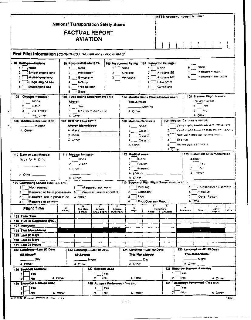
NTSB Acccaeen/incflil Numpef
National Transportation Safety Board
FACTUAL REPORTAVIATION
First Pilot Information (continued) (AMultili entry - olocks 98-102 J98 Astings-Akpisae 99 Rotoncraft/Glidee/LTA 100 instrument Rating 101 Insttuctor Raling(s)
IF None 1 None 1 1None 1: None 6 Glider
2 Single engine land 2 H_ elcopter 2 - Airplane 2 Airplane SE 7 Instrumrent cia"E-
3 r1Muttiengrne land 3 7 Gyrooiane 3- H.elicopter 3 Airplane ME 6 instrument rielicote,
4 "7 Single engine sea 4 Airshiip 4 Helicopter
5 Multiengine sea 5 Free balloon 5 jyoin
-6 Glider
102 Ground instructor 103 Type Rating Endorsement This 104 Months Since Checkt/Endoementl 106 Biennial Flight Review
1 None I Alrmatt This Aircraft fo Oeoulvalert!
2 Basic I Yes Months Yes3 Ao-ance= No (Go to o0cck 105 A Other 2 No4 Ins"-" A A1,. Olm,
106 Monis Since Last BFR 107 OFR ior eoluivaierr) 106 Medical Certificate 109 Miliccai Certiuicate validity
Mon:ns Aircraft Make/Model I1 None Vaic nteclca-no waivers' nrr 'X
A Othe, A Maste 2-__ Ciass 1 Valic meoca-wtr) waivers imitai-c-
8 Moc 3 Class 2 3 77 on vac rneoia tor ths fl:--
C Otne 4 __ Class - A71Excwe:
A other 5 No meoicai ceniticale
110 Date of Last Medical I11 Medicalherimnation 112 Medical wevie'i 113 Statement of Demonatratec
(Nos for M 0.y 1 t (None I None Ability
2 ___ Vision 2 1VislOr' Yes
A Szec'*. 3- 1 etrn N c
A Othier __ A Specify _________ AOn
B Other 8 Other
114 COMISN 06111111111011 MUTiD.i eni, 115 Source ol Pilot Flight Time iMLhuiive er'i'y
1 'Not reouired 5 Requirea not worn 1 _1 Pilot tog 5 investoawor s Este
2 5 Reauirea to be in possession 6 -1Worn at time ot accident 2 iCompany 6 iRewaive
Reouired, not in possession A O5ther 3 7FA Othe, Person47- IAouired to t:e worn 4 -1 PilotlOperator Reon A O tr e',
Flight Time A A/ .8 PA AAAMA/ Moot, s.- Eg.-* cun~ Ad~ua I snw.t I e
125 TotalUt__ _I_ _ (___
126 PliotinCommand (PIC)
127 _nlsc
12 TM li11ae/Model _____J
i2n LAM " Dayls___ ___1 1-___130 LAW30V ON"__ ____ i131 LW24N _ _ _ I
132Landiigi-Lsi 9 DysLandlings-Cast 90 Days 134 Lendlnp-Lmist 90 Days 135 Landllgs-at 90 Days1 AN L~dAftoilla 7MDas AlrekuaU This make/mode Thi Me11alwMlde
A Dahe .Nghtl Day NightA tWA Othe' A Othe' A C*"er____________
136 s.aelAv*ilWe 137 Sealbelt Used 131 Shoa lder Ilamies Avallable
I Yi EYes 1 FivYes
2R oA Other 21 (No A Other 2 F-1No A Othe,
139 5?ndtilMaimises Used 140 Autopsy Performed I This pait 141 Tozwogl Peloisd (This pilot I
IR 0 IF Yes 1' -1 YesJ2 NoA Other 2 INo A Othe' 2 F-'No A Othe'
at.viiiii C--. e4ftn A i'Fa~ez
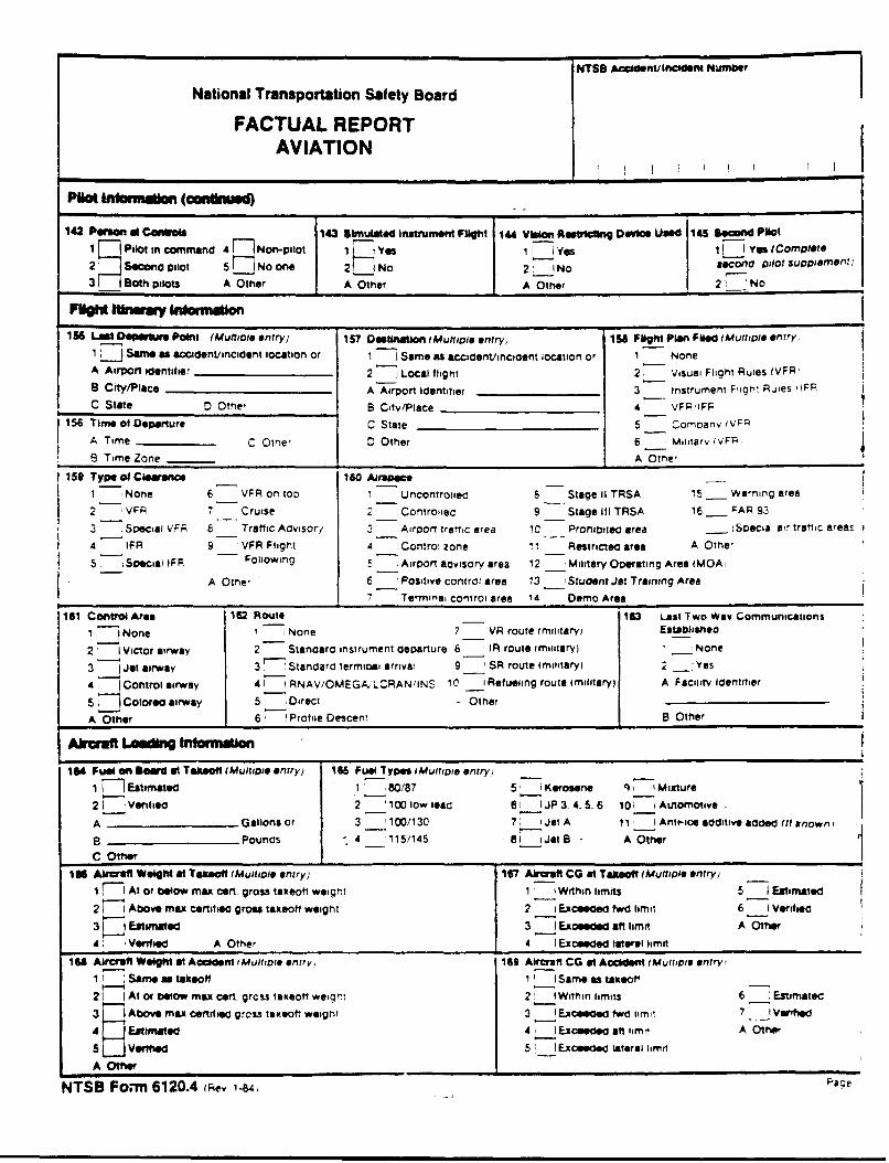
National Transportation Safety Board NTS6 Acdn ,r rlm Numtbir
FACTUAL REPORTAVIATION
Piot Intrmngion (mnxiued)
142 Person me CoOvedW 143 simulate Instrument Flight I"4 Vban RAtticig Device Used 145 110cond Plot1 F Pilot in command 4 F]7 Non-pilot I ~ 1YsiL- e L91 Yes (complete2 7 Scondpilot 5 EINo one 2J INo 2' ! No Coflo pilot supplement)
3 iBoth pilots A Other A Other A Other 2 No
156 Lat DePerwre Point (Muliple entry) 157 Destination lAMUhMoi entry; 158 FlIgh Plan Filed (Muliple entry
1 ~ Sine acidet/flidet ocaio o 1 Same as acciaentlincicent location or 1 NoneA Airport identifier ____________ 2 -jLocal flight 2- Visual Flight Rules IVFR,
B City/Place A Airport identifier ___________ 3 instrument Figaht Rules IFP
C State 0 Othe, B Citv/Place A-____________ VFR'IFP
16Time of Departure C State 5____________________ __
A Time C__________ Other 5 Comav iVF
S Time ZoneA6 h159 Type at Cleerance 160 Ai'uoace,
1 'None 6 VFR on top 1 Uncontrolled 8 Stage 11 TRSA 1I__ Warning area
2 -7VFR 7 Cruise 2 Controlied 9 Stage III TRSA 16 P AR 93
3 Special V.FF 8 Tratfic Advisory 2 Airport traffic area 10 Prohibited area ___Specia' air traflic areas
4 FR 9 VFR Filit 4 Control Zone I1I Restricted area A Othe,
5 7 Special IFR Following 5 Airport advisory area 12 __Military Operating Area iMOA,
-A Other 6 Positive controf area 13 __1 Student Jet Training Area
7 Ternei control area 14 'Demo Area161 Control Ara 162 Route13 LatToWyCmuiton
1 1Nn oe7 VR route tmiltaryl Eatabisheo2 1 Victor airway 2 Standea instrument departure 8 IR route (military) 1 1None
3 Jet airway 3 Standard terminael arriva 9 SR route (military) 2 'Yes
4, Control airway 4u 1 RNAv/OMEGAkLCRAN/INS IC __ Refueling route (military) A Facility Identifier
s T Colorea airway 5 Direct - Other
AOther 6 'Profile Descen' B Other
164 Fuel an Dowd at Takeo"f (M~ultiple entry) 165 Fuel Types lMultioie entry,1 Estimated 1 80/87 51 'Kerosene q7' IMixture
2 IlVenf led 2- 100 low ieda 8! JR 3.4.5.6 10' iAutoinotiva
A ___________Gallons or 3 '100/130 7 _'Jet A 11, Ante-ce additive added (it linown',
B __________Pounds -4 -'115/145 a ljeta - A Other
1686 Akrcraft Weight at Takeoff (Multiple entry) 167 Am CG at Takeoff lMulliple entry) _
17f1 At or below max cert. gross takeoti weigr.'- 1 Within limits 5 IEstima~ted21 1 Above max certif ie gross takeoff weight 2 1Exceeded twd limit 6 -1Verified
3 -JEstimated 3j Excede aft limit A Other
4 1 Verified A Other 4j xcee lateral limit
166 Airift Weight at Axel-ent A~ultiole entry) 169 Alircraf CG at Accden VMumtoiC oniryp
II I Same me taieof I' I Sam as tkefl
217 At or below max cen- gross isaceofi weigrrt 2 _1_ Within limits 6 -1Estimated
3 bove max certified gross taxeciff weight 3 -1 Exceeded fwd limit 7 -- I Vu'fie
4 mateod 4 ,lExceeoddaft limi A Other
5 Verthd5! lEzceoemc lateral limit
NTSB FormI 6120.4 (Fiev 1-84, Pag~e
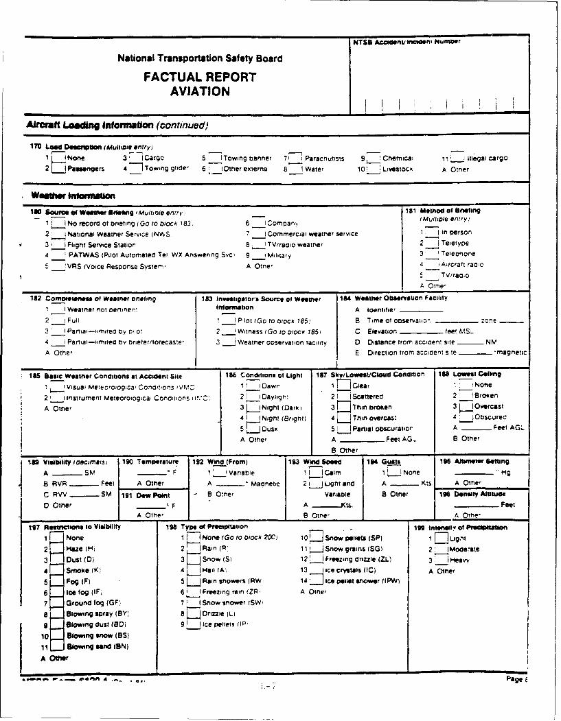
NTSB Acclaretlnadlinimtumoer
National Transportation Safety Board
FACTUAL REPORTAVIATION
Aircraft Lading Intarmation (continued)
170 Load Description (Muliple entry)
1 I(None 3 ICargo 5 7'rowing banner 7! 1 Parachutists 91 Chemical 11L-.J mllegal Cargo
2 JPassengers 4 (7Towing glide' 6 jOter externa 8: 1 Water 10! Livestock A Otner
100 Source of Weelfter Sitetung 'Mulioie entry 181 Method of Bri@4ingI L1 No record of biriefing (Go to block 783. 6 I comoan IPMUltDle entry)
2 ( National weatner Service (NW'S, 7 -1Commercial weather service 1. Inl person
3 !J Flight Service Station 8 I1 TV/radio weatner 2 Teletype
4 iPATWAS (Pilot Automated Tel WX Answering Svc) 9 __ililiary 3' iTelecirtone
5 __1IVRS (Voice Response Systerni A Otner 4 -I Aircrat'radio5 1 TV/raclio
A Othe'
182 Compositins" of Weather Driefing 183 invesigators Source of Waser 184 Weather Obsation faciitiy1! 1'Weatner not cieineri iformationl A Ioentifaer
2't- Full 1 Pilot (Go 1o block 185, B Time of observauco. - -one
3 ' - Paria-mmatea by oilot 2 _'Witness t Go to olocK 185) C Elevation - feet MIll
4 ___ Partiai-limitea by brieter/torecaste' 3, ___ Weatner oservatin faculity D Distance from accaen: site -____ NMA
A Other E Direction from accident stie - maonetic
185 Basic Weather Conditions at Accident Site 186 Conlditionis of Light 187 Sky/Lowest/Ctoud Condition 1M Lowest Ceiling1 I Visual Meieoroiooca Condlitions t 1NCi Dawn I F Cea r !None
2! instrument Meteoroiogical Conditions i i.C; 21 1Dayligmi 21 Scattered 2! 'Broken
A Other 3 jNight (Dark) 37 hnboe 3~~~cs
4A INight (Bright) 4 L_ Thin overcast 4 O1bScuredl
5TDusk 5! 1_ Partial obscuratior A -____Feet AGL
A Other A _ ___Feet AG- B Other
________ ______ B Other __________________
lgvisibility Idecimals, 190 Temperature 192 Witnd (From) 193 Wind Speed 194 Gusts 195 Muter Setting
A ____SMV ___ F 1' Variable 11i Cairm 1 L~JNone HMg
8 RVR -___Feet A Other A ____Maonetic 21 1 Light and A -___ Kts. A Other
C RWV - SM 191 Dew Pain' I B Other Variable B Othrie 196 Density Attitude0 Other -___ F A JKts. ______Feet
A Other B Other AOrme,
197 Riestrtctions to Visibility 198 Type ofPreciptition 199 Inesit of PrecipittltoriI None I ~None (Go to wock 200. 10I Snow pellets (SP) I DLsgmt
2 Maze (H, 2 (Rain (P 11 ~.JSnow grains (SG) 2! 1__Moderaste3 Dust (D) 3 Snow (S) 12.- Freezing dnrize (ZL) 3' _i,.Heavy4 Smoke (K) 4 HJ ail (Ai 13 1 Ice crystals (IC) A Other5 Fog (F) 5 Rain snowers fRWi 14 7Ice pellet shower I IPW(
6 ice fog (F, 61 1__Freezing rain (ZR A Other
7 Ground fog (GF) 7 (Snow snower (SW
a Blowing spray (BY) 8 k Drize (LI
o Slowing dust (SDI 9 ice pellets IlIP,
10 allowing show (s)
11 Slowingsandw(ON)
A Other
*'A CA.. , PageE
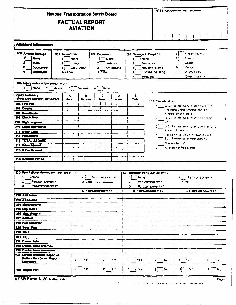
NTS8 Acwidnvncident NumberNational Transportation Safey Board
FACTUAL REPORTAVIATION
20 Aem Dowmage 201 Aliemfi Fire 20 Exaplosion 203 Danmae to PropertolY 67 Airport facility
I oeIP oe1 Noe 7-1 N on Vr- rees2 io r-lg2 Ifligt 2:" Residence 8 1crops
3- ubntiai 31 On ground 3 Ongon 3 -i Rsoniiae 9 1_ nen'
41 'molid A Other A Otnmer 41 Commrrericial 0109 10 1_ Wires/ipoles
2011 Ink~ uez (Most critical injury)3 eiu aa1 E None 2 'iMinor 3- eiu aa
Slimy -umr A 8 IC D E(Efter only one, digit per blocik) Fataf 541trouj inor None Total 217 ClaHwtion
-u pi-lot S Fiecisterecl Aircra-, o- i. SoL o" C@10 ____ eriories and Possessions of20 .iN Skiclent - in__ rternationai Waiers
I 20111 Cho* Pilot I2 L) S Reoistefea Aircra: c- Foreic--- -~ -ifllI
1 210 Cabin AIenosmns -1 L S Peomsereo Acr ooeprateao, a1211 ofter C"e - orecon Qoerato'
212 pa.s"We . Fro TeseeoAca rSot;'Territories o, Possessons
I2V3 TOTAL ABOARD __r 21 06. A~inlt7 'Miila ry Aircra7
I 25 Oecosm Aircraft not Reoisterec
M111GAMITrYAL
22 PaM FailurwMamctson iMujuob entry) -pavoonim3221 Iflconict Pant 0.4u/hole entry,14 ,lavopnn 17 I I None 4 Part'comoonernt ss2-
21 Patfioiponem to A Other 2, lPerv.como~oneni x 1 A Omre' _____
3p ecomoonent N2 3 1 ftrucorrimnent a'A PartlComparientl 41 * PatVCoqnoonent #2 C Part/Comeeonent *3
22 ATA Cf
zm anmu*
ft3 TeW TiMe ___________
X1 TSI _ _ _ _ _ _ _ __ _ _ _ _ _ _ _ _
SCym Tebo______________ ______________ ______________
NNOlWOVDlsiti Repo" Yes 2 -No -1 Yes 2 No 12 NYso
ns@WM2 loIYs 2' No I ye- 2 1-1Nc
NTSB Form 612M.4 (Re
Related Documents