iEFIS/Odyssey/Voyager G2 ARINC INTEGRATION GUIDE 1 April 2014 1

Welcome message from author
This document is posted to help you gain knowledge. Please leave a comment to let me know what you think about it! Share it to your friends and learn new things together.
Transcript

iEFIS/Odyssey/Voyager G2 ARINC INTEGRATION GUIDE 1 April 2014
1

iEFIS/Odyssey/Voyager G2 ARINC INTEGRATION GUIDE 1 April 2014
2
TABLE of CONTENTS;
Section: Title ______________________ Page
A. OVERVIEW--------------------------------------------------------------------------------------- 3
B. Garmin 400/500W to Odyssey/Voyager & iEFIS (iBOX) wiring details------------------ 4
C. Garmin 400/500W ARINC Configuration Details-------------------------------------------- 7
D. Odyssey / Voyager ARINC Configuration and Setup Details------------------------------- 8
E. iEFIS ARINC Configuration and Setup Details------------------------------------------------ 12
F. Switching between ARINC or EFIS NAV, & between ARINC Route & Heading Bug-- 13
G. Garmin 400/500W ARINC EFIS Logic with iEFIS or Odyssey/Voyager------------------ 14
H. Garmin 400/500W ARINC Turn On and BIT tests--------------------------------------------- 18
I. EFIS and Garmin 400/500W normal operations via ARINC Communication-------------- 19
J. EFIS Autopilot Operations using and Garmin Roll Steering (Internal/External A/P------- 23
K Emergency Operations------------------------------------------------------------------------------ 24
L. EFIS display options-------------------------------------------------------------------------------- 24
I. Summary--------------------------------------------------------------------------------------------- 25
Appendix A: ARINC Integration Issues------------------------------------------------------------- 26
Appendix B: ARINC File Playback inn the EFIS Simulator------------------------------------- 27
EFIS System Applications: This ARINC Integration and Operation Guide applies to MGL G2
iEFIS and G2 Odyssey/Voyager to GARMIN 400/500W series units. This guide is based on the
iEFIS G2 A1.0.2.1 (Jul13) and Odyssey/Voyager G2 SW Release G2 1.110 (Jul13). The
graphics are based primarily on the use of Default Screens.
This guide prepared for the MGL Users Group by Cecil Jones
RV-6A MGL Odyssey G2 & iEFIS,
G430W, NavWorx ADSB

iEFIS/Odyssey/Voyager G2 ARINC INTEGRATION GUIDE 1 April 2014
3
A. OVERVIEW
The iEFIS and G2 Odyssey / Voyager MGL EFIS displays among other external systems
are also integrated via the ARINC 429 interface with the GARMIN G400/500W series avionics
units. The ARINC integration provides the iEFIS and Odyssey/Voyager with a FAA approved
IFR certified GPS/WAAS navigator that provides global enroute and precision terminal Lateral
and Vertical approach navigation, and in some models both VHF communications and VOR/ILS
navigation and precision approach capabilities.
The primary function of the G430W is to provide FAA approved IFR GPS, Localizer, &
VOR Lateral Enroute and Terminal guidance and Lateral + Vertical approach guidance for
ARNAV/GPS and ILS approaches. The G430 also provides navigation guidance in the form of
course and waypoint information. Both the approach and navigation guidance is passed via
ARINC to the EFIS. During integrated ARINC operations the GARMIN at the option of the
user may provide its GPS navigation present position, ground track, and ground speed to the
EFIS, or as we have found out the iEFIS & G2-Odyssey/Voyager internal GPS present position
function supports the MGL autopilot operation much better due to its tight integration with the
MGL Autopilot. Also during integrated ARINC operations the EFIS provides Magnetic
Heading, pressure altitude, True Airspeed, Outside Air Temperature and “VOR” Course Select
(OBS) information back to the G4500/500W avionics. All G400/500W Mode/function changes
are selected through the GARMIN CDI Key which changes the system between “GPS” Enroute,
Terminal or ARNAV based approaches to “VLOC”, by selecting VOR based route navigation or
VOR, ILS, or Localizer based approaches. The EFIS displays the current navigation and
approach modes also selected by the CDI Key. At start up only the Garmin Bit test will display
on the EFIS until a valid route has been selected on the Garmin. Current EFIS SW requires the
Pilot to select “NAV” “Use External NAV Source” during startup to ensure that the G430
ARINC data provides the active route input into the EFIS. The EFIS will then receive and
display the G400/500 route (Flight Plan/Approach) as selected by the CDI Key on the Garmin
Navigator. The EFIS in GPS mode will receive and display GPS navigation and approaches
routes, and approach lateral and vertical guidance. In the VLOC Mode the EFIS will switch
between VOR or ILS display modes by following whether the pilot has selected a VOR or
ILS/Localizer frequency on the Garmin display, and will then only display this information on
the EFIS if the Garmin Navigation is receiving a valid VOR or ILS signal. During VLOC Mode
the Garmin still generates GPS/ARNAV route information with waypoints, this rout data is
displayed on the EFIS.
Physical integration between the G430/530W and the iEFIS (iBOX) and
Odyssey/Voyager requires only 6 wires (or 4 if the Garmin G400/500W or G420/520W has no
ILS/VOR receiver installed), 2 each ARINC twisted pair TX wire pairs connect the Garmin GPS
and NAV (VOR/ILS) receivers (TX-Out) to the iBOX or Odyssey ARINC “RX-IN” Ports 1 and
3 respectively (ARINC RX Port 1 only if No VOR/ILS receiver).
For autopilot operations the EFIS can use the GARMIN navigation routes/waypoints and HSI
needle outputs to drive the MGL internal EFIS autopilot or can provide the pilot the option to use
the G400/500 ARINC Label 121 (roll-steering) autopilot output to provide direct EFIS Lateral
autopilot guidance. Using Label 121 will allow the MGL autopilot to fly a complete Garmin

iEFIS/Odyssey/Voyager G2 ARINC INTEGRATION GUIDE 1 April 2014
4
route or approach including holding patterns. The ARINC Label 121 message can also now be
passed through the EFIS to an external ARINC capable autopilot.
All ARINC system setup menus are selected using the iEFIS or Odyssey/Voyager menu
screens, and the G400/500W Maintenance mode. Once the systems are set up, switching from
normal EFIS operation to Integrated GARMIN operation is performed on the iEFIS or
Odyssey/Voyager via the “NAV” function switch and the “Internal” or “External” NAV Source.
Currently the EFIS “External” Nav source cannot Display or Track (via ARINC Needle outputs)
G400/500W IFR Holding patterns on the iEFIS or Odyssey/Voyager. But the holding patterns
are still displayed on the G400/500W screen and if the EFIS MGL Autopilot is using the Arinc
Label 121 (as discussed above) the autopilot should fly the depicted Garmin holding pattern.
Using the ARINC Label 121 should more easily support EFIS integration with older (Non-
WAAS) G400/500 units. Currently the iEFIS/Odyssey/Voyager treats all G400W route
segments as straight line points.
Additionally the iEFIS/Odyssey/Voyager includes an ARINC flight data recorder using the
Micro-SD or SD card which allows for a playback capability in the iEFIS and
ODYSSEY/VOYAGER simulator (can be used in either simulator).
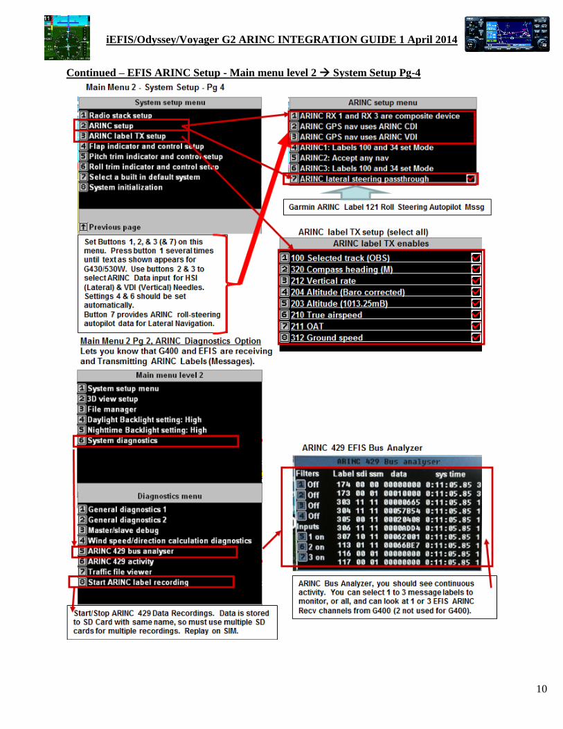
A) To record ARINC data on the Odyssey/Voyager goto Menu-2 “Pg-DWN” 9-
Systems diagnostics 9-Start ARINC label recording (or STOP as required)
B) To record ARINC data on the iEFIS select Menu “Pg-DWN” Systems diagnostics
“Pg-DWN” Start ARINC label recording (or STOP as required)
C) This recording can then be downloaded from the SD card and played back and or
analyzed using the EFIS simulator. This is very useful when designing IFR screens
useful for instrument approaches as you can test how different display designs will
present the same information, or this will allow you to re-fly (re-live) a flight or approach
worth remembering!! Detailed ARINC Simulator playback instructions are included
below.
B. Garmin 400/500W to Odyssey/Voyager & iEFIS (iBOX) wiring details
ARINC 429 is the predominant data bus used by commercial and business aircraft today.
The ability of the iEFIS/Odyssey to use ARINC 429 to communicate with the GARMIN
400/500W series avionics for 2-way data communications brings a level of sophistication not
commonly found in the cockpits of Experimental Aircraft. As described above the G430/540W
requires 6 ARINC 429 wires (3 pairs) to connect the iEFIS (iBOX) and Odyssey/Voyager
ARINC interface to the GARMIN unit. ARINC 429 uses unidirectional transmission of 32 bit
words (called Labels) over 2 wire twisted pair cables. The ARINC unidirectional data bus is
transmitted at either 12.5 or 100 kilobits per second. While the iEFIS (iBOX) can operate at
either speed, this integration uses the 12.5 kilobits per second or Low Speed ARINC mode since
this speed is more than adequate for the required ARINC communications.
Notes; (1) NO ARINC input is required into the Garmin P4006 NAV connector as
needed EFIS to Garmin NAV communications is available through the Garmin P4001 GPS
connection. (2) While not required these twisted pair cables are best installed shielded with
“Only One End of the Cable Shield Grounded”. When wiring up the ARINC connectors it is
best to not unwind more than about 2 inches of the twisted pair from each end of each of the
cable, this helps to minimize possible EMI on the data connection.

iEFIS/Odyssey/Voyager G2 ARINC INTEGRATION GUIDE 1 April 2014
5
A) Odyssey/Voyager: GARMIN shows these twisted wire pairs as A and B while the
Odyssey/Voyager ARINC connection shows RX1+ and RX1-. The GARMIN A connection
corresponds to the Odyssey + connection, B to -.
The 3 (or 2) ARINC twisted pair wire data cables connect the iEFIS (iBOX DB25
female) & Odyssey/Voyager ARINC (DB-9 female) connectors to the Garmin P4001 GPS
connectors (all G400W/500W units) and Garmin P4006 NAV connectors (G430W & G530W
only).
Connect as follows;
ODYSSEY/VOYAGER to GNS-400/500W ARINC 429 Interconnect
GARMIN GPS P4001 (78 Pin Connector) to Odyssey ARINC DB-9 (all G400/500W)
GPS ARINC Out A (Pin # 46) Odyssey RX1+ (Pin #2)
GPS ARINC Out B (Pin # 47) Odyssey RX1- (Pin #7)
GPS ARINC In (1) A (Pin # 48) Odyssey TX1+ (Pin #1)
GPS ARINC In (1) B (Pin # 49) Odyssey TX1- (Pin #6)
GARMIN NAV P4006 (44 Pin Connector) to Odyssey ARINC DB-9 (G430/530W)
VOR/ILS ARINC Out A (Pin # 24) Odyssey RX3+ (Pin #4)
VOR/ILS ARINC Out B (Pin # 23) Odyssey RX3- (DB #9)
GNS-400/500W to ODYSSEY/VOYAGER ARINC wiring diagram

iEFIS/Odyssey/Voyager G2 ARINC INTEGRATION GUIDE 1 April 2014
6
B) iEFIS (Discovery-Explorer-Challenger); Connect your iBox ARINC receive connections 1 &
3 and single ARINC TX connection as shown below to your Garmin GNS 400/500 series
avionics. Note early iBox software had the ARINC Receive (A/B) connections backwards, this
issue has been corrected and should be wired as shown below.
iEFIS (iBOX) to GNS-400/500W ARINC 429 Interconnect
GARMIN GPS P4001 (all G400/500W - 78 Pin Connector) to iEFIS → iBOX ARINC (DB-
25)
GPS ARINC Out A (Pin # 46) Pin#4, (iBOX – 1A) (iBox Pin# 4 is now correct)
GPS ARINC Out B (Pin # 47) Pin#3, (iBOX – 1B) (iBox Pin# 3 is now correct)
GPS ARINC In (1) A (Pin # 48) Pin#1, (iBOX – TA) (Correct on iBOX)
GPS ARINC In (1) B (Pin # 49) Pin#2, (iBOX – TB) (Correct on iBOX)
GARMIN NAV P4006 (G430/530W - 44 Pin Connector) to iEFIS → iBOX ARINC (DB-25)
VOR/ILS ARINC Out A (Pin # 24) Pin#8, (iBOX - 3A) (iBox Pin# 8 is now correct)
VOR/ILS ARINC Out B (Pin # 23) Pin#7, (iBOX - 3B) (iBox Pin# 7 is now correct)
iBOX to GNSZ00/500W ARINC wiring diagram

iEFIS/Odyssey/Voyager G2 ARINC INTEGRATION GUIDE 1 April 2014
7
Garmin 400/500W ARINC Configuration Details
Tobegin G400/500W configuration enter Maintenance Mode by pressing and
holding the ENTER key during POWER ON
sequence, then go to;.
“MAIN ARINC 429 CONFIG “ Menu
In 1 LOW EFIS/AIRDATA
In 2 Low Off
Out Low GAMA 429 (or
ARINC 429 Graphics)
SDI Common (SDI = 0)
VNAV Enable Labels (Allows GPS Vertical NAV
“MAIN CDI/OBS CONFIG”
CDI GPS Only
OBI Source ALWAYS GPS
“VOR / LOC / GS ARINC 429 Config”
menu
SPEED RX: LOW TX: LOW
SDI Common (SDI = 0)
DME: N/A

iEFIS/Odyssey/Voyager G2 ARINC INTEGRATION GUIDE 1 April 2014
8
D. Odyssey/Voyager ARINC Configuration and Setup Details
1. To configure the Odyssey/Voyager unit first turn the Odyssey/Voyager on and put it into
normal operations. Text description below is duplicated in the screen shot diagrams that
follow the text. Press Menu twice to select “Main menu level 2”;
In Main menu level “2”, Select Down Arrow (Page 2) “then button 1” System setup menu”
A. On Pg 2, as an option select “Setup Navigation” then select recommended mode
of Draw airspace over raster map, then on Page2 you have the Option of (Button 3) for
GPS-HSI to always point at the next waypoint, or GPS-HSI to be Locked to the GPS-
OBS . Press Menu once to back out to System setup menu
B. Select “Setup GPS & NEMA port ops”, here is the option to use the “Use Internal
GPS” from the Odyssey/Voyager GPS, or ”Use external GPS on ARINC channel 1”
(G400 GPS via ARINC). For best Odyssey/Voyager Autopilot operation it is
recommended to use the Internal GPS, for simulator setup select External GPS on
ARINC Channel 1”. This selection does not affect FAA requirements for use of the
G400 for IFR flight as the G400 still uses its Internal GPS to provide all courses and
approach guidance. Press Menu once to back out to System setup menu
C. Select “ARINC setup” press button 1 until it says “ARINC RX 1 and RX 3 are
composite device”. This is required for G430/530 ARINC integration using 2 Odyssey
RX channels (1 & 3) as shown in the included wiring diagram. For G400/500W with No
VLOC receiver then set up accordingly for Odyssey RX channel (RX 1). press
buttons 2 to select “ARINC GPS nav uses ARINC HSI” and button 3 to select ”ARINC
GPS nav uses ARINC VDI”, This sets the ARINC Data input for the EFIS HSI (Lateral)
& VDI (Vertical) Needles. If these buttons are not set correctly then you will not get any
GARMIN ARINC data to drive your route the or Lateral and Vertical Approach Needles.
Settings 4 & 6 should be set automatically. Setting 7 is optional depending on what type
of autopilot you have and how you want the G400/500W to drive it. Since the
Odyssey/Voyager can now process the G400/500 ARINC Label-121 roll steering
message to drive the Lateral guidance for the internal autopilot it is recommended setting
7 “ARINC lateral steering passthrough” be checked (Red Check).
D. Press Menu once to return to System setup then press “ARINC label TX setup”. Make
sure Labels 100, 320, 212, 204, 203, 210, 211, and 312 are all selected. Press Menu to
back out to normal EFIS screen.
E. Press Menu once to return “Main menu level 1”, then select function button “F1”
(NAV) Button “6”, until it reads “Using external NAV source” (Garmin must be
running with a route enabled). This concludes ARINC setup for the Odyssey. Press
Menu once to back out to normal EFIS screen.

iEFIS/Odyssey/Voyager G2 ARINC INTEGRATION GUIDE 1 April 2014
9
To Begin - Odyssey/Voyager ARINC Setup - Main Menu level 2 System Setup
iEFIS/Odyssey/Voyager G2 ARINC INTEGRATION GUIDE 1 April 2014
10
Continued – EFIS ARINC Setup - Main menu level 2 System Setup Pg-4

iEFIS/Odyssey/Voyager G2 ARINC INTEGRATION GUIDE 1 April 2014
11
After EFIS & Garmin have booted up & BIT check is complete Select & Load Garmin FPL (FlighPlan/Route)
Select “F1”-NAV Function key, & Select “Using external NAV source”, EFIS will then use Garmin Route
To view Garmin ARINC route (after Garmin route has been activated and external NAV source
has been selected, follow directions below.

iEFIS/Odyssey/Voyager G2 ARINC INTEGRATION GUIDE 1 April 2014
12
E. iEFIS ARINC Configuration and Setup Details
1. To configure the iEFIS units first turn the iEFIS on and put it into normal operations.
Text description below is duplicated in the screen shot diagrams that follows the text.
A. Press MENU – System setup menu Dwn-Arw Setup Navigation
Dwn-Arw HSI heading source is GPS if available : GPS Gnd Track for
heading (needed for Simulator ARINC Playback - Recommend for A/C)
B. Press MENU – System setup menu Dwn-Arw Setup GPS/NEMA Port
ops External ARINC GPS (for Simulator Only) or Internal GPS Only
(recommended for A/C) (EFIS using internal GPS for present position does not
affect IFR certified output of G400/500W, it computes its approach guidance
based on its own internal GPS WAAS Navigation solution)
C. Press MENU – System setup menu Dwn-Arw X2 ARINC Setup
ARINC RX1 & RX3 are Garmin G400/500 D. Select iEFIS “NAV” Function Button Using external NAV source
E. To check Active ARINC Route Select iEFIS “ROUTE” LIVE Flightplan

iEFIS/Odyssey/Voyager G2 ARINC INTEGRATION GUIDE 1 April 2014
13
F. Switching between ARINC or EFIS NAV, & between ARINC Route & Heading Bug
1. Once the EFIS has been configured for Integrated ARINC operation you have the option
of switching between G400/500 (ARINC) or internal EFIS commanded routes and
HSI/Glideslope approach guidance via onscreen menus, and between ARINC directed
Autopilot operation or Pilot selected vectors NAV (Heading Bug). These selections can
be made or changed at any time, but to keep cockpit operation simpler once a NAV
source has been selected (External or Internal) its recommended to stay with this
selection. This integration guide assumes the pilot is using the Garmin for his route and
approach operations, and the decisions will be to use vectors (manual Heading Bug) or
ARINC route/approach guidance and whether the autopilot is engaged or not. But the
internal EFIS GPS route option remains available for secondary or emergency purposes.
D. IMPORTANT: To use Garmin for ARINC Route input select EFIS Route
Menu. (“Shift” 4 “Route” or Function 1-NAV, then select “Using external
NAV source.
E. Normal Flt operations: Graphic shows option for Autopilot operation
between HBUG (vectors) or G430W ARINC Route.

iEFIS/Odyssey/Voyager G2 ARINC INTEGRATION GUIDE 1 April 2014
14
G. Garmin 400/500W ARINC EFIS Logic with iEFIS or Odyssey/Voyager
1. GARMIN 430/530WAAS navigation and instrument approach operations center around
three functions, first is finding and tracking enough GPS (& WAAS) satellites to provide
a precise 3-D navigation fix for WAAS navigation calculations and if selected an
acceptable VOR/ILS signal for conventional radio navigation, second is selecting and
entering a route, either a user created/stored route, or an Instrument Procedure (arrival or
departure) also represented in the EFIS unit as a route, and the third operation is the
navigation or use of GPS position to navigate the selected route. This guide assumes the
pilot is familiar with how the Garmin 400/500W works to include loading and selecting
waypoints, routes, and approach/departure procedures. Once a route or procedure has
been loaded and activated the pilot two primary controls on the GARMIN 430/530W to
control which navigation data is transmitted to the EFIS, first is the Garmin CDI Key,
and second is the NAV – VLOC Frequency selector button.
2. When the EFIS is in ARINC NAV mode the GARMIN produced route becomes the
active EFIS Flightplan route (assumes “External NAV source” has been selected, see
section E). All changes to the active GARMIN route including selection and activation
of an IFR approach will be automatically processed and displayed on the EFIS display.
The ARINC route will also be stored and can be displayed. On the iEFIS Select ROUTE
Live Flightplan, on Odyssey/Voyager select “Shift” “(4)-Route” ”(1) Live
Flightplan”,
3. Live Flightplan will show each
route waypoint, Course
(True&Mag), leg fuel, plus ETE
and ETA. This GARMIN
provided route is called “ARINC
route”. But unlike EFIS routes
ARINC routes “Cannot” be
changed or saved by the EFIS.
All route changes in ARINC
mode must be performed on the
Garmin.
A. If “External NAV source” has been selected for the Navigation input then current
Garmin position, ground track, ground speed, etc. will be provided through the
ARINC input to the EFIS, but the recommended setup is to use the EFIS Internal GPS
for improved Autopilot operation.
4. During IFR flight it is important to keep Pilot switch actions to a minimum; this reduces
the opportunities for switch confusion when using complicated electronic displays and to
optimize Pilot-Vehicle Interaction. A primary goal for G400/500W MGL EFIS
Integration is to keep switchology as simple as possible. With this in mind the pilot
selects the navigation or approach information source by using the Garmin G430/530W
CDI Key, this single switch action also directs the EFIS as to which of the ARINC
approach modes (GPS or VLOC) has been selected on the Garmin and should then be
displayed on the EFIS HSI and Glide Slope. Once an approach mode is selected no data
HSI/VSI course data will be displayed on the EFIS unless actual ARINC Navigation data
is being received from the Garmin. EFIS NAV/Approach examples are shown next;

iEFIS/Odyssey/Voyager G2 ARINC INTEGRATION GUIDE 1 April 2014
15
5. EFIS NAV/Approach examples are shown above;
A. If the VLOC mode is selected on the Garmin CDI Key then the EFIS looks to see
if the VLOC frequency is either a VOR or ILS frequency and if there is ARINC
data.
B. If External NAV source (ARINC) data is selected and being received, and the
Garmin CDI Key is set to GPS, but No GARMIN route has been selected on the
Garmin (FPL is blank), then the text NO CDI will appear in the middle of the
EFIS display, or depending on screen design, the HSI will not be displayed at all
and No Route will be displayed on the EFIS Map. If the Garmin CDI Key is set
to VLOC, but there is still No active ARINC route from the Garmin (FPL
remains blank), and NO ARINC VOR or ILS data (signal) being received, then
the text NO CDI will appear or No HSI display will be present. With the Garmin
CDI Key set to VLOC, but No VOR, or ILS signal is being received the EFIS
will still receive and display Garmin route waypoints, but will show No HSI
Course information because the course information is expected to come from a
valid VOR or ILS signal. Changing the CDI Key back to GPS would then show
the HSI GPS route or approach course again.
C. MGL screen designs will determine exactly what information will/or will not
appear during Garmin operation. But with most EFIS default Screen Designs the
basic VOR, ILS, or GPS Needle indications should not be present if the Garmin is
not receiving a valid signal or computing a GPS route or approach. If good

iEFIS/Odyssey/Voyager G2 ARINC INTEGRATION GUIDE 1 April 2014
16
ARINC VOR information is being received, then a VOR radial pointer will
appear and point toward the VOR station, and (depending on screen design) VOR
Radial Text would show the Current VOR radial. The EFIS VOR-OBS knob and
TO/FROM text will be active (TO/FROM will depend on the OBS selected
course and screen design).
D. If GARMIN CDI Key is VLOC and an ILS NAV frequency is selected, but No
ARINC ILS data is being received then the EFIS will show the text NO CDI or
No HSI will be displayed. If good ARINC Localizer information is being
received then the HSI will show only a Blue Course Indicator and course needle
over the attitude indicator, if both Good ARINC Localizer and Glideslope data is
being received then the EFIS will indicate both Lateral and Glideslope
information as seen above. The EFIS ILS OBS course selector knob will be
active, and should be set to the active ILS course. The GARMIN should remind
you as to Final Approach Course via its DTK turn point text just before FAF
arrival, and the MSG indicator may Flash if the EFIS OBS is not set to the correct
course.
E. If GARMIN CDI Key is set to GPS, and a normal Garmin “Route” is active
(Garmin shows ENR or TERM in lower Left of screen above GPS/VLOC text),
then the HSI will show a Pink Course Line, there will be No large Blue Lateral
Steering Needle over the Attitude indicator, and
(depending on Screen design) there will be
alternating Text showing GPS/ENR or GPS/TRM
next to the HSI display window, On the iEFIS &
Odyssey/Voyager the HSI will auto rotate toward
the current magnetic course and the Lateral Course
will indicate if aircraft is left or right of the course
(OBS does not rotate the HSI in this GPS route mode). In ARINC operations the
HSI is controlled entirely by the Garmin ARINC data so no HSI scale is shown.
If you select the Garmin Default NAV window it will show you the current HSI
cross track scale. Normally it will be a 2.0 NM HSI scale (ENR) or 1.0 NM
(TERM), but NAV Default page will always give you the correct scale. This
course scale will change automatically during approaches for both the EFIS and
the G430 NAV Window. Since no Glideslope is
associated with routes no “GS” flag should be seen
on the VDI during Enroute Navigation. The VDI
will become “Active” when the Garmin receives a
valid glideslope signal, or a GPS approach with
Vertical Guidance (VNAV) has been initiated. If Flight Plan Parallel course is
selected (in Garmin FPL Menu) then the Garmin will send parallel course route
information to the EFIS (Right or Left), the EFIS will show this parallel route as
the same active route as seen on the Garmin (the original route can only be seen
on the Garmin). Garmin Parallel route is designed to keep multiple airplanes with
precision Enroute navigation flying the exact same route (same 10 foot cube).
F. If GARMIN CDI Key is set to GPS, and a Garmin Instrument Approach is
selected and activated this route will be sent and displayed automatically on the
EFIS as the active route. If the Approach includes any holding patterns they will

iEFIS/Odyssey/Voyager G2 ARINC INTEGRATION GUIDE 1 April 2014
17
be displayed only on the Garmin screen. Due to MGL ARINC SW processing
development priories only straight route segments are currently displayed on the
EFIS. All Garmin Instrument approaches whether GPS, VOR, or ILS will be
downloaded and displayed on the EFIS Moving Map as a normal EFIS route.
Specific approach unique route protocols have not been implemented yet, an
example is that during all approaches the Garmin identifies the runway
touchdown point as waypoint “RWxx” (RW17). The EFIS treats this waypoint as
a routine waypoint, and will give an arriving Waypoint alert at whatever distance
has been set for normal waypoints (like 1.7 NM).
G. The EFIS 2-way ARINC interface with the GARMIN also provides the
G400/500W with critical EFIS generated flight data. The EFIS OBS course is
provided back to the GARMIN during ILS and VOR modes, and must be set
correctly by the pilot for the VLOC approach course being flown during ILS and
VOR flight modes. The EFIS also provides Pressure Altitude, Outside Air Temp,
Magnetic Heading, and True Airspeed to the Garmin. When stationary on the
ground, the EFIS Magnetic heading will correctly orient the Garmin moving map
screen.

iEFIS/Odyssey/Voyager G2 ARINC INTEGRATION GUIDE 1 April 2014
18
H. Garmin 400/500W ARINC Turn On and BIT tests
At turn on the Garmin400/500W unit will automatically go into a BIT test routine. Goal
of the BIT test is to establish 2-way ARINC communications and check system with the EFIS
.
GARMIN; “INSTRUMENT PANEL SELF-TEST” or BIT (BUILT IN TEST)
EFIS: During G430W BIT (Built In
Test) EFIS HSI/GSI and GPS position
data should indicate your present
position, but will have the waypoint as
Garmin and will compute a distance to
the Garmin Headquarters in Kansas
(USA) from your present location.
ETA to GARMIN will be at a GS of
149K. HSI will show a Pink ½ Left
Course Error and GSI will show a ½
Course Low Vertical error.
NOTE: If there is NO ROUTE or HSI
display for the BIT then check function
switch “NAV” “using External
NAV source”, if not set correctly then
set to “external NAV”. When this
happens you must also Select GPS
lateral NAV” even though it will likely
already show as being selected select GPS lateral NAV “AGAIN”.
If BIT test is still not correct check the other EFIS and/or GARMIN interface settings. If there is
no indication of ARINC communications between the two units then check the EFIS ARINC
Bus Analyzer (shown below). If BIT test is successful then press the GARMIN “ENTER” key
and resume normal operations.

iEFIS/Odyssey/Voyager G2 ARINC INTEGRATION GUIDE 1 April 2014
19
I. EFIS and Garmin 400/500W normal operations via ARINC Communication
1. Cross Country Navigation using the Garmin 400/500W
Now for the fun stuff, using your EFIS as a smart display/interface with the GARMIN
G400/500WAAS COMM and Global Navigation units. Once the EFIS has been set up to
operate correctly with the GARMIN the EFIS is used for flying, navigating, situation awareness,
engine and fuel management, autopilot operations, and displaying approach information and the
GARMEN G400/500W is used for communications, route and approach selection and
management. Since both the EFIS and Garmin have moving maps, and additional GPS based
navigation data, either or both are available for pilot use, but IFR route and approach selection
and guidance should only be performed using the GARMIN. The GARMIN should also have a
current IFR data base for the area being flown if it is to be used for actual IFR Enroute and
Approach Navigation. If you need IFR training approaches that are not available in the
GARMIN/JEPPESEN data base the EFIS covers this capability in other parts of the instruction
manual.
After the BIT test, the pilot should program, or select and load the GARMIN route from the
GARMIN data base. Details on GARMIN route creation, storage, and activation are covered in
the GARMIN pilot’s manual. GARMIN operation is not changed when using the EFIS. This
can include SIDS (departure routes), ordinary cross country routes, STARS (Standard Terminal
Arrival Routes), and approaches. Using the FPL button and Cursor Knob on the GARMIN the
pilot selects the route, and after pressing the “ENTER” button this route is transmitted to the
EFIS for display and navigation. Since the GARMIN is an FAA-IFR approved WAAS
navigation system, it may be used for any type of Enroute or Approach Navigation, at most any
altitude, anywhere in the USA today, and in
most other countries with appropriate data bases.
In the figure to the left a 4 waypoint route has
been selected via the Garmin FPL (Flight Plan

iEFIS/Odyssey/Voyager G2 ARINC INTEGRATION GUIDE 1 April 2014
20
page), entered in the GARMIN, and transmitted to the EFIS. This figure shows the EFIS display
with the pilot navigating toward the 2nd
route waypoint (user waypoint FLD2). The pilot has set
the GARMIN navigation mode as GPS (selected by Garmin CDI Key) and is shown on the EFIS
as a Pink HSI course on the HSI course display. The OBS is set to the Track to Waypoint course
of 172 DegsM, but in GPS mode the OBS is automatically slaved to the GPS Gnd Track so
setting the OBS has no direct effect on navigation. To the right side of the HSI are the
alternating words GPS & TRM which indicates that the EFIS is displaying Garmin GPS
“Terminal” route information. Further along the flight in the screen shot below the HSI indicator
shows the aircraft to the right of the Garmin route 341 Deg course between FLD2 and KCEW,
the Ground Track shows 321 Degs which indicates the aircraft is tracking toward the next
waypoint (KCEW) but should intersect the 341 Deg course on this track prior to the waypoint.
Below the Map Display at the right of the EFIS screen you can see the KCEW waypoint
information, the Distance is 2.8 NM’s, the airspeed and GS (Ground Speed) are not shown on
this display, the ETE is 1:33 (min:secs) with the ETA to the final route waypoint (#4) as 22:17
(hrs:mins). As mentioned above, this graphic is an example of what the pilot may have available
if this or a similar screen design is used. To check the route progress the pilot selects (on iEFIS)
ROUTE Live Flight Plan, or Odyssey “Shift” “Route” then presses button “1” “Live
Flight Plan”. This brings up the “Live Flightplan: ARINC route” display screen that shows the
remaining 2 waypoints. Data displayed includes ETE, ETA, Course (True/MAG), and Fuel
information along the route. To return to normal screen display press “DONE” or the “ENTER”
Key.

iEFIS/Odyssey/Voyager G2 ARINC INTEGRATION GUIDE 1 April 2014
21
2. ILS Approach with GPS routing using the Garmin 400/500W
As the plane approaches the KCEW waypoint the pilot elects to shorten the flight and fly several
approaches at the Crestview, FL (KCEW) airport. Using the GARMIN FPL Key the pilot first
Highlights the KCEW waypoint (with the GPS rotary knob), then selects Direct KCEW
ENTER on the Garmin. This will change KCEW from the next waypoint to a destination. The
pilot then selects the Garmin PROC Key (Procedure) and scrolls through available KCEW
approaches and selects the ILS 17 approach. The pilot also uses the EFIS OBS to dials in the
“171” Deg ILS final Approach course. Once the Garmin ILS17 approach is “Activated” the
approach routing (waypoints) are sent to the EFIS as a new route, and are immediately displayed
on the EFIS map. If the ILS approach waypoints are not in the EFIS Navigation data there will
only be a course line to an un-named point on the map but this will not impact the EFIS route
display. The new
waypoint name will
appear on the EFIS but
the waypoint location can
only be seen on the
Garmin display. In the
example to the left the
pilot has selected VLOC
on the GARMIN “CDI”
Key, and has switched the
NAV receiver to the
KCEW ILS localizer
frequency, and finally
with the Garmin receiving a good ILS signal it is being displayed (both Localizer and
Glideslope) by the EFIS. All of this can be confirmed by looking at the HSI display which
shows a Blue Course line on the HSI display and the large Blue Localizer and Glideslope needles
superimposed over the attitude display. While a Garmin GPS/ARNAV overlay approach will
always be displayed (assuming good GPS signal availability), ILS or VOR approach’s requires
good ARINC signal data. Check section “F” for indications during loss of VOR or ILS signals.
Since both good ARINC HSI and VDI data is being received both the Localizer and Glideslope
are displayed. On the moving map displayed route you can see that the pilot has already passed
the FAF of “GIYAT”, and the aircraft is descending on the approach path to the airfield.
The HSI shows the aircraft on the Localizer course, and the Glidepath indicator (White
Circle) shows the aircraft very slightly above the Glidepath. The NAV Info window under the
map display on the EFIS screen displays the next approach waypoint as RW17, and the DIST to
the runway is 2.0 NM’s. All of this information comes from the GARMIN ILS-17 approach
route data base.
In the attitude display is the Large Blue Localizer and Glide Path Needles, knowing
exactly where the center of these needles are (On Course and Glidepath) can be a little difficult
at times so its recommended to also add a small Square at the center as a Target for the Needles.
If the flight path marker, DTED, and airfield data are correct, the pilot should see the ILS
Needles superimposed over the flight path marker and centered on the electronic touchdown
point over the approach end of runway during a correct stabilized approach.

iEFIS/Odyssey/Voyager G2 ARINC INTEGRATION GUIDE 1 April 2014
22
3. VOR Approach with GPS routing using the Garmin 400/500W
The pilot completes a touch and go from the ILS approach and elects to fly a 2nd
KCEW
approach, this time the VOR circling approach to
runway 17. Selection of this approach is again
similar to the previous approaches with the pilot first
confirming the CDI Key is still set to VLOC then
selecting and activating the VOR-A approach. The
GARMIN locates and loads the CEW VOR 115.90
MHz frequency into the Garmin VLOC standby
NAV frequency window, displays the VOR-A approach on the Garmin may display (as shown
above) and sends the VOR ARINC approach route to the EFIS also for display. The pilot must
then press the
Garmin VLOC
frequency Key which
moves the CEW
VOR frequency from
the standby to the
active NAV
frequency. The pilot
should then see the
EFIS HSI display go
active when the
Garmin receives a
valid VOR signal, the
Green EFIS VOR station indicator should point toward the VOR station. The pilot should set the
OBS indicator to the 106 Deg inbound VOR course and start the approach. This approach
begins with the pilot flying to the VOR station and then either entering holding or after a
procedure turn beginning the approach. On the EFIS you will see the Green VOR station
indicator at station passage swing from in front of the aircraft to behind the aircraft, the Garmin
will countdown the distance to the VOR station till it hits zero then the NOTME waypoint will
appear on the EFIS as the next waypoint, and the waypoint distance will indicate this new
waypoint. As mentioned before the holding pattern will only appear on the Garmin, but not the
EFIS. The EFIS display above shows both the CEW to Crestview GPS approach route (Red
dashed line) and the VOR 106 Mag course (Yellow solid line) as well as the Green VOR Station
locator (behind aircraft). At the end of this approach the pilot confirms he has Visual contact
with the runway environment and circles to the runway.

iEFIS/Odyssey/Voyager G2 ARINC INTEGRATION GUIDE 1 April 2014
23
4. GPS/ARNAV approach using the Garmin 400/500W
The pilot completes a touch and go from the VOR approach and elects to fly a 3rd KCEW
approach, this time the GPS ARNAV approach. Selection of this approach is nearly the
same as the VOR approach except the pilot
switches from VLOC to GPS using the
Garmin CDI Key, then selects and activates
the GPS ARNAV 17 approach. The
GARMIN sends the approach route
(waypoints) to the EFIS and the pilot gets an
alert message on the EFIS announcing a new
“ARINC WP Active: GIYAT”. The Pilot
then fly’s the ARNAV 17 Approach similar
to the ILS 17 approach. If the pilot selects
Vectors there will be a course displayed on
the EFIS to the FAF (GIYAT) but the
routing will likely be by ATC vectors before flying toward GIYAT. An additional option is
to select and fly to the IAF to initiate the approach, for this approach WEDOM would appear
as the next waypoint on the EFIS route and from the KCEW airport the Garmin would
provide a procedure turn available only on the Garmin display north of the WEDOM IAF to
reverse direction back toward the GIYAT FAF and place you on the GPS 17 approach. At
the end of this approach the pilot makes a full stop landing.
J. EFIS Autopilot Operations using and Garmin Roll Steering (Internal/External A/P):
1. EFIS Autopilot Operations:
The MGL autopilot can either track the HSI lateral steering needle or if selected in AP
setup it can now follow the Garmin roll steering commands provided by the ARINC
Label 121 message. Roll steering is more correctly called GPSS (GPS Steering). Using
GPSS allows the Garmin 400/500 to drive the AP directly vs. driving the HSI which then
drives the AP. In GPSS mode the Garmin directs the MGL AP through GPSS commands
to stay on the Garmin programmed route or approach by anticipating waypoints (as
shown in the graphic to the left) and will lead turn most waypoints with smooth turns to
arrive back precisely on your next flight leg on course with a wind corrected heading.
The big advantage is for flying complex flight plans including holding patterns and
procedure turns (and likely perfectly), all using the Garmin (Jeppessen) data as depicted
on the Garmin display. GPS/ARNAV approaches should be able to be flown
"automatically" without
having to touch vector
(HBUG) mode or the stick
(manual) mode. Using
GPSS for AP steering you
can potentially start the AP
after takeoff and
disconnect at landing. The
pilot would select the
Garmin 400/500 route and the Garmin would compute the flight plan and provide the

iEFIS/Odyssey/Voyager G2 ARINC INTEGRATION GUIDE 1 April 2014
24
GPSS AP commands with all heading changes to the MGL A/P for the entire flight.
Using the HSI for tracking a NAV source (the previous way), the autopilot can act in less
desirable and often unpredictable ways (you can be surprised, or as I have seen the AP
can act up so badly it will disconnect itself) usually when flying over waypoints. GPSS
works by providing the AP with the rate of turn that is required to make the desired turn.
2. A/P Setup with Garmin G400/500:
If the MGL (internal) A/P is used: With external ARINC navigation selected, the internal
AP will use the Garmin supplied GPSS lateral
steering label 121 as cue (regardless of state of
the local HSI). Note: In ARINC setup you
need to enable lateral steering passthrough or else this is disabled. If this label is not
received valid, the AP will use the HSI. If the EFIS is setup for External A/P operation
then also in ARINC setup you need to enable lateral steering passthrough or else the
external A/P would use an EFIS internally generated GPSS label 121 steering cue which
would not support any Garmin holding patterns or procedure turns (only what can be
displayed on the EFIS moving map). In the NAV
menu for A/P operations you have two choices the
vectors (HBUG) mode directs the A/P to follow the
pilot commanded yellow Heading Bug as entered
via the “HEAD” rotary knob, or the Garmin Route
input either with the just discussed GPSS commands
or by the A/P following the HSI inputs also via the GARMIN ARINC labels.
K. Emergency Operations:
During Aircraft Emergencies its recommend to use the Garmin emergency Navigation functions
as designed. All emergency airfields or routes selected on the Garmin will transfer and operate
as normal waypoints on the EFIS. If the MGL EFIS internal GPS fails the Garmin GPS may be
used for navigation after the EFIS GPS NAV Data Sources is switched back to the External GPS
on ARINC channel 1. If No GPS is available (loss of adequate GPS satellite signals) the Garmin
VOR receiver if still operating should still be able to send ARINC radial data to the EFIS HSI,
and the ILS could support ILS approaches, but NO Garmin ARINC Approach routes would be
available.
L. EFIS display options
The EFIS has an infinite number of EFIS display options since the pilot can create his own
displays. For normal VFR flight this is not an issue, but for IFR flight the display screens do
make a difference. It is critical that the IFR pilot acquire or create IFR display screens that
display required data in easily usable formats. The optimum EFIS screen will display all the
information a pilot needs to fly the airplane, monitor its critical engine and electrical systems,
navigate, and fly an approach in a single display. Screen designs that separate critical
information between multiple screens, or is confusing in any way, increase the possibility that
information mis-understandings can distract a pilot during critical phases of IFR flight and
compromise safety.

iEFIS/Odyssey/Voyager G2 ARINC INTEGRATION GUIDE 1 April 2014
25
M. Summary:
Despite all the extensive documentation and detailed discussion in this guide, once set up
correctly the MGL EFIS unit when connected via ARINC to the Garmin G4500/500W series
avionics should be intuitive to operate and will leverages the power and flexibility of the MGL
avionics to provide a new level of capability for the Experimental Aviator. This is the third
release of this manual and adds both the iEFIS display series along with the changes and
increased functionality provided by several significant SW releases. But as always Pilot in
Command is still responsible for ensuring the ARINC integrated screen displays, EFIS modes,
GARMIN approach and route types, and commands are adequate to before and flight and
especially IFR flight is attempted.

iEFIS/Odyssey/Voyager G2 ARINC INTEGRATION GUIDE 1 April 2014
26
Appendix A: Troubleshooting Integration using the Simulator - ARINC Playback function.
If after a careful setup the system does not work as it should use the ARINC Data Recorder to
record about 1 minute of G430W startup test Data. Then follow the ARINC Data playback
instructions in Appendix B and compare your recorded data with what’s shown below. Graphic
below shows correct Sim BIT indication for ARINC playback.
The following text example is from an integration with a good VOR ARINC connection and a
bad GPS connection; The SIM playback will show a “G” for Good data coming from the G430
into the EFIS. If you only see the G430W-VOR port OR ARINC out (P4006 #23 & #24)
providing good data then the VOR connection is good. Note: (Labels 34 (VOR-Freq will show
“G” during BIT but VOR labels 173, 174, 222 will show nothing during a BIT test, so if Label
34 is “G” then VOR is OK). But if the P4001 ARINC Out data is showing “F” (Failed) like
Label 100 then this port is likely at the wrong Speed (High instead of Low) or Not configured for
GAMA 429, or the A/B wires are reversed. Note: (label 117 may still show “G” with a P400a
Port issue). So using the G400/500 recorded BIT data and the Simulator you should be able to do
some good troubleshooting. If you have an issue start by double checking G430W Main ARINC
Configuration Page, trouble shoot from there to the EFIS. For questions contact me.

iEFIS/Odyssey/Voyager G2 ARINC INTEGRATION GUIDE 1 April 2014
27
Appendix B: Instructions for Recorded MGL Forum ARINC flights & Data
1. Download and Install current iEFIS or Odyssey/Voyager G2 Simulator
2. Create ARINC File in the iEFIS File Manager under Explorer SIM
3. Follow guide below and find Arinc_G430_Recorded Files (To download Recorded
ARINC data files from MGL Forum you must be Logged In). Copy the Recorded
ARINC Flight Data Files into the “ARINC_FlightData” folder you created (above) in
the Simulator.
4. Close the Simulator File Manager

iEFIS/Odyssey/Voyager G2 ARINC INTEGRATION GUIDE 1 April 2014
28
5. Select Sensor Simulation Menu
6. Select ARINC
Simulation
7. Then Look In
(Select) your ARINC
Flight Data Folder
8. Select a ARINC File
you want to replay
(its really not a
simulation, its a
actual recorded
ARINC Flight Data
File Replay)
9. Select Open --> This
actually starts the
Data File Replay
10. Most all these flights are around FtWalton Beach and Crestview FL, 1 file from Oshkosh,
several files from Torrance CA (USA MGL Office location), and the G430 BIT files are
near the Garmin Headquaters in Olathe KA.
11. To replay the ARINC files you must
have the iEFIS or Odyssey/Voyager
Simulation configured just like in the
aircraft. To setup for ARINC playback
follow sections D and E in this guide.
Some specific details most useful for the
Simulator follow; A) Menu-->Sys
Setup-->GPS NEMA Op--> External
ARINC GPS (use Ext ARINC GPS for
ARINC Sim Data Playback only-Not for
Flight, for Flt use EFIS internal GPS)
B) Menu-->Sys Setup-->Navigation
Setup-->Dwn Arow-->HSI Hdg GPS
C) From EFIS NAV Selection select-->
Use External NAV Source
12. Except for Bit Check which does not
move plane the Arinc Replay Files will
take the plane for a Simulated Flight
using recorded ARINC data with either
a route, or a GPS ARNAV (Lat/vert
Guidance), ILS (Lat/Vert Guidance) or
VOR approach (look up KCEW or other
Arpts to see the approach plates for
these approaches).
Related Documents