IEEE802.3 Open Revision Requests IEEE802.3 Open Revision Requests Order by Request Number Req# Status Standard Clause Date Subject 1105 B 802.3ae-2002 45.2.3.15.1 14-Nov- 02 Register cross reference error 1106 B 802.3ae-2002 30.3.2.1.5 20-Feb-03 Incorrect cross references 1107 R 802.3ae-2002 52.9.1.2 & 49.2.8 06-Mar- 03 Square wave test pattern definition 1108 E 802.3ae-2002 Annex 48B 30-May- 03 Jitter test methods 1110 B 802.3ae-2002 53.15.4.3 17-Aug- 03 Management Functions, item MR6 1111 B 802.3ae-2002 53.15.4.3 17-Aug- 03 Management Functions, item MR7 1112 E 802.3ae-2002 Various, see details 17-Aug- 03 PICS copyright release statement 1113 B 802.3ae-2002 45.2.3 17-Aug- 03 PCS registers 1114 B 802.3ae-2002 45.2.5.8 17-Aug- 03 10G DTE XGXS lane status register 1115 I 802.3-2002 23.7.1, 40.8.1 02-Oct-03 MDI Connectors 1116 E 802.3af-2003 Annex 33A 22-Oct-03 PSE Detection of PDs - Figure 33A.2 1117 B 802.3af-2003 33.2.3.7 31-Oct-03 PSE State Diagrams 1118 B 802.3ae-2002 48.2.4.2 31-Oct-03 Idle ||I|| file:///C|/web/3/maint/requests/open_num.html (1 of 4)7/14/2004 19:47:49

Welcome message from author
This document is posted to help you gain knowledge. Please leave a comment to let me know what you think about it! Share it to your friends and learn new things together.
Transcript

IEEE802.3 Open Revision Requests
IEEE802.3 Open Revision RequestsOrder by Request Number
Req# Status Standard Clause Date Subject
1105 B 802.3ae-2002 45.2.3.15.1 14-Nov-02
Register cross reference error
1106 B 802.3ae-2002 30.3.2.1.5 20-Feb-03 Incorrect cross references
1107 R 802.3ae-2002 52.9.1.2 & 49.2.8 06-Mar-03
Square wave test pattern definition
1108 E 802.3ae-2002 Annex 48B 30-May-03
Jitter test methods
1110 B 802.3ae-2002 53.15.4.3 17-Aug-03
Management Functions, item MR6
1111 B 802.3ae-2002 53.15.4.3 17-Aug-03
Management Functions, item MR7
1112 E 802.3ae-2002 Various, see details 17-Aug-03
PICS copyright release statement
1113 B 802.3ae-2002 45.2.3 17-Aug-03
PCS registers
1114 B 802.3ae-2002 45.2.5.8 17-Aug-03
10G DTE XGXS lane status register
1115 I 802.3-2002 23.7.1, 40.8.1 02-Oct-03 MDI Connectors
1116 E 802.3af-2003 Annex 33A 22-Oct-03 PSE Detection of PDs - Figure 33A.2
1117 B 802.3af-2003 33.2.3.7 31-Oct-03 PSE State Diagrams
1118 B 802.3ae-2002 48.2.4.2 31-Oct-03 Idle ||I||
file:///C|/web/3/maint/requests/open_num.html (1 of 4)7/14/2004 19:47:49

IEEE802.3 Open Revision Requests
1119 B 802.3af-2003 33.2.7.2 15-Nov-03
PSE classification
1120 B 802.3-2002 1.4 25-Nov-03
Definition of Type
1121 B 802.3-2002 28C.6 17-Dec-03
Message Code #5--Organizationally Unique Identifier (OUI) tag code
1122 B 802.3-2002 28C.7 17-Dec-03
Message Code #6--PHY identifier tag code
1123 B 802.3-2002 24.2.4.2 05-Jan-04 Transmit
1124 E 802.3-2002 Front matter 05-Jan-04 Introduction to IEEE Std 802.3-2002
1125 B 802.3-2002 24.8.3.2 10-Feb-04 PICS - PCS functions
1126 B 802.3-2002 26.4.1 10-Feb-04 Medium Dependent Interface (MDI)
1127 B 802.3-2002 3.2.3 10-Feb-04 Address Fields
1128 E 802.3-2002 36.2.5.1.4 & 36.2.5.1.3
1-Mar-04 Functions & Variables
1131 E 802.3ae-2002 4.2.7.1 10-Mar-04
Common constants, types, and variables
1132 B 802.3ae-2002 4.2.3.1 10-Mar-04
Transmit data encapsulation
1133 E 802.3ae-2002 4.2.8 16-Mar-04
Frame transmission
1134 R 802.3ae-2002 48.7.4.1 08-Apr-04
Compatibility considerations PICS
1135 B 802.3ae-2002 45.5.5.3 29-Apr-04
PMA/PMD management functions PICS
file:///C|/web/3/maint/requests/open_num.html (2 of 4)7/14/2004 19:47:49

IEEE802.3 Open Revision Requests
1136 B 802.3ae-2002 45.5.5.16 29-Apr-04
Electrical characteristics PICS
1137 B 802.3ae-2002 45.5.5.3 29-Apr-04
PMA/PMD management functions PICS
1138 B 802.3ae-2002 45.5 29-Apr-04
PICS for Clause 45, MDIO interface
1139 B 802.3-2002 1.4 21-May-04
Definition of CS0, CS1
1140 R 802.3-2002 5.2.4.2 21-May-04
Error in variable name
1141 B 802.3-2002 7.2.1.1.1 21-May-04
Formatting error
1142 B 802.3-2002 7.2.1.1.5 21-May-04
Mis-spelled word
1143 B 802.3-2002 Figure 7-6 21-May-04
Transition condition inversion missing
1144 B 802.3-2002 14.2.1.5 21-May-04
Typo in minimum value of range
1145 B 802.3-2002 14.2.3.2 21-May-04
Incorrect state name referenced
1146 R 802.3-2002 Figure 14-3 21-May-04
State transition error
1147 B 802.3-2002 Table 14-2 21-May-04
Text formatting error
1148 B 802.3-2002 Figure 27-1 21-May-04
Spurious text in figure
1149 E 802.3-2002 40C.1, 40C.2.1, andFig 40C-2
25-May-04
Missing variable definition
1150 B 802.3-2002 Figure 40C-2 25-May-04
State machine error
file:///C|/web/3/maint/requests/open_num.html (3 of 4)7/14/2004 19:47:49

IEEE802.3 Open Revision Requests
1151 R 802.3ak-2004 54.6.3.2 1-Jun-04 Test Fixture Impedance
1152 R 802.3ah-2004 64.3.3.2 8-Jul-04 Variable error
1153 R 802.3ah-2004 64.3.3.5 8-Jul-04 Message error
1154 R 802.3ah-2004 64.2.2.1 8-Jul-04 Constants error
1155 R 802.3ah-2004 65.2.2.2 8-Jul-04 Functions error
1156 R 802.3ah-2004 Figure 64-22 8-Jul-04 State machine error
1157 R 802.3ah-2004 Figure 64-21 8-Jul-04 State machine error
1158 R 802.3ah-2004 65.2.3.2.3 8-Jul-04 FEC Special frame markers lack of Hamming distance
Return to 802.3 Maintenance Requests Page Last Update: 07 Jul 04
file:///C|/web/3/maint/requests/open_num.html (4 of 4)7/14/2004 19:47:49

1105 - 1ISO/IEC 8802-3/IEEE Std.802.3 Revision Request. Subject to change.
123456789101112131415161718192021222324252627282930313233343536373839404142434445464748495051525354
+----------------------------------------------------------------------+| 8802-3/802.3 REVISION REQUEST 1105 |+-----------------====================================-----------------+
DATE: 14th Nov, 2002NAME: Naresh RamanCOMPANY/AFFILIATION: LSI LogicE-MAIL: [email protected]
REQUESTED REVISION:STANDARD: IEEE 802.3ae-2002CLAUSE NUMBER: 45CLAUSE TITLE: 45.2.3.15.1
PROPOSED REVISION TEXT:
See below.
RATIONALE FOR REVISION:
The second and third occurrences of 3.32.2 in this paragraph need to be changed to 3.42.5 since it refers to this bit itself. The first occurrence of 3.32.2 is correct since it refers to the ability of the device in supporting PRBS31 pattern testing.
IMPACT ON EXISTING NETWORKS:
None. Cross reference errors.
+----------------------------------------------------------------------+| Please attach supporting material, if any || Submit to:- Bob Grow, Chair IEEE 802.3 || E-Mail: [email protected] || || +------- For official 802.3 use -----------+ || | REV REQ NUMBER: 1105 | || | DATE RECEIVED: 14th Nov, 2002 | || | EDITORIAL/TECHNICAL | || | ACCEPTED/DENIED | || | BALLOT REQ'D YES/NO | || | COMMENTS: 12-Mar-03 Ver: D1.0 Status: B | |+-------------+------------------------------------------+-------------+| For information about this Revision Request see - ||http://www.ieee802.org/3/maint/requests/revision_history.html#REQ1105 |+----------------------------------------------------------------------+

1105 - 2ISO/IEC 8802-3/IEEE Std.802.3 Revision Request. Subject to change.
123456789
101112131415161718192021222324252627282930313233343536373839404142434445464748495051525354
Change to ANSI/IEEE Std 802.3ae-2002, Clause 45EDITORIAL NOTES - This revision request is based on the current edition of IEEE Std 802.3ae-2002. The editinginstructions define how to merge the material contained here into this base document.
Editing instructions are shown in bold italic. Three editing instructions are used: change, delete, and insert.Change is used to make small corrections in existing text or tables. The editing instruction specifies thelocation of the change and describes what is being changed either by using strikethrough (to remove oldmaterial) or underscore (to add new material). Delete removes existing material. Insert adds new materialwithout disturbing the existing material. Insertions may require renumbering. If so, renumbering instructionsare given in the editing instruction. Editorial notes will not be carried over into future editions.
45.2.3.15.1 PRBS31 receive test pattern enable (3.42.5)
Change subclause 45.2.3.15.1 as follows:
If the PCS supports the optional PRBS31 pattern testing advertised in bit 3.32.2 and the mandatory receivetest pattern enable bit (3.42.2) is not one, setting bit 3.42.53.32.2 to a one shall set the receive path of thePCS into the PRBS31 test pattern mode. The number of errors received during a PRBS31 pattern test arerecorded in register 3.43. Setting bit 3.42.53.32.2 to a zero shall disable the PRBS31 test pattern mode on thereceive path of the PCS. The behavior of the PCS when in PRBS31 test pattern mode is specified in Clause49.
Editors� Notes: To be removed prior to final publication.
Revision History:Draft 1.0, November 14, 2002 Initial draft.

1106 - 1ISO/IEC 8802-3/IEEE Std.802.3 Revision Request. Subject to change.
123456789101112131415161718192021222324252627282930313233343536373839404142434445464748495051525354
+----------------------------------------------------------------------+| 8802-3/802.3 REVISION REQUEST 1106 |+-----------------====================================-----------------+
DATE: 20th February, 2003NAME: Ben BrownCOMPANY/AFFILIATION: AMCCE-MAIL: [email protected]
REQUESTED REVISION:STANDARD: IEEE Std. 802.3ae-2002CLAUSE NUMBER: 30.3.2.1.5CLAUSE TITLE: aSymbolErrorDuringCarrier
PROPOSED REVISION TEXT:
The new text for 10 Gb/s references Table 46-3. This should reference Table 46-4.
RATIONALE FOR REVISION:
The description referred to "Receive Error" is in the RXD/RXC table, not the TXD/TXC table.
IMPACT ON EXISTING NETWORKS:
None.
+----------------------------------------------------------------------+| Please attach supporting material, if any || Submit to:- Bob Grow, Chair IEEE 802.3 || E-Mail: [email protected] || || +------- For official 802.3 use -----------+ || | REV REQ NUMBER: 1106 | || | DATE RECEIVED: 20th February, 2003 | || | EDITORIAL/TECHNICAL | || | ACCEPTED/DENIED | || | BALLOT REQ'D YES/NO | || | COMMENTS: 12-Mar-03 Ver: D1.0 Status: B | |+-------------+------------------------------------------+-------------+| For information about this Revision Request see - ||http://www.ieee802.org/3/maint/requests/revision_history.html#REQ1106 |+----------------------------------------------------------------------+

1107 - 1ISO/IEC 8802-3/IEEE Std.802.3 Revision Request. Subject to change.
123456789101112131415161718192021222324252627282930313233343536373839404142434445464748495051525354
+----------------------------------------------------------------------+| 8802-3/802.3 REVISION REQUEST 1107 |+-----------------====================================-----------------+
DATE: 6th March, 2003NAME: Pavel ZivnyCOMPANY/AFFILIATION: TektronixE-MAIL: [email protected]
REQUESTED REVISION:STANDARD: IEEE Std. 802.3ae-2002CLAUSE NUMBER: 52.9.1.2 and 49.2.8CLAUSE TITLE: Square wave pattern definition
PROPOSED REVISION TEXT:
(Old text stricken-through, new text underlined)
52.9.1.2 Square wave pattern definitionA pattern consisting of four to eleven consecutive ones followed by an equal run of zeros may be used as a square wave. These patterns have fundamental frequencies between approximately 452 1244 MHz (10GBASEW) and 1289 MHz (10GBASE-R).
Similarly for the PCS section:
49.2.8 Test pattern generators....When square wave pattern is selected, the PCS will send a repeatingp attern of n 1’s followed by n 0’s where n is 4. may be any number between 4 and 11 inclusive. The value of n is an implementation choice.
RATIONALE FOR REVISION:
The text of the IEEE 802.3ae and of D5.0 (both 2002)
52.9.1.2 Square wave pattern definitionA pattern consisting of four to eleven consecutive ones followed by an equal run of zeros may be used as a square wave. These patterns have fundamental frequencies between approximately 452 MHz (10GBASEW) and 1289 MHz (10GBASE-R).
Corresponding text is in the section 49.2.8, describing the implementation of the PCS pattern generator:
49.2.8 Test pattern generators....When square wave pattern is selected, the PCS will send a repeating pattern of n 1’s followed by n 0’s where n may be any number between 4 and 11 inclusive. The value of n is an implementation choice.
The problem

1107 - 2ISO/IEC 8802-3/IEEE Std.802.3 Revision Request. Subject to change.
123456789101112131415161718192021222324252627282930313233343536373839404142434445464748495051525354
The definition of the square-wave pattern as of now causes problems due to the fact that different frequency square waves give different OMA results (variability from now on).
Definition: Let the number of consecutive ones (followed by an equal run of zeros) be called NrOfConsBits .
Consider results of an OMA measurements of a high quality signal (externally modulated laser), at 9.953Gb/s fundamental, with two different sampling oscilloscope modules [unit1 is an 80C02 - a high quality, OC-192-targeted optical module for a sampling oscilloscope; unit2 is an 80C05 - a discontinued module targeted at OC-768, rather than at OC192. Both modules have their OC-192 ORR enabled, both ORRs pass the ORR response specified by the IEEE802.3ae (but not with the same margin).]
The magnitude of the problem
It is safe to assume that many transmitters on the market exhibit significantly more pronounced long-term aberrations than a instrument-grade, externally modulated laser source used for the experiments in the table above. While such signal sources are not available to me, it is safe to suggest that the variability of the OMA result over the transmitters in the field will be correspondingly larger.
The impact of the problem
While the variability in itself doesn’t shut down the production of IEEE802.3ae modules, it significantly contributes to uncertainty of the result, and to the growth of needed manufacturing margins - which is directly in contrast with the goal of low-cost manufacturing.

1107 - 3ISO/IEC 8802-3/IEEE Std.802.3 Revision Request. Subject to change.
123456789101112131415161718192021222324252627282930313233343536373839404142434445464748495051525354
Any supplier-customer relationship in the market is compromised by the fact that OMA can be measured differently at each location.
This situation is made worse by the easy interchangeability of the optics in the shape of the XFP modules, which facilitate moving an optical module between different PCS’ interfaces. Here a differences in OMA-based measurement results are likely enlarged due to the fact that different manufacturers can use different (frequency) square wave pattern.
Standard consideration
There is no clear reason for the NrOfConsBits range given in the standard, and there’s little in the archives that I can find to clarify the issue.
From the little I found, it appears that possibly the arbitrariness of the NrOfConsBits being ‘four to eleven’ is really a misunderstanding and was not meant to be in the standard to begin with - see Appendix A.
In effect this change provides text that is the intent at D3.2 and others before 4.x (again see Appendix A below.). This also better matches the rest of the industry (e.g. FibreChannel). Value other than ‘four’ would alleviate most of the issue just as well as the hereby proposed ‘four’; however a pattern built on ‘four consecutive ...’ has these advantages over others:
Easy to trigger on, no PLL problems, can use existing OCR with not even a cabling change on the T&M equipment
The result is close in value to that of an PRBS eye amplitude
IMPACT ON EXISTING NETWORKS:
According to my information (unfortunately not publishable publicly), two of the most used (PCS) chips on the market have NrOfConsBits programmability built-in such that the number of consecutive pulses is settable ( to 4 and some other numbers).
Conclusion
The compatibility of systems is jeopardized by the variability of the OMA measurements due to the problem described (the frequency of the square-wave pattern is not tightly defined.) It is important to correct this before 10GbE gains reputation for lack of compatibility.
See also Appendix A below.

1107 - 4ISO/IEC 8802-3/IEEE Std.802.3 Revision Request. Subject to change.
123456789101112131415161718192021222324252627282930313233343536373839404142434445464748495051525354
+----------------------------------------------------------------------+| Please attach supporting material, if any || Submit to:- Bob Grow, Chair IEEE 802.3 || E-Mail: [email protected] || || +------- For official 802.3 use -----------+ || | REV REQ NUMBER: 1107 | || | DATE RECEIVED: 6th March, 2003 | || | EDITORIAL/TECHNICAL | || | ACCEPTED/DENIED | || | BALLOT REQ'D YES/NO | || | COMMENTS: 12-Mar-03 Ver: D1.0 Status: R | |+-------------+------------------------------------------+-------------+| For information about this Revision Request see - ||http://www.ieee802.org/3/maint/requests/revision_history.html#REQ1107 |+----------------------------------------------------------------------+

1107 - 5ISO/IEC 8802-3/IEEE Std.802.3 Revision Request. Subject to change.
123456789101112131415161718192021222324252627282930313233343536373839404142434445464748495051525354

1107 - 6ISO/IEC 8802-3/IEEE Std.802.3 Revision Request. Subject to change.
123456789101112131415161718192021222324252627282930313233343536373839404142434445464748495051525354

1107 - 7ISO/IEC 8802-3/IEEE Std.802.3 Revision Request. Subject to change.
123456789101112131415161718192021222324252627282930313233343536373839404142434445464748495051525354

1108 - 1ISO/IEC 8802-3/IEEE Std.802.3 Revision Request. Subject to change.
1 2 3 4 5 6 7 8 9 10 11 12 13 14 15 16 17 18 19 20 21 22 23 24 25 26 27 28 29 30 31 32 33 34 35 36 37 38 39 40 41 42 43 44 45 46 47 48 49 50 51 52 53 54
+----------------------------------------------------------------------+| 8802-3/802.3 REVISION REQUEST 1108 |+-----------------====================================-----------------+
DATE: 30th May, 2003NAME: Peter BradshawCOMPANY/AFFILIATION: BitBlitz CommunicationsE-MAIL: [email protected]
REQUESTED REVISION:STANDARD: IEEE Std. 802.3ae-2002CLAUSE NUMBER: Annex 48BCLAUSE TITLE: Jitter test methods
PROPOSED REVISION TEXT:
Subclause 48B.1.1, title:
"48B.1.1 Description of dual dirac mathematical model"should read:"48B.1.1 Description of dual Dirac mathematical model"
Subclause 48B2.1, paragraph 1:
"In this approach, curve fitting of the dual dirac model onto bathtub curves..."should be"In this approach, curve fitting of the dual Dirac model onto bathtub curves..."
RATIONALE FOR REVISION:
Professor Dirac's name should be capitalized.
IMPACT ON EXISTING NETWORKS:
None
+----------------------------------------------------------------------+| Please attach supporting material, if any || Submit to:- Bob Grow, Chair IEEE 802.3 || E-Mail: [email protected] || || +------- For official 802.3 use -----------+ || | REV REQ NUMBER: 1108 | || | DATE RECEIVED: 30th May, 2003 | || | EDITORIAL/TECHNICAL | || | ACCEPTED/DENIED | || | BALLOT REQ'D YES/NO | || | COMMENTS: 23-Jul-03 Ver: D1.1 Status: E | |+-------------+------------------------------------------+-------------+| For information about this Revision Request see - ||http://www.ieee802.org/3/maint/requests/revision_history.html#REQ1108 |+----------------------------------------------------------------------+

1110 - 1ISO/IEC 8802-3/IEEE Std.802.3 Revision Request. Subject to change.
1 2 3 4 5 6 7 8 9 10 11 12 13 14 15 16 17 18 19 20 21 22 23 24 25 26 27 28 29 30 31 32 33 34 35 36 37 38 39 40 41 42 43 44 45 46 47 48 49 50 51 52 53 54
+----------------------------------------------------------------------+| 8802-3/802.3 REVISION REQUEST 1110 |+-----------------====================================-----------------+
DATE: 17th September, 2003NAME: Peter BradshawCOMPANY/AFFILIATION: BitBlitz CommunicationsE-MAIL: [email protected]
REQUESTED REVISION:STANDARD: IEEE Std. 802.3ae-2002CLAUSE NUMBER: 53.15.4.3CLAUSE TITLE: Management Functions, item MR6
PROPOSED REVISION TEXT:
Replace: Sets PMD_transmit_fault_n to a logical 1 if a local fault is detected on the transmit path x
By: Sets PMD_transmit_fault to a logical 1 if a local fault is detected on the transmit path
RATIONALE FOR REVISION:
The ending '_n' seems to imply a lane-by-lane function, and the 'x' to imply a similar meaning. But the functions described in 802.3ae 53.4.10 and 45.2.1.7.4 are all one bit functions.
IMPACT ON EXISTING NETWORKS:
None. Purely an editorial correction/clarification.
+----------------------------------------------------------------------+| Please attach supporting material, if any || Submit to:- Bob Grow, Chair IEEE 802.3 || E-Mail: [email protected] || || +------- For official 802.3 use -----------+ || | REV REQ NUMBER: 1110 | || | DATE RECEIVED: 17th September, 2003 | || | EDITORIAL/TECHNICAL | || | ACCEPTED/DENIED | || | BALLOT REQ'D YES/NO | || | COMMENTS: 17-Sep-03 Ver: D1.0 Status: R | |+-------------+------------------------------------------+-------------+| For information about this Revision Request see - ||http://www.ieee802.org/3/maint/requests/revision_history.html#REQ1110 |+----------------------------------------------------------------------+

1111 - 1ISO/IEC 8802-3/IEEE Std.802.3 Revision Request. Subject to change.
1 2 3 4 5 6 7 8 9 10 11 12 13 14 15 16 17 18 19 20 21 22 23 24 25 26 27 28 29 30 31 32 33 34 35 36 37 38 39 40 41 42 43 44 45 46 47 48 49 50 51 52 53 54
+----------------------------------------------------------------------+| 8802-3/802.3 REVISION REQUEST 1111 |+-----------------====================================-----------------+
DATE: 17th September, 2003NAME: Peter BradshawCOMPANY/AFFILIATION: BitBlitz CommunicationsE-MAIL: [email protected]
REQUESTED REVISION:STANDARD: IEEE Std. 802.3ae-2002CLAUSE NUMBER: 53.15.4.3CLAUSE TITLE: Management Functions, item MR7
PROPOSED REVISION TEXT:
Replace: Sets PMD_receive_fault_x to a logical 1 if a local fault is detected on the receive path x
By: Sets PMD_receive_fault to a logical 1 if a local fault is detected on the receive path
RATIONALE FOR REVISION:
The ending '_x' seems to imply a lane-by-lane function, and the 'x' to imply a similar meaning. But the functions described in 802.3ae 53.4.11 and 45.2.1.7.5 are all one bit functions.
IMPACT ON EXISTING NETWORKS:
None. Purely an editorial correction/clarification.
+----------------------------------------------------------------------+| Please attach supporting material, if any || Submit to:- Bob Grow, Chair IEEE 802.3 || E-Mail: [email protected] || || +------- For official 802.3 use -----------+ || | REV REQ NUMBER: 1111 | || | DATE RECEIVED: 17th September, 2003 | || | EDITORIAL/TECHNICAL | || | ACCEPTED/DENIED | || | BALLOT REQ'D YES/NO | || | COMMENTS: 13-Nov-03 Ver: D1.1 Status: B | |+-------------+------------------------------------------+-------------+| For information about this Revision Request see - ||http://www.ieee802.org/3/maint/requests/revision_history.html#REQ1111 |+----------------------------------------------------------------------+

1112 - 1ISO/IEC 8802-3/IEEE Std.802.3 Revision Request. Subject to change.
1 2 3 4 5 6 7 8 9 10 11 12 13 14 15 16 17 18 19 20 21 22 23 24 25 26 27 28 29 30 31 32 33 34 35 36 37 38 39 40 41 42 43 44 45 46 47 48 49 50 51 52 53 54
+----------------------------------------------------------------------+| 8802-3/802.3 REVISION REQUEST 1112 |+-----------------====================================-----------------+
DATE: 17th September, 2003NAME: Peter BradshawCOMPANY/AFFILIATION: BitBlitz CommunicationsE-MAIL: [email protected]
REQUESTED REVISION:STANDARD: IEEE Std 802.3-2002, IEEE Std. 802.3ae-2002CLAUSE NUMBER: VariousCLAUSE TITLE: PICS
PROPOSED REVISION TEXT:
In the following instances
IEEE Std 802.3-2002:
CLAUSE NUMBER: 43.7.2.1CLAUSE NUMBER: * 16.6.3.1CLAUSE NUMBER: * 18.5.2.2
IEEE Std 802.3ae-2002:
CLAUSE NUMBER: 46.5.2.2CLAUSE NUMBER: 47.6.2.2CLAUSE NUMBER: 48.7.2.2CLAUSE NUMBER: 49.3.2.2CLAUSE NUMBER: 50.6.2.2CLAUSE NUMBER: 51.10.2.2CLAUSE NUMBER: 52.15.2.2CLAUSE NUMBER: 53.15.2.2
Repace:
'... in this annex ...' (* or '... in this clause ...') with '... in this subclause ...'.
RATIONALE FOR REVISION:
The Copyright release for PICS proforma uses 'in this annex'; in the above subclauses/pages; it should be 'in this subclause' (as for 8.8.3.1, 14.10.1.4, 15.8.3.1, 17.5, 22.7.2.3, 45.5.4.2,... & many more)
In 802.3-2002, 'Annex' only appears in the PICS proforma Copyright release for Annex 31B & Annex 43B (correctly) and (incorrectly) in 43.7.2.1, whence it appears to have been copied into much of 802.3ae-2002. Its appearance in P802.3akD5P0 clause 54.12.2.1 has been separately reported to that WG.

1112 - 2ISO/IEC 8802-3/IEEE Std.802.3 Revision Request. Subject to change.
1 2 3 4 5 6 7 8 9 10 11 12 13 14 15 16 17 18 19 20 21 22 23 24 25 26 27 28 29 30 31 32 33 34 35 36 37 38 39 40 41 42 43 44 45 46 47 48 49 50 51 52 53 54
IMPACT ON EXISTING NETWORKS:
None. Purely an editorial correction/clarification.
+----------------------------------------------------------------------+| Please attach supporting material, if any || Submit to:- Bob Grow, Chair IEEE 802.3 || E-Mail: [email protected] || || +------- For official 802.3 use -----------+ || | REV REQ NUMBER: 1112 | || | DATE RECEIVED: 17th September, 2003 | || | EDITORIAL/TECHNICAL | || | ACCEPTED/DENIED | || | BALLOT REQ'D YES/NO | || | COMMENTS: 13-Nov-03 Ver: D1.1 Status: E | |+-------------+------------------------------------------+-------------+| For information about this Revision Request see - ||http://www.ieee802.org/3/maint/requests/revision_history.html#REQ1112 |+----------------------------------------------------------------------+

1113 - 1ISO/IEC 8802-3/IEEE Std.802.3 Revision Request. Subject to change.
1 2 3 4 5 6 7 8 9 10 11 12 13 14 15 16 17 18 19 20 21 22 23 24 25 26 27 28 29 30 31 32 33 34 35 36 37 38 39 40 41 42 43 44 45 46 47 48 49 50 51 52 53 54
+----------------------------------------------------------------------+| 8802-3/802.3 REVISION REQUEST 1113 |+-----------------====================================-----------------+
DATE: 17th September, 2003NAME: Peter BradshawCOMPANY/AFFILIATION: BitBlitz CommunicationsE-MAIL: [email protected]
REQUESTED REVISION:STANDARD: IEEE Std. 802.3ae-2002CLAUSE NUMBER: 45.2.3 (see proposed revision for details)CLAUSE TITLE: PCS registers
PROPOSED REVISION TEXT:
1a.In 45.2.3.1.2: INSERT BEFORE: For all other port types when operating at 10 Gb/s, the PCS loopback functionality is not applicable and writes to this bit shall be ignored and reads from this bit shall return a value of zero.THIS: For 10GBASE-X port types when operating at 10 Gb/s,the PCS loopback functionality is optional. If implemented, this bit may set a loopback mode of operation. If loopback is not implemented, writes to this bit shall be ignored and reads from this bit shall return a value of zero.
1b. In 45.2.3.9:REPLACE: Table 45-36, replace 3.24.10:4 by 3.24.9:4, and add a new row above with:
| 3.24.10 | Loopback Capability | 1 = 10GBASE-X PCS has the ability to perform a loopback function0 = 10GBASE-X PCS does not have the ability to perform a loopback function | RO |,
For details see attached draft.
RATIONALE FOR REVISION:
802.3ae-2002 Section 44A7 (including Figure 44A-7) implies a possible loopback ability at all of the PMA, WIS and PCS sublayers (explicitly omitting WIS if not present). Other parts of 8002.3ae specify:-
A.) PMA loopback (45.2.1.1.4) is mandatory or optional, depending on the PMA type, the ability being advertised in bit 1.8.0; B.) PCS loopback is mandatory for a 10G-BASE-R PCS, but is forbidden for all other PCS types (45.2.3.1.2). However, a device incorporating WIS is expected to incorporate or involve a 10GBASE-R PCS as well, so some level of PCS loopback is likely to be provided there as well. In particular, the assertion that such a loopback is 'not applicable' seems an unnecessary and unproductive restriction.
The proposed changes remove the prohibition against loopback in a 10GBASE-X PCS device, making it optional. If present, the 3.24.10 bit can

1113 - 2ISO/IEC 8802-3/IEEE Std.802.3 Revision Request. Subject to change.
1 2 3 4 5 6 7 8 9 10 11 12 13 14 15 16 17 18 19 20 21 22 23 24 25 26 27 28 29 30 31 32 33 34 35 36 37 38 39 40 41 42 43 44 45 46 47 48 49 50 51 52 53 54
be used to advertise its presence, since this register is required in a 10GBASE-X PCS, and the bit usage corresponds to that used in some XGXS devices without conflict.
IMPACT ON EXISTING NETWORKS:
Current compliant devices are still in compliance, since they do not have the loopback* and the advertising bit would say so. A system that did not expect to utilize such a loopback probably ignores bit 3.24.10 in any case (it should), and will not set bit 3.0.14, and a system that does will determine from 3.24.10 whether it may.
*Side bet: I suspect many do, but implement it via some other mechanism, such as via a vendor-specific register.
+----------------------------------------------------------------------+| Please attach supporting material, if any || Submit to:- Bob Grow, Chair IEEE 802.3 || E-Mail: [email protected] || || +------- For official 802.3 use -----------+ || | REV REQ NUMBER: 1113 | || | DATE RECEIVED: 17th September, 2003 | || | EDITORIAL/TECHNICAL | || | ACCEPTED/DENIED | || | BALLOT REQ'D YES/NO | || | COMMENTS: 05-Jul-04 Ver: D1.1 Status: B | |+-------------+------------------------------------------+-------------+| For information about this Revision Request see - ||http://www.ieee802.org/3/maint/requests/revision_history.html#REQ1113 |+----------------------------------------------------------------------+

1113 - 3ISO/IEC 8802-3/IEEE Std.802.3 Revision Request. Subject to change.
1 2 3 4 5 6 7 8 9 10 11 12 13 14 15 16 17 18 19 20 21 22 23 24 25 26 27 28 29 30 31 32 33 34 35 36 37 38 39 40 41 42 43 44 45 46 47 48 49 50 51 52 53 54
45.2.3.1.2 Loopback (3.0.14)
Change the first paragraph of subclause 45.2.3.1.2 as follows:
The 10GBASE-R PCS shall be placed in a Loopback mode of operation when bit 3.0.14 is set to a one. When bit 3.0.14 is set to a one, the 10GBASE-R PCS shall accept data on the transmit path and return it on the receive path. The specific behavior of the 10GBASE-R PCS during loopback is specified in 49.2. For 10GBASE-X port types when operating at 10 Gb/s the PCS loopback functionality is optional. If imple-mented, this bit may set a loopback mode of operation. If loopback is not implemented, writes to this bit shall be ignored and reads from this bit shall return a value of zero. For all other port types when operating at 10 Gb/s, the PCS loopback functionality is not applicable and writes to this bit shall be ignored and reads from this bit shall return a value of zero.
45.2.3.9 10GBASE-X PCS status register (Register 3.24)
Change Table 45-37 of subclause 45.2.3.9 as follows:.
Table 45–37—10GBASE-X PCS status register bit definitions
Bit(s) Name Description R/Wa
aRO = Read Only
3.24.15:13 Reserved Ignore when read RO
3.24.12 10GBASE-X lane alignment status
1 = 10GBASE-X PCS receive lanes aligned0 = 10GBASE-X PCS receive lanes not aligned
RO
3.24.11 Pattern testing ability 1 = 10GBASE-X PCS is able to generate test patterns0 = 10GBASE-X PCS is not able to generate test patterns
RO
3.24.10 Loopback Capability 1 = 10GBASE-X PCS has the ability to perform a loop-back function0 = 10GBASE-X PCS does not have the ability to per-form a loopback
RO
3.24.910:4 Reserved Ignore when read RO
3.24.3 Lane 3 sync 1 = Lane 3 is synchronized0 = Lane 3 is not synchronized
RO
3.24.2 Lane 2 sync 1 = Lane 2 is synchronized0 = Lane 2 is not synchronized
RO
3.24.1 Lane 1 sync 1 = Lane 1 is synchronized0 = Lane 1 is not synchronized
RO
3.24.0 Lane 0 sync 1 = Lane 0 is synchronized0 = Lane 0 is not synchronized
RO

1114 - 1ISO/IEC 8802-3/IEEE Std.802.3 Revision Request. Subject to change.
1 2 3 4 5 6 7 8 9 10 11 12 13 14 15 16 17 18 19 20 21 22 23 24 25 26 27 28 29 30 31 32 33 34 35 36 37 38 39 40 41 42 43 44 45 46 47 48 49 50 51 52 53 54
+----------------------------------------------------------------------+| 8802-3/802.3 REVISION REQUEST 1114 |+-----------------====================================-----------------+
DATE: 17th September, 2003NAME: Peter BradshawCOMPANY/AFFILIATION: BitBlitz CommunicationsE-MAIL: [email protected]
REQUESTED REVISION:STANDARD: IEEE Std. 802.3ae-2002CLAUSE NUMBER: 45.2.5.8CLAUSE TITLE: 10G DTE XGXS lane status register (Register 5.24)
PROPOSED REVISION TEXT:
In 45.2.5.8:
REPLACE: in Table 45-58, replace 5.24.10:4 by 5.24.9:4, and add a new row for 5.24.10 defining it as ignored.
For details see attached draft.
RATIONALE FOR REVISION:
Loopback is optional for a PHY XS device (45.2.4.1.2) (advertised in bit 4.24.10), and mandatory for a DTE XS device (45.2.5.1.2), where the 5.24.10 bit must be 0*. These awkward inconsistencies (a PHY XGXS and a DTE XGXS are otherwise identical, except for Device Address) are enhanced by the addition of the CX4 PMA/PMD, since the functional differences between a CX4 PMA/PMD/PCS device and a DTE XGXS device are mainly some changes to the output and input levels and the SIGNAL_DETECT function, the required register Device Address value changes, and the loopback function and advertising bit scrambling. Thus an implementor must take special steps to return 5.24.10 as a 0, while returning 4.24.10 as a 1. In addition, many LX4 and (future) CX4 devices are likely to use a structure essentially identical to an XGXS device within their signal flow, and may include this kind of loopback.
Allowing the 5.24.10 bit to optionaly be a 1, so that a device that can implement both PHY XGXS and DTE XGXS need not change this status bit when changing device addresses. This makes the design easier and more flexible*.
*Comments on the comment: a small side bet says that any plausible compliant XGXS devices will actually have this loopback capability and bit, and will have had to hide it somewhere in a vendor-specific register or in some other way.
IMPACT ON EXISTING NETWORKS:
Present conforming devices would be allowed to keep this bit a 0, but it would be recommended that it be a 1. Hosts knowing that they have a DTE

1114 - 2ISO/IEC 8802-3/IEEE Std.802.3 Revision Request. Subject to change.
1 2 3 4 5 6 7 8 9 10 11 12 13 14 15 16 17 18 19 20 21 22 23 24 25 26 27 28 29 30 31 32 33 34 35 36 37 38 39 40 41 42 43 44 45 46 47 48 49 50 51 52 53 54
XS device are unlikely to even bother to check the bit before turning on loopback, since it is mandatory.
+----------------------------------------------------------------------+| Please attach supporting material, if any || Submit to:- Bob Grow, Chair IEEE 802.3 || E-Mail: [email protected] || || +------- For official 802.3 use -----------+ || | REV REQ NUMBER: 1114 | || | DATE RECEIVED: 17th September, 2003 | || | EDITORIAL/TECHNICAL | || | ACCEPTED/DENIED | || | BALLOT REQ'D YES/NO | || | COMMENTS: 05-Jul-04 Ver: D1.2 Status: B | |+-------------+------------------------------------------+-------------+| For information about this Revision Request see - ||http://www.ieee802.org/3/maint/requests/revision_history.html#REQ1114 |+----------------------------------------------------------------------+

1114 - 3ISO/IEC 8802-3/IEEE Std.802.3 Revision Request. Subject to change.
1 2 3 4 5 6 7 8 9 10 11 12 13 14 15 16 17 18 19 20 21 22 23 24 25 26 27 28 29 30 31 32 33 34 35 36 37 38 39 40 41 42 43 44 45 46 47 48 49 50 51 52 53 54
45.2.5.8 10G DTE XGXS lane status register (Register 5.24)
Change the Table 45-59 of subclause 45.2.5.8 as follows:.
Table 45–59—10G DTE XGXS lane status register bit definitions
Bit(s) Name Description R/Wa
aRO = Read Only
5.24.15:13 Reserved Ignore when read RO
5.24.12 DTE XGXS lane align-ment status
1 = DTE XGXS receive lanes aligned0 = DTE XGXS receive lanes not aligned
RO
5.24.11 Pattern testing ability 1 = DTE XGXS is able to generate test patterns0 = DTE XGXS is not able to generate test pat-terns
RO
5.24.10 Ignored Value 0 or 1, writes ignored RO
5.24.910:4 Reserved Ignore when read RO
5.24.3 Lane 3 sync 1 = Lane 3 is synchronized0 = Lane 3 is not synchronized
RO
5.24.2 Lane 2 sync 1 = Lane 2 is synchronized0 = Lane 2 is not synchronized
RO
5.24.1 Lane 1 sync 1 = Lane 1 is synchronized0 = Lane 1 is not synchronized
RO
5.24.0 Lane 0 sync 1 = Lane 0 is synchronized0 = Lane 0 is not synchronized
RO

1114 - 4ISO/IEC 8802-3/IEEE Std.802.3 Revision Request. Subject to change.
1 2 3 4 5 6 7 8 9 10 11 12 13 14 15 16 17 18 19 20 21 22 23 24 25 26 27 28 29 30 31 32 33 34 35 36 37 38 39 40 41 42 43 44 45 46 47 48 49 50 51 52 53 54

1115 - 1ISO/IEC 8802-3/IEEE Std.802.3 Revision Request. Subject to change.
1 2 3 4 5 6 7 8 9 10 11 12 13 14 15 16 17 18 19 20 21 22 23 24 25 26 27 28 29 30 31 32 33 34 35 36 37 38 39 40 41 42 43 44 45 46 47 48 49 50 51 52 53 54
+----------------------------------------------------------------------+| 8802-3/802.3 REVISION REQUEST 1115 |+-----------------====================================-----------------+
DATE: 2nd October, 2003NAME: Terry R CobbCOMPANY/AFFILIATION: Avaya Inc.E-MAIL: MDI Connectors
REQUESTED REVISION:STANDARD: IEEE Std. 802.3ae-2002CLAUSE NUMBER: 23.7.1, 40.8.1CLAUSE TITLE: MDI Connectors
PROPOSED REVISION TEXT:
Reverse the polarity on contacts 4/5 in Table 23-6 and Table 40-12,
or add this NOTE:
NOTE: In a MDI plug that is wired according to TIA-568-B.1 the polarity for the pair BI_DC is reversed (contact 4 is BI_DC-) for the MDI and the pair BI_DD is reversed (contact 4 is BI_DD-) for a MDI-X.
Implementations that use a cross over cable wired according to TIA-568-B.1 will have pairs BI_DC and BI_DD reversed in polarity in the cross over cable.
RATIONALE FOR REVISION:
The polarity for contacts 4/5 is inconsistent with the industry standard. Since the inception of RJ connectors the center conductors have always been labeled ‘Ring/Tip’ or ‘-/+’ in that order, see FCC regulations Part 68, Subpart F, Section 68.502. When the outside split pair was added to the single pair connection it reversed the order so that the connector would alternate in polarity. When the two additional outside pairs were added, for an 8 pin connector, the convention was followed. The original reason for this is that it provides isolation, (+ - + - + - + -); and it also alternates the color code, making it easy to see that the plug is wired correctly. Most of the cabling that is used today follows this convention.
In general, the cabling industry will build a cross over cable according to TIA-568-B.1. We can correct the discrepancy by reversing the polarity or at the least add a note that acknowledges this and will alert the implementer or user to the problem.
IMPACT ON EXISTING NETWORKS:
This will only show up when a cross over cable is used that is wired according to TIA-568. It is possible that this does occur quite often. Clause 23.7.1 is T4. For Clause 40.8.1 I believe all the 1000BASE-T PHY’s

1115 - 2ISO/IEC 8802-3/IEEE Std.802.3 Revision Request. Subject to change.
1 2 3 4 5 6 7 8 9 10 11 12 13 14 15 16 17 18 19 20 21 22 23 24 25 26 27 28 29 30 31 32 33 34 35 36 37 38 39 40 41 42 43 44 45 46 47 48 49 50 51 52 53 54
have the capability of reversing polarity and this should not have an impact.
+----------------------------------------------------------------------+| Please attach supporting material, if any || Submit to:- Bob Grow, Chair IEEE 802.3 || E-Mail: [email protected] || || +------- For official 802.3 use -----------+ || | REV REQ NUMBER: 1115 | || | DATE RECEIVED: 2nd October, 2003 | || | EDITORIAL/TECHNICAL | || | ACCEPTED/DENIED | || | BALLOT REQ'D YES/NO | || | COMMENTS: 13-Nov-03 Ver: D1.1 Status: I | |+-------------+------------------------------------------+-------------+| For information about this Revision Request see - ||http://www.ieee802.org/3/maint/requests/revision_history.html#REQ1115 |+----------------------------------------------------------------------+

1116 - 1ISO/IEC 8802-3/IEEE Std.802.3 Revision Request. Subject to change.
1 2 3 4 5 6 7 8 9 10 11 12 13 14 15 16 17 18 19 20 21 22 23 24 25 26 27 28 29 30 31 32 33 34 35 36 37 38 39 40 41 42 43 44 45 46 47 48 49 50 51 52 53 54
+----------------------------------------------------------------------+| 8802-3/802.3 REVISION REQUEST 1116 |+-----------------====================================-----------------+
DATE: 22nd Oct, 2003NAME: Geoff ThompsonCOMPANY/AFFILIATION: Nortel NetworksE-MAIL: [email protected]
REQUESTED REVISION:STANDARD: IEEE Std. 802.3af-2003CLAUSE NUMBER: Annex 33ACLAUSE TITLE: PSE Detection of PDs
PROPOSED REVISION TEXT:
Figure 33A.2 (Page 86).Fix line through diode that is in slightly the wrong place.
RATIONALE FOR REVISION:
Fix printing error. Figure should be printed as intended.
IMPACT ON EXISTING NETWORKS:
NONE, This is all editorial.
+----------------------------------------------------------------------+| Please attach supporting material, if any || Submit to:- Bob Grow, Chair IEEE 802.3 || E-Mail: [email protected] || || +------- For official 802.3 use -----------+ || | REV REQ NUMBER: 1116 | || | DATE RECEIVED: 22nd Oct, 2003 | || | EDITORIAL/TECHNICAL | || | ACCEPTED/DENIED | || | BALLOT REQ'D YES/NO | || | COMMENTS: 13-Nov-03 Ver: D1.1 Status: E | |+-------------+------------------------------------------+-------------+| For information about this Revision Request see - ||http://www.ieee802.org/3/maint/requests/revision_history.html#REQ1116 |+----------------------------------------------------------------------+

1117 - 1ISO/IEC 8802-3/IEEE Std.802.3 Revision Request. Subject to change.
1 2 3 4 5 6 7 8 9 10 11 12 13 14 15 16 17 18 19 20 21 22 23 24 25 26 27 28 29 30 31 32 33 34 35 36 37 38 39 40 41 42 43 44 45 46 47 48 49 50 51 52 53 54
+----------------------------------------------------------------------+| 8802-3/802.3 REVISION REQUEST 1117 |+-----------------====================================-----------------+
DATE: 31st Oct, 2003NAME: Dave DwelleyCOMPANY/AFFILIATION: Linear TechnologyE-MAIL: [email protected]
REQUESTED REVISION:STANDARD: IEEE Std. 802.3af-2003CLAUSE NUMBER: 33.2.3.7CLAUSE TITLE: State Diagrams
PROPOSED REVISION TEXT:
Add new variable OPTION_DETECT_TED to 33.2.3.4
Change state machine per attached markup.
Change note 21 in table 33-5: change "detection" to "powering"
For details see attached draft.
RATIONALE FOR REVISION:
The current state machine prevents detection during a TED_TIMER interval, which is a valid mode of operation (per my comment 28 against 802.3af-D4.1). This change allows this alternate mode of operation without breaking current hardware.
IMPACT ON EXISTING NETWORKS:
None if the new variable is optional.
+----------------------------------------------------------------------+| Please attach supporting material, if any || Submit to:- Bob Grow, Chair IEEE 802.3 || E-Mail: [email protected] || || +------- For official 802.3 use -----------+ || | REV REQ NUMBER: 1117 | || | DATE RECEIVED: 31st Oct, 2003 | || | EDITORIAL/TECHNICAL | || | ACCEPTED/DENIED | || | BALLOT REQ'D YES/NO | || | COMMENTS: 05-Jul-04 Ver: D1.1 Status: B | |+-------------+------------------------------------------+-------------+| For information about this Revision Request see - ||http://www.ieee802.org/3/maint/requests/revision_history.html#REQ1117 |+----------------------------------------------------------------------+

1117 - 2ISO/IEC 8802-3/IEEE Std.802.3 Revision Request. Subject to change.
1 2 3 4 5 6 7 8 9
10 11 12 13 14 15 16 17 18 19 20 21 22 23 24 25 26 27 28 29 30 31 32 33 34 35 36 37 38 39 40 41 42 43 44 45 46 47 48 49 50 51 52 53 54
33.2.3.7 State diagrams (replace figure 33-6 with the following - changes highlighted)pse_reset + error_condition *
IDLE
pi_powered ⇐ FALSE
START_DETECTION
start tdet_timer
mr_pd_class_detected ⇐ CLASS_0
(pd_requested_power > pse_available_power) + !ted_timer_done *
SIGNATURE_INVALID
BACKOFFstart tdbo_timer
START_CLASSIFICATIONdo_classificationstart tpdc_timer
(mr_pse_alternative = B) *
tbdo_timer_done
(pd_requested_power > pse_available_power) + !ted_timer_done
(signature = invalid) + (signature = open_circuit)
(signature = valid) *!performs_classification*
(pd_requested_power ≤pse_available_power) *
(mr_pse_alternative = A) +((mr_pse_alternative = B) * (signature = open_circuit))
(signature = valid) *performs_classification
TEST_MODEpi_powered ⇐ TRUE
(mr_pse_enable = force_power) *!error_condition
mr_pse_enable ≠ force_power
mr_pse_enable ≠ force_power
(tlim_timer_done +
TEST_ERRORpi_powered ⇐ FALSE
pse_ready * !power_applied *
DETECT_EVAL
do_detection_done *
start tpon_timer
!performs_classification * (signature = valid)
CLASSIFICATION_EVAL
do_classification_done
POWER_UP
pi_powered ⇐ TRUEtpon_timer_done
power_applied *
POWER_ON
tlim_timer_done
ERROR_DELAY_SHORTstart ted_timer
ted_timer_done + option_detect_ted
(tmpdo_timer_done + (pse_enable = force_power)) *
POWER_DENIED
UCT
do_detection
pd_requested_power ⇐ 2
tpdc_timer_done
tdet_timer_done
(signature ≠ open_circuit)
DISABLED
pi_powered ⇐ FALSE
mr_pse_enable
mr_pse_enable = disable
≠ disable
(mr_pse_enable = enable)
tovld_timer_done) *
A
A
Figure 33–6—PSE state diagram
mr_valid_signature ⇐ FALSE
pi_powered ⇐ FALSE
tlim_timer_not_done * tolvd_timer_done
ERROR_DELAY_OVERstart ted_timerpi_powered ⇐ FALSE ted_timer_done +
tlim_timer_done
(pse_available_power ≥pd_requested_power) *
(mr_pse_enable ≠ force_power)
(mr_pse_enable =force_power)
tdet_timer_not_done
tpon_timer_not_done
tlim_timer_not_done * tovld_timer_not_done * !power_not_availableB
power_not_available *tlim_timer_not_done *tovld_timer_not_done *tmpdo_timer_not_done
B
ted_timer_done
ted_timer_done
option_detect_ted

1117 - 3ISO/IEC 8802-3/IEEE Std.802.3 Revision Request. Subject to change.
1 2 3 4 5 6 7 8 9 10 11 12 13 14 15 16 17 18 19 20 21 22 23 24 25 26 27 28 29 30 31 32 33 34 35 36 37 38 39 40 41 42 43 44 45 46 47 48 49 50 51 52 53 54
33.2.3.8 Variables
Insert the following new variable alphabetically into subclause 33.2.3.8:
option_detect_ted This variable indicates if detection can be performed by the PSE during the ted_timer interval.Values: FALSE: Do not perform detection during ted_timer interval.
TRUE: Perform detection during ted_timer interval.
33.2.4 Power supply output
Change entry 21 of Table 33-5 as follows:
21 Error delay timing Ted ms 750 Delay before PSE may attempt sub-sequent powering detection after power removal because of error con-dition.

1118 - 1ISO/IEC 8802-3/IEEE Std.802.3 Revision Request. Subject to change.
1 2 3 4 5 6 7 8 9 10 11 12 13 14 15 16 17 18 19 20 21 22 23 24 25 26 27 28 29 30 31 32 33 34 35 36 37 38 39 40 41 42 43 44 45 46 47 48 49 50 51 52 53 54
+----------------------------------------------------------------------+| 8802-3/802.3 REVISION REQUEST 1118 |+-----------------====================================-----------------+
DATE: 31st Oct, 2003NAME: Eric LynskeyCOMPANY/AFFILIATION: UNH-IOLE-MAIL: [email protected]
REQUESTED REVISION:STANDARD: IEEE Std. 802.3ae-2002CLAUSE NUMBER: 48.2.4.2CLAUSE TITLE: Idle ||I||
PROPOSED REVISION TEXT:
Within bullet item (d) remove the word uniform, allowing the sentence to read "...r is a randomly distributed number between 16 and 31..."
For details see attached draft.
RATIONALE FOR REVISION:
A bit that chooses between ||K|| and ||R|| is produced during every clock cycle. The counter that determines when it is time to send an ||A|| is only evaluated and reset every 16-31 clock cycles. When the A_CNT variable reaches zero, an ||A|| is sent and a new value is loaded into the counter. The four bits loaded into the counter can take on any value from zero through fifteen, and these are combined with an MSB that is always high, thus initializing the counter to 16-31. This counter will then start to count down, decrementing once for every clock cycle.While this counter is decrementing, the pseudo-random generator is continuing to shift through its 127-bit cycle, and ||R|| and ||K|| codes are being transmitted. Thus, the bits being fed to the A counter are not being fed continuously, but only after the expiration of the current A counter.
If a separate pseudo-random generator existed that only provided a new value upon the expiration of A_CNT, then the next sequence would get shifted into the counter and no possible combinations would be missed. If the pseudo-random generator generated its first four output states as W1, W2, W3, and W4 (where each Wn is 4-bits in length and takes on a decimal value between 0 and 15, inclusive) then the A counter would be initialized with W1+16. After A_CNT expired, which would be W1+16 clock cycles, the new value of the counter would be set to W2+16. This same process would then continue through all 127 different combinations: W4...W127.
However, this is not what happens within a device with a single random number generator. If there is a single pseudo-random generator, the A_CNT will only get initialized after the previous A_CNT has expired. Since the pseudo-random generator is continuously running to pick between ||R|| and ||K||, the A_CNT will not be initialized with state WX+1 if the

1118 - 2ISO/IEC 8802-3/IEEE Std.802.3 Revision Request. Subject to change.
1 2 3 4 5 6 7 8 9 10 11 12 13 14 15 16 17 18 19 20 21 22 23 24 25 26 27 28 29 30 31 32 33 34 35 36 37 38 39 40 41 42 43 44 45 46 47 48 49 50 51 52 53 54
current state is WX, as was shown in the previous paragraph. If A_CNT is originally initialized with WX, then the next state would be W(WX+16). By not sampling the pseudo-random generator after every clock cycle, not every possible value output by the pseudo-random generator will be observed.
The plots on show simulations of what the ||A|| spacing would actually look like when the pseudo-random generator is sampled in this manner. The first plot shows the distribution of ||A|| spacing for the X^7+X^6+1 polynomial, and the second plot uses the X^7+X^3+1 polynomial. The x-axis shows the number of columns between consecutive ||A|| columns. The y-axis shows the number of times that ||A|| spacing existed. For each simulation, 4096 trials were done. It is clear that after several thousand trials, there are many spacing values that have not been used, thus making it impossible to have a uniformly distributed spacing.
1350 xx xx xx900 xx xx xx xx xx xx450 xx xx xx xx xx xx xx xx xx xx xx xx xx xx xx xx xx xx 16 17 18 19 20 21 22 23 24 25 26 27 28 29 30 31
800 xx xx xx xx xx xx xx xx xx xx xx xx xx xx xx xx xx xx xx xx xx xx xx xx xx 16 17 18 19 20 21 22 23 24 25 26 27 28 29 30 31
IMPACT ON EXISTING NETWORKS:
The standard currently defines that the A spacing be uniform randomly distributed between 16 and 31. A brief survey of 6 implementations of this PCS showed that 4 had a distribution similar to one of the two plots that are shown above. One had a uniform distribution, and one had a distribution that was neither uniform nor fitting the above plots. Removing the word "uniform" should allow for both uniform and non-uniform implementations to exist provided that they are based on one of the two defined polynomials.

1118 - 3ISO/IEC 8802-3/IEEE Std.802.3 Revision Request. Subject to change.
1 2 3 4 5 6 7 8 9 10 11 12 13 14 15 16 17 18 19 20 21 22 23 24 25 26 27 28 29 30 31 32 33 34 35 36 37 38 39 40 41 42 43 44 45 46 47 48 49 50 51 52 53 54
+----------------------------------------------------------------------+| Please attach supporting material, if any || Submit to:- Bob Grow, Chair IEEE 802.3 || E-Mail: [email protected] || || +------- For official 802.3 use -----------+ || | REV REQ NUMBER: 1118 | || | DATE RECEIVED: 31st Oct, 2003 | || | EDITORIAL/TECHNICAL | || | ACCEPTED/DENIED | || | BALLOT REQ'D YES/NO | || | COMMENTS: 05-Jul-04 Ver: D1.2 Status: B | |+-------------+------------------------------------------+-------------+| For information about this Revision Request see - ||http://www.ieee802.org/3/maint/requests/revision_history.html#REQ1118 |+----------------------------------------------------------------------+

1118 - 4ISO/IEC 8802-3/IEEE Std.802.3 Revision Request. Subject to change.
1 2 3 4 5 6 7 8 9 10 11 12 13 14 15 16 17 18 19 20 21 22 23 24 25 26 27 28 29 30 31 32 33 34 35 36 37 38 39 40 41 42 43 44 45 46 47 48 49 50 51 52 53 54
48.2.4.2 Idle (||I||)
Change the item d) of subclause 48.2.4.2 as follows:
d) Each ||A|| is sent after r non-||A|| columns where r is a uniform randomly distributed number between 16 and 31, inclusive. The corresponding minimum spacing of 16 non-||A|| columns between two ||A|| columns provides a theoretical 85-bit deskew capability.

1119 - 1ISO/IEC 8802-3/IEEE Std.802.3 Revision Request. Subject to change.
1 2 3 4 5 6 7 8 9 10 11 12 13 14 15 16 17 18 19 20 21 22 23 24 25 26 27 28 29 30 31 32 33 34 35 36 37 38 39 40 41 42 43 44 45 46 47 48 49 50 51 52 53 54
+----------------------------------------------------------------------+| 8802-3/802.3 REVISION REQUEST 1119 |+-----------------====================================-----------------+
DATE: 15th Nov, 2003NAME: Yair DarshanCOMPANY/AFFILIATION: PowerDsineE-MAIL: [email protected]
REQUESTED REVISION:STANDARD: IEEE Std. 802.3af-2003CLAUSE NUMBER: 33.2.7.2CLAUSE TITLE: PSE classification
PROPOSED REVISION TEXT:
Change paragraph 33.2.7.2 line 24 draft 4.3 from:
"The PSE shall provide VClass between 15.5 and 20.5 volts, limited to
100mA or less to the PI."
to:
"The PSE shall provide VClass between 15.5 and 20.5 volts, limited to
100mA or less to the PI."Measurement of the 100mA current limitation is to be taken after 1ms to ignore initial transients."
For details see attached draft.
RATIONALE FOR REVISION:
During short circuit tests and inrush current test in the IEEE Std 802.3af-2003 specification we defined that the measurement of the cur-rent will be taken after 1ms in order to ignore transient effects (see table 33-5 items 5 and 10). In the classification short circuit current limit we didn't specify when we should take the measurements. If the peak current is above 100mA and the steady state is below 100ma then according to the current text, the test is "fail" but we know that it is not true since we allow for overshoot at the start of the short as we did in other short circuit conditions in the standard.
IMPACT ON EXISTING NETWORKS:
No Impact.

1119 - 2ISO/IEC 8802-3/IEEE Std.802.3 Revision Request. Subject to change.
1 2 3 4 5 6 7 8 9 10 11 12 13 14 15 16 17 18 19 20 21 22 23 24 25 26 27 28 29 30 31 32 33 34 35 36 37 38 39 40 41 42 43 44 45 46 47 48 49 50 51 52 53 54
+----------------------------------------------------------------------+| Please attach supporting material, if any || Submit to:- Bob Grow, Chair IEEE 802.3 || E-Mail: [email protected] || || +------- For official 802.3 use -----------+ || | REV REQ NUMBER: 1119 | || | DATE RECEIVED: 15th Nov, 2003 | || | EDITORIAL/TECHNICAL | || | ACCEPTED/DENIED | || | BALLOT REQ'D YES/NO | || | COMMENTS: 05-Jul-04 Ver: D1.2 Status: B | |+-------------+------------------------------------------+-------------+| For information about this Revision Request see - ||http://www.ieee802.org/3/maint/requests/revision_history.html#REQ1119 |+----------------------------------------------------------------------+

1119 - 3ISO/IEC 8802-3/IEEE Std.802.3 Revision Request. Subject to change.
1 2 3 4 5 6 7 8 9 10 11 12 13 14 15 16 17 18 19 20 21 22 23 24 25 26 27 28 29 30 31 32 33 34 35 36 37 38 39 40 41 42 43 44 45 46 47 48 49 50 51 52 53 54
33.2.7.2 PSE classification
Change the 1st paragraph of subclause 33.2.7.2 as follows:
The PSE shall provide VClass between 15.5 and 20.5 volts, limited to 100 mA or less to the PI. Measurement of the 100mA current limitation is to be taken after 1ms to ignore initial transients. Polarity shall be the same as defined for VPort in 33.2.2 and timing specifications shall be as defined by Tpdc in Table 33–5. The PSE shall measure IClass and classify the PD based on the observed current according to Table 33–4. If the mea-sured IClass is equal to or greater than 51mA, the PSE shall classify the PD as Class 0.

1120 - 1ISO/IEC 8802-3/IEEE Std.802.3 Revision Request. Subject to change.
1 2 3 4 5 6 7 8 9 10 11 12 13 14 15 16 17 18 19 20 21 22 23 24 25 26 27 28 29 30 31 32 33 34 35 36 37 38 39 40 41 42 43 44 45 46 47 48 49 50 51 52 53 54
+----------------------------------------------------------------------+| 8802-3/802.3 REVISION REQUEST 1120 |+-----------------====================================-----------------+
DATE: 25th Nov, 2003NAME: Geoff ThompsonCOMPANY/AFFILIATION: Nortel NetworksE-MAIL: [email protected]
REQUESTED REVISION:STANDARD: IEEE Std. 802.3-2002CLAUSE NUMBER: 1.4CLAUSE TITLE: Definitions
PROPOSED REVISION TEXT:
Add the following text or functional equivalent:
1.4.xxx EtherType: See Type 1.4.xxx.
1.4.xxx Type: A 2 octet value that indicates the nature of the MAC client protocol. Type values are assigned by the IEEE Registration Authority. (See: IEEE 802.3 Clause 3.2.6)
RATIONALE FOR REVISION:
Existing, well used term does not appear in the definitions as it should. This has caused some difficulty in tutorials produced by the RAC.
IMPACT ON EXISTING NETWORKS:
NONE, This is all editorial.
+----------------------------------------------------------------------+| Please attach supporting material, if any || Submit to:- Bob Grow, Chair IEEE 802.3 || E-Mail: [email protected] || || +------- For official 802.3 use -----------+ || | REV REQ NUMBER: 1120 | || | DATE RECEIVED: 25th Nov, 2003 | || | EDITORIAL/TECHNICAL | || | ACCEPTED/DENIED | || | BALLOT REQ'D YES/NO | || | COMMENTS: 13-Jan-04 Ver: D1.1 Status: B | |+-------------+------------------------------------------+-------------+| For information about this Revision Request see - ||http://www.ieee802.org/3/maint/requests/revision_history.html#REQ1120 |+----------------------------------------------------------------------+

1121 - 1ISO/IEC 8802-3/IEEE Std.802.3 Revision Request. Subject to change.
1 2 3 4 5 6 7 8 9 10 11 12 13 14 15 16 17 18 19 20 21 22 23 24 25 26 27 28 29 30 31 32 33 34 35 36 37 38 39 40 41 42 43 44 45 46 47 48 49 50 51 52 53 54
+----------------------------------------------------------------------+| 8802-3/802.3 REVISION REQUEST 1121 |+-----------------====================================-----------------+
DATE: 17th Dec, 2003NAME: David JamesCOMPANY/AFFILIATION: JGGE-MAIL: [email protected]
REQUESTED REVISION:STANDARD: IEEE Std. 802.3-2002CLAUSE NUMBER: 28C.6CLAUSE TITLE: Message Code #5--Organizationally Unique Identifier
(OUI) tag code
PROPOSED REVISION TEXT:
See attached draft.
RATIONALE FOR REVISION:
The current wording is insufficient to unambiguously implement this feature. Specific problems include:
1) Bit-specification wording is very hard to follow; a figure is needed.
2) The bits within-byte ordering is unclear, given the conflicting meanings applied to "MSB" by the IEEE/RAC and following 28C.8.
3) The meaning of the remaining (not specified) bits is unclear.
IMPACT ON EXISTING NETWORKS:
Unknown. If networks have been implemented based on different assumptions of this text, incompatibilities could possible exist. However, given minimal use of this feature, problems are expected to be rare if this is fixed now.
+----------------------------------------------------------------------+| Please attach supporting material, if any || Submit to:- Bob Grow, Chair IEEE 802.3 || E-Mail: [email protected] || || +------- For official 802.3 use -----------+ || | REV REQ NUMBER: 1121 | || | DATE RECEIVED: 17th Dec, 2003 | || | EDITORIAL/TECHNICAL | || | ACCEPTED/DENIED | || | BALLOT REQ'D YES/NO | || | COMMENTS: 05-Jul-04 Ver: D1.3 Status: B | |+-------------+------------------------------------------+-------------+| For information about this Revision Request see - ||http://www.ieee802.org/3/maint/requests/revision_history.html#REQ1121 |+----------------------------------------------------------------------+

1121 - 2ISO/IEC 8802-3/IEEE Std.802.3 Revision Request. Subject to change.
1 2 3 4 5 6 7 8 9 10 11 12 13 14 15 16 17 18 19 20 21 22 23 24 25 26 27 28 29 30 31 32 33 34 35 36 37 38 39 40 41 42 43 44 45 46 47 48 49 50 51 52 53 54
28C.6 Message code #5 – Organizationally Unique Identifier (OUI) tag code
The OUI Tagged Message shall consist of a single message code of 0000 0000 01012 followed by four user codes. For example, assume that a manufacturer's IEEE-assigned OUI value is AC-DE-48 and the manufac-turer-selected extension identifier for a given component is 1011000112. The message code values generated from these two numbers is encoded into four message codes, as specified in Figure 28.12. For clarity, the position of the global broadcast g is illustrated.
Editors’ Notes: To be removed prior to final publication.
Previous text (as background):The OUI Tagged Message shall consist of a single message code of 0000 0000 0101 followed by four user codes defined as follows. The first user code shall contain the most significant 11 bits of the OUI (bits 23:13) with the most significant bit in bit 10 of the user code. The second user code shall contain the next most significant 11 bits of the OUI (bits 12:2) with the most significant bit in bit 10 of the user code. The third user code shall contain the remaining least significant 2 bits of the OUI (bits 1:0) with the most signif-icant bit in bit 10 of the user code. Bits 8:0 of the fourth user contain a user-defined user code value that is specific to the OUI transmitted. The fourth and final user code shall contain a user-defined user code value that is specific to the OUI transmitted.
Problems: 1) Bit-specification wording is very hard to follow; a figure is needed.2) The bit ordering within-byte ordering is unclear, given the conflicting meanings applied to "MSB" by the IEEE/RAC and following 28C.8.
Proposed solution (follows).Notes: If another bit ordering was intended, then change the figure accordingly.
Figure 28.1 — Message code #5 sequence
first second
OUI dependent
0000 0000 0101
hexadecimal
binary
g
message code
AC DE 48
1 0 1 0 1 1 0 0 1 1 0 1 1 1 1 0 0 1 0 0 1 0 0 0 1 1 0 0 1 1 1 0 0
1 0 1 0 1 1 0 0 1 1 0 1 1 1 1 0 0 1 0 0 1 0
MSB LSB MSB LSB
third fourth
0 0 0 1 1 1 1 1 1 000 0 1 1 0 0 1 1 1 0 0
0 0 1 1 1 1 1 1 1 0 0
CE 1F C

1122 - 1ISO/IEC 8802-3/IEEE Std.802.3 Revision Request. Subject to change.
1 2 3 4 5 6 7 8 9 10 11 12 13 14 15 16 17 18 19 20 21 22 23 24 25 26 27 28 29 30 31 32 33 34 35 36 37 38 39 40 41 42 43 44 45 46 47 48 49 50 51 52 53 54
+----------------------------------------------------------------------+| 8802-3/802.3 REVISION REQUEST 1122 |+-----------------====================================-----------------+
DATE: 17th Dec, 2003NAME: David JamesCOMPANY/AFFILIATION: JGGE-MAIL: [email protected]
REQUESTED REVISION:STANDARD: IEEE Std. 802.3-2002CLAUSE NUMBER: 28C.7CLAUSE TITLE: Message Code #6--PHY identifier tag code
PROPOSED REVISION TEXT:
See attached draft.
RATIONALE FOR REVISION:
The current wording is insufficient to unambiguously implement this feature. Specific problems include:
1) Bit-specification wording is very hard to follow; a figure is needed.
2) The bit ordering within-byte ordering is different from the IEEE/RAC
usage, and should therefore be _very_ clearly illustrated.
IMPACT ON EXISTING NETWORKS:
Unknown. If networks have been implemented based on different assumptions of this text, incompatibilities could possible exist. However, given minimal use of this feature, problems are expected to be rare if this is fixed now.
+----------------------------------------------------------------------+| Please attach supporting material, if any || Submit to:- Bob Grow, Chair IEEE 802.3 || E-Mail: [email protected] || || +------- For official 802.3 use -----------+ || | REV REQ NUMBER: 1122 | || | DATE RECEIVED: 17th Dec, 2003 | || | EDITORIAL/TECHNICAL | || | ACCEPTED/DENIED | || | BALLOT REQ'D YES/NO | || | COMMENTS: 05-Jul-04 Ver: D1.2 Status: B | |+-------------+------------------------------------------+-------------+| For information about this Revision Request see - ||http://www.ieee802.org/3/maint/requests/revision_history.html#REQ1122 |+----------------------------------------------------------------------+

1122 - 2ISO/IEC 8802-3/IEEE Std.802.3 Revision Request. Subject to change.
1 2 3 4 5 6 7 8 9 10 11 12 13 14 15 16 17 18 19 20 21 22 23 24 25 26 27 28 29 30 31 32 33 34 35 36 37 38 39 40 41 42 43 44 45 46 47 48 49 50 51 52 53 54
Clarification of OUI usage
This contribution provides replacement text for 28C.7 of IEEE Std 802.3-2002. The intent is not to change the specification, but to clearly document how bits within the current definition are utilized. The author is not advocating a particular technical alternative, but is advocating that the assumed alternative be well documented.
The intent is to clarify the intent and thereby to assist the on-going use of thes subclauses by appropriate organizations.

1122 - 3ISO/IEC 8802-3/IEEE Std.802.3 Revision Request. Subject to change.
1 2 3 4 5 6 7 8 9 10 11 12 13 14 15 16 17 18 19 20 21 22 23 24 25 26 27 28 29 30 31 32 33 34 35 36 37 38 39 40 41 42 43 44 45 46 47 48 49 50 51 52 53 54
28C.7 Message code #6 – PHY identifier tag code
The PHY ID tag code message shall consist of a single shall consist of a single message code of 0000 0000 01102 followed by four user codes. For example, assume that a manufacturer's IEEE-assigned OUI value is AC-DE-48, the manufacturer’s model number is 1011002, manufacturer’s revision number is 01112, and the PHY-dependent information is 0000111111002. The message codes generated from these values are encoded into four message codes, as specified in Figure 28.1. For clarity, the position of the global broadcast g is illustrated.
Editors’ Notes: To be removed prior to final publication.
Previous text (as background):The PHY ID tag code message shall consist of a single message code of 0000 0000 0110 followed by four user codes defined as follows. The first user code shall contain the most significant 11 bits of the PHY ID (2.15:5) with the most significant bit in bit 10 of the user code. The second user code shall contain bits 2.4:0 to 3.15:10 of the PHY ID with the most significant bit in bit 10 of the user code. The third user code shall contain bits 3.9:0 of the PHY ID with the most significant bit in bit 10 of the user code. Bit 0 in the third user code shall contain a user-defined user code value that is specific to the PHY ID transmitted. The fourth and final user code shall contain a user-defined user code value that is specific to the PHY ID trans-mitted.
Problems: 1) Bit-specification wording is very hard to follow; a figure is needed.2) The bit ordering within-byte ordering is different from the IEEE/RAC usage, and should therefore be _very_ clearly illustrated.
Proposed solution (follows).
Figure 28.1 — Message code #6 sequence
first second third fourth
OUI
0000 0000 0110
registers
g
message code
AC DE 48
0 0 1 1 0 1 0 1 0 1 1 1 1 0 1 1 0 0 0 1 0 0 1 0 1 0 1 1 0 0 0 1 1
1 0 1 0 1 1 0 0 1 1 0 1 1 1 1 0 0 1 0 0 1 0 0 0
hex
binary
1
1 1 0 1 0 1 0 1 1 1 1 0 1 1 0 0 0 1 0 0 1 0 1 0 1 1 0 0 0 1 1 1
Register 2 Register 3
model rev
0 0 0 0 1 1 1 1 1 1 0
dependent
0 0 0 1 1 1 1 1 1 001 1 0 1 0 1 0 1 1 1 1 0 1 1 0 0 0 1 0 0 1 0 1 0 1 1 0 0 0 1 1 1
0
0

1123 - 1ISO/IEC 8802-3/IEEE Std.802.3 Revision Request. Subject to change.
1 2 3 4 5 6 7 8 9 10 11 12 13 14 15 16 17 18 19 20 21 22 23 24 25 26 27 28 29 30 31 32 33 34 35 36 37 38 39 40 41 42 43 44 45 46 47 48 49 50 51 52 53 54
+----------------------------------------------------------------------+| 8802-3/802.3 REVISION REQUEST 1123 |+-----------------====================================-----------------+
DATE: 5th Jan, 2004NAME: Geoff ThompsonCOMPANY/AFFILIATION: NortelE-MAIL: [email protected]
REQUESTED REVISION:STANDARD: IEEE Std. 802.3-2002CLAUSE NUMBER: 24.2.4.2CLAUSE TITLE: Transmit
PROPOSED REVISION TEXT:
THE TEXT:
24.2.4.2 Transmit (Paragraph 2)
Collision detection is implemented by noting the occurrence of carrier receptions during transmissions, following the model of 10BASE-T. The indication of link_status [not =] OK by the PMA at any time causes an immediate transition to the IDLE state and supersedes any other Transmit process operations.
SHOULD BE SPLIT INTO TWO PARAGRAPHS, I.E.:
Collision detection is implemented by noting the occurrence of carrier receptions during transmissions, following the model of 10BASE-T.
The indication of link_status [not =] OK by the PMA at any time causes an immediate transition to the IDLE state and supersedes any other Transmit process operations.
RATIONALE FOR REVISION:
I believe that the current organization is confusing to many who are not intimately familiar with 10BASE-T and 100BASE-T. Having the text in a single paragraph confuses that the functions of collision detection and transmit disable are a single function rather than 2 entirely separate functions. (This editorial change should also be made in 66.1.2.2, though I have no idea how to do that in the current context of things.)
IMPACT ON EXISTING NETWORKS:
None.

1123 - 2ISO/IEC 8802-3/IEEE Std.802.3 Revision Request. Subject to change.
1 2 3 4 5 6 7 8 9 10 11 12 13 14 15 16 17 18 19 20 21 22 23 24 25 26 27 28 29 30 31 32 33 34 35 36 37 38 39 40 41 42 43 44 45 46 47 48 49 50 51 52 53 54
+----------------------------------------------------------------------+| Please attach supporting material, if any || Submit to:- Bob Grow, Chair IEEE 802.3 || E-Mail: [email protected] || || +------- For official 802.3 use -----------+ || | REV REQ NUMBER: 1123 | || | DATE RECEIVED: 5th Jan, 2004 | || | EDITORIAL/TECHNICAL | || | ACCEPTED/DENIED | || | BALLOT REQ'D YES/NO | || | COMMENTS: 13-Jan-04 Ver: D1.1 Status: B | |+-------------+------------------------------------------+-------------+| For information about this Revision Request see - ||http://www.ieee802.org/3/maint/requests/revision_history.html#REQ1123 |+----------------------------------------------------------------------+

1124 - 1ISO/IEC 8802-3/IEEE Std.802.3 Revision Request. Subject to change.
1 2 3 4 5 6 7 8 9 10 11 12 13 14 15 16 17 18 19 20 21 22 23 24 25 26 27 28 29 30 31 32 33 34 35 36 37 38 39 40 41 42 43 44 45 46 47 48 49 50 51 52 53 54
+----------------------------------------------------------------------+| 8802-3/802.3 REVISION REQUEST 1124 |+-----------------====================================-----------------+
DATE: 5th Jan, 2004NAME: Geoff ThompsonCOMPANY/AFFILIATION: NortelE-MAIL: [email protected]
REQUESTED REVISION:STANDARD: IEEE Std. 802.3-2002CLAUSE NUMBER: Front matterCLAUSE TITLE: Introduction to IEEE Std 802.3-2002
PROPOSED REVISION TEXT:
At the start of Introduction to IEEE Std 802.3-2002 add the text:
[This introuduction is not part of IEEE Std 802.3-2002, Information tech-nology - Telecommunications and information exchange between systems - Local and metropolitan area networks - Specific requirements carrier sense multiple access with collision detection (CSMA/CD) access method and physical layer specifications]
RATIONALE FOR REVISION:
The "Introduction" does not lead off with the normal standard introduc-tion.
IMPACT ON EXISTING NETWORKS:
None.
+----------------------------------------------------------------------+| Please attach supporting material, if any || Submit to:- Bob Grow, Chair IEEE 802.3 || E-Mail: [email protected] || || +------- For official 802.3 use -----------+ || | REV REQ NUMBER: 1124 | || | DATE RECEIVED: 5th Jan, 2004 | || | EDITORIAL/TECHNICAL | || | ACCEPTED/DENIED | || | BALLOT REQ'D YES/NO | || | COMMENTS: 13-Jan-04 Ver: D1.1 Status: E | |+-------------+------------------------------------------+-------------+| For information about this Revision Request see - ||http://www.ieee802.org/3/maint/requests/revision_history.html#REQ1124 |+----------------------------------------------------------------------+

1125 - 1ISO/IEC 8802-3/IEEE Std.802.3 Revision Request. Subject to change.
1 2 3 4 5 6 7 8 9 10 11 12 13 14 15 16 17 18 19 20 21 22 23 24 25 26 27 28 29 30 31 32 33 34 35 36 37 38 39 40 41 42 43 44 45 46 47 48 49 50 51 52 53 54
+----------------------------------------------------------------------+| 8802-3/802.3 REVISION REQUEST 1125 |+-----------------====================================-----------------+
DATE: 10th Feb, 2004NAME: David LawCOMPANY/AFFILIATION: 3ComE-MAIL: [email protected]
REQUESTED REVISION:STANDARD: IEEE Std 802.3-2002CLAUSE NUMBER: 24.8.3.2CLAUSE TITLE: PCS functions
PROPOSED REVISION TEXT:
Change the ‘Subclause’ column for the ‘PS1’ row from 24.2.3 to 24.2.4.1.
RATIONALE FOR REVISION:
The current cross-reference to subclause 24.2.3 is incorrect, it should be to subclause 24.2.4.1.
IMPACT ON EXISTING NETWORKS:
None.
+----------------------------------------------------------------------+| Please attach supporting material, if any || Submit to:- Bob Grow, Chair IEEE 802.3 || E-Mail: [email protected] || || +------- For official 802.3 use -----------+ || | REV REQ NUMBER: 1125 | || | DATE RECEIVED: 10th Feb, 2004 | || | EDITORIAL/TECHNICAL | || | ACCEPTED/DENIED | || | BALLOT REQ'D YES/NO | || | COMMENTS: 10-Feb-04 Ver: D1.0 Status: R | |+-------------+------------------------------------------+-------------+| For information about this Revision Request see - ||http://www.ieee802.org/3/maint/requests/revision_history.html#REQ1125 |+----------------------------------------------------------------------+

1126 - 1ISO/IEC 8802-3/IEEE Std.802.3 Revision Request. Subject to change.
1 2 3 4 5 6 7 8 9 10 11 12 13 14 15 16 17 18 19 20 21 22 23 24 25 26 27 28 29 30 31 32 33 34 35 36 37 38 39 40 41 42 43 44 45 46 47 48 49 50 51 52 53 54
+----------------------------------------------------------------------+| 8802-3/802.3 REVISION REQUEST 1126 |+-----------------====================================-----------------+
DATE: 10th Feb, 2004NAME: David LawCOMPANY/AFFILIATION: 3ComE-MAIL: [email protected]
REQUESTED REVISION:STANDARD: IEEE Std 802.3-2002CLAUSE NUMBER: 26.4.1CLAUSE TITLE: Medium Dependent Interface (MDI)
PROPOSED REVISION TEXT:
Supply the name of the trademark owner of ‘ST’ in a footnote.
RATIONALE FOR REVISION:
The text 'commonly called ST connector' needs to include a footnote that ‘ST’ is a trademark AT&T and/or its successors (probably Lucent at this point).
IMPACT ON EXISTING NETWORKS:
None
+----------------------------------------------------------------------+| Please attach supporting material, if any || Submit to:- Bob Grow, Chair IEEE 802.3 || E-Mail: [email protected] || || +------- For official 802.3 use -----------+ || | REV REQ NUMBER: 1126 | || | DATE RECEIVED: 10th Feb, 2004 | || | EDITORIAL/TECHNICAL | || | ACCEPTED/DENIED | || | BALLOT REQ'D YES/NO | || | COMMENTS: 10-Feb-04 Ver: D1.0 Status: R | |+-------------+------------------------------------------+-------------+| For information about this Revision Request see - ||http://www.ieee802.org/3/maint/requests/revision_history.html#REQ1126 |+----------------------------------------------------------------------+

1127 - 1ISO/IEC 8802-3/IEEE Std.802.3 Revision Request. Subject to change.
1 2 3 4 5 6 7 8 9 10 11 12 13 14 15 16 17 18 19 20 21 22 23 24 25 26 27 28 29 30 31 32 33 34 35 36 37 38 39 40 41 42 43 44 45 46 47 48 49 50 51 52 53 54
+----------------------------------------------------------------------+| 8802-3/802.3 REVISION REQUEST 1127 |+-----------------====================================-----------------+
DATE: 10th Feb, 2004NAME: David LawCOMPANY/AFFILIATION: 3ComE-MAIL: [email protected]
REQUESTED REVISION:STANDARD: IEEE Std 802.3-2002CLAUSE NUMBER: 3.2.3CLAUSE TITLE: Address Fields
PROPOSED REVISION TEXT:
Delete the text ‘While IEEE 802 specifies the use of either 16- or 48-bit addresses, no conformant implementation of IEEE 802.3 uses 16-bit addresses. The use of 16-bit addresses is specifically excluded by this standard.’ from this subclause.
For details see attached draft.
RATIONALE FOR REVISION:
In the latest revision of 802 16-bit address has been removed.
IMPACT ON EXISTING NETWORKS:
None.
+----------------------------------------------------------------------+| Please attach supporting material, if any || Submit to:- Bob Grow, Chair IEEE 802.3 || E-Mail: [email protected] || || +------- For official 802.3 use -----------+ || | REV REQ NUMBER: 1127 | || | DATE RECEIVED: 10th Feb, 2004 | || | EDITORIAL/TECHNICAL | || | ACCEPTED/DENIED | || | BALLOT REQ'D YES/NO | || | COMMENTS: 05-Jul-04 Ver: D1.1 Status: B | |+-------------+------------------------------------------+-------------+| For information about this Revision Request see - ||http://www.ieee802.org/3/maint/requests/revision_history.html#REQ1127 |+----------------------------------------------------------------------+

1127 - 2ISO/IEC 8802-3/IEEE Std.802.3 Revision Request. Subject to change.
1 2 3 4 5 6 7 8 9 10 11 12 13 14 15 16 17 18 19 20 21 22 23 24 25 26 27 28 29 30 31 32 33 34 35 36 37 38 39 40 41 42 43 44 45 46 47 48 49 50 51 52 53 54
3.2.3 Address fields
Change the item a) of subclause 3.2.2 as follows:
a) Each address field shall be 48 bits in length. While IEEE 802 specifies the use of either 16- or 48-bit addresses, no conformant implementation of IEEE 802.3 uses 16-bit addresses. The use of 16-bit addresses is specifically excluded by this standard.

1128 - 1ISO/IEC 8802-3/IEEE Std.802.3 Revision Request. Subject to change.
1 2 3 4 5 6 7 8 9 10 11 12 13 14 15 16 17 18 19 20 21 22 23 24 25 26 27 28 29 30 31 32 33 34 35 36 37 38 39 40 41 42 43 44 45 46 47 48 49 50 51 52 53 54
+----------------------------------------------------------------------+| 8802-3/802.3 REVISION REQUEST 1128 |+-----------------====================================-----------------+
DATE: 1st Mar, 2004NAME: Piers DaweCOMPANY/AFFILIATION: AgilentE-MAIL: [email protected]
REQUESTED REVISION:STANDARD: IEEE Std 802.3-2002CLAUSE NUMBER: 36.2.5.1.4 / 36.2.5.1.3CLAUSE TITLE: Functions / Variables
PROPOSED REVISION TEXT:
[1] For the function VOID(x):Change the text 'x Œ /D/ ...' to read 'x ∈ /D/ ...'
[2] For the variable cgbad:Change the text ‘... rx_code-groupŒ/INVALID/ ...’ to read ‘... rx_code-group ∈ /INVALID/ ...’.
[3] For the variable cggood:Change the text ‘... rx_code-groupŒ/INVALID/ ...’ to read ‘... rx_code-group ∈ /INVALID/ ...’.
RATIONALE FOR REVISION:
The character ‘∈’seems to have become a ‘Œ’ due to it being in the incorrect font.
IMPACT ON EXISTING NETWORKS:
None.
+----------------------------------------------------------------------+| Please attach supporting material, if any || Submit to:- Bob Grow, Chair IEEE 802.3 || E-Mail: [email protected] || || +------- For official 802.3 use -----------+ || | REV REQ NUMBER: 1128 | || | DATE RECEIVED: 1st Mar, 2004 | || | EDITORIAL/TECHNICAL | || | ACCEPTED/DENIED | || | BALLOT REQ'D YES/NO | || | COMMENTS: 17-Mar-04 Ver: D1.1 Status: E | |+-------------+------------------------------------------+-------------+| For information about this Revision Request see - ||http://www.ieee802.org/3/maint/requests/revision_history.html#REQ1128 |+----------------------------------------------------------------------+

1131 - 1ISO/IEC 8802-3/IEEE Std.802.3 Revision Request. Subject to change.
1 2 3 4 5 6 7 8 9 10 11 12 13 14 15 16 17 18 19 20 21 22 23 24 25 26 27 28 29 30 31 32 33 34 35 36 37 38 39 40 41 42 43 44 45 46 47 48 49 50 51 52 53 54
+----------------------------------------------------------------------+| 8802-3/802.3 REVISION REQUEST 1131 |+-----------------====================================-----------------+
DATE: 10th Mar, 2004NAME: Benjamin BrownCOMPANY/AFFILIATION:E-MAIL: [email protected]
REQUESTED REVISION:STANDARD: IEEE Std 802.3ae-2002CLAUSE NUMBER: 4CLAUSE TITLE: Media Access Control
PROPOSED REVISION TEXT:In 4.2.7.1, in the Header = record section, after headerFields but before headerBits, there is an extra line.headerContents: array [1..headerSize] of Bit)This should be shown in strikeout.
RATIONALE FOR REVISION:Published text does not match approved draft IEEE P802.3ae D5.0 text.
IMPACT ON EXISTING NETWORKS:None
+----------------------------------------------------------------------+| Please attach supporting material, if any || Submit to:- Bob Grow, Chair IEEE 802.3 || E-Mail: [email protected] || || +------- For official 802.3 use -----------+ || | REV REQ NUMBER: 1131 | || | DATE RECEIVED: 10th Mar, 2004 | || | EDITORIAL/TECHNICAL | || | ACCEPTED/DENIED | || | BALLOT REQ'D YES/NO | || | COMMENTS: 17-Mar-04 Ver: D2.0 Status: E | |+-------------+------------------------------------------+-------------+| For information about this Revision Request see - ||http://www.ieee802.org/3/maint/requests/revision_history.html#REQ1131 |+----------------------------------------------------------------------+
Std
D5.0

1132 - 1ISO/IEC 8802-3/IEEE Std.802.3 Revision Request. Subject to change.
1 2 3 4 5 6 7 8 9 10 11 12 13 14 15 16 17 18 19 20 21 22 23 24 25 26 27 28 29 30 31 32 33 34 35 36 37 38 39 40 41 42 43 44 45 46 47 48 49 50 51 52 53 54
+----------------------------------------------------------------------+| 8802-3/802.3 REVISION REQUEST 1132 |+-----------------====================================-----------------+
DATE: 10th Mar, 2004NAME: Benjamin BrownCOMPANY/AFFILIATION:E-MAIL: [email protected]
REQUESTED REVISION:STANDARD: IEEE Std 802.3ae-2002CLAUSE NUMBER: 4.2.10CLAUSE TITLE: Common procedures
PROPOSED REVISION TEXT:
Changes to 4.2.3.1 in 802.3ae removed the reference to FCS description in Clause 3 (for some reason this reference was 3.8 and should have been 3.2.8 - I don’t know how old this mistake is). In subclause 4.2.10 change the text (for details see attached draft):
CRC32 := {The 32-bit CRC for the entire frame, excluding the FCS field (if present)}
to read
CRC32 := {The 32-bit CRC for the entire frame as defined in 3.2.8, excluding the FCS field (if present)}
RATIONALE FOR REVISION:
Add a reference to Clause 3 in CRC description.
IMPACT ON EXISTING NETWORKS:
None
+----------------------------------------------------------------------+| Please attach supporting material, if any || Submit to:- Bob Grow, Chair IEEE 802.3 || E-Mail: [email protected] || || +------- For official 802.3 use -----------+ || | REV REQ NUMBER: 1132 | || | DATE RECEIVED: 10th Mar, 2004 | || | EDITORIAL/TECHNICAL | || | ACCEPTED/DENIED | || | BALLOT REQ'D YES/NO | || | COMMENTS: 05-Jul-04 Ver: D2.1 Status: B | |+-------------+------------------------------------------+-------------+| For information about this Revision Request see - ||http://www.ieee802.org/3/maint/requests/revision_history.html#REQ1132 |+----------------------------------------------------------------------+

1132 - 2ISO/IEC 8802-3/IEEE Std.802.3 Revision Request. Subject to change.
1 2 3 4 5 6 7 8 9 10 11 12 13 14 15 16 17 18 19 20 21 22 23 24 25 26 27 28 29 30 31 32 33 34 35 36 37 38 39 40 41 42 43 44 45 46 47 48 49 50 51 52 53 54
Change the CRC32 function found in subclause 4.2.10 as follows:
4.2.10 Common procedures
The function CRC32 is used by both the transmit and receive algorithms to generate a 32-bit CRC value:
function CRC32(f: Frame): CRCValue;begin
CRC32 := {The 32-bit CRC for the entire frame as defined in 3.2.8, excluding the FCS field (if present)}
end; {CRC32}

1133 - 1ISO/IEC 8802-3/IEEE Std.802.3 Revision Request. Subject to change.
1 2 3 4 5 6 7 8 9 10 11 12 13 14 15 16 17 18 19 20 21 22 23 24 25 26 27 28 29 30 31 32 33 34 35 36 37 38 39 40 41 42 43 44 45 46 47 48 49 50 51 52 53 54
+----------------------------------------------------------------------+| 8802-3/802.3 REVISION REQUEST 1133 |+-----------------====================================-----------------+
DATE: 16h Mar, 2004NAME: Benjamin BrownCOMPANY/AFFILIATION:E-MAIL: [email protected]
REQUESTED REVISION:STANDARD: 802.3CLAUSE NUMBER: 4.2.8CLAUSE TITLE: Media Access Control
PROPOSED REVISION TEXT:In 4.2.8, in the ComputePad function, the first three lines of Pascal are a duplication of the body of the true function. These first three lines of Pascal should be shown in strikeout.
RATIONALE FOR REVISION:Published text does not match approved draft IEEE P802.3ae D5.0 text.
IMPACT ON EXISTING NETWORKS:None
+----------------------------------------------------------------------+| Please attach supporting material, if any || Submit to:- Bob Grow, Chair IEEE 802.3 || E-Mail: [email protected] || || +------- For official 802.3 use -----------+ || | REV REQ NUMBER: 1133 | || | DATE RECEIVED: 16h Mar, 2004 | || | EDITORIAL/TECHNICAL | || | ACCEPTED/DENIED | || | BALLOT REQ'D YES/NO | || | COMMENTS: 17-Mar-04 Ver: D2.0 Status: E | |+-------------+------------------------------------------+-------------+| For information about this Revision Request see - ||http://www.ieee802.org/3/maint/requests/revision_history.html#REQ1133 |+----------------------------------------------------------------------+
Std
D5.0

1134 - 1ISO/IEC 8802-3/IEEE Std.802.3 Revision Request. Subject to change.
1 2 3 4 5 6 7 8 9 10 11 12 13 14 15 16 17 18 19 20 21 22 23 24 25 26 27 28 29 30 31 32 33 34 35 36 37 38 39 40 41 42 43 44 45 46 47 48 49 50 51 52 53 54
+----------------------------------------------------------------------+| 8802-3/802.3 REVISION REQUEST 1134 |+-----------------====================================-----------------+
DATE: 8th Apr, 2004NAME: Arthur MarrisCOMPANY/AFFILIATION: Cadence Design SystemsE-MAIL: [email protected]
REQUESTED REVISION:STANDARD: IEEE Std 802.3ae-2002CLAUSE NUMBER: 48.7.4.1CLAUSE TITLE: Compatibility considerations
PROPOSED REVISION TEXT:
Change status of item CC1 from mandatory to optional.
RATIONALE FOR REVISION:
I believe the PICS entry is incorrect as provision of test functions is implied to be optional in clause 48.3.4.
There is no 'shall' in 48.3.4.
IMPACT ON EXISTING NETWORKS:
None.
+----------------------------------------------------------------------+| Please attach supporting material, if any || Submit to:- Bob Grow, Chair IEEE 802.3 || E-Mail: [email protected] || || +------- For official 802.3 use -----------+ || | REV REQ NUMBER: 1134 | || | DATE RECEIVED: 8th Apr, 2004 | || | EDITORIAL/TECHNICAL | || | ACCEPTED/DENIED | || | BALLOT REQ'D YES/NO | || | COMMENTS: 08-Apr-04 Ver: D1.0 Status: R | |+-------------+------------------------------------------+-------------+| For information about this Revision Request see - ||http://www.ieee802.org/3/maint/requests/revision_history.html#REQ1134 |+----------------------------------------------------------------------+

1135 - 1ISO/IEC 8802-3/IEEE Std.802.3 Revision Request. Subject to change.
1 2 3 4 5 6 7 8 9 10 11 12 13 14 15 16 17 18 19 20 21 22 23 24 25 26 27 28 29 30 31 32 33 34 35 36 37 38 39 40 41 42 43 44 45 46 47 48 49 50 51 52 53 54
+----------------------------------------------------------------------+| 8802-3/802.3 REVISION REQUEST 1135 |+-----------------====================================-----------------+
DATE: 29th Apr, 2004NAME: Peter BradshawCOMPANY/AFFILIATION: BitBlitz CommunicationsE-MAIL: [email protected]
REQUESTED REVISION:STANDARD: IEEE Std 802.3ae-2002CLAUSE NUMBER: 45.5.5.3CLAUSE TITLE: PMA/PMD management functions
PROPOSED REVISION TEXT:
In the PICS Item MM31, replace:-
Single wavelength device uses lane 0 for transmit disablebySingle wavelength device uses bit 0 for transmit disable
For details see attached draft.
RATIONALE FOR REVISION:
The PICS item does NOT correspond to subclause 45.2.1.8 paragraph 2. Bit 1.9.0 is the global disable. For multiple wavelength or lane devices, lane 0 is controlled by bit 1, for single wavelength devices, there is no lane 0.
IMPACT ON EXISTING NETWORKS:
It is unlikely that anyone designed a PMA/PMD based on the editorial error in the PICS item, since the controlling subclause is clear.
+----------------------------------------------------------------------+| Please attach supporting material, if any || Submit to:- Bob Grow, Chair IEEE 802.3 || E-Mail: [email protected] || || +------- For official 802.3 use -----------+ || | REV REQ NUMBER: 1135 | || | DATE RECEIVED: 29th Apr, 2004 | || | EDITORIAL/TECHNICAL | || | ACCEPTED/DENIED | || | BALLOT REQ'D YES/NO | || | COMMENTS: 05-Jul-04 Ver: D1.0 Status: B | |+-------------+------------------------------------------+-------------+| For information about this Revision Request see - ||http://www.ieee802.org/3/maint/requests/revision_history.html#REQ1135 |+----------------------------------------------------------------------+

1135 - 2ISO/IEC 8802-3/IEEE Std.802.3 Revision Request. Subject to change.
1 2 3 4 5 6 7 8 9 10 11 12 13 14 15 16 17 18 19 20 21 22 23 24 25 26 27 28 29 30 31 32 33 34 35 36 37 38 39 40 41 42 43 44 45 46 47 48 49 50 51 52 53 54
Change PICS entry MM31 found in subclause 45.5.5.3 as follows:
MM31 Single wavelength device uses bit lane zero for transmit dis-able
45.2.1.8 PMA*PTD:M Yes [ ]N/A [ ]

1136 - 1ISO/IEC 8802-3/IEEE Std.802.3 Revision Request. Subject to change.
1 2 3 4 5 6 7 8 9 10 11 12 13 14 15 16 17 18 19 20 21 22 23 24 25 26 27 28 29 30 31 32 33 34 35 36 37 38 39 40 41 42 43 44 45 46 47 48 49 50 51 52 53 54
+----------------------------------------------------------------------+| 8802-3/802.3 REVISION REQUEST 1136 |+-----------------====================================-----------------+
DATE: 29th Apr, 2004NAME: Peter BradshawCOMPANY/AFFILIATION: BitBlitz CommunicationsE-MAIL: [email protected]
REQUESTED REVISION:STANDARD: IEEE Std 802.3ae-2002CLAUSE NUMBER: 45.5.5.16CLAUSE TITLE: Electrical characteristics
PROPOSED REVISION TEXT:
Make item EC7 optional, as in [N/A]. For details see attached draft.
RATIONALE FOR REVISION:
Item EC7 specifies an IOH of <= -4mA at Vi = 1.0V, and makes it Mandatory. The item refers to Section 45.4.1, where there is appended:-
NOTE - It is possible to implement the MDIO electrical interface using open drain buffers and a weak resistive pull up to a VDD of 1.2V.
The specification refers to Table 45-65, where there is a note 'a' to the corresponding item:-
'a' IOH parameter is not applicable to open drain drivers.
Although a resistive pullup of 50 ohms would meet the IOH spec, this hardly qualifies as a "weak" pullup, and indeed the IOL spec would need to be better than 50 mA to even come close to working.
IMPACT ON EXISTING NETWORKS:
I think any 'open drain' MDIO drivers will have followed the Table 45-65 requirements, rather than EC7. There should then be no impact.
+----------------------------------------------------------------------+| Please attach supporting material, if any || Submit to:- Bob Grow, Chair IEEE 802.3 || E-Mail: [email protected] || || +------- For official 802.3 use -----------+ || | REV REQ NUMBER: 1136 | || | DATE RECEIVED: 29th Apr, 2004 | || | EDITORIAL/TECHNICAL | || | ACCEPTED/DENIED | || | BALLOT REQ'D YES/NO | || | COMMENTS: 05-Jul-04 Ver: D1.1 Status: B | |+-------------+------------------------------------------+-------------+| For information about this Revision Request see - ||http://www.ieee802.org/3/maint/requests/revision_history.html#REQ1136 |+----------------------------------------------------------------------+

1136 - 2ISO/IEC 8802-3/IEEE Std.802.3 Revision Request. Subject to change.
1 2 3 4 5 6 7 8 9 10 11 12 13 14 15 16 17 18 19 20 21 22 23 24 25 26 27 28 29 30 31 32 33 34 35 36 37 38 39 40 41 42 43 44 45 46 47 48 49 50 51 52 53 54
Add the following entry to the end of the table found in subclause 45.5.4.4:
Change PICS entry EC7 found in subclause 45.5.5.16 as follows:
*ODB Open drain buffer 45.4.1 O Yes [ ]No [ ]
EC7 IOH 45.4.1 ≤ –4mA at VI = 1.0V !ODB:M Yes [ ] N/A[ ]

1137 - 1ISO/IEC 8802-3/IEEE Std.802.3 Revision Request. Subject to change.
1 2 3 4 5 6 7 8 9 10 11 12 13 14 15 16 17 18 19 20 21 22 23 24 25 26 27 28 29 30 31 32 33 34 35 36 37 38 39 40 41 42 43 44 45 46 47 48 49 50 51 52 53 54
+----------------------------------------------------------------------+| 8802-3/802.3 REVISION REQUEST 1137 |+-----------------====================================-----------------+
DATE: 29th Apr, 2004NAME: Peter BradshawCOMPANY/AFFILIATION: BitBlitz CommunicationsE-MAIL: [email protected]
REQUESTED REVISION:STANDARD: IEEE Std 802.3ae-2002CLAUSE NUMBER: 45.5.5.3CLAUSE TITLE: PMA/PMD management functions
PROPOSED REVISION TEXT:
In PICS Item MM42, replace 'Value/Comment' entry:-
'Only is all lane transmit disables are zero'
by
'Only if all lane transmit disables are zero'
For details see attached draft.
RATIONALE FOR REVISION:
Correction of spelling error, and grammatical absurdity.
IMPACT ON EXISTING NETWORKS:
It is unlikely that anyone designed a PMA/PMD based on the editorial error in the PICS item, since the controlling subclause is clear.
+----------------------------------------------------------------------+| Please attach supporting material, if any || Submit to:- Bob Grow, Chair IEEE 802.3 || E-Mail: [email protected] || || +------- For official 802.3 use -----------+ || | REV REQ NUMBER: 1137 | || | DATE RECEIVED: 29th Apr, 2004 | || | EDITORIAL/TECHNICAL | || | ACCEPTED/DENIED | || | BALLOT REQ'D YES/NO | || | COMMENTS: 05-Jul-04 Ver: D1.1 Status: B | |+-------------+------------------------------------------+-------------+| For information about this Revision Request see - ||http://www.ieee802.org/3/maint/requests/revision_history.html#REQ1137 |+----------------------------------------------------------------------+

1137 - 2ISO/IEC 8802-3/IEEE Std.802.3 Revision Request. Subject to change.
1 2 3 4 5 6 7 8 9 10 11 12 13 14 15 16 17 18 19 20 21 22 23 24 25 26 27 28 29 30 31 32 33 34 35 36 37 38 39 40 41 42 43 44 45 46 47 48 49 50 51 52 53 54
Change the PICS entry MM42 of subclause 4.5.5.3 as follows:
MM42 Setting bit 0 to a zero enables transmission
45.2.1.8.5 Only if is all lane trans-mit disables are zero
PMA*PTD:M Yes [ ]No [ ]N/A [ ]

1138 - 1ISO/IEC 8802-3/IEEE Std.802.3 Revision Request. Subject to change.
1 2 3 4 5 6 7 8 9 10 11 12 13 14 15 16 17 18 19 20 21 22 23 24 25 26 27 28 29 30 31 32 33 34 35 36 37 38 39 40 41 42 43 44 45 46 47 48 49 50 51 52 53 54
+----------------------------------------------------------------------+| 8802-3/802.3 REVISION REQUEST 1138 |+-----------------====================================-----------------+
DATE: 29th Apr, 2004NAME: Peter BradshawCOMPANY/AFFILIATION: BitBlitz CommunicationsE-MAIL: [email protected]
REQUESTED REVISION:STANDARD: IEEE Std 802.3ae-2002CLAUSE NUMBER: 45.5CLAUSE TITLE: PICS for Clause 45, MDIO interface
PROPOSED REVISION TEXT:
Replace the word "any" in the text:
Users of this standard may freely reproduce the PICS proforma in this subclause so that it can be used for its intended purpose any may further publish the completed PICS.
with "and" so that the text reads:
Users of this standard may freely reproduce the PICS proforma in this subclause so that it can be used for its intended purpose and may further publish the completed PICS.
RATIONALE FOR REVISION:
Grammatical correction, and conform with 8 occurences of the latter in the same document, and 25 occurences in 802.3-2002
IMPACT ON EXISTING NETWORKS:
None
+----------------------------------------------------------------------+| Please attach supporting material, if any || Submit to:- Bob Grow, Chair IEEE 802.3 || E-Mail: [email protected] || || +------- For official 802.3 use -----------+ || | REV REQ NUMBER: 1138 | || | DATE RECEIVED: 29th Apr, 2004 | || | EDITORIAL/TECHNICAL | || | ACCEPTED/DENIED | || | BALLOT REQ'D YES/NO | || | COMMENTS: 25-May-04 Ver: D1.1 Status: B | |+-------------+------------------------------------------+-------------+| For information about this Revision Request see - ||http://www.ieee802.org/3/maint/requests/revision_history.html#REQ1138 |+----------------------------------------------------------------------+

1139 - 1ISO/IEC 8802-3/IEEE Std.802.3 Revision Request. Subject to change.
1 2 3 4 5 6 7 8 9 10 11 12 13 14 15 16 17 18 19 20 21 22 23 24 25 26 27 28 29 30 31 32 33 34 35 36 37 38 39 40 41 42 43 44 45 46 47 48 49 50 51 52 53 54
+----------------------------------------------------------------------+| 8802-3/802.3 REVISION REQUEST 1139 |+-----------------====================================-----------------+
DATE: 05-Jul-04NAME: Thomas Mathey
COMPANY/AFFILIATION: Independent
E-MAIL: [email protected]
REQUESTED REVISION:STANDARD: IEEE Std 802.3-2002CLAUSE NUMBER: 1.4CLAUSE TITLE: Definitions
PROPOSED REVISION TEXT:
In definitions 1.4.92, 93, change reference for CS0 and CS1 from Clause 12 to Clause 7.
For details see attached draft.
RATIONALE FOR REVISION:
The text for definition of1.4.92 Control Signal One (CS1):1.4.93 Control Signal Zero (CS0):refers to Clause 12.
However, there is no usage or definition of CS0 or CS1 in Clause 12. Definition is in [Clause 7, 7.3.1.2 Control encoding, p121] with usage in various other clauses.
IMPACT ON EXISTING NETWORKS:
Editorial change only.
+----------------------------------------------------------------------+| Please attach supporting material, if any || Submit to:- Bob Grow, Chair IEEE 802.3 || E-Mail: [email protected] || || +------- For official 802.3 use -----------+ || | REV REQ NUMBER: 1139 | || | DATE RECEIVED: 21st May, 2004 | || | EDITORIAL/TECHNICAL | || | ACCEPTED/DENIED | || | BALLOT REQ'D YES/NO | || | COMMENTS: 05-Jul-04 Ver: D1.1 Status: B | |+-------------+------------------------------------------+-------------+| For information about this Revision Request see - ||http://www.ieee802.org/3/maint/requests/revision_history.html#REQ1139 |+----------------------------------------------------------------------+

1139 - 2ISO/IEC 8802-3/IEEE Std.802.3 Revision Request. Subject to change.
1 2 3 4 5 6 7 8 9 10 11 12 13 14 15 16 17 18 19 20 21 22 23 24 25 26 27 28 29 30 31 32 33 34 35 36 37 38 39 40 41 42 43 44 45 46 47 48 49 50 51 52 53 54
Change the definitions for CS1 and CS0 as follows (during publication number the definitions as required and insert in alphabetic order):
1.4.xxx Control Signal One (CS1): An encoded control signal used on the Control In and Control Out cir-cuits. A CS1 is encoded as a signal at half the bit rate (BR)/2). (See IEEE 802.3 Clause 127.)
1.4.xxx Control Signal Zero (CS0): An encoded control signal used on the Control In and Control Out cir-cuits. A CS0 is encoded as a signal at the bit rate (BR). (See IEEE 802.3 Clause 127.)

1140 - 1ISO/IEC 8802-3/IEEE Std.802.3 Revision Request. Subject to change.
1 2 3 4 5 6 7 8 9 10 11 12 13 14 15 16 17 18 19 20 21 22 23 24 25 26 27 28 29 30 31 32 33 34 35 36 37 38 39 40 41 42 43 44 45 46 47 48 49 50 51 52 53 54
+----------------------------------------------------------------------+| 8802-3/802.3 REVISION REQUEST 1140 |+-----------------====================================-----------------+
DATE: 21st May, 2004NAME: Thomas Mathey
COMPANY/AFFILIATION: Independent
E-MAIL: [email protected]
REQUESTED REVISION:STANDARD: IEEE Std 802.3-2002CLAUSE NUMBER: 5.2.4.2
CLAUSE TITLE: Transmit variables and procedures
PROPOSED REVISION TEXT:
In process DeferTest, replace text "deferCount := 0;" with "deferBitTimer := 0;"
RATIONALE FOR REVISION:
2002, p 96:In "process DeferTest;", the text says that variable deferCount is initialized to zero using line"deferCount := 0;"
However, the variable "deferCount" is not used anywhere in the document, and the variable "deferBitTimer" seems to be never initialized.
For details see attached draft.
IMPACT ON EXISTING NETWORKS:
Editorial change only.
+----------------------------------------------------------------------+| Please attach supporting material, if any || Submit to:- Bob Grow, Chair IEEE 802.3 || E-Mail: [email protected] || || +------- For official 802.3 use -----------+ || | REV REQ NUMBER: 1140 | || | DATE RECEIVED: 21st May, 2004 | || | EDITORIAL/TECHNICAL | || | ACCEPTED/DENIED | || | BALLOT REQ'D YES/NO | || | COMMENTS: 05-Jul-04 Ver: D1.1 Status: R | |+-------------+------------------------------------------+-------------+| For information about this Revision Request see - ||http://www.ieee802.org/3/maint/requests/revision_history.html#REQ1140 |+----------------------------------------------------------------------+

1140 - 2ISO/IEC 8802-3/IEEE Std.802.3 Revision Request. Subject to change.
1 2 3 4 5 6 7 8 9 10 11 12 13 14 15 16 17 18 19 20 21 22 23 24 25 26 27 28 29 30 31 32 33 34 35 36 37 38 39 40 41 42 43 44 45 46 47 48 49 50 51 52 53 54
Change the DeferTest process of subclause 5.2.4.2 as follows:
The DeferTest process sets the excessDefer flag if a transmission attempt has been deferred for a period of time longer than maxDeferTime.
process DeferTest;var deferBitTimer: 0..maxDeferTime;
begincyclebegin
deferCount deferBitTimer := 0;while frameWaiting and not excessDefer dobegin
Wait(oneBitTime); {see 4.3.3}if deferBitTimer = maxDeferTime then
excessDefer := trueelse
deferBitTimer := deferBitTimer + 1end; {while}while transmitting do nothing
end {cycle}end; {DeferTest}

1141 - 1ISO/IEC 8802-3/IEEE Std.802.3 Revision Request. Subject to change.
1 2 3 4 5 6 7 8 9 10 11 12 13 14 15 16 17 18 19 20 21 22 23 24 25 26 27 28 29 30 31 32 33 34 35 36 37 38 39 40 41 42 43 44 45 46 47 48 49 50 51 52 53 54
+----------------------------------------------------------------------+| 8802-3/802.3 REVISION REQUEST 1141 |+-----------------====================================-----------------+
DATE: 21st May, 2004NAME: Thomas Mathey
COMPANY/AFFILIATION: Independent
E-MAIL: [email protected]
REQUESTED REVISION:STANDARD: IEEE Std 802.3-2002CLAUSE NUMBER: 7.2.1.1.1
CLAUSE TITLE: output message
PROPOSED REVISION TEXT:
Change text from "output" to "output" by adding italic attribute to text "output".
For details see attached draft.
RATIONALE FOR REVISION:
Text should be in italics.
IMPACT ON EXISTING NETWORKS:
Editorial change only.
+----------------------------------------------------------------------+| Please attach supporting material, if any || Submit to:- Bob Grow, Chair IEEE 802.3 || E-Mail: [email protected] || || +------- For official 802.3 use -----------+ || | REV REQ NUMBER: 1141 | || | DATE RECEIVED: 21st May, 2004 | || | EDITORIAL/TECHNICAL | || | ACCEPTED/DENIED | || | BALLOT REQ'D YES/NO | || | COMMENTS: 05-Jul-04 Ver: D1.1 Status: B | |+-------------+------------------------------------------+-------------+| For information about this Revision Request see - ||http://www.ieee802.org/3/maint/requests/revision_history.html#REQ1141 |+----------------------------------------------------------------------+
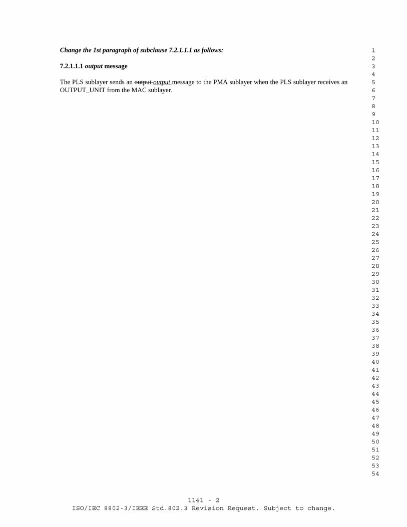
1141 - 2ISO/IEC 8802-3/IEEE Std.802.3 Revision Request. Subject to change.
1 2 3 4 5 6 7 8 9 10 11 12 13 14 15 16 17 18 19 20 21 22 23 24 25 26 27 28 29 30 31 32 33 34 35 36 37 38 39 40 41 42 43 44 45 46 47 48 49 50 51 52 53 54
Change the 1st paragraph of subclause 7.2.1.1.1 as follows:
7.2.1.1.1 output message
The PLS sublayer sends an output output message to the PMA sublayer when the PLS sublayer receives an OUTPUT_UNIT from the MAC sublayer.

1142 - 1ISO/IEC 8802-3/IEEE Std.802.3 Revision Request. Subject to change.
1 2 3 4 5 6 7 8 9 10 11 12 13 14 15 16 17 18 19 20 21 22 23 24 25 26 27 28 29 30 31 32 33 34 35 36 37 38 39 40 41 42 43 44 45 46 47 48 49 50 51 52 53 54
+----------------------------------------------------------------------+| 8802-3/802.3 REVISION REQUEST 1142 |+-----------------====================================-----------------+
DATE: 21st May, 2004NAME: Thomas Mathey
COMPANY/AFFILIATION: Independent
E-MAIL: [email protected]
REQUESTED REVISION:STANDARD: IEEE Std 802.3-2002CLAUSE NUMBER: 7.2.1.1.5
CLAUSE TITLE: mau_request message (optional)
PROPOSED REVISION TEXT:
For line"The PLS sublayer senses the mau_request message to the PMA sublayer", change text from "senses" to "sends".
RATIONALE FOR REVISION:
Mis-spelled word.
IMPACT ON EXISTING NETWORKS:
Editorial change only.
+----------------------------------------------------------------------+| Please attach supporting material, if any || Submit to:- Bob Grow, Chair IEEE 802.3 || E-Mail: [email protected] || || +------- For official 802.3 use -----------+ || | REV REQ NUMBER: 1142 | || | DATE RECEIVED: 21st May, 2004 | || | EDITORIAL/TECHNICAL | || | ACCEPTED/DENIED | || | BALLOT REQ'D YES/NO | || | COMMENTS: 05-Jul-04 Ver: D1.1 Status: B | |+-------------+------------------------------------------+-------------+| For information about this Revision Request see - ||http://www.ieee802.org/3/maint/requests/revision_history.html#REQ1142 |+----------------------------------------------------------------------+

1142 - 2ISO/IEC 8802-3/IEEE Std.802.3 Revision Request. Subject to change.
1 2 3 4 5 6 7 8 9 10 11 12 13 14 15 16 17 18 19 20 21 22 23 24 25 26 27 28 29 30 31 32 33 34 35 36 37 38 39 40 41 42 43 44 45 46 47 48 49 50 51 52 53 54
Change the 1st paragraph of subclause 7.2.1.1.5 as follows:
7.2.1.1.5 mau_request message (optional)
The PLS sublayer senses sends the mau_request message to the PMA sublayer if the PMA sublayer is send-ing the mau_not_available message and the MAC sublayer has sent the first OUTPUT_UNIT of a new transmission. The PLS sublayer continues to send the mau_request message to the MAU until the MAC sub-layer sends the DATA_COMPLETE request to the PLS sublayer across the MAC to PLS interface. See Fig-ures 7–3, 7–5, and 7–9 for details.

1143 - 1ISO/IEC 8802-3/IEEE Std.802.3 Revision Request. Subject to change.
1 2 3 4 5 6 7 8 9 10 11 12 13 14 15 16 17 18 19 20 21 22 23 24 25 26 27 28 29 30 31 32 33 34 35 36 37 38 39 40 41 42 43 44 45 46 47 48 49 50 51 52 53 54
+----------------------------------------------------------------------+| 8802-3/802.3 REVISION REQUEST 1143 |+-----------------====================================-----------------+
DATE: 21st May, 2004NAME: Thomas MatheyCOMPANY/AFFILIATION: IndependentE-MAIL: [email protected]
REQUESTED REVISION:STANDARD: IEEE Std 802.3-2002CLAUSE NUMBER: Figure 7-6CLAUSE TITLE: PLS Input and Data_Valid function
PROPOSED REVISION TEXT:
Change text from "SQE * input_idle" to "not SQE * input_idle". The not applies only to SQE.
For details see attached draft.
RATIONALE FOR REVISION:
Error when figure was converted from 1996 version.
For exit from state "BIT BUCKET" to state "INPUT IDLE", an inversion on signal SQE was dropped in edits.
IMPACT ON EXISTING NETWORKS:
Editorial change only.
+----------------------------------------------------------------------+| Please attach supporting material, if any || Submit to:- Bob Grow, Chair IEEE 802.3 || E-Mail: [email protected] || || +------- For official 802.3 use -----------+ || | REV REQ NUMBER: 1143 | || | DATE RECEIVED: 21st May, 2004 | || | EDITORIAL/TECHNICAL | || | ACCEPTED/DENIED | || | BALLOT REQ'D YES/NO | || | COMMENTS: 05-Jul-04 Ver: D1.1 Status: B | |+-------------+------------------------------------------+-------------+| For information about this Revision Request see - ||http://www.ieee802.org/3/maint/requests/revision_history.html#REQ1143 |+----------------------------------------------------------------------+

1143 - 2ISO/IEC 8802-3/IEEE Std.802.3 Revision Request. Subject to change.
1 2 3 4 5 6 7 8 9 10 11 12 13 14 15 16 17 18 19 20 21 22 23 24 25 26 27 28 29 30 31 32 33 34 35 36 37 38 39 40 41 42 43 44 45 46 47 48 49 50 51 52 53 54
Replace Figure 7-6 with the following:
RESET
DATA_VALID_STATUS =DATA_NOT_VALID
BIT BUCKET
INPUT IDLE
DATA_VALID_STATUS =DATA_NOT_VALID
DISCARD TRASH
DATA_VALID_STATUS =DATA_NOT_VALID
[Discard the first 15 bits received]
INITIALIZE
[N = 1]
pls_reset
INPUT HOLD
INPUT DATA
Input-Unit (N)
INCREMENT
[N = N + 1]
pls_start
SQE * input_idle
CARRIER_ON
CARRIER_OFF
Input
UCT
UCT
Input (bit N)
Input (bit N+1)
pls_reset
Figure 7–6—PLS Input and Data_Valid function

1144 - 1ISO/IEC 8802-3/IEEE Std.802.3 Revision Request. Subject to change.
1 2 3 4 5 6 7 8 9 10 11 12 13 14 15 16 17 18 19 20 21 22 23 24 25 26 27 28 29 30 31 32 33 34 35 36 37 38 39 40 41 42 43 44 45 46 47 48 49 50 51 52 53 54
+----------------------------------------------------------------------+| 8802-3/802.3 REVISION REQUEST 1144 |+-----------------====================================-----------------+
DATE: 21st May, 2004NAME: Thomas MatheyCOMPANY/AFFILIATION: IndependentE-MAIL: [email protected]
REQUESTED REVISION:STANDARD: IEEE Std 802.3-2002CLAUSE NUMBER: 14.2.1.5CLAUSE TITLE: signal_quality_error Message (SQE) Test function
PROPOSED REVISION TEXT:
Change text from"shall be between 0. µs and 1.6 µs."to "shall be between 0.6 µs and 1.6 µs."by adding text "6" for 0.6 µs.
For details see attached draft.
RATIONALE FOR REVISION:
Text is missing a number.
IMPACT ON EXISTING NETWORKS:
Editorial change only.
+----------------------------------------------------------------------+| Please attach supporting material, if any || Submit to:- Bob Grow, Chair IEEE 802.3 || E-Mail: [email protected] || || +------- For official 802.3 use -----------+ || | REV REQ NUMBER: 1144 | || | DATE RECEIVED: 21st May, 2004 | || | EDITORIAL/TECHNICAL | || | ACCEPTED/DENIED | || | BALLOT REQ'D YES/NO | || | COMMENTS: 05-Jul-04 Ver: D1.1 Status: B | |+-------------+------------------------------------------+-------------+| For information about this Revision Request see - ||http://www.ieee802.org/3/maint/requests/revision_history.html#REQ1144 |+----------------------------------------------------------------------+

1144 - 2ISO/IEC 8802-3/IEEE Std.802.3 Revision Request. Subject to change.
1 2 3 4 5 6 7 8 9 10 11 12 13 14 15 16 17 18 19 20 21 22 23 24 25 26 27 28 29 30 31 32 33 34 35 36 37 38 39 40 41 42 43 44 45 46 47 48 49 50 51 52 53 54
14.2.1.5 signal_quality_error Message (SQE) Test function requirements
Change the 1st paragraph of subclause 14.2.1.5 as follows:
The SQE Test function shall be performed by MAUs that are connected to DTEs in half duplex mode, and shall not be performed by MAUs that are connected to repeaters. When the SQE test is performed, the MAU shall send CS0 on the CI circuit for a time “SQE_test” beginning a time “SQE_test_wait” after the last posi-tive transition of a packet on the DO circuit. The value of “SQE_test” shall be 10 BT ± 5 BT and the value of “SQE_test_wait” shall be between 0.6 µs and 1.6 µs. This function should use as much of the normal colli-sion detection and signaling circuitry as possible without introducing extraneous signals on the TD circuit or the DI circuit.

1145 - 1ISO/IEC 8802-3/IEEE Std.802.3 Revision Request. Subject to change.
1 2 3 4 5 6 7 8 9 10 11 12 13 14 15 16 17 18 19 20 21 22 23 24 25 26 27 28 29 30 31 32 33 34 35 36 37 38 39 40 41 42 43 44 45 46 47 48 49 50 51 52 53 54
+----------------------------------------------------------------------+| 8802-3/802.3 REVISION REQUEST 1145 |+-----------------====================================-----------------+
DATE: 21st May, 2004NAME: Thomas MatheyCOMPANY/AFFILIATION: IndependentE-MAIL: [email protected]
REQUESTED REVISION:STANDARD: IEEE Std 802.3-2002CLAUSE NUMBER: 14.2.3.2CLAUSE TITLE: State diagram timers
PROPOSED REVISION TEXT:
Change text from "Link Fail" to "Link Test Fail" by adding text "Test"
RATIONALE FOR REVISION:
Text for"link_test_max_timer. Timer for maximum time input activity can be missing before Link Fail state is exited (14.2.1.7)." does not match name of state in state diagram.
State name is "Link Test Fail".
For details see attached draft.
IMPACT ON EXISTING NETWORKS:
Editorial change only.
+----------------------------------------------------------------------+| Please attach supporting material, if any || Submit to:- Bob Grow, Chair IEEE 802.3 || E-Mail: [email protected] || || +------- For official 802.3 use -----------+ || | REV REQ NUMBER: 1145 | || | DATE RECEIVED: 21st May, 2004 | || | EDITORIAL/TECHNICAL | || | ACCEPTED/DENIED | || | BALLOT REQ'D YES/NO | || | COMMENTS: 05-Jul-04 Ver: D1.1 Status: B | |+-------------+------------------------------------------+-------------+| For information about this Revision Request see - ||http://www.ieee802.org/3/maint/requests/revision_history.html#REQ1145 |+----------------------------------------------------------------------+

1145 - 2ISO/IEC 8802-3/IEEE Std.802.3 Revision Request. Subject to change.
1 2 3 4 5 6 7 8 9 10 11 12 13 14 15 16 17 18 19 20 21 22 23 24 25 26 27 28 29 30 31 32 33 34 35 36 37 38 39 40 41 42 43 44 45 46 47 48 49 50 51 52 53 54
Change timer ‘link_test_max_timer’ of subclause 14.2.3.2 as follows:
link_test_max_timer. Timer for maximum time input activity can be missing before Link Test Fail state is exited (14.2.1.7).

1146 - 1ISO/IEC 8802-3/IEEE Std.802.3 Revision Request. Subject to change.
1 2 3 4 5 6 7 8 9 10 11 12 13 14 15 16 17 18 19 20 21 22 23 24 25 26 27 28 29 30 31 32 33 34 35 36 37 38 39 40 41 42 43 44 45 46 47 48 49 50 51 52 53 54
+----------------------------------------------------------------------+| 8802-3/802.3 REVISION REQUEST 1146 |+-----------------====================================-----------------+
DATE: 21st May, 2004NAME: Thomas Mathey
COMPANY/AFFILIATION: Independent
E-MAIL: [email protected]
REQUESTED REVISION:STANDARD: IEEE Std 802.3-2002CLAUSE NUMBER: Figure 14-3
CLAUSE TITLE: MAU state diagrams
PROPOSED REVISION TEXT:
For both 14-3 a) and 14-3 b), change text from "RD = active" to "RD = active * rcv = enable" by adding text "rcv = enable".
RATIONALE FOR REVISION:
In Figure 14-6 - Link Integrity Test function state diagram, the variables xmit, rcv, and lpbk are enabled and disabled. However, there is no use made of variable "rcv".
This variable needs to be used in Figure 14-3 a) and b) to qualify transition from state "IDLE" to state "INPUT" for receive frames such that frames on the receive path are blocked when the link is disabled. Note that if link pulses are initially absent, the first incoming frame is dropped, and the link is then set to enabled.
All of the UNH-IOL tests and the 10BASE-T conformance document require that the link be placed in the link pass state (which assumes that variable rcv = enable) before the MAU passes frames to the MAC.
IMPACT ON EXISTING NETWORKS:
Editorial change only.
+----------------------------------------------------------------------+| Please attach supporting material, if any || Submit to:- Bob Grow, Chair IEEE 802.3 || E-Mail: [email protected] || || +------- For official 802.3 use -----------+ || | REV REQ NUMBER: 1146 | || | DATE RECEIVED: 21st May, 2004 | || | EDITORIAL/TECHNICAL | || | ACCEPTED/DENIED | || | BALLOT REQ'D YES/NO | || | COMMENTS: 25-May-04 Ver: D1.0 Status: B | |+-------------+------------------------------------------+-------------+| For information about this Revision Request see - ||http://www.ieee802.org/3/maint/requests/revision_history.html#REQ1146 |+----------------------------------------------------------------------+

1147 - 1ISO/IEC 8802-3/IEEE Std.802.3 Revision Request. Subject to change.
1 2 3 4 5 6 7 8 9 10 11 12 13 14 15 16 17 18 19 20 21 22 23 24 25 26 27 28 29 30 31 32 33 34 35 36 37 38 39 40 41 42 43 44 45 46 47 48 49 50 51 52 53 54
+----------------------------------------------------------------------+| 8802-3/802.3 REVISION REQUEST 1147 |+-----------------====================================-----------------+
DATE: 21st May, 2004NAME: Thomas Mathey
COMPANY/AFFILIATION: Independent
E-MAIL: [email protected]
REQUESTED REVISION:STANDARD: IEEE Std 802.3-2002CLAUSE NUMBER: Table 14-2
CLAUSE TITLE: Maximum timing parameters
PROPOSED REVISION TEXT:
Change text from "RD_input" to "RD_input" by adding italic attribute to text "RD_input".
Change text from "output" to "output" by adding italic attribute to text "output".
Change text from "signal_quality_error" to "signal_quality_error" by adding italic attribute to text "signal_quality_error".
For details see attached draft.
RATIONALE FOR REVISION:
Text should be in italics.
IMPACT ON EXISTING NETWORKS:
Editorial change only.
+----------------------------------------------------------------------+| Please attach supporting material, if any || Submit to:- Bob Grow, Chair IEEE 802.3 || E-Mail: [email protected] || || +------- For official 802.3 use -----------+ || | REV REQ NUMBER: 1147 | || | DATE RECEIVED: 21st May, 2004 | || | EDITORIAL/TECHNICAL | || | ACCEPTED/DENIED | || | BALLOT REQ'D YES/NO | || | COMMENTS: 05-Jul-04 Ver: D1.1 Status: B | |+-------------+------------------------------------------+-------------+| For information about this Revision Request see - ||http://www.ieee802.org/3/maint/requests/revision_history.html#REQ1147 |+----------------------------------------------------------------------+

1147 - 2ISO/IEC 8802-3/IEEE Std.802.3 Revision Request. Subject to change.
1 2 3 4 5 6 7 8 9 10 11 12 13 14 15 16 17 18 19 20 21 22 23 24 25 26 27 28 29 30 31 32 33 34 35 36 37 38 39 40 41 42 43 44 45 46 47 48 49 50 51 52 53 54
Replace Table 14-2 with the following (Summary of changes - in M3 change ‘RD_input’ to read ‘RD_input’, ‘output’ to read ‘output’ and ‘signal_quality_error’ to read ‘signal_quality_error’, in M8 change ‘signal_quality_error’ to read ‘signal_quality_error’):
Table 14–2—Maximum timing parameters
Symbol Function Bit Lossa
aAll time in BT.
Invalid Bitsb
bFor an explanation of the meaning of variability, see 14.2.1.1 and 14.2.1.2.
Steady-State Propagation
Delayb
Start-up Delayb Specifiedin
Maximum Variability
M1 RD_input to input on DI
5.0 1.0 2.0 8.0 2.0 14.2.1.2
M2 output on DO to TD_output
2.0 1.0 2.0 5.0 2.0 14.2.1.1
M3 RD_input * output to signal_quality_error
— — — 9.0 — 14.2.1.4
M4 RD_idle + output_ idle (end of collision)to mau_available
— — — 9.0 — 14.2.1.4
M5 RD_input * output to input on DI from cir-cuit RD
— — — 9.0 — 14.2.1.4
M6 RD_idle * output to input on DI from cir-cuit DO
— — — 9.0 — 14.2.1.4
M7 output_idle on DO to signal_quality_error
— — — 6 < × < 16 — 14.2.1.5
M8 signal_quality_errorduration for SQE test
— — — 5 < × < 15 — 14.2.1.5
M9 output on DO to input on DI
5.0 1.0 1.0 7.0 — 14.2.1.3
T1 twisted-pair propagation
0 0 10.00 10.00 — 14.4.2.4
A1 AUI cable propagation(50 m)
0 0 2.57 2.57 — 7.4.3.7

1148 - 1ISO/IEC 8802-3/IEEE Std.802.3 Revision Request. Subject to change.
1 2 3 4 5 6 7 8 9 10 11 12 13 14 15 16 17 18 19 20 21 22 23 24 25 26 27 28 29 30 31 32 33 34 35 36 37 38 39 40 41 42 43 44 45 46 47 48 49 50 51 52 53 54
+----------------------------------------------------------------------+| 8802-3/802.3 REVISION REQUEST 1148 |+-----------------====================================-----------------+
DATE: 21th May, 2004NAME: Thomas MatheyCOMPANY/AFFILIATION: IndependentE-MAIL: [email protected]
REQUESTED REVISION:STANDARD: IEEE Std 802.3-2002CLAUSE NUMBER: Figure 27-1CLAUSE TITLE: 100BASE-T repeater set
PROPOSED REVISION TEXT:
Remove text
LANCSMA/CDLAYERS
See attached draft.
RATIONALE FOR REVISION:
Figure has text hanging out in midspace with no attachment to a layer.Figure in Clause 41 has more detail and text has a reference point.
IMPACT ON EXISTING NETWORKS:
Editorial change only.
+----------------------------------------------------------------------+| Please attach supporting material, if any || Submit to:- Bob Grow, Chair IEEE 802.3 || E-Mail: [email protected] || || +------- For official 802.3 use -----------+ || | REV REQ NUMBER: 1148 | || | DATE RECEIVED: 21th May, 2004 | || | EDITORIAL/TECHNICAL | || | ACCEPTED/DENIED | || | BALLOT REQ'D YES/NO | || | COMMENTS: 05-Jul-04 Ver: D1.1 Status: R | |+-------------+------------------------------------------+-------------+| For information about this Revision Request see - ||http://www.ieee802.org/3/maint/requests/revision_history.html#REQ1148 |+----------------------------------------------------------------------+

1148 - 2ISO/IEC 8802-3/IEEE Std.802.3 Revision Request. Subject to change.
1 2 3 4 5 6 7 8 9 10 11 12 13 14 15 16 17 18 19 20 21 22 23 24 25 26 27 28 29 30 31 32 33 34 35 36 37 38 39 40 41 42 43 44 45 46 47 48 49 50 51 52 53 54
Change Figure 27-1 as follows:
PRESENTATION
APPLICATION
SESSION
TRANSPORT
NETWORK
DATA LINK
PHYSICAL
OSI REFERENCE
MODELLAYERS
LANCSMA/CDLAYERS
* PMD
MDI = MEDIUM DEPENDENT INTERFACEMII = MEDIA INDEPENDENT INTERFACE
PCS = PHYSICAL CODING SUBLAYER
Use of MII between PCS and baseband repeater unit is optional.
PMA = PHYSICAL MEDIUM ATTACHMENT
PHY
PHY = PHYSICAL LAYER DEVICE
MDI
PMA
PMD = PHYSICAL MEDIUM DEPENDENT
100 Mb/s link segment
PCS100BASE-T
Repeater SetBaseband
* PMD is specified for 100BASE-TX and -FX only; 100BASE-T4 does not use this layer.
100BASE-T BasebandRepeater
Unit
* PMDPHY
MDI
PMA
100 Mb/s link segment
PCS
MEDIUM MEDIUM
**AUTONEG **AUTONEG
** AUTONEG is optional.
Figure 27–1—100BASE-T repeater set relationship to the ISO/IEC OSI reference model

1149 - 1ISO/IEC 8802-3/IEEE Std.802.3 Revision Request. Subject to change.
1 2 3 4 5 6 7 8 9 10 11 12 13 14 15 16 17 18 19 20 21 22 23 24 25 26 27 28 29 30 31 32 33 34 35 36 37 38 39 40 41 42 43 44 45 46 47 48 49 50 51 52 53 54
+----------------------------------------------------------------------+| 8802-3/802.3 REVISION REQUEST 1149 |+-----------------====================================-----------------+
DATE: 25th May, 2004NAME: Jeremy KentCOMPANY/AFFILIATION: UNH InterOperability LabE-MAIL: [email protected]
REQUESTED REVISION:STANDARD: IEEE Std. 802.3-2002CLAUSE NUMBER: 40C.1, 40C.2.1, and Figure 40C-2CLAUSE TITLE: Auto-Negotiation Transmit state machine add-on
for 1000BASE-T
PROPOSED REVISION TEXT:
See attached draft.
RATIONALE FOR REVISION:
This change was included in the approved draft of IEEE Std 802.3ag-2002 and should have been published as part of IEEE Std 802.3-2002 but was not.
IMPACT ON EXISTING NETWORKS:
None. This change is to an informative Annex and therefore will have no effect on equipment compliance. Equipment manufactured using this change will interoperate with existing equipment.
+----------------------------------------------------------------------+| Please attach supporting material, if any || Submit to:- Bob Grow, Chair IEEE 802.3 || E-Mail: [email protected] || || +------- For official 802.3 use -----------+ || | REV REQ NUMBER: 1149 | || | DATE RECEIVED: 25th May, 2004 | || | EDITORIAL/TECHNICAL | || | ACCEPTED/DENIED | || | BALLOT REQ'D YES/NO | || | COMMENTS: 25-May-04 Ver: D1.0 Status: E | |+-------------+------------------------------------------+-------------+| For information about this Revision Request see - ||http://www.ieee802.org/3/maint/requests/revision_history.html#REQ1149 |+----------------------------------------------------------------------+

1149 - 2ISO/IEC 8802-3/IEEE Std.802.3 Revision Request. Subject to change.
1 2 3 4 5 6 7 8 9 10 11 12 13 14 15 16 17 18 19 20 21 22 23 24 25 26 27 28 29 30 31 32 33 34 35 36 37 38 39 40 41 42 43 44 45 46 47 48 49 50 51 52 53 54
40C.1 State variables
Delete the following variable from 40C.1:
1000T_capable This variable is used merely to show the local device is 1000Base-T capable. It is shown to illustrate the path that a non-1000Base-T device would take within the auto negotiation mechanism.
Insert the following variable in 40C.1 (this should be inserted in alphabetical order):
desire_1000T_adv The local device desires a 1000BASE-T link. Values: true; bits 9.8 or 9.9 do not contain a logic zero.
false; bits 9.8 and 9.9 both contain a logic zero.
Figure 40C–2—Auto-Negotiation Transmit state diagram add-on for 1000BASE-T
Change note 3 of Figure 40C-2:
3—(Flp_Link_Good_Check) This is shown for illustration only. This state is from the Auto-Negotiation arbitration state diagram and indicates the conclusion of pages being sent. (The transition desire_1000T_adv1000T_capable = false is to show sequence for non 1000BASE-T implementations.)

1150 - 1ISO/IEC 8802-3/IEEE Std.802.3 Revision Request. Subject to change.
1 2 3 4 5 6 7 8 9 10 11 12 13 14 15 16 17 18 19 20 21 22 23 24 25 26 27 28 29 30 31 32 33 34 35 36 37 38 39 40 41 42 43 44 45 46 47 48 49 50 51 52 53 54
+----------------------------------------------------------------------+| 8802-3/802.3 REVISION REQUEST 1150 |+-----------------====================================-----------------+
DATE: 25th May, 2004NAME: Jeremy KentCOMPANY/AFFILIATION: UNH InterOperability LabE-MAIL: [email protected]
REQUESTED REVISION:STANDARD: IEEE Std. 802.3-2002CLAUSE NUMBER: 40C.2.1 and Figure 40C-2CLAUSE TITLE: Auto-Negotiation Transmit state machine add-on
for 1000BASE-T
PROPOSED REVISION TEXT:
See attached draft.
In Figure 40C-2, in the transition conditions between WAIT3 and Flp_Link_Good_Check, change the transition condition from rx_link_code_word[NP]=1 to rx_link_code_word[NP]=0.
Furthermore, rx_link_code_word[NP]=1 should be added to the transition conditions between WAIT3 and 1000T_NULL_TX.
RATIONALE FOR REVISION:
These additions were originally in request 1045 however the diagram balloted did not implement these correctly.
IMPACT ON EXISTING NETWORKS:
None. This change is to an informative Annex and therefore will have no effect on equipment compliance. Equipment manufactured using this change will interoperate with existing equipment.
+----------------------------------------------------------------------+| Please attach supporting material, if any || Submit to:- Bob Grow, Chair IEEE 802.3 || E-Mail: [email protected] || || +------- For official 802.3 use -----------+ || | REV REQ NUMBER: 1150 | || | DATE RECEIVED: 25th May, 2004 | || | EDITORIAL/TECHNICAL | || | ACCEPTED/DENIED | || | BALLOT REQ'D YES/NO | || | COMMENTS: 25-May-04 Ver: D1.0 Status: B | |+-------------+------------------------------------------+-------------+| For information about this Revision Request see - ||http://www.ieee802.org/3/maint/requests/revision_history.html#REQ1150 |+----------------------------------------------------------------------+

1150 - 2ISO/IEC 8802-3/IEEE Std.802.3 Revision Request. Subject to change.
1 2 3 4 5 6 7 8 9 10 11 12 13 14 15 16 17 18 19 20 21 22 23 24 25 26 27 28 29 30 31 32 33 34 35 36 37 38 39 40 41 42 43 44 45 46 47 48 49 50 51 52 53 54
Replace Figure 40C-2 with the following (Changed highlighted):
Figure 40C–2—Auto-Negotiation Transmit state diagram add-on for 1000BASE-T
1000T_MP_TX
Base_Page_TX
1000T_UP1_TX
1000T_UP2_TX
1000T_NULL_TX
Flp_Link_Good_Check(*3)
Software_NP_TX(*1)
Software_NULL_TX(*2)
mr_np_tx[11:1] ⇐ “8”mr_np_tx[NP] ⇐ 1mr_np_tx[MP] ⇐ 1
mr_np_tx[11:1] ⇐ mr_1000t_adv_ability[11:1]mr_np_tx[NP] ⇐ 1mr_np_tx[MP] ⇐ 0
mr_np_tx[11:1] ⇐ “reg_random”mr_np_tx[NP] ⇐ mr_bp[NP]mr_np_tx[MP] ⇐ 0
mr_np_tx[11:2] ⇐ “0”
mr_bp[NP] = 1 *
mr_np_tx_reg[NP] = 1 *
rx_link_code_word[NP] = 0 *
rx_link_code_word[NP] = 1 * rx_link_code_word[NP] = 0 *
Reset_1000T
power_on = true +mr_main_reset = true +mr_restart_negotiation = true +mr_autoneg_enable = false +
ATMP_CNT ⇐ 0
ATMP_CNT ⇐
mr_autoneg_complete = true
mr_adv_ability[NP] ⇐ desire_1000T_adv + mr_bp[NP]mr_adv_ability[15:1] ⇐ mr_bp[15:1]
transmit_disable = true
mr_page_rx = true * ack_finished = true
mr_page_rx = false
mr_page_rx = true * ack_finished = true
mr_page_rx = false
mr_page_rx = false
mr_page_rx = falsemr_page_rx = true *
mr_page_rx = true *
mr_page_rx = true *
mr_page_rx = true * mr_page_rx = true *
next_page_loaded = true *
next_page_loaded = true *
mr_next_page_loaded ⇐ next_page_loadedmr_np_tx[11:1] ⇐ mr_np_tx_reg[11:1]
WAIT2
WAIT3
mr_np_tx_reg[NP] = 0 * mr_page_rx = true * next_page_loaded = true *
mr_page_rx = true * mr_lp_np_able = true *
UCT
ATMP_CNT + 1
desire_1000T_adv = false * mr_bp[NP] = 1
ack_finished = true
ack_finished = true
ack_finished = true
ack_finished = true
mr_np_tx[1] ⇐ “1”mr_np_tx[NP] ⇐ 0mr_no_tx[MP] ⇐ 1mr_next_page_loaded ⇐ next_page_loaded
mr_np_tx[11:2] ⇐ “0”mr_np_tx[1] ⇐ “1”mr_np_tx[NP] ⇐ 0mr_no_tx[MP] ⇐ 1mr_next_page_loaded ⇐ true
mr_page_rx = true *
desire_1000T_adv = true *mr_lp_np_able = true *
ack_finished = true
(mr_lp_np_able = false +(desire_1000T_adv = false *
mr_bp[NP] = 0)) *
WAIT1
rx_link_code_word[NP] = 0 *mr_page_rx = true *ack_finished = true
rx_link_code_word[NP] = 1 *
WAIT4
mr_page_rx = true *ack_finished = true
ack_finished = true
ack_finished = true
next_page_loaded = true *
mr_page_rx = true *ack_finished = true
rx_link_code_word[NP] = 0 *
IF(next_page_loaded = true + mr_bp[NP] = 0)THEN mr_next_page_loaded ⇐ true
IF(next_page_loaded = true + mr_bp[NP] = 0)THEN mr_next_page_loaded ⇐ true
IF(next_page_loaded = true + mr_bp[NP] = 0)THEN mr_next_page_loaded ⇐ true
mr_page_rx = true
mr_np_tx_reg[NP] = 0 * mr_page_rx = true * ack_finished = true
rx_link_code_word[NP] =0 *
mr_bp[NP] = 0 *
rx_link_code_word[NP] = 1 * mr_bp[NP] = 0 * mr_page_rx = true * ack_finished = true

1151 - 1ISO/IEC 8802-3/IEEE Std.802.3 Revision Request. Subject to change.
1 2 3 4 5 6 7 8 9 10 11 12 13 14 15 16 17 18 19 20 21 22 23 24 25 26 27 28 29 30 31 32 33 34 35 36 37 38 39 40 41 42 43 44 45 46 47 48 49 50 51 52 53 54
+----------------------------------------------------------------------+| 8802-3/802.3 REVISION REQUEST 1151 |+-----------------====================================-----------------+
DATE: 1st Jun, 2004NAME: Dan DoveCOMPANY/AFFILIATION: hp ProCurveE-MAIL: [email protected]
REQUESTED REVISION:STANDARD: IEEE Std 802.3ak-2004CLAUSE NUMBER: 54.6.3.2CLAUSE TITLE: Test Fixture Impedance
PROPOSED REVISION TEXT:
Change Paragraph:
From:
"The nominal differential impedance of the transmit test fixture depicted in Figure 54-3 shall be 100 Ohms with a return loss greater than 20 dB from 100 MHz to 2000 MHz."
To:
"The differential load impedance applied to the transmitter output by the test fixture depicted in Figure 54-3 shall have a return loss greater than 20 dB from 100 MHz to 2000 MHz. The reference impedance for differential return loss measurements shall be 100 Ohms."
RATIONALE FOR REVISION:
The impedance specification is this clause is ambiguous. The test fixture is shown in Figure 54-3 to have two ports, one that connects to the transmitter output and one that connnects to the "Post Processing" block. The clause does not specify whether the impedance specification applies to the port that connects to the transmitter output, the "Post Processing" block or both.
In addition, the return loss specification applies to the actual impedance applied to the transmitter output by the test fixture, not to the nominal value of the impedance.
IMPACT ON EXISTING NETWORKS:
None. It only clarifies the original functional requirement.

1151 - 2ISO/IEC 8802-3/IEEE Std.802.3 Revision Request. Subject to change.
1 2 3 4 5 6 7 8 9 10 11 12 13 14 15 16 17 18 19 20 21 22 23 24 25 26 27 28 29 30 31 32 33 34 35 36 37 38 39 40 41 42 43 44 45 46 47 48 49 50 51 52 53 54
+----------------------------------------------------------------------+| Please attach supporting material, if any || Submit to:- Bob Grow, Chair IEEE 802.3 || E-Mail: [email protected] || || +------- For official 802.3 use -----------+ || | REV REQ NUMBER: 1151 | || | DATE RECEIVED: 1st Jun, 2004 | || | EDITORIAL/TECHNICAL | || | ACCEPTED/DENIED | || | BALLOT REQ'D YES/NO | || | COMMENTS: 01-Jun-04 Ver: D1.0 Status: R | |+-------------+------------------------------------------+-------------+| For information about this Revision Request see - ||http://www.ieee802.org/3/maint/requests/revision_history.html#REQ1151 |+----------------------------------------------------------------------+

1152 - 1ISO/IEC 8802-3/IEEE Std.802.3 Revision Request. Subject to change.
1 2 3 4 5 6 7 8 9 10 11 12 13 14 15 16 17 18 19 20 21 22 23 24 25 26 27 28 29 30 31 32 33 34 35 36 37 38 39 40 41 42 43 44 45 46 47 48 49 50 51 52 53 54
+----------------------------------------------------------------------+| 8802-3/802.3 REVISION REQUEST 1152 |+-----------------====================================-----------------+
DATE: 8th Jul, 2004NAME: Glen KramerCOMPANY/AFFILIATION: Teknovus, Inc.E-MAIL: [email protected]
REQUESTED REVISION:STANDARD: IEEE Std 802.3ah-2004CLAUSE NUMBER: 64.3.3.2CLAUSE TITLE: Variables
PROPOSED REVISION TEXT:
The value of syncTime includes gain adjustment interval (Treceiver_settling), clock synchronization interval (Tcdr), and codegroup alignment interval (Tcode_group_align), as specified in 60.7.13.2.
For details see attached draft.
RATIONALE FOR REVISION:
The state machines in Figures 64-28 and 64-29 account for laser_on time (Ton) in addition to syncTime. If Ton is also included in syncTime, it will be accounted for twice, thus potentially breaking the scheduling.
IMPACT ON EXISTING NETWORKS:
None. All existing implementations do not include laser_on time in syncTime.
+----------------------------------------------------------------------+| Please attach supporting material, if any || Submit to:- Bob Grow, Chair IEEE 802.3 || E-Mail: [email protected] || || +------- For official 802.3 use -----------+ || | REV REQ NUMBER: 1152 | || | DATE RECEIVED: 8th Jul, 2004 | || | EDITORIAL/TECHNICAL | || | ACCEPTED/DENIED | || | BALLOT REQ'D YES/NO | || | COMMENTS: 08-Jul-04 Ver: D1.0 Status: R | |+-------------+------------------------------------------+-------------+| For information about this Revision Request see - ||http://www.ieee802.org/3/maint/requests/revision_history.html#REQ1152 |+----------------------------------------------------------------------+

1152 - 2ISO/IEC 8802-3/IEEE Std.802.3 Revision Request. Subject to change.
1 2 3 4 5 6 7 8 9 10 11 12 13 14 15 16 17 18 19 20 21 22 23 24 25 26 27 28 29 30 31 32 33 34 35 36 37 38 39 40 41 42 43 44 45 46 47 48 49 50 51 52 53 54
64.3.3.2 Variables
Change the variable syncTime as follows:
syncTime This variable holds the time required to stabilize the receiver at the OLT. It counts time_quanta units from the point where transmission output is stable to the point where synchronization has been achieved. The value of syncTime includes laser on time (Ton),gain adjustment interval (Treceiver_settling), clock synchronization interval (Tcdr), and codegroup alignment interval (Tcode_group_align), as specified in 60.7.13.2. The OLT conveys the value of syncTime to ONUs in Discovery GATE and REGISTER messages. During the synchronization time only IDLE patterns can be transmitted by an ONU. TYPE: 16 bit unsigned

1153 - 1ISO/IEC 8802-3/IEEE Std.802.3 Revision Request. Subject to change.
1 2 3 4 5 6 7 8 9 10 11 12 13 14 15 16 17 18 19 20 21 22 23 24 25 26 27 28 29 30 31 32 33 34 35 36 37 38 39 40 41 42 43 44 45 46 47 48 49 50 51 52 53 54
+----------------------------------------------------------------------+| 8802-3/802.3 REVISION REQUEST 1153 |+-----------------====================================-----------------+
DATE: 8th Jul, 2004NAME: Glen KramerCOMPANY/AFFILIATION: Teknovus, Inc.E-MAIL: [email protected]
REQUESTED REVISION:STANDARD: IEEE Std 802.3ah-2004CLAUSE NUMBER: 64.3.3.5CLAUSE TITLE: Messages
PROPOSED REVISION TEXT:
The description of DA parameter of MA_CONTROL.request service primitive for REGISTER MPCPDU should be channged to:
DA: unicast MAC address.
For details see attached draft.
RATIONALE FOR REVISION:
According to MPCP discovery protocol, the REGISTER MPCPDU should be send to an individual ONU, but the logical point-to-point channel to this ONU is not established yet. Therefore, the MPCPDU is sent on broadcast channel with unicast MAC address.
IMPACT ON EXISTING NETWORKS:
None. All existing implementations transmit REGISTER MPCPDU with unicast MAC address.
+----------------------------------------------------------------------+| Please attach supporting material, if any || Submit to:- Bob Grow, Chair IEEE 802.3 || E-Mail: [email protected] || || +------- For official 802.3 use -----------+ || | REV REQ NUMBER: 1153 | || | DATE RECEIVED: 8th Jul, 2004 | || | EDITORIAL/TECHNICAL | || | ACCEPTED/DENIED | || | BALLOT REQ'D YES/NO | || | COMMENTS: 08-Jul-04 Ver: D1.0 Status: R | |+-------------+------------------------------------------+-------------+| For information about this Revision Request see - ||http://www.ieee802.org/3/maint/requests/revision_history.html#REQ1153 |+----------------------------------------------------------------------+

1153 - 2ISO/IEC 8802-3/IEEE Std.802.3 Revision Request. Subject to change.
1 2 3 4 5 6 7 8 9 10 11 12 13 14 15 16 17 18 19 20 21 22 23 24 25 26 27 28 29 30 31 32 33 34 35 36 37 38 39 40 41 42 43 44 45 46 47 48 49 50 51 52 53 54
64.3.3.5 Messages
Change the MA_CONTROL.request service primitive as follows:
MA_CONTROL.request(DA, GATE, discovery, start, length, discovery_length, sync_time) The service primitive used by the MAC Control client at the OLT to initiate the Discovery Process. This primitive takes the following parameters:
DA: multicast or unicast MAC address.GATE: opcode for GATE MPCPDU as defined in Table 31A–1.discovery: flag specifying that the given GATE message is to be used
for discovery only.start: start time of the discovery window.length: length of the grant given for discovery.discovery_length: length of the discovery window process.sync_time: the time interval required to stabilize the receiver at the
OLT.

1154 - 1ISO/IEC 8802-3/IEEE Std.802.3 Revision Request. Subject to change.
1 2 3 4 5 6 7 8 9 10 11 12 13 14 15 16 17 18 19 20 21 22 23 24 25 26 27 28 29 30 31 32 33 34 35 36 37 38 39 40 41 42 43 44 45 46 47 48 49 50 51 52 53 54
+----------------------------------------------------------------------+| 8802-3/802.3 REVISION REQUEST 1154 |+-----------------====================================-----------------+
DATE: 8th Jul, 2004NAME: Glen KramerCOMPANY/AFFILIATION: Teknovus, Inc.E-MAIL: [email protected]
REQUESTED REVISION:STANDARD: IEEE Std 802.3ah-2004CLAUSE NUMBER: 64.2.2.1CLAUSE TITLE: Constants
PROPOSED REVISION TEXT:
value of guardThresholdOLT should be 12 TQvalue of guardThresholdONU should be 8 TQ
For details see attached draft.
RATIONALE FOR REVISION:
The values of guardThresholdOLT and guardThresholdONU are mixed. This seems like a mistake made while preparing D3.2.
Refer to comment 64001 in http://www.ieee802.org/3/efm/public/comments/d3_1/D3_1_final_report.pdf
IMPACT ON EXISTING NETWORKS:
None.
+----------------------------------------------------------------------+| Please attach supporting material, if any || Submit to:- Bob Grow, Chair IEEE 802.3 || E-Mail: [email protected] || || +------- For official 802.3 use -----------+ || | REV REQ NUMBER: 1154 | || | DATE RECEIVED: 8th Jul, 2004 | || | EDITORIAL/TECHNICAL | || | ACCEPTED/DENIED | || | BALLOT REQ'D YES/NO | || | COMMENTS: 08-Jul-04 Ver: D1.0 Status: R | |+-------------+------------------------------------------+-------------+| For information about this Revision Request see - ||http://www.ieee802.org/3/maint/requests/revision_history.html#REQ1154 |+----------------------------------------------------------------------+

1154 - 2ISO/IEC 8802-3/IEEE Std.802.3 Revision Request. Subject to change.
1 2 3 4 5 6 7 8 9 10 11 12 13 14 15 16 17 18 19 20 21 22 23 24 25 26 27 28 29 30 31 32 33 34 35 36 37 38 39 40 41 42 43 44 45 46 47 48 49 50 51 52 53 54
64.2.2.1 Constants
Change the guardThresholdOLT and guardThresholdONU constants as follows:
guardThresholdOLT This constant holds the maximal amount of drift allowed for a timestamp received at the OLT. This value is measured in units of time_quantum (16 bit times). TYPE: integer VALUE: 812
guardThresholdONU This constant holds the maximal amount of drift allowed for a timestamp received at the ONU. This value is measured in units of time_quantum (16 bit times) TYPE: integer VALUE: 128

1155 - 1ISO/IEC 8802-3/IEEE Std.802.3 Revision Request. Subject to change.
1 2 3 4 5 6 7 8 9 10 11 12 13 14 15 16 17 18 19 20 21 22 23 24 25 26 27 28 29 30 31 32 33 34 35 36 37 38 39 40 41 42 43 44 45 46 47 48 49 50 51 52 53 54
+----------------------------------------------------------------------+| 8802-3/802.3 REVISION REQUEST 1155 |+-----------------====================================-----------------+
DATE: 8th Jul, 2004NAME: Glen KramerCOMPANY/AFFILIATION: Teknovus, Inc.E-MAIL: [email protected]
REQUESTED REVISION:STANDARD: IEEE Std 802.3ah-2004CLAUSE NUMBER: 65.2.2.2CLAUSE TITLE: Functions
PROPOSED REVISION TEXT:
IsIdle()This function is used to determine whether tx_code-group is /K28.5/ or any codegroup that follows a /K28.5/.
For details see attached draft.
RATIONALE FOR REVISION:
IsIdle(..) function returns true for /T/ and /R/ code-groups. Thus, even though these code-groups may still remain in the buffer, the data detector may start shutting down the laser. This would result in an ONU cutting short its transmission, truncating the EPD of the last packet in a burst.
Also configuration code-groups should not be used in EPON. If /K28.5/C21.5/ or /K28.5/D2.2/ are found in the buffer, they should be treated as idles and the ONU's laser should not turn on.
IMPACT ON EXISTING NETWORKS:
None.
+----------------------------------------------------------------------+| Please attach supporting material, if any || Submit to:- Bob Grow, Chair IEEE 802.3 || E-Mail: [email protected] || || +------- For official 802.3 use -----------+ || | REV REQ NUMBER: 1155 | || | DATE RECEIVED: 8th Jul, 2004 | || | EDITORIAL/TECHNICAL | || | ACCEPTED/DENIED | || | BALLOT REQ'D YES/NO | || | COMMENTS: 08-Jul-04 Ver: D1.0 Status: R | |+-------------+------------------------------------------+-------------+| For information about this Revision Request see - ||http://www.ieee802.org/3/maint/requests/revision_history.html#REQ1155 |+----------------------------------------------------------------------+

1155 - 2ISO/IEC 8802-3/IEEE Std.802.3 Revision Request. Subject to change.
1 2 3 4 5 6 7 8 9 10 11 12 13 14 15 16 17 18 19 20 21 22 23 24 25 26 27 28 29 30 31 32 33 34 35 36 37 38 39 40 41 42 43 44 45 46 47 48 49 50 51 52 53 54
65.2.2.2.2 Functions
Change the IsIdle() function as follows:
IsIdle(tx_code-group) This function is used to determine whether tx_code-group is /T/, /R/, /K28.5/ or any codegroup other than /D21.5/ or /D2.2/ that follows a /K28.5/.

1156 - 1ISO/IEC 8802-3/IEEE Std.802.3 Revision Request. Subject to change.
1 2 3 4 5 6 7 8 9 10 11 12 13 14 15 16 17 18 19 20 21 22 23 24 25 26 27 28 29 30 31 32 33 34 35 36 37 38 39 40 41 42 43 44 45 46 47 48 49 50 51 52 53 54
+----------------------------------------------------------------------+| 8802-3/802.3 REVISION REQUEST 1156 |+-----------------====================================-----------------+
DATE: 8th Jul, 2004NAME: Glen KramerCOMPANY/AFFILIATION: Teknovus, Inc.E-MAIL: [email protected]
REQUESTED REVISION:STANDARD: IEEE Std 802.3ah-2004CLAUSE NUMBER: 65.3.3.6CLAUSE TITLE: State Diagram
PROPOSED REVISION TEXT:
In state WAIT in figure 64-22, the following code should be used:
registered <= falsetransmitAllowed <= false
RATIONALE FOR REVISION:
An ONU that becomes deregistered, while it is in a transmission state will not cease the transmission until the current grant completes. This represents a significant flaw in the specification.
It is recommended that implementations of Gate Activation state diagrams are modified such that the transmitAllowed variable is reset to false immediately upon ONU’s deregistration.
IMPACT ON EXISTING NETWORKS:
None.
+----------------------------------------------------------------------+| Please attach supporting material, if any || Submit to:- Bob Grow, Chair IEEE 802.3 || E-Mail: [email protected] || || +------- For official 802.3 use -----------+ || | REV REQ NUMBER: 1156 | || | DATE RECEIVED: 8th Jul, 2004 | || | EDITORIAL/TECHNICAL | || | ACCEPTED/DENIED | || | BALLOT REQ'D YES/NO | || | COMMENTS: 08-Jul-04 Ver: D1.0 Status: R | |+-------------+------------------------------------------+-------------+| For information about this Revision Request see - ||http://www.ieee802.org/3/maint/requests/revision_history.html#REQ1156 |+----------------------------------------------------------------------+

1157 - 1ISO/IEC 8802-3/IEEE Std.802.3 Revision Request. Subject to change.
1 2 3 4 5 6 7 8 9 10 11 12 13 14 15 16 17 18 19 20 21 22 23 24 25 26 27 28 29 30 31 32 33 34 35 36 37 38 39 40 41 42 43 44 45 46 47 48 49 50 51 52 53 54
+----------------------------------------------------------------------+| 8802-3/802.3 REVISION REQUEST 1157 |+-----------------====================================-----------------+
DATE: 8th Jul, 2004NAME: Glen KramerCOMPANY/AFFILIATION: Teknovus, Inc.E-MAIL: [email protected]
REQUESTED REVISION:STANDARD: IEEE Std 802.3ah-2004CLAUSE NUMBER: 65.3.3.6CLAUSE TITLE: State Diagram
PROPOSED REVISION TEXT:
remove [stop ONU_timer] from the COMPLETE DISCOVERY state in Figure 64-21.
RATIONALE FOR REVISION:
The command [stop ONU_timer] inside the COMPLETE DISCOVERY state in an artifact from an earlier version of the draft. This timer is neither defined, nor is used anywhere in state diagrams.
IMPACT ON EXISTING NETWORKS:
None.
+----------------------------------------------------------------------+| Please attach supporting material, if any || Submit to:- Bob Grow, Chair IEEE 802.3 || E-Mail: [email protected] || || +------- For official 802.3 use -----------+ || | REV REQ NUMBER: 1157 | || | DATE RECEIVED: 8th Jul, 2004 | || | EDITORIAL/TECHNICAL | || | ACCEPTED/DENIED | || | BALLOT REQ'D YES/NO | || | COMMENTS: 08-Jul-04 Ver: D1.0 Status: R | |+-------------+------------------------------------------+-------------+| For information about this Revision Request see - ||http://www.ieee802.org/3/maint/requests/revision_history.html#REQ1157 |+----------------------------------------------------------------------+

1158 - 1ISO/IEC 8802-3/IEEE Std.802.3 Revision Request. Subject to change.
1 2 3 4 5 6 7 8 9 10 11 12 13 14 15 16 17 18 19 20 21 22 23 24 25 26 27 28 29 30 31 32 33 34 35 36 37 38 39 40 41 42 43 44 45 46 47 48 49 50 51 52 53 54
+----------------------------------------------------------------------+| 8802-3/802.3 REVISION REQUEST 1158 |+-----------------====================================-----------------+DATE: 8th Jul, 2004NAME: Glen KramerCOMPANY/AFFILIATION: Teknovus, Inc.E-MAIL: [email protected]
REQUESTED REVISION:STANDARD: IEEE Std 802.3ah-2004CLAUSE NUMBER: 65.2.3.2.3CLAUSE TITLE: Special frame markers
PROPOSED REVISION TEXT:
Modify T_FEC_O or T_FEC_E or both, such that these delimiters are more than Hamming distance 5 apart.
RATIONALE FOR REVISION:
The FEC state machine looks ahead at the incoming bit stream and attempts to match 6 or 7 bytes to T_FEC_E or T_FEC_O. The match is declared if received bit stream has Hamming distance of less than 6 from the bit sequence specified for T_FEC_O or T_FEC_E delimiters.
The problem is that T_FEC_E and T_FEC_O are only Hamming-distance 2 apart, and can be easily confused. The attached diagram shows an example where both T_FEC_O and T_FEC_E could be matched with only 2 bit errors each.
The FEC receive state machine can easily mistake Dx.x+T_FEC_E for T_FEC_O. When this happens, the FEC receive state machine discards the last byte of CRC32.
IMPACT ON EXISTING NETWORKS:
This modification may make FEC function not backward compatible.
+----------------------------------------------------------------------+| Please attach supporting material, if any || Submit to:- Bob Grow, Chair IEEE 802.3 || E-Mail: [email protected] || || +------- For official 802.3 use -----------+ || | REV REQ NUMBER: 1158 | || | DATE RECEIVED: 8th Jul, 2004 | || | EDITORIAL/TECHNICAL | || | ACCEPTED/DENIED | || | BALLOT REQ'D YES/NO | || | COMMENTS: 08-Jul-04 Ver: D1.0 Status: R | |+-------------+------------------------------------------+-------------+| For information about this Revision Request see - ||http://www.ieee802.org/3/maint/requests/revision_history.html#REQ1158 |+----------------------------------------------------------------------+
Related Documents