IEEE TRANSACTIONS ON VEHICULAR TECHNOLOGY 1 Performance Analysis of the IEEE 802.11 MAC Protocol for DSRC Safety Applications Md. Imrul Hassan, Student Member, IEEE, Hai L. Vu, Senior Member, IEEE, and Taka Sakurai, Member, IEEE Abstract—In this paper, we evaluate and improve the perfor- mance of the medium access control (MAC) protocol for safety applications in a dedicated short range communication (DSRC) environment. We first develop an analytical model to study the IEEE 802.11 distributed coordination function (DCF) MAC protocol that has been adopted by the IEEE 802.11p standard for DSRC. Explicit expressions are derived for the mean and standard deviation of the packet delay, as well as for the packet delivery ratio (PDR) at the MAC layer in an unsaturated network formed by moving vehicles on a highway. The proposed model is validated using extensive simulations and its superior accuracy compared to that of other existing models is demonstrated. Insights gained from our model reveal that the principal reason for the low PDR of the DCF protocol is packet collision due to transmissions from hidden terminals. We then present a novel protocol based on DCF that uses an out-of-band busy tone as a negative acknowledgment to provide an efficient solution to the aforementioned problem. We extend our analytical model to the enhanced protocol and show that it preserves predictive accuracy. Most importantly, our numerical experiments confirm that the enhanced protocol improves the PDR by up to 10%, and increases the supported vehicle density by up to two times for a range of packet arrival rates, while maintaining the delay below the required threshold level. Index Terms—DSRC, safety applications, MAC, performance analysis I. I NTRODUCTION D EDICATED Short Range Communication (DSRC) refers to the use of vehicle-to-vehicle and vehicle-to- infrastructure communications to improve road safety and in- crease transportation efficiency. While there are no commercial DSRC systems yet, recent years have seen a dramatic increase in research and development activity in the DSRC field [1]. An important DSRC application is cooperative collision avoidance (CCA), where moving cars form a network to wirelessly communicate and warn each other of changing conditions or dangers ahead on the road to avoid accidents [2]. This application requires timely communication of safety messages between vehicles with high reliability, and the medium access control (MAC) protocol has a vital role to play. In this paper, we develop an accurate performance model for the IEEE 802.11 distributed coordination function (DCF) MAC protocol that has been adopted by the IEEE 802.11p standard for DSRC applications [3]. We find that the standard broadcast protocol Copyright (c) 2011 IEEE. Personal use of this material is permitted. However, permission to use this material for any other purposes must be obtained from the IEEE by sending a request to [email protected]. Md. Imrul Hassan and Hai L. Vu are with Centre for Advanced Internet Architectures, Faculty of I.C.T., Swinburne Univ. of Technology, P.O. Box 218, VIC 3122, Australia. Taka Sakurai is with Department of Electrical and Electronic Engineering, The University of Melbourne, VIC 3010, Australia. yields a low probability of successful message delivery for CCA, and we respond by proposing and modeling an enhanced protocol involving retransmissions to improve the reliability of message delivery. In the survey paper [4], different MAC protocols for vehicle-to-vehicle communication networks were compared. Borgonovo et al. [5] proposed a distributed access technique called RR-ALOHA which can dynamically establish a reliable single-hop broadcast channel on a slotted/framed structure. The authors presented the mechanisms that compose the new MAC: the basic RR-ALOHA protocol, an efficient broadcast service, and the reservation of point-to-point channels that exploit parallel transmissions. A directional antenna-based MAC protocol called D-MAC is proposed in [6] which uses directional antennas to direct transmission in specific directions. In D-MAC, by using a narrow beam, interference with parallel ongoing transmissions can be reduced. Su and Zhang [7] introduced a clustering-based DSRC architecture which takes into account both reliability and delay. The authors analyzed a cluster-based multichannel communication scheme consisting of several MAC protocols to reduce data congestion and to support QoS for real-time delivery of safety messages. In particular, most intra-cluster safety messages in [7] are exchanged using TDMA broadcasts, while inter-cluster safety messages are aggregated by the cluster-head vehicles and sent using a contention-based access protocol. The aforementioned MAC protocols use time scheduling for multiple access, which is sensitive to mobility and topology changes and requires significant reconfiguration time. Also coordination among vehicles requires knowledge of all neigh- boring vehicles and it takes a few time cycles to agree on a stable schedule. As a result, the access delay in such a case is relatively high. A way of possibly achieving lower delay is to use a decentralized MAC protocol, such as the IEEE 802.11 distributed coordination function (DCF) protocol [8] used in wireless LANs. DCF is based on carrier sense multiple access (CSMA) and can operate with a variety of traffic loads and does not require much reconfiguration upon a change in topology. DCF has both unicast and broadcast operating modes. The broadcast mode is appropriate for time-critical applications like CCA because, unlike unicast, broadcast does not require the establishment of an association context between stations before data communications can commence. The broadcast could use multi-hop transmissions to enhance coverage, but recent studies suggest that a single-hop transmission is suffi- cient in most situations to reach all neighboring vehicles in an accident’s vicinity [1]. In the rest of this paper we use the term ‘broadcast’ to refer to single-hop broadcast in contrast

Welcome message from author
This document is posted to help you gain knowledge. Please leave a comment to let me know what you think about it! Share it to your friends and learn new things together.
Transcript

IEEE TRANSACTIONS ON VEHICULAR TECHNOLOGY 1
Performance Analysis of the IEEE 802.11 MACProtocol for DSRC Safety Applications
Md. Imrul Hassan,Student Member, IEEE,Hai L. Vu, Senior Member, IEEE,and Taka Sakurai,Member, IEEE
Abstract—In this paper, we evaluate and improve the perfor-mance of the medium access control (MAC) protocol for safetyapplications in a dedicated short range communication (DSRC)environment. We first develop an analytical model to studythe IEEE 802.11 distributed coordination function (DCF) MACprotocol that has been adopted by the IEEE 802.11p standardfor DSRC. Explicit expressions are derived for the mean andstandard deviation of the packet delay, as well as for the packetdelivery ratio (PDR) at the MAC layer in an unsaturated networkformed by moving vehicles on a highway. The proposed model isvalidated using extensive simulations and its superior accuracycompared to that of other existing models is demonstrated.Insights gained from our model reveal that the principal reasonfor the low PDR of the DCF protocol is packet collision due totransmissions from hidden terminals. We then present a novelprotocol based on DCF that uses an out-of-band busy tone asa negative acknowledgment to provide an efficient solution tothe aforementioned problem. We extend our analytical modelto the enhanced protocol and show that it preserves predictiveaccuracy. Most importantly, our numerical experiments confirmthat the enhanced protocol improves the PDR by up to 10%, andincreases the supported vehicle density by up to two times for arange of packet arrival rates, while maintaining the delay belowthe required threshold level.
Index Terms—DSRC, safety applications, MAC, performanceanalysis
I. I NTRODUCTION
DEDICATED Short Range Communication (DSRC)refers to the use of vehicle-to-vehicle and vehicle-to-
infrastructure communications to improve road safety and in-crease transportation efficiency. While there are no commercialDSRC systems yet, recent years have seen a dramatic increasein research and development activity in the DSRC field [1]. Animportant DSRC application is cooperative collision avoidance(CCA), where moving cars form a network to wirelesslycommunicate and warn each other of changing conditionsor dangers ahead on the road to avoid accidents [2]. Thisapplication requires timely communication of safety messagesbetween vehicles with high reliability, and the medium accesscontrol (MAC) protocol has a vital role to play. In this paper,we develop an accurate performance model for the IEEE802.11 distributed coordination function (DCF) MAC protocolthat has been adopted by the IEEE 802.11p standard for DSRCapplications [3]. We find that the standard broadcast protocol
Copyright (c) 2011 IEEE. Personal use of this material is permitted.However, permission to use this material for any other purposes must beobtained from the IEEE by sending a request to [email protected].
Md. Imrul Hassan and Hai L. Vu are with Centre for Advanced InternetArchitectures, Faculty of I.C.T., Swinburne Univ. of Technology, P.O. Box218, VIC 3122, Australia.
Taka Sakurai is with Department of Electrical and Electronic Engineering,The University of Melbourne, VIC 3010, Australia.
yields a low probability of successful message delivery forCCA, and we respond by proposing and modeling an enhancedprotocol involving retransmissions to improve the reliability ofmessage delivery.
In the survey paper [4], different MAC protocols forvehicle-to-vehicle communication networks were compared.Borgonovo et al. [5] proposed a distributed access techniquecalled RR-ALOHA which can dynamically establish a reliablesingle-hop broadcast channel on a slotted/framed structure.The authors presented the mechanisms that compose the newMAC: the basic RR-ALOHA protocol, an efficient broadcastservice, and the reservation of point-to-point channels thatexploit parallel transmissions. A directional antenna-basedMAC protocol called D-MAC is proposed in [6] whichuses directional antennas to direct transmission in specificdirections. In D-MAC, by using a narrow beam, interferencewith parallel ongoing transmissions can be reduced. Su andZhang [7] introduced a clustering-based DSRC architecturewhich takes into account both reliability and delay. The authorsanalyzed a cluster-based multichannel communication schemeconsisting of several MAC protocols to reduce data congestionand to support QoS for real-time delivery of safety messages.In particular, most intra-cluster safety messages in [7] areexchanged using TDMA broadcasts, while inter-cluster safetymessages are aggregated by the cluster-head vehicles and sentusing a contention-based access protocol.
The aforementioned MAC protocols use time scheduling formultiple access, which is sensitive to mobility and topologychanges and requires significant reconfiguration time. Alsocoordination among vehicles requires knowledge of all neigh-boring vehicles and it takes a few time cycles to agree on astable schedule. As a result, the access delay in such a caseis relatively high. A way of possibly achieving lower delayis to use a decentralized MAC protocol, such as the IEEE802.11 distributed coordination function (DCF) protocol [8]used in wireless LANs. DCF is based on carrier sense multipleaccess (CSMA) and can operate with a variety of traffic loadsand does not require much reconfiguration upon a change intopology.
DCF has both unicast and broadcast operating modes. Thebroadcast mode is appropriate for time-critical applicationslike CCA because, unlike unicast, broadcast does not requirethe establishment of an association context between stationsbefore data communications can commence. The broadcastcould use multi-hop transmissions to enhance coverage, butrecent studies suggest that a single-hop transmission is suffi-cient in most situations to reach all neighboring vehicles inan accident’s vicinity [1]. In the rest of this paper we use theterm ‘broadcast’ to refer to single-hop broadcast in contrast
IEEE TRANSACTIONS ON VEHICULAR TECHNOLOGY 2
to multi-hop broadcast or flooding known in the literature ofwireless ad-hoc networks. The problem with broadcast modeis that it is less reliable, since it cannot support any request-response handshaking procedures that improve reliabilitysuchas conventional acknowledgement or virtual carrier sensing(RTS-CTS), due to the risk of a “storm” of response packets.
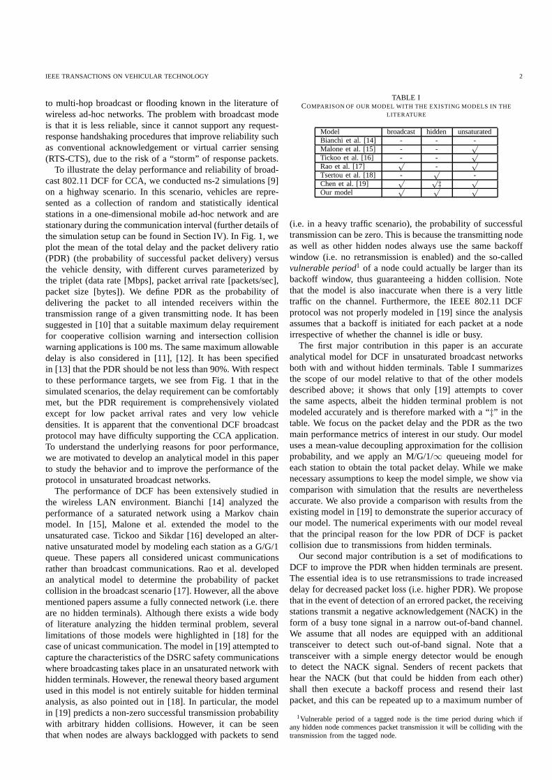
To illustrate the delay performance and reliability of broad-cast 802.11 DCF for CCA, we conducted ns-2 simulations [9]on a highway scenario. In this scenario, vehicles are repre-sented as a collection of random and statistically identicalstations in a one-dimensional mobile ad-hoc network and arestationary during the communication interval (further details ofthe simulation setup can be found in Section IV). In Fig. 1, weplot the mean of the total delay and the packet delivery ratio(PDR) (the probability of successful packet delivery) versusthe vehicle density, with different curves parameterized bythe triplet (data rate [Mbps], packet arrival rate [packets/sec],packet size [bytes]). We define PDR as the probability ofdelivering the packet to all intended receivers within thetransmission range of a given transmitting node. It has beensuggested in [10] that a suitable maximum delay requirementfor cooperative collision warning and intersection collisionwarning applications is 100 ms. The same maximum allowabledelay is also considered in [11], [12]. It has been specifiedin [13] that the PDR should be not less than 90%. With respectto these performance targets, we see from Fig. 1 that in thesimulated scenarios, the delay requirement can be comfortablymet, but the PDR requirement is comprehensively violatedexcept for low packet arrival rates and very low vehicledensities. It is apparent that the conventional DCF broadcastprotocol may have difficulty supporting the CCA application.To understand the underlying reasons for poor performance,we are motivated to develop an analytical model in this paperto study the behavior and to improve the performance of theprotocol in unsaturated broadcast networks.
The performance of DCF has been extensively studied inthe wireless LAN environment. Bianchi [14] analyzed theperformance of a saturated network using a Markov chainmodel. In [15], Malone et al. extended the model to theunsaturated case. Tickoo and Sikdar [16] developed an alter-native unsaturated model by modeling each station as a G/G/1queue. These papers all considered unicast communicationsrather than broadcast communications. Rao et al. developedan analytical model to determine the probability of packetcollision in the broadcast scenario [17]. However, all the abovementioned papers assume a fully connected network (i.e. thereare no hidden terminals). Although there exists a wide bodyof literature analyzing the hidden terminal problem, severallimitations of those models were highlighted in [18] for thecase of unicast communication. The model in [19] attempted tocapture the characteristics of the DSRC safety communicationswhere broadcasting takes place in an unsaturated network withhidden terminals. However, the renewal theory based argumentused in this model is not entirely suitable for hidden terminalanalysis, as also pointed out in [18]. In particular, the modelin [19] predicts a non-zero successful transmission probabilitywith arbitrary hidden collisions. However, it can be seenthat when nodes are always backlogged with packets to send
TABLE ICOMPARISON OF OUR MODEL WITH THE EXISTING MODELS IN THE
LITERATURE
Model broadcast hidden unsaturatedBianchi et al. [14] - - -Malone et al. [15] - -
√
Tickoo et al. [16] - -√
Rao et al. [17]√
-√
Tsertou et al. [18] -√
-Chen et al. [19]
√ √‡
√
Our model√ √ √
(i.e. in a heavy traffic scenario), the probability of successfultransmission can be zero. This is because the transmitting nodeas well as other hidden nodes always use the same backoffwindow (i.e. no retransmission is enabled) and the so-calledvulnerable period1 of a node could actually be larger than itsbackoff window, thus guaranteeing a hidden collision. Notethat the model is also inaccurate when there is a very littletraffic on the channel. Furthermore, the IEEE 802.11 DCFprotocol was not properly modeled in [19] since the analysisassumes that a backoff is initiated for each packet at a nodeirrespective of whether the channel is idle or busy.
The first major contribution in this paper is an accurateanalytical model for DCF in unsaturated broadcast networksboth with and without hidden terminals. Table I summarizesthe scope of our model relative to that of the other modelsdescribed above; it shows that only [19] attempts to coverthe same aspects, albeit the hidden terminal problem is notmodeled accurately and is therefore marked with a “‡” in thetable. We focus on the packet delay and the PDR as the twomain performance metrics of interest in our study. Our modeluses a mean-value decoupling approximation for the collisionprobability, and we apply an M/G/1/∞ queueing model foreach station to obtain the total packet delay. While we makenecessary assumptions to keep the model simple, we show viacomparison with simulation that the results are neverthelessaccurate. We also provide a comparison with results from theexisting model in [19] to demonstrate the superior accuracyofour model. The numerical experiments with our model revealthat the principal reason for the low PDR of DCF is packetcollision due to transmissions from hidden terminals.
Our second major contribution is a set of modifications toDCF to improve the PDR when hidden terminals are present.The essential idea is to use retransmissions to trade increaseddelay for decreased packet loss (i.e. higher PDR). We proposethat in the event of detection of an errored packet, the receivingstations transmit a negative acknowledgement (NACK) in theform of a busy tone signal in a narrow out-of-band channel.We assume that all nodes are equipped with an additionaltransceiver to detect such out-of-band signal. Note that atransceiver with a simple energy detector would be enoughto detect the NACK signal. Senders of recent packets thathear the NACK (but that could be hidden from each other)shall then execute a backoff process and resend their lastpacket, and this can be repeated up to a maximum number of
1Vulnerable period of a tagged node is the time period during which ifany hidden node commences packet transmission it will be colliding with thetransmission from the tagged node.
IEEE TRANSACTIONS ON VEHICULAR TECHNOLOGY 3
0 50 100 150 200
0.2
0.25
0.3
0.35
0.4
0.45
0.5
Vehicle Density (vehicles/km)
Mea
n D
elay
(m
s)
(24,10,400)
(12,2,200)
(24,10,200)
(a)
0 50 100 150 200
0.4
0.5
0.6
0.7
0.8
0.9
1
Vehicle Density (vehicles/km)
Pac
ket D
eliv
ery
Rat
io
(24,10,400)
(24,10,200)
(12,2,200)
(b)
Fig. 1. Total delay and Packet Delivery Ratio using the following parameter set: (data rate [Mbps], packet arrival rate [packets/sec], packet size [bytes])
retransmissions. To reduce the chance of successive collisionsbetween hidden terminals, we distinguish between sendersaccording to the delay in receiving the busy tone, and assigndifferent backoff contention windows depending on whetherthe delay is short or long. We extend our DCF analytical modelto the enhanced protocol, and show that our extended modelpreserves predictive accuracy. Most importantly, our numericalexperiments confirm that compared to DCF, the enhancedprotocol gives a higher PDR for a wider range of vehicledensities and packet arrival rates, while maintaining the delaybelow the required threshold level. The results demonstratethat our enhancement can bring the standard a step closer tothe ultimate solution for safety applications, which is to meetthe strict QoS requirements under arbitrary vehicle densitiesand network conditions.
The rest of this paper is organized as follows. In Sec-tion II, we provide an overview of DSRC challenges andstandardization activities. In Section III, we describe ouranalytical model for DCF. We verify the accuracy of our DCFmodel by comparison with simulation in Section IV. Then inSection V, we describe our enhanced protocol and illustrateits performance. Finally, we conclude the paper in Section VI.
II. DSRC CHALLENGES AND STANDARDIZATION
ACTIVITIES
The primary goals of emerging DSRC systems are toenhance road safety and to improve transportation efficiency.In this paper, we focus on the safety aspect. Road safety issupported by the transmission of routine status messages andevent-driven emergency messages. Routine status messagesare sent periodically to neighboring vehicles to inform themof the current status of the originating vehicle (e.g. locationspeed, direction), whereby the receiving vehicles/drivers canthen anticipate any potential hazards (e.g. traffic jam ahead)and take necessary action. Event-driven safety messages aretriggered by rapid changes in vehicle behavior such as a hardbrake or an airbag explosion. To enable preventative action,
it is essential that both types of safety messages are receivedcorrectly by surrounding vehicles in a timely fashion.
One of the main challenges to achieve that objective is theloss of packets due to the presence of hidden terminals. Thisoccurs when a node is transmitting to a target node whilea third node that is unaware of the transmitter also startsits transmission and causes interference at the receiver. Thehidden terminal problem can afflict all decentralized wirelessnetworks, but is particularly severe in broadcast scenarios.In the broadcast case, there are multiple receivers for eachmessage, scattered in the transmission range of the sender.Anynode that is within sensing range of any receiver but outsidethe transmission range of the sender is a potential hiddenterminal. Therefore, the potential hidden terminal regionissignificantly larger than that for unicast communication.
The distinctive demands of DSRC applications, as well asthe unique operating environment involving fast moving vehi-cles, mean that specifically tailored communication protocolsare required for DSRC systems. The following subsections de-scribe the protocols being standardized by the IEEE standardsbody for DSRC.
A. IEEE WAVE
In 1999, the U.S. Federal Communication Commission(FCC) allocated 75MHz of spectrum in the 5.9 GHz bandfor DSRC use. The DSRC spectrum is divided into seven 10MHz wide channels, and a reserved 5 MHz channel. One ofthe 10 MHz channels, called the control channel, is restrictedto safety communications only, while the other channels areavailable for both safety and non-safety usage.
The initial effort at standardizing DSRC radio technologytook place in the ASTM 2313 working group [13]. Re-cently, the IEEE Wireless Access in Vehicular Environment(WAVE) project has published specifications for the FCCDSRC spectrum based on an OFDM air interface. IEEE WAVEencompasses the IEEE 802.11p standard [3] for the MAC andPHY, and the IEEE 1609 family of standards, which define the
IEEE TRANSACTIONS ON VEHICULAR TECHNOLOGY 4
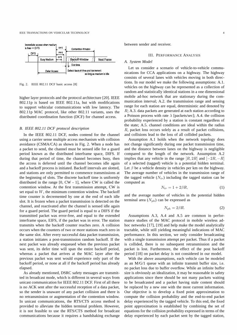
Fig. 2. IEEE 802.11 DCF basic access [8]
higher layer protocols and the protocol architecture [20].IEEE802.11p is based on IEEE 802.11a, but with modificationsto support vehicular communications with low latency. The802.11p MAC protocol, like other 802.11 variants, uses thedistributed coordination function (DCF) for channel access.
B. IEEE 802.11 DCF protocol description
In the IEEE 802.11 DCF, nodes contend for the channelusing a carrier sense multiple access mechanism with collisionavoidance (CSMA/CA) as shown in Fig. 2. When a node hasa packet to send, the channel must be sensed idle for a guardperiod known as the distributed interframe space, DIFS. Ifduring that period of time, the channel becomes busy, thenthe access is deferred until the channel becomes idle againand a backoff process is initiated. Backoff intervals are slotted,and stations are only permitted to commence transmissions atthe beginning of slots. The discrete backoff time is uniformlydistributed in the range [0, CW - 1], where CW is called thecontention window. At the first transmission attempt, CW isset equal toW , the minimum contention window. The backofftime counter is decremented by one at the end of each idleslot. It is frozen when a packet transmission is detected on thechannel, and reactivated after the channel is sensed idle againfor a guard period. The guard period is equal to a DIFS if thetransmitted packet was error-free, and equal to the extendedinterframe space, EIFS, if the packet was in error. The stationtransmits when the backoff counter reaches zero. A collisionoccurs when the counters of two or more stations reach zero inthe same slot. After every successful data packet transmission,a station initiates a post-transmission random backoff. Ifthenext packet was already enqueued when the previous packetwas sent, its defer time will span the entire backoff period,whereas a packet that arrives at the MAC layer after theprevious packet was sent would experience only part of thebackoff period, or none at all if the backoff period has alreadyelapsed.
As already mentioned, DSRC safety messages are transmit-ted in broadcast mode, which is different in several ways fromunicast communication for IEEE 802.11 DCF. First of all thereis no ACK sent after the successful reception of a data packet,so the sender is unaware of any packet collision and there isno retransmission or augmentation of the contention window.In unicast communications, the RTS/CTS access method isprovided to alleviate the hidden terminal problem. However,it is not feasible to use the RTS/CTS method for broadcastcommunications because it requires a handshaking exchange
between sender and receiver.
III. PERFORMANCEANALYSIS
A. System Model
Let us consider a scenario of vehicle-to-vehicle commu-nications for CCA applications on a highway. The highwayconsists of several lanes with vehicles moving in both direc-tions. In our model we make the following assumptions: A.1.vehicles on the highway can be represented as a collection ofrandom and statistically identical stations in a one dimensionalmobile ad-hoc network that are stationary during the com-munication interval; A.2. the transmission range and sensingrange for each station are equal, deterministic and denotedbyR; A.3. data packets are generated at each station according toa Poisson process with rateλ [packets/sec]; A.4. the collisionprobability experienced by a station is constant regardless ofthe state; A.5. channel conditions are ideal within the radiusR, packet loss occurs solely as a result of packet collisions,and collisions lead to the loss of all collided packets.
Assumption A.1 holds when the network topology doesnot change significantly during one packet transmission time,and the distance between lanes on the highway is negligiblecompared to the length of the network. Assumption A.2implies that any vehicle in the range[R, 2R] and [−2R,−R]of a selected (tagged) vehicle is a potential hidden terminal.Let β be a vehicle density in vehicles per km on the highway.The average number of vehicles in the transmission range ofthe tagged vehicle (Ntr) including the tagged station can becomputed as
Ntr = 1 + 2βR, (1)
and the average number of vehicles in the potential hiddenterminal area (Nph) can be expressed as
Nph = 2βR. (2)
Assumptions A.3, A.4 and A.5 are common in perfor-mance studies of the MAC protocol in mobile wireless ad-hoc networks [17], [19] and help make the model analyticallytractable, while still yielding meaningful indications ofMACperformance. In this section, we only consider broadcastingwith a single transmission attempt per packet. Thus if a packetis collided, there is no subsequent retransmission and thepacket is lost. Furthermore, the effect of the post backoffperiod [18] on packet delay is not considered in our model.
With the above assumptions, each vehicle can be modeledas an M/G/1 queue with an infinite transmit buffer size, i.e.no packet loss due to buffer overflow. While an infinite buffersize is obviously an idealization, it may be reasonable in safetyapplications since there should be not many packets waitingto be broadcasted and a packet having stale content shouldbe replaced by a new one with the most current information.Our objective is to develop a fixed point approximation tocompute the collision probability and the end-to-end packetdelay experienced by the tagged vehicle. To this end, the fixedpoint approximation is established by combining the set ofequations for the collision probability expressed in termsof thedelay experienced by each packet sent by the tagged station,

IEEE TRANSACTIONS ON VEHICULAR TECHNOLOGY 5
with an opposing set of equations for the delay expressed interms of the collision probability. We derive the former setofequations in subsection III-B and the latter in subsection III-D.
B. Collision Probability
In this subsection, we derive the collision probability with-out accounting for hidden terminals (i.e. “direct” collisionsonly), and in the next subsection, we modify the model to al-low for hidden terminals. To calculate the collision probabilityof safety messages, first we identify three scenarios that canconfront a newly-generated packet in a vehicle operating inanunsaturated network as following:
1) A packet arrives to an empty buffer and finds the channelidle for a DIFS period.
2) A packet arrives to an empty buffer and finds the channelbusy.
3) A packet arrives to a non-empty buffer.
For the first case, the vehicle immediately sends the packetwithout performing a backoff. In this case, a collision canoccur only when another packet is generated at some othervehicle within the propagation delay. As the propagation delayin the studied transmission range is negligible, we can ignoreany collisions of this type. As described before, we modeleach station as an M/G/1/∞ queue and defineρ as the queueutilization expressed as
ρ = λE[S], (3)
where E[S] is the average service time, to be derived insubsection III-E. From standard M/G/1/∞ queueing theory,the probability that the buffer is empty is given by1− ρ. Wealso definepb as the probability that the channel is sensed busywhen a new packet arrives. Therefore, assuming independencebetween an empty buffer and a busy channel, the probabilityof finding an empty buffer and sensing the channel idle is(1− ρ)(1− pb). The expression forpb will be derived later inthis section.
In the second case, the joint probability of a packet arrivalto an empty buffer and the channel being busy due to trans-mission by other vehicles is(1 − ρ)pb.
For the last case, the probability of a packet arrival to a non-empty buffer isρ. Note that for the last two cases, the packetmust undergo the backoff process before it is transmitted. Afterthe backoff counter reaches zero, the tagged vehicle sends thepacket in the following slot, and if another vehicle sends apacket at the same slot, a collision occurs and the packets arelost.
Let τ be the probability that a vehicle attempts to transmitin an arbitrary slot given that it has a packet in the queue. Weapproximateτ using a mean-value approach, where we assumethatτ is the same for every slot and related to the reciprocal ofthe mean backoff period. Specifically, lettingW be the averagenumber of backoff slots preceding a transmission, we let
τ =1
W + 1.
For any vehicle other than the tagged vehicle, the probabilityof transmitting in any arbitrary slot isρτ . A collision occurs
when any of theNtr − 1 vehicles transmit in the same slot asthe tagged vehicle given that the tagged vehicle sees eitherofthe last two cases. So, the collision probability is given by
pdc = (1− (1− ρ)(1− pb))(1 − (1− ρτ)Ntr−1), (4)
and the packet delivery ratio as
PDR = 1− pdc. (5)
Next, we express the probability that the channel is sensedbusy when a new packet arrives,pb, as
pb = (Ntr − 1)λT (1− pdc/2), (6)
wherepdc is the conditional collision probability in (4) andT is the complete transmission time of a packet includingthe DIFS period. Equation (6) is based on quantifying thetraffic load on the channel. As we haveNtr − 1 vehiclesother than the tagged vehicle transmittingλ [packets/sec], ifthere is no collision, then all the packet transmissions shouldtake(Ntr−1)λT time each second. However, with a collisionprobability of pdc, (Ntr − 1)λpdc packets will be involved incollisions. If we only consider collisions among two packets,the transmission time to send the collided packets would be(Ntr − 1)λTpdc/2. Adjusting for this collision period we get(6).
C. Hidden Terminal Case
In the previous section, we obtained the collision probabilityassuming no hidden terminals. Now we present an approachto calculate the probability of collision when hidden terminalsare present. We note that two necessary conditions must besatisfied to avoid collisions between packets from hiddenterminals and from the tagged vehicle. Firstly, when the taggedvehicle starts its transmission, none of the hidden terminalscan be in thetransmitting state; we denote this event asH1.We say that a hidden terminal is in the transmitting state if itis either transmitting a packet or deferring for a DIFS periodassociated with an immediate packet transmission. Secondly,after the tagged vehicle starts its transmission assumingH1,none of the hidden terminals should start transmitting untilafter the tagged vehicle is finished; we denote this event asH2.
For eventH1, we follow a similar argument as (6) tocalculate the probability of finding all hidden terminals inthe non-transmitting state. We note that the eventH1 is thecomplement of the event of finding at least one hidden terminalin the transmitting state; we denote this complementary eventas H1. As we haveNph hidden terminals transmittingλ[packets/sec], if there is no direct collision, then all thepackettransmissions should takeNphλT time each second. However,due to direct collisions among hidden terminals some packettransmissions will overlap. With the direct collision probabilityof pdc, we haveNphλpdc such overlapping packets. If weassume no direct collision involving three or more packets,the transmission time to send the collided packets wouldbe NphλTpdc/2. Adjusting for this collision period we canexpress the probability of eventH1 as
P (H1) = 1− P (H1) = 1−NphλT (1− pdc/2). (7)

IEEE TRANSACTIONS ON VEHICULAR TECHNOLOGY 6
For eventH2, we need to calculate the probability that apacket is generated by the hidden terminal after the taggedvehicle starts its transmission and eventually collides with thetransmission of the tagged vehicle. Note that packets generatedat the hidden terminal in the last time portion of one DIFSperiod of the tagged vehicle’s transmission will not collidebecause the hidden terminal will still be deferring for a DIFSperiod when the tagged vehicle finishes its transmission. Sincepackets arrive in each station’s transmit buffer accordingtoa Poisson process, the combined packet arrival from all thehidden terminals is also Poisson with rateλNph [packets/sec].Therefore, the conditionH2 is met if no packet is generatedat any of the hidden terminals duringtdata− tdifs period andthe probability of such an event is expressed as
P (H2) = e−λNph(tdata−tdifs), (8)
wheretdata is the transmission time of a packet andtdifs isthe duration of DIFS period.
Considering the fact that direct collisions and collisionsdueto hidden terminals are independent of each other, we modifythe collision probability (4) to account for the hidden collisionsas follows:
pc = 1− (1− pdc) · P (H1) · P (H2). (9)
Recall that, the PDR is defined as the probability of deliveringthe packet to all intended receivers within the transmissionrange of a given transmitting node. As such, the packetdelivery ratio for hidden terminal case can be expressed as
PDR = 1− pc. (10)
D. Expression for the Delay
In this section, we derive an expression for the packet delayusing probabilistic arguments. The total delay (or sojourntime)experienced by a packet of a tagged vehicle includes thewaiting time of the packet in the queue, the access delay andthe complete time to transmit the packet. The access delayis defined as the time interval between the instant the packetreaches the head of the queue, to the instant when the packettransmission starts. We denote the total delay of the packetbyD and write it as
D = Q+ S = Q+A+ T, (11)
whereQ andA are random variables (r.v.’s) representing thequeueing delay and access delay. For each packet transmission,the channel is occupied for the duration of the actual packettransmission(tdata) and one DIFS; recall that we define thecomplete transmission timeT as the sum of the actual packettransmission time and one DIFS period. We also define theservice time of the queueS as the sum of the access delayAand the transmission delayT .
To determine the access delay, we refer to the previous threecases:
1) A packet arrives to an empty buffer and finds the channelidle with probability(1 − ρ)(1 − pb). The access delayin this case is zero as the tagged vehicle transmits thepacket without any backoff.
2) A packet arrives to an empty buffer but finds the channelbusy with probability(1− ρ)pb. The vehicle must waituntil the ongoing transmission is finished and thenperform a backoff before transmitting the packet.
3) A packet arrives to a non-empty buffer with probabilityρ and when it reaches the head of the queue, a backoffis performed before transmitting the packet.
Since, the probability of a non-empty buffer isρ, and theprobability of finding the channel busy ispb, we can expressthe access delay according to the above three cases as
A =
0 w.p. (1− ρ)(1 − pb),
B + TRes w.p. (1− ρ)pb,
B w.p. ρ.
(12)
where TRes is the residual lifetime of an ongoing packettransmission,B is the total backoff duration including periodswhen the backoff counter is suspended, and the notation ‘w.p.’stands for ‘with probability’.
During the backoff process, every slot can be interrupted bysuccessful transmissions or collisions of packets transmitted byother vehicles. During the interruption, the backoff counter issuspended and when the backoff counter is resumed, it startsfrom the beginning of the interrupted slot. For simplicity,weassume every backoff slot can be interrupted at most once.This simplification should not have a significant impact onaccuracy, since the probability of multiple interruptionsto thesame slot is small. Thus, we can expressB as a random sum
B =U∑
n=1
(σ + Y ), (13)
whereσ represents the duration of a backoff slot,Y is theinterruption period per slot, andU is the backoff counter valuewhich is uniformly distributed in the range[0,W − 1].
If no other vehicle transmits in a given slot, an interruptiondoes not occur andY equals zero. If one or more vehiclestransmit in that slot, then the tagged vehicle will suspend itsbackoff process for the duration of the complete transmission,T . Recall that the probability that a vehicle attempts to trans-mit in an arbitrary slot given that it has a packet in its bufferis given byτ and the probability that the buffer is non-emptyis ρ. Therefore, the probability of a vehicle transmitting in anarbitrary slot isρτ and a backoff slot of the tagged vehicle isinterrupted when any of the otherNtr − 1 vehicles transmitin that slot with probability1− (1− ρτ)Ntr−1. Therefore, wecan writeY as
Y =
{
0 w.p. (1 − ρτ)Ntr−1,
T w.p. 1− (1 − ρτ)Ntr−1.(14)
where1− (1− ρτ)Ntr−1 is the probability that a slot is busydue to transmissions by other vehicles.
E. Mean and Standard Deviation
In this section, we determine the mean and standard devi-ation of the service time and the mean of the total delay. Weexpress them using means and variances of the constituent

IEEE TRANSACTIONS ON VEHICULAR TECHNOLOGY 7
random variables. From (11), sinceA andT are independent,we can write
E[S] = E[A] + E[T ], (15)
StdDev[S] =√
Var[S] =√
Var[A] + Var[T ], (16)
whereE[X ], StdDev[X ] andVar[X ] denotes the mean, stan-dard deviation and variance of the random variableX .
Considering fixed length packets for all vehicles, we have
E[T ] = T,
Var[T ] = 0.(17)
From (12) the mean and variance ofA can be written as
E[A] = (1− ρ)pb(E[B] + E[TRes]) + ρE[B], (18)
Var[A] = (1− ρ)(1− pb) E[A]2
+ (1 − ρ)pb(Var[B] + Var[TRes]
+ (E[A]− E[B]− E[TRes])2)
+ ρ(Var[B] + (E[A]− E[B])2).
(19)
To calculate the mean and variance of the residual lifetimeof an ongoing transmission,TRes, we first determine theprobability distribution function ofTRes. Note that the inter-arrival time of packets generated at each vehicle follows amemoryless exponential distribution with rateλ. So the inter-val between the starting time of an ongoing transmission andthe arrival of a new packet at the tagged vehicle also followsan exponential distribution and we define it asX ∼ 1− e−λt.Therefore, we can represent the distribution ofTRes as theremaining transmission time,Y = T − X , conditioned onX ≤ T .
Now, the probability distribution function ofY can beexpressed asFY (y) = 1−FX(T − y), whereFZ(·) here rep-resents the distribution function ofZ. Applying the conditionX ≤ T , we get
FY |X≤T (y) = 1− FX|X≤T (T − y) =e−λ(T−y) − e−λT
1− e−λT.
(20)
Differentiating (20), we obtain the probability density func-tion as
fY |X≤T (y) =λe−λ(T−y)
1− e−λT. (21)
Now, we can obtain the mean and variance ofTRes from(21) as follows:
E[TRes] = E[Y |X ≤ T ] =
∫ T
0
yfY |X≤T (y)dy
=T
1− e−λT−
1
λ,
(22)
E[T 2Res] = E[Y 2|X ≤ T ] =
∫ T
0
y2fY |X≤T (y)dy
=T 2 − 2T/λ
1− e−λT+
2
λ2,
(23)
Var[TRes] = E[T 2Res]− E[TRes]
2 =1
λ2−
T 2e−λT
(1− e−λT )2.
(24)
TABLE IIDSRC SYSTEM PARAMETERS
Parameter ValueW 16Range,R 0.5 kmSlot size,σ 16 µs
SIFS 32 µs
PHY preamble 32 µs
PLCP header 8 µs
Vehicle density,β 10 – 200 vehicles/kmData rate,Rd 12, 24 MbpsPacket arrival rate,λ 2, 10 packets/secPacket length,P 200, 400 bytes
Using well-known identities for the mean and variance ofa random sum [21], it follows from (13) that
E[B] = (σ + E[Y ]) E[U ], (25)
Var[B] = Var[Y ] E[U ] + (σ + E[Y ])2 Var[U ]. (26)
As U is a r.v. which is uniformly distributed in the range[0,W − 1], we have
E[U ] = W =W − 1
2, (27)
Var[U ] =W 2 − 1
12. (28)
For the interruption timeY , we can calculate the mean andvariance from (14) as
E[Y ] = (1− (1 − ρτ)Ntr−1)T, (29)
Var[Y ] = (1− (1 − ρτ)Ntr−1)((1 − ρτ)Ntr−1)T 2. (30)
Thus, based on (15)–(30), we can derive the mean andstandard deviation of the service time in terms ofpb and ρ.Now (3), (4), (6), and (15) constitute a non-linear system ofequations that can be solved iteratively to calculateρ, pb, pdc,and E[S]. Using those computed values we can derive themean queueing delay,E[Q]. Using the well-known result forthe M/G/1 queue, we obtain
E[Q] =λ(Var[S] + E[S]2)
2(1− λE[s]), (31)
whereVar[S] is calculated from (16). The mean total delay isthen given by
E[D] = E[Q] + E[S]. (32)
IV. M ODEL VALIDATION AND DISCUSSION
In this section, we present the simulation setup used tovalidate our analytical model and present the validation results.We used the ns simulator (version 2.28) [9] to simulate andobtain packet delay and PDR in a DSRC environment undervarious conditions. We adopted the patch for ns-2.28 providedin [22] where they fixed the following bug. According to theIEEE802.11 specification [8] (see Fig. 2), if the medium issensed idle when a packet arrives at the MAC layer, the packetcan be transmitted after an idle period of DIFS without anybackoff. However, in the standard distribution of ns-2.28,abackoff is always started irrespective of whether the channelis idle or busy.
IEEE TRANSACTIONS ON VEHICULAR TECHNOLOGY 8
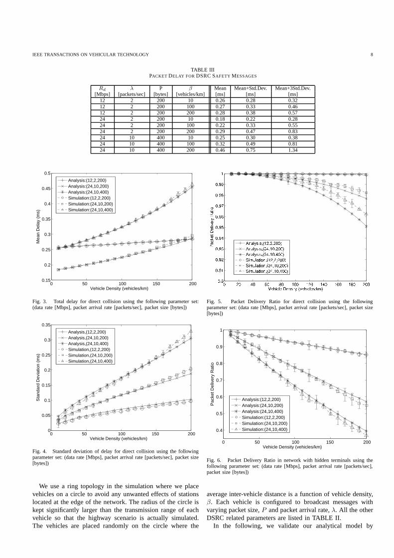
TABLE IIIPACKET DELAY FOR DSRC SAFETY MESSAGES
Rd λ P β Mean Mean+Std.Dev. Mean+3Std.Dev.[Mbps] [packets/sec] [bytes] [vehicles/km] [ms] [ms] [ms]
12 2 200 10 0.26 0.28 0.3212 2 200 100 0.27 0.33 0.4612 2 200 200 0.28 0.38 0.5724 2 200 10 0.18 0.22 0.2824 2 200 100 0.22 0.33 0.5524 2 200 200 0.29 0.47 0.8324 10 400 10 0.25 0.30 0.3824 10 400 100 0.32 0.49 0.8124 10 400 200 0.46 0.75 1.34
0 50 100 150 2000.15
0.2
0.25
0.3
0.35
0.4
0.45
0.5
Vehicle Density (vehicles/km)
Mea
n D
elay
(m
s)
Analysis:(12,2,200)Analysis:(24,10,200)Analysis:(24,10,400)Simulation:(12,2,200)Simulation:(24,10,200)Simulation:(24,10,400)
Fig. 3. Total delay for direct collision using the followingparameter set:(data rate [Mbps], packet arrival rate [packets/sec], packet size [bytes])
0 50 100 150 2000
0.05
0.1
0.15
0.2
0.25
0.3
0.35
Vehicle Density (vehicles/km)
Sta
ndar
d D
evia
tion
(ms)
Analysis,(12,2,200)Analysis,(24,10,200)Analysis,(24,10,400)Simulation,(12,2,200)Simulation,(24,10,200)Simulation,(24,10,400)
Fig. 4. Standard deviation of delay for direct collision using the followingparameter set: (data rate [Mbps], packet arrival rate [packets/sec], packet size[bytes])
We use a ring topology in the simulation where we placevehicles on a circle to avoid any unwanted effects of stationslocated at the edge of the network. The radius of the circle iskept significantly larger than the transmission range of eachvehicle so that the highway scenario is actually simulated.The vehicles are placed randomly on the circle where the
Fig. 5. Packet Delivery Ratio for direct collision using thefollowingparameter set: (data rate [Mbps], packet arrival rate [packets/sec], packet size[bytes])
0 50 100 150 200
0.4
0.5
0.6
0.7
0.8
0.9
1
Vehicle Density (vehicles/km)
Pac
ket D
eliv
ery
Rat
io
Analysis:(12,2,200)Analysis:(24,10,200)Analysis:(24,10,400)Simulation:(12,2,200)Simulation:(24,10,200)Simulation:(24,10,400)
Fig. 6. Packet Delivery Ratio in network with hidden terminals using thefollowing parameter set: (data rate [Mbps], packet arrivalrate [packets/sec],packet size [bytes])
average inter-vehicle distance is a function of vehicle density,β. Each vehicle is configured to broadcast messages withvarying packet size,P and packet arrival rate,λ. All the otherDSRC related parameters are listed in TABLE II.
In the following, we validate our analytical model by
IEEE TRANSACTIONS ON VEHICULAR TECHNOLOGY 9
comparing the numerical results with the simulation results.We present results for the mean of the total delay, the standarddeviation of the access delay, and the PDR. Another objectiveof our numerical experiments is to investigate the effect ofdifferent load conditions on the delay and PDR. All thesimulation results are plotted with 95% confidence intervals.
We first present and discuss results for the direct collisioncase. In Fig. 3, we plot the mean of the total delay (32)as a function of vehicle density,β, with different curvesparameterized by the data rateRd [Mbps], packet sizeP[bytes], and packet arrival rateλ [packets/sec]. Observe thatour analytical model agrees well with the simulation results.In the plotted range, the mean delay increases almost linearlywith the vehicle density, with the slope for theλ = 10 casebeing larger compared to theλ = 2 case. The biggest delayobserved is less than 0.5 ms which is well below the maximumdelay constraint of 100 ms for safety applications [10].
In Fig. 4, we study the accuracy of our model in terms of thestandard deviation. Note that we use the standard deviationofthe service time in (16) as a proxy for the standard deviationof the total delay. We observe from the figure that the standarddeviation for all cases is nearly zero for low vehicle densities.This is because the channel is mostly idle and no backoff isrequired by the vehicles. With increasing vehicle density,thestandard deviation increases almost linearly. We note thattheanalysis matches well with the simulation results for all cases.
Next, we plot the packet delivery ratio for direct collisionsin Fig. 5, where the analytical results are computed accordingto (5). The analysis provides a reasonable match with thesimulation results. For theλ = 2 case, we see that thePDR is above 99% for all vehicle densities; however, for theλ = 10 case, the PDR drops with increasing vehicle density.Nevertheless, the PDR requirement of 90% stipulated by theASTM [13] is fulfilled.
For the hidden terminal case, the distribution of the packetdelay is the same as for the direct collision case. This isbecause there is no retransmission and the presence of hiddenterminals does not affect the backoff process of the taggedvehicle. For this reason we omit the results for the meanand standard deviation of the delay when there are hiddenterminals.
In Fig. 6, we plot results for the PDR according to (10)which accounts for hidden terminals and compare them withsimulation. The PDR is above 90% for all cases under lightload (β ≤ 200) but drops linearly with increasing vehicledensity. For higher vehicle densities, the PDR eventually dropsbelow the reliability requirement of 90% for DSRC safetyapplications. We also observe that the PDRs for theλ = 10cases are much worse than that of theλ = 2 case. From Figs.5 and 6, we can compare the PDR values obtained for thehidden terminal case with that for the direct collision case. Ourcomparative results show that packet collision due to hiddenterminals is the major source of collisions and can reduce thePDR by up to 25%.
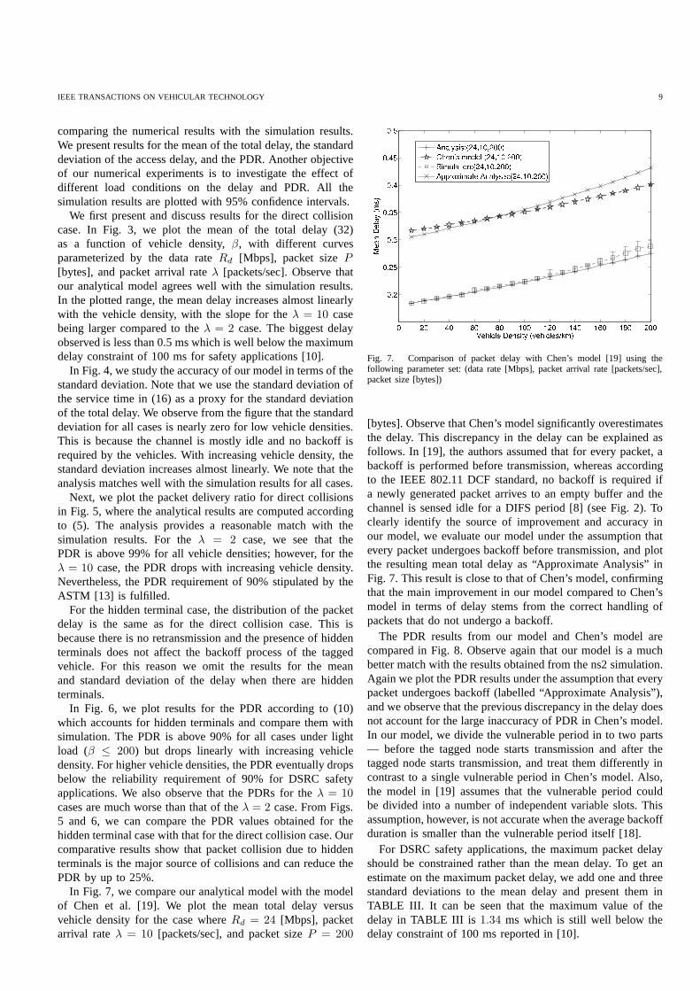
In Fig. 7, we compare our analytical model with the modelof Chen et al. [19]. We plot the mean total delay versusvehicle density for the case whereRd = 24 [Mbps], packetarrival rateλ = 10 [packets/sec], and packet sizeP = 200
Fig. 7. Comparison of packet delay with Chen’s model [19] using thefollowing parameter set: (data rate [Mbps], packet arrivalrate [packets/sec],packet size [bytes])
[bytes]. Observe that Chen’s model significantly overestimatesthe delay. This discrepancy in the delay can be explained asfollows. In [19], the authors assumed that for every packet,abackoff is performed before transmission, whereas accordingto the IEEE 802.11 DCF standard, no backoff is required ifa newly generated packet arrives to an empty buffer and thechannel is sensed idle for a DIFS period [8] (see Fig. 2). Toclearly identify the source of improvement and accuracy inour model, we evaluate our model under the assumption thatevery packet undergoes backoff before transmission, and plotthe resulting mean total delay as “Approximate Analysis” inFig. 7. This result is close to that of Chen’s model, confirmingthat the main improvement in our model compared to Chen’smodel in terms of delay stems from the correct handling ofpackets that do not undergo a backoff.
The PDR results from our model and Chen’s model arecompared in Fig. 8. Observe again that our model is a muchbetter match with the results obtained from the ns2 simulation.Again we plot the PDR results under the assumption that everypacket undergoes backoff (labelled “Approximate Analysis”),and we observe that the previous discrepancy in the delay doesnot account for the large inaccuracy of PDR in Chen’s model.In our model, we divide the vulnerable period in to two parts— before the tagged node starts transmission and after thetagged node starts transmission, and treat them differently incontrast to a single vulnerable period in Chen’s model. Also,the model in [19] assumes that the vulnerable period couldbe divided into a number of independent variable slots. Thisassumption, however, is not accurate when the average backoffduration is smaller than the vulnerable period itself [18].
For DSRC safety applications, the maximum packet delayshould be constrained rather than the mean delay. To get anestimate on the maximum packet delay, we add one and threestandard deviations to the mean delay and present them inTABLE III. It can be seen that the maximum value of thedelay in TABLE III is 1.34 ms which is still well below thedelay constraint of 100 ms reported in [10].

IEEE TRANSACTIONS ON VEHICULAR TECHNOLOGY 10
Fig. 8. Comparison of Packet Delivery Ratio with Chen’s model in networkwith hidden terminals [19] using the following parameter set: (data rate[Mbps], packet arrival rate [packets/sec], packet size [bytes])
V. EXTENSION OF THEMODEL
A. Existing Solutions
Our results from the previous section suggest that the DCFprotocol satisfies the delay constraint but its PDR performanceis susceptible to hidden terminals. In the following we reviewand discuss some possible enhancements from the literaturethat aim to improve the broadcasting performance.
In [23] and [24], retransmission of a broadcast message isproposed to improve the reliability at the MAC layer. Repeat-ing messages either flood a network by piggybacking [23], orthe repetition is carried out by an individual node randomlyover the lifetime of a packet [24]. The main drawback ofthis approach is that it may cause too many collisions due torepetition of messages and eventually the PDR performancewould degrade as shown in [25].
Significant efforts have also been made to solve the hiddenterminal problem for broadcast. One approach is to extendthe RTS/CTS mechanism used for unicast to broadcast. Dueto multiple receivers in the broadcast environment, additionalstate or message type information is proposed to be includedinthe RTS/CTS mechanism for broadcast [26], [27]. As a result,the extended RTS/CTS mechanism becomes complex and doesnot guarantee absolute reliability. In [28] the authors proposea request-to-broadcast/clear-to-broadcast (RTB/CTB) schemeto alleviate the hidden terminal problem. To support reliablecommunication, the CTB packets are sent in the form of anenergy burst (a so-called black-burst or jamming signal [29])whose length is proportional to the distance between thereceiver and the sender. The protocol with RTB/CTB, however,is sensitive to topology changes. Broadcast RTS/CTS byway of multiple unicast is also proposed in [30] with somesignificant overhead.
Previous ideas for mitigating the hidden terminal problemfor unicast communications could also be applied for broadcastsuch as a busy tone in [31], [32], a contention tone in [33] ora so-called black burst in [29]. A combination of a busy tone
and RTS/CTS is also proposed in [34] to be used in the datachannel for broadcast communication.
On the other hand, there have been several proposals [35],[36] advocating the use of an acknowledgement (ACK) tostrive for a reliable broadcast without directly addressing thehidden terminal problem. Most of these schemes, however,attempt to send multiple positive ACK messages from multiplereceivers which could cause even more collisions and per-formance degradation. Exceptions are proposals in [27], [37]where the authors suggest the use of a negative ACK (NACK)together with RTS/CTS for reliable communication. Finally,there are also some other enhancements proposed in [38] todynamically tune the contention window or to give safetymessages priority over data packets by utilizing the enhancedDCF (or EDCA) mechanism in the IEEE 802.11e protocol.
B. Proposed Extension
In this section, we propose a simple retransmission schemefor broadcasting safety messages in the presence of hiddenterminals. We do not use any extended RTS/CTS or similarmechanisms to combat hidden terminals in broadcasting, butinstead rely on the retransmission of unsuccessful packetstoimprove reliability. To this end, we propose an out-of-bandreceiver-based busy tone to represent a NACK signal backto the source. The advantage is twofold. As the busy toneonly represents 1 bit information about the latest unsuccessfulpacket, a narrow bandwidth is sufficient for this purpose. Andto listen to the busy tone, a simple energy detector wouldsuffice rather than a fully-fledged transceiver. It is becausethe received signal strength of a packet that is corruptedby collision is generally higher than that of a disruptedpacket caused by noise. Furthermore, since packet collisionsmay involve transmissions from several hidden terminals, theNACK is sent by the receiver at the end of the collision periodwhen all the involved nodes have finished their transmission.
To avoid a new packet transmission from any collidingnodes before the receiver issues the NACK, we increase theDIFS duration to span one data transmission plus a NACKtransmission time. If the sender (or source) senses the busytone (i.e. hears a NACK), it will perform a backoff and sendthe last packet again until the packet is received by all thenodes or the maximum transmission attempt,r, is reached.In the latter case, the packet is dropped. Because we do notuse any handshake procedures (such as RTS/CTS) to avoidpotential hidden collisions (i.e. collisions that are caused byhidden terminals), the same hidden nodes can collide againin the following retransmission attempts. To avoid successivecollisions due to the same hidden terminals, we propose toseparate the retransmission attempts using different backoffwindows for different nodes involved in the collision. Thebackoff windows are larger compared to the transmissiontime of a packet. We assume that at most two nodes areinvolved in a hidden collision for a linear topology such asvehicles on a highway. As such, the node that hears a NACKimmediately after finishing its transmission knows that it isthe last node involved in the collision. This node will thenuse a larger contention window (four times of the normal

IEEE TRANSACTIONS ON VEHICULAR TECHNOLOGY 11
contention window is used in our study) to select its backoff,while others keep theirs unchanged. In this way, successivecollisions among the same hidden terminals will be reduced.
There are several advantages of our proposed protocol,including: (i) improved reliability of broadcast safety messagesin the presence of hidden terminals; (ii) mitigation of theimpact of hidden terminals in successive reattempts; and (iii)requirement of only a simple energy detector for the receptionof the NACK control packet (out-of-band signalling). Notethat (i) and (ii) are achieved without the need for a complexhandshaking mechanism proposed for broadcasting such asthe extended RTS/CTS or RTB/CTB mechanism mentioned insubsection V-A. Also the benefit of an NACK scheme is that,in a low loss environment the overhead is negligible, while wecan still improve the PDR in high loss scenarios.
In the next subsection we will investigate the effectivenessof this retransmission mechanism. To this end, the analyticalmodel developed in Section III is extended to cover the NACKbased retransmission protocol.
C. Enhanced Protocol Performance Analysis
In the case of retransmissions, the direct collision proba-bility calculated in (4) will be different for the first attemptand successive attempts. So, we distinguish between them bydenotingp′dc,i as the direct collision probability in theithattempt. For the first attempt, the probabilityp′dc,0 is similar to(4), but for the successive attempts, the probabilityp′dc,i wouldbe different as there is always a backoff between successiveattempts. So, we can express the direct collision probabilityas
p′dc,0 = (1− (1− ρ)(1 − p′b))(1 − (1− ρτ)Ntr−1), (33)
p′dc,i = p′dc,1 = (1 − (1− ρτ)Ntr−1), (34)
wherep′b represents the busy probability modified from (6) toincorporate retransmissions and it is expressed as
p′b = m(Ntr − 1)λT (1− p′dc/2), (35)
where,m is the expected number of attempts per packet (to bederived later) andp′dc is the average direct collision probabilitycalculated from
p′dc =p′dc,0 + (m− 1)p′dc,1
m. (36)
Furthermore, recall that two necessary conditionsH1 andH2 must be met to avoid hidden terminal collision. As ourDIFS period is now longer than the actual packet transmissiontime, those conditions are slightly changed.
The first condition,H1, assumes that when the tagged nodestarts its transmission no other hidden node can be in thetransmitting state. But due to the longer DIFS, it is nowpossible that when the tagged node starts its transmission,ahidden node is in the transmitting state waiting for the endof its DIFS and by the time it starts actual transmission thetagged node already finishes its transmission. For the secondcondition,H2, we note that ifH1 condition is met,H2 cannotoccur as by the time a hidden terminal is allowed to transmit(after a DIFS period), the tagged vehicle would have finished
its transmission. So, we only haveH1 in this case which wedifferentiate for the first attempt,H ′
1,0, and any successiveattempts,H ′
1,i. We define the probability of no hidden collisionfor the first attempt as
P (H ′1,0) = 1−mNphλ2tdata(1 − p′dc/2). (37)
If there is a collision in the first attempt between two nodes,one of the nodes will increase its contention window whichwill reduce the chance of successive collisions. Still we need tocalculate the probability of successive collision,pscv. We notethat a successive collision happens when the node with thelarger contention window starts transmitting before the othernode finishes its transmission. The mean time taken by the firstnode to finish its second transmission after the second nodefinishes its first transmission istdata/2 + (W − 1)/2. Now,denoting the larger contention window used by the secondnode asW ′, we can calculate the probability of successivecollision as
pscv =tdata/2 + (W − 1)σ/2
W ′σ. (38)
Now, we can assume that collision due to all other hiddennodes in the potential hidden range behave the same aspreviously. As such, the probability of no hidden collisionforthe successive attempts would be
P (H ′1,i) = P (H ′
1,1) = 1−m(Nph−1)λ2tdata(1−p′dc/2)pscv.(39)
Because direct collisions and collisions due to hidden termi-nals are independent, we get the expressions for the collisionprobabilities as
p′c,0 = 1− (1− p′dc,0)P (H ′1,0), (40)
p′c,i = 1− (1− p′dc,1)P (H ′1,1). (41)
The expected number of transmission attempts is given as
m = 1 + p′c,0 + p′c,0p′c,1 + p′c,0p
′2c,1 + · · ·+ p′c,0p
′r−2c,1
= 1 + p′c,01− p′r−1
c,1
1− p′c,1.
(42)
To calculate the packet delivery ratio, we note that a packetis dropped when all the transmission attempts fail. So, thePDR can be expressed as
PDR = 1− p′c,0p′r−1c,i . (43)
Now, we define the access delay conditioned on the numberretransmission asAi, where the packet transmission is com-pleted either successfully or unsuccessfully afteri retransmis-sion. With the collision probabilityp′c,i on each attempt, wecan calculate the probability ofi retransmission and expressthe access delayA as
A =
A0 w.p. (1− p′c,0),
Ai w.p. p′c,0p′i−1c,1 (1− p′c,1),
Ar−1 w.p. p′c,0p′r−2c,1 .
(44)

IEEE TRANSACTIONS ON VEHICULAR TECHNOLOGY 12
where the access delay for first transmission attempt,A0 issimilar to our previous model without retransmission
A0 =
0 w.p. (1− ρ)(1 − p′b),
B + TRes w.p. (1− ρ)p′b,
B w.p. ρ.
(45)
and access delay for successive transmission attempt,Ai(i ≥1) is defined as
Ai = Ai−1 +Bi + T
= A0 +i
∑
j=1
(Bj + T ),(46)
whereBi is the backoff duration forith retransmission at-tempt.
To calculateBi we note that for each successive transmis-sion attempt, the tagged node chooses its backoff counter withequal probability either in the range[0,W −1] or in the range[0,W ′−1], whereW ′ is the increased contention window. Thebackoff duration for the first case is the same asB defined in(13). For the second case, we define the backoff duration as
B′ =
U ′
∑
n=1
(σ + Y ), (47)
where U ′ is the backoff counter value which is uniformlydistributed in the range[0,W ′ − 1]. Now we can define thebackoff duration for theith retransmission attempt asBi.
Bi = B1 =
{
B w.p. 0.5,
B′ w.p. 0.5.(48)
From the above equation, the expected value and varianceof B1 can be calculated as
E[B1] = (E[B] + E[B′])/2, (49)
Var[B1] = (Var[B] + (E[B]− E[B1])2)/2
+ (Var[B′] + (E[B′]− E[B1])2)/2.
(50)
To get the expected value and variance of the access delay,we first calculate the expected value and variance of the accessdelay for each transmission attempt. For the first transmissionattempt, the distribution ofA0 in (45) is a conditional distri-bution, thus the we have
E[A0] = (1 − ρ)p′b(E[B] + E[TRes]) + ρE[B], (51)
Var[A0] = (1 − ρ)(1− p′b) E[A0]2
+ (1− ρ)p′b(Var[B] + Var[TRes]
+ (E[A0]− E[B]− E[TRes])2)
+ ρ(Var[B] + (E[A0]− E[B])2).
(52)
From (46), noting thatA0, Bj , T are all independent of eachother, we can calculate the expected value and variance of theaccess delay for any retransmission attempt,Ai as
E[Ai] = E[A0] + i(E[B1] + T ), (53)
Var[Ai] = Var[A0] + iVar[B1]. (54)
0 50 100 150 2000.2
0.4
0.6
0.8
1
1.2
1.4
1.6
1.8
2
Vehicle Density (vehicles/km)
Mea
n D
elay
(m
s)
Analysis:(12,2,200)Analysis:(24,10,200)Analysis:(24,10,400)Simulation:(12,2,200)Simulation:(24,10,200)Simulation:(24,10,400)
Fig. 9. Total delay for proposed protocol with three transmission attemptsusing the following parameter set: (data rate [Mbps], packet arrival rate[packets/sec], packet size [bytes])
Finally, putting the expected value and variance of theaccess delay for each transmission attempt,Ai in (44) wehave
E[A] = (1− p′c,0) E[A0] +
r−1∑
i=1
p′c,0p′i−1c,1 (1 − p′c,1) E[Ai]
+ p′c,0p′r−1c,1 E[Ar−1],
(55)
Var[A] = (1− p′c,0){Var[A0] + (E[A0])− E[A])2}
+r−1∑
i=1
p′c,0p′i−1c,1 (1− p′c,1){Var[Ai] + (E[Ai])− E[A])2}
+ p′c,0p′r−1c,1 {Var[Ar−1] + (E[Ar−1])− E[A])2}.
(56)
Next, we present analytical and simulation results for themean of the total delay and the PDR for our proposedretransmission protocol. For the following set of results,themaximum number of transmission attempts,r is set to 3. Werestrict our observations up to PDR=85% which covers therequired PDR threshold of 90% stipulated by the ASTM [13].
In Fig. 9, we plot the mean of the total delay using (32)as a function of vehicle density,β, with different curvesparameterized by the data rateRd [Mbps], packet sizeP[bytes], and packet arrival rateλ [packets/sec]. Observe thatour analytical model falls within the 95% confidence intervalof the simulation results. We note that for theλ = 2 casethe mean delay compared to Fig. 3 is proportionately largerdue to longer DIFS used for our proposed protocol. For theλ = 10 cases, the mean delay increases sharply because ofmore collision and subsequent retransmissions . However, thelargest delay observed is still less than 2 ms which is wellbelow the maximum delay constraint of 100 ms for safetyapplications [10].
In Fig. 10, we plot results for the PDR according to (43)and compare them with simulation. As mentioned earlier, weplot the PDR results in the range above PDR=85%. For the
IEEE TRANSACTIONS ON VEHICULAR TECHNOLOGY 13
0 50 100 150 2000.85
0.9
0.95
1
Vehicle Density (vehicles/km)
Pac
ket D
eliv
ery
Rat
io
Analysis:(12,2,200)Analysis:(24,10,200)Analysis:(24,10,400)Simulation:(12,2,200)Simulation:(24,10,200)Simulation:(24,10,400)
Fig. 10. Packet Delivery Ratio for proposed protocol with three transmissionattempts using the following parameter set: (data rate [Mbps], packet arrivalrate [packets/sec], packet size [bytes])
TABLE IVPDRWITH REDUCED TRANSMISSION RANGE USING24 [MBPS] DATA
RATE AND 10 [PACKETS/SEC] ARRIVAL RATE
P β Single Tx NACK based ReTx protocol[bytes] [vehicles/km] 500 m 500 m 250 m
20060 0.856 0.973 0.994100 0.774 0.898 0.984150 0.660 0.549 0.955
40060 0.792 0.903 0.97790 0.686 0.700 0.947120 0.582 0.207 0.900
λ = 2 case, we observe that the PDR is always better than 95%which is a significant improvement over Fig. 6. In particular,at β = 200 we observe a 10% increase in PDR value with theenhanced protocol. For the (24,10,200) and (24,10,400) casesin Fig. 10, the PDR eventually falls below 90% atβ = 60 andβ = 100, respectively. However, similar performance canonlybe observed in Fig. 6 using the original protocol at a muchlower density, atβ = 30 for (24,10,200) case, and atβ = 50for (24,10,400) case. Thus the enhanced protocol can supportup to two times the vehicle density for the required PDRthreshold. Overall, Fig. 10 shows a significant improvementin terms of PDR using our proposed protocol.
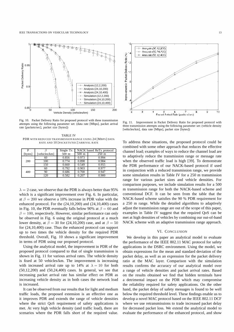
Using the analytical model, the improvement in PDR of theproposed protocol compared to that of single transmission isshown in Fig. 11 for various arrival rates. The vehicle densityis fixed at 50 vehicles/km. The improvement is increasingwith increased arrival rate up to 14% atλ = 10 for both(50,12,200) and (50,24,400) cases. In general, we see thatincreasing packet arrival rate has similar effect on PDR asincreasing vehicle density as in both cases the network loadis increased.
It can be observed from our results that for light and mediumtraffic loads, the proposed extension is an effective one asit improves PDR and extends the range of vehicle densitieswhere the strict QoS requirement of safety applications ismet. At very high vehicle density (and traffic load), there arescenarios where the PDR falls short of the required value.
Fig. 11. Improvement in Packet Delivery Ratio for proposed protocol withthree transmission attempts using the following parameterset: (vehicle density[vehicles/km], data rate [Mbps], packet size [bytes])
To address these situations, the proposed protocol could becombined with some other approach that reduces the effectivechannel load; examples of ways to reduce the channel load areto adaptively reduce the transmission range or message ratewhen the observed traffic load is high [39]. To demonstratethe PDR performance of our NACK-based protocol if usedin conjunction with a reduced transmission range, we providesome simulation results in Table IV for a 250 m transmissionrange for various packet sizes and vehicle densities. Forcomparison purposes, we include simulation results for a 500m transmission range for both the NACK-based scheme andconventional DCF. It can be seen from the table that theNACK-based scheme satisfies the 90 % PDR requirement fora 250 m range. While the detailed algorithms to adaptivelyadjust the transmission range are out of the scope of this paper,examples in Table IV suggest that the required QoS can bemet at high densities of vehicles by combining our out-of-bandNACK scheme with an adaptive transmission range approach.
VI. CONCLUSION
We develop in this paper an analytical model to evaluatethe performance of the IEEE 802.11 MAC protocol for safetyapplications in the DSRC environment. Using the model, weobtain expressions for the mean and standard deviation of thepacket delay, as well as an expression for the packet deliveryratio at the MAC layer. Comparison with the simulationresults confirms the accuracy of our analytical model overa range of vehicle densities and packet arrival rates. Basedon the results obtained we find that hidden terminals havea detrimental impact on the PDR which may compromisethe reliability required for safety applications. On the otherhand, the packet delay of safety messages is found to be wellbelow the required threshold level. These findings enable ustodevelop a novel MAC protocol based on the IEEE 802.11 DCFwhere we use retransmissions to trade increased packet delayfor decreased packet loss. We extend the analytical model toevaluate the performance of the enhanced protocol, and show

IEEE TRANSACTIONS ON VEHICULAR TECHNOLOGY 14
that it maintains the predictive accuracy. From our numericalresults we find that the enhanced protocol can improve thePDR by up to 10%, and increase the supported vehicle densityby up to two times for a range of packet arrival rates, whilemaintaining the delay below the required threshold level.
REFERENCES
[1] H. Hartenstein and K. P. Laberteaux, “A tutorial survey on vehicularad hoc networks,”IEEE Communications Magazine, vol. 46, no. 6, pp.164–171, June 2008.
[2] S. Biswas, R. Tatchikou, and F. Dion, “Vehicle-to-vehicle wirelesscommunication protocols for enhancing highway traffic safety,” IEEECommunications Magazine, vol. 44, no. 1, pp. 74–82, January 2006.
[3] IEEE 802.11p,Part 11: Wireless LAN Medium Access Control (MAC)and Physical Layer (PHY) specifications: Amendment 6: Wireless Accessin Vehicular Environments, IEEE Std., June 2010.
[4] H. Menouar, F. Filali, and M. Lenardi, “A survey and qualitative analysisof MAC protocols for vehicular ad hoc networks,”IEEE WirelessCommunications, vol. 13, no. 5, pp. 30–35, October 2006.
[5] F. Borgonovo, A. Capone, M. Cesana, and L. Fratta, “ADHOCMAC:new MAC architecture for ad hoc networks providing efficientand reli-able point-to-point and broadcast services,”Wireless Networks, vol. 10,no. 4, pp. 359–366, 2004.
[6] R. M. Yadumurthy, A. Chimalakonda, M. Sadashivaiah, andR. Makan-aboyina, “Reliable MAC broadcast protocol in directional and omni-directional transmissions for vehicular ad hoc networks,”in Proceedingsof the 2nd ACM International Workshop on Vehicular Ad Hoc Networks(VANET ’05), 2005, pp. 10–19.
[7] H. Su and X. Zhang, “Clustering-based multichannel MAC protocols forQoS provisionings over vehicular ad hoc networks,”IEEE Transactionson Vehicular Technology, vol. 56, no. 6, pp. 3309–3323, November 2007.
[8] IEEE 802.11,Part 11: Wireless LAN Medium Access Control (MAC)and Physical Layer (PHY) Specifications, IEEE Std., June 2007.
[9] “The network simulator ns-2.” [Online]. Available:http://www.isi.edu/nsnam/ns/
[10] T. K. Mak, K. P. Laberteaux, and R. Sengupta, “A multi-channel VANETproviding concurrent safety and commercial services,” inProceedingsof the 2nd ACM International Workshop on Vehicular Ad Hoc Networks(VANET ’05), ser. VANET ’05. New York, NY, USA: ACM, 2005, pp.1–9.
[11] S. Eichler, “Performance Evaluation of the IEEE 802.11p WAVECommunication Standard,” inProceedings of the 66th IEEE VehicularTechnology Conference (VTC ’07-Fall), Oct 2007, pp. 2199 –2203.
[12] S. Grafling, P. Mahonen, and J. Riihijarvi, “Performance evaluation ofIEEE 1609 WAVE and IEEE 802.11p for vehicular communications,”in Proceedings of the 2nd International Conference on Ubiquitous andFuture Networks (ICUFN ’10), June 2010, pp. 344 –348.
[13] ASTM E2213-03,Standard Specification for Telecommunications andInformation Exchange Between Roadside and Vehicle Systems— 5 GHzBand Dedicated Short Range Communications (DSRC) Medium AccessControl (MAC) and Physical Layer (PHY) Specifications, ASTM Std.,September 2003.
[14] G. Bianchi, “Performance analysis of the IEEE 802.11 distributed coor-dination function,”IEEE Journal on Selected Areas in Communications,vol. 18, no. 3, pp. 535–547, March 2000.
[15] D. Malone, K. Duffy, and D. Leith, “Modeling the 802.11 dis-tributed coordination function in nonsaturated heterogeneous condi-tions,” IEEE/ACM Transactions on Networking, vol. 15, no. 1, pp. 159–172, February 2007.
[16] O. Tickoo and B. Sikdar, “Queueing analysis and delay mitigationin IEEE 802.11 random access MAC based wireless networks,” inProceedings of the 23rd Annual Joint Conference of the IEEE Computerand Communications Societies, vol. 2, March 2004, pp. 1404–1413.
[17] A. Rao, A. Kherani, and A. Mahanti, “Performance evaluation of802.11 broadcasts for a single cell network with unsaturated nodes,” inProceedings of the 7th international IFIP-TC6 Networking Conferenceon Ad Hoc and Sensor Networks, Wireless Networks, Next GenerationInternet (NETWORKING ’08). Berlin, Heidelberg: Springer-Verlag,2008, pp. 836–847.
[18] A. Tsertou and D. Laurenson, “Revisiting the hidden terminal problemin a CSMA/CA wireless network,”IEEE Transactions on Mobile Com-puting, vol. 7, no. 7, pp. 817–831, July 2008.
[19] X. Chen, H. H. Refai, and X. Ma, “A quantitative approachto evaluateDSRC highway inter-vehicle safety communication,” inProceedings ofthe IEEE Global Telecommunications Conference (GLOBECOM ’07),November 2007, pp. 151–155.
[20] R. Uzcategui and G. Acosta-Marum, “Wave: A tutorial,”IEEE Commu-nications Magazine, vol. 47, no. 5, pp. 126–133, 2009.
[21] W. Feller, An Introduction to Probability Theory and Its Applications,2nd ed. Wiley, New York, 1971, vol. 2.
[22] F. Schmidt-Eisenlohr, J. Letamendia-Murua, M. Torrent-Moreno, andH. Hartenstein, “Bug fixes on the IEEE 802.11 DCF module of theNetwork Simulator ns-2.28,” Department of Computer Science, Univer-sity of Karlsruhe, Tech. Rep. TR-2006-1, January 2006.
[23] D. Jiang, V. Taliwal, A. Meier, W. Holfelder, and R. Herrtwich, “Designof 5.9 GHz DSRC-based Vehicular Safety Communication,”IEEEWireless Communications, vol. 13, no. 5, pp. 36–43, October 2006.
[24] Q. Xu, R. Segupta, D. Jiang, and D. Chrysler, “Design andanalysisof highway safety communication protocol in 5.9 GHz dedicated shortrange communication spectrum,” inProceedings of the 57th IEEEVehicular Technology Conference (VTC ’03-Spring), vol. 4, April 2003,pp. 2451–2455 vol.4.
[25] M. I. Hassan, H. L. Vu, and T. Sakurai, “Performance analysis of theieee 802.11 mac protocol for dsrc with and without retransmissions,”in Proceedings of the IEEE International Symposium on a World ofWireless, Mobile and Multimedia Networks (WoWMoM ’10), June 2010.
[26] M. Demirbas and S. Balachandran, “Robcast: A singlehopreliablebroadcast protocol for wireless sensor networks,” inProceedings of theInternational Conference on Distributed Computing Systems Workshops(ICDCSW ’07), June 2007, pp. 54–54.
[27] K. Tang and M. Gerla, “Random access MAC for efficient broadcastsupport in ad hoc networks,” inProceedings of the IEEE WirelessCommunications and Networking Conference (WCNC ’00), vol. 1, 2000,pp. 454 –459 vol.1.
[28] G. Korkmaz, E. Ekici, F.Ozguner, and U.Ozguner, “Urban multi-hop broadcast protocol for inter-vehicle communication systems,” inProceedings of the 1st ACM International Workshop on Vehicular AdHoc Networks (VANET ’04), 2004, pp. 76–85.
[29] J. Sobrinho and A. Krishnakumar, “Quality-of-servicein ad hoc carriersense multiple access wireless networks,”IEEE Journal on SelectedAreas in Communications, vol. 17, no. 8, pp. 1353–1368, Aug 1999.
[30] K. Tang and M. Gerla, “MAC reliable broadcast in ad hoc networks,”in Proceedings of the IEEE Military Communications Conference (MIL-COM ’01), vol. 2, 2001, pp. 1008–1013 vol.2.
[31] Z. Haas and J. Deng, “Dual busy tone multiple access (DBTMA)-amultiple access control scheme for ad hoc networks,”IEEE Transactionson Communications, vol. 50, no. 6, pp. 975–985, June 2002.
[32] F. Tobagi and L. Kleinrock, “Packet Switching in Radio Channels:Part II–The Hidden Terminal Problem in Carrier Sense Multiple-Accessand the Busy-Tone Solution,”IEEE Transactions on Communications,vol. 23, no. 12, pp. 1417–1433, Dec 1975.
[33] J. Tantra and C. Foh, “Achieving near maximum throughput in IEEE802.11 WLANs with contention tone,”IEEE Communications Letters,vol. 10, no. 9, pp. 658–660, Sept. 2006.
[34] C.-Y. Chiu, E.-K. Wu, and G.-H. Chen, “A reliable and efficient maclayer broadcast protocol for mobile ad hoc networks,”IEEE Transactionson Vehicular Technology, vol. 56, no. 4, pp. 2296–2305, July 2007.
[35] J. Chen and M. Huang, “BEAM: broadcast engagement ACK mecha-nism to support reliable broadcast transmission in IEEE 802.11 wirelessad hoc networks,” inProceedings of the IEEE 60th Vehicular TechnologyConference (VTC ’04-Fall), vol. 4, Sept. 2004, pp. 2838–2842 Vol. 4.
[36] S.-T. Sheu, Y. Tsai, and J. Chen, “A highly reliable broadcast scheme forIEEE 802.11 multi-hop ad hoc networks,” inProceedings of the IEEEInternational Conference on Communications (ICC ’02), vol. 1, 2002,pp. 610–615.
[37] H. Zhai, J. Wang, and Y. Fang, “DUCHA: A New Dual-ChannelMAC Protocol for Multihop Ad Hoc Networks,”IEEE Transactionson Wireless Communications, vol. 5, no. 11, pp. 3224–3233, November2006.
[38] X. Chen, H. H. Refai, and X. Ma, “On the enhancements to IEEE 802.11MAC and their suitability for safety-critical applications in VANET,”Wireless Communications and Mobile Computing, 2008.
[39] C.-L. Huang, Y. Fallah, R. Sengupta, and H. Krishnan, “Adaptiveintervehicle communication control for cooperative safety systems,”IEEE Network, vol. 24, no. 1, pp. 6 –13, jan.-feb. 2010.

IEEE TRANSACTIONS ON VEHICULAR TECHNOLOGY 15
Md. Imrul Hassan is currently a PhD candidateat Swinburne University of Technology. Imrul re-ceived his BSc in Electrical and Electronic Engi-neering from the Islamic University of Technology,Bangladesh (2003), a PGDip in Information andCommunication Technology from the BangladeshUniversity of Technology (2005) and an MSc in Ra-dio Engineering from Kyung Hee University, SouthKorea (2008). From 2004 to 2006 he was a Lecturerin the Department of Electrical and Electronic Engi-neering at the Islamic University of Technology. His
research interest includes wireless communication, intelligent transportationsystems, the design of MAC protocols, cognitive radio and RoF links.
Hai L. Vu (S’97-M’98-SM’06) received theB.Sc./M.Sc. and Ph.D. degrees in electrical engi-neering from the Technical University of Budapest,Budapest, Hungary, in 1994 and 1999, respectively.From 1994 to 2000, he was a Research Engineerwith Siemens AG, Hungary. During this period, hisfocus was on performance measurements, Internetquality of service, and IP over ATM. During 2000-2005, he was with the Department of Electrical andElectronic Engineering, University of Melbourne,Melbourne, Australia. In 2005, he joined Swinburne
University of Technology and is with the Centre for AdvancedInternetArchitectures (CAIA). He is currently an Associate Professor at the Facultyof Information and Communication Technologies (FICT), Swinburne Univer-sity of Technology, Hawthorn, Victoria, Australia. Dr. Vu has authored orcoauthored over 100 scientific journals and conference papers. His researchinterests include performance analysis and design of wireless data networks,and stochastic optimization with applications to Intelligent Transport Systems(ITS) and SmartGrid.
Taka Sakurai received the B.Sc. degree in appliedmathematics and B.E. degree in electrical engineer-ing from the University of Adelaide in 1988 and1989, respectively, and the Ph.D. degree in electricalengineering from the University of Melbourne in2003. From 1991 to 1997, he was a Research Engi-neer at Telstra Research Laboratories. Subsequently,he held research and development roles at NEC andLucent Technologies. From 2003 to 2005, he waswith the Department of Electrical and ElectronicEngineering, University of Melbourne. Currently, he
is with the Chief Technology Office of Telstra Corporation, and an HonoraryFellow of the University of Melbourne. His research interests are in the areasof performance analysis of next-generation cellular mobile networks, designof MAC protocols for wireless LANS and sensor networks, and computationalprobability.
Related Documents