Robust Bilayer Segmentation and Motion/Depth Estimation with a Handheld Camera Guofeng Zhang, Member, IEEE, Jiaya Jia, Senior Member, IEEE, Wei Hua, and Hujun Bao Abstract—Extracting high-quality dynamic foreground layers from a video sequence is a challenging problem due to the coupling of color, motion, and occlusion. Many approaches assume that the background scene is static or undergoes the planar perspective transformation. In this paper, we relax these restrictions and present a comprehensive system for accurately computing object motion, layer, and depth information. A novel algorithm that combines different clues to extract the foreground layer is proposed, where a voting-like scheme robust to outliers is employed in optimization. The system is capable of handling difficult examples in which the background is nonplanar and the camera freely moves during video capturing. Our work finds several applications, such as high-quality view interpolation and video editing. Index Terms—Bilayer segmentation, depth recovery, motion estimation, video editing. Ç 1 INTRODUCTION T HE prevalence of Internet video facilitates the develop- ment of video editing techniques [4], [44]. Layer extraction is one of the vital tools that allow users to separate foreground and background images in a video. Its importance lies in the ability to produce layers whereby users can easily create special effects, such as inserting the foreground object into a virtual environment, and to accomplish necessary adjustment, including removing unwanted objects or deforming them. High-quality layer separation from a video is a very challenging problem because tightly coupled color, depth, and motion give rise to a large number of variables and significant ambiguity in computation. Previous methods made various assumptions on the background scene or camera motion to simplify the problem. For example, bilayer segmentation methods [14], [20], [35], [43] assume that the camera is fixed and/or the background color distribution is not complex. It is, however, very common that a captured video does not meet these requirements. So, methods that can relax these conditions are in demand. Background modeling is an important step for bilayer segmentation. If the background image is known, 1 the foreground estimate can be obtained with the color and contrast information [33], [35]. Otherwise, both layers have uncertain pixel assignments, making accurately identifying them challenging. The latter scenario commonly arises when using a handheld camera. In this paper, we tackle the layer segmentation problem with the input of only a video sequence taken by a freely moving camera. Our objective is the high-quality dynamic foreground extraction, which requires that the computed layers have accurate and temporally consistent boundary in multiple frames. In addition, dense motion fields and depth maps need to be solved for. To accomplish these goals, our method uses several new measures and contributes an iterative optimization scheme to refine the depth and motion estimates. In the bilayer segmentation step, depth and motion are used to handle layer occlusion and resolve color similarity. Unlike traditional solutions that weight different terms in an objective function, we employ a simple voting-like strategy to effectively balance the set of terms and automatically reject occasional outliers. The bilayer seg- mentation result is used to refine the optical flow field on the dynamic foreground, avoiding the errors caused by connecting a foreground pixel with a background one. One example is shown in Fig. 1, which illustrates the input and output of our system. In this example, the background is nonplanar, the color distribution is complex, and the camera moves. All of them make bilayer segmenta- tion challenging to solve. Our system can successfully accomplish foreground extraction, dense motion field construction, and background depth map estimation. Results are shown in Figs. 1d, 1e, and 1f. A preliminary version of the work appeared in [46]. In this paper, we significantly enhance the system reliability. Major improvements also include 1) incorporating the shape matching cost and image segmentation into optical flow estimation, 2) using the multiview stereo method for more effective depth/motion estimation, and 3) a new method that combines depth, color, and motion to define the overall data cost. In addition, we apply our method to a group of applications, including video composition and IEEE TRANSACTIONS ON PATTERN ANALYSIS AND MACHINE INTELLIGENCE, VOL. 33, NO. 3, MARCH 2011 603 . G. Zhang, W. Hua, and H. Bao are with the State Key Lab of CAD&CG, Zhejiang University, Zijingang Campus, Hangzhou 310058, P.R. China. E-mail: {zhangguofeng, huawei, bao}@cad.zju.edu.cn. . J. Jia is with the Department of Computer Science and Engineering, The Chinese University of Hong Kong, Shatin, N.T., Hong Kong. E-mail: [email protected]. Manuscript received 8 Sept. 2009; revised 22 Feb. 2010; accepted 1 May 2010; published online 1 June 2010. Recommended for acceptance by C. Stewart. For information on obtaining reprints of this article, please send e-mail to: [email protected], and reference IEEECS Log Number TPAMI-2009-09-0599. Digital Object Identifier no. 10.1109/TPAMI.2010.115. 1. A static or rotating camera enables background construction by the clean plate or image mosaicing techniques [7], [36]. 0162-8828/11/$26.00 ß 2011 IEEE Published by the IEEE Computer Society

Welcome message from author
This document is posted to help you gain knowledge. Please leave a comment to let me know what you think about it! Share it to your friends and learn new things together.
Transcript

Robust Bilayer Segmentation and Motion/DepthEstimation with a Handheld Camera
Guofeng Zhang, Member, IEEE, Jiaya Jia, Senior Member, IEEE, Wei Hua, and Hujun Bao
Abstract—Extracting high-quality dynamic foreground layers from a video sequence is a challenging problem due to the coupling of
color, motion, and occlusion. Many approaches assume that the background scene is static or undergoes the planar perspective
transformation. In this paper, we relax these restrictions and present a comprehensive system for accurately computing object motion,
layer, and depth information. A novel algorithm that combines different clues to extract the foreground layer is proposed, where a
voting-like scheme robust to outliers is employed in optimization. The system is capable of handling difficult examples in which the
background is nonplanar and the camera freely moves during video capturing. Our work finds several applications, such as high-quality
view interpolation and video editing.
Index Terms—Bilayer segmentation, depth recovery, motion estimation, video editing.
Ç
1 INTRODUCTION
THE prevalence of Internet video facilitates the develop-ment of video editing techniques [4], [44]. Layer
extraction is one of the vital tools that allow users toseparate foreground and background images in a video. Itsimportance lies in the ability to produce layers wherebyusers can easily create special effects, such as inserting theforeground object into a virtual environment, and toaccomplish necessary adjustment, including removingunwanted objects or deforming them.
High-quality layer separation from a video is a verychallenging problem because tightly coupled color, depth,and motion give rise to a large number of variables andsignificant ambiguity in computation. Previous methodsmade various assumptions on the background scene orcamera motion to simplify the problem. For example,bilayer segmentation methods [14], [20], [35], [43] assumethat the camera is fixed and/or the background colordistribution is not complex. It is, however, very commonthat a captured video does not meet these requirements. So,methods that can relax these conditions are in demand.
Background modeling is an important step for bilayersegmentation. If the background image is known,1 theforeground estimate can be obtained with the color andcontrast information [33], [35]. Otherwise, both layers haveuncertain pixel assignments, making accurately identifying
them challenging. The latter scenario commonly arises
when using a handheld camera.In this paper, we tackle the layer segmentation problem
with the input of only a video sequence taken by a freely
moving camera. Our objective is the high-quality dynamic
foreground extraction, which requires that the computed
layers have accurate and temporally consistent boundary in
multiple frames. In addition, dense motion fields and depth
maps need to be solved for. To accomplish these goals, our
method uses several new measures and contributes an
iterative optimization scheme to refine the depth and
motion estimates.In the bilayer segmentation step, depth and motion are
used to handle layer occlusion and resolve color similarity.
Unlike traditional solutions that weight different terms in
an objective function, we employ a simple voting-like
strategy to effectively balance the set of terms and
automatically reject occasional outliers. The bilayer seg-
mentation result is used to refine the optical flow field on
the dynamic foreground, avoiding the errors caused by
connecting a foreground pixel with a background one.One example is shown in Fig. 1, which illustrates the
input and output of our system. In this example, the
background is nonplanar, the color distribution is complex,
and the camera moves. All of them make bilayer segmenta-
tion challenging to solve. Our system can successfully
accomplish foreground extraction, dense motion field
construction, and background depth map estimation.
Results are shown in Figs. 1d, 1e, and 1f.A preliminary version of the work appeared in [46]. In
this paper, we significantly enhance the system reliability.
Major improvements also include 1) incorporating the
shape matching cost and image segmentation into optical
flow estimation, 2) using the multiview stereo method for
more effective depth/motion estimation, and 3) a new
method that combines depth, color, and motion to define
the overall data cost. In addition, we apply our method to a
group of applications, including video composition and
IEEE TRANSACTIONS ON PATTERN ANALYSIS AND MACHINE INTELLIGENCE, VOL. 33, NO. 3, MARCH 2011 603
. G. Zhang, W. Hua, and H. Bao are with the State Key Lab of CAD&CG,Zhejiang University, Zijingang Campus, Hangzhou 310058, P.R. China.E-mail: {zhangguofeng, huawei, bao}@cad.zju.edu.cn.
. J. Jia is with the Department of Computer Science and Engineering, TheChinese University of Hong Kong, Shatin, N.T., Hong Kong.E-mail: [email protected].
Manuscript received 8 Sept. 2009; revised 22 Feb. 2010; accepted 1 May 2010;published online 1 June 2010.Recommended for acceptance by C. Stewart.For information on obtaining reprints of this article, please send e-mail to:[email protected], and reference IEEECS Log NumberTPAMI-2009-09-0599.Digital Object Identifier no. 10.1109/TPAMI.2010.115.
1. A static or rotating camera enables background construction by theclean plate or image mosaicing techniques [7], [36].
0162-8828/11/$26.00 � 2011 IEEE Published by the IEEE Computer Society
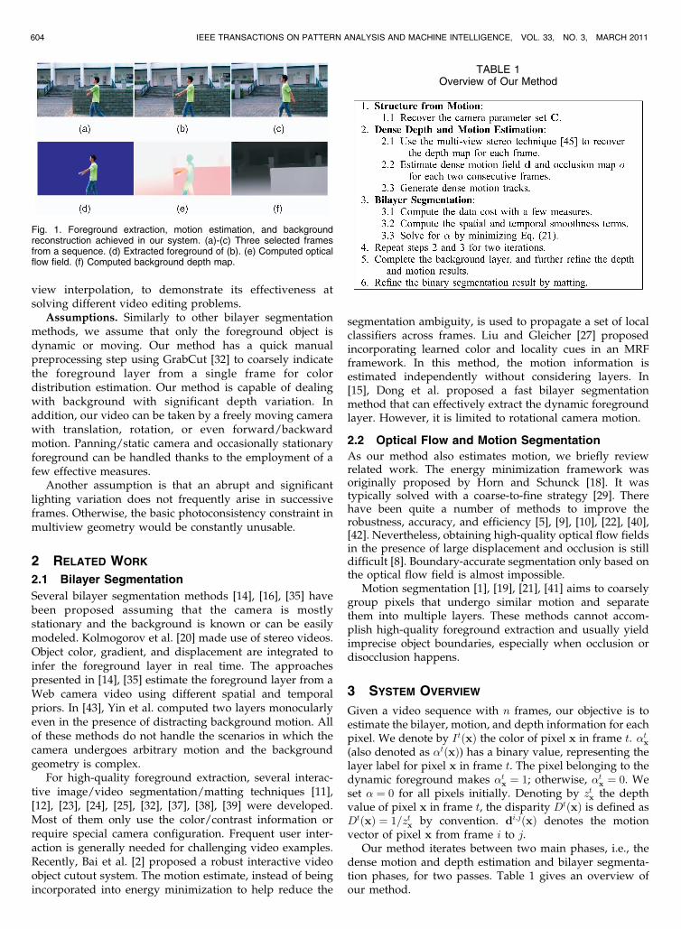
view interpolation, to demonstrate its effectiveness atsolving different video editing problems.
Assumptions. Similarly to other bilayer segmentationmethods, we assume that only the foreground object isdynamic or moving. Our method has a quick manualpreprocessing step using GrabCut [32] to coarsely indicatethe foreground layer from a single frame for colordistribution estimation. Our method is capable of dealingwith background with significant depth variation. Inaddition, our video can be taken by a freely moving camerawith translation, rotation, or even forward/backwardmotion. Panning/static camera and occasionally stationaryforeground can be handled thanks to the employment of afew effective measures.
Another assumption is that an abrupt and significantlighting variation does not frequently arise in successiveframes. Otherwise, the basic photoconsistency constraint inmultiview geometry would be constantly unusable.
2 RELATED WORK
2.1 Bilayer Segmentation
Several bilayer segmentation methods [14], [16], [35] havebeen proposed assuming that the camera is mostlystationary and the background is known or can be easilymodeled. Kolmogorov et al. [20] made use of stereo videos.Object color, gradient, and displacement are integrated toinfer the foreground layer in real time. The approachespresented in [14], [35] estimate the foreground layer from aWeb camera video using different spatial and temporalpriors. In [43], Yin et al. computed two layers monocularlyeven in the presence of distracting background motion. Allof these methods do not handle the scenarios in which thecamera undergoes arbitrary motion and the backgroundgeometry is complex.
For high-quality foreground extraction, several interac-tive image/video segmentation/matting techniques [11],[12], [23], [24], [25], [32], [37], [38], [39] were developed.Most of them only use the color/contrast information orrequire special camera configuration. Frequent user inter-action is generally needed for challenging video examples.Recently, Bai et al. [2] proposed a robust interactive videoobject cutout system. The motion estimate, instead of beingincorporated into energy minimization to help reduce the
segmentation ambiguity, is used to propagate a set of localclassifiers across frames. Liu and Gleicher [27] proposedincorporating learned color and locality cues in an MRFframework. In this method, the motion information isestimated independently without considering layers. In[15], Dong et al. proposed a fast bilayer segmentationmethod that can effectively extract the dynamic foregroundlayer. However, it is limited to rotational camera motion.
2.2 Optical Flow and Motion Segmentation
As our method also estimates motion, we briefly reviewrelated work. The energy minimization framework wasoriginally proposed by Horn and Schunck [18]. It wastypically solved with a coarse-to-fine strategy [29]. Therehave been quite a number of methods to improve therobustness, accuracy, and efficiency [5], [9], [10], [22], [40],[42]. Nevertheless, obtaining high-quality optical flow fieldsin the presence of large displacement and occlusion is stilldifficult [8]. Boundary-accurate segmentation only based onthe optical flow field is almost impossible.
Motion segmentation [1], [19], [21], [41] aims to coarselygroup pixels that undergo similar motion and separatethem into multiple layers. These methods cannot accom-plish high-quality foreground extraction and usually yieldimprecise object boundaries, especially when occlusion ordisocclusion happens.
3 SYSTEM OVERVIEW
Given a video sequence with n frames, our objective is toestimate the bilayer, motion, and depth information for eachpixel. We denote by ItðxÞ the color of pixel x in frame t. �tx(also denoted as �tðxÞ) has a binary value, representing thelayer label for pixel x in frame t. The pixel belonging to thedynamic foreground makes �tx ¼ 1; otherwise, �tx ¼ 0. Weset � ¼ 0 for all pixels initially. Denoting by ztx the depthvalue of pixel x in frame t, the disparity DtðxÞ is defined asDtðxÞ ¼ 1=ztx by convention. di;jðxÞ denotes the motionvector of pixel x from frame i to j.
Our method iterates between two main phases, i.e., thedense motion and depth estimation and bilayer segmenta-tion phases, for two passes. Table 1 gives an overview ofour method.
604 IEEE TRANSACTIONS ON PATTERN ANALYSIS AND MACHINE INTELLIGENCE, VOL. 33, NO. 3, MARCH 2011
TABLE 1Overview of Our Method
Fig. 1. Foreground extraction, motion estimation, and backgroundreconstruction achieved in our system. (a)-(c) Three selected framesfrom a sequence. (d) Extracted foreground of (b). (e) Computed opticalflow field. (f) Computed background depth map.

We start by using the structure from motion (SFM)
method of Zhang et al. [47] to recover the camera motion
parameters from the input video sequence. We apply the
SIFT algorithm [28], which produces a set of feature tracks
across frames, to estimate the camera poses. The feature
tracks on the dynamic foreground can automatically be
rejected according to the multiview geometry constraint
[17], leaving only background tracks for the camera motion
estimation. The output of SFM includes the recovered
camera parameter set C for all frames, and the 3D positions
of the background feature tracks. We denote by Ct ¼fKt;Rt;Ttg the camera parameters for frame t, where Kt is
the intrinsic matrix, Rt is the rotation matrix, and Tt is the
translation vector.With the recovered camera poses, we employ the multi-
view stereo method of Zhang et al. [45] to infer the view-
dependent dense depth maps for all frames. It is notable that
the dynamic foreground object does not satisfy the multi-
view geometry constraint and thus possibly does not receive
correct depth estimates, as demonstrated in Fig. 2. Contra-
rily, the background depth can be accurately computed even
without masking the foreground object out. This is because
the moving object is a type of “noise” in the depth
estimation, and can be effectively handled together with
image noise, occlusions, and estimation outliers. The
computed dense depth maps will be used in the latter
bilayer segmentation process.
4 DENSE MOTION ESTIMATION
We estimate motion for all pixels (Step 2 in Table 1) to
facilitate the following layer separation. The main differ-
ence between our method and traditional optical flow
estimation is that our method uses the layer information to
effectively handle occlusion and textureless regions. Note
that in [26], the layers need to be manually labeled
beforehand, while in our method the layer parameters can
be automatically computed and updated. We use the in-
plane displacement vector dt;tþ1ðxÞ (or dtþ1;tðxÞ) to denote
the motion of pixel x from frame t to tþ 1 (or from tþ 1 to
t). oðxÞ 2 f0; 1g labels occlusion. If the pixel x is occluded
when mapping from frame t to tþ 1, ot;tþ1ðxÞ ¼ 1; other-
wise ot;tþ1ðxÞ ¼ 0.
4.1 Initialization and Notations
To begin with, we partition each frame using the mean-shiftcolor segmentation method [13] and then perform thefollowing operations: 1) If a segment contains both fore-ground and background pixels (based on the current �estimate), it further splits. 2) A very small segment (withless than 10 pixels) will be merged to a neighboringsegment with the most similar mean color. When theseoperations are done, we represent the motion of a segmentbetween two images using a planar transformation. Let ltidenote the ith segment in frame t. For the pixel x 2 lti, itsdisplacement vector dt;tþ1ðxÞ is written as
dt;tþ1ðxÞ ¼ At;tþ1lti
�Ht;tþ1x� x; ð1Þ
where x is the homogenous coordinate of x and � is thescaling factor, i.e., the inverse of the third coordinate ofHt;tþ1x. Ht;tþ1 is a 3� 3 matrix, which represents the globalimage transformation caused by camera rotation or varyingfocal length. With the estimated camera parameters C,Ht;tþ1 is written as
Ht;tþ1 ¼ Ktþ1Rtþ1ðRtÞ>ðKtÞ�1: ð2Þ
�Ht;tþ1x is the rectified position of x after camera motioncompensation. Further, to describe the remaining motioncomponents, we use the general affine model At;tþ1
ltito
represent the transformation of a segment lti from image t totþ 1. It is a 2� 3 matrix and is expressed as
At;tþ1lti¼ a1ðltiÞ a2ðltiÞ b1ðltiÞ
a3ðltiÞ a4ðltiÞ b2ðltiÞ
� �;
where a1ðltiÞ, a2ðltiÞ, a3ðltiÞ, and a4ðltiÞ control rotation andscaling, and b1ðltiÞ and b2ðltiÞ are the translation components.
Equation (1) describes the parametrization of a displace-ment vector. In what follows, for simplicity’s sake, we stilldenote by d the motion vector. In the optimization process,all ds are substituted by the right-hand side expression of(1) and the variables to be optimized are actually the sixelements in A.
4.2 Objective Function
We define the following objective function to compute thedense displacement maps:
arg mind;o
Xn�1
t¼1
ðEt;tþ1ðd; oÞ þ Etþ1;tðd; oÞÞ; ð3Þ
whereEt;tþ1ðd; oÞ andEtþ1;tðd; oÞ are the bidirectional energyterms representing the mapping from frame t to tþ 1 and theother way around, respectively. Since they are similarlydefined, we only describe the construction of Et;tþ1ðd; oÞ.Et;tþ1ðd; oÞ consists of the color constancy, motion/
occlusion smoothness, and segmentation terms and isdefined as
Et;tþ1ðAt;tþ1; ot;tþ1Þ ¼Xx2It
mt;tþ1ðxÞ þX
y2NðxÞst;tþ1ðx;yÞ
24
35
þEt;tþ1r ðAt;tþ1Þ;
ð4Þ
ZHANG ET AL.: ROBUST BILAYER SEGMENTATION AND MOTION/DEPTH ESTIMATION WITH A HANDHELD CAMERA 605
Fig. 2. Depth recovery with dynamic objects. (a) Selected frames froman input video. (b) Recovered depth maps. Although the depth estimatesfor the dynamic foreground are problematic, they do not much affect thebackground depth estimation.

where Nð�Þ denotes the set of neighborhood. The threecomponents are, respectively: 1) the data matching termmt;tþ1ðxÞ, 2) the smoothness term st;tþ1ðx;yÞ that iscomprised of spatial motion smoothness and visibilityconsistency, and 3) a segmentation regularization term.
4.2.1 Data Term mðxÞ ¼ mIðxÞ þmSðxÞIt contains the color matching cost mIðxÞ and the shapematching cost mSðxÞ. mIðxÞ models color constancy withregard to possible occlusion and is given by
mt;tþ1I ðx;dt;tþ1ðxÞÞ
¼min
��t;tþ1d ðx;dt;tþ1ðxÞÞ; �d
�; ot;tþ1ðxÞ¼0; �tx ¼ �tþ1
x0 ;
min��t;tþ1d ðx;dt;tþ1ðxÞÞ; �o
�; ot;tþ1ðxÞ¼0; �tx 6¼ �tþ1
x0 ;
�o; ot;tþ1ðxÞ¼1;
8><>:
ð5Þ
where x0 ¼ xþ dt;tþ1ðxÞ, and �t;tþ1d ðx;dt;tþ1ðxÞÞ is a match-
ing function:
�t;tþ1d ðx;dt;tþ1ðxÞÞ ¼ kItþ1ðxþ dt;tþ1ðxÞÞ � ItðxÞk2:
�o in (5) is a penalty, preventing all pixels from being
labeled as occlusion [34]. �d is a truncated value larger than
�o to determine the upper limit of the cost. If ot;tþ1ðxÞ ¼ 0
and �tx 6¼ �tþ1xþdt;tþ1ðxÞ, there possibly exists occlusion.
On the other hand, we notice a foreground pixel x in
frame t should have its corresponding pixel x0 in frame
tþ 1 also in the foreground. We therefore define the shape
matching function as
mt;tþ1S ðxÞ ¼ ���tx
��tx � �tþ1
xþdt;tþ1ðxÞ�2; ð6Þ
where �� is a weight. �tx and ð�tx � �tþ1xþdt;tþ1ðxÞÞ
2 cause the
correspondence to be enforced only in the foreground layer.
This shape matching term significantly improves motion
estimation, especially for pixels with large displacement in
our experiments.
4.2.2 Smoothness Term sðx;yÞIt encourages motion and occlusion smoothness and isdefined as
st;tþ1ðx;yÞ ¼ �s�t;tþ1s ðx;yÞ þ �ojot;tþ1ðxÞ � ot;tþ1ðyÞj
þ �wjot;tþ1ðxÞ �Wt;tþ1ðxÞj;ð7Þ
where �s and jot;tþ1ðxÞ � ot;tþ1ðyÞj are the spatial smooth-ness constraints for displacement and occlusion. jot;tþ1ðxÞ �Wt;tþ1ðxÞj is the temporal constraint. All �s are weights. �sis a robust function written as
�t;tþ1s ðx;yÞ ¼
�1�
���tx � �ty����minfkdt;tþ1ðxÞ � dt;tþ1ðyÞk2; �sg;
which indicates that if two neighboring pixels belong todifferent layers after bilayer segmentation, the spatialsmoothness does not need to be preserved. �s controls themaximum cost.
In the last term jot;tþ1ðxÞ �Wt;tþ1ðxÞj, Wt;tþ1ðxÞ 2 f0; 1gis a precomputed binary value based on the displacement
dtþ1;t, indicating whether or not pixel x in It receives a
projection from Itþ1 based on the current dtþ1;t [34].
Wt;tþ1ðxÞ has value 1 if there is no corresponding pixel in
Itþ1 for ItðxÞ, implying x is likely to be occluded in Itþ1.
4.2.3 Segmentation Regularization
We express the segment regularization term Er as a
function of the elements of At;tþ1lti
. It is written as
Et;tþ1r ðAt;tþ1Þ ¼ �A
XKi¼1
��lti���ða1
�lti�� 1�2 þ a2
�lti�2
þ a3
�lti�2 þ
�a4ðlti
�� 1�2�
;
ð8Þ
where jltij denotes the number of pixels in lti,K is the segment
number in the frame t, and �A is a weight. Equation (8)
imposes a strong first-order intrasegment smoothness
constraint, which regularizes the affine parameters and
enforces translational motion. Because matching in ubiqui-
tous textureless regions is usually ill-posed, incorporating
this regularization term can avoid large affine distortion.
4.3 Solving the Energy Function
The energy defined in (4) is a complex one. We solve for a
dense displacement map with the consideration of occlusion
and segmentation. The occlusion variables in o are initially
set to zeros. Note that in the aforementioned SFM step, the
SIFT algorithm is used to obtain a set of sparse feature tracks
linking corresponding pixels among frames. They define a
set of features in each frame together with the displacement
vectors. We use these points to triangulate the frames, as
illustrated in Fig. 3a. Motion vectors of all pixels are
initialized using triangular interpolation in each triangle.
The matrix At;tþ1lti
for each segment lti is initialized with
a1ðltiÞ ¼ 1, a2ðltiÞ ¼ 0, a3ðltiÞ ¼ 0, and a4ðltiÞ ¼ 1. b1ðltiÞ and
b2ðltiÞ are initialized as the respective element values in the
mean motion vector for all pixels in segment lti.After initialization, the motion estimation method alter-
nates between the following two steps in a maximum of
three passes:
1. Fix o. Equation (7) is simplified to �s�t;tþ1s ðx;yÞ. We
solve for the six elements of At;tþ1lti
using the
Levenberg-Marquardt (LM) optimization. d is com-
puted using (1).
606 IEEE TRANSACTIONS ON PATTERN ANALYSIS AND MACHINE INTELLIGENCE, VOL. 33, NO. 3, MARCH 2011
Fig. 3. Motion initialization and interpolation. (a) We triangulate thetracked features and interpolate the in-plane displacement vectors for allpixels using the triangular interpolation. (b) An amplified region.

2. Fix d and update o by minimizing (4). Thesegmentation regularization term (8) and the term�s in (7) do not involve o and are thus omitted in thisstep. Each element in the occlusion map o has abinary label. We use graph cuts [6] to compute them.
Fig. 4 shows a motion estimation example. Figs. 4a and4b show two consecutive frames. To visualize the denseoptical flow, we adopt the color coding in [3], where thechromaticity is used to distinguish the motion direction andthe intensity corresponds to the motion magnitude, asshown in Fig. 4c. The computed optical flow and occlusionmaps using the above method are shown in Figs. 4d and 4e,respectively. Because, in the first place we have no layerinformation and set �s to all zeros, visual artifacts (due tosome segments spanning over different objects) are causedaround the object boundary.
The computed maps in Figs. 4d and 4e are used in thebilayer segmentation step thereupon (to be detailed inSection 5) to update the � map, where the result is shown inFig. 4f. In the second iteration (Step 4 in Table 1), weperform optical flow estimation again to refine motion andocclusion. The results are shown in Figs. 4g and 4h.
4.4 Dense Track Generation
After solving for the dense motion vectors, we link eachpixel forward and backward in the neighboring frames toeventually form dense motion tracks. They will facilitate thefollowing bilayer segmentation. To reduce the accumulatederror in this process, we limit the formed tracks (illustratedin Fig. 5) not longer than 20 frames. We also break a link inbetween pixels ItðxÞ and Itþ1ðx0Þ if any of the followingcriteria is triggered: 1) ot;tþ1ðxÞ ¼ 1 or otþ1;tðx0Þ ¼ 1; 2) theoptical flow consistency error
et;tþ1flow ðxÞ ¼ kd
t;tþ1ðxÞ þ dtþ1;tðx0Þk ð9Þ
is larger than 2 pixels. Here, x0 is the corresponding pixel ofx in frame tþ 1, i.e., x0 ¼ xþ dt;tþ1ðxÞ. We denote the
forward and backward half tracks as XF ¼ fxtjrt¼iþ1g and
XB ¼ fxtji�1t¼l g, respectively, for pixel x in frame i.
Further, with the recovered depth maps (detailed in
Section 3), we project each pixel to other frames to obtain
the corresponding X0F ¼ fx0tjrt¼iþ1g and X0B ¼ fx0tji�1t¼l g. If
pixel x refers to a static point, its depth estimate is usually
very accurate, and consequently, XF (or XB) should be near
to X0F (or X0B). Pixels on the dynamic object, on the
contrary, generally receive mistaken depth estimate, as
shown in Fig. 2. Also, to exclude the effect of occlusion,
which goes either forward or back, we compare two half
tracks, and select the pair with minimum difference to
measure the foreground/background confidence:
MtðxÞ ¼ minffðXF ;X0F Þ; fðXB;X0BÞg; ð10Þ
where fðXF ;X0F Þ ¼ maxt¼iþ1;...;rkxt � x0tk and fðXB;X0BÞ ¼maxt¼l;...;i�1kxt � x0tk. If MtðxÞ is large, it is likely that the
pixel x is in the foreground.MtðxÞ will be used to define a
confidence measure for bilayer segmentation.
5 BILAYER SEGMENTATION
The computed optical flow can help identify layers. But its
quality is not high enough to guarantee accurate foreground
extraction. We integrate other cues, such as color, contrast,
and depth, in our method to accomplish this goal.
ZHANG ET AL.: ROBUST BILAYER SEGMENTATION AND MOTION/DEPTH ESTIMATION WITH A HANDHELD CAMERA 607
Fig. 4. Optical flow estimation. (a)-(b) Frames 16 and 17. (c) A reference color wheel for motion coding. (d) Initial optical flow field d16;17. (e) Initialocclusion map o16;17. (f) Bilayer segmentation result �16 in the second iteration. (g) Updated optical flow field with the � map shown in (f). (h) Refinedocclusion map. (i) Close-up of (d). (j) Close-up of (g).
Fig. 5. Optical flow track illustration in multiple frames.

5.1 Data Term
With the computed depth maps (described in Section 3), the3D warping technique [30] can be used to render new viewsby projecting pixels from one frame to other. In our method,we warp the neighboring 2l frames, i.e., fIt�l; . . . ; Itþlg toframe t using the depth information. We reiterate that wedo not assume all pixels have correct depths. Instead, ourmethod collects depth statistics, using multiple frames tomitigate the influence of mistakes in the layer computation.
Warping neighboring frames to the present one allowsusing multiple cues. We employ the background subtrac-tion, local color statistics, and depth/motion consistencymeasures (denoted by Lc, Lg, and Lm, respectively), whoseconstruction will be detailed later in this section. It is notablethat these measures evaluate layer separation from differentangles and thus are similarly important for producing thefinal result. It is also unknown in advance which one is morereliable for a specific example. In our method, we adopt asimple and yet very effective voting-like scheme to combinethese measures and express the data cost as
Ed��tx�¼ median
�Lc��tx�; Lg��tx�; Lm
��tx��; ð11Þ
where �tx is the foreground label for pixel x in frame t. Thedata term favors the majority of the measures. It is robust tooutliers because each measure does not directly affect thefinal result. An occasional degradation of one term does notmatter as much as using a weighted sum scheme.
During warping, we exclude foreground-layer pixels,where �tx is labeled 1 in the previous iteration. Initially,since all �s are set to zeros, we alternatively exclude pixelsfor which MtðxÞ is larger than a threshold. The image anddisparity map warped from It
0to It are denoted as It
0;t andDt0;t respectively. Fig. 6 shows an example. The red pixelsare those receiving no projection during the warping. Wenow describe the three measures.
5.1.1 Background Subtraction Measure
With the inevitable estimation error, the warped points maydeviate from their correct positions. We thus apply the
following method to locally search the best match. Theappearance consistency error for x with respect to It andIt0;t is given by
At0;tðxÞ ¼ 1
jW jminx0
Xy2WkItðxþ yÞ � It0;tðx0 þ yÞk; ð12Þ
where W is a 3� 3 window for block matching and x0 is inthe neighborhood region of x, where kx0 � xk � r, asillustrated in Fig. 7. In our experiments, r ¼ 2 (pixels).
In addition to warping color images, we also constructthe warped disparity map Dt0;t and define the disparityconsistency error as the blockwise minimum differencebetween pixels. It is given by
Dt0;tðxÞ ¼ 1
jW jminx0
Xy2WjDtðxþ yÞ � Dt0;tðx0 þ yÞj : ð13Þ
This disparity consistency error will be used in defining thedepth/motion consistency measure.
After block matching, we gather a set of At0;tðxÞ for eachpixel x in frame t with respect to different ts as we havewarped multiple frames to frame t. Their statistics reflectthe chance that one pixel receives the correct depthestimate. For instance, if the residual error At0;tðxÞ isconsistently large for multiple ts, it is quite possible thatpixel x will be in the dynamic foreground layer or beoccluded in most frames. To abstract this type of informa-tion, for each x, we apply the median filter to all At0;tðxÞs,where t0 ¼ t� l; . . . ; tþ l, which yields
AtðxÞ ¼ medianfAt�l;tðxÞ; . . . ;Atþl;tðxÞg: ð14Þ
A large median value AtðxÞ implies that the color of pixel xin the present frame is quite different from the majority ofthe warped background color. So, pixel x is very likely to bein foreground.
Similarly, we compute the median value of the disparityconsistency errors
DtðxÞ ¼ medianfDt�l;tðxÞ; . . . ;Dtþl;tðxÞg: ð15Þ
DtðxÞ will be used in defining the depth/motion consis-tency measure Lm.
Finally, we express the layer likelihood based on thebackground subtraction measure as
608 IEEE TRANSACTIONS ON PATTERN ANALYSIS AND MACHINE INTELLIGENCE, VOL. 33, NO. 3, MARCH 2011
Fig. 6. 3D warping. The neighboring frames are warped to It. The redpixels are those receiving no projection during the warping process.
Fig. 7. Local block matching. The warped pixel x in It0 ;t may slightly
deviate from its correct position. We perform local search to reduceerror. The red solid rectangle is the matching windows W , and the bluedashed circle indicates the search region.

Lcð�tx ¼ 0Þ ¼ AtðxÞAtðxÞ þ �c
;
Lcð�tx ¼ 1Þ ¼ �c
AtðxÞ þ �c;
ð16Þ
where �c ¼ 5 � 13 in our experiments, controlling the
labeling threshold. AtðxÞ > �c yields Lcð�tx ¼ 0Þ > 0:5 >
Lcð�tx ¼ 1Þ, indicating that x is likely a dynamic foreground
pixel.This measure is sometimes error-prone if the foreground
and background pixels have similar colors. To overcome it,
in this system, other statistics models are also employed.
5.1.2 Local Color Statistics Measure
Previous bilayer segmentation methods [25], [32], [37]
employ the Gaussian mixture model (GMM) to describe
color. The typical scheme is to sample color and build two
global GMMs for background and foreground, respectively.
In our method, as we process general videos in which the
background image varies over time, building a global
background GMM is not appropriate. Here, we construct
them separately for each frame.With the set of warped images for each frame t, as shown
in Fig. 6, we stack them and apply median filtering to each
pixel to approximate the background image Bt, as shown in
Fig. 8b. Background regions that are consistently occluded
in the whole sequence find no color information (shown in
red in Fig. 8b). We apply a simple completion method [31]
to infer them, as shown in Fig. 8c. Then, the Mean Shift
algorithm [13] is employed to segment Bt (Fig. 8d) followed
by using a Gaussian distribution Nð�bk;�bkÞ to model the
color in each segment Sk. Directly propagating the
estimated background color models into the missing areas
for completion is also a choice. Note that background
completion may produce error. It is, however, not influen-
tial because we only use the statistical color model but not
the respective pixel values. Moreover, as we remove the
foreground estimate in 3D warping, occasional error isquickly eliminated in iterations.
With the background color models, for each pixel, wesearch the distributions that it possibly belongs to in a localarea, as shown in Figs. 8d and 8e. The background colorprobability is written as
pð�tx ¼ 0Þ ¼ maxl
j¼1N�ItðxÞ
���bmj;�b
mj
�; ð17Þ
where l is the number of the background samples in thelocal window (Fig. 8e) and mj indexes the correspondingGaussian cluster for each sample.
The foreground color model construction is easier. Wecompute from a single frame the foreground region, as shownin Fig. 8f, using GrabCut [32]. Based on it, we construct theforeground color GMM with Gaussian distributionsfNð�f1 ;�
f2Þ; Nð�
f2 ;�
f2Þ; . . . Nð�fKf
;�fKfÞg. The probability that
one pixel belongs to the foreground layer is accordinglyexpressed as
pð�tx ¼ 1Þ ¼XKf
k¼1
wfkN�Itx���fk;�f
k
�; ð18Þ
where wfk is the computed weight corresponding to thekth component of the GMM and Kf is the total number ofthe clusters. The definition difference between (17) and (18)is due to the use of local and global color models.
Finally, the local color statistics measure is defined as:
Lgð�txÞ ¼log pð�txÞ
log pð�tx ¼ 0Þ þ log pð�tx ¼ 1Þ ; ð19Þ
where the denominator is for normalization. Fig. 8g showsthe local color statistics measure map. A large value reflectshigh confidence that a pixel belongs to the foreground layer.Our model is different from the one in [15] because we donot assume rotational camera motion. There also does notexist a panoramic background image that can be estimatedbeforehand.
5.1.3 Depth/Motion Consistency Measure
Depth/motion information is also essential in our methodfor identifying foreground pixels. We combine disparityconsistency error D, which is defined in (13) and (15), withthe motion consistency errorM, described in Section 4.4, toexpress another likelihood:
Lmð�tx ¼ 0Þ ¼ maxMtðxÞ
MtðxÞ þ �m;DtðxÞ
DtðxÞ þ �d
( );
Lmð�tx ¼ 1Þ ¼ 1� Ltm��tx ¼ 0
�:
ð20Þ
Here, �d and �m are two thresholds and are set to 0:2ðDmax �DminÞ and 8 � 10, respectively, where ½Dmin; Dmax� is theapproximated disparity range of the scene. Equation (20)implies that only when both D and M are small are weconfident that the pixel is in the background layer.
5.2 Smoothness Terms
With the data cost defined in (11), we optimize thefollowing function with the consideration of the spatialand temporal smoothness:
ZHANG ET AL.: ROBUST BILAYER SEGMENTATION AND MOTION/DEPTH ESTIMATION WITH A HANDHELD CAMERA 609
Fig. 8. Warped color statistics. (a) One frame from a sequence.(b) Estimated background image by warping 30 neighboring frames to(a). The red pixels do not receive projection. (c) Completed backgroundimage by inpainting. (d) Segmented background image by Mean Shift.(e) The color in each segment is modeled by a Gaussian distribution.Three segments are included in the local region centered at x. (f) Initialforeground layer for GMM training. (g) The confidence map of the localcolor statistics.

EBð�Þ ¼Xnt¼1
Xx2ItðEd
��tx�þ �S
Xy2NðxÞ
Es
��tx; �
ty
�þ �T G
��tx��;
ð21Þ
where Esð�tx; �tyÞ and Gð�txÞ are the spatial and temporalsmoothness terms, respectively, which are described asfollows: �S and �T are weights.
5.2.1 Spatial Smoothness
Strong edges of the background image could mistake thebilayer segmentation. We attenuate them when enforcingthe spatial smoothness.
When computing the appearance consistency error At
using median filtering, it at the same time finds the matched
pixel for x from a warped image. Suppose it is pixel x� in
It�;t. We denote by gt
�;tðx�Þ and gtðxÞ the corresponding
gradients in It�;t and It, respectively. We set gt
�;tðx�Þ ¼ 0 if it
cannot be computed due to the lack of the matched pixel
after warping. Then, we define the following function,
which is similar to the one in [35], to attenuate the
background contrast:
dtaðxÞ ¼ kgtðxÞk2 � 1� e�
AtðxÞ2
2�5�5
1þ� gt� ;tðx�Þ
5
�2e�AtðxÞ2
2�10�10
:
It means if AtðxÞ is small, it is quite possible that pixel x isin the background layer, and thus, the contrast should beattenuated more significantly.
Finally, the spatial smoothness term is written as
Es
��tx; �
ty
�¼���tx � �ty�� � exp
�� �dtaðx;yÞ
�; ð22Þ
where x and y are neighboring pixels, and � is a robustparameter that weights the color contrast. It is set to
ð2hkIx � Iyk2iÞ�1, where h�i denotes the expectation opera-tor, same as the one defined in [35]. Esð�x; �yÞ indicates thatif both x and y are in the foreground (or background) layer,Es has zero value. Otherwise, the smoothness strength isadaptively adjusted according to the color contrast.
5.2.2 Temporal Consistency
This term is defined bidirectionally as
G��tx�¼ Gt;tþ1
��tx�þ Gt;t�1
��tx�: ð23Þ
Let pixel x0 in Itþ1 be the corresponding one of x in It
according to the estimated motion vector. Gt;tþ1ð�txÞ isexpressed as
Gt;tþ1��tx�¼���tx � �tþ1
x0
�� � wt;tþ1flow ðxÞ;
where j�tx � �tþ1x0 j ¼ 1 if the � labels are different. Or else, no
temporal smoothness penalty will be enforced. wt;tþ1flow ðxÞ
penalizes the label inconsistency based on the measure offorward and backward optical flow (9) and the pixel colordifference. It is given by
wt;tþ1flow ðxÞ ¼ exp �kd
t;tþ1ðxÞ þ dtþ1;tðx0Þk2
�2flow
!�
exp �kItðxÞ � Itþ1ðx0Þk2
�2color
!;
ð24Þ
610 IEEE TRANSACTIONS ON PATTERN ANALYSIS AND MACHINE INTELLIGENCE, VOL. 33, NO. 3, MARCH 2011
TABLE 2The Statistics of the Tested Sequences
TABLE 3The Parameters
Fig. 10. All coarse foreground regions used in the examples listed inTable 2. They are used in the foreground color modeling (Section 5.1).
Fig. 9. Removing foreground outliers. (a) One video frame. (b) Thecomputed foreground mask that contains a few isolated regions. Thesmall ones are outliers. (c) The extracted foreground layer.

where �flow ¼ 1:4 and �color ¼ 15. Gt;t�1ð�txÞ is definedsimilarly.
5.3 Overall Computation
In the bilayer segmentation step, to reduce the complexityin computing the data cost for each frame, we only select20-30 frames, with the interval of 5 frames between each, toperform 3D warping. The minimum interval between thereference frame and sampling frames is generally set to10 � 20. After the data and smoothness terms are computed,we apply graph cuts to compute the � maps by minimizingEBð�Þ. Each time we solve for 10 maps sequentially.
Due to inevitable estimation error and image noise, theextracted foreground may contain multiple isolated regions,as shown in Fig. 9b. Most of them are small outliers.Therefore, suppose there are m moving objects, we firstselect n (n � m) largest segments, each containing at least400 pixels. Then, we further select the segments from theremaining ones (containing at least 400 pixels), whosesmallest distance to these n segments is less than athreshold. This simple strategy works well empirically.
After computing � in the first pass, we go back to Step 2in Table 1 and further refine the motion and depth maps asdescribed in Section 4. Two overall passes are sufficient toachieve high-quality bilayer segmentation.
The final step is to recompute the background imagesand the depth maps based on the � estimate using themethod of Bhat et al. [4] (Step 5 in Table 1). We also updatethe motion vectors for the background pixels in accordancewith the pixel correspondences established using the depthinformation. It is found that the depth computed with themultiview geometry constraint is in general more accuratethan the optical flow estimate. We will show in Fig. 12mhow the final refinement is useful.
An optional function is provided in our system to refinethe foreground boundary by matting [2] such that theextracted layers are usable in other video compositionapplications.
6 EXPERIMENTAL RESULTS
We experimented with several challenging exampleswhere the videos2 are taken by a handheld camera andstrong vibration exists. Table 2 lists the number of framesand resolutions.
In our implementation, the optical flow is estimated inthe grayscale channel (the scale range is ½0; 255�). Appear-ance consistency error (12) uses the YUV color space. Othercomputation is performed in the RGB color space. Ourexperiments are conducted on a desktop PC with a 4-coreXeon 2.0 GHz CPU. The parameter setting is easy, as shownin Table 3 and described in Section 5.
Fig. 10 contains the computed foreground regions for theforeground color distribution modeling in all examples(described in Section 5.1). Each sequence uses only one suchregion, which can be quickly obtained by GrabCut [32]. Theresults do not need to be very accurate for the purpose ofcolor distribution computation.
The processing time depends on the number of framesand image resolution. For a sequence with resolution 720�576 (pixels), the depth estimation (Step 2.1 of Table 1) in thefirst iteration spends 3 minutes for each frame. In the seconditeration, depth refinement runs much faster (a few secondsfor each frame) because only depths around the foregroundboundaries need to be updated. In each iteration, the motionestimation (Step 2.2 of Table 1) uses 1 minute on average toprocess one frame. The computation time for bilayersegmentation is about 30 seconds per frame, where over95 percent of it is spent on the data cost computation.
6.1 Workthrough Example
We use the example shown in Fig. 11 to illustrate how ourmethod works. In the first iteration, the estimated appearanceconsistency error map A and the disparity consistency error
ZHANG ET AL.: ROBUST BILAYER SEGMENTATION AND MOTION/DEPTH ESTIMATION WITH A HANDHELD CAMERA 611
Fig. 11. Bilayer segmentation. (a) One video frame. (b) The appearance consistency map A. (c) The disparity consistency map D. (d) The trackconsistency map M. (e) The likelihood Lg with the local color statistics model. (f) The computed data costs for all pixels. (g) The backgroundattenuation map. (h) The extracted foreground image.
2. The supplemental video can be found at http://www.cad.zju.edu.cn/home/gfzhang/projects/segmentation/motioncut/.
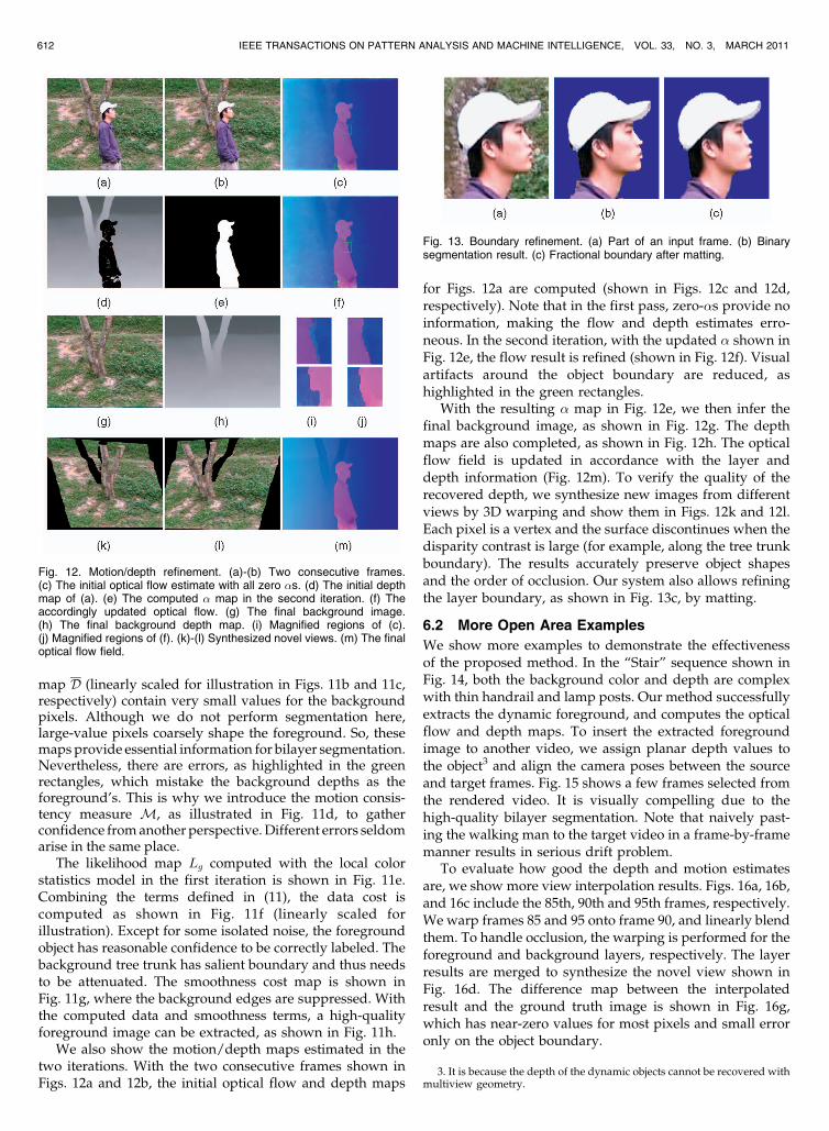
map D (linearly scaled for illustration in Figs. 11b and 11c,respectively) contain very small values for the backgroundpixels. Although we do not perform segmentation here,large-value pixels coarsely shape the foreground. So, thesemaps provide essential information for bilayer segmentation.Nevertheless, there are errors, as highlighted in the greenrectangles, which mistake the background depths as theforeground’s. This is why we introduce the motion consis-tency measure M, as illustrated in Fig. 11d, to gatherconfidence from another perspective. Different errors seldomarise in the same place.
The likelihood map Lg computed with the local colorstatistics model in the first iteration is shown in Fig. 11e.Combining the terms defined in (11), the data cost iscomputed as shown in Fig. 11f (linearly scaled forillustration). Except for some isolated noise, the foregroundobject has reasonable confidence to be correctly labeled. Thebackground tree trunk has salient boundary and thus needsto be attenuated. The smoothness cost map is shown inFig. 11g, where the background edges are suppressed. Withthe computed data and smoothness terms, a high-qualityforeground image can be extracted, as shown in Fig. 11h.
We also show the motion/depth maps estimated in thetwo iterations. With the two consecutive frames shown inFigs. 12a and 12b, the initial optical flow and depth maps
for Figs. 12a are computed (shown in Figs. 12c and 12d,respectively). Note that in the first pass, zero-�s provide noinformation, making the flow and depth estimates erro-neous. In the second iteration, with the updated � shown inFig. 12e, the flow result is refined (shown in Fig. 12f). Visualartifacts around the object boundary are reduced, ashighlighted in the green rectangles.
With the resulting � map in Fig. 12e, we then infer thefinal background image, as shown in Fig. 12g. The depthmaps are also completed, as shown in Fig. 12h. The opticalflow field is updated in accordance with the layer anddepth information (Fig. 12m). To verify the quality of therecovered depth, we synthesize new images from differentviews by 3D warping and show them in Figs. 12k and 12l.Each pixel is a vertex and the surface discontinues when thedisparity contrast is large (for example, along the tree trunkboundary). The results accurately preserve object shapesand the order of occlusion. Our system also allows refiningthe layer boundary, as shown in Fig. 13c, by matting.
6.2 More Open Area Examples
We show more examples to demonstrate the effectivenessof the proposed method. In the “Stair” sequence shown inFig. 14, both the background color and depth are complexwith thin handrail and lamp posts. Our method successfullyextracts the dynamic foreground, and computes the opticalflow and depth maps. To insert the extracted foregroundimage to another video, we assign planar depth values tothe object3 and align the camera poses between the sourceand target frames. Fig. 15 shows a few frames selected fromthe rendered video. It is visually compelling due to thehigh-quality bilayer segmentation. Note that naively past-ing the walking man to the target video in a frame-by-framemanner results in serious drift problem.
To evaluate how good the depth and motion estimatesare, we show more view interpolation results. Figs. 16a, 16b,and 16c include the 85th, 90th and 95th frames, respectively.We warp frames 85 and 95 onto frame 90, and linearly blendthem. To handle occlusion, the warping is performed for theforeground and background layers, respectively. The layerresults are merged to synthesize the novel view shown inFig. 16d. The difference map between the interpolatedresult and the ground truth image is shown in Fig. 16g,which has near-zero values for most pixels and small erroronly on the object boundary.
612 IEEE TRANSACTIONS ON PATTERN ANALYSIS AND MACHINE INTELLIGENCE, VOL. 33, NO. 3, MARCH 2011
Fig. 13. Boundary refinement. (a) Part of an input frame. (b) Binarysegmentation result. (c) Fractional boundary after matting.
Fig. 12. Motion/depth refinement. (a)-(b) Two consecutive frames.(c) The initial optical flow estimate with all zero �s. (d) The initial depthmap of (a). (e) The computed � map in the second iteration. (f) Theaccordingly updated optical flow. (g) The final background image.(h) The final background depth map. (i) Magnified regions of (c).(j) Magnified regions of (f). (k)-(l) Synthesized novel views. (m) The finaloptical flow field.
3. It is because the depth of the dynamic objects cannot be recovered withmultiview geometry.

With the estimated depth and motion, we produce the“slow shot” visual effect, which “densifies” the video bysynthesizing frames in between originally consecutive ones.In our experiments, in between any two frames t and tþ 1,we insert four or nine more frames by view interpolation.Please refer to our supplemental video, which can be foundat http://www.cad.zju.edu.cn/home/gfzhang/projects/segmentation/motioncut/, for the complete sequences andmore examples.
6.3 Indoor Example
To further demonstrate the robustness of the proposedmethod, we use a Web camera (Logitech Quick-CamPro 9000) to capture an indoor sequence (shown inFig. 17) in low light. This sequence contains strongnoise and luminance variation among frames. Inaddition, most of the regions are textureless, which isvery challenging for the motion and depth estimation.Our method is robust to these problems. The completeresult is included in our supplementary video, which
can be found at http://www.cad.zju.edu.cn/home/gfzhang/ projects/segmentation/motioncut/.
7 SPECIAL CASE DISCUSSION
We show a few examples that are generally regarded as
special and challenging in bilayer segmentation and
provide more discussion in this section.
7.1 Rotational Camera Motion
The first type of example we discuss is those captured by
static or rotating-only cameras. In this case, the depth
cannot be recovered due to the lack of the multiview stereo
constraint. Our system, however, still works because view
warping and background estimation can be relied on to
solve for bilayer segmentation. No change is needed in our
system except for constant depth initialization for all pixels
such that the depth consistency measure in (20) does not
really function.We show in Fig. 18 a video example taken by a rotating
camera (the complete sequence included in the supplemental
video, which can be found at http://www.cad. zju.edu.cn/
home/gfzhang/projects/segmentation/motioncut/). Con-
stant depth is used. The computed foreground image and
ZHANG ET AL.: ROBUST BILAYER SEGMENTATION AND MOTION/DEPTH ESTIMATION WITH A HANDHELD CAMERA 613
Fig. 14. “Stair” example. (a) One input frame. (b) The extracted foreground image. (c) The computed optical flow map. (d) The estimated backgroundimage. (e) The recovered background depth map.
Fig. 16. View interpolation. (a)-(c) Frames 85, 90, and 95 of the “Stair”sequence. (d) Interpolated frame 90, using the motion and depthinformation of frames 85 and 95. The absolutely black pixels are themissing ones. (e) Close-up of (b). (f) Close-up of (d). (g) Differenceimage of (e) and (f).
Fig. 15. Inserting the extracted foreground layer into another video.
Fig. 17. An indoor example. (a) Original frames. (b) Extractedforeground images. (c) Optical flow fields. (d) Background depth maps.
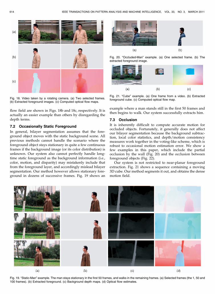
flow field are shown in Figs. 18b and 18c, respectively. It isactually an easier example than others by disregarding thedepth terms.
7.2 Occasionally Static Foreground
In general, bilayer segmentation assumes that the fore-ground object moves with the static background scene. Allprevious methods cannot handle the scenario where theforeground object stays stationary in quite a few continuousframes if the background image (or its color distribution) isunknown. Our system also cannot perfectly handle long-time static foreground as the background information (i.e.,color, motion, and disparity) may mistakenly include thatfrom the foreground layer, and accordingly mislead bilayersegmentation. Our method however allows stationary fore-ground in dozens of successive frames. Fig. 19 shows an
example where a man stands still in the first 50 frames andthen begins to walk. Our system successfully extracts him.
7.3 Occlusion
It is inherently difficult to compute accurate motion foroccluded objects. Fortunately, it generally does not affectour bilayer segmentation because the background subtrac-tion, local color statistics, and depth/motion consistencymeasures work together in the voting-like scheme, which isrobust to occasional motion estimation error. We show afew examples in this paper, which include the partialocclusion by the wall (Fig. 20) and the occlusion betweenforeground objects (Fig. 22).
Our system is not restricted to near-planar foregroundextraction. Fig. 21 shows a sequence containing a moving3D cube. Our method segments it out, and obtains the densemotion field.
614 IEEE TRANSACTIONS ON PATTERN ANALYSIS AND MACHINE INTELLIGENCE, VOL. 33, NO. 3, MARCH 2011
Fig. 18. Video taken by a rotating camera. (a) Two selected frames.(b) Extracted foreground images. (c) Computed optical flow maps.
Fig. 19. “Static-Man” example. The man stays stationary in the first 50 frames, and walks in the remaining frames. (a) Selected frames (the 1, 50 and100 frames). (b) Extracted foreground. (c) Background depth maps. (d) Optical flow estimates.
Fig. 20. “Occluded-Man” example. (a) One selected frame. (b) Theextracted foreground image.
Fig. 21. “Cube” example. (a) One frame from a video. (b) Extractedforeground cube. (c) Computed optical flow map.

7.4 Multiple Foreground Objects
Although our system is mainly developed for extractingone foreground object, it can be employed to handlemultiple moving objects with the procedure described inSection 5.3. Fig. 22 shows an example that contains twopersons at different depths. Our extracted foregroundimages are shown in Figs. 22c and 22d. Note that if thereare many foreground objects with small sizes, it will bedifficult for our system to distinguish them from outliers.
7.5 Limitations
The current system still has the following limitations: First, ifthe background layer does not have sufficient features or isextremely textureless, the camera parameters and motion/depth estimation could be difficult. Second, our systemassumes the background is static to satisfy the photoconsis-tency constraint. Pixels with significant appearance changedue to illumination variation, reflection, or shadow will berecognized as foreground accordingly. Fig. 23 shows anexample where the sequence contains a walking person withhis shadow on the ground. Our method classifies theshadow as part of the foreground layer. Similarly, unmovingobjects will be regarded as background. An example is thestatic person in Fig. 24. Only his waving arm is segmentedinto the foreground layer.
8 CONCLUSION AND FUTURE WORK
In this paper, we have proposed a complete system for high-quality bilayer segmentation, and motion and depthestimation from videos taken by a handheld camera. Our
method alternates between two major steps. In the first one,we estimate the camera motion parameters, the optical flowfields, and the depth maps. The visibility, segmentation, andlayer information is encoded for handling occlusionand textureless regions. In the second step, we take depthand motion into layer separation. We have proposed asimple voting-like scheme to reliably detect the movingobjects. A few postprocessing steps finally compute themotion fields and the background color/depth images.
Presently, our system assumes static background andidentifies dynamic regions as foreground. The bilayersegmentation cannot separate multiple moving layers. Partof our future work will be along this line to accomplishrobust multilayer segmentation with regard to morediversified occlusion and color constraints.
ACKNOWLEDGMENTS
The authors would like to thank the associate editor and allof the reviewers for their constructive comments to improvethe manuscript. This work is supported by the 973 programof China (No. 2009CB320804), NSF of China (Nos. 60633070and 60903135), and a grant from the Research GrantsCouncil of the Hong Kong Special Administrative Region(Project No. 412708).
REFERENCES
[1] S. Ayer and H.S. Sawhney, “Layered Representation of MotionVideo Using Robust Maximum-Likelihood Estimation of MixtureModels and Mdl Encoding,” Proc. IEEE Int’l Conf. Computer Vision,pp. 777-784, 1995.
ZHANG ET AL.: ROBUST BILAYER SEGMENTATION AND MOTION/DEPTH ESTIMATION WITH A HANDHELD CAMERA 615
Fig. 22. “Two-Men” example. (a)-(b) Two selected frames. (c)-(d) Extracted foreground images.
Fig. 23. “Shadow” example. (a)-(b) Selected frames. (c)-(d) The extracted foreground images. The shadow is recognized as part of the foreground.
Fig. 24. “Waving-Arm” example. (a)-(b) Selected frames. (c)-(d) The extracted foreground images. The static body, but not the waving arm, issegmented into the background layer.

[2] X. Bai, J. Wang, D. Simons, and G. Saprio, “Video Snapcut: RobustVideo Object Cutout Using Localized Classifiers,” ACM Trans.Graphics, vol. 28, no. 3, 2009.
[3] S. Baker, D. Scharstein, J.P. Lewis, S. Roth, M.J. Black, and R.Szeliski, “A Database and Evaluation Methodology for OpticalFlow,” Proc. IEEE Int’l Conf. Computer Vision, pp. 1-8, 2007.
[4] P. Bhat, C.L. Zitnick, N. Snavely, A. Agarwala, M. Agrawala, B.Curless, M. Cohen, and S.B. Kang, “Using Photographs toEnhance Videos of a Static Scene,” Rendering Techniques 2007,J. Kautz and S. Pattanaik, eds., pp. 327-338, A.K. Peters, June 2007.
[5] M.J. Black and P. Anandan, “The Robust Estimation of MultipleMotions: Parametric and Piecewise-Smooth Flow Fields,” Compu-ter Vision and Image Understanding, vol. 63, no. 1, pp. 75-104, 1996.
[6] Y. Boykov, O. Veksler, and R. Zabih, “Fast Approximate EnergyMinimization via Graph Cuts,” IEEE Trans. Pattern Analysis andMachine Intelligence, vol. 23, no. 11, pp. 1222-1239, Nov. 2001.
[7] M. Brown and D.G. Lowe, “Recognising Panoramas,” Proc. IEEEInt’l Conf. Computer Vision, pp. 1218-1227, 2003.
[8] T. Brox, C. Bregler, and J. Malik, “Large Displacement OpticalFlow,” Proc. IEEE CS Conf. Computer Vision and Pattern Recognition,2009.
[9] T. Brox, A. Bruhn, N. Papenberg, and J. Weickert, “High AccuracyOptical Flow Estimation Based on a Theory for Warping,” Proc.European Conf. Computer Vision, vol. 4, pp. 25-36, 2004.
[10] A. Bruhn and J. Weickert, “Towards Ultimate Motion Estimation:Combining Highest Accuracy with Real-Time Performance,” Proc.IEEE Int’l Conf. Computer Vision, pp. 749-755, 2005.
[11] Y.-Y. Chuang, A. Agarwala, B. Curless, D. Salesin, and R. Szeliski,“Video Matting of Complex Scenes,” ACM Trans. Graphics, vol. 21,no. 3, pp. 243-248, 2002.
[12] Y.-Y. Chuang, B. Curless, D. Salesin, and R. Szeliski, “A BayesianApproach to Digital Matting,” Proc. IEEE CS Conf. Computer Visionand Pattern Recognition, vol. 2, pp. 264-271, 2001.
[13] D. Comaniciu and P. Meer, “Mean Shift: A Robust ApproachToward Feature Space Analysis,” IEEE Trans. Pattern Analysis andMachine Intelligence, vol. 24, no. 5, pp. 603-619, May 2002.
[14] A. Criminisi, G. Cross, A. Blake, and V. Kolmogorov, “BilayerSegmentation of Live Video,” Proc. IEEE CS Conf. Computer Visionand Pattern Recognition, vol. 1, pp. 53-60, 2006.
[15] Z. Dong, L. Jiang, G. Zhang, Q. Wang, and H. Bao, “Live VideoMontage with a Rotating Camera,” Computer Graphics Forum,vol. 28, no. 7, pp. 1745-1753, 2009.
[16] A.M. Elgammal, D. Harwood, and L.S. Davis, “Non-ParametricModel for Background Subtraction,” Proc. European Conf. ComputerVision, vol. 2, pp. 751-767, 2000.
[17] R.I. Hartley and A. Zisserman, Multiple View Geometry in ComputerVision, second ed. Cambridge Univ. Press, 2004.
[18] B.K.P. Horn and B.G. Schunck, “Determining Optical Flow,”Artificial Intelligence, vol. 17, nos. 1-3, pp. 185-203, 1981.
[19] S. Khan and M. Shah, “Object Based Segmentation of Video UsingColor, Motion and Spatial Information,” Proc. IEEE CS Conf.Computer Vision and Pattern Recognition, vol. 2, pp. 746-751, 2001.
[20] V. Kolmogorov, A. Criminisi, A. Blake, G. Cross, and C. Rother,“Bi-Layer Segmentation of Binocular Stereo Video,” Proc. IEEE CSConf. Computer Vision and Pattern Recognition, vol. 2, pp. 407-414,2005.
[21] M.P. Kumar, P.H.S. Torr, and A. Zisserman, “Learning LayeredMotion Segmentation of Video,” Proc. IEEE Int’l Conf. ComputerVision, pp. 33-40, 2005.
[22] V.S. Lempitsky, S. Roth, and C. Rother, “Fusionflow: Discrete-Continuous Optimization for Optical Flow Estimation,” Proc. IEEECS Conf. Computer Vision and Pattern Recognition, 2008.
[23] A. Levin, D. Lischinski, and Y. Weiss, “A Closed-Form Solution toNatural Image Matting,” IEEE Trans. Pattern Analysis and MachineIntelligence, vol. 30, no. 2, pp. 228-242, Feb. 2008.
[24] Y. Li, J. Sun, and H.-Y. Shum, “Video Object Cut and Paste,” ACMTrans. Graphics, vol. 24, no. 3, pp. 595-600, 2005.
[25] Y. Li, J. Sun, C.-K. Tang, and H.-Y. Shum, “Lazy Snapping,” ACMTrans. Graphics, vol. 23, no. 3, pp. 303-308, 2004.
[26] C. Liu, W.T. Freeman, E.H. Adelson, and Y. Weiss, “Human-Assisted Motion Annotation,” Proc. IEEE CS Conf. Computer Visionand Pattern Recognition, 2008.
[27] F. Liu and M. Gleicher, “Learning Color and Locality Cues forMoving Object Detection and Segmentation,” Proc. IEEE CS Conf.Computer Vision and Pattern Recognition, 2009.
[28] D.G. Lowe, “Distinctive Image Features from Scale-InvariantKeypoints,” Int’l J. Computer Vision, vol. 60, no. 2, pp. 91-110, 2004.
[29] B.D. Lucas and T. Kanade, “An Iterative Image RegistrationTechnique with an Application to Stereo Vision,” Proc. Int’l JointConf. Artificial Intelligence, pp. 674-679, 1981.
[30] W.R. Mark, L. McMillan, and G. Bishop, “Post-Rendering 3DWarping,” Proc. Symp. Interactive 3D Grahics, vol. 180, pp. 7-16,1997.
[31] M.M. Oliveira, B. Bowen, R. McKenna, and Y.-S. Chang, “FastDigital Image Inpainting,” Proc. Int’l Conf. Visualization Imagingand Image Processing, pp. 261-266, 2001.
[32] C. Rother, V. Kolmogorov, and A. Blake, “’Grabcut’: InteractiveForeground Extraction Using Iterated Graph Cuts,” ACM Trans.Graphics, vol. 23, no. 3, pp. 309-314, 2004.
[33] Y. Sheikh and M. Shah, “Bayesian Object Detection in DynamicScenes,” Proc. IEEE CS Conf. Computer Vision and PatternRecognition, vol. 1, pp. 74-79, 2005.
[34] J. Sun, Y. Li, and S.B. Kang, “Symmetric Stereo Matching forOcclusion Handling,” Proc. IEEE CS Conf. Computer Vision andPattern Recognition, vol. 2, pp. 399-406, 2005.
[35] J. Sun, W. Zhang, X. Tang, and H.-Y. Shum, “Background Cut,”Proc. European Conf. Computer Vision, vol. 2, pp. 628-641, 2006.
[36] R. Szeliski and H.-Y. Shum, “Creating Full View Panoramic ImageMosaics and Environment Maps,” Proc. ACM SIGGRAPH, pp. 251-258, 1997.
[37] J. Wang, P. Bhat, A. Colburn, M. Agrawala, and M.F. Cohen,“Interactive Video Cutout,” ACM Trans. Graphics, vol. 24, no. 3,pp. 585-594, 2005.
[38] J. Wang and M.F. Cohen, “An Iterative Optimization Approachfor Unified Image Segmentation and Matting,” Proc. IEEE Int’lConf. Computer Vision, pp. 936-943, 2005.
[39] J. Wang and M.F. Cohen, “Optimized Color Sampling for RobustMatting,” Proc. IEEE CS Conf. Computer Vision and PatternRecognition, 2007.
[40] A. Wedel, D. Cremers, T. Pock, and H. Bischof, “Structure- andMotion-Adaptive Regularization for High Accuracy Optic Flow,”Proc. IEEE Int’l Conf. Computer Vision, 2009.
[41] Y. Weiss and E.H. Adelson, “A Unified Mixture Framework forMotion Segmentation: Incorporating Spatial Coherence andEstimating the Number of Models,” Proc. IEEE CS Conf. ComputerVision and Pattern Recognition, pp. 321-326, 1996.
[42] L. Xu, J. Chen, and J. Jia, “A Segmentation Based VariationalModel for Accurate Optical Flow Estimation,” Proc. European Conf.Computer Vision, vol. 1, pp. 671-684, 2008.
[43] P. Yin, A. Criminisi, J. Winn, and I. Essa, “Tree-Based Classifiersfor Bilayer Video Segmentation,” Proc. IEEE CS Conf. ComputerVision and Pattern Recognition, 2007.
[44] G. Zhang, Z. Dong, J. Jia, L. Wan, T.-T. Wong, and H. Bao,“Refilming with Depth-Inferred Videos,” IEEE Trans. Visualizationand Computer Graphics, vol. 15, no. 5, pp. 828-840, Sept./Oct. 2009.
[45] G. Zhang, J. Jia, T.-T. Wong, and H. Bao, “Consistent Depth MapsRecovery from a Video Sequence,” IEEE Trans. Pattern Analysisand Machine Intelligence, vol. 31, no. 6, pp. 974-988, June 2009.
[46] G. Zhang, J. Jia, W. Xiong, T.-T. Wong, P.-A. Heng, and H. Bao,“Moving Object Extraction with a Hand-Held Camera,” Proc. IEEEInt’l Conf. Computer Vision, 2007.
[47] G. Zhang, X. Qin, W. Hua, T.-T. Wong, P.-A. Heng, and H. Bao,“Robust Metric Reconstruction from Challenging Video Se-quences,” Proc. IEEE CS Conf. Computer Vision and PatternRecognition, 2007.
Guofeng Zhang received the BS and PhDdegrees in computer science from ZhejiangUniversity in 2003 and 2009, respectively. Heis currently a postdoctoral researcher at theState Key Laboratory of CAD&CG, ZhejiangUniversity. His research interests include cam-era tracking, 3D reconstruction, augmentedreality, and video segmentation and editing. Heis a member of the IEEE.
616 IEEE TRANSACTIONS ON PATTERN ANALYSIS AND MACHINE INTELLIGENCE, VOL. 33, NO. 3, MARCH 2011
Jiaya Jia received the PhD degree in computerscience from the Hong Kong University ofScience and Technology in 2004. He joined theDepartment of Computer Science and Engineer-ing, Chinese University of Hong Kong, inSeptember 2004, where he is currently anassociate professor. His research interestsinclude vision geometry, image/video editingand enhancement, and motion estimation. Hehas served on the program committees of ICCV,
CVPR, ECCV, and ACCV. He served as co-chair of the InteractiveComputer Vision Workshop 2007 (in conjunction with ICCV ’07). He is asenior member of the IEEE.
Wei Hua received the BS degree in biomedicalengineering and the PhD degree in appliedmathematics from Zhejiang University in 1996and 2002, respectively. Currently, he is anassociate professor of the State Key Laboratoryof CAD&CG at Zhejiang University. His researchinterests include real-time simulation and ren-dering, virtual reality, and software engineering.
Hujun Bao received the BS and PhD degrees inapplied mathematics from Zhejiang University in1987 and 1993, respectively. Currently, he is aprofessor and the director of the State KeyLaboratory of CAD&CG at Zhejiang University.His main research interest is computer graphicsand computer vision, including real-time render-ing technique, geometry computing, virtualreality, and 3D reconstruction.
. For more information on this or any other computing topic,please visit our Digital Library at www.computer.org/publications/dlib.
ZHANG ET AL.: ROBUST BILAYER SEGMENTATION AND MOTION/DEPTH ESTIMATION WITH A HANDHELD CAMERA 617
Related Documents


![An Adaptive Algorithm for Dynamic Tuning of MAC Parameters ... · 978-1-4244-5328-3/10/$26.00 ©201O IEEE 400 deployment. In [10], an adaptive mechanism for IEEE 802.15.4 based WSNs](https://static.cupdf.com/doc/110x72/5f7059f26c29d60a7048cde0/an-adaptive-algorithm-for-dynamic-tuning-of-mac-parameters-978-1-4244-5328-3102600.jpg)