Technical Data IEC Contactor Specifications Bulletin Numbers 100/104-K, 100/104-C, 100/104S-C, 100/104-E, 100S-E, 100/104-D, 100S-D, 100-G, 100Q-C Topic Page Product Line Overview 3 IEC Contactors 3 Safety Contactors 4 100-K/104-K Miniature Contactors 5 Product Selection 5 Accessories 10 Specifications 13 Life-Load Curves 17 Approximate Dimensions 19 100-C/104-C, 100S-C/104S-C, 100Q-C Contactors 21 Product Selection—100-C/104-C Contactors 21 Product Selection—100S-C/104S-C Safety Contactors 28 Product Selection—100Q-C Capacitor-switching Contactors 38 Accessories 40 Renewal Parts 45 Specifications 47 Life-Load Curves 58 Maximum Operating Rates 64 Approximate Dimensions 68 100-E/104-E, 100S-E/104S-E Contactors 73 Product Selection—100-E/104-E Contactors 73 Product Selection—100S-E Safety Contactors 74 Accessories 75 Renewal Parts 78 Specifications 80 Approximate Dimensions 97 100-D/104-D, 100S-D Contactors 101 Product Selection—100-D/104-D Contactors 101 Product Selection—100S-D Safety Contactors 105 Accessories 108 Renewal Parts 113 Specifications 115 Life-Load Curves 125 Approximate Dimensions 127 100-G Contactors 129 Product Selection—100-G Contactors 129 Accessories 130 Renewal Parts 131 Specifications 132 Life-Load Curves 137 Permissible Switching Rate 139 Approximate Dimensions 141 Topic Page

Welcome message from author
This document is posted to help you gain knowledge. Please leave a comment to let me know what you think about it! Share it to your friends and learn new things together.
Transcript
Technical Data
IEC Contactor SpecificationsBulletin Numbers 100/104-K, 100/104-C, 100/104S-C, 100/104-E, 100S-E, 100/104-D, 100S-D, 100-G, 100Q-C
Topic Page
Product Line Overview 3
IEC Contactors 3
Safety Contactors 4
100-K/104-K Miniature Contactors 5
Product Selection 5
Accessories 10
Specifications 13
Life-Load Curves 17
Approximate Dimensions 19
100-C/104-C, 100S-C/104S-C, 100Q-C Contactors 21
Product Selection—100-C/104-C Contactors 21
Product Selection—100S-C/104S-C Safety Contactors 28
Product Selection—100Q-C Capacitor-switching Contactors 38
Accessories 40
Renewal Parts 45
Specifications 47
Life-Load Curves 58
Maximum Operating Rates 64
Approximate Dimensions 68
100-E/104-E, 100S-E/104S-E Contactors 73
Product Selection—100-E/104-E Contactors 73
Product Selection—100S-E Safety Contactors 74
Accessories 75
Renewal Parts 78
Specifications 80
Approximate Dimensions 97
100-D/104-D, 100S-D Contactors 101
Product Selection—100-D/104-D Contactors 101
Product Selection—100S-D Safety Contactors 105
Accessories 108
Renewal Parts 113
Specifications 115
Life-Load Curves 125
Approximate Dimensions 127
100-G Contactors 129
Product Selection—100-G Contactors 129
Accessories 130
Renewal Parts 131
Specifications 132
Life-Load Curves 137
Permissible Switching Rate 139
Approximate Dimensions 141
Topic Page
IEC Contactor Specifications
Additional Resources
These documents contain additional information concerning related products from Rockwell Automation.
You can view or download publications at http://www.rockwellautomation.com/literature/. To order paper copies of technical documentation, contact your local Allen-Bradley distributor or Rockwell Automation sales representative.
Resource Description
Industrial Automation Wiring and Grounding Guidelines, publication 1770-4.1 Provides general guidelines for installing a Rockwell Automation industrial system.
Product Certifications website, https://www.rockwellautomation.com/global/certification/overview.page
Provides declarations of conformity, certificates, and other certification details.
2 Rockwell Automation Publication 100-TD013G-EN-P - August 2018
Product Line Overview
IEC Contactors
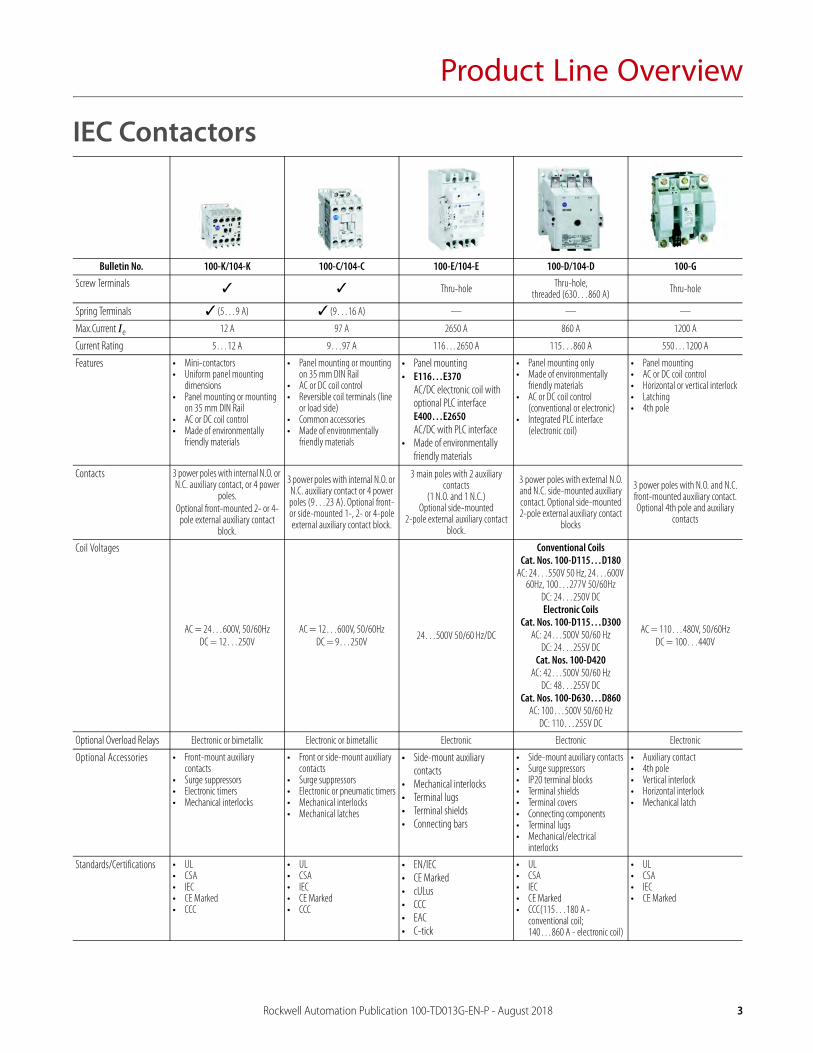
Bulletin No. 100-K/104-K 100-C/104-C 100-E/104-E 100-D/104-D 100-G
Screw Terminals ✓ ✓ Thru-hole Thru-hole, threaded (630…860 A) Thru-hole
Spring Terminals ✓ (5…9 A) ✓ (9…16 A) — — —
Max.Current Ie 12 A 97 A 2650 A 860 A 1200 A
Current Rating 5…12 A 9…97 A 116…2650 A 115…860 A 550…1200 A
Features • Mini-contactors• Uniform panel mounting
dimensions• Panel mounting or mounting
on 35 mm DIN Rail• AC or DC coil control• Made of environmentally
friendly materials
• Panel mounting or mounting on 35 mm DIN Rail
• AC or DC coil control• Reversible coil terminals (line
or load side)• Common accessories• Made of environmentally
friendly materials
• Panel mounting• E116…E370
AC/DC electronic coil with optional PLC interfaceE400…E2650AC/DC with PLC interface
• Made of environmentally friendly materials
• Panel mounting only• Made of environmentally
friendly materials• AC or DC coil control
(conventional or electronic)• Integrated PLC interface
(electronic coil)
• Panel mounting• AC or DC coil control• Horizontal or vertical interlock• Latching• 4th pole
Contacts 3 power poles with internal N.O. or N.C. auxiliary contact, or 4 power
poles.Optional front-mounted 2- or 4-
pole external auxiliary contact block.
3 power poles with internal N.O. or N.C. auxiliary contact or 4 power poles (9…23 A). Optional front- or side-mounted 1-, 2- or 4-pole external auxiliary contact block.
3 main poles with 2 auxiliary contacts
(1 N.O. and 1 N.C.)Optional side-mounted
2-pole external auxiliary contact block.
3 power poles with external N.O. and N.C. side-mounted auxiliary contact. Optional side-mounted 2-pole external auxiliary contact
blocks
3 power poles with N.O. and N.C. front-mounted auxiliary contact. Optional 4th pole and auxiliary
contacts
Coil Voltages
AC = 24…600V, 50/60HzDC = 12…250V
AC = 12…600V, 50/60HzDC = 9…250V
24…500V 50/60 Hz/DC
Conventional CoilsCat. Nos. 100-D115…D180
AC: 24…550V 50 Hz, 24…600V 60Hz, 100…277V 50/60Hz
DC: 24…250V DCElectronic Coils
Cat. Nos. 100-D115…D300AC: 24…500V 50/60 Hz
DC: 24…255V DCCat. Nos. 100-D420
AC: 42…500V 50/60 HzDC: 48…255V DC
Cat. Nos. 100-D630…D860AC: 100…500V 50/60 Hz
DC: 110…255V DC
AC = 110…480V, 50/60HzDC = 100…440V
Optional Overload Relays Electronic or bimetallic Electronic or bimetallic Electronic Electronic Electronic
Optional Accessories • Front-mount auxiliary contacts
• Surge suppressors• Electronic timers• Mechanical interlocks
• Front or side-mount auxiliary contacts
• Surge suppressors• Electronic or pneumatic timers• Mechanical interlocks• Mechanical latches
• Side-mount auxiliary contacts
• Mechanical interlocks• Terminal lugs• Terminal shields• Connecting bars
• Side-mount auxiliary contacts• Surge suppressors• IP20 terminal blocks• Terminal shields• Terminal covers• Connecting components• Terminal lugs• Mechanical/electrical
interlocks
• Auxiliary contact• 4th pole• Vertical interlock• Horizontal interlock• Mechanical latch
Standards/Certifications • UL• CSA• IEC• CE Marked• CCC
• UL• CSA• IEC• CE Marked• CCC
• EN/IEC• CE Marked• cULus• CCC• EAC• C-tick
• UL• CSA• IEC• CE Marked• CCC(115…180 A -
conventional coil; 140…860 A - electronic coil)
• UL• CSA• IEC• CE Marked
Rockwell Automation Publication 100-TD013G-EN-P - August 2018 3

Product Line Overview
Safety Contactors
Bulletin No. 100S-C/104S-C 100S-E 100S-D
Screw Terminals ✓ Thru-hole Thru-hole, threaded (630…860 A)
Max.Current Ie 97 A 750 A 860 A
Current Rating 9…97 A 116…750 A 115…860 A
Features • Positively guided/mechanically linked auxiliary contacts
• Front-mounted auxiliary contacts:– Permanently fixed– Protective cover to prevent manual operation– Red contact housing for easy identification– Incorporates IEC 947-5-1 “Mechanically Linked”
symbol– Optional gold-plated bifurcated versions
• AC and DC operating coils• SUVA third-party certification
• Mirror contact performance on auxiliary contacts• Red N.C. low-power auxiliary contact used for feedback
circuit• SUVA third-party certification• AC/ DC operating coils• "Mirror Contact" symbol on front
• Mirror contact performance on auxiliary contacts, which are required in feedback circuit for modern safety applications.
• The N.C. auxiliary contacts will not change state when a power contact welds.
• SUVA third-party certification• AC and DC operating coils• "Mirror Contact" symbol
Contacts 3 main poles with N.C. mechanically linked or mirror feedback contacts 3 main poles with N.C. mirror feedback contacts 3 main poles with N.C. mirror feedback contacts
Coil Voltages
AC = 12…600V, 50/60HzDC = 12…250V
24…500V 50/60 Hz/DC
Conventional CoilsCat. Nos. 100S-D115…D180
AC: 24…550V, 50 Hz; 24…600V, 60Hz; 100…277V, 50/60Hz
DC: 24…250V
Electronic CoilsCat. Nos. 100S-D115…D300
AC: 24…500V, 50/60 HzDC: 24…255V
Cat. Nos. 100S-D420AC: 42…500V 50/60 Hz
DC: 48…255VCat. Nos. 100S-D630…D860
AC: 100…500V, 50/60 HzDC: 110…255V
Optional Accessories • Side-mount auxiliary contacts• Surge suppressors• Electronic timers• Mechanical interlocks
• Side-mount auxiliary contacts• Terminal shields• Terminal lugs• Terminal enlargements• Terminal extensions• Connection bars for 140G molded case circuit breakers,
140MG motor protection circuit breakers, and 140MG motor circuit protectors
• Side-mount auxiliary contacts• Surge suppressors• IP20 terminal blocks• Terminal shields• Terminal covers• Connecting components• Terminal lugs• Mechanical/electrical interlocks
Standards Compliance • EN/IEC 60947-4• IEC 60947-5-1 Annex L — Mechanically Linked
Contacts• IEC 60947-4-1 Annex H — Mirror Contacts• UL 508• CSA C22.2 No. 14• EN50205
• EN/IEC 60947-4-1• IEC 60947-4-1, Annex F — Mirror Contacts• UL 60947-4-1• CSA C22.2, No. 60947-4-1
• EN/IEC 60947-4• IEC 60947-4-1• IEC 60947-4-1/A1: 2002-09, Annex F• UL 508• CSA C22.2, No. 14
Certifications • cULus Listed (File No. E3125; Guide NLDX, NLDX7)• SUVA Third-Party Certified• CE Marked
• cULus Listed (File No. E41850; Guide No. NLDX, NLDX7)• CE Marked• CCC • UL• CSA• EAC• RCM (C-tick)• SUVA Third-Party Certified
• cULus Listed (File No. E3125; Guide No. NLDX, NLDX7)• SUVA Third-Party Certified• CE Marked• CCC (115…180 A - conventional coil; 140…860 A -
electronic coil)
4 Rockwell Automation Publication 100-TD013G-EN-P - August 2018
100-K/104-K Miniature Contactors
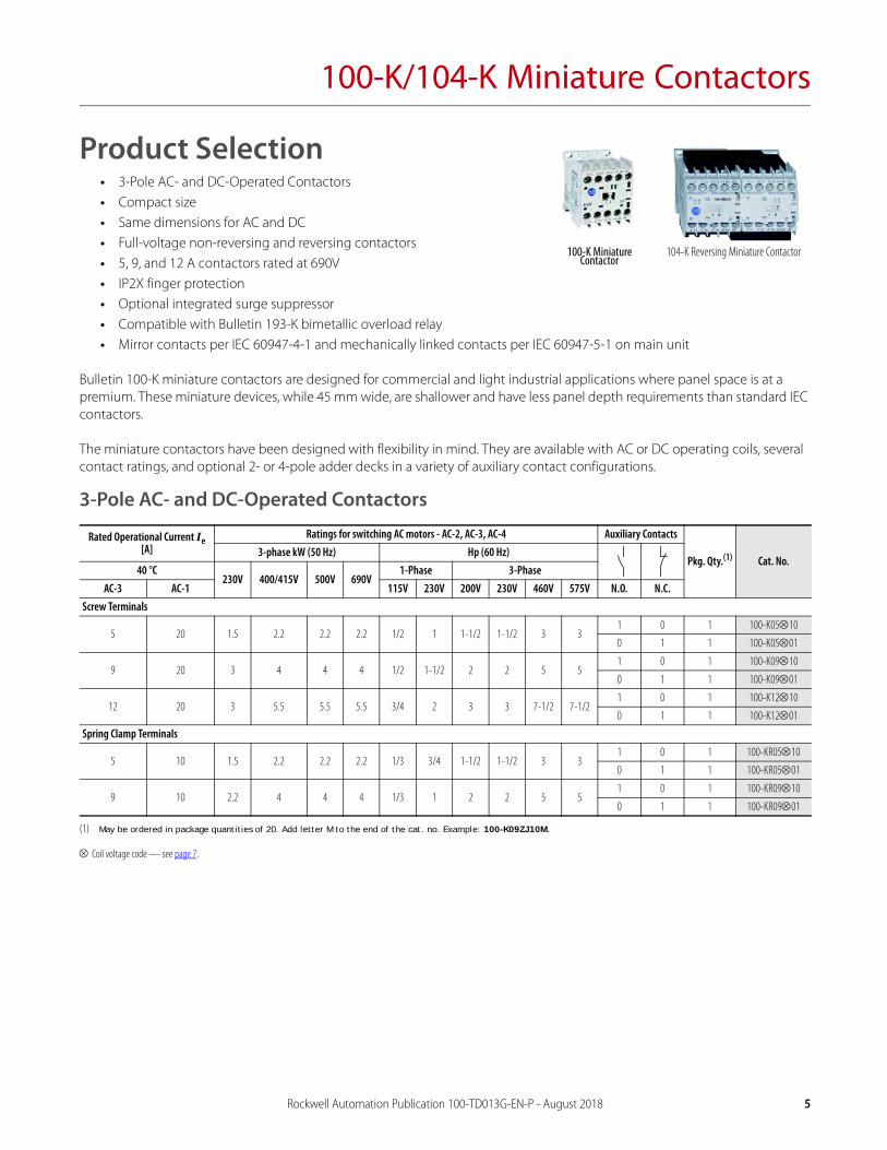
Product Selection• 3-Pole AC- and DC-Operated Contactors• Compact size• Same dimensions for AC and DC• Full-voltage non-reversing and reversing contactors• 5, 9, and 12 A contactors rated at 690V• IP2X finger protection• Optional integrated surge suppressor• Compatible with Bulletin 193-K bimetallic overload relay• Mirror contacts per IEC 60947-4-1 and mechanically linked contacts per IEC 60947-5-1 on main unit
Bulletin 100-K miniature contactors are designed for commercial and light industrial applications where panel space is at a premium. These miniature devices, while 45 mm wide, are shallower and have less panel depth requirements than standard IEC contactors.
The miniature contactors have been designed with flexibility in mind. They are available with AC or DC operating coils, several contact ratings, and optional 2- or 4-pole adder decks in a variety of auxiliary contact configurations.
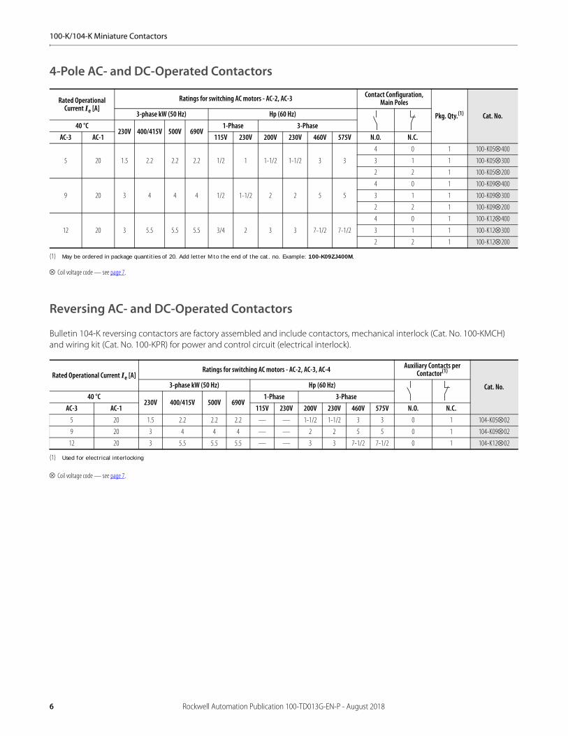
3-Pole AC- and DC-Operated Contactors
Coil voltage code — see page 7.
Rated Operational Current Ie [A]
Ratings for switching AC motors - AC-2, AC-3, AC-4 Auxiliary Contacts
Pkg. Qty.(1)
(1) May be ordered in package quantities of 20. Add letter M to the end of the cat. no. Example: 100-K09ZJ10M.
Cat. No.3-phase kW (50 Hz) Hp (60 Hz)
40 °C230V 400/415V 500V 690V
1-Phase 3-PhaseAC-3 AC-1 115V 230V 200V 230V 460V 575V N.O. N.C.
Screw Terminals
5 20 1.5 2.2 2.2 2.2 1/2 1 1-1/2 1-1/2 3 31 0 1 100-K0510
0 1 1 100-K0501
9 20 3 4 4 4 1/2 1-1/2 2 2 5 51 0 1 100-K0910
0 1 1 100-K0901
12 20 3 5.5 5.5 5.5 3/4 2 3 3 7-1/2 7-1/21 0 1 100-K1210
0 1 1 100-K1201
Spring Clamp Terminals
5 10 1.5 2.2 2.2 2.2 1/3 3/4 1-1/2 1-1/2 3 31 0 1 100-KR0510
0 1 1 100-KR0501
9 10 2.2 4 4 4 1/3 1 2 2 5 51 0 1 100-KR0910
0 1 1 100-KR0901
100-K Miniature Contactor
104-K Reversing Miniature Contactor
Rockwell Automation Publication 100-TD013G-EN-P - August 2018 5
100-K/104-K Miniature Contactors
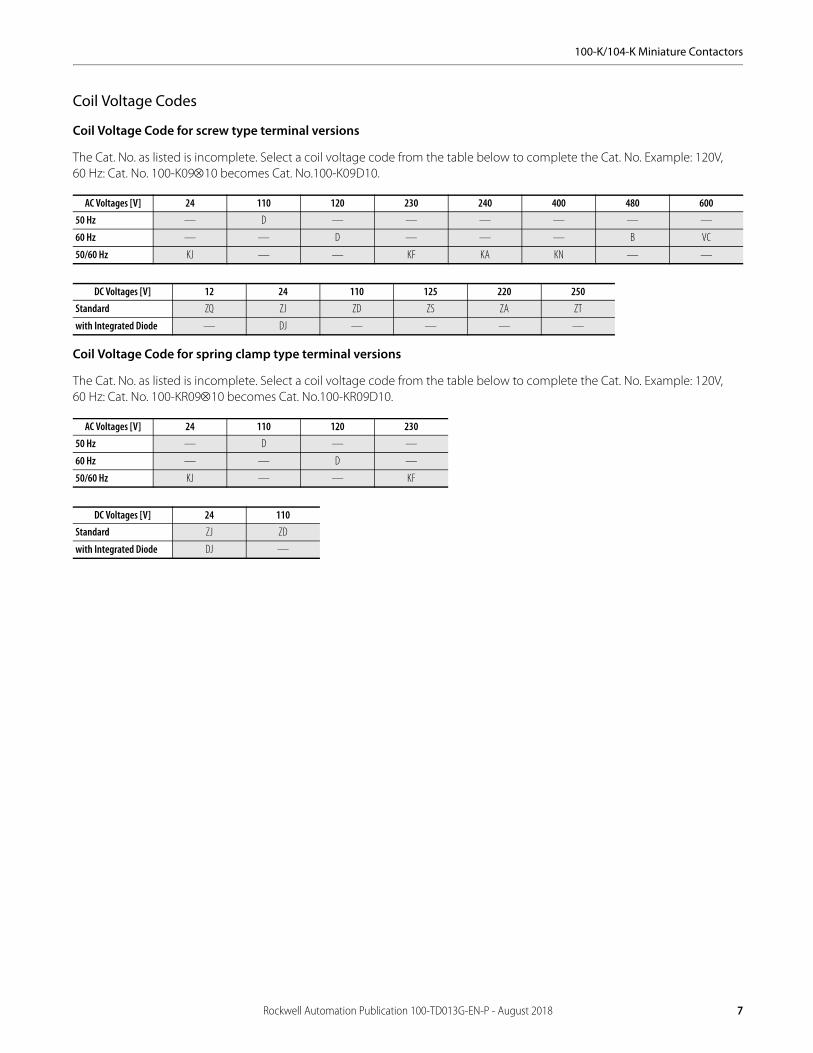
4-Pole AC- and DC-Operated Contactors
Coil voltage code — see page 7.
Reversing AC- and DC-Operated Contactors
Bulletin 104-K reversing contactors are factory assembled and include contactors, mechanical interlock (Cat. No. 100-KMCH) and wiring kit (Cat. No. 100-KPR) for power and control circuit (electrical interlock).
Coil voltage code — see page 7.
Rated Operational Current Ie [A]
Ratings for switching AC motors - AC-2, AC-3 Contact Configuration, Main Poles
Pkg. Qty.(1)
(1) May be ordered in package quantities of 20. Add letter M to the end of the cat. no. Example: 100-K09ZJ400M.
Cat. No.3-phase kW (50 Hz) Hp (60 Hz)40 °C
230V 400/415V 500V 690V1-Phase 3-Phase
AC-3 AC-1 115V 230V 200V 230V 460V 575V N.O. N.C.
5 20 1.5 2.2 2.2 2.2 1/2 1 1-1/2 1-1/2 3 3
4 0 1 100-K05400
3 1 1 100-K05300
2 2 1 100-K05200
9 20 3 4 4 4 1/2 1-1/2 2 2 5 5
4 0 1 100-K09400
3 1 1 100-K09300
2 2 1 100-K09200
12 20 3 5.5 5.5 5.5 3/4 2 3 3 7-1/2 7-1/2
4 0 1 100-K12400
3 1 1 100-K12300
2 2 1 100-K12200
Rated Operational Current Ie [A]Ratings for switching AC motors - AC-2, AC-3, AC-4 Auxiliary Contacts per
Contactor(1)
(1) Used for electrical interlocking
Cat. No.3-phase kW (50 Hz) Hp (60 Hz)40 °C
230V 400/415V 500V 690V1-Phase 3-Phase
AC-3 AC-1 115V 230V 200V 230V 460V 575V N.O. N.C.5 20 1.5 2.2 2.2 2.2 — — 1-1/2 1-1/2 3 3 0 1 104-K0502
9 20 3 4 4 4 — — 2 2 5 5 0 1 104-K0902
12 20 3 5.5 5.5 5.5 — — 3 3 7-1/2 7-1/2 0 1 104-K1202
6 Rockwell Automation Publication 100-TD013G-EN-P - August 2018
100-K/104-K Miniature Contactors
Coil Voltage Codes
Coil Voltage Code for screw type terminal versions
The Cat. No. as listed is incomplete. Select a coil voltage code from the table below to complete the Cat. No. Example: 120V, 60 Hz: Cat. No. 100-K0910 becomes Cat. No.100-K09D10.
Coil Voltage Code for spring clamp type terminal versions
The Cat. No. as listed is incomplete. Select a coil voltage code from the table below to complete the Cat. No. Example: 120V, 60 Hz: Cat. No. 100-KR0910 becomes Cat. No.100-KR09D10.
AC Voltages [V] 24 110 120 230 240 400 480 600
50 Hz — D — — — — — —
60 Hz — — D — — — B VC
50/60 Hz KJ — — KF KA KN — —
DC Voltages [V] 12 24 110 125 220 250
Standard ZQ ZJ ZD ZS ZA ZT
with Integrated Diode — DJ — — — —
AC Voltages [V] 24 110 120 230
50 Hz — D — —
60 Hz — — D —
50/60 Hz KJ — — KF
DC Voltages [V] 24 110
Standard ZJ ZD
with Integrated Diode DJ —
Rockwell Automation Publication 100-TD013G-EN-P - August 2018 7

100-K/104-K Miniature Contactors
Assignment of Contacts
Table valid for: AC / DC = 0.85…1.1 x Us, Tamb. = -25 °C…+60 °C, normal position (horizontal rail mounting)
Device Combinations in Accordance with IEC 60947-1 / -4-1
Auxiliary Contact Blocks(1) 100-K Miniature Contactors (AC and DC Control)
Circuit Diagram Control
100-K0510100-K0910100-K1210
100-K0501100-K0901100-K1201
100-K05400100-K09400100-K12400
100-K05300100-K09300100-K12300
100-K05200100-K09200100-K12200
Front Mounting
100-KFA02E AC/DC (2) 01 + 02 = 03 (3) (2) (2)(3) —
100-KFC02 AC/DC 10 + 02 = 12 — 00 + 02 = 02 00 + 02 = 02 (3) —
100-KFA11E AC/DC (2) 01 + 11 = 12 (2) (2) (2)
100-KFB11 AC/DC 10 + 11 = 21 — 00 + 11 = 11 00 + 11 = 11 00 + 11 = 11
100-KFC11 AC/DC 10 + 11 = 21 (2) 00 + 11 = 11 00 + 11 = 11 00 + 11 = 11
100-KFA20E AC/DC (2) 01 + 20 = 21 (2) (2) (2)
100-KFC20 AC/DC 10 + 20 = 30 (2) 00 + 20 = 20 00 + 20 = 20 00 + 20 = 20
100-KFA04E AC/DC (2)(3) — (2)(3) — —
100-KFC04 AC/DC 10 + 04 = 14 (3) — 00 + 04 = 04 (3) — —
100-KFA13E AC/DC (2) 01 + 13 = 14 (3) (2) (2)(3) —
100-KFC13 AC/DC 10 + 13 = 23 (2)(3) 00 + 13 = 13 00 + 13 = 13 (3) —
100-KFA22Z AC/DC (2) 01 + 22 = 23 (3) (2) (2)(3) —
100-KFB22 AC/DC 10 + 22 = 32 — 00 + 22 = 22 00 + 22 = 22 (3) —
100-KFC22 AC/DC 10 + 22 = 32 (2)(3) 00 + 22 = 22 00 + 22 = 22 (3) —
100-KFA31Z AC/DC (2) — (2)(4) — —
14
13
2
1
4
3
6
5A1
A2
K1
22
21
2
1
4
3
6
5A1
A2
K1
8
7
2
1
4
3
6
5A1
A2
K1
2
1
4
3
R8
R7A1
A2
K1
6
5
2
1
4
3
R8
R7A1
A2
K1
R6
R5
51 61
6252
21 31
3222
53 61
54 62
21
22
33
34
23 31
24 32
53 63
54 64
23 33
24 34
71 81
8272
51 61
6252
41 51
5242
21 31
3222
53 61 71
7254 62
81
82
23 31 41
4224 32
51
52
53 83 61 71
7254 84 62
43 53 21 31
3244 54 22
23 53 31 41
4224 54 32
73 83 61
74 84 62
53
54
8 Rockwell Automation Publication 100-TD013G-EN-P - August 2018

100-K/104-K Miniature Contactors
100-KFC31 AC/DC 10 + 31 = 41 (4) — 00 + 31 = 31 (4) — —
100-KFA40E AC/DC (2) (2) (2) (2)
100-KFC40 AC/DC 10 + 40 = 50 (2) 00 + 40 = 40 00 + 40 = 40 00 + 40 = 40
(1) For other operating limits, please contact your local Rockwell Automation sales office or Allen-Bradley distributor(2) Combination possible but not recommended, due to repeating or not consecutive sequence numbering(3) Tamb max. +40 °C
(4) Tamb max. +40 °C and only allowed for coil voltage 24V DC or 230V AC
Auxiliary Contact Blocks(1) 100-K Miniature Contactors (AC and DC Control)
Circuit Diagram Control
100-K0510100-K0910100-K1210
100-K0501100-K0901100-K1201
100-K05400100-K09400100-K12400
100-K05300100-K09300100-K12300
100-K05200100-K09200100-K12200
14
13
2
1
4
3
6
5A1
A2
K1
22
21
2
1
4
3
6
5A1
A2
K1
8
7
2
1
4
3
6
5A1
A2
K1
2
1
4
3
R8
R7A1
A2
K1
6
5
2
1
4
3
R8
R7A1
A2
K1
R6
R5
43 53 31
44 54 32
23
24
53 63 73 83
8454 64 74
23 33 43 53
5424 34 44
Rockwell Automation Publication 100-TD013G-EN-P - August 2018 9
100-K/104-K Miniature Contactors
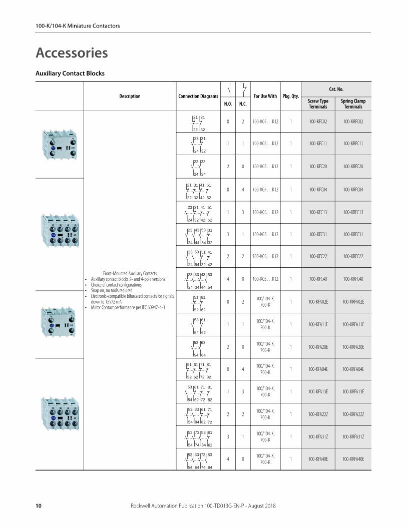
AccessoriesAuxiliary Contact Blocks
Description Connection Diagrams For Use With Pkg. Qty.Cat. No.
N.O. N.C. Screw Type Terminals
Spring Clamp Terminals
Front-Mounted Auxiliary Contacts• Auxiliary contact blocks 2- and 4-pole versions• Choice of contact configurations• Snap on, no tools required• Electronic-compatible bifurcated contacts for signals
down to 15V/2 mA• Mirror Contact performance per IEC 60947-4-1
0 2 100-K05…K12 1 100-KFC02 100-KRFC02
1 1 100-K05…K12 1 100-KFC11 100-KRFC11
2 0 100-K05…K12 1 100-KFC20 100-KRFC20
0 4 100-K05…K12 1 100-KFC04 100-KRFC04
1 3 100-K05…K12 1 100-KFC13 100-KRFC13
3 1 100-K05…K12 1 100-KFC31 100-KRFC31
2 2 100-K05…K12 1 100-KFC22 100-KRFC22
4 0 100-K05…K12 1 100-KFC40 100-KRFC40
0 2100/104-K,
700-K1 100-KFA02E 100-KRFA02E
1 1100/104-K,
700-K1 100-KFA11E 100-KRFA11E
2 0100/104-K,
700-K1 100-KFA20E 100-KRFA20E
0 4100/104-K,
700-K1 100-KFA04E 100-KRFA04E
1 3100/104-K,
700-K1 100-KFA13E 100-KRFA13E
2 2100/104-K,
700-K1 100-KFA22Z 100-KRFA22Z
3 1100/104-K,
700-K1 100-KFA31Z 100-KRFA31Z
4 0100/104-K,
700-K1 100-KFA40E 100-KRFA40E
21 31
3222
23 31
24 32
23 33
24 34
41 51
5242
21 31
3222
23 31 41
4224 32
51
52
43 53 31
44 54 32
23
24
23 53 31 41
4224 54 32
23 33 43 53
5424 34 44
51 61
6252
53 61
54 62
53 63
54 64
71 81
8272
51 61
6252
53 61 71
7254 62
81
82
53 83 61 71
7254 84 62
73 83 61
74 84 62
53
54
53 63 73 83
8454 64 74
10 Rockwell Automation Publication 100-TD013G-EN-P - August 2018

100-K/104-K Miniature Contactors
Control Modules
Timers
Connecting Components
Description Connection Diagrams For Use With Pkg. Qty. Cat. No.
Mechanical Interlock• For interlocking of two adjacent contactors No added width to contactor assembly• Front mount plug-in type• Optional auxiliary contact blocks and suppressor modules mount onto the interlock
100/104-K/-KR, 700-K/-KR 1 100-KMCH
Surge Suppressor• Plug-in type• Limits surge voltage on coil drop-off
RC Suppressor
24…48V AC100/104-K/-KR,
700-K/-KR
1(1)
(1) May be ordered in package quantities of 10. Add letter M to the end of the cat. no. Example: 100-KFSC50M.
100-KFSC50
110…280V AC 1(1) 100-KFSC280
380…480V AC 1(1) 100-KFSC480
MOV Suppressor
12…55V AC, 12…77V DC100/104-K/-KR,
700-K/-KR
1(1) 100-KFSV55
56…136V AC, 78…180V DC 1(1) 100-KFSV136
137…277V AC, 181…250V DC 1(1) 100-KFSV277
Diode Suppressor 12…250V DC 100/104-K/-KR, 700-K/-KR 1(1) 100-KFSD250
Description Connection Diagrams For Use With Pkg. Qty. Cat. No.
Solid-State Timing Element• 110…250V AC or DC• Includes 35 mm Hat Rail adapter
On-Delay,0.1…3 s
100/104-K, 700-K 10
100-KT3S
On-Delay,1…30 s
100-KT30S
Description For Use With Pkg. Qty. Cat. No.
ECO Connecting Module — 12 A• For DOL and reversing starters• Eco-starters mount on single DIN Rail (140M on DIN Rail)• Electrical and mechanical interconnection of 140M and 100-K
contactors
Connects:140M-C circuit breakers with 100-K contactors
140M-C to 100- K 1(1)
(1) May be ordered in package quantities of 10. Add letter M to the end of the cat. no. Example: 140M-C-PEK12M.
140M-C-PEK12
Power Wiring Kit• For Reversing and Star/Delta combinations. Star-point bridge
not included.• Min. interruption time 50 ms
100-K 1 100-KPR
Feeder Terminal for Compact Bus Bars• Max. current 34 A Supply of compact bus bars 100-K 1 100-KWT
Three-Phase Compact Bus Bars• Max. current 34 A
For 1005K, 5…12 A contactors 45 mm spacing (3 connections)(2)
(2) Combinations possible. Example: For 6 contactor connections use one cat. no. 100-KW453 and one cat. no. 100-KW454.
100-K 1 100-KW453
For 100-K, 5…12 A contactors 45 mm spacing (4 connections)(2) 100-K 1 100-KW454
S1
NK1
1
2
O / I
~
2 4 6
1 3 5
K1M2 4 6
1 3 5
K2M21
22
21
22
- (L2)
Rockwell Automation Publication 100-TD013G-EN-P - August 2018 11
100-K/104-K Miniature Contactors
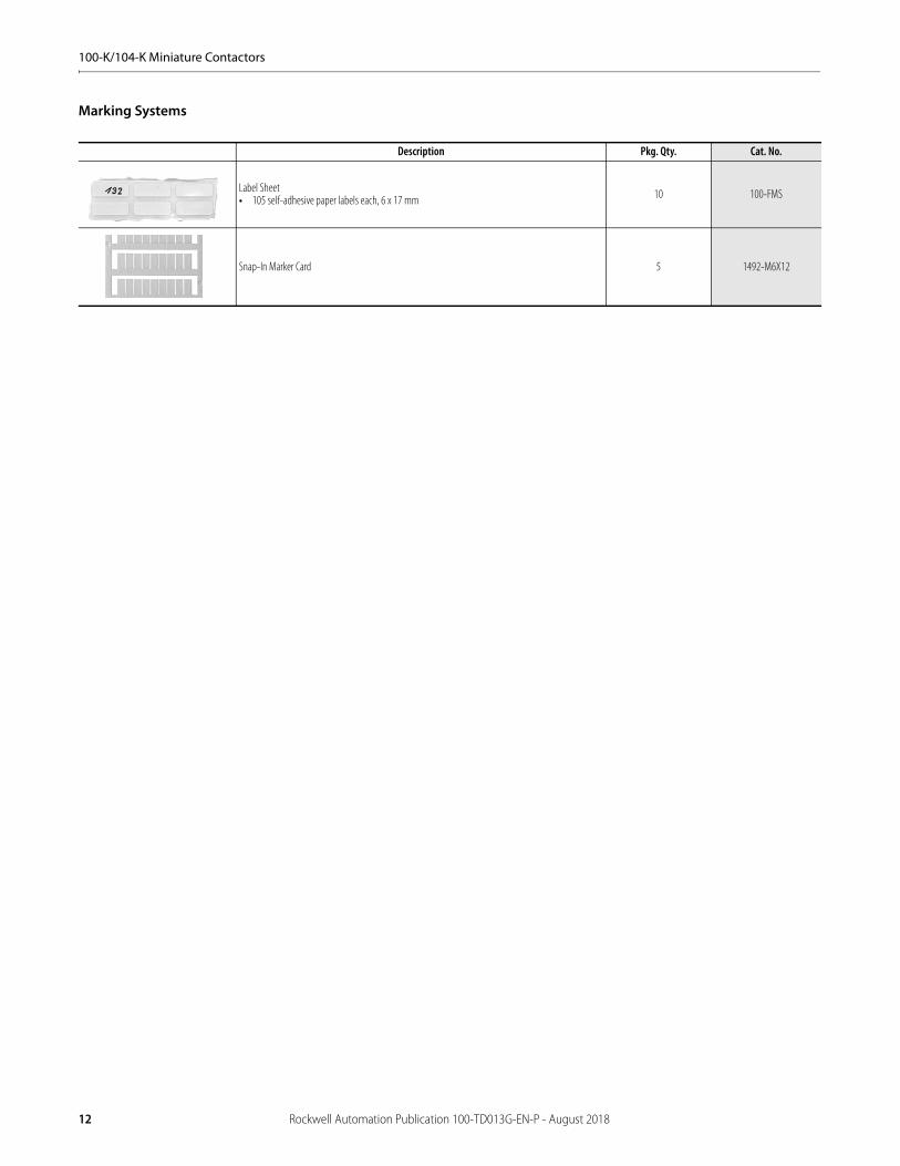
Marking Systems
Description Pkg. Qty. Cat. No.
Label Sheet• 105 self-adhesive paper labels each, 6 x 17 mm 10 100-FMS
Snap-In Marker Card 5 1492-M6X12
12 Rockwell Automation Publication 100-TD013G-EN-P - August 2018

100-K/104-K Miniature Contactors
Specifications100-KR 100/104-K
05 09 05 09 12AC-1 Active Power Load (50 Hz); Ambient temperature 40 °C
Rated Operational Current, Ie
≤500V [A] 10 10 20 20 20
690V [A] 10 10 20 20 20
230V [kW] 4 4 8 8 8
240V [kW] 4 4 8.3 8.3 8.3
400V [kW] 6.9 6.9 14 14 14
415V [kW] 7 7 14 14 14
500V [kW] 8.7 8.7 17 17 17
690V [kW] 12 12 24 24 24
AC-1 Active Power Load (50 Hz); Ambient temperature 60 °C
Rated Operational Current, Ie
≤500V [A] 10 10 16 16 16
690V [A] 10 10 16 16 16
230V [kW] 4 4 6.4 6.4 6.4
240V [kW] 4 4 6.7 6.7 6.7
400V [kW] 6.9 6.9 11 11 11
415V [kW] 7 7 12 12 12
500V [kW] 8.7 8.7 14 14 14
690V [kW] 12 12 19 19 19
Switching of 3-phase Motors; (50 Hz) Ambient temperature 60 °C, AC-2, AC-3
Rated Operational Current, Ie
230V [A] 6.3 8.5 6.3 11.3 11.3
240V [A] 6.3 8.5 6.3 11.3 11.3
400V [A] 4.9 8.5 4.9 8.5 11.5
415V [A] 4.9 8.5 4.9 8.5 11.5
500V [A] 3.9 6.8 3.9 6.8 9.2
690V [A] 2.8 4.9 2.8 4.9 6.7
230V [kW] 1.5 2.2 1.5 3 3
240V [kW] 1.5 2.2 1.5 3 3
400V [kW] 2.2 4 2.2 4 5.5
415V [kW] 2.2 4 2.2 4 5.5
500V [kW] 2.2 4 2.2 4 5.5
690V [kW] 2.2 4 2.2 4 5.5
Load Carrying Capacity per UL/CSAGeneral Purpose Current (enclosed) [A] 9 9 12 15 18
Rated power (enclosed)1-phase
115V [A] 7.2 7.2 9.8 9.8 13.8
230V [A] 6.9 8 8 10 12
115V [Hp] 1/3 1/3 0.5 0.5 0.75
230V [Hp] 3/4 1 1 1.5 2
Rated power (enclosed)3-phase
200V [A] 6.9 7.8 6.9 7.8 11
230V [A] 6 6.8 6 6.8 9.6
460V [A] 4.8 7.6 4.8 7.6 11
575V [A] 3.9 6.1 3.9 6.1 9
200V [Hp] 1.5 2 1.5 2 3
230V [Hp] 1.5 2 1.5 2 3
460V [Hp] 3 5 3 5 7.5
575V [Hp] 3 5 3 5 7.5
100/104-K 05 09 12Switching of 3-phase Motors, (50 Hz); Ambient temperature 60 °C, AC-4
230V [A] 6.3 11.3 11.3
240V [A] 6.3 11.3 11.3
400V [A] 4.9 8.5 11.5
415V [A] 4.9 8.5 11.5
500V [A] 3.9 6.8 9.2
690V [A] 2.8 4.9 6.7
230V [Hp] 1.5 3 3
240V [Hp] 1.5 3 3
400V [Hp] 2.2 4 5.5
415V [Hp] 2.2 4 5.5
500V [Hp] 2.2 4 5.5
690V [Hp] 2.2 4 5.5
AC-4 at approximately 200,000 operations230V [A] 2.3 3.9 3.9
240V [A] 2.3 3.9 3.9
400/415V [A] 2 3.6 3.6
500V [A] 1.9 3.2 3.2
230V (1)
(1) Power ratings at 50 Hz: Preferred values according to IEC 60072-1
[Hp] 0.37 0.75 0.75
240V (1) [Hp] 0.37 0.75 0.75
400V (1) [Hp] 0.75 1.5 1.5
415V (1) [Hp] 0.75 1.5 1.5
500V (1) [Hp] 0.75 1.5 1.5
Max. switching frequency Ops/hour 250 250 250
Wye-Delta (60 Hz)200V [Hp] 2.2 3 5
230V [Hp] 2.2 3 5
460V [Hp] 5 7.5 10
575V [Hp] 5 7.5 10
Star-Delta Starting (50 Hz)≤ 230V [A] 11.3 20 20
≤ 240V [A] 11.3 20 20
400V [A] 8.5 15.5 15.5
415V [A] 8.5 15.5 15.5
500V [A] 6.8 12.4 12.4
690V [A] 4.9 8.9 8.9
230V (1) [kW] 3 5.5 5.5
240V (1) [kW] 3 5.5 5.5
400V (1) [kW] 4 7.5 7.5
415V (1) [kW] 4 7.5 7.5
500V (1) [kW] 4 7.5 7.5
690V (1) [kW] 4 7.5 7.5
Rockwell Automation Publication 100-TD013G-EN-P - August 2018 13

100-K/104-K Miniature Contactors
100/104-K 05 09 12Switching of Power Transformers, AC-6a (50 Hz)Inrush Current
=nRated transformer current
n= 30
≤ 230V [A] 2.9 5.4 5.4
≤ 240V [A] 2.9 5.4 5.4
≤ 400V [A] 2.4 4.1 5.4
≤ 415V [A] 2.4 4.1 5.4
≤ 500V [A] 1.8 3.2 3.2
230V [kVA] 1.2 2 2
240V [kVA] 1.2 2 2
400V [kVA] 1.7 2.8 3.4
415V [kVA] 1.7 2.8 3.4
500V [kVA] 1.7 2.8 3.4
690V [kVA] 2 4 5
Switching of LampsGas discharge lamps AC-5a, 40 °C
open [A] 18 18 18
enclosed [A] 14.5 14.5 14.5
Individually compensated:
Max. capacitance at expected
Short-circuit current of10 kA [F] 750 750 750
20 kA [F] 400 400 400
Filament AC-5b 230/240V [A] 5 9 9
Switching of Low Inductive Loads in Home Appliances and Similar Applications per IEC 61095 (50 Hz)
AC-7a230V [A] 20 20 20
400V [A] 20 20 20
Switching of Motor Load for Home Appliances (50 Hz)
AC-7b230V [A] 6 11 11
400V [A] 6 11 11
Switching of Hermetically Sealed Cooling Compressor Motors - manual reset of overload release (50 Hz)
AC-8a400V [A] 11 18 18
500V [A] 10 15 15
Switching of DC LoadsNon-inductive or slightly inductive loads or resistance furnaces DC-1, 60 °C
1 pole
24V [A] 6 9 9
48/60V [A] 4/1 6/1.5 6/1.5
110V [A] 0.6 1 1
220V [A] 0.2 0.3 0.3
440V [A] 0.08 0.1 0.1
2 poles in series
24V [A] 6 9 9
48/60V [A] 6 8 8
110V [A] 4 6 6
220V [A] 0.8 1.2 1.2
440V [A] 0.2 0.3 0.3
3 poles in series
24V [A] 6 9 9
48/60V [A] 6 9 9
110V [A] 6 9 9
220V [A] 3 4 4
440V [A] 0.4 0.6 0.6
Shunt-wound MotorsStarting, reverse current braking, reversing, stepping DC-3, 60 °C
3 poles in series
24V [A] 5 9 9
48/60V [A] 4 6 6
110V [A] 2 3 3
220V [A] 0.8 1.2 1.2
440V [A] 0.15 0.2 0.2
Series-wound MotorsStarting, reverse current braking, reversing, stepping DC-5, 60 °C
3 poles in series
24V [A] 5 9 9
48/60V [A] 2 3 3
110V [A] 0.6 1 1
220V [A] 0.1 0.1 0.1
Short Time Withstand ICW, 60 °C 10 s [A] 60 96 96
Resistance and Power DissipationMain current circuit resistance [m] 2.2 2.2 2.2
Power dissipation by all circuits at Ie AC-3/400V [W] 0.3 0.9 0.9
Total power dissipation
At Ie AC-3/400VAC control [W] 2.1 2.7 2.7
DC control(electronic)
[W] 2.9 3.5 3.5
LifespanMechanical AC control [Mil. operations] 15 15 15
Mechanical DC control [Mil. operations] 15 15 15
Electrical AC-3 (400 V) [Mil. operations] 0.7 0.7 0.7
Weight
ACNon-Rev. kg (lbs.) 0.16 (0.35)
Rev. kg (lbs.) 0.4 (0.88)
DCNon-Rev. kg (lbs.) 0.2 (0.44)
Rev. kg (lbs.) 0.48 (1.06)
100-KR 100/104-K05 09 05 09 12
Conductor Cross Sections - Main Contacts Terminal type(1)
(1) Pozidriv No. 2 / Blade No. 3 screw
1 conductor [mm2] 0.50…2.5 0.75…2.5
2 conductors [mm2] 0.50…2.5 0.75…2.5
1 conductor [mm2] 0.75…2.5 (2)
(2) Fine- or coarse-stranded only
1…4
2 conductors [mm2] 0.75…2.5 (2) 1…2.5+ 1…4
Recommended torque [N•m] — 1.2
Cros s s ection per UL/CSA [AWG] 18…14(2) 18…12
Recommended torque [lb-in] — 10.6
100/104-K 05 09 12
14 Rockwell Automation Publication 100-TD013G-EN-P - August 2018
100-K/104-K Miniature Contactors
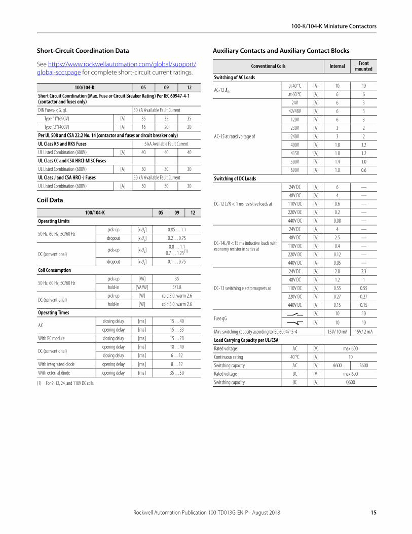
Short-Circuit Coordination Data
See https://www.rockwellautomation.com/global/support/global-sccr.page for complete short-circuit current ratings.
Coil Data
Auxiliary Contacts and Auxiliary Contact Blocks
100/104-K 05 09 12Short Circuit Coordination (Max. Fuse or Circuit Breaker Rating) Per IEC 60947-4-1 (contactor and fuses only)DIN Fuses- gG, gL 50 kA Available Fault Current
Type "1"(690V) [A] 35 35 35
Type "2"(400V) [A] 16 20 20
Per UL 508 and CSA 22.2 No. 14 (contactor and fuses or circuit breaker only)UL Class K5 and RK5 Fuses 5 kA Available Fault Current
UL Listed Combination (600V) [A] 40 40 40
UL Class CC and CSA HRCI-MISC FusesUL Listed Combination (600V) [A] 30 30 30
UL Class J and CSA HRCI-J Fuses 50 kA Available Fault Current
UL Listed Combination (600V) [A] 30 30 30
100/104-K 05 09 12Operating Limits
50 Hz, 60 Hz, 50/60 Hzpick-up [x Us] 0.85…1.1
dropout [x Us] 0.2…0.75
DC (conventional)pick-up [x Us]
0.8…1.10.7…1.25(1)
(1) For 9, 12, 24, and 110V DC coils
dropout [x Us] 0.1…0.75
Coil Consumption
50 Hz, 60 Hz, 50/60 Hzpick-up [VA] 35
hold-in [VA/W] 5/1.8
DC (conventional)pick-up [W] cold 3.0, warm 2.6
hold-in [W] cold 3.0, warm 2.6
Operating Times
ACclosing delay [ms] 15…40
opening delay [ms] 15…33
With RC module closing delay [ms] 15…28
DC (conventional)opening delay [ms] 18…40
closing delay [ms] 6…12
With integrated diode opening delay [ms] 8…12
With external diode opening delay [ms] 35…50
Conventional Coils Internal Front mounted
Switching of AC Loads
AC-12 Ithat 40 °C [A] 10 10
at 60 °C [A] 6 6
AC-15 at rated voltage of
24V [A] 6 3
42/48V [A] 6 3
120V [A] 6 3
230V [A] 3 2
240V [A] 3 2
400V [A] 1.8 1.2
415V [A] 1.8 1.2
500V [A] 1.4 1.0
690V [A] 1.0 0.6
Switching of DC Loads
DC-12 L/R < 1 ms res is tive loads at
24V DC [A] 6 —
48V DC [A] 4 —
110V DC [A] 0.6 —
220V DC [A] 0.2 —
440V DC [A] 0.08 —
DC-14L/R <15 ms inductive loads with economy resistor in series at
24V DC [A] 4 —
48V DC [A] 2.5 —
110V DC [A] 0.4 —
220V DC [A] 0.12 —
440V DC [A] 0.05 —
DC-13 switching electromagnets at
24V DC [A] 2.8 2.3
48V DC [A] 1.2 1
110V DC [A] 0.55 0.55
220V DC [A] 0.27 0.27
440V DC [A] 0.15 0.15
Fuse gG[A] 10 10
[A] 10 10
Min. switching capacity according to IEC 60947-5-4 15V/ 10 mA 15V/ 2 mA
Load Carrying Capacity per UL/CSARated voltage AC [V] max.600
Continuous rating 40 °C [A] 10
Switching capacity AC [A] A600 B600
Rated voltage DC [V] max.600
Switching capacity DC [A] Q600
Rockwell Automation Publication 100-TD013G-EN-P - August 2018 15

100-K/104-K Miniature Contactors
General
Standards Compliance and Certifications
Attribute ValueRated Isolation Voltage Ui
IEC [V] 690
UL,CSA [V] 600
Rated Impulse Voltage Withstand Uimp [kV] 6
Rated Voltage Ue
AC 50/60 Hz [V] 230, 240, 400, 415, 460, 500, 575, 690
DC [V] 24, 48, 110, 220, 440
Insulation Class of the CoilClass F per IEC 60085
Class 105 insulation system per UL 508
Rated coil frequency AC 50/60 Hz, DC
Ambient Temperature
Storage [°C] -55…+80
Operation at rated voltage [°C] -25…+60
at 70 °C 15% current reduction against 60 °C values
Climatic Withstand IEC60068-2-30
Max. Altitude of Installation Site [m] 2000 NN, per IEC60947-4
Protection Class IP2X
Single contactor cover —
Contactor with frame terminal block —
Auxiliary contact IP2X
Protection against Accidental Contact —
Resistance to Shock IEC60068-2
Resistance to Vibration IEC60068-2
Mechanically Linked Contacts IEC60947-5-1,AnnexL 100-K…(on main device)
Mirror Contacts IEC60947-4 Annex F 100-K…+100-KF…
Standards Compliance Certifications
IEC/EN 60947-1,-4-1,-5-1,-5-4 CE Marked
UL 508 CCC
CSA 22.2. No. 14 cULus Listed (File No. E41850, Guide NLDX, NLDX7)
NF F 62-000
Meets the material restrictions for European Directive 2002/95/IEC-EU-RoHS
16 Rockwell Automation Publication 100-TD013G-EN-P - August 2018
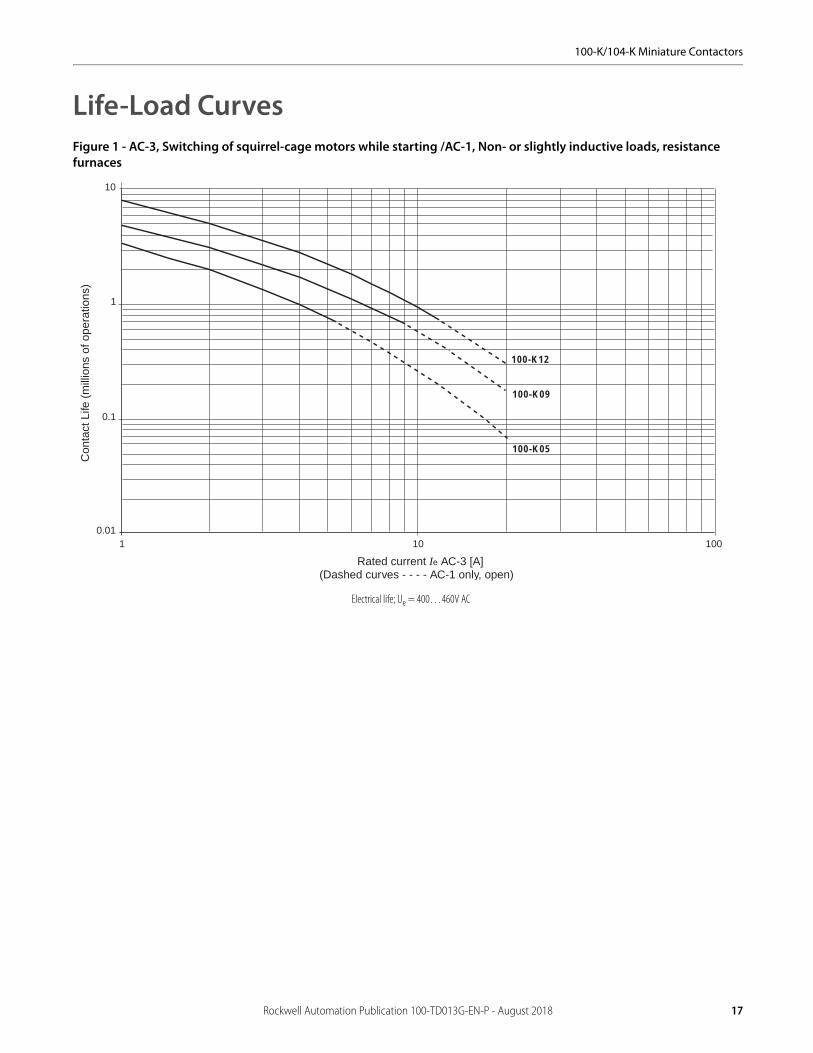
100-K/104-K Miniature Contactors
Life-Load CurvesFigure 1 - AC-3, Switching of squirrel-cage motors while starting /AC-1, Non- or slightly inductive loads, resistance furnaces
100-K05
100-K09
100-K12
0.011 10 100
1
0.1
10
Rated current Ie AC-3 [A](Dashed curves - - - - AC-1 only, open)
Con
tact
Life
(m
illio
ns o
f ope
ratio
ns)
Electrical life; Ue = 400…460V AC
Rockwell Automation Publication 100-TD013G-EN-P - August 2018 17

100-K/104-K Miniature Contactors
Figure 2 - AC-4, Stepping of squirrel-cage motors
0.010.1 1 10
1
0.1
10
100-K05
100-K09; 100-K12
Rated current Ie AC-4 [A]
Con
tact
Life
(m
illio
ns o
f ope
ratio
ns)
Electrical life; Ue = 400…460V AC
18 Rockwell Automation Publication 100-TD013G-EN-P - August 2018

100-K/104-K Miniature Contactors
Approximate DimensionsDimensions are shown in millimeters (inches). Dimensions are not intended for manufacturing purposes.
Figure 3 - 100-K Miniature Contactor with 193-K Overload Relay
Figure 4 - Mounting Position
49 (1-15/16)
4 (5/32)
108.
2 (4
-1/4
) 56 (
2-13
/64)
54 (
2-1/
8)
35 (1-25/64)
44.9 (1-25/32)
50 (
1-31
/32)
63.5 (2-1/2)
78.7 (3-7/64)
35.2 (1-25/64)
49.2
(1-
15/1
6)
36.9 (1-29/64)
25° 25°
12
-Minimum distance to grounded parts or walls
*)
*)
180°
Rockwell Automation Publication 100-TD013G-EN-P - August 2018 19

100-K/104-K Miniature Contactors
Notes:
20 Rockwell Automation Publication 100-TD013G-EN-P - August 2018

100-C/104-C, 100S-C/104S-C, 100Q-C Contactors
Product Selection—100-C/104-C Contactors• Compact sizes from 4…55 kW/5…75 Hp (9…97 A)• Common ac5cessories for all contactor sizes• Front and side mounting of auxiliary contacts• Electronic and pneumatic timing modules• Space-saving coil-mounted control modules• Reversible coil terminations (line or load side)• All devices can be attached to 35 mm DIN mounting Rail• Environmentally friendly materials
The Bulletin 100-C/104-C IEC contactor family, along with a wide range of common accessories and Bulletin 193 solid-state overload relays, provides the most compact and flexible starter component system available.
3-Pole AC- and DC-operated Contactors
Coil voltage code and terminal position—see page 24
Rated Operational Current Ie [A]Ratings for switching AC motors - AC-2, AC-3, AC-4 Auxiliary Contacts
Cat. No.(1)
(1) For screwlesss terminals on 100-C09…C16, add an “R” after the letter “C” in the catalog number. Example: Cat. No. 100-C0910 becomes 100-CR0910. The AC-1 rating for the 100-CR is limited to 25 A.
3-phase kW (50 Hz) Hp (60 Hz)40 °C
230V 400/415V 500V 690V1-Phase 3-Phase
AC-3 AC-1 115V 230V 200V 230V 460V 575V N.O. N.C.
9 32 3 4 4 4 1/2 1-1/12 2 2 5 7-1/121 0 100-C0910
0 1 100-C0901
12 32 4 5.5 5.5 5.5 1/2 2 3 3 7-1/2 101 0 100-C1210
0 1 100-C1201
16 32 5.5 7.5 7.5 7.5 1 3 5 5 10 151 0 100-C1610
0 1 100-C1601
23 32 7.5 11 13 10 2 3 5 7-1/2 15 151 0 100-C2310
0 1 100-C2301
30 65 10 15 15 15 2 5 7-1/2 10 20 25
0 0 100-C3000
1 0 100-C3010
0 1 100-C3001
37 65 11 18.5/20 20 18.5 3 5 10 10 25 30
0 0 100-C3700
1 0 100-C3710
0 1 100-C3701
43 85 13 22 25 22 3 7-1/2 10 15 30 30
0 0 100-C4300
1 0 100-C4310
0 1 100-C4301
55 85 15 30 30 30 5 10 15 20 40 40
0 0 100-C5500
1 0 100-C5510
0 1 100-C5501
60 100 18.5 32 37 32 5 10 15 20 40 50
0 0 100-C6000
1 0 100-C6010
0 1 100-C6001
72 100 22 40 45 40 5 15 20 25 50 60
0 0 100-C7200
1 0 100-C7210
0 1 100-C7201
85 100 25 45 55 45 7-1/2 15 25 30 60 60
0 0 100-C8500
1 0 100-C8510
0 1 100-C8501
97 130 30 55 55 55 10 20 30 30 75 75
0 0 100-C9700
1 0 100-C9710
0 1 100-C9701
100-C Contactor 104-C Reversing Contactor
Rockwell Automation Publication 100-TD013G-EN-P - August 2018 21
100-C/104-C, 100S-C/104S-C, 100Q-C Contactors
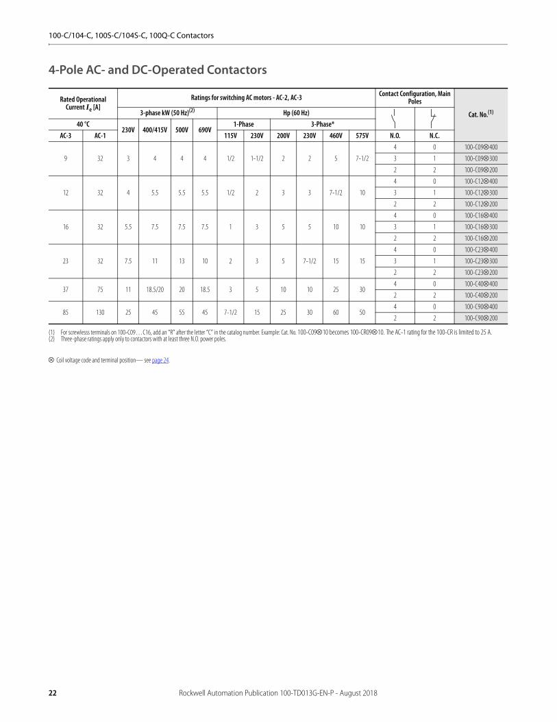
4-Pole AC- and DC-Operated Contactors
Coil voltage code and terminal position— see page 24.
Rated Operational Current Ie [A]
Ratings for switching AC motors - AC-2, AC-3 Contact Configuration, Main Poles
Cat. No.(1)
(1) For screwlesss terminals on 100-C09…C16, add an “R” after the letter “C” in the catalog number. Example: Cat. No. 100-C0910 becomes 100-CR0910. The AC-1 rating for the 100-CR is limited to 25 A.
3-phase kW (50 Hz)(2)
(2) Three-phase ratings apply only to contactors with at least three N.O. power poles.
Hp (60 Hz)40 °C
230V 400/415V 500V 690V1-Phase 3-Phase*
AC-3 AC-1 115V 230V 200V 230V 460V 575V N.O. N.C.
9 32 3 4 4 4 1/2 1-1/2 2 2 5 7-1/2
4 0 100-C09400
3 1 100-C09300
2 2 100-C09200
12 32 4 5.5 5.5 5.5 1/2 2 3 3 7-1/2 10
4 0 100-C12400
3 1 100-C12300
2 2 100-C12200
16 32 5.5 7.5 7.5 7.5 1 3 5 5 10 10
4 0 100-C16400
3 1 100-C16300
2 2 100-C16200
23 32 7.5 11 13 10 2 3 5 7-1/2 15 15
4 0 100-C23400
3 1 100-C23300
2 2 100-C23200
37 75 11 18.5/20 20 18.5 3 5 10 10 25 304 0 100-C40400
2 2 100-C40200
85 130 25 45 55 45 7-1/2 15 25 30 60 504 0 100-C90400
2 2 100-C90200
22 Rockwell Automation Publication 100-TD013G-EN-P - August 2018
100-C/104-C, 100S-C/104S-C, 100Q-C Contactors
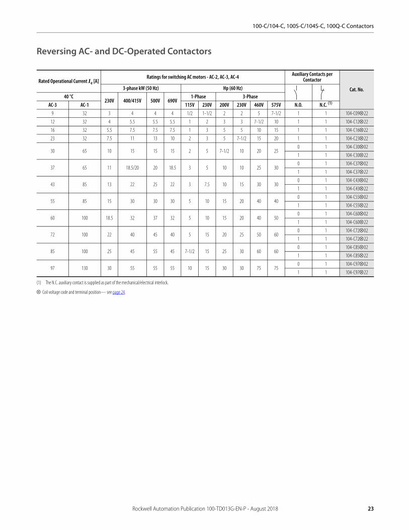
Reversing AC- and DC-Operated Contactors
Coil voltage code and terminal position— see page 24.
Rated Operational Current Ie [A]Ratings for switching AC motors - AC-2, AC-3, AC-4 Auxiliary Contacts per
Contactor
Cat. No.3-phase kW (50 Hz) Hp (60 Hz)40 °C
230V 400/415V 500V 690V1-Phase 3-Phase
AC-3 AC-1 115V 230V 200V 230V 460V 575V N.O. N.C. (1)
(1) The N.C. auxiliary contact is supplied as part of the mechanical/electrical interlock.
9 32 3 4 4 4 1/2 1-1/2 2 2 5 7-1/2 1 1 104-C0922
12 32 4 5.5 5.5 5.5 1 2 3 3 7-1/2 10 1 1 104-C1222
16 32 5.5 7.5 7.5 7.5 1 3 5 5 10 15 1 1 104-C1622
23 32 7.5 11 13 10 2 3 5 7-1/2 15 20 1 1 104-C2322
30 65 10 15 15 15 2 5 7-1/2 10 20 250 1 104-C3002
1 1 104-C3022
37 65 11 18.5/20 20 18.5 3 5 10 10 25 300 1 104-C3702
1 1 104-C3722
43 85 13 22 25 22 3 7.5 10 15 30 300 1 104-C4302
1 1 104-C4322
55 85 15 30 30 30 5 10 15 20 40 400 1 104-C5502
1 1 104-C5522
60 100 18.5 32 37 32 5 10 15 20 40 500 1 104-C6002
1 1 104-C6022
72 100 22 40 45 40 5 15 20 25 50 600 1 104-C7202
1 1 104-C7222
85 100 25 45 55 45 7-1/2 15 25 30 60 600 1 104-C8502
1 1 104-C8522
97 130 30 55 55 55 10 15 30 30 75 750 1 104-C9702
1 1 104-C9722
Rockwell Automation Publication 100-TD013G-EN-P - August 2018 23
100-C/104-C, 100S-C/104S-C, 100Q-C Contactors
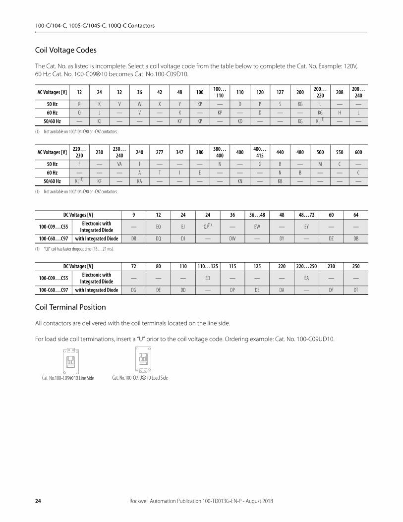
Coil Voltage Codes
The Cat. No. as listed is incomplete. Select a coil voltage code from the table below to complete the Cat. No. Example: 120V, 60 Hz: Cat. No. 100-C0910 becomes Cat. No.100-C09D10.
Coil Terminal Position
All contactors are delivered with the coil terminals located on the line side.
For load side coil terminations, insert a “U” prior to the coil voltage code. Ordering example: Cat. No. 100-C09UD10.
AC Voltages [V] 12 24 32 36 42 48 100 100…110 110 120 127 200 200…
220 208 208…240
50 Hz R K V W X Y KP — D P S KG L — —
60 Hz Q J — V — X — KP — D — — KG H L
50/60 Hz — KJ — — — KY KP — KD — — KG KL(1)
(1) Not available on 100/104-C90 or -C97 contactors.
— —
AC Voltages [V] 220…230 230 230…
240 240 277 347 380 380…400 400 400…
415 440 480 500 550 600
50 Hz F — VA T — — — N — G B — M C —
60 Hz — — — A T I E — — — N B — — C
50/60 Hz KL(1)
(1) Not available on 100/104-C90 or -C97 contactors.
KF — KA — — — — KN — KB — — — —
DC Voltages [V] 9 12 24 24 36 36…48 48 48…72 60 64
100-C09…C55 Electronic with Integrated Diode — EQ EJ QJ(1)
(1) “QJ” coil has faster dropout time (16…21 ms).
— EW — EY — —
100-C60…C97 with Integrated Diode DR DQ DJ — DW — DY — DZ DB
DC Voltages [V] 72 80 110 110…125 115 125 220 220…250 230 250
100-C09…C55 Electronic with Integrated Diode — — — ED — — — EA — —
100-C60…C97 with Integrated Diode DG DE DD — DP DS DA — DF DT
Cat. No.100-C0910 Line Side Cat. No.100-C09U10 Load Side
24 Rockwell Automation Publication 100-TD013G-EN-P - August 2018
100-C/104-C, 100S-C/104S-C, 100Q-C Contactors
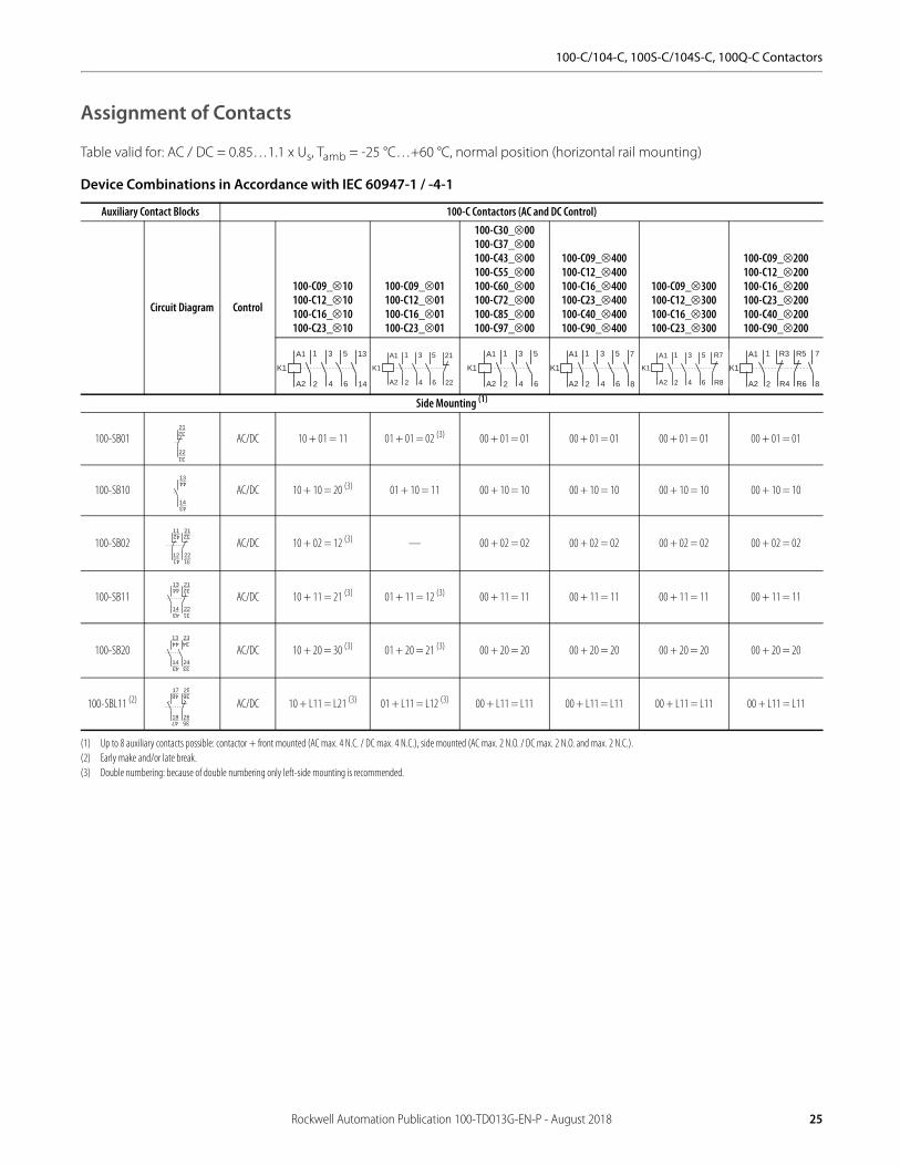
Assignment of Contacts
Table valid for: AC / DC = 0.85…1.1 x Us, Tamb = -25 °C…+60 °C, normal position (horizontal rail mounting)
Device Combinations in Accordance with IEC 60947-1 / -4-1
Auxiliary Contact Blocks 100-C Contactors (AC and DC Control)
Circuit Diagram Control
100-C09_10100-C12_10100-C16_10100-C23_10
100-C09_01100-C12_01100-C16_01100-C23_01
100-C30_00100-C37_00100-C43_00100-C55_00100-C60_00100-C72_00100-C85_00100-C97_00
100-C09_400100-C12_400100-C16_400100-C23_400100-C40_400100-C90_400
100-C09_300100-C12_300100-C16_300100-C23_300
100-C09_200100-C12_200100-C16_200100-C23_200100-C40_200100-C90_200
Side Mounting (1)
(1) Up to 8 auxiliary contacts possible: contactor + front mounted (AC max. 4 N.C. / DC max. 4 N.C.), side mounted (AC max. 2 N.O. / DC max. 2 N.O. and max. 2 N.C.).
100-SB01 AC/DC 10 + 01 = 11 01 + 01 = 02 (3)
(3) Double numbering: because of double numbering only left-side mounting is recommended.
00 + 01 = 01 00 + 01 = 01 00 + 01 = 01 00 + 01 = 01
100-SB10 AC/DC 10 + 10 = 20 (3) 01 + 10 = 11 00 + 10 = 10 00 + 10 = 10 00 + 10 = 10 00 + 10 = 10
100-SB02 AC/DC 10 + 02 = 12 (3) — 00 + 02 = 02 00 + 02 = 02 00 + 02 = 02 00 + 02 = 02
100-SB11 AC/DC 10 + 11 = 21 (3) 01 + 11 = 12 (3) 00 + 11 = 11 00 + 11 = 11 00 + 11 = 11 00 + 11 = 11
100-SB20 AC/DC 10 + 20 = 30 (3) 01 + 20 = 21 (3) 00 + 20 = 20 00 + 20 = 20 00 + 20 = 20 00 + 20 = 20
100-SBL11 (2)
(2) Early make and/or late break.
AC/DC 10 + L11 = L21 (3) 01 + L11 = L12 (3) 00 + L11 = L11 00 + L11 = L11 00 + L11 = L11 00 + L11 = L11
14
13
2
1
4
3
6
5A1
A2
K1
22
21
2
1
4
3
6
5A1
A2
K1
2
1
4
3
6
5A1
A2
K1
8
7
2
1
4
3
6
5A1
A2
K1
2
1
4
3
R8
R7A1
A2
K1
6
5
2
1
8
7
R6
R5A1
A2
K1
R4
R3
22
2132
31
14
1344
43
12
11
22
2142 32
314114
13
22
2144 32
3143
14
13
24
2344 34
3343
25361748
1847 2635
Rockwell Automation Publication 100-TD013G-EN-P - August 2018 25
100-C/104-C, 100S-C/104S-C, 100Q-C Contactors
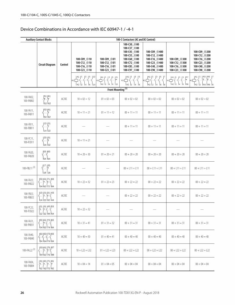
Device Combinations in Accordance with IEC 60947-1 / -4-1
Auxiliary Contact Blocks 100-C Contactors (AC and DC Control)
Circuit Diagram Control
100-C09_10100-C12_10100-C16_10100-C23_10
100-C09_01100-C12_01100-C16_01100-C23_01
100-C30_00100-C37_00100-C43_00100-C55_00100-C60_00100-C72_00100-C85_00100-C97_00
100-C09_400100-C12_400100-C16_400100-C23_400100-C40_400100-C90_400
100-C09_300100-C12_300100-C16_300100-C23_300
100-C09_200100-C12_200100-C16_200100-C23_200100-C40_200100-C90_200
Front Mounting (1)
100-FA02,100-FAB02
AC/DC 10 + 02 = 12 01 + 02 = 03 00 + 02 = 02 00 + 02 = 02 00 + 02 = 02 00 + 02 = 02
100-FA11,100-FAB11
AC/DC 10 + 11 = 21 01 + 11 = 12 00 + 11 = 11 00 + 11 = 11 00 + 11 = 11 00 + 11 = 11
100-FB11,100-FBB11
AC/DC — — 00 + 11 = 11 00 + 11 = 11 00 + 11 = 11 00 + 11 = 11
100-FC11,100-FCB11
AC/DC 10 + 11 = 21 — — — — —
100-FA20, 100-FAB20
AC/DC 10 + 20 = 30 01 + 20 = 21 00 + 20 = 20 00 + 20 = 20 00 + 20 = 20 00 + 20 = 20
100-FBL11 (2) AC/DC — — 00 + L11 = L11 00 + L11 = L11 00 + L11 = L11 00 + L11 = L11
100-FA22, 100-FAB22
AC/DC 10 + 22 = 32 01 + 22 = 23 00 + 22 = 22 00 + 22 = 22 00 + 22 = 22 00 + 22 = 22
100-FB22, 100-FBB22
AC/DC — — 00 + 22 = 22 00 + 22 = 22 00 + 22 = 22 00 + 22 = 22
100-FC22, 100-FCB22
AC/DC 10 + 22 = 32 — — — — —
100-FA31, 100-FAB31
AC/DC 10 + 31 = 41 01 + 31 = 32 00 + 31 = 31 00 + 31 = 31 00 + 31 = 31 00 + 31 = 31
100-FA40, 100-FAB40
AC/DC 10 + 40 = 50 01 + 40 = 41 00 + 40 = 40 00 + 40 = 40 00 + 40 = 40 00 + 40 = 40
100-FAL22 (2) AC/DC 10 + L22 = L32 01 + L22 = L23 00 + L22 = L22 00 + L22 = L22 00 + L22 = L22 00 + L22 = L22
100-FA04, 100-FAB04
AC/DC 10 + 04 = 14 01 + 04 = 05 00 + 04 = 04 00 + 04 = 04 00 + 04 = 04 00 + 04 = 04
14
13
2
1
4
3
6
5A1
A2
K1
22
21
2
1
4
3
6
5A1
A2
K1
2
1
4
3
6
5A1
A2
K1
8
7
2
1
4
3
6
5A1
A2
K1
2
1
4
3
R8
R7A1
A2
K1
6
5
2
1
8
7
R6
R5A1
A2
K1
R4
R3
51 61
6252
53 61
54 62
13 21
14 22
23 31
24 32
53 63
54 64
17 25
2618
53 61 71
7254 62
83
84
13 21 31
3214 22
43
44
433121
22 4432
53
54
53 61
54 62
73
74
83
84
53 63 73 83
8454 64 74
53 61 75
7654 62
87
88
51 61 71 81
8252 62 72
26 Rockwell Automation Publication 100-TD013G-EN-P - August 2018

100-C/104-C, 100S-C/104S-C, 100Q-C Contactors
100-FA13, 100-FAB13
AC/DC 10 + 13 = 23 01 + 13 = 14 00 + 13 = 13 00 + 13 = 13 00 + 13 = 13 00 + 13 = 13
100-FB02, 100-FBB02
AC/DC 10 + 02 = 12 01 + 02 = 03 00 + 02 = 02 00 + 02 = 02 00 + 02 = 02 00 + 02 = 02
100-FB20, 100-FBB20
AC/DC 10 + 20 = 30 01 + 20 = 21 00 + 20 = 20 00 + 20 = 20 00 + 20 = 20 00 + 20 = 20
100-FC31, 100-FCB31
AC/DC 10 + 31 = 41 01 + 31 = 32 00 + 31 = 31 00 + 31 = 31 00 + 31 = 31 00 + 31 = 31
(1) Up to 8 auxiliary contacts possible: contactor + front mounted (AC max. 4 N.C. / DC max. 4 N.C.), side mounted (AC max. 2 N.O. / DC max. 2 N.O. and max. 2 N.C.).(2) Early make and/or late break.
Auxiliary Contact Blocks 100-C Contactors (AC and DC Control)
Circuit Diagram Control
100-C09_10100-C12_10100-C16_10100-C23_10
100-C09_01100-C12_01100-C16_01100-C23_01
100-C30_00100-C37_00100-C43_00100-C55_00100-C60_00100-C72_00100-C85_00100-C97_00
100-C09_400100-C12_400100-C16_400100-C23_400100-C40_400100-C90_400
100-C09_300100-C12_300100-C16_300100-C23_300
100-C09_200100-C12_200100-C16_200100-C23_200100-C40_200100-C90_200
14
13
2
1
4
3
6
5A1
A2
K1
22
21
2
1
4
3
6
5A1
A2
K1
2
1
4
3
6
5A1
A2
K1
8
7
2
1
4
3
6
5A1
A2
K1
2
1
4
3
R8
R7A1
A2
K1
6
5
2
1
8
7
R6
R5A1
A2
K1
R4
R3
53 61 71 81
8254 62 72
11 21
2212
13 23
2414
23 31 43 53
5424 32 44
Rockwell Automation Publication 100-TD013G-EN-P - August 2018 27

100-C/104-C, 100S-C/104S-C, 100Q-C Contactors
Product Selection—100S-C/104S-C Safety Contactors• Mechanically linked N.C. auxiliary contacts• Front-mounted auxiliary contacts
– Gold bifurcated– Permanently fixed– Protective cover to prevent manual operation– Red contact housing for easy identification– “Mechanically Linked” or “Mirror Contact” symbol
• AC and DC operating coils• SUVA Third-Party certification
Bulletin 100S-C/104S-C safety contactors provide mechanically linked positively guided contacts, required in feedback circuits of modern safety applications. The mechanically linked N.C. auxiliary contacts will not change state when a power pole welds. In addition, the gold-plated bifurcated auxiliary contacts are ideally suited for low-energy applications or feedback control circuits with multiple series-connected N.C. auxiliary contacts.
3-Pole AC- and DC-operated Contactors
Coil voltage code and terminal position— see page 31.
Rated Operational Current Ie [A]Ratings for switching AC motors - AC-2, AC-3, AC-4 Auxiliary Contacts
Cat. No.(1) (2)
(1) For other contact configurations and full product details, please contact your local Rockwell Automation sales office or Allen-Bradley distributor.(2) If standard cross-stamped front-mount auxiliary contacts are required, remove the letter "B" before the letter "C" in the cat. no. Example: Cat. No. 100S-C09 05BC becomes Cat. No. 100S- C09 05C.
3-phase kW (50 Hz) Hp (60 Hz)
40 °C230V 400/415V 500V 690V
1-Phase 3-Phase
AC-3 AC-1 115V 230V 200V 230V 460V 575V N.O. N.C.
9 32 3 4 4 4 1/2 1-1/2 2 2 5 7-1/20 5 100S-C0905BC
1 4 100S-C0914BC
12 32 4 5.5 5.5 5.5 1/2 2 3 3 7-1/2 100 5 100S-C1205BC
1 4 100S-C1214BC
16 32 5.5 7.5 7.5 7.5 1 3 5 5 10 150 5 100S-C1605BC
1 4 100S-C1614BC
23 32 7.5 11 13 10 2 3 5 7-1/2 15 150 5 100S-C2305BC
1 4 100S-C2314BC
30 65 10 15 15 15 2 5 7-1/2 10 20 250 4 100S-C3004BC
1 4 100S-C3014BC
37 65 11 18.5/20 20 18.5 3 5 10 10 25 300 4 100S-C3704BC
1 4 100S-C3714BC
43 85 13 22 25 22 3 7-1/2 10 15 30 300 4 100S-C4304BC
1 4 100S-C4314BC
55 85 15 30 30 30 5 10 15 20 40 400 4 100S-C5504BC
1 4 100S-C5514BC
60 100 18.5 32 37 32 5 10 15 20 40 500 4 100S-C6004BC(3)
(3) Front- and side-mount auxiliary contacts on Cat. Nos. 100S-C60…C97 conform to mirror contact performance only.
1 4 100S-C6014BC(3)
72 100 22 40 45 40 5 15 20 25 50 600 4 100S-C7204BC(3)
1 4 100S-C7214BC(3)
85 100 25 45 55 45 7-1/2 15 25 30 60 600 4 100S-C8504BC(3)
1 4 100S-C8514BC(3)
97 130 30 55 55 55 10 15 30 30 75 750 4 100S-C9704BC(3)
1 4 100S-C9714BC(3)
100S-C Safety Contactor 104S-C Reversing Safety Contactor
28 Rockwell Automation Publication 100-TD013G-EN-P - August 2018

100-C/104-C, 100S-C/104S-C, 100Q-C Contactors
4-Pole AC- and DC-operated Contactors
Coil voltage code and terminal position— see page 31.
Ie [A]Ratings for Switching AC Motors
Contact Configuration
Cat. No.(1) (2)
(1) For other contact configurations and full product details, please contact your local Rockwell Automation sales office or Allen-Bradley distributor.(2) If standard cross-stamped front-mount auxiliary contacts are required, remove the letter "B" before the letter "C" in the cat. no. Example: Cat. No. 100S-C09404BC becomes Cat. No. 100S- C09 404C.
AC-2, AC-3, AC-4Hp (60 Hz)
3-Phase kW (50 Hz)(3)
(3) Three-phase ratings only apply to contactors with at least three N.O. power poles.
Main Pole Auxiliary Contacts
AC-3 AC-1 230V 400V/415V 500V 690V
1-Phase 3-Phase(3)
115V 230V 200V 230V 460V 575V
9 32 3 4 4 4 1/2 1-1/2 2 2 5 7-1/2N.O. N.C. N.O. N.C. 100S-C09404BC
3 1 0 4 100S-C09304BC
12 32 4 5.5 5.5 5.5 1/2 2 3 3 7-1/2 104 0 0 4 100S-C12404BC
3 1 0 4 100S-C12304BC
16 32 5.5 7.5 7.5 7.5 1 3 5 5 10 154 0 0 4 100S-C16404BC
3 1 0 4 100S-C16304BC
23 32 7.5 11 13 10 2 3 5 7-1/2 15 154 0 0 4 100S-C23404BC
3 1 0 4 100S-C23304BC
Rockwell Automation Publication 100-TD013G-EN-P - August 2018 29
100-C/104-C, 100S-C/104S-C, 100Q-C Contactors
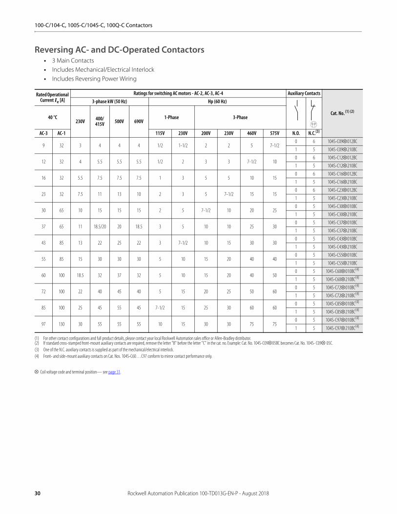
Reversing AC- and DC-Operated Contactors• 3 Main Contacts• Includes Mechanical/Electrical Interlock• Includes Reversing Power Wiring
Coil voltage code and terminal position— see page 31.
Rated Operational Current Ie [A]
Ratings for switching AC motors - AC-2, AC-3, AC-4 Auxiliary Contacts
Cat. No.(1) (2)
(1) For other contact configurations and full product details, please contact your local Rockwell Automation sales office or Allen-Bradley distributor.(2) If standard cross-stamped front-mount auxiliary contacts are required, remove the letter "B" before the letter "C" in the cat. no. Example: Cat. No. 104S-C0905BC becomes Cat. No. 104S- C09 05C.
3-phase kW (50 Hz) Hp (60 Hz)
40 °C230V 400/
415V 500V 690V1-Phase 3-Phase
AC-3 AC-1 115V 230V 200V 230V 460V 575V N.O. N.C.(3)
(3) One of the N.C. auxiliary contacts is supplied as part of the mechanical/electrical interlock.
9 32 3 4 4 4 1/2 1-1/2 2 2 5 7-1/20 6 104S-C09012BC
1 5 104S-C09210BC
12 32 4 5.5 5.5 5.5 1/2 2 3 3 7-1/2 100 6 104S-C12012BC
1 5 104S-C12210BC
16 32 5.5 7.5 7.5 7.5 1 3 5 5 10 150 6 104S-C16012BC
1 5 104S-C16210BC
23 32 7.5 11 13 10 2 3 5 7-1/2 15 150 6 104S-C23012BC
1 5 104S-C23210BC
30 65 10 15 15 15 2 5 7-1/2 10 20 250 5 104S-C30010BC
1 5 104S-C30210BC
37 65 11 18.5/20 20 18.5 3 5 10 10 25 300 5 104S-C37010BC
1 5 104S-C37210BC
43 85 13 22 25 22 3 7-1/2 10 15 30 300 5 104S-C43010BC
1 5 104S-C43210BC
55 85 15 30 30 30 5 10 15 20 40 400 5 104S-C55010BC
1 5 104S-C55210BC
60 100 18.5 32 37 32 5 10 15 20 40 500 5 104S-C60010BC(4)
(4) Front- and side-mount auxiliary contacts on Cat. Nos. 104S-C60…C97 conform to mirror contact performance only.
1 5 104S-C60210BC(4)
72 100 22 40 45 40 5 15 20 25 50 600 5 104S-C72010BC(4)
1 5 104S-C72210BC(4)
85 100 25 45 55 45 7-1/2 15 25 30 60 600 5 104S-C85010BC(4)
1 5 104S-C85210BC(4)
97 130 30 55 55 55 10 15 30 30 75 750 5 104S-C97010BC(4)
1 5 104S-C97210BC(4)
30 Rockwell Automation Publication 100-TD013G-EN-P - August 2018
100-C/104-C, 100S-C/104S-C, 100Q-C Contactors
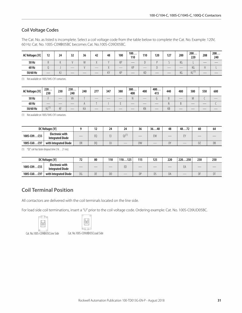
Coil Voltage Codes
The Cat. No. as listed is incomplete. Select a coil voltage code from the table below to complete the Cat. No. Example: 120V, 60 Hz: Cat. No. 100S-C0905BC becomes Cat. No.100S-C09D05BC.
Coil Terminal Position
All contactors are delivered with the coil terminals located on the line side.
For load side coil terminations, insert a “U” prior to the coil voltage code. Ordering example: Cat. No. 100S-C09UD05BC.
AC Voltages [V] 12 24 32 36 42 48 100 100…110 110 120 127 200 200…
220 208 208…240
50 Hz R K V W X Y KP — D P S KG L — —
60 Hz Q J — V — X — KP — D — — KG H L
50/60 Hz — KJ — — — KY KP — KD — — KG KL(1)
(1) Not available on 100S/104S-C97 contactors.
— —
AC Voltages [V] 220…230 230 230…
240 240 277 347 380 380…400 400 400…
415 440 480 500 550 600
50 Hz F — VA T — — — N — G B — M C —
60 Hz — — — A T I E — — — N B — — C
50/60 Hz KL(1)
(1) Not available on 100S/104S-C97 contactors.
KF — KA — — — — KN — KB — — — —
DC Voltages [V] 9 12 24 24 36 36…48 48 48…72 60 64
100S-C09…C55 Electronic with Integrated Diode — EQ EJ QJ(1)
(1) “QJ” coil has faster dropout time (16…21 ms).
— EW — EY — —
100S-C60…C97 with Integrated Diode DR DQ DJ — DW — DY — DZ DB
DC Voltages [V] 72 80 110 110…125 115 125 220 220…250 230 250
100S-C09…C55 Electronic with Integrated Diode — — — ED — — — EA — —
100S-C60…C97 with Integrated Diode DG DE DD — DP DS DA — DF DT
Cat. No.100S-C0905CLine Side Cat. No.100S-C09U05CLoad Side
Rockwell Automation Publication 100-TD013G-EN-P - August 2018 31
100-C/104-C, 100S-C/104S-C, 100Q-C Contactors
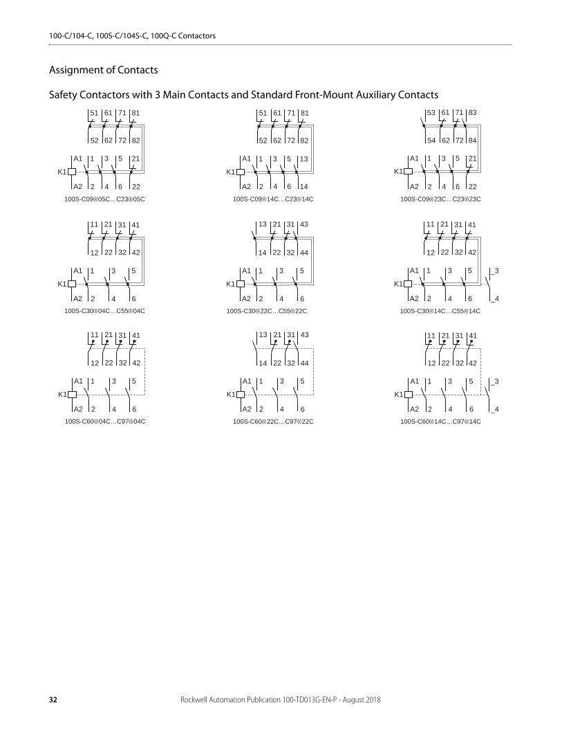
Assignment of Contacts
Safety Contactors with 3 Main Contacts and Standard Front-Mount Auxiliary Contacts
K1
A2
A1
K1
A2
A1
K1
A2
A1
82
81
52
51
62
61
72
71
22
21
2
1
4
3
6
5
100S-C0905C…C2305C
82
81
52
51
62
61
72
71
2
1
4
3
6
5
14
13
42
41
12
11
22
21
32
31
2
1
4
3
6
5
2
1
4
3
6
5
22
21
32
31
14
13
44
43
22
21
62
61
72
71
2
1
4
3
6
5
54
53
84
83
K1
A2
A1
100S-C0914C…C2314C 100S-C0923C…C2323C
K1
A2
A1
100S-C3004C…C5504C 100S-C3022C…C5522C 100S-C3014C…C5514C
_4
_3
K1
A2
A1
42
41
12
11
22
21
32
31
2
1
4
3
6
5
K1
A2
A1
K1
A2
A1
42
41
12
11
22
21
32
31
2
1
4
3
6
5
2
1
4
3
6
5
22
21
32
31
14
13
44
43
42
41
12
11
22
21
32
31
2
1
4
3
6
5
_4
_3
K1
A2
A1
100S-C6004C…C9704C 100S-C6022C…C9722C 100S-C6014C…C9714C
32 Rockwell Automation Publication 100-TD013G-EN-P - August 2018

100-C/104-C, 100S-C/104S-C, 100Q-C Contactors
Safety Contactors with 4 Main Contacts and Standard Front-Mount Auxiliary Contacts
K1
A2
A1
42
41
12
11
22
21
32
31
R8
R7
2
1
4
3
6
5
R8
R7
42
41
12
11
22
21
32
31
8
7
2
1
4
3
6
5
22
21
32
31
8
7
2
1
4
3
6
5
14
13
44
43
22
21
32
31
2
1
4
3
6
5
14
13
44
43
K1
A2
A1
100S-C09⊗404C…C23⊗404C 100S-C09⊗304C…C23⊗304C
K1
A2
A1
K1
A2
A1
100S-C09⊗322C…C23⊗322C100S-C09⊗422C…C23⊗422C
Rockwell Automation Publication 100-TD013G-EN-P - August 2018 33
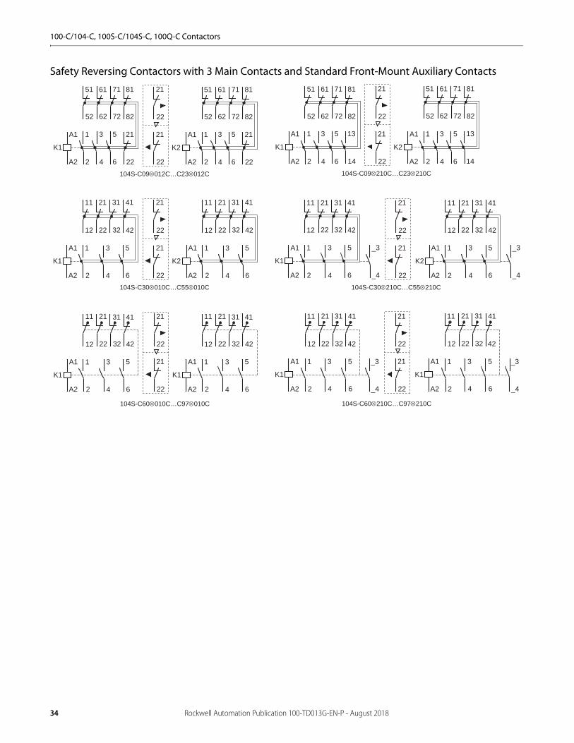
100-C/104-C, 100S-C/104S-C, 100Q-C Contactors
Safety Reversing Contactors with 3 Main Contacts and Standard Front-Mount Auxiliary Contacts
22
21
22
21
82
81
52
51
62
61
72
71
22
21
2
1
4
3
6
5
104S-C09012C…C23012C
K1
A2
A1
82
81
52
51
62
61
72
71
22
21
2
1
4
3
6
5
K2
A2
A1
22
21
22
21
104S-C30010C…C55010C
K1
A2
A1
42
41
12
11
22
21
32
31
2
1
4
3
6
5
K2
A2
A1
2
1
4
3
6
5
22
21
22
21
2
1
4
3
6
5
104S-C09210C…C23210C
K1
A2
A1
2
1
4
3
6
5
K2
A2
A1
14
13
14
13
22
21
22
21
42
41
12
11
22
21
32
31
2
1
4
3
6
5
104S-C30210C…C55210C
K1
A2
A1
42
41
12
11
22
21
32
31
2
1
4
3
6
5
K2
A2
A1
_4
_3
_4
_3
22
21
22
21
104S-C60010C…C97010C
K1
A2
A1
42
41
12
11
22
21
32
31
2
1
4
3
6
5
K1
A2
A1
42
41
12
11
22
21
32
31
2
1
4
3
6
5
104S-C60210C…C97210C
22
21
22
21
2
1
4
3
6
5
_4
_3
K1
A2
A1
42
41
12
11
22
21
32
31
2
1
4
3
6
5
_4
_3
K1
A2
A1
42
41
12
11
22
21
32
31
42
41
12
11
22
21
32
31
82
81
52
51
62
61
72
71
82
81
52
51
62
61
72
71
34 Rockwell Automation Publication 100-TD013G-EN-P - August 2018
100-C/104-C, 100S-C/104S-C, 100Q-C Contactors
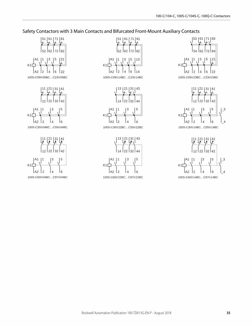
Safety Contactors with 3 Main Contacts and Bifurcated Front-Mount Auxiliary Contacts
K1
A2
A1
K1
A2
A1
K1
A2
A1
82
81
52
51
62
61
72
71
22
21
2
1
4
3
6
5
100S-C0905BC…C2305BC
82
81
52
51
62
61
72
71
2
1
4
3
6
5
14
13
42
41
12
11
22
21
32
31
2
1
4
3
6
5
2
1
4
3
6
5
22
21
32
31
14
13
44
43
22
21
62
61
72
71
2
1
4
3
6
5
54
53
84
83
_4
_3
K1
A2
A1
100S-C0914BC…C2314BC 100S-C0923BC…C2323BC
K1
A2
A1
100S-C3004BC…C5504BC 100S-C3022BC…C5522BC 100S-C3014BC…C5514BC
K1
A2
A1
K1
A2
A1
42
41
12
11
22
21
32
31
2
1
4
3
6
5
2
1
4
3
6
5
22
21
32
31
14
13
44
43
100S-C6004BC…C9704BC 100S-C6022BC…C9722BC 100S-C6014BC…C9714BC
K1
A2
A1
42
41
12
11
22
21
32
31
2
1
4
3
6
5
42
41
12
11
22
21
32
31
2
1
4
3
6
5
_4
_3
K1
A2
A1
Rockwell Automation Publication 100-TD013G-EN-P - August 2018 35

100-C/104-C, 100S-C/104S-C, 100Q-C Contactors
Safety Contactors with 4 Main Contacts and Bifurcated Front-Mount Auxiliary Contacts
K1
A2
A1
42
41
12
11
22
21
32
31
R8
R7
2
1
4
3
6
5
R8
R7
42
41
12
11
22
21
32
31
8
7
2
1
4
3
6
5
22
21
32
31
8
7
2
1
4
3
6
5
14
13
44
43
22
21
32
31
2
1
4
3
6
5
14
13
44
43
K1
A2
A1
100S-C09⊗404BC…C23⊗404BC 100S-C09⊗304BC…C23⊗304BC
K1
A2
A1
K1
A2
A1
100S-C09⊗322BC…C23⊗322BC100S-C09⊗422BC…C23⊗422BC
36 Rockwell Automation Publication 100-TD013G-EN-P - August 2018
100-C/104-C, 100S-C/104S-C, 100Q-C Contactors
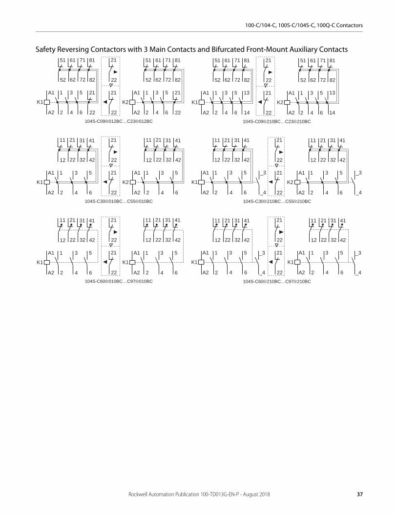
Safety Reversing Contactors with 3 Main Contacts and Bifurcated Front-Mount Auxiliary Contacts
22
21
22
21
82
81
52
51
62
61
72
71
22
21
2
1
4
3
6
5
104S-C09012BC…C23012BC
K1
A2
A1
82
81
52
51
62
61
72
71
22
21
2
1
4
3
6
5
K2
A2
A1
22
21
22
21
104S-C30010BC…C55010BC
K1
A2
A1
42
41
12
11
22
21
32
31
2
1
4
3
6
5
K2
A2
A1
42
41
12
11
22
21
32
31
2
1
4
3
6
5
22
21
22
21
82
81
52
51
62
61
72
71
2
1
4
3
6
5
104S-C09210BC…C23210BC
K1
A2
A1
82
81
52
51
62
61
72
71
2
1
4
3
6
5
K2
A2
A1
14
13
14
13
22
21
22
21
42
41
12
11
22
21
32
31
2
1
4
3
6
5
104S-C30210BC…C55210BC
K1
A2
A1
42
41
12
11
22
21
32
31
2
1
4
3
6
5
K2
A2
A1
_4
_3
_4
_3
22
21
22
21
104S-C60010BC…C97010BC
K1
A2
A1
42
41
12
11
22
21
32
31
2
1
4
3
6
5
K1
A2
A1
42
41
12
11
22
21
32
31
2
1
4
3
6
5
104S-C60210BC…C97210BC
42
41
12
11
22
21
32
31
2
1
4
3
6
5
_4
_3
K1
A2
A1
42
41
12
11
22
21
32
31
2
1
4
3
6
5
_4
_3
K1
A2
A1
22
21
22
21
Rockwell Automation Publication 100-TD013G-EN-P - August 2018 37
100-C/104-C, 100S-C/104S-C, 100Q-C Contactors
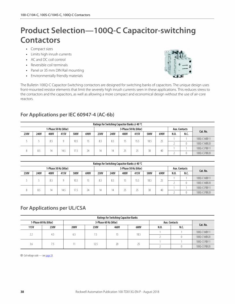
Product Selection—100Q-C Capacitor-switching Contactors
• Compact sizes• Limits high inrush currents• AC and DC coil control• Reversible coil terminals• Panel or 35 mm DIN Rail mounting• Environmentally friendly materials
The Bulletin 100Q-C Capacitor-Switching contactors are designed for switching banks of capacitors. The unique design uses front-mounted resistor elements that limit the severely high inrush currents seen in these applications. This reduces stress to the contactors and the capacitors, as well as allowing a more compact and economical design without the use of air-core reactors.
For Applications per IEC 60947-4 (AC-6b)
For Applications per UL/CSA
Coil voltage code — see page 39.
Ratings for Switching Capacitor Banks @ 40 °C1-Phase 50 Hz (kVar) 3-Phase 50 Hz (kVar) Aux. Contacts
Cat. No.230V 240V 400V 415V 500V 690V 230V 240V 400V 415V 500V 690V N.O. N.C.
5 5 8.5 9 10.5 15 8.5 8.5 15 15.5 18.5 251 1 100Q-C1611
2 0 100Q-C1620
8 8.5 14 14.5 17.5 24 14 14 25 25 30 401 1 100Q-C3711
2 0 100Q-C3720
Ratings for Switching Capacitor Banks1-Phase 60 Hz (kVar) 3-Phase 60 Hz (kVar) Aux. Contacts
Cat. No.115V 230V 200V 230V 460V 600V N.O. N.C.
2.2 4.5 6.5 7.5 15 18.51 1 100Q-C1611
2 0 100Q-C1620
3.6 7.5 11 12.5 20 251 1 100Q-C3711
2 0 100Q-C3720
38 Rockwell Automation Publication 100-TD013G-EN-P - August 2018

100-C/104-C, 100S-C/104S-C, 100Q-C Contactors
Coil Voltage Codes
The Cat. No. as listed is incomplete. Select a coil voltage code from the table below to complete the Cat. No. Example: 120V, 60 Hz: Cat. No. 100Q-C1611 becomes Cat. No.100Q-C16D11.
Maximum Operational Rates• 100Q-C16 200 operations/hour• 100Q-C37 100 operations/hour
AC Voltages [V] 12 24 32 36 42 48 100 100…110
110 120 127 200 200…220
208 208…240
50 Hz R K V W X Y KP — D P S KG L — —
60 Hz Q J — V — X — KP — D — — KG H L
50/60 Hz — KJ — — — KY KP — KD — — KG KL — —
AC Voltages [V] 220…230
230 230…240
240 277 347 380 380…400
400 400…415
440 480 500 550 600
50 Hz F — VA T — — — N — G B — M C —
60 Hz — — — A T I E — — — N B — — C
50/60 Hz KL KF — KA — — — — KN — KB — — — —
DC Voltages [V] 9 12 24 36 48 60 64 72Electronic with Integrated Diode — EQ EJ — — — — —
DC Voltages [V] 80 110 110…125 115 125 220 220…250 230 250Electronic with Integrated Diode — — ED — — — EA — —
Rockwell Automation Publication 100-TD013G-EN-P - August 2018 39

100-C/104-C, 100S-C/104S-C, 100Q-C Contactors
AccessoriesAuxiliary Contact Blocks
Description(1)
(1) Max. number of auxiliary contacts that may be mounted:AC and 24V DC electronic coil contactors—max. 4 N.O contacts on the front of the contactor, 2 N.O. contacts on the side, 4 N.C. front or side, 6 total. DC Coil contactors—max. 4 N.O. contacts on the front of the contactor or max. 2 N.O. contacts on the side, 4 N.C. front or side, 4 total.
Connection Diagrams For Use With
Cat. No.
N.O. N.C.Standard Auxiliary
Contact(2)
(2) For screwless terminals (front mount only), insert "CR" after the "100-" in the catalog number. Example: Cat. No. 100-FA02 becomes Cat. No. 100-CRFA02.
Bifurcated Auxiliary Contact
Auxiliary Contact Blocks for Front Mounting• 2- and 4-pole• Quick and easy mounting without tools• Electronic-compatible contacts down to 17V, 5mA• Mechanically linked performance between N.O. and N.C.
poles and to the main contactor poles (except for L types)
• Models with equal function with several terminal numbering choices
• 1L = Late break N.C. / early make N.O.• Bifurcated version for switching down to 5V, 3 mA also
available
\
0 2100-C all 100-FA02 100-FAB02
C3000...C9700 100-FB02 100-FBB02
1 1
100-C all 100-FA11 100-FAB11
C3000...C9700 100-FB11 100-FBB11
C0910...C2310 100-FC11 100-FCB11
2 0100-C all 100-FA20 100-FAB20
C3000...C9700 100-FB20 100-FBB20
1L 1L100-C all 100-FAL11 —
C3000...C9700 100-FBL11 —
0 4 100-C all 100-FA04 100-FAB04
1 3 100-C all 100-FA13 100-FAB13
2 2
100-C all 100-FA22 100-FAB22
C3000...C9700 100-FB22 100-FBB22
C0910...C2310 100-FC22 100-FCB22
3 1100-C all 100-FA31 100-FAB31
C0910...C2310 100-FC31 100-FCB31
4 0 100-C all 100-FA40 100-FAB40
1 + 1L 1+1L 100-C all 100-FAL22 —
Auxiliary Contact Blocks for Side Mounting without Sequence Terminal Designations• 1- and 2-pole• Two-way numbering for right or left mounting on the
contactor• Quick and easy mounting without tools• Electronic-compatible contacts down to 17V, 10 mA• Mirror contact performance to the main contactor poles• 1L = Late break N.C. / early make N.O.
0 1 100-C all 100-SA01 —
1 0 100-C all 100-SA10 —
0 2 100-C all 100-SA02 —
1 1 100-C all 100-SA11 —
2 0 100-C all 100-SA20 —
1L 1L 100-C all 100-SAL11 —
Auxiliary Contact Blocks for Side Mounting with Sequence Terminal Designations• 1- and 2-pole• Two-way numbering for right or left mounting on the
contactor• Quick and easy mounting without tools• Electronic-compatible contacts down to 17V, 10 mA• Mirror contact performance to the main contactor poles• 1L = Late break N.C. / early make N.O.
0 1 100-C 100-SB01 —
1 0 100-C(3)
(3) Double numbering—Left-side mounting only is recommended for Cat. No. 100-C09...100-C23 due to double numbering.
100-SB10 —
0 2 100-C(3) 100-SB02 —
1 1 100-C(3) 100-SB11 —
2 0 100-C(3) 100-SB20 —
1L 1L 100-C(3) 100-SBL11 —
40 Rockwell Automation Publication 100-TD013G-EN-P - August 2018
100-C/104-C, 100S-C/104S-C, 100Q-C Contactors
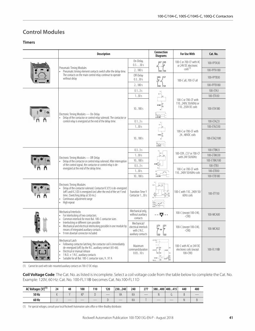
Control Modules
Timers
Coil Voltage Code: The Cat. No. as listed is incomplete. Select a coil voltage code from the table below to complete the Cat. No. Example: 120V, 60 Hz: Cat. No. 100-FL11 becomes Cat. No.100-FL11D
Description Connection Diagrams For Use With Cat. No.
Pneumatic Timing Modules• Pneumatic timing element contacts switch after the delay time.
The contacts on the main control relay continue to operate without delay
On-Delay,0.3…30 s
100-C or 700-CF with AC or 24V DC electronic
coils(1)
(1) Cannot be used with side-mounted auxiliary contacts on 700-CF DC relays.
100-FPTA30
2...180 s 100-FPTA180
Off-Delay0.3...30 s 100-C all, 700-CF all
100-FPTB30
2...180 s 100-FPTB180
Electronic Timing Modules — On-Delay• Delay of the contactor or control relay solenoid. The contactor or
control relay is energized at the end of the delay time.
0.1...3 s
100-C or 700-CF with 110...240V, 50/60Hz or
110...250V DC coils
100-ETA3
1...30 s 100-ETA30
10...180 s 100-ETA180
0.1...3 s
100-C or 700-CF with 24...48VDC coils
100-ETAZJ3
1...30 s 100-ETAZJ30
10...180 s 100-ETAZJ180
Electronic Timing Modules — Off-Delay• Delay of the contactor or control relay solenoid. After interruption
of the control signal, the contactor or control relay is de-energized at the end of the delay time.
0.3...3 s 100-C09...C37 or 700-CF
with 24V 50/60Hz
100-ETBKJ3
1...30 s 100-ETBKJ30
10...180 s 100-ETBKJ180
0.3...3 s100-C or 700-CF with
110...240V 50/60Hz coils
100-ETB3
1...30 s 100-ETB30
10...180 s 100-ETB180
Electronic Timing Modules • Delay of the contactor solenoid. Contactor K 3(Y) is de-energized
(off ) and K 2 (D) is energized (on) after the end of the set Y end time. (Switching delay at 50 ms.)
• Continuous adjustment range• High repeat
Transition Time Y Contactor 1...30 s
100-C with 110...240V 50/60Hz coils 100-ETY30
Mechanical Interlocks• For interlocking of two contactors.• Common interlock for most Bul. 100-C contactor sizes• Interlocking or different sizes possible • Mechanical and electrical interlocking possible in one module by
means of integrated auxiliary contacts • 9 mm dovetail connector included
Mechanical only, without auxiliary
contacts
100-C (except 100-C40, -C90) 100-MCA00
Mechanical/ electrical interlock
with 2 N.C. auxiliary contacts
100-C (except 100-C40, -C90) 100-MCA02
Mechanical Latch• Following contactor latching, the contactor coil is immediately
de-energized (off) by the N.C. auxiliary contact (65-66).• Electrical or manual release• 1 N.O. + 1 N.C. auxiliary contacts• Suitable for all Bul. 100-C contactor sizes, 9...97 A
Maximum command duration
0.03...10 s
100-C with AC or 24V DC electronic coils (except
100-C90)100-FL11
AC Voltages [V](1)
(1) For special voltages, consult your local Rockwell Automation sales office or Allen-Bradley distributor.
24 48 100 110 120 230...240 240 277 380...400 400...415 440 480
50 Hz K Y KP D — VA KA — N G B —
60 Hz J — — — D — KA T — — N B
Rockwell Automation Publication 100-TD013G-EN-P - August 2018 41

100-C/104-C, 100S-C/104S-C, 100Q-C Contactors
Control Modules (For 100-C09...C97 contactors), Continued
Assembly Components (For 100-C09...C97 contactors)
Description Voltage Range Connection Diagrams For Use With Cat. No.
DC Interface (Electronic)• Interface between the DC control signal (PLC) and the AC
operating mechanism of the contactor.• Requires no additional surge suppression on the relay coils.
Input: 12V DCOutput: 110...240V AC
100-C with AC coils 110...240V AC
100-JE12
Input: 18...30V DCOutput: 110...240V AC
100-JE
Input: 48V DCOutput: 110...240V AC
100-JE48
Surge Suppressors • For limitation of coil switching
transients.• Plug-in, coil mounted.• Suitable for 100-C contactor
sizes, 9...97 A.• RC, varistor, and diode
versions.
RC ModuleAC operating mechanism
24...48V AC, 50/60 Hz
100-C with Coils
100-FSC48(1)
(1) For screwless terminals, insert “CR” after the “100-” in the catalog number. Example: Cat No. 100-FSC48 becomes Cat. No.-CRFSC48.
110...280V AC, 50/60 Hz 100-FSC280(1)
380...480V AC, 50/60 Hz 100-FSC480(1)
Varistor ModuleAC/DC operating mechanism
12...55V AC, 12...77V DC
100-C with AC coils or 100-C09...-C43 with DC
coils
100-FSV55(1)
56...136V AC/78...180V DC 100-FSV136(1)
137...277V AC/ 181...350V DC 100-FSV277(1)
278...575V AC 100-FSV575(1)
Diode ModuleDC operating mechanism
1...30 s10...180 s
100-C09...-C43 with DC coils 100-FSD250(1)
Description For Use With Pkg. Qty. Cat. No.Dovetail Connectors• For use in contactor and starter assemblies• Single Connector — 0 mm spacing
100-C
10 100-S0
Dovetail Connectors• For use in contactor and starter assemblies• Single Connector — 9mm spacing
10
Protective Covers• Provides protection against unintended manual operation• For contactors and front-mounted auxiliary contacts, pneumatic timers, and latches
100-C all 1 100-SCCA
100-FA, -FB, -FC, -FP, -FL 10 100-SCFA
Reversing Power Wiring Kits• For reversing connection with a solid-state or thermal overload relay
100-C09...C23 1 105-PW23
100-C30...C37 1 105-PW37
100-C43…C55 1 105-PW55
100-C60...C97 1 105-PW85
DIN (#3) symmetrical hat rail• 35 x 7.5 x 1 m
140M-D140M-F100-C all
10 199-DR1
42 Rockwell Automation Publication 100-TD013G-EN-P - August 2018
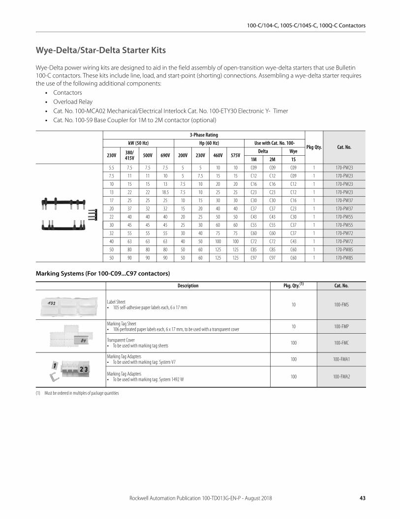
100-C/104-C, 100S-C/104S-C, 100Q-C Contactors
Wye-Delta/Star-Delta Starter Kits
Wye-Delta power wiring kits are designed to aid in the field assembly of open-transition wye-delta starters that use Bulletin 100-C contactors. These kits include line, load, and start-point (shorting) connections. Assembling a wye-delta starter requires the use of the following additional components:
• Contactors • Overload Relay• Cat. No. 100-MCA02 Mechanical/Electrical Interlock Cat. No. 100-ETY30 Electronic Y- Timer• Cat. No. 100-S9 Base Coupler for 1M to 2M contactor (optional)
Marking Systems (For 100-C09...C97 contactors)
3-Phase Rating
Pkg Qty. Cat. No.kW (50 Hz) Hp (60 Hz) Use with Cat. No. 100-
230V 380/415V 500V 690V 200V 230V 460V 575V
Delta Wye1M 2M 1S
5.5 7.5 7.5 7.5 5 5 10 10 C09 C09 C09 1 170-PW23
7.5 11 11 10 5 7.5 15 15 C12 C12 C09 1 170-PW23
10 15 15 13 7.5 10 20 20 C16 C16 C12 1 170-PW23
13 22 22 18.5 7.5 10 25 25 C23 C23 C12 1 170-PW23
17 25 25 25 10 15 30 30 C30 C30 C16 1 170-PW37
20 37 32 32 15 20 40 40 C37 C37 C23 1 170-PW37
22 40 40 40 20 25 50 50 C43 C43 C30 1 170-PW55
30 45 45 45 25 30 60 60 C55 C55 C37 1 170-PW55
32 55 55 55 30 40 75 75 C60 C60 C37 1 170-PW72
40 63 63 63 40 50 100 100 C72 C72 C43 1 170-PW72
50 80 80 80 50 60 125 125 C85 C85 C60 1 170-PW85
50 90 90 90 50 60 125 125 C97 C97 C60 1 170-PW85
Description Pkg. Qty.(1)
(1) Must be ordered in multiples of package quantities
Cat. No.
Label Sheet• 105 self-adhesive paper labels each, 6 x 17 mm 10 100-FMS
Marking Tag Sheet• 106 perforated paper labels each, 6 x 17 mm, to be used with a transparent cover 10 100-FMP
Transparent Cover• To be used with marking tag sheets 100 100-FMC
Marking Tag Adapters• To be used with marking tag: System V7 100 100-FMA1
Marking Tag Adapters• To be used with marking tag: System 1492 W 100 100-FMA2
Rockwell Automation Publication 100-TD013G-EN-P - August 2018 43
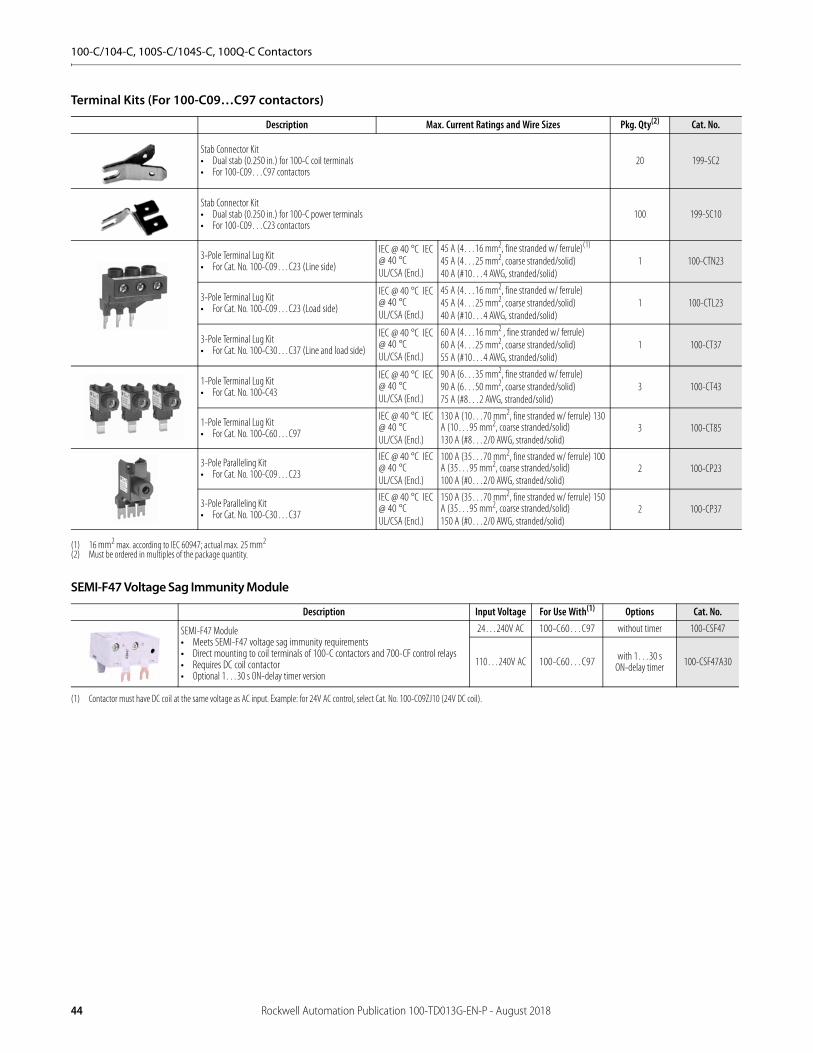
100-C/104-C, 100S-C/104S-C, 100Q-C Contactors
Terminal Kits (For 100-C09…C97 contactors)
SEMI-F47 Voltage Sag Immunity Module
Description Max. Current Ratings and Wire Sizes Pkg. Qty(2)
(2) Must be ordered in multiples of the package quantity.
Cat. No.
Stab Connector Kit• Dual stab (0.250 in.) for 100-C coil terminals• For 100-C09…C97 contactors
20 199-SC2
Stab Connector Kit• Dual stab (0.250 in.) for 100-C power terminals• For 100-C09…C23 contactors
100 199-SC10
3-Pole Terminal Lug Kit• For Cat. No. 100-C09…C23 (Line side)
IEC @ 40 °C IEC @ 40 °CUL/CSA (Encl.)
45 A (4…16 mm2, fine stranded w/ ferrule)(1)
45 A (4…25 mm2, coarse stranded/solid)40 A (#10…4 AWG, stranded/solid)
(1) 16 mm2 max. according to IEC 60947; actual max. 25 mm2
1 100-CTN23
3-Pole Terminal Lug Kit• For Cat. No. 100-C09…C23 (Load side)
IEC @ 40 °C IEC @ 40 °CUL/CSA (Encl.)
45 A (4…16 mm2, fine stranded w/ ferrule) 45 A (4…25 mm2, coarse stranded/solid)40 A (#10…4 AWG, stranded/solid)
1 100-CTL23
3-Pole Terminal Lug Kit• For Cat. No. 100-C30…C37 (Line and load side)
IEC @ 40 °C IEC @ 40 °CUL/CSA (Encl.)
60 A (4…16 mm2 , fine stranded w/ ferrule) 60 A (4…25 mm2, coarse stranded/solid)55 A (#10…4 AWG, stranded/solid)
1 100-CT37
1-Pole Terminal Lug Kit• For Cat. No. 100-C43
IEC @ 40 °C IEC @ 40 °CUL/CSA (Encl.)
90 A (6…35 mm2, fine stranded w/ ferrule) 90 A (6…50 mm2, coarse stranded/solid) 75 A (#8…2 AWG, stranded/solid)
3 100-CT43
1-Pole Terminal Lug Kit• For Cat. No. 100-C60…C97
IEC @ 40 °C IEC @ 40 °CUL/CSA (Encl.)
130 A (10…70 mm2, fine stranded w/ ferrule) 130 A (10…95 mm2, coarse stranded/solid) 130 A (#8…2/0 AWG, stranded/solid)
3 100-CT85
3-Pole Paralleling Kit• For Cat. No. 100-C09…C23
IEC @ 40 °C IEC @ 40 °CUL/CSA (Encl.)
100 A (35…70 mm2, fine stranded w/ ferrule) 100 A (35…95 mm2, coarse stranded/solid) 100 A (#0…2/0 AWG, stranded/solid)
2 100-CP23
3-Pole Paralleling Kit• For Cat. No. 100-C30…C37
IEC @ 40 °C IEC @ 40 °CUL/CSA (Encl.)
150 A (35…70 mm2, fine stranded w/ ferrule) 150 A (35…95 mm2, coarse stranded/solid) 150 A (#0…2/0 AWG, stranded/solid)
2 100-CP37
Description Input Voltage For Use With(1)
(1) Contactor must have DC coil at the same voltage as AC input. Example: for 24V AC control, select Cat. No. 100-C09ZJ10 (24V DC coil).
Options Cat. No.
SEMI-F47 Module• Meets SEMI-F47 voltage sag immunity requirements• Direct mounting to coil terminals of 100-C contactors and 700-CF control relays• Requires DC coil contactor• Optional 1…30 s ON-delay timer version
24…240V AC 100-C60…C97 without timer 100-CSF47
110…240V AC 100-C60…C97 with 1…30 s ON-delay timer 100-CSF47A30
44 Rockwell Automation Publication 100-TD013G-EN-P - August 2018
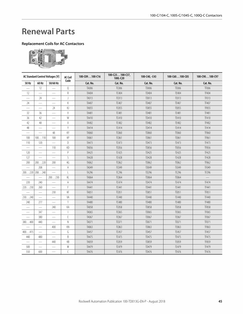
100-C/104-C, 100S-C/104S-C, 100Q-C Contactors
Renewal PartsReplacement Coils for AC Contactors
AC Standard Control Voltages [V] AC Coil Code
100-C09…100-C16 100-C23…100-C37, 100L-C20 100-C40, -C43 100-C60…100-C85 100-C90…100-C97
50 Hz 60 Hz 50/60 Hz Cat. No. Cat. No. Cat. No. Cat. No. Cat. No.— 12 — Q TA006 TC006 TD006 TE006 TF006
12 — — R TA404 TC404 TD404 TE404 TF404
— 24 — J TA013 TC013 TD013 TE013 TF013
24 — — K TA407 TC407 TD407 TE407 TF407
— — 24 KJ TA855 TC855 TD855 TE855 TF855
32 36 — V TA481 TC481 TD481 TE481 TF481
36 42 — W TA410 TC410 TD410 TE410 TF410
42 48 — X TA482 TC482 TD482 TE482 TF482
48 — — Y TA414 TC414 TD414 TE414 TF414
— — 48 KY TA860 TC860 TD860 TE860 TF860
100 100…110 100 KP TA861 TC861 TD861 TE861 TF861
110 120 — D TA473 TC473 TD473 TE473 TF473
— — 110 KD TA856 TC856 TD856 TE856 TF856
120 — — P TA425 TC425 TD425 TE425 TF425
127 — — S TA428 TC428 TD428 TE428 TF428
200 200…220 200 KG TA862 TC862 TD862 TE862 TF862
— 208 — H TA049 TC049 TD049 TE049 TF049
200…220 208…240 — L TA296 TC296 TD296 TE296 TF296
— — 200…230 KL TA864 TC864 TD864 TE864 —
220 240 — A TA474 TC474 TD474 TE474 TF474
220…230 260 — F TA441 TC441 TD441 TE441 TF441
— — 230 KF TA851 TC851 TD851 TE851 TF851
230…240 — — VA TA440 TC440 TD440 TE440 TF440
240 277 — T TA480 TC480 TD480 TE480 TF480
— — 240 KA TA858 TC858 TD858 TE858 TF858
— 347 — I TA065 TC065 TD065 TE065 TF065
— 380 — E TA067 TC067 TD067 TE067 TF067
380…400 440 — N TA071 TC071 TD071 TE071 TF071
— — 400 KN TA863 TC863 TD863 TE863 TF863
400…415 — — G TA457 TC457 TD457 TE457 TF457
440 480 — B TA475 TC475 TD475 TE475 TF475
— — 440 KB TA859 TC859 TD859 TE859 TF859
500 — — M TA479 TC479 TD479 TE479 TF479
550 600 — C TA476 TC476 TD476 TE476 TF476
Rockwell Automation Publication 100-TD013G-EN-P - August 2018 45

100-C/104-C, 100S-C/104S-C, 100Q-C Contactors
Replacement Coils for DC Contactors
DC Control Voltage [V] DC Coil Code100-C09…100-C16, 100Q-C16
100-C23…100-C37, 100Q-C37
100-C40…100-C55 (Series A)
100-C40…100-C55 (Series B) 100-C60…100-C85 100-C90…100-C97
Cat. No. Cat. No. Cat. No. Cat. No. Cat. No. Cat. No.9V Diode(1)
(1) Voltage operating range: 0.65…1.3 Us
DR — — — — TE766M TF766M
12V Electronic(2)
(2) Voltage operating range: 0.7…1.25 Us
EQ TC708E TC708E TD708E TD708E2 — —
12V Diode DQ — — — — TE708M TF708M
24V Electronic(2) EJ TC714E TC714E TD714E TD714E2 — —
24V Electronic (3)
(3) Faster drop-out time (16…21 ms)
QJ TC714Q TC714Q TD714Q TD714Q2 — —
24V Diode(2) DJ — — — — TE714M TF714M
36…48V Electronic(2) EW TC719E TC719E TD719E TD719E2 — —
36V Diode DW — — — — TE719M TF719M
48…72V Electronic EY TC724E TC724E TD724E TD724E2 — —
48V Diode DY — — — — TE724M TF724M
60V Diode DZ — — — — TE774M TF774M
64V Diode DB — — — — TE727M TF727M
72V Diode DG — — — — TE728M TF728M
80V Diode DE — — — — TE729M TF729M
110…125V Electronic (4)
(4) Voltage operating range: 0.7…1.25 Us at 110V DC
ED TC733E TC733E TD733E TD733E2 — —
110V Diode DD — — — — TE733M TF733M
115V Diode DP — — — — TE734M TF734M
125V Diode DS — — — — TE737M TF737M
220…250V Electronic EA TC747E TC747E TD747E TD747E2 — —
220V Diode DA — — — — TE747M TF747M
230V Diode DF — — — — TE749F TF749F
250V Diode DT — — — — TE751F TF751F
46 Rockwell Automation Publication 100-TD013G-EN-P - August 2018

100-C/104-C, 100S-C/104S-C, 100Q-C Contactors
Specifications100/104-C, 100S/104S-C
09 12 16 23 30 37 40*200 40*400 43 55 60 72 85 90*200 90*400 97
Coil Type:Conventional X X X X X X X X X X X X X X X X
Electronic — EI X X X X X X X X X X — — — — — —AC-1 Active Power Load (50 Hz); Ambient temperature 40 °C
Rated Operational Current, Ie
≤500V [A] 32 32 32 32(40)(1)
(1) Values in () with increased cross-section and cable lug
65 65 75 75 85 85 100 100 100 130 130 130
690V [A] 32 32 32 32(40)(1) 65 65 75 75 85 85 100 100 100 130 130 130
Rated Operational Power, Pe
230V [kW] 13 13 13 13 26 26 30 30 34 34 40 40 40 52 52 52
240V [kW] 13 13 13 13 27 27 31 31 35 35 42 42 42 54 54 54
400V [kW] 22 22 22 22 45 45 52 52 59 59 69 69 69 90 90 90
415V [kW] 23 23 23 23 47 47 54 54 61 61 72 72 72 93 93 93
500V [kW] 28 28 28 28 56 56 65 65 74 74 87 87 87 113 113 113
690V [kW] 38 38 38 38 78 78 90 90 102 102 120 120 120 155 155 155
AC-1 Active Power Load (50 Hz); Ambient temperature 60 °C
Rated Operational Current, Ie
≤500V [A] 32 32 32 32 65 65 60 60 75 75 100 100 100 110 110 110
690V [A] 32 32 32 32 65 65 60 60 75 75 100 100 100 110 110 110
Rated Operational Power, Pe
230V [kW] 13 13 13 13 26 26 24 24 25 25 40 40 40 44 44 44
240V [kW] 13 13 13 13 27 27 25 25 26 26 42 42 42 46 46 46
400V [kW] 22 22 22 22 45 45 42 42 44 44 69 69 69 76 76 76
415V [kW] 23 23 23 23 47 47 43 43 45 45 72 72 72 79 79 79
500V [kW] 28 28 28 28 56 56 52 52 55 55 87 87 87 95 95 95
690V [kW] 38 38 38 38 78 78 72 72 75 75 120 120 120 131 131 131
Switching of 3-phase Motors; (50 Hz) Ambient temperature 60 °C, AC-2, AC-3
Rated Operational Current, Ie
230V [A] 12 15 20 26.5 35 38 38 38 44 56 62 72 85 85 85 96
240V [A] 12 15 20 26.5 35 38 38 38 44 56 62 72 85 85 85 95
400V [A] 9 12 16 23 30 37 37 37 43 55 60 72 85 85 85 97
415V [A] 9 12 16 23 30 37 37 37 43 55 60 72 85 85 85 97
500V [A] 7 10 14 20 25 30 29 30 38 44 55 67 80 80 80 78
690V [A] 5 7 9 12 18 21 9 21 25 25 34 42 49 22 49 57
Rated Operational Power, Pe
230V [kW] 3 4 5.5 7.5 10 11 11 11 13 15 18.5 22 25 25 25 30
240V [kW] 3 4 5.5 7.5 10 11 11 11 13 15 18.5 22 25 25 25 30
400V [kW] 4 5.5 7.5 11 15 18.5 18.5 18.5 22 30 32 40 45 45 45 55
415V [kW] 4 5.5 7.5 11 15 20 20 20 22 30 32 40 45 45 45 55
500V [kW] 4 5.5 7.5 13 15 20 18.5 20 25 30 37 45 55 55 55 55
690V [kW] 4 5.5 7.5 10 15 18.5 7.5 18.5 22 22 32 40 45 18.5 45 55
Load Carrying Capacity per UL/CSAGeneral Purpose Current (enclosed) [A] 25 25 30 30 55 60 60 60 75 75 90 90 100 125 130 120
Rated power (enclosed)1-phase
115V [A] 9.8 9.8 16 24 24 34 34 34 34 56 56 56 80 80 80 100
230V [A] 10 12 17 17 28 28 28 28 40 50 50 68 68 68 68 88
115V [Hp] 0.5 0.5 1 2 2 3 3 3 3 5 5 5 7.5 7.5 7.5 10
230V [Hp] 1.5 2 3 3 5 5 5 5 7.5 10 10 15 15 15 15 20
Rated power (enclosed)3-phase
200V [A] 7.8 11 17.5 17.5 25.3 32.2 32.2 32.2 32.2 48.3 48.3 62.1 78.2 78.2 78.2 92
230V [A] 6.8 9.6 15.2 22 28 28 28 28 42 54 54 68 80 80 80 80
460V [A] 7.6 11 14 21 27 34 34 34 40 52 52 65 77 65 77 96
575V [A] 9 11 17 17 27 32 17 32 32 41 52 62 62 22 52 77
200V [Hp] 2 3 5 5 7.5 10 10 10 10 15 15 20 25 25 25 30
230V [Hp] 2 3 5 7.5 10 10 10 10 15 20 20 25 30 30 30 30
460V [Hp] 5 7.5 10 15 20 25 25 25 30 40 40 50 60 50 60 75
575V [Hp] 7.5 10 15 15 25 30 15 30 30 40 50 60 60 20 50 75
Rockwell Automation Publication 100-TD013G-EN-P - August 2018 47
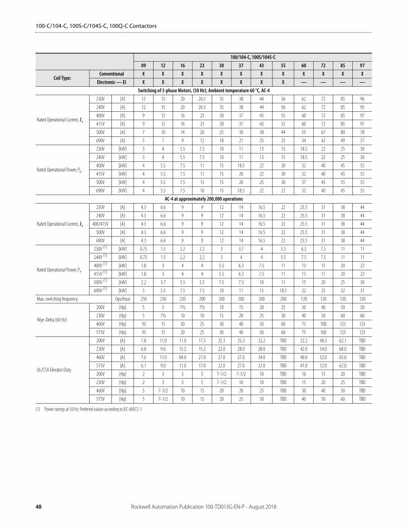
100-C/104-C, 100S-C/104S-C, 100Q-C Contactors
100/104-C, 100S/104S-C09 12 16 23 30 37 43 55 60 72 85 97
Coil Type:Conventional X X X X X X X X X X X X
Electronic — EI X X X X X X X X — — — —Switching of 3-phase Motors, (50 Hz); Ambient temperature 60 °C, AC-4
Rated Operational Current, Ie
230V [A] 12 15 20 26.5 35 38 44 56 62 72 85 96
240V [A] 12 15 20 26.5 35 38 44 56 62 72 85 95
400V [A] 9 12 16 23 30 37 43 55 60 72 85 97
415V [A] 9 12 16 23 30 37 43 55 60 72 85 97
500V [A] 7 10 14 20 25 30 38 44 55 67 80 78
690V [A] 5 7 9 12 18 21 25 25 34 42 49 57
Rated Operational Power, Pe
230V [kW] 3 4 5.5 7.5 10 11 13 15 18.5 22 25 30
240V [kW] 3 4 5.5 7.5 10 11 13 15 18.5 22 25 30
400V [kW] 4 5.5 7.5 11 15 18.5 22 30 32 40 45 55
415V [kW] 4 5.5 7.5 11 15 20 22 30 32 40 45 55
500V [kW] 4 5.5 7.5 13 15 20 25 30 37 45 55 55
690V [kW] 4 5.5 7.5 10 15 18.5 22 22 32 40 45 55
AC-4 at approximately 200,000 operations
Rated Operational Current, Ie
230V [A] 4.3 6.6 9 9 12 14 16.5 22 25.5 31 38 44
240V [A] 4.3 6.6 9 9 12 14 16.5 22 25.5 31 38 44
400/415V [A] 4.3 6.6 9 9 12 14 16.5 22 25.5 31 38 44
500V [A] 4.3 6.6 9 9 12 14 16.5 22 25.5 31 38 44
690V [A] 4.3 6.6 9 9 12 14 16.5 22 25.5 31 38 44
Rated Operational Power, Pe
230V (1)
(1) Power ratings at 50 Hz: Preferred values according to IEC 60072-1
[kW] 0.75 1.5 2.2 2.2 3 3.7 4 5.5 6.3 7.5 11 11
240V (1) [kW] 0.75 1.5 2.2 2.2 3 4 4 5.5 7.5 7.5 11 11
400V (1) [kW] 1.8 3 4 4 5.5 6.3 7.5 11 13 15 20 22
415V (1) [kW] 1.8 3 4 4 5.5 6.3 7.5 11 13 17 20 22
500V (1) [kW] 2.2 3.7 5.5 5.5 7.5 7.5 10 11 15 20 25 30
690V (1) [kW] 3 5.5 7.5 7.5 10 11 15 18.5 22 25 32 37
Max. switching frequency Ops/hour 250 250 220 200 200 200 200 200 120 120 120 120
Wye-Delta (60 Hz)
200V [Hp] 5 5 7½ 7½ 10 15 20 25 30 40 50 50
230V [Hp] 5 7½ 10 10 15 20 25 30 40 50 60 60
460V [Hp] 10 15 20 25 30 40 50 60 75 100 125 125
575V [Hp] 10 15 20 25 30 40 50 60 75 100 125 125
UL/CSA Elevator Duty
200V [A] 7.8 11.0 11.0 17.5 25.3 25.3 32.2 TBD 32.2 48.3 62.1 TBD
230V [A] 6.8 9.6 15.2 15.2 22.0 28.0 28.0 TBD 42.0 54.0 68.0 TBD
460V [A] 7.6 11.0 04.0 21.0 27.0 27.0 34.0 TBD 40.0 52.0 65.0 TBD
575V [A] 6.1 9.0 11.0 17.0 22.0 27.0 32.0 TBD 41.0 52.0 62.0 TBD
200V [Hp] 2 3 3 5 7-1/2 7-1/2 10 TBD 10 15 20 TBD
230V [Hp] 2 3 5 5 7-1/2 10 10 TBD 15 20 25 TBD
460V [Hp] 5 7-1/2 10 15 20 20 25 TBD 30 40 50 TBD
575V [Hp] 5 7-1/2 10 15 20 25 30 TBD 40 50 60 TBD
48 Rockwell Automation Publication 100-TD013G-EN-P - August 2018

100-C/104-C, 100S-C/104S-C, 100Q-C Contactors
100/104-C, 100S/104S-C09 12 16 23 30 37 43 55 60 72 85 97
Coil Type:Conventional X X X X X X X X X X X X
Electronic — EI X X X X X X X X — — — —Star-Delta Starting (50 Hz)
Rated Operational Current, Ie
≤ 230V [A] 21 26 35 46 61 66 76 96 107 125 147 166
≤ 240V [A] 21 26 35 46 61 66 76 96 107 125 47 165
400V [A] 16 21 28 40 52 64 74 95.3 104 125 147 168
415V [A] 16 21 28 40 52 64 74 95.3 104 125 47 168
500V [A] 12 17 24 35 43 52 66 76.2 95 116 139 135
690V [A] 8.6 12 16 21 31 36 43 55.4 59 73 85 99
Rated Operational Power, Pe
230V (1)
(1) Power ratings at 50 Hz: Preferred values according to IEC 60072-1
[kW] 5.5 7.5 10 13 17 20 22 30 32 37 45 50
240V (1) [kW] 5.5 7.5 10 13 18.5 20 22 30 32 40 50 50
400V (1) [kW] 7.5 10 13 20 25 32 40 45 55 63 80 90
415V (1) [kW] 7.5 11 15 22 25 32 40 45 55 63 80 90
500V (1) [kW] 7.5 11 15 22 25 32 45 45 63 80 90 90
690V (1) [kW] 7.5 10 13 18.5 25 32 40 45 55 63 80 90
Switching of Power Transformers, AC-6a (50 Hz))
n= 30
≤ 230V [A] 10.9 10.9 10.9 10.9 20 20 23 23 40.8 40.8 40.8 48.5
≤ 240V [A] 10.9 10.9 10.9 10.9 20 20 23 23 40.8 40.8 40.8 48.5
≤ 400V [A] 10.9 10.9 10.9 10.9 20 20 23 23 40.8 40.8 40.8 48.5
≤ 415V [A] 10.9 10.9 10.9 10.9 20 20 23 23 40.8 40.8 40.8 48.5
≤ 500V [A] 10.9 10.9 10.9 10.9 20 20 23 23 40.8 40.8 40.8 48.5
≤ 690V [A] 10.9 10.9 10.9 10.9 20 20 23 23 40.8 40.8 40.8 48.5
Apparent Power
230V [kVA] 4.3 4.3 4.3 4.3 8 8 9.2 9.2 16 16 16 19.3
240V [kVA] 4.5 4.5 4.5 4.5 8.3 8.3 10 10 17 17 17 20.2
400V [kVA] 7.5 7.5 7.5 7.5 14 14 16 16 28 28 28 33.6
415V [kVA] 7.8 7.8 7.8 7.8 14 14 17 17 29 29 29 34.9
500V [kVA] 9.4 9.4 9.4 9.4 17 17 20 20 35 35 35 42
690V [kVA] 13 13 13 13 24 24 27 27 49 49 49 58
n=20 ≤ 690V [A] 16.3 16.3 16.3 16.3 30 30 34.5 34.5 61.3 61.3 61.3 72.8
n=15 ≤ 690V [A] 22 22 22 22 40 40 46 46 82 82 82 97
60 Hz Peak Inrush/peak rated transformer currentn=30 [A] 10.9 10.9 10.9 10.9 20 20 23 23 40.8 40.8 40.8 48.5
Apparent Power
200V [kVA] 3.8 3.8 3.8 3.8 6.9 6.9 8.0 8 14.1 14.4 14.4 16.8
208V [kVA] 3.9 3.9 3.9 3.9 7.2 7.2 8.3 8.3 14.7 14.7 14.7 17.5
240V [kVA] 4.5 4.5 4.5 4.5 8.3 8.3 9.6 9.6 17.0 17.0 17.0 20.2
480V [kVA] 9.1 9.1 9.1 9.1 16.6 16.6 19.1 19.1 33.9 33.9 33.9 40.3
600V [kVA] 11.3 11.3 11.3 11.3 20.8 20.8 23.9 23.9 42.4 42.4 42.4 50.4
660V [kVA] 12.5 12.5 12.5 12.5 22.9 22.9 26.3 26.3 46.6 46.6 46.6 55.4
60 Hz Peak Inrush/peak rated transformer currentn=20 [A] 16.3 16.3 16.3 16.3 30 30 34.5 34.5 61.3 61.3 61.3 72.8
Apparent Power
200V [kVA] 5.6 5.6 5.6 5.6 10.4 10.4 12.0 12 21.2 21.2 21.2 25.2
208V [kVA] 5.9 5.9 5.9 5.9 10.8 10.8 12.4 12.4 22.1 22.1 22.1 26.2
240V [kVA] 6.8 6.8 6.8 6.8 12.5 12.5 14.3 14.3 25.5 25.5 25.5 30.3
480V [kVA] 13.6 13.6 13.6 13.6 24.9 24.9 28.7 28.7 51.0 51.0 51.0 60.5
600V [kVA] 16.9 16.9 16.9 16.9 31.2 31.2 35.9 35.9 63.7 63.7 63.7 75.7
660V [kVA] 18.6 18.6 18.6 18.6 34.3 34.3 39.4 39.4 70.1 70.1 70.1 83.2
Inrush CurrentRated transformer current
= n
Rockwell Automation Publication 100-TD013G-EN-P - August 2018 49
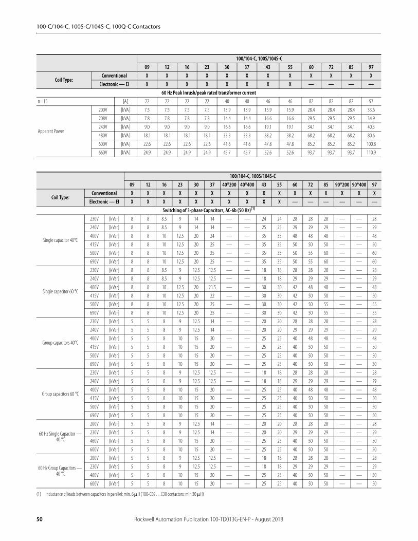
100-C/104-C, 100S-C/104S-C, 100Q-C Contactors
100/104-C, 100S/104S-C09 12 16 23 30 37 43 55 60 72 85 97
Coil Type:Conventional X X X X X X X X X X X X
Electronic — EI X X X X X X X X — — — —60 Hz Peak Inrush/peak rated transformer current
n=15 [A] 22 22 22 22 40 40 46 46 82 82 82 97
Apparent Power
200V [kVA] 7.5 7.5 7.5 7.5 13.9 13.9 15.9 15.9 28.4 28.4 28.4 33.6
208V [kVA] 7.8 7.8 7.8 7.8 14.4 14.4 16.6 16.6 29.5 29.5 29.5 34.9
240V [kVA] 9.0 9.0 9.0 9.0 16.6 16.6 19.1 19.1 34.1 34.1 34.1 40.3
480V [kVA] 18.1 18.1 18.1 18.1 33.3 33.3 38.2 38.2 68.2 68.2 68.2 80.6
600V [kVA] 22.6 22.6 22.6 22.6 41.6 41.6 47.8 47.8 85.2 85.2 85.2 100.8
660V [kVA] 24.9 24.9 24.9 24.9 45.7 45.7 52.6 52.6 93.7 93.7 93.7 110.9
100/104-C, 100S/104S-C09 12 16 23 30 37 40*200 40*400 43 55 60 72 85 90*200 90*400 97
Coil Type:Conventional X X X X X X X X X X X X X X X X
Electronic — EI X X X X X X X X X X — — — — — —Switching of 3-phase Capacitors, AC-6b (50 Hz)(1)
(1) Inductance of leads between capacitors in parallel: min. 6 H (100-C09…C30 contactors: min 30 H)
Single capacitor 40°C
230V [kVar] 8 8 8.5 9 14 14 — — 24 24 28 28 28 — — 28
240V [kVar] 8 8 8.5 9 14 14 — — 25 25 29 29 29 — — 29
400V [kVar] 8 8 10 12.5 20 24 — — 35 35 48 48 48 — — 48
415V [kVar] 8 8 10 12.5 20 25 — — 35 35 50 50 50 — — 50
500V [kVar] 8 8 10 12.5 20 25 — — 35 35 50 55 60 — — 60
690V [kVar] 8 8 10 12.5 20 25 — — 35 35 50 55 60 — — 60
Single capacitor 60 °C
230V [kVar] 8 8 8.5 9 12.5 12.5 — — 18 18 28 28 28 — — 28
240V [kVar] 8 8 8.5 9 12.5 12.5 — — 18 18 29 29 29 — — 29
400V [kVar] 8 8 10 12.5 20 21.5 — — 30 30 42 48 48 — — 48
415V [kVar] 8 8 10 12.5 20 22 — — 30 30 42 50 50 — — 50
500V [kVar] 8 8 10 12.5 20 25 — — 30 30 42 50 55 — — 55
690V [kVar] 8 8 10 12.5 20 25 — — 30 30 42 50 55 — — 55
Group capacitors 40°C
230V [kVar] 5 5 8 9 12.5 14 — — 20 20 28 28 28 — — 28
240V [kVar] 5 5 8 9 12.5 14 — — 20 20 29 29 29 — — 29
400V [kVar] 5 5 8 10 15 20 — — 25 25 40 48 48 — — 48
415V [kVar] 5 5 8 10 15 20 — — 25 25 40 50 50 — — 50
500V [kVar] 5 5 8 10 15 20 — — 25 25 40 50 50 — — 50
690V [kVar] 5 5 8 10 15 20 — — 25 25 40 50 50 — — 50
Group capacitors 60 °C
230V [kVar] 5 5 8 9 12.5 12.5 — — 18 18 28 28 28 — — 28
240V [kVar] 5 5 8 9 12.5 12.5 — — 18 18 29 29 29 — — 29
400V [kVar] 5 5 8 10 15 20 — — 25 25 40 48 48 — — 48
415V [kVar] 5 5 8 10 15 20 — — 25 25 40 50 50 — — 50
500V [kVar] 5 5 8 10 15 20 — — 25 25 40 50 50 — — 50
690V [kVar] 5 5 8 10 15 20 — — 25 25 40 50 50 — — 50
60 Hz Single Capacitor — 40 °C
200V [kVar] 5 5 8 9 12.5 14 — — 20 20 28 28 28 — — 28
230V [kVar] 5 5 8 9 12.5 14 — — 20 20 29 29 29 — — 29
460V [kVar] 5 5 8 10 15 20 — — 25 25 40 50 50 — — 50
600V [kVar] 5 5 8 10 15 20 — — 25 25 40 50 50 — — 50
60 Hz Group Capacitors — 40 °C
200V [kVar] 5 5 8 9 12.5 12.5 — — 18 18 28 28 28 — — 28
230V [kVar] 5 5 8 9 12.5 12.5 — — 18 18 29 29 29 — — 29
460V [kVar] 5 5 8 10 15 20 — — 25 25 40 50 50 — — 50
600V [kVar] 5 5 8 10 15 20 — — 25 25 40 50 50 — — 50
50 Rockwell Automation Publication 100-TD013G-EN-P - August 2018
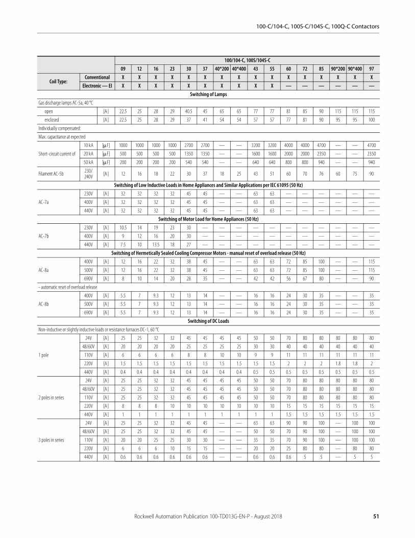
100-C/104-C, 100S-C/104S-C, 100Q-C Contactors
100/104-C, 100S/104S-C09 12 16 23 30 37 40*200 40*400 43 55 60 72 85 90*200 90*400 97
Coil Type:Conventional X X X X X X X X X X X X X X X X
Electronic — EI X X X X X X X X X X — — — — — —Switching of Lamps
Gas discharge lamps AC-5a, 40 °C
open [A] 22.5 25 28 29 40.5 45 65 65 77 77 81 85 90 115 115 115
enclosed [A] 22.5 25 28 29 37 41 54 54 57 57 77 81 90 95 95 100
Individually compensated:
Max. capacitance at expected
Short-circuit current of
10 kA [F] 1000 1000 1000 1000 2700 2700 — — 3200 3200 4000 4000 4700 — — 4700
20 kA [F] 500 500 500 500 1350 1350 — — 1600 1600 2000 2000 2350 — — 2350
50 kA [F] 200 200 200 200 540 540 — — 640 640 800 800 940 — — 940
Filament AC-5b 230/240V [A] 12 16 18 22 30 37 18 25 43 51 60 70 76 60 75 90
Switching of Low Inductive Loads in Home Appliances and Similar Applications per IEC 61095 (50 Hz)
AC-7a
230V [A] 32 32 32 32 45 45 — — 63 63 — — — — — —
400V [A] 32 32 32 32 45 45 — — 63 63 — — — — — —
440V [A] 32 32 32 32 45 45 — — 63 63 — — — — — —
Switching of Motor Load for Home Appliances (50 Hz)
AC-7b
230V [A] 10.5 14 19 23 30 — — — — — — — — — — —
400V [A] 9 12 16 20 30 — — — — — — — — — — —
440V [A] 7.5 10 13.5 18 27 — — — — — — — — — — —
Switching of Hermetically Sealed Cooling Compressor Motors - manual reset of overload release (50 Hz)
AC-8a
400V [A] 12 16 22 32 38 45 — — 63 63 72 85 100 — — 115
500V [A] 12 16 22 32 38 45 — — 63 63 72 85 100 — — 115
690V [A] 8 10 14 20 28 35 — — 42 42 56 67 80 — — 90
- automatic reset of overload release
AC-8b
400V [A] 5.5 7 9.3 12 13 14 — — 16 16 24 30 35 — — 35
500V [A] 5.5 7 9.3 12 13 14 — — 16 16 24 30 35 — — 35
690V [A] 5.5 7 9.3 12 13 14 — — 16 16 24 30 35 — — 35
Switching of DC LoadsNon-inductive or slightly inductive loads or resistance furnaces DC-1, 60 °C
1 pole
24V [A] 25 25 32 32 45 45 45 45 50 50 70 80 80 80 80 80
48/60V [A] 20 20 20 20 25 25 25 25 30 30 40 40 40 40 40 40
110V [A] 6 6 6 6 8 8 10 10 9 9 11 11 11 11 11 11
220V [A] 1.5 1.5 1.5 1.5 1.5 1.5 1.5 1.5 1.5 1.5 2 2 2 1.8 1.8 2
440V [A] 0.4 0.4 0.4 0.4 0.4 0.4 0.4 0.4 0.5 0.5 0.5 0.5 0.5 0.5 0.5 0.5
2 poles in series
24V [A] 25 25 32 32 45 45 45 45 50 50 70 80 80 80 80 80
48/60V [A] 25 25 32 32 45 45 45 45 50 50 70 80 80 80 80 80
110V [A] 25 25 32 32 45 45 45 45 50 50 70 80 80 80 80 80
220V [A] 8 8 8 10 10 10 10 10 10 10 15 15 15 15 15 15
440V [A] 1 1 1 1 1 1 1 1 1 1 1.5 1.5 1.5 1.5 1.5 1.5
3 poles in series
24V [A] 25 25 32 32 45 45 — — 63 63 90 90 100 — 100 100
48/60V [A] 25 25 32 32 45 45 — — 50 50 70 90 100 — 100 100
110V [A] 20 20 25 25 30 30 — — 35 35 70 90 100 — 100 100
220V [A] 6 6 6 10 15 15 — — 20 20 25 80 80 — 80 80
440V [A] 0.6 0.6 0.6 0.6 0.6 0.6 — — 0.6 0.6 0.6 5 5 — 5 5
Rockwell Automation Publication 100-TD013G-EN-P - August 2018 51
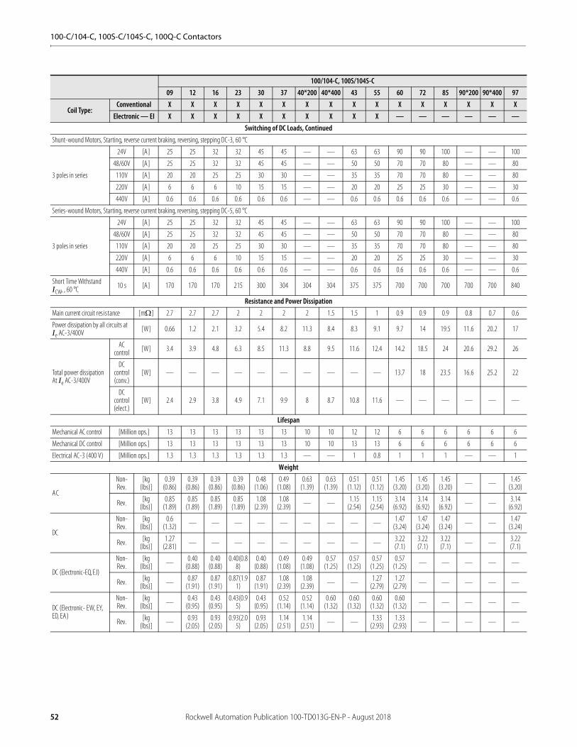
100-C/104-C, 100S-C/104S-C, 100Q-C Contactors
100/104-C, 100S/104S-C09 12 16 23 30 37 40*200 40*400 43 55 60 72 85 90*200 90*400 97
Coil Type:Conventional X X X X X X X X X X X X X X X X
Electronic — EI X X X X X X X X X X — — — — — —Switching of DC Loads, Continued
Shunt-wound Motors, Starting, reverse current braking, reversing, stepping DC-3, 60 °C
3 poles in series
24V [A] 25 25 32 32 45 45 — — 63 63 90 90 100 — — 100
48/60V [A] 25 25 32 32 45 45 — — 50 50 70 70 80 — — 80
110V [A] 20 20 25 25 30 30 — — 35 35 70 70 80 — — 80
220V [A] 6 6 6 10 15 15 — — 20 20 25 25 30 — — 30
440V [A] 0.6 0.6 0.6 0.6 0.6 0.6 — — 0.6 0.6 0.6 0.6 0.6 — — 0.6
Series-wound Motors, Starting, reverse current braking, reversing, stepping DC-5, 60 °C
3 poles in series
24V [A] 25 25 32 32 45 45 — — 63 63 90 90 100 — — 100
48/60V [A] 25 25 32 32 45 45 — — 50 50 70 70 80 — — 80
110V [A] 20 20 25 25 30 30 — — 35 35 70 70 80 — — 80
220V [A] 6 6 6 10 15 15 — — 20 20 25 25 30 — — 30
440V [A] 0.6 0.6 0.6 0.6 0.6 0.6 — — 0.6 0.6 0.6 0.6 0.6 — — 0.6
Short Time Withstand ICW, , 60 °C 10 s [A] 170 170 170 215 300 304 304 304 375 375 700 700 700 700 700 840
Resistance and Power DissipationMain current circuit resistance [m] 2.7 2.7 2.7 2 2 2 2 1.5 1.5 1 0.9 0.9 0.9 0.8 0.7 0.6
Power dissipation by all circuits at Ie AC-3/400V [W] 0.66 1.2 2.1 3.2 5.4 8.2 11.3 8.4 8.3 9.1 9.7 14 19.5 11.6 20.2 17
Total power dissipation At Ie AC-3/400V
AC control [W] 3.4 3.9 4.8 6.3 8.5 11.3 8.8 9.5 11.6 12.4 14.2 18.5 24 20.6 29.2 26
DC control (conv.)
[W] — — — — — — — — — — 13.7 18 23.5 16.6 25.2 22
DC control (elect.)
[W] 2.4 2.9 3.8 4.9 7.1 9.9 8 8.7 10.8 11.6 — — — — — —
LifespanMechanical AC control [Million ops.] 13 13 13 13 13 13 10 10 12 12 6 6 6 6 6 6
Mechanical DC control [Million ops.] 13 13 13 13 13 13 10 10 13 13 6 6 6 6 6 6
Electrical AC-3 (400 V) [Million ops.] 1.3 1.3 1.3 1.3 1.3 1.3 — — 1 0.8 1 1 1 — — 1
Weight
AC
Non-Rev.
[kg (lbs)]
0.39 (0.86)
0.39 (0.86)
0.39 (0.86)
0.39 (0.86)
0.48 (1.06)
0.49 (1.08)
0.63 (1.39)
0.63 (1.39)
0.51 (1.12)
0.51 (1.12)
1.45 (3.20)
1.45 (3.20)
1.45 (3.20) — — 1.45
(3.20)
Rev. [kg (lbs)]
0.85 (1.89)
0.85 (1.89)
0.85 (1.89)
0.85 (1.89)
1.08 (2.39)
1.08 (2.39) — — 1.15
(2.54)1.15
(2.54)3.14
(6.92)3.14
(6.92)3.14
(6.92) — — 3.14 (6.92)
DC
Non-Rev.
[kg (lbs)]
0.6 (1.32) — — — — — — — — — 1.47
(3.24)1.47
(3.24)1.47
(3.24) — — 1.47 (3.24)
Rev. [kg (lbs)]
1.27 (2.81) — — — — — — — — — 3.22
(7.1)3.22 (7.1)
3.22 (7.1) — — 3.22
(7.1)
DC (Electronic-EQ, EJ)
Non-Rev.
[kg (lbs)] — 0.40
(0.88)0.40
(0.88)0.40(0.8
8)0.40
(0.88)0.49
(1.08)0.49
(1.08)0.57
(1.25)0.57
(1.25)0.57
(1.25)0.57
(1.25) — — — — —
Rev. [kg (lbs)] — 0.87
(1.91)0.87
(1.91)0.87(1.9
1)0.87
(1.91)1.08
(2.39)1.08
(2.39) — — 1.27 (2.79)
1.27 (2.79) — — — — —
DC (Electronic- EW, EY, ED, EA)
Non-Rev.
[kg (lbs)] — 0.43
(0.95)0.43
(0.95)0.43(0.9
5)0.43
(0.95)0.52
(1.14)0.52
(1.14)0.60
(1.32)0.60
(1.32)0.60
(1.32)0.60
(1.32) — — — — —
Rev. [kg (lbs)] — 0.93
(2.05)0.93
(2.05)0.93(2.0
5)0.93
(2.05)1.14
(2.51)1.14
(2.51) — — 1.33 (2.93)
1.33 (2.93) — — — — —
52 Rockwell Automation Publication 100-TD013G-EN-P - August 2018

100-C/104-C, 100S-C/104S-C, 100Q-C Contactors
100/104-C, 100S/104S-C09 12 16 23 30 37 40 43 55 60 72 85 90 97
Coil Type:Conventional X X X X X X X X X X X X X X
Electronic — EI X X X X X X X X X — — — — —
Conductor Cross Sections - Main Contacts Terminal type(1)
(1) Pozidriv No. 2 / Blade No. 3 screw
(2)
(2) Pozidriv No. 2 / Blade No. 4 screw
(3)
(3) Hexagonal socket screw
1 conductor [mm2] 1…4 2.5…10 2.5…16 2.5…35
2 conductors [mm2] 1…4 2.5…10 2.5…10 2.5…25
1 conductor [mm2] 1.5…6 2.5…16 2.5…25 2.5…50
2 conductors [mm2] 1.5…6 2.5…16 2.5…16 2.5…35
Recommended torque [N•m] 1.5…2.0 2.5…3.5 2.5…3.5 4.5…6
Cros s s ection per UL/CSA [AWG] 16…10 14…4 14…6 14…4 14…1
Recommended torque [lb-in] 13.3…17.7 22…31 22…31 40…53
Conductor Cross Sections - Coil Terminal type(1)
1 conductor [mm2] 1…2.5
2 conductors [mm2] 1…2.5
1 conductor [mm2] 1…4
2 conductors [mm2] 1…4
Recommended torque [N•m] 1…1.5
Cros s s ection per UL/CSA [AWG] 16…12
Recommended torque [lb-in] 9…13
Rockwell Automation Publication 100-TD013G-EN-P - August 2018 53

100-C/104-C, 100S-C/104S-C, 100Q-C Contactors
Short-Circuit Coordination Data
See http://www.rockwellautomation.com/global/support/global-sccr.page? for complete short-circuit current ratings.
100/104-C, 100S/104S-C09 12 16 23 30 37 40*200 40*400 43 55 60 72 85 90*200 90*400 97
Coil Type:Conventional X X X X X X X X X X X X X X X XElectronic - EI X X X X X X X X X X — — — — — —
Short Circuit Coordination (Max. Fuse or Circuit Breaker Rating) Per IEC 60947-4-1 (contactor and fuses only)
DIN Fuses- gG, gL
50 kA Available Fault Current
Type"1"(690V) [A] 50 50 50 80 125 125 160 160 160 160 250 250 250 250 250 250
Type"2"(400V) [A] 25 35 35 40 80 80 63 80 100 100 160 160 160 160 100 200
Type"2"(690V) [A] 25 35 35 40 80 80 63 80 100 100 160 160 160 160 100 200
BS88Fuses
65kA Available Fault Current
Type"1"(415V) [A] 25 32 40 50 63 80 — — 80 TBD 100 160 160 — — TBD
Type"2"(415V) [A] 20 25 32 50 63 80 — — 80 TBD 100 125 160 — — TBD
Per UL 508 and CSA 22.2 No. 14 (contactor and fuses or circuit breaker only)
UL Class K5 and RK5 Fuses
UL Listed Combination (600V)
5 kA Available Fault Current
[A] 35 40 70 90 110 125 125 125 150 200 200 — — — — —
10 kA Available Fault Current
[A] — — — — — — — — — — — 250 300 300 300 350
UL Class CC and CSA HRCI-MISC Fuses
UL verified combination to IEC60947-4-1 "Type2"
100 kA Available Fault Current
[A] 20(1)
(1) 15 A max. fuse for Type 2 coordination.
20 30 40 — — — — — — — — — — — —
UL Class J and CSA HRCI-J Fuses
UL verified combination to IEC60947-4-1 "Type2"
100 kA Available Fault Current
[A] 20(1) 20 30 40 50 50 — — 70 TBD 80 100 150 — — 175
5 kA Available Fault Current
UL Inverse-Time Circuit Breaker
UL Listed Combination (480V) [A] 30 30 50 50 125 125 — — 125 150 250 — — — — —
UL Listed Combination (600V)
[A] — — — — 125 125 — — 125 150 250 — — — — —
10 kA Available Fault Current
[A] — — — — — — — — — — — 250 250 — — 250
18 kA Available Fault Current
[A] — — — — — — — — — — — — — — — —
UL Lis ted Combination (600Y/347V)
25 kA Available Fault Current
[A] 30(2)
(2) Ratings apply when used with Bulletin 140U-D circuit breakers only.
30(2) 30(2) 30(2) 50(3)
(3) Minimum enclosure size 12-3/8 x 7-5/8 s 7-1/4 inches
50(3) — — 50(3) — 110 110 110 — — —
UL Listed Combination (600V) [A] — — — — 100(4)
(4) Minimum enclosure size 20 x 12 x 8 inches with two latches.
100(4) — — 100(4) 125 200(4) 225(4) 225(4) — — 225(4)
UL Listed Combination (480V)
50 kA Available Fault Current
[A] — — — — 50(3) 50(3) — — 50(3) — — — — — — —
UL Listed Combination (480Y/277V)
65 kA Available Fault Current
[A] 30(2) 30(2) 30(2) 30(2) — — — — — — — — — — — —
UL Listed Combination (480V) [A] — — — — 100(4) 100(4) — — 100(4) 125 200(4) 225(4) 225(4) — — 225(4)
54 Rockwell Automation Publication 100-TD013G-EN-P - August 2018
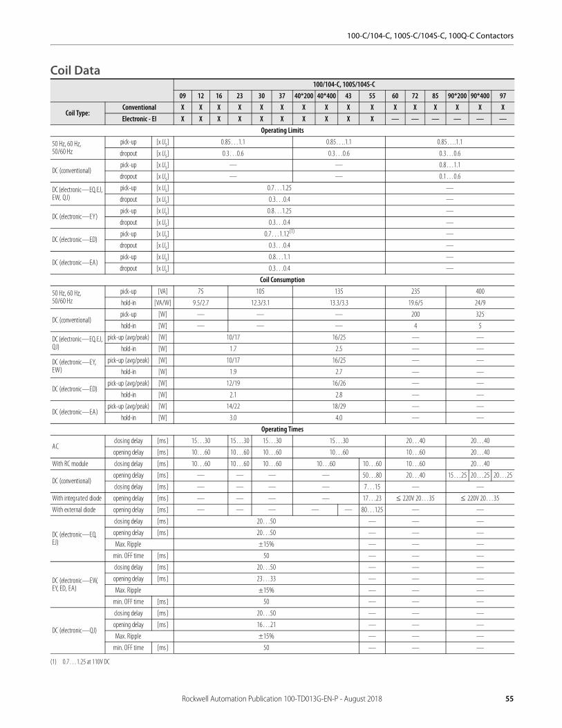
100-C/104-C, 100S-C/104S-C, 100Q-C Contactors
Coil Data100/104-C, 100S/104S-C
09 12 16 23 30 37 40*200 40*400 43 55 60 72 85 90*200 90*400 97
Coil Type:Conventional X X X X X X X X X X X X X X X XElectronic - EI X X X X X X X X X X — — — — — —
Operating Limits
50 Hz, 60 Hz, 50/60 Hz
pick-up [x Us] 0.85…1.1 0.85….1.1 0.85….1.1
dropout [x Us] 0.3…0.6 0.3…0.6 0.3…0.6
DC (conventional)pick-up [x Us] — — 0.8…1.1
dropout [x Us] — — 0.1…0.6
DC (electronic—EQ, EJ, EW, QJ)
pick-up [x Us] 0.7…1.25 —
dropout [x Us] 0.3…0.4 —
DC (electronic—EY)pick-up [x Us] 0.8…1.25 —
dropout [x Us] 0.3…0.4 —
DC (electronic—ED)pick-up [x Us] 0.7…1.12(1)
(1) 0.7…1.25 at 110V DC
—
dropout [x Us] 0.3…0.4 —
DC (electronic—EA)pick-up [x Us] 0.8…1.1 —
dropout [x Us] 0.3…0.4 —
Coil Consumption
50 Hz, 60 Hz, 50/60 Hz
pick-up [VA] 75 105 135 235 400
hold-in [VA/W] 9.5/2.7 12.3/3.1 13.3/3.3 19.6/5 24/9
DC (conventional)pick-up [W] — — — 200 325
hold-in [W] — — — 4 5
DC (electronic—EQ, EJ, QJ)
pick-up (avg/peak) [W] 10/17 16/25 — —
hold-in [W] 1.7 2.5 — —
DC (electronic—EY, EW)
pick-up (avg/peak) [W] 10/17 16/25 — —
hold-in [W] 1.9 2.7 — —
DC (electronic—ED)pick-up (avg/peak) [W] 12/19 16/26 — —
hold-in [W] 2.1 2.8 — —
DC (electronic—EA)pick-up (avg/peak) [W] 14/22 18/29 — —
hold-in [W] 3.0 4.0 — —
Operating Times
ACclos ing delay [ms] 15…30 15…30 15…30 15…30 20…40 20…40
opening delay [ms] 10…60 10…60 10…60 10…60 10…60 20…40
With RC module clos ing delay [ms] 10…60 10…60 10…60 10…60 10…60 10…60 20…40
DC (conventional)opening delay [ms] — — — — 50…80 20…40 15…25 20…25 20…25
clos ing delay [ms] — — — — 7…15 — —
With integrated diode opening delay [ms] — — — — 17…23 220V 20…35 220V 20…35
With external diode opening delay [ms] — — — — — 80…125 — —
DC (electronic—EQ, EJ)
clos ing delay [ms] 20…50 — — —
opening delay [ms] 20…50 — — —
Max. Ripple ±15% — — —
min. OFF time [ms] 50 — — —
DC (electronic—EW, EY, ED, EA)
clos ing delay [ms] 20…50 — — —
opening delay [ms] 23…33 — — —
Max. Ripple ±15% — — —
min. OFF time [ms] 50 — — —
DC (electronic—QJ)
clos ing delay [ms] 20…50 — — —
opening delay [ms] 16…21 — — —
Max. Ripple ±15% — — —
min. OFF time [ms] 50 — — —
Rockwell Automation Publication 100-TD013G-EN-P - August 2018 55

100-C/104-C, 100S-C/104S-C, 100Q-C Contactors
Auxiliary Contacts, Auxiliary Contact Blocks, and Pneumatic Timers
Internal Front mounted Front mounted (Bifurcated) Side-mounted
Switching of AC Loads
AC-12 Ithat 40 °C [A] 20 10 10 10
at 60 °C [A] 20 6 6 6
AC-15 at rated voltage of
24V [A] 10 6 3 6
42/48V [A] 10 6 3 6
120V [A] 10 6 3 6
230V [A] 10 5.5 3 5.5
240V [A] 10 5 3 5
400V [A] 6 3 2 3
415V [A] 6 3 2 3
500V [A] 2.5 1.6 1.2 1.6
690V [A] 1 1 0.7 1
Switching of DC Loads
DC-12 L/R < 1 ms res is tive loads at
24V DC [A] 12 12 6 6
48V DC [A] 9 9 3.2 3.2
110V DC [A] 3.5 3.5 1 1
220V DC [A] 0.55 0.55 0.5 0.5
440V DC [A] 0.2 0.2 0.2 0.2
DC-14L/R <15 ms inductive loads with economy resistor in series at
24V DC [A] 9 9 2 2
48V DC [A] 5 5 1.6 1.6
110V DC [A] 2 2 0.3 0.3
220V DC [A] 0.4 0.4 0.12 0.12
440V DC [A] 0.16 0.16 0.05 0.05
DC-13 switching electromagnets at
24V DC [A] 5 5 2.5 5
48V DC [A] 3 3 1.5 2.5
110V DC [A] 1.2 1.2 0.6 0.68
220V DC [A] 0.6 0.6 0.3 0.32
440V DC [A] 0.3 0.15 0.15 0.15
Fuse gG
Short-circuit protection with no welding of contacts per IEC 60947-5-1
[A] 20 10 10 10
[A] 20 10 10 10
Protective Separation per IEC 60947-1, Annex N between load and auxiliary circuit 320V between load and auxiliary circuit 440V
Min. switching capacity according to IEC 60947-5-4 17V/10mA 17V/5mA 5V/3mA 17V/10mA
Load Carrying Capacity per UL/CSARated voltage AC [V] max.600
Continuous rating 40 °C [A] 10 10 10 10
Switching capacity AC [A] A600
Rated voltage DC [V] max.600
Switching capacity DC [A] P600 Q600 Q600
56 Rockwell Automation Publication 100-TD013G-EN-P - August 2018
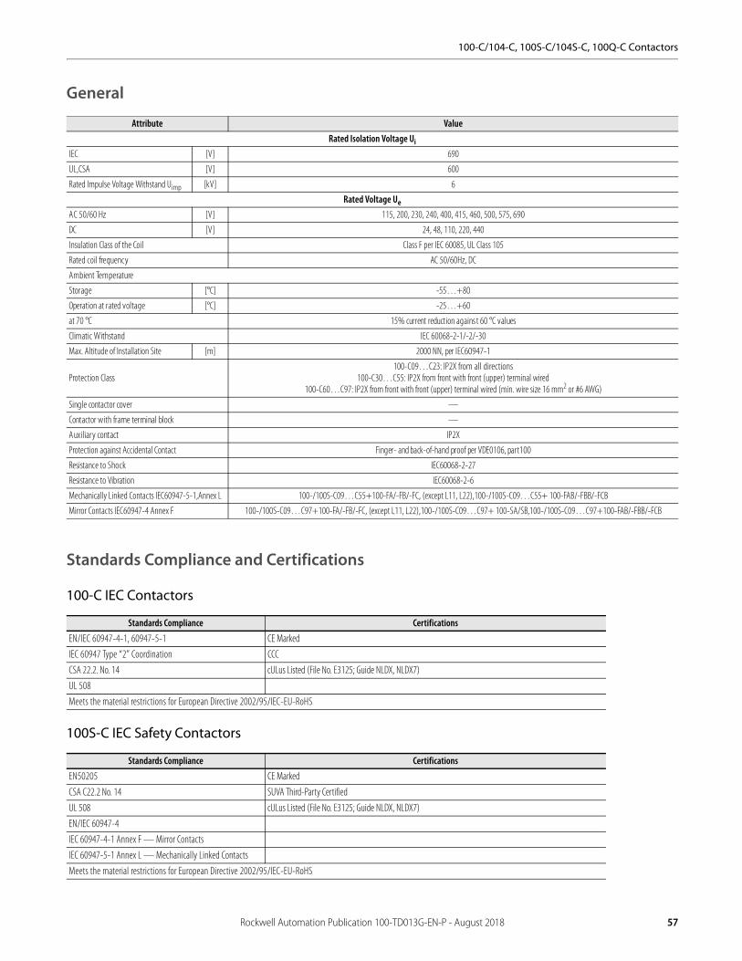
100-C/104-C, 100S-C/104S-C, 100Q-C Contactors
General
Standards Compliance and Certifications
100-C IEC Contactors
100S-C IEC Safety Contactors
Attribute ValueRated Isolation Voltage Ui
IEC [V] 690
UL,CSA [V] 600
Rated Impulse Voltage Withstand Uimp [kV] 6
Rated Voltage Ue
AC 50/60 Hz [V] 115, 200, 230, 240, 400, 415, 460, 500, 575, 690
DC [V] 24, 48, 110, 220, 440
Insulation Class of the Coil Class F per IEC 60085, UL Class 105
Rated coil frequency AC 50/60Hz, DC
Ambient Temperature
Storage [°C] -55…+80
Operation at rated voltage [°C] -25…+60
at 70 °C 15% current reduction agains t 60 °C values
Climatic Withstand IEC 60068-2-1/-2/-30
Max. Altitude of Installation Site [m] 2000 NN, per IEC60947-1
Protection Class100-C09…C23: IP2X from all directions
100-C30…C55: IP2X from front with front (upper) terminal wired100-C60…C97: IP2X from front with front (upper) terminal wired (min. wire size 16 mm2 or #6 AWG)
Single contactor cover —
Contactor with frame terminal block —
Auxiliary contact IP2X
Protection against Accidental Contact Finger- and back-of-hand proof per VDE0106, part100
Resistance to Shock IEC60068-2-27
Resistance to Vibration IEC60068-2-6
Mechanically Linked Contacts IEC60947-5-1,Annex L 100-/100S-C09…C55+100-FA/-FB/-FC, (except L11, L22),100-/100S-C09…C55+ 100-FAB/-FBB/-FCB
Mirror Contacts IEC60947-4 Annex F 100-/100S-C09…C97+100-FA/-FB/-FC, (except L11, L22),100-/100S-C09…C97+ 100-SA/SB,100-/100S-C09…C97+100-FAB/-FBB/-FCB
Standards Compliance Certifications
EN/IEC 60947-4-1, 60947-5-1 CE Marked
IEC 60947 Type “2” Coordination CCC
CSA 22.2. No. 14 cULus Listed (File No. E3125; Guide NLDX, NLDX7)
UL 508
Meets the material restrictions for European Directive 2002/95/IEC-EU-RoHS
Standards Compliance Certifications
EN50205 CE Marked
CSA C22.2 No. 14 SUVA Third-Party Certified
UL 508 cULus Listed (File No. E3125; Guide NLDX, NLDX7)
EN/IEC 60947-4
IEC 60947-4-1 Annex F — Mirror Contacts
IEC 60947-5-1 Annex L — Mechanically Linked Contacts
Meets the material restrictions for European Directive 2002/95/IEC-EU-RoHS
Rockwell Automation Publication 100-TD013G-EN-P - August 2018 57
100-C/104-C, 100S-C/104S-C, 100Q-C Contactors
100Q-C Capacitor-switching Contactors
Life-Load CurvesBulletin 100-C/104-C IEC contactors are designed for superior performance in a wide variety of applications. When selecting IEC products, the user must give consideration to the specific load, utilization category, and required electrical life of the application. The life-load curves shown here are based on Rockwell Automation tests according to the requirements defined in IEC 60947-4-1. Since contact life in application is dependent on environmental conditions and duty cycle, actual application contact life may vary from that indicated by the curves shown here.
To find the contactor’s estimated electrical life, follow these guidelines:
1. Identify the appropriate utilization category from Table 1.
2. Choose the graph for the utilization category selected.
3. Locate the intersection of the life-load curve for the appropriate contactor with the application’s operational current (Ie) found on the horizontal axis.
4. Read the estimated contact life along the vertical axis.
Contact Life for Mixed Utilization Categories AC-3 and AC-4:
In many applications, the utilization category cannot be defined as either purely AC-3 or AC-4. In those applications, the electrical life of the contactor can be estimated from the following equation:
Lmixed = Lac3/[1 + Pac4*(Lac3/Lac4 – 1)], where:
Lmixed = Approximate contact life in operations for a mixed AC-3/AC-4 utilization category application
Lac3 = Approximate contact life in operations for a pure AC-3 utilization category (from the AC-3 life-load curves)
Lac4 = Approximate contact life in operations for a pure AC-4 utilization category (from the AC-4 life-load curves)
Pac4 = Percentage of AC-4 operations
Standards Compliance Certifications
IEC 60947-4 CE Marked
CSA C22.2 No. 14 cULus Listed (File No. E 41850, Guide NLDX, NLDX7)
UL 508
Meets the material restrictions for European Directive 2002/95/IEC-EU-RoHS
58 Rockwell Automation Publication 100-TD013G-EN-P - August 2018

100-C/104-C, 100S-C/104S-C, 100Q-C Contactors
Table 1 - Utilization Category Determination
Ie Rated operational current
I Making CurrentIc Breaking Current
U Off-load voltageUe Rated voltage
Ur Recovery voltage
Figure 5 - AC-1, 40 °C Non- or slightly inductive loads, resistance furnaces; Ue = 230…690V
Test ConditionsMaking Breaking
I/Ie U/Ue cos Ic/Ie Ur/Ue cos
AC-1Resistance Furnaces:Non inductive or slightly inductive loads
1 1 0.95 1 1 0.95
AC-2Slip-ring motors:Starting and reversing
2.5 1 0.65 2.5 1 0.65
AC-3Squirrel-cage motors:Starting and stopping of running motors
Ie < 17 AIe > 17 A
66
11
0.650.35
11
0.170.17
0.650.35
AC-4Squirrel-cage motors:Starting, plugging(1) , inching(2)
(1) Plugging is understood as stopping or reversing the motor rapidly by reversing motor primary connections while the motor is running.(2) Inching (jogging) is understood as energizing a motor once or repeatedly for short periods to obtain small movements of the driven mechanism.
Ie < 17 AIe > 17 A
66
11
0.650.35
66
11
0.650.35
AC-15Solenoids:Contactors, valves and lifting magnets
10 1 0.7 1 1 0.4
10E+04
01E+06
10E+06
0001001011
Rated operating current Ie AC-1 [A]
Op
erat
ing
cyc
les
C09 C12
C37
C23
C16
C60
C43
C90
C40
C30
C72
C85 C97
/ C
90
Rockwell Automation Publication 100-TD013G-EN-P - August 2018 59

100-C/104-C, 100S-C/104S-C, 100Q-C Contactors
Figure 6 - AC-2, Switching of slip-ring motors; Ue = 230…400…460V
Figure 7 - AC-3, Switching of squirrel-cage motors while starting; Ue = 230…400…460V
10E+04
01E+06
10E+06
001011
Rated operating current Ie AC-2 [A]
Op
erat
ing
cyc
les
C09
C85C72C60
C43C37C30C23C16
C12 C97
10E+04
01E+06
10E+06
001011
Rated operating current Ie AC-3 [A]
Op
erat
ing
cyc
les
C09 C12 C16 C23 C30 C37 C43
C60 C72 C85 C97
60 Rockwell Automation Publication 100-TD013G-EN-P - August 2018

100-C/104-C, 100S-C/104S-C, 100Q-C Contactors
Figure 8 - AC-3, Switching of squirrel-cage motors while starting; Ue = 500…575V
Figure 9 - AC-3, Switching of squirrel-cage motors while starting; Ue = 690V
10E+04
01E+06
10E+06
001011
Rated operating current Ie AC-3 [A]
Op
erat
ing
cyc
les
C09 C12 C16 C23 C30 C37 C43
C60 C72 C85 C97
10E+04
01E+06
10E+06
001011
Rated operational current Ie AC-3 [A]
Op
erat
ing
cyc
les
C09 C12 C16 C23 C30 C37 C43
C60 C72 C85 C97
Rockwell Automation Publication 100-TD013G-EN-P - August 2018 61
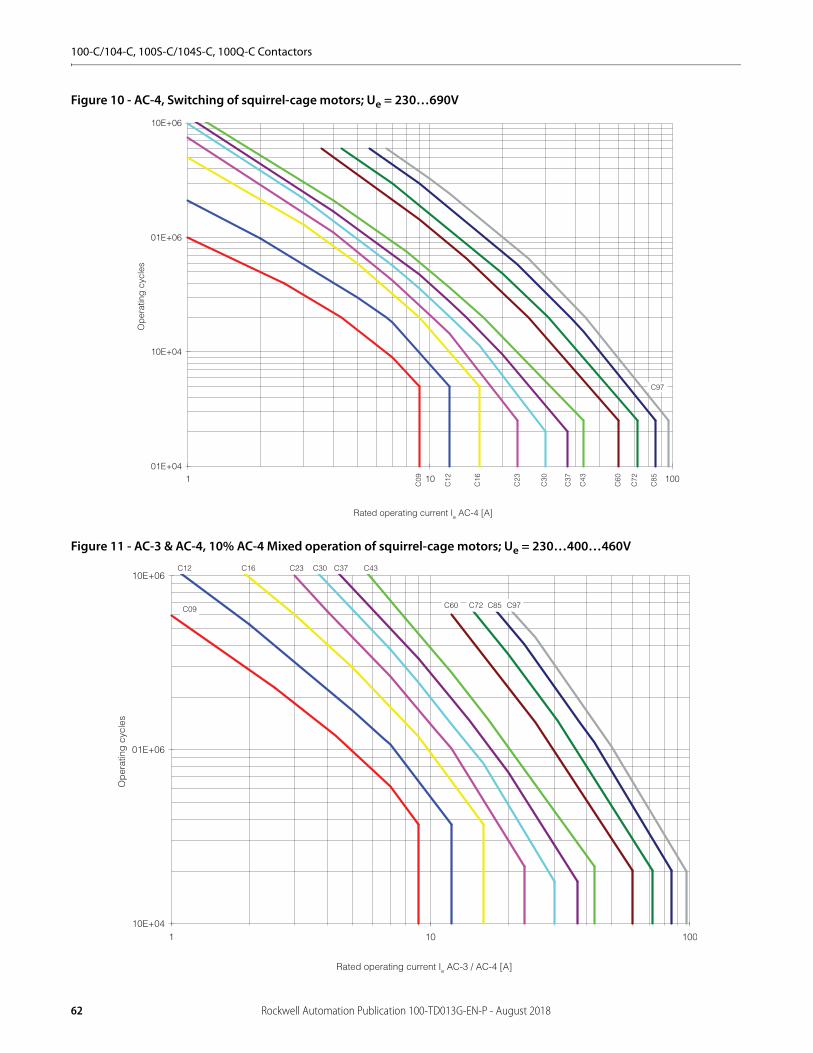
100-C/104-C, 100S-C/104S-C, 100Q-C Contactors
Figure 10 - AC-4, Switching of squirrel-cage motors; Ue = 230…690V
Figure 11 - AC-3 & AC-4, 10% AC-4 Mixed operation of squirrel-cage motors; Ue = 230…400…460V
01E+04
10E+04
01E+06
10E+06
001011
Rated operating current Ie AC-4 [A]
Op
erat
ing
cyc
les
C09
C85
C72
C60
C43
C37
C30
C23
C16
C12
C97
10E+04
01E+06
10E+06
001011
Rated operating current Ie AC-3 / AC-4 [A]
Op
erat
ing
cyc
les
C09 C85C72C60
C43C37C30C23C16C12
C97
62 Rockwell Automation Publication 100-TD013G-EN-P - August 2018

100-C/104-C, 100S-C/104S-C, 100Q-C Contactors
Figure 12 - Heavy Duty Starting and Regular Short-time Operation
1
10
100
00001000100101
Starting current / Short time current [A]
max
. Sta
rtin
g tim
e / L
oadi
ng ti
me
[s]
C09
/12/
16C
23
C30
/37
C43
C60
/72/
85
C97
Rockwell Automation Publication 100-TD013G-EN-P - August 2018 63
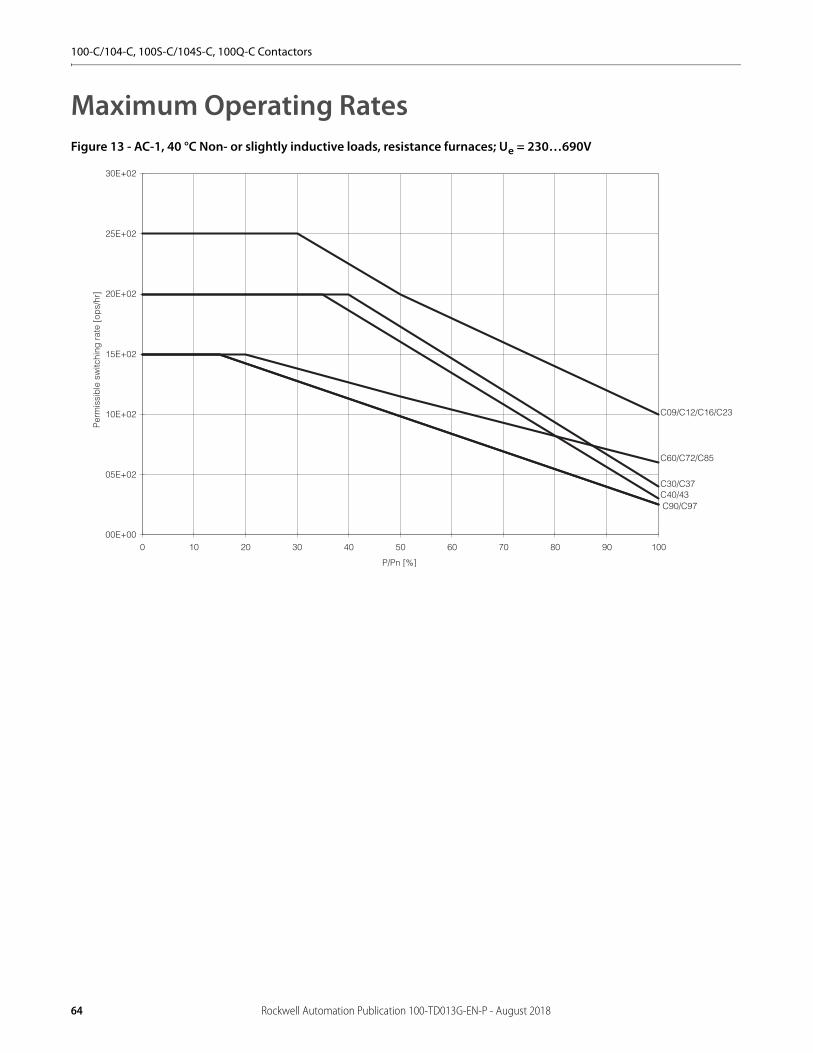
100-C/104-C, 100S-C/104S-C, 100Q-C Contactors
Maximum Operating RatesFigure 13 - AC-1, 40 °C Non- or slightly inductive loads, resistance furnaces; Ue = 230…690V
00E+00
05E+02
10E+02
15E+02
20E+02
25E+02
30E+02
0 10 20 30 40 50 60 70 80 90 100
P/Pn [%]
Per
mis
sib
le s
witc
hing
rat
e [o
ps/
hr]
C09/C12/C16/C23
C30/C37C40/43
C60/C72/C85
C90/C97
64 Rockwell Automation Publication 100-TD013G-EN-P - August 2018

100-C/104-C, 100S-C/104S-C, 100Q-C Contactors
Figure 14 - AC-2, Stepping of slip-ring motors; Ue = 230…460V
01E+02
10E+02
01E+04
0 10 20 30 40 50 60 70 80 90 100
P/Pn [%]
Per
mis
sib
le s
witc
hing
rat
e [o
ps/
hr]
C09/C12/C16
C23/C30/C37/C43
C60/C72
C85/C97
Rockwell Automation Publication 100-TD013G-EN-P - August 2018 65
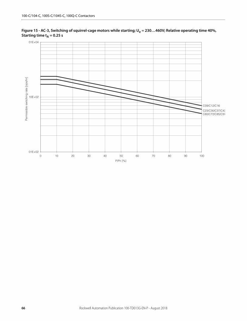
100-C/104-C, 100S-C/104S-C, 100Q-C Contactors
Figure 15 - AC-3, Switching of squirrel-cage motors while starting; Ue = 230…460V; Relative operating time 40%, Starting time tA = 0.25 s
01E+02
10E+02
01E+04
0 10 20 30 40 50 60 70 80 90 100
P/Pn [%]
Per
mis
sib
le s
witc
hing
rat
e [o
ps/
hr]
C09/C12/C16
C23/C30/C37/C43C60/C72/C85/C97
66 Rockwell Automation Publication 100-TD013G-EN-P - August 2018
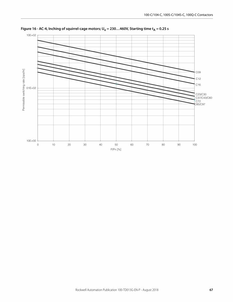
100-C/104-C, 100S-C/104S-C, 100Q-C Contactors
Figure 16 - AC-4, Inching of squirrel-cage motors; Ue = 230…460V, Starting time tA = 0.25 s
10E+00
01E+02
10E+02
0 10 20 30 40 50 60 70 80 90 100
P/Pn [%]
Per
mis
sib
le s
witc
hing
rat
e [o
ps/
hr]
C09
C12
C23/C30C37/C43/C60
C85/C97
C16
C72
Rockwell Automation Publication 100-TD013G-EN-P - August 2018 67
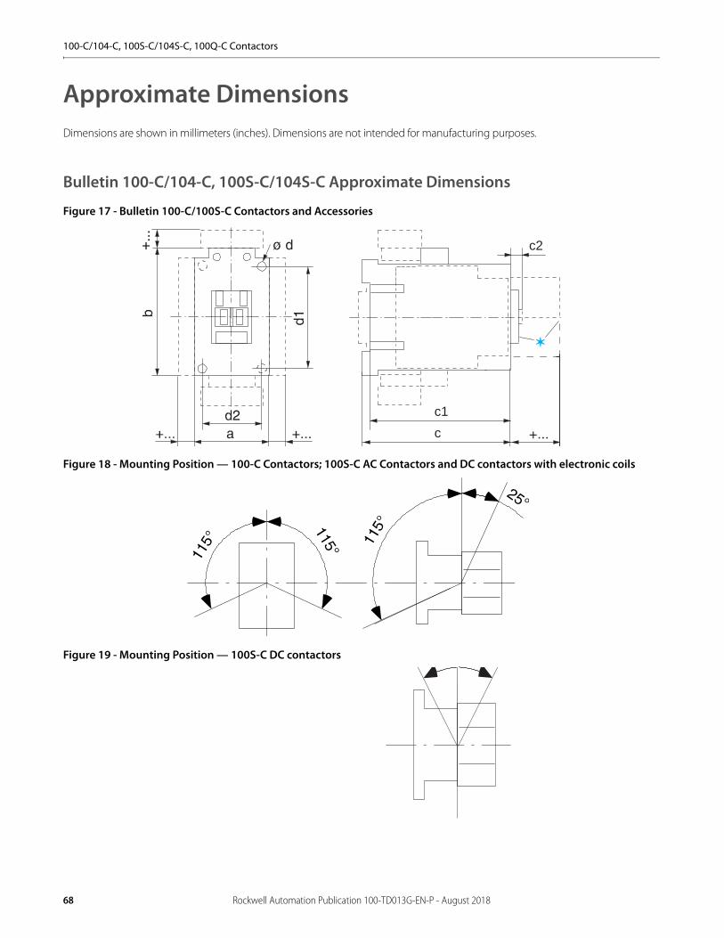
100-C/104-C, 100S-C/104S-C, 100Q-C Contactors
Approximate DimensionsDimensions are shown in millimeters (inches). Dimensions are not intended for manufacturing purposes.
Bulletin 100-C/104-C, 100S-C/104S-C Approximate Dimensions
Figure 17 - Bulletin 100-C/100S-C Contactors and Accessories
Figure 18 - Mounting Position — 100-C Contactors; 100S-C AC Contactors and DC contactors with electronic coils
Figure 19 - Mounting Position — 100S-C DC contactors
c2
c
c1
68 Rockwell Automation Publication 100-TD013G-EN-P - August 2018

100-C/104-C, 100S-C/104S-C, 100Q-C Contactors
Table 2 - AC Contactors and DC Contactors with 12V or 24V Electronic Coils
Table 3 - DC Contactors with Conventional Coils
Table 4 - DC Contactors with 36…48V, 48…72V, 110…125V, or 200…250V DC Electronic Coils
Cat. No. a b c c1 c2 d d1 d2100-C09…100-C23 45 (1-25/32) 81 (3-3/16) 80.5 (3-11/64) 75.5 (2-31/32) 6 (15/64) 2 - 4.5 (2 -3/16) 60 (2-23/64) 35 (1-3/8)
100-C30, 100-C37 45 (1-25/32) 81 (3-3/16) 97.5 (4) 92.5 (3-41/64) 6.5 (1/4) 2 - 4.5 (2 -3/16) 60 (2-23/64) 35 (1-3/8)
100-C40 59 (2-21/64) 81 (3-3/16) 100.5 (3-61/64) 95.5 (3-49/64) 6.5 (1/4) 2 - 4.5 (2 -3/16) 60 (2-23/64) 45 (1-25/32)
100-C43, 100-C55 54 (2-1/8) 81 (3-3/16) 100.5 (3-61/64) 95.5 (3-49/64) 6.5 (1/4) 2 - 4.5 (2 -3/16) 60 (2-23/64) 45 (1-25/32)
100-C60…100-C97 72 (2-53/64) 122 (4-51/64) 117 (4-39/64) 111.5 (4-25/64) 8.5 (21/64) 4 - 5.4 (4 - 7/32) 100 (3-15/16) 55 (2-11/64)
100-C90 95 (3-47/64) 122 (4-51/64) 117 (4-39/64) 111.5 (4-25/64) 8.5 (21/64) 4 - 5.4 (4 - 7/32) 100 (3-15/16) 55 (2-11/64)
100S-C09…100S-C23 45 (1-25/32) 81 (3-3/16) 119.5 (4-3/4) 114.5 (4-43/64) 6 (15/64) 2 - 4.5 (2 -3/16) 60 (2-23/64) 35 (1-3/8)
100S-C30, 100S-C37 45 (1-25/32) 81 (3-3/16) 136.5 (5-37/64) 131.6 (5-11/32) 6.5 (1/4) 2 - 4.5 (2 -3/16) 60 (2-23/64) 35 (1-3/8)
100S-C43, 100S-C55 54 (2-1/8) 81 (3-3/16) 139.5 (5-11/16) 134.6 (5-29/64) 6.5 (1/4) 2 - 4.5 (2 -3/16) 60 (2-23/64) 45 (1-25/32)
100S-C60…100S-C97 72 (2-53/64) 122 (4-51/64) 156 (6-11/32) 150.5 (6-1/8) 8.5 (21/64) 4 - 5.4 (4 - 7/32) 100 (3-15/16) 55 (2-11/64)
Cat. No. a b c c1 c2 d d1 d2100-C60D…100-C97D 72 (2-53/64) 122 (4-51/64) 117 (4-39/64) 111.5 (4-25/64) 8.5 (21/64) 4 - 5.4 (4 -7/32) 100 (3-15/16) 55 (2-11/64)
100-C90D 95 (3-47/64) 81 (3-3/16) 117 (4-39/64) 111.5 (4-25/64) 8.5 (21/64) 4 - 5.4 (4 - 7/32) 100 (3-15/16) 55 (2-11/64)
100S-C60D...100S-C97D 72 (2-53/64) 122 (4-51/64) 156 (6-11/32) 150.5 (6-1/8) 8.5 (21/64) 4 - 5.4 (4 - 7/32) 100 (3-15/16) 55 (2-11/64)
Cat. No. a b c c1 c2 d d1 d2100-C09E…100-C23E 45 (1-25/32) 105 (4-1/8) 80.5 (3-11/64) 75.5 (2-31/32) 6 (15/64) 2 - 4.5 (2 -3/16) 60 (2-23/64) 35 (1-3/8)
100-C30E…100-C37E 45 (1-25/32) 105 (4-1/8) 97.5 (4) 92.5 (3-41/64) 6.5 (1/4) 2 - 4.5 (2 -3/16) 60 (2-23/64) 35 (1-3/8)
100-C40E 59 (2-21/64) 105 (4-1/8) 100.5 (3-61/64) 95.5 (3-49/64) 6.5 (1/4) 2 - 4.5 (2 -3/16) 60 (2-23/64) 45 (1-25/32)
100-C43E…100-C55E 54 (2-1/8) 105 (4-1/8) 100.5 (3-61/64) 95.5 (3-49/64) 6.5 (1/4) 2 - 4.5 (2 -3/16) 60 (2-23/64) 45 (1-25/32)
100S-C09E…100S-C23E 45 (1-25/32) 105 (4-1/8) 119.5 (4-3/4) 114.5 (4-43/64) 6 (15/64) 2 - 4.5 (2 -3/16) 60 (2-23/64) 35 (1-3/8)
100S-C30E…100S-C37E 45 (1-25/32) 105 (4-1/8) 136.5 (5-37/64) 131.6 (5-11/32) 6.5 (1/4) 2 - 4.5 (2 -3/16) 60 (2-23/64) 35 (1-3/8)
100S-C43E…100S-C55E 54 (2-1/8) 105 (4-1/8) 139.5 (5-11/16) 134.6 (5-29/64) 6.5 (1/4) 2 - 4.5 (2 -3/16) 60 (2-23/64) 45 (1-25/32)
Rockwell Automation Publication 100-TD013G-EN-P - August 2018 69

100-C/104-C, 100S-C/104S-C, 100Q-C Contactors
Table 5 - 100-C/104-C Accessories
Table 6 - 100S-C/104S-C Accessories
Contactors with mm (inches)
Auxiliary contact block for front mounting 2- or 4-pole c/c1 + 39 (c/c1 + 1-37/64)
Auxiliary contact block for s ide mounting 1- or 2-pole a + 9 (a + 23/64)
Pneumatic Timing Module c/c1 + 58 (c/c1 + 2-23/64)
Electronic Timing Module on coil terminal side b + 24 (b + 15/16)
Mechanical Interlock on s ide of contactor a + 9 (a + 23/64)
Mechanical Latch c/c1 + 61 (c/c1 + 2-31/64)
Interface Module on coil terminal side b + 9 (b + 23/64)
Surge Suppressor on coil terminal side b + 3 (b + 1/8)
Labeling with…
label sheet + 0 (+ 0)
marking tag sheet with clear cover + 0 (+ 0)
marking tag adapter for System V4 / V5 + 5.5 (+ 7/32)
marking tag adapter for System Bul. 1492W + 5.5 (+ 7/32)
Terminal Lug Kit
100-C09…C23 b + 53 (b + 2-3/32)
100-C30…C37 b + 44 (b + 1-47/64)
100-C43…C55 b + 52 (b+ 2-3/64)
100-C60…C97 b + 99 (b + 3-7/8)
Paralleling Links
100-C09…C23 b + 78 (b + 3-1/16)
c + 9/5 (c + 3/8)
100-C30…C37 b + 85 (b + 3-11/32)
Contactors with mm (inches)
Auxiliary contact block for s ide mounting 1- or 2-pole a + 9 (a + 23/64)
Electronic Timing Module on coil terminal side b + 24 (b + 15/16)
Mechanical Interlock on side of contactor a + 9 (a + 23/64)
Interface Module on coil terminal side b + 9 (b + 23/64)
Surge Suppressor on coil terminal side b + 3 (b + 1/8)
Labeling with
label sheet + 0 (+ 0)
marking tag sheet with clear cover + 0 (+ 0)
marking tag adapter for System V4 / V5 + 5.5 (+ 7/32)
marking tag adapter for System Bul. 1492W + 5.5 (+ 7/32)
70 Rockwell Automation Publication 100-TD013G-EN-P - August 2018

100-C/104-C, 100S-C/104S-C, 100Q-C Contactors
Bulletin 100Q-C Approximate Dimensions
Figure 20 - Bulletin 100Q- Contactors
Table 7 - AC Contactors and DC Contactors with 12V or 24V Electronic Coils
Table 8 - DC Contactors with Conventional Coils
Table 9 - DC Contactors with 36…48V, 48…72V, 110…125V, or 200…250V DC Electronic Coils
Cat. No. a b c c1 c2 d d1 d2100Q-C16 45 (1-25/32) 81 (3-3/16) 119.5 (4-3/4) 114.5 (4-43/64) 6 (15/64) 2 - 4.5 (2 -3/16) 60 (2-23/64) 35 (1-3/8)
100Q-C37 45 (1-25/32) 81 (3-3/16) 136.5 (5-37/64) 131.6 (5-11/32) 6.5 (1/4) 2 - 4.5 (2 -3/16) 60 (2-23/64) 35 (1-3/8)
Cat. No. a b c c1 c2 d d1 d2100Q-C16 45 (1-25/32) 81 (3-3/16) 145.5 (5-49/64) 140.5 (5-37/64) 6 (15/64) 2 - 4.5 (2 -3/16) 60 (2-23/64) 35 (1-3/8)
100Q-C37 45 (1-25/32) 81 (3-3/16) 180.5 (7-5/32) 175.5 (6-61/64) 6.5 (1/4) 2 - 4.5 (2 -3/16) 60 (2-23/64) 35 (1-3/8)
Cat. No. a b c c1 c2 d d1 d2100Q-C16EA, -ED, or -EY 45 (1-25/32) 105 (4-1/8) 119.5 (4-3/4) 114.5 (4-43/64) 6 (15/64) 2 - 4.5 (2 -3/16) 60 (2-23/64) 35 (1-3/8)
100Q-C37EA, -ED, or -EY 45 (1-25/32) 105 (4-1/8) 136.5 (5-37/64) 131.6 (5-11/32) 6.5 (1/4) 2 - 4.5 (2 -3/16) 60 (2-23/64) 35 (1-3/8)
c2
c
c1
➊
Rockwell Automation Publication 100-TD013G-EN-P - August 2018 71
100-C/104-C, 100S-C/104S-C, 100Q-C Contactors
Notes:
72 Rockwell Automation Publication 100-TD013G-EN-P - August 2018

100-E/104-E, 100S-E/104S-E Contactors
Product Selection—100-E/104-E Contactors• 55…560 kW @ 400V• 75…900 Hp @ 460V• AC-1 ratings up to 2650 A• Compact Dimensions• Electronic Coils
– AC/DC– Wide voltage range– Low power pick-up and hold-in– Optional PLC interface
• Complete range of accessories• Environmentally friendly
The Bulletin 100-E/104-E contactor family, along with a wide range of accessories, provides the most compact and flexible contactor system available.
3-Pole AC- and DC-operated Contactors• Electronic Coils• 3 Main Contacts• Direct On-Line or Reversing
Coil voltage code and PLC interface—see page 74
Rated Operational
Current Ie [A]Ratings for switching AC motors - AC-2, AC-3 Auxiliary
Contacts Direct On-LineContactor
ReversingContactor
60 °C 40 °C kW (50 Hz) Hp (60 Hz)
AC-3 (400V)
AC-1 (690V) 220-240V 380-400V 415V 440V 500V 690V 1000V 200V 230V 460V 575V N.O. N.C. Cat No. Cat No.
116 160 37 55 55 75 75 63 55 30 40 75 100 1 1 100-E11611 (1)
(1) To order with built-in terminal lugs, add the letter "L" to the end of the catalog number (e.g. 100-E11611L)
104-E11622 (1)
146 225 45 75 75 90 90 90 75 40 50 100 125 1 1 100-E14611 (1) 104-E14622 (1)
190 275 55 90 90 110 110 132 110 50 60 125 150 1 1 100-E19011 104-E19022
205 350 55 110 110 132 132 160 132 60 75 150 200 1 1 100-E20511 104-E20522
265 400 75 132 132 160 160 200 160 75 100 200 250 1 1 100-E26511 104-E26522
305 500 90 160 160 160 200 250 185 100 125 250 300 1 1 100-E30511 104-E30522
370 600 110 200 200 200 250 315 200 125 150 300 350 1 1 100-E37011 104-E37022
400 600 110 200 220 220 250 315 220 125 150 350 400 1 1 100-E40011 104-E40022
460 700 132 250 250 250 315 355 280 150 200 400 500 1 1 100-E46011 104-E46022
580 800 160 315 355 355 400 500 355 200 250 500 600 1 1 100-E58011 104-E58022
750 1050 220 400 425 450 530 600 400 250 300 600 700 1 1 100-E75011 104-E75022
860 1350 250 475 500 560 630 800 555 — 400 800 1000 1 1 100-E86011 —
1060 1650 315 560 630 710 710 1000 600 — 450 900 1150 1 1 100-E106011 —
— 1260 — — — — — — — — — — — 1 1 100-E126011 —
— 2050 — — — — — — — — — — — 1 1 100-E205011 —
— 2650 — — — — — — — — — — — 1 1 100-E265011 —
100-E116 Contactor 100-E860 Contactor
Rockwell Automation Publication 100-TD013G-EN-P - August 2018 73

100-E/104-E, 100S-E/104S-E Contactors
Coil Voltage Codes
The Cat. No. as listed is incomplete. Select a coil voltage code from the table below to complete the Cat. No. Example: 100-E116KJ11)
Product Selection—100S-E Safety Contactors3-Pole AC- and DC-operated Safety Contactors
• Electronic Coils• 3 Main Contacts• Direct On-Line• Low-power auxiliary contact for feedback circuit• Mirror contact performance
Coil voltage code and PLC interface—see page 75
Electronic Coils V 24-60V 48-130V 100-250V 250-500V PLC Interface100-E116…100-E370 AC/DC KJ KY KD KN
100-E116…100-E370(1)
(1) When ordering coil with PLC input, the PLC input must be used
AC/DCwith PLC Input
— — ED EN
100-E400…100-E750 EJ (2) EY ED EN
100-E860…100-1060 — — ED —
100-E1260 EJ (2)
(2) 24V…60V DC only
EY ED EN
100-E2050…100-E2650 — — ED —
Rated Operational Current Ie [A] Ratings for switching AC motors - AC-2, AC-3 Auxiliary contacts per
contactorDirect On-Line
Contactor60 °C 40 °C kW (50 Hz) Hp (60 Hz)
AC-3(400V)
AC-1(690V)
220-240V 380-400V 415V 440V 500V 690V 1000V 200V 230V 460V 575V N.O. N.C. N.C.(1)
(1) The N.C. contact meets IEC 60947-4-1 Annex F requirements for mirror contact performance.
Cat No.
116 160 37 55 55 75 75 55 — 30 40 75 100 1 1 1 100S-E11612C(2)
(2) To order with built-in terminal lugs, add the letter "L" to the end of the catalog number (e.g. 100S-E11612CL)
146 225 45 75 75 90 90 90 75 40 50 100 125 1 1 1 100S-E14612C(2)
190 275 55 90 90 110 90 132 110 50 60 125 150 1 1 1 100S-E19012C
205 350 55 110 110 132 110 160 132 60 75 150 200 1 1 1 100S-E20512C
265 400 75 132 132 160 160 200 132 75 100 200 250 1 1 1 100S-E26512C
305 500 90 160 160 160 200 250 132 100 125 250 300 1 1 1 100S-E30512C
370 600 110 200 200 200 220 315 132 125 150 300 350 1 1 1 100S-E37012C
400 600 110 200 220 220 250 315 220 125 150 350 400 1 1 1 100S-E40012C
460 700 132 250 250 250 315 355 280 150 200 400 500 1 1 1 100S-E46012C
580 800 160 315 355 355 400 500 355 200 250 500 600 1 1 1 100S-E58012C
750 1050 220 400 425 450 530 600 400 250 300 600 700 1 1 1 100S-E75012C
Supply voltage
ContactorA1 A2
24V0V
COMMON
OFF_N
ONX5
1
2
3
ON
OFF
74 Rockwell Automation Publication 100-TD013G-EN-P - August 2018

100-E/104-E, 100S-E/104S-E Contactors
Coil Voltage Codes
The Cat. No. as listed is incomplete. Select a coil voltage code from the table below to complete the Cat. No. Example: 100S-E116KJ11)
Accessories
Electronic Coils V 24-60V 48-130V 100-250V 250-500V PLC Interface
100S-E116…100S-E370 AC/DC KJ KY KD KN
100S-E116…100S-E370(1)
(1) When ordering coil with PLC input, the PLC input must be used
AC/DCwith PLC Input
— — ED EN
100S-E400…100S-E750 EJ (2)
(2) 24V…60V DC only
EY ED EN
Description Connection Diagrams For Use WithStandard Auxiliary
Contact
N.O. N.C. Cat. No.
Auxiliary Contact Blocks for Side Mounting with Sequence Terminal Designations• 2-pole• Two-way numbering for right or left mounting on the contactor• Quick and easy mounting without tools• Mirror contact performance to the main contactor poles• Low power switching down to 24V 50 mA
1 1 100-E116…E370,left or right inside mounting 100-ES1-11
1 1 100-E116…E370,left or right outside mounting
100-ES2-11
Low-power Auxiliary Contact Blocks for Side Mounting with Sequence Terminal Designations (1)
• 1-pole• Two-way numbering for right or left mounting on the contactor• Quick and easy mounting without tools• Mirror contact performance to the main contactor poles• Electronic compatible, 3V 1 mA
(1) No auxiliary contacts blocks can be mounted on the outside of the 100-ES1-B* or 100-ES3-B*.
1 0100-E116…E370,
left or right inside or outside mounting
100-ES1-B10
0 1100-E116…E370,
left or right inside or outside mounting
100-ES1-B01
Auxiliary Contact Blocks for Side Mounting with Sequence Terminal Designations• 2-pole• Two-way numbering for right or left mounting on the contactor• Quick and easy mounting without tools• Mirror contact performance to the main contactor poles• Low power switching down to 24V 50 mA
1 1 100-E400…E2650,left or right inside mounting 100-ES3-11
1 1 100-E400…E2650,left or right outside mounting 100-ES4-11
Low-power Auxiliary Contact Blocks for Side Mounting with Sequence Terminal Designations (1)
• 1-pole• Two-way numbering for right or left mounting on the contactor• Quick and easy mounting without tools• Mirror contact performance to the main contactor poles• Electronic compatible, 3V 1 mA
1 0100-E400…E2650,
left or right inside or outside mounting
100-ES3-B10
0 1100-E400…E2650,
left or right inside or outside mounting
100-ES3-B01
Supply voltage
ContactorA1 A2
24V0V
COMMON
OFF_N
ONX5
1
2
3
ON
OFF
NO 14
NO 13
NC 22
NC 21NO 44 NC 32
NC 31NO 43
NO 54
NO 53
NC 62
NC 61NO 84 NC 72
NC 71NO 83
NO 18
NO 17NO 28
NO 27
NC 16
NC 15NC 26
NC 25
NO 14
NO 13
NC 22
NC 21NO 44 NC 32
NC 31NO 43
NO 54
NO 53
NC 62
NC 61NO 84 NC 72
NC 71NO 83
NO 18
NO 17NO 28
NO 27
NC 16
NC 15NC 26
NC 25
Rockwell Automation Publication 100-TD013G-EN-P - August 2018 75
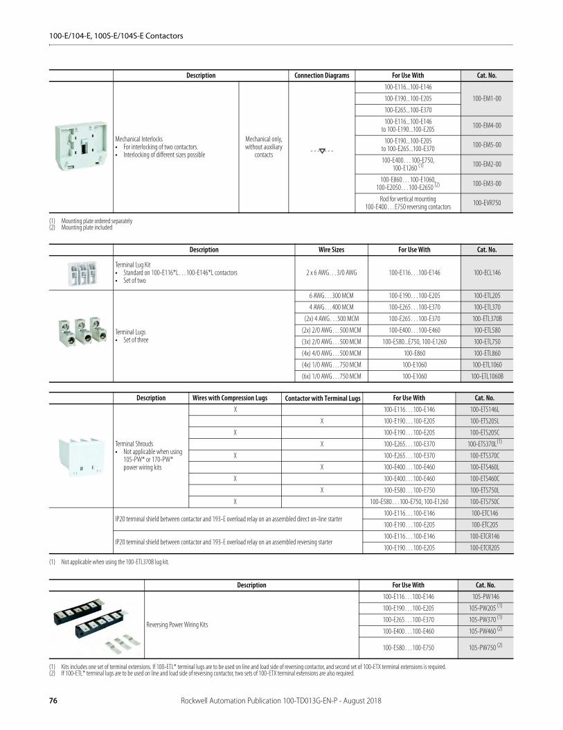
100-E/104-E, 100S-E/104S-E Contactors
Description Connection Diagrams For Use With Cat. No.
Mechanical Interlocks• For interlocking of two contactors.• Interlocking of different sizes possible
Mechanical only, without auxiliary
contacts
100-E116...100-E146
100-EM1-00100-E190...100-E205
100-E265...100-E370
100-E116...100-E146to 100-E190...100-E205 100-EM4-00
100-E190...100-E205to 100-E265...100-E370 100-EM5-00
100-E400…100-E750,100-E1260 (1)
(1) Mounting plate ordered separately
100-EM2-00
100-E860…100-E1060,100-E2050…100-E2650 (2)
(2) Mounting plate included
100-EM3-00
Rod for vertical mounting100-E400…E750 reversing contactors 100-EVR750
Description Wire Sizes For Use With Cat. No.
Terminal Lug Kit• Standard on 100-E116*L…100-E146*L contactors• Set of two
2 x 6 AWG…3/0 AWG 100-E116…100-E146 100-ECL146
Terminal Lugs• Set of three
6 AWG…300 MCM 100-E190…100-E205 100-ETL205
4 AWG…400 MCM 100-E265…100-E370 100-ETL370
(2x) 4 AWG…500 MCM 100-E265…100-E370 100-ETL370B
(2x) 2/0 AWG…500 MCM 100-E400…100-E460 100-ETL580
(3x) 2/0 AWG…500 MCM 100-E580...E750, 100-E1260 100-ETL750
(4x) 4/0 AWG…500 MCM 100-E860 100-ETL860
(4x) 1/0 AWG…750 MCM 100-E1060 100-ETL1060
(6x) 1/0 AWG…750 MCM 100-E1060 100-ETL1060B
Description Wires with Compression Lugs Contactor with Terminal Lugs For Use With Cat. No.
Terminal Shrouds• Not applicable when using
105-PW* or 170-PW* power wiring kits
X 100-E116…100-E146 100-ETS146L
X 100-E190…100-E205 100-ETS205L
X 100-E190…100-E205 100-ETS205C
X 100-E265…100-E370 100-ETS370L(1)
(1) Not applicable when using the 100-ETL370B lug kit.
X 100-E265…100-E370 100-ETS370C
X 100-E400…100-E460 100-ETS460L
X 100-E400…100-E460 100-ETS460C
X 100-E580…100-E750 100-ETS750L
X 100-E580…100-E750, 100-E1260 100-ETS750C
IP20 terminal shield between contactor and 193-E overload relay on an assembled direct on-line starter100-E116…100-E146 100-ETC146
100-E190…100-E205 100-ETC205
IP20 terminal shield between contactor and 193-E overload relay on an assembled reversing starter100-E116…100-E146 100-ETCR146
100-E190…100-E205 100-ETCR205
Description For Use With Cat. No.
Reversing Power Wiring Kits
100-E116…100-E146 105-PW146
100-E190…100-E205 105-PW205 (1)
(1) Kits includes one set of terminal extensions. If 100-ETL* terminal lugs are to be used on line and load side of reversing contactor, and second set of 100-ETX terminal extensions is required.
100-E265…100-E370 105-PW370 (1)
100-E400…100-E460 105-PW460 (2)
(2) If 100-ETL* terminal lugs are to be used on line and load side of reversing contactor, two sets of 100-ETX terminal extensions are also required.
100-E580…100-E750 105-PW750 (2)
76 Rockwell Automation Publication 100-TD013G-EN-P - August 2018

100-E/104-E, 100S-E/104S-E Contactors
Description For Use With Cat. No.
Wye-Delta Power Wiring Kits
Delta Contactor Wye Contactor Cat. No.100-E116…100-E146 100-E116…100-E146 170-PW146
100-E190…100-E205 100-E116…100-E146 170-PW190
100-E190…100-E205 100-E190…100-E205 170-PW205
100-E265…100-E370 100-E190…100-E205 170-PW265
100-E265…100-E370 100-E265…100-E370 170-PW370
100-E400…100-E460 100-E400…100-E460 170-PW460
100-E580…100-E750 100-E400…100-E460 170-PW580
100-E580…100-E750 100-E580…100-E750 170-PW750
Shorting Bars
100-E116…100-E146 170-PWY146
100-E190…100-E205 170-PWY205
100-E265…100-E370 170-PWY370
100-E400…100-E460 170-PWY460
100-E580…100-E750 170-PWY750
Description For Use With Cat. No.
For Direct On-Line Starters100-E116…100-E146 100-EMS146
100-E190…100-E205 100-EMS205
For Reversing Contactors
100-E116…100-E146 100-EMR146
100-E190…100-E205 100-EMR205
100-E265…100-E370 100-EMR370
100-E400…100-E460 100-EMR460
100-E580…100-E750 100-EMR750
For Reversing Starters100-E116…100-E146 100-EMRS146
100-E190…100-E205 100-EMRS205
Description For Use With Circuit Breaker For Use With Contactor Cat. No.
For Connection to 140G or 140MG• Connection between contactors/starters and molded case circuit
breakers.• These connection sets are solid copper bars.
140G-H, 140MG-H 100-E116…100-E146 100-PCE1
140G-I, 140MG-I 100-E116…100-E146 100-PCE2
140G-J, 140MG-J 100-E116…100-E146 100-PCE3
140G-J, 140MG-J 100-E190…100-E205 100-PCE4
140G-K, 140MG-K 100-E265…100-E370 100-PCE5
140G-M, 140MG-M 100-E400…100-E750 100-PCE6
140G-K, 140MG-K 100-E400…100-E750 100-PCE7
Description For Use With Contactor Cat. No.
Terminal Enlargements• Enlargement pieces designed to increase the width of the contactor terminal pads
in order to allow larger connections to be mounted.
100-E116…100-E146 100-ETE146
100-E190…100-E205 100-ETE205
100-E265…100-E370 100-ETE370
100-E400…100-E460 100-ETE460
100-E580…100-E750 100-ETE750
100-E1260 100-ETE1260
Description For Use With Contactor Cat. No.
Terminal Extensions• Extension pieces designed to extend the main terminals of contactors for
combined mounting of contactors and connection sets
100-E116…100-E146 100-ETX146
100-E190…100-E205 100-ETX205
100-E265…100-E370 100-ETX370
100-E400…100-E460 100-ETX460
100-E580…100-E750 100-ETX750
Rockwell Automation Publication 100-TD013G-EN-P - August 2018 77
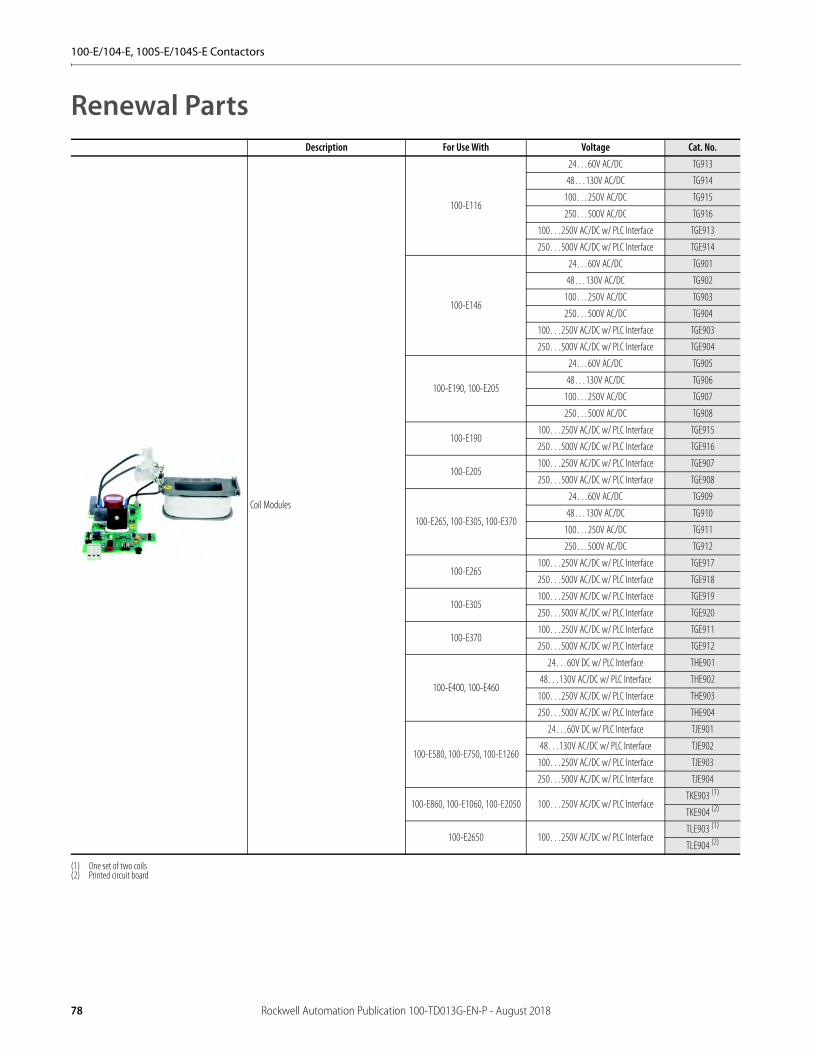
100-E/104-E, 100S-E/104S-E Contactors
Renewal PartsDescription For Use With Voltage Cat. No.
Coil Modules
100-E116
24…60V AC/DC TG913
48…130V AC/DC TG914
100…250V AC/DC TG915
250…500V AC/DC TG916
100…250V AC/DC w/ PLC Interface TGE913
250…500V AC/DC w/ PLC Interface TGE914
100-E146
24…60V AC/DC TG901
48…130V AC/DC TG902
100…250V AC/DC TG903
250…500V AC/DC TG904
100…250V AC/DC w/ PLC Interface TGE903
250…500V AC/DC w/ PLC Interface TGE904
100-E190, 100-E205
24…60V AC/DC TG905
48…130V AC/DC TG906
100…250V AC/DC TG907
250…500V AC/DC TG908
100-E190100…250V AC/DC w/ PLC Interface TGE915
250…500V AC/DC w/ PLC Interface TGE916
100-E205100…250V AC/DC w/ PLC Interface TGE907
250…500V AC/DC w/ PLC Interface TGE908
100-E265, 100-E305, 100-E370
24…60V AC/DC TG909
48…130V AC/DC TG910
100…250V AC/DC TG911
250…500V AC/DC TG912
100-E265100…250V AC/DC w/ PLC Interface TGE917
250…500V AC/DC w/ PLC Interface TGE918
100-E305100…250V AC/DC w/ PLC Interface TGE919
250…500V AC/DC w/ PLC Interface TGE920
100-E370100…250V AC/DC w/ PLC Interface TGE911
250…500V AC/DC w/ PLC Interface TGE912
100-E400, 100-E460
24…60V DC w/ PLC Interface THE901
48…130V AC/DC w/ PLC Interface THE902
100…250V AC/DC w/ PLC Interface THE903
250…500V AC/DC w/ PLC Interface THE904
100-E580, 100-E750, 100-E1260
24…60V DC w/ PLC Interface TJE901
48…130V AC/DC w/ PLC Interface TJE902
100…250V AC/DC w/ PLC Interface TJE903
250…500V AC/DC w/ PLC Interface TJE904
100-E860, 100-E1060, 100-E2050 100…250V AC/DC w/ PLC InterfaceTKE903 (1)
(1) One set of two coils
TKE904 (2)
(2) Printed circuit board
100-E2650 100…250V AC/DC w/ PLC InterfaceTLE903 (1)
TLE904 (2)
78 Rockwell Automation Publication 100-TD013G-EN-P - August 2018
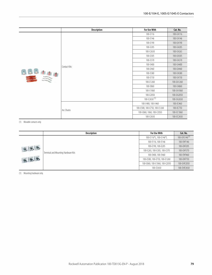
100-E/104-E, 100S-E/104S-E Contactors
Description For Use With Cat. No.
Contact Kits
100-E116 100-EA116
100-E146 100-EA146
100-E190 100-EA190
100-E205 100-EA205
100-E2650 100-EA265
100-E305 100-EA305
100-E370 100-EA370
100-E400 100-EA400
100-E460 100-EA460
100-E580 100-EA580
100-E750 100-EA750
100-E1260 100-EA1260
100-E860 100-EA860
100-E1060 100-EA1060
100-E2050 100-EA2050
100-E2650 (1)
(1) Movable contacts only
100-EA2650
Arc Chutes
100-E400, 100-E460 100-EC460
100-E580, 100-E750, 100-E1260 100-EC750
100-E860, 1060, 100-E2050 100-EC1060
100-E2650 100-EC2650
Description For Use With Cat. No.
Terminal and Mounting Hardware Kits
100-E116*L, 100-E146*L 100-EHS146(1)
(1) Mounting hardware only.
100-E116, 100-E146 100-EHF146
100-E190, 100-E205 100-EHF205
100-E265, 100-E305, 100-E370 100-EHF370
100-E400, 100-E460 100-EHF460
100-E580, 100-E750, 100-E1260 100-EHF750
100-E860, 100-E1060, 100-E2050 100-EHF2050
100-E2650 100-EHF2650
Rockwell Automation Publication 100-TD013G-EN-P - August 2018 79

100-E/104-E, 100S-E/104S-E Contactors
Specifications
Standards and Approvals
100-E, 100S-ERated Isolation Voltage Ui
IEC [V] 1000
UL, CSA [V] 600
Rated Impulse Voltage Withstand Uimp [kV] 8
Rated Voltage Ue
AC 50/60 Hz [V] 115, 200, 230, 240, 400, 415, 460 500, 575, 690, 1000
DC [V] 24, 48, 110, 220, 440
Electromagnetic compatibility IEC 60947-1 - Environment A
Insulation Class of the Coil Class F per IEC 60947-4-1
Rated coil frequency AC 50/60 Hz, DC
Ambient TemperatureStorage [°C] -40…+70
Operation at rated voltage [°C] -40…+70
Max. Altitude of Installation Site [m] 3000
Climatic Withstand100-E116…100-E370 IEC 60068-2-30 Test Db & IEC 60068-2-2 test Bd & IEC 60068-2-1 test Ab (report 1314369)
100-E400…100-E2650 IEC 60068-2-2 test Ba & Bb & IEC 60068-2-1 test Aa&Ab, IEC 60068-2-30
Resistance to Shock IEC 60068-2-27
Resistance to Vibration IEC 60068-2-6
Protection ClassContactor main contacts IP00
Contactor coil terminals P2X (in connected state)
Auxiliary contacts P2X (in connected state)
Functional Safety Data (100S-E116…100S-E750)(1)
(1) Usable for ISO 13849-1 and IEC 62061. Data is based on the B10 value given and: - Mission time/Proof test interval of 20 years.
100(S)-E116…100(S)-E370 B10: 1.0E+06 operations at 50% max. AC-3 load; failure ratio: 75% failure to open, 25% failure to close
100(S)-E116…100(S)-E370 B10: 5.0E+06 operations, mechanical only; failure ratio: 50% failure to open, 50% failure to close
100(S)-E400…100(S)-E750 B10: 5.0E+05 operations at 50% max. AC-3 load; failure ratio: 75% failure to open, 25% failure to close
100(S)-E400…100(S)-E460 B10: 3.0E+06 operations, mechanical only; failure ratio: 50% failure to open, 50% failure to close
100(S)-E570…100(S)-E750 B10: 9.0E+05 operations, mechanical only; failure ratio: 50% failure to open, 50% failure to close
Standards
IEC/EN 60947-1, Low-voltage switchgear and controlgear;IEC/EN 60947-4-1, Low-voltage switchgear and controlgear, Contactors and motor-starters;IEC/EN 60947-5-1, Low-voltage switchgear and controlgear, Control circuit devices and switching elements;UL 60947-4-1, Industrial Control Equipment (USA); CSA C22.2 No. 60947-4-1 Industrial Control Equipment (Canada).
Mechanically Linked Contacts: IEC 60947-5-1, Annex L
Mirror Contacts: IEC 60947-4-1, Annex F 100/100S-E116…100/100S-E750 with all 100-ES* side mounted N.C. auxiliary contacts
Approvals
ULcULus, File No. E41850 / E196120 (contactors, reversing contactors)
CSA
CCC √
EAC √
RCM √
RINA √
ABS √
KC √
Certifications
CE √
SUVA √
SEMI-F47 Conditions of use on request
80 Rockwell Automation Publication 100-TD013G-EN-P - August 2018
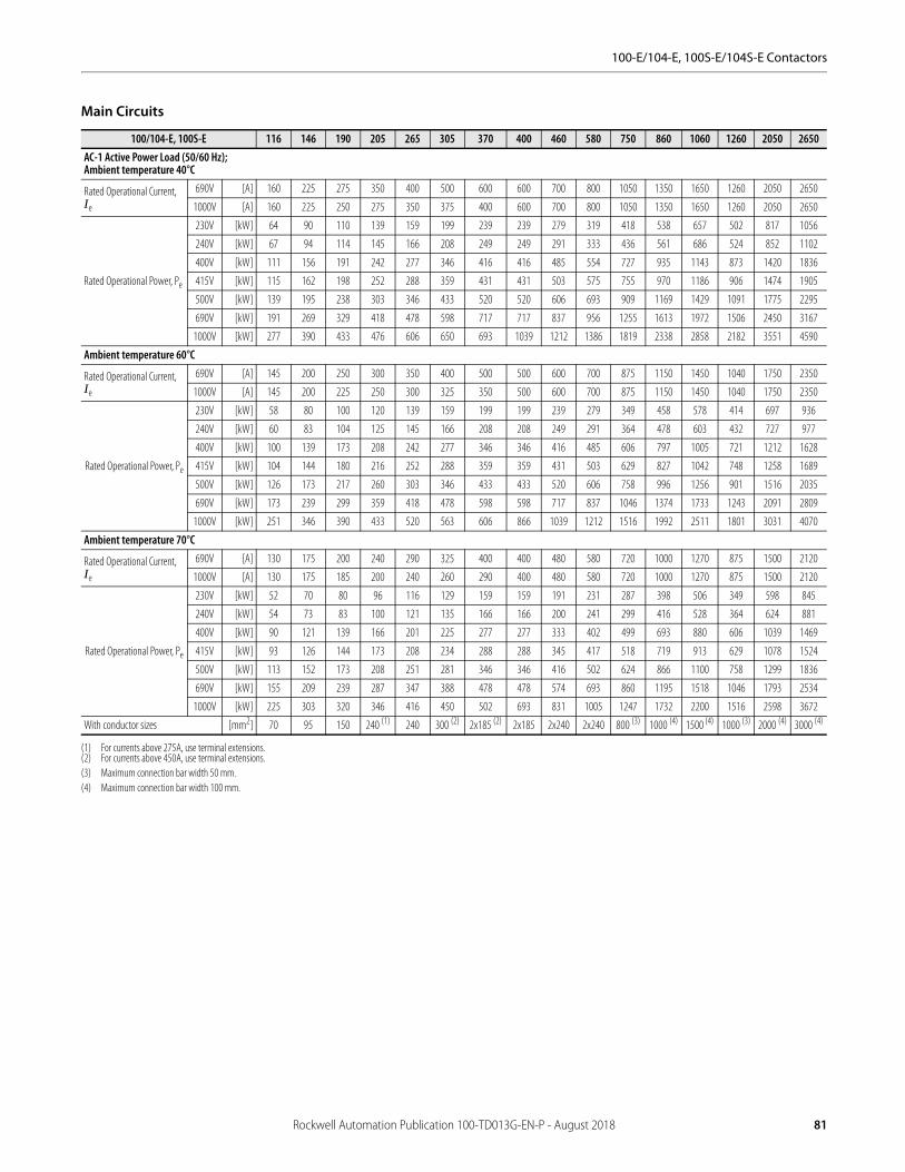
100-E/104-E, 100S-E/104S-E Contactors
Main Circuits
100/104-E, 100S-E 116 146 190 205 265 305 370 400 460 580 750 860 1060 1260 2050 2650AC-1 Active Power Load (50/60 Hz);Ambient temperature 40°C
Rated Operational Current, Ie
690V [A] 160 225 275 350 400 500 600 600 700 800 1050 1350 1650 1260 2050 2650
1000V [A] 160 225 250 275 350 375 400 600 700 800 1050 1350 1650 1260 2050 2650
Rated Operational Power, Pe
230V [kW] 64 90 110 139 159 199 239 239 279 319 418 538 657 502 817 1056
240V [kW] 67 94 114 145 166 208 249 249 291 333 436 561 686 524 852 1102
400V [kW] 111 156 191 242 277 346 416 416 485 554 727 935 1143 873 1420 1836
415V [kW] 115 162 198 252 288 359 431 431 503 575 755 970 1186 906 1474 1905
500V [kW] 139 195 238 303 346 433 520 520 606 693 909 1169 1429 1091 1775 2295
690V [kW] 191 269 329 418 478 598 717 717 837 956 1255 1613 1972 1506 2450 3167
1000V [kW] 277 390 433 476 606 650 693 1039 1212 1386 1819 2338 2858 2182 3551 4590
Ambient temperature 60°C
Rated Operational Current, Ie
690V [A] 145 200 250 300 350 400 500 500 600 700 875 1150 1450 1040 1750 2350
1000V [A] 145 200 225 250 300 325 350 500 600 700 875 1150 1450 1040 1750 2350
Rated Operational Power, Pe
230V [kW] 58 80 100 120 139 159 199 199 239 279 349 458 578 414 697 936
240V [kW] 60 83 104 125 145 166 208 208 249 291 364 478 603 432 727 977
400V [kW] 100 139 173 208 242 277 346 346 416 485 606 797 1005 721 1212 1628
415V [kW] 104 144 180 216 252 288 359 359 431 503 629 827 1042 748 1258 1689
500V [kW] 126 173 217 260 303 346 433 433 520 606 758 996 1256 901 1516 2035
690V [kW] 173 239 299 359 418 478 598 598 717 837 1046 1374 1733 1243 2091 2809
1000V [kW] 251 346 390 433 520 563 606 866 1039 1212 1516 1992 2511 1801 3031 4070
Ambient temperature 70°C
Rated Operational Current, Ie
690V [A] 130 175 200 240 290 325 400 400 480 580 720 1000 1270 875 1500 2120
1000V [A] 130 175 185 200 240 260 290 400 480 580 720 1000 1270 875 1500 2120
Rated Operational Power, Pe
230V [kW] 52 70 80 96 116 129 159 159 191 231 287 398 506 349 598 845
240V [kW] 54 73 83 100 121 135 166 166 200 241 299 416 528 364 624 881
400V [kW] 90 121 139 166 201 225 277 277 333 402 499 693 880 606 1039 1469
415V [kW] 93 126 144 173 208 234 288 288 345 417 518 719 913 629 1078 1524
500V [kW] 113 152 173 208 251 281 346 346 416 502 624 866 1100 758 1299 1836
690V [kW] 155 209 239 287 347 388 478 478 574 693 860 1195 1518 1046 1793 2534
1000V [kW] 225 303 320 346 416 450 502 693 831 1005 1247 1732 2200 1516 2598 3672
With conductor sizes [mm2] 70 95 150 240 (1)
(1) For currents above 275A, use terminal extensions.
240 300 (2)
(2) For currents above 450A, use terminal extensions.
2x185 (2) 2x185 2x240 2x240 800 (3)
(3) Maximum connection bar width 50 mm.
1000 (4)
(4) Maximum connection bar width 100 mm.
1500 (4) 1000 (3) 2000 (4) 3000 (4)
Rockwell Automation Publication 100-TD013G-EN-P - August 2018 81

100-E/104-E, 100S-E/104S-E Contactors
100/104-E, 100S-E 116 146 190 205 265 305 370 400 460 580 750 860 1060 1260 2050 2650Switching of 3-phase Motors; (50 Hz)Ambient temperature 60°C, AC-2, AC-3
Rated Operational Current, Ie
220-240V [A] 116 146 190 205 265 305 370 400 460 580 750 860 1060 — — —
380-400V [A] 116 146 190 205 265 305 370 400 460 580 750 860 1060 — — —
415V [A] 116 146 190 205 265 305 370 400 460 580 750 860 1060 — — —
440V [A] 116 146 190 205 265 305 370 400 460 580 750 860 1060 — — —
500V [A] 110 130 156 185 250 290 350 400 460 580 750 860 970 — — —
690V [A] 66 93 135 165 250 290 315 350 400 500 650 800 970 — — —
1000V [A] 46 60 85 100 113 131 141 155 200 250 300 375 400 — — —
Rated Operational Power, Pe
220-240V [kW] 37 45 55 55 75 90 110 110 132 160 220 250 315 — — —
380-400V [kW] 55 75 90 110 132 160 200 200 250 315 400 475 560 — — —
415V [kW] 55 75 90 110 132 160 200 220 250 355 425 500 630 — — —
440V [kW] 75 90 110 132 160 160 200 220 250 355 450 560 710 — — —
500V [kW] 75 90 110 132 160 200 250 250 315 400 530 630 710 — — —
690V [kW] 63 90 132 160 200 250 315 315 355 500 600 800 1000 — — —
1000V [kW] 55 75 110 132 160 185 200 220 280 355 400 555 600 — — —
Load Carrying Capacity per UL/CSAGeneral Purpose Current (enclosed) [A] 160 200 250 300 350 400 520 550 650 750 900 1350 1650 1210 2100 2700
Rated Power (enclosed), 3-phase
200V [A] 92 120 150 177 221 285 359 359 414 552 692 954 1030 — — —
230V [A] 104 130 154 192 248 312 360 360 480 604 722 954 1030 — — —
460V [A] 96 124 156 180 240 302 361 414 477 590 722 954 1030 — — —
575V [A] 99 125 144 192 242 289 336 382 472 578 672 944 1050 — — —
200V [Hp] 30 40 50 60 75 100 125 125 150 200 250 — — — — —
230V [Hp] 40 50 60 75 100 125 150 150 200 250 300 400 450 — — —
460V [Hp] 75 100 125 150 200 250 300 350 400 500 600 800 900 — — —
575V [Hp] 100 125 150 200 250 300 350 400 500 600 700 1000 1150 — — —
Rated Power (enclosed), with 3 poles in series
260V DC [A] 160 200 — — — — — — — — — — — — — —
300V DC [A] — — 230 250 — — — — — — — — — — — —
340V DC [A] — — — — 350 400 520 — — — — — — — — —
600V DC [A] — — — — — — — 550 650 750 900 1050 1350 1210 1900 —
82 Rockwell Automation Publication 100-TD013G-EN-P - August 2018

100-E/104-E, 100S-E/104S-E Contactors
100/104-E, 100S-E 116 146 190 205 265 305 370 400 460 580 750 860 1060 1260 2050 2650Switching of 3-phase Motors, (50Hz); Ambient temperature 60°C, AC-4
Rated Operational Current, Ie
230V [A] 84 103 128 156 195 230 280 307 377 — — — — — — —
240V [A] 84 103 128 156 195 230 280 307 377 — — — — — — —
400V [A] 84 103 128 156 195 230 280 307 377 — — — — — — —
415V [A] 84 103 128 156 195 230 280 307 377 — — — — — — —
500V [A] 84 103 128 156 195 230 280 307 377 — — — — — — —
690V [A] 66 80 93 104 153 162 188 334 350 — — — — — — —
1000V [A] 40 48 72 85 90 95 100 141 155 — — — — — — —
Rated Operational Power, Pe
230V [kW] 25 32 40 50 55 75 90 90 110 — — — — — — —
240V [kW] 25 32 40 50 63 75 90 100 125 — — — — — — —
400V [kW] 45 55 63 80 110 132 160 160 200 — — — — — — —
415V [kW] 45 55 63 90 110 132 160 160 220 — — — — — — —
500V [kW] 55 63 90 110 132 160 200 220 250 — — — — — — —
690V [kW] 63 75 90 100 150 160 185 315 335 — — — — — — —
1000V [kW] 55 63 100 110 125 132 132 200 220 — — — — — — —
AC-4 at approximately 200,000 operations
Rated Operational Current, Ie
230V [A] 38 38 49 55 73 89 100 118 135 — — — — — — —
240V [A] 38 38 49 55 73 89 100 118 135 — — — — — — —
400/415V [A] 38 38 49 55 73 89 100 118 135 — — — — — — —
500V [A] 33 33 37 44 53 59 68 78 89 — — — — — — —
690V [A] 33 33 37 44 53 59 68 78 89 — — — — — — —
1000V [A] — — — — — — — — — — — — — — — —
Rated Operational Power, Pe
230V [kW] 11 11 13 15 22 25 30 37 40 — — — — — — —
240V [kW] 11 11 15 15 22 25 32 37 45 — — — — — — —
400V [kW] 20 20 25 30 40 50 55 63 75 — — — — — — —
415V [kW] 20 20 25 30 40 50 55 63 75 — — — — — — —
500V [kW] 22 22 25 30 37 40 45 55 63 — — — — — — —
690V [kW] 30 30 32 40 50 55 63 75 80 — — — — — — —
1000V [kW] — — — — — — — — — — — — — — — —
Max. switching frequency Ops/h 150 150 150 150 150 150 150 60 60 — — — — — — —
Wye-Delta (60 Hz)200V [Hp] 50 60 75 100 125 150 200 200 250 — — — — — — —
230V [Hp] 60 75 100 125 150 200 250 250 350 450 500 — — — — —
460V [Hp] 125 150 200 250 350 450 500 500 600 800 — — — — — —
575V [Hp] 150 200 250 300 450 500 600 600 700 1000 — — — — — —
Rockwell Automation Publication 100-TD013G-EN-P - August 2018 83
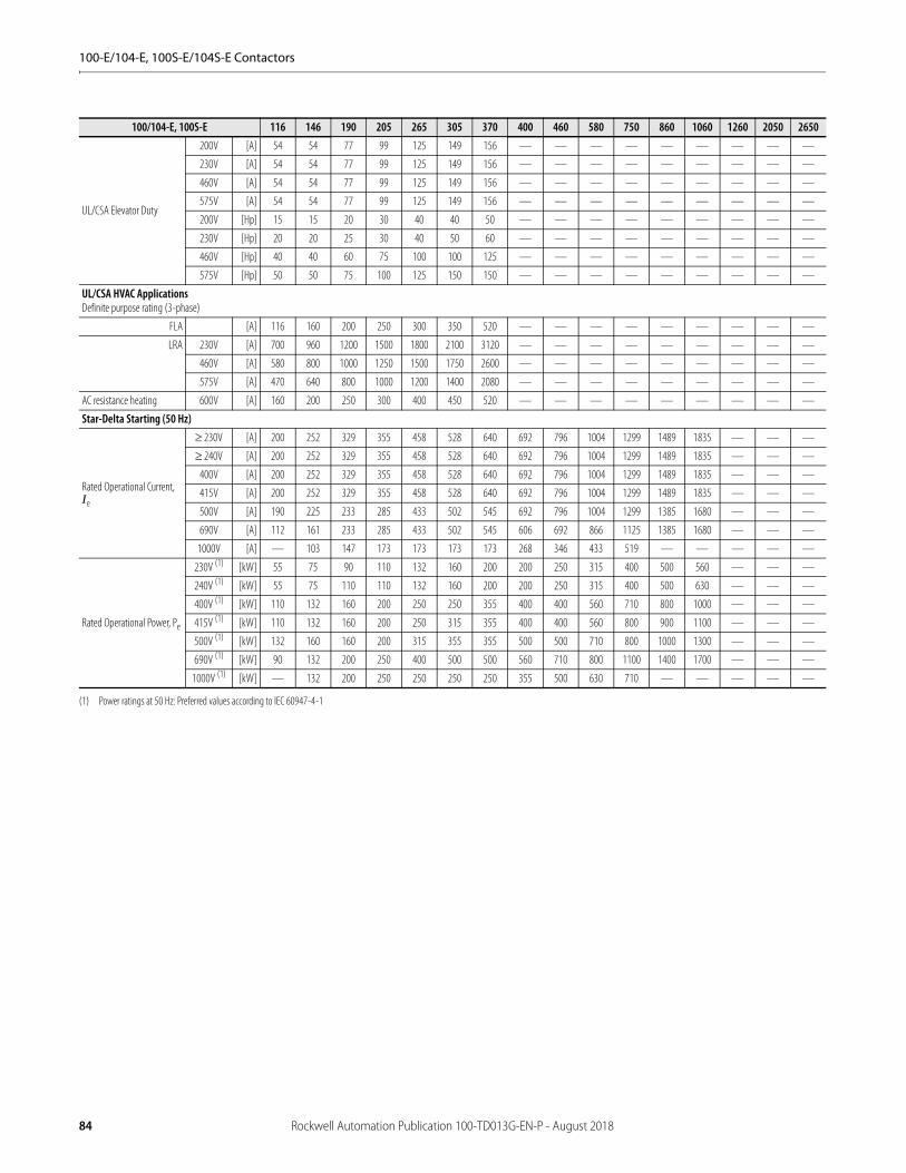
100-E/104-E, 100S-E/104S-E Contactors
100/104-E, 100S-E 116 146 190 205 265 305 370 400 460 580 750 860 1060 1260 2050 2650
UL/CSA Elevator Duty
200V [A] 54 54 77 99 125 149 156 — — — — — — — — —
230V [A] 54 54 77 99 125 149 156 — — — — — — — — —
460V [A] 54 54 77 99 125 149 156 — — — — — — — — —
575V [A] 54 54 77 99 125 149 156 — — — — — — — — —
200V [Hp] 15 15 20 30 40 40 50 — — — — — — — — —
230V [Hp] 20 20 25 30 40 50 60 — — — — — — — — —
460V [Hp] 40 40 60 75 100 100 125 — — — — — — — — —
575V [Hp] 50 50 75 100 125 150 150 — — — — — — — — —
UL/CSA HVAC ApplicationsDefinite purpose rating (3-phase)
FLA [A] 116 160 200 250 300 350 520 — — — — — — — — —
LRA 230V [A] 700 960 1200 1500 1800 2100 3120 — — — — — — — — —
460V [A] 580 800 1000 1250 1500 1750 2600 — — — — — — — — —
575V [A] 470 640 800 1000 1200 1400 2080 — — — — — — — — —
AC resistance heating 600V [A] 160 200 250 300 400 450 520 — — — — — — — — —
Star-Delta Starting (50 Hz)
Rated Operational Current, Ie
230V [A] 200 252 329 355 458 528 640 692 796 1004 1299 1489 1835 — — —
240V [A] 200 252 329 355 458 528 640 692 796 1004 1299 1489 1835 — — —
400V [A] 200 252 329 355 458 528 640 692 796 1004 1299 1489 1835 — — —
415V [A] 200 252 329 355 458 528 640 692 796 1004 1299 1489 1835 — — —
500V [A] 190 225 233 285 433 502 545 692 796 1004 1299 1385 1680 — — —
690V [A] 112 161 233 285 433 502 545 606 692 866 1125 1385 1680 — — —
1000V [A] — 103 147 173 173 173 173 268 346 433 519 — — — — —
Rated Operational Power, Pe
230V (1)
(1) Power ratings at 50 Hz: Preferred values according to IEC 60947-4-1
[kW] 55 75 90 110 132 160 200 200 250 315 400 500 560 — — —
240V (1) [kW] 55 75 110 110 132 160 200 200 250 315 400 500 630 — — —
400V (1) [kW] 110 132 160 200 250 250 355 400 400 560 710 800 1000 — — —
415V (1) [kW] 110 132 160 200 250 315 355 400 400 560 800 900 1100 — — —
500V (1) [kW] 132 160 160 200 315 355 355 500 500 710 800 1000 1300 — — —
690V (1) [kW] 90 132 200 250 400 500 500 560 710 800 1100 1400 1700 — — —
1000V (1) [kW] — 132 200 250 250 250 250 355 500 630 710 — — — — —
84 Rockwell Automation Publication 100-TD013G-EN-P - August 2018
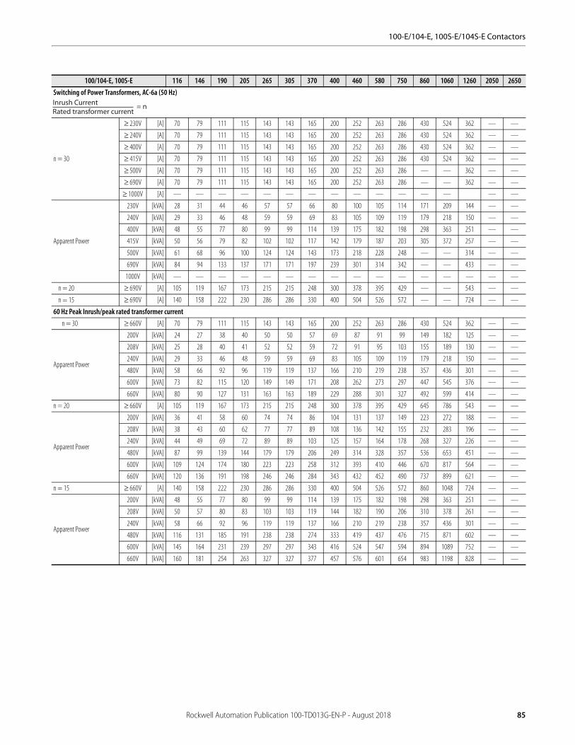
100-E/104-E, 100S-E/104S-E Contactors
100/104-E, 100S-E 116 146 190 205 265 305 370 400 460 580 750 860 1060 1260 2050 2650Switching of Power Transformers, AC-6a (50 Hz)
n = 30
230V [A] 70 79 111 115 143 143 165 200 252 263 286 430 524 362 — —
240V [A] 70 79 111 115 143 143 165 200 252 263 286 430 524 362 — —
400V [A] 70 79 111 115 143 143 165 200 252 263 286 430 524 362 — —
415V [A] 70 79 111 115 143 143 165 200 252 263 286 430 524 362 — —
500V [A] 70 79 111 115 143 143 165 200 252 263 286 — — 362 — —
690V [A] 70 79 111 115 143 143 165 200 252 263 286 — — 362 — —
1000V [A] — — — — — — — — — — — — — — —
Apparent Power
230V [kVA] 28 31 44 46 57 57 66 80 100 105 114 171 209 144 — —
240V [kVA] 29 33 46 48 59 59 69 83 105 109 119 179 218 150 — —
400V [kVA] 48 55 77 80 99 99 114 139 175 182 198 298 363 251 — —
415V [kVA] 50 56 79 82 102 102 117 142 179 187 203 305 372 257 — —
500V [kVA] 61 68 96 100 124 124 143 173 218 228 248 — — 314 — —
690V [kVA] 84 94 133 137 171 171 197 239 301 314 342 — — 433 — —
1000V [kVA] — — — — — — — — — — — — — — — —
n = 20 690V [A] 105 119 167 173 215 215 248 300 378 395 429 — — 543 — —
n = 15 690V [A] 140 158 222 230 286 286 330 400 504 526 572 — — 724 — —
60 Hz Peak Inrush/peak rated transformer currentn = 30 660V [A] 70 79 111 115 143 143 165 200 252 263 286 430 524 362 — —
Apparent Power
200V [kVA] 24 27 38 40 50 50 57 69 87 91 99 149 182 125 — —
208V [kVA] 25 28 40 41 52 52 59 72 91 95 103 155 189 130 — —
240V [kVA] 29 33 46 48 59 59 69 83 105 109 119 179 218 150 — —
480V [kVA] 58 66 92 96 119 119 137 166 210 219 238 357 436 301 — —
600V [kVA] 73 82 115 120 149 149 171 208 262 273 297 447 545 376 — —
660V [kVA] 80 90 127 131 163 163 189 229 288 301 327 492 599 414 — —
n = 20 660V [A] 105 119 167 173 215 215 248 300 378 395 429 645 786 543 — —
Apparent Power
200V [kVA] 36 41 58 60 74 74 86 104 131 137 149 223 272 188 — —
208V [kVA] 38 43 60 62 77 77 89 108 136 142 155 232 283 196 — —
240V [kVA] 44 49 69 72 89 89 103 125 157 164 178 268 327 226 — —
480V [kVA] 87 99 139 144 179 179 206 249 314 328 357 536 653 451 — —
600V [kVA] 109 124 174 180 223 223 258 312 393 410 446 670 817 564 — —
660V [kVA] 120 136 191 198 246 246 284 343 432 452 490 737 899 621 — —
n = 15 660V [A] 140 158 222 230 286 286 330 400 504 526 572 860 1048 724 — —
Apparent Power
200V [kVA] 48 55 77 80 99 99 114 139 175 182 198 298 363 251 — —
208V [kVA] 50 57 80 83 103 103 119 144 182 190 206 310 378 261 — —
240V [kVA] 58 66 92 96 119 119 137 166 210 219 238 357 436 301 — —
480V [kVA] 116 131 185 191 238 238 274 333 419 437 476 715 871 602 — —
600V [kVA] 145 164 231 239 297 297 343 416 524 547 594 894 1089 752 — —
660V [kVA] 160 181 254 263 327 327 377 457 576 601 654 983 1198 828 — —
Inrush CurrentRated transformer current
= n
Rockwell Automation Publication 100-TD013G-EN-P - August 2018 85
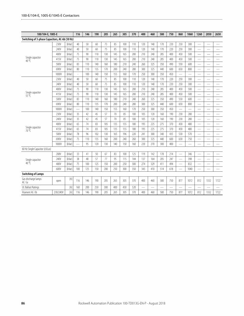
100-E/104-E, 100S-E/104S-E Contactors
100/104-E, 100S-E 116 146 190 205 265 305 370 400 460 580 750 860 1060 1260 2050 2650Switching of 3-phase Capacitors, AC-6b (50 Hz)
Single capacitor40 °C
230V [kVar] 40 50 60 75 85 100 110 120 140 170 220 250 300 — — —
240V [kVar] 40 50 60 75 85 100 110 120 140 170 220 250 300 — — —
400V [kVar] 75 90 110 130 145 165 200 210 240 285 400 450 500 — — —
415V [kVar] 75 90 110 130 145 165 200 210 240 285 400 450 500 — — —
500V [kVar] 83 110 140 160 180 210 240 260 325 350 490 550 600 — — —
690V [kVar] 80 110 135 170 200 240 280 300 325 440 600 650 800 — — —
1000V [kVar] - 100 140 150 155 160 170 250 300 350 450 — — — — —
Single capacitor55 °C
230V [kVar] 40 50 60 75 85 100 110 120 140 170 220 250 300 — — —
240V [kVar] 40 50 60 75 85 100 110 120 140 170 220 250 300 — — —
400V [kVar] 75 90 110 130 145 165 200 210 240 285 400 450 500 — — —
415V [kVar] 75 90 110 130 145 165 200 210 240 285 400 450 500 — — —
500V [kVar] 83 110 140 160 180 210 240 260 325 350 490 550 600 — — —
690V [kVar] 80 110 135 170 200 240 280 300 325 440 600 650 800 — — —
1000V [kVar] — 100 140 150 155 160 170 250 300 350 450 — — — — —
Single capacitor70 °C
230V [kVar] 35 42 45 57 70 85 100 105 120 160 190 230 280 — — —
240V [kVar] 35 42 45 57 70 85 100 105 120 160 190 230 280 — — —
400V [kVar] 65 74 83 105 135 155 180 195 225 275 370 430 480 — — —
415V [kVar] 65 74 83 105 135 155 180 195 225 275 370 430 480 — — —
500V [kVar] 78 96 102 130 165 196 220 241 300 340 435 530 570 — — —
690V [kVar] 75 110 135 160 200 240 260 300 325 440 600 630 750 — — —
1000V [kVar] — 95 120 130 140 150 160 220 270 300 400 — — — — —
60 Hz Single Capacitor (cULus)
Single capacitor40 °C
208V [kVar] 33 41 50 67 83 100 125 119 142 178 214 — 346 — — —
240V [kVar] 38 48 57 77 95 115 144 137 164 205 247 — 398 — — —
480V [kVar] 75 100 125 150 200 250 300 274 329 411 494 — 832 — — —
600V [kVar] 100 125 150 200 250 300 350 343 410 514 618 — 1040 — — —
Switching of LampsGas discharge lampsAC-5a open [A] 116 146 190 205 265 305 370 400 460 580 750 877 1072 812 1332 1722
UL Ballast Ratings [A] 160 200 250 300 400 450 520 — — — — — — — — —
Filament AC-5b 230/240V [A] 116 146 190 205 265 305 370 400 460 580 750 877 1072 812 1332 1722
86 Rockwell Automation Publication 100-TD013G-EN-P - August 2018
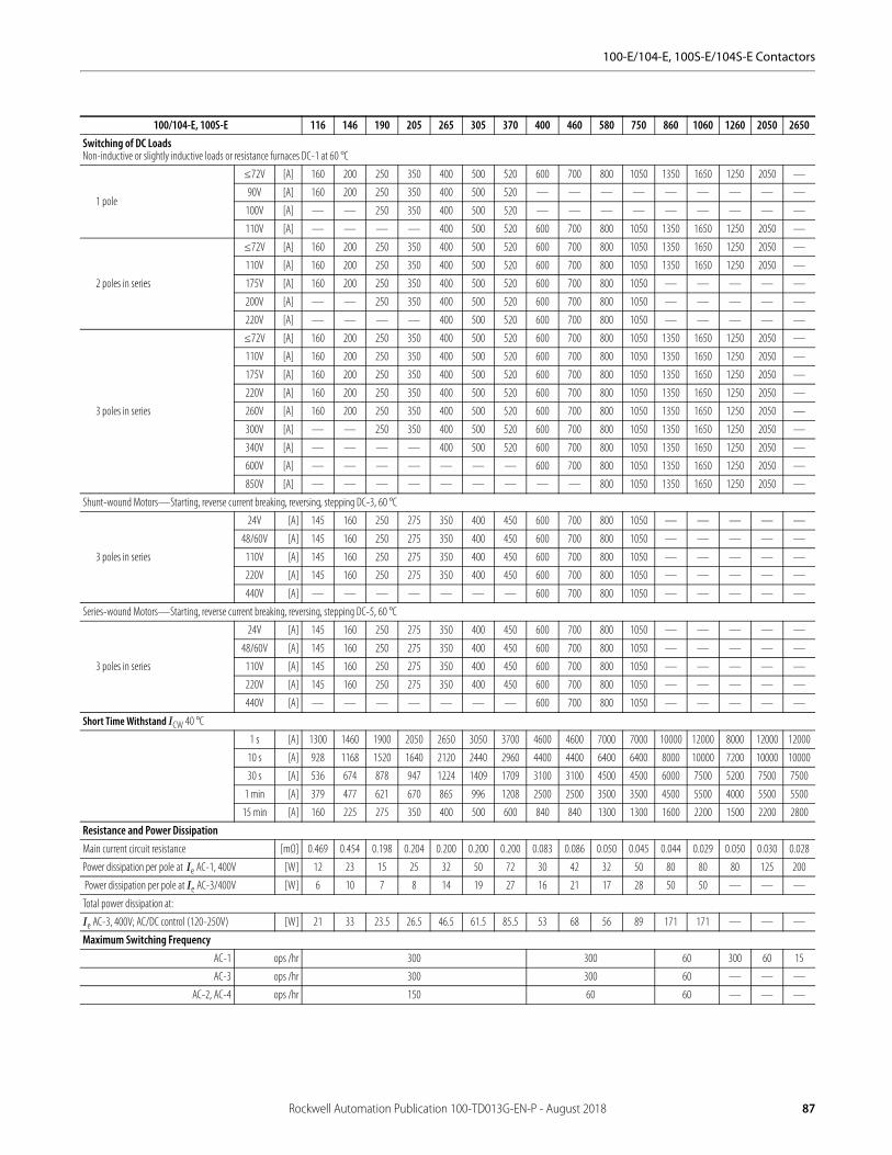
100-E/104-E, 100S-E/104S-E Contactors
100/104-E, 100S-E 116 146 190 205 265 305 370 400 460 580 750 860 1060 1260 2050 2650Switching of DC LoadsNon-inductive or slightly inductive loads or resistance furnaces DC-1 at 60 °C
1 pole
≤72V [A] 160 200 250 350 400 500 520 600 700 800 1050 1350 1650 1250 2050 —
90V [A] 160 200 250 350 400 500 520 — — — — — — — — —
100V [A] — — 250 350 400 500 520 — — — — — — — — —
110V [A] — — — — 400 500 520 600 700 800 1050 1350 1650 1250 2050 —
2 poles in series
≤72V [A] 160 200 250 350 400 500 520 600 700 800 1050 1350 1650 1250 2050 —
110V [A] 160 200 250 350 400 500 520 600 700 800 1050 1350 1650 1250 2050 —
175V [A] 160 200 250 350 400 500 520 600 700 800 1050 — — — — —
200V [A] — — 250 350 400 500 520 600 700 800 1050 — — — — —
220V [A] — — — — 400 500 520 600 700 800 1050 — — — — —
3 poles in series
≤72V [A] 160 200 250 350 400 500 520 600 700 800 1050 1350 1650 1250 2050 —
110V [A] 160 200 250 350 400 500 520 600 700 800 1050 1350 1650 1250 2050 —
175V [A] 160 200 250 350 400 500 520 600 700 800 1050 1350 1650 1250 2050 —
220V [A] 160 200 250 350 400 500 520 600 700 800 1050 1350 1650 1250 2050 —
260V [A] 160 200 250 350 400 500 520 600 700 800 1050 1350 1650 1250 2050 —
300V [A] — — 250 350 400 500 520 600 700 800 1050 1350 1650 1250 2050 —
340V [A] — — — — 400 500 520 600 700 800 1050 1350 1650 1250 2050 —
600V [A] — — — — — — — 600 700 800 1050 1350 1650 1250 2050 —
850V [A] — — — — — — — — — 800 1050 1350 1650 1250 2050 —
Shunt-wound Motors—Starting, reverse current breaking, reversing, stepping DC-3, 60 °C
3 poles in series
24V [A] 145 160 250 275 350 400 450 600 700 800 1050 — — — — —
48/60V [A] 145 160 250 275 350 400 450 600 700 800 1050 — — — — —
110V [A] 145 160 250 275 350 400 450 600 700 800 1050 — — — — —
220V [A] 145 160 250 275 350 400 450 600 700 800 1050 — — — — —
440V [A] — — — — — — — 600 700 800 1050 — — — — —
Series-wound Motors—Starting, reverse current breaking, reversing, stepping DC-5, 60 °C
3 poles in series
24V [A] 145 160 250 275 350 400 450 600 700 800 1050 — — — — —
48/60V [A] 145 160 250 275 350 400 450 600 700 800 1050 — — — — —
110V [A] 145 160 250 275 350 400 450 600 700 800 1050 — — — — —
220V [A] 145 160 250 275 350 400 450 600 700 800 1050 — — — — —
440V [A] — — — — — — — 600 700 800 1050 — — — — —
Short Time Withstand ICW 40 °C
1 s [A] 1300 1460 1900 2050 2650 3050 3700 4600 4600 7000 7000 10000 12000 8000 12000 12000
10 s [A] 928 1168 1520 1640 2120 2440 2960 4400 4400 6400 6400 8000 10000 7200 10000 10000
30 s [A] 536 674 878 947 1224 1409 1709 3100 3100 4500 4500 6000 7500 5200 7500 7500
1 min [A] 379 477 621 670 865 996 1208 2500 2500 3500 3500 4500 5500 4000 5500 5500
15 min [A] 160 225 275 350 400 500 600 840 840 1300 1300 1600 2200 1500 2200 2800
Resistance and Power DissipationMain current circuit resistance [mΩ] 0.469 0.454 0.198 0.204 0.200 0.200 0.200 0.083 0.086 0.050 0.045 0.044 0.029 0.050 0.030 0.028
Power dissipation per pole at Ie AC-1, 400V [W] 12 23 15 25 32 50 72 30 42 32 50 80 80 80 125 200
Power dissipation per pole at Ie AC-3/400V [W] 6 10 7 8 14 19 27 16 21 17 28 50 50 — — —
Total power dissipation at:
Ie AC-3, 400V; AC/DC control (120-250V) [W] 21 33 23.5 26.5 46.5 61.5 85.5 53 68 56 89 171 171 — — —
Maximum Switching FrequencyAC-1 ops /hr 300 300 60 300 60 15
AC-3 ops /hr 300 300 60 — — —
AC-2, AC-4 ops /hr 150 60 60 — — —
Rockwell Automation Publication 100-TD013G-EN-P - August 2018 87
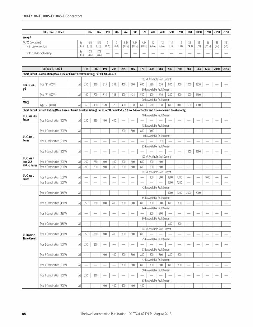
100-E/104-E, 100S-E/104S-E Contactors
WeightAC/DC (Electronic)
with bar connectionskg
(lbs.)1.50(3.3)
1.50(3.3)
3(6.6)
3(6.6)
4.64(10.2)
4.64(10.2)
4.64(10.2)
12(26.4)
12(26.4)
15(33)
15(33)
34(74.8)
35(77)
16(35.2)
35(77)
45(99)
with built-in cable clamps kg(lbs.)
1.75(3.85)
1.75(3.85) — — — — — — — — — — — — — —
100/104-E, 100S-E 116 146 190 205 265 305 370 400 460 580 750 860 1060 1260 2050 2650Short Circuit Coordination (Max. Fuse or Circuit Breaker Rating) Per IEC 60947-4-1
DIN Fuses - gG
100 kA Available Fault Current
Type "2" (400V) [A] 250 250 315 315 400 500 630 630 630 800 800 1000 1250 — — —
80 kA Available Fault Current
Type "2" (690V) [A] 160 200 315 315 400 425 500 500 630 800 800 1000 1600 — — —
MCCB70 kA Available Fault Current
Type "2" (400V) [A] 160 160 320 320 400 630 630 630 630 800 1000 1600 1600 — — —
Short Circuit Current Rating (Max. Fuse or Circuit Breaker Rating) Per UL 60947 and CSA 22.2 No. 14 (contactor and fuses or circuit breaker only)
UL Class RK5 Fuses
10 kA Available Fault Current
Type 1 Combination (600V) [A] 250 250 400 400 — — — — — — — — — — — —
UL Class L Fuses
18 kA Available Fault Current
Type 1 Combination (600V) [A] — — — — 800 800 800 1000 — — — — — — — —
30 kA Available Fault Current
Type 1 Combination (600V) [A] — — — — — — — — 1000 — — — — — — —
85 kA Available Fault Current
Type 1 Combination (600V) [A] — — — — — — — — — — — 1600 1600 — — —
UL Class J and CSA HRCI-J Fuses
100 kA Available Fault Current
Type 1 Combination (600V) [A] 250 250 400 400 600 600 600 600 600 — — — — — — —
Type 2 Combination (600V) [A] 200 200 400 400 600 600 600 600 600 — — — — — — —
UL Class L Fuses
100 kA Available Fault Current
Type 1 Combination (600V) [A] — — — — — — — 800 800 1200 1200 — — 1600 — —
Type 2 Combination (600V) [A] — — — — — — — — — 1200 1200 — — — — —
UL Inverse-Time Circuit
42 kA Available Fault Current
Type 1 Combination (480V) [A] — — — — — — — — — 1200 1200 2000 2000 — — —
65 kA Available Fault Current
Type 2 Combination (480V) [A] 250 250 400 400 800 800 800 800 800 800 800 — — — — —
84 kA Available Fault Current
Type 1 Combination (480V) [A] — — — — — — — 800 800 — — — — — — —
89 kA Available Fault Current
Type 1 Combination (480V) [A] — — — — — — — — — 800 800 — — — — —
100 kA Available Fault Current
Type 1 Combination (480V) [A] 250 250 400 400 800 800 800 — — — — — — — — —
25 kA Available Fault Current
Type 2 Combination (600V) [A] 250 250 — — — — — — — — — — — — — —
35 kA Available Fault Current
Type 2 Combination (600V) [A] — — 400 400 800 800 800 800 800 800 800 — — — — —
42 kA Available Fault Current
Type 1 Combination (600V) [A] — — — — 800 800 800 800 800 800 800 — — — — —
50 kA Available Fault Current
Type 1 Combination (600V) [A] 250 250 — — — — — — — — — — — — — —
65 kA Available Fault Current
Type 1 Combination (600V) [A] — — 400 400 400 400 400 — — — — — — — — —
100/104-E, 100S-E 116 146 190 205 265 305 370 400 460 580 750 860 1060 1260 2050 2650
88 Rockwell Automation Publication 100-TD013G-EN-P - August 2018
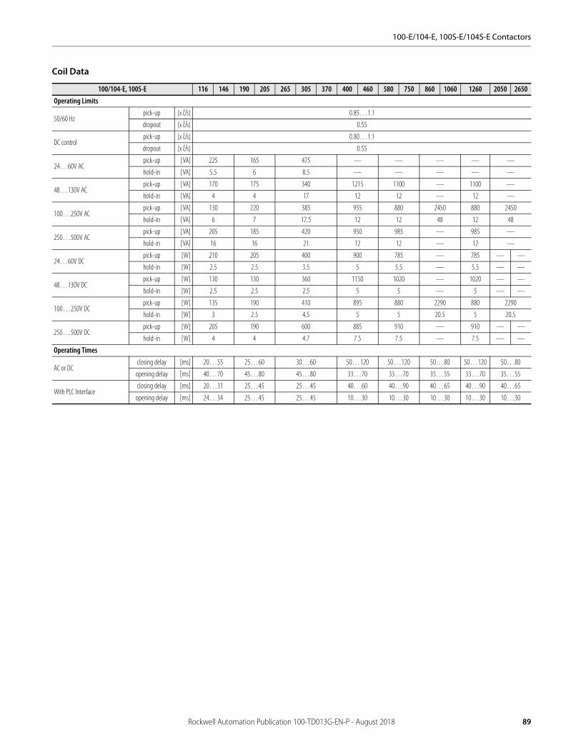
100-E/104-E, 100S-E/104S-E Contactors
Coil Data
100/104-E, 100S-E 116 146 190 205 265 305 370 400 460 580 750 860 1060 1260 2050 2650Operating Limits
50/60 Hzpick-up [x Us] 0.85…1.1
dropout [x Us] 0.55
DC control pick-up [x Us] 0.80…1.1
dropout [x Us] 0.55
24…60V ACpick-up [VA] 225 165 475 — — — — —
hold-in [VA] 5.5 6 8.5 — — — — —
48…130V ACpick-up [VA] 170 175 340 1215 1100 — 1100 —
hold-in [VA] 4 4 17 12 12 — 12 —
100…250V ACpick-up [VA] 130 220 385 955 880 2450 880 2450
hold-in [VA] 6 7 17.5 12 12 48 12 48
250…500V ACpick-up [VA] 205 185 420 950 985 — 985 —
hold-in [VA] 16 16 21 12 12 — 12 —
24…60V DCpick-up [W] 210 205 400 900 785 — 785 — —
hold-in [W] 2.5 2.5 3.5 5 5.5 — 5.5 — —
48…130V DCpick-up [W] 130 130 360 1150 1020 — 1020 — —
hold-in [W] 2.5 2.5 2.5 5 5 — 5 — —
100…250V DCpick-up [W] 135 190 410 895 880 2290 880 2290
hold-in [W] 3 2.5 4.5 5 5 20.5 5 20.5
250…500V DCpick-up [W] 205 190 600 885 910 — 910 — —
hold-in [W] 4 4 4.7 7.5 7.5 — 7.5 — —
Operating Times
AC or DCclosing delay [ms] 20…55 25…60 30…60 50…120 50…120 50…80 50…120 50…80
opening delay [ms] 40…70 45…80 45…80 33…70 33…70 35…55 33…70 35…55
With PLC Interfaceclosing delay [ms] 20…31 25…45 25…45 40…60 40…90 40…65 40…90 40…65
opening delay [ms] 24…34 25…45 25…45 10…30 10…30 10…30 10…30 10…30
Rockwell Automation Publication 100-TD013G-EN-P - August 2018 89
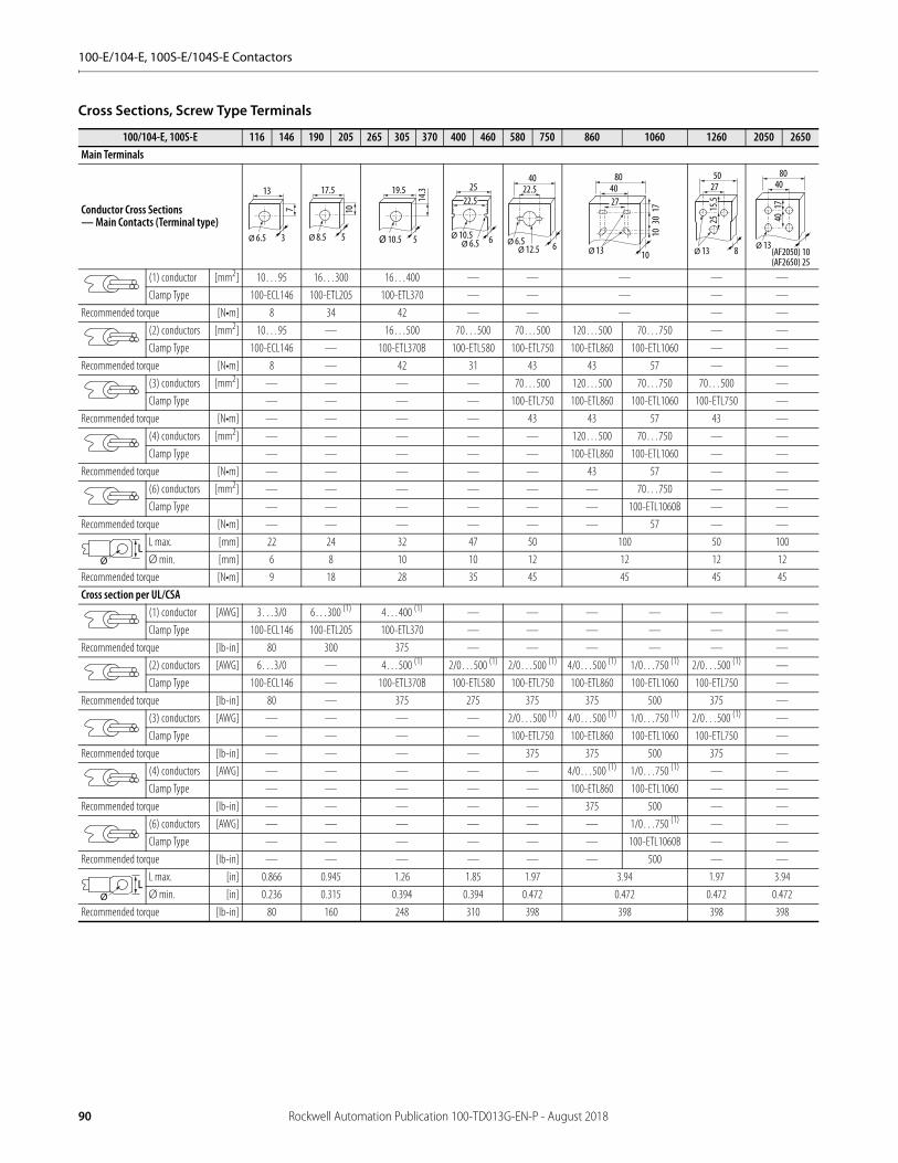
100-E/104-E, 100S-E/104S-E Contactors
Cross Sections, Screw Type Terminals
100/104-E, 100S-E 116 146 190 205 265 305 370 400 460 580 750 860 1060 1260 2050 2650Main Terminals
Conductor Cross Sections— Main Contacts (Terminal type)
(1) conductor [mm2] 10…95 16…300 16…400 — — — — —
Clamp Type 100-ECL146 100-ETL205 100-ETL370 — — — — —
Recommended torque [N•m] 8 34 42 — — — — —
(2) conductors [mm2] 10…95 — 16…500 70…500 70…500 120…500 70…750 — —
Clamp Type 100-ECL146 — 100-ETL370B 100-ETL580 100-ETL750 100-ETL860 100-ETL1060 — —
Recommended torque [N•m] 8 — 42 31 43 43 57 — —
(3) conductors [mm2] — — — — 70…500 120…500 70…750 70…500 —
Clamp Type — — — — 100-ETL750 100-ETL860 100-ETL1060 100-ETL750 —
Recommended torque [N•m] — — — — 43 43 57 43 —
(4) conductors [mm2] — — — — — 120…500 70…750 — —
Clamp Type — — — — — 100-ETL860 100-ETL1060 — —
Recommended torque [N•m] — — — — — 43 57 — —
(6) conductors [mm2] — — — — — — 70…750 — —
Clamp Type — — — — — — 100-ETL1060B — —
Recommended torque [N•m] — — — — — — 57 — —
L max. [mm] 22 24 32 47 50 100 50 100
Ø min. [mm] 6 8 10 10 12 12 12 12
Recommended torque [N•m] 9 18 28 35 45 45 45 45
Cross section per UL/CSA(1) conductor [AWG] 3…3/0 6…300 (1) 4…400 (1) — — — — — —
Clamp Type 100-ECL146 100-ETL205 100-ETL370 — — — — — —
Recommended torque [lb-in] 80 300 375 — — — — — —
(2) conductors [AWG] 6…3/0 — 4…500 (1) 2/0…500 (1) 2/0…500 (1) 4/0…500 (1) 1/0…750 (1) 2/0…500 (1) —
Clamp Type 100-ECL146 — 100-ETL370B 100-ETL580 100-ETL750 100-ETL860 100-ETL1060 100-ETL750 —
Recommended torque [lb-in] 80 — 375 275 375 375 500 375 —
(3) conductors [AWG] — — — — 2/0…500 (1) 4/0…500 (1) 1/0…750 (1) 2/0…500 (1) —
Clamp Type — — — — 100-ETL750 100-ETL860 100-ETL1060 100-ETL750 —
Recommended torque [lb-in] — — — — 375 375 500 375 —
(4) conductors [AWG] — — — — — 4/0…500 (1) 1/0…750 (1) — —
Clamp Type — — — — — 100-ETL860 100-ETL1060 — —
Recommended torque [lb-in] — — — — — 375 500 — —
(6) conductors [AWG] — — — — — — 1/0…750 (1) — —
Clamp Type — — — — — — 100-ETL1060B — —
Recommended torque [lb-in] — — — — — — 500 — —
L max. [in] 0.866 0.945 1.26 1.85 1.97 3.94 1.97 3.94
Ø min. [in] 0.236 0.315 0.394 0.394 0.472 0.472 0.472 0.472
Recommended torque [lb-in] 80 160 248 310 398 398 398 398
Ø 6.5
13
7
3 Ø 8.5
17.5
10
5 Ø 10.5
19.5
14.3
5 Ø 10.5
25
6Ø 6.5
22.5
Ø 6.5
22.540
6Ø 12.5
27
80
10
40
Ø 13
1030
17
2750
8Ø 13
2515
.5
80
(AF2050) 10(AF2650) 25
Ø 13
40
4017
LØ
LØ
90 Rockwell Automation Publication 100-TD013G-EN-P - August 2018
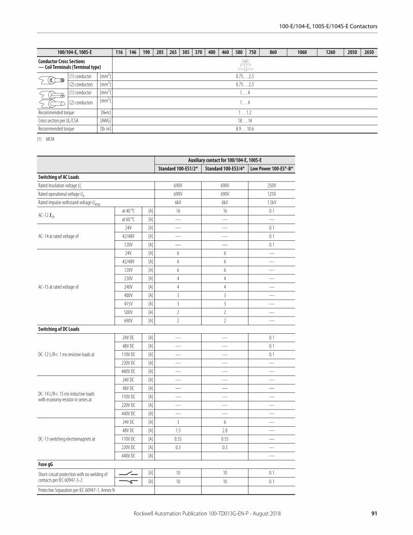
100-E/104-E, 100S-E/104S-E Contactors
Conductor Cross Sections— Coil Terminals (Terminal type)
(1) conductor [mm2] 0.75…2.5
(2) conductors [mm2] 0.75…2.5
(1) conductor [mm2] 1…4
(2) conductors [mm2] 1…4
Recommended torque [N•m] 1…1.2
Cross section per UL/CSA [AWG] 18…14
Recommended torque [lb-in] 8.9…10.6
(1) MCM
Auxiliary contact for 100/104-E, 100S-EStandard 100-ES1/2* Standard 100-ES3/4* Low Power 100-ES*-B*
Switching of AC LoadsRated Insulation voltage Ui 690V 690V 250V
Rated operational voltage Ue 690V 690V 125V
Rated impulse withstand voltage Uimp 6kV 6kV 1.5kV
AC-12 Ithat 40 °C [A] 16 16 0.1
at 60 °C [A] — — —
AC-14 at rated voltage of
24V [A] — — 0.1
42/48V [A] — — 0.1
120V [A] — — 0.1
AC-15 at rated voltage of
24V [A] 6 6 —
42/48V [A] 6 6 —
120V [A] 6 6 —
230V [A] 4 4 —
240V [A] 4 4 —
400V [A] 3 3 —
415V [A] 3 3 —
500V [A] 2 2 —
690V [A] 2 2 —
Switching of DC Loads
DC-12 L/R< 1 ms resistive loads at
24V DC [A] — — 0.1
48V DC [A] — — 0.1
110V DC [A] — — 0.1
220V DC [A] — — —
440V DC [A] — — —
DC-14 L/R< 15 ms inductive loadswith economy resistor in series at
24V DC [A] — — —
48V DC [A] — — —
110V DC [A] — — —
220V DC [A] — — —
440V DC [A] — — —
DC-13 switching electromagnets at
24V DC [A] 3 6 —
48V DC [A] 1.5 2.8 —
110V DC [A] 0.55 0.55 —
220V DC [A] 0.3 0.3 —
440V DC [A] —
Fuse gG
Short-circuit protection with no welding of contacts per IEC 60947-5-2
[A] 10 10 0.1
[A] 10 10 0.1
Protective Separation per IEC 60947-1, Annex N
100/104-E, 100S-E 116 146 190 205 265 305 370 400 460 580 750 860 1060 1260 2050 2650
Rockwell Automation Publication 100-TD013G-EN-P - August 2018 91
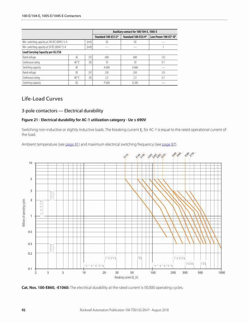
100-E/104-E, 100S-E/104S-E Contactors
Life-Load Curves
3-pole contactors — Electrical durability
Figure 21 - Electrical durability for AC-1 utilization category - Ue ≤ 690V
Switching non-inductive or slightly inductive loads. The breaking current Ic for AC-1 is equal to the rated operational current of the load.
Ambient temperature (see page 81) and maximum electrical switching frequency (see page 87).
Cat. Nos. 100-E860, -E1060: The electrical durability at the rated current is 50,000 operating cycles.
Min. switching capacity at 24V IEC 60947-5-4 [mA] 50 50 —
Min. switching capacity at 3V IEC 60947-5-4 [mA] — — 1
Load Carrying Capacity per UL/CSARated voltage AC [V] 600 600 125
Continuous rating 40 °C [A] 10 10 0.1
Switching capacity AC A 600 A 600 —
Rated voltage DC [V] 250 250 125
Continuous rating 40 °C [A] 2.5 2.5 0.1
Switching capacity DC P 600 Q 300 —
Auxiliary contact for 100/104-E, 100S-EStandard 100-ES1/2* Standard 100-ES3/4* Low Power 100-ES*-B*
1 3 5 7 9
1 3 5 7 9 1 5 9
1
3
5
79
13579
1 3 5 7 9
1 3 5 7 9
1 3 5 7 9 1 5 9
13579
10
1
0.1
0.2
0.3
0.5
3
5
10 100 10002 3 5 20 30 50 200 300 500
E400E460
E580E750
2
E116E146
E190E205
E265E305
E370
Milli
ons o
f ope
rating
cycle
s
Breaking current Ic [A]
92 Rockwell Automation Publication 100-TD013G-EN-P - August 2018

100-E/104-E, 100S-E/104S-E Contactors
Figure 22 - Electrical durability for AC-3 utilization category - Ue ≤ 440V
Switching cage motors: starting and switching off running motors. The breaking current Ic for AC-3 is equal to the rated operational current Ie (Ie = motor full load current).
For ambient temperature (see page 81) and maximum electrical switching frequency (see page 87).
Cat. Nos. 100-E860, -E1060: The electrical durability at the rated current is 50,000 operating cycles.
Milli
ons o
f ope
rating
cycle
s
Breaking current Ic [A]
10
1
10 100 10002 3 5 20 30 50 200 300 5000.2
0.3
0.5
2
3
5
1 3 5 7 9
1 3 5 7 9
13579
1
3
5
79
1 3 5 7 9 1 3 5 7 9
1 5 9
1 5 9
1 3 5 7 9 1 3 5 7 9
E400E460
E580E750
E116190
E205E305
E370E265
E146
Rockwell Automation Publication 100-TD013G-EN-P - August 2018 93
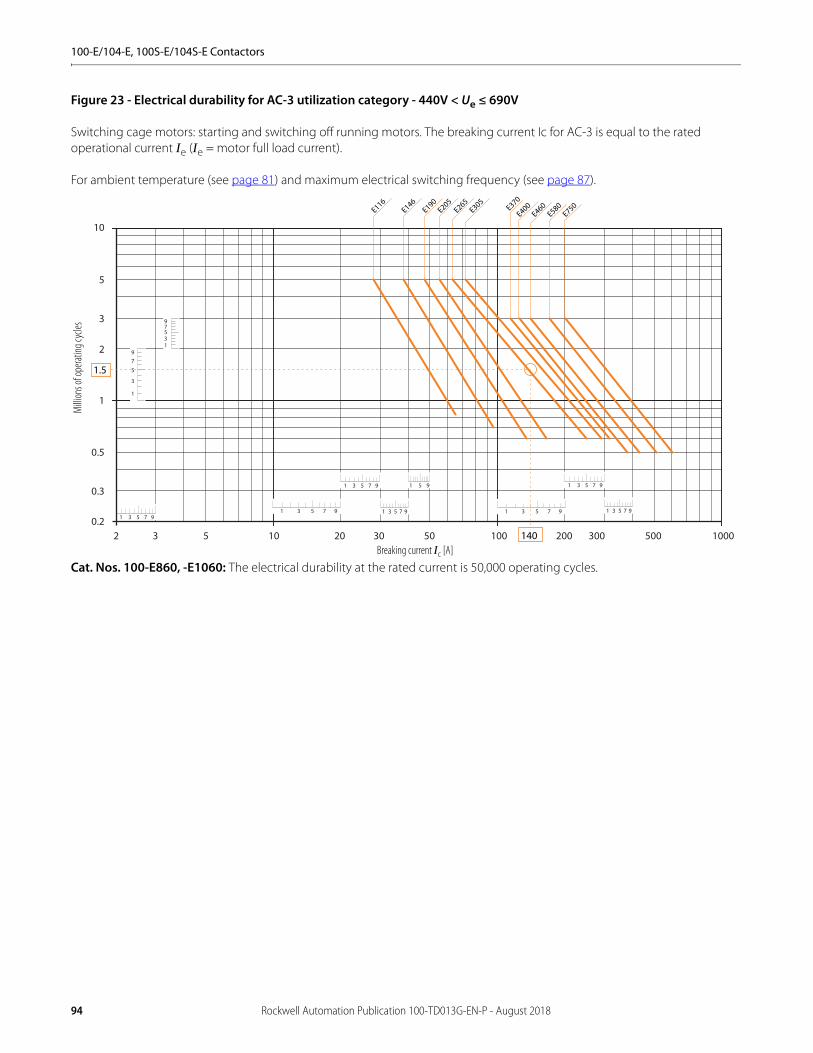
100-E/104-E, 100S-E/104S-E Contactors
Figure 23 - Electrical durability for AC-3 utilization category - 440V < Ue ≤ 690V
Switching cage motors: starting and switching off running motors. The breaking current Ic for AC-3 is equal to the rated operational current Ie (Ie = motor full load current).
For ambient temperature (see page 81) and maximum electrical switching frequency (see page 87).
Cat. Nos. 100-E860, -E1060: The electrical durability at the rated current is 50,000 operating cycles.
Milli
ons o
f ope
rating
cycle
s
Breaking current Ic [A]
1 3 5 7 9
1 3 5 7 9
1 5 9
13579
1
3
5
79
1 3 5 7 9 1 3 5 7 9
1 3 5 7 9
1 3 5 7 91 3 5 7 9
10
1
10 100 10002 3 5 20 30 50 200 300 5000.2
0.3
0.5
2
3
5
E116E146
E190E205
E265E305
E370
E400E460
E580E750
1.5
140
94 Rockwell Automation Publication 100-TD013G-EN-P - August 2018

100-E/104-E, 100S-E/104S-E Contactors
Figure 24 - Electrical durability for AC-2 or AC-4 utilization category - Ue ≤ 440V
Switching cage motors: starting, reverse operation and step-by-step operation. The breaking current Ic is equal to 2.5 x Ie for AC-2 and 6 x Ie for AC-4,
keeping in mind that Ie is the motor rated operational current (Ie = motor full-load current). For maximum electrical switching frequency (see page 87).
Milli
ons o
f ope
rating
cycle
s
Breaking current Ic [A]30001000100102 3 5 20 30 50 200 300 500 2000 5000
10
1
0.1
0.005
0.01
0.02
0.03
0.05
0.3
0.2
0.5
2
3
5
1 3 5 7 9
1 3 5 7 9
1 3 5 7 9
1 3 5 7 9 1 3 5 7 9
13579
13579
13579
E400E460
E580E750
E116, E146
E205 E265E190
E305
E370
Rockwell Automation Publication 100-TD013G-EN-P - August 2018 95
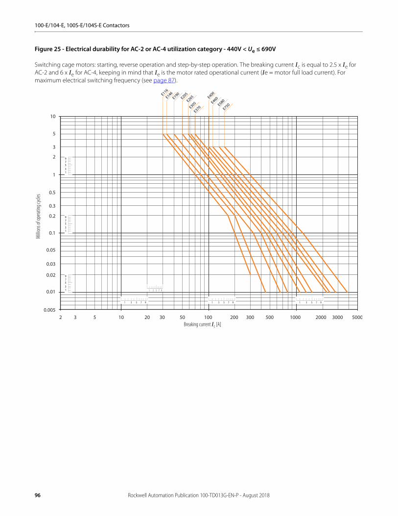
100-E/104-E, 100S-E/104S-E Contactors
Figure 25 - Electrical durability for AC-2 or AC-4 utilization category - 440V < Ue ≤ 690V
Switching cage motors: starting, reverse operation and step-by-step operation. The breaking current Ic is equal to 2.5 x Ie for AC-2 and 6 x Ie for AC-4, keeping in mind that Ie is the motor rated operational current (Ie = motor full load current). For maximum electrical switching frequency (see page 87).
Milli
ons o
f ope
rating
cycle
s
Breaking current Ic [A]
E116
E190E146
E205
E265
E305
E370
1 3 5 7 9 1 3 5 7 9
10
1
0.1
0.005
0.01
0.02
0.03
0.05
0.2
0.3
0.5
2
3
5
50001000100102 3 5 20 30 50 200 300 500 2000 3000
13579
13579
13579
1 3 5 7 9
1 3 5 7 9
E400
E460
E580
E750
96 Rockwell Automation Publication 100-TD013G-EN-P - August 2018
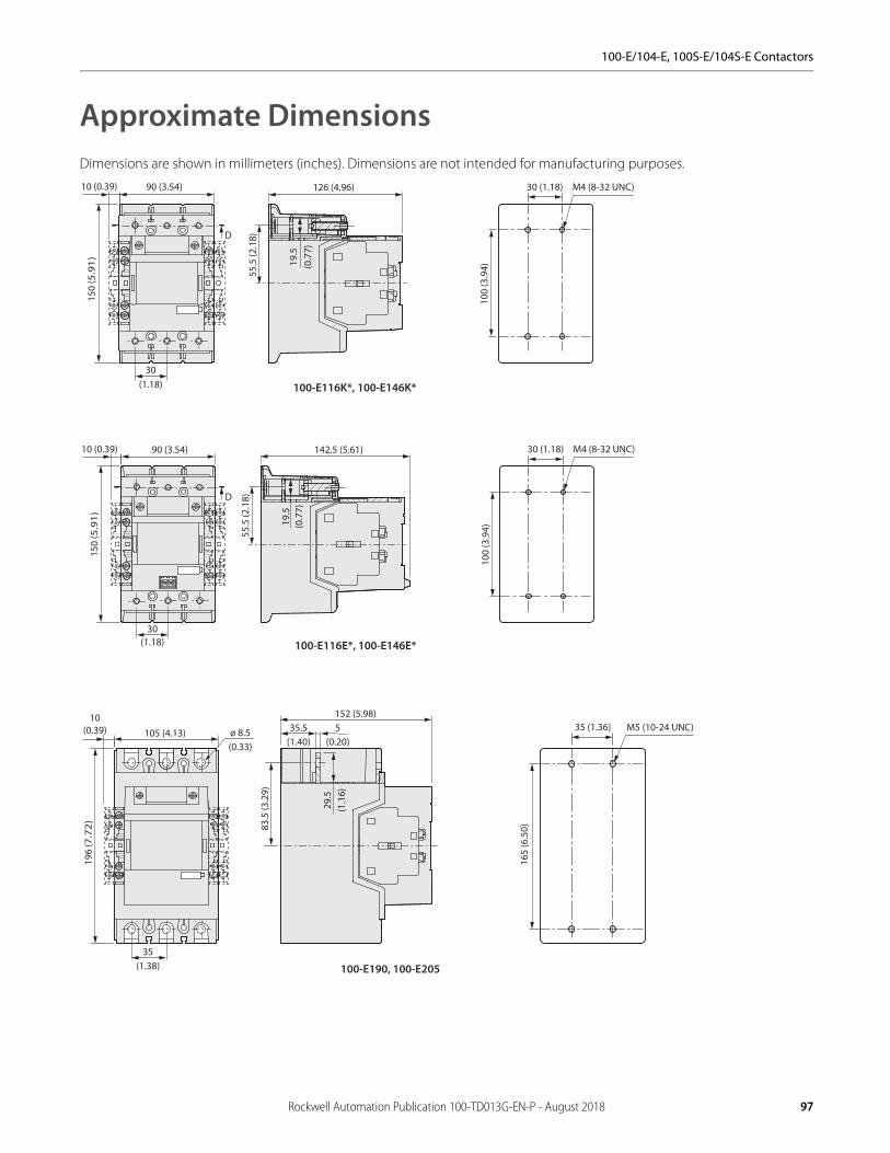
100-E/104-E, 100S-E/104S-E Contactors
Approximate DimensionsDimensions are shown in millimeters (inches). Dimensions are not intended for manufacturing purposes.
55.5
(2.1
8)
150
(5.9
1)
90 (3.54) 126 (4.96)
D
10 (0.39)
30(1.18)
19.5
(0.7
7)
30 (1.18) M4 (8-32 UNC)
100
(3.9
4)
100-E116K*, 100-E146K*
90 (3.54)
30(1.18)
D
150
(5.9
1)
10 (0.39)
55.5
(2.1
8)
19.5
(0.7
7)
142.5 (5.61) 30 (1.18) M4 (8-32 UNC)
100
(3.9
4)
100-E116E*, 100-E146E*
105 (4.13) ø 8.5(0.33)
35(1.38)
196
(7.7
2)
10(0.39)
152 (5.98)
83.5
(3.2
9)
35.5(1.40)
5(0.20)
29.5
(1.1
6)
35 (1.36) M5 (10-24 UNC)
165
(6.5
0)
100-E190, 100-E205
Rockwell Automation Publication 100-TD013G-EN-P - August 2018 97
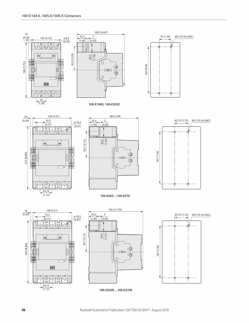
100-E/104-E, 100S-E/104S-E Contactors
105 (4.13) ø 8.5(0.33)
35(1.38)
196
(7.7
2)
10(0.39)
83.5
(3.2
9)
35.5(1.40)
5(0.20)
29.5
(1.1
6)
169.5 (6.67)35 (1.36) M5 (10-24 UNC)
165
(6.5
0)
100-E190E, 100-E205E
140 (5.51)
19.5(0.77)
ø 10.5(0.41)
43.75(1.72)
180 (7.09)
94.7
(3.7
3)
225
(8.8
6)
35.5(1.40)
5(0.20)
33.4
(1.3
1)
10(0.39) 43.75 (1.72) M5 (10-24 UNC)
187
(7.3
6)
100-E265…100-E370
140 (5.51)
19.5(0.77)
ø 10.5(0.41)
43.75(1.72)
94.7
(3.7
3)
225
(8.8
6)
35.5(1.40)
5(0.20)
33.4
(1.3
1)
10(0.39)
195.5 (7.70)
43.75 (1.72) M5 (10-24 UNC)
187
(7.3
6)
100-E265E…100-E370E
98 Rockwell Automation Publication 100-TD013G-EN-P - August 2018

100-E/104-E, 100S-E/104S-E Contactors
63 (2.48)
186 (7.32)
25(0.98) 22.5 (0.89)
11.5
(0.4
5)
268
(10.
55)
ø 10.5(0.41)
216 (8.5)48.5
(1.91)6
(0.24)
278
(10.
94)
ø 6.5(0.26)
63 (2.48)
248
(9.7
6)
M5 (10-24 UNC)
100-E400, 100-E460
72 (2.83)
210 (8.27)
40(1.57)
22.5 (0.89)
11.5
(0.4
5)
273
(10.
75)
ø 12.5(0.49)
ø 6.5(0.26)
242 (9.53)48.5
(1.91)6
(0.24)
283
(11.
14)
100-E580…100-E750
72 (2.83)
249
(9.8
)
M6 (1/4-20 UNC)
50 (1.97)
72 (2.83)
72 (2.83)
210 (8.27)
344
(13.
54)
313
(12.
32)
263
(10.
35)
72 (2.83)
ø 7(0.28)
ø 7(0.28)
27
249
(9.8
)
242 (9.53)
46.5(18.3)
8 (0.31)
100-E1260
72 (2.83)
249
(9.8
)
M6 (1/4-20 UNC)
Rockwell Automation Publication 100-TD013G-EN-P - August 2018 99
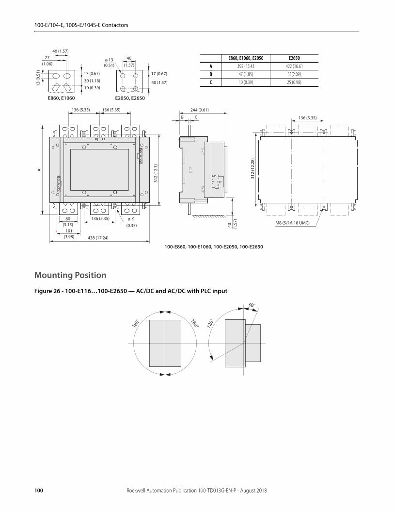
100-E/104-E, 100S-E/104S-E Contactors
Mounting Position
Figure 26 - 100-E116…100-E2650 — AC/DC and AC/DC with PLC input
40
(1.5
7)
E2050, E2650
40
(1.57)ø 13
(0.51)
136 (5.35) 136 (5.35)
80(3.15)
ø 9 (0.35)
B
438 (17.24)
A
312
(12.
3)
C
244 (9.61)
101(3.98)
40 (1.57)27
(1.06)
30 (1.18)
17 (0.67)
40 (1.57)
17 (0.67)
10 (0.39)
E860, E1060
13 (0
.51)
136 (5.35)
100-E860, 100-E1060, 100-E2050, 100-E2650
136 (5.35)
M8 (5/16-18 UMC)
312
(12.
28)
E860, E1060, E2050 E2650A 392 (15.43 422 (16.61
B 47 (1.85) 53(2.09)
C 10 (0.39) 25 (0.98)
30°
120°
180°
180°
100 Rockwell Automation Publication 100-TD013G-EN-P - August 2018
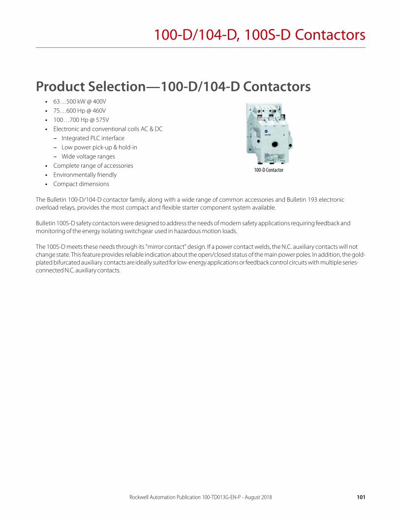
100-D/104-D, 100S-D Contactors
Product Selection—100-D/104-D Contactors• 63…500 kW @ 400V• 75…600 Hp @ 460V• 100…700 Hp @ 575V• Electronic and conventional coils AC & DC
– Integrated PLC interface– Low power pick-up & hold-in – Wide voltage ranges
• Complete range of accessories • Environmentally friendly • Compact dimensions
The Bulletin 100-D/104-D contactor family, along with a wide range of common accessories and Bulletin 193 electronic overload relays, provides the most compact and flexible starter component system available.
Bulletin 100S-D safety contactors were designed to address the needs of modern safety applications requiring feedback and monitoring of the energy isolating switchgear used in hazardous motion loads.
The 100S-D meets these needs through its "mirror contact" design. If a power contact welds, the N.C. auxiliary contacts will not change state. This feature provides reliable indication about the open/closed status of the main power poles. In addition, the gold-plated bifurcated auxiliary contacts are ideally suited for low-energy applications or feedback control circuits with multiple series-connected N.C. auxiliary contacts.
100-D Contactor
Rockwell Automation Publication 100-TD013G-EN-P - August 2018 101
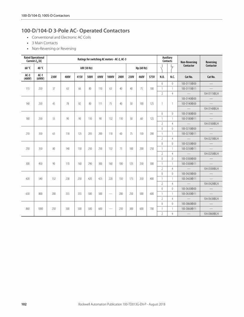
100-D/104-D, 100S-D Contactors
100-D/104-D 3-Pole AC- Operated Contactors• Conventional and Electronic AC Coils • 3 Main Contacts• Non-Reversing or Reversing
Rated Operational Current Ie [A] Ratings for switching AC motors - AC-2, AC-3 Auxiliary
Contacts Non-ReversingContactor
ReversingContactor
60 °C 40 °C kW (50 Hz) Hp (60 Hz)
AC-3 (400V)
AC-1 (690V) 230V 400V 415V 500V 690V 1000V 200V 230V 460V 575V N.O. N.C. Cat No. Cat No.
115 250 37 63 66 80 110 63 40 40 75 100
0 0 100-D11500 —
1 1 100-D11511 —
2 4 — 104-D11524
140 250 45 78 82 80 111 75 40 50 100 125 1 1
100-D14000 —
100-D14000 —
— 104-D14024
180 250 55 90 90 110 90 132 110 50 60 125
0 0 100-D18000 —
1 1 100-D18011 —
2 4 — 104-D18024
210 350 63 118 125 205 200 110 60 75 150 200
0 0 100-D21000 —
1 1 100-D21011 —
2 4 — 104-D21024
250 350 80 140 150 250 250 132 75 100 200 250
0 0 100-D25000 —
1 1 100-D25011 —
2 4 — 104-D25024
300 450 90 170 160 290 300 160 100 125 250 300
0 0 100-D30000 —
1 1 100-D30011 —
2 4 — 104-D30024
420 540 132 238 250 420 425 220 150 175 350 400
0 0 100-D42000 —
1 1 100-D42011 —
2 4 — 104-D42024
630 800 200 355 355 500 500 — 200 250 500 600
0 0 100-D63000 —
1 1 100-D63011 —
2 4 — 104-D63024
860 1000 250 500 500 500 600 — 250 300 600 700
0 0 100-D86000 —
1 1 100-D86011 —
2 4 — 104-D86024
102 Rockwell Automation Publication 100-TD013G-EN-P - August 2018

100-D/104-D, 100S-D Contactors
3-Pole DC-operated Contactors• Conventional and Electronic DC Coils • 3 Main Contacts• Non-Reversing or Reversing
Rated Operational
Current Ie [A]Ratings for switching AC motors - AC-2, AC-3 Auxiliary
Contacts Non-ReversingContactor
ReversingContactor
60 °C 40 °C kW (50 Hz) Hp (60 Hz)
AC-3 (400V)
AC-1 (690V) 230V 400V 415V 500V 690V 1000V 200V 230V 460V 575V N.O. N.C. Cat No. Cat No.
115 250 37 63 66 80 110 63 40 40 75 100
0 0 100-D11500 —
1 1 100-D11511 —
2 1/1L 100-D11522L —
2 4 — 104-D11524
2 2/2L — 104-D11522L
140 250 45 78 82 80 111 75 40 50 100 125
0 0 100-D14000 —
1 1 100-D14000 —
2 1/1L 100-D14022L —
2 4 — 104-D14024
2 2/2L — 104-D14022L
180 250 55 90 90 110 90 132 110 50 60 125
0 0 100-D18000 —
1 1 100-D18000 —
2 1/1L 100-D18022L —
2 4 — 104-D18024
2 2/2L — 104-D18022L
210 350 63 118 125 205 200 110 60 75 150 200
0 0 100-D21000 —
1 1 100-D21011 —
2 4 — 104-D21024
250 350 80 140 150 250 250 132 75 100 200 250
0 0 100-D25000 —
1 1 100-D25011 —
2 4 — 104-D25024
300 450 90 170 160 290 300 160 100 125 250 300
0 0 100-D30000 —
1 1 100-D30011 —
2 4 — 104-D30024
420 540 132 238 250 420 425 220 150 175 350 400
0 0 100-D42000 —
1 1 100-D42011 —
2 4 — 104-D42024
630 800 200 355 355 500 500 — 200 250 500 600
0 0 100-D63000 —
1 1 100-D63011 —
2 4 — 104-D63024
860 1000 250 500 500 500 600 — 250 300 600 700
0 0 100-D86000 —
1 1 100-D86011 —
2 4 — 104-D86024
Rockwell Automation Publication 100-TD013G-EN-P - August 2018 103
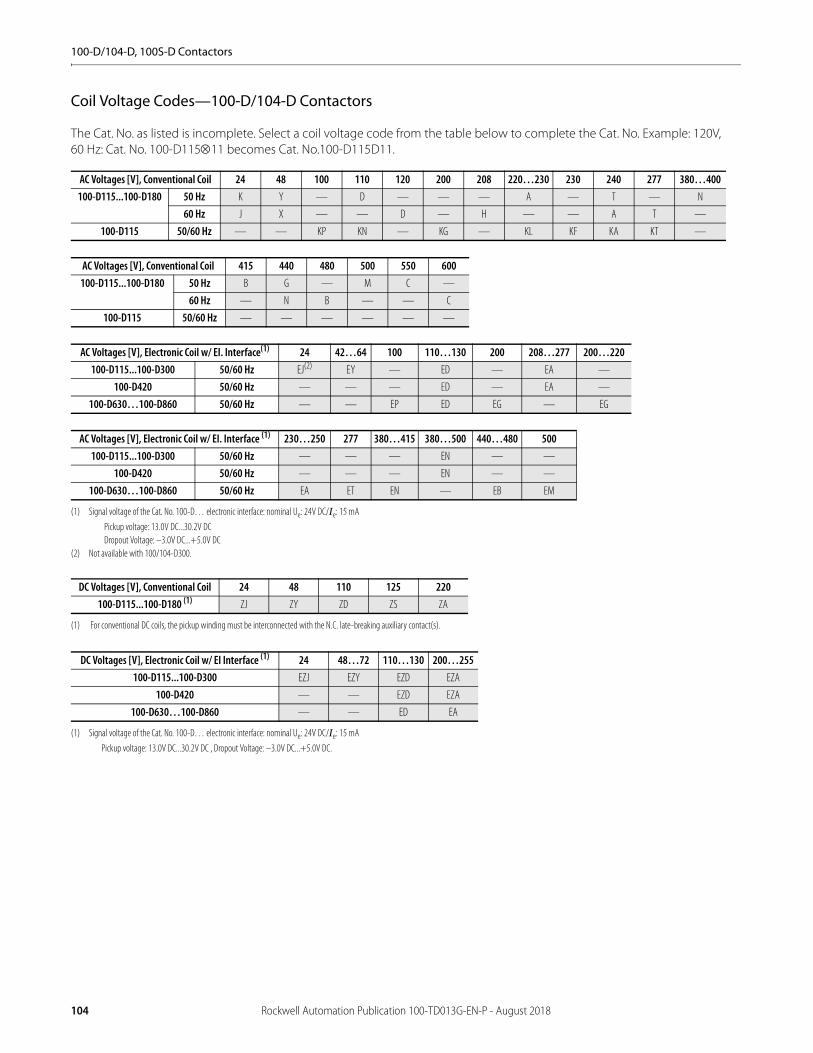
100-D/104-D, 100S-D Contactors
Coil Voltage Codes—100-D/104-D Contactors
The Cat. No. as listed is incomplete. Select a coil voltage code from the table below to complete the Cat. No. Example: 120V, 60 Hz: Cat. No. 100-D11511 becomes Cat. No.100-D115D11.
AC Voltages [V], Conventional Coil 24 48 100 110 120 200 208 220…230 230 240 277 380…400100-D115...100-D180 50 Hz K Y — D — — — A — T — N
60 Hz J X — — D — H — — A T —
100-D115 50/60 Hz — — KP KN — KG — KL KF KA KT —
AC Voltages [V], Conventional Coil 415 440 480 500 550 600100-D115...100-D180 50 Hz B G — M C —
60 Hz — N B — — C
100-D115 50/60 Hz — — — — — —
AC Voltages [V], Electronic Coil w/ EI. Interface(1)
(1) Signal voltage of the Cat. No. 100-D… electronic interface: nominal Ue: 24V DC/Ie: 15 mA
Pickup voltage: 13.0V DC...30.2V DCDropout Voltage: –3.0V DC...+5.0V DC
24 42…64 100 110…130 200 208…277 200…220100-D115...100-D300 50/60 Hz EJ(2)
(2) Not available with 100/104-D300.
EY — ED — EA —
100-D420 50/60 Hz — — — ED — EA —
100-D630…100-D860 50/60 Hz — — EP ED EG — EG
AC Voltages [V], Electronic Coil w/ EI. Interface (1) 230…250 277 380…415 380…500 440…480 500100-D115...100-D300 50/60 Hz — — — EN — —
100-D420 50/60 Hz — — — EN — —
100-D630…100-D860 50/60 Hz EA ET EN — EB EM
DC Voltages [V], Conventional Coil 24 48 110 125 220100-D115...100-D180 (1)
(1) For conventional DC coils, the pickup winding must be interconnected with the N.C. late-breaking auxiliary contact(s).
ZJ ZY ZD ZS ZA
DC Voltages [V], Electronic Coil w/ EI Interface (1)
(1) Signal voltage of the Cat. No. 100-D… electronic interface: nominal Ue: 24V DC/Ie: 15 mA
Pickup voltage: 13.0V DC...30.2V DC , Dropout Voltage: –3.0V DC...+5.0V DC.
24 48…72 110…130 200…255100-D115...100-D300 EZJ EZY EZD EZA
100-D420 — — EZD EZA
100-D630…100-D860 — — ED EA
104 Rockwell Automation Publication 100-TD013G-EN-P - August 2018
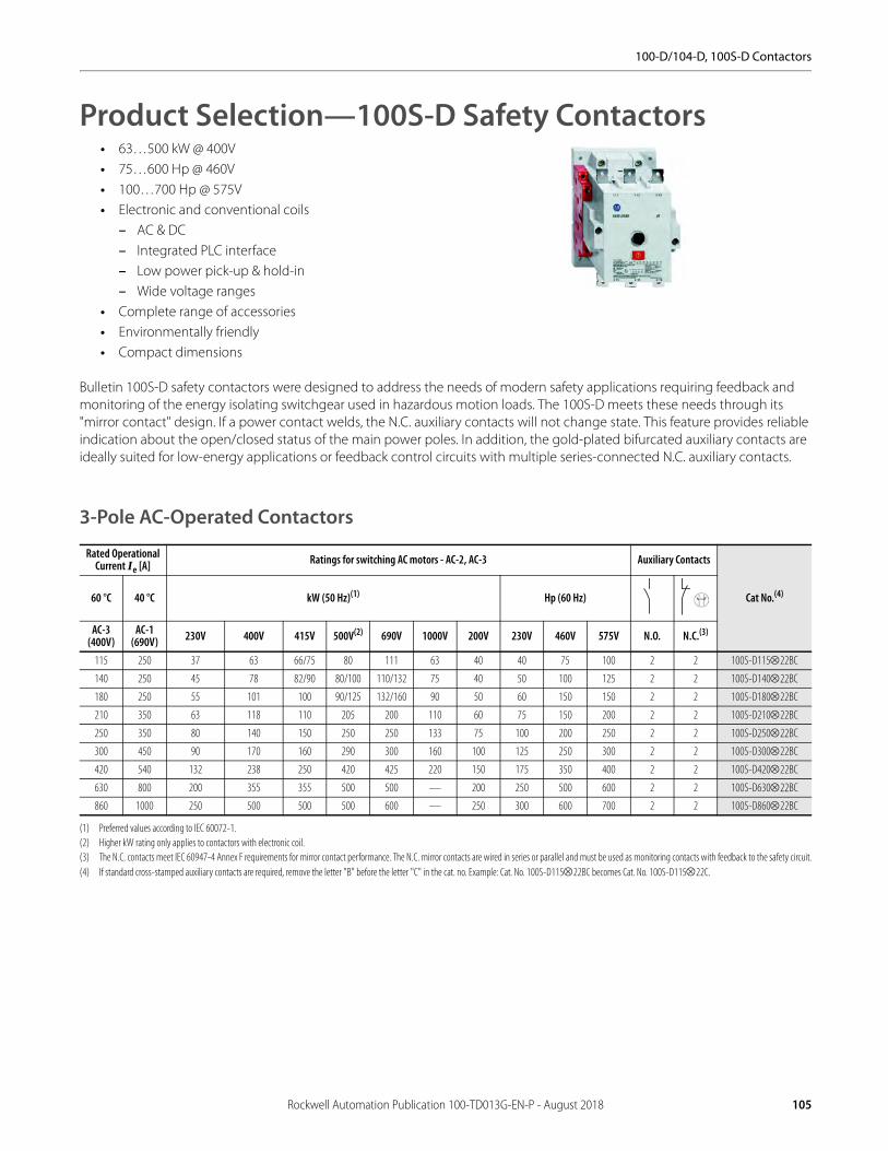
100-D/104-D, 100S-D Contactors
Product Selection—100S-D Safety Contactors• 63…500 kW @ 400V• 75…600 Hp @ 460V• 100…700 Hp @ 575V• Electronic and conventional coils
– AC & DC– Integrated PLC interface– Low power pick-up & hold-in– Wide voltage ranges
• Complete range of accessories• Environmentally friendly• Compact dimensions
Bulletin 100S-D safety contactors were designed to address the needs of modern safety applications requiring feedback and monitoring of the energy isolating switchgear used in hazardous motion loads. The 100S-D meets these needs through its "mirror contact" design. If a power contact welds, the N.C. auxiliary contacts will not change state. This feature provides reliable indication about the open/closed status of the main power poles. In addition, the gold-plated bifurcated auxiliary contacts are ideally suited for low-energy applications or feedback control circuits with multiple series-connected N.C. auxiliary contacts.
3-Pole AC-Operated Contactors
Rated Operational Current Ie [A] Ratings for switching AC motors - AC-2, AC-3 Auxiliary Contacts
Cat No.(4)
(4) If standard cross-stamped auxiliary contacts are required, remove the letter "B" before the letter "C" in the cat. no. Example: Cat. No. 100S-D11522BC becomes Cat. No. 100S-D11522C.
60 °C 40 °C kW (50 Hz)(1)
(1) Preferred values according to IEC 60072-1.
Hp (60 Hz)
AC-3 (400V)
AC-1 (690V) 230V 400V 415V 500V(2)
(2) Higher kW rating only applies to contactors with electronic coil.
690V 1000V 200V 230V 460V 575V N.O. N.C.(3)
(3) The N.C. contacts meet IEC 60947-4 Annex F requirements for mirror contact performance. The N.C. mirror contacts are wired in series or parallel and must be used as monitoring contacts with feedback to the safety circuit.
115 250 37 63 66/75 80 111 63 40 40 75 100 2 2 100S-D11522BC
140 250 45 78 82/90 80/100 110/132 75 40 50 100 125 2 2 100S-D14022BC
180 250 55 101 100 90/125 132/160 90 50 60 150 150 2 2 100S-D18022BC
210 350 63 118 110 205 200 110 60 75 150 200 2 2 100S-D21022BC
250 350 80 140 150 250 250 133 75 100 200 250 2 2 100S-D25022BC
300 450 90 170 160 290 300 160 100 125 250 300 2 2 100S-D30022BC
420 540 132 238 250 420 425 220 150 175 350 400 2 2 100S-D42022BC
630 800 200 355 355 500 500 — 200 250 500 600 2 2 100S-D63022BC
860 1000 250 500 500 500 600 — 250 300 600 700 2 2 100S-D86022BC
Rockwell Automation Publication 100-TD013G-EN-P - August 2018 105
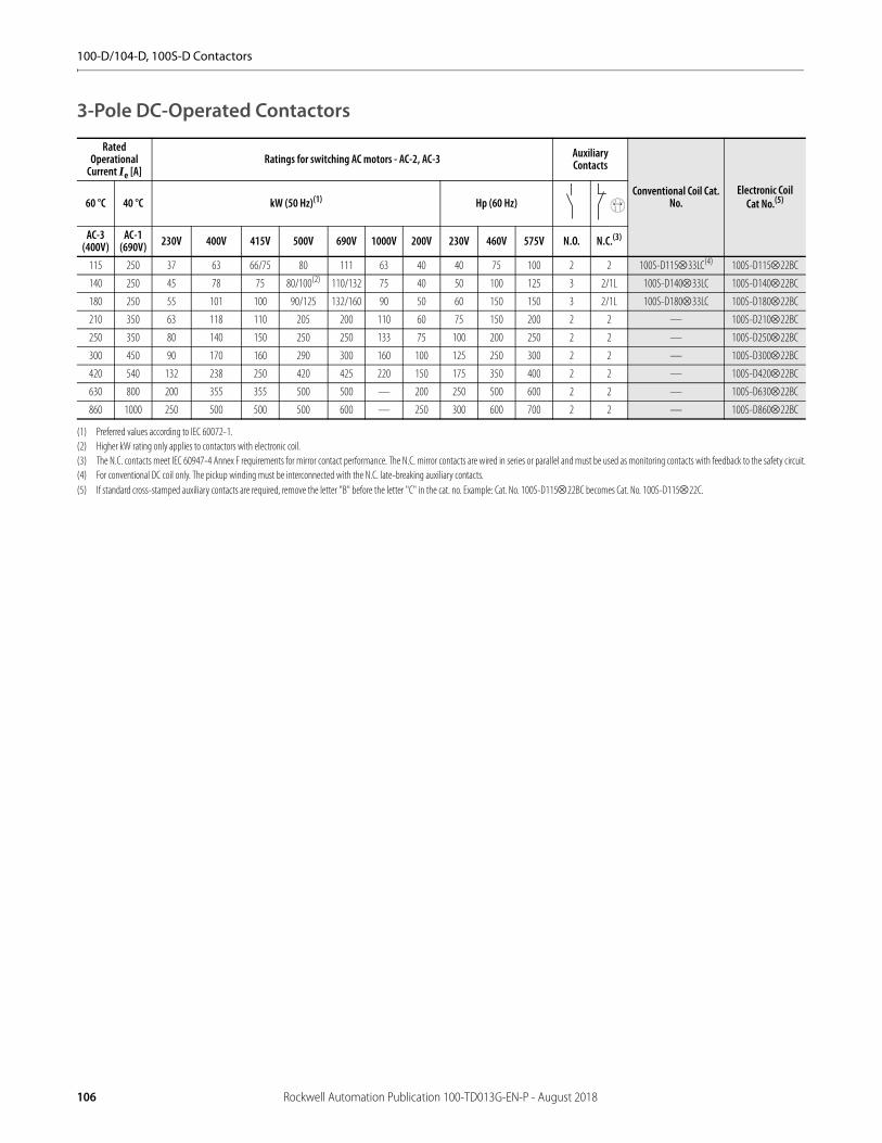
100-D/104-D, 100S-D Contactors
3-Pole DC-Operated Contactors
Rated Operational
Current Ie [A]Ratings for switching AC motors - AC-2, AC-3 Auxiliary
Contacts
Conventional Coil Cat. No.
Electronic Coil Cat No.(5)
(5) If standard cross-stamped auxiliary contacts are required, remove the letter "B" before the letter "C" in the cat. no. Example: Cat. No. 100S-D11522BC becomes Cat. No. 100S-D11522C.
60 °C 40 °C kW (50 Hz)(1)
(1) Preferred values according to IEC 60072-1.
Hp (60 Hz)
AC-3 (400V)
AC-1 (690V) 230V 400V 415V 500V 690V 1000V 200V 230V 460V 575V N.O. N.C.(3)
(3) The N.C. contacts meet IEC 60947-4 Annex F requirements for mirror contact performance. The N.C. mirror contacts are wired in series or parallel and must be used as monitoring contacts with feedback to the safety circuit.
115 250 37 63 66/75 80 111 63 40 40 75 100 2 2 100S-D11533LC(4)
(4) For conventional DC coil only. The pickup winding must be interconnected with the N.C. late-breaking auxiliary contacts.
100S-D11522BC
140 250 45 78 75 80/100(2)
(2) Higher kW rating only applies to contactors with electronic coil.
110/132 75 40 50 100 125 3 2/1L 100S-D14033LC 100S-D14022BC
180 250 55 101 100 90/125 132/160 90 50 60 150 150 3 2/1L 100S-D18033LC 100S-D18022BC
210 350 63 118 110 205 200 110 60 75 150 200 2 2 — 100S-D21022BC
250 350 80 140 150 250 250 133 75 100 200 250 2 2 — 100S-D25022BC
300 450 90 170 160 290 300 160 100 125 250 300 2 2 — 100S-D30022BC
420 540 132 238 250 420 425 220 150 175 350 400 2 2 — 100S-D42022BC
630 800 200 355 355 500 500 — 200 250 500 600 2 2 — 100S-D63022BC
860 1000 250 500 500 500 600 — 250 300 600 700 2 2 — 100S-D86022BC
106 Rockwell Automation Publication 100-TD013G-EN-P - August 2018
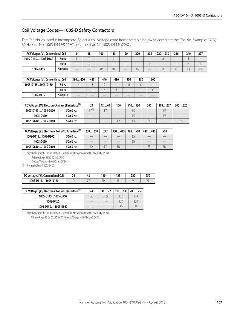
100-D/104-D, 100S-D Contactors
Coil Voltage Codes—100S-D Safety Contactors
The Cat. No. as listed is incomplete. Select a coil voltage code from the table below to complete the Cat. No. Example: 120V, 60 Hz: Cat. No. 100S-D11522BC becomes Cat. No.100S-D115D22BC.
AC Voltages [V], Conventional Coil 24 48 100 110 120 200 208 220…230 230 240 277100S-D115…100S-D180 50 Hz K Y — D — — — A — T —
60 Hz J X — — D — H — — A T
100S-D115 50/60 Hz — — KP KN — KG — KL KF KA KT
AC Voltages [V], Conventional Coil 380…400 415 440 480 500 550 600100S-D115...100S-D180 50 Hz N B G — M C —
60 Hz — — N B — — C
100S-D115 50/60 Hz — — — — — — —
AC Voltages [V], Electronic Coil w/ EI Interface(1)
(1) Signal voltage of the Cat. No. 100S-D… electronic interface: nominal Ue: 24V DC/Ie: 15 mA
Pickup voltage: 13.0V DC...30.2V DCDropout Voltage: –3.0V DC...+5.0V DC
24 42…64 100 110…130 200 208…277 200…220100S-D115…100S-D300 50/60 Hz EJ(2)
(2) Not available with 100S-D300
EY — ED — EA —
100S-D420 50/60 Hz — — — ED — EA —
100S-D630…100S-D860 50/60 Hz — — EP ED EG — EG
AC Voltages [V], Electronic Coil w/ EI Interface (1) 230…250 277 380…415 380…500 440…480 500100S-D115...100S-D300 50/60 Hz — — — EN — —
100S-D420 50/60 Hz — — — EN — —
100S-D630…100S-D860 50/60 Hz EA ET EN — EB EM
DC Voltages [V], Conventional Coil 24 48 110 125 220 250100S-D115…100S-D180 ZJ ZY ZD ZS ZA ZT
DC Voltages [V], Electronic Coil w/ EI Interface (1)
(1) Signal voltage of the Cat. No. 100S-D… electronic interface: nominal Ue: 24V DC/Ie: 15 mA
Pickup voltage: 13.0V DC...30.2V DC , Dropout Voltage: –3.0V DC...+5.0V DC.
24 48…72 110…130 200…255100S-D115...100S-D300 EZJ EZY EZD EZA
100S-D420 — — EZD EZA
100S-D630…100S-D860 — — ED EA
Rockwell Automation Publication 100-TD013G-EN-P - August 2018 107

100-D/104-D, 100S-D Contactors
AccessoriesAuxiliary Contacts
Description Connection Diagram For Use With
Standard Auxiliary Contact
Cat. No.
Bifurcated Cat. No.
N.O. N.C.
Auxiliary Contacts• Side-mounted• Without IEC sequence terminal
designations• Standard contacts 17V/10 mA Bifurcated
contacts for signals down to 5V/2 mA
1 1 100-D left or right inside mounting 100-DS1-11 100-DS1-B11H
1 1 100-D left or right outside mounting 100-DS2-11 100-DS2-B11H
1 1L 100-D left or right inside mounting 100-DS1-L11 —
2 0 100-D left or right inside mounting 100-DS1-20 100-DS1-B20H
2 0 100-D left or right outside mounting 100-DS2-20 100-DS2-B20H
Auxiliary Contacts• Electronic-compatible auxiliary contacts• Ideal for use when switching low- power
control circuits• With IEC sequence terminal designations• Contact ratings: AC-12, 250V, 0.1 A• AC-15, DC-13, 3...125V, 1...100 mA
1 1 100-D left or right inside mounting 100-DS1-B11 —
Auxiliary Contacts• Side-mounted• Without IEC sequence terminal
designations• Standard contacts 17V/10 mA Bifurcated
contacts for signals down to 5V/2 mA
1 1 100-D left or right inside mounting 100-DS0-11 100-DS0-B11H
2 0 100-D left or right inside mounting 100-DS0-20 100-DS0-B20H
1 1L 100-D left or right inside mounting 100-DS0-L11 —
Auxiliary Contacts• Electronic-compatible auxiliary contacts• Ideal for use when switching low- power
control circuits• Without IEC sequence terminal
designations• Contact ratings: AC-12, 250V, 0.1 A• AC-15, DC-13, 3...125V, 1...100 mA
1 1 100-D left or right inside mounting 100-DS0-B11 —
108 Rockwell Automation Publication 100-TD013G-EN-P - August 2018
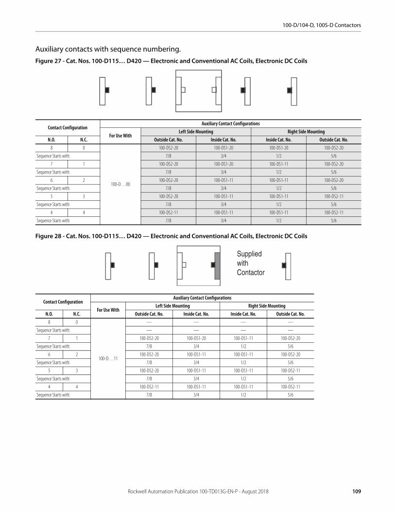
100-D/104-D, 100S-D Contactors
Auxiliary contacts with sequence numbering.Figure 27 - Cat. Nos. 100-D115… D420 — Electronic and Conventional AC Coils, Electronic DC Coils
Figure 28 - Cat. Nos. 100-D115… D420 — Electronic and Conventional AC Coils, Electronic DC Coils
Contact ConfigurationAuxiliary Contact Configurations
For Use WithLeft Side Mounting Right Side Mounting
N.O. N.C. Outside Cat. No. Inside Cat. No. Inside Cat. No. Outside Cat. No.8 0
100-D…00
100-DS2-20 100-DS1-20 100-DS1-20 100-DS2-20
Sequence Starts with: 7/8 3/4 1/2 5/6
7 1 100-DS2-20 100-DS1-20 100-DS1-11 100-DS2-20
Sequence Starts with: 7/8 3/4 1/2 5/6
6 2 100-DS2-20 100-DS1-11 100-DS1-11 100-DS2-20
Sequence Starts with: 7/8 3/4 1/2 5/6
5 3 100-DS2-20 100-DS1-11 100-DS1-11 100-DS2-11
Sequence Starts with: 7/8 3/4 1/2 5/6
4 4 100-DS2-11 100-DS1-11 100-DS1-11 100-DS2-11
Sequence Starts with: 7/8 3/4 1/2 5/6
Contact ConfigurationAuxiliary Contact Configurations
For Use WithLeft Side Mounting Right Side Mounting
N.O. N.C. Outside Cat. No. Inside Cat. No. Inside Cat. No. Outside Cat. No.8 0
100-D…11
— — — —
Sequence Starts with: — — — —
7 1 100-DS2-20 100-DS1-20 100-DS1-11 100-DS2-20
Sequence Starts with: 7/8 3/4 1/2 5/6
6 2 100-DS2-20 100-DS1-11 100-DS1-11 100-DS2-20
Sequence Starts with: 7/8 3/4 1/2 5/6
5 3 100-DS2-20 100-DS1-11 100-DS1-11 100-DS2-11
Sequence Starts with: 7/8 3/4 1/2 5/6
4 4 100-DS2-11 100-DS1-11 100-DS1-11 100-DS2-11
Sequence Starts with: 7/8 3/4 1/2 5/6
SuppliedwithContactor
Rockwell Automation Publication 100-TD013G-EN-P - August 2018 109

100-D/104-D, 100S-D Contactors
Figure 29 - Cat. Nos. 100-D115… D180 — Conventional DC Coils
Marking Systems (For 100-D115...D860 contactors)
Contact ConfigurationAuxiliary Contact Configurations
For Use WithLeft Side Mounting Right Side Mounting
N.O. N.C. Outside Cat. No. Inside Cat. No. Inside Cat. No. Outside Cat. No.8 0
100-D…22L
— — — —
Sequence Starts with: — — — —
7 1 — — — —
Sequence Starts with: — — — —
6 2 100-DS2-20 100-DS1-11 100-DS1-11(1)
(1) With conventional DC control, the pickup winding must be interconnected with the N.C. late-breaking auxiliary contacts.
100-DS2-20
Sequence Starts with: 7/8 3/4 1/2 5/6
5 3 100-DS2-20 100-DS1-11 100-DS1-11(1) 100-DS2-11
Sequence Starts with: 7/8 3/4 1/2 5/6
4 4 100-DS2-11 100-DS1-11 100-DS1-11(1) 100-DS2-11
Sequence Starts with: 7/8 3/4 1/2 5/6
Description Pkg. Qty.(1)
(1) Must be ordered in multiples of package quantities.
Cat. No.
Label Sheet• 105 self-adhesive paper labels each, 6 x 17 mm 10 100-FMS
Marking Tag Sheet• 160 perforated paper labels each, 6 x 17 mm, to be used with a transparent cover 10 100-FMP
Transparent Cover• To be used with marking tag sheets 100 100-FMC
Marking Tag Adapters• To be used with marking tag: System V4/V5 100 100-FMA1
Marking Tag Adapters• To be used with marking tag: System 1492 W 100 100-FMA2
SuppliedwithContactor
SuppliedwithContactor
110 Rockwell Automation Publication 100-TD013G-EN-P - August 2018

100-D/104-D, 100S-D Contactors
Suppressor Modules
Connecting Components
Description Connection Diagram Suppressor Rating For Use With Cat. No.(3)
(3) Package Quantity = 1
Suppressor Module for Bul. 100-D Contactors• For limiting surge voltage when coil circuits are
interrupted• Supplied as standard on all conventional DC coil
contactors and all electronic coil contactors (as part of the supply module or delivered with separate suppressor module)
RC Module (AC control)For contactors with conventional coil21...48V, 50 Hz;24...55V, 60 Hz
100- D115...100- D180
100-DFSC48
95...110V, 50 Hz;110...127V, 60 Hz
100-DFSC110
180...277V, 50 Hz;208...277V, 60 Hz
100-DFSC240
380...550V, 50 Hz;440...600V, 60 Hz
100-DFSC550
Varistor Modulefor contactors with conventional coil 55V AC
100- D115...100- D420
100-DFSV55
56...136V AC 100-DFSV136
137...277V AC 100-DFSV277
278...600V AC 100-DFSV575
Varistor Modulefor contactors with electronic coil 200...277V AC(1)
(1) For overvoltage category IV (IEC 947 for 100-D...-El) e.g., lightning protection requirements.
100- D115...100- D420 100-DFSV550
380...500V AC(2)
(2) For surge pulse > 1kV
100- D115...100- D300 100-DFSV500
Description Cross- sectionFor Use With
Terminal Connection Cat. No.(1)
(1) Package Quantity = 1
100-D115…180
100-D210…420
100-D630…860
Reversing: Input ConnectionWye-Delta: Main-Delta connection
50 mm2 X — — Terminal Blocks, 100-DTB…Lugs, 100-DL…
100-D180-VLTB
120 mm2 — X — 100-D420-VLTB
350 mm2 — — X Lugs, 100-DL… 100-D860-VL
Reversing: Output Connection Wye-Delta: Delta-Wye connection
50 mm2 X — —
Lugs, 100-DL…
100-D180-VT
120 mm2 — X — 100-D420-VT
350 mm2 — — X 100-D860-VT
50 mm2 X — — Terminal Blocks, 100-DTB… 100-D180-VTTB
Delta-Wye connection if 100-D115…180 is used as a Wye contactor 80 mm2 — X — Terminal Blocks,
100-DTB… 100-D420-VYTB
Wye-Delta: Neutral bridge
— X — — 100-D180-VYU
— — X — — 100-D420-VYU
— — — X — 100-D860-VYU
Power Wiring Kits (for contactors using 100-DL lug kits)
For 100-D115…D100-D180
Reversing 100-DPW180
Two-speed, or changeover 100-D180-VLTB
Wye-Delta/Star-Delta 100-DPY180
For 100-D210…100-D420
Reversing 100-DPW420
Two-speed, or changeover 100-D420-VLTB
Wye-Delta/Star-Delta 100-DPY420
For 100-D630…100-D860Reversing 100-DPW860
Two-speed, or changeover 100-D860-VL
Rockwell Automation Publication 100-TD013G-EN-P - August 2018 111
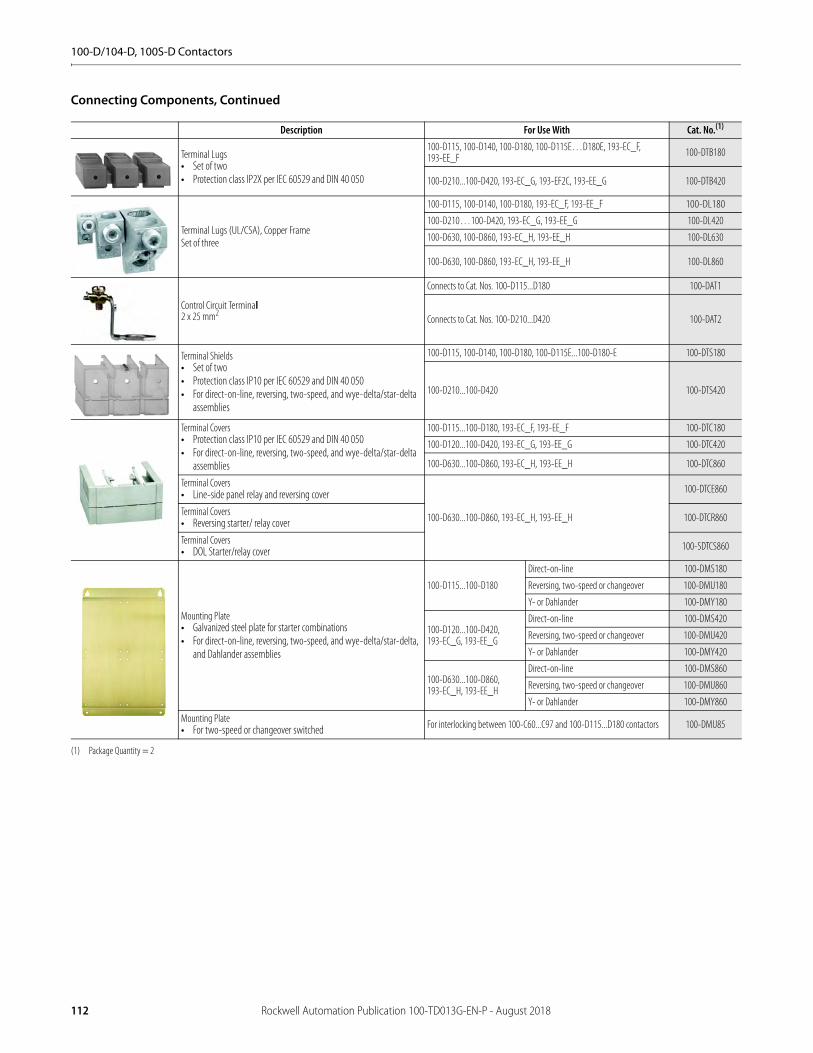
100-D/104-D, 100S-D Contactors
Connecting Components, Continued
Description For Use With Cat. No.(1)
(1) Package Quantity = 2
Terminal Lugs• Set of two• Protection class IP2X per IEC 60529 and DIN 40 050
100-D115, 100-D140, 100-D180, 100-D115E…D180E, 193-EC_F, 193-EE_F 100-DTB180
100-D210...100-D420, 193-EC_G, 193-EF2C, 193-EE_G 100-DTB420
Terminal Lugs (UL/CSA), Copper FrameSet of three
100-D115, 100-D140, 100-D180, 193-EC_F, 193-EE_F 100-DL180
100-D210…100-D420, 193-EC_G, 193-EE_G 100-DL420
100-D630, 100-D860, 193-EC_H, 193-EE_H 100-DL630
100-D630, 100-D860, 193-EC_H, 193-EE_H 100-DL860
Control Circuit Terminal2 x 25 mm2
Connects to Cat. Nos. 100-D115...D180 100-DAT1
Connects to Cat. Nos. 100-D210...D420 100-DAT2
Terminal Shields• Set of two• Protection class IP10 per IEC 60529 and DIN 40 050• For direct-on-line, reversing, two-speed, and wye-delta/star-delta
assemblies
100-D115, 100-D140, 100-D180, 100-D115E...100-D180-E 100-DTS180
100-D210...100-D420 100-DTS420
Terminal Covers• Protection class IP10 per IEC 60529 and DIN 40 050• For direct-on-line, reversing, two-speed, and wye-delta/star-delta
assemblies
100-D115...100-D180, 193-EC_F, 193-EE_F 100-DTC180
100-D120...100-D420, 193-EC_G, 193-EE_G 100-DTC420
100-D630...100-D860, 193-EC_H, 193-EE_H 100-DTC860
Terminal Covers• Line-side panel relay and reversing cover
100-D630...100-D860, 193-EC_H, 193-EE_H
100-DTCE860
Terminal Covers• Reversing starter/ relay cover 100-DTCR860
Terminal Covers• DOL Starter/relay cover 100-SDTCS860
Mounting Plate• Galvanized steel plate for starter combinations• For direct-on-line, reversing, two-speed, and wye-delta/star-delta,
and Dahlander assemblies
100-D115...100-D180
Direct-on-line 100-DMS180
Reversing, two-speed or changeover 100-DMU180
Y- or Dahlander 100-DMY180
100-D120...100-D420, 193-EC_G, 193-EE_G
Direct-on-line 100-DMS420
Reversing, two-speed or changeover 100-DMU420
Y- or Dahlander 100-DMY420
100-D630...100-D860, 193-EC_H, 193-EE_H
Direct-on-line 100-DMS860
Reversing, two-speed or changeover 100-DMU860
Y- or Dahlander 100-DMY860
Mounting Plate• For two-speed or changeover switched For interlocking between 100-C60...C97 and 100-D115...D180 contactors 100-DMU85
112 Rockwell Automation Publication 100-TD013G-EN-P - August 2018
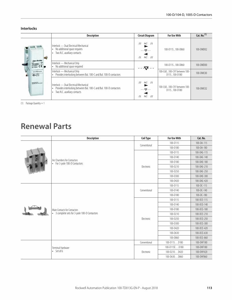
100-D/104-D, 100S-D Contactors
Interlocks
Renewal Parts
Description Circuit Diagram For Use With Cat. No.(1)
(1) Package Quantity = 1
Interlock — Dual Electrical/Mechanical• No additional space requires• Two N.C. auxiliary contacts
100-D115...100-D860 100-DMD02
Interlock — Mechanical Only• No additional space required 100-D115...100-D860 100-DMD00
Interlock — Mechanical Only• Provides interlocking between Bul. 100-C and Bul. 100-D contactors
100-C60...100-C97 between 100-D115...100-D180 100-DMC00
Interlock — Dual Electrical/Mechanical• Provides interlocking between Bul. 100-C and Bul. 100-D contactors• Two N.C. auxiliary contacts
100-C60...100-C97 between 100-D115...100-D180 100-DMC02
Description Coil Type For Use With Cat. No.
Arc Chambers for Contactors• For 3-pole 100-D Contactors
Conventional100-D115 100-DA-115
100-D180 100-DA-180
Electronic
100-D115 100-DAE-115
100-D140 100-DAE-140
100-D180 100-DAE-180
100-D210 100-DAE-210
100-D250 100-DAE-250
100-D300 100-DAE-300
100-D420 100-DAE-420
Main Contacts for Contactors• 3 complete sets for 3-pole 100-D Contactors
Conventional
100-D115 100-DC-115
100-D140 100-DC-140
100-D180 100-DC-180
Electronic
100-D115 100-DCE-115
100-D140 100-DCE-140
100-D180 100-DCE-180
100-D210 100-DCE-210
100-D250 100-DCE-250
100-D300 100-DCE-300
100-D420 100-DCE-420
100-D630 100-DCE-630
100-D860 100-DCE-860
Terminal Hardware• Set of 6
Conventional 100-D115…D180 100-DHF180
Electronic
100-D115E…D180 100-DHF180
100-D210…D420 100-DHF420
100-D630…D860 100-DHF860
22 NC 21
21 NC 22
22 NC 21
21 NC 22
Rockwell Automation Publication 100-TD013G-EN-P - August 2018 113

100-D/104-D, 100S-D Contactors
Replacement Coils
Conventional AC Coils Conventional DC Coils
AC Standard Control Voltages [V] AC Coil Code
100-D95…D180
100-D210…D420
100-D630…D860
DC Standard Control
Voltages [V]DC Coil Code
100-D95…D180
100-D210…D420
100-D630…D860
50 Hz 60 Hz 50/60 Hz Cat. No. Cat. No. Cat. No. Cat. No. Cat. No. Cat. No.24V — — K TG407 — — 24V ZJ TG714 — —
— 24V — J TG013 — — 48V ZY TG724 — —
48V — — Y TG414 — — 110V ZD TG733 — —
42V 48V — X TG482 — — 125V ZS TG737 — —
— — 100V(1)
(1) Applies to 100-D95…-D115 contactors only. Not available with 100-D140…-D180 contactors.
KP TG861 — — 220V ZA TG761 — —
110V 120V — D TG473 — —
— — 110V(1) KN TG856 — —
— 208V — H TG049 — —
— — 200V(1) KG TG862 — —
— — 220V(1) KL TG857 — —
220…230V 240V — A TG441 — —
240V 277V — T TG480 — —
— — 277V(1) KT TG060 — —
— — 230V(1) KF TG851 — —
— — 240V(1) KA TG858 — —
380…400V 440V — N TG071 — —
415V 480V — B TG475 — —
440V — — G TG478 — —
500V — — M TG479 — —
550V 600V — C TG476 — —
Electronic AC Coils Electronic DC Coils
AC Standard Control Voltages [V] AC Coil Code
100-D95…D180
100-D210…D420
100-D630…D860
DC Standard Control
Voltages [V]DC Coil Code
100-D95…D180
100-D210…D420
100-D630…D860
50 Hz 60 Hz 50/60 Hz Cat. No. Cat. No. Cat. No. Cat. No. Cat. No. Cat. No.— — 24V EJ(2)
(2) Not available on 100/104?]D300
TGE855 — — 24V EZJ TGE708 — —
— — 42…64V EY TGE864 — — 48…72V EZY TGE779 — —
— — 100V EP TGE861 THE861 TJE861110…130V
EZD TGE780 THE780 —
— — 110…130V ED TGE865 THE865 TJE865 ED — — TJE865
— — 200V EG TGE862 THE862 —200…255V
EZA TGE781 THE781 —
— — 208…277V EA TGE866 THE866 — EA — — TJE879
— — 200…220V EG — — TJE878
— — 230…250V EA — — TJE879
— — 380…500V EN TGE867 THE867 —
— — 380…415V EN — — TJE867
— — 440…480V EB — — TJE868
— — 500V EM — — TJE869
114 Rockwell Automation Publication 100-TD013G-EN-P - August 2018
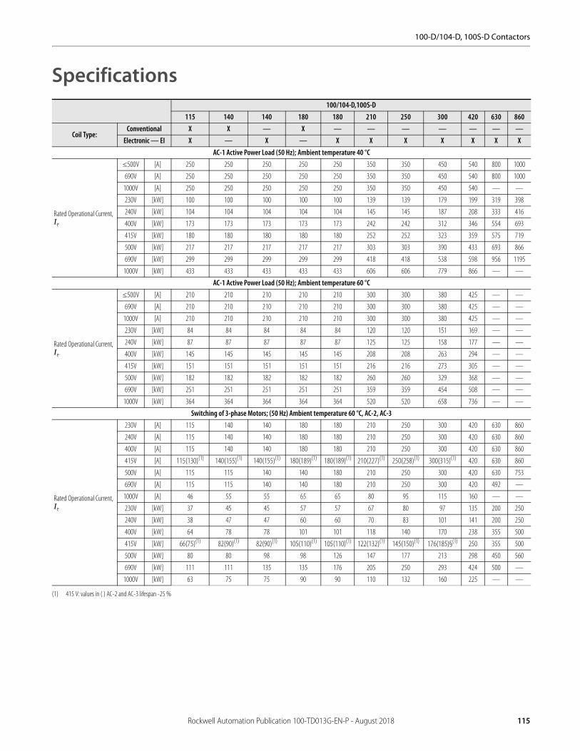
100-D/104-D, 100S-D Contactors
Specifications100/104-D,100S-D
115 140 140 180 180 210 250 300 420 630 860
Coil Type:Conventional X X — X — — — — — — —
Electronic — EI X — X — X X X X X X XAC-1 Active Power Load (50 Hz); Ambient temperature 40 °C
Rated Operational Current, Ie
≤500V [A] 250 250 250 250 250 350 350 450 540 800 1000
690V [A] 250 250 250 250 250 350 350 450 540 800 1000
1000V [A] 250 250 250 250 250 350 350 450 540 — —
230V [kW] 100 100 100 100 100 139 139 179 199 319 398
240V [kW] 104 104 104 104 104 145 145 187 208 333 416
400V [kW] 173 173 173 173 173 242 242 312 346 554 693
415V [kW] 180 180 180 180 180 252 252 323 359 575 719
500V [kW] 217 217 217 217 217 303 303 390 433 693 866
690V [kW] 299 299 299 299 299 418 418 538 598 956 1195
1000V [kW] 433 433 433 433 433 606 606 779 866 — —
AC-1 Active Power Load (50 Hz); Ambient temperature 60 °C
Rated Operational Current, Ie
≤500V [A] 210 210 210 210 210 300 300 380 425 — —
690V [A] 210 210 210 210 210 300 300 380 425 — —
1000V [A] 210 210 210 210 210 300 300 380 425 — —
230V [kW] 84 84 84 84 84 120 120 151 169 — —
240V [kW] 87 87 87 87 87 125 125 158 177 — —
400V [kW] 145 145 145 145 145 208 208 263 294 — —
415V [kW] 151 151 151 151 151 216 216 273 305 — —
500V [kW] 182 182 182 182 182 260 260 329 368 — —
690V [kW] 251 251 251 251 251 359 359 454 508 — —
1000V [kW] 364 364 364 364 364 520 520 658 736 — —
Switching of 3-phase Motors; (50 Hz) Ambient temperature 60 °C, AC-2, AC-3
Rated Operational Current, Ie
230V [A] 115 140 140 180 180 210 250 300 420 630 860
240V [A] 115 140 140 180 180 210 250 300 420 630 860
400V [A] 115 140 140 180 180 210 250 300 420 630 860
415V [A] 115(130)(1)
(1) 415 V: values in ( ) AC-2 and AC-3 lifespan -25 %
140(155)(1) 140(155)(1) 180(189)(1) 180(189)(1) 210(227)(1) 250(258)(1) 300(315)(1) 420 630 860
500V [A] 115 115 140 140 180 210 250 300 420 630 753
690V [A] 115 115 140 140 180 210 250 300 420 492 —
1000V [A] 46 55 55 65 65 80 95 115 160 — —
230V [kW] 37 45 45 57 57 67 80 97 135 200 250
240V [kW] 38 47 47 60 60 70 83 101 141 200 250
400V [kW] 64 78 78 101 101 118 140 170 238 355 500
415V [kW] 66(75)(1) 82(90)(1) 82(90)(1) 105(110)(1) 105(110)(1) 122(132)(1) 145(150)(1) 176(185)§(1) 250 355 500
500V [kW] 80 80 98 98 126 147 177 213 298 450 560
690V [kW] 111 111 135 135 176 205 250 293 424 500 —
1000V [kW] 63 75 75 90 90 110 132 160 225 — —
Rockwell Automation Publication 100-TD013G-EN-P - August 2018 115
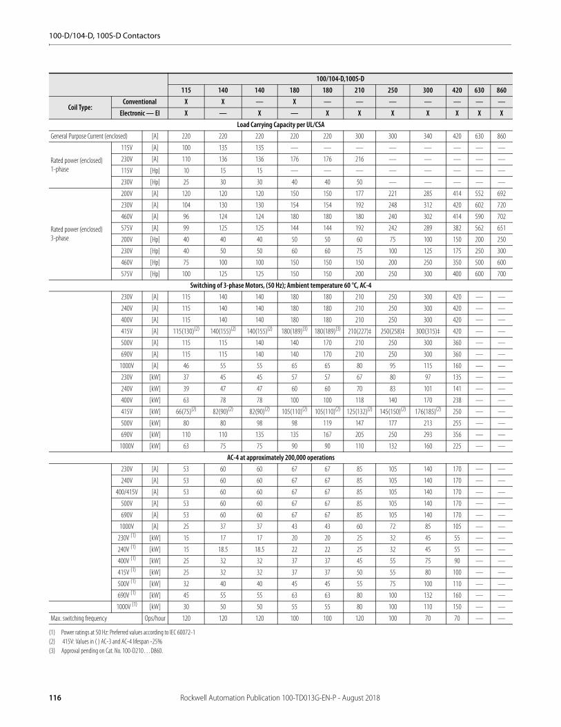
100-D/104-D, 100S-D Contactors
100/104-D,100S-D115 140 140 180 180 210 250 300 420 630 860
Coil Type:Conventional X X — X — — — — — — —
Electronic — EI X — X — X X X X X X XLoad Carrying Capacity per UL/CSA
General Purpose Current (enclosed) [A] 220 220 220 220 220 300 300 340 420 630 860
Rated power (enclosed)1-phase
115V [A] 100 135 135 — — — — — — — —
230V [A] 110 136 136 176 176 216 — — — — —
115V [Hp] 10 15 15 — — — — — — — —
230V [Hp] 25 30 30 40 40 50 — — — — —
Rated power (enclosed)3-phase
200V [A] 120 120 120 150 150 177 221 285 414 552 692
230V [A] 104 130 130 154 154 192 248 312 420 602 720
460V [A] 96 124 124 180 180 180 240 302 414 590 702
575V [A] 99 125 125 144 144 192 242 289 382 562 651
200V [Hp] 40 40 40 50 50 60 75 100 150 200 250
230V [Hp] 40 50 50 60 60 75 100 125 175 250 300
460V [Hp] 75 100 100 150 150 150 200 250 350 500 600
575V [Hp] 100 125 125 150 150 200 250 300 400 600 700
Switching of 3-phase Motors, (50 Hz); Ambient temperature 60 °C, AC-4230V [A] 115 140 140 180 180 210 250 300 420 — —
240V [A] 115 140 140 180 180 210 250 300 420 — —
400V [A] 115 140 140 180 180 210 250 300 420 — —
415V [A] 115(130)(2)
(2) 415V: Values in ( ) AC-3 and AC-4 lifespan -25%
140(155)(2) 140(155)(2) 180(189)(3)
(3) Approval pending on Cat. No. 100-D210…D860.
180(189)(3) 210(227)‡ 250(258)‡ 300(315)‡ 420 — —
500V [A] 115 115 140 140 170 210 250 300 360 — —
690V [A] 115 115 140 140 170 210 250 300 360 — —
1000V [A] 46 55 55 65 65 80 95 115 160 — —
230V [kW] 37 45 45 57 57 67 80 97 135 — —
240V [kW] 39 47 47 60 60 70 83 101 141 — —
400V [kW] 63 78 78 100 100 118 140 170 238 — —
415V [kW] 66(75)(2) 82(90)(2) 82(90)(2) 105(110)(2) 105(110)(2) 125(132)(2) 145(150)(2) 176(185)(2) 250 — —
500V [kW] 80 80 98 98 119 147 177 213 255 — —
690V [kW] 110 110 135 135 167 205 250 293 356 — —
1000V [kW] 63 75 75 90 90 110 132 160 225 — —
AC-4 at approximately 200,000 operations230V [A] 53 60 60 67 67 85 105 140 170 — —
240V [A] 53 60 60 67 67 85 105 140 170 — —
400/415V [A] 53 60 60 67 67 85 105 140 170 — —
500V [A] 53 60 60 67 67 85 105 140 170 — —
690V [A] 53 60 60 67 67 85 105 140 170 — —
1000V [A] 25 37 37 43 43 60 72 85 105 — —
230V (1)
(1) Power ratings at 50 Hz: Preferred values according to IEC 60072-1
[kW] 15 17 17 20 20 25 32 45 55 — —
240V (1) [kW] 15 18.5 18.5 22 22 25 32 45 55 — —
400V (1) [kW] 25 32 32 37 37 45 55 75 90 — —
415V (1) [kW] 25 32 32 37 37 50 55 80 100 — —
500V (1) [kW] 32 40 40 45 45 55 75 100 110 — —
690V (1) [kW] 45 55 55 63 63 80 100 132 160 — —
1000V (1) [kW] 30 50 50 55 55 80 100 110 150 — —
Max. switching frequency Ops/hour 120 120 120 100 100 120 100 70 70 — —
116 Rockwell Automation Publication 100-TD013G-EN-P - August 2018

100-D/104-D, 100S-D Contactors
100/104-D,100S-D115 140 140 180 180 210 250 300 420 630 860
Coil Type:Conventional X X — X — — — — — — —
Electronic — EI X — X — X X X X X X XWye-Delta (60 Hz)
200V [Hp] 60 60 60 75 75 100 125 175 250 — —
230V [Hp] 60 75 75 100 100 125 175 200 250 — —
460V [Hp] 125 175 175 200 200 250 350 450 600 — —
575V [Hp] 150 200 200 250 250 300 450 500 650 — —
UL/CSA Elevator Duty200V [A] 78 92 92 120 120 150 150 177 221 — —
230V [A] 80 104 104 130 130 130 154 192 248 — —
460V [A] 77 96 96 124 124 156 180 180 240 — —
575V [A] 77 77 77 99 99 125 144 192 242 — —
200V [Hp] 25 30 30 40 40 50 50 60 75 — —
230V [Hp] 30 40 40 50 50 50 60 75 100 — —
460V [Hp] 60 75 75 100 100 125 150 150 200 — —
575V [Hp] 75 75 75 100 100 125 150 200 250 — —
Star-Delta Starting (50 Hz)≤ 230V [A] 199 242 242 312 312 364 433 520 727 — —
≤ 240V [A] 199 242 242 312 312 364 433 520 727 — —
400V [A] 199 242 242 312 312 364 433 520 727 — —
415V [A] 199 (225)(2)
(2) 415V: Values in () AC-3 and AC-4 lifespan -25%
242(268)(2) 242 (268)(2) 312 (332)(2) 312 (332)(2) 364 (393)(2) 433 (447)(2) 520 (546)(2) 727 — —
500V [A] 199 199 242 312 312 364 433 520 727 — —
690V [A] 199 199 242 312 312 364 433 520 727 — —
1000V [A] 80 95 95 113 113 139 165 200 277 — —
230V (1)
(1) Power ratings at 50 Hz: Preferred values according to IEC 60072-1
[kW] 63 75 75 90 90 110 132 160 220 — —
240V (1) [kW] 66 80 80 100 100 125 150 160 250 — —
400V (1) [kW] 110 132 132 160 160 200 250 300 425 — —
415V (1) [kW] 114 (132)(2) 132 (160)(2) 132 (160)(2) 160 160 220 250 315 (335)(2) 425 — —
500V (1) [kW] 132 132 160 200 200 250 315 375 530 — —
690V (1) [kW] 192 200 220 300 300 355 425 530 750 — —
1000V(1) [kW] 110 132 132 160 160 200 220 280 400 — —
Rockwell Automation Publication 100-TD013G-EN-P - August 2018 117

100-D/104-D, 100S-D Contactors
100/104-D,100S-D115 140 140 180 180 210 250 300 420 630 860
Coil Type:Conventional X X — X — — — — — — —
Electronic — EI X — X — X X X X X X XSwitching of Power Transformers, AC-6a (50 Hz)
Inrush Current=n
Rated transformer current
n= 30
≤ 230V [A] 60 70 70 85 85 105 125 150 210 — —
≤ 240V [A] 60 70 70 85 85 105 125 150 210 — —
≤ 400V [A] 60 70 70 85 85 105 125 150 210 — —
≤ 415V [A] 60 70 70 85 85 105 125 150 210 — —
≤ 500V [A] 60 70 70 85 85 105 125 150 210 — —
≤ 690V [A] 60 70 70 85 85 105 125 150 210 — —
≤ 1000V [A] 46 70 70 85 85 105 125 150 210 — —
230V [kVA] 24 28 28 34 34 42 50 60 84 — —
240V [kVA] 26 29 29 35 35 44 52 62 87 — —
400V [kVA] 42 48 48 59 59 73 87 104 145 — —
415V [kVA] 43 50 50 61 61 75 90 108 151 — —
500V [kVA] 52 61 61 74 74 91 108 130 182 — —
690V [kVA] 72 84 84 102 102 125 149 179 251 — —
1000V [kVA] 80 121 121 147 147 182 217 260 364 — —
n=20 ≤ 690V [A] 90 105 105 128 128 158 188 225 315 — —
n=15 ≤ 690V [A] 120 140 140 170 170 210 250 300 420 — —
60 Hz Peak Inrush/peak rated transformer currentn=30 [A] 60 70 70 85 85 105 125 150 210 — —
200V [kVA] 20.8 24.2 24.2 29.4 29.4 36.4 43.3 52.0 72.7 — —
208V [kVA] 21.6 25.2 25.2 30.6 30.6 37.8 45.0 54.0 75.7 — —
240V [kVA] 24.9 29.1 29.1 35.3 35.3 43.6 52.0 62.4 87.3 — —
480V [kVA] 49.9 58.2 58.2 70.7 70.7 87.3 104 125 175 — —
600V [kVA] 62.4 72.7 72.7 88.3 88.3 109 130 156 218 — —
660V [kVA] 68.6 80.0 80.0 97.2 97.2 120 143 171 240 — —
60 Hz Peak Inrush/peak rated transformer currentn=20 [A] 90 105 105 128 128 158 188 225 315 — —
200V [kVA] 31.2 36.4 36.4 44.3 44.3 54.7 65.1 77.9 109 — —
208V [kVA] 32.4 37.8 37.8 46.1 46.1 56.9 67.7 81.1 113 — —
240V [kVA] 37.4 43.6 43.6 53.2 53.2 65.7 78.2 93.5 131 — —
480V [kVA] 74.8 87.3 87.3 106 106 131 156 187 262 — —
600V [kVA] 93.5 109 109 133 133 164 195 234 327 — —
660V [kVA] 103 120 120 146 146 131 215 257 360 — —
60 Hz Peak Inrush/peak rated transformer currentn=15 [A] 120 140 140 170 170 210 250 300 420 — —
200V [kVA] 41.6 48.5 48.5 58.9 58.9 72.7 86.6 104 145 — —
208V [kVA] 43.2 50.4 50.4 61.2 61.2 75.7 90.1 108 151 — —
240V [kVA] 49.9 58.2 58.2 70.7 70.7 87.3 104 125 175 — —
480V [kVA] 99.8 116 116 141 141 175 208 249 349 — —
600V [kVA] 125 145 145 177 177 218 260 312 436 — —
660V [kVA] 137 160 160 194 194 240 286 343 480 — —
118 Rockwell Automation Publication 100-TD013G-EN-P - August 2018

100-D/104-D, 100S-D Contactors
100/104-D,100S-D115 140 140 180 180 210 250 300 420 630 860
Coil Type:Conventional X X — X — — — — — — —
Electronic — EI X — X — X X X X X X XSwitching of 3-phase Capacitors, AC-6b (50 Hz)
Single capacitor 40°C
230V [kVar] 45 70 70 70 70 98 98 125 139 — —
240V [kVar] 47 73 73 73 73 102 102 131 145 — —
400V [kVar] 78 121 121 121 121 170 170 218 242 — —
415V [kVar] 81 126 126 126 126 176 176 226 252 — —
500V [kVar] 97 152 152 152 152 212 212 273 303 — —
690V [kVar] 134 209 209 209 209 293 293 376 418 — —
1000V [kVar] 194 303 303 303 303 424 424 546 606 — —
Single capacitor 60 °C
230V [kVar] 38 59 59 59 59 84 84 106 119 — —
240V [kVar] 39 61 61 61 61 87 87 111 124 — —
400V [kVar] 65 102 102 102 102 145 145 184 206 — —
415V [kVar] 68 106 106 106 106 151 151 191 214 — —
500V [kVar] 82 127 127 127 127 182 182 230 258 — —
690V [kVar] 113 176 176 176 176 251 251 318 356 — —
1000V [kVar] 164 255 255 255 255 364 364 461 515 — —
Group capacitors 40°C
230V [kVar] 45 70 70 70 70 98 98 125 139 — —
240V [kVar] 47 73 73 73 73 102 102 131 145 — —
400V [kVar] 56 76 76 111 111 170 170 218 242 — —
415V [kVar] 56 76 76 112 112 170 176 226 252 — —
500V [kVar] 56 76 76 113 113 172 212 273 303 — —
690V [kVar] 57 78 78 114 114 174 247 356 418 — —
1000V [kVar] 58 79 79 116 116 177 251 361 606 — —
Group capacitors 60 °C
230V [kVar] 38 59 59 59 59 84 84 106 119 — —
240V [kVar] 39 61 61 61 61 87 87 111 124 — —
400V [kVar] 56 76 76 102 102 145 145 184 206 — —
415V [kVar] 56 76 76 106 106 151 151 191 214 — —
500V [kVar] 56 76 76 113 113 172 182 230 258 — —
690V [kVar] 57 78 78 114 114 174 247 318 356 — —
1000V [kVar] 58 79 79 116 116 177 251 361 515 — —
60 Hz Single Capacitor — 40 °C
200V [kVar] 39 61 61 61 61 85 85 109 121 — —
230V [kVar] 45 70 70 70 70 98 98 125 139 — —
460V [kVar] 89 139 139 139 139 195 195 251 279 — —
600V [kVar] 116 182 182 182 182 255 255 327 364 — —
60 Hz Group Capacitors — 40 °C
200V [kVar] 39 61 61 61 61 85 85 109 121 — —
230V [kVar] 45 70 70 70 70 98 98 125 139 — —
460V [kVar] 56 76 76 112 112 171 195 251 279 — —
600V [kVar] 57 77 77 114 114 173 246 327 364 — —
Switching of LampsGas discharge lamps AC-5a, 40 °C
open [A] 144 225 225 225 225 315 315 405 450 — —
enclosed [A] 122 189 189 189 189 270 270 342 383 — —
Individually compensated:
Max. capacitance at expected
Filament AC-5b 230/240V [A] 120 140 140 170 170 210 250 300 420 — —
Rockwell Automation Publication 100-TD013G-EN-P - August 2018 119
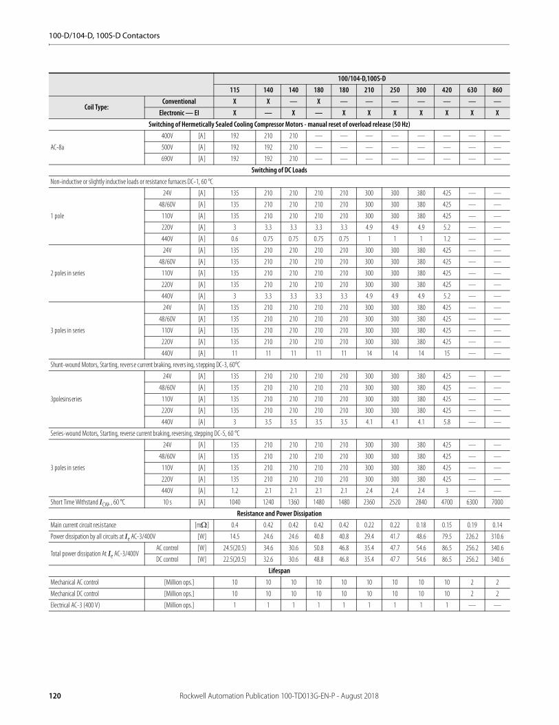
100-D/104-D, 100S-D Contactors
100/104-D,100S-D115 140 140 180 180 210 250 300 420 630 860
Coil Type:Conventional X X — X — — — — — — —
Electronic — EI X — X — X X X X X X XSwitching of Hermetically Sealed Cooling Compressor Motors - manual reset of overload release (50 Hz)
AC-8a
400V [A] 192 210 210 — — — — — — — —
500V [A] 192 192 210 — — — — — — — —
690V [A] 192 192 210 — — — — — — — —
Switching of DC LoadsNon-inductive or slightly inductive loads or resistance furnaces DC-1, 60 °C
1 pole
24V [A] 135 210 210 210 210 300 300 380 425 — —
48/60V [A] 135 210 210 210 210 300 300 380 425 — —
110V [A] 135 210 210 210 210 300 300 380 425 — —
220V [A] 3 3.3 3.3 3.3 3.3 4.9 4.9 4.9 5.2 — —
440V [A] 0.6 0.75 0.75 0.75 0.75 1 1 1 1.2 — —
2 poles in series
24V [A] 135 210 210 210 210 300 300 380 425 — —
48/60V [A] 135 210 210 210 210 300 300 380 425 — —
110V [A] 135 210 210 210 210 300 300 380 425 — —
220V [A] 135 210 210 210 210 300 300 380 425 — —
440V [A] 3 3.3 3.3 3.3 3.3 4.9 4.9 4.9 5.2 — —
3 poles in series
24V [A] 135 210 210 210 210 300 300 380 425 — —
48/60V [A] 135 210 210 210 210 300 300 380 425 — —
110V [A] 135 210 210 210 210 300 300 380 425 — —
220V [A] 135 210 210 210 210 300 300 380 425 — —
440V [A] 11 11 11 11 11 14 14 14 15 — —
Shunt-wound Motors, Starting, reverse current braking, revers ing, s tepping DC-3, 60°C
3polesinseries
24V [A] 135 210 210 210 210 300 300 380 425 — —
48/60V [A] 135 210 210 210 210 300 300 380 425 — —
110V [A] 135 210 210 210 210 300 300 380 425 — —
220V [A] 135 210 210 210 210 300 300 380 425 — —
440V [A] 3 3.5 3.5 3.5 3.5 4.1 4.1 4.1 5.8 — —
Series-wound Motors, Starting, reverse current braking, reversing, stepping DC-5, 60 °C
3 poles in series
24V [A] 135 210 210 210 210 300 300 380 425 — —
48/60V [A] 135 210 210 210 210 300 300 380 425 — —
110V [A] 135 210 210 210 210 300 300 380 425 — —
220V [A] 135 210 210 210 210 300 300 380 425 — —
440V [A] 1.2 2.1 2.1 2.1 2.1 2.4 2.4 2.4 3 — —
Short Time Withstand ICW, , 60 °C 10 s [A] 1040 1240 1360 1480 1480 2360 2520 2840 4700 6300 7000
Resistance and Power DissipationMain current circuit resistance [m] 0.4 0.42 0.42 0.42 0.42 0.22 0.22 0.18 0.15 0.19 0.14
Power dissipation by all circuits at Ie AC-3/400V [W] 14.5 24.6 24.6 40.8 40.8 29.4 41.7 48.6 79.5 226.2 310.6
Total power dissipation At Ie AC-3/400VAC control [W] 24.5(20.5) 34.6 30.6 50.8 46.8 35.4 47.7 54.6 86.5 256.2 340.6
DC control [W] 22.5(20.5) 32.6 30.6 48.8 46.8 35.4 47.7 54.6 86.5 256.2 340.6
LifespanMechanical AC control [Million ops.] 10 10 10 10 10 10 10 10 10 2 2
Mechanical DC control [Million ops.] 10 10 10 10 10 10 10 10 10 2 2
Electrical AC-3 (400 V) [Million ops.] 1 1 1 1 1 1 1 1 1 — —
120 Rockwell Automation Publication 100-TD013G-EN-P - August 2018

100-D/104-D, 100S-D Contactors
100/104-D,100S-D115 140 140 180 180 210 250 300 420 630 860
Coil Type:Conventional X X — X — — — — — — —
Electronic — EI X — X — X X X X X X XWeight
ACNon-Rev. [kg (lbs)] 3.3(7.28)
[3.8 (8.38)](1)
(1) Values in brackets refer to electronic coil (EI) version.
3.3 (7.28) 3.8 (8.38) 3.3 (7.28) 3.8 (8.38) 7.5 (16.53) 7.5 (16.53) 7.5 (16.53) 7.5 (16.53) 28.6 (63) 28.6 (63)
Rev. [kg (lbs)] 3.14 (6.92) — — — — — — — — — —
DCNon-Rev. [kg (lbs)] 3.3(7.28)
[3.8 (8.38)](1) 3.3 (7.28) 3.8 (8.38) 3.3 (7.28) 3.8 (8.38) 7.5 (16.53) 7.5 (16.53) 7.5 (16.53) 7.5 (16.53) 28.6 (63) 28.6 (63)
Rev. [kg (lbs)] 3.22(7.1) — — — — — — — — — —
100/104-D,100S-D115 140 180 210 250 300 420 630 860
Coil Type:Conventional X X X — — — — — —
Electronic — EI X X X X X X X X X
Conductor Cross Sections - Main Contacts Terminal type(1)
(1) Hexagonal socket screw
(1) (1)
b max. [mm] 25 30 52
c max. [mm] 12.5 15 22
s max. [mm] 5 6 2 x 8
min. [mm] 8.3 10.5 13
Recommended torque [N•m] 22 43 68
Recommended torque [lb-in] 195 380 600
With terminal lug kit 100-DL180(1) 100-DL420(1) 100-DL630 100-DL860
Cros s s ection per UL/CSA [AWG] 6…300 MCM (2x) 4…350 MCM (2X) 2/0…500 MCM (4X) 2/0…500 MCM
Recommended torque [lb-in] 88…106 375 400 400
With Frame Terminal Block 100-DTB180(1) 100-DTB420(2)
(2) Pozidriv No. 2 / Blade No. 3 screw
— —
top opening [mm2] 16…35 25…185 — —
bottom opening [mm2] 16…95 25…185 — —
top opening [mm2] 16…50 25…240 — —
bottom opening [mm2] 16…120 25…240 — —
b max. [mm] 20 25 — —
s top [mm] 3…9 6…20 — —
s bottom [mm] 3…14 6…20 — —
Recommended torque [N•m] 14 25 — —
Cros s s ection per UL/CSAtop [AWG] 6…1/0 AWG 4 AWG…600 MCM — —
bottom [AWG] 6 AWG…250 MCM 4 AWG…600 MCM — —
Recommended torque [lb-in] 124 220 — —
Rockwell Automation Publication 100-TD013G-EN-P - August 2018 121

100-D/104-D, 100S-D Contactors
Short-Circuit Coordination Data
See www.rockwellautomation.com/global/support/global-sccr.page for complete short-circuit current ratings.
100/104-D,100S-D115 140/180 140 180 210 250 300 420 630 860
Coil Type:Conventional X X — — — — — — — —Electronic - EI X — X X X X X X X X
Short Circuit Coordination (Max. Fuse or Circuit Breaker Rating) Per IEC 60947-4-1 (contactor and fuses only)DIN Fuses- gG, gL 50 kA Available Fault Current
Type"1"(690V) [A] 250 315 315 355 500 500 630 630 TBD TBD
Type"2"(400V) [A] 200 250 250 315 400 400 500 500 TBD TBD
Type"2"(690V) [A] 200 250 250 315 400 400 500 500 TBD TBD
BS88Fuses
Type"1"(415V) [A] 200 250 250 250 355 355 450 630 TBD TBD
Type"2"(415V) [A] 200 250 250 250 355 355 450 560 TBD TBD
UL Class K5 and RK5 Fuses 10 kA Available Fault Current
UL Listed Combination (600V) [A] 250 350/450 350 450 500 — — — — —
UL Class L Fuses 18 kA Available Fault Current
UL Listed Combination (600V) [A] — — — — — 700 700 1000 — —
UL Class L Fuses 30 kA Available Fault Current
UL Listed Combination (600V) [A] — — — — — — — — 2000 —
UL Class L Fuses 42 kA Available Fault Current
UL Listed Combination (600V) [A] — — — — — — — — — 2500
UL Class J and CSA HRCI-J Fuses 100 kA Available Fault Current
UL verified combination to IEC60947-4-1 "Type2" [A] 200 250/300 250 300 400 400 500 600 — —
UL Inverse-Time Circuit Breaker 10 kA Available Fault Current
UL Listed Combination (600V) [A] 150 200/250 200 250 300 — — — — —
UL Inverse-Time Circuit Breaker 18 kA Available Fault Current
UL Listed Combination (600V) [A] — — — — — 350 400 500 — —
UL Inverse-Time Circuit Breaker 25 kA Available Fault Current
UL Listed Combination (600Y/347V) [A] 125 200 200 200 250 — — — — —
UL Inverse-Time Circuit Breaker 30 kA Available Fault Current
UL Listed Combination (600V) [A] — — — — — 400 400 600 1200 —
UL Inverse-Time Circuit Breaker 42 kA Available Fault Current
UL Listed Combination (600V) [A] — — — — — — — — — 1200
UL Inverse-Time Circuit Breaker 65 kA Available Fault Current
UL Listed Combination (480V) [A] 125 200 200 200 250 400 400 600 — —
UL Inverse-Time Circuit Breaker 65kAAvailable Fault Current
UL Listed Combination (480V) [A] 125 200 200 200 250 400 400 600 — —
122 Rockwell Automation Publication 100-TD013G-EN-P - August 2018
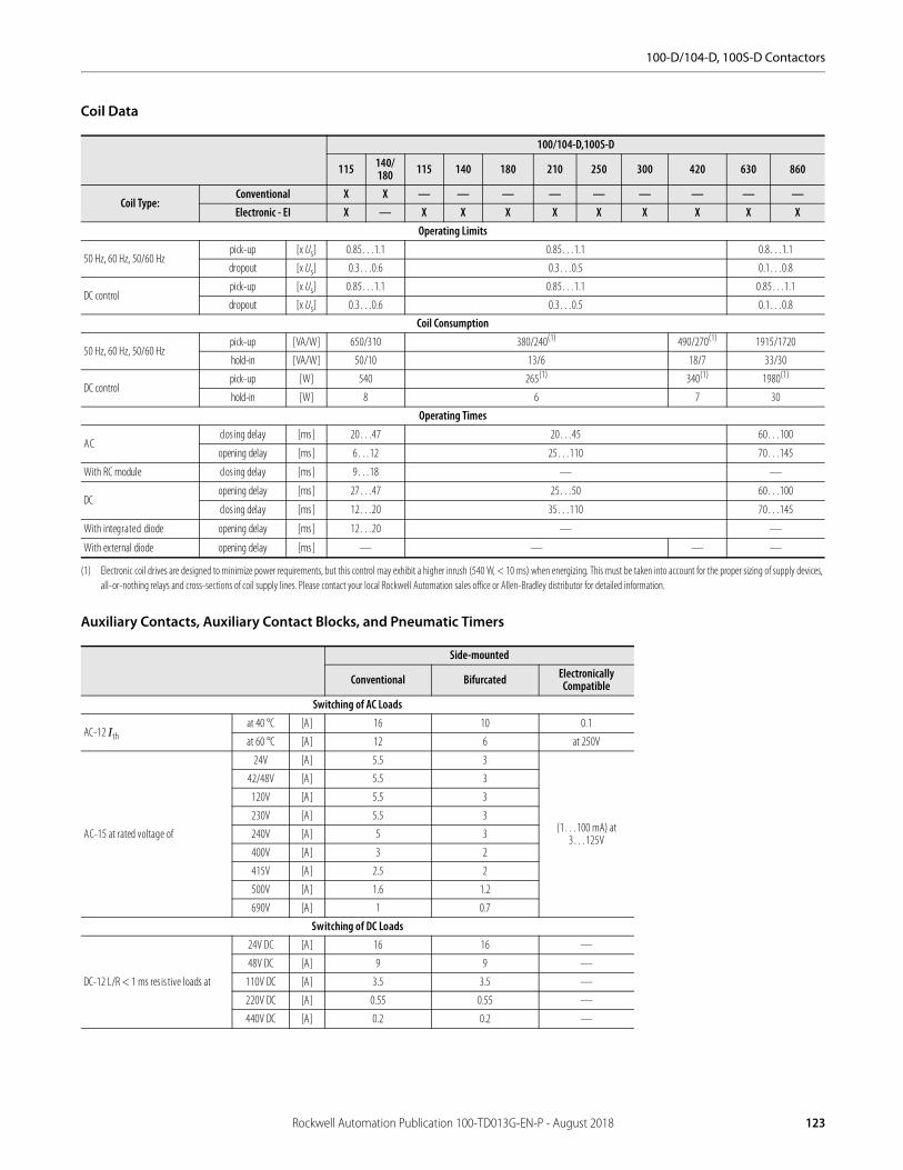
100-D/104-D, 100S-D Contactors
Coil Data
Auxiliary Contacts, Auxiliary Contact Blocks, and Pneumatic Timers
100/104-D,100S-D
115 140/180 115 140 180 210 250 300 420 630 860
Coil Type:Conventional X X — — — — — — — — —Electronic - EI X — X X X X X X X X X
Operating Limits
50 Hz, 60 Hz, 50/60 Hzpick-up [x Us] 0.85…1.1 0.85…1.1 0.8…1.1
dropout [x Us] 0.3…0.6 0.3…0.5 0.1…0.8
DC controlpick-up [x Us] 0.85…1.1 0.85…1.1 0.85…1.1
dropout [x Us] 0.3…0.6 0.3…0.5 0.1…0.8
Coil Consumption
50 Hz, 60 Hz, 50/60 Hzpick-up [VA/W] 650/310 380/240(1)
(1) Electronic coil drives are designed to minimize power requirements, but this control may exhibit a higher inrush (540 W, < 10 ms) when energizing. This must be taken into account for the proper sizing of supply devices, all-or-nothing relays and cross-sections of coil supply lines. Please contact your local Rockwell Automation sales office or Allen-Bradley distributor for detailed information.
490/270(1) 1915/1720
hold-in [VA/W] 50/10 13/6 18/7 33/30
DC controlpick-up [W] 540 265(1) 340(1) 1980(1)
hold-in [W] 8 6 7 30
Operating Times
ACclos ing delay [ms] 20…47 20…45 60…100
opening delay [ms] 6…12 25…110 70…145
With RC module clos ing delay [ms] 9…18 — —
DCopening delay [ms] 27…47 25…50 60…100
clos ing delay [ms] 12…20 35…110 70…145
With integrated diode opening delay [ms] 12…20 — —
With external diode opening delay [ms] — — — —
Side-mounted
Conventional Bifurcated Electronically Compatible
Switching of AC Loads
AC-12 Ithat 40 °C [A] 16 10 0.1
at 60 °C [A] 12 6 at 250V
AC-15 at rated voltage of
24V [A] 5.5 3
(1…100 mA) at 3…125V
42/48V [A] 5.5 3
120V [A] 5.5 3
230V [A] 5.5 3
240V [A] 5 3
400V [A] 3 2
415V [A] 2.5 2
500V [A] 1.6 1.2
690V [A] 1 0.7
Switching of DC Loads
DC-12 L/R < 1 ms res is tive loads at
24V DC [A] 16 16 —
48V DC [A] 9 9 —
110V DC [A] 3.5 3.5 —
220V DC [A] 0.55 0.55 —
440V DC [A] 0.2 0.2 —
Rockwell Automation Publication 100-TD013G-EN-P - August 2018 123
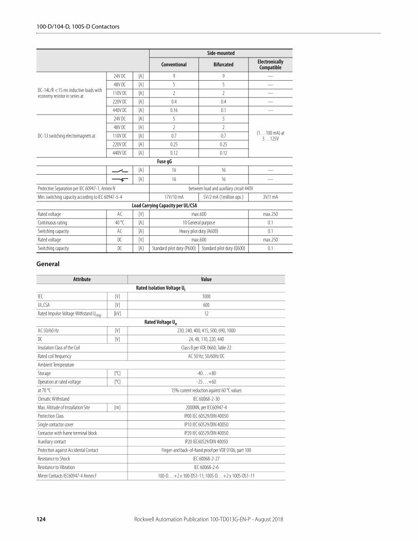
100-D/104-D, 100S-D Contactors
General
DC-14L/R <15 ms inductive loads with economy resistor in series at
24V DC [A] 9 9 —
48V DC [A] 5 5 —
110V DC [A] 2 2 —
220V DC [A] 0.4 0.4 —
440V DC [A] 0.16 0.1 —
DC-13 switching electromagnets at
24V DC [A] 5 5
(1…100 mA) at 3…125V
48V DC [A] 2 2
110V DC [A] 0.7 0.7
220V DC [A] 0.25 0.25
440V DC [A] 0.12 0.12
Fuse gG[A] 16 16 —
[A] 16 16 —
Protective Separation per IEC 60947-1, Annex N between load and auxiliary circuit 440V
Min. switching capacity according to IEC 60947-5-4 17V/10 mA 5V/2 mA (1million ops.) 3V/1 mA
Load Carrying Capacity per UL/CSARated voltage AC [V] max.600 max.250
Continuous rating 40 °C [A] 10 General purpose 0.1
Switching capacity AC [A] Heavy pilot duty (A600) 0.1
Rated voltage DC [V] max.600 max.250
Switching capacity DC [A] Standard pilot duty (P600) Standard pilot duty (Q600) 0.1
Attribute ValueRated Isolation Voltage Ui
IEC [V] 1000
UL,CSA [V] 600
Rated Impulse Voltage Withstand Uimp [kV] 12
Rated Voltage Ue
AC 50/60 Hz [V] 230, 240, 400, 415, 500, 690, 1000
DC [V] 24, 48, 110, 220, 440
Insulation Class of the Coil Class B per VDE 0660, Table 22
Rated coil frequency AC 50 Hz; 50/60Hz DC
Ambient Temperature
Storage [°C] -40…+80
Operation at rated voltage [°C] -25…+60
at 70 °C 15% current reduction against 60 °C values
Climatic Withstand IEC 60068-2-30
Max. Altitude of Installation Site [m] 2000NN, per IEC60947-4
Protection Class IP00 IEC 60529/DIN 40050
Single contactor cover IP10 IEC 60529/DIN 40050
Contactor with frame terminal block IP20 IEC 60529/DIN 40050
Auxiliary contact IP20 IEC60529/DIN 40050
Protection against Accidental Contact Finger-and back-of-hand proof per VDE 0106, part 100
Resistance to Shock IEC 60068-2-27
Resistance to Vibration IEC 60068-2-6
Mirror Contacts IEC60947-4 Annex F 100-D…+2 x 100-DS1-11; 100S-D…+2 x 100S-DS1-11
Side-mounted
Conventional Bifurcated Electronically Compatible
124 Rockwell Automation Publication 100-TD013G-EN-P - August 2018

100-D/104-D, 100S-D Contactors
Standards Compliance and Certifications
100-D IEC Contactors
100S-D Safety Contactors
Life-Load CurvesFigure 30 - AC-3, AC-1
Standards Compliance Certifications
IEC 60947-4-1 CE Marked
IEC 60947 Type “2” Coordination CCC (115…180 A - conventional coil; 115…860 A - electronic coil)
CSA 22.2. No. 14 cULus Listed (File No. E 41850, Guide NLDX, NLDX7)
UL 508
Standards Compliance Certifications
IEC 60947-4-1 CE Marked
IEC 60947-4 Annex F cULus Listed (File No. E 41850, Guide NLDX, NLDX7)
IEC 60947 Type “2” Coordination SUVA Certified
CSA C22.2 No. 14 CCC (115…180 A - conventional coil; 115…860 A - electronic coil)
UL 508
Electrical life span AC-3 Switching of squirrel-cage motors while starting
AC-1 Non- or slightly inductive loads, resistance furnaces, Ue = 415V AC
0.10
1.00
10.00
000100101
Rated operating current Ie AC-3 [A](Dashed curves - - - - - AC-1 only, open)
Cont
act l
ife
[Mio
. of o
ps.]
100-D115
100-D140
100-D180
100-D210
100-D250
100-D300
100-D420
100-D115 AC-1
100-D140 AC-1
100-D180 AC-1
100-D210 AC-1
100-D250 AC-1
100-D300 AC-1
100-D420 AC-1
Rockwell Automation Publication 100-TD013G-EN-P - August 2018 125
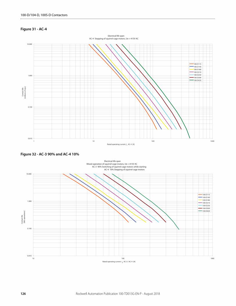
100-D/104-D, 100S-D Contactors
Figure 31 - AC-4
Figure 32 - AC-3 90% and AC-4 10%
Electrical life spanAC-4 Stepping of squirrel-cage motors, Ue = 415V AC
0.010
0.100
1.000
10.000
0001001011
Rated operating current, Ie AC-4 [A]
Cont
act l
ife
[mill
ions
of o
ps.]
100-D115100-D140100-D180100-D210100-D250100-D300100-D420
Electrical life spanMixed operation of squirrel-cage motors, Ue = 415V AC
AC-3 90% Switching of squirrel-cage motors while starting AC-4 10% Stepping of squirrel-cage motors
0.010
0.100
1.000
10.000
10 100 1000
Rated operating current Ie AC-3 / AC-4 [A]
Cont
act l
ife
[Mil.
ope
ratio
ns]
100-D115100-D140100-D180100-D210100-D250100-D300100-D420
126 Rockwell Automation Publication 100-TD013G-EN-P - August 2018

100-D/104-D, 100S-D Contactors
Approximate DimensionsDimensions are shown in millimeters (inches). Dimensions are not intended for manufacturing purposes.
Bulletin 100-D/104-D, 100S-D Approximate Dimensions
Figure 33 - Bulletin 100-D/100S-D Contactors and Accessories
Figure 34 - Mounting Position, 100-D, 100S-D, 104-D Contactors
Contactors with Accessories
AC and DC Contactors
d2
a c
e1
e2 c1
øe
bd1 e3e4
ød
(1)
(1) Conventional DC coil contactors will have an additional auxiliary contact block that will add 13.5 mm to the “a” dimension on the right-hand side.
90°90°
115°
25°
(1) Applies only to conventional single frequency, conventional DC and electronic coils.
(1)Contactor with mm
Auxiliary contact block 100-DS1…100-DS2…
aa + 13.5 each
Mechanical Interlock 100-DM… a + a
Frame terminal block100-DTB110100-DTB180100-DTB420
b + 7 each b + 7 each
b + 8.5 each
Label holder c…+ 5
Cat. No. a b c c1 d d1 d2 e e1 e2 e3 e4
100-D115E…100-D180E, 100-D115, 100-D140, 100-D180 120 170 156 110.5 5.2 145 100 8.5 20 39 160 10
100-D210E…100-D420E 155 205 180 110.5 6.5 180 130 10.4 25 48 193 12.5
100-D630E…100-D860E 255 310 265 110.5 10 230 225 M12 40 70 291 22
100S-D115E…100S-D180E, 100S-D115, 100S-D140, 100S-D180 120 170 156 110.5 5.2 145 100 8.5 20 39 160 10
100S-D210E…100S-D420E 155 205 180 110.5 6.5 180 130 10.5 25 48 193 12.5
100S-D630E…100S-D860E 255 310 265 110.5 10 230 225 M12 40 70 291 22
Rockwell Automation Publication 100-TD013G-EN-P - August 2018 127
100-D/104-D, 100S-D Contactors
Notes:
128 Rockwell Automation Publication 100-TD013G-EN-P - August 2018

100-G Contactors
Product Selection—100-G Contactors• 315...710 kW, 400V• 350…900 Hp, 460/575V• 3-Pole contactors• 4th add-on neutral switching pole AC and DC control• Horizontal and vertical interlocking Mechanical latching• Meets IEC, CE, and cULus Standards and Certifications
The Bulletin 100-G contactor product family provides reliable switching of motor loads up to 1200 A. A complete range of accessories including auxiliary contacts, mechanical latches, horizontal and vertical interlocks, and 4th add-on neutral switching poles provides maximum flexibility to meet a wide variety of application requirements.
AC and DC Control
Coil Voltage Codes
The Cat. No. as listed is incomplete. Select a coil voltage code from the table below to complete the Cat. No. Example: 120V, 60 Hz: Cat. No. 100-G55022 becomes Cat. No.100-G550KD22.
Rated Operational Current Ie [A] Ratings for switching AC motors - AC-2, AC-3 Auxiliary Contacts
Cat No.40 °C kW (50 Hz)(1)
(1) Preferred values according to IEC 60072-1.
Hp (60 Hz) kW (50 Hz
AC-1 (690V) 230V 400V 500V 690V 200V 230V 460V 575V 400 N.O. N.C.760 160 315 400 500 150 150 350 350 315 2 2 100-G55022
1000 220 400 500 630 200 250 500 500 400 2 2 100-G70022
1100 280 500 630 710 250 300 600 600 500 2 2 100-G86022
1200 315 560 750 850 — — — — 560 2(2)
(2) 1 N.O. contact used in control circuit
2 (3)100-G100012
(3) No UL/cUL
1350 375 710 900 1000 450 450 900 900 710 2 2 100-G120012
AC Voltages [V], Conventional Coil 100…110 110…120 200…220 220…240 345…380 380…415 400…440 440…480100-G550...100-G860 50/60 Hz — KD — KF — KN — KB
DC KD — KF — KN — KB —
AC Voltages [V], Conventional Coil 110…115 110 220…230 220 240 380…400 440 480100-G1000...100-G1200 50/60 Hz KD — KF — KA KN KB KU
DC — ZD(1)
(1) Consult your local Rockwell Automation sales office or Allen-Bradley distributor.
— ZA(1) — — — —
Rockwell Automation Publication 100-TD013G-EN-P - August 2018 129
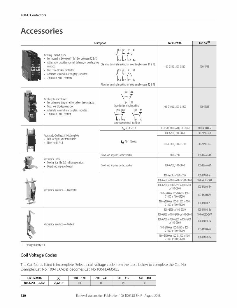
100-G Contactors
Accessories
Coil Voltage Codes
The Cat. No. as listed is incomplete. Select a coil voltage code from the table below to complete the Cat. No. Example: Cat. No. 100-FLAM5 becomes Cat. No.100-FLAM5KD.
Description For Use With Cat. No.(1)
(1) Package Quantity = 1
Auxiliary Contact Block• For mounting between T1 & T2 or between T2 & T3• Adjustable; provides normal, delayed, or overlapping
contacts• Max. two blocks/ contactor• Alternate terminal marking tags included• 2 N.O and 2 N.C. contacts
100-G550...100-G860 100-EF22
Auxiliary Contact Block• For side mounting on either side of the contactor• Max. four blocks/contactor• Alternate terminal marking tags included• 1 N.O and 1 N.C. contact
100-G1000...100-G1200 100-EB11
Fourth Add-On Neutral Switching Pole• Left- or right-side mountable• Note: no UL/cUL
Ith AC-1 500 A 100-G500, 100-G700, 100-G860 100-NP800-5
Ith AC-1 1000 A
100-G700, 100-G860 100-NP1000-6
100-G1000, 100-G1200 100-NP1000-7
Mechanical Latch• Mechanical life: 0.5 million operations• Direct and impulse Control
Direct and Impulse Contact control 100-G550 100-FLAM5
Direct and Impulse Contact control 100-G700, 100-G860 100-FLAM6
Mechanical Interlock — Horizontal
100-G550 to 100-G550 100-MC00-5H
100-G550 to 100-G700 or 100-G860 100-MC00-56H
100-G700 or 100-G860 to 100-G700 or 100-G860 100-MC00-6H
100-G700 or 100-G860 to 100-G1000 or 100-G1200 100-MC0067H
100-G1000 or 100-G1200 to 100-G1000 or 100-G1200 100-MC00-7H
Mechanical Interlock — Vertical
100-G550 to 100-G550 100-MC00-5V
100-G550 to 100-G700 or 100-G860 100-MC00-56V
100-G700 or 100-G860 to 100-G700 or 100-G860 100-MC00-6V
100-G700 or 100-G860 to 100-G1000 or 100-G1200 100-MC0067V
100-G1000 or 100-G1200 to 100-G1000 or 100-G1200 100-MC00-7V
For Use With [V] 110…120 220…240 380…415 440…480100-G550…-G860 50/60 Hz KD KF KN KB
Standard terminal marking for mounting between T1 & T2
Alternate terminal marking for mounting between T2 & T384
83
54
53
62
61
72
71
44
43
14
13
22
21
32
31
Standard terminal marking
Alternate terminal markings
71
72
83
84
61
62
53
54
21
22
13
14
130 Rockwell Automation Publication 100-TD013G-EN-P - August 2018
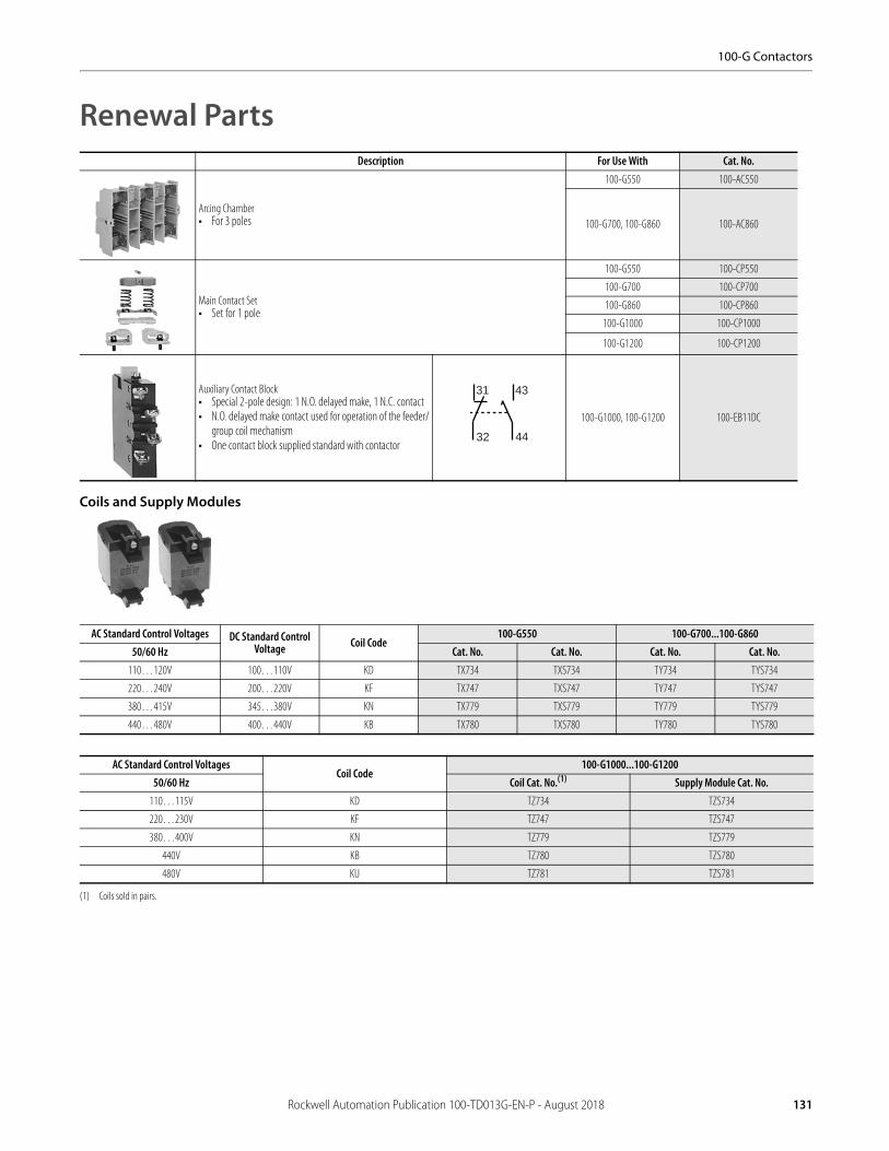
100-G Contactors
Renewal Parts
Coils and Supply Modules
Description For Use With Cat. No.
Arcing Chamber• For 3 poles
100-G550 100-AC550
100-G700, 100-G860 100-AC860
Main Contact Set• Set for 1 pole
100-G550 100-CP550
100-G700 100-CP700
100-G860 100-CP860
100-G1000 100-CP1000
100-G1200 100-CP1200
Auxiliary Contact Block• Special 2-pole design: 1 N.O. delayed make, 1 N.C. contact• N.O. delayed make contact used for operation of the feeder/
group coil mechanism• One contact block supplied standard with contactor
100-G1000, 100-G1200 100-EB11DC
AC Standard Control Voltages DC Standard Control Voltage Coil Code
100-G550 100-G700...100-G86050/60 Hz Cat. No. Cat. No. Cat. No. Cat. No.
110…120V 100…110V KD TX734 TXS734 TY734 TYS734
220…240V 200…220V KF TX747 TXS747 TY747 TYS747
380…415V 345…380V KN TX779 TXS779 TY779 TYS779
440…480V 400…440V KB TX780 TXS780 TY780 TYS780
AC Standard Control VoltagesCoil Code
100-G1000...100-G120050/60 Hz Coil Cat. No.(1)
(1) Coils sold in pairs.
Supply Module Cat. No.110…115V KD TZ734 TZS734
220…230V KF TZ747 TZS747
380…400V KN TZ779 TZS779
440V KB TZ780 TZS780
480V KU TZ781 TZS781
31
32
43
44
Rockwell Automation Publication 100-TD013G-EN-P - August 2018 131

100-G Contactors
SpecificationsElectrical Data
100-G550 100-G700 100-G860 100-G1000 100-G1200AC-1,Three-phase Switching-IEC
Ambient temperature: 40 °C
Ie
≤690V [A] 760 1000 1100 1200 1350
≤230V [kW] 303 398 438 478 538
≤240V [kW] 316 416 457 499 561
≤400V [kW] 527 693 762 831 935
≤415V [kW] 546 719 791 863 970
≤500V [kW] 658 866 953 1039 1169
≤690V [kW] 908 1195 1315 1434 1613
Ambient temperature: 60 °C
Ie
≤690V [A] 605 800 870 960 1,085
≤230V [kW] 241 319 347 382 432
≤240V [kW] 251 333 362 399 451
≤400V [kW] 419 554 603 665 752
≤415V [kW] 435 575 625 690 780
≤500V [kW] 524 693 753 831 940
≤690V [kW] 723 956 1040 1147 1297
Continuous Current- UL/CSA General Purpose Rating 40 °C [A] 520 700 810 — 1215
Switching of 3-phase Motors-IECAC-2,AC-3 230/240V [A] 550 700 860 1000 1200
50Hz/60°C
400/415V [A] 550 700 860 1000 1200
500V [A] 550 700 860 1000 1200
690V [A] 500 630 700 860 1000
230V [kW] 179 228 280 326 391
240V [kW] 187 238 293 340 408
400V [kW] 312 414 509 592 710
415V [kW] 324 430 528 628 737
500V [kW] 407 518 636 756 888
690V [kW] 510 657 730 897 1043
AC-4 at 200 000 operations
50Hz
230/240V [A] 140 180 210 260 300
400/415V [A] 140 180 210 260 300
230V [kW] 45 57 67 83 97
240V [kW] 47 60 70 87 101
400V [kW] 78 101 118 146 170
415V [kW] 81 105 122 151 176
AC-4, Squirrel-cage motors with reversing and jogging at 20,000 (25,000),operations230/240V [A] 360 430 520 (630) (700)
400/415V(1)
(1) At rated Voltage 415V and rated current: Lifespan -25%.
[A] 350 420 520 (630) (700)
230V [kW] 116 139 170 (205) (228)
240V [kW] 120 151 177 (214) (245)
400V [kW] 198 238 295 (357) (414)
415V [kW] 206 247 300 (359) (424)
132 Rockwell Automation Publication 100-TD013G-EN-P - August 2018

100-G Contactors
100-G550 100-G700 100-G860 100-G1000 100-G1200Switching of 3-phase Motors-UL/CSA
60Hz/60°C
200V [A] 414 552 692 — 1185
230V [A] 360 602 722 — 1130
460V [A] 414 590 708 — 1062
575V [A] 336 472 576 — 864
200V [Hp] 150 200 250 — 450
230V [Hp] 150 250 300 — 450
460V [Hp] 350 500 600 — 900
575V [Hp] 350 500 600 — 900
Rated making capacity
AC-3 Ie
≤415V [A] 5500 7000 8600 10000 12000
≤500V [A] 5500 7000 8600 10000 12000
≤690V [A] 5500 7000 8600 10000 12000
Rated making capacity
AC-3 Ie
≤240V [A] 4400 5600 6900 8000 9600
≤400V [A] 4400 5600 6900 8000 9600
≤415V [A] 4400 5600 6900 8000 9600
≤500V [A] 4400 5600 6900 8000 9600
≤690V [A] 4000 5100 5600 6900 8000
Star-Delta Starting
50 Hz
230V [A] 953 1212 1490 1732 2078
240V [A] 953 1212 1490 1732 2078
400V [A] 953 1212 1490 1732 2078
415V [A] 953 1212 1490 1732 2078
500V [A] 953 1212 1490 1732 2078
690V [A] 831 1091 1195 1490 1732
230V [kW] 310 395 485 565 677
240V [kW] 324 412 507 589 707
400V [kW] 540 717 882 1025 1250
415V [kW] 561 745 915 1088 1278
500V [kW] 705 897 1102 1309 1538
690V [kW] 883 1138 1247 1554 2078
Wye-Delta Starting
60 Hz
230V [Hp] 250 400 500 650 750
460V [Hp] 600 800 1000 1300 1500
575V [Hp] 600 800 1000 1500 1500
Short-circuit Protection of Contactors without Overload Relay
Fuse gG (aM) Type 1 coordination (per IEC 60947-4-1)
500V [A] (630) 800 1000 1000 1250
690V [A] (630) 800 1000 1000 1000
Switching of Three-phase Capacitor Inductivity of dispatching between parallel switched capacitor: min. 6 pH
Single capacitors — 40 ° C
230V [kVar] 180 220 250 290 330
240V [kVar] 200 250 300 325 360
400V [kVar] 320 400 450 500 575
415V [kVar] 350 430 500 550 630
500V [kVar] 450 520 600 660 750
690V [kVar] 580 700 800 875 1000
Rockwell Automation Publication 100-TD013G-EN-P - August 2018 133
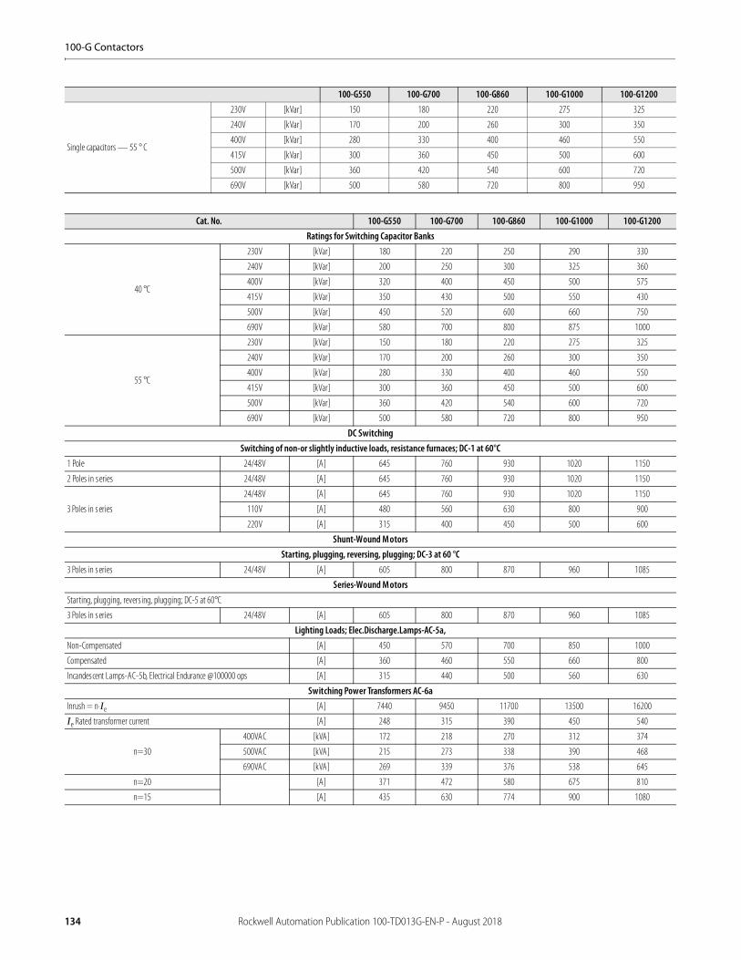
100-G Contactors
Single capacitors — 55 ° C
230V [kVar] 150 180 220 275 325
240V [kVar] 170 200 260 300 350
400V [kVar] 280 330 400 460 550
415V [kVar] 300 360 450 500 600
500V [kVar] 360 420 540 600 720
690V [kVar] 500 580 720 800 950
Cat. No. 100-G550 100-G700 100-G860 100-G1000 100-G1200Ratings for Switching Capacitor Banks
40 °C
230V [kVar] 180 220 250 290 330
240V [kVar] 200 250 300 325 360
400V [kVar] 320 400 450 500 575
415V [kVar] 350 430 500 550 430
500V [kVar] 450 520 600 660 750
690V [kVar] 580 700 800 875 1000
55 °C
230V [kVar] 150 180 220 275 325
240V [kVar] 170 200 260 300 350
400V [kVar] 280 330 400 460 550
415V [kVar] 300 360 450 500 600
500V [kVar] 360 420 540 600 720
690V [kVar] 500 580 720 800 950
DC SwitchingSwitching of non-or slightly inductive loads, resistance furnaces; DC-1 at 60°C
1 Pole 24/48V [A] 645 760 930 1020 1150
2 Poles in series 24/48V [A] 645 760 930 1020 1150
3 Poles in series
24/48V [A] 645 760 930 1020 1150
110V [A] 480 560 630 800 900
220V [A] 315 400 450 500 600
Shunt-Wound MotorsStarting, plugging, reversing, plugging; DC-3 at 60 °C
3 Poles in series 24/48V [A] 605 800 870 960 1085
Series-Wound MotorsStarting, plugging, revers ing, plugging; DC-5 at 60°C
3 Poles in series 24/48V [A] 605 800 870 960 1085
Lighting Loads; Elec.Discharge.Lamps-AC-5a,Non-Compensated [A] 450 570 700 850 1000
Compensated [A] 360 460 550 660 800
Incandescent Lamps-AC-5b, Electrical Endurance @100000 ops [A] 315 440 500 560 630
Switching Power Transformers AC-6aInrush = n·Ie [A] 7440 9450 11700 13500 16200
Ie Rated transformer current [A] 248 315 390 450 540
n=30
400VAC [kVA] 172 218 270 312 374
500VAC [kVA] 215 273 338 390 468
690VAC [kVA] 269 339 376 538 645
n=20 [A] 371 472 580 675 810
n=15 [A] 435 630 774 900 1080
100-G550 100-G700 100-G860 100-G1000 100-G1200
134 Rockwell Automation Publication 100-TD013G-EN-P - August 2018

100-G Contactors
Mechanical Data
Rated Short-Time Withstand, ICW, 60 °C
1s [A] 5500 7000 8000 10000 12000
4s [A] 5500 7000 8000 10000 12000
10s [A] 4400 5600 6900 8000 9600
15s [A] 3800 5000 6000 7400 8500
60s [A] 2300 2800 3400 4000 4800
240s [A] 1300 1800 2000 2300 2700
900s [A] 850 1150 1350 1600 1900
Minimum cooling time at zero current [Min.] 60 60 60 60 60
Resistance and Energy DissipationMain circuit resis tance [m] 0.11 0.1 0.08 0.06 0.05
Total energy dissipation at Ie AC-3 [W] 99 147 177 180 216
Excess energy dissipation at Ie AC-3AC Control [W] 110 172 202 250 286
DC Control [W] 109 169 199 240 276
Cat. No. 100-G550 100-G700 100-G860 100-G1000 100-G1200
Mechanical LifeAC Control [Million operations] 5 5 5 1 1
DC Control [Million operations] 5 5 5 1 1
Shipping Weights
AC Control[kg] 13.8 26.4 28.4 50.3 53.4
[lb] 30.4 58.1 62.5 110.8 117.6
DC Control[kg] 13.8 26.4 28.4 50.3 53.4
[lb] 30.4 58.1 62.5 110.8 117.6
TerminalsTerminal Dimensions [mm] 6 x 40 8 x 50 8 x 50 10 x 50 10 x 60
Terminal screw hole s ize [mm] (1) x 13 (1) x 13 (1) x 15 (2) x 13 (2) x 13
Terminations-Power Type Hexagonal Bolt
Direct Connectionb max. [mm] 50 60 60 60 60
c max. [mm] 20 20 25 25 25
s max. [mm] 2x5 2x5 2x6 2x6 2x8
min. [mm] 12.5 13 15 2x13 2x13
Recommended Torque[N•m] 50 60 75 60 60
[ft.-lb] 37 44 55 44 44
Conductor/Wire Terminations Busbar (Width) [mm] 40 50 50 50 60
Hex screw [in] 1/2 3/8 3/8 3/8 3/8
Recommended Torque[N•m] 42 62 62 56 56
[lb•in] 375 550 550 500 500
Auxiliary Contact [mm2] (2) x 2.5 (2) x 2.5 (2) x 2.5 (2) x 2.5 (2) x 2.5
Coils [mm2] (2) x 2.5 (2) x 2.5 (2) x 2.5 (2) x 2.5 (2) x 2.5
Cat. No. 100-G550 100-G700 100-G860 100-G1000 100-G1200
Rockwell Automation Publication 100-TD013G-EN-P - August 2018 135

100-G Contactors
Coil Data
Auxiliary Contacts
General
Standards Compliance and Certifications
Cat. No. 100-G550 100-G700 100-G860
100-G1000
100-G1200
Operating Limits
AC-50 Hz
Pick-up [x Us] 0.85…1.1
Drop-out [x Us] 0.2…0.5 0.2…0.75 0.1…0.6
AC-60 Hz
Pick-up [x Us] 0.85…1.1
Drop-out [x Us] 0.2…0.5 0.2…0.75 0.1…0.6
DC Control
Pick-up [x Us] 0.85…1.1
Drop-out [x Us] 0.2…0.5 0.2…0.75 0.1…0.6
Pickup and Holding Power
AC-50 Hz
Pick-up [VA] 800…950 1350…1600 2400
Hold-in [VA] 9…11 21…25 70
AC-60 Hz
Pick-up [VA] 800…950 1350…1600 2400
Hold-in [VA] 9…11 21…25 70
DC Control
Pick-up [W] 700…850 1300…1550 2100
Hold-in [W] 8…10 18…22 60
Operating Times: Switching Delay
AC
Making delay [ms] 50…100 50…100
Breaking delay [ms] 20…50(1)/150…200/
500…1000(2)
(1) Accelerates(2) Delays
25…50
DC
Making delay [ms] 50…100 50…100
Breaking delay [ms] 20…50(1)/150…200/
500…1000(2) 25…50
Cat. No. 100-G550
100-G700
100-G860
100-G1000
100-G1200
Switching of AC Loads
AC-1 Ithat 40 °C [A] 16 16
at 60 °C [A] 12 12
AC-15 at rated voltage
120V [A] 6 6
230V [A] 3 3
240V [A] 3 3
400V [A] 2 2
415V [A] 2 2
500V [A] 1.5 1.5
690V [A] 1 1
Switching of DC Loads
DC-13 control of electromagnets
2V DC [A] 6 6
48V DC [A] 3 3
110V DC [A] 1 1
220V DC [A] 0.5 0.5
Back-up Fuse Short-circuit protection without contact welding per IEC60947-5Fuse gG [A] 10 16
Cat. No. 100-G550 100-G700 100-G860 100-G1000
100-G1200
Rated Isolation Voltage Ui
IEC, AS, BS, SEV, VDE, 0660 [V] 1,000 690
UL,CSA [V] 600 600
Rated Impulse Voltage Withstand Uimp
1minuteperIEC947-4 [KV] 8 2,5
Rated Voltage-Main Control Ue
AC, 50/60Hz [V] 230, 240, 400, 415, 460, 500, 575, 690V
230, 240, 400, 415, 460, 500, 575, 690V
DC 24, 48, 110, 220, 440V
Operating Frequency for AC Loads, 50/60 Hz [Hz] 180/hr. for 0.25 s start time-42/hr. for 1s start time
Insulation Class of the Magnetic Coil Class B per VDE 0660, table 22
Rated frequency of the Coil AC 50/60 Hz, DC
Ambient Temperature
Storage -40 °C…+ 80 °C
Operation at rated current -25 °C…70 °C
Climatic Withstand Damp alternating conditions cyclical, per DIN 50016 and 40046, part 38, IEC 60068
Altitude 2000 m above sea level, per IEC60947-1
Type of Protection IP00 IEC 60529/DIN 40050
Standards Compliance Certifications
EN/IEC 60947-4-1 CE Marked
IEC 60947 Type “1” Coordination cULus Listed (File No. E 3125, Guide NLDX, NLDX7)CSA C22.2 No. 14
UL 508
136 Rockwell Automation Publication 100-TD013G-EN-P - August 2018

100-G Contactors
Life-Load Curves
100-G550…100-G1200
Figure 35 - AC-3 Switching of Running Three-phase Motors, Ue = 380…460V AC; AC-1 Non or Slightly Inductive Loads, Resistance Furnaces
Rockwell Automation Publication 100-TD013G-EN-P - August 2018 137
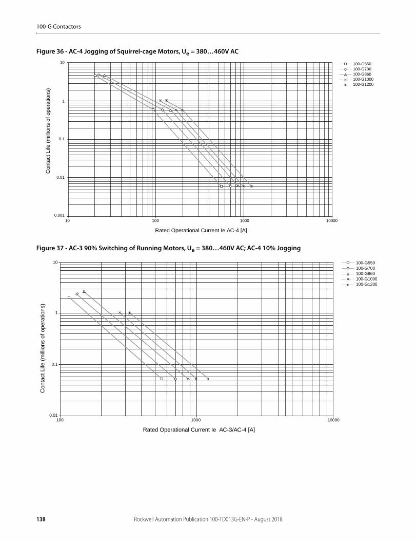
100-G Contactors
Figure 36 - AC-4 Jogging of Squirrel-cage Motors, Ue = 380…460V AC
Figure 37 - AC-3 90% Switching of Running Motors, Ue = 380…460V AC; AC-4 10% Jogging
100-G550100-G700100-G860100-G1000100-G1200
10
1
0.1
10
Con
tact
Life
(m
illio
ns o
f ope
ratio
ns)
1000 10000
Rated Operational Current Ie AC-4 [A]
0.01
0.001100
100-G550100-G700100-G860100-G1000100-G1200
10
1
0.1
100
Con
tact
Life
(m
illio
ns o
f ope
ratio
ns)
1000 10000
Rated Operational Current Ie AC-3/AC-4 [A]
0.01
138 Rockwell Automation Publication 100-TD013G-EN-P - August 2018
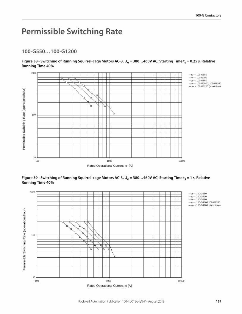
100-G Contactors
Permissible Switching Rate
100-G550…100-G1200
Figure 38 - Switching of Running Squirrel-cage Motors AC-3, Ue = 380…460V AC; Starting Time ts = 0.25 s, Relative Running Time 40%
Figure 39 - Switching of Running Squirrel-cage Motors AC-3, Ue = 380…460V AC; Starting Time ts = 1 s, Relative Running Time 40%
100-G550100-G700100-G860100-G1000, 100-G1200100-G1200 (short time)
1000
100
100
Per
mis
sibl
e S
witc
hing
Rat
e (o
pera
tions
/hou
r)
1000 10000
Rated Operational Current Ie [A]
10
100-G550100-G700100-G860100-G1000,100-G1200100-G1200 (short-time)
1000
100
10
100
Per
mis
sibl
e S
witc
hing
Rat
e (o
pera
tions
/hou
r)
1000 10000
Rated Operational Current Ie [A]
Rockwell Automation Publication 100-TD013G-EN-P - August 2018 139
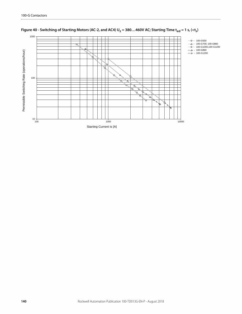
100-G Contactors
Figure 40 - Switching of Starting Motors (AC-2, and AC4) Uz = 380…460V AC; Starting Time ted = 1 s, (<ts)
100-G550100-G700; 100-G860100-G1000,100-G1200100-G860100-G1200
1000
100
10100
Per
mis
sibl
e S
witc
hing
Rat
e (o
pera
tions
/hou
r)
1000 10000
Starting Current Is [A]
140 Rockwell Automation Publication 100-TD013G-EN-P - August 2018
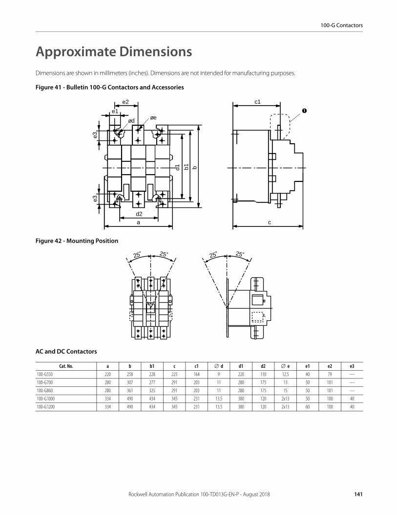
100-G Contactors
Approximate DimensionsDimensions are shown in millimeters (inches). Dimensions are not intended for manufacturing purposes.
Figure 41 - Bulletin 100-G Contactors and Accessories
Figure 42 - Mounting Position
AC and DC Contactors
Cat. No. a b b1 c c1 d d1 d2 e e1 e2 e3100-G550 220 258 228 225 164 9 220 110 12.5 40 79 —
100-G700 280 307 277 291 203 11 280 175 13 50 101 —
100-G860 280 361 325 291 203 11 280 175 15 50 101 —
100-G1000 334 490 434 345 231 13.5 380 120 2x13 50 100 40
100-G1200 334 490 434 345 231 13.5 380 120 2x13 60 100 40
d2a
d1 b1 b
c
e1
e2 c1
øeød
e3e3
➊
25˚ 25˚ 25˚ 25˚
Rockwell Automation Publication 100-TD013G-EN-P - August 2018 141

100-G Contactors
Contactors with Accessories
Contactor with mmAuxiliary contact block a
Mechanical Interlock
side by side
100-G550/100-G550 a+42+a
100-G700, -860/100-G700, -860 a+32+a
100-G1000, -1200/100-G1000, -1200 a+46+a
100-G550/100-G700, -860 a+37+a
100-G700, -860/100-G1000, -1200 a+73+a
stacked vertically
100-G550/100-G550 b+56 + b
100-G700, -860/100-G700, -860 b/2+380…480+b/2
100-G1000, -1200/100-G1000, -1200 b+120…170+b
100-G550/100-G700, -860 b/2+400+b/2
100-G700, -860/100-G1000, -1200 b/2+570+b/2
4th add-on neutral switching pole
100-G550 a+74
100-G700, -860 a+68
100-G1000, -1200 a+76
Mechanical latch
100-G550 b+59
100-G700 b+64
100-G860 b+37
142 Rockwell Automation Publication 100-TD013G-EN-P - August 2018

IEC Contactor Specifications
Rockwell Automation Publication 100-TD013G-EN-P - August 2018 143
Allen-Bradley, Rockwell Automation, and LISTEN. THINK. SOLVE are trademarks of Rockwell Automation, Inc.Trademarks not belonging to Rockwell Automation are property of their respective companies.
Publication 100-TD013G-EN-P - August 2018
Rockwell Automation SupportUse the following resources to access support information.
Documentation FeedbackYour comments will help us serve your documentation needs better. If you have any suggestions on how to improve this document, complete the How Are We Doing? form at http://literature.rockwellautomation.com/idc/groups/literature/documents/du/ra-du002_-en-e.pdf.
Technical Support Center Knowledgebase Articles, How-to Videos, FAQs, Chat, User Forums, and Product Notification Updates. www.rockwellautomation.com/knowledgebase
Local Technical Support Phone Numbers Locate the phone number for your country. www.rockwellautomation.com/global/support/get-support-now.page
Direct Dial CodesFind the Direct Dial Code for your product. Use the code to route your call directly to a technical support engineer.
www.rockwellautomation.com/global/support/direct-dial.page
Literature Library Installation Instructions, Manuals, Brochures, and Technical Data. www.rockwellautomation.com/literature
Product Compatibility and Download Center (PCDC)
Get help determining how products interact, check features and capabilities, and find associated firmware.
www.rockwellautomation.com/global/support/pcdc.page
Rockwell Otomasyon Ticaret A.Ş., Kar Plaza İş Merkezi E Blok Kat:6 34752 İçerenköy, İstanbul, Tel: +90 (216) 5698400
Rockwell Automation maintains current product environmental information on its website at http://www.rockwellautomation.com/rockwellautomation/about-us/sustainability-ethics/product-environmental-compliance.page.
Supersedes Publication 100-TD013F-EN-P - November 2017 Copyright © 2018 Rockwell Automation, Inc. All rights reserved. Printed in the U.S.A.
Related Documents