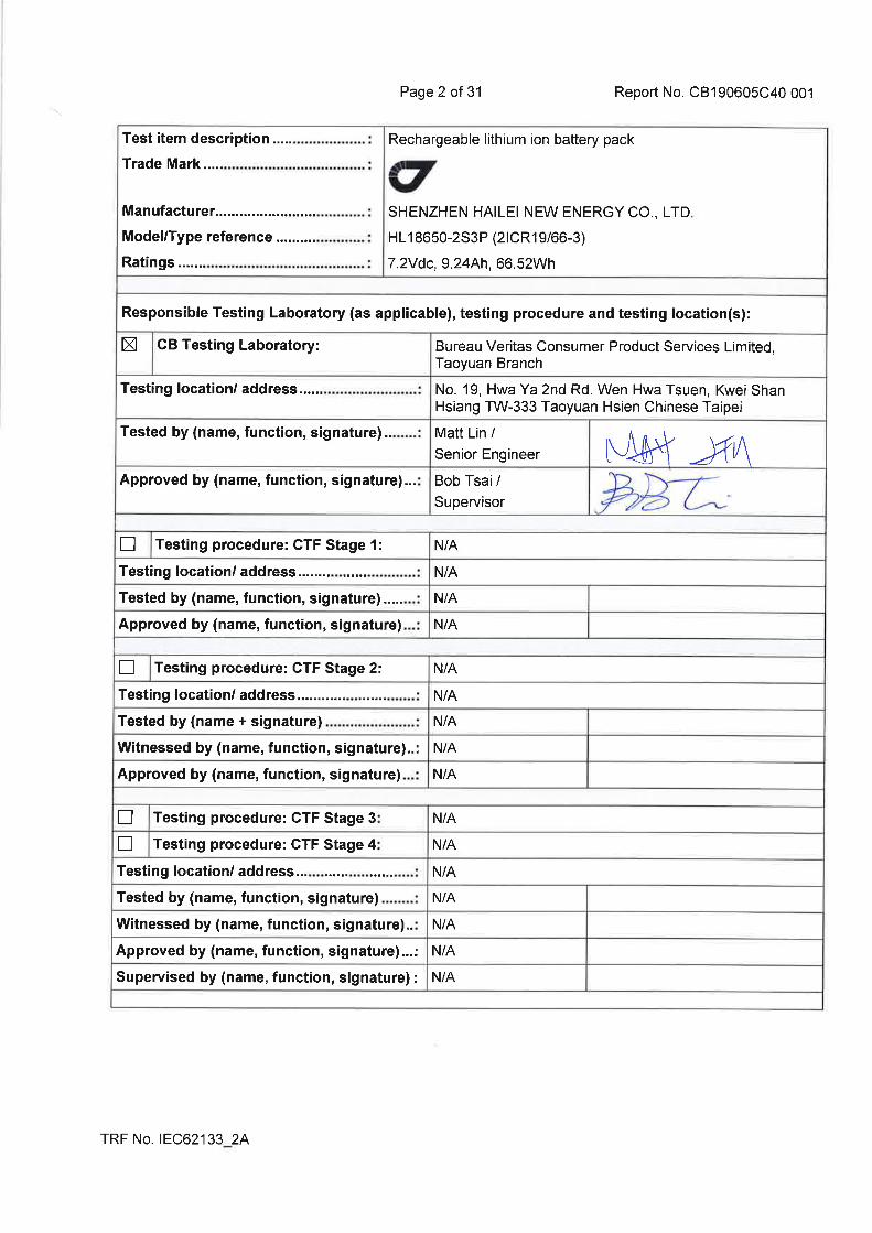
Ref. Certif. No. FR_706574 LCIE – Laboratoire Central des Industries Electriques 33, avenue du Général Leclerc – BP8 FR 92 266 Fontenay aux Roses Cedex www.lcie.fr Date: 12/08/2019 Signature: Julien Gauthier Certification Officer 1/1 IEC SYSTEM FOR MUTUAL RECOGNITION OF TEST CERTIFICATES FOR ELECTRICAL EQUIPMENT (IECEE) CB SCHEME CB TEST CERTIFICATE Product Rechargeable Lithium-Ion Battery Pack Name and address of the applicant JAVAD GNSS, Inc. 900 Rock Avenue, San Jose, CA, 95131 - USA Name and address of the manufacturer SHENZHEN HAILEI NEW ENERGY CO., LTD. No. 69 Lijing South Road, Shijing Street, Pingshan District, Shenzhen - CHINA Name and address of the factory SHENZHEN HAILEI NEW ENERGY CO., LTD. No. 69 Lijing South Road, Shijing Street, Pingshan District, Shenzhen - CHINA Note: When more than one factory, please report on page 2 Additional Information on page 2 Ratings and principal characteristics 7.2Vdc, 9.24Ah, 66.52Wh Trademark (if any) Customer’s Testing Facility (CTF) Stage used / Model / Type Ref. HL18650-2S3P (2ICR19/66-3) Additional information (if necessary may also be reported on page 2) Additional Information on page 2 A sample of the product was tested and found to be in conformity with IEC 62133-2:2017 As shown in the Test Report Ref. No. which forms part of this Certificate CB190605C40 001 This CB Test Certificate is issued by the National Certification Body

Welcome message from author
This document is posted to help you gain knowledge. Please leave a comment to let me know what you think about it! Share it to your friends and learn new things together.
Transcript

Ref. Certif. No.
FR_706574
LCIE – Laboratoire Central des Industries Electriques 33, avenue du Général Leclerc – BP8 FR 92 266 Fontenay aux Roses Cedex www.lcie.fr
Date: 12/08/2019
Signature: Julien Gauthier Certification Officer
1/1
IEC SYSTEM FOR MUTUAL RECOGNITION OF TEST CERTIFICATES FOR ELECTRICAL EQUIPMENT (IECEE) CB SCHEME
CB TEST CERTIFICATE
Product
Rechargeable Lithium-Ion Battery Pack
Name and address of the applicant JAVAD GNSS, Inc. 900 Rock Avenue, San Jose, CA, 95131 - USA
Name and address of the manufacturer
SHENZHEN HAILEI NEW ENERGY CO., LTD. No. 69 Lijing South Road, Shijing Street, Pingshan District, Shenzhen - CHINA
Name and address of the factory
SHENZHEN HAILEI NEW ENERGY CO., LTD. No. 69 Lijing South Road, Shijing Street, Pingshan District, Shenzhen - CHINA
Note: When more than one factory, please report on page 2
Additional Information on page 2
Ratings and principal characteristics
7.2Vdc, 9.24Ah, 66.52Wh
Trademark (if any)
Customer’s Testing Facility (CTF) Stage used
/
Model / Type Ref.
HL18650-2S3P (2ICR19/66-3)
Additional information (if necessary may also be reported on page 2)
Additional Information on page 2
A sample of the product was tested and found to be in conformity with
IEC 62133-2:2017
As shown in the Test Report Ref. No. which forms part of this Certificate
CB190605C40 001
This CB Test Certificate is issued by the National Certification Body

Test Report issued under the responsibility of:
TEST REPORT IEC 62133-2
Secondary cells and batteries containing alkaline or other non-acid electrolytes – Safety requirements for portable sealed secondary cells, and for batteries made
from them, for use in portable applications – Part 2: Lithium systems
Report Number. .............................. : CB190605C40 001
Date of issue ................................... : 2019-07-24
Total number of pages ................... : 31
Name of Testing Laboratory preparing the Report ...................... :
Bureau Veritas Consumer Product Services Limited, Taoyuan Branch
Applicant’s name ............................ : JAVAD GNSS, Inc.
Address ........................................... : USA, 900 Rock Avenue, San Jose, CA, 95131
Test specification:
Standard .......................................... : IEC 62133-2:2017
Test procedure................................ : CB Scheme
Non-standard test method ............. : N/A
Test Report Form No. ..................... : IEC62133_2A
Test Report Form(s) Originator ..... : DEKRA
Master TRF ...................................... : Dated 2017-08-10
Copyright © 2017 IEC System of Conformity Assessment Schemes for Electrotechnical Equipment and Components (IECEE System). All rights reserved.
This publication may be reproduced in whole or in part for non-commercial purposes as long as the IECEE is acknowledged as copyright owner and source of the material. IECEE takes no responsibility for and will not assume liability for damages resulting from the reader's interpretation of the reproduced material due to its placement and context.
If this Test Report Form is used by non-IECEE members, the IECEE/IEC logo and the reference to the CB Scheme procedure shall be removed.
This report is not valid as a CB Test Report unless signed by an approved CB Testing Laboratory and appended to a CB Test Certificate issued by an NCB in accordance with IECEE 02.
General disclaimer:
The test results presented in this report relate only to the object tested. This report shall not be reproduced, except in full, without the written approval of the Issuing CB Testing Laboratory. The authenticity of this Test Report and its contents can be verified by contacting the NCB, responsible for this Test Report.

Page 3 of 31 Report No. CB190605C40 001
TRF No. IEC62133_2A
List of Attachments (including a total number of pages in each attachment):
N/A
Summary of testing:
Tests performed (name of test and test clause):
5.2 Insulation and wiring
5.3 Venting
5.4 Temperature/voltage/current management
5.5 Terminal contacts
5.6 Assembly of cells into batteries
5.7 Quality plan
7.3.2 External short-circuit (battery)
7.3.3 Free fall (battery)
7.3.6 Over-charging of battery (battery)
7.3.8.1 Vibration (batteries)
7.3.8.2 Shock (batteries)
The load conditions used during testing:
The unit is charging the empty battery pack and discharging the full charged battery pack according to its rating.
Note:
(1) Unless otherwise stated, the charging procedure for test purposes is carried out in
an ambient temperature of 20±5C, using the method declared by the manufacturer.
(2) Prior to charging, the battery cell and battery
pack shall have been discharged at 20±5C at a constant current of 0.2 It A down to a specified final voltage.
Testing location:
Bureau Veritas Consumer Product Services Limited, Taoyuan Branch
No. 19, Hwa Ya 2nd Rd. Wen Hwa Tsuen, Kwei Shan Hsiang TW-333 Taoyuan Hsien Chinese Taipei
Summary of compliance with National Differences
List of countries addressed:
DK (DK=Denmark), HU (HU=Hungary), SE (SE=Sweden)
The product fulfils the requirements of IEC 62133-2: 2017 and EN 62133-2:2017

Page 4 of 31 Report No. CB190605C40 001
TRF No. IEC62133_2A
Copy of marking plate:
The artwork below may be only a draft. The use of certification marks on a product must be authorized by the respective NCBs that own these marks.
Explanation of date Code:

Page 5 of 31 Report No. CB190605C40 001
TRF No. IEC62133_2A
Test item particulars...................................................:
Classification of installation and use.......................: Built-in
Supply Connection .....................................................: Customized connector
Recommend charging method declared by the manufacturer ...............................................................:
Keep 1.83A charge current in CC (constant current) mode until battery pack voltage reaches 8.40V charge for 0.02C (Cut off)
Discharge current (0,2 It A) .......................................: 1.848A
Specified final voltage ................................................: End of charge 8.40V, End of discharge 5.0V
Upper limit charging voltage per cell .......................: 4.20V
Maximum charging current .......................................: 4.5A
Charging temperature upper limit ............................: 45oC
Charging temperature lower limit .............................: 10oC
Polymer cell electrolyte type .....................................: gel polymer solid polymer N/A
Possible test case verdicts:
- test case does not apply to the test object ........... : N/A
- test object does meet the requirement .................. : P (Pass)
- test object does not meet the requirement ........... : F (Fail)
Testing .......................................................................... :
Date of receipt of test item ........................................ : 2019-06-05
Date (s) of performance of tests ............................... : 2019-06-08 to 2019-06-26
General remarks:
"(See Enclosure #)" refers to additional information appended to the report. "(See appended table)" refers to a table appended to the report. Throughout this report a comma / point is used as the decimal separator.
Manufacturer’s Declaration per sub-clause 4.2.5 of IECEE 02:
The application for obtaining a CB Test Certificate includes more than one factory location and a declaration from the Manufacturer stating that the sample(s) submitted for evaluation is (are) representative of the products from each factory has been provided ............................................................... :
Yes
Not applicable
When differences exist; they shall be identified in the General product information section.
Name and address of factory (ies) .......................... : SHENZHEN HAILEI NEW ENERGY CO., LTD.
No. 69 Lijing South Road, Shijing Street, Pingshan District, Shenzhen

Page 6 of 31 Report No. CB190605C40 001
TRF No. IEC62133_2A
General product information:
(1) The equipment is a Rechargeable lithium ion battery pack with 2 series 3 parallel lithium ion rechargeable battery cell.
(2) The maximum ambient temperature of EUT is specified as 45C for Charging and 60C for Discharging.
(3) Dimension of EUT: (T) 19.50 mm by (W) 114.00 mm by (H) 67.00 mm max.
(4) Weight: approx. 296.27 g.
Conditions of acceptability: The product is a built-in type “Rechargeable lithium ion battery pack” without external physical moulded case, the compliance of clause “7.2.2 Moulded case stress at high ambient temperature (battery)“ shall be evaluated during the final assembly.
Test condition:
Temperature: 20±5C Relative humidity: 60% Air pressure: 950 mbar The test samples were pre-production samples without serial number.

Page 7 of 31 Report No. CB190605C40 001
IEC 62133-2
Clause Requirement + Test Result - Remark Verdict
TRF No. IEC62133_2A
4 PARAMETER MEASUREMENT TOLERANCES P
Parameter measurement tolerances Both normal and foreseeable misuses are evaluated in the report. All control and measure values were within the tolerances.
P
5 GENERAL SAFETY CONSIDERATIONS P
5.1 General See below. P
Cells and batteries so designed and constructed that they are safe under conditions of both intended use and reasonably foreseeable misuse
The battery is safe and do not present significant hazards under the condition of reasonably foreseeable misuse.
P
5.2 Insulation and wiring See below. P
The insulation resistance between the positive terminal and externally exposed metal surfaces of the battery (excluding electrical contact surfaces) is not less than 5 MΩ
The battery pack is built-in type, no externally exposed metal surfaces of the battery (excluding electrical contact surfaces).
N/A
Insulation resistance (MΩ) ...................................... : -- —
Internal wiring and insulation are sufficient to withstand maximum anticipated current, voltage and temperature requirements
Internal wiring and insulation are used within their ratings and are checked for correct application.
P
Orientation of wiring maintains adequate clearance and creepage distances between conductors
The cell was spot welding with PCB via Nickel sheet.
P
Mechanical integrity of internal connections accommodates reasonably foreseeable misuse
The cell was spot welding with PCB via Nickel sheet.
P
5.3 Venting See below. P
Battery cases and cells incorporate a pressure relief mechanism or are constructed so that they relieve excessive internal pressure at a value and rate that will preclude rupture, explosion and self-ignition
The edge of packing which next to the terminals was considered as the pressure relief mechanism, which can release the pressure during the abnormal operation.
P
Encapsulation used to support cells within an outer casing does not cause the battery to overheat during normal operation nor inhibit pressure relief
The EUT is built-in type, no such outer case used. It shall be evaluated in the final assembly.
N/A
5.4 Temperature, voltage and current management See below. P
Batteries are designed such that abnormal temperature rise conditions are prevented
Temperature limiter and protective IC used.
P
Batteries are designed to be within temperature, voltage and current limits specified by the cell manufacturer
Current limiter and protective IC used.
P

Page 8 of 31 Report No. CB190605C40 001
IEC 62133-2
Clause Requirement + Test Result - Remark Verdict
TRF No. IEC62133_2A
Batteries are provided with specifications and charging instructions for equipment manufacturers so that specified chargers are designed to maintain charging within the temperature, voltage and current limits specified
The battery vender had provided specifications including charge instruction for equipment manufacture reference.
P
5.5 Terminal contacts See below. P
The size and shape of the terminal contacts ensure that they can carry the maximum anticipated current
The cross section areas of wires were considered enough to carry the rating current of the battery.
N/A
External terminal contact surfaces are formed from conductive materials with good mechanical strength and corrosion resistance
The connector provides good mechanical strength to the copper alloy terminal.
P
Terminal contacts are arranged to minimize the risk of short-circuit
The distance between the terminals is considered enough to minimize the possibility of short circuits.
P
5.6 Assembly of cells into batteries The distance between the terminals is considered enough to minimize the possibility of short circuits.
P
5.6.1 General See below. P
Each battery have an independent control and protection for current, voltage, temperature and any other parameter required for safety and to maintain the cells within their operating region
The battery pack with protective independent control and protection provided.
P
This protection may be provided external to the battery such as within the charger or the end devices
The battery pack with protective independent control and protection provided.
N/A
If protection is external to the battery, the manufacturer of the battery provide this safety relevant information to the external device manufacturer for implementation
The battery pack with protective independent control and protection provided.
N/A
If there is more than one battery housed in a single battery case, each battery have protective circuitry that can maintain the cells within their operating regions
The EUT is built-in type and provide single battery module which assembly by 6 same cells and protect by independent protective circuit.
N/A
Manufacturers of cells specify current, voltage and temperature limits so that the battery manufacturer/designer may ensure proper design and assembly
Cell vender provided cell spec including current, voltage and temperature limitation.
P
Batteries that are designed for the selective discharge of a portion of their series connected cells incorporate circuitry to prevent operation of cells outside the limits specified by the cell manufacturer
The EUT has no design for selective discharge.
N/A
Protective circuit components added as appropriate and consideration given to the end-device application
The EUT protective circuits were consideration end device application.
P
Page 9 of 31 Report No. CB190605C40 001
IEC 62133-2
Clause Requirement + Test Result - Remark Verdict
TRF No. IEC62133_2A
The manufacturer of the battery provide a safety analysis of the battery safety circuitry with a test report including a fault analysis of the protection circuit under both charging and discharging conditions confirming the compliance
After testing the EUT was compliance and according this standard.
N/A
5.6.2 Design recommendation See below. P
For the battery consisting of a single cell or a single cellblock, it is recommended that the charging voltage of the cell does not exceed the upper limit of the charging voltage specified in Table 2
The battery pack consisting six cells (2 series - 3 parallel) and charge voltage of each single cell does not exceed 4.25Vdc according to Clause 7.1.2, Table 2.
N/A
For the battery consisting of series-connected plural single cells or series-connected plural cellblocks, it is recommended that the voltages of any one of the single cells or single cellblocks does not exceed the upper limit of the charging voltage, specified in Table 2, by monitoring the voltage of every single cell or the single cellblocks
The battery pack consisting six cells (2 series - 3 parallel) and charge voltage of each single cell does not exceed 4.25Vdc according to Clause 7.1.2, Table 2.
P
For the battery consisting of series-connected plural single cells or series-connected plural cellblocks, it is recommended that charging is stopped when the upper limit of the charging voltage is exceeded for any one of the single cells or single cellblocks by measuring the voltage of every single cell or the single cellblocks
The battery pack consisting six cells (2 series - 3 parallel) and charge voltage of each single cell does not exceed 4.25Vdc according to Clause 7.1.2, Table 2.
P
For batteries consisting of series-connected cells or cell blocks, nominal charge voltage not be counted as an overcharge protection
The battery pack consisting six cells (2 series - 3 parallel) and overcharge protection by protective IC.
P
For batteries consisting of series-connected cells or cell blocks, cells have closely matched capacities, be of the same design, be of the same chemistry and be from the same manufacturer
The battery pack assembly by six same cells.
P
It is recommended that the cells and cell blocks not discharged beyond the cell manufacturer’s specified final voltage
The battery pack protect circuit design which refer to cell spec and recommended.
P
For batteries consisting of series-connected cells or cell blocks, cell balancing circuitry incorporated into the battery management system
The EUT has no such function. N/A
5.6.3 Mechanical protection for cells and components of batteries
See below. P
Mechanical protection for cells, cell connections and control circuits within the battery provided to prevent damage as a result of intended use and reasonably foreseeable misuse
Considered. P
The mechanical protection can be provided by the battery case or it can be provided by the end product enclosure for those batteries intended for building into an end product
The EUT is built-in type battery pack.
N/A

Page 10 of 31 Report No. CB190605C40 001
IEC 62133-2
Clause Requirement + Test Result - Remark Verdict
TRF No. IEC62133_2A
The battery case and compartments housing cells designed to accommodate cell dimensional tolerances during charging and discharging as recommended by the cell manufacturer
The EUT is built-in type battery pack without physical enclosure, it should be consider with end product.
N/A
For batteries intended for building into a portable end product, testing with the battery installed within the end product considered when conducting mechanical tests
The EUT is built-in type battery pack without physical enclosure, it should be consider with end product.
N/A
5.7 Quality plan See below. P
The manufacturer prepares and implements a quality plan that defines procedures for the inspection of materials, components, cells and batteries and which covers the whole process of producing each type of cell or battery
The manufacturer’s
procedures for the inspection
of materials, components,
cells and batteries and which
covers the process of
producing each type of cell
and battery comply with the
requirement.
P
5.8 Battery safety components See below. P
According annex F Considered. P
6 TYPE TEST AND SAMPLE SIZE P
Tests are made with the number of cells or batteries specified in Table 1 using cells or batteries that are not more than six months old
The batteries and cells under
testing were less than 6
months old.
P
Coin cells with resistance ≤ 3 Ω (measured according annex D) are tested according table 1
The EUT is not coin cell. N/A
Unless otherwise specified, tests are carried out in an ambient temperature of 20 °C ± 5 °C
The testing was conducted at
the ambient range of 15.0C -
25C.
P
The safety analysis of 5.6.1 identify those components of the protection circuit that are critical for short-circuit, overcharge and overdischarge protection
Protective IC / MOSFET / Thermistor / Thermal protector used.
P
When conducting the short-circuit test, consideration given to the simulation of any single fault condition that is likely to occur in the protecting circuit that would affect the short-circuit test
Considered. P
Page 11 of 31 Report No. CB190605C40 001
IEC 62133-2
Clause Requirement + Test Result - Remark Verdict
TRF No. IEC62133_2A
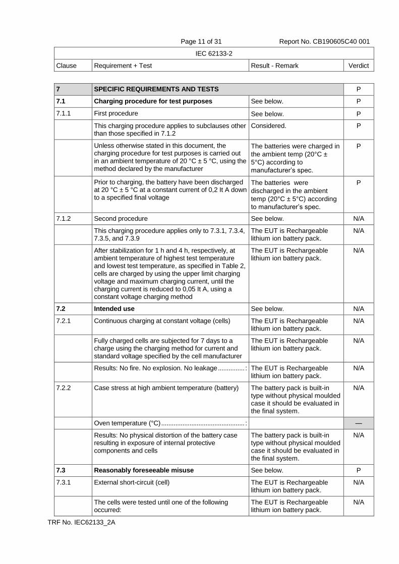
7 SPECIFIC REQUIREMENTS AND TESTS P
7.1 Charging procedure for test purposes See below. P
7.1.1 First procedure See below. P
This charging procedure applies to subclauses other than those specified in 7.1.2
Considered. P
Unless otherwise stated in this document, the charging procedure for test purposes is carried out in an ambient temperature of 20 °C ± 5 °C, using the method declared by the manufacturer
The batteries were charged in
the ambient temp (20°C ±
5°C) according to
manufacturer’s spec.
P
Prior to charging, the battery have been discharged at 20 °C ± 5 °C at a constant current of 0,2 It A down to a specified final voltage
The batteries were
discharged in the ambient
temp (20°C ± 5°C) according
to manufacturer’s spec.
P
7.1.2 Second procedure See below. N/A
This charging procedure applies only to 7.3.1, 7.3.4, 7.3.5, and 7.3.9
The EUT is Rechargeable lithium ion battery pack.
N/A
After stabilization for 1 h and 4 h, respectively, at ambient temperature of highest test temperature and lowest test temperature, as specified in Table 2, cells are charged by using the upper limit charging voltage and maximum charging current, until the charging current is reduced to 0,05 It A, using a constant voltage charging method
The EUT is Rechargeable lithium ion battery pack.
N/A
7.2 Intended use See below. N/A
7.2.1 Continuous charging at constant voltage (cells) The EUT is Rechargeable lithium ion battery pack.
N/A
Fully charged cells are subjected for 7 days to a charge using the charging method for current and standard voltage specified by the cell manufacturer
The EUT is Rechargeable lithium ion battery pack.
N/A
Results: No fire. No explosion. No leakage ............... : The EUT is Rechargeable lithium ion battery pack.
N/A
7.2.2 Case stress at high ambient temperature (battery) The battery pack is built-in type without physical moulded case it should be evaluated in the final system.
N/A
Oven temperature (°C) ............................................... : —
Results: No physical distortion of the battery case resulting in exposure of internal protective components and cells
The battery pack is built-in type without physical moulded case it should be evaluated in the final system.
N/A
7.3 Reasonably foreseeable misuse See below. P
7.3.1 External short-circuit (cell) The EUT is Rechargeable lithium ion battery pack.
N/A
The cells were tested until one of the following occurred:
The EUT is Rechargeable lithium ion battery pack.
N/A

Page 12 of 31 Report No. CB190605C40 001
IEC 62133-2
Clause Requirement + Test Result - Remark Verdict
TRF No. IEC62133_2A
- 24 hours elapsed; or The EUT is Rechargeable lithium ion battery pack.
N/A
- The case temperature declined by 20 % of the maximum temperature rise
The EUT is Rechargeable lithium ion battery pack.
N/A
Results: No fire. No explosion .................................. : The EUT is Rechargeable lithium ion battery pack.
N/A
7.3.2 External short-circuit (battery) See below. P
The batteries were tested until one of the following occurred:
See below. P
- 24 hours elapsed; or The EUT were tested for 24 hours.
P
- The case temperature declined by 20 % of the maximum temperature rise
The EUT were tested for 24 hours.
N/A
In case of rapid decline in short circuit current, the battery pack remained on test for an additional one hour after the current reached a low end steady state condition
In short circuit test the voltage of cellblock has no drop under 0.8V or 0.1V in 30 minutes a period.
N/A
A single fault in the discharge protection circuit conducted on one to four (depending upon the protection circuit) of the five samples before conducting the short-circuit test
Four samples has been
considered single fault
condition.
P
A single fault applies to protective component parts such as MOSFET, fuse, thermostat or positive temperature coefficient (PTC) thermistor
The component of MOSFET /
Thermistor / Protective IC /
Thermal protector has been
considered.
P
Results: No fire. No explosion .................................. : No fire. No explosion. P
7.3.3 Free fall Free fall samples ID:
HL18650-2S3P / 016;
HL18650-2S3P / 017;
HL18650-2S3P / 018;
P
Results: No fire. No explosion Three batteries were fully
charged and tested for this
condition and no fire, no
explosion after the test.
P
7.3.4 Thermal abuse (cells) See below. N/A
Oven temperature (°C) ............................................... : —
Results: No fire. No explosion The EUT is Rechargeable
lithium ion battery pack.
N/A
7.3.5 Crush (cells) See below. N/A
The crushing force was released upon: The EUT is Rechargeable
lithium ion battery pack.
N/A
- The maximum force of 13 kN 0,78 kN has been applied; or
The EUT is Rechargeable
lithium ion battery pack.
N/A

Page 13 of 31 Report No. CB190605C40 001
IEC 62133-2
Clause Requirement + Test Result - Remark Verdict
TRF No. IEC62133_2A
- An abrupt voltage drop of one-third of the original voltage has been obtained
The EUT is Rechargeable
lithium ion battery pack.
N/A
Results: No fire. No explosion .................................. : The EUT is Rechargeable
lithium ion battery pack.
N/A
7.3.6 Over-charging of battery See below. P
The supply voltage which is: See below. P
- 1,4 times the upper limit charging voltage presented in Table A.1 (but not to exceed 6,0 V) for single cell/cell block batteries or
The EUT is 2 series - 3
parallel battery pack.
N/A
- 1,2 times the upper limit charging voltage resented in Table A.1 per cell for series connected multi-cell batteries, and
The EUT is 2 series - 3
parallel battery pack.
P
- Sufficient to maintain a current of 2,0 It A throughout the duration of the test or until the supply voltage is reached
Considered. P
Test was continued until the temperature of the outer casing:
See below. P
- Reached steady state conditions (less than 10 °C change in 30-minute period); or
Batteries temperature of the outer casing less than 10°C change in 30-minute period.
P
- Returned to ambient Batteries temperature of the outer casing less than 10°C change in 30-minute period.
N/A
Results: No fire. No explosion .................................. : (See appended Table 7.3.6) P
7.3.7 Forced discharge (cells) See below. N/A
If the discharge voltage reaches the negative value of upper limit charging voltage within the testing duration, the voltage is maintained at the negative value of the upper limit charging voltage by reducing the current for the remainder of the testing duration
The EUT is Rechargeable
lithium ion battery pack
N/A
If the discharge voltage does not reach the negative value of upper limit charging voltage within the testing duration, the test is terminated at the end of the testing duration
The EUT is Rechargeable
lithium ion battery pack.
N/A
Results: No fire. No explosion .................................. : The EUT is Rechargeable
lithium ion battery pack.
N/A
7.3.8 Mechanical tests (batteries) See below. P
7.3.8.1 Vibration (See appended Table 7.3.8.1) P
Results: No fire, no explosion, no rupture, no leakage or venting. ................................................... :
No fire, no explosion, no
rupture, no leakage or venting.
P
7.3.8.2 Mechanical shock (See appended Table 7.3.8.2) P
Results: No leakage, no venting, no rupture, no explosion and no fire ................................................ :
No leakage, no venting, no
rupture, no explosion and no
fire.
P

Page 14 of 31 Report No. CB190605C40 001
IEC 62133-2
Clause Requirement + Test Result - Remark Verdict
TRF No. IEC62133_2A
7.3.9 Design evaluation – Forced internal short-circuit (cells)
See below. N/A
The cells complied with national requirement for ...... : France, Japan, Korea, Switzerland
—
The pressing was stopped upon: See below. N/A
- A voltage drop of 50 mV has been detected; or Rechargeable lithium ion battery cell has been certified by IEC 62133-2 2017 also consider Cl.7.3.9.
N/A
- The pressing force of 800 N (cylindrical cells) or 400 N (prismatic cells) has been reached
Rechargeable lithium ion battery cell has been certified by IEC 62133-2 2017 also consider Cl.7.3.9.
N/A
Results: No fire ......................................................... : Rechargeable lithium ion battery cell has been certified by IEC 62133-2 2017 also consider Cl.7.3.9.
N/A
8 INFORMATION FOR SAFETY P
8.1 General See below. P
Manufacturers of secondary cells ensure that information is provided about current, voltage and temperature limits of their products
The EUT is Rechargeable
lithium ion battery pack.
N/A
Manufacturers of batteries ensure that equipment manufacturers and, in the case of direct sales, end-users are provided with information to minimize and mitigate hazards
Provided in the battery pack specification, which will be considered during the end product investigation.
P
Systems analyses performed by device manufacturers to ensure that a particular battery design prevents hazards from occurring during use of a product
Provided in the battery specification, which will be considered during the end product investigation.
N/A
As appropriate, any information relating to hazard avoidance resulting from a system analysis provided to the end user
Provided in the battery specification, which will be considered during the end product investigation.
N/A
Do not allow children to replace batteries without adult supervision
Provided in the battery specification, which will be considered during the end product investigation.
N/A
8.2 Small cell and battery safety information See below. N/A
The following warning language is to be provided with the information packaged with the small cells and batteries or equipment using them:
The EUT is not small battery. N/A
- Keep small cells and batteries which are considered swallowable out of the reach of children
The EUT is not small battery. N/A

Page 15 of 31 Report No. CB190605C40 001
IEC 62133-2
Clause Requirement + Test Result - Remark Verdict
TRF No. IEC62133_2A
- Swallowing may lead to burns, perforation of soft tissue, and death. Severe burns can occur within 2 h of ingestion
The EUT is not small battery. N/A
- In case of ingestion of a cell or battery, seek medical assistance promptly
The EUT is not small battery. N/A

Page 16 of 31 Report No. CB190605C40 001
IEC 62133-2
Clause Requirement + Test Result - Remark Verdict
TRF No. IEC62133_2A
9 MARKING P
9.1 Cell marking See below. N/A
Cells marked as specified in IEC 61960, except coin cells
The EUT is Rechargeable lithium ion battery pack.
N/A
Coin cells whose external surface area is too small to accommodate the markings on the cells show the designation and polarity
The EUT is not coin cell. N/A
By agreement between the cell manufacturer and the battery and/or end product manufacturer, component cells used in the manufacture of a battery need not be marked
The EUT is Rechargeable lithium ion battery pack.
N/A
9.2 Battery marking See below. P
Batteries marked as specified in IEC 61960, except for coin batteries
See copy of the marking plate.
P
Coin batteries whose external surface area is too small to accommodate the markings on the batteries show the designation and polarity. Batteries also marked with an appropriate caution statement
The ETU is not coin battery. N/A
Terminals have clear polarity marking on the external surface of the battery
Customized connector used. N/A
Batteries with keyed external connectors designed for connection to specific end products need not be marked with polarity markings if the design of the external connector prevents reverse polarity connections
Customized connector used. P
9.3 Caution for ingestion of small cells and batteries See below. N/A
Coin cells and batteries identified as small batteries according to 8.2 include a caution statement regarding the hazards of ingestion in accordance with 8.2
The EUT is not small battery. N/A
When small cells and batteries are intended for direct sale in consumer-replaceable applications, caution for ingestion given on the immediate package
The EUT is not small battery. N/A
9.4 Other information See below. P
Storage and disposal instructions The disposal instructions are
provided in the specification.
P
Recommended charging instructions The recommended charging
instructions are provided in
the specification.
P
Page 17 of 31 Report No. CB190605C40 001
IEC 62133-2
Clause Requirement + Test Result - Remark Verdict
TRF No. IEC62133_2A
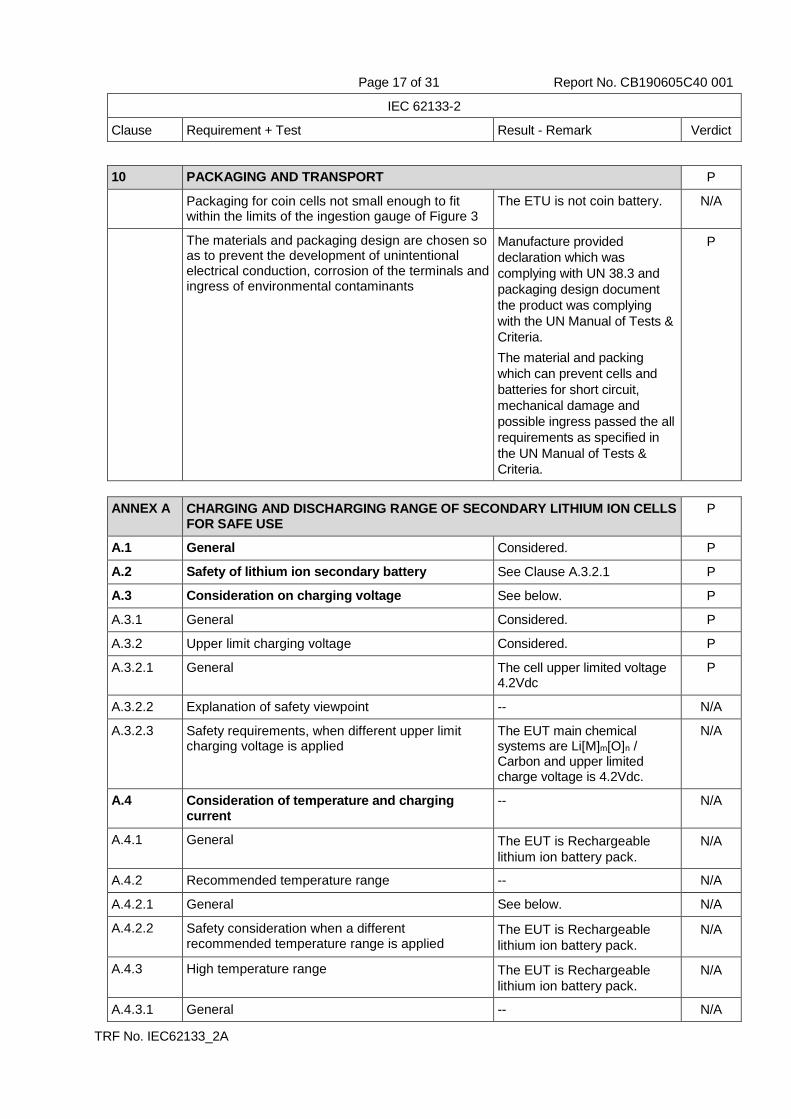
10 PACKAGING AND TRANSPORT P
Packaging for coin cells not small enough to fit within the limits of the ingestion gauge of Figure 3
The ETU is not coin battery. N/A
The materials and packaging design are chosen so as to prevent the development of unintentional electrical conduction, corrosion of the terminals and ingress of environmental contaminants
Manufacture provided
declaration which was
complying with UN 38.3 and
packaging design document
the product was complying
with the UN Manual of Tests &
Criteria.
The material and packing
which can prevent cells and
batteries for short circuit,
mechanical damage and
possible ingress passed the all
requirements as specified in
the UN Manual of Tests &
Criteria.
P
ANNEX A CHARGING AND DISCHARGING RANGE OF SECONDARY LITHIUM ION CELLS FOR SAFE USE
P
A.1 General Considered. P
A.2 Safety of lithium ion secondary battery See Clause A.3.2.1 P
A.3 Consideration on charging voltage See below. P
A.3.1 General Considered. P
A.3.2 Upper limit charging voltage Considered. P
A.3.2.1 General The cell upper limited voltage 4.2Vdc
P
A.3.2.2 Explanation of safety viewpoint -- N/A
A.3.2.3 Safety requirements, when different upper limit charging voltage is applied
The EUT main chemical systems are Li[M]m[O]n / Carbon and upper limited charge voltage is 4.2Vdc.
N/A
A.4 Consideration of temperature and charging current
-- N/A
A.4.1 General The EUT is Rechargeable
lithium ion battery pack.
N/A
A.4.2 Recommended temperature range -- N/A
A.4.2.1 General See below. N/A
A.4.2.2 Safety consideration when a different recommended temperature range is applied
The EUT is Rechargeable
lithium ion battery pack.
N/A
A.4.3 High temperature range The EUT is Rechargeable
lithium ion battery pack.
N/A
A.4.3.1 General -- N/A

Page 18 of 31 Report No. CB190605C40 001
IEC 62133-2
Clause Requirement + Test Result - Remark Verdict
TRF No. IEC62133_2A
A.4.3.2 Explanation of safety viewpoint -- N/A
A.4.3.3 Safety considerations when specifying charging conditions in the high temperature range
-- N/A
A.4.3.4 Safety considerations when specifying a new upper limit in the high temperature range
The EUT is Rechargeable
lithium ion battery pack.
N/A
A.4.4 Low temperature range The EUT is Rechargeable
lithium ion battery pack.
N/A
A.4.4.1 General -- N/A
A.4.4.2 Explanation of safety viewpoint -- N/A
A.4.4.3 Safety considerations, when specifying charging conditions in the low temperature range
-- N/A
A.4.4.4 Safety considerations when specifying a new lower limit in the low temperature range
The EUT is Rechargeable
lithium ion battery pack.
N/A
A.4.5 Scope of the application of charging current Certified cell used. N/A
A.4.6 Consideration of discharge Certified cell used. N/A
A.4.6.1 General Certified cell used. N/A
A.4.6.2 Final discharge voltage and explanation of safety viewpoint
Certified cell used. N/A
A.4.6.3 Discharge current and temperature range Certified cell used. N/A
A.4.6.4 Scope of application of the discharging current Certified cell used. N/A
A.5 Sample preparation Certified cell used. N/A
A.5.1 General Certified cell used. N/A
A.5.2 Insertion procedure for nickel particle to generate internal short
Certified cell used. N/A
A.5.3 Disassembly of charged cell Certified cell used. N/A
A.5.4 Shape of nickel particle Certified cell used. N/A
A.5.5 Insertion of nickel particle in cylindrical cell Certified cell used. N/A
A.5.5.1 Insertion of nickel particle in winding core Certified cell used. N/A
A.5.5.2 Marking the position of the nickel particle on both ends of the winding core of the separator
Certified cell used. N/A
A.5.6 Insertion of nickel particle in prismatic cell Certified cell used. N/A
A.6 Experimental procedure of the forced internal short-circuit test
Certified cell used. N/A
A.6.1 Material and tools for preparation of nickel particle Certified cell used. N/A
A.6.2 Example of a nickel particle preparation procedure Certified cell used. N/A
A.6.3 Positioning (or placement) of a nickel particle Certified cell used. N/A
A.6.4 Damaged separator precaution Certified cell used. N/A
A.6.5 Caution for rewinding separator and electrode Certified cell used. N/A
A.6.6 Insulation film for preventing short-circuit Certified cell used. N/A
Page 19 of 31 Report No. CB190605C40 001
IEC 62133-2
Clause Requirement + Test Result - Remark Verdict
TRF No. IEC62133_2A
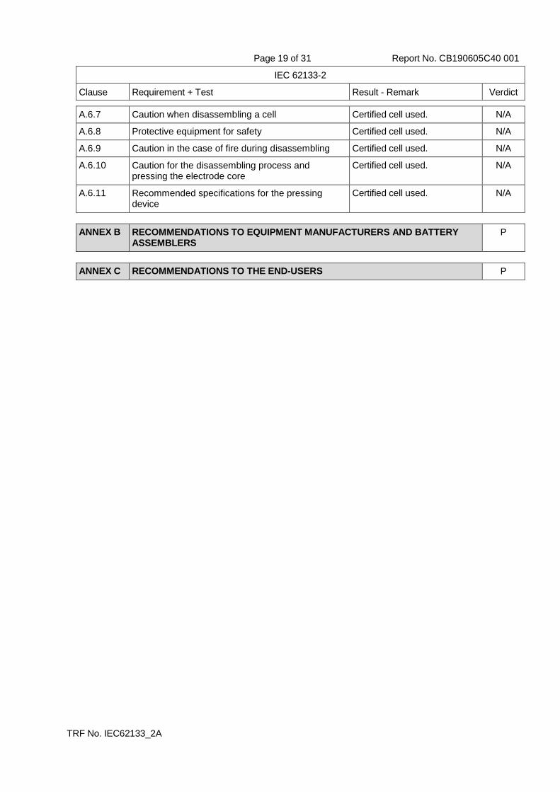
A.6.7 Caution when disassembling a cell Certified cell used. N/A
A.6.8 Protective equipment for safety Certified cell used. N/A
A.6.9 Caution in the case of fire during disassembling Certified cell used. N/A
A.6.10 Caution for the disassembling process and pressing the electrode core
Certified cell used. N/A
A.6.11 Recommended specifications for the pressing device
Certified cell used. N/A
ANNEX B RECOMMENDATIONS TO EQUIPMENT MANUFACTURERS AND BATTERY ASSEMBLERS
P
ANNEX C RECOMMENDATIONS TO THE END-USERS P

Page 20 of 31 Report No. CB190605C40 001
IEC 62133-2
Clause Requirement + Test Result - Remark Verdict
TRF No. IEC62133_2A
ANNEX D MEASUREMENT OF THE INTERNAL AC RESISTANCE FOR COIN CELLS N/A
D.1 General The EUT is not coin cell. N/A
D.2 Method The EUT is not coin cell. N/A
A sample size of three coin cells is required for this measurement ............................................................ :
(See appended table D.2) N/A
Coin cells with an internal resistance of less than or equal to 3 Ω are subjected to the testing according to Clause 6 and Table 1
The EUT is not coin cell. N/A
Coin cells with an internal resistance greater than 3 Ω require no further testing
The EUT is not coin cell. N/A
ANNEX E PACKAGING AND TRANSPORT P
ANNEX F COMPONENT STANDARDS REFERENCES N/A
Page 21 of 31 Report No. CB190605C40 001
IEC 62133-2
Clause Requirement + Test Result - Remark Verdict
TRF No. IEC62133_2A
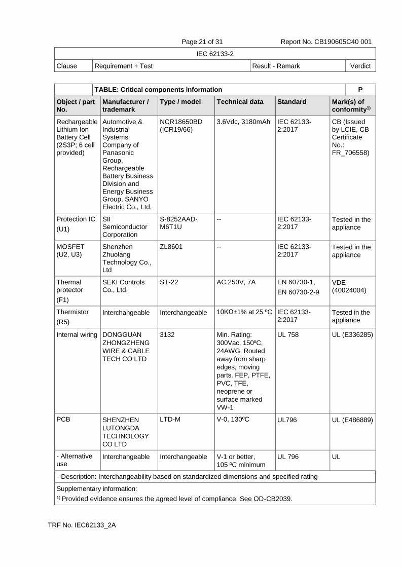
TABLE: Critical components information P
Object / part No.
Manufacturer / trademark
Type / model Technical data Standard Mark(s) of conformity1)
Rechargeable Lithium Ion Battery Cell (2S3P; 6 cell provided)
Automotive & Industrial Systems Company of Panasonic Group, Rechargeable Battery Business Division and Energy Business Group, SANYO Electric Co., Ltd.
NCR18650BD (ICR19/66)
3.6Vdc, 3180mAh IEC 62133-2:2017
CB (Issued by LCIE, CB Certificate No.: FR_706558)
Protection IC
(U1)
SII Semiconductor Corporation
S-8252AAD-M6T1U
-- IEC 62133-2:2017
Tested in the appliance
MOSFET (U2, U3)
Shenzhen Zhuolang Technology Co., Ltd
ZL8601 -- IEC 62133-2:2017
Tested in the appliance
Thermal protector
(F1)
SEKI Controls Co., Ltd.
ST-22 AC 250V, 7A EN 60730-1,
EN 60730-2-9
VDE (40024004)
Thermistor
(R5)
Interchangeable Interchangeable 10KΩ±1% at 25 ºC IEC 62133-2:2017
Tested in the appliance
Internal wiring DONGGUAN
ZHONGZHENG
WIRE & CABLE
TECH CO LTD
3132 Min. Rating:
300Vac, 150ºC,
24AWG. Routed
away from sharp
edges, moving
parts. FEP, PTFE,
PVC, TFE,
neoprene or
surface marked
VW-1
UL 758 UL (E336285)
PCB SHENZHEN
LUTONGDA
TECHNOLOGY
CO LTD
LTD-M V-0, 130ºC UL796 UL (E486889)
- Alternative use
Interchangeable Interchangeable V-1 or better,
105 ºC minimum
UL 796 UL
- Description: Interchangeability based on standardized dimensions and specified rating
Supplementary information:
1) Provided evidence ensures the agreed level of compliance. See OD-CB2039.
Page 22 of 31 Report No. CB190605C40 001
IEC 62133-2
Clause Requirement + Test Result - Remark Verdict
TRF No. IEC62133_2A
7.2.1 TABLE: Continuous charging at constant voltage (cells) N/A
Sample no. Recommended charging voltage
Vc (Vdc)
Recommended charging current
Irec (A)
OCV before test (Vdc)
Results
-- -- -- -- --
Supplementary information:
- No fire
- No explosion - No leakage - Others (please explain)
7.3.1 TABLE: External short-circuit (cell) N/A
Sample no. Ambient T (C) OCV before test (Vdc)
Resistance of
circuit ()
Maximum case temperature
rise T (K)
Results
Samples charged at charging temperature upper limit
-- -- -- -- -- --
Samples charged at charging temperature lower limit
-- -- -- -- -- --
Supplementary information:
- No fire
- No explosion - Others (please explain)

Page 23 of 31 Report No. CB190605C40 001
IEC 62133-2
Clause Requirement + Test Result - Remark Verdict
TRF No. IEC62133_2A
7.3.2 TABLE: External short-circuit (battery) P
Sample no. Ambient T
(C)
OCV before test (Vdc)
Resistance of circuit
(m)
Maximum case
temperature
rise T (K)
Component single fault condition
Results
HL18650-2S3P / 001
21.7 8.33 74 1.1 -- No fire, no explosion
HL18650-2S3P / 002
21.7 8.34 76 1.1
Protection IC
(U1)
(short circuit)
No fire, no explosion
HL18650-2S3P / 003
21.7 8.34 72 1.1
MOSFET (U2)
(short circuit)
No fire, no explosion
HL18650-2S3P / 004
21.7 8.34 78 1.0
Thermal protector
(F1)
(short circuit)
No fire, no explosion
HL18650-2S3P / 005
21.7 8.35 82 1.0
Thermistor
(C4)
(short circuit)
No fire, no explosion
Supplementary information:
- No fire - No explosion - Others (please explain)
7.3.5 TABLE: Crush (cells) N/A
Sample no. OCV before test (Vdc)
OCV at removal of crushing force
(Vdc)
Maximum force applied to the cell during crush (kN)
Results
Samples charged at charging temperature upper limit
-- -- -- -- --
Samples charged at charging temperature lower limit
-- -- -- -- --
Supplementary information:
- No fire
- No explosion - Others (please explain)

Page 24 of 31 Report No. CB190605C40 001
IEC 62133-2
Clause Requirement + Test Result - Remark Verdict
TRF No. IEC62133_2A
7.3.6 TABLE: Over-charging of battery P
Constant charging current (A) .................................. : 18.48
Supply voltage (Vdc) .................................................. : 10.08
Sample no. OCV before charging (Vdc)
Total charging time (minute)
Maximum outer case
temperature (C)
Results
HL18650-2S3P / 009
5.02 45 23.8 No fire, no explosion
HL18650-2S3P / 010
5.01 45 23.7 No fire, no explosion
HL18650-2S3P / 011
5.04 45 23.7 No fire, no explosion
HL18650-2S3P / 012
5.03 45 23.7 No fire, no explosion
HL18650-2S3P / 013
5.02 45 23.7 No fire, no explosion
Supplementary information:
- No fire
- No explosion - Others (please explain)
7.3.7 TABLE: Forced discharge (cells) N/A
Sample no. OCV before application of
reverse charge (Vdc)
Measured reverse charge It (A)
Lower limit discharge voltage
(Vdc)
Results
-- -- -- -- --
Supplementary information:
- No fire
- No explosion - Others (please explain)

Page 25 of 31 Report No. CB190605C40 001
IEC 62133-2
Clause Requirement + Test Result - Remark Verdict
TRF No. IEC62133_2A
7.3.8.1 TABLE: Vibration P
Sample no. OCV before test (Vdc)
OCV after test (Vdc)
Mass before test (g)
Mass after test (g)
Results
HL18650-2S3P / 014
8.34 8.33 293.98 293.96
No fire, no explosion, no rupture, no
leakage and no venting
HL18650-2S3P / 015
8.34 8.33 294.51 294.49
No fire, no explosion, no rupture, no
leakage and no venting
HL18650-2S3P / 016
8.34 8.34 294.23 294.22
No fire, no explosion, no rupture, no
leakage and no venting
Supplementary information:
- No fire - No explosion - No rupture - No leakage or venting - Others (please explain)
7.3.8.2 TABLE: Mechanical shock P
Sample no. OCV before test (Vdc)
OCV after test (Vdc)
Mass before test (g)
Mass after test (g)
Results
HL18650-2S3P / 017
8.34 8.33 293.42 293.41
No leakage, no venting, no rupture, no
explosion and no fire
HL18650-2S3P / 018
8.33 8.33 293.78 293.78
No leakage, no venting, no rupture, no
explosion and no fire
HL18650-2S3P / 019
8.34 8.34 293.50 293.49
No leakage, no venting, no rupture, no
explosion and no fire
Supplementary information:
- No fire - No explosion - No rupture - No leakage - No venting - Others (please explain)
Page 26 of 31 Report No. CB190605C40 001
IEC 62133-2
Clause Requirement + Test Result - Remark Verdict
TRF No. IEC62133_2A
7.3.9 TABLE: Forced internal short circuit (cells) N/A
Sample no. Chamber
ambient T (C)
OCV before test (Vdc)
Particle location 1)
Maximum applied
pressure (N)
Results
Samples charged at charging temperature upper limit
-- -- -- -- -- --
Samples charged at charging temperature lower limit
-- -- -- -- -- --
Supplementary information: 1) Identify one of the following: 1: Nickel particle inserted between positive and negative (active material) coated area.
2: Nickel particle inserted between positive aluminium foil and negative active material coated area.
- No fire
- Others (please explain)
D.2 TABLE: Internal AC resistance for coin cells N/A
Sample no. Ambient T (C) Store time (h) Resistance Rac () Results 1)
-- -- -- -- --
Supplementary information:
1) Coin cells with internal resistance less than or equal to 3 , see test result on corresponding tables
Page 27 of 31 Report No. CB190605C40 001
TRF No. IEC62133_2A
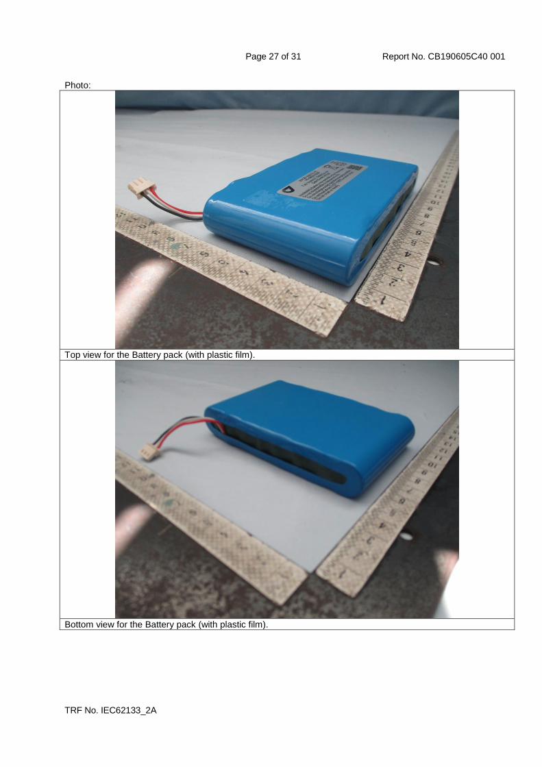
Photo:
Top view for the Battery pack (with plastic film).
Bottom view for the Battery pack (with plastic film).

Page 28 of 31 Report No. CB190605C40 001
TRF No. IEC62133_2A
Top view for the Battery pack (without plastic film).
Bottom view for the Battery pack (without plastic film).

Page 29 of 31 Report No. CB190605C40 001
TRF No. IEC62133_2A
Top view for the Battery pack (without corrugated paper)
Bottom view for the Battery pack (without corrugated paper).

Page 30 of 31 Report No. CB190605C40 001
TRF No. IEC62133_2A
Top view-1 of charge/discharge protection circuit board.
Top view-2 of charge/discharge protection circuit board.

Page 31 of 31 Report No. CB190605C40 001
TRF No. IEC62133_2A
Bottom view of charge/discharge protection circuit board.
Related Documents
![DtWx - NJAryaSamaj · DplS Dt [a Dx \m 7 5_ Dk hm [a [Sak^k F^k hu 7 5_ Dx KkWWt Dk UÌ\ D_Wt dkax gt gItS _hWt Dk lWU¥e hu dtU L C_ 8WDt J3 42F L Dk 4Å^^W D_ gÂ^ ]kFª Y_ KmdW](https://static.cupdf.com/doc/110x72/5fc6d69b3523d1018349c66a/dtwx-njaryasamaj-dpls-dt-a-dx-m-7-5-dk-hm-a-sakk-fk-hu-7-5-dx-kkwwt-dk.jpg)