61508-5 ª IEC: 1997 1 Version 4.0 05/12/97 COMMISSION CEI ELECTROTECHNIQUE IEC INTERNATIONALE 61508-5 INTERNATIONAL ELECTROTECHNICAL COMMISSION Functional safety of electrical/electronic/ programmable electronic safety-related systems Part 5: Examples of methods for the determination of safety integrity levels

Welcome message from author
This document is posted to help you gain knowledge. Please leave a comment to let me know what you think about it! Share it to your friends and learn new things together.
Transcript
61508-5 IEC: 1997 1 Version 4.0 05/12/97
COMMISSION CEIELECTROTECHNIQUE IECINTERNATIONALE 61508-5
INTERNATIONALELECTROTECHNICALCOMMISSION
Functional safety of electrical/electronic/programmable electronic safety-related systems
Part 5:Examples of methods for the determination ofsafety integrity levels
61508-5 IEC: 1997 2 Version 4.0 05/12/97
Contents
Foreword .................................................................................................................................... 3
Introduction................................................................................................................................. 5
1 Scope.................................................................................................................................... 7
2 Definitions and abbreviations .................................................................................................... 9
Annex A (informative) Risk and safety integrity - general concepts ................................................10
Annex B (informative) ALARP and tolerable risk concepts ............................................................16
Annex C (informative) Determination of safety integrity levels - a quantitative method ......................19
Annex D (informative) Determination of safety integrity levels - a qualitative method: risk graph ........22
Annex E (informative) Determination of safety integrity levels - a qualitative method: hazardousevent severity matrix ...................................................................................................................26
Figures
1 Overall framework of this standard ......................................................................................... 8
A.1 Risk reduction: general concepts..........................................................................................13
A.2 Risk and safety integrity concepts........................................................................................13
A.3 Allocation of safety requirements to the E/E/PE safety-related systems, other technologysafety-related systems and external risk reduction facilities ....................................................15
B.1 Tolerable risk and ALARP ....................................................................................................17
C.1 Safety integrity allocation: example for safety-related protection system ..................................21
D.1 Risk graph: general scheme.................................................................................................24
D.2 Risk graph: example (illustrates general principles only).........................................................24
E.1 Hazardous event severity matrix: example (illustrates general principles only)...........................27
Tables
B.1 Risk classification of accidents ............................................................................................18
B.2 Interpretation of risk classes ................................................................................................18
D.1 Example data relating to example risk graph (figure D.2).........................................................25
61508-5 IEC: 1997 3 Version 4.0 05/12/97
FUNCTIONAL SAFETY OF ELECTRICAL/ELECTRONIC/PROGRAMMABLEELECTRONIC SAFETY-RELATED SYSTEMS
Part 5: Examples of methods for the determination of safety integrity levels
FOREWORD
1) The IEC (International Electrotechnical Commission) is a worldwide organization for standardization comprising all nationalelectrotechnical committees (IEC national committees). The object of the IEC is to promote international cooperation on allquestions concerning standardization in the electrical and electronic fields. To this end and in addition to other activities, theIEC publishes international standards. Their preparation is entrusted to technical committees; any IEC national committeeinterested in the subject dealt with may participate in this preparatory work. International, governmental and non-governmentalorganizations liaising with the IEC also participate in this preparation. The IEC collaborates closely with the InternationalOrganization for Standardization (ISO) in accordance with conditions determined by agreement between the twoorganizations.
2) The formal decisions or agreements of the IEC on technical matters, prepared by technical committees on which all thenational committees having a special interest therein are represented, express, as nearly as possible, an internationalconsensus of opinion on the subjects dealt with.
3) They have the form of recommendations for international use published in the form of standards, technical reports or guidesand they are accepted by the national committees in that sense.
4) In order to promote international unification, IEC national committees undertake to apply IEC international standardstransparently to the maximum extent possible in their national and regional standards. Any divergence between the IECstandard and the corresponding national or regional standard shall be clearly indicated in the latter.
5) Attention is drawn to the possibility that some of the elements of IEC 61508 may be the subject of patent rights. IEC shall notbe held responsible for identifying any or all such patent rights.
6) The IEC has not laid down any procedure concerning marking as an indication of approval and has no responsibility when anitem of equipment is declared to comply with one of its standards.
IEC 61508-5 has been prepared by sub-committee 65A: System aspects, of IEC technical committeeFORMTEXT65: Industrial process measurement and controlFORMTEXT.
The text of this part is based on the following documents:
FDIS Report on voting 65A/xxx 65A/xxx
Full information on the voting for the approval of this standard can be found in the voting report indicated inthe above table.
Annexes A, B, C, D and E are for information only.
IEC 61508 consists of the following parts, under the general title “functional safety of electrical/electronic/programmable electronic safety-related systems”:
— Part 1: General requirements;
— Part 2: Requirements for electrical/electronic/programmable electronic safety-related systems;
— Part 3: Software requirements;
— Part 4: Definitions and abbreviations;
— Part 5: Examples of methods for the determination of safety integrity levels;

61508-5 IEC: 1997 4 Version 4.0 05/12/97
— Part 6: Guidelines on the application of parts 2 and 3;
— Part 7: Overview of techniques and measures.
This part 5 is to be used in conjunction with part 1.

61508-5 IEC: 1997 5 Version 4.0 05/12/97
Introduction
Systems comprised of electrical and/or electronic components have been used for many years to performsafety functions in most application sectors. Computer-based systems (generically referred to asprogrammable electronic systems (PESs)) are being used in all application sectors to perform non-safetyfunctions and, increasingly, to perform safety functions. If computer system technology is to be effectivelyand safely exploited, it is essential that those responsible for making decisions have sufficient guidance onthe safety aspects on which to make those decisions.
This standard sets out a generic approach for all safety lifecycle activities for systems comprised ofelectrical and/or electronic and/or programmable electronic components (electrical/electronic/ programmableelectronic systems (E/E/PESs)) that are used to perform safety functions. This unified approach has beenadopted in order that a rational and consistent technical policy be developed for all electrically-based safety-related systems. A major objective is to facilitate the development of application sector standards.
In most situations, safety is achieved by a number of protective systems which rely on many technologies(for example mechanical, hydraulic, pneumatic, electrical, electronic, programmable electronic). Any safetystrategy must therefore consider not only all the elements within an individual system (for example sensors,controlling devices and actuators) but also all the safety-related systems making up the total combination ofsafety-related systems. Therefore, while this standard is concerned with electrical/electronic/programmableelectronic (E/E/PE) safety-related systems, it may also provide a framework within which safety-relatedsystems based on other technologies may be considered.
It is recognised that there is a great variety of E/E/PES applications in a variety of application sectors andcovering a wide range of complexity, hazard and risk potentials. In any particular application, the exactprescription of safety measures will be dependent on many factors specific to the application. This standard,by being generic, will enable such a prescription to be formulated in future application sector internationalstandards.
This standard:
— considers all relevant overall, E/E/PES and software safety lifecycle phases (for example, from initialconcept, through design, implementation, operation and maintenance to decommissioning) whenE/E/PESs are used to perform safety functions;
— has been conceived with a rapidly developing technology in mind – the framework is sufficiently robustand comprehensive to cater for future developments;
— enables application sector international standards, dealing with safety-related E/E/PESs, to bedeveloped – the development of application sector international standards, within the framework of thisstandard, should lead to a high level of consistency (for example, of underlying principles, terminologyetc) both within application sectors and across application sectors; this will have both safety andeconomic benefits;
— provides a method for the development of the safety requirements specification necessary to achievethe required functional safety for E/E/PE safety-related systems;
— uses safety integrity levels for specifying the target level of safety integrity for the safety functions tobe implemented by the E/E/PE safety-related systems;
— adopts a risk-based approach for the determination of the safety integrity level requirements;
— sets numerical target failure measures for E/E/PE safety-related systems which are linked to thesafety integrity levels;
61508-5 IEC: 1997 6 Version 4.0 05/12/97
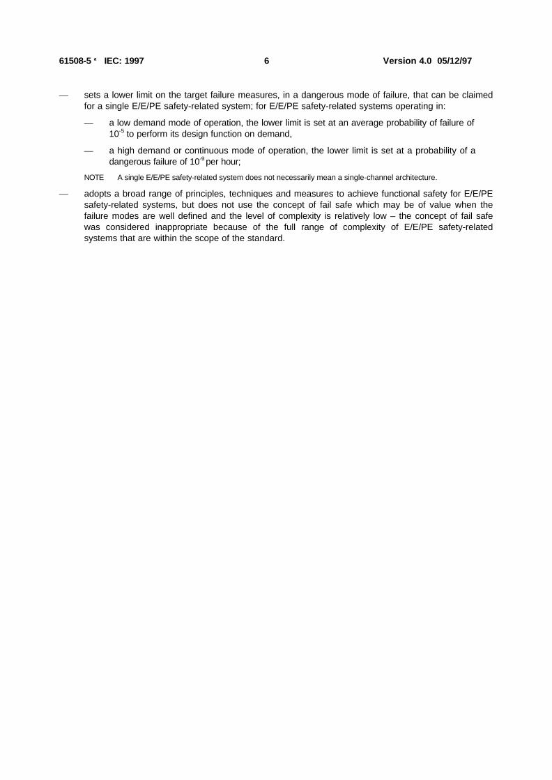
— sets a lower limit on the target failure measures, in a dangerous mode of failure, that can be claimedfor a single E/E/PE safety-related system; for E/E/PE safety-related systems operating in:
— a low demand mode of operation, the lower limit is set at an average probability of failure of10-5 to perform its design function on demand,
— a high demand or continuous mode of operation, the lower limit is set at a probability of adangerous failure of 10-9 per hour;
NOTE A single E/E/PE safety-related system does not necessarily mean a single-channel architecture.
— adopts a broad range of principles, techniques and measures to achieve functional safety for E/E/PEsafety-related systems, but does not use the concept of fail safe which may be of value when thefailure modes are well defined and the level of complexity is relatively low – the concept of fail safewas considered inappropriate because of the full range of complexity of E/E/PE safety-relatedsystems that are within the scope of the standard.

61508-5 IEC: 1997 7 Version 4.0 05/12/97
AUTOTEXTMERGEFORMATFUNCTIONAL SAFETY OFELECTRICAL/ELECTRONIC/PROGRAMMABLE ELECTRONIC SAFETY-RELATED
SYSTEMSAUTOTEXTMERGEFORMAT
Part 5: Examples of methods for the determination of safety integrity levels
1 Scope
1.1 This part provides information on:
— the underlying concepts of risk and the relationship of risk to safety integrity (annex A);
— a number of methods that will enable the safety integrity levels for the E/E/PE safety-related systems,other technology safety-related systems and external risk reduction facilities to be determined(annexes B, C, D and E).
1.2 The method selected will depend upon the application sector and the specific circumstances underconsideration. Annexes B, C, D and E illustrate quantitative and qualitative approaches and have beensimplified in order to illustrate the underlying principles. These annexes have been included to illustrate thegeneral principles of a number of methods but do not provide a definitive account. Those intending to applythe methods indicated in these annexes should consult the source material referenced.
NOTE For more information on the approaches illustrated in annexes B, D and E, see references [51], [47] and [48]respectively in annex C of part 1. See also reference [52] in annex C of part 1 for a description of an additional approach.
1.3 Parts 1, 2, 3 and 4 of this standard are basic safety publications, although this status does notapply in the context of low complexity E/E/PE safety-related systems (see 3.4.4 of part 4). As basic safetypublications, they are intended for use by Technical Committees in the preparation of standards inaccordance with the principles contained in ISO/IEC Guide 104 and ISO/IEC Guide 51. One of theresponsibilities of a Technical Committee is, wherever applicable, to make use of basic safety publicationsin the preparation of its own publications. IEC 61508 is also intended for use as astand-alone standard.
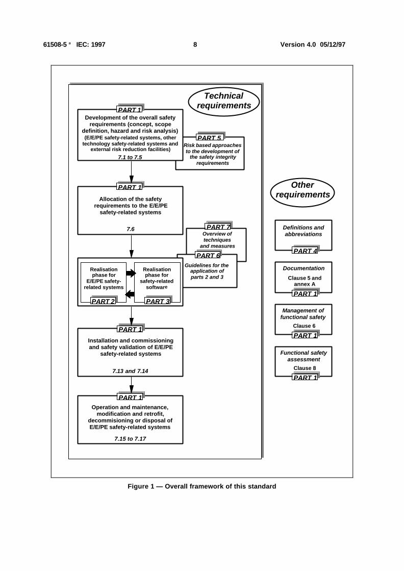
1.4 Figure 1 shows the overall framework for parts 1 to 7 of this standard and indicates the role thatpart 5 plays in the achievement of functional safety for E/E/PE safety-related systems.
61508-5 IEC: 1997 8 Version 4.0 05/12/97
Guidelines for the application of parts 2 and 3
Overview of techniques
and measures
PART 7
PART 6
Risk based approaches to the development of
the safety integrity requirements
PART 5
7.6
Realisation phase for
E/E/PE safety- related systems
Realisation phase for
safety-related software
PART 3PART 2
Allocation of the safety requirements to the E/E/PE
safety-related systems
Development of the overall safety requirements (concept, scope
definition, hazard and risk analysis)(E/E/PE safety-related systems, other
technology safety-related systems and external risk reduction facilities)
7.1 to 7.5
PART 1
PART 1
Installation and commissioning and safety validation of E/E/PE
safety-related systems
7.13 and 7.14
PART 1
Operation and maintenance, modification and retrofit,
decommisioning or disposal of E/E/PE safety-related systems
PART 1
7.15 to 7.17
Management of functional safety
PART 1
Documentation
PART 1
Definitions and abbreviations
PART 4
Functional safety assessment
PART 1
Clause 6
Clause 8
Clause 5 andannex A
Other requirements
Technical requirements
Figure 1 — Overall framework of this standard

61508-5 IEC: 1997 9 Version 4.0 05/12/97
2 Definitions and abbreviations
For the purposes of this standard, the definitions and abbreviations given in part 4 apply.
61508-5 IEC: 1997 10 Version 4.0 05/12/97
Annex A(informative)
Risk and safety integrity - general concepts
A.1 General
This annex provides information on the underlying concepts of risk and the relationship of risk to safetyintegrity.
A.2 Necessary risk reduction
The necessary risk reduction (see 3.5.14 of part 4) is the reduction in risk that has to be achieved to meetthe tolerable risk for a specific situation (which may be stated either qualitatively1 or quantitatively2). Theconcept of necessary risk reduction is of fundamental importance in the development of the safetyrequirements specification for the E/E/PE safety-related systems (in particular, the safety integrityrequirements part of the safety requirements specification). The purpose of determining the tolerable risk fora specific hazardous event is to state what is deemed reasonable with respect to both the frequency (orprobability) of the hazardous event and its specific consequences. Safety-related systems are designed toreduce the frequency (or probability) of the hazardous event and/or the consequences of the hazardousevent.
The tolerable risk will depend on many factors (for example, severity of injury, the number of people exposedto danger, the frequency at which a person or people are exposed to danger and the duration of theexposure). Important factors will be the perception and views of those exposed to the hazardous event. Inarriving at what constitutes a tolerable risk for a specific application, a number of inputs are considered.These include:
— guidelines from the appropriate safety regulatory authority;
— discussions and agreements with the different parties involved in the application;
— industry standards and guidelines;
— international discussions and agreements – the role of national and international standards arebecoming increasingly important in arriving at tolerable risk criteria for specific applications;
— the best independent industrial, expert and scientific advice from advisory bodies;
— legal requirements – both general and those directly relevant to the specific application.
1 In determining the tolerable risk, the necessary risk reduction will need to be established. Annexes D and E of part 5 outlinequalitative methods, although in the examples quoted the necessary risk reduction is incorporated implicitly rather than statedexplicitly.
2 For example, that the hazardous event, leading to a specific consequence, shall not occur with a frequency greater thanone in 108 hours.
61508-5 IEC: 1997 11 Version 4.0 05/12/97
A.3 Role of E/E/PE safety-related systems
E/E/PE safety-related systems contribute towards meeting the necessary risk reduction in order to meetthe tolerable risk.
A safety-related system both:
— implements the required safety functions necessary to achieve a safe state for the equipment undercontrol or to maintain a safe state for the equipment under control; and
— is intended to achieve, on its own or with other E/E/PE safety-related systems, other technologysafety-related systems or external risk reduction facilities, the necessary safety integrity for therequired safety functions (3.4.1 of part 4).
NOTE 1 The first part of the definition specifies that the safety-related system must perform the safety functions which wouldbe specified in the safety functions requirements specification. For example, the safety functions requirements specification maystate that when the temperature reaches x, valve y shall open to allow water to enter the vessel.
NOTE 2 The second part of the definition specifies that the safety functions must be performed by the safety-related systemswith the degree of confidence appropriate to the application, in order that the tolerable risk will be achieved.
A person could be an integral part of an E/E/PE safety-related system. For example, a person could receiveinformation, on the state of the EUC, from a display screen and perform a safety action based on thisinformation.
E/E/PE safety-related systems can operate in a low demand mode of operation or high demand orcontinuous mode of operation (see 3.5.12 of part 4).
A.4 Safety integrity
Safety integrity is defined as the probability of a safety-related system satisfactorily performing the requiredsafety functions under all the stated conditions within a stated period of time (3.5.2 of part 4). Safetyintegrity relates to the performance of the safety-related systems in carrying out the safety functions (thesafety functions to be performed will be specified in the safety functions requirements specification).
Safety integrity is considered to be composed of the following two elements.
— Hardware safety integrity – that part of safety integrity relating to random hardware failures in adangerous mode of failure (see 3.5.5 of part 4). The achievement of the specified level of safety-relatedhardware safety integrity can be estimated to a reasonable level of accuracy, and the requirementscan therefore be apportioned between subsystems using the normal rules for the combination ofprobabilities. It may be necessary to use redundant architectures to achieve adequate hardwaresafety integrity.
— Systematic safety integrity – that part of safety integrity relating to systematic failures in a dangerousmode of failure (see 3.5.4 of part 4). Although the mean failure rate due to systematic failures may becapable of estimation, the failure data obtained from design faults and common cause failures meansthat the distribution of failures can be hard to predict. This has the effect of increasing the uncertaintyin the failure probability calculations for a specific situation (for example the probability of failure of asafety-related protection system). A judgement therefore has to be made on the selection of the besttechniques to minimise this uncertainty. Note that it is not necessarily the case that measures toreduce the probability of random hardware failure will have a corresponding effect on the probability ofsystematic failure. Techniques such as redundant channels of identical hardware, which are veryeffective at controlling random hardware failures, are of little use in reducing systematic failures.
61508-5 IEC: 1997 12 Version 4.0 05/12/97
The required safety integrity of the E/E/PE safety-related systems, other technology safety-related systemsand external risk reduction facilities, must be of such a level so as to ensure that:
— the failure frequency of the safety-related systems is sufficiently low to prevent the hazardous eventfrequency exceeding that required to meet the tolerable risk; and/or
— the safety-related systems modify the consequences of failure to the extent required to meet thetolerable risk.
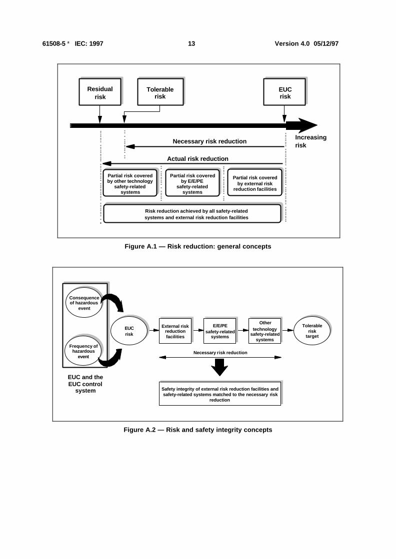
Figure A.1 illustrates the general concepts of risk reduction. The general model assumes that:
— there is an EUC and an EUC control system;
— there are associated human factor issues;
— the safety protective features comprise:
— external risk reduction facilities,
— E/E/PE safety-related systems,
— other technology safety-related systems.
NOTE Figure A.1 is a generalised risk model to illustrate the general principles. The risk model for a specific application willneed to be developed taking into account the specific manner in which the necessary risk reduction is actually being achieved bythe E/E/PE safety-related systems and/or other technology safety-related systems and/or external risk reduction facilities. Theresulting risk model may therefore differ from that shown in figure A.1.
The various risks indicated in figure A.1 are as follows:
— EUC risk – the risk existing for the specified hazardous events for the EUC, the EUC control systemand associated human factor issues – no designated safety protective features are considered in thedetermination of this risk (see 3.2.4 of part 4);
— tolerable risk – the risk which is accepted in a given context based on the current values of society(see 3.1.6 of part 4);
— residual risk – in the context of this standard, the residual risk is that remaining for the specifiedhazardous events for the EUC, the EUC control system, human factor issues but with the addition ofexternal risk reduction facilities, E/E/PE safety-related systems and other technology safety-relatedsystems (see also 3.1.7 of part 4).
The EUC risk is a function of the risk associated with the EUC itself but taking into account the riskreduction brought about by the EUC control system. To prevent unreasonable claims for the safety integrityof the EUC control system, this standard places constraints on the claims that can be made (see 7.5.2.5 ofpart 1).
The necessary risk reduction is achieved by a combination of all the safety protective features. Thenecessary risk reduction to achieve the specified tolerable risk, from a starting point of the EUC risk, isshown in figure A.1.
61508-5 IEC: 1997 13 Version 4.0 05/12/97
Tolerable risk
EUC risk
Necessary risk reduction
Actual risk reduction
Increasingrisk
Residualrisk
Partial risk covered by E/E/PE
safety-related systems
Partial risk covered by other technology
safety-related systems
Partial risk covered by external risk
reduction facilities
Risk reduction achieved by all safety-relatedsystems and external risk reduction facilities
Figure A.1 — Risk reduction: general concepts
Othertechnology
safety-related systems
EUC and the EUC control
system
Frequency of
hazardous event
Consequence of hazardous
event
EUCrisk
Safety integrity of external risk reduction facilities and safety-related systems matched to the necessary risk
reduction
Necessary risk reduction
External risk reduction facilities
Tolerable
risk target
E/E/PEsafety-related
systems
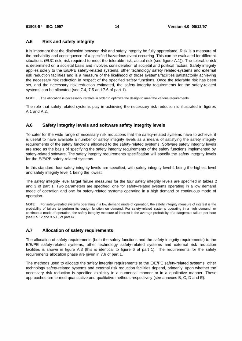
Figure A.2 — Risk and safety integrity concepts
61508-5 IEC: 1997 14 Version 4.0 05/12/97
A.5 Risk and safety integrity
It is important that the distinction between risk and safety integrity be fully appreciated. Risk is a measure ofthe probability and consequence of a specified hazardous event occurring. This can be evaluated for differentsituations (EUC risk, risk required to meet the tolerable risk, actual risk (see figure A.1)). The tolerable riskis determined on a societal basis and involves consideration of societal and political factors. Safety integrityapplies solely to the E/E/PE safety-related systems, other technology safety related-systems and externalrisk reduction facilities and is a measure of the likelihood of those systems/facilities satisfactorily achievingthe necessary risk reduction in respect of the specified safety functions. Once the tolerable risk has beenset, and the necessary risk reduction estimated, the safety integrity requirements for the safety-relatedsystems can be allocated (see 7.4, 7.5 and 7.6 of part 1).
NOTE The allocation is necessarily iterative in order to optimize the design to meet the various requirements.
The role that safety-related systems play in achieving the necessary risk reduction is illustrated in figuresA.1 and A.2.
A.6 Safety integrity levels and software safety integrity levels
To cater for the wide range of necessary risk reductions that the safety-related systems have to achieve, itis useful to have available a number of safety integrity levels as a means of satisfying the safety integrityrequirements of the safety functions allocated to the safety-related systems. Software safety integrity levelsare used as the basis of specifying the safety integrity requirements of the safety functions implemented bysafety-related software. The safety integrity requirements specification will specify the safety integrity levelsfor the E/E/PE safety-related systems.
In this standard, four safety integrity levels are specified, with safety integrity level 4 being the highest leveland safety integrity level 1 being the lowest.
The safety integrity level target failure measures for the four safety integrity levels are specified in tables 2and 3 of part 1. Two parameters are specified, one for safety-related systems operating in a low demandmode of operation and one for safety-related systems operating in a high demand or continuous mode ofoperation.
NOTE For safety-related systems operating in a low demand mode of operation, the safety integrity measure of interest is theprobability of failure to perform its design function on demand. For safety-related systems operating in a high demand orcontinuous mode of operation, the safety integrity measure of interest is the average probability of a dangerous failure per hour(see 3.5.12 and 3.5.13 of part 4).
A.7 Allocation of safety requirements
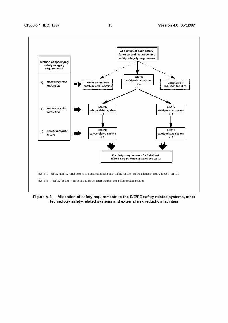
The allocation of safety requirements (both the safety functions and the safety integrity requirements) to theE/E/PE safety-related systems, other technology safety-related systems and external risk reductionfacilities is shown in figure A.3 (this is identical to figure 6 of part 1). The requirements for the safetyrequirements allocation phase are given in 7.6 of part 1.
The methods used to allocate the safety integrity requirements to the E/E/PE safety-related systems, othertechnology safety-related systems and external risk reduction facilities depend, primarily, upon whether thenecessary risk reduction is specified explicitly in a numerical manner or in a qualitative manner. Theseapproaches are termed quantitative and qualitative methods respectively (see annexes B, C, D and E).
61508-5 IEC: 1997 15 Version 4.0 05/12/97
Allocation of each safety function and its associatedsafety integrity requirement
Other technologysafety-related systems
External riskreduction facilities
E/E/PEsafety-related system
# 1# 2
E/E/PEsafety-related system
# 1
E/E/PEsafety-related system
# 2
E/E/PEsafety-related system
# 1
E/E/PEsafety-related system
# 2
For design requirements for individual E/E/PE safety-related systems see part 2
NOTE 1 Safety integrity requirements are associated with each safety function before allocation (see 7.5.2.6 of part 1).
NOTE 2 A safety function may be allocated across more than one safety-related system.
a) necessary risk reduction
b) necessary risk reduction
c) safety integrity levels
Method of specifying safety integrity requirements
Figure A.3 — Allocation of safety requirements to the E/E/PE safety-related systems, othertechnology safety-related systems and external risk reduction facilities
61508-5 IEC: 1997 16 Version 4.0 05/12/97
Annex B(informative)
ALARP and tolerable risk concepts
B.1 General
This annex considers one particular approach to the achievement of a tolerable risk. The intention is not toprovide a definitive account of the method but rather an illustration of the general principles. Those intendingto apply the methods indicated in this annex should consult the source material referenced.
B.2 ALARP model
B.2.1 Introduction
Subclause A.2 outlines the main tests that are applied in regulating industrial risks and indicates that theactivities involve determining whether:
a) the risk is so great that it must be refused altogether; or
b) the risk is, or has been made, so small as to be insignificant; or
c) the risk falls between the two states specified in a) and b) above and has been reduced to the lowestpracticable level, bearing in mind the benefits resulting from its acceptance and taking into accountthe costs of any further reduction.
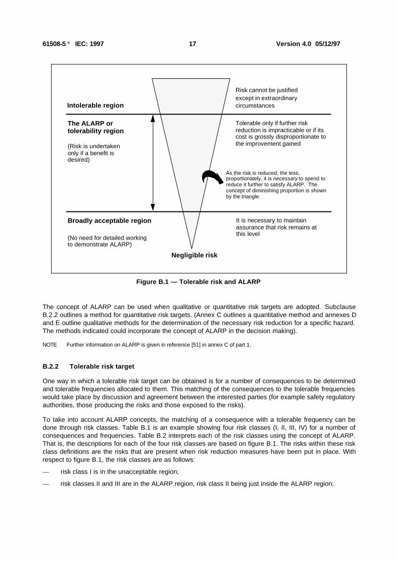
With respect to c), the ALARP principle requires that any risk must be reduced so far as is reasonablypracticable, or to a level which is as low as reasonably practicable (these last 5 words form the abbreviationALARP). If a risk falls between the two extremes (ie the unacceptable region and broadly acceptable region)and the ALARP principle has been applied, then the resulting risk is the tolerable risk for that specificapplication. This three zone approach is shown in figure B.1.
Above a certain level, a risk is regarded as intolerable and cannot be justified in any ordinary circumstance.
Below that level, there is the tolerability region where an activity is allowed to take place provided theassociated risks have been made as low as reasonably practicable. Tolerable here is different fromacceptable - it indicates a willingness to live with a risk so as to secure certain benefits, at the same timeexpecting it to be kept under review and reduced as and when this can be done. Here a cost benefitassessment is required either explicitly or implicitly to weigh the cost and the need or otherwise foradditional safety measures. The higher the risk, the more proportionately would be expected to be spent toreduce it. At the limit of tolerability, expenditure in gross disproportion to the benefit would be justified. Herethe risk will by definition be substantial, and equity requires that a considerable effort is justified even toachieve a marginal reduction.
Where the risks are less significant, the less proportionately, need be spent to reduce them and at the lowerend of the tolerability region, a balance between costs and benefits will suffice.
Below the tolerability region, the levels of risk are regarded as so insignificant that the regulator need notask for further improvements. This is the broadly acceptable region where the risks are small in comparisonwith the every day risks we all experience. While in the broadly acceptable region, there is no need for adetailed working to demonstrate ALARP; however, it is necessary to remain vigilant to ensure that the riskremains at this level.
61508-5 IEC: 1997 17 Version 4.0 05/12/97
Intolerable region
Broadly acceptable region
(No need for detailed working to demonstrate ALARP)
Negligible risk
Risk cannot be justifiedexcept in extraordinarycircumstances
Tolerable only if further risk reduction is impracticable or if its cost is grossly disproportionate to the improvement gained
It is necessary to maintain assurance that risk remains at this level
The ALARP or tolerability region
(Risk is undertaken only if a benefit is desired)
As the risk is reduced, the less, proportionately, it is necessary to spend to reduce it further to satisfy ALARP. The concept of diminishing proportion is shown by the triangle.
Figure B.1 — Tolerable risk and ALARP
The concept of ALARP can be used when qualitative or quantitative risk targets are adopted. SubclauseB.2.2 outlines a method for quantitative risk targets. (Annex C outlines a quantitative method and annexes Dand E outline qualitative methods for the determination of the necessary risk reduction for a specific hazard.The methods indicated could incorporate the concept of ALARP in the decision making).
NOTE Further information on ALARP is given in reference [51] in annex C of part 1.
B.2.2 Tolerable risk target
One way in which a tolerable risk target can be obtained is for a number of consequences to be determinedand tolerable frequencies allocated to them. This matching of the consequences to the tolerable frequencieswould take place by discussion and agreement between the interested parties (for example safety regulatoryauthorities, those producing the risks and those exposed to the risks).
To take into account ALARP concepts, the matching of a consequence with a tolerable frequency can bedone through risk classes. Table B.1 is an example showing four risk classes (I, II, III, IV) for a number ofconsequences and frequencies. Table B.2 interprets each of the risk classes using the concept of ALARP.That is, the descriptions for each of the four risk classes are based on figure B.1. The risks within these riskclass definitions are the risks that are present when risk reduction measures have been put in place. Withrespect to figure B.1, the risk classes are as follows:
— risk class I is in the unacceptable region;
— risk classes II and III are in the ALARP region, risk class II being just inside the ALARP region;

61508-5 IEC: 1997 18 Version 4.0 05/12/97
— risk class IV is in the broadly acceptable region.
For each specific situation, or sector comparable industries, a table similar to table B.1 would be developedtaking into account a wide range of social, political and economic factors. Each consequence would bematched against a frequency and the table populated by the risk classes. For example, frequent in table B.1could denote an event that is likely to be continually experienced, which could be specified as a frequencygreater than 10 per year. A critical consequence could be a single death and/or multiple severe injuries orsevere occupational illness.
Table B.1 — Risk classification of accidents
Frequency Consequence Catastrophic Critical Marginal Negligible Frequent I I I II Probable I I II III Occasional I II III III Remote II III III IV Improbable III III IV IV Incredible IV IV IV IV NOTE 1 The actual population with risk classes I, II, III and IV will be sector dependent and will alsodepend upon what the actual frequencies are for frequent; probable etc. Therefore, this tableshould be seen as an example of how such a table could be populated, rather than as aspecification for future use. NOTE 2 Determination of the safety integrity level from the frequencies in this table is outlined inannex C.
Table B.2 — Interpretation of risk classes
Risk class Interpretation Class I Intolerable risk Class II Undesirable risk, and tolerable only if risk reduction is impracticable or if the
costs are grossly disproportionate to the improvement gained Class III Tolerable risk if the cost of risk reduction would exceed the improvement gained Class IV Negligible risk
61508-5 IEC: 1997 19 Version 4.0 05/12/97
Annex C(informative)
Determination of safety integrity levels: a quantitative method
C.1 General
This annex outlines how the safety integrity levels can be determined if a quantitative approach is adoptedand illustrates how the information contained in tables such as table B.1 can be used. A quantitativeapproach is of particular value when:
— the tolerable risk is to be specified in a numerical manner (for example that a specified consequenceshould not occur with a greater frequency than 1 in 104 years); or
— numerical targets have been specified for the safety integrity levels for the safety-related systems.Such targets have been specified in this standard (see tables 2 and 3 of part 1).
This annex is not intended to be a definitive account of the method but is intended to illustrate the generalprinciples. It is particularly applicable when the risk model is as indicated in figures A.1 and A.2.
C.2 General method
The model used to illustrate the general principles is that shown in figure A.1. The key steps in the methodare as follows and will need to be done for each safety function to be implemented by the E/E/PE safety-related system:
— determine the tolerable risk from a table such as table B.1;
— determine the EUC risk;
— determine the necessary risk reduction to meet the tolerable risk;
— allocate the necessary risk reduction to the E/E/PE safety-related systems, other technology safety-related systems and external risk reduction facilities (see 7.6 of part 1).
Table B.1 is populated with risk frequencies and allows a numerical tolerable risk target (Ft) to be specified.
The frequency associated with the risk that exists for the EUC, including the EUC control system andhuman factor issues (the EUC risk), without any protective features, can be estimated using quantitative riskassessment methods. This frequency with which a hazardous event could occur without protective featurespresent (Fnp) is one of two components of the EUC risk; the other component is the consequence of thehazardous event. Fnp may be determined by:
— analysis of failure rates from comparable situations;
— data from relevant databases;
— calculation using appropriate predictive methods.
This standard places constraints on the minimum failure rates that can be claimed for the EUC controlsystem (see 7.5.2.5 of part 1). If it is to be claimed that the EUC control system has a failure rate less thanthese minimum failure rates, then the EUC control system shall be considered a safety-related system andshall be subject to all the requirements for safety-related systems in this standard.

61508-5 IEC: 1997 20 Version 4.0 05/12/97
C.3 Example calculation
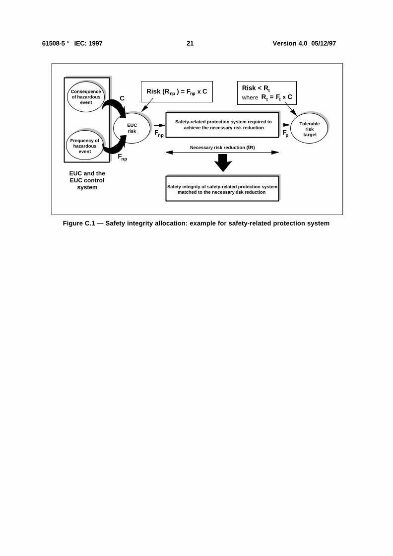
Figure C.1 provides an example of how to calculate the target safety integrity for a single safety-relatedprotection system. For such a situation:
PFDavg ≤ Ft / Fnp
where:
— PFDavg is the average probability of failure on demand of the safety-related protection system, which isthe safety integrity failure measure for safety-related protection systems operating in a low demandmode of operation (see table 2 of part 1 and 3.5.12 of part 4);
— Ft is the tolerable risk frequency;
— Fnp is the demand rate on the safety-related protection system.
Also in figure C.1:
— C is the consequence of the hazardous event;
— Fp is the risk frequency with the protective features in place.
It can be seen that determination of Fnp for the EUC is important because of its relationship to PFDavg andhence to the safety integrity level of the safety-related protection system.
The necessary steps in obtaining the safety integrity level (when the consequence C remains constant) aregiven below (as in figure C.1), for the situation where the entire necessary risk reduction is achieved by asingle safety-related protection system which must reduce the hazard rate, as a minimum, from Fnp to Ft:
— determine the frequency element of the EUC risk without the addition of any protective features (Fnp);
— determine the consequence (C) without the addition of any protective features;
— determine, by use of table B.1, whether for frequency (Fnp) and consequence (C) a tolerable risk levelis achieved. If, through the use of table B.1, this leads to risk class I, then further risk reduction isrequired. Risk class IV or III would be tolerable risks. Risk class II would require further investigation;
NOTE Table B.1 is used to check whether or not further risk reduction measures are necessary, since it may bepossible to achieve a tolerable risk without the addition of any protective features.
— determine the probability of failure on demand for the safety-related protection system (PFDavg) tomeet the necessary risk reduction (∆R). For a constant consequence in the specific situationdescribed, PFDavg = (Ft / Fnp) = ∆R;
— for PFDavg = (Ft / Fnp), the safety integrity level can be obtained from table 2 of part 1 (for example, forPFDavg = 10-2 - 10-3, the safety integrity level = 2).
61508-5 IEC: 1997 21 Version 4.0 05/12/97
Safety integrity of safety-related protection system matched to the necessary risk reduction
Necessary risk reduction (∆R)
Safety-related protection system required to achieve the necessary risk reduction
EUC and the EUC control
system
Frequency of
hazardous event
Consequence of hazardous
event
Fnp
C
Fnp Fp
Risk (R ) = F x CnpnpRisk < R twhere R = F X Ctt
EUCrisk
Tolerable risk
target
Figure C.1 — Safety integrity allocation: example for safety-related protection system
61508-5 IEC: 1997 22 Version 4.0 05/12/97
Annex D(informative)
Determination of safety integrity levels - a qualitative method:risk graph
D.1 General
This annex describes the risk graph method, which is a qualitative method that enables the safety integritylevel of a safety-related system to be determined from a knowledge of the risk factors associated with theEUC and the EUC control system. It is particularly applicable when the risk model is as indicated in figuresA.1 and A.2.
Where a qualitative approach is adopted, in order to simplify matters a number of parameters are introducedwhich together describe the nature of the hazardous situation when safety-related systems fail or are notavailable. One parameter is chosen from each of four sets, and the selected parameters are then combinedto decide the safety integrity level allocated to the safety-related systems. These parameters:
— allow a meaningful graduation of the risks to be made, and
— contain the key risk assessment factors.
This annex is not intended to be a definitive account of the method but is intended to illustrate the generalprinciples. Those intending to apply the methods indicated in this annex should consult the source materialreferenced.
D.2 Risk graph synthesis
The following simplified procedure is based on the following equation:
R = f x C
where:
— R is the risk with no safety-related systems in place;
— f is the frequency of the hazardous event with no safety-related systems in place;
— C is the consequence of the hazardous event (the consequences could be related to harm associatedwith health and safety or harm from environmental damage).
The frequency of the hazardous event (f) is, in this case, considered to be made up of three influencingfactors:
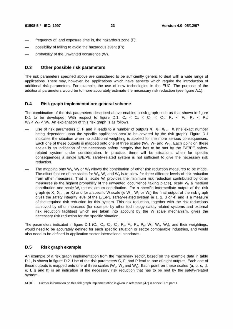
— frequency of, and exposure time in, the hazardous zone;
— the possibility of avoiding the hazardous event; and
— the probability of the hazardous event taking place without the addition of any safety-related systems(but having in place external risk reduction facilities) – this is termed the probability of the unwantedoccurrence.
This produces the following four risk parameters:
— consequence of the hazardous event (C);
61508-5 IEC: 1997 23 Version 4.0 05/12/97
— frequency of, and exposure time in, the hazardous zone (F);
— possibility of failing to avoid the hazardous event (P);
— probability of the unwanted occurrence (W).
D.3 Other possible risk parameters
The risk parameters specified above are considered to be sufficiently generic to deal with a wide range ofapplications. There may, however, be applications which have aspects which require the introduction ofadditional risk parameters. For example, the use of new technologies in the EUC. The purpose of theadditional parameters would be to more accurately estimate the necessary risk reduction (see figure A.1).
D.4 Risk graph implementation: general scheme
The combination of the risk parameters described above enables a risk graph such as that shown in figureD.1 to be developed. With respect to figure D.1: CA < CB < CC < CD; FA < FB; PA < PB;W1 < W2 < W3. An explanation of this risk graph is as follows.
— Use of risk parameters C, F and P leads to a number of outputs X1, X2, X3 ... Xn (the exact numberbeing dependent upon the specific application area to be covered by the risk graph). Figure D.1indicates the situation when no additional weighting is applied for the more serious consequences.Each one of these outputs is mapped onto one of three scales (W1, W2 and W3). Each point on thesescales is an indication of the necessary safety integrity that has to be met by the E/E/PE safety-related system under consideration. In practice, there will be situations when for specificconsequences a single E/E/PE safety-related system is not sufficient to give the necessary riskreduction.
— The mapping onto W1, W2 or W3 allows the contribution of other risk reduction measures to be made.The offset feature of the scales for W1, W2 and W3 is to allow for three different levels of risk reductionfrom other measures. That is, scale W3 provides the minimum risk reduction contributed by othermeasures (ie the highest probability of the unwanted occurrence taking place), scale W2 a mediumcontribution and scale W1 the maximum contribution. For a specific intermediate output of the riskgraph (ie X1, X2 ... or X6) and for a specific W scale (ie W1, W2 or W3) the final output of the risk graphgives the safety integrity level of the E/E/PE safety-related system (ie 1, 2, 3 or 4) and is a measureof the required risk reduction for this system. This risk reduction, together with the risk reductionsachieved by other measures (for example by other technology safety-related systems and externalrisk reduction facilities) which are taken into account by the W scale mechanism, gives thenecessary risk reduction for the specific situation.
The parameters indicated in figure D.1 (CA, CB, CC, CD, FA, FB, PA, PB, W1, W2, W3), and their weightings,would need to be accurately defined for each specific situation or sector comparable industries, and wouldalso need to be defined in application sector international standards.
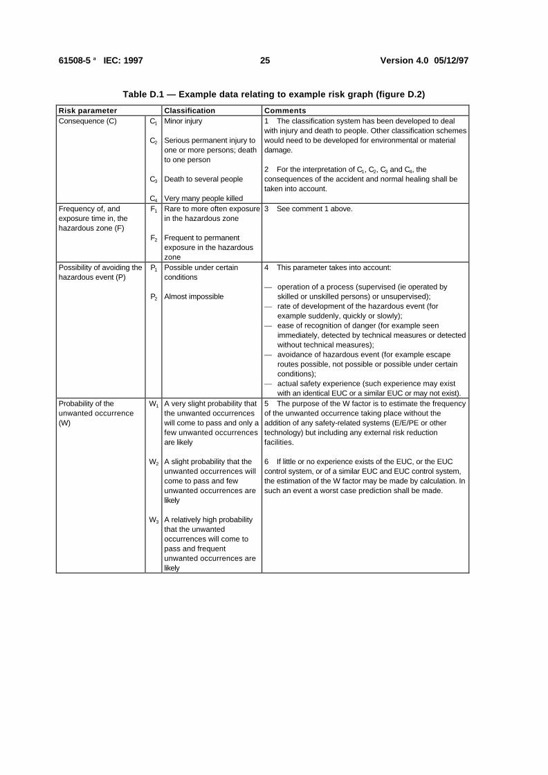
D.5 Risk graph example
An example of a risk graph implementation from the machinery sector, based on the example data in tableD.1, is shown in figure D.2. Use of the risk parameters C, F, and P lead to one of eight outputs. Each one ofthese outputs is mapped onto one of three scales (W1, W2 and W3). Each point on these scales (a, b, c, d,e, f, g and h) is an indication of the necessary risk reduction that has to be met by the safety-relatedsystem.
NOTE Further information on this risk graph implementation is given in reference [47] in annex C of part 1.

61508-5 IEC: 1997 24 Version 4.0 05/12/97
Starting point for risk reduction
estimation
a
b
1
1
2
2
23
3
34
4C = Consequence risk parameter
F = Frequency and exposure time risk parameter
P = Possibility of failing to avoid hazard risk parameter
W = Probability of the unwanted occurrence
a
a
1
--- ---
---
--- = No safety requirements
a = No special safety requirements
b = A single E/E/PES is not sufficient
1, 2, 3, 4 = Safety integrity level
W W W123C
C
C
C
F
F
P
P
P
A
B
D
C
A
B
FF
P
P
PA
B A
B
A
B
B
A
A
FF P
PA
B
B
X
X6
X5
X4
X3
X2
1
Generalized arrangement(in practical implementationsthe arrangement is specific to
the applications to be covered by the risk graph)
Figure D.1 — Risk graph: general scheme
a --b
c
d
e
f
g
h
F1
C1
P1
Starting point for risk reduction
estimationa, b, c, d, e, f, g, h represent the necessary minimum risk reduction. The link between the necessary minimum risk reduction and the safety integrity level is shown in the table.
W1W2
C = Consequence risk parameter
F = Frequency and exposure time riskparameter
P = Possibility of avoiding hazard riskparameter
W = Probability of the unwantedoccurrence
a, b, c ... h = Estimates of the required riskreduction for the SRSs
a
b
c
d
e
f
g
-a
b
c
d
e
f
Necessary minimum risk
reduction Safety integrity level
- No safety requirements
a No special safety requirements
b, c 1d 2
e, f 3g 4h An E/E/PE SRS is not
sufficient
W3
F2
F1
F2P2
P2
P1
C4
C3
C2
Figure D.2 — Risk graph: example (illustrates general principles only)
61508-5 IEC: 1997 25 Version 4.0 05/12/97
Table D.1 — Example data relating to example risk graph (figure D.2)
Risk parameter Classification Comments Consequence (C) C1
C2
C3
C4
Minor injury Serious permanent injury toone or more persons; deathto one person
Death to several people
Very many people killed
1 The classification system has been developed to dealwith injury and death to people. Other classification schemeswould need to be developed for environmental or materialdamage. 2 For the interpretation of C1, C2, C3 and C4, theconsequences of the accident and normal healing shall betaken into account.
Frequency of, andexposure time in, the hazardous zone (F)
F1
F2
Rare to more often exposurein the hazardous zone Frequent to permanentexposure in the hazardouszone
3 See comment 1 above.
Possibility of avoiding thehazardous event (P)
P1
P2
Possible under certainconditions Almost impossible
4 This parameter takes into account: — operation of a process (supervised (ie operated by
skilled or unskilled persons) or unsupervised);— rate of development of the hazardous event (for
example suddenly, quickly or slowly);— ease of recognition of danger (for example seen
immediately, detected by technical measures or detectedwithout technical measures);
— avoidance of hazardous event (for example escaperoutes possible, not possible or possible under certainconditions);
— actual safety experience (such experience may existwith an identical EUC or a similar EUC or may not exist).
Probability of theunwanted occurrence(W)
W1
W2
W3
A very slight probability thatthe unwanted occurrenceswill come to pass and only afew unwanted occurrencesare likely
A slight probability that theunwanted occurrences willcome to pass and fewunwanted occurrences arelikely
A relatively high probabilitythat the unwantedoccurrences will come topass and frequentunwanted occurrences arelikely
5 The purpose of the W factor is to estimate the frequencyof the unwanted occurrence taking place without theaddition of any safety-related systems (E/E/PE or othertechnology) but including any external risk reductionfacilities. 6 If little or no experience exists of the EUC, or the EUCcontrol system, or of a similar EUC and EUC control system,the estimation of the W factor may be made by calculation. Insuch an event a worst case prediction shall be made.

61508-5 IEC: 1997 26 Version 4.0 05/12/97
Annex E(informative)
Determination of safety integrity levels - a qualitative method:hazardous event severity matrix
E.1 General
The numeric method described in annex C is not applicable where the risk (or the frequency portion of it)cannot be quantified. This annex describes the hazardous event severity matrix method, which is aqualitative method that enables the safety integrity level of an E/E/PE safety-related system to bedetermined from a knowledge of the risk factors associated with the EUC and the EUC control system. It isparticularly applicable when the risk model is as indicated in figures A.1 and A.2.
The scheme outlined in this annex assumes that each safety-related system and external reduction facilityis independent.
This annex is not intended to be a definitive account of the method but is intended to illustrate the generalprinciples of how such a matrix could be developed by those having a detailed knowledge of the specificparameters that are relevant to its construction. Those intending to apply the methods indicated in thisannex should consult the source material referenced.
NOTE Further information on the hazardous event matrix is given in reference [48] in annex C of part 1.
E.2 Hazardous event severity matrix
The following requirements underpin the matrix and each one is necessary for the method to be valid:
a) the safety-related systems (E/E/PE and other technology) together with the external risk reductionfacilities are independent;
b) each safety-related system (E/E/PE and other technology) and external risk reduction facilities areconsidered as protection layers which provide, in their own right, partial risk reductions as indicated infigure A.1;
NOTE 1 This assumption is valid only if regular proof tests of the protection layers are carried out.
c) when one protection layer (see b) above) is added to the next one then one order of magnitudeimprovement in safety integrity is achieved;
NOTE 2 This assumption is valid only if the safety-related systems and external risk reduction facilities achieve anadequate level of independence.
d) only one E/E/PE safety-related system is used (but this may be in combination with an othertechnology safety-related system and/or external risk reduction facilities), for which this methodestablishes the necessary safety integrity level.
The above considerations lead to the hazardous event severity matrix shown in figure E.1. It should be notedthat the matrix has been populated with example data to illustrate the general principles. For each specificsituation, or sector comparable industries, a matrix similar to figure E.1 would be developed.

61508-5 IEC: 1997 27 Version 4.0 05/12/97
Hazardous event severity
[A] One SIL 3 E/E/PE safety-related system does not provide sufficient risk reduction at this risk level. Additional risk reduction measures are required.[B] One SIL 3 E/E/PE safety-related system may not provide sufficient risk reduction at this risk level. Hazard and risk analysis is required to determine whether additional risk reduction measures are necessary. [C] An independent E/E/PE safety-related system is probably not required.[D] Event likelihood is the likelihood that the hazardous event occurs without any safety related systems or external risk redution facilities. [E] SRS = safety-related system. Event likelihood and the total number of independent protection layers are defined in relation to the specific application.
Nu
mb
er o
f in
dep
end
ent
SR
Ss
and
ex
tern
al r
isk
red
uct
ion
fac
ilitie
s [E
] (i
nclu
ding
the
E/E
/PE
SR
S b
eing
cla
ssifi
ed)
Event likelihood [D]
Low Med High
SIL 1
SIL 1
SIL 1 SIL 2
Event likelihood [D]
Low Med High
SIL 1
SIL 2
SIL 2 SIL 3[B]
Event likelihood [D]
Low Med High
SIL 3[B]
SIL 3[B]
SIL 3[B]
SIL 3[A]
Minor
[C] [C] [C] [C] [C] [C] SIL 1 SIL 1
[C] [C] [C] SIL 1
3
1
2 SIL 1 SIL 2
[C]
Serious Extensive
Figure E.1 — Hazardous event severity matrix: example (illustrates general principles only)
Related Documents