The document was prepared using best effort. The authors make no warranty of any kind and shall not be liable in any event for incidental or consequential damages in connection with the application of the document. © All rights reserved. IEC 61508 Functional Safety Assessment Project: Mechanically actuated valves, direct operated solenoid valves, pneumatically operated valves and pilot operated solenoid valves Customer: HAFNER Pneumatika Kft. Halászi Hungary Contract Number: Q15/11-126-C Report No.: 15/11-126-C R003 Version V2, Revision R0, January 2020 Peter Söderblom

Welcome message from author
This document is posted to help you gain knowledge. Please leave a comment to let me know what you think about it! Share it to your friends and learn new things together.
Transcript

The document was prepared using best effort. The authors make no warranty of any kind and shall not be liable in any event for incidental or consequential damages in connection with the application of the document.
© All rights reserved.
IEC 61508 Functional Safety Assessment
Project:
Mechanically actuated valves, direct operated solenoid valves, pneumatically operated valves and pilot operated solenoid valves
Customer:
HAFNER Pneumatika Kft. Halászi Hungary
Contract Number: Q15/11-126-C
Report No.: 15/11-126-C R003
Version V2, Revision R0, January 2020
Peter Söderblom

© exida Hafner 1511-126-C R003 Assessment Report Solenoid valves V2R0.docx
T-023 V4R1 80 N. Main St, Sellersville, PA 18960 Page 2 of 41
Management Summary
This report summarizes the results of the functional safety assessment according to IEC 61508 carried out on the following products from HAFNER Pneumatika Kft.:
➢ Mechanically actuated valves
➢ Direct operated solenoid valves
➢ Pneumatically operated valves
➢ Pilot operated solenoid valves
Hereafter these are referred to as Solenoid valves in this report.
The functional safety assessment performed by exida consisted of the following activities:
- exida assessed the development process used by HAFNER Pneumatika Kft. through
an audit and review of a detailed safety case against the exida certification scheme which includes the relevant requirements of IEC 61508. The investigation was executed using subsets of the IEC 61508 requirements tailored to the work scope of the development team.
- exida performed a detailed Failure Modes, Effects, and Diagnostic Analysis (FMEDA) analysis of the device documenting the hardware architecture and failure behavior.
The functional safety assessment was performed to the requirements of IEC 61508:2010, SIL3
for mechanical components. A full IEC 61508 Safety Case was prepared using the exida Safety Case tool as the primary audit tool. Hardware process requirements and all associated documentation were reviewed. Environmental test reports were reviewed. Also the user documentation (safety manual) was reviewed.
The results of the Functional Safety Assessment can be summarized as:
The audited development process as tailored and implemented by the HAFNER Pneumatika Kft. Solenoid valves development project, complies with the relevant safety management requirements of IEC 61508:2010 SIL3, SC 3 (SIL3 Capable).
The assessment of the FMEDA, done to the requirements of IEC 61508, has shown that the Solenoid valves can be used in a low demand safety related system in a manor where the PFDavg is within the allowed range for up to SIL2 (HFT = 0) according to table 3 of IEC 61508-1.
The assessment of the FMEDA also shows that the Solenoid valves meet requirements for architectural constraints of an element such that it can be used to implement a SIL 2 safety function (with HFT = 0) or a SIL 3 safety function (with HFT = 1).
This means that the Solenoid valves are capable for use in SIL3 applications in Low DEMAND mode, when properly designed into a Safety Instrumented Function per the requirements in the Safety Manual and when using the versions specified in section 3.1 of this document.

© exida Hafner 1511-126-C R003 Assessment Report Solenoid valves V2R0.docx
T-023 V4R1 80 N. Main St, Sellersville, PA 18960 Page 3 of 41
The manufacturer will be entitled to use the Functional Safety Logo.

© exida Hafner 1511-126-C R003 Assessment Report Solenoid valves V2R0.docx
T-023 V4R1 80 N. Main St, Sellersville, PA 18960 Page 4 of 41
Table of Contents
Management Summary ................................................................................................... 2
1 Purpose and Scope ................................................................................................... 6
1.1 Tools and Methods used for the assessment ............................................................... 6
2 Project Management .................................................................................................. 7
2.1 exida ............................................................................................................................ 7
2.2 Roles of the parties involved ........................................................................................ 7
2.3 Standards and literature used ...................................................................................... 7
2.4 Reference documents .................................................................................................. 7
2.4.1 Documentation provided by HAFNER Pneumatika Kft. ...................................... 7
2.4.2 Documentation generated by exida ................................................................. 12
2.5 Assessment Approach ............................................................................................... 12
3 Product Description ................................................................................................. 14
3.1 Hardware Version Numbers ....................................................................................... 30
4 IEC 61508 Functional Safety Assessment Scheme................................................. 31
4.1 Methodology .............................................................................................................. 31
4.2 Assessment level ....................................................................................................... 31
5 Results of the IEC 61508 Functional Safety Assessment ........................................ 32
5.1 Lifecycle Activities and Fault Avoidance Measures .................................................... 32
5.1.1 Functional Safety Management ....................................................................... 32
5.1.2 Safety Requirements Specification and Architecture Design ............................ 33
5.1.3 Hardware Design ............................................................................................. 33
5.1.4 Validation ......................................................................................................... 33
5.1.5 Verification ....................................................................................................... 33
5.1.6 Modifications ................................................................................................... 33
5.1.7 User documentation......................................................................................... 34
5.2 Hardware Assessment ............................................................................................... 34
5.2.1 Failure rates .................................................................................................... 35
6 2019 IEC 61508 Functional Safety Surveillance Audit ............................................. 38
6.1 Roles of the parties involved ...................................................................................... 38
6.2 Surveillance Methodology .......................................................................................... 38
6.3 Surveillance Results ................................................................................................... 39
6.3.1 Procedure Changes ......................................................................................... 39
6.3.2 Engineering Changes ...................................................................................... 39
6.3.3 Impact Analysis ............................................................................................... 39
6.3.4 Field History .................................................................................................... 39
6.3.5 Safety Manual.................................................................................................. 39
6.3.6 FMEDA Update ............................................................................................... 39
6.3.7 Evaluate use of certificate and/or certification mark ......................................... 39
6.3.8 Previous Recommendations ............................................................................ 39
7 Terms and Definitions .............................................................................................. 40
8 Status of the Document ........................................................................................... 41
© exida Hafner 1511-126-C R003 Assessment Report Solenoid valves V2R0.docx
T-023 V4R1 80 N. Main St, Sellersville, PA 18960 Page 5 of 41
8.1 Liability ....................................................................................................................... 41
8.2 Releases .................................................................................................................... 41
8.3 Future Enhancements ................................................................................................ 41
8.4 Release Signatures .................................................................................................... 41

© exida Hafner 1511-126-C R003 Assessment Report Solenoid valves V2R0.docx
T-023 V4R1 80 N. Main St, Sellersville, PA 18960 Page 6 of 41
1 Purpose and Scope
This document shall describe the results of the IEC 61508 functional safety assessment of the following products from HAFNER Pneumatika Kft.:
➢ Mechanically actuated valves
➢ Direct operated solenoid valves
➢ Pneumatically operated valves
➢ Pilot operated solenoid valves
by exida according to accredited exida certification scheme which includes the requirements of IEC 61508:2010.
The assessment has been carried out based on the quality procedures and scope definitions of
exida
The results of this provides the safety instrumentation engineer with the required failure data as per IEC 61508 / IEC 61511 and confidence that sufficient attention has been given to systematic failures during the development process of the device.
1.1 Tools and Methods used for the assessment
This assessment was carried by using the exida Safety Case tool. The Safety Case tool
contains the exida scheme which includes all the relevant requirements of IEC 61508.
For the fulfillment of the objectives, expectations are defined which builds the acceptance level for the assessment. The expectations are reviewed to verify that each single requirement is covered. Because of this methodology, comparable assessments in multiple projects with different assessors are achieved. The arguments for the positive judgment of the assessor are documented within this tool and summarized within this report.
The assessment was planned by exida agreed with HAFNER Pneumatika Kft..
All assessment steps were continuously documented by exida (see [R1] and [R2]).

© exida Hafner 1511-126-C R003 Assessment Report Solenoid valves V2R0.docx
T-023 V4R1 80 N. Main St, Sellersville, PA 18960 Page 7 of 41
2 Project Management
2.1
exida is one of the world’s leading accredited Certification Bodies and knowledge companies specializing in automation system safety and availability with over 300 years of cumulative experience in functional safety. Founded by several of the world’s top reliability and safety
experts from assessment organizations and manufacturers, exida is a global company with
offices around the world. exida offers training, coaching, project oriented system consulting services, safety lifecycle engineering tools, detailed product assurance, cyber-security and
functional safety certification, and a collection of on-line safety and reliability resources. exida maintains a comprehensive failure rate and failure mode database on process equipment.
2.2 Roles of the parties involved
HAFNER Pneumatika Kft. Manufacturer of the Solenoid valves
exida Performed the hardware assessment
exida Performed the IEC 61508 Functional Safety Assessment.
HAFNER contracted exida in April 2016 for the IEC 61508 Functional Safety Assessment of the above mentioned device. The development audit was performed in Halászi, June 6 – 8 2016.
2.3 Standards and literature used
The services delivered by exida were performed based on the following standards / literature.
[N1] IEC 61508 (Parts 1 - 3): 2010 Functional Safety of Electrical/Electronic/Programmable Electronic Safety-Related Systems
2.4 Reference documents
Note: Documents revised after the 2016 audit are marked with * below.
2.4.1 Documentation provided by HAFNER Pneumatika Kft.
[D1]
Original filenames in Hungarian, please see Original Names.png.
MK Quality manual
[D2] ME-T3 Project management
[D3] FE-01-0001 Internal documentation registry
[D4] ME-01 Documentation management
[D5] ME-T7 Reclamation management
[D6] FE-T7-0007 Reclamation report
[D7] Fe-T7-0001 D8 report
[D8] ME-F3 Purchasing process
[D9] FE-F3-0002 Supplier selection data sheet
[D10] ME-01 Documentation management
[D11] ME-T3 Project management
[D12] ME-01 Documentation management

© exida Hafner 1511-126-C R003 Assessment Report Solenoid valves V2R0.docx
T-023 V4R1 80 N. Main St, Sellersville, PA 18960 Page 8 of 41
[D13] LU-T6-000 General test procedures
[D14] FE-T9-0007 Competence and responsibility matrix for the design department
[D15] FE-T9-0009 Training plan
[D16] FE-T9-0005 Training program
[D17] *ISO 9001:2015 certificate; N QMS-38784/h
[D18] FE-T3-0000 Customer request data sheet
[D19] FE-T3-0001 Feasibility checklist
[D20] Verification results: MH 311 704 Ex m
[D21] LU-T6-000 General test procedures
[D22] MN-54-01 Test report
[D23] ERP system: [email protected] V3.1. (Screenshot)
[D24] User manual; BTA-Namurflex
[D25] Safety manual V1 R1 of September 2016
[D26] BR 311 301 VES.pdf Mechanical drawing BR 311 301 VES of 2016.06.13
[D27] BR 311 301.pdf Mechanical drawing BR 311 301 of 2014.07.08
[D28] BR 511 301 VES.pdf Mechanical drawing BR 511 301 VES of 2016.07.06
[D29] BR 511 301.pdf Mechanical drawing BR 511 301 of 2014.03.31
[D30] M 311 704 VES Ex m.pdf Mechanical drawing M 311 704 VES Ex m of 2016.05.31
[D31] M 504 VES 01 EXM.pdf Mechanical drawing M 504 VES 01 EXM of 2016.05.31
[D32] MH 210 701 TT.pdf Mechanical drawing MH 210 701 TT of 2014.05.22
[D33] MH 210 701 VES.pdf Mechanical drawing MH 210 701 VES of 2016.07.06
[D34] MH 210 701.pdf Mechanical drawing MH 210 701 of 2012.10.24
[D35] MH 211 015 VES.pdf Mechanical drawing MH 211 015 VES of 2016.07.06
[D36] MH 211 015.pdf Mechanical drawing MH 211 015 of 2014.04.10
[D37] MH 211 701 TT.pdf Mechanical drawing MH 211 701 TT of 2016.07.06
[D38] MH 211 701 VES.pdf Mechanical drawing MH 211 701 VES of 2016.07.06
[D39] MH 211 701.pdf Mechanical drawing MH 211 701 of 2014.09.29
[D40] MH 310 701 TT.pdf Mechanical drawing MH 310 701 TT of 2013.10.04
[D41] MH 310 701 VES.pdf Mechanical drawing MH 310 701 VES of 2013.09.19
[D42] MH 310 701.pdf Mechanical drawing MH 310 701 of 2013.02.18
[D43] MH 311 015 TT.pdf Mechanical drawing MH 311 015 TT of 2013.08.28
[D44] MH 311 015 VES.pdf Mechanical drawing MH 311 015 VES of 2013.10.02
[D45] MH 311 015.pdf Mechanical drawing MH 311 015 of 2013.01.16
[D46] MH 311 701 TT.pdf Mechanical drawing MH 311 701 TT of 2013.03.06
[D47] MH 311 701 VES.pdf Mechanical drawing MH 311 701 VES of 2013.09.24

© exida Hafner 1511-126-C R003 Assessment Report Solenoid valves V2R0.docx
T-023 V4R1 80 N. Main St, Sellersville, PA 18960 Page 9 of 41
[D48] MH 311 701.pdf Mechanical drawing MH 311 701 of 2012.08.17
[D49] MH 311 704 VES Ex m.pdf
Mechanical drawing MH 311 704 VES Ex m of 2016.04.01
[D50] MH 320 704 VES Ex m.pdf
Mechanical drawing MH 320 704 VES Ex m of 2016.04.01
[D51] MH 501 TT.pdf Mechanical drawing MH 501 TT of 2013.09.13
[D52] MH 501 VES.pdf Mechanical drawing MH 501 VES of 2013.07.02
[D53] MH 501.pdf Mechanical drawing MH 501 of 2012.12.17
[D54] MH 504 VES 01 EXM.pdf Mechanical drawing MH 504 VES 01 EXM of 2016.04.01
[D55] MH 510 701 TT.pdf Mechanical drawing MH 510 701 TT of 2012.06.29
[D56] MH 510 701 VES.pdf Mechanical drawing MH 510 701 VES of 2013.04.30
[D57] MH 510 701.pdf Mechanical drawing MH 510 701 of 2013.02.12
[D58] MH 511 701 TT.pdf Mechanical drawing MH 511 701 TT of 2016.05.30
[D59] MH 511 701 VES.pdf Mechanical drawing MH 511 701 VES of 2013.09.18
[D60] MH 511 701.pdf Mechanical drawing MH 511 701 of 2014.01.10
[D61] MH 531 701 TT.pdf Mechanical drawing MH 531 701 TT of 2013.09.26
[D62] MH 531 701 VES.pdf Mechanical drawing MH 531 701 VES of 2013.09.18
[D63] MH 531 701.pdf Mechanical drawing MH 531 701 of 2012.11.09
[D64] P 310 701 TT.pdf Mechanical drawing P 310 701 TT of 2016.07.06
[D65] P 310 701 VES.pdf Mechanical drawing P 310 701 VES of 2013.02.25
[D66] P 310 701.pdf Mechanical drawing P 310 701 of 2014.01.17
[D67] P 311 701 TT.pdf Mechanical drawing P 311 701 TT of 2016.07.06
[D68] P 311 701 VES.pdf Mechanical drawing P 311 701 VES of 2013.02.25
[D69] P 311 701.pdf Mechanical drawing P 311 701 of 2014.11.28
[D70] P 501 01 VES.pdf Mechanical drawing P 501 01 VES of 2013.02.26
[D71] P 501 01.pdf Mechanical drawing P 501 01 of 2012.12.18
[D72] P 501 02.pdf Mechanical drawing P 501 02 of 2012.12.18
[D73] P 510 701 TT.pdf Mechanical drawing P 510 701 TT of 2014.05.22
[D74] P 510 701 VES.pdf Mechanical drawing P 510 701 VES of 2013.09.18
[D75] P 510 701.pdf Mechanical drawing P 510 701 of 2012.12.12
[D76] P 511 701 TT.pdf Mechanical drawing P 511 701 TT of 2016.07.06
[D77] P 511 701 VES.pdf Mechanical drawing P 511 701 VES of 2013.09.19
[D78] P 511 701.pdf Mechanical drawing P 511 701 of 2013.01.17
[D79] P 531 701 TT.pdf Mechanical drawing P 531 701 TT of 2016.07.06
[D80] P 531 701 VES.pdf Mechanical drawing P 531 701 VES of 2013.09.18
[D81] P 531 701.pdf Mechanical drawing P 531 701 of 2013.02.25

© exida Hafner 1511-126-C R003 Assessment Report Solenoid valves V2R0.docx
T-023 V4R1 80 N. Main St, Sellersville, PA 18960 Page 10 of 41
[D82] MH 532 701 TT.pdf Mechanical drawing MH 532 701 TT of 2016.08.11
[D83] MH 532 701 VES.pdf Mechanical drawing MH 532 701 VES of 2013.09.18
[D84] MH 532 701.pdf Mechanical drawing MH 532 701 of 2013.01.14
[D85] MH 533 701 TT.pdf Mechanical drawing MH 533 701 TT of 2016.08.11
[D86] MH 533 701 VES.pdf Mechanical drawing MH 533 701 VES of 2013.09.18
[D87] MH 533 701.pdf Mechanical drawing MH 533 701 of 2013.02.19
[D88] P 532 701 TT.pdf Mechanical drawing P 532 701 TT of 2016.08.11
[D89] P 532 701 VES.pdf Mechanical drawing P 532 701 VES of 2013.09.18
[D90] P 532 701.pdf Mechanical drawing P 532 701 of 2013.02.25
[D91] P 533 701 TT.pdf Mechanical drawing P 533 701 TT of 2015.11.11
[D92] P 533 701 VES.pdf Mechanical drawing P 533 701 VES of 2013.09.18
[D93] P 533 701.pdf Mechanical drawing P 533 701 of 2013.02.25
[D94] MNH 350 701.pdf Mechanical drawing MNH 350 701 of 2013.03.04
[D95] MNH 351 701.pdf Mechanical drawing MNH 351 701 of 2012.10.15
[D96] MH 310 121 TT AIR.pdf Mechanical drawing MH 310 121 TT AIR of 23.11.2018
[D97] MH 311 701 TT AIR.pdf Mechanical drawing MH 311 701 TT AIR of 23.11.2018
[D98] MH 510 121 TT AIR.pdf Mechanical drawing MH 510 121 TT AIR of 24.10.2018
[D99] MH 511 701 TT AIR.pdf Mechanical drawing MH 511 701 TT AIR of 14.09.2017
[D100] MH 531 701 TT AIR.pdf Mechanical drawing MH 531 701 TT AIR of 18.09.2017
[D101] MH 532 701 TT AIR.pdf Mechanical drawing MH 532 701 TT AIR of 23.11.2018
[D102] MH 533 701 TT AIR.pdf Mechanical drawing MH 533 701 TT AIR of 23.11.2018
[D103] P 310 121 TT AIR.pdf Mechanical drawing P 310 121 TT AIR of 23.11.2018
[D104] P 311 701 TT AIR.pdf Mechanical drawing P 311 701 TT AIR of 23.11.2018
[D105] P 510 121 TT AIR.pdf Mechanical drawing P 510 121 TT AIR of 23.11.2018
[D106] P 511 701 TT AIR.pdf Mechanical drawing P 511 701 TT AIR of 23.11.2018
[D107] P 531 701 TT AIR.pdf Mechanical drawing P 531 701 TT AIR of 23.11.2018
[D108] P 532 701 TT AIR.pdf Mechanical drawing P 532 701 TT AIR of 23.11.2018
[D109] P 533 701 TT AIR.pdf Mechanical drawing P 533 701 TT AIR of 23.11.2018
[D110] MEH 211 701 TT.pdf Mechanical drawing MEH 211 701 TT of 26.11.2018
[D111] MEH 211 701 VES.pdf Mechanical drawing MEH 211 701 VES of 26.11.2018
[D112] MEH 211 701.pdf Mechanical drawing MEH 211 701 of 26.11.2018
[D113] MEH 311 701 TT AIR.pdf Mechanical drawing MEH 311 701 TT AIR of 26.11.2018
[D114] MEH 311 701 TT.pdf Mechanical drawing MEH 311 701 TT of 26.11.2018
[D115] MEH 311 701 VES.pdf Mechanical drawing MEH 311 701 VES of 26.11.2018
[D116] MEH 311 701.pdf Mechanical drawing MEH 311 701 of 19.02.2013

© exida Hafner 1511-126-C R003 Assessment Report Solenoid valves V2R0.docx
T-023 V4R1 80 N. Main St, Sellersville, PA 18960 Page 11 of 41
[D117] MEH 511 701 TT AIR.pdf Mechanical drawing MEH 511 701 TT AIR of 26.11.2018
[D118] MEH 511 701 TT.pdf Mechanical drawing MEH 511 701 TT of 23.01.2013
[D119] MEH 511 701 VES.pdf Mechanical drawing MEH 511 701 VES of 26.11.2018
[D120] MEH 511 701.pdf Mechanical drawing MEH 511 701 of 23.01.2013
[D121] MEH 531 701 TT AIR.pdf Mechanical drawing MEH 531 701 TT AIR of 26.11.2018
[D122] MEH 531 701 TT.pdf Mechanical drawing MEH 531 701 TT of 26.11.2018
[D123] MEH 531 701 VES.pdf Mechanical drawing MEH 531 701 VES of 26.11.2018
[D124] MEH 531 701.pdf Mechanical drawing MEH 531 701 of 08.11.2013
[D125] MEH 532 701 TT AIR.pdf Mechanical drawing MEH 532 701 TT AIR of 26.11.2018
[D126] MEH 532 701 TT.pdf Mechanical drawing MEH 532 701 TT of 26.11.2018
[D127] MEH 532 701 VES.pdf Mechanical drawing MEH 532 701 VES of 26.11.2018
[D128] MEH 532 701.pdf Mechanical drawing MEH 532 701 of 26.11.2018
[D129] MEH 533 701 TT AIR.pdf Mechanical drawing MEH 533 701 TT AIR of 26.11.2018
[D130] MEH 533 701 TT.pdf Mechanical drawing MEH 533 701 TT of 26.11.2018
[D131] MEH 533 701 VES.pdf Mechanical drawing MEH 533 701 VES of 26.11.2018
[D132] MEH 533 701.pdf Mechanical drawing MEH 533 701 of 26.11.2018
[D133] MEH 501 TT.pdf Mechanical drawing MEH 501 TT of 26.11.2018
[D134] MEH 501 VES.pdf Mechanical drawing MEH 501 VES of 03.02.2017
[D135] MEH 501.pdf Mechanical drawing MEH 501 of 15.02.2013
[D136] MH 121 TT.pdf Mechanical drawing MH 121 TT of 06.09.2013
[D137] MH 501 TT.pdf Mechanical drawing MH 501 TT of 13.09.2013
[D138] P 121 01.pdf Mechanical drawing P 121 01 of 18.12.2012
[D139] ZD MH 501 TT AIR.pdf Mechanical drawing ZD MH 501 TT AIR of 24.08.2017
[D140] ZD MH 530 TT AIR.pdf Mechanical drawing ZD MH 530 TT AIR of 23.11.2017
[D141] HAFNER Ventilgruppen - 2018.11.23..xlsx
[D142] * MH 311 209 - 24DC - FE-T3-0001.pdf
Development order close for MH 311 209 - 24DC of 2016-05-24
[D143] * MH 311 209 - 24DC - FE-T3-0004.pdf
Verification report for MH 311 209 - 24DC of 2016-05-24
[D144] * MH 510 121 TT AIR - FE-T3-0001.pdf
Development order close for MH 510 121 TT AIR of 2017-05-12
[D145] * MH 510 121 TT AIR - FE-T3-0004.pdf
Verification report for MH 510 121 TT AIR of 2017-05-12
[D146] * Testbericht MH 520 701 TT AIR-24DC_20170526
Test report MH 510 121 TT AR – 24 VDC
[D147] *Nr. 649 - 20161103 - REKLAMATIONSBERICHT.pdf
Field return report
© exida Hafner 1511-126-C R003 Assessment Report Solenoid valves V2R0.docx
T-023 V4R1 80 N. Main St, Sellersville, PA 18960 Page 12 of 41
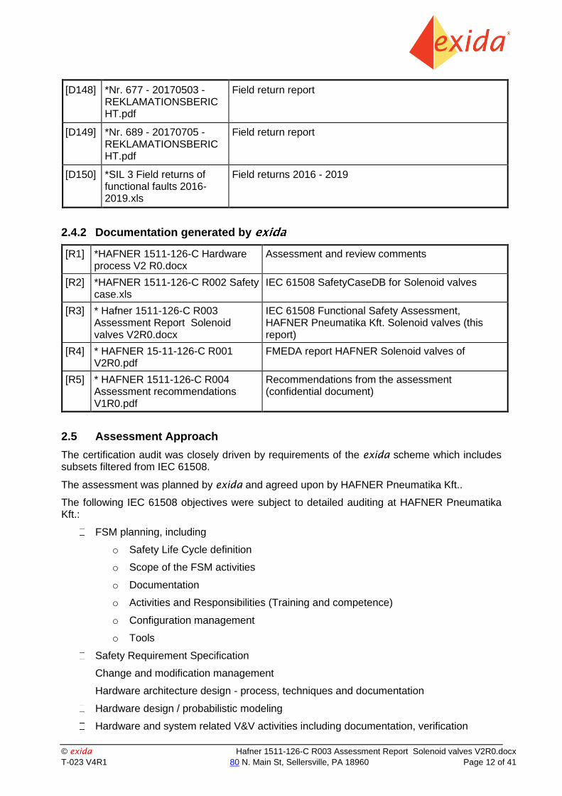
[D148] *Nr. 677 - 20170503 - REKLAMATIONSBERICHT.pdf
Field return report
[D149] *Nr. 689 - 20170705 - REKLAMATIONSBERICHT.pdf
Field return report
[D150] *SIL 3 Field returns of functional faults 2016-2019.xls
Field returns 2016 - 2019
2.4.2 Documentation generated by
[R1] *HAFNER 1511-126-C Hardware process V2 R0.docx
Assessment and review comments
[R2] *HAFNER 1511-126-C R002 Safety case.xls
IEC 61508 SafetyCaseDB for Solenoid valves
[R3] * Hafner 1511-126-C R003 Assessment Report Solenoid valves V2R0.docx
IEC 61508 Functional Safety Assessment, HAFNER Pneumatika Kft. Solenoid valves (this report)
[R4] * HAFNER 15-11-126-C R001 V2R0.pdf
FMEDA report HAFNER Solenoid valves of
[R5] * HAFNER 1511-126-C R004 Assessment recommendations V1R0.pdf
Recommendations from the assessment (confidential document)
2.5 Assessment Approach
The certification audit was closely driven by requirements of the exida scheme which includes subsets filtered from IEC 61508.
The assessment was planned by exida and agreed upon by HAFNER Pneumatika Kft..
The following IEC 61508 objectives were subject to detailed auditing at HAFNER Pneumatika Kft.:
FSM planning, including
o Safety Life Cycle definition
o Scope of the FSM activities
o Documentation
o Activities and Responsibilities (Training and competence)
o Configuration management
o Tools
Safety Requirement Specification
Change and modification management
Hardware architecture design - process, techniques and documentation
Hardware design / probabilistic modeling
Hardware and system related V&V activities including documentation, verification

© exida Hafner 1511-126-C R003 Assessment Report Solenoid valves V2R0.docx
T-023 V4R1 80 N. Main St, Sellersville, PA 18960 Page 13 of 41
o Fault insertion test strategy
System / hardware validation
Hardware-related operation, installation and maintenance requirements

© exida Hafner 1511-126-C R003 Assessment Report Solenoid valves V2R0.docx
T-023 V4R1 80 N. Main St, Sellersville, PA 18960 Page 14 of 41
3 Product Description
The mechanically actuated valves, direct operated solenoid valves, pneumatically operated valves and pilot operated solenoid valves can be considered to be part of a Type A element with a hardware fault tolerance of 0.
Table 1 gives an overview of the different variants that belong to the considered mechanically actuated valves, direct operated solenoid valves, pneumatically operated valves and pilot operated solenoid valves.
For safety applications only the described variants in Table 1 of the mechanically actuated valves, direct operated solenoid valves, pneumatically operated valves and pilot operated solenoid valves working as DTT (De-energize To Trip) devices have been considered.
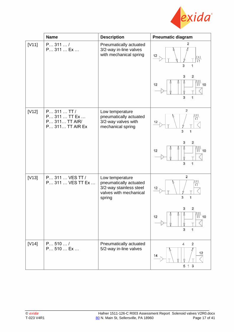
Table 1: Variants overview
Name Description Pneumatic diagram
[V1] BR 311 … Mechanically actuated 3/2-way roller lever valves
[V2] BR 311 … VES Mechanically actuated stainless steel 3/2-way roller lever valves
[V3] BR 511 … Mechanically actuated 5/2-way roller lever valves
[V4] BR 511 … VES Mechanically actuated stainless steel 5/2-way roller lever valves

© exida Hafner 1511-126-C R003 Assessment Report Solenoid valves V2R0.docx
T-023 V4R1 80 N. Main St, Sellersville, PA 18960 Page 15 of 41
Name Description Pneumatic diagram
[V5] M… 211 … / M… 211 … Ex …
M… 311 … / M… 311 … Ex … / M… 311 … TT / M… 311 … TT Ex …
Direct actuated in-line 2/2-way or 3/2-way solenoid valves
[V6] M… 211 … VES / M… 211 … VES Ex …
M… 311 … VES / M… 311 … VES TT / M… 311 … VES Ex … / M… 311 … VES TT Ex …
Direct actuated in-line 2/2-way or 3/2-way stainless steel solenoid valves
[V7] P… 310 … / P… 310 … Ex …
Pneumatically actuated 3/2-way in-line valves

© exida Hafner 1511-126-C R003 Assessment Report Solenoid valves V2R0.docx
T-023 V4R1 80 N. Main St, Sellersville, PA 18960 Page 16 of 41
Name Description Pneumatic diagram
[V8] P… 310 … VES / P… 310 … VES Ex … P… 311 … VES / P… 311 … VES Ex …
Pneumatically actuated 3/2-way in-line stainless steel valves without and with mechanical spring
[V9] [V9b]
P… 310 … TT P… 310 … TT Ex … P… 310… TT AIR/ P… 310… TT AIR Ex
Low temperature pneumatically actuated 3/2-way valves
[V10] P… 310 … VES TT / P… 310 … VES TT Ex …
Low temperature pneumatically actuated 3/2-way stainless steel valves
© exida Hafner 1511-126-C R003 Assessment Report Solenoid valves V2R0.docx
T-023 V4R1 80 N. Main St, Sellersville, PA 18960 Page 17 of 41
Name Description Pneumatic diagram
[V11] P… 311 … / P… 311 … Ex …
Pneumatically actuated 3/2-way in-line valves with mechanical spring
[V12] P… 311 … TT / P… 311 … TT Ex … P… 311… TT AIR/ P… 311… TT AIR Ex
Low temperature pneumatically actuated 3/2-way valves with mechanical spring
[V13] P… 311 … VES TT / P… 311 … VES TT Ex …
Low temperature pneumatically actuated 3/2-way stainless steel valves with mechanical spring
[V14] P… 510 … / P… 510 … Ex …
Pneumatically actuated 5/2-way in-line valves

© exida Hafner 1511-126-C R003 Assessment Report Solenoid valves V2R0.docx
T-023 V4R1 80 N. Main St, Sellersville, PA 18960 Page 18 of 41
Name Description Pneumatic diagram
[V15] P… 510 … VES / P… 510 … VES Ex … P… 511 … VES / P… 511 … VES Ex …
Pneumatically actuated 5/2-way in-line stainless steel valves
[V16] P… 510 … TT / P… 510 … TT Ex … P… 510… TT AIR/ P… 510… TT AIR Ex
Low temperature pneumatically actuated 5/2-way valves
[V17] P… 510 … VES TT / P… 510 … VES TT Ex …
Low temperature pneumatically actuated 5/2-way stainless steel valves
[V18] P… 511 … / P… 511 … Ex …
Pneumatically actuated 5/2-way in-line valves with mechanical spring
[V19] P… 511 … TT / P… 511 … TT Ex … P… 511… TT AIR/ P… 511… TT AIR Ex
Low temperature pneumatically actuated 5/2-way valves with mechanical spring
© exida Hafner 1511-126-C R003 Assessment Report Solenoid valves V2R0.docx
T-023 V4R1 80 N. Main St, Sellersville, PA 18960 Page 19 of 41
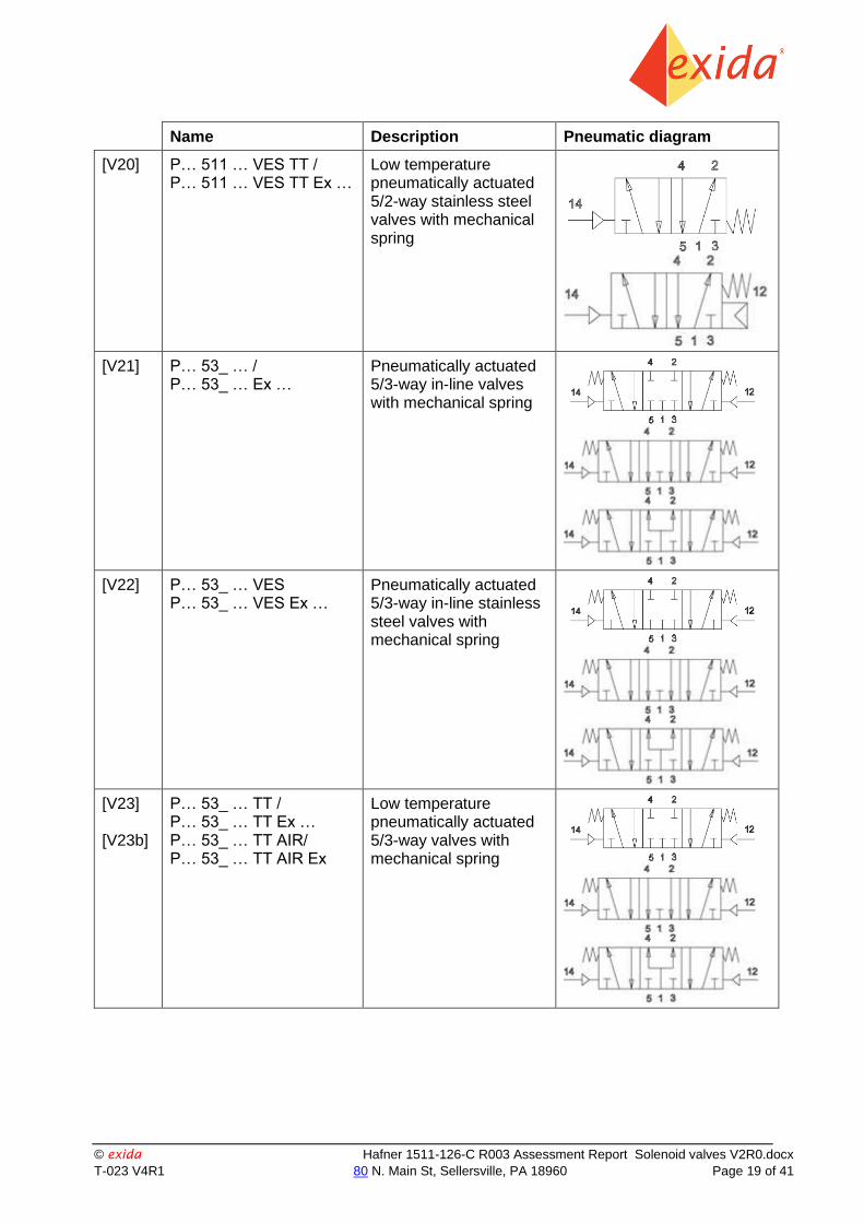
Name Description Pneumatic diagram
[V20] P… 511 … VES TT / P… 511 … VES TT Ex …
Low temperature pneumatically actuated 5/2-way stainless steel valves with mechanical spring
[V21] P… 53_ … / P… 53_ … Ex …
Pneumatically actuated 5/3-way in-line valves with mechanical spring
[V22] P… 53_ … VES P… 53_ … VES Ex …
Pneumatically actuated 5/3-way in-line stainless steel valves with mechanical spring
[V23] [V23b]
P… 53_ … TT / P… 53_ … TT Ex … P… 53_ … TT AIR/ P… 53_ … TT AIR Ex
Low temperature pneumatically actuated 5/3-way valves with mechanical spring

© exida Hafner 1511-126-C R003 Assessment Report Solenoid valves V2R0.docx
T-023 V4R1 80 N. Main St, Sellersville, PA 18960 Page 20 of 41
Name Description Pneumatic diagram
[V24] P… 53_ … VES TT / P… 53_ … VES TT Ex …
Low temperature pneumatically actuated 5/3-way stainless steel valves with mechanical spring
[V25] M… 210 … / M… 210 … Ex … M… 211 … / M… 211 … Ex …
Pilot operated 2/2-way in-line solenoid valves
[V26] M… 210 … VES / M… 210 … VES Ex … M… 211 … VES / M… 211 … VES Ex …
Pilot operated 2/2-way in-line stainless steel solenoid valves
[V27] M… 210 … TT / M… 210 … TT Ex … M… 211 … TT / M… 211 … TT Ex …
Low temperature pilot operated 2/2-way in-line solenoid valves
[V28] M… 210 … VES TT / M… 210 … VES TT Ex … M… 211 … VES TT / M… 211 … VES TT Ex …
Low temperature pilot operated 2/2-way in-line stainless steel solenoid valves

© exida Hafner 1511-126-C R003 Assessment Report Solenoid valves V2R0.docx
T-023 V4R1 80 N. Main St, Sellersville, PA 18960 Page 21 of 41
Name Description Pneumatic diagram
[V29] M… 310 … / M… 310 … Ex … M… 311 … / M… 311 … Ex …
Pilot operated in-line 3/2-way solenoid valves
[V30] M… 310 … VES / M… 310 … VES Ex … M… 311 … VES / M… 311 … VES Ex …
Pilot operated in-line 3/2-way stainless steel solenoid valves
[V31] [V31b]
M… 310 … TT / M… 310 … TT Ex … M… 311 … TT / M… 311 … TT Ex … M… 310 … TT AIR/ M… 310 … TT AIR Ex M… 311 … TT AIR/ M… 311 … TT AIR Ex
Pilot operated low temperature in-line 3/2-way solenoid valves

© exida Hafner 1511-126-C R003 Assessment Report Solenoid valves V2R0.docx
T-023 V4R1 80 N. Main St, Sellersville, PA 18960 Page 22 of 41
Name Description Pneumatic diagram
[V32] M… 310 … VES TT / M… 310 … VES TT Ex … M… 311 … VES TT / M… 311 … VES TT Ex …
Pilot operated low temperature in-line 3/2-way stainless steel solenoid valves
[V33] M… 510 … / M… 510 … Ex … M… 511 … / M… 511 … Ex …
M… 350 … / M… 350 … Ex … M… 351 … / M… 351 … Ex …
Pilot operated in-line 5/2-way solenoid valves
[V34] M… 510 … VES / M… 510 … VES Ex … M… 511 … VES / M… 511 … VES Ex …
M… 350 … VES / M… 350 … VES Ex … M… 351 … VES / M… 351 … VES Ex …
Pilot operated in-line 5/2-way stainless steel solenoid valves

© exida Hafner 1511-126-C R003 Assessment Report Solenoid valves V2R0.docx
T-023 V4R1 80 N. Main St, Sellersville, PA 18960 Page 23 of 41
Name Description Pneumatic diagram
[V35] M… 510 … TT / M… 510 … TT Ex … M… 510 … TT AIR/ M… 510 … TT AIR Ex
M… 350 … TT / M… 350 … TT Ex …
Pilot operated low temperature in-line 5/2-way solenoid valves
[V36] M… 510 … VES TT / M… 510 … VES TT Ex …
M… 350 … VES TT / M… 350 … VES TT Ex …
Pilot operated low temperature in-line 5/2-way stainless steel solenoid valves
[V37]
[V37b]
M… 511 … TT / M… 511 … TT Ex …
M… 351 … TT / M… 351 … TT Ex …
M… 511 … TT AIR/ M… 511 … TT AIR Ex
Pilot operated low temperature in-line 5/2-way solenoid valves with mechanical spring
[V38] M… 511 … VES TT / M… 511 … VES TT Ex …
M… 351 … VES TT / M… 351 … VES TT Ex …
Pilot operated low temperature in-line 5/2-way stainless steel solenoid valves with mechanical spring
[V39] M… 53_ … / M… 53_ … Ex …
Pilot operated in-line 5/3-way solenoid valves

© exida Hafner 1511-126-C R003 Assessment Report Solenoid valves V2R0.docx
T-023 V4R1 80 N. Main St, Sellersville, PA 18960 Page 24 of 41
Name Description Pneumatic diagram
[V40] M… 53_ … VES / M… 53_ … VES Ex …
Pilot operated in-line 5/3-way stainless steel solenoid valves
[V41] [V41b]
M… 53_ … TT / M… 53_ … TT Ex … M… 53_ … TT AIR/ M… 53_ … TT AIR Ex
Pilot operated low temperature in-line 5/3-way solenoid valves
[V42] M… 53_ … VES TT / M… 53_ … VES TT Ex …
Pilot operated low temperature in-line 5/3-way stainless steel solenoid valves
[V43] ME. 211…/ ME. 211… Ex
ME. 311…/ ME. 311… Ex
External pilot feed operated 2/2-way or 3/2 way in-line solenoid valves

© exida Hafner 1511-126-C R003 Assessment Report Solenoid valves V2R0.docx
T-023 V4R1 80 N. Main St, Sellersville, PA 18960 Page 25 of 41
Name Description Pneumatic diagram
[V44] ME. 211… VES/ ME. 211… VES Ex
ME. 311… VES/ ME. 311… VES Ex
External pilot feed operated 2/2-way or 3/2 way in-line stainless steel solenoid valves
[V45] ME. 211… TT/ ME. 211… TT Ex
ME. 311… TT/ ME. 311… TT Ex/
Low temperature external pilot feed operated 2/2-way or 3/2 way in-line solenoid valves
[V46] ME. 211… VES TT/ ME. 211… VES TT Ex
ME. 311… VES TT/ ME. 311… VES TT Ex
Low temperature external pilot feed operated 2/2-way or 3/2 way in-line stainless steel solenoid valves
[V47] ME. 311… TT AIR/ ME. 311… TT AIR Ex
Low temperature external pilot feed operated 3/2-way in-line solenoid valves
[V48] ME. 511…/ ME. 511… Ex
External pilot feed operated 5/2-way in-line solenoid valves
[V49] ME. 511… VES/ ME. 511… VES Ex
External pilot feed operated 5/2-way in-line stainless steel solenoid valves
[V50] ME. 511… TT/ ME. 511… TT Ex
Low temperature external pilot feed operated 5/2-way in-line solenoid valves

© exida Hafner 1511-126-C R003 Assessment Report Solenoid valves V2R0.docx
T-023 V4R1 80 N. Main St, Sellersville, PA 18960 Page 26 of 41
Name Description Pneumatic diagram
[V51] ME. 511… VES TT/ ME. 511… VES TT Ex
Low temperature external pilot feed operated 5/3-way in-line stainless steel solenoid valves
[V52] ME. 511… TT AIR/ ME. 511… TT AIR Ex
Low temperature external pilot feed operated 5/2-way in-line solenoid valves
[V53] ME. 53_…/ ME. 53_… Ex
External pilot feed operated 5/3-way in-line solenoid valves
[V54] ME. 53_… VES/ ME. 53_… VES Ex
External pilot feed
operated 5/3-way in-
line stainless steel
solenoid valves
[V55] ME. 53_… TT/ ME. 53_… TT Ex
Low temperature external pilot feed operated 5/3-way in-line solenoid valves

© exida Hafner 1511-126-C R003 Assessment Report Solenoid valves V2R0.docx
T-023 V4R1 80 N. Main St, Sellersville, PA 18960 Page 27 of 41
Name Description Pneumatic diagram
[V56] ME. 53_… VES TT/ ME. 53_… VES TT Ex
Low temperature external pilot feed operated 5/3-way in-line stainless steel solenoid valves
[V57] ME. 53_… TT AIR ME. 53_… TT AIR Ex
Low temperature external pilot feed operated 5/3-way in-line solenoid valves
A number of logic-elements, bi-stable and quick-exhaust variants were also subject of the assessment for Systematic Capability. As they share the same development process, verification and testing as the Variants listed above in Table 1, the Logic-elements, bi-stable and quick-exhaust variants meet the same requirements for Systematic Capability as the variants [V1] – [V57] listed above. However, these Logic-elements, bi-stable and quick-exhaust variants are not generally suitable for safety applications so no FMEDA analysis was done for them.
Table 2 gives an overview of the Logic-elements, bi-stable and quick-exhaust variants which were only evaluated for their Systematic Capability.
Table 2: Logic-elements, bi-stable and quick-exhaust variants overview
Name Description Pneumatic diagram
[BV1] ES …
ES … Ex …
Logic elements
AND-Gates
[BV2] ES … TT
ES … TT Ex …
Low temperature
logic elements
AND-Gates

© exida Hafner 1511-126-C R003 Assessment Report Solenoid valves V2R0.docx
T-023 V4R1 80 N. Main St, Sellersville, PA 18960 Page 28 of 41
Name Description Pneumatic diagram
[BV3] ES … VES
ES … VES Ex …
Stainless steel
logic elements
AND-Gates
[BV4] ES … VES TT
ES … VES TT Ex …
Stainless steel
low temperature
logic elements
AND-Gates
[BV5] VA …
VA … Ex …
Stainless steel
low temperature
logic elements
OR-Gates
[BV6] VA … TT
VA … TT Ex …
Low temperature
logic elements
OR-Gates
[BV7] VA … VES
VA … VES Ex …
Stainless steel
logic elements
OR-Gates
[BV8] VA … VES TT
VA … VES TT Ex …
Stainless steel
low temperature
logic elements
OR-Gates
[BV9] SE …
SE … Ex …
Quick exhaust valves
[BV10] SE … TT
SE … TT Ex …
Low temperature
quick exhaust valves
[BV11] SE … VES
SE … VES Ex …
Stainless steel
quick exhaust valves
[BV12] SE … VES TT
SE … VES TT Ex …
Stainless steel
low temperature
quick exhaust valves

© exida Hafner 1511-126-C R003 Assessment Report Solenoid valves V2R0.docx
T-023 V4R1 80 N. Main St, Sellersville, PA 18960 Page 29 of 41
Name Description Pneumatic diagram
[BV13] M … 320 …
M … 320 … Ex …
Pilot operated in-line
3/2-way bistable
solenoid valves
[BV14] M … 320 … TT
M … 320 … TT Ex …
Low temperature
pilot operated in-line
3/2-way bistable
solenoid valves
[BV15] M … 320 … VES
M … 320 … VES Ex …
M … 320 … VES TT
M … 320 … VES TT Ex …
Stainless steel and
low temperature stainless steel
pilot operated in-line
3/2-way bistable
solenoid valves
[BV16] M … 520 …
M … 520 … Ex …
Pilot operated in-line
5/2-way bistable
solenoid valves
[BV17] M … 520 … TT
M … 520 … TT Ex …
Low temperature
pilot operated in-line
5/2-way bistable
solenoid valves
[BV18] M … 520 … VES
M … 520 … VES Ex …
M … 520 … VES TT
M … 520 … VES TT Ex …
Stainless steel and
low temperature stainless steel
pilot operated in-line
5/2-way bistable
solenoid valves
[BV19] P … 320 …
P … 320 … Ex …
Pneumatically actuated in-line
3/2-way bistable valves
[BV20] P … 320 … TT
P … 320 … TT Ex …
Low temperature
pneumatically actuated in-line
3/2-way bistable valves
[BV21] P … 320 … VES
P … 320 … VES Ex …
P … 320 … VES TT
P … 320 … VES TT Ex …
Stainless steel and
low temperature stainless steel
pneumatically actuated in-line
3/2-way bistable valves

© exida Hafner 1511-126-C R003 Assessment Report Solenoid valves V2R0.docx
T-023 V4R1 80 N. Main St, Sellersville, PA 18960 Page 30 of 41
Name Description Pneumatic diagram
[BV22] P … 520 …
P … 520 … Ex …
Pneumatically actuated in-line
5/2-way bistable valves
[BV23] P … 520 … TT
P … 520 … TT Ex …
Low temperature
pneumatically actuated in-line
5/2-way bistable valves
[BV24] P … 520 … VES
P … 520 … VES Ex …
P … 520 … VES TT
P … 520 … VES TT Ex …
Stainless steel and
low temperature stainless steel
pneumatically actuated in-line
5/2-way bistable valves
3.1 Hardware Version Numbers
This assessment is applicable to the hardware versions of the Solenoid valves as documented in the corresponding drawing – see [D26] – [D141] for details.

© exida Hafner 1511-126-C R003 Assessment Report Solenoid valves V2R0.docx
T-023 V4R1 80 N. Main St, Sellersville, PA 18960 Page 31 of 41
4 IEC 61508 Functional Safety Assessment Scheme
exida assessed the development process used by HAFNER Pneumatika Kft. for this
development project against the objectives of the exida certification scheme which includes subsets of IEC 61508 -1 and 2. The results of the assessment are documented in [R1] to [R5].
4.1 Methodology
The full functional safety assessment includes an assessment of all fault avoidance and fault control measures during hardware development and demonstrates full compliance with IEC 61508 to the end-user. The assessment considers all requirements of IEC 61508. Any requirements that have been deemed not applicable have been marked as such in the full Safety Case report, e.g. software development requirements for a product with no software. The assessment also includes a review of existing manufacturing quality procedures to ensure compliance to the quality requirements of IEC 61508.
As part of the IEC 61508 functional safety assessment the following aspects have been reviewed:
Development process, including:
o Functional Safety Management, including training and competence recording, FSM planning, and configuration management
o Specification process, techniques and documentation
o Design process, techniques and documentation, including tools used
o Validation activities, including development test procedures, test plans and reports, production test procedures and documentation
o Verification activities and documentation
o Modification process and documentation
o Installation, operation, and maintenance requirements, including user documentation
Product design
o Hardware architecture and failure behavior, documented a FMEDA
The review of the development procedures is described in section 5. The review of the product design is described in section 5.2.
4.2 Assessment level
The Solenoid valves has been assessed per IEC 61508 to the following level:
SIL 3 capability
The development procedures have been assessed as suitable for use in applications with a maximum Safety Integrity Level of 3 (SIL3) according to IEC 61508.

© exida Hafner 1511-126-C R003 Assessment Report Solenoid valves V2R0.docx
T-023 V4R1 80 N. Main St, Sellersville, PA 18960 Page 32 of 41
5 Results of the IEC 61508 Functional Safety Assessment
exida assessed the development process used by HAFNER Pneumatika Kft. for these products against the objectives of IEC 61508 parts 1 - 3.
The assessment was done in June - November 2016 and documented in the SafetyCase [R2]. The surveillance audit was done in October 2019.
5.1 Lifecycle Activities and Fault Avoidance Measures
HAFNER Pneumatika Kft. have a defined product lifecycle process in place. This is documented in the Quality Manual [D1] and the referenced documents therein. A documented modification process is also covered in the Quality Manual. No software is part of the design and therefore any requirements specific from IEC 61508 to software and software development do not apply.
The assessment investigated the compliance with IEC 61508 of the processes, procedures and techniques as implemented for product design and development. The investigation was executed using subsets of the IEC 61508 requirements tailored to the SIL 3 work scope of the development team. The result of the assessment can be summarized by the following observations:
The audited HAFNER Pneumatika Kft. design and development process complies with the relevant managerial requirements of IEC 61508 SIL 3.
5.1.1 Functional Safety Management
FSM Planning
HAFNER Pneumatika Kft. have a defined process in place for product design and development. Required activities are specified along with review and approval requirements. The different phases together with the corresponding work items and their required input and output is defined. It also contains references to other planning documents where the verification and validation activities and methods are defined. The roles and responsibilities are also defined herein.
Sample documents have been reviewed and found to be sufficient. The modification process is covered by the Quality manual [D1]. This process and the procedures referenced therein fulfill the requirements of IEC 61508 with respect to functional safety management for a product with simple complexity and well defined safety functionality.
Version Control
The Quality manual [D1] requires that all documents and drawings are under version control. They are stored in the ERP system with full version management. All of the server discs also have daily backups and it’s simple to restore a file from one of the backups as shown in the audit.
Which versions of a work product was part of which test run is documented in the respective test report [D22].
Training, Competency recording
In the personal profile, kept at the HR department, the different training courses / seminars of each individual together with the official education are documented. Given that the development department is small; all projects always have access to the developers which have a long experience from similar projects at HAFNER Pneumatika Kft..

© exida Hafner 1511-126-C R003 Assessment Report Solenoid valves V2R0.docx
T-023 V4R1 80 N. Main St, Sellersville, PA 18960 Page 33 of 41
5.1.2 Safety Requirements Specification and Architecture Design
The requirements for the Solenoid valves are based on the customer or in-house requirements [D18] which includes the safety related requirements. As the design is simple and based upon standard designs with extensive field history, no semi-formal methods are needed. General Design and testing methodology is documented and required as part of the design process. This meets SIL 3.
5.1.3 Hardware Design
The design process is documented in the Quality manual [D1]. Items from IEC 61508-2, Table B.2 include observance of guidelines and standards, project management, documentation (design outputs are documented per quality procedures), structured design, modularization, use of well-tried components computer-aided design tools. This meets SIL 3.
5.1.4 Validation
Validation Testing is documented in the General test procedures [D1]. The test plan includes testing per all standard and customer performance requirements. As the Solenoid valves are purely mechanical devices with a simple safety function, there is no separate integration testing necessary. The Solenoid valves perform only 1 Safety Function, which is extensively tested under various conditions during validation testing.
Items from IEC 61508-2, Table B.3 include functional testing, project management, documentation, and black-box testing (for the considered devices this is similar to functional testing). Field experience and statistical testing via regression testing are not applicable. This meets SIL 3.
Items from IEC 61508-2, Table B.5 included functional testing and functional testing under environmental conditions, project management, documentation, failure analysis (analysis on products that failed), expanded functional testing, black-box testing, and fault insertion testing. This meets SIL 3.
5.1.5 Verification
The development and verification activities are defined in the Quality manual [D1]. For each design phase the objectives are stated, required input and output documents and review activities. This meets SIL 3.
5.1.6 Modifications
A modification procedure is defined in the Quality manual. This is implemented for product changes starting with formal validation tests as there is no integration test planned for this Type A product. The defined modification procedure, containing a procedure for Impact Analysis including checklists, in combination with the generic development model fulfils the objectives of IEC 61508.
All error reports are collected by the quality responsible and discussed in the weekly group meetings where all teams are present. All changes are first reviewed and analyzed for impact before being approved. Measures to verify and validate the change are developed following the normal design process.
As part of the exida scheme a surveillance audit is conducted every 3 years. The modification
documentation listed below is submitted as part of the surveillance audit. exida will review the decisions made by the competent person in respect to the modifications made.
List of all anomalies reported
List of all modifications completed
Safety impact analysis which shall indicate with respect to the modification:

© exida Hafner 1511-126-C R003 Assessment Report Solenoid valves V2R0.docx
T-023 V4R1 80 N. Main St, Sellersville, PA 18960 Page 34 of 41
o The initiating problem (e.g. results of root cause analysis)
o The effect on the product / system
o The elements/components that are subject to the modification
o The extent of any re-testing
List of modified documentation
Regression test plans
This meets SIL 3.
5.1.7 User documentation
HAFNER Pneumatika Kft. create the following user documentation: product catalogs, an Instruction manual and a Safety Manual [D25]. The Safety Manual was found to contain all of the required information given the simplicity of the products. The Safety Manual references the FMEDA reports which are available and contain the required failure rates, failure modes, useful life, and suggested proof test information.
Items from IEC 61508-2, Table B.4 include operation and maintenance instructions, user friendliness, maintenance friendliness, project management, documentation and limited operation possibilities (Solenoid valves perform well-defined actions)
This meets SIL 3.
5.2 Hardware Assessment
To evaluate the hardware design of the Solenoid valves Failure Modes, Effects, and Diagnostic
Analysis’s were performed by exida. The results were analyzed and reviewed by exida and is documented in the FMEDA report [R4].
A Failure Modes and Effects Analysis (FMEA) is a systematic way to identify and evaluate the effects of different component failure modes, to determine what could eliminate or reduce the chance of failure, and to document the system in consideration. An FMEDA (Failure Mode Effect and Diagnostic Analysis) is an FMEA extension. It combines standard FMEA techniques with extension to identify online diagnostics techniques and the failure modes relevant to safety instrumented system design.
From the FMEDA, failure rates are derived for each important failure category. All failure rate analysis results and useful life limitations are listed in the FMEDA report It list failure rates for the Solenoid valves. The failure rates listed are valid for the useful life of the device.
According to IEC 61508 the architectural constraints of an element must be determined. This can be done by following the 1H approach according to 7.4.4.2 of IEC 61508 or the 2H approach according to 7.4.4.3 of IEC 61508.
The 1H approach involves calculating the Safe Failure Fraction for the entire element.
The 2H approach involves assessment of the reliability data for the entire element according to 7.4.4.3.3 of IEC 61508.
The failure rate data used for this analysis meets the exida criteria for Route 2H. Therefore, the Solenoid valves can be classified as 2H devices. When 2H data is used for all of the devices in an element, the element meets the hardware architectural constraints up to SIL 2 at HFT=0 (or SIL 3 @ HFT=1) per Route 2H.
If Route 2H is not applicable for the entire final element, the architectural constraints will need to be evaluated per Route 1H.

© exida Hafner 1511-126-C R003 Assessment Report Solenoid valves V2R0.docx
T-023 V4R1 80 N. Main St, Sellersville, PA 18960 Page 35 of 41
Note, as the Solenoid valves are only one part of a (sub)system, the SFF should be calculated for the entire final element combination.
These results must be considered in combination with PFDavg / PFH values of other devices of a Safety Instrumented Function (SIF) in order to determine suitability for a specific Safety Integrity Level (SIL). The architectural constraints requirements of IEC 61508-2, Table 2 also need to be evaluated for each final element application. It is the end-users responsibility to confirm this for each particular application and to include all components of the final element in the calculations.
The analysis shows that the design of the Solenoid valves can meet the hardware requirements of IEC 61508, SIL 3 depending on the complete final element design. The Hardware Fault Tolerance and PFDavg / PFH requirements of IEC 61508 must be verified for each specific design.
5.2.1 Failure rates
The table below lists the failure rates in FIT (failures / 109 hours) for the Solenoid valves. The variants are described in chapter 3.
Table 3: Failure rates per IEC 61508:2010
Variant Profile
exida Profile
Failure rates (in FIT)
without PST with PST
SD SU DD DU SD SU DD DU
[V1] 3 0 3 0 312 0 3 269 44
[V2] 5 0 3 0 377 0 3 324 53
[V3] 3 0 3 0 452 0 3 392 60
[V4] 5 0 3 0 545 0 3 471 74
[V5] 3 0 75 0 5 0 75 5 0
[V6] 5 0 75 0 7 0 75 7 0
[V7] 3 0 58 0 188 0 58 153 35
[V8] 5 0 70 0 204 0 70 171 33
[V9] 3 0 58 0 158 0 58 135 23
[V9b] 3 0 58 0 208 0 58 166 42
[V10] 5 0 70 0 192 0 70 164 28
[V11] 3 0 55 0 330 0 55 278 52
[V12] 3 0 58 0 218 0 58 191 27
[V13] 5 0 70 0 264 0 70 231 33
[V14] 3 0 58 0 398 0 58 338 60
[V15] 5 0 70 0 420 0 70 371 49
[V16] 3 0 58 0 338 0 58 302 36

© exida Hafner 1511-126-C R003 Assessment Report Solenoid valves V2R0.docx
T-023 V4R1 80 N. Main St, Sellersville, PA 18960 Page 36 of 41
Variant Profile
exida Profile
Failure rates (in FIT)
without PST with PST
SD SU DD DU SD SU DD DU
[V17] 5 0 70 0 408 0 70 364 44
[V18] 3 0 55 0 470 0 55 401 69
[V19] 3 0 6 0 384 0 6 349 35
[V20] 5 0 7 0 464 0 7 421 43
[V21] 3 0 12 0 454 0 12 395 59
[V22] 5 0 13 0 473 0 13 430 43
[V23] 3 0 12 0 394 0 12 359 35
[V23b] 3 0 96 0 502 0 96 424 78
[V24] 5 0 13 0 475 0 13 432 43
[V25] 3 0 150 0 189 0 150 154 35
[V26] 5 0 159 0 206 0 159 173 33
[V27] 3 0 147 0 159 0 147 136 23
[V28] 5 0 159 0 194 0 159 166 24
[V29] 3 0 150 0 190 0 150 155 35
[V30] 5 0 159 0 207 0 159 174 33
[V31] 3 0 147 0 160 0 147 137 23
[V31b] 3 0 150 0 230 0 150 179 51
[V32] 5 0 159 0 194 0 159 166 28
[V33] 3 0 150 0 400 0 150 340 60
[V34] 5 0 159 0 422 0 159 373 49
[V35] 3 0 347 0 380 0 347 328 52
[V36] 5 0 399 0 459 0 399 395 64
[V37] 3 0 147 0 340 0 147 304 36
[V37b] 3 0 150 0 470 0 150 401 69
[V38] 5 0 159 0 411 0 159 366 45
[V39] 3 0 196 0 457 0 196 397 60
[V40] 5 0 182 0 478 0 182 435 43
[V41] 3 0 180 0 398 0 180 362 36
[V41b] 3 0 280 0 504 0 280 426 78
[V42] 5 0 182 0 480 0 182 436 44

© exida Hafner 1511-126-C R003 Assessment Report Solenoid valves V2R0.docx
T-023 V4R1 80 N. Main St, Sellersville, PA 18960 Page 37 of 41
Variant Profile
exida Profile
Failure rates (in FIT)
without PST with PST
SD SU DD DU SD SU DD DU
[V43] 3 0 145 0 261 0 145 218 43
[V44] 5 0 159 0 280 0 159 242 38
[V45] 3 0 147 0 221 0 147 194 27
[V46] 5 0 161 0 265 0 161 233 32
[V47] 3 0 145 0 331 0 145 280 51
[V48] 3 0 145 0 401 0 145 341 60
[V49] 5 0 159 0 424 0 159 375 49
[V50] 3 0 127 0 301 0 127 242 59
[V51] 5 0 139 0 361 0 139 291 70
[V52] 3 0 145 0 471 0 145 403 68
[V53] 3 0 185 0 458 0 185 397 59
[V54] 5 0 191 0 477 0 191 434 43
[V55] 3 0 188 0 396 0 188 361 35
[V56] 5 0 207 0 475 0 207 433 42
[V57] 3 0 269 0 504 0 269 426 78

© exida Hafner 1511-126-C R003 Assessment Report Solenoid valves V2R0.docx
T-023 V4R1 80 N. Main St, Sellersville, PA 18960 Page 38 of 41
6 2019 IEC 61508 Functional Safety Surveillance Audit
6.1 Roles of the parties involved
HAFNER Pneumatika Kft. Manufacturer of the Solenoid valves
exida Performed the hardware assessment
exida Performed the IEC 61508 Functional Safety Surveillance
Audit per the accredited exida scheme.
HAFNER contracted exida in March 2019 to perform the surveillance audit for the above Solenoid valves. The surveillance audit was conducted onsite at the HAFNER Pneumatika Kft.’s facility in Halászi on October 15 – 16 2019
6.2 Surveillance Methodology
As part of the IEC 61508 functional safety surveillance audit the following aspects have been reviewed:
Procedure Changes – Changes to relevant procedures since the last audit are reviewed
to determine that the modified procedures meet the requirements of the exida certification scheme.
Engineering Changes – The engineering change list is reviewed to determine if any of the changes could affect the safety function of the Solenoid valves.
Impact Analysis – If changes were made to the product design, the impact analysis associated with the change will be reviewed to see that the functional safety requirements for an impact analysis have been met.
Field History – Shipping and field returns during the certification period will be reviewed to determine if any systematic failures have occurred. If systematic failures have occurred during the certification period, the corrective action that was taken to eliminate the systematic failure(s) will be reviewed to determine that said action followed the approved processes and was effective.
Safety Manual – The latest version of the safety manual will be reviewed to determine that it meets the IEC 61508 requirements for a safety manual.
FMEDA Update – If required or requested the FMEDA will be updated. This is typically
done if there are changes to the IEC 61508 standard and/or changes to the exida failure rate database.
Evaluate use of the certificate and/or certification mark - Conduct a search of the applicant’s web site and document any misuse of the certificate and/or certification mark. Report any misuse of the certificate and/or certification mark to the exida Managing Director.
Recommendations from Previous Audits – If there are recommendations from the previous audit, these are reviewed to see if the recommendations have been implemented.

© exida Hafner 1511-126-C R003 Assessment Report Solenoid valves V2R0.docx
T-023 V4R1 80 N. Main St, Sellersville, PA 18960 Page 39 of 41
6.3 Surveillance Results
6.3.1 Procedure Changes
There were no changes to the procedures during the previous certification period.
6.3.2 Engineering Changes
There were no significant design changes to the certified products during the previous certification period. Three new / modified valves have been added, MEH, TT AIR and MH311, all treated as modification of existing valves.
The change documentation was reviewed and all documentation was found to be acceptable.
6.3.3 Impact Analysis
There were no safety-related design changes during the previous certification period.
6.3.4 Field History
The field histories of these products were analyzed and found to be consistent with the failure rates predicted by the FMEDA.
6.3.5 Safety Manual
No changes to the initial assessed safety manual had been done. The current version is compliant with IEC 61508:2010.
6.3.6 FMEDA Update
The FMEDA was updated as part of this project to add the MEH, TT AIR and MH311 types.
6.3.7 Evaluate use of certificate and/or certification mark
The HAFNER website was searched and no misleading or misuse of the certification or certification marks was found.
6.3.8 Previous Recommendations
There were no previous recommendations to be assessed at this audit.

© exida Hafner 1511-126-C R003 Assessment Report Solenoid valves V2R0.docx
T-023 V4R1 80 N. Main St, Sellersville, PA 18960 Page 40 of 41
7 Terms and Definitions
Architectural Constraint The SIL limit imposed by the combination of SFF and HFT for Route 1H or by the HFT and Diagnostic Coverage (DC applies to Type B only) for Route 2H
exida criteria A conservative approach to arriving at failure rates suitable for use in hardware evaluations utilizing the 2H Route in IEC 61508-2.
Fault tolerance Ability of a functional unit to continue to perform a required function in the presence of faults or errors (IEC 61508-4, 3.6.3)
FIT Failure In Time (1x10⁻⁹ failures per hour)
FMEDA Failure Mode Effect and Diagnostic Analysis
HFT Hardware Fault Tolerance
Low demand mode Mode, where the demand interval for operation made on a safety-related system is greater than twice the proof test interval.
PFDavg Average Probability of Failure on Demand
Random Capability The SIL limit imposed by the PFDavg for each element.
SFF Safe Failure Fraction summarizes the fraction of failures, which lead to a safe state and the fraction of failures which will be detected by diagnostic measures and lead to a defined safety action.
SIF Safety Instrumented Function
SIL Safety Integrity Level
SIS Safety Instrumented System – Implementation of one or more Safety Instrumented Functions. A SIS is composed of any combination of sensor(s), logic solver(s), and final element(s).
Systematic Capability The SIL limit imposed by the capability of the products manufacturer.
Type A element “Non-Complex” element (using discrete components); for details see 7.4.4.1.2 of IEC 61508-2
Type B element “Complex” element (using complex components such as micro controllers or programmable logic); for details see 7.4.4.1.3 of IEC 61508-2

© exida Hafner 1511-126-C R003 Assessment Report Solenoid valves V2R0.docx
T-023 V4R1 80 N. Main St, Sellersville, PA 18960 Page 41 of 41
8 Status of the Document
8.1 Liability
exida prepares reports based on methods advocated in International standards. exida accepts no liability whatsoever for the use of this report or for the correctness of the standards on which the general calculation methods are based.
8.2 Releases
Contract Number
Report Number Revision Notes
Q19/02-018-C 1511-126-C R003 V1, R1 Surveillance audit and new versions added: MEH, TT AIR and MH 311
Q15/11-126-C 1511-126-C R003 V1, R0 Review comments implemented.
Q15/11-126-C 1511-126-C R003 V0, R2 Bistable versions added
Q15/11-126-C 1511-126-C R003 V0, R1 Draft; Waiting for review
Author: Peter Söderblom
Review: Steven Close
Release status: Released 09-Jan-2020
8.3 Future Enhancements
At request of client.
8.4 Release Signatures
Peter Söderblom, Senior Safety Engineer
Steven Close, Senior Safety Engineer
Related Documents


