TECHNICAL INFORMATION SYNCHRONOUS MOTORS 0.35 - 5.50 kW TI60-0001 EN Intelligent Drivesystems, Worldwide Services IE4/IE5 SYNCHRONOUS MOTORS

Welcome message from author
This document is posted to help you gain knowledge. Please leave a comment to let me know what you think about it! Share it to your friends and learn new things together.
Transcript

TECHNICAL INFORMATIONSYNCHRONOUS MOTORS 0.35 - 5.50 kWTI60-0001
EN
Intelligent Drivesystems, Worldwide Services
IE4/IE5 SYNCHRONOUS MOTORS

nord.com
Introduction. . . . . . . . . . . . . . . . . . . . . . . . . . . 2 - 5
Synchronous motors: Options . . . . . . . . . . . . . . 6 - 10
Brake motors . . . . . . . . . . . . . . . . . . . . . . . . . . . . . 12 - 14
Planning information . . . . . . . . . . . . . . . . . . . . . . . 15 - 22
Synchronous motors: Motor data . . . . . . . . . . . 24 - 32
Synchronous motors: Dimensioned drawings 34 - 43
Contents

Headquarters and Technology Centre■ In Bargteheide,
near Hamburg
Innovative drive solutions■ for more than 100 branches
of industry
7 production locations with cutting edge technology■ Produce gear units, motors,
frequency inverters, etc. for complete drive systems from a single source
Subsidiaries and sales partners in 98 countries on 5 continents■ Provide local supplies■ Assembly centres■ Technical support■ Customer service
More than 4,000 employees worldwide■ Create customised
solutions
Industrial gear units Electronic productsGeared motors
Frequency inverters, motor startersand fi eld distributors
Gear unit production Motor production Inverter production
The map shown above is for information only and does not claim to be created for or applicable to any legal purpose. For this reason, we do not assume any liability for legality, correctness and completeness.
NORD DRIVESYSTEMS GROUP
ENwww.nord.com IE4 / IE5 - Synchronous motors - TI60-0001

2 IE4 / IE5 - Synchronous motors - TI60-0001 www.nord.com
High-effi ciency IE4/IE5 motorsThe IEC 60034-30-2:2016 / DIN VDE 0530-30-2:2019-02 standard defi nes the effi ciency requirements for electric motors by way of effi ciency data. Synchronous motors from NORD DRIVESYSTEMS based on permanent magnet technology correspondingly ensure high levels of effi ciency. The systems achieve these high torques and exceptionally high effi ciencies (IE4 and better) even at low speeds. The motors for energy-optimised systems are exclusively designed for operation with the frequency inverter.
NORD supplies synchronous motors with powers between 0.35 and 5.50 kW.
NORD IE4/IE5SYNCHRONOUS MOTORS
Info
rmat
ion
The new IE5+ motor generation expands the current synchronous motor series for lower power ranges.
The energy-effi cient latest generation permanent magnet synchronous motor has considerably lower losses than the current IE4 series.
The motor achieves its high effi ciency that, at times, is signifi cantly above effi ciency class IE5 via a wide torque range – and is optimally suitable for the operation in the partial load range. The compact IE5+ motor off ers a high power density with less installation space:
■■ Lower operating costs – thanks to high effi ciency synchronous motors with permanent magnet technology
■■ Simple and highly fl exible combination – through full compatibility with the NORD modular system
■■ Simplifi ed control of applications – thanks to almost constant motor speedmotor speed
NEW

3IE4 / IE5 - Synchronous motors - TI60-0001www.nord.com
NORD IE4/IE5SYNCHRONOUS MOTORS
Info
rmat
ion
Further information can be found in:
M7000 asynchronous motors
TI60-004
Flyer S9012
Application guide - PMSM - Drive optimisation AG0101
The new IE5+ motor generation is especially suitable for reducing operating costs in wash-down applications:
■ ■ Highest operational efficiencyHighest operational efficiency■ ■ Reduced TCO and fast ROIReduced TCO and fast ROI■ ■ Reduced number of versions through constant torque over a wide speed rangeReduced number of versions through constant torque over a wide speed range■ ■ Especially easy to clean and corrosion-resistant due to smooth and fan-less motor designEspecially easy to clean and corrosion-resistant due to smooth and fan-less motor design■ ■ Fully matched NORD modular system solution with inverter, gear unit and motorFully matched NORD modular system solution with inverter, gear unit and motor■ ■ Compact and hygienic design for ultimate application diversityCompact and hygienic design for ultimate application diversity
Features:Features:■ ■ Latest generation permanent magnet synchronous motor (PMSM)Latest generation permanent magnet synchronous motor (PMSM)■ ■ Lower range from 0.35 to 1.1 kW in a single sizeLower range from 0.35 to 1.1 kW in a single size■ ■ IEC B14 flange mounting, IEC B5 flange mounting, NEMA C-face flange mounting, IEC B14 flange mounting, IEC B5 flange mounting, NEMA C-face flange mounting,
direct mounting to all NORD gear unitsdirect mounting to all NORD gear units■ ■ Continuous torque of 1.6 to 4.8 Nm in a single sizeContinuous torque of 1.6 to 4.8 Nm in a single size■ ■ Speed range from 0 to 2,100 rpmSpeed range from 0 to 2,100 rpm■ ■ Optionally with nsd tupH surface treatment and IP69K protection classOptionally with nsd tupH surface treatment and IP69K protection class■ ■ Motor-integrated encoder and integrated mechanical brake optionalMotor-integrated encoder and integrated mechanical brake optional
NORD IE5+ Synchronous motorNORD IE5+ Synchronous motor Bevel gear unit SK 92072.1Bevel gear unit SK 92072.1NORD-IE5+ Synchronous motorNORD-IE5+ Synchronous motor

4 IE4 / IE5 - Synchronous motors - TI60-0001 www.nord.com
NORD IE4 / IE5MOTOR DATA
Mot
or d
ata
SizeMN PN nN I η J m Mmax KT KE
[Nm] [kW] [rpm] [A] [kgm2] [kg] [Nm] [Nm/A] [mV/rpm]71N1/8 1.60 0.35 2100 0.76 89.1 0.00019 4.90 4.80 2.11 14371N2/8 3.20 0.70 2100 1.45 92.5 0.00038 6.00 9.60 2.21 14471N3/8 4.80 1.10 2100 2.14 93.6 0.00057 7.00 14.4 2.24 14480T1/4 5.00 1.10 2100 2.07 90.5
0.0011 8.00 14.42.50 154
80T1/4 ∆ 4.80 1.50 3000 3.44 90.4 1.40 89
80T1/4 HM 3.41 0.75 2100 1.46 90.5 0.0011 7.80 13.5 2.30 154
90T1/4 6.80 1.50 2100 2.82 89.90.0019 10.0 21.0
2.40 15690T1/4 ∆ 7.00 2.20 3000 5.09 89.6 1.40 9090T3/4 10.0 2.20 2100 4.13 90.5
0.0024 12.0 29.02.40 158
90T3/4 ∆ 9.50 3.00 3000 6.84 92.3 1.40 91
90T3/4 HM 5.00 1.10 2100 2.08 92.7 0.0024 11.6 28.3 2.40 156
100T2/4 13.6 3.00 2100 5.40 91.40.0046 18.0 42.0
2.60 161100T2/4 ∆ 12.7 4.00 3000 8.90 92.1 1.50 93100T5/4 18.2 4.00 2100 7.10 92.1
0.0060 21.0 57.02.60 165
100T5/4 ∆ 17.5 5.50 3000 11.9 92.2 1.50 95
100T5/4 HM 10.0 2.20 2100 4.16 91.0 0.0060 21.0 53.5 2.40 165
Axis height: 71, 80, 90, 100
T=2,100 rpm with star circuit, 3,000 rpm with delta circuit N = Non-ventilated
Package length: 1..9 code depends on length and axis height
Number of poles
80 D 1 /4...8
5IE4 / IE5 - Synchronous motors - TI60-0001www.nord.com
EFFICIENCY COMPARISONSYNCHRONOUS MOTOR / ASYNCHRONOUS MOTOR
Last [%]Ne
nndr
ehza
hl [%
]
Nenn
dreh
zahl
[%]
Last [%]
Nenn
dreh
zahl
[%]
Last [%]
Der neue IE5+ Synchronmotor zeichnet sich durch einen sehr hohen Wirkungsgrad aus. Insbesondere im Teillast- und Teildrehzahlbereich sind hohe Energ ieeinsparungen im Vergleich zu Asynchronmotoren möglich.* Hierdurch minimieren sich die Gesamtkosten für den Kunden.
% / Drehzahl 37,5 %
IE4-Synchronmotor
IE3-Asynchronmotor
IE5+ Synchronmotor
NORD DRIVESYSTEMS Gruppe■ Familienunternehmen aus Bargteheide bei Hamburg
mit mehr als 4.000 Mitarbeitern■ Antriebslösungen für mehr als 100 Industriezweige■ 7 Fertigungsstandorte weltweit■ Präsent in 98 Ländern auf 5 Kontinenten■ Mehr Informationen: www.nord.com
Mot
or d
ata
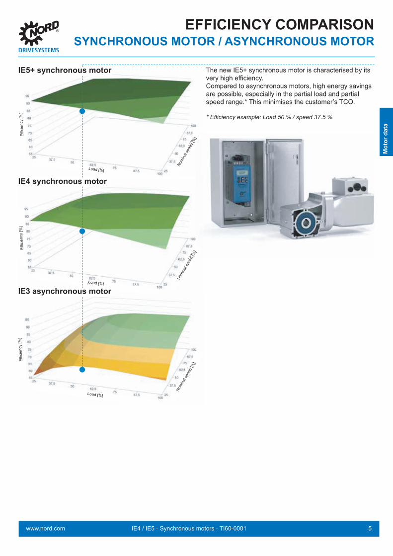
The new IE5+ synchronous motor is characterised by its very high efficiency.Compared to asynchronous motors, high energy savings are possible, especially in the partial load and partial speed range.* This minimises the customer’s TCO.
* Efficiency example: Load 50 % / speed 37.5 %
IE5+ synchronous motor
Effici
ency
[%]
Load [%]
Nom
inal s
peed
[%]
IE4 synchronous motor
Effici
ency
[%]
Load [%]
Nom
inal s
peed
[%]
IE3 asynchronous motor
Effici
ency
[%]
Load [%]
Nom
inal s
peed
[%]

6 IE4 / IE5 - Synchronous motors - TI60-0001 www.nord.com
Available motor options for IE4 PMSM 1.10 - 5.50 kW motor series
Abbreviation MeaningBRE + Brake/brake torque + suboption
RG * Rust-protected versionSR * Dust- and rust-protected versionFHL * Lockable manual releaseHL Manual releaseMIK Microswitch
NRB1 / 2 Noise-reduced brakeERD External earthing terminalTF Temperature sensor, PTC resistorTW Thermostat, bimetallicSH Anti-condensation heaterWE + 2nd shaft journal
HR Hand wheelRD Protective shieldRDT Protective shield, textile fan coverRDD Double fan coverOL Without fanOL/H Without fan, without coverKB Closed condensation drain holeMS Motor plug connectionEKK One-piece terminal boxKKV Encapsulated terminal boxFEU Humidity protection insulationTRO Tropical protection insulationF External fanRLS BackstopIG1 (IG11, 12) Incremental encoder, 1024 pulsesIG2 (IG21, 22) Incremental encoder, 2048 pulsesIG4 (IG41, 42) Incremental encoder, 4096 pulsesMG Magnetic incremental encoderIG.P Incremental encoder with plug connectorIG.K Encoder with terminal boxAG Absolute encoder
* For more information, see motor catalogue M7000
NORD IE4 OPTIONS*
Mot
or d
ata

7IE4 / IE5 - Synchronous motors - TI60-0001www.nord.com
NORD IE5OPTIONS
Available motor options for IE5+ PMSM 0.35 – 1.1 kW motor series
Abbreviation DescriptionTF Temperature sensor, PTC resistorIP69K IP69K protection classBRE Holding brakeMS MS31, MS32, MS21, MSR, MSR VAnsd tupH nsd tupH surface treatmentIG6 (IG6, IG61, IG62) Incremental encoder, 2048 pulses
IGxxP (IG62P5, IG61P8, IG62P5) Incremental encoder with 5-pin or 8-pin plug connector
Thermal motor protectionA sensible motor selection protects the motor against overheating caused by the application or the ambient conditions. Factors that could lead to overheating of the motor are, for example
■ Overload■ High ambient temperatures■ Restricted supply of cooling air■ Low motor speed due to frequency inverter operation.
NORD IE5+ motors are equipped with thermal motor protection.TF = PTC resistor temperature sensor
This is used to directly monitor the winding temperatures with full utilisation of the motor power.
Three TF temperature sensors (one for each strand) connected in series are located at the hottest points of the windings. They are connected to 2 terminals in the terminal box.
When the rated trigger temperature (NAT) is reached, the resistance of the temperature sensor suddenly increases to almost 10x its normal value.
Trigger temperature: 135° C voltage max. 30 V terminals TP1 + TP2
The PTC temperature sensor only performs its protective function when connected to a trigger device!
A triggering device evaluates the resistance increase and switches the drive off .M
otor
dat
a

8 IE4 / IE5 - Synchronous motors - TI60-0001 www.nord.com
NORD IE5OPTIONS
Encoders
Incremental encoder (IG)Modern drive applications often require speed feedback. Normally incremental encoders, which convert rotary movement into electrical signals, are used for this.
These signals are read out and processed by frequency inverters or other control devices. The incremental encoder of the IE5+ motor works according to a magnetic principle. The rotary encoder consists of two components: the magnet wheel mounted on the motor shaft, and the sensor circuit board.The integrated electronics converts the measuring signals into a digitalised square wave signal according to TTL or HTL logic.
The following confi gurations can be implemented in combination with NORD frequency inverters:■ Speed control with large adjustment range■ Highly accurate speeds, independent of the load■ Synchronisation control■ Position control■ Standstill torques■ High overload reserves
Technical dataType / Number of pulses
IG6 IG61 IG62
Interface RS 485 TTL HTL
Operating voltage +UB [V] 10 ... 30 10 ... 30 10 ... 30
Max. operating speed [rpm] 4000
Ambient temperature [°C] -25 ... +90
Protection class Corresponds to the motor protection class
Max current consumption [mA] 400 400 400

9IE4 / IE5 - Synchronous motors - TI60-0001www.nord.com
NORD IE5OPTIONS
PIN Signal Encoder connection confi guration1 +V
2012 DatumDate
NameName
WN 0-535-27(0)GezeichnetDrawn 22.11.2012 Wittlinger 0 16307 22.11.12 Wittlinger
GeprüftChecked Herr Mayer, Ind.-Nr
Ind.-No.Änderungs-Nr.Modific..-No.
DatumDate
NameName
Stift / pin Farbe / Color Signal1 Weiß / white 0V2 Braun / brown +Ub3 Grün / green A4 Gelb / yellow A \5 Grau / grey B6 Rosa / pink B \7 Blau / blue 08 Rot / red 0 \
2 B
3 0 V
4 A
5 0
PIN Signal Encoder connection confi guration1 0 V
2012 DatumDate
NameName
WN 0-535-27(0)GezeichnetDrawn 22.11.2012 Wittlinger 0 16307 22.11.12 Wittlinger
GeprüftChecked Herr Mayer, Ind.-Nr
Ind.-No.Änderungs-Nr.Modific..-No.
DatumDate
NameName
Stift / pin Farbe / Color Signal1 Weiß / white 0V2 Braun / brown +Ub3 Grün / green A4 Gelb / yellow A \5 Grau / grey B6 Rosa / pink B \7 Blau / blue 08 Rot / red 0 \
2 + UB
3 A
4 A\
5 B
6 B\
7 0
8 0\
Selection of the encoder according to the output logic is determined by the interface of the evaluation electronics. The following conditions apply to NORD frequency inverters:
NORD frequency inverter series Incremental encoder logicSK500P, SK510P HTL mit 10 – 30V VersorgungSK530P, SK550P TTL mit 10 – 30V VersorgungSK520E, SK530E, SK535E, SK540E, SK545E TTL mit 10 – 30V VersorgungSK200E, SK205E, SK210E, SK215E, SK220E, SK225E, SK230E, SK235E HTL with 10 – 30V supply
NORDAC LINK HTL with 10 – 30V supply
For further details, please refer to the operating instructions for the frequency inverter, e.g. BU 0500E.An external electronic module to convert HTL into TTL signals (e.g. connection of the encoder to 530P with very long cables) is available from NORD.
Incremental encoder mountingThe incremental encoder is fully integrated into the motor housing and is available for all variants of the IE5+ motor. This type of motor integration fully protects the encoder system against environmental infl uences. Electrical connection is established via a fl anged connector in the terminal box of the motor. Depending on the encoder variant, 5-pin or 8-pin connectors are available. The appropriate signal cable can also be supplied upon request.
Incremental encoder with 5-pin plug connector (IGxxP5)
Incremental encoder with 8-pin plug connector (IGxxP8)

10 IE4 / IE5 - Synchronous motors - TI60-0001 www.nord.com
Normal versionTerminal box for 1, plug connector for II (to fan cowl), plug connector possible for I + III
Motor plug connection (MS)
NORD IE5OPTIONS
with EMC protection
VA version
If desired, the IE5+ motors can also be supplied with motor plug connectors.The following standard motor plug connectors are available:
■ Motor plug connector MS21 (HAN Q8)■ Motor plug connector MS31 / MS32 (HAN 10E)■ Motor plug connector MSR / MSR VA
Motor plug connector MS21- Technical data:
Plug connectors: HAN Q8Number of pins: 10Current: 16 A max.Voltage: 500 V max. (600 V max. according to UL/CSA)Cage-clamp termination
Motor plug connectorMS31 / 32 / 31E / 32E- Technical data: Plug connectors: HAN 10 ES/ HAN ESS Number of pins: 10 Current: 16 A max. Voltage: 500 V max. (600 V max. according to UL/CSA) Cage-clamp termination
The MS31E and MS32E motor plug connectors are suited for applications where increased electromagnetic compatibility (EMC protection) is required.
Motor plug connector MSR / MSR VA- Technical data:
Plug connectors: M20 x 1.5 female motor thread with M23 x 1.0 connection thread
Number of pins: 8-pin (4 + 3+ PE) Current: 28 A max. Voltage: 600 V max.
Optionally available in stainless steel.The motor plug connectors are supplied without the matching connector and have a protective cap to protect against dirt.
Matching connectors are available upon request.
n 46 g1
p 11
IIIIII
II
IIII

11IE4 / IE5 - Synchronous motors - TI60-0001www.nord.com
NOTES

12 IE4 / IE5 - Synchronous motors - TI60-0001 www.nord.com
NORD IE4 / IE5BRAKE MOTORS
The selection of a standard motor-brake combination according to the overview above must be verified by careful planning! It is essential that the braking torque is specified according to the requirements of the application.
Among other things, the drive design is oriented to both the torque requirement of the application and the motor torque. If necessary, the braking torque must be reduced considerably so that the gear unit is not overloaded when large moving masses are braked.
Holding brake ● Working brake ● Emergency stop brakeThe differentiation between “holding brake”, “working brake” and “emergency stop brake” results from the type of application. A holding brake is used to prevent the movement of a drive chain which is at a standstill or nearly at a standstill. As soon as a brake needs to produce significant frictional effort it is referred to as a working brake. When selecting the brake, the relevant frictional effort as well as the actuation frequency must be determined and taken into account.
For the emergency stop brake function very large masses must be stopped once and the brake is subjected to correspondingly large energies. In this case the brake must be selected according to the maximum permissible frictional effort of each braking action.
Brakes - standard assignment for IE4/IE5 motors
MotorMN
[Nm]PN
[kW]nN
[rpm]
BRE 5 BRE 10 BRE 20 BRE 40 BRE 60MB
[Nm]fB MB
[Nm]fB MB
[Nm]fB MB
[Nm]fB MB
[Nm]fB
71N1/8 1) 1.60 0.35 2100 2.5 1.571N2/8 1) 3.20 0.70 2100 5.0 1.571N3/8 1) 4.80 1.10 2100 5.0 1.0
80T1/4 5.00 1.10 2100 5.0 1.0 10 2.0 20 * 4.080T1/4 Δ 4.80 1.50 3000 5.0 1.0 10 2.1 20 * 4.290T1/4 6.80 1.50 2100 10 1.5 20 2.9 40 * 5.990T1/4 Δ 7.00 2.20 3000 10 1.4 20 2.9 40 * 5.790T3/4 10.0 2.20 2100 10 1.0 20 2.0 40 * 4.090T3/4 Δ 9.60 3.00 3000 10 1.0 20 2.1 40 * 4.2
100T2/4 13.6 3.00 2100 20 1.5 40 2.9 60 *1) 4.4100T2/4 Δ 12.7 4.00 3000 20 1.6 40 3.1 60 *1) 4.7100T5/4 18.2 4.00 2100 20 1.1 40 2.2 60 *1) 3.3100T5/4 Δ 17.5 5.50 3000 20 1.1 40 2.3 60 *1) 3.4
Weight [kg] 2.0 3.0 5.5 7.0 10J [10-3 kgm2 ] 0.015 0.045 0.153 0.45 0.86
Braking torques printed in bold type: Standard version* IP 66 brake not possible1) Manual release not possible
IE5
IE4
Holding brake
Working brake
Emergency stop brake
Determining the brake torque

13IE4 / IE5 - Synchronous motors - TI60-0001www.nord.com
NORD IE4 / IE5
BRAKE MOTORS Application-related examples for holding brake and working brakeA frequency inverter controls the acceleration and deceleration of the application. The mechanical spring-loaded brake is only applied after the application has come to a standstill.
The brake is therefore only used for “holding” the application (parking position). It does not perform any friction work and thus no conditioning of friction surfaces.
Friction work is only transmitted in case of emergency stops or power cuts.
The geared motor is directly supplied by the local voltage supply. To slow down the application, the mechanical spring-loaded brake must generate a braking torque and thus performs friction work.
The continuous friction work ensures a conditioning of the friction pairings. The resulting friction heat must be efficiently dissipated.
The mechanical brake is also used for “holding” the application (parking position).
Holding brake
Working brake
14 IE4 / IE5 - Synchronous motors - TI60-0001 www.nord.com
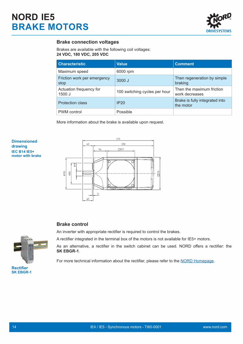
Brake connection voltagesBrakes are available with the following coil voltages:24 VDC, 180 VDC, 205 VDC
Characteristic Value Comment
Maximum speed 6000 rpmFriction work per emergency stop 3000 J Then regeneration by simple
brakingActuation frequency for 1500 J 100 switching cycles per hour Then the maximum friction
work decreases
Protection class IP20 Brake is fully integrated into the motor
PWM control Possible
More information about the brake is available upon request.
Dimensioned drawingIEC B14 IE5+ motor with brake
Brake controlAn inverter with appropriate rectifier is required to control the brakes.
A rectifier integrated in the terminal box of the motors is not available for IE5+ motors.
As an alternative, a rectifier in the switch cabinet can be used. NORD offers a rectifier: the SK EBGR-1.
For more technical information about the rectifier, please refer to the NORD Homepage.
Rectifier SK EBGR-1
NORD IE5BRAKE MOTORS

15IE4 / IE5 - Synchronous motors - TI60-0001www.nord.com
NORD IE4 / IE5PLANNING INFORMATION
GeneralRegarding the basic functionality, motors with efficiency class IE4 or IE5+ are synchronous motors, and are designed for operation with a frequency inverter. Due to their high efficiency, they offer energy saving advantages. From the efficiency point of view, the complete system must be considered.
■ Frequency inverters have an efficiency of > 95%. By optimised processes, the use of inverters can offer energy related advantages to the extent that they oppose the power loss of the individual device by a multiple (e.g. speed control for pumps instead of using throttle valves).
■ When selecting the gear units, the underlying operating factor (fB) as well as the usefulness of the motor-gear unit combination is important, especially when combining with high-efficiency synchronous motors.
■ When designing and selecting drives, the requirements for overload operation must be taken into account, in particular for unventilated motors (TENV). NORD provides planning assistance for critical applications.
NORD synchronous motorsCurrently, NORD offers motors with efficiency classes IE4 and IE5+ within the 0.35 kW – 5.5 kW power range (71 – 100 size). The motors are self-ventilated or unventilated, and are basically available with all known motor options and gear unit combinations. NORD synchronous motors are equipped with permanent magnets in the rotor package. These are inserted into recesses (the so-called IPMSM: integrated permanent magnet synchronous motor) and therefore require less use of magnet materials compared to the SPMSM (surface permanent magnet synchronous motor).A synchronous motor cannot be started and operated with mains voltage, but only with the frequency inverter. All NORD frequency inverters can operate NORD synchronous motors.In principle, NORD synchronous motors can be operated with inverters from other manufacturers. Some competitor devices have been successfully tested with our motors. The customer is responsible for the successful commissioning. Furthermore, the motor performance or the achievement of efficiencies that comply with the IE4 classification depends on the inverter and its functionality and settings.Synchronous motors from other manufacturers can be theoretically operated with the NORD inverter. This option must be checked beforehand and a test motor may be calibrated in the main production plant (consultation urgently required). NORD has already commissioned third-party motors with NORD inverters.
Planning and commissioning guide for NORD synchronous motors (PMSM) with NORD frequency inverters

16 IE4 / IE5 - Synchronous motors - TI60-0001 www.nord.com
NORD IE4 / IE5PLANNING INFORMATIONNORD PMSMs are not servo motors As synchronous motors, they do not have a load-dependent slip. The NORD motors are suitable for different nominal speeds: 1. 2,100 rpm with 140 Hz, 400 V Star (applies to the PMSM series with efficiency class IE5+) 2. 2,100 rpm with 70 Hz, 400 V Star and 230 V Delta 3. 3,000 rpm with 100 Hz and 400 V Delta
The motor is delta-connected and is theoretically operated with 70 Hz x 1.71 = 121 Hz (cf. 87 Hz characteristic curve with 50 Hz motors). As the 121 Hz operation produces loud noises (fan) and hampers the gear unit assignment, the 100 Hz, 400 V Delta type point is designated. This is not available for all NORD synchronous motors.
In addition to the selected operating points, the motor rating plate contains details on motor stator resistance RS, stator inductances Ld and Lq, and the induction voltage value (UEMK). These details are required for the inverter programming.
IE5 synchronous motor type code using the example of a 71N1/8
IE4 synchronous motor type code using the example of an 80T1/4 (Note: IE5 nomenclature)
Number of poles /8 = 8-pole
Torque class 1 … x: Coding depends on the torque within the size
Motor version N = Non-ventilated / F = Fan-cooled
Motor size (frame size) 71, 90, …
71 N 1 /8
Number of poles /4 = 4-pole
Package length 1 … 9: Coding depends on length and frame size
Winding type T = 2,100 / 3,000 rpm
Motor size (frame size) 80, 90, 100
80 T 1 /4

17IE4 / IE5 - Synchronous motors - TI60-0001www.nord.com
NORD IE4/IE5PLANNING INFORMATION
Motor-inverter assignmentThe following assignments of the motors to the respective frequency inverters apply to nominal operation. Overloads require planning and, if necessary, an adjustment of the inverter assignment.
Size MN
[Nm]
PN
[kW]
nN
[rpm]
I
[A]
η J
[kgm2]
м
[kg]
Mmax
[Nm]
KT
[Nm/А]
KE
[mV/rpm]
FI assignment
71 N1/8 1.6 0.35 2100 0.76 89.1 0.00019 4.9 4.8 2.1 143 -370-340-550-340
71 N2/8 3.2 0.7 2100 1.45 92.5 0.00038 6.0 9.6 2.2 144 -750-34071 N3/8 4.8 1.1 2100 2.14 93.6 0.00057 7.0 14.4 2.2 144 -111-340-
80T1/4 5.0 1.1 2100 2.07 90.5 0.0011 8.0 14.4 2.5 154-111-123--111-323--111-340-
80T1/4 HM 3.41 0.75 2100 1.46 90.5 0.0011 7.8 14.4 2.3 154-111-123--111-323--111-340-
80T1/4 Δ 4.8 1.5 3000 3.44 90.4 0.0011 8.0 14.4 1.4 89 -151-340-
90T1/4 6.8 1.5 2100 2.82 89.9 0.0019 10.0 21.0 2.4 156 -151-323--151-340-
90T1/4 Δ 7.0 2.2 3000 5.09 89.6 0.0019 10.0 21.0 1.4 90 -221-340-
90T3/4 10 2.2 2100 4.13 90.5 0.0024 12.0 29.0 2.4 158 -221-323--221-340-
90T3/4 HM 5.0 1.1 2100 2.08 92.7 0.0024 11.6 28.3 2.4 156 -151-323--151-340-
90T3/4 Δ 9.5 3.0 3000 6.84 92.3 0.0024 12.0 29.0 1.4 91 -301-340-
100T2/4 13.6 3.0 2100 5.4 91.4 0.00416 18.0 42.0 2.6 161 -301-323--301-340-
100T2/4 Δ 12.7 4.0 3000 8.9 92.1 0.0046 18.0 42.0 1.5 93 -401-340-
100T5/4 18.2 4.0 2100 7.1 92.1 0.0060 21.0 57.0 2.6 165 -401-323--401-340-
100T5/4 HM 10.0 2.2 2100 4.16 91.0 0.0060 20.2 53.5 2.4 165 -301-323--301-340-
100T5/4 Δ 17.5 5.5 3000 11.9 92.2 0.0060 21.0 57.0 1.5 95 -551-340-
Overloads or dynamic start/stop applications may require an inverter assignment with a higher power. For a 1:1 assignment of the motor to the inverter, up to 2x the nominal torque is possible. In theory, the motor itself can provide up to 3x the nominal torque (when starting and within the limited speed range).Continuous overload with factor of 1.4 is possible above 10 Hz (this does not apply to unventilated PMSMs).
Motor power vs. inverter powerThe inverter motor assignment is primarily made according to the power. Due to the characteristic curves, in some cases a NORD inverter with a higher power must be assigned to the motor:The inverter assignment is made for remote inverters (e.g. NORDAC PRO in the control cabinet or NORDAC LINK).
Information
Size MN PN nN I η J m Mmax kT kE Zuordnung FU[Nm] [kW] [rpm] [A] [kgm2] [kg] [Nm] [Nm/A] [mV/rpm]
71 N1/8 1,60 0,35 2100 0,76 89,1 0,00019 4.90 4,80 2,10 143 -370-340-550-340
71 N2/8 3,20 0,70 2100 1,45 92,5 0,00038 6,00 9,60 2,20 144 -750-34071 N3/8 4,80 1,10 2100 2,14 93,6 0,00057 7,00 14,4 2,20 144 -111-340-80T1/4 5,00 1,10 2100 2.07 90,5 0,0011 8,00 14,4 2,50 154 -111-123-
-111-323--111-340-
80T1/4 HM 3,41 0,75 2100 1.46 90,5 0,0011 7,80 14,4 2,30 154 -111-123--111-323--111-340-
80T1/4 ∆ 4,80 1,50 3000 3,44 90,4 0,0011 8,00 14,4 1,40 89 -151-340-90T1/4 6,80 1,50 2100 2,82 89.9 0,0019 10,0 21,0 2,40 156 -151-323-
-151-340-90T1/4 ∆ 7,00 2,20 3000 5,09 89,6 0,0019 10,0 21,0 1,40 90 -221-340-90T3/4 10,0 2,20 2100 4,13 90,5 0,0024 12,0 29,0 2,40 158 -221-323-
-221-340-90T3/4 HM 5,00 1,10 2100 2,08 92,7 0,0024 11,6 28,3 2,40 156 -151-323-
-151-340-90T3/4 ∆ 9,50 3,00 3000 6,84 92,3 0,0024 12,0 29,0 1,40 91 -301-340-100T2/4 13,6 3,00 2100 5.40 91,4 0,0046 18,0 42,0 2,60 161 -301-323-
-301-340-100T2/4 ∆ 12,7 4,00 3000 8,90 92,1 0,0046 18,0 42,0 1,50 93 -401-340-100T5/4 18,2 4,00 2100 7,10 92,1 0,0060 21,0 57,0 2,60 165 -401-323-
-401-340-100T5/4 HM 10,0 2,20 2100 4,16 91,0 0,0060 20,2 53,5 2,40 165 -301-323-
-301-340-100T5/4 ∆ 17,5 5,50 3000 11,9 92,2 0,0060 21,0 57,0 1,50 95 -551-340-
Information

18 IE4 / IE5 - Synchronous motors - TI60-0001 www.nord.com
NORD IE4 / IE5PLANNING INFORMATIONOperating modesCompared to asynchronous motors, synchronous motor operation shows the following relevant differences:
■ No mains operation NORD synchronous motors can only be operated with an inverter.
■ Field weakening rangeNORD synchronous motors cannot be operated within the field weakening range, or only to a very limited extent. During rotation, the permanent magnets in the rotor induce voltage in the stator that counteracts the terminal voltage. The induced voltage is in proportion to the motor speed, and reduces the current-driving terminal voltage. This decreases the available motor torque. Furthermore, there is a danger that due to high motor speeds high voltages may damage the inverter, e.g. in case of falling loads of lifting equipment.
■ Inverter functions Certain inverter functions are not available, e.g. DC braking.
Inverter operation supports the following control types:■ VFC open-loop mode
- Applications with linear or quadratic load characteristic curve
- Low dynamics - Very limited maximum torques
■ CFC open-loop mode - Applications with constant, linear or quadratic load torques - Moderate dynamics - Limited maximum torques
■ CFC closed-loop mode - All types of application, including lifting equipment - High dynamics - Speed-independent maximum torque
The operating mode has an impact on the drive performance:
■ Dynamics or acceleration times■ Available maximum torque depending on the speed
19IE4 / IE5 - Synchronous motors - TI60-0001www.nord.com
Commissioning1. Check the inverter selection with regard to motor assignment.2. Check the inverter selection with regard to operating mode/encoders.3. Check the motor circuit with regard to the characteristic curve and (inverter) mains voltage.4. Inverter and motor connection as known.5. Observe the safety information according to the operating instructions and work instructions.6. Connect the mains supply.7. Inverter parameterisation can be carried out with: – SimpleBox, – ParameterBox (Firmware version V4.6R1 or higher, or in ControlBox mode) – NORDCON (version 2.5 or higher, or ControlBox mode) – NORDAC ACCESS BT
8. In P200 the relevant NORD synchronous motor can be selected from the list. This ensures that the motor data are set correctly. A stator resistance measurement P220 = 1 is recommended.
9. Select the control method (P300):
VFC open-loop mode (pumps, fans), P300 = 0 Low dynamics
– From starting up to the frequency specified by P247 (switchover frequency vfc PMSM), a current is applied that decreases linearly as the frequency increases in order to force the rotor to follow (the usual setting is 25% of the nominal frequency).The current magnitude can be influenced via P210 (static boost) (low starting torques = P210 < 100 %).
– No control parameters need to be set, but the precise motor data is required, in particular RS, L and UEMK.– For stable operation, a suitable oscillation damping is necessary (P245) that quickly increases or decreases the
frequency for dynamic load changes.– When starting, the motor may briefly rotate in the opposite direction.
CFC open-loop mode, P300 = 2 Moderate dynamics
– From 0 – 10% of the synchronous speed, operation is in VFC open-loop mode. In the hysteresis range, the current falls to the value of P209 (usually 0), after which the speed is determined from the current and the operating behaviour is improved by means of speed control.
– Control parameters can be set, but the precise motor data is required, in particular RS, L and UEMK.
CFC closed-loop mode, P300 = 1 High dynamics – Slip error monitoring required P337 + P338 – Setting of the current and speed controller required
NORD IE4 / IE5PLANNING INFORMATION

20 IE4 / IE5 - Synchronous motors - TI60-0001 www.nord.com
Possible encoder systems Incremental encoder with zero track (NORDAC FLEX, NORDAC LINK)
■ Connection of the zero track to digital input 1.■ Setting P420[ 01] = 42/43 (see relevant manual).■ A method of determining the initial rotor position is required in order to determine operation until the first zero point
is passed (see below). The zero pulse corrects the error tolerances of the zero point determination method.■ If the incremental encoder is not aligned or has been misaligned due to an impact or removal of the motor, the zero
track of the incremental encoder must be aligned to the rotor position. For this, an offset is set in P334. This does not apply to IE5 PMSMs. Here, the zero track is factory-set in the encoder.
■ The activation of the slip error monitoring is mandatory (P327/P328).■ Due to the incremental measuring method, it is advisable to reference the drive at frequent intervals. If P420[ 01]
= 43 is used, this can be done by resetting the voltage. With P420[ 01] = 42, it is sufficient to clear the enabling. After a slip error message, this is done automatically.
Incremental encoder without zero track■ A method of determining the initial rotor position is required, (see below); electrically, the measurement precision is
only approx.+/- 3 – 10°; this results in a somewhat limited performance (unfavourable current-torque ratio).■ The activation of the slip error monitoring is mandatory (P327/P328). ■ Due to the incremental measuring method, it is advisable to reference the drive at frequent intervals. This can be
done by resetting the voltage. After a slip error message, this is done automatically.
Absolute/incremental combination encoders■ Absolute/incremental encoders do not require determination of the initial position (due to the absolute signal). The
encoder is adjusted by NORD prior to delivery of the geared motor and does not require an offset determination.■ The activation of the slip error monitoring is mandatory (P327/P328).
Determination of the initial rotor positionWith incremental encoders, determination of the initial rotor position is required each time that the mains voltage is switched on or after certain inverter errors.
a. By the test signal method (P330 = 1)Determination of the rotor position by test measurement (duration approx. 1 second). With P212, the current used for measurement can be amplified in order to achieve a better result under unfavourable conditions.
b. By the dwell method (P330 = 0, voltage-controlled) The voltage forces the rotor into the zero position and therefore aligns the motor. This method is only possible for horizontal applications, e.g. for torque-free drive units without motor brake (Caution: The shaft turns during the movement).
The information in the relevant manuals must be observed.Reference to document AG 0101 is recommended for setting and optimising the controller.
NORD IE4 / IE5PLANNING INFORMATION

21IE4 / IE5 - Synchronous motors - TI60-0001www.nord.com
NORD IE5+ Synchronous motors- are not ventilated by default- Cooling type IC410 according to EN 60034-6
Overview of cooling types:
Designation English short form (NEMA)IC410 Without fan TENVIC411 Self-ventilated TEFCIC416 Externally ventilated TEBC
Vibration level A according to DIN EN 60034-14NORD synchronous motors are designed according to vibration level A.
Cable glands
Type Dimensions
71 1 x M25 x 1.52 x M16 x 1.5
NORD IE4 / IE5PLANNING INFORMATION IE5
22 IE4 / IE5 - Synchronous motors - TI60-0001 www.nord.com
NORD IE4 / IE5PLANNING INFORMATION
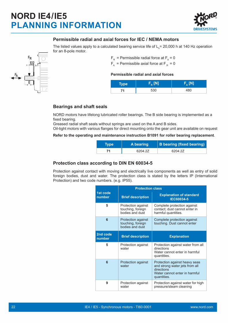
Permissible radial and axial forces for IEC / NEMA motorsThe listed values apply to a calculated bearing service life of Lh= 20,000 h at 140 Hz operation for an 8-pole motor.
FR = Permissible radial force at FA = 0 FA = Permissible axial force at F R = 0
Permissible radial and axial forces
Type FR [N] FA [N]
71 530 480
Bearings and shaft sealsNORD motors have lifelong lubricated roller bearings. The B side bearing is implemented as a fixed bearing.Greased radial shaft seals without springs are used on the A and B sides.Oil-tight motors with various flanges for direct mounting onto the gear unit are available on request
Refer to the operating and maintenance instruction B1091 for roller bearing replacement.
Type A bearing B bearing (fixed bearing)71 6204.2Z 6204.2Z
Protection class according to DIN EN 60034-5Protection against contact with moving and electrically live components as well as entry of solid foreign bodies, dust and water. The protection class is stated by the letters IP (International Protection) and two code numbers. (e.g. IP55).
1st code number
Protection class
Brief description Explanation of standard IEC60034-5
5 Protection against touching, foreign bodies and dust
Complete protection against contact; dust cannot enter in harmful quantities.
6 Protection against touching, foreign bodies and dust
Complete protection against touching. Dust cannot enter
2nd code number Brief description Explanation
5 Protection against water
Protection against water from all directions Water cannot enter in harmful quantities.
6 Protection against water
Protection against heavy seas and strong water jets from all directions Water cannot enter in harmful quantities.
9 Protection against water
Protection against water for high pressure/steam cleaning
E/2E/2
EE
FFRR
AAFF

23IE4 / IE5 - Synchronous motors - TI60-0001www.nord.com
NOTES

24 IE4 / IE5 - Synchronous motors - TI60-0001 www.nord.com
NORD IE5MOTOR DATA
71 N1/8
71 N2/8
71 N1/8 71 N2/8
Cur
rent
(A)
Speed (rpm)
Torq
ue (N
m)
Nominal torque
Overload torque, short-term (with sensor)
Nominal current
Overload current, short-term (with sensor)
Cur
rent
(A)
Speed (rpm)
Torq
ue (N
m)
Nominal torque
Overload torque, short-term (with sensor)
Nominal current
Overload current, short-term (with sensor)

25IE4 / IE5 - Synchronous motors - TI60-0001www.nord.com
71 N3/8
NORD IE5MOTOR DATA71 N3/8
Cur
rent
(A)
Speed (rpm)
Torq
ue (N
m)
Nominal torque
Overload torque, short-term (with sensor)
Nominal current
Overload current, short-term (with sensor)

26 IE4 / IE5 - Synchronous motors - TI60-0001 www.nord.com
NORD IE4MOTOR DATA 80 T1/4 80 T1/4D
80 T1/4 EigenbelüftetD
reh
mo
me
nt
( N
m )
Drehzahl ( 1/min )Nennmoment
Überlastdrehmoment (dauerhaft)
Überlastmoment kurzzeitig (mit Sensor)
Nennstrom
Überlaststrom (dauerhaft)
Überlaststrom kurzzeitig (mit Sensor)
Str
om
(A
)
0,0
2,5
5,0
7,5
10,0
12,5
0,0
5,0
10,0
15,0
20,0
25,0
0 500 1000 1500 2000 2500 3000 3500
80 T1/4 Self-ventilated
80 T1/4D
Cur
rent
(A)
Speed (rpm)
Torq
ue (N
m)
Nominal torque
Overload torque (continuous)
Overload torque, short-term (with sensor)
Nominal current
Overload current (continuous)
Overload current, short-term (with sensor)
Cur
rent
(A)
Speed (rpm)
Torq
ue (N
m)
Nominal torque
Overload torque (continuous)
Overload torque, short-term (with sensor)
Nominal current
Overload current (continuous)
Overload current, short-term (with sensor)

27IE4 / IE5 - Synchronous motors - TI60-0001www.nord.com
NORD IE4MOTOR DATA
90 T1/4
90 T1/4D
90 T1/4 90 T1/4D
Cur
rent
(A)
Speed (rpm)
Torq
ue (N
m)
Nominal torque
Overload torque (continuous)
Overload torque, short-term (with sensor)
Nominal current
Overload current (continuous)
Overload current, short-term (with sensor)
Cur
rent
(A)
Speed (rpm)
Torq
ue (N
m)
Nominal torque
Overload torque (continuous)
Overload torque, short-term (with sensor)
Nominal current
Overload current (continuous)
Overload current, short-term (with sensor)

28 IE4 / IE5 - Synchronous motors - TI60-0001 www.nord.com
90 T3/4
90 T3/4D
NORD IE4MOTOR DATA 90 T3/4 90 T3/4D
Cur
rent
(A)
Speed (rpm)
Torq
ue (N
m)
Nominal torque
Overload torque (continuous)
Overload torque, short-term (with sensor)
Nominal current
Overload current (continuous)
Overload current, short-term (with sensor)
Cur
rent
(A)
Speed (rpm)
Torq
ue (N
m)
Nominal torque
Overload torque (continuous)
Overload torque, short-term (with sensor)
Nominal current
Overload current (continuous)
Overload current, short-term (with sensor)

29IE4 / IE5 - Synchronous motors - TI60-0001www.nord.com
NORD IE4MOTOR DATA
100 T2/4
100 T2/4D
100 T2/4 100 T2/4D
Cur
rent
(A)
Speed (rpm)
Torq
ue (N
m)
Nominal torque
Overload torque (continuous)
Overload torque, short-term (with sensor)
Nominal current
Overload current (continuous)
Overload current, short-term (with sensor)
Cur
rent
(A)
Speed (rpm)
Torq
ue (N
m)
Nominal torque
Overload torque (continuous)
Overload torque, short-term (with sensor)
Nominal current
Overload current (continuous)
Overload current, short-term (with sensor)

30 IE4 / IE5 - Synchronous motors - TI60-0001 www.nord.com
100 T5/4
100 T5/4D
NORD IE4MOTOR DATA 100 T5/4 100 T5/4D
Cur
rent
(A)
Speed (rpm)
Torq
ue (N
m)
Nominal torque
Overload torque (continuous)
Overload torque, short-term (with sensor)
Nominal current
Overload current (continuous)
Overload current, short-term (with sensor)
Cur
rent
(A)
Speed (rpm)
Torq
ue (N
m)
Nominal torque
Overload torque (continuous)
Overload torque, short-term (with sensor)
Nominal current
Overload current (continuous)
Overload current, short-term (with sensor)

31IE4 / IE5 - Synchronous motors - TI60-0001www.nord.com
NORD IE4 HMMOTOR DATA
80 T1/4 HM
90 T3/4 HM
80 T1/4 HM 90 T3/4 HM
Cur
rent
(A)
Speed (rpm)
Torq
ue (N
m)
Nominal torque
Overload torque, short-term
Nominal current
Overload current, short-term
Cur
rent
(A)
Speed (rpm)
Torq
ue (N
m)
Nominal torque
Overload torque, short-term
Nominal current
Overload current, short-term

32 IE4 / IE5 - Synchronous motors - TI60-0001 www.nord.com
NORD IE4 HMMOTOR DATA 100 T5/4 HM
100 T5/4 HM
Cur
rent
(A)
Speed (rpm)
Torq
ue (N
m)
Nominal torque
Overload torque, short-term
Nominal current
Overload current, short-term

33IE4 / IE5 - Synchronous motors - TI60-0001www.nord.com
NOTES

34 IE4 / IE5 - Synchronous motors - TI60-0001 www.nord.com
NORD IE5B5
71Nx/8ØP ØN ØD
L
LLHHE
LET
DB
GA
FØM
4 x ØS
AD
EB
ØAC
AGLA
IM B5
IM V1 IM V3
IM B5
IM V1 IM V3
IM B5
IM V1 IM V3
Type
LA M N P S D AC AD AG HH L LE LL D DB E EB F GA71Nx/8 11 165 130 200 11 4.0 125 121 105 55 228 40 105 19 M6 40 32 6 21.5

35IE4 / IE5 - Synchronous motors - TI60-0001www.nord.com
NORD IE5B5 BRE
71Nx/8ØP ØN ØD
L
LLHHE
LET
DB
GA
FØM
4 x ØS
AD
EB
ØAC
AGLA
Type
LA M N P S D AC AD AG HH L LE LL D DB E EB F GA71Nx/8 11 165 130 200 11 4.0 125 121 105 55 274 40 105 19 M6 40 32 6 21.5
2
4
1
I
I
II
I
IIIV
III
3

36 IE4 / IE5 - Synchronous motors - TI60-0001 www.nord.com
71Nx/8
NORD IE5B14
ØP ØN
L
ØD
LLHHE
LET
GA
F
ØAC
EBDB
AD
AG
ØM
4 x ØSE2
IM B5
IM V1 IM V3
Type
M N P S D AC AD AG HH L LE LL D DB E EB F GA71Nx/8 100 80 120 M6x15 3.0 125 121 105 55 228 40 105 19 M6 40 32 6 21.5

37IE4 / IE5 - Synchronous motors - TI60-0001www.nord.com
71Nx/8
NORD IE5B14 BRE
2
4
1
III
I
I
II
I
IIIV
3
ØP ØN
LØD
LLHHE
LET
GA
F
ØAC
EBDB
AD
AG
ØM
4 x ØS
Type
M N P S D AC AD AG HH L LE LL D DB E EB F GA71Nx/8 100 80 120 M6x15 3.0 125 121 105 55 274 40 105 19 M6 40 32 6 21.5

38 IE4 / IE5 - Synchronous motors - TI60-0001 www.nord.com
NORD IE5NEMA
ØP ØN ØD
TLE
LE
HH LL
F
GA
EBE2
LA
ØAC
DB
4 x ØS
ØM
AD
AG
71Nx/8
IM B5
IM V1 IM V3
Type
LA M N P S D AC AD AG HH L LE LL D DB E E2 EB F GA71Nx/8 11 149.2 114.3 165 M6x15 4.0 125 121 105 55 236 47.6 105 15.87 M6 47.6 1.5 42.9 4.76 17.9
39IE4 / IE5 - Synchronous motors - TI60-0001www.nord.com
Type
LA M N P S D AC AD AG HH L LE LL D DB E E2 EB F GA71Nx/8 11 149.2 114.3 165 M6x15 4.0 125 121 105 55 236 47.6 105 15.87 M6 47.6 1.5 42.9 4.76 17.9
2
4
1
III
I
IIIV
II
I
3
I
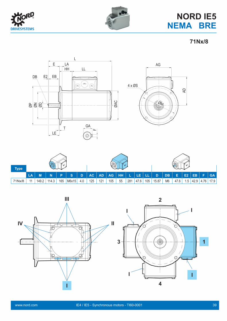
NORD IE5NEMA BRE
ØP ØN ØD
TLE
LE
HH LL
F
GA
EBE2
LA
ØAC
DB
4 x ØS
ØM
AD
AG
71Nx/8
Type
LA M N P S D AC AD AG HH L LE LL D DB E E2 EB F GA71Nx/8 11 149.2 114.3 165 M6x15 4.0 125 121 105 55 281 47.6 105 15.87 M6 47.6 1.5 42.9 4.76 17.9

40 IE4 / IE5 - Synchronous motors - TI60-0001 www.nord.com
ØD
ØN
ØP
TLE
ØS
ØM
E LA
DB
AG
AD
HH
O
LL
L
GA
F
EB
ØAC
IM B5
IM V1 IM V3
NORD IE4B5
Type
LA M N P S D AC AD AG HH L LC LE LL80 11 165 130 200 11 3.5 156 142 114 22 276 309 40 11490 11 165 130 200 11 3.5 176 147 114 26 326 373 50 114
100 15 215 180 250 13.5 4.0 194 169 114 32 366 422 60 114

41IE4 / IE5 - Synchronous motors - TI60-0001www.nord.com
NORD IE4
B5
LG O D DB E EB F GA DA DC EA EC FA GC337 M25 x 1.5 19 M6 40 32 6 21.5 14 M5 30 20 5 16.0398 M25 x 1.5 24 M8 50 40 8 27.0 19 M6 40 32 6 21.5435 M32 x 1.5 28 M10 60 50 8 31.0 24 M8 50 40 8 27.0
LG
Option IG
2
4
3 1
III
II IV
II
II
I

42 IE4 / IE5 - Synchronous motors - TI60-0001 www.nord.com
NORD IE4B14
Type
M N P S D AC AD AG HH L LC LE LL80 100 80 120 M6 x 12 3.0 156 142 114 22 276 309 40 11490 115 95 140 M8 x 15 3.0 176 147 114 26 326 373 50 114
100 130 110 160 M8 x 16 3.5 194 169 114 32 366 422 60 114
AG
AD
ØM
S
DBF
GA
LET
ØPØN
ØD
EB O
EHH LL
ØAC
L
IM B14
IM V18 IM V19

43IE4 / IE5 - Synchronous motors - TI60-0001www.nord.com
NORD IE4
B14
LG O D DB E EB F GA DA DC EA EC FA GC337 M25 x 1.5 19 M6 40 32 6 21.5 14 M5 30 20 5 16.0398 M25 x 1.5 24 M8 50 40 8 27.0 19 M6 40 32 6 21.5435 M32 x 1.5 28 M10 60 50 8 31.0 24 M8 50 40 8 27.0
LG
Option IG
2
4
3 1
III
II IV
I I
II
I

44 IE4 / IE5 - Synchronous motors - TI60-0001 www.nord.com
NOTES
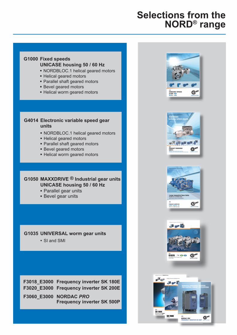
Selections from the NORD® range
G4014 Electronic variable speed gear units▪ NORDBLOC.1 helical geared motors▪ Helical geared motors▪ Parallel shaft geared motors▪ Bevel geared motors▪ Helical worm geared motors
G1050 MAXXDRIVE ® Industrial gear unitsUNICASE housing 50 / 60 Hz▪ Parallel gear units▪ Bevel gear units
G1035 UNIVERSAL worm gear units▪ SI and SMI
ELECTRONICVARIABLE SPEED DRIVES
Headquarters:Getriebebau NORD GmbH & Co. KGGetriebebau-Nord-Straße 122941 Bargteheide, GermanyFon +49 (0) 4532 / 289 - 0 Fax +49 (0) 4532 / 289 - [email protected], www.nord.comMember of the NORD DRIVESYSTEMS Group
Intelligent Drivesystems, Worldwide Services
G401
4EL
ECTR
ONIC
VARI
ABLE
SPEE
D DR
IVES
NORD DRIVESYSTEMS GROUPHeadquarters and Technology Centerin Bargteheide near Hamburg, GermanyInnovative drive solutionsfor more than 100 industriesMechanic ProductsHelical, Parallel Shaft, Helical Bevel and Helical Worm Gear UnitsElectrical ProductsElectric motors in all efficiency classesElectronic ProductsCentralized and decentralized frequency inverters, Motor starters7 state-of-the-art production plantsfor all drive components36 subsidiaries on 5 continentsprovide on-site storage, assembly centers, technical support and customer serviceMore than 3.100 employees around the worldcreate customized solutions
www.nord.com/locator
DRIVESYSTEMS
G401
4 Mat.
-Nr. 6
0040
02 /
4214
NORDBLOC.1 Helical Gear Units, Helical Gear Units, Parallel Gear Units, Helical-Bevel Gear Units, Helical-Worm Gear Units
PRODUCT OVERVIEWG4014
EN
EN
www.nord.com/locator
G103
5 W
ORM
GEAR
UNITS
Mat
.-Nr. 6
0015
02/4
813
Intelligent Drivesystems, Worldwide Services
G1035UNIVERSAL Worm gear unitsSI und SMI
EN
EN
NORD Drivesystems | Global, always close to you
Headquarters:Getriebebau NORD GmbH & Co. KGGetriebebau-Nord-Straße 122941 Bargteheide, GermanyFon +49 (0) 4532 / 289 - 0 Fax +49 (0) 4532 / 289 - [email protected], www.nord.com
Member of the NORD DRIVESYSTEMS Group
DE
Intelligent Drivesystems, Worldwide Services
SK 180EDezentrale Antriebstechnik Frequenzumrichter
50 H
z • m
m F
ESTE
DRE
HZAH
LEN
DRIVESYSTEMS
Intelligent Drivesystems, Worldwide Services
G100
0 M
at.-N
r. 60
0180
2 / 4
815
G100
0EN
50 Hz • mm
CONSTANT SPEEDS G1000
ENHeadquarters:Getriebebau NORD GmbH & Co. KGGetriebebau-Nord-Straße 122941 Bargteheide, GermanyFon +49 (0) 4532 / 289 - 0 Fax +49 (0) 4532 / 289 - [email protected], www.nord.comMember of the NORD DRIVESYSTEMS Group
NORD DRIVESYSTEMS GROUPHeadquarters and Technology Centerin Bargteheide near Hamburg, GermanyInnovative drive solutions for more than 100 industriesMechanic ProductsHelical, Parallel Shaft, Helical Bevel and Helical Worm Gear UnitsElectrical ProductsElectric motors in all effi ciency classesElectronic ProductsCentralized and decentralized frequency inverters, Motor starters7 state-of-the-art production plantsfor all drive components36 subsidiaries on 5 continentsprovide on-site storage, assembly centers, technical support and customer serviceMore than 3.200 employees around the worldcreate customized solutions
www.nord.com/locator 50 H
z • m
m C
ONST
ANT
SPEE
DS
PRODUCT OVERVIEWG1050 • 50/60 Hz • mm
G105
0 M
at.-N
r. 60
0110
2 / 1
516
SK 7207 - SK 15507 Gear Units
50/6
0 Hz
•m
m
NORD
GEA
R - L
ARGE
INDU
STRI
AL G
EAR
UNIT
SG1
050
Large Industrial Gear UnitsParallel-Axis and Right-AngleHigh Precision, Long Life, Low Maintenance
Headquarters:Getriebebau NORD GmbH & Co. KGGetriebebau-Nord-Straße 122941 Bargteheide, GermanyFon +49 (0) 4532 / 289 - 0 Fax +49 (0) 4532 / 289 - [email protected], www.nord.comMember of the NORD DRIVESYSTEMS Group
NORD DRIVESYSTEMS GROUPHeadquarters and Technology Centerin Bargteheide near Hamburg, GermanyInnovative drive solutions for more than 100 industriesMechanic ProductsHelical, Parallel Shaft, Helical Bevel and Helical Worm Gear UnitsElectrical ProductsElectric motors in all efficiency classesElectronic ProductsCentralized and decentralized frequency inverters, Motor starters7 state-of-the-art production plantsfor all drive components36 subsidiaries on 5 continentsprovide on-site storage, assembly centers, technical support and customer serviceMore than 3.200 employees around the worldcreate customized solutions
www.nord.com/locator
Intelligent Drivesystems, Worldwide Services
EN
Intelligent Drivesystems, Worldwide Services
Dezentrale Antriebstechnik Frequenzumrichter
Intelligent Drivesystems, Worldwide Services
F 3020 DE
SK 200E
G1000 Fixed speedsUNICASE housing 50 / 60 Hz▪ NORDBLOC.1 helical geared motors▪ Helical geared motors▪ Parallel shaft geared motors▪ Bevel geared motors▪ Helical worm geared motors
F3018_E3000 Frequency inverter SK 180EF3020_E3000 Frequency inverter SK 200E
F3060_E3000 NORDAC PROFrequency inverter SK 500P
NORDAC PRO FREQUENCY INVERTER SK 500P
EN
VERSATILE FREQUENCY INVERTER FOR CONTROL CABINET APPLICATIONS
Intelligent Drivesystems, Worldwide Services

Intelligent Drivesystems, Worldwide Services
TI60
-000
1 Par
t No.
6092
002 /
4820
NORD DRIVESYSTEMS ® Group
Headquarters and technology centrein Bargteheide near Hamburg
Innovative drive solutions for more than 100 branches of industry
Mechanical productsparallel shaft, helical, bevel and worm gear units
Electrical productsIE2/IE3/IE4 motors
Electronic productscentralised and decentralised frequency inverters, motor starters, and fi eld distributors
7 production locations with cutting edge technologyfor all drive components
Subsidiaries and sales partners in 98 countries on 5 continentsprovide local stocks, assembly centres, technical support and customer service
More than 4,000 employees throughout the worldcreate customised solutions.
www.nord.com/locator
Intelligent Drivesystems, Worldwide Services
NORD GEAR LTD.11 Barton LaneAbingdon Science Park, AbingdonOX14 3NB OxfordshireTel. +44-1235-534404Fax. [email protected]
EN
Member of the NORD DRIVESYSTEMS Group
Related Documents