IDSC-C1DR/C1DT-A-E ID Controller User’s Manual Revised December 2004

Welcome message from author
This document is posted to help you gain knowledge. Please leave a comment to let me know what you think about it! Share it to your friends and learn new things together.
Transcript
IDSC-C1DR/C1DT-A-EID ControllerUser’s Manual
Revised December 2004
!
!
!
v
Notice:OMRON products are manufactured for use according to proper procedures by a qualified operatorand only for the purposes described in this manual.
The following conventions are used to indicate and classify precautions in this manual. Always heedthe information provided with them. Failure to heed precautions can result in injury to people or dam-age to the product.
DANGER Indicates an imminently hazardous situation which, if not avoided, will result in death orserious injury.
WARNING Indicates a potentially hazardous situation which, if not avoided, could result in death orserious injury.
Caution Indicates a potentially hazardous situation which, if not avoided, may result in minor ormoderate injury, or property damage.
OMRON Product ReferencesAll OMRON products are capitalized in this manual. The word “Unit” is also capitalized when it refersto an OMRON product, regardless of whether or not it appears in the proper name of the product.
The abbreviation “Ch,” which appears in some displays and on some OMRON products, often means“word” and is abbreviated “Wd” in documentation in this sense.
The abbreviation “PC” means Programmable Controller and is not used as an abbreviation for any-thing else.
Visual AidsThe following headings appear in the left column of the manual to help you locate different types ofinformation.
Note Indicates information of particular interest for efficient and convenient operationof the product.
1, 2, 3... 1. Indicates lists of one sort or another, such as procedures, checklists, etc.
OMRON, 1995All rights reserved. No part of this publication may be reproduced, stored in a retrieval system, or transmitted, in anyform, or by any means, mechanical, electronic, photocopying, recording, or otherwise, without the prior written permis-sion of OMRON.
No patent liability is assumed with respect to the use of the information contained herein. Moreover, because OMRON isconstantly striving to improve its high-quality products, the information contained in this manual is subject to changewithout notice. Every precaution has been taken in the preparation of this manual. Nevertheless, OMRON assumes noresponsibility for errors or omissions. Neither is any liability assumed for damages resulting from the use of the informa-tion contained in this publication.
TABLE OF CONTENTS
vii
SECTION 1Features and System Configuration 1. . . . . . . . . . . . . . . . .
1-1 ID Controller Features 2. . . . . . . . . . . . . . . . . . . . . . . . . . . . . . . . . . . . . . . . . . . . . . . . . . . . 1-2 Overall ID Controller Procedure 7. . . . . . . . . . . . . . . . . . . . . . . . . . . . . . . . . . . . . . . . . . . .
SECTION 2Hardware Components and Installation 9. . . . . . . . . . . . .
2-1 Component Names and Functions 10. . . . . . . . . . . . . . . . . . . . . . . . . . . . . . . . . . . . . . . . . . . 2-2 System Configuration and Installation 15. . . . . . . . . . . . . . . . . . . . . . . . . . . . . . . . . . . . . . . . 2-3 Installing the ID Controller 28. . . . . . . . . . . . . . . . . . . . . . . . . . . . . . . . . . . . . . . . . . . . . . . .
SECTION 3Programming Device Operations 33. . . . . . . . . . . . . . . . . . .
3-1 Applicable Programming Devices 34. . . . . . . . . . . . . . . . . . . . . . . . . . . . . . . . . . . . . . . . . . . 3-2 Programming Console Preparations 34. . . . . . . . . . . . . . . . . . . . . . . . . . . . . . . . . . . . . . . . . . 3-3 Programming Console Operations 37. . . . . . . . . . . . . . . . . . . . . . . . . . . . . . . . . . . . . . . . . . . 3-4 LSS Operations 52. . . . . . . . . . . . . . . . . . . . . . . . . . . . . . . . . . . . . . . . . . . . . . . . . . . . . . . . . . 3-5 SSS Operations 53. . . . . . . . . . . . . . . . . . . . . . . . . . . . . . . . . . . . . . . . . . . . . . . . . . . . . . . . . .
SECTION 4Data Areas 55. . . . . . . . . . . . . . . . . . . . . . . . . . . . . . . . . . . . .
4-1 Data Area Structure 56. . . . . . . . . . . . . . . . . . . . . . . . . . . . . . . . . . . . . . . . . . . . . . . . . . . . . . 4-2 Data Area Functions 57. . . . . . . . . . . . . . . . . . . . . . . . . . . . . . . . . . . . . . . . . . . . . . . . . . . . . . 4-3 ID Controller Area 60. . . . . . . . . . . . . . . . . . . . . . . . . . . . . . . . . . . . . . . . . . . . . . . . . . . . . . .
SECTION 5ID Controller Functions and Setup 63. . . . . . . . . . . . . . . . .
5-1 ID Controller Setup 64. . . . . . . . . . . . . . . . . . . . . . . . . . . . . . . . . . . . . . . . . . . . . . . . . . . . . . 5-2 Basic Operations and I/O Processes 69. . . . . . . . . . . . . . . . . . . . . . . . . . . . . . . . . . . . . . . . . . 5-3 ID Communications 73. . . . . . . . . . . . . . . . . . . . . . . . . . . . . . . . . . . . . . . . . . . . . . . . . . . . . . 5-4 Advanced I/O Instructions 86. . . . . . . . . . . . . . . . . . . . . . . . . . . . . . . . . . . . . . . . . . . . . . . . . 5-5 Using Interrupts 94. . . . . . . . . . . . . . . . . . . . . . . . . . . . . . . . . . . . . . . . . . . . . . . . . . . . . . . . . 5-6 Communications 110. . . . . . . . . . . . . . . . . . . . . . . . . . . . . . . . . . . . . . . . . . . . . . . . . . . . . . . . .
SECTION 6Programming 121. . . . . . . . . . . . . . . . . . . . . . . . . . . . . . . . . . .
6-1 Instruction Set 122. . . . . . . . . . . . . . . . . . . . . . . . . . . . . . . . . . . . . . . . . . . . . . . . . . . . . . . . . . 6-2 Basic Programming Concepts 126. . . . . . . . . . . . . . . . . . . . . . . . . . . . . . . . . . . . . . . . . . . . . . 6-3 ID Communications Instructions 134. . . . . . . . . . . . . . . . . . . . . . . . . . . . . . . . . . . . . . . . . . . . 6-4 Basic Instructions 140. . . . . . . . . . . . . . . . . . . . . . . . . . . . . . . . . . . . . . . . . . . . . . . . . . . . . . . . 6-5 Selected Special Instructions 145. . . . . . . . . . . . . . . . . . . . . . . . . . . . . . . . . . . . . . . . . . . . . . .
SECTION 7Programming Examples 155. . . . . . . . . . . . . . . . . . . . . . . . . .
7-1 Recording Data 156. . . . . . . . . . . . . . . . . . . . . . . . . . . . . . . . . . . . . . . . . . . . . . . . . . . . . . . . . . 7-2 Displaying Worker Instructions 157. . . . . . . . . . . . . . . . . . . . . . . . . . . . . . . . . . . . . . . . . . . . . 7-3 Managing Production Histories 158. . . . . . . . . . . . . . . . . . . . . . . . . . . . . . . . . . . . . . . . . . . . . 7-4 Controlling Workpiece Flow 159. . . . . . . . . . . . . . . . . . . . . . . . . . . . . . . . . . . . . . . . . . . . . . .
SECTION 8Internal Processing 161. . . . . . . . . . . . . . . . . . . . . . . . . . . . . .
8-1 Internal Processing 162. . . . . . . . . . . . . . . . . . . . . . . . . . . . . . . . . . . . . . . . . . . . . . . . . . . . . . . 8-2 Computing the Cycle Time 163. . . . . . . . . . . . . . . . . . . . . . . . . . . . . . . . . . . . . . . . . . . . . . . . 8-3 Execution Times for ID Communications 165. . . . . . . . . . . . . . . . . . . . . . . . . . . . . . . . . . . . .
TABLE OF CONTENTS
viii
SECTION 9Troubleshooting 171. . . . . . . . . . . . . . . . . . . . . . . . . . . . . . . . .
9-1 Introduction 172. . . . . . . . . . . . . . . . . . . . . . . . . . . . . . . . . . . . . . . . . . . . . . . . . . . . . . . . . . . . 9-2 Programming Console Operation Errors 173. . . . . . . . . . . . . . . . . . . . . . . . . . . . . . . . . . . . . . 9-3 Programming Errors 173. . . . . . . . . . . . . . . . . . . . . . . . . . . . . . . . . . . . . . . . . . . . . . . . . . . . . . 9-4 User-defined Errors 174. . . . . . . . . . . . . . . . . . . . . . . . . . . . . . . . . . . . . . . . . . . . . . . . . . . . . . 9-5 Operating Errors 175. . . . . . . . . . . . . . . . . . . . . . . . . . . . . . . . . . . . . . . . . . . . . . . . . . . . . . . . . 9-6 ID Indicators 177. . . . . . . . . . . . . . . . . . . . . . . . . . . . . . . . . . . . . . . . . . . . . . . . . . . . . . . . . . . . 9-7 ID Controller Flags 178. . . . . . . . . . . . . . . . . . . . . . . . . . . . . . . . . . . . . . . . . . . . . . . . . . . . . . . 9-8 ID Error Logs 179. . . . . . . . . . . . . . . . . . . . . . . . . . . . . . . . . . . . . . . . . . . . . . . . . . . . . . . . . . . 9-9 Troubleshooting Flowcharts 181. . . . . . . . . . . . . . . . . . . . . . . . . . . . . . . . . . . . . . . . . . . . . . . .
AppendicesA Standard Models 189. . . . . . . . . . . . . . . . . . . . . . . . . . . . . . . . . . . . . . . . . . . . . . . . . . . . . . . . . . . B Specifications 191. . . . . . . . . . . . . . . . . . . . . . . . . . . . . . . . . . . . . . . . . . . . . . . . . . . . . . . . . . . . . . C Dimensions 193. . . . . . . . . . . . . . . . . . . . . . . . . . . . . . . . . . . . . . . . . . . . . . . . . . . . . . . . . . . . . . . . D SR and AR Area Allocations 195. . . . . . . . . . . . . . . . . . . . . . . . . . . . . . . . . . . . . . . . . . . . . . . . . . E Extended ASCII 201. . . . . . . . . . . . . . . . . . . . . . . . . . . . . . . . . . . . . . . . . . . . . . . . . . . . . . . . . . . .
Glossary 203. . . . . . . . . . . . . . . . . . . . . . . . . . . . . . . . . . . . . . . Index 217. . . . . . . . . . . . . . . . . . . . . . . . . . . . . . . . . . . . . . . . . .
Revision History 223. . . . . . . . . . . . . . . . . . . . . . . . . . . . . . . . .

ix
About this Manual:
This manual describes the installation and operation of the IDSC-C1DR-AE and IDSC-C1DT-AE ID Con-trollers and includes the sections described below. These ID Controllers provide complete ProgrammableController (PC) functionality and use a electromagnetic coupling system to enable construction of non-contact information recognition (IDentification) systems.
Although this is the only manual provided specially for the ID Controllers, the following manuals must bereferenced as required when setting up, programming, installing, and operating an ID Controller System.
Information on ManualConstructing ID Systems, including informa-tion on Read/Write Heads, Data Carriers, etc.
V600 FA ID Sensor Serial Interface Operation Manual (Z44)
V600 FA ID Sensor Parallel Interface Operation Manual (Z45)
Programmable Controllers CQM1 Programmable Controller Programming Manual (W228)
Inputting programs or operating PCs SYSMAC C-Series PC Ladder Support SoftwareOperation Manual (W237)
Please read this manual and the related manuals carefully and be sure you understand the informationprovided before attempting to install and operate an ID Controller.
Section 1 describes the features of an ID Controller and the types of system configuration in which it canbe used.
Section 2 describes the components that make up an ID Controller and the procedures necessary toinstall and mount an ID Controller.
Section 3 describes the Programming Console, Ladder Support Software (LSS) Operations, and SYS-MAC Support Software (SSS) Operations used with an ID Controller System.
Section 4 describes the structure and use of the data areas used by the ID Controller.
Section 5 describes the functions of the ID Controller and the Setup that can be used to control thosefunctions.
Section 6 describes some of the ladder-diagram programming used to program the ID Controller. Referto the CQM1 Programming Manual for more information on ladder-diagram programming.
Section 7 provides four programming examples using ID communications instructions.
Section 8 described the processing that takes place within the ID Controller and explains how to calculatethe time required for program execution and related processing (called the scan time).
Section 9 describes how to diagnose and correct the hardware and software errors that can occur duringID Controller operation and how to create user errors based on program execution.
The Appendices provide information on standard models, specifications, dimensions, SR and AR Areaallocations, and extended ASCII.
WARNING Failure to read and understand the information provided in this manual may result inpersonal injury or death, damage to the product, or product failure. Please read eachsection in its entirety and be sure you understand the information provided in the sectionand related sections before attempting any of the procedures or operations given.
!
1
SECTION 1Features and System Configuration
This section describes the features of an ID Controller and the types of system configuration in which it can be used.
1-1 ID Controller Features 2. . . . . . . . . . . . . . . . . . . . . . . . . . . . . . . . . . . . . . . . . . . . . . . . . . . . . 1-1-1 Overview 2. . . . . . . . . . . . . . . . . . . . . . . . . . . . . . . . . . . . . . . . . . . . . . . . . . . . . . . . 1-1-2 ID Controller Features 3. . . . . . . . . . . . . . . . . . . . . . . . . . . . . . . . . . . . . . . . . . . . . . 1-1-3 ID Controller Functions 3. . . . . . . . . . . . . . . . . . . . . . . . . . . . . . . . . . . . . . . . . . . . . 1-1-4 ID Controller Applications 4. . . . . . . . . . . . . . . . . . . . . . . . . . . . . . . . . . . . . . . . . .
1-2 Overall ID Controller Procedure 7. . . . . . . . . . . . . . . . . . . . . . . . . . . . . . . . . . . . . . . . . . . . .

2
1-1 ID Controller Features
1-1-1 OverviewAn ID Controller can be used to create a non-contact information system and isequipped the complete functionality of a compact, high-speed ProgrammableController (PC). Data is transferred between a Read/Write Head and Data Carri-ers in systems like the one shown in the following illustration.
ID Controller
Read/Write Head
Data Carrier
Moving object
Refer to the following page numbers for specific information.
• Hardware24-VDC Inputs: Page 21Transistor Outputs: Page 23Contact Outputs: Page 24Power Supply Wiring: Page 30Read/Write Head Connections: Page 31
• Data Areas: Page 56
• Basic Operation and I/O: Page 69
• Data Carrier Communications: Page 73
• Communications Ports: Page 110
• Data Carrier Memory: Page 75
• ID Communications InstructionsDC READ/AUTOREAD: Page 79DC WRITE/AUTOWRITE: Page 80DC CLEAR: Page 82DC MANAGE DATA: Page 83All the Above Instructions: Page 134
• Advanced I/O Instructions: Page 86
• Interrupts: Page 94
• Programming Console Operations: Page 37
ID Controller Features Section 1-1
3
1-1-2 ID Controller Features• The ID Controller is equipped with an interface for electromagnetic-coupling ID
Sensors and one Read/Write Head can be connected. Communications (con-tent read/write) with Data Carriers featuring this interface is performed by se-quential programming commands.
• Interrupt functions are provided, and specific subroutines can be executed inresponse to ID communications.
• The ID Controller can be used for various types of communications, such ashost links, NT links to PT, 1:1 links, and RS-232C.
• The controller is equipped with 32 I/O points (16 input points and 16 outputpoints).
• The details of up to 30 errors generated during communications with the DataCarrier can be logged in response to errors in ID communication commands.Other functions, such as online communications test, are available to test com-munications with Data Carriers.
1-1-3 ID Controller Functions
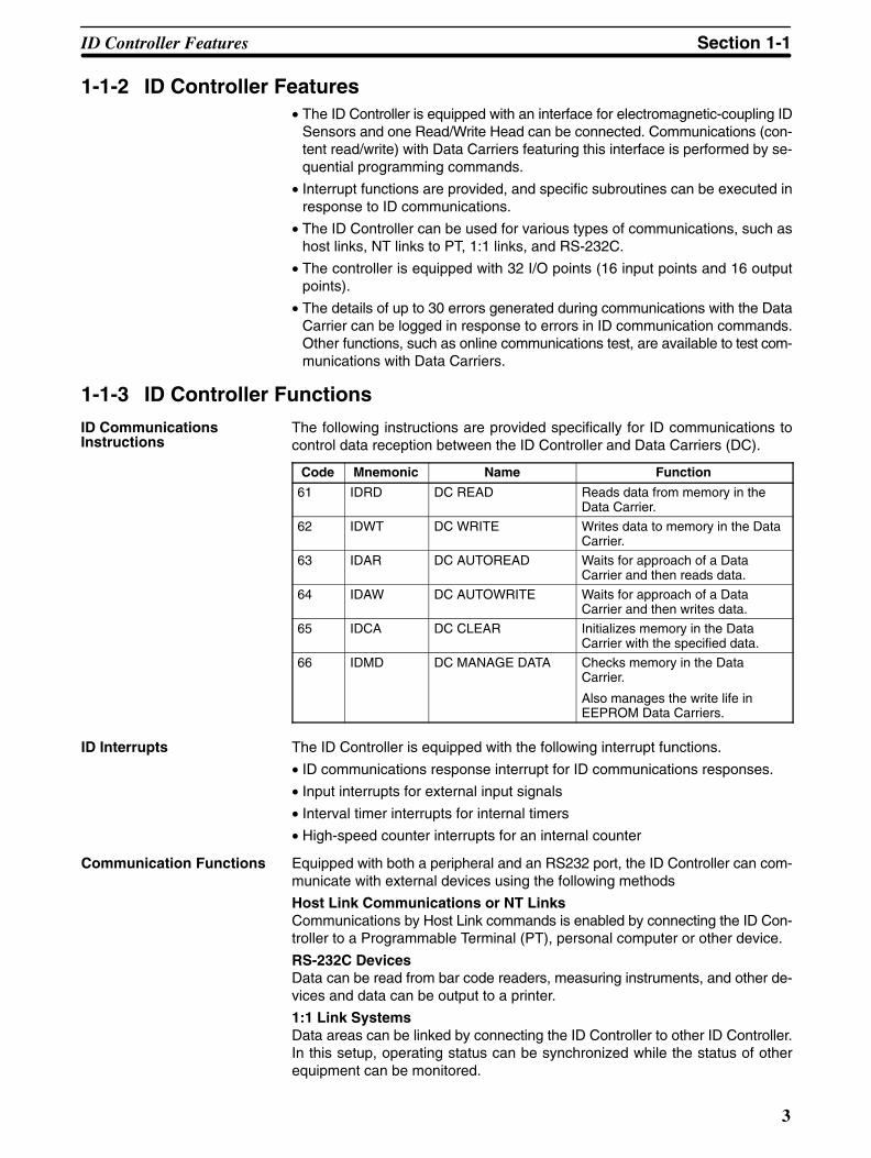
The following instructions are provided specifically for ID communications tocontrol data reception between the ID Controller and Data Carriers (DC).
Code Mnemonic Name Function
61 IDRD DC READ Reads data from memory in theData Carrier.
62 IDWT DC WRITE Writes data to memory in the DataCarrier.
63 IDAR DC AUTOREAD Waits for approach of a DataCarrier and then reads data.
64 IDAW DC AUTOWRITE Waits for approach of a DataCarrier and then writes data.
65 IDCA DC CLEAR Initializes memory in the DataCarrier with the specified data.
66 IDMD DC MANAGE DATA Checks memory in the DataCarrier.
Also manages the write life inEEPROM Data Carriers.
ID Interrupts The ID Controller is equipped with the following interrupt functions.
• ID communications response interrupt for ID communications responses.
• Input interrupts for external input signals
• Interval timer interrupts for internal timers
• High-speed counter interrupts for an internal counter
Communication Functions Equipped with both a peripheral and an RS232 port, the ID Controller can com-municate with external devices using the following methods
Host Link Communications or NT LinksCommunications by Host Link commands is enabled by connecting the ID Con-troller to a Programmable Terminal (PT), personal computer or other device.
RS-232C DevicesData can be read from bar code readers, measuring instruments, and other de-vices and data can be output to a printer.
1:1 Link SystemsData areas can be linked by connecting the ID Controller to other ID Controller.In this setup, operating status can be synchronized while the status of otherequipment can be monitored.
ID CommunicationsInstructions
ID Controller Features Section 1-1
4
32 I/O Points• Outputs: 16 contact outputs or 16 transistor outputs
• Inputs: 16 24-VDC inputs
ID Error Log The log of errors generated during ID communication is stored in the DM area inthe order generated (serial error log) or as statistical data by error type (errorstatistics log). The time that an error was generated can also be stored inmemory if a Memory Cassette equipped with clock functions is provided.
Serial and error statistics logs can be checked from a Programming Consoleconnected to the ID Controller.
ID Communication Errors
Errorcode
ProgrammingConsole message
Meaning
70 Data Carrier communications error.
71 Data mismatch.
72 Data Carrier missing.
7A Data Carrier address error.
7C Read/Write Head not connected.
7D Protection error.
PC Functions I/O and communication functions can be controlled with the ladder-diagram pro-gram in the PC. Advanced I/O instructions that input and output data with asingle instructions, macro instructions to call up subroutines, and differentialmonitoring to monitor changes (via LSS/SSS) in signals are also provided tohelp simplify programming and operation.
Note Refer to the CQM1 Programming and Operation Manuals for details on PC func-tions.
1-1-4 ID Controller Applications
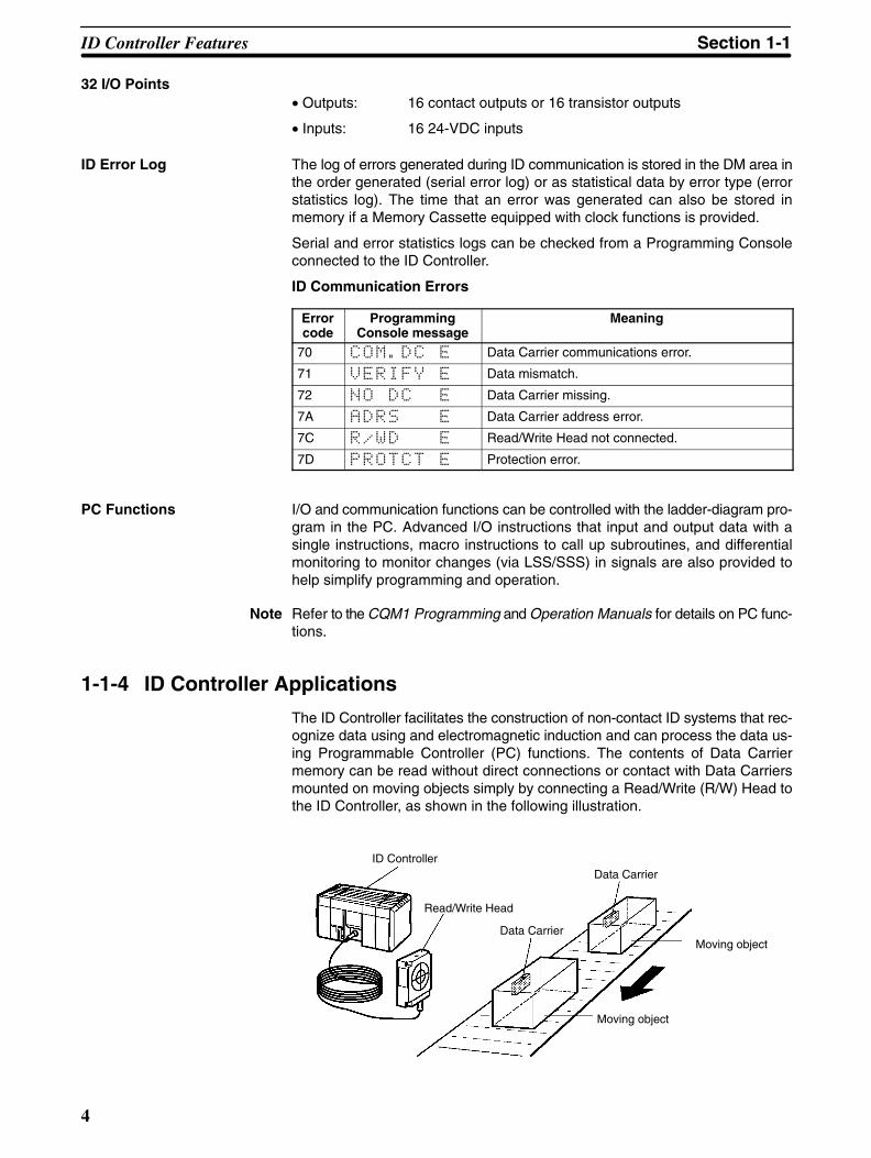
The ID Controller facilitates the construction of non-contact ID systems that rec-ognize data using and electromagnetic induction and can process the data us-ing Programmable Controller (PC) functions. The contents of Data Carriermemory can be read without direct connections or contact with Data Carriersmounted on moving objects simply by connecting a Read/Write (R/W) Head tothe ID Controller, as shown in the following illustration.
ID Controller
Read/Write Head
Data Carrier
Data Carrier
Moving object
Moving object
ID Controller Features Section 1-1

5
As a result, products or other articles can be distributed, and specific productscan be extracted automatically. (Refer to 7-4 Controlling Workpiece Flow.)
And since the ID Controller can write to Data Carriers, information such aswhether work was completed or work results can be recorded at any stage to theData Carrier of moving objects. (Refer to 7-1 Recording Data and 7-3 ManagingProduction Histories.)
Connecting Programmable Terminals (PTs), shown in the following illustration,to a ID Controller enables data confirmation, displays for work details applicablein the ID system and other capabilities. (Refer to 7-2 Displaying Worker Instruc-tions.)
ID Controller
Read/Write Head
Data Carrier
Moving object
Data Carrier
Moving object
PT
Data Recording The ID Controller and Programmable Terminal can also be used to record data inthe Data Carrier. Workers can record data in the Data Carrier with a few simpleoperations while confirming data details on a Programmable Terminal (PT)fnscreen.
ID Controller
Read/WriteHead
Data Carrier Workpiece
Data input
WorkerWorkpieces
Data Carrier
NT link to RS-232C portData registered for writing to Data Carrier PT
Worker Instructions The ID Controller can read work data from Data Carriers and display the resultson lamp to direct line workers.
ID Controller
Read/Write Head
Data CarrierWorkpiece
Part racks
Worker
Lamp control signals
Assembly End button
Work start lamp
#1 #2 #3 #4
#5 #6 #7 #8
ID Controller Features Section 1-1
6
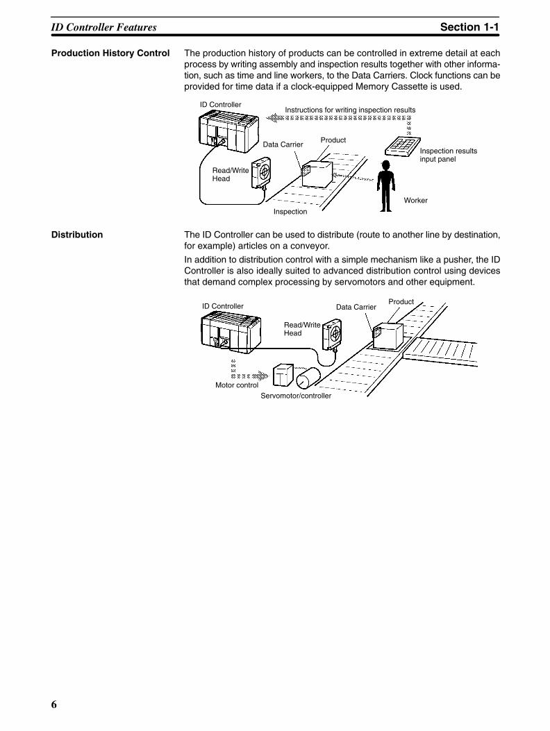
Production History Control The production history of products can be controlled in extreme detail at eachprocess by writing assembly and inspection results together with other informa-tion, such as time and line workers, to the Data Carriers. Clock functions can beprovided for time data if a clock-equipped Memory Cassette is used.
ID Controller
Read/WriteHead
Data CarrierProduct
Inspection
Worker
Inspection resultsinput panel
Instructions for writing inspection results
Distribution The ID Controller can be used to distribute (route to another line by destination,for example) articles on a conveyor.
In addition to distribution control with a simple mechanism like a pusher, the IDController is also ideally suited to advanced distribution control using devicesthat demand complex processing by servomotors and other equipment.
ID Controller
Read/WriteHead
Data CarrierProduct
Motor controlServomotor/controller
ID Controller Features Section 1-1
7
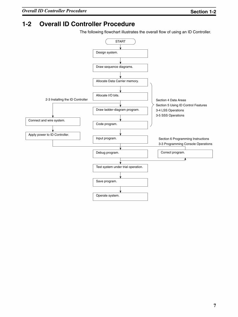
1-2 Overall ID Controller ProcedureThe following flowchart illustrates the overall flow of using an ID Controller.
Design system.
START
Draw sequence diagrams.
Allocate Data Carrier memory.
Allocate I/O bits.
Draw ladder-diagram program.
Code program.
Input program.
Debug program.
Test system under trial operation.
Save program.
Operate system.
Correct program.
Connect and wire system.
Apply power to ID Controller.
Section 4 Data Areas
Section 5 Using ID Control Features
3-4 LSS Operations
3-5 SSS Operations
2-3 Installing the ID Controller
Section 6 Programming Instructions
3-3 Programming Console Operations
Overall ID Controller Procedure Section 1-2
9
SECTION 2Hardware Components and Installation
This section describes the components that make up an ID Controller and the procedures necessary to install and mount an IDController.
2-1 Component Names and Functions 10. . . . . . . . . . . . . . . . . . . . . . . . . . . . . . . . . . . . . . . . . . . . 2-1-1 DIP Switch 10. . . . . . . . . . . . . . . . . . . . . . . . . . . . . . . . . . . . . . . . . . . . . . . . . . . . . . . 2-1-2 Indicators 11. . . . . . . . . . . . . . . . . . . . . . . . . . . . . . . . . . . . . . . . . . . . . . . . . . . . . . . . 2-1-3 ID Controller Operating Modes 12. . . . . . . . . . . . . . . . . . . . . . . . . . . . . . . . . . . . . . . 2-1-4 Memory Cassettes 13. . . . . . . . . . . . . . . . . . . . . . . . . . . . . . . . . . . . . . . . . . . . . . . . .
2-2 System Configuration and Installation 15. . . . . . . . . . . . . . . . . . . . . . . . . . . . . . . . . . . . . . . . . 2-2-1 Basic Configuration 15. . . . . . . . . . . . . . . . . . . . . . . . . . . . . . . . . . . . . . . . . . . . . . . . 2-2-2 Installation Precautions 16. . . . . . . . . . . . . . . . . . . . . . . . . . . . . . . . . . . . . . . . . . . . . 2-2-3 Terminal Blocks 18. . . . . . . . . . . . . . . . . . . . . . . . . . . . . . . . . . . . . . . . . . . . . . . . . . . 2-2-4 I/O Wiring Precautions 18. . . . . . . . . . . . . . . . . . . . . . . . . . . . . . . . . . . . . . . . . . . . . 2-2-5 I/O Specifications 21. . . . . . . . . . . . . . . . . . . . . . . . . . . . . . . . . . . . . . . . . . . . . . . . . 2-2-6 Connectable Devices 25. . . . . . . . . . . . . . . . . . . . . . . . . . . . . . . . . . . . . . . . . . . . . . . 2-2-7 Connecting External Devices via RS-232C Port 26. . . . . . . . . . . . . . . . . . . . . . . . . .
2-3 Installing the ID Controller 28. . . . . . . . . . . . . . . . . . . . . . . . . . . . . . . . . . . . . . . . . . . . . . . . . 2-3-1 Mounting the ID Controller 28. . . . . . . . . . . . . . . . . . . . . . . . . . . . . . . . . . . . . . . . . . 2-3-2 Wiring the Power Supply 30. . . . . . . . . . . . . . . . . . . . . . . . . . . . . . . . . . . . . . . . . . . . 2-3-3 Connecting the Read/Write Head 31. . . . . . . . . . . . . . . . . . . . . . . . . . . . . . . . . . . . .
10
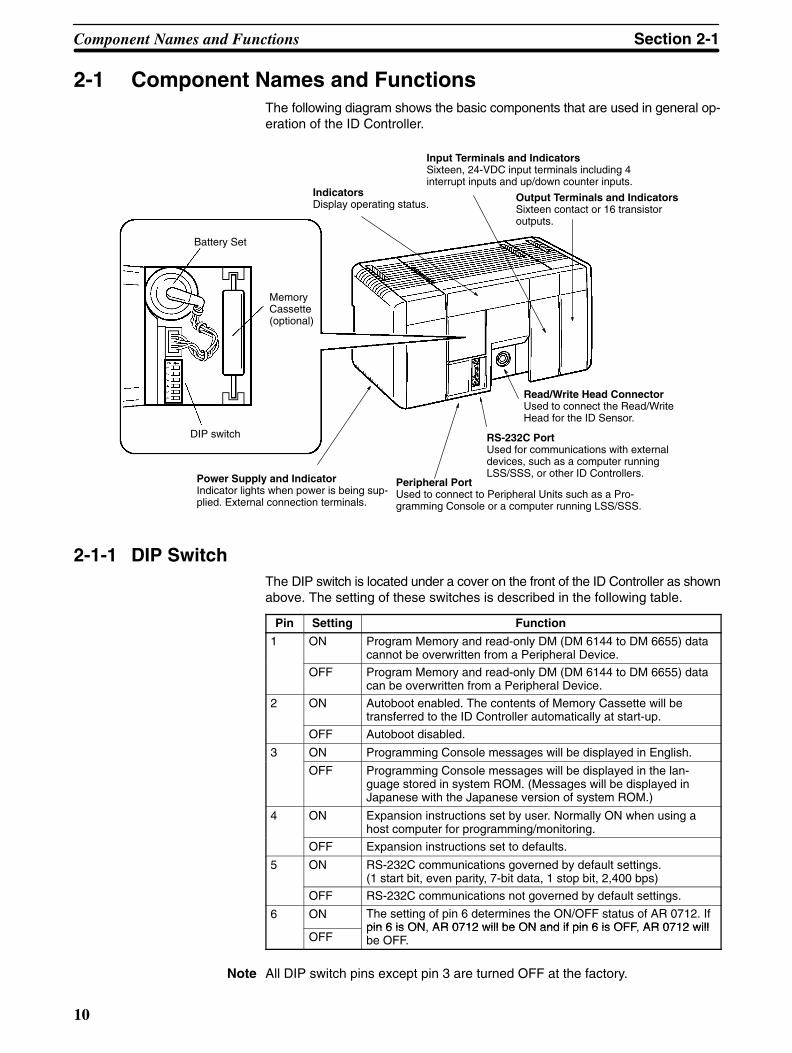
2-1 Component Names and FunctionsThe following diagram shows the basic components that are used in general op-eration of the ID Controller.
IndicatorsDisplay operating status.
RS-232C PortUsed for communications with externaldevices, such as a computer runningLSS/SSS, or other ID Controllers.
Peripheral PortUsed to connect to Peripheral Units such as a Pro-gramming Console or a computer running LSS/SSS.
DIP switch
Battery Set
MemoryCassette(optional)
Read/Write Head ConnectorUsed to connect the Read/WriteHead for the ID Sensor.
Input Terminals and IndicatorsSixteen, 24-VDC input terminals including 4interrupt inputs and up/down counter inputs.
Output Terminals and IndicatorsSixteen contact or 16 transistoroutputs.
Power Supply and IndicatorIndicator lights when power is being sup-plied. External connection terminals.
2-1-1 DIP SwitchThe DIP switch is located under a cover on the front of the ID Controller as shownabove. The setting of these switches is described in the following table.
Pin Setting Function
1 ON Program Memory and read-only DM (DM 6144 to DM 6655) datacannot be overwritten from a Peripheral Device.
OFF Program Memory and read-only DM (DM 6144 to DM 6655) datacan be overwritten from a Peripheral Device.
2 ON Autoboot enabled. The contents of Memory Cassette will betransferred to the ID Controller automatically at start-up.
OFF Autoboot disabled.
3 ON Programming Console messages will be displayed in English.
OFF Programming Console messages will be displayed in the lan-guage stored in system ROM. (Messages will be displayed inJapanese with the Japanese version of system ROM.)
4 ON Expansion instructions set by user. Normally ON when using ahost computer for programming/monitoring.
OFF Expansion instructions set to defaults.
5 ON RS-232C communications governed by default settings.(1 start bit, even parity, 7-bit data, 1 stop bit, 2,400 bps)
OFF RS-232C communications not governed by default settings.
6 ON The setting of pin 6 determines the ON/OFF status of AR 0712. Ifpin 6 is ON AR 0712 will be ON and if pin 6 is OFF AR 0712 will
OFFpin 6 is ON, AR 0712 will be ON and if pin 6 is OFF, AR 0712 willbe OFF.
Note All DIP switch pins except pin 3 are turned OFF at the factory.
Component Names and Functions Section 2-1
11
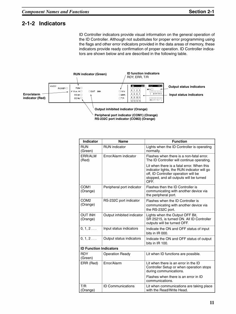
2-1-2 Indicators
ID Controller indicators provide visual information on the general operation ofthe ID Controller. Although not substitutes for proper error programming usingthe flags and other error indicators provided in the data areas of memory, theseindicators provide ready confirmation of proper operation. ID Controller indica-tors are shown below and are described in the following table.
Input status indicators
RUN indicator (Green)
Error/alarmindicator (Red)
Output inhibited indicator (Orange)
Peripheral port indicator (COM1) (Orange)RS-232C port indicator (COM2) (Orange)
Output status indicators
ID function indicatorsRDY, ERR, T/R
0 1 2 3
4 5 6 7
8 9 10 11
12 13 14 15
Indicator Name Function
RUN(Green)
RUN indicator Lights when the ID Controller is operatingnormally.
ERR/ALM(Red)
Error/Alarm indicator Flashes when there is a non-fatal error.The ID Controller will continue operating.
Lit when there is a fatal error. When thisindicator lights, the RUN indicator will gooff, ID Controller operation will bestopped, and all outputs will be turnedOFF.
COM1(Orange)
Peripheral port indicator Flashes then the ID Controller iscommunicating with another device viathe peripheral port.
COM2(Orange)
RS-232C port indicator Flashes when the ID Controller iscommunicating with another device viathe RS-232C port.
OUT INH(Orange)
Output inhibited indicator Lights when the Output OFF Bit,SR 25215, is turned ON. All ID Controlleroutputs will be turned OFF.
0, 1, 2 . . . Input status indicators Indicate the ON and OFF status of inputbits in IR 000.
0, 1, 2 . . . Output status indicators Indicate the ON and OFF status of outputbits in IR 100.
ID Function Indicators
RDY(Green)
Operation Ready Lit when ID functions are possible.
ERR (Red) Error/Alarm Lit when there is an error in the IDController Setup or when operation stopsduring communications.
Flashes when there is an error in IDcommunications.
T/R(Orange)
ID Communications Lit when communications are taking placewith the Read/Write Head.
Component Names and Functions Section 2-1
12
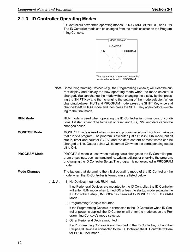
2-1-3 ID Controller Operating ModesID Controllers have three operating modes: PROGRAM, MONITOR, and RUN.The ID Controller mode can be changed from the mode selector on the Program-ming Console.
RUN
MONITOR
PROGRAM
Mode selector
The key cannot be removed when themode selector is set to PROGRAM.
Note Some Programming Devices (e.g., the Programming Console) will clear the cur-rent display and display the new operating mode when the mode selector ischanged. You can change the mode without changing the display by first press-ing the SHIFT Key and then changing the setting of the mode selector. Whenchanging between RUN and PROGRAM mode, press the SHIFT Key once andchange to MONITOR mode and then press the SHIFT Key again before switch-ing to the final mode.
RUN mode is used when operating the ID Controller in normal control condi-tions. Bit status cannot be force set or reset, and SVs, PVs, and data cannot bechanged online.
MONITOR mode is used when monitoring program execution, such as making atrial run of a program. The program is executed just as it is in RUN mode, but bitstatus, timer and counter SV/PV, and the data content of most words can bechanged online. Output points will be turned ON when the corresponding outputbit is ON.
PROGRAM mode is used when making basic changes to the ID Controller pro-gram or settings, such as transferring, writing, editing, or checking the program,or changing the ID Controller Setup. The program is not executed in PROGRAMmode.
Mode Changes The factors that determine the initial operating mode of the ID Controller (themode when the ID Controller is turned on) are listed below.
1, 2, 3... 1. No Devices mounted: RUN mode
If no Peripheral Devices are mounted to the ID Controller, the ID Controllerwill enter RUN mode when turned ON unless the startup mode setting in theID Controller Setup (DM 6600) has been set to MONITOR or PROGRAMMode.
2. Programming Console mounted:
If the Programming Console is connected to the ID Controller when ID Con-troller power is applied, the ID Controller will enter the mode set on the Pro-gramming Console’s mode selector.
3. Other Peripheral Device mounted:
If a Programming Console is not mounted to the ID Controller, but anotherPeripheral Device is connected to the ID Controller, the ID Controller will en-ter PROGRAM mode.
RUN Mode
MONITOR Mode
PROGRAM Mode
Component Names and Functions Section 2-1

!
13
If the ID Controller power supply is already turned on when a Peripheral Deviceis attached to the ID Controller, the ID Controller will stay in the same mode it wasin before the peripheral device was attached. If the Programming Console isconnected, the ID Controller will enter the mode set on the Programming Con-sole’s mode selector once the password has been entered.
2-1-4 Memory CassettesSix Memory Cassettes are available as accessories to store the program or IDController Setup. The following CQM1 Memory Cassettes are used for ID Con-trollers.
Note When pin 2 of the ID Controller’s DIP switch is ON, the contents of the MemoryCassette will be transferred to the ID Controller automatically at start-up.
Memory Clock Function Model CommentsEEPROM No CQM1-ME04K The Programming Console is
used to write to EEPROMYes CQM1-ME04R
used to write to EEPROM.(4K words)
No CQM1-ME08K The Programming Console isused to write to EEPROM
Yes CQM1-ME08Rused to write to EEPROM.(8K words)
EPROM No CQM1-MP08K A PROM Writer is used to writeEPROMYes CQM1-MP08R to EPROM.
Memory Cassette Installation Follow the procedure below to install a Memory Cassette in the ID Controller.
Caution Always turn off power to the ID Controller before installing or removing a MemoryCassette.
1, 2, 3... 1. Remove the mounting bracket from inside the memory cassette compart-ment.
2. Slide the Memory Cassette into the ID Controller on the tracks provided.Press the Memory Cassette in so that the connectors fit securely.
Memory cassette
3. Replace the bracket as shown below and tighten the screw.
Mounting bracket
Component Names and Functions Section 2-1
!
14
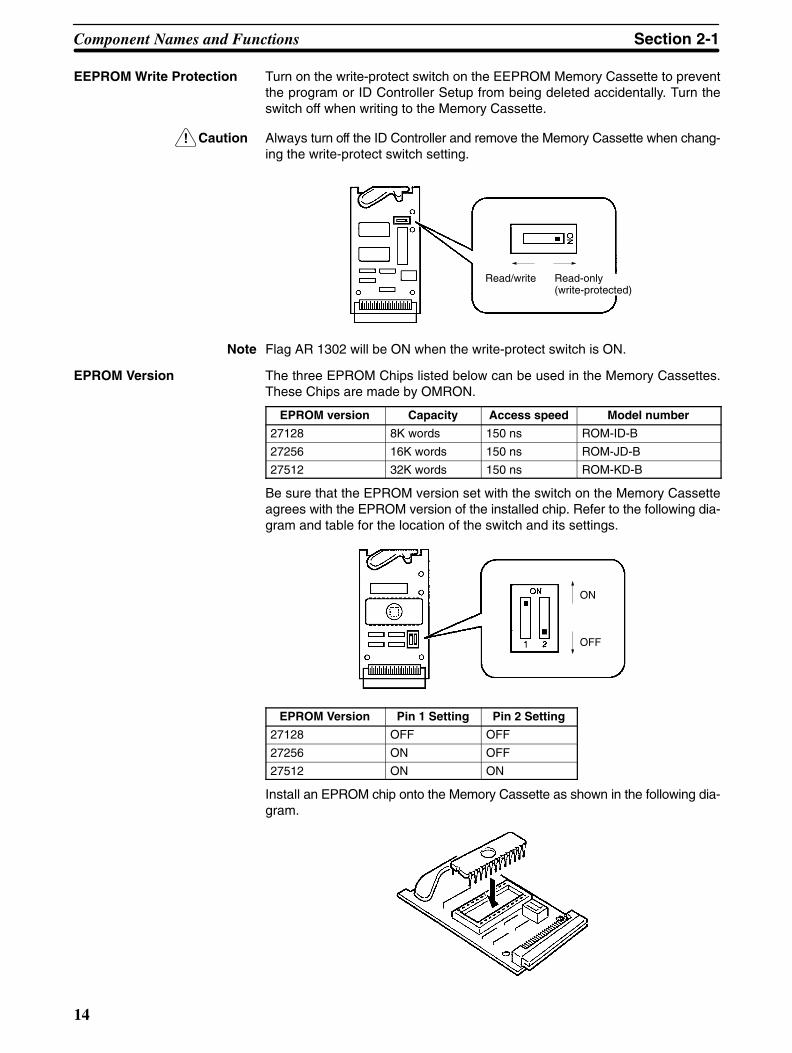
EEPROM Write Protection Turn on the write-protect switch on the EEPROM Memory Cassette to preventthe program or ID Controller Setup from being deleted accidentally. Turn theswitch off when writing to the Memory Cassette.
Caution Always turn off the ID Controller and remove the Memory Cassette when chang-ing the write-protect switch setting.
Read/write Read-only(write-protected)
Note Flag AR 1302 will be ON when the write-protect switch is ON.
EPROM Version The three EPROM Chips listed below can be used in the Memory Cassettes.These Chips are made by OMRON.
EPROM version Capacity Access speed Model number
27128 8K words 150 ns ROM-ID-B
27256 16K words 150 ns ROM-JD-B
27512 32K words 150 ns ROM-KD-B
Be sure that the EPROM version set with the switch on the Memory Cassetteagrees with the EPROM version of the installed chip. Refer to the following dia-gram and table for the location of the switch and its settings.
ON
OFF
EPROM Version Pin 1 Setting Pin 2 Setting
27128 OFF OFF
27256 ON OFF
27512 ON ON
Install an EPROM chip onto the Memory Cassette as shown in the following dia-gram.
Component Names and Functions Section 2-1
15
2-2 System Configuration and Installation
2-2-1 Basic Configuration
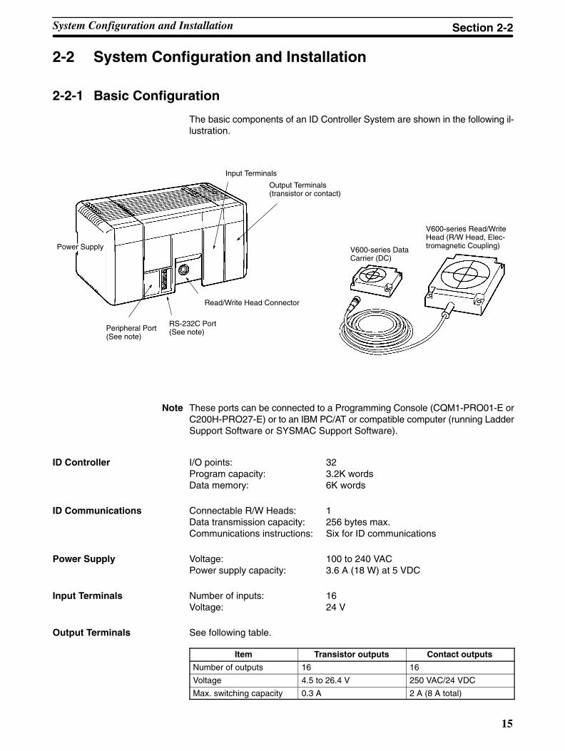
The basic components of an ID Controller System are shown in the following il-lustration.
RS-232C Port(See note)Peripheral Port
(See note)
Read/Write Head Connector
Input Terminals
Output Terminals (transistor or contact)
V600-series DataCarrier (DC)
V600-series Read/WriteHead (R/W Head, Elec-tromagnetic Coupling)Power Supply
Note These ports can be connected to a Programming Console (CQM1-PRO01-E orC200H-PRO27-E) or to an IBM PC/AT or compatible computer (running LadderSupport Software or SYSMAC Support Software).
ID Controller I/O points: 32Program capacity: 3.2K wordsData memory: 6K words
ID Communications Connectable R/W Heads: 1Data transmission capacity: 256 bytes max.Communications instructions: Six for ID communications
Power Supply Voltage: 100 to 240 VACPower supply capacity: 3.6 A (18 W) at 5 VDC
Input Terminals Number of inputs: 16Voltage: 24 V
Output Terminals See following table.
Item Transistor outputs Contact outputs
Number of outputs 16 16
Voltage 4.5 to 26.4 V 250 VAC/24 VDC
Max. switching capacity 0.3 A 2 A (8 A total)
System Configuration and Installation Section 2-2
!
16
2-2-2 Installation PrecautionsThis section provides precautions for installing the ID Controller.
Caution Static electricity can damage ID Controller components. Your body can carry anelectrostatic charge, especially when the humidity is low. Before touching the IDController, be sure to first touch a grounded metallic object, such as a metal wa-ter pipe, in order to discharge any static build-up.
Ambient Conditions Do not install the ID Controller in any of the following locations. Doing so will af-fect ID Controller life and may affect operating performance.
• Locations subject to ambient temperatures lower than 0°C or higher than55°C, or 0°C to 45°C when a Programming Console is used.
• Locations subject to drastic temperature changes or condensation.
• Locations subject to ambient humidity lower than 10% or higher than 90%.
• Locations subject to corrosive or flammable gases.
• Locations subject to excessive dust (especially iron dust) or chloride.
• Locations that would subject the ID Controller to direct shock or vibration.
• Locations that would subject the ID Controller to water, oil, or chemical re-agents.
• Locations exposed to direct sunlight.
• Do not install the ID Controller over heaters, transformers, high-capacity resis-tors, or other devices that generate heat.
High-voltage Equipment To maintain safe operating conditions, locate the ID Controller as far away fromhigh-voltage equipment as possible.
Clearance The ID Controller needs to have sufficient room to allow for I/O wiring, and addi-tional room to ensure that the I/O wiring does not hamper cooling or does notstrike the cover to the control panel when it is closed. As a general rule, allow atleast 20 mm above and below the ID Controller.
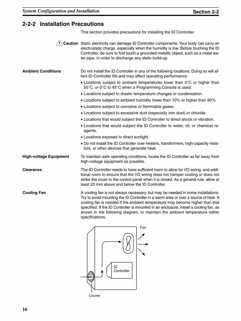
Cooling Fan A cooling fan is not always necessary, but may be needed in some installations.Try to avoid mounting the ID Controller in a warm area or over a source of heat. Acooling fan is needed if the ambient temperature may become higher than thatspecified. If the ID Controller is mounted in an enclosure, install a cooling fan, asshown in the following diagram, to maintain the ambient temperature withinspecifications.
ID Controller
Fan
Louver
System Configuration and Installation Section 2-2
17
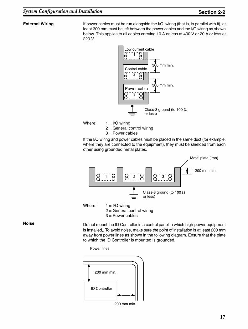
External Wiring If power cables must be run alongside the I/O wiring (that is, in parallel with it), atleast 300 mm must be left between the power cables and the I/O wiring as shownbelow. This applies to all cables carrying 10 A or less at 400 V or 20 A or less at220 V.
Low current cable
Control cable
Power cable
300 mm min.
300 mm min.
1
2
3
Class-3 ground (to 100 Ωor less)
Where: 1 = I/O wiring2 = General control wiring3 = Power cables
If the I/O wiring and power cables must be placed in the same duct (for example,where they are connected to the equipment), they must be shielded from eachother using grounded metal plates.
Metal plate (iron)
1 2 3
200 mm min.
Class-3 ground (to 100 Ωor less)
Where: 1 = I/O wiring2 = General control wiring3 = Power cables
Do not mount the ID Controller in a control panel in which high-power equipmentis installed,. To avoid noise, make sure the point of installation is at least 200 mmaway from power lines as shown in the following diagram. Ensure that the plateto which the ID Controller is mounted is grounded.
ID Controller
200 mm min.
200 mm min.
Power lines
Noise
System Configuration and Installation Section 2-2

!
!
!
18
Mounting Direction Always mount the ID Controller with the cooling vents facing up. Never mount iton it’s side or end.
Correct Wrong Wrong
2-2-3 Terminal BlocksThe I/O Controller’s terminal blocks are removable. Be sure that the connectortabs are in the locked position, as shown in the following diagram.
To remove the terminal block, push the connector tabs to the sides and lift theterminal block off of the connector, as shown in the following diagram.
Open the tabs as widelyas necessary.
Crimp connectors for I/O wiring should be less than 6.2 mm wide (M3).
6.2 mm max.6.2 mm max.
Caution Forked crimp connectors are required by UL and CSA standards.
2-2-4 I/O Wiring PrecautionsThe following must be considered when connecting electrical devices to I/O ter-minals: leakage currents, inrush currents, noise, and inductive loads
Caution Tighten the terminal screws to a torque of 0.5 to 0.6 Nm.
WARNING Do not apply voltages exceeding the maximum permissible input voltage toinputs nor voltages exceeding the switching capacity to output. Doing so mayresult in damage or destruction of the ID Controller or may result in fire.
Leakage Current (24 VDC) A leakage current can cause false inputs when using 2-wire sensors (proximityswitches or photoelectric switches) or limit switches with LEDs on 24-VDC in-puts.
System Configuration and Installation Section 2-2
19
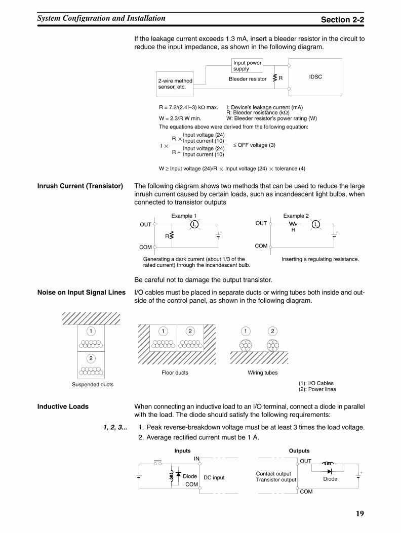
If the leakage current exceeds 1.3 mA, insert a bleeder resistor in the circuit toreduce the input impedance, as shown in the following diagram.
R IDSC
Input powersupply
Bleeder resistor2-wire methodsensor, etc.
R = 7.2/(2.4I–3) kΩ max.
W = 2.3/R W min.
I: Device’s leakage current (mA)R: Bleeder resistance (kΩ)W: Bleeder resistor’s power rating (W)
The equations above were derived from the following equation:
W ≥ Input voltage (24)/R Input voltage (24) tolerance (4)
I R
Input voltage (24)Input current (10)
R +Input voltage (24)Input current (10)
≤ OFF voltage (3)
Inrush Current (Transistor) The following diagram shows two methods that can be used to reduce the largeinrush current caused by certain loads, such as incandescent light bulbs, whenconnected to transistor outputs
R
OUT
COM
OUT
COM
R
Example 1 Example 2
Generating a dark current (about 1/3 of therated current) through the incandescent bulb.
Inserting a regulating resistance.
Be careful not to damage the output transistor.
Noise on Input Signal Lines I/O cables must be placed in separate ducts or wiring tubes both inside and out-side of the control panel, as shown in the following diagram.
Suspended ducts
Floor ducts Wiring tubes
(1): I/O Cables(2): Power lines
ÉÉÉÉÉÉÉÉÉÉÉÉÉÉÉÉÉÉÉÉÉÉÉÉÉÉÉÉÉÉÉÉÉÉÉÉÉÉÉÉ
1
2
ÉÉÉÉÉÉÉÉÉÉÉÉ 1 2
ÉÉÉÉÉÉÉÉÉÉÉÉ
1 2
Inductive Loads When connecting an inductive load to an I/O terminal, connect a diode in parallelwith the load. The diode should satisfy the following requirements:
1, 2, 3... 1. Peak reverse-breakdown voltage must be at least 3 times the load voltage.
2. Average rectified current must be 1 A.
IN
COM
OUT
COM
Diode DC inputContact outputTransistor output Diode
Inputs Outputs
System Configuration and Installation Section 2-2

20
Wiring I/O Terminal When connecting an external device with a DC output to a DC input terminal,wire the device as shown in the following table.
Device output type Circuit Diagram (External device on left; input terminals on right
Contact output
IN
COM(+)
Relay
NPN open collector
0 V
+
IN
COM(+)
SensorSensor powersupply
Output
NPN current output
Sensor powersupply0 V
+
IN
COM(+)
Constant currentcircuit
Output
Use the same power supplyfor the input and sensor.
+
PNP current outputSensor powersupply
COM(–)0 V
IN
+
Output
Voltage output
Sensor powersupply
IN
COM (+)
0 V
Output
System Configuration and Installation Section 2-2

21
2-2-5 I/O Specifications
24-VDC Inputs (16 pts)
Item Specification
Model IDSC-C1D-A-E
Input Voltage 24 VDC +10%/–15%
Input Impedance IN4 and IN5: 2.2 kΩ; other inputs: 3.9 kΩInput Current IN4 and IN5: 10 mA typical; other inputs: 6 mA typical (at 24 VDC)
ON Voltage 14.4 VDC min.
OFF Voltage 5.0 VDC max.
ON Delay Default: 8 ms max. (can be set between 1 and 128 ms in ID Controller Setup; see note)
OFF Delay Default: 8 ms max. (can be set between 1 and 128 ms in ID Controller Setup; see note)
No. of Inputs 16 points (16 inputs/common, 1 circuit)
Circuit Configuration
560 Ω
IN0toIN15
COM
3.9 kΩ(2.2 kΩ)
InputLED
InternalCircuits
Note Figures in parentheses are for IN4 and IN5.The input power supply polarity may be con-nected in either direction.
Terminal ConnectionsB0
0
1A0
B12
3A1
B24
5A2
B36
7A3
B48
9A4
B510
11A5
B612
13A6
B714
15A7
B8COM
A8COM–
–
Note IN0 through IN3 can be set for use as input interrupts in the ID Controller Setup.The ON and OFF delays for input interrupts are fixed at 0.1 ms max. and 0.5 msmax., respectively. IN4 through IN6 can be set for use as high-speed counterinterrupts. The delays for high-speed counter interrupts are shown in the follow-ing table.
Input Increment input mode Differential phase mode
IN4 (A) 5 KHz 2.5 KHz
IN5 (B) Normal input
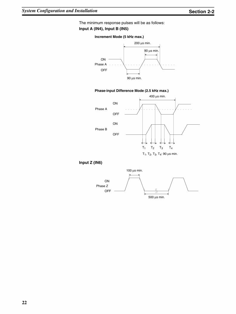
IN6 (Z) ON: 100 s min. required; OFF delay: 500 s min. required
System Configuration and Installation Section 2-2
22
The minimum response pulses will be as follows:
Input A (IN4), Input B (IN5)
Increment Mode (5 kHz max.)
200 µs min.
90 µs min.
90 µs min.
Phase-input Difference Mode (2.5 kHz max.)
400 µs min.
T1, T2, T3, T4: 90 µs min.
ON
OFF
ON
OFF
Phase A
T1 T2 T3 T4
ON
OFF
Phase B
Phase A
Input Z (IN6)
100 µs min.
500 µs min.
ON
OFF
Phase Z
System Configuration and Installation Section 2-2
23
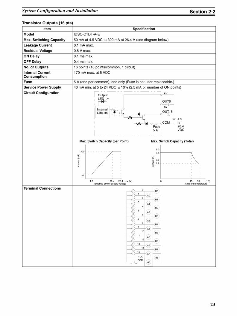
Transistor Outputs (16 pts)Item Specification
Model IDSC-C1DT-A-E
Max. Switching Capacity 50 mA at 4.5 VDC to 300 mA at 26.4 V (see diagram below)
Leakage Current 0.1 mA max.
Residual Voltage 0.8 V max.
ON Delay 0.1 ms max.
OFF Delay 0.4 ms max.
No. of Outputs 16 points (16 points/common, 1 circuit)
Internal CurrentConsumption
170 mA max. at 5 VDC
Fuse 5 A (one per common), one only (Fuse is not user replaceable.)
Service Power Supply 40 mA min. at 5 to 24 VDC 10% (2.5 mA number of ON points)
Circuit Configuration
to
+V
Fuse5 A
OUT0
OutputLED
InternalCircuits
COM
OUT15
4.5to26.4VDC
4.5 20.4 26.4 0 45 55
300
50
5.0
4.8
3.02.8
Max. Switch Capacity (per Point)
+V (V)
Ic m
ax. (
mA
)
Max. Switch Capacity (Total)
(C)
Ic m
ax. (
A)
External power supply voltage Ambient temperature
Terminal ConnectionsB0
0
1A0
B12
3A1
B24
5A2
B36
7
B48
9A4
B510
11A5
B612
13A6
B714
15A7
B8
A8
A3
COM–
+DC
System Configuration and Installation Section 2-2

24
Contact Outputs (16 pts)Item Specification
Model IDSC-C1DR-A-E
Max. SwitchingCapacity
2 A, 250 VAC (cosφ= 1)2 A, 250 VAC (cosφ= 0.4)2 A, 24 VDC (8 A total)
Min. SwitchingCapacity
10 mA, 5 VDC
Relay G6D-1AService Life ofRelay
Electrical: 300,000 operations (resistive load) 100,000 operations (inductive load)Mechanical: 20,000,000 operations
ON Delay 10 ms max.OFF Delay 5 ms max.No. of Outputs 16 points (16 points/common, 1 circuit))Internal CurrentConsumption
850 mA max. at 5 VDC
CircuitConfiguration
OUT0OutputLED
InternalCircuits
COMMaximum250 VAC: 2 A24 VDC: 2 A
OUT15
TerminalConnections B0
0
1A0
B12
3A1
B24
5A2
B36
7
B48
9A4
B510
11A5
B612
13A6
B714
15A7
B8
A8
A3
COM
COM
System Configuration and Installation Section 2-2

25
2-2-6 Connectable Devices
Memory Model Clock CapacityEEPROM CQM1-ME04K No 4K words
CQM1-ME04R Yes
CQM1-ME08K No 8K words
CQM1-ME08R Yes
EPROM (socket only) CQM1-MP08K No 8K words( y)
CQM1-MP08R Yes
Name Model
Battery Set 3G2A9-BAT08
Name Model CommentsRead/Write Head V600-H07 30.5 m max.
V600-H11/H51/H52 50.5 m max.
Data Carrier V600-DR Built-in lithium battery
V600-DP No battery
Note Not all combinations of Data Carrier and Read/Write Head are possible. Refer tothe following manuals for details: V600 FA ID Sensor Serial Interface OperationManual (Z44-E1-2) and V600 FA ID Sensor Parallel Interface Operation Manual(Z45-E1-2).
Programming Devices The ID Controller can be programmed and operated either from an IBM PC/ATor compatible running the LSS/SSS or from a Programming Console.
Connect the computer using the illustrated cables. The computer must run theLadder Support Software (LSS) version 3 or later (on 3.5” floppy disks:C500-SF312-EV3; on 5” floppy disks: C500-SF711-EV3), or SYSMAC SupportSoftware (SSS) (C500-ZL3AT1-E).
RS-232C connector
RS-232C connector
CQM1-CIF02 Connecting Cable
RS-232C cable (provided by user)
Peripheral port
RS-232C port
Memory Cassettes
Battery Set
Read/Write Heads and DataCarriers
System Configuration and Installation Section 2-2

26
Connect the Programming Console using the illustrated cables.
Use enclosed cable.
Connecting Cable:C200H-CN222 (2 m)C200H-CN422 (4 m)
Peripheral port
Peripheral port
CQM1 Programming ConsoleCQM1-PRO01-E
C-series Programming ConsoleC200H-PRO27-E
2-2-7 Connecting External Devices via RS-232C Port
Various types of devices can be connected to the ID Controller via the RS-232C.A few examples are shown in the following illustration.
Personal computer
PT
Bar Code Reader
Printer
RS-232C DevicesHost link 1 to 1 link
System Configuration and Installation Section 2-2
27
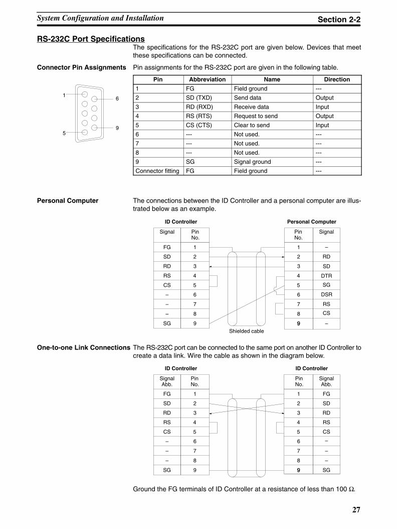
RS-232C Port SpecificationsThe specifications for the RS-232C port are given below. Devices that meetthese specifications can be connected.
Connector Pin Assignments Pin assignments for the RS-232C port are given in the following table.
Pin Abbreviation Name Direction
1 FG Field ground ---
2 SD (TXD) Send data Output
3 RD (RXD) Receive data Input
4 RS (RTS) Request to send Output
5 CS (CTS) Clear to send Input
6 --- Not used. ---
7 --- Not used. ---
8 --- Not used. ---
9 SG Signal ground ---
Connector fitting FG Field ground ---
Personal Computer The connections between the ID Controller and a personal computer are illus-trated below as an example.
1
2
3
4
5
6
FG
SD
RD
RS
CS
–
–
–
SG
7
8
9
1
2
3
4
5
6
7
8
9
SD
RD
RS
CS
DSR
SG
–9
DTR
ID Controller Personal Computer
SignalPinNo.
Signal PinNo.
Shielded cable
–
One-to-one Link Connections The RS-232C port can be connected to the same port on another ID Controller tocreate a data link. Wire the cable as shown in the diagram below.
1
2
3
4
5
6
FG
SD
RD
RS
CS
–
–
–
SG
7
8
9
1
2
3
4
5
6
7
8
9
FG
SD
RD
RS
CS
–
–
SG9
ID Controller ID Controller
SignalAbb.
PinNo.
SignalAbb.
PinNo.
–
Ground the FG terminals of ID Controller at a resistance of less than 100 Ω.
System Configuration and Installation Section 2-2
5
1
9
6
28
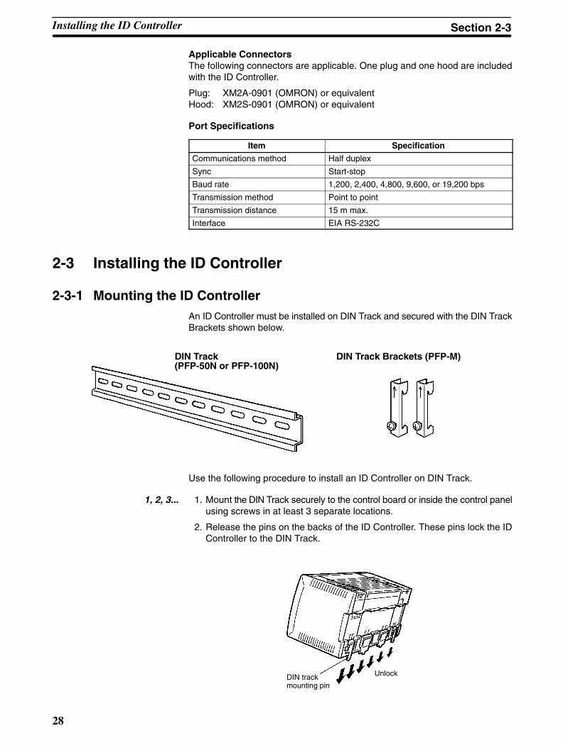
Applicable ConnectorsThe following connectors are applicable. One plug and one hood are includedwith the ID Controller.
Plug: XM2A-0901 (OMRON) or equivalentHood: XM2S-0901 (OMRON) or equivalent
Port Specifications
Item Specification
Communications method Half duplex
Sync Start-stop
Baud rate 1,200, 2,400, 4,800, 9,600, or 19,200 bps
Transmission method Point to point
Transmission distance 15 m max.
Interface EIA RS-232C
2-3 Installing the ID Controller
2-3-1 Mounting the ID ControllerAn ID Controller must be installed on DIN Track and secured with the DIN TrackBrackets shown below.
DIN Track (PFP-50N or PFP-100N)
DIN Track Brackets (PFP-M)
Use the following procedure to install an ID Controller on DIN Track.
1, 2, 3... 1. Mount the DIN Track securely to the control board or inside the control panelusing screws in at least 3 separate locations.
2. Release the pins on the backs of the ID Controller. These pins lock the IDController to the DIN Track.
DIN trackmounting pin
Unlock
Installing the ID Controller Section 2-3
29
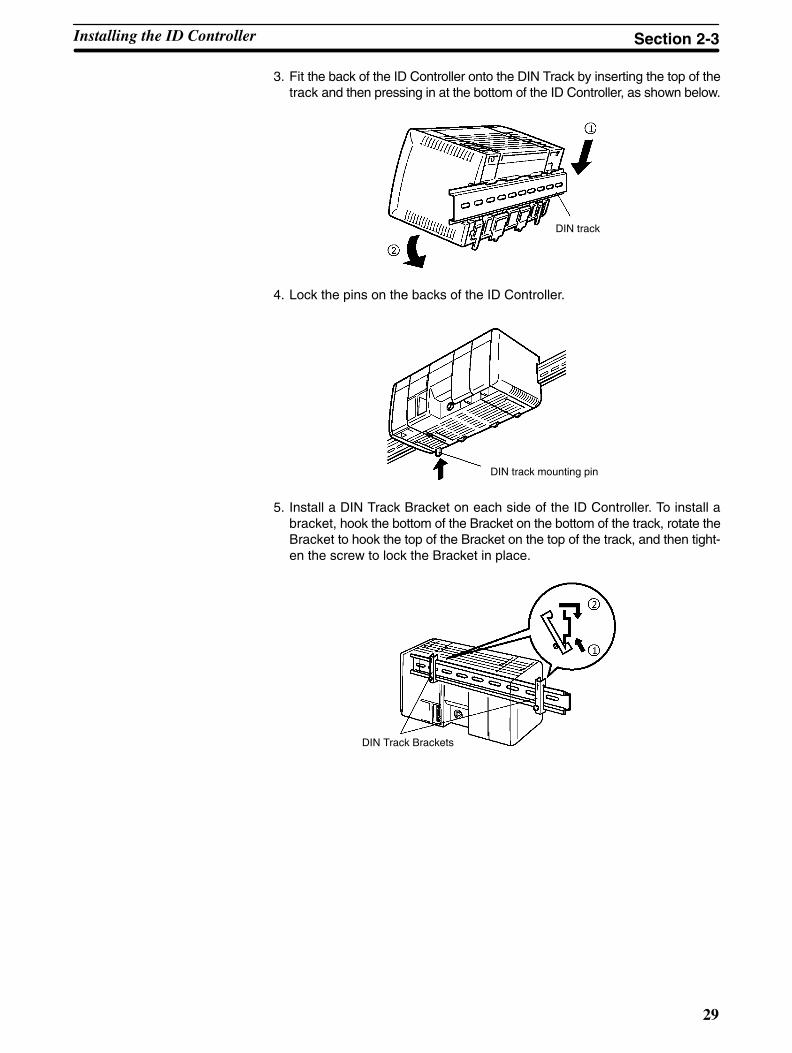
3. Fit the back of the ID Controller onto the DIN Track by inserting the top of thetrack and then pressing in at the bottom of the ID Controller, as shown below.
DIN track
4. Lock the pins on the backs of the ID Controller.
DIN track mounting pin
5. Install a DIN Track Bracket on each side of the ID Controller. To install abracket, hook the bottom of the Bracket on the bottom of the track, rotate theBracket to hook the top of the Bracket on the top of the track, and then tight-en the screw to lock the Bracket in place.
DIN Track Brackets
Installing the ID Controller Section 2-3

!
!
!
!
30
2-3-2 Wiring the Power SupplyThe following diagram shows the proper connection to an AC power supply. TheAC voltage should be between 100 and 240 VAC with an allowable range of 85 to264 VAC.
An insulating transformer greatlyreduces the noise that may beinduced between the power line andground. Do not ground the secondaryside of the insulating transformer.
The cross-sectional area of each wire must be 2 mm2 min.
Twist the wires.
Insulating transformer
Breaker
AC power supply
Caution Be sure that the AC power supply voltage remains within the allowed fluctuationrange of 85 to 264 VAC. Exceeding this range may destroy the ID Controller.
Wire the grounding wires according to the diagram shown below. The ID Con-troller with the lot number Z5 manufactured in December 1995 and later isprovided with the LG-GR short-circuit bar and the DIN-track cable.Terminal Block for External ConnectionsThe following diagram shows the terminal blocks for the external power supply.
LG
GR
ACinput
Use an AC power supplybetween 100 and 240 VAC.
Noise filter neutral terminal
Protective earth terminal
The wire used should be at least 2 mm2. Provide the grounding point as close tothe ID Controller as possible.
WARNING LG: Noise filter neutral terminal. Short-circuit the LG terminal and GR terminalsusing the attached short-circuit bar and ground them at a resistance of less than100 Ω to reduce noise and prevent electric shock.
WARNING GR: Protective earth terminal. Connect to a separate ground wire of at least 2 mm2 toground the terminal at a resistance of less than 100 Ω to prevent electric shock.
Caution Avoid sharing the grounding wire with other equipment or attaching to the beamof a building, otherwise it may cause an adverse effect.
ID Controller Otherequipment ID Controller Other
equipment
Correct Incorrect
Wiring Precautions forGround Wires
Installing the ID Controller Section 2-3

!
!
31
In order to improve the Electro Magnetic Compatibility (EMC), connect the LGterminal to the screw on the end plate using the supplied DIN-track connectingcable.
DIN-track cable (Supplied withthe ID Controller)
Short-circuit bar (Supplied with the ID Controller)
Grounding wire (Use a wire of at least 2 mm2
to ground at a resistance ofless than 100 Ω.)
Note Definition of EMC:The EMC refers to the capacity of equipment represented in terms of emission,which indicates the degree to which electromagnetic waves produced by equip-ment do not affect other communications equipment, and also in terms of immu-nity, which indicates the degree of resistance against electromagnetic distur-bance.
Crimp Connectors Crimp connectors for the power supply should be less than 7 mm wide (M3.5).
7 mm max.7 mm max.
Caution Forked crimp connectors are required by UL and CSA standards.
2-3-3 Connecting the Read/Write Head
Connection Use the following procedure to connect the Read/Write Head.
1, 2, 3... 1. Hold on to the rubber molding at the connector of the Read/Write Head andalign it with the keyed slot on the connector on the ID Controller.
2. Press in firmly on the connector until it clicks into place.
Removal To remove the connector, hold onto the ring on the connector and pull straightout.
Caution Do not pull on the rubber molding. The Read/Write Head connector cable cannotbe removed by pulling out on the rubber molding; you must hold onto the slidingring. If you pull on the rubber molding, you may damage the connector or breakconnections inside the cable.
Note Refer to the following manuals for details on installing Read/Write Heads andData Carriers: V600 FA ID Sensor Serial Interface Operation Manual (Z44-E1-2)and V600 FA ID Sensor Parallel Interface Operation Manual (Z45-E1-2)
Installing the ID Controller Section 2-3

33
SECTION 3Programming Device Operations
This section describes the Programming Console, Ladder Support Software (LSS) Operations, and SYSMAC Support Soft-ware (SSS) Operations used with an ID Controller System.
3-1 Applicable Programming Devices 34. . . . . . . . . . . . . . . . . . . . . . . . . . . . . . . . . . . . . . . . . . . . 3-2 Programming Console Preparations 34. . . . . . . . . . . . . . . . . . . . . . . . . . . . . . . . . . . . . . . . . . . 3-3 Programming Console Operations 37. . . . . . . . . . . . . . . . . . . . . . . . . . . . . . . . . . . . . . . . . . . .
3-3-1 Testing ID Communications 37. . . . . . . . . . . . . . . . . . . . . . . . . . . . . . . . . . . . . . . . . 3-3-2 Reading the ID Error Log 38. . . . . . . . . . . . . . . . . . . . . . . . . . . . . . . . . . . . . . . . . . . 3-3-3 Clearing Memory 39. . . . . . . . . . . . . . . . . . . . . . . . . . . . . . . . . . . . . . . . . . . . . . . . . . 3-3-4 Reading/Clearing Error Messages 40. . . . . . . . . . . . . . . . . . . . . . . . . . . . . . . . . . . . . 3-3-5 Buzzer Operation 41. . . . . . . . . . . . . . . . . . . . . . . . . . . . . . . . . . . . . . . . . . . . . . . . . . 3-3-6 Reading and Changing Expansion Instructions 41. . . . . . . . . . . . . . . . . . . . . . . . . . . 3-3-7 Reading and Changing the Clock 42. . . . . . . . . . . . . . . . . . . . . . . . . . . . . . . . . . . . . 3-3-8 Setting and Reading a Program Memory Address 43. . . . . . . . . . . . . . . . . . . . . . . . . 3-3-9 Inserting and Deleting Instructions 44. . . . . . . . . . . . . . . . . . . . . . . . . . . . . . . . . . . . 3-3-10 Entering or Editing Programs 45. . . . . . . . . . . . . . . . . . . . . . . . . . . . . . . . . . . . . . . . 3-3-11 Checking the Program 47. . . . . . . . . . . . . . . . . . . . . . . . . . . . . . . . . . . . . . . . . . . . . . 3-3-12 Bit, Digit, Word Monitor 47. . . . . . . . . . . . . . . . . . . . . . . . . . . . . . . . . . . . . . . . . . . . 3-3-13 Hex-ASCII Display Change 49. . . . . . . . . . . . . . . . . . . . . . . . . . . . . . . . . . . . . . . . . 3-3-14 Displaying the Cycle Time 49. . . . . . . . . . . . . . . . . . . . . . . . . . . . . . . . . . . . . . . . . . 3-3-15 Force Set, Reset 49. . . . . . . . . . . . . . . . . . . . . . . . . . . . . . . . . . . . . . . . . . . . . . . . . . . 3-3-16 Clear Force Set/Reset 50. . . . . . . . . . . . . . . . . . . . . . . . . . . . . . . . . . . . . . . . . . . . . . . 3-3-17 Binary Monitor 50. . . . . . . . . . . . . . . . . . . . . . . . . . . . . . . . . . . . . . . . . . . . . . . . . . . 3-3-18 Hexadecimal, BCD Data Modification 51. . . . . . . . . . . . . . . . . . . . . . . . . . . . . . . . . 3-3-19 Binary Data Modification 51. . . . . . . . . . . . . . . . . . . . . . . . . . . . . . . . . . . . . . . . . . .
3-4 LSS Operations 52. . . . . . . . . . . . . . . . . . . . . . . . . . . . . . . . . . . . . . . . . . . . . . . . . . . . . . . . . . 3-5 SSS Operations 53. . . . . . . . . . . . . . . . . . . . . . . . . . . . . . . . . . . . . . . . . . . . . . . . . . . . . . . . . . .

34
3-1 Applicable Programming DevicesThe following Programming Devices can be used with an ID Controller System.
Programming Consoles CQM1-PRO01-E or C200H-PRO27-E
Ladder Support Software Version 3 or later running on an IBM PC/AT or compatible:C500-SF312-EV3 (on 3.5” floppy disks)C500-SF711-EV3 (on 5” floppy disks)
Note Be sure to perform the operations listed in 3-4 LSS Operations before using theLSS or 3-5 SSS Operations before using the SSS for an ID Controller.
3-2 Programming Console PreparationsThis and the following section provide an introduction to the main operationspossible on a Programming Console, although there are other operations thatcan also be used for an ID Controller System. Refer to the CQM1 ProgrammableController Operation Manual (W226-E1-2A) for details on other possible opera-tions.
Key Sequences Graphic key sequences are provided for Programming Console operations. Justpress the keys in the order they are shown. Many of the keys show example datathey should be replace with actual data during operation.
Initial Display Most key sequences are given assuming that the Programming Console isshowing the initial display. If the initial display is not on the Programming Con-sole when you want to start a new operation, just press the CLEAR Key repeat-edly until you reach the initial display.
Components and Functions There are two Programming Consoles that can be used with the ID Controller:the CQM1-PRO01-E and the C200H-PRO27-E. The key functions for theseProgramming Consoles are identical.
Press the Shift Key to input a letter shown in the upper-left corner of the key orthe upper function of a key that has two functions. For example, theCQM1-PRO01-E’s AR/HR key can specify either the AR or HR Area; press andrelease the Shift Key and then press the AR/HR Key to specify the AR Area.
CQM1-PRO01-E(A 2-m connecting cable isincluded.)
C200H-PRO27-E(Use a C200H-CN222 (2 m)or C200H-CN422 (4 m)Connecting Cable.)
LCD display
Mode selector
ID Controller operatingmode
Instructionkeys
Numerickeys
Operationkeys
Programming Console Preparations Section 3-2

!
35
Caution When turning on the ID Controller, set it to PROGRAM mode using the modeselector as described in 2-1-3 ID Controller Operating Modes unless you have aspecific reason to use another mode. If the ID Controller is set to RUN or MON-ITOR mode, the program will be executed when it is turned on, possibly causinga ID Controller-controlled system to begin operation.
Note The following three sets of keys are labeled differently on the CQM1-PRO01-Eand the C200H-PRO27-E. The operation of the two keys in each pair are identi-cal.
CQM1-PRO01-E C200H-PRO27-E
AR
HRHR
SETPLAY
SET
RESETREC
RESET
Connect the Programming Console’s connecting cable to the ID Controller’s pe-ripheral port, as shown below. Refer to 2-2-6 Connectable Devices for details onconnections.
Peripheral port
Monitoring Errors The following key sequence can be used to read the ID communications errorlog any time during ID Controller operation. The ID Controller may be in any op-erating mode.
CLR SHIFT MONTR
↑
↓
1
2
CLR
ID Function Test The Programming Console can be used to test ID communications. The ID Con-troller must be in PROGRAM mode for this set to be carried out.
1, 2, 3... 1. Turn bits SR 23208 and SR 23209 ON and then OFF from the ProgrammingConsole to execute the test.
Data will be written and read from specific addresses in the Data Carrier at1-second intervals and any errors occurring during the test will be recordedin word SR 234.
2. Read the contents of SR 234 to check the results of the test.
Other Operations Refer to the next section for other operations or to the CQM1 ProgrammableController Operation Manual.
Connecting theProgramming Console
Programming Console Preparations Section 3-2
36
The basic operations required to prepare for programming are listed below.
1, 2, 3... 1. Set the Programming Console’s mode selector to PROGRAM mode.
2. Enter the password by pressing the CLR and then the MONTR Key.
At this point, the SHIFT and then the 1 key can be pressed to turn on and offthe Programming Console’s buzzer. Refer to page 41.
3. If you are going to input a new program, clear the ID Controller’s memory bypressing the CLR, SET, NOT, RESET, and then the MONTR Key. Refer topage 39.
4. Display and clear any error messages by pressing the CLR, FUN, and thenthe MONTR Key. Continue pressing the MONTR Key until all error mes-sages have been cleared. Refer to page 40.
5. Press the CLR Key to bring up the initial programming display (program ad-dress 00000).
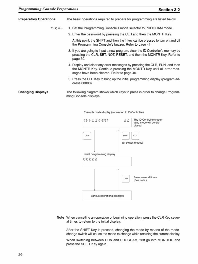
The following diagram shows which keys to press in order to change Program-ming Console displays.
Example mode display (connected to ID Controller)
The ID Controller’s oper-ating mode will be dis-played.
Initial programming display
Press several times.(See note.)
(or switch modes)
Various operational displays
CLR SHIFT CLR
CLR
Note When cancelling an operation or beginning operation, press the CLR Key sever-al times to return to the initial display.
After the SHIFT Key is pressed, changing the mode by means of the mode-change switch will cause the mode to change while retaining the current display.
When switching between RUN and PROGRAM, first go into MONITOR andpress the SHIFT Key again.
Preparatory Operations
Changing Displays
Programming Console Preparations Section 3-2
!
37
3-3 Programming Console Operations
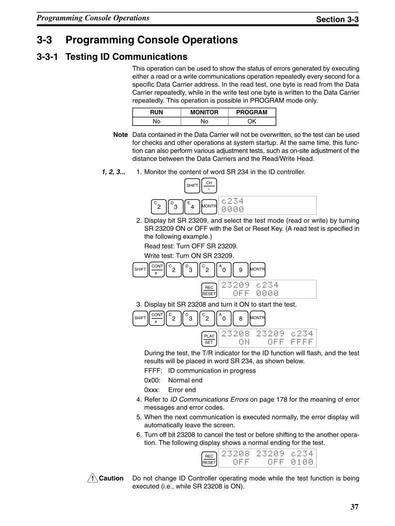
3-3-1 Testing ID CommunicationsThis operation can be used to show the status of errors generated by executingeither a read or a write communications operation repeatedly every second for aspecific Data Carrier address. In the read test, one byte is read from the DataCarrier repeatedly, while in the write test one byte is written to the Data Carrierrepeatedly. This operation is possible in PROGRAM mode only.
RUN MONITOR PROGRAM
No No OK
Note Data contained in the Data Carrier will not be overwritten, so the test can be usedfor checks and other operations at system startup. At the same time, this func-tion can also perform various adjustment tests, such as on-site adjustment of thedistance between the Data Carriers and the Read/Write Head.
1, 2, 3... 1. Monitor the content of word SR 234 in the ID controller.
SHIFTCH
*
C2
D3
E4 MONTR
2. Display bit SR 23209, and select the test mode (read or write) by turningSR 23209 ON or OFF with the Set or Reset Key. (A read test is specified inthe following example.)
Read test: Turn OFF SR 23209.
Write test: Turn ON SR 23209.
SHIFTCONT
#
C2
D3
C2
A0 9 MONTR
REC
RESET
3. Display bit SR 23208 and turn it ON to start the test.
SHIFTCONT
#
C2
D3
C2
A0 8 MONTR
PLAY
SET
During the test, the T/R indicator for the ID function will flash, and the testresults will be placed in word SR 234, as shown below.
FFFF: ID communication in progress
0x00: Normal end
0xxx: Error end
4. Refer to ID Communications Errors on page 178 for the meaning of errormessages and error codes.
5. When the next communication is executed normally, the error display willautomatically leave the screen.
6. Turn off bit 23208 to cancel the test or before shifting to the another opera-tion. The following display shows a normal ending for the test.
REC
RESET
Caution Do not change ID Controller operating mode while the test function is beingexecuted (i.e., while SR 23208 is ON).
Programming Console Operations Section 3-3

38
3-3-2 Reading the ID Error Log When the ID Controller is running in the operating mode, information on varioustypes of errors is stored in the DM area in the ID Error Log and in the ID ErrorStatistics Log. This information can be displayed on the Programming Consoleas error messages.
ID Error Log The last 30 errors are displayed in order of the error log data number.
ID Error Statistics Log The numbers of ID communications errors generated are displayed by the typeof error.
Note The ID Error Log and ID Error Statistics Log may or may not be stored in memorydepending on ID Controller Setup. ID error log information is stored in one of twoways, leaving either the newest error or the first 30 errors. Refer to 5-1 ID Con-troller Setup for details.
Displaying ID Error Log Records1, 2, 3... 1. Press the Shift Key and the Monitor Key to display ID error menu.
SHIFT MONTR!"
#$#
2. Press the 1 Key to display the ID communications error log.
B1
$% # #
The different portions of the display are given in the following table, using thedata in the above example display.
Displayed data Meaning
05 The date that the error was generated.
10:14:20 The time that an error was generated. If the MemoryCassette used is not equipped with a clock function, thedate and time will be displayed as all zeros.
NO1 The error log data number. Here, N30 is the most recent,and N01 is the oldest error.
RD The command that generated the error. In this case, it isIDRD. The following displays will appear for IDcommunications instructions:RD: IDRD
AR: IDAR
WT: IDWT
AW: IDAW
MD: IDMD
CA: IDCA
COM.DC E The error message. Refer to 1-1-3 ID Controller Functionsfor the meaning of error messages.
3. Press the Down Cursor Key shifts the display from the current position to thenext most recent error.
↓$ %# #
!
Pressing the Up Cursor Key shifts the display from the current position to theoldest error.
Pressing the Up Cursor Key with N01 data displayed, displays N30 data,and pressing the Down Cursor Key with N30 data displayed, displays N01data.
4. Press the Clear Key to leave the ID error log display, and returns to the initialdisplay.
The following display will appear when there are no ID error logs.
$
Programming Console Operations Section 3-3

!
39
The following display will appear while reading the ID communications error logand the display has been moved past the last recorded error.
$##
ID errors are displayed by pressing the shift key and the monitor key in that order.
Displaying ID Error Statistics Log
1, 2, 3... 1. Press the Shift Key and the Monitor Key to display ID error menu.
SHIFT MONTR!"
#$#
2. Press the 2 Key to display the ID error statistics log.
C2
The different portions of the display are given in the following table, using thedata in the above example display.
Displayed data Meaning
0004 The number of times the specified type of error hasoccurred.
COM.DC E The error message. Refer to 1-1-3 ID Controller Functionsfor the meaning of error messages.
3. Press the Down Cursor Key to display the number of times an error was gen-erated for the next error code number.
↓
Pressing the Up Cursor Key displays the number of times an error was gen-erated for the previous error code number.
4. Press the Clear Key to quit the ID Error Statistics Log display and return tothe initial screen.
3-3-3 Clearing MemoryThis operation is used to clear all or part of the Program Memory and any dataareas that are not read-only. This operation is possible in PROGRAM mode only.
RUN MONITOR PROGRAM
No No OK
Caution The ID Controller Setup (DM 6600 through DM 6655) will be cleared along withthe rest of the DM area if the DM area is specified for clearing. The error log,however, will not be cleared.
The following procedure is used to clear memory completely.
1, 2, 3... 1. Bring up the initial display by pressing the CLR key repeatedly.
2. Press the SET, NOT, and then the RESET Key to begin the operation.
SET NOT RESET$&
!
3. Press the MONTR Key to clear memory completely.
MONTR$
!
All Clear
Programming Console Operations Section 3-3
40
It is possible to retain the data in specified areas or part of the ProgramMemory. To retain the data in the HR, TC, or DM Areas, press the appropri-ate key after pressing SET, NOT, and RESET. Any data area that still ap-pears on the display will be cleared when the MONTR Key is pressed.
The HR Key is used to specify both the AR and HR Areas, the CNT Key isused to specify the entire timer/counter area, and the DM Key is used tospecify the DM Area.
It is also possible to retain a portion of the Program Memory from the firstmemory address to a specified address. After designating the data areas tobe retained, specify the first Program Memory address to be cleared. For ex-ample, input 030 to leave addresses 000 to 029 untouched, but to clear ad-dresses from 030 to the end of Program Memory.
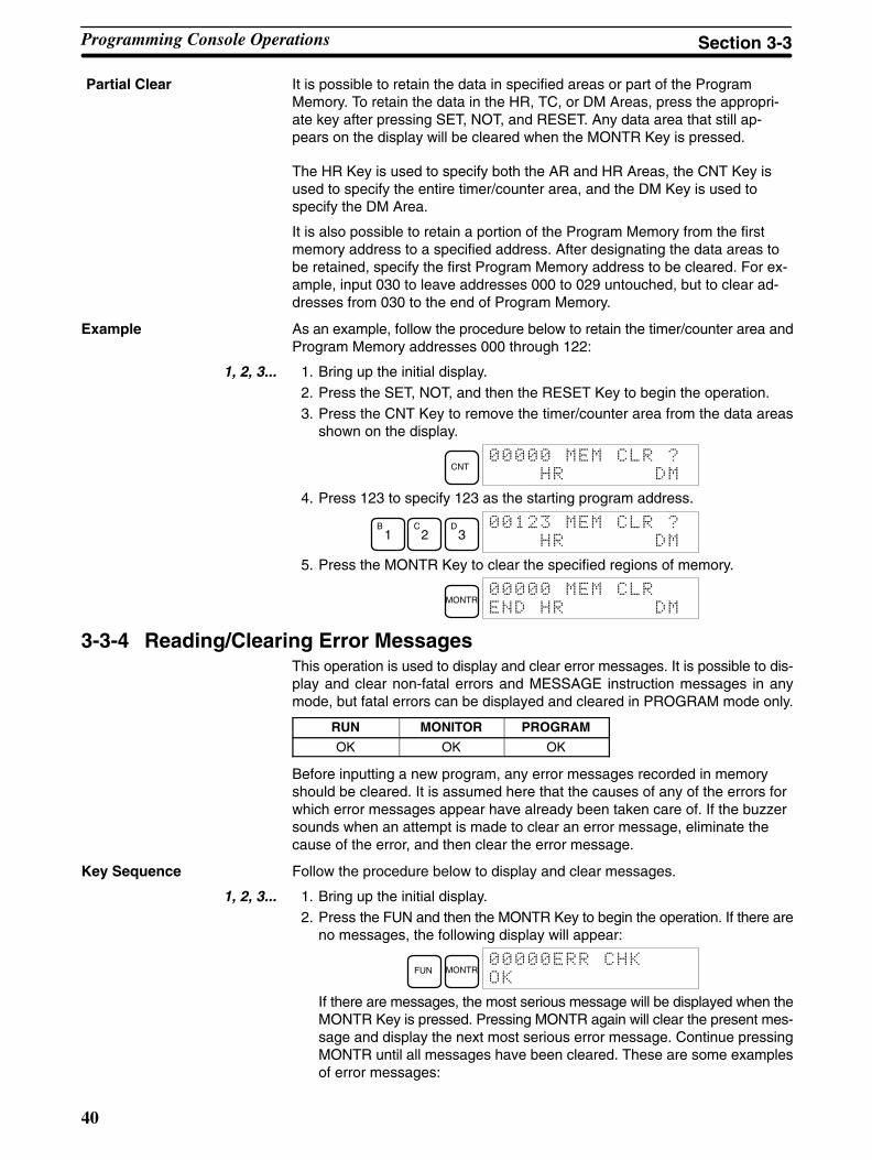
Example As an example, follow the procedure below to retain the timer/counter area andProgram Memory addresses 000 through 122:
1, 2, 3... 1. Bring up the initial display.2. Press the SET, NOT, and then the RESET Key to begin the operation.3. Press the CNT Key to remove the timer/counter area from the data areas
shown on the display.
CNT$&
!
4. Press 123 to specify 123 as the starting program address.
B1
C2
D3
$&
!
5. Press the MONTR Key to clear the specified regions of memory.
MONTR$
!
3-3-4 Reading/Clearing Error MessagesThis operation is used to display and clear error messages. It is possible to dis-play and clear non-fatal errors and MESSAGE instruction messages in anymode, but fatal errors can be displayed and cleared in PROGRAM mode only.
RUN MONITOR PROGRAM
OK OK OK
Before inputting a new program, any error messages recorded in memoryshould be cleared. It is assumed here that the causes of any of the errors forwhich error messages appear have already been taken care of. If the buzzersounds when an attempt is made to clear an error message, eliminate thecause of the error, and then clear the error message.
Key Sequence Follow the procedure below to display and clear messages.
1, 2, 3... 1. Bring up the initial display.2. Press the FUN and then the MONTR Key to begin the operation. If there are
no messages, the following display will appear:
FUN MONTR!"
"
If there are messages, the most serious message will be displayed when theMONTR Key is pressed. Pressing MONTR again will clear the present mes-sage and display the next most serious error message. Continue pressingMONTR until all messages have been cleared. These are some examplesof error messages:
Partial Clear
Programming Console Operations Section 3-3
!
41
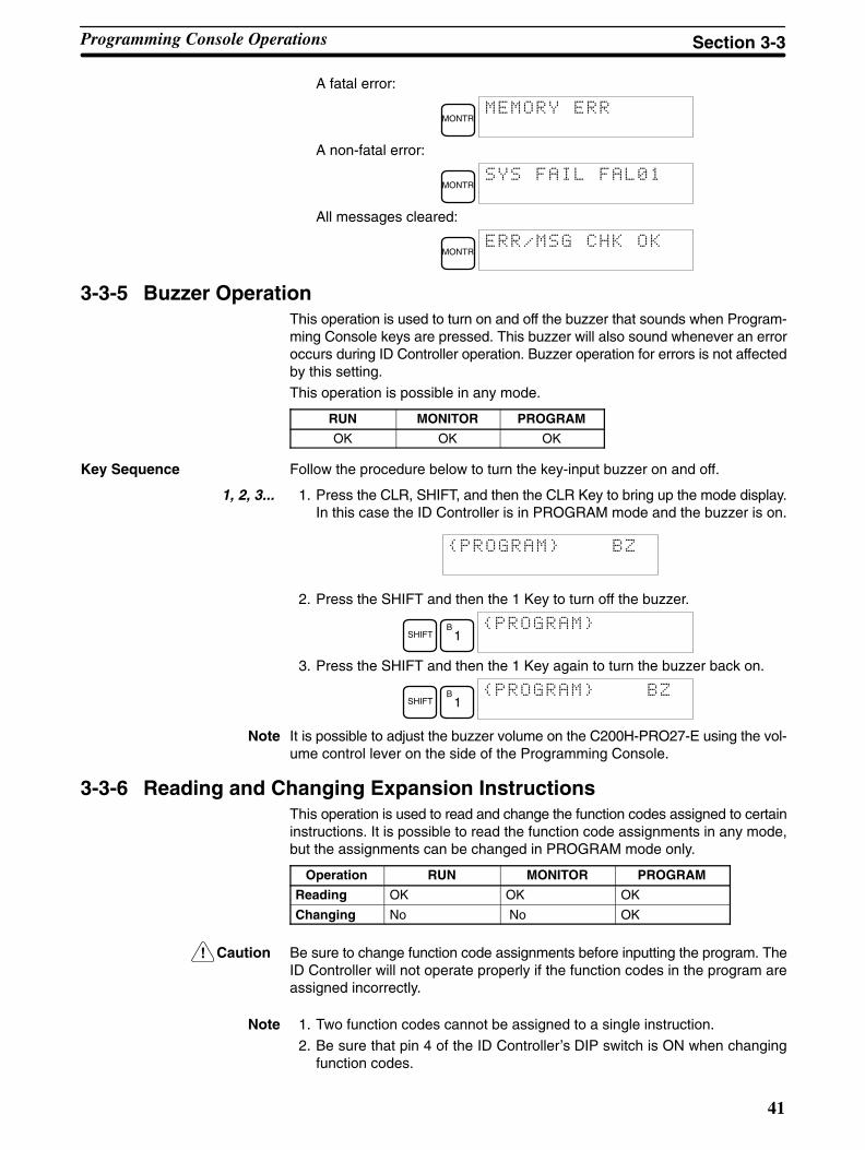
A fatal error:
MONTR
A non-fatal error:
MONTR$$
All messages cleared:
MONTR!""
3-3-5 Buzzer OperationThis operation is used to turn on and off the buzzer that sounds when Program-ming Console keys are pressed. This buzzer will also sound whenever an erroroccurs during ID Controller operation. Buzzer operation for errors is not affectedby this setting.
This operation is possible in any mode.
RUN MONITOR PROGRAM
OK OK OK
Key Sequence Follow the procedure below to turn the key-input buzzer on and off.
1, 2, 3... 1. Press the CLR, SHIFT, and then the CLR Key to bring up the mode display.In this case the ID Controller is in PROGRAM mode and the buzzer is on.
2. Press the SHIFT and then the 1 Key to turn off the buzzer.
SHIFTB
1
3. Press the SHIFT and then the 1 Key again to turn the buzzer back on.
SHIFTB
1
Note It is possible to adjust the buzzer volume on the C200H-PRO27-E using the vol-ume control lever on the side of the Programming Console.
3-3-6 Reading and Changing Expansion InstructionsThis operation is used to read and change the function codes assigned to certaininstructions. It is possible to read the function code assignments in any mode,but the assignments can be changed in PROGRAM mode only.
Operation RUN MONITOR PROGRAM
Reading OK OK OK
Changing No No OK
Caution Be sure to change function code assignments before inputting the program. TheID Controller will not operate properly if the function codes in the program areassigned incorrectly.
Note 1. Two function codes cannot be assigned to a single instruction.
2. Be sure that pin 4 of the ID Controller’s DIP switch is ON when changingfunction codes.
Programming Console Operations Section 3-3

42
Reading Function Codes Follow the procedure below to read out function code assignments.
1, 2, 3... 1. Bring up the initial display.2. Press the EXT Key.
EXT $
' (#
3. Use the Up and Down Cursor Keys to scroll through the function codes andread their corresponding instructions.
↓ ↑' #"
$
Changing Function Codes Follow the procedure below to change function code assignments. The assign-ments can be changed in PROGRAM mode only.
1, 2, 3... 1. Follow the procedure above to read out the function code which will bechanged.
2. Press the CHG Key. The following display will appear.
CHG' #"→&&&& $!&
3. Use the Up and Down Cursor Keys to scroll through the available instruc-tions.
↓' #"→!" $!&
4. When the desired instruction is displayed, press the WRITE Key to changethe function code assignment. The following display will appear if the se-lected instruction has not been assigned to another function code.
WRITE $
' #!"
Note It is not possible to change to an instruction which is already assignedto a different function code.
3-3-7 Reading and Changing the ClockThis operation is used to read and change the clock in ID Controllers that have aMemory Cassette equipped with a clock. It is possible to read the clock in anymode, but the clock can be changed in MONITOR or PROGRAM mode only.
Operation RUN MONITOR PROGRAM
Reading OK OK OK
Changing No OK OK
Reading the Clock Follow the procedure below to read the clock.
1, 2, 3... 1. Bring up the initial display.2. Press the FUN, SHIFT, and then the MONTR Key. The current clock setting
will be displayed.
FUN SHIFT MONTR)) (
#%*#*'+,
Changing the Clock Follow the procedure below to change the clock setting. The clock setting cannotbe changed in RUN mode.
1, 2, 3... 1. Follow the procedure above to display the current clock setting.2. Press the CHG Key. The following display will appear.
CHG!&-)) (
#%(#'+,
Programming Console Operations Section 3-3

43
3. Use the Up and Down Cursor Keys to move the cursor to the unit that will bechanged. In this case, the day of the week is being changed.
↓ ↑!&)) (
#%#'+-,
4. Input the new value and press the WRITE Key. The new setting will appearon the display.
D3 WRITE
)) (
#%#+,
Note The days of the week correspond to the following numbers: Sun.=0,Mon.=1, Tue.=2, Wed.=3, Thu.=4, Fri.=5, and Sat.=6.
3-3-8 Setting and Reading a Program Memory AddressThis operation is used to display the specified program memory address and ispossible in any mode.
RUN MONITOR PROGRAM
OK OK OK
When inputting a program for the first time, it is generally written to ProgramMemory starting from address 00000. Because this address appears whenthe display is cleared, it is not necessary to specify it.
When inputting a program starting from other than 00000 or to read or modifya program that already exists in memory, the desired address must be desig-nated.
1, 2, 3... 1. Bring up the initial display.
2. Input the desired address. It is not necessary to input leading zeroes.
C2
A0
A0
3. Press the Down Cursor Key.
↓
$
Note The ON/OFF status of any displayed bit will be shown if the ID Con-troller is in RUN or MONITOR mode.
4. Press the Up and Down Cursor Keys to scroll through the program.
↓
↑
$
Programming Console Operations Section 3-3

44
3-3-9 Inserting and Deleting InstructionsThis operation is used to insert or delete instructions from the program. It is pos-sible in PROGRAM mode only.
RUN MONITOR PROGRAM
No No OK
To demonstrate this operation, an IR 00105 NO condition will be inserted atprogram address 00206 and an IR 00103 NO condition deleted from address00205, as shown in the following diagram.
0010400100 00103
00105
00101
00201
END(01)
00102
10000
Delete
Insert
Original Program
Address Instruction Operands
00205 AND 00103
00206 AND NOT 00104
00207 OUT 10000
00208 END(01) -
DeleteInsert
Insertion Follow the procedure below to insert the IR 00105 NO condition at address00206.
1, 2, 3... 1. Bring up the initial display.2. Input the address where the NO condition will be inserted and press the
Down Cursor Key. It is not necessary to input leading zeroes.
C2
A0 6 ↓
*
3. Input the new instruction and press the INS Key.
AND B1
A0
F5 INS
* &
%
4. Press the Down Cursor Key to insert the new instruction.
Note For instructions that require more operands, input the operands andthen press the WRITE Key.
↓(
Deletion Follow the procedure below to delete the IR 00103 NO condition at address00205.
1, 2, 3... 1. Bring up the initial display.2. Input the address where the NO condition will be deleted and press the
Down Cursor Key. It is not necessary to input leading zeroes.
C2
A0
F5 ↓
%
3. Press the DEL Key.
DEL%$&
4. Press the Up Cursor Key to delete the specified instruction.If the instruction has more operands, the operands will be deleted automati-cally with the instruction.
↑%$
%
Programming Console Operations Section 3-3

45
After completing the insertion and deletion procedures, use the Up and DownCursor Keys to scroll through the program and verify that it has beenchanged correctly, as shown in the following diagram.
0010400100 0010500101
00201
END(01)
00102
10000
Corrected Program
Address Instruction Operands
00205 AND 00105
00206 AND NOT 00104
00207 OUT 10000
00208 END(01) -
3-3-10 Entering or Editing ProgramsThis operation is used enter or edit programs. It is possible in PROGRAM modeonly.
RUN MONITOR PROGRAM
No No OK
The same procedure is used to either input a program for the first time or tochange a program that already exists. In either case, the current contents ofProgram Memory is overwritten.
The program shown in the following diagram will be entered to demonstratethis operation.
00002
00200 LD IR 00002
00201 TIM 000
0123
00202 MOV(21)
#0100
LR 10
00203 ADB(50)
#0100
#FFF6
DM 0000
MOV(21)
#0100
LR 10
TIM 000
#0123 12.3 s
ADB(50)
#0100
#FFF6
DM 0000
Address Instruction Operands
1, 2, 3... 1. Bring up the initial display.2. Input the address where the program will begin.
C2
A0
A0
3. Input the first instruction and operand.
LD C2
$
4. Press the WRITE Key to write the instruction to Program Memory. The nextprogram address will be displayed.
WRITE
+,
If a mistake was made inputting the instruction, press the Up Cursor Key toreturn to the previous program address and input the instruction again. Themistaken instruction will be overwritten.
Programming Console Operations Section 3-3

46
5. Input the second instruction and operand. (In this case it isn’t necessary toenter the timer number, because it’s 000.) Press the WRITE Key to write theinstruction to Program Memory.
TIM Timer number WRITE
.
6. Input the SV as the second operand (123 to specify 12.3 seconds) and pressthe WRITE Key. The next program address will be displayed.
B1
C2
D3 WRITE
+,
If a mistake was made inputting the operand, press the Up Cursor Key toreturn to display the mistaken operand, press the CONT/# Key and 123again. The mistaken operand will be overwritten.
Note Counters are input in the same basic way as timers except the CNTKey is pressed instead of the TIM Key.
7. Input the third instruction and its operands. First input the instruction bypressing the FUN Key and then the function code (21 in this case).
FUNC
2B
1
+ ,
Note To input a differentiated instruction, press the NOT Key after enteringthe function code. The “@” symbol will be displayed next to differen-tiated instructions. Press the NOT Key again to change back theinstruction back to a non-differentiated instruction. The “@” symbolwill disappear. To change an instruction after it has been entered,simply scroll through the program until the desired instruction is dis-played and press the NOT Key. The “@” symbol should be displayednext to the instruction.
8. Press the WRITE Key to write the instruction to Program Memory. The inputdisplay for the first operand will be displayed.
WRITE
• Writing Hexadecimal, BCD Constants
9. Input the first operand and press the WRITE Key to write the instruction toProgram Memory. The input display for the second operand will appear.
CONT
#
B1
A0
A0 WRITE
.
• Writing Word Addresses
10. Input the second operand and press the WRITE Key to write the instructionto Program Memory. The next program address will be displayed.
LRB
1A
0 WRITE
+,
Note When an instruction operand is input, the designation the operand asa bit or word can be abbreviated.
11. Write the application instruction.
FUNF
5A
0 WRITE
.
Programming Console Operations Section 3-3

47
3-3-11 Checking the ProgramOnce a program has been entered or edited, its syntax should be checked tobe sure that no programming rules have been violated.
This operation checks for programming errors and displays the program ad-dress and error when errors are found. It is possible in PROGRAM modeonly.
RUN MONITOR PROGRAM
No No OK
1, 2, 3... 1. Bring up the initial display.
2. Press the SRCH Key. An input prompt will appear requesting the desiredcheck level.
SRCH!"
!"$$+),&
3. Input the desired check level (0, 1, or 2). The program check will begin whenthe check level is input, and the first error found will be displayed.
A0
('
'
Note Refer to 9-3 Programming Errors for details on check levels.
4. Press the SRCH Key to continue the search. The next error will be dis-played. Continue pressing the SRCH Key to continue the search.
The search will continue until an END(01) instruction or the end of ProgramMemory is reached. A display like this will appear if the end of ProgramMemory is reached and END(01) is not found:
SRCH
A display like this will appear if an END instruction is reached:
!"
+ ,+",
Note The search can be cancelled at any time by pressing the CLR Key.
3-3-12 Bit, Digit, Word MonitorThis operation is used to monitor the status of up to 16 bits and words, al-though only 3 can be shown on the display at any one time. Operation is pos-sible in any mode.
RUN MONITOR PROGRAM
OK OK OK
Program Read then Monitor When a program address is being displayed, the status of the bit or word in thataddress can be monitored by pressing the MONTR Key.
1, 2, 3... 1. Bring up the initial display.
2. Input the desired program address and press the Down Cursor Key.
B1
A0
A0 ↓
3. Press the MONTR Key to begin monitoring.
MONTR
Programming Console Operations Section 3-3
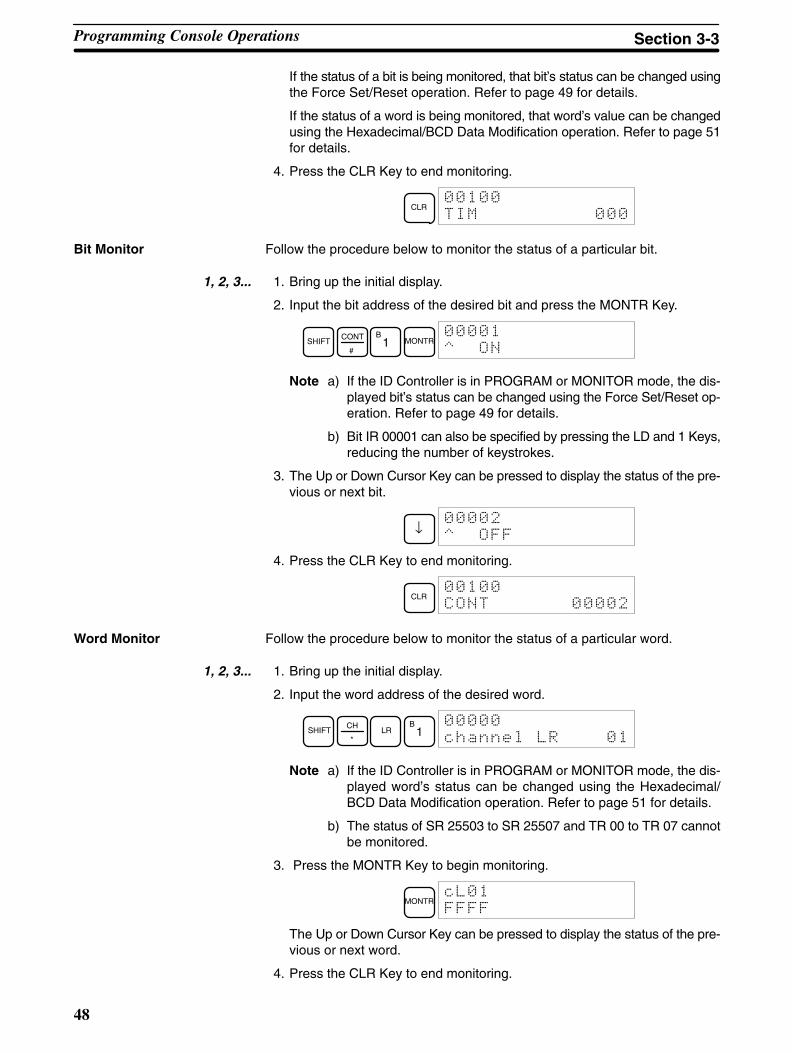
48
If the status of a bit is being monitored, that bit’s status can be changed usingthe Force Set/Reset operation. Refer to page 49 for details.
If the status of a word is being monitored, that word’s value can be changedusing the Hexadecimal/BCD Data Modification operation. Refer to page 51for details.
4. Press the CLR Key to end monitoring.
CLR
Bit Monitor Follow the procedure below to monitor the status of a particular bit.
1, 2, 3... 1. Bring up the initial display.
2. Input the bit address of the desired bit and press the MONTR Key.
SHIFTCONT
#
B1 MONTR
/
Note a) If the ID Controller is in PROGRAM or MONITOR mode, the dis-played bit’s status can be changed using the Force Set/Reset op-eration. Refer to page 49 for details.
b) Bit IR 00001 can also be specified by pressing the LD and 1 Keys,reducing the number of keystrokes.
3. The Up or Down Cursor Key can be pressed to display the status of the pre-vious or next bit.
↓
/
4. Press the CLR Key to end monitoring.
CLR
Word Monitor Follow the procedure below to monitor the status of a particular word.
1, 2, 3... 1. Bring up the initial display.
2. Input the word address of the desired word.
SHIFTCH
*LR
B1
012234$
Note a) If the ID Controller is in PROGRAM or MONITOR mode, the dis-played word’s status can be changed using the Hexadecimal/BCD Data Modification operation. Refer to page 51 for details.
b) The status of SR 25503 to SR 25507 and TR 00 to TR 07 cannotbe monitored.
3. Press the MONTR Key to begin monitoring.
MONTR$
The Up or Down Cursor Key can be pressed to display the status of the pre-vious or next word.
4. Press the CLR Key to end monitoring.
Programming Console Operations Section 3-3

49
3-3-13 Hex-ASCII Display ChangeThis operation is used to convert word data displays back and forth between4-digit hexadecimal data and ASCII. It is possible in any mode.
RUN MONITOR PROGRAM
OK OK OK
1, 2, 3... 1. Monitor the status of the desired word according to the procedure describedin 3-3-12 Bit, Digit, Word Monitor. If two or more words are being monitored,the desired word should be leftmost on the display.
2. Press the TR Key to switch to ASCII display. The display will toggle betweenhexadecimal and ASCII displays each time the TR Key is pressed.
TR
55
TR
3-3-14 Displaying the Cycle TimeThis operation is used to display the current average cycle time (scan time).It is possible only in RUN or MONITOR mode while the program is being exe-cuted.
RUN MONITOR PROGRAM
OK OK No
1, 2, 3... 1. Bring up the initial display.2. Press the MONTR Key to display the cycle time.
MONTR
There might be differences in displayed values when the MONTR Key ispressed repeatedly. These differences are caused by changing executionconditions.
3-3-15 Force Set, ResetThis operation is used to force bits ON (force set) or OFF (force reset) and isuseful when debugging the program or checking output wiring. It is possiblein MONITOR or PROGRAM mode only.
RUN MONITOR PROGRAM
No OK OK
1, 2, 3... 1. Monitor the status of the desired bit according to the procedure described in3-3-12 Bit, Digit, Word Monitor. If two or more words are being monitored,the desired bit should be leftmost on the display.
2. Press the SET Key to force the bit ON or press the RESET Key to turn the bitOFF.
SET %
/
The cursor in the lower left corner of the display indicates that the force set/reset is in progress. Bit status will remain ON or OFF only as long as the keyis held down; the original status will return one cycle after the key is re-leased.If a timer or counter is force reset in MONITOR mode, it will begin operationagain after completion if its input is on and will stop when the time is up.
Programming Console Operations Section 3-3

50
3. Press the SHIFT+SET or SHIFT+RESET Keys to maintain the status of thebit after the key is released. In this case, the force-set status is indicated byan “S” and the force-reset status is indicated by an “R.”To return the bit to its original status, press the NOT key or perform the ClearForce Set/Reset operation. (Refer to 3-3-16 Clear Force Set/Reset for de-tails.) Forced status will also be cleared when the ID Controller’s operatingmode is changed (unless SR 25211 is ON, in which case forced status willnot be cleared when changing from PROGRAM to MONITOR mode) orwhen operation stops as the result of an error or power interruption.
3-3-16 Clear Force Set/ResetThis operation is used to restore the status of all bits which have been forceset or reset. It is possible in MONITOR or PROGRAM mode only.
RUN MONITOR PROGRAM
No OK OK
1, 2, 3... 1. Bring up the initial display.2. Press the SET and then the RESET Key. A confirmation message will ap-
pear.
SET RESET$&
Note If you mistakenly press the wrong key, press CLR and start againfrom the beginning.
3. Press the NOT Key to clear the force-set/reset status of bits in all data areas.
NOT$
Note Forced status will also be cleared when the ID Controller’s operating mode ischanged (unless SR 25211 is ON, in which case forced status will not be clearedwhen changing from PROGRAM to MONITOR mode) or when operation stopsas the result of an error or power interruption.
3-3-17 Binary MonitorThis operation is used to monitor the ON/OFF status of any word’s 16 bits. Itis possible in any mode.
RUN MONITOR PROGRAM
OK OK OK
1, 2, 3... 1. Monitor the status of the desired word according to the procedure describedin 3-3-12 Bit, Digit, Word Monitor. The desired word should be leftmost onthe display if 2 or more words are being monitored.
2. Press the SHIFT and then the MONTR Key to begin binary monitoring. TheON/OFF status of the selected word’s 16 bits will be shown along the bottomof the display. A 1 indicates a bit is on, and a 0 indicates it is off.
SHIFT MONTR
The status of force-set bits is indicated by “S,” and the status of a force-resetbits is indicated by “R,” as shown below.
Force-set bit
Force-reset bit
Programming Console Operations Section 3-3

51
Note a) The status of displayed bits can be changed at this point. Refer to3-3-19 Binary Data Modification for details.
b) The Up or Down Cursor Key can be pressed to display the statusof the previous or next word’s bits.
3. Press the CLR Key to end binary monitoring and return to the normal moni-toring display.Press the SHIFT+CLR Keys to end monitoring altogether.
3-3-18 Hexadecimal, BCD Data ModificationThis operation is used to change the BCD or hexadecimal value of a wordbeing monitored using the procedure described in 3-3-12 Bit, Digit, WordMonitor. It is possible in MONITOR or PROGRAM mode only.
RUN MONITOR PROGRAM
No OK OK
Words SR 253 to SR 255 cannot be changed.
1, 2, 3... 1. Monitor the status of the desired word according to the procedure describedin 3-3-12 Bit, Digit, Word Monitor. If two or more words are being monitored,the desired word should be leftmost on the display.
2. Press the CHG Key to begin hexadecimal, BCD data modification.
CHG$&
&&&&
If a timer or counter is leftmost on the display, its PV will be displayed and willbe the value changed.In MONITOR mode, the timer’s PV will be counting down if the timer is on.
3. Input the new PV and press the WRITE Key to change the PV. Be sure toinput timer or counter PVs in BCD only.The operation will end and the normal monitoring display will return whenthe WRITE Key is pressed.
C2
A0
A0 WRITE
The timer’s PV will continue counting down from the new PV if the timer ison.
3-3-19 Binary Data ModificationThis operation is used to change the status of a word’s bits when the word ismonitored using the procedure described in 3-3-17 Binary Monitor. It is pos-sible in MONITOR or PROGRAM mode only.
RUN MONITOR PROGRAM
No OK OK
Bits SR 25300 to SR 25507 cannot be changed.
1, 2, 3... 1. Monitor the status of the desired word according to the procedure described3-3-17 Binary Monitor.
2. Press the CHG Key to begin binary data modification.
CHG !&
A flashing cursor will appear over bit 15. The cursor indicates which bit canbe changed.
3. Three sets of keys are used to move the cursor and change bit status:a) Use the Up and Down Cursor Keys to move the cursor to the left and
right.
Programming Console Operations Section 3-3
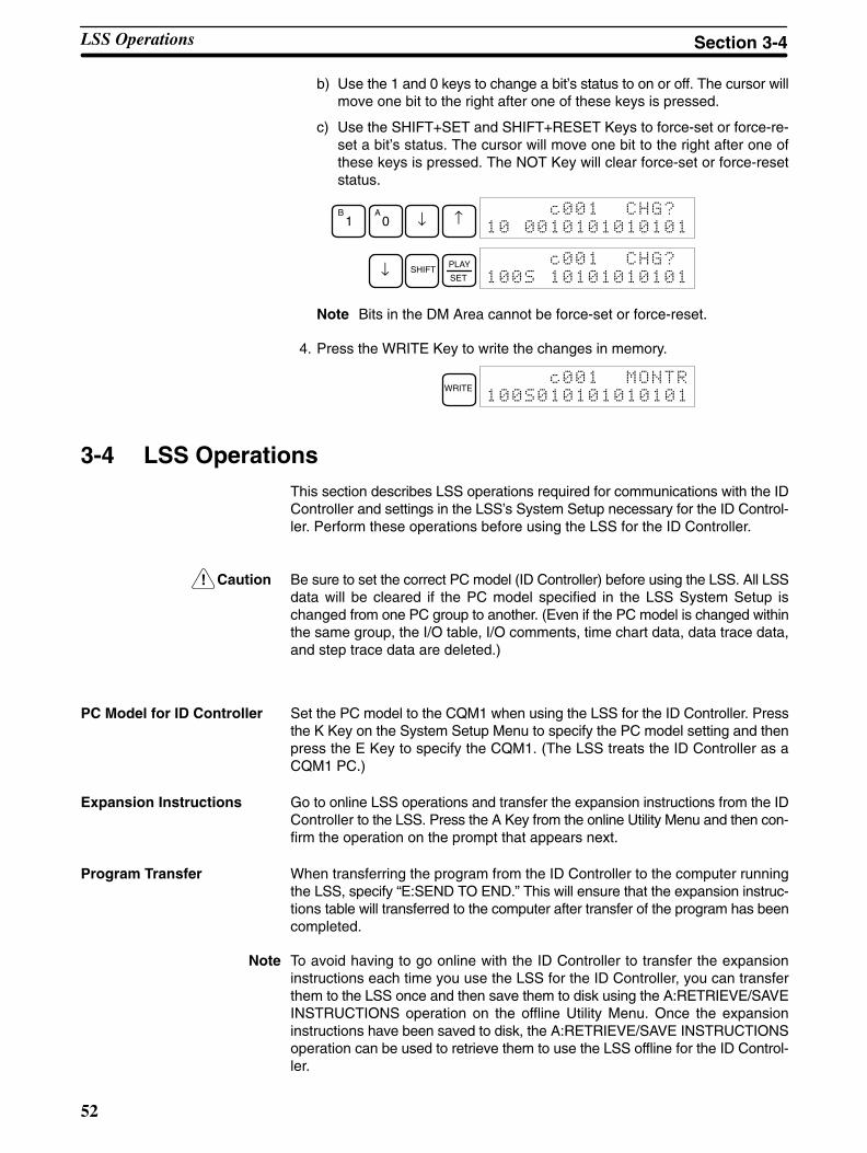
!
52
b) Use the 1 and 0 keys to change a bit’s status to on or off. The cursor willmove one bit to the right after one of these keys is pressed.
c) Use the SHIFT+SET and SHIFT+RESET Keys to force-set or force-re-set a bit’s status. The cursor will move one bit to the right after one ofthese keys is pressed. The NOT Key will clear force-set or force-resetstatus.
B1
A0 ↓ ↑
!&
↓ SHIFTPLAY
SET
!&
Note Bits in the DM Area cannot be force-set or force-reset.
4. Press the WRITE Key to write the changes in memory.
WRITE
3-4 LSS OperationsThis section describes LSS operations required for communications with the IDController and settings in the LSS’s System Setup necessary for the ID Control-ler. Perform these operations before using the LSS for the ID Controller.
Caution Be sure to set the correct PC model (ID Controller) before using the LSS. All LSSdata will be cleared if the PC model specified in the LSS System Setup ischanged from one PC group to another. (Even if the PC model is changed withinthe same group, the I/O table, I/O comments, time chart data, data trace data,and step trace data are deleted.)
PC Model for ID Controller Set the PC model to the CQM1 when using the LSS for the ID Controller. Pressthe K Key on the System Setup Menu to specify the PC model setting and thenpress the E Key to specify the CQM1. (The LSS treats the ID Controller as aCQM1 PC.)
Expansion Instructions Go to online LSS operations and transfer the expansion instructions from the IDController to the LSS. Press the A Key from the online Utility Menu and then con-firm the operation on the prompt that appears next.
Program Transfer When transferring the program from the ID Controller to the computer runningthe LSS, specify “E:SEND TO END.” This will ensure that the expansion instruc-tions table will transferred to the computer after transfer of the program has beencompleted.
Note To avoid having to go online with the ID Controller to transfer the expansioninstructions each time you use the LSS for the ID Controller, you can transferthem to the LSS once and then save them to disk using the A:RETRIEVE/SAVEINSTRUCTIONS operation on the offline Utility Menu. Once the expansioninstructions have been saved to disk, the A:RETRIEVE/SAVE INSTRUCTIONSoperation can be used to retrieve them to use the LSS offline for the ID Control-ler.
LSS Operations Section 3-4

!
53
3-5 SSS OperationsThis section describes SSS operations required for communications with the IDController and settings in the SSS’s System Setup necessary for the ID Control-ler. Perform these operations before using the SSS for the ID Controller.
Caution Be sure to set the correct PC model (ID Controller) before using the SSS. All SSSdata will be cleared if the PC model specified in the SSS System Setup ischanged from one PC group to another. (Even if the PC model is changed withinthe same group, the I/O comment, I/O table, time chart data, data trace data, andstep trace data are deleted.)
PC Model for ID Controller Set the PC model to the CQM1 when using the SSS for the ID Controller. Pressthe K Key on the System Setup Menu to specify the PC model setting and thenpress the H Key to specify the CQM1. (The SSS treats the ID Controller as aCQM1 PC.)
Expansion Instructions The expansion instructions for the ID Controller are already registered in theSSS. It is thus not necessary to transfer the expansion instructions when usingthe SSS; just be sure to transfer the instructions table.
Program Transfer When transferring the program from the ID Controller to the computer runningthe SSS, specify “E:SEND TO END.” This will ensure that the expansion instruc-tions table will transferred to the computer after transfer of the program has beencompleted.
SSS Operations Section 3-5

55
SECTION 4Data Areas
This section describes the structure and use of the data areas used by the ID Controller.
4-1 Data Area Structure 56. . . . . . . . . . . . . . . . . . . . . . . . . . . . . . . . . . . . . . . . . . . . . . . . . . . . . . . 4-2 Data Area Functions 57. . . . . . . . . . . . . . . . . . . . . . . . . . . . . . . . . . . . . . . . . . . . . . . . . . . . . . . 4-3 ID Controller Area 60. . . . . . . . . . . . . . . . . . . . . . . . . . . . . . . . . . . . . . . . . . . . . . . . . . . . . . . .
4-3-1 ID Flags Timing 61. . . . . . . . . . . . . . . . . . . . . . . . . . . . . . . . . . . . . . . . . . . . . . . . . . . 4-3-2 Autoread/Write Flags 61. . . . . . . . . . . . . . . . . . . . . . . . . . . . . . . . . . . . . . . . . . . . . . .
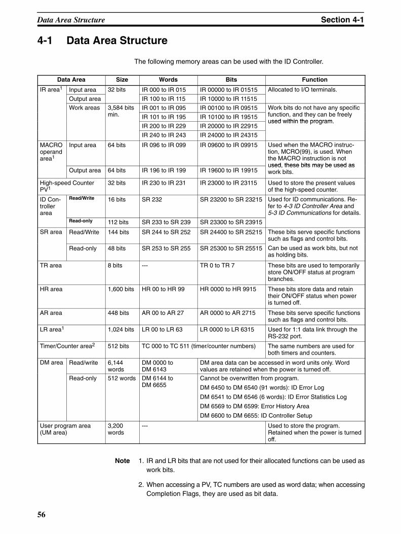
56
4-1 Data Area Structure
The following memory areas can be used with the ID Controller.
Data Area Size Words Bits Function
IR area1 Input area 32 bits IR 000 to IR 015 IR 00000 to IR 01515 Allocated to I/O terminals.
Output area IR 100 to IR 115 IR 10000 to IR 11515
Work areas 3,584 bitsi
IR 001 to IR 095 IR 00100 to IR 09515 Work bits do not have any specificf i d h b f l
,min. IR 101 to IR 195 IR 10100 to IR 19515
y pfunction, and they can be freelyused within the program
IR 200 to IR 229 IR 20000 to IR 22915used within the program.
IR 240 to IR 243 IR 24000 to IR 24315
MACROoperandarea1
Input area 64 bits IR 096 to IR 099 IR 09600 to IR 09915 Used when the MACRO instruc-tion, MCRO(99), is used. Whenthe MACRO instruction is notused these bits may be used as
Output area 64 bits IR 196 to IR 199 IR 19600 to IR 19915used, these bits may be used aswork bits.
High-speed CounterPV1
32 bits IR 230 to IR 231 IR 23000 to IR 23115 Used to store the present valuesof the high-speed counter.
ID Con-trollerarea
Read/Write 16 bits SR 232 SR 23200 to SR 23215 Used for ID communications. Re-fer to 4-3 ID Controller Area and5-3 ID Communications for details.
Read-only 112 bits SR 233 to SR 239 SR 23300 to SR 23915
SR area Read/Write 144 bits SR 244 to SR 252 SR 24400 to SR 25215 These bits serve specific functionssuch as flags and control bits.
Read-only 48 bits SR 253 to SR 255 SR 25300 to SR 25515
g
Can be used as work bits, but notas holding bits.
TR area 8 bits --- TR 0 to TR 7 These bits are used to temporarilystore ON/OFF status at programbranches.
HR area 1,600 bits HR 00 to HR 99 HR 0000 to HR 9915 These bits store data and retaintheir ON/OFF status when poweris turned off.
AR area 448 bits AR 00 to AR 27 AR 0000 to AR 2715 These bits serve specific functionssuch as flags and control bits.
LR area1 1,024 bits LR 00 to LR 63 LR 0000 to LR 6315 Used for 1:1 data link through theRS-232 port.
Timer/Counter area2 512 bits TC 000 to TC 511 (timer/counter numbers) The same numbers are used forboth timers and counters.
DM area Read/write 6,144words
DM 0000 toDM 6143
DM area data can be accessed in word units only. Wordvalues are retained when the power is turned off.
Read-only 512 words DM 6144 toDM 6655
Cannot be overwritten from program.
DM 6450 to DM 6540 (91 words): ID Error Log
DM 6541 to DM 6546 (6 words): ID Error Statistics Log
DM 6569 to DM 6599: Error History Area
DM 6600 to DM 6655: ID Controller Setup
User program area(UM area)
3,200words
--- Used to store the program.Retained when the power is turnedoff.
Note 1. IR and LR bits that are not used for their allocated functions can be used aswork bits.
2. When accessing a PV, TC numbers are used as word data; when accessingCompletion Flags, they are used as bit data.
Data Area Structure Section 4-1

57
4-2 Data Area Functions
The functions of the various data areas are explained below.
IR Area IR area bits are allocated to I/O terminals. They reflect the ON/OFF status of in-put and output signals. Input bits run from IR 00000 to IR 00015, and output bitsrun from IR 10000 to IR 10015.
Note Input bits cannot be used in output instructions. Do not use the same output bit inmore than one OUT and/or OUT NOT instruction, or the program will not executeproperly.
Work Bit Area Any of the bits between IR 001 and IR 229 and IR 240 to IR 243 not used forspecific functions can be used as work bits.
The work bits can be used freely within the program. They can only be used with-in the program, however, and not for direct external I/O. Work bits are reset (i.e.,turned OFF) when the ID Controller power supply is turned off or when operationbegins or stops.
The bits in the ranges shown below have specific functions, but can still be usedas work bits when their specific functions are not being used.
Range Function
IR 096 to IR 099 When the MACRO instruction is used, these bits serve as op-erand input bits.
IR 196 to IR 199 When the MACRO instruction is used, these bits serve as op-erand output bits.
IR 230 to IR 231 When high-speed counter is used, these bits are used to storeits present value.
LR 00 to LR 63 are used as link bits, but they can also be used as work bits whennot linked to another ID Controller. Refer to the CQM1 Programming Manual fordetails on using link bits in 1-to-1 communications.
SR Area These bits mainly serve as flags related to ID Controller operation. For details onthe various bit functions, refer to Appendix D AR and SR Area Allocations.
SR 244 to SR 247 can also be used as work bits, when input interrupts are notused in Counter Mode.
TR Area When a complex ladder diagram cannot be programmed in mnemonic code justas it is, these bits are used to temporarily store ON/OFF execution conditions atprogram branches. They are used only for mnemonic code. When programmingdirectly with ladder diagrams using the Ladder Support Software (LSS) or SYS-MAC Support Software (SSS), TR bits are automatically processed for you.
The same TR bits cannot be used more than once within the same instructionblock, but can be used again in different instruction blocks. The ON/OFF statusof TR bits cannot be monitored from a Peripheral Device.
HR Area These bits retain their ON/OFF status even after the ID Controller power supplyhas been turned off or when operation begins or stops. They are used in thesame way as work bits.
Data Area Functions Section 4-2
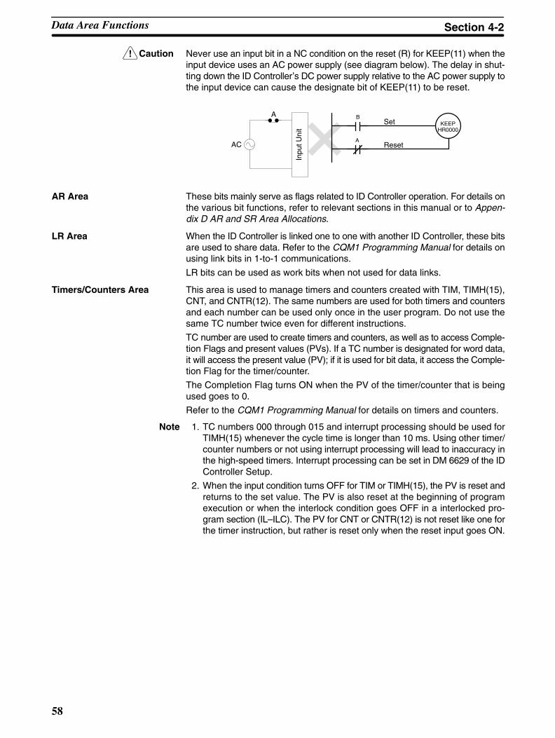
!
58
Caution Never use an input bit in a NC condition on the reset (R) for KEEP(11) when theinput device uses an AC power supply (see diagram below). The delay in shut-ting down the ID Controller’s DC power supply relative to the AC power supply tothe input device can cause the designate bit of KEEP(11) to be reset.
KEEPHR0000
B
AAC
Set
Reset
Inpu
t Uni
t
A
AR Area These bits mainly serve as flags related to ID Controller operation. For details onthe various bit functions, refer to relevant sections in this manual or to Appen-dix D AR and SR Area Allocations.
LR Area When the ID Controller is linked one to one with another ID Controller, these bitsare used to share data. Refer to the CQM1 Programming Manual for details onusing link bits in 1-to-1 communications.
LR bits can be used as work bits when not used for data links.
Timers/Counters Area This area is used to manage timers and counters created with TIM, TIMH(15),CNT, and CNTR(12). The same numbers are used for both timers and countersand each number can be used only once in the user program. Do not use thesame TC number twice even for different instructions.
TC number are used to create timers and counters, as well as to access Comple-tion Flags and present values (PVs). If a TC number is designated for word data,it will access the present value (PV); if it is used for bit data, it access the Comple-tion Flag for the timer/counter.
The Completion Flag turns ON when the PV of the timer/counter that is beingused goes to 0.
Refer to the CQM1 Programming Manual for details on timers and counters.
Note 1. TC numbers 000 through 015 and interrupt processing should be used forTIMH(15) whenever the cycle time is longer than 10 ms. Using other timer/counter numbers or not using interrupt processing will lead to inaccuracy inthe high-speed timers. Interrupt processing can be set in DM 6629 of the IDController Setup.
2. When the input condition turns OFF for TIM or TIMH(15), the PV is reset andreturns to the set value. The PV is also reset at the beginning of programexecution or when the interlock condition goes OFF in a interlocked pro-gram section (IL–ILC). The PV for CNT or CNTR(12) is not reset like one forthe timer instruction, but rather is reset only when the reset input goes ON.
Data Area Functions Section 4-2
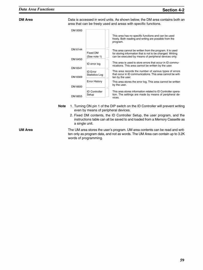
59
DM Area Data is accessed in word units. As shown below, the DM area contains both anarea that can be freely used and areas with specific functions.
DM 0000
DM 6144
DM 6450
DM 6541
DM 6569
Fixed DM
ID error log
ID Error Statistics Log
This area has no specific functions and can be usedfreely. Both reading and writing are possible from theprogram.
This area cannot be written from the program. It is usedfor storing information that is not to be changed. Writingcan be executed by means of peripheral devices only.
This area is used to store errors that occur in ID commu-nications. This area cannot be written by the user.
This area records the number of various types of errorsthat occur in ID communications. This area cannot be writ-ten by the user.
(See note 1)
DM 6600
Error History This area stores the error log. This area cannot be writtenby the user.
DM 6655
This area stores information related to ID Controller opera-tion. The settings are made by means of peripheral de-vices.
ID ControllerSetup
Note 1. Turning ON pin 1 of the DIP switch on the ID Controller will prevent writingeven by means of peripheral devices.
2. Fixed DM contents, the ID Controller Setup, the user program, and theinstructions table can all be saved to and loaded from a Memory Cassette asa single unit.
UM Area The UM area stores the user’s program. UM area contents can be read and writ-ten only as program data, and not as words. The UM Area can contain up to 3.2Kwords of programming.
Data Area Functions Section 4-2
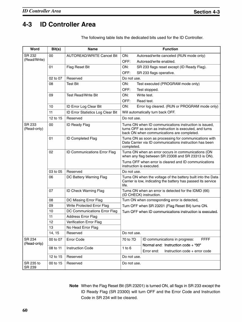
60
4-3 ID Controller Area
The following table lists the dedicated bits used for the ID Controller.
Word Bit(s) Name Function
SR 232 (Read/Write)
00 AUTOREAD/WRITE Cancel Bit ON: Autoread/write canceled (RUN mode only)
OFF: Autoread/write enabled.
01 Flag Reset Bit ON: SR 233 flags reset except (ID Ready Flag).
OFF: SR 233 flags operative.
02 to 07 Reserved Do not use.
08 Test Bit ON: Test executed (PROGRAM mode only)
OFF: Test stopped.
09 Test Read/Write Bit ON: Write test.
OFF: Read test.
10 ID Error Log Clear Bit ON: Error log cleared. (RUN or PROGRAM mode only)
11 ID Error Statistics Log Clear Bit
g ( y)
Will automatically turn back OFF.
12 to 15 Reserved Do not use.
SR 233 (Read-only)
00 ID Ready Flag Turns ON when ID communications instruction is issued,turns OFF as soon as instruction is executed, and turnsback ON when communications are completed.
01 ID Completed Flag Turns ON as soon as processing for communications withData Carrier via ID communications instruction has beencompleted.
02 ID Communications Error Flag Turns ON when an error occurs in communications (ONwhen any flag between SR 23308 and SR 23313 is ON).
Turns OFF when error is cleared and ID communicationsinstruction is executed.
03 to 05 Reserved Do not use.
06 DC Battery Warning Flag Turns ON when the voltage of the battery built into the DataCarrier is low, indicating the battery has passed its servicelife.
07 ID Check Warning Flag Turns ON when an error is detected for the IDMD (66)(ID CHECK) instruction.
08 DC Missing Error Flag Turn ON when corresponding error is detected,
09 Write Protected Error Flag
p g ,
Turn OFF when SR 23201 (Flag Reset Bit) turns ON.10 DC Communications Error Flag
Turn OFF when SR 23201 (Flag Reset Bit) turns ON.
Turn OFF when ID communications instruction is executed.11 Address Error Flag
Turn OFF when ID communications instruction is executed.
12 Verification Error Flag
13 No Head Error Flag
14, 15 Reserved Do not use.
SR 234 (Read-only)
00 to 07 Error Code 70 to 7D ID communications in progress: FFFF
Normal end: Instruction code + “00”(Read only)08 to 11 Instruction Code 1 to 6
Normal end: Instruction code + “00”
Error end: Instruction code + error code
12 to 15 Reserved Do not use.
SR 235 toSR 239
00 to 15 Reserved Do not use.
Note When the Flag Reset Bit (SR 23201) is turned ON, all flags in SR 233 except the
ID Ready Flag (SR 23300) will turn OFF and the Error Code and Instruction
Code in SR 234 will be cleared.
ID Controller Area Section 4-3

61
4-3-1 ID Flags TimingID Controller Bits in SR 232 are refreshed once each scan during overseeingprocessing. The setting for the refresh method in DM 6611, bits 03 to 07 does notaffect the refreshing of these flags
ID Controller Flags and Data in SR 233 and SR 234 are refreshed according tothe setting for the refresh method in DM 6611, bits 03 to 07 and can be set eitherfor cyclic or interrupt processing.
Cyclic processing refreshes memory only once each scan. Interrupt processingcauses an interrupt to be generated when ID communications have been com-pleted, refreshing SR 233 and SR 234 immediately after communications.
If the Error Flag (SR 25503) is not ON, the contents of SR 233 and SR 234 will beas shown below immediately after an ID communications instruction has beenissued, prevent other ID communications instructions from being executed.
SR 233: $0000SR 234: $FFFF
When ID communications have been completed, the ID Ready Flag (SR 23300)will turn ON, again enabling execution of ID communications instructions.
Note If the Flag Reset Bit (SR 23201) is ON when ID communications are completed,the content of SR 233 and SR 234 will be refreshed normally once, and then theircontent will be reset during the next overseeing processing stage.
The following timing chart illustrates the operation of the ID Controller Bits andFlags.
Programexecution
CPU processing
Scan time
ID Ready Flag(SR 23300)
Programexecution
Programexecution
Programexecution
ID CompletedFlag (SR 23301)
ID Comm ErrorFlag (SR 23302)
Error
No error
Warning Flags(SR 23306/07)
Error
No error
Error FlagsSR 23308 toSR 23315
Error
No error
ID communications instruction executed ID communications instruction executed
4-3-2 Autoread/Write FlagsThe ID Ready Flag (SR 23300) will turn OFF when the AUTOREAD (IDAR) orAUTOWRITE (IDAW) instruction is executed. If the Data Carrier cannot be de-tected within a specified period of time (i.e., if the ID Ready Flag does not comeON for a specified period of time), the Autoread/Write Cancel Bit (SR 23200) canbe turned ON to cancel the read/write instruction. The status of the ID ControllerFlags will be as follows after the instruction has been cancelled:
ID Ready Flag (SR 23300): ONOther Flags (SR 23301 to SR 23315): OFF
ID Controller Area Section 4-3

62
The Autoread/Write Cancel Bit (SR 23200) will not be effective, however, if it isturned ON after a Data Carrier has been detected. In this case, execution of theAUTOREAD (IDAR) or AUTOWRITE (IDAW) instruction will be continued nor-mally.
Note 1. Make sure that the ID Ready Flag (SR 23300) is OFF when you turn on theAutoread/Write Cancel Bit (SR 23200).
2. Data at the write destination for the AUTOREAD (IDAR) or AUTOWRITE(IDAW) instruction will not be changed if the instruction is cancelled.
ID Controller Area Section 4-3

63
SECTION 5ID Controller Functions and Setup
This section describes the functions of the ID Controller and the Setup that can be used to control those functions.
5-1 ID Controller Setup 64. . . . . . . . . . . . . . . . . . . . . . . . . . . . . . . . . . . . . . . . . . . . . . . . . . . . . . . 5-2 Basic Operations and I/O Processes 69. . . . . . . . . . . . . . . . . . . . . . . . . . . . . . . . . . . . . . . . . . . 5-3 ID Communications 73. . . . . . . . . . . . . . . . . . . . . . . . . . . . . . . . . . . . . . . . . . . . . . . . . . . . . . .
5-3-1 ID Communications Mode (DM 6611, Bits 00 to 03) 73. . . . . . . . . . . . . . . . . . . . . . 5-3-2 ID Communication Response Refresh Method (DM 6611, Bits 04 to 07) 73. . . . . . 5-3-3 Data Carrier Standby Time (DM 6643) 74. . . . . . . . . . . . . . . . . . . . . . . . . . . . . . . . . 5-3-4 Data Carrier Memory 75. . . . . . . . . . . . . . . . . . . . . . . . . . . . . . . . . . . . . . . . . . . . . . . 5-3-5 Data Carrier Life Detection Functions 77. . . . . . . . . . . . . . . . . . . . . . . . . . . . . . . . . 5-3-6 ID Communications Instructions 78. . . . . . . . . . . . . . . . . . . . . . . . . . . . . . . . . . . . . . 5-3-7 Reading Data Carriers –– IDRD(61)/IDAR(63) 79. . . . . . . . . . . . . . . . . . . . . . . . . . 5-3-8 Writing Data Carriers –– IDWT(62)/IDAW(64) 80. . . . . . . . . . . . . . . . . . . . . . . . . . 5-3-9 Cancelling DC AUTOREAD and DC AUTOWRITE 82. . . . . . . . . . . . . . . . . . . . . . 5-3-10 Clearing Data Carriers –– IDCA(65) 82. . . . . . . . . . . . . . . . . . . . . . . . . . . . . . . . . . . 5-3-11 Checking Data Carriers –– IDMD(66) 83. . . . . . . . . . . . . . . . . . . . . . . . . . . . . . . . . 5-3-12 Interrupt Refresh Program 85. . . . . . . . . . . . . . . . . . . . . . . . . . . . . . . . . . . . . . . . . . .
5-4 Advanced I/O Instructions 86. . . . . . . . . . . . . . . . . . . . . . . . . . . . . . . . . . . . . . . . . . . . . . . . . . 5-4-1 TEN-KEY INPUT – TKY(––) 86. . . . . . . . . . . . . . . . . . . . . . . . . . . . . . . . . . . . . . . 5-4-2 HEXADECIMAL KEY INPUT – HKY(––) 88. . . . . . . . . . . . . . . . . . . . . . . . . . . . . 5-4-3 DIGITAL SWITCH INPUT – DSW(––) 89. . . . . . . . . . . . . . . . . . . . . . . . . . . . . . . . 5-4-4 7-SEGMENT DISPLAY OUTPUT – 7SEG(––) 91. . . . . . . . . . . . . . . . . . . . . . . . . . 5-4-5 Alternate I/O Bits 93. . . . . . . . . . . . . . . . . . . . . . . . . . . . . . . . . . . . . . . . . . . . . . . . . .
5-5 Using Interrupts 94. . . . . . . . . . . . . . . . . . . . . . . . . . . . . . . . . . . . . . . . . . . . . . . . . . . . . . . . . . 5-5-1 Types of Interrupts 94. . . . . . . . . . . . . . . . . . . . . . . . . . . . . . . . . . . . . . . . . . . . . . . . . 5-5-2 ID Communications Response Interrupts 96. . . . . . . . . . . . . . . . . . . . . . . . . . . . . . . 5-5-3 Input Interrupts 96. . . . . . . . . . . . . . . . . . . . . . . . . . . . . . . . . . . . . . . . . . . . . . . . . . . 5-5-4 Masking All Interrupts 101. . . . . . . . . . . . . . . . . . . . . . . . . . . . . . . . . . . . . . . . . . . . . . 5-5-5 Interval Timer Interrupts 101. . . . . . . . . . . . . . . . . . . . . . . . . . . . . . . . . . . . . . . . . . . . 5-5-6 High-speed Counter Interrupts 104. . . . . . . . . . . . . . . . . . . . . . . . . . . . . . . . . . . . . . .
5-6 Communications 110. . . . . . . . . . . . . . . . . . . . . . . . . . . . . . . . . . . . . . . . . . . . . . . . . . . . . . . . . . 5-6-1 ID Controller Setup 111. . . . . . . . . . . . . . . . . . . . . . . . . . . . . . . . . . . . . . . . . . . . . . . . 5-6-2 Host Link and RS-232C Communications Parameters 111. . . . . . . . . . . . . . . . . . . . . 5-6-3 Host Link Communications 112. . . . . . . . . . . . . . . . . . . . . . . . . . . . . . . . . . . . . . . . . . 5-6-4 RS-232C Communications 114. . . . . . . . . . . . . . . . . . . . . . . . . . . . . . . . . . . . . . . . . . 5-6-5 One-to-one Link Communications 118. . . . . . . . . . . . . . . . . . . . . . . . . . . . . . . . . . . . 5-6-6 NT Link Communications 120. . . . . . . . . . . . . . . . . . . . . . . . . . . . . . . . . . . . . . . . . . .
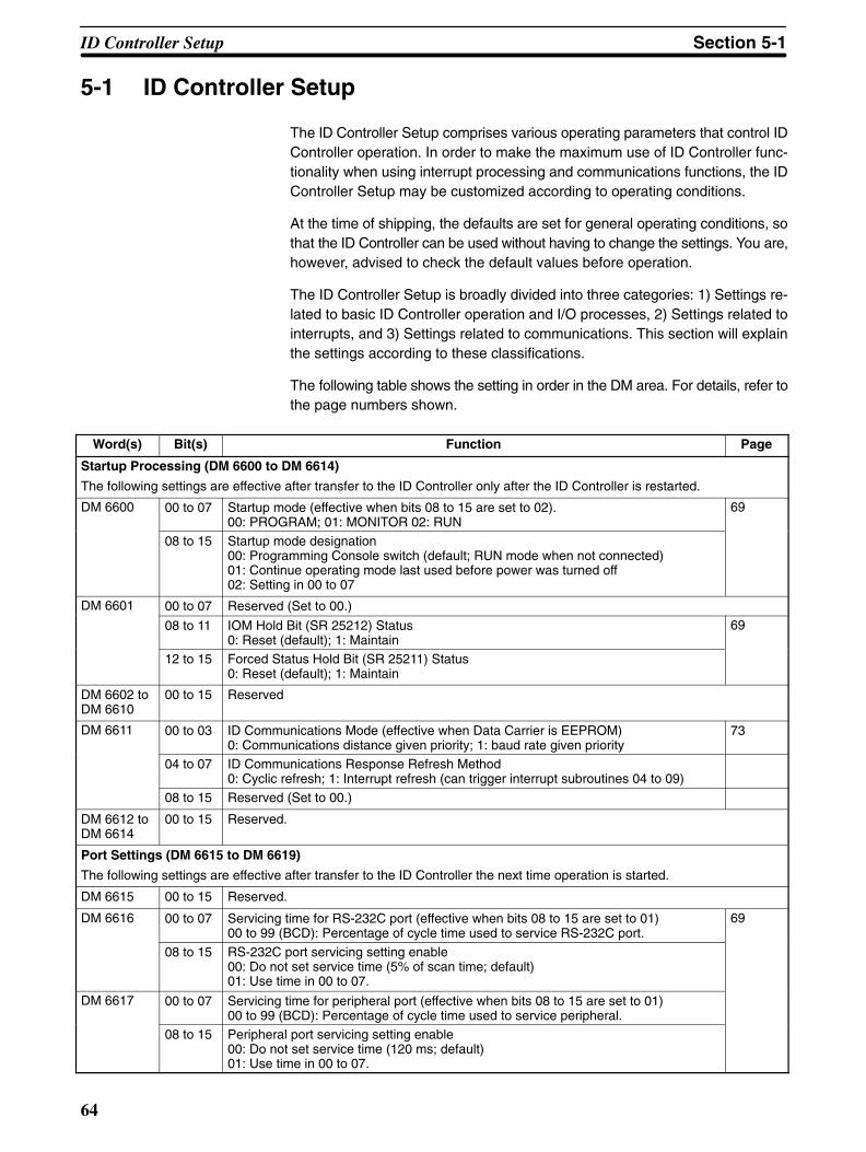
64
5-1 ID Controller Setup
The ID Controller Setup comprises various operating parameters that control IDController operation. In order to make the maximum use of ID Controller func-tionality when using interrupt processing and communications functions, the IDController Setup may be customized according to operating conditions.
At the time of shipping, the defaults are set for general operating conditions, sothat the ID Controller can be used without having to change the settings. You are,however, advised to check the default values before operation.
The ID Controller Setup is broadly divided into three categories: 1) Settings re-lated to basic ID Controller operation and I/O processes, 2) Settings related tointerrupts, and 3) Settings related to communications. This section will explainthe settings according to these classifications.
The following table shows the setting in order in the DM area. For details, refer tothe page numbers shown.
Word(s) Bit(s) Function Page
Startup Processing (DM 6600 to DM 6614)
The following settings are effective after transfer to the ID Controller only after the ID Controller is restarted.
DM 6600 00 to 07 Startup mode (effective when bits 08 to 15 are set to 02).00: PROGRAM; 01: MONITOR 02: RUN
69
08 to 15 Startup mode designation00: Programming Console switch (default; RUN mode when not connected)01: Continue operating mode last used before power was turned off02: Setting in 00 to 07
DM 6601 00 to 07 Reserved (Set to 00.)
08 to 11 IOM Hold Bit (SR 25212) Status0: Reset (default); 1: Maintain
69
12 to 15 Forced Status Hold Bit (SR 25211) Status0: Reset (default); 1: Maintain
DM 6602 toDM 6610
00 to 15 Reserved
DM 6611 00 to 03 ID Communications Mode (effective when Data Carrier is EEPROM)0: Communications distance given priority; 1: baud rate given priority
73
04 to 07 ID Communications Response Refresh Method0: Cyclic refresh; 1: Interrupt refresh (can trigger interrupt subroutines 04 to 09)
08 to 15 Reserved (Set to 00.)
DM 6612 toDM 6614
00 to 15 Reserved.
Port Settings (DM 6615 to DM 6619)
The following settings are effective after transfer to the ID Controller the next time operation is started.
DM 6615 00 to 15 Reserved.
DM 6616 00 to 07 Servicing time for RS-232C port (effective when bits 08 to 15 are set to 01)00 to 99 (BCD): Percentage of cycle time used to service RS-232C port.
69
08 to 15 RS-232C port servicing setting enable00: Do not set service time (5% of scan time; default)01: Use time in 00 to 07.
DM 6617 00 to 07 Servicing time for peripheral port (effective when bits 08 to 15 are set to 01)00 to 99 (BCD): Percentage of cycle time used to service peripheral.
08 to 15 Peripheral port servicing setting enable00: Do not set service time (120 ms; default)01: Use time in 00 to 07.
ID Controller Setup Section 5-1
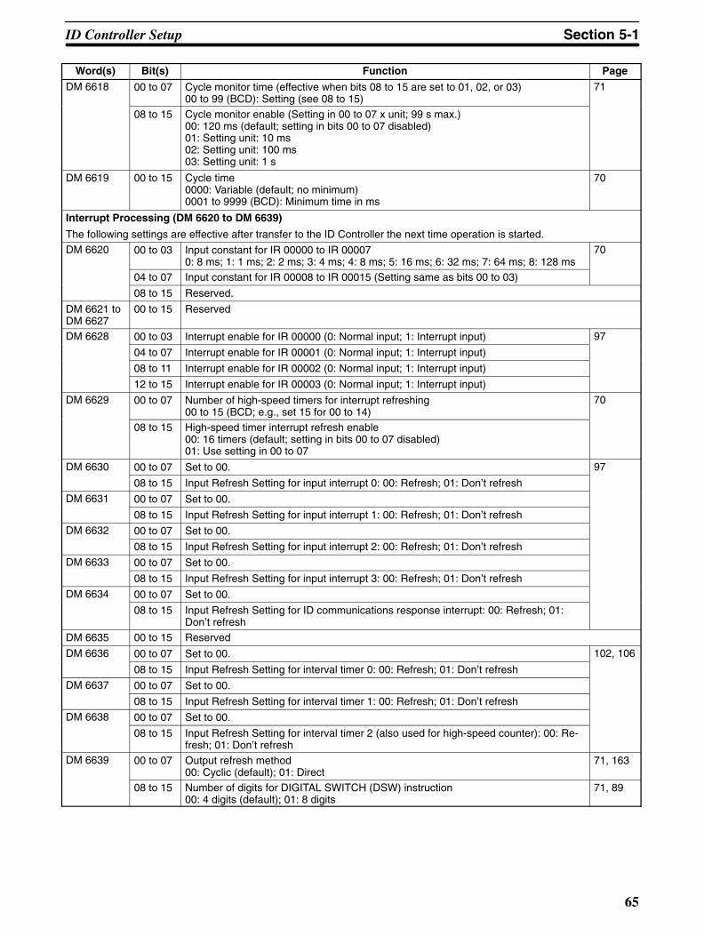
65
Word(s) PageFunctionBit(s)DM 6618 00 to 07 Cycle monitor time (effective when bits 08 to 15 are set to 01, 02, or 03)
00 to 99 (BCD): Setting (see 08 to 15)71
08 to 15 Cycle monitor enable (Setting in 00 to 07 x unit; 99 s max.)00: 120 ms (default; setting in bits 00 to 07 disabled)01: Setting unit: 10 ms02: Setting unit: 100 ms03: Setting unit: 1 s
DM 6619 00 to 15 Cycle time0000: Variable (default; no minimum) 0001 to 9999 (BCD): Minimum time in ms
70
Interrupt Processing (DM 6620 to DM 6639)
The following settings are effective after transfer to the ID Controller the next time operation is started.
DM 6620 00 to 03 Input constant for IR 00000 to IR 000070: 8 ms; 1: 1 ms; 2: 2 ms; 3: 4 ms; 4: 8 ms; 5: 16 ms; 6: 32 ms; 7: 64 ms; 8: 128 ms
70
04 to 07 Input constant for IR 00008 to IR 00015 (Setting same as bits 00 to 03)
08 to 15 Reserved.
DM 6621 toDM 6627
00 to 15 Reserved
DM 6628 00 to 03 Interrupt enable for IR 00000 (0: Normal input; 1: Interrupt input) 97
04 to 07 Interrupt enable for IR 00001 (0: Normal input; 1: Interrupt input)
08 to 11 Interrupt enable for IR 00002 (0: Normal input; 1: Interrupt input)
12 to 15 Interrupt enable for IR 00003 (0: Normal input; 1: Interrupt input)
DM 6629 00 to 07 Number of high-speed timers for interrupt refreshing00 to 15 (BCD; e.g., set 15 for 00 to 14)
70
08 to 15 High-speed timer interrupt refresh enable00: 16 timers (default; setting in bits 00 to 07 disabled)01: Use setting in 00 to 07
DM 6630 00 to 07 Set to 00. 97
08 to 15 Input Refresh Setting for input interrupt 0: 00: Refresh; 01: Don’t refresh
DM 6631 00 to 07 Set to 00.
08 to 15 Input Refresh Setting for input interrupt 1: 00: Refresh; 01: Don’t refresh
DM 6632 00 to 07 Set to 00.
08 to 15 Input Refresh Setting for input interrupt 2: 00: Refresh; 01: Don’t refresh
DM 6633 00 to 07 Set to 00.
08 to 15 Input Refresh Setting for input interrupt 3: 00: Refresh; 01: Don’t refresh
DM 6634 00 to 07 Set to 00.
08 to 15 Input Refresh Setting for ID communications response interrupt: 00: Refresh; 01:Don’t refresh
DM 6635 00 to 15 Reserved
DM 6636 00 to 07 Set to 00. 102, 106
08 to 15 Input Refresh Setting for interval timer 0: 00: Refresh; 01: Don’t refresh
,
DM 6637 00 to 07 Set to 00.
08 to 15 Input Refresh Setting for interval timer 1: 00: Refresh; 01: Don’t refresh
DM 6638 00 to 07 Set to 00.
08 to 15 Input Refresh Setting for interval timer 2 (also used for high-speed counter): 00: Re-fresh; 01: Don’t refresh
DM 6639 00 to 07 Output refresh method00: Cyclic (default); 01: Direct
71, 163
08 to 15 Number of digits for DIGITAL SWITCH (DSW) instruction00: 4 digits (default); 01: 8 digits
71, 89
ID Controller Setup Section 5-1
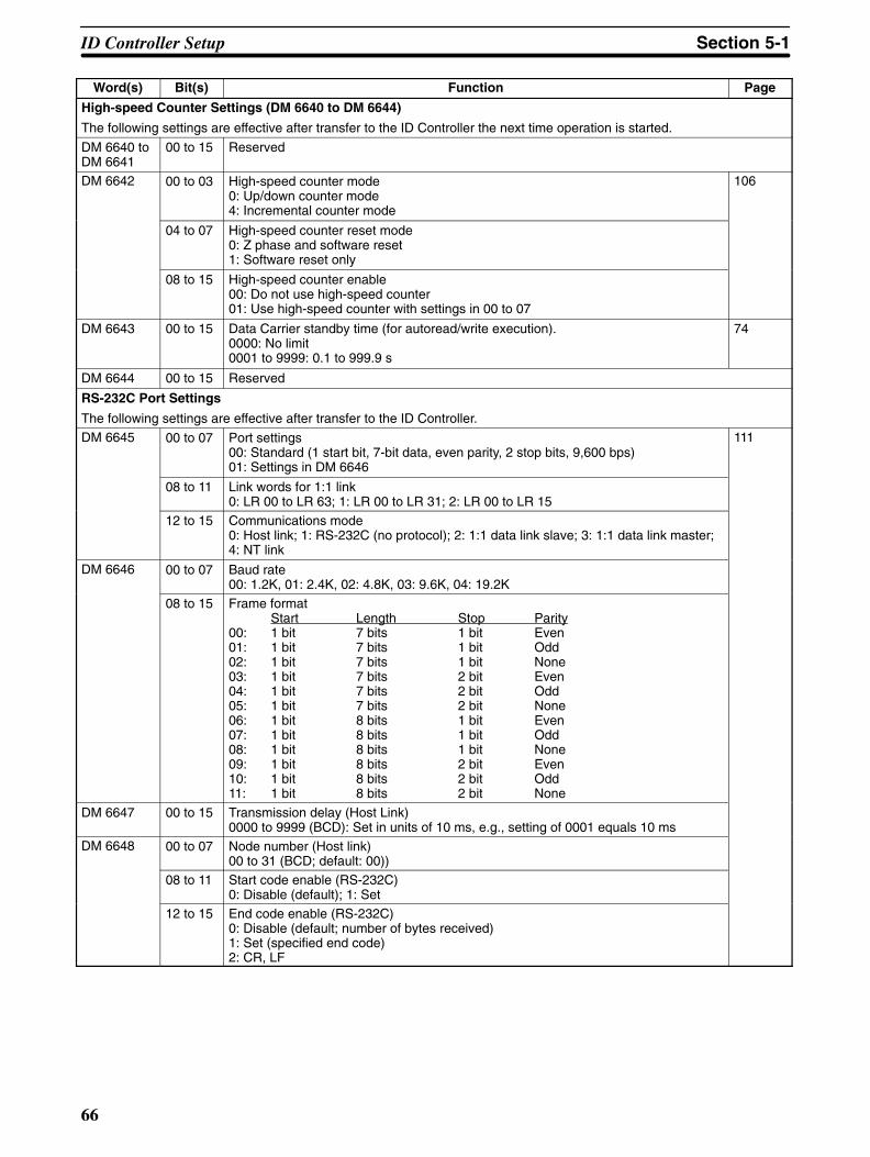
66
Word(s) PageFunctionBit(s)
High-speed Counter Settings (DM 6640 to DM 6644)
The following settings are effective after transfer to the ID Controller the next time operation is started.
DM 6640 toDM 6641
00 to 15 Reserved
DM 6642 00 to 03 High-speed counter mode0: Up/down counter mode4: Incremental counter mode
106
04 to 07 High-speed counter reset mode0: Z phase and software reset1: Software reset only
08 to 15 High-speed counter enable00: Do not use high-speed counter01: Use high-speed counter with settings in 00 to 07
DM 6643 00 to 15 Data Carrier standby time (for autoread/write execution).0000: No limit0001 to 9999: 0.1 to 999.9 s
74
DM 6644 00 to 15 Reserved
RS-232C Port Settings
The following settings are effective after transfer to the ID Controller.DM 6645 00 to 07 Port settings
00: Standard (1 start bit, 7-bit data, even parity, 2 stop bits, 9,600 bps)01: Settings in DM 6646
111
08 to 11 Link words for 1:1 link0: LR 00 to LR 63; 1: LR 00 to LR 31; 2: LR 00 to LR 15
12 to 15 Communications mode0: Host link; 1: RS-232C (no protocol); 2: 1:1 data link slave; 3: 1:1 data link master;4: NT link
DM 6646 00 to 07 Baud rate00: 1.2K, 01: 2.4K, 02: 4.8K, 03: 9.6K, 04: 19.2K
08 to 15 Frame formatStart Length Stop Parity
00: 1 bit 7 bits 1 bit Even01: 1 bit 7 bits 1 bit Odd02: 1 bit 7 bits 1 bit None03: 1 bit 7 bits 2 bit Even04: 1 bit 7 bits 2 bit Odd05: 1 bit 7 bits 2 bit None06: 1 bit 8 bits 1 bit Even07: 1 bit 8 bits 1 bit Odd08: 1 bit 8 bits 1 bit None09: 1 bit 8 bits 2 bit Even10: 1 bit 8 bits 2 bit Odd11: 1 bit 8 bits 2 bit None
DM 6647 00 to 15 Transmission delay (Host Link)0000 to 9999 (BCD): Set in units of 10 ms, e.g., setting of 0001 equals 10 ms
DM 6648 00 to 07 Node number (Host link)00 to 31 (BCD; default: 00))
08 to 11 Start code enable (RS-232C)0: Disable (default); 1: Set
12 to 15 End code enable (RS-232C)0: Disable (default; number of bytes received)1: Set (specified end code)2: CR, LF
ID Controller Setup Section 5-1
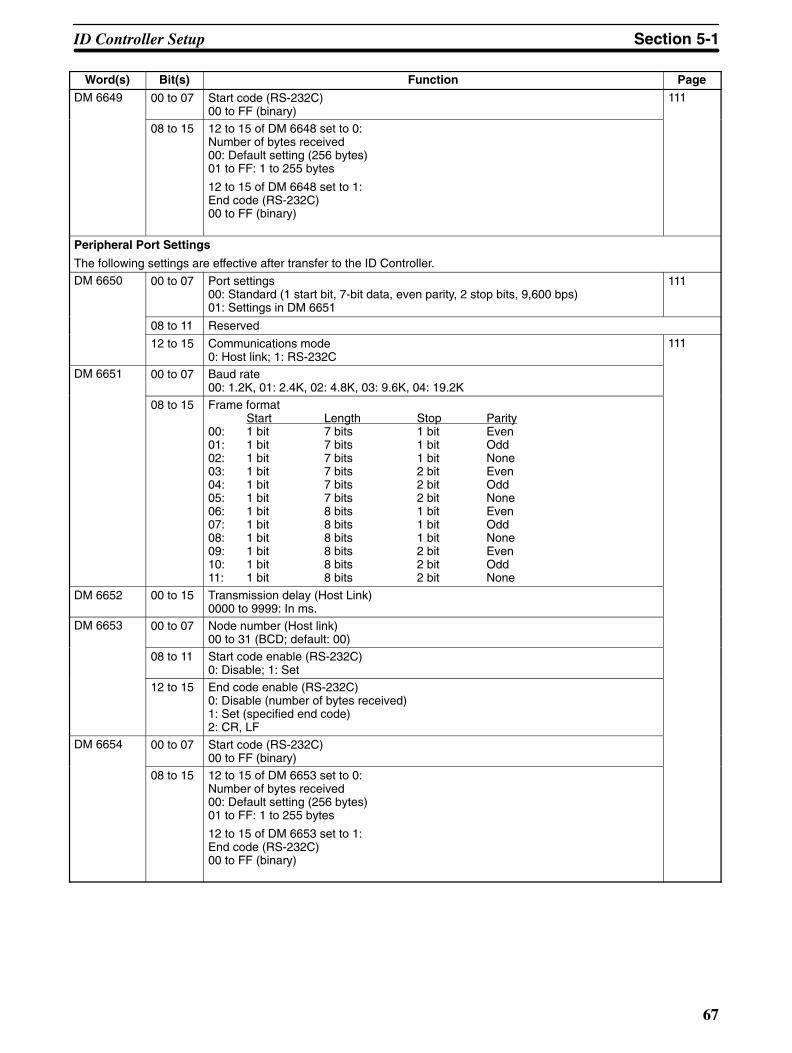
67
Word(s) PageFunctionBit(s)DM 6649 00 to 07 Start code (RS-232C)
00 to FF (binary)111
08 to 15 12 to 15 of DM 6648 set to 0:Number of bytes received00: Default setting (256 bytes)01 to FF: 1 to 255 bytes
12 to 15 of DM 6648 set to 1:End code (RS-232C)00 to FF (binary)
Peripheral Port Settings
The following settings are effective after transfer to the ID Controller.
DM 6650 00 to 07 Port settings00: Standard (1 start bit, 7-bit data, even parity, 2 stop bits, 9,600 bps)01: Settings in DM 6651
111
08 to 11 Reserved
12 to 15 Communications mode0: Host link; 1: RS-232C
111
DM 6651 00 to 07 Baud rate00: 1.2K, 01: 2.4K, 02: 4.8K, 03: 9.6K, 04: 19.2K
08 to 15 Frame formatStart Length Stop Parity
00: 1 bit 7 bits 1 bit Even01: 1 bit 7 bits 1 bit Odd02: 1 bit 7 bits 1 bit None03: 1 bit 7 bits 2 bit Even04: 1 bit 7 bits 2 bit Odd05: 1 bit 7 bits 2 bit None06: 1 bit 8 bits 1 bit Even07: 1 bit 8 bits 1 bit Odd08: 1 bit 8 bits 1 bit None09: 1 bit 8 bits 2 bit Even10: 1 bit 8 bits 2 bit Odd11: 1 bit 8 bits 2 bit None
DM 6652 00 to 15 Transmission delay (Host Link)0000 to 9999: In ms.
DM 6653 00 to 07 Node number (Host link)00 to 31 (BCD; default: 00)
08 to 11 Start code enable (RS-232C)0: Disable; 1: Set
12 to 15 End code enable (RS-232C)0: Disable (number of bytes received)1: Set (specified end code)2: CR, LF
DM 6654 00 to 07 Start code (RS-232C)00 to FF (binary)
08 to 15 12 to 15 of DM 6653 set to 0:Number of bytes received00: Default setting (256 bytes)01 to FF: 1 to 255 bytes
12 to 15 of DM 6653 set to 1:End code (RS-232C)00 to FF (binary)
ID Controller Setup Section 5-1

!
68
Word(s) PageFunctionBit(s)
Error Log Settings (DM 6655)
The following settings are effective after transfer to the ID Controller.DM 6655 00 to 03 Error Log Style
0: Shift after 10 records have been stored (default)1: Store only first 10 records (no shifting)2 to F: Do not store records
72
04 to 07 ID Error Log Style0: Shift after 30 records have been stored (default)1: Store only first 30 records (no shifting)2 to F: Do not store records
72
08 to 11 Cycle time monitor enable0: Detect long cycles as non-fatal errors (default)1: Do not detect long cycles
72
12 to 15 Low battery error enable0: Detect low battery voltage as non-fatal error (default)1: Do not detect low batter voltage
Default Values The default values for the ID Controller Setup are 0000 for all words. The defaultvalues can be reset at any time by turning ON SR 25210.
Caution When data memory (DM) is cleared from a Programming Device, the ID Control-ler Setup settings will also be cleared to all zeros.
Changing the Setup Changes in ID Controller Setup settings are effective and will affect ID Controlleroperation at various times depending on the setting, as described below.
DM 6600 to DM 6614: Effective when ID Controller power supply is turned on.DM 6615 to DM 6644: Effective when program execution begins.DM 6645 to DM 6655: Effective any time that ID Controller power is on.(DM 6611 and DM 6643 are read once when power is turned on and once whenprogram execution begins.)
Note Changes in the ID Controller Setup are effective only at the times given above.Be sure to take the proper measures to make changes effective before continu-ing operation.
Although the ID Controller Setup is stored in DM 6600 to DM 6655, settings canbe made and changed only from a Programming Device (e.g., LSS, SSS, or Pro-gramming Console). DM 6600 to DM 6644 can be set or changed only while inPROGRAM mode. DM 6645 to DM 6655 can be set or changed while in eitherPROGRAM mode or MONITOR mode.
Note The ID Controller Setup can be read, but not written into, from the user program.Writing can only be done by means of a Programming Device.
If a ID Controller Setup setting is improper, then a non-fatal error (error code 9B)will be generated when the ID Controller reads that setting, and the appropriatebit between AR 2400 and AR 2402 will turn ON. (The erroneous setting will beread at the default value.)
The following settings can be made in PROGRAM mode from the LSS/SSS us-ing menu operations. All other settings must be made using the hexadecimalsetting operation.
Startup Mode (DM 6600)I/O Hold Bit Status and Forced Status Hold Bit Status (DM 6601)Cycle Monitor Time (DM 6618)Cycle Time (DM 6619)RS-232C Port Settings (DM 6645 to DM 6649)
ID Controller Setup Section 5-1
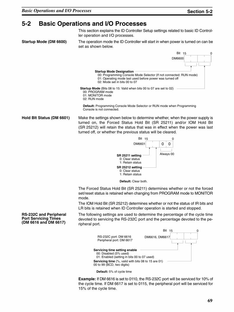
69
5-2 Basic Operations and I/O ProcessesThis section explains the ID Controller Setup settings related to basic ID Control-ler operation and I/O processes.
Startup Mode (DM 6600) The operation mode the ID Controller will start in when power is turned on can beset as shown below.
15Bit
DM6600
0
Startup Mode Designation00: Programming Console Mode Selector (If not connected: RUN mode)01: Operating mode last used before power was turned off02: Mode set in bits 00 to 07
Startup Mode (Bits 08 to 15: Valid when bits 00 to 07 are set to 02)00: PROGRAM mode01: MONITOR mode02: RUN mode
Default: Programming Console Mode Selector or RUN mode when ProgrammingConsole is not connected.
Hold BIt Status (DM 6601) Make the settings shown below to determine whether, when the power supply isturned on, the Forced Status Hold Bit (SR 25211) and/or IOM Hold Bit(SR 25212) will retain the status that was in effect when the power was lastturned off, or whether the previous status will be cleared.
15 0
0 0Bit
DM6601
SR 25211 setting0: Clear status1: Retain status
Always 00
SR 25212 setting0: Clear status1: Retain status
Default: Clear both.
The Forced Status Hold Bit (SR 25211) determines whether or not the forcedset/reset status is retained when changing from PROGRAM mode to MONITORmode.The IOM Hold Bit (SR 25212) determines whether or not the status of IR bits andLR bits is retained when ID Controller operation is started and stopped.
The following settings are used to determine the percentage of the cycle timedevoted to servicing the RS-232C port and the percentage devoted to the pe-ripheral port.
15 0Bit
Servicing time setting enable00: Disabled (5% used)01: Enabled (setting in bits 00 to 07 used)
Servicing time (%, valid with bits 08 to 15 are 01)00 to 99 (BCD, two digits)
Default: 5% of cycle time
DM6616, DM6617RS-232C port: DM 6616Peripheral port: DM 6617
Example: If DM 6616 is set to 0110, the RS-232C port will be serviced for 10% ofthe cycle time. If DM 6617 is set to 0115, the peripheral port will be serviced for15% of the cycle time.
RS-232C and PeripheralPort Servicing Times(DM 6616 and DM 6617)
Basic Operations and I/O Processes Section 5-2
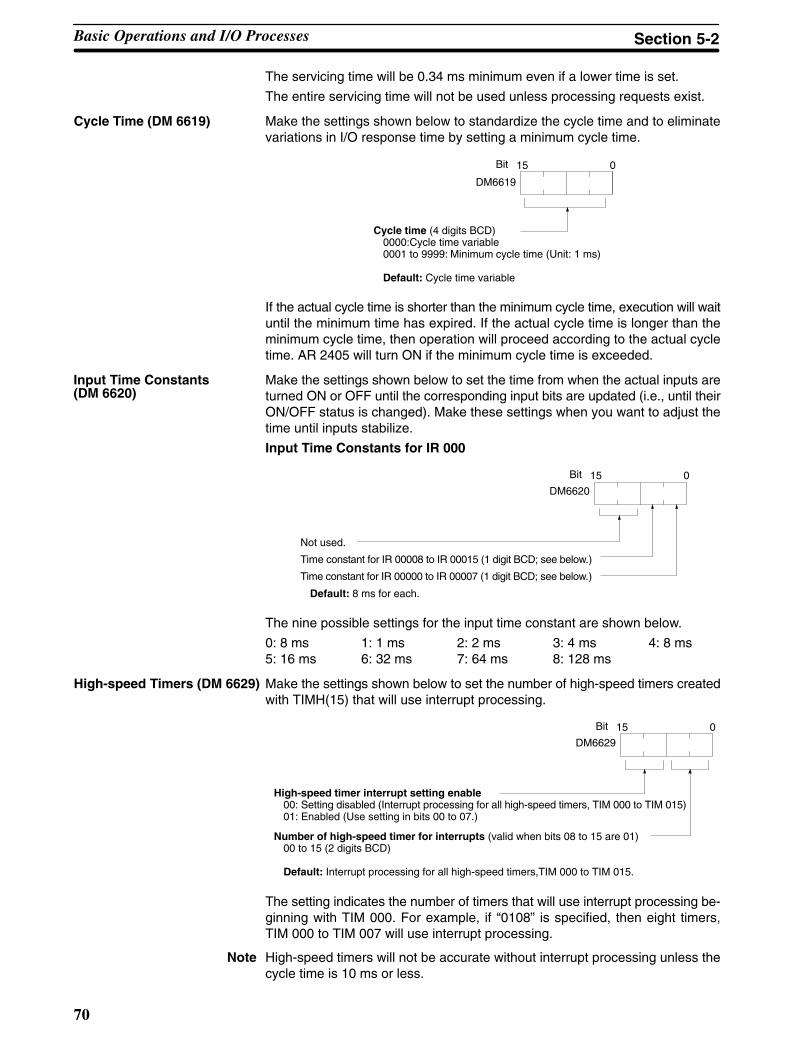
70
The servicing time will be 0.34 ms minimum even if a lower time is set.
The entire servicing time will not be used unless processing requests exist.
Cycle Time (DM 6619) Make the settings shown below to standardize the cycle time and to eliminatevariations in I/O response time by setting a minimum cycle time.
15 0Bit
DM6619
Cycle time (4 digits BCD)0000:Cycle time variable0001 to 9999: Minimum cycle time (Unit: 1 ms)
Default: Cycle time variable
If the actual cycle time is shorter than the minimum cycle time, execution will waituntil the minimum time has expired. If the actual cycle time is longer than theminimum cycle time, then operation will proceed according to the actual cycletime. AR 2405 will turn ON if the minimum cycle time is exceeded.
Make the settings shown below to set the time from when the actual inputs areturned ON or OFF until the corresponding input bits are updated (i.e., until theirON/OFF status is changed). Make these settings when you want to adjust thetime until inputs stabilize.
Input Time Constants for IR 000
15 0
DM6620
Bit
Not used.
Time constant for IR 00008 to IR 00015 (1 digit BCD; see below.)
Time constant for IR 00000 to IR 00007 (1 digit BCD; see below.)
Default: 8 ms for each.
The nine possible settings for the input time constant are shown below.
0: 8 ms 1: 1 ms 2: 2 ms 3: 4 ms 4: 8 ms5: 16 ms 6: 32 ms 7: 64 ms 8: 128 ms
High-speed Timers (DM 6629) Make the settings shown below to set the number of high-speed timers createdwith TIMH(15) that will use interrupt processing.
15 0
DM6629
Bit
High-speed timer interrupt setting enable00: Setting disabled (Interrupt processing for all high-speed timers, TIM 000 to TIM 015)01: Enabled (Use setting in bits 00 to 07.)
Number of high-speed timer for interrupts (valid when bits 08 to 15 are 01)00 to 15 (2 digits BCD)
Default: Interrupt processing for all high-speed timers,TIM 000 to TIM 015.
The setting indicates the number of timers that will use interrupt processing be-ginning with TIM 000. For example, if “0108” is specified, then eight timers,TIM 000 to TIM 007 will use interrupt processing.
Note High-speed timers will not be accurate without interrupt processing unless thecycle time is 10 ms or less.
Input Time Constants(DM 6620)
Basic Operations and I/O Processes Section 5-2
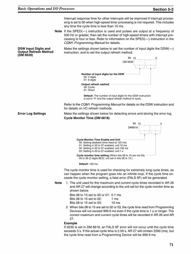
71
Interrupt response time for other interrupts will be improved if interrupt proces-sing is set to 00 when high-speed timer processing is not required. This includesany time the cycle time is less than 10 ms.
Note If the SPED(––) instruction is used and pulses are output at a frequency of500 Hz or greater, then set the number of high-speed timers with interrupt pro-cessing to four or less. Refer to information on the SPED(––) instruction in theCQM1 Programming Manual for details.
Make the settings shown below to set the number of input digits the DSW(––)instruction, and to set the output refresh method.
15 0
DM 6639
Bit
Number of input digits for the DSW00: 4 digits01: 8 digits
Output refresh method00: Cyclic01: Direct
Default: The number of input digits for the DSW instructionis set to “4” and the output refresh method is cyclic.
Refer to the CQM1 Programming Manual for details on the DSW instruction andfor details on I/O refresh methods.
Error Log Settings Make the settings shown below for detecting errors and storing the error log.Cycle Monitor Time (DM 6618)
15 0
DM6618
Bit
Cycle Monitor Time Enable and Unit00: Setting disabled (time fixed at 120 ms)01: Setting in 00 to 07 enabled; unit:10 ms02: Setting in 00 to 07 enabled; unit:100 ms03: Setting in 00 to 07 enabled; unit:1 s
Cycle monitor time setting (When bits 08 to 15 are not 00)00 to 99 (2 digits BCD; unit set in bits 08 to 15.)
Default: 120 ms.
The cycle monitor time is used for checking for extremely long cycle times, ascan happen when the program goes into an infinite loop. If the cycle time ex-ceeds the cycle monitor setting, a fatal error (FALS 9F) will be generated.
Note 1. The unit used for the maximum and current cycle times recorded in AR 26and AR 27 will change according to the unit set for the cycle monitor time asshown below.Bits 08 to 15 set to 00 or 01: 0.1 msBits 08 to 15 set to 02: 1 msBits 08 to 15 set to 03: 10 ms
2. When bits 08 to 15 are set to 02 or 03, the cycle time read from ProgrammingDevices will not exceed 999.9 ms even if the cycle time is 1 s or longer. Thecorrect maximum and current cycle times will be recorded in AR 26 and AR27.
ExampleIf 0230 is set in DM 6618, an FALS 9F error will not occur until the cycle timeexceeds 3 s. If the actual cycle time is 2.59 s, AR 27 will contain 2590 (ms), butthe cycle time read from a Programming Device will be 999.9 ms.
DSW Input Digits andOutput Refresh Method(DM 6639)
Basic Operations and I/O Processes Section 5-2
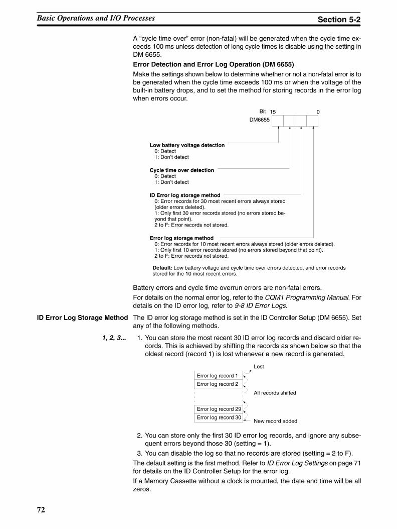
72
A “cycle time over” error (non-fatal) will be generated when the cycle time ex-ceeds 100 ms unless detection of long cycle times is disable using the setting inDM 6655.
Error Detection and Error Log Operation (DM 6655)Make the settings shown below to determine whether or not a non-fatal error is tobe generated when the cycle time exceeds 100 ms or when the voltage of thebuilt-in battery drops, and to set the method for storing records in the error logwhen errors occur.
Low battery voltage detection0: Detect1: Don’t detect
Cycle time over detection0: Detect1: Don’t detect
ID Error log storage method0: Error records for 30 most recent errors always stored(older errors deleted).1: Only first 30 error records stored (no errors stored be-yond that point).2 to F: Error records not stored.
Error log storage method0: Error records for 10 most recent errors always stored (older errors deleted).1: Only first 10 error records stored (no errors stored beyond that point).2 to F: Error records not stored.
15 0
DM6655
Bit
Default: Low battery voltage and cycle time over errors detected, and error recordsstored for the 10 most recent errors.
Battery errors and cycle time overrun errors are non-fatal errors.
For details on the normal error log, refer to the CQM1 Programming Manual. Fordetails on the ID error log, refer to 9-8 ID Error Logs.
ID Error Log Storage Method The ID error log storage method is set in the ID Controller Setup (DM 6655). Setany of the following methods.
1, 2, 3... 1. You can store the most recent 30 ID error log records and discard older re-cords. This is achieved by shifting the records as shown below so that theoldest record (record 1) is lost whenever a new record is generated.
Error log record 29
Error log record 30
Error log record 1
Error log record 2
Lost
New record added
All records shifted
2. You can store only the first 30 ID error log records, and ignore any subse-quent errors beyond those 30 (setting = 1).
3. You can disable the log so that no records are stored (setting = 2 to F).
The default setting is the first method. Refer to ID Error Log Settings on page 71for details on the ID Controller Setup for the error log.
If a Memory Cassette without a clock is mounted, the date and time will be allzeros.
Basic Operations and I/O Processes Section 5-2
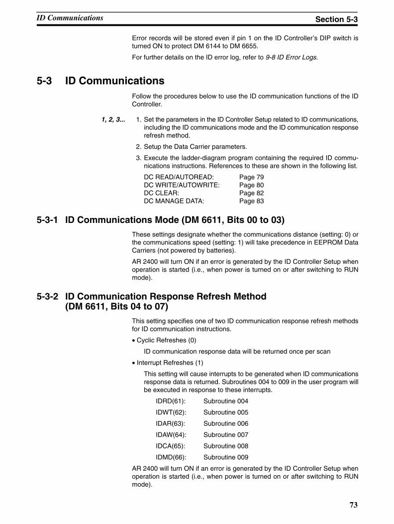
73
Error records will be stored even if pin 1 on the ID Controller’s DIP switch isturned ON to protect DM 6144 to DM 6655.
For further details on the ID error log, refer to 9-8 ID Error Logs.
5-3 ID CommunicationsFollow the procedures below to use the ID communication functions of the IDController.
1, 2, 3... 1. Set the parameters in the ID Controller Setup related to ID communications,including the ID communications mode and the ID communication responserefresh method.
2. Setup the Data Carrier parameters.
3. Execute the ladder-diagram program containing the required ID commu-nications instructions. References to these are shown in the following list.
DC READ/AUTOREAD: Page 79DC WRITE/AUTOWRITE: Page 80DC CLEAR: Page 82DC MANAGE DATA: Page 83
5-3-1 ID Communications Mode (DM 6611, Bits 00 to 03)These settings designate whether the communications distance (setting: 0) orthe communications speed (setting: 1) will take precedence in EEPROM DataCarriers (not powered by batteries).
AR 2400 will turn ON if an error is generated by the ID Controller Setup whenoperation is started (i.e., when power is turned on or after switching to RUNmode).
5-3-2 ID Communication Response Refresh Method(DM 6611, Bits 04 to 07)
This setting specifies one of two ID communication response refresh methodsfor ID communication instructions.
• Cyclic Refreshes (0)
ID communication response data will be returned once per scan
• Interrupt Refreshes (1)
This setting will cause interrupts to be generated when ID communicationsresponse data is returned. Subroutines 004 to 009 in the user program willbe executed in response to these interrupts.
IDRD(61): Subroutine 004
IDWT(62): Subroutine 005
IDAR(63): Subroutine 006
IDAW(64): Subroutine 007
IDCA(65): Subroutine 008
IDMD(66): Subroutine 009
AR 2400 will turn ON if an error is generated by the ID Controller Setup whenoperation is started (i.e., when power is turned on or after switching to RUNmode).
ID Communications Section 5-3
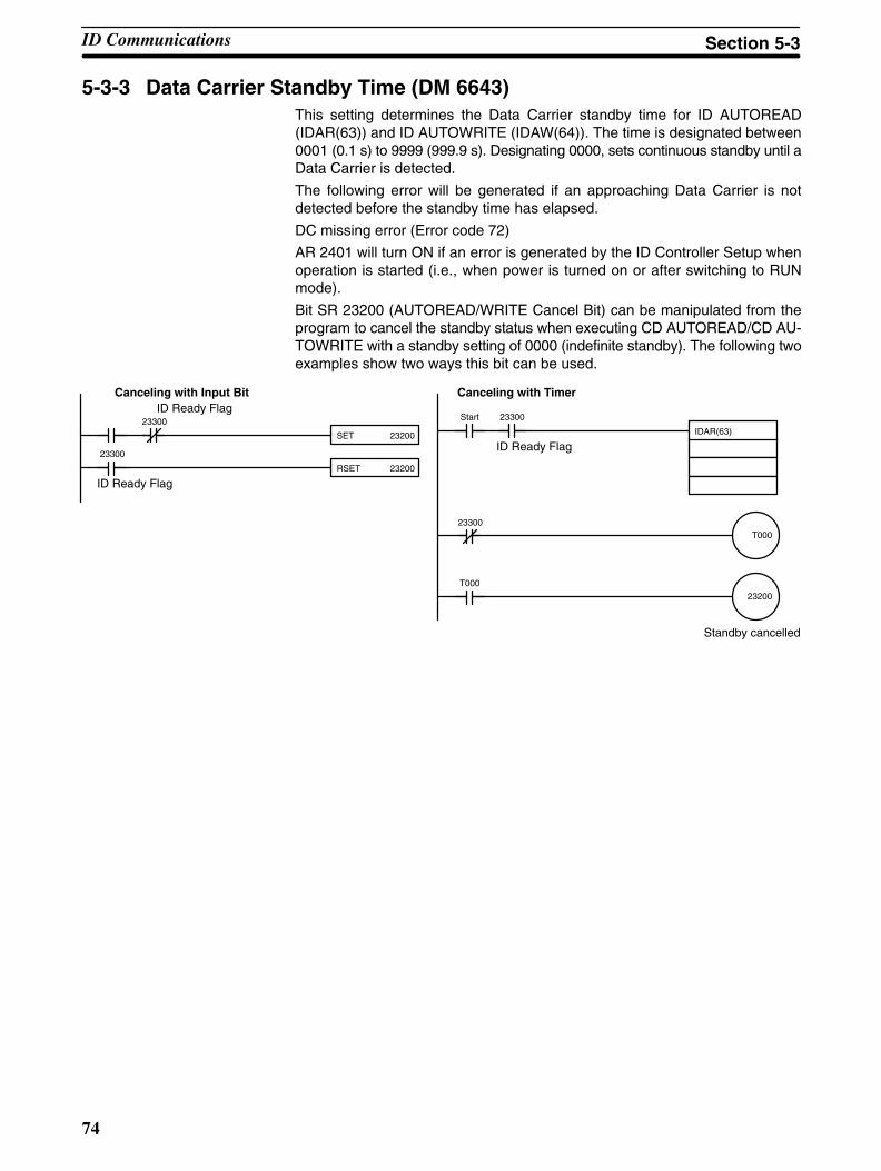
74
5-3-3 Data Carrier Standby Time (DM 6643)This setting determines the Data Carrier standby time for ID AUTOREAD(IDAR(63)) and ID AUTOWRITE (IDAW(64)). The time is designated between0001 (0.1 s) to 9999 (999.9 s). Designating 0000, sets continuous standby until aData Carrier is detected.
The following error will be generated if an approaching Data Carrier is notdetected before the standby time has elapsed.
DC missing error (Error code 72)
AR 2401 will turn ON if an error is generated by the ID Controller Setup whenoperation is started (i.e., when power is turned on or after switching to RUNmode).
Bit SR 23200 (AUTOREAD/WRITE Cancel Bit) can be manipulated from theprogram to cancel the standby status when executing CD AUTOREAD/CD AU-TOWRITE with a standby setting of 0000 (indefinite standby). The following twoexamples show two ways this bit can be used.
Canceling with Input Bit Canceling with TimerID Ready Flag
ID Ready Flag
ID Ready Flag
Standby cancelled
SET 23200
RSET 23200
IDAR(63)
23200
T000
23300
23300
Start 23300
23300
T000
ID Communications Section 5-3
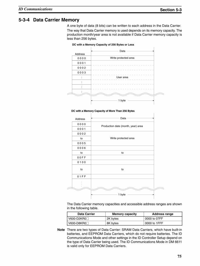
75
5-3-4 Data Carrier MemoryA one byte of data (8 bits) can be written to each address in the Data Carrier.The way that Data Carrier memory is used depends on its memory capacity. Theproduction month/year area is not available if Data Carrier memory capacity isless than 256 bytes.
0 0 0 0
0 0 0 1
0 0 0 2
0 0 0 3
:
:
:
:
AddressWrite protected area
User area
1 byte
Data
DC with a Memory Capacity of 256 Bytes or Less
0 0 0 0
0 0 0 1
0 0 0 2
to
0 0 0 5
0 0 0 6
to
0 0 F F
0 1 0 0
to
0 1 F F
to
to
Production date (month, year) area
Address Data
Write protected area
DC with a Memory Capacity of More Than 256 Bytes
1 byte
The Data Carrier memory capacities and accessible address ranges are shownin the following table.
Data Carrier Memory capacity Address range
V600-D2KR0 2K bytes 0000 to 07FF
V600-D8KR0 8K bytes 0000 to 1FFF
Note There are two types of Data Carrier: SRAM Data Carriers, which have built-inbatteries, and EEPROM Data Carriers, which do not require batteries. The IDCommunications Mode and other settings in the ID Controller Setup depend onthe type of Data Carrier being used. The ID Communications Mode in DM 6611is valid only for EEPROM Data Carriers.
ID Communications Section 5-3
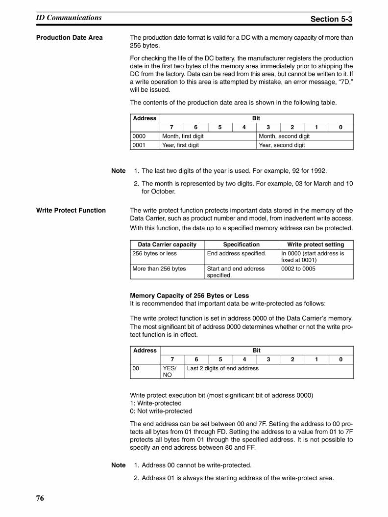
76
Production Date Area The production date format is valid for a DC with a memory capacity of more than256 bytes.
For checking the life of the DC battery, the manufacturer registers the productiondate in the first two bytes of the memory area immediately prior to shipping theDC from the factory. Data can be read from this area, but cannot be written to it. Ifa write operation to this area is attempted by mistake, an error message, “7D,”will be issued.
The contents of the production date area is shown in the following table.
Address Bit
7 6 5 4 3 2 1 0
0000 Month, first digit Month, second digit
0001 Year, first digit Year, second digit
Note 1. The last two digits of the year is used. For example, 92 for 1992.
2. The month is represented by two digits. For example, 03 for March and 10for October.
Write Protect Function The write protect function protects important data stored in the memory of theData Carrier, such as product number and model, from inadvertent write access.
With this function, the data up to a specified memory address can be protected.
Data Carrier capacity Specification Write protect setting
256 bytes or less End address specified. In 0000 (start address isfixed at 0001)
More than 256 bytes Start and end addressspecified.
0002 to 0005
Memory Capacity of 256 Bytes or LessIt is recommended that important data be write-protected as follows:
The write protect function is set in address 0000 of the Data Carrier’s memory.The most significant bit of address 0000 determines whether or not the write pro-tect function is in effect.
Address Bit
7 6 5 4 3 2 1 0
00 YES/NO
Last 2 digits of end address
Write protect execution bit (most significant bit of address 0000) 1: Write-protected 0: Not write-protected
The end address can be set between 00 and 7F. Setting the address to 00 pro-tects all bytes from 01 through FD. Setting the address to a value from 01 to 7Fprotects all bytes from 01 through the specified address. It is not possible tospecify an end address between 80 and FF.
Note 1. Address 00 cannot be write-protected.
2. Address 01 is always the starting address of the write-protect area.
ID Communications Section 5-3

!
77
Memory Capacity of More Than 256 Bytes It is recommended that important data be write-protected as follows:
The write protect function is set in addresses 0002 to 0005 of the Data Carrier’smemory. The most significant bit of address 0002 determines whether or not thewrite protect function is in effect.
Address Bit
7 6 5 4 3 2 1 0
0002 YES/NO
First (leftmost) 2 digits of start address
0003 Last (rightmost) 2 digits of start address
0004 First (leftmost) 2 digits of end address
0005 Last (rightmost) 2 digits of end address
Write protect execution bit (most significant bit of address 0002) 1: Write-protected 0: Not write-protected
The start address can be set between 0006 and 7FFF. The end address can beset between 0006 and FFFF.
Note 1. If the setting of the end address exceeds the last address in the Data Carrier,protection will still be in effect through the last address.
2. If the start address is larger than the end address, two areas will be pro-tected: from 0006 through the end address and from the start addressthrough the last address in the Data Carrier.
5-3-5 Data Carrier Life Detection Functions
SRAM Data Carriers A check on the service life of batteries can be executed by reading two bytes ofdata from an address between 0000 to 0001 of the Data Carrier. After the data isread, the results of the battery check will be reflected in the status of SR 23306(DC Battery Warning Flag). This flag will be turned ON when the service life ofthe battery is at an end and will be OFF if the battery is still normal.
The service life of Data Carrier battery is checked by running a fixed currentmomentarily through the internal circuits of the Data Carrier. The battery thus willbe quickly consumed if a service life check of the batteries is executed everytime a Data Carrier is accessed. We recommend a routine check once a day inthe system program.
Caution In a service life check on the battery of a Data Carrier that has been sittingaround unused for several months, the DC battery service life warning may beON even if the battery is still serviceable. Therefore, execute a read operation for10 minutes to activate the batteries before conducting a check on Data Carriersthat have been sitting around for an extended amount of time.
EEPROM Data Carriers The DC MANAGE DATA (IDMD(66)) instruction can be used to determinewhether the EEPROM overwrite count has been exceeded.
When the IDMD(66) instruction is executed, the results are reflected in the sta-tus of SR 23307 (ID Check Warning Flag).
ID Communications Section 5-3
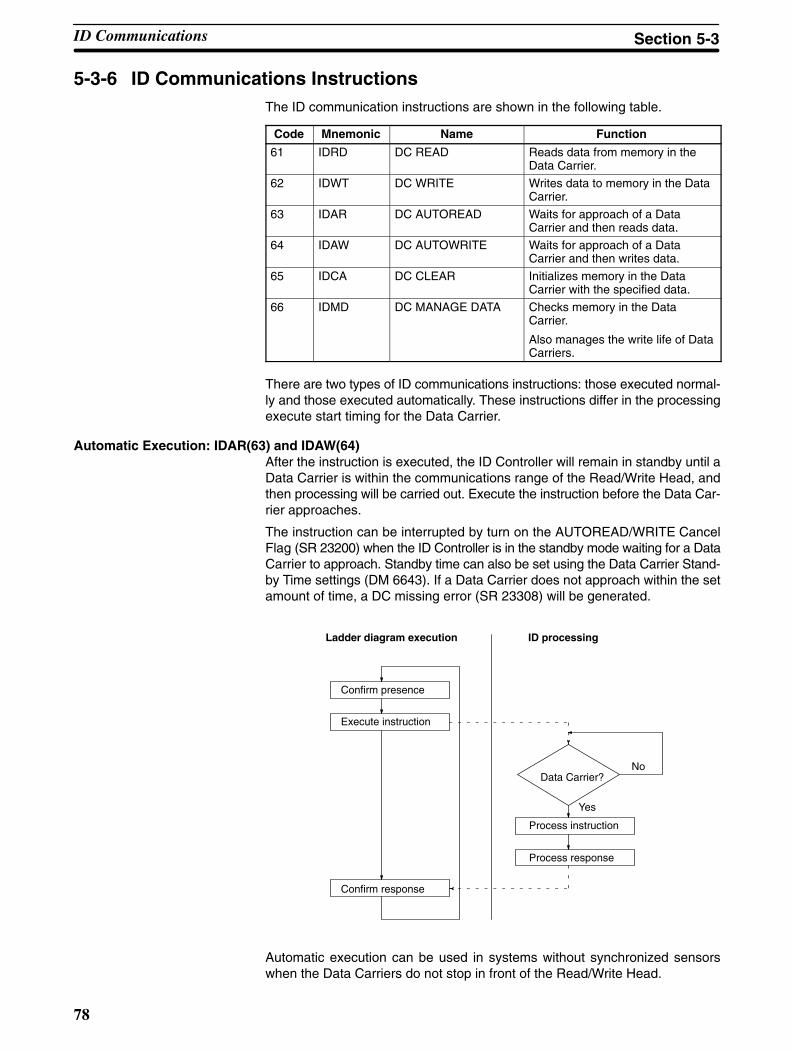
78
5-3-6 ID Communications InstructionsThe ID communication instructions are shown in the following table.
Code Mnemonic Name Function
61 IDRD DC READ Reads data from memory in theData Carrier.
62 IDWT DC WRITE Writes data to memory in the DataCarrier.
63 IDAR DC AUTOREAD Waits for approach of a DataCarrier and then reads data.
64 IDAW DC AUTOWRITE Waits for approach of a DataCarrier and then writes data.
65 IDCA DC CLEAR Initializes memory in the DataCarrier with the specified data.
66 IDMD DC MANAGE DATA Checks memory in the DataCarrier.
Also manages the write life of DataCarriers.
There are two types of ID communications instructions: those executed normal-ly and those executed automatically. These instructions differ in the processingexecute start timing for the Data Carrier.
Automatic Execution: IDAR(63) and IDAW(64)After the instruction is executed, the ID Controller will remain in standby until aData Carrier is within the communications range of the Read/Write Head, andthen processing will be carried out. Execute the instruction before the Data Car-rier approaches.
The instruction can be interrupted by turn on the AUTOREAD/WRITE CancelFlag (SR 23200) when the ID Controller is in the standby mode waiting for a DataCarrier to approach. Standby time can also be set using the Data Carrier Stand-by Time settings (DM 6643). If a Data Carrier does not approach within the setamount of time, a DC missing error (SR 23308) will be generated.
Ladder diagram execution ID processing
Execute instruction
Confirm response
Data Carrier?No
Yes
Process instruction
Process response
Confirm presence
Automatic execution can be used in systems without synchronized sensorswhen the Data Carriers do not stop in front of the Read/Write Head.
ID Communications Section 5-3

79
Normal Execution: IDRD(61), IDWT(62), IDCA(65), and IDMD(66)When the instruction is executed, processing is carried out only if a Data Carrieris present within the communications range of the Read/Write Head. If no DataCarrier is present, a DC missing error (SR 23308) will be generated. Execute theinstruction after making sure that a Data Carrier is present.
Ladder diagram execution ID processing
Execute instruction
Confirm response
Data Carrier?No
Yes
Process instruction
Process response
Confirm presence
Use normal execution when a Data Carrier is stopped in front of the Read/WriteHead.
5-3-7 Reading Data Carriers –– IDRD(61)/IDAR(63)The DC READ (IDRD(61)) and DC AUTOREAD (IDAR(63)) instructions areused to read data from a Data Carrier. The maximum amount of data that can beread each time an instruction is executed is 256 bytes.
IDRD(61) reads data from the Data Carrier memory (S: first address) and storesthe data in the ID Controller memory (D: first word).
IDAR(63) places execution of the read operation on standby until a Data Carrieris detected. It then reads data from Data Carrier memory and stores the data inthe ID Controller.
Using the Instruction
(@) IDRD(61)
S
C
D
S: First source address in DC (4-digit HEX)
C: Control data (number of bytes)
D: First destination word in ID Controller
(@) IDAR(63)
S
C
D
Refer to page 134 for further details on control data.
Note Data returned from reads can be processed return once per scan using cyclicrefreshes or it can be processed via interrupts generated at the end of commu-nications with the Data Carrier (interrupt refreshes). Set the ID communicationsresponse refresh method in DM 6611, bits 04 to 07. With the interrupt refreshmethod, subroutines 004 to 009 of the user program can be executed.
Example The following example reads five bytes of data starting at address $0010 of theData Carrier and stores the data starting at DM 0100 in the ID Controller.
If SR 23300 (ID Ready Flag) is ON when input IR 00100 turns ON, 5 bytes of dataare read starting from address $0010 to and written starting at DM 0100. Thedata is stored with the most significant bytes first.
ID Communications Section 5-3
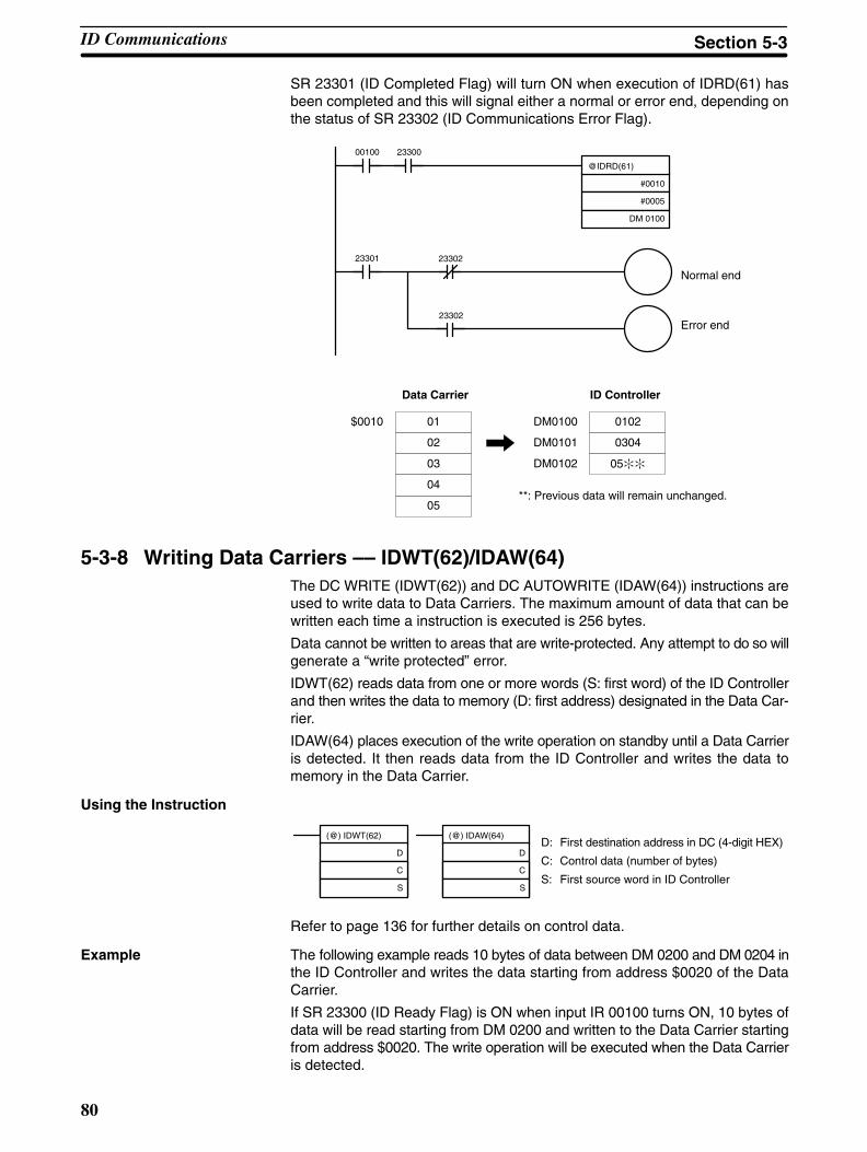
80
SR 23301 (ID Completed Flag) will turn ON when execution of IDRD(61) hasbeen completed and this will signal either a normal or error end, depending onthe status of SR 23302 (ID Communications Error Flag).
Normal end
Error end
@IDRD(61)
#0010
#0005
DM 0100
00100 23300
23301 23302
23302
Data Carrier ID Controller
**: Previous data will remain unchanged.
$0010 01
02
03
04
05
DM0100 0102
0304
05
DM0101
DM0102
5-3-8 Writing Data Carriers –– IDWT(62)/IDAW(64)The DC WRITE (IDWT(62)) and DC AUTOWRITE (IDAW(64)) instructions areused to write data to Data Carriers. The maximum amount of data that can bewritten each time a instruction is executed is 256 bytes.
Data cannot be written to areas that are write-protected. Any attempt to do so willgenerate a “write protected” error.
IDWT(62) reads data from one or more words (S: first word) of the ID Controllerand then writes the data to memory (D: first address) designated in the Data Car-rier.
IDAW(64) places execution of the write operation on standby until a Data Carrieris detected. It then reads data from the ID Controller and writes the data tomemory in the Data Carrier.
Using the Instruction
(@) IDWT(62)
D
C
S
D: First destination address in DC (4-digit HEX)
C: Control data (number of bytes)
S: First source word in ID Controller
(@) IDAW(64)
D
C
S
Refer to page 136 for further details on control data.
Example The following example reads 10 bytes of data between DM 0200 and DM 0204 inthe ID Controller and writes the data starting from address $0020 of the DataCarrier.
If SR 23300 (ID Ready Flag) is ON when input IR 00100 turns ON, 10 bytes ofdata will be read starting from DM 0200 and written to the Data Carrier startingfrom address $0020. The write operation will be executed when the Data Carrieris detected.
ID Communications Section 5-3
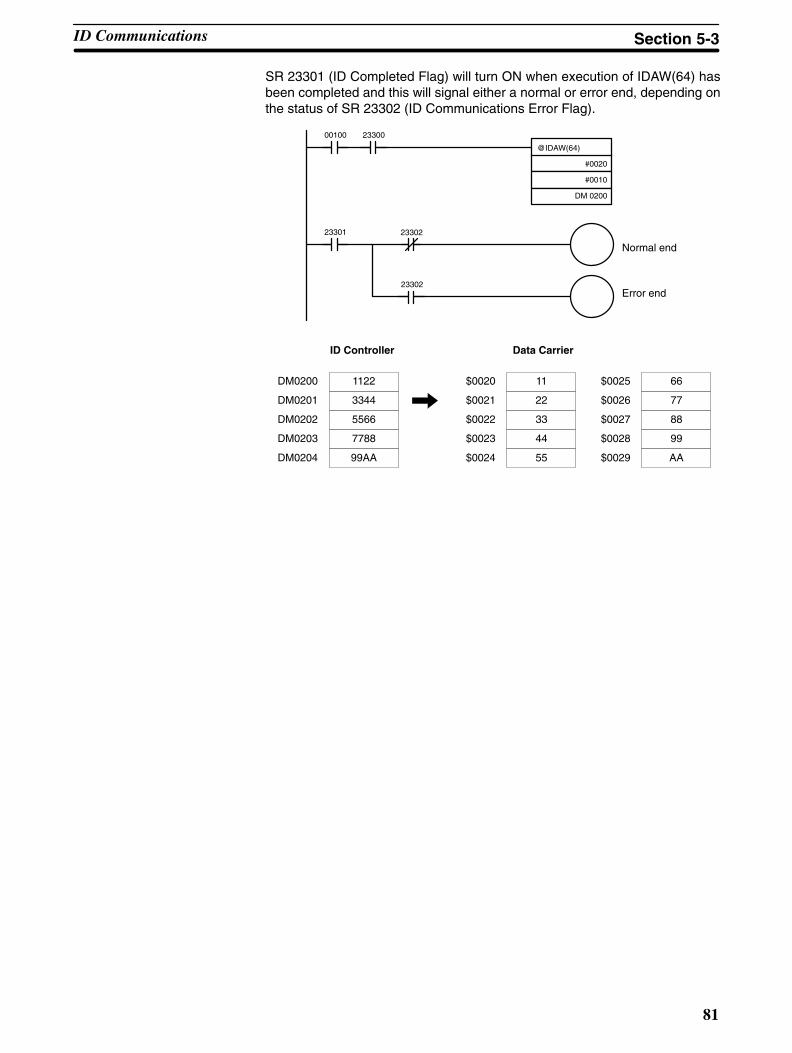
81
SR 23301 (ID Completed Flag) will turn ON when execution of IDAW(64) hasbeen completed and this will signal either a normal or error end, depending onthe status of SR 23302 (ID Communications Error Flag).
Normal end
Error end
@IDAW(64)
#0020
#0010
DM 0200
00100 23300
23301 23302
23302
Data CarrierID Controller
DM0200 1122
3344
5566
7788
99AA
DM0201
DM0202
DM0203
DM0204
$0025 66
77
88
$0026
$0027
99
AA
$0028
$0029
$0020 11
22
33
$0021
$0022
44
55
$0023
$0024
ID Communications Section 5-3

!
82
5-3-9 Cancelling DC AUTOREAD and DC AUTOWRITEThe AUTOREAD/WRITE Cancel Bit (SR 23200) is used to cancel read/write op-erations that are waiting for detection of a Data Carrier when IDAW(64) orIDAR(63) is executed.
ExampleThe following example shows how to cancel processing while a read initiated byDC AUTOREAD (IDAR(63)) is in progress for 5 bytes of data starting fromaddress $0010 of the Data Carrier.
If SR 23300 (ID Ready Flag) is ON when input IR 00100 turns ON, IDAR(63) willbe executed and execution of the read operation will wait for detection of a DataCarrier.
The AUTOREAD/WRITE Cancel Bit (SR 23200) will turn ON when IR 00101turns ON, canceling the read operation.
After the read operation is canceled, SR 23300 (ID Ready Flag) will turn ON,turning OFF the AUTOREAD/WRITE Cancel Bit (SR 23200).
@IDAR(63)
#0010
#0005
DM 0100
00100 23300
23200
23200
23300
DIFU(13) 00102
00101
00102
Caution The data at the specified destination word(s) or address(es) will not be overwrit-ten if IDAR(63) or IDAW(64) processing is cancelled.
5-3-10 Clearing Data Carriers –– IDCA(65)The DC CLEAR (IDCA(65)) instruction initializes the memory (D: first address)of the Data Carrier with designated data (S: word or constant). All data in desig-nated user areas will be initialized whether the area is write-protected or not.
Using the Instruction
D: First destination address in DC (4-digit HEX)
C: Control data (number of bytes; 0000: end of memory)
S: Source word in ID Controller or constant
(@) IDCA(65)
D
C
S
Refer to page 137 for further details on control data.
Example The following example shows how to initialize all Data Carrier data with $00.
If SR 23300 (ID Ready Flag) is ON when input IR 00100 turns ON, all addresses(i.e., from $0000 to the last address except the production month/year) will becleared to 00.
ID Communications Section 5-3
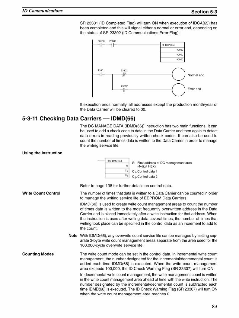
83
SR 23301 (ID Completed Flag) will turn ON when execution of IDCA(65) hasbeen completed and this will signal either a normal or error end, depending onthe status of SR 23302 (ID Communications Error Flag).
Normal end
Error end
@IDCA(65)
#0000
#0000
#0000
00100 23300
23301 23302
23302
If execution ends normally, all addresses except the production month/year ofthe Data Carrier will be cleared to 00.
5-3-11 Checking Data Carriers –– IDMD(66)The DC MANAGE DATA (IDMD(66)) instruction has two main functions. It canbe used to add a check code to data in the Data Carrier and then again to detectdata errors in reading previously written check codes. It can also be used tocount the number of times data is written to the Data Carrier in order to managethe writing service life.
Using the Instruction
S: First address of DC management area (4-digit HEX)
C1: Control data 1
C2: Control data 2
(@) IDMD(66)
S
C1
C2
Refer to page 138 for further details on control data.
Write Count Control The number of times that data is written to a Data Carrier can be counted in orderto manage the writing service life of EEPROM Data Carriers.
IDMD(66) is used to create write count management areas to count the numberof times data is written to the most frequently overwritten address in the DataCarrier and is placed immediately after a write instruction for that address. Whenthe instruction is used after writing data several times, the number of times thatwriting took place can be specified in the control data as an increment to add tothe count.
Note With IDMD(66), any overwrite count service life can be managed by setting sep-arate 3-byte write count management areas separate from the area used for the100,000-cycle overwrite service life.
Counting Modes The write count mode can be set in the control data. In incremental write countmanagement, the number designated for the incremental/decremental count isadded each time IDMD(66) is executed. When the write count managementarea exceeds 100,000, the ID Check Warning Flag (SR 23307) will turn ON.
In decremental write count management, the write management count is writtenin the write count management area ahead of time with the write instruction. Thenumber designated by the incremental/decremental count is subtracted eachtime IDMD(66) is executed. The ID Check Warning Flag (SR 23307) will turn ONwhen the write count management area reaches 0.
ID Communications Section 5-3
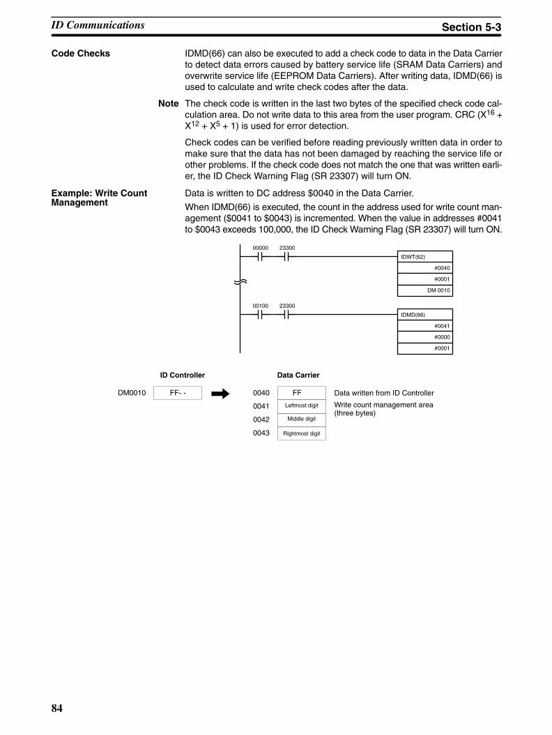
84
Code Checks IDMD(66) can also be executed to add a check code to data in the Data Carrierto detect data errors caused by battery service life (SRAM Data Carriers) andoverwrite service life (EEPROM Data Carriers). After writing data, IDMD(66) isused to calculate and write check codes after the data.
Note The check code is written in the last two bytes of the specified check code cal-culation area. Do not write data to this area from the user program. CRC (X16 +X12 + X5 + 1) is used for error detection.
Check codes can be verified before reading previously written data in order tomake sure that the data has not been damaged by reaching the service life orother problems. If the check code does not match the one that was written earli-er, the ID Check Warning Flag (SR 23307) will turn ON.
Data is written to DC address $0040 in the Data Carrier.
When IDMD(66) is executed, the count in the address used for write count man-agement ($0041 to $0043) is incremented. When the value in addresses #0041to $0043 exceeds 100,000, the ID Check Warning Flag (SR 23307) will turn ON.
IDWT(62)
#0040
#0001
DM 0010
IDMD(66)
#0041
#0000
#0001
00000 23300
00100 23300
ID Controller Data Carrier
Data written from ID Controller
Write count management area(three bytes)
DM0010 FF- - 0040 FF
Leftmost digit
Middle digit
0041
0042
Rightmost digit0043
Example: Write CountManagement
ID Communications Section 5-3
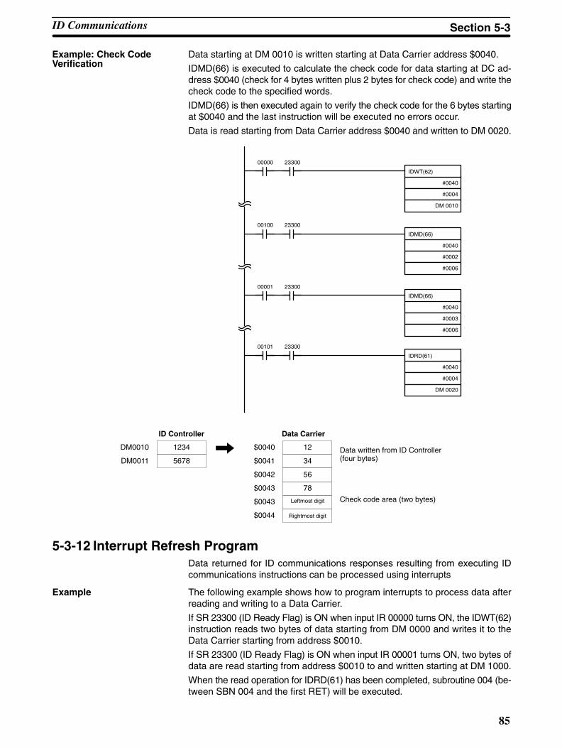
85
Data starting at DM 0010 is written starting at Data Carrier address $0040.
IDMD(66) is executed to calculate the check code for data starting at DC ad-dress $0040 (check for 4 bytes written plus 2 bytes for check code) and write thecheck code to the specified words.
IDMD(66) is then executed again to verify the check code for the 6 bytes startingat $0040 and the last instruction will be executed no errors occur.
Data is read starting from Data Carrier address $0040 and written to DM 0020.
IDWT(62)
#0040
#0004
DM 0010
00000 23300
IDMD(66)
#0040
#0002
#0006
00100 23300
IDMD(66)
#0040
#0003
#0006
00001 23300
IDRD(61)
#0040
#0004
DM 0020
00101 23300
ID Controller Data Carrier
Data written from ID Controller(four bytes)
Check code area (two bytes)
DM0010 1234 $0040 12
DM0011 5678 $0041 34
$0042 56
$0043 78
$0043 Leftmost digit
$0044 Rightmost digit
5-3-12 Interrupt Refresh ProgramData returned for ID communications responses resulting from executing IDcommunications instructions can be processed using interrupts
Example The following example shows how to program interrupts to process data afterreading and writing to a Data Carrier.
If SR 23300 (ID Ready Flag) is ON when input IR 00000 turns ON, the IDWT(62)instruction reads two bytes of data starting from DM 0000 and writes it to theData Carrier starting from address $0010.
If SR 23300 (ID Ready Flag) is ON when input IR 00001 turns ON, two bytes ofdata are read starting from address $0010 to and written starting at DM 1000.
When the read operation for IDRD(61) has been completed, subroutine 004 (be-tween SBN 004 and the first RET) will be executed.
Example: Check CodeVerification
ID Communications Section 5-3

86
When the write operation for IDWT(62) has been completed, subroutine 005(between SBN 005 and the last RET) will be executed.
IDWT(62)
#0010
#0002
DM 0000
00000 23300
IDRD(61)
#0010
#0002
DM 1000
00001 23300
SBN(92) 004
MOV(21)
#0000
100
RET(93)
25313
SBN(92) 005
MOV(21)
#FFFF
100
RET(93)
25313
END(01)
5-4 Advanced I/O InstructionsAdvanced I/O instructions enable control, with a single instruction, of complexoperations involving external I/O devices (digital switches, 7-segment displays,etc.). This section introduces advanced I/O instructions. Refer to the CQM1 Op-eration Programming Manual for further details.There are four advanced I/O instructions, as shown in the following table. All ofthese are expansion instructions and must be assigned to function codes beforethey can be used.
Name Mnemonic Function
TEN-KEY INPUT TKY(––) BCD input from 10-key keypad
HEXADECIMAL KEY INPUT HKY(––) Hexadecimal input from 16-keykeypad
DIGITAL SWITCH INPUT DSW(––) SV input from digital switch
7-SEGMENT DISPLAY OUTPUT 7SEG(––) BCD output to 7-segment dis-play
5-4-1 TEN-KEY INPUT – TKY(––)This instruction inputs 8 digits in BCD from a 10-key keypad and uses 10 inputpoints from 00 though 09.
Hardware Prepare a 10-key keypad, and connect it so that the switches for numeric keys 0through 9 are input to points 0 through 9.
Advanced I/O Instructions Section 5-4
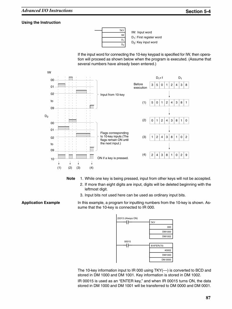
87
Using the Instruction
TKY
IW
D1
D2
IW: Input word
D1: First register word
D2: Key input word
If the input word for connecting the 10-key keypad is specified for IW, then opera-tion will proceed as shown below when the program is executed. (Assume thatseveral numbers have already been entered.)
3 5 0 1 2 4 3 8
5 0 1 2 4 3 8 1
0 1 2 4 3 8 1 0
1 2 4 3 8 1 0 2
2 4 3 8 1 0 2 9
D1+1 D1
(1)
(2)
(3)
(4)
(1) (2) (3) (4)
00
01
02
09
00
01
02
09
10
to
IW
to
Input from 10-key
Flags correspondingto 10-key inputs (Theflags remain ON untilthe next input.)
ON if a key is pressed.
D2
Beforeexecution
Note 1. While one key is being pressed, input from other keys will not be accepted.
2. If more than eight digits are input, digits will be deleted beginning with theleftmost digit.
3. Input bits not used here can be used as ordinary input bits.
Application Example In this example, a program for inputting numbers from the 10-key is shown. As-sume that the 10-key is connected to IR 000.
TKY
000
DM1000
DM1002
25313 (Always ON)
@XFER(70)
#0002
DM1000
DM 0000
00015
The 10-key information input to IR 000 using TKY(––) is converted to BCD andstored in DM 1000 and DM 1001. Key information is stored in DM 1002.
IR 00015 is used as an “ENTER key,” and when IR 00015 turns ON, the datastored in DM 1000 and DM 1001 will be transferred to DM 0000 and DM 0001.
Advanced I/O Instructions Section 5-4
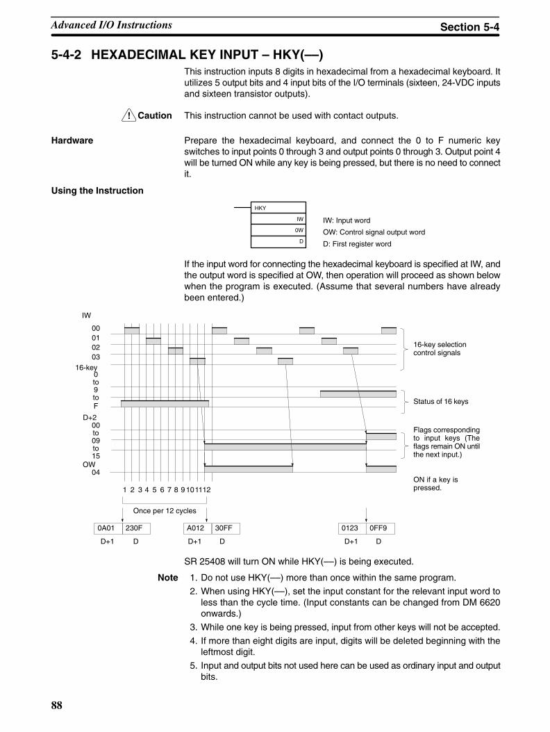
!
88
5-4-2 HEXADECIMAL KEY INPUT – HKY(––)This instruction inputs 8 digits in hexadecimal from a hexadecimal keyboard. Itutilizes 5 output bits and 4 input bits of the I/O terminals (sixteen, 24-VDC inputsand sixteen transistor outputs).
Caution This instruction cannot be used with contact outputs.
Hardware Prepare the hexadecimal keyboard, and connect the 0 to F numeric keyswitches to input points 0 through 3 and output points 0 through 3. Output point 4will be turned ON while any key is being pressed, but there is no need to connectit.
Using the Instruction
HKY
IW
0W
D
IW: Input word
OW: Control signal output word
D: First register word
If the input word for connecting the hexadecimal keyboard is specified at IW, andthe output word is specified at OW, then operation will proceed as shown belowwhen the program is executed. (Assume that several numbers have alreadybeen entered.)
230F
1 2 3 4 5 6 7 8
0A01
D+1 D
A012
D+1
30FF
D
9101112
0123
D+1
0FF9
D
IW
16-key0to9to
D+200to09to15
OW04
F
00010203
Once per 12 cycles
16-key selectioncontrol signals
Status of 16 keys
Flags correspondingto input keys (Theflags remain ON untilthe next input.)
ON if a key ispressed.
SR 25408 will turn ON while HKY(––) is being executed.
Note 1. Do not use HKY(––) more than once within the same program.
2. When using HKY(––), set the input constant for the relevant input word toless than the cycle time. (Input constants can be changed from DM 6620onwards.)
3. While one key is being pressed, input from other keys will not be accepted.
4. If more than eight digits are input, digits will be deleted beginning with theleftmost digit.
5. Input and output bits not used here can be used as ordinary input and outputbits.
Advanced I/O Instructions Section 5-4

!
89
With this instruction, one key input is read in 3 to 12 cycles. More than one cycleis required because the ON keys can only be determined as the outputs areturned ON to test them.
Application Example This example shows a program for inputting numbers from a hexadecimal key-board. Assume that the hexadecimal keyboard is connected to IR 000 (input)and IR 100 (output).
HKY
000
100
DM1000
@XFER(70)
#0002
DM1000
DM0000
00015
25313 (Always ON)
The hexadecimal key information that is input to IR 000 by HKY(––) is convertedto hexadecimal and stored in words DM1000 and DM1001.
IR 00015 is used as an “ENTER key,” and when IR 00015 turns ON, the numbersstored in DM 1000 and DM 1001 are transferred to DM 0000 and DM 0001.
5-4-3 DIGITAL SWITCH INPUT – DSW(––)With this instruction, 4-digit or 8-digit set values are read from a digital switch.DSW(––) utilizes 5 output bits and either 4 input bits (for 4 digits) or 8 input bits(for 8 digits) of the I/O terminals (sixteen, 24-VDC inputs and sixteen transistoroutputs).
Caution This instruction cannot be used with contact outputs.
Hardware Connect the digital switch (e.g., A7E) or thumbwheel switch (e.g., A7B) and I/Oterminals. When using a 4-digit input, connect D0 through D3 from the digitalswitch (least-significant digits) through an interface to input points 0 through 3.When using a 8-digit input, connect D0 through D7 from the digital switchthrough an interface to input points 0 through 7. The output terminals 0 to 4 areconnected to the CS, RD, and similar terminals. In either case, output point 5 willbe turned ON when one round of data is read, but there is no need to connectoutput point 5 unless required for the application.
Preparations When using DSW(––), make the following setting in the ID Controller Setup inPROGRAM mode before executing the program.
Digital Switch Settings (ID Controller Setup)
15 0
– –Bit
DM6639
Number of digits to read00: 4 digits01: 8 digits
Default: 4 digits
Do not make any changes to bits 0 to 7. They are not related to DSW(––).
Advanced I/O Instructions Section 5-4

90
Using the Instruction
DSW
IW
OW
R
IW: Input wordOW: Output wordR: First register word
If the input word for connecting the digital switch is specified at for IW, and theoutput word is specified for OW, then operation will proceed as shown belowwhen the program is executed.
00
01
02
03
04
05
Wd 0
100 101 102 103
D+1 D
Four digits: 00 to 03
Eight digits: 00 to 03, 04 to 07
1 2 3 4 5 6 7 8 9 10 11 12 13 14 15 16
IW
When only 4 digits are read,only word D is used.
Leftmost4 digits
Rightmost4 digits
16 cycles to complete one round of execution
Input data
CS signal
1 Round Flag
RD (read) signal
SR 25410 will turn ON while DSW(––) is being executed.
Note 1. Do not use DSW(––) more than once within the same program.
2. When using DSW(––), set the input constant for the relevant input word toless than the cycle time. (Input constants can be changed from DM 6620onwards.) The characteristics of the digital switch must also be consideredin system and program design.
3. Input and output bits not used here can be used as ordinary input and outputbits.
With this instruction, 4-digit or 8-digit set values can be read in 16 cycles.
Advanced I/O Instructions Section 5-4
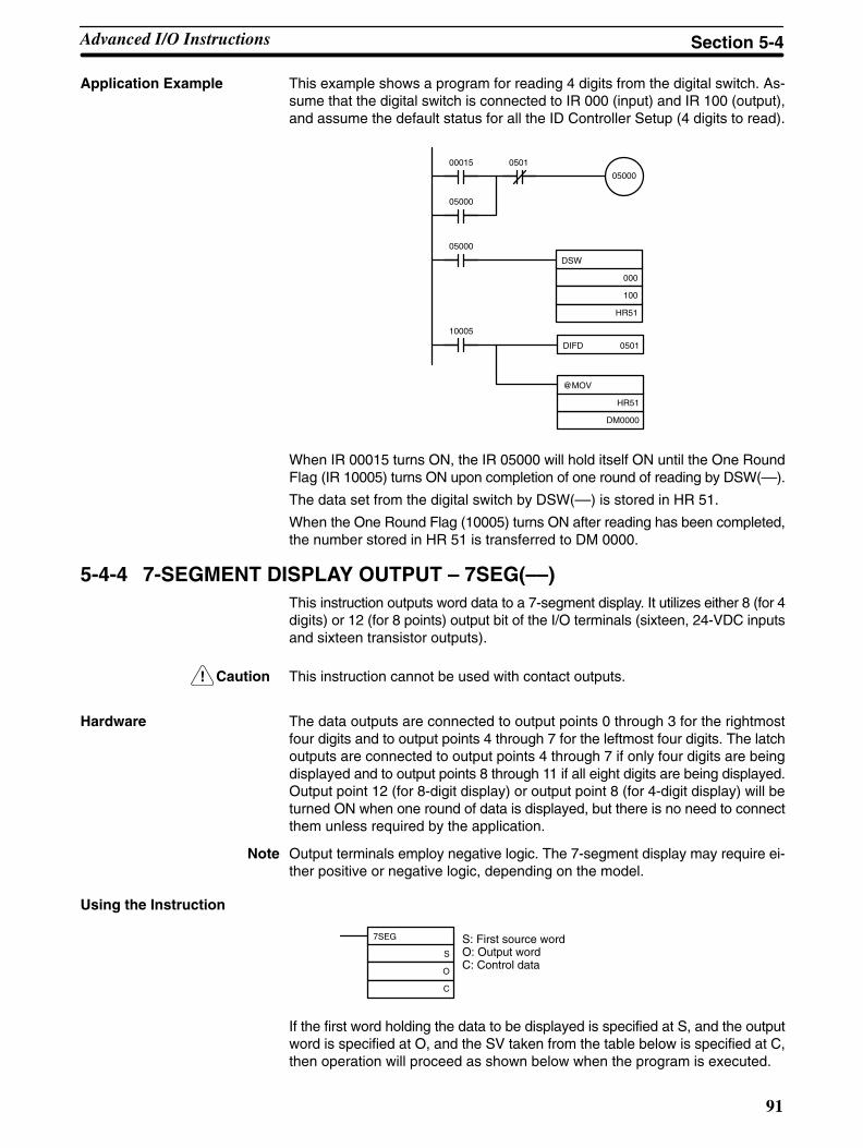
!
91
Application Example This example shows a program for reading 4 digits from the digital switch. As-sume that the digital switch is connected to IR 000 (input) and IR 100 (output),and assume the default status for all the ID Controller Setup (4 digits to read).
DIFD 0501
DSW
000
100
HR51
05000
00015 0501
05000
05000
10005
@MOV
HR51
DM0000
When IR 00015 turns ON, the IR 05000 will hold itself ON until the One RoundFlag (IR 10005) turns ON upon completion of one round of reading by DSW(––).
The data set from the digital switch by DSW(––) is stored in HR 51.
When the One Round Flag (10005) turns ON after reading has been completed,the number stored in HR 51 is transferred to DM 0000.
5-4-4 7-SEGMENT DISPLAY OUTPUT – 7SEG(––)This instruction outputs word data to a 7-segment display. It utilizes either 8 (for 4digits) or 12 (for 8 points) output bit of the I/O terminals (sixteen, 24-VDC inputsand sixteen transistor outputs).
Caution This instruction cannot be used with contact outputs.
Hardware The data outputs are connected to output points 0 through 3 for the rightmostfour digits and to output points 4 through 7 for the leftmost four digits. The latchoutputs are connected to output points 4 through 7 if only four digits are beingdisplayed and to output points 8 through 11 if all eight digits are being displayed.Output point 12 (for 8-digit display) or output point 8 (for 4-digit display) will beturned ON when one round of data is displayed, but there is no need to connectthem unless required by the application.
Note Output terminals employ negative logic. The 7-segment display may require ei-ther positive or negative logic, depending on the model.
Using the Instruction
7SEG
S
O
C
S: First source wordO: Output wordC: Control data
If the first word holding the data to be displayed is specified at S, and the outputword is specified at O, and the SV taken from the table below is specified at C,then operation will proceed as shown below when the program is executed.
Advanced I/O Instructions Section 5-4

92
Data Storage Format
Leftmost 4 digits Rightmost 4 digits
S+1 S
If only four digits are displayed, then only word S will be used.
Set Values for Selecting Logic and Number of Digits (C)
Number of digits displayed Display Unit data input andoutput logic
Display Unit latch input andoutput logic
C setting data
4 digits (4 digits, 1 block) Same Same 000g ( g , )
Different 001
Different Same 002
Different 003
8 digits (4 digits, 2 blocks) Same Same 004g ( g , )
Different 005
Different Same 006
Different 007
Note Do not set C to values other than 000 to 007.
Function Bit(s) in O Output status (Data and latch logic depends on C)
(4 digits,1 block)
(4 digits,2 blocks)
p ( g p )
Latch output 2
Latch output 3
One Round Flag
Latch output 1
Latch output 0
Data output
06
07
08
05
04
00 to 03
10
11
12
09
08
00 to 0304 to 07
100 101 102 103
1 2 3 4 5 6 7 8 9 10 11 12 1
Note 0 to 3: Data output for word S4 to 7: Data output for word S+1
12 cycles required to complete one round
SR 25409 will turn ON while 7SEG(––) is being executed.
Note 1. Do not use 7SEG(––) more than once within the same program.
2. Consider the cycle time and the characteristics of the 7-segment displaywhen designing the system.
3. Output bits not used here can be used as ordinary output bits.
With this instruction, 4 digits or 8 digits are displayed in 12 cycles.
Operation will proceed from the first execution without regard to the status priorto execution.
Advanced I/O Instructions Section 5-4

93
Application Example This example shows a program for displaying the ID Controller’s 8-digit BCDnumbers at the 7-segment LED display. Assume that the 7-segment display isconnected to output word IR 100. Also assume that the output is using negativelogic, and that the 7-segment display logic is also negative for data signals andlatch signals.
7SEG
DM0120
100
004
25313 (Always ON)
The 8-digit data in DM 0120 (rightmost 4 digits) and DM 0121 (leftmost 4 digits)are always displayed by means of 7SEG(––). When the contents of DM 0120and DM 0121 change, the display will also change.
5-4-5 Alternate I/O Bits
Although the advanced I/O instructions generally using I/O bits starting from bit00 of the specified words, they can be programmed through intermediate wordsto use other I/O bits. The following example shows how this can be achieved forHKY(––). Refer to the CQM1 Programming Manual for further details.
Example The following wiring and program examples show how to use input bits IR 00004through IR 00007 and output bits IR 10004 through IR 10007 to input values froma hexadecimal keypad.
Program
HKY
DM0000
DM0100
DM1000
MOVD (83)
DM0100
#0100
100
MOVD(83)
000
#0001
DM0000
25313 (Always ON)
Bits 04 through 07 of IR 000 aretransferred to bits 00 through 03 ofDM 0000.
HKY execution
DM 0100
015015
IR 000
DM 0000 IR 100Input
Output
HKY is coded using DM 0000 as theinput word and DM 0100 as theoutput word. Execution results areplaced in DM 1000 to DM 1002.
Bits 00 through 03 of DM 0100 aretransferred to bits 04 through 07 ofIR 100.
Advanced I/O Instructions Section 5-4
94
5-5 Using InterruptsThis section explains the settings and methods for using the ID Controller’s in-terrupt functions.
5-5-1 Types of Interrupts
The ID Controller has four types of interrupt processing, as outlined below.
ID Communications Response Interrupts:Interrupt processing is executed as required to process ID communications.
Input interrupts:Interrupt processing is executed when an input from an external source turnsON one of ID Controller bits 00000 to 00003.
Interval timer interrupts:Interrupt processing is executed by an interval timer with a precision of 0.1 ms.
High-speed counter interrupts:Interrupt processing is executed according to the present value (PV) of a built-inhigh-speed counter. All ID Controllers are equipped with a high-speed counter,which counts pulse inputs to one of ID Controller bits 00004 to 00006. Two-phase pulses up to 2.5 kHz can be counted.
Interrupt Processing When an interrupt is generated, the specified interrupt processing routine isexecuted. Interrupts have the following priority ranking.
1, 2, 3... 1. Input interrupt 0 > Input interrupt 1 > Input interrupt 2 > Input interrupt 3
2. ID communications response interrupt
3. High-speed counter interrupt
4. Interval timer interrupt 0 > Interval timer interrupt 1 > Interval timer interrupt 2(Interval timer interrupt 2 = high-speed counter interrupt)
When an interrupt with a higher priority is received during interrupt processing,the current processes will be stopped and the newly received interrupt will beprocessed instead. After that routine has been completely executed, then pro-cessing of the previous interrupt will be resumed.
When an interrupt with a lower or equal priority is received during interrupt pro-cessing, then the newly received interrupt will be processed as soon as the rou-tine currently being processed has been completely executed.
Just as with ordinary subroutines, interrupt processing routines are defined us-ing SBN(92) and RET(93) at the end of the main program.
When interrupt processing routines are executed, a specified range of input bitscan be refreshed.
When an interrupt processing routine is defined, a “no SBS error” will be gener-ated during the program check but execution will proceed normally. If this erroroccurs, check all normal subroutines to be sure that SBS(91) has been pro-grammed before proceeding.
The following instructions will not be executed in an interrupt subroutine when aninstruction that controls pulse I/O or high-speed counters is being executed inthe main program: (SR 25503 will turn ON)
INI(––), PRV(––), CTBL(––), SPED(––), PULS(––)
Pulse Output Instructionsand Interrupts
Using Interrupts Section 5-5
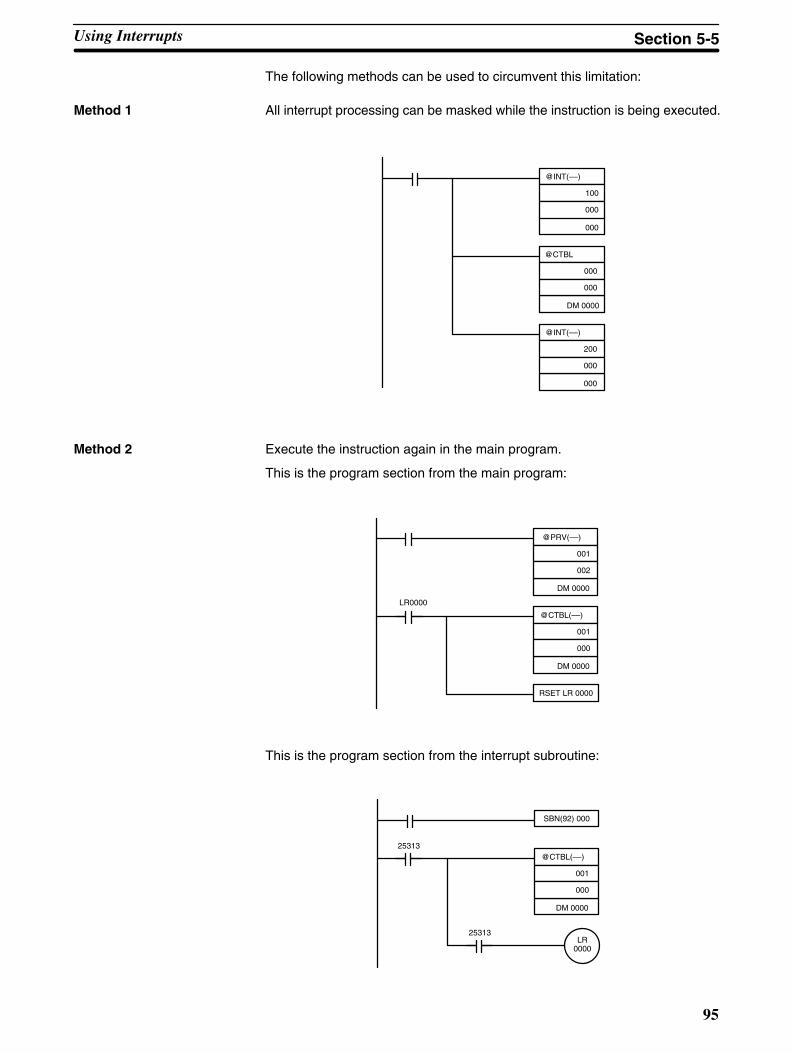
95
The following methods can be used to circumvent this limitation:
Method 1 All interrupt processing can be masked while the instruction is being executed.
@INT(––)
000
100
000
@CTBL
000
000
DM 0000
@INT(––)
000
200
000
Method 2 Execute the instruction again in the main program.
This is the program section from the main program:
@PRV(––)
002
001
DM 0000
@CTBL(––)
000
001
DM 0000
RSET LR 0000
LR0000
This is the program section from the interrupt subroutine:
SBN(92) 000
@CTBL(––)
000
001
DM 0000
25313
25313LR
0000
Using Interrupts Section 5-5

96
5-5-2 ID Communications Response InterruptsRefreshing interrupts for ID communications responses can be specified inbits 04 to 07 of DM 6611 of the ID Controller Setup to enable the generation ofinterrupts to process ID communications. Subroutines 004 through 009 areused to process ID communications, with the specific subroutine depending onthe instruction that is executed as shown below.
Instruction Subroutineexecuted
IDRD(61): 004
IDWT(62): 005
IDAR(63): 006
IDAW(64): 007
IDCA(65): 008
IDMD(66): 009
Using ID communications response interrupts will increase the speed of com-munications with Data Carriers and will enable executing the appropriate pro-gramming (i.e., subroutine) as soon as Data Carrier communications end. Thiswill allow you to process data from Data Carriers immediately using ladder-dia-gram programming and then write the results back to the Data Carriers withoutbeing affected by the scan time of the ID Controller.
ID Controller Setup To execute subroutines upon completion of ID communications, set the ID com-munications response refresh method in bit 04 to 07 of DM 6611 to “1.” This set-ting must be made with the ID Controller in PROGRAM mode before the pro-gram is executed. If you do not make this setting, interrupts will not be generatedat the completion of ID communications and execution results will be refreshedonly once each scan.
ID communications response interrupts0: No interrupts1: Interrupts enabled
Default: No interrupts
15 0
DM 6611
Bit
Note Subroutines 004 through 009 can be used as normal subroutines if ID commu-nications response interrupts are not being used.
5-5-3 Input InterruptsThe ID Controller’s inputs allocated IR 00000 to IR 00003 can be used for inter-rupts from external sources. Input interrupts 0 through 3 correspond respective-ly to these bits and are always used to call the subroutines numbered 000through 003 respectively. When input interrupts are not used, subroutine num-bers 000 to 003 can be used for ordinary subroutines.
Processing There are two modes for processing input interrupts.The first is the Input Interrupt Mode, in which the interrupt is carried out in re-sponse to an external input. In the Input Interrupt Mode, signals with a length of100 s or more can be detected.The second is the Counter Mode, in which signals from an external source arecounted at high speed, and an interrupt is carried out once for every certain num-ber of signals. In the Counter Mode, signals up to 1 kHz can be counted.
Using Interrupts Section 5-5

97
ID Controller Setup Before executing the program, make the following settings in the ID ControllerSetup in PROGRAM mode.
Interrupt Input Settings (DM 6628)
If these settings are not made, interrupts cannot be used in the program.
Input interrupt 3 setting
Input interrupt 2 setting
Input interrupt 1 setting
Input interrupt 0 setting0: Normal input1: Interrupt input
Default: All normal inputs.
15 0
DM6628
Bit
Input Refresh Word Settings (DM 6630 to DM 6633)
Make these settings when it is necessary to refresh inputs.
Input refresh setting 00 or 01
Set to 00
Default: No input refresh
15 0
DM6630 to DM 6633
Bit
DM 6630: Interrupt 0DM 6631: Interrupt 1DM 6632: Interrupt 2DM 6633: Interrupt 3
Example: If DM 6630 is set to 0100, IR 000 will be refreshed when a signal isreceived for interrupt 0.
Note If input refreshing is not used, input signal status within the interrupt routine willnot be turned ON during execution of the routine. This includes even the statusof the interrupt input bit that activated the interrupt. For example, IR 00000 wouldnot be ON in interrupt routine for input interrupt 0 unless it was refreshed (in thiscase, the Always ON Flag, SR 25313 could be used in place of IR 00000).
Input Interrupt Mode Use the following instructions to program input interrupts using the Input Inter-rupt Mode.
Masking of Interrupts
With the INT(––) instruction, set or clear input interrupt masks as required.
(@)INT
000
000
D
Make the settings with the D bits 0 to 3, which correspond toinput interrupts 0 to 3.
0: Mask cleared. (Input interrupt permitted.)1: Mask set. (Input interrupt not permitted.)
At the beginning of operation, all of the input interrupts are masked and must beunmasked (cleared) to be used.
Clearing Masked Interrupts
If the bit corresponding to an input interrupt turns ON while masked, that inputinterrupt will be saved in memory and will be executed as soon as the mask iscleared. In order for that input interrupt not to be executed when the mask iscleared, the interrupt must be cleared from memory.
Using Interrupts Section 5-5
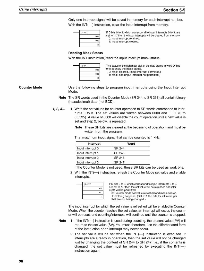
98
Only one interrupt signal will be saved in memory for each interrupt number.
With the INT(––) instruction, clear the input interrupt from memory.
(@)INT
001
000
D
If D bits 0 to 3, which correspond to input interrupts 0 to 3, areset to “1,” then the input interrupts will be cleared from memory.
0: Input interrupt retained.1: Input interrupt cleared.
Reading Mask StatusWith the INT instruction, read the input interrupt mask status.
(@)INT
002
000
D
The status of the rightmost digit of the data stored in word D (bits0 to 3) show the mask status.
0: Mask cleared. (Input interrupt permitted.)1: Mask set. (Input interrupt not permitted.)
Counter Mode Use the following steps to program input interrupts using the Input InterruptMode.
Note The SR words used in the Counter Mode (SR 244 to SR 251) all contain binary(hexadecimal) data (not BCD).
1, 2, 3... 1. Write the set values for counter operation to SR words correspond to inter-rupts 0 to 3. The set values are written between 0000 and FFFF (0 to65,535). A value of 0000 will disable the count operation until a new value isset and step 2, below, is repeated.
Note These SR bits are cleared at the beginning of operation, and must bewritten from the program.
That maximum input signal that can be counted is 1 kHz.
Interrupt Word
Input interrupt 0 SR 244
Input interrupt 1 SR 245
Input interrupt 2 SR 246
Input interrupt 3 SR 247
If the Counter Mode is not used, these SR bits can be used as work bits.
2. With the INT(––) instruction, refresh the Counter Mode set value and enableinterrupts.
(@)INT
003
000
D
If D bits 0 to 3, which correspond to input interrupts 0 to 3,are set to “0,” then the set value will be refreshed and inter-rupts will be permitted.
0: Counter mode set value refreshed and mask cleared.1: Nothing happens. (Set to 1 the bits for all interruptsthat are not being changed.)
The input interrupt for which the set value is refreshed will be enabled in CounterMode. When the counter reaches the set value, an interrupt will occur, the count-er will be reset, and counting/interrupts will continue until the counter is stopped.
Note 1. If the INT(––) instruction is used during counting, the present value (PV) willreturn to the set value (SV). You must, therefore, use the differentiated formof the instruction or an interrupt may never occur.
2. The set value will be set when the INT(––) instruction is executed. Ifinterrupts are already in operation, then the set value will not be changedjust by changing the content of SR 244 to SR 247, i.e., if the contents ischanged, the set value must be refreshed by executing the INT(––)instruction again.
Using Interrupts Section 5-5
99
Interrupts can be masked using the same process as for the Input InterruptMode, but is masked are cleared using the same process, the Counter Mode willnot be maintained and the Input Interrupt Mode will be used instead. Interruptsignals received for masked interrupts can also be cleared using the same pro-cess as for the Input Interrupt Mode.
Counter PV in Counter ModeWhen input interrupts are used in Counter Mode, the counter PV will be stored inthe SR word corresponding to input interrupts 0 to 3. Values are 0000 to FFFE (0to 65,534) and will equal the counter PV minus one.
Interrupt Word
Input interrupt 0 SR 248
Input interrupt 1 SR 249
Input interrupt 2 SR 250
Input interrupt 3 SR 251
Example: The present value for an interrupt whose set value is 000A will be re-corded as 0009 immediately after INT(––) is executed.
Note Even if input interrupts are not used in Counter Mode, these SR bits cannot beused as work bits.
Application Example In this example, input interrupt 0 is used in Input Interrupt Mode and input inter-rupt 1 is used in Counter Mode. Before executing the program, check to be surethe ID Controller Setup.
Using Interrupts Section 5-5

100
ID Controller Setup: DM 6628: 0011 (IR 00000 and IR 00001 used for input inter-rupts) The default settings are used for all other ID Controller Setup parameters.(Inputs are not refreshed at the time of interrupt processing.)
SBN(92) 000
00100
MOV(21)
#000A
245
25315 (ON for 1 scan)
(@)INT
001
000
#0003
(@)INT
000
000
#000E
(@)INT
003
000
#000D
(@)INT
000
000
#000F
00100
25313 (Always ON)
ADB(50)
245
#000A
245
INT
003
000
#000D
RET(93)
SBN(92) 001
RET(93)
BCD (24)
249
D0000
INC(38)
D0000
Sets 10 as the counter mode SV for input interrupt 1.
When IR 00100 turns ON:Masked interrupts for input interrupts 0 and 1 are cleared.
Interrupts are enabled in input interrupt mode for interrupt 0.
Interrupts are enabled in counter mode for interrupt 1.(SV: 10 )
When IR 00100 turns OFF, input interrupts 0 and 1 aremasked and interrupts are prohibited.
When the Input interrupt is executed for interrupt 0, sub-routine 000 is called and the counter mode is refreshedwith the SV for input interrupt 1 with 10 added (SV = 20)
When the count is reached for the input interrupt 1counter, subroutine 001 is called and the interrupt pro-cessing routine is executed.
The contents of SR 249 (PV – 1) are converted to BCDand stored in DM 0000.
The content to DM 0000 is incremented to the IDController.
Using Interrupts Section 5-5
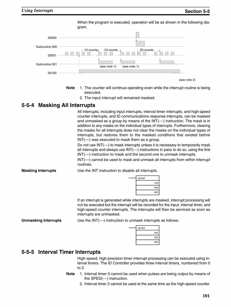
101
When the program is executed, operation will be as shown in the following dia-gram.
00000
00001
00100
Subroutine 000
Subroutine 001(see note 1) (see note 1)
(see note 2)
10 counts 10 counts 20 counts
Note 1. The counter will continue operating even while the interrupt routine is beingexecuted.
2. The input interrupt will remained masked.
5-5-4 Masking All InterruptsAll interrupts, including input interrupts, interval timer interrupts, and high-speedcounter interrupts, and ID communications response interrupts, can be maskedand unmasked as a group by means of the INT(––) instruction. The mask is inaddition to any masks on the individual types of interrupts. Furthermore, clearingthe masks for all interrupts does not clear the masks on the individual types ofinterrupts, but restores them to the masked conditions that existed beforeINT(––) was executed to mask them as a group.Do not use INT(––) to mask interrupts unless it is necessary to temporarily maskall interrupts and always use INT(––) instructions in pairs to do so, using the firstINT(––) instruction to mask and the second one to unmask interrupts.INT(––) cannot be used to mask and unmask all interrupts from within interruptroutines.
Masking Interrupts Use the INT instruction to disable all interrupts.
(@)INT
100
000
000
If an interrupt is generated while interrupts are masked, interrupt processing willnot be executed but the interrupt will be recorded for the input, interval timer, andhigh-speed counter interrupts. The interrupts will then be serviced as soon asinterrupts are unmasked.
Unmasking Interrupts Use the INT(––) instruction to unmask interrupts as follows:
(@)INT
200
000
000
5-5-5 Interval Timer InterruptsHigh-speed, high-precision timer interrupt processing can be executed using in-terval timers. The ID Controller provides three interval timers, numbered from 0to 2.
Note 1. Interval timer 0 cannot be used when pulses are being output by means ofthe SPED(––) instruction.
2. Interval timer 2 cannot be used at the same time as the high-speed counter.
Using Interrupts Section 5-5

102
Processing There are two modes for interval timer operation, the One-shot Mode, in whichonly one interrupt will be executed when time expires, and the Scheduled Inter-rupt Mode, in which the interrupt is repeated at a fixed interval.
ID Controller Setup When using interval timer interrupts, make the following settings in the ID Con-troller Setup in PROGRAM mode before executing the program.
Input Refresh Word Settings (DM 6636 to DM 6638)
Make these settings when it is necessary to refresh inputs.
15 0
DM6636 to DM 6638
Bit
Input refresh setting (2 digits BCD)00 or 01
Set to 00
Default: No input refresh
DM 6636: Timer 0DM 6637: Timer 1DM 6638: Timer 2
High-speed Counter Settings (DM 6642)
When using interval timer 2, check before beginning operation to be sure that thehigh-speed counter (ID Controller Setup: DM 6642) is set to the default setting(0000: High-speed counter not used).
Operation Use the following instruction to activate and control the interval timer.
Starting Up in One-Shot Mode
Use the STIM(––) instruction to start the interval timer in the one-shot mode.
(@)STIM
C1
C2
C3
C1: Interval timer no.Interval timer 0: 000Interval timer 1: 001Interval timer 2: 002
C2: Timer set value (first word address)
C3: Subroutine no. (4 digits BCD): 0000 to 0127
C2: Decrementing counter set value (4 digits BCD): 0000 to 9999C2 + 1: Decrementing time interval (4 digits BCD; unit: 0.1 ms): 0005 to 0320(0.5 ms to 32 ms)
Each time that the interval specified in word C2 + 1 elapses, the decrementingcounter will decrement the present value by one. When the PV reaches 0, thedesignated subroutine will be called just once and the timer will stop.
The time from when the STIM instruction is executed until time elapses is calcu-lated as follows:(Contents of word C2) x (Contents of word C2 + 1) x 0.1 ms = (0.5 to 319,968 ms)
If a constant is set for C2, then the set value of the decrementing counter will takethat value and the decrementing time interval will be 10 (1 ms). (The set value isexpressed in ms.)
Using Interrupts Section 5-5

103
Starting Up in Scheduled Interrupt Mode
Use the STIM(––) instruction to start the interval timer in the scheduled interruptmode.
(@)STIM
C1
C2
C3
C1: Interval timer no.Interval timer 0: 003Interval timer 1: 004Interval timer 2: 005
C2: Timer set value (leading word no.)
C3: Subroutine no. (4 digits BCD): 0000 to 0127
C2: Decrementing counter set value (4 digits BCD): 0000 to 9999C2 + 1: Decrementing time interval (4 digits BCD; unit: 0.1 ms): 0005 to 0320(0.5 ms to 32 ms)
The meanings of the settings are the same as for the one-shot mode, but in thescheduled interrupt mode the timer PV will be reset to the set value and decre-menting will begin again after the subroutine has been called. In the scheduledinterrupt mode, interrupts will continue to be repeated at fixed intervals until theoperation is stopped.
Reading the Timer’s Elapsed Time
Use the STIM(––) instruction to read the timer’s elapsed time.
(@)STIM
C1
C2
C3
C1: Interval timer no.Interval timer 0: 006Interval timer 1: 007Interval timer 2: 008
C2: Leading word of parameter 1
C3: Parameter 2
C2: Number of times counter has been decremented (4 digits BCD)C2 + 1: Decrementing counter time interval (4 digits BCD; unit: 0.1 ms)C3: Time since previous decrement (4 digits BCD; unit: 0.1 ms)
The time from when the interval timer is started until the execution of this instruc-tion is calculated as follows:
(Contents of word C2) x (Contents of word C2 + 1) + (Contents of word C3) x 0.1 ms
If the specified interval timer is stopped, then “0000” will be stored.
Stopping Timers
Use the STIM(––) instruction to stop the interval timer.
(@)STIM
C1
000
000
C1: Interval timer no.Interval timer 0: 010Interval timer 1: 011Interval timer 2: 012
The specified interval timer will stop.
Using Interrupts Section 5-5
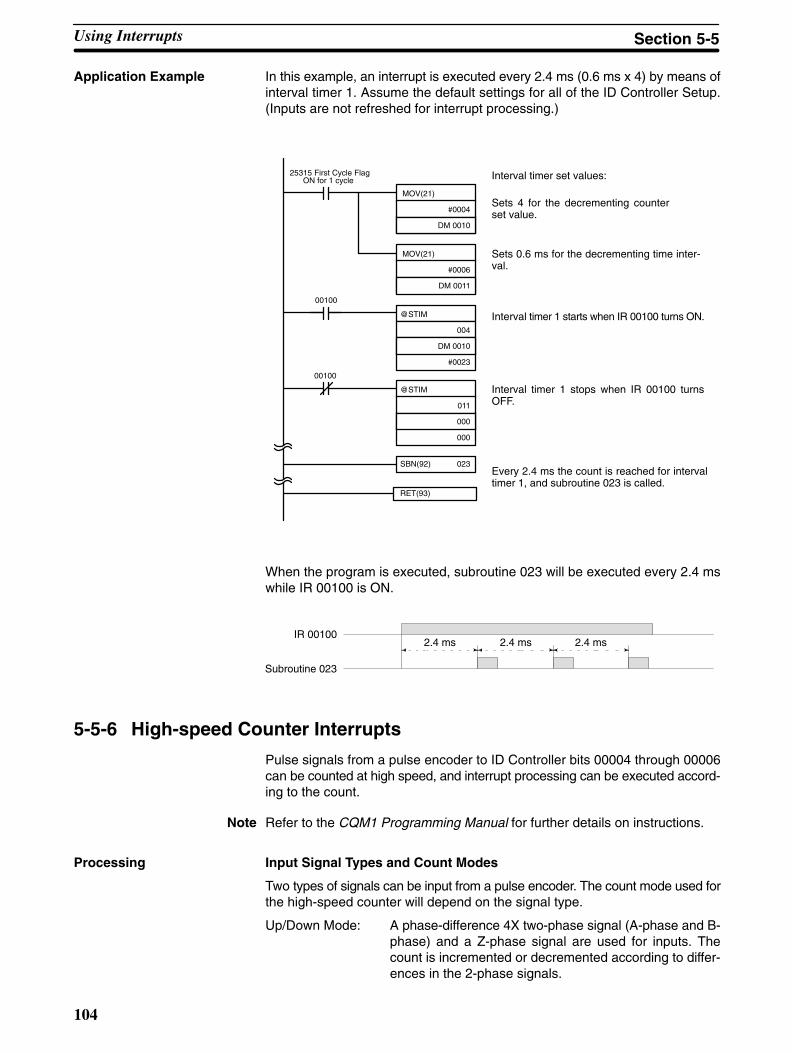
104
Application Example In this example, an interrupt is executed every 2.4 ms (0.6 ms x 4) by means ofinterval timer 1. Assume the default settings for all of the ID Controller Setup.(Inputs are not refreshed for interrupt processing.)
MOV(21)
#0004
DM 0010
MOV(21)
#0006
DM 0011
SBN(92) 023
RET(93)
@STIM
004
DM 0010
#0023
@STIM
011
000
000
00100
00100
Every 2.4 ms the count is reached for intervaltimer 1, and subroutine 023 is called.
Interval timer set values:
Sets 4 for the decrementing counterset value.
Sets 0.6 ms for the decrementing time inter-val.
Interval timer 1 starts when IR 00100 turns ON.
Interval timer 1 stops when IR 00100 turnsOFF.
25315 First Cycle FlagON for 1 cycle
When the program is executed, subroutine 023 will be executed every 2.4 mswhile IR 00100 is ON.
IR 00100
Subroutine 023
2.4 ms 2.4 ms 2.4 ms
5-5-6 High-speed Counter Interrupts
Pulse signals from a pulse encoder to ID Controller bits 00004 through 00006can be counted at high speed, and interrupt processing can be executed accord-ing to the count.
Note Refer to the CQM1 Programming Manual for further details on instructions.
Processing Input Signal Types and Count Modes
Two types of signals can be input from a pulse encoder. The count mode used forthe high-speed counter will depend on the signal type.
Up/Down Mode: A phase-difference 4X two-phase signal (A-phase and B-phase) and a Z-phase signal are used for inputs. Thecount is incremented or decremented according to differ-ences in the 2-phase signals.
Using Interrupts Section 5-5
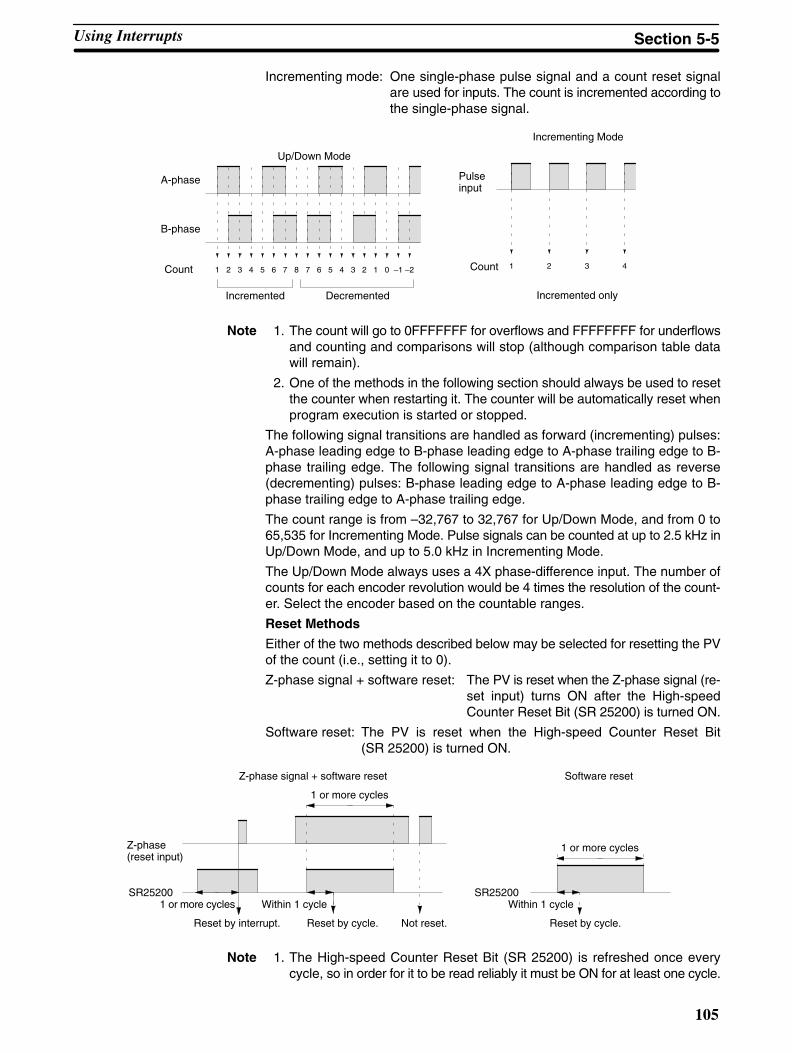
105
Incrementing mode: One single-phase pulse signal and a count reset signalare used for inputs. The count is incremented according tothe single-phase signal.
1 2 3 4 5 6 7 8 7 6 5 4 3 2 1 0 –1 –2 1 2 3 4
A-phase
B-phase
Up/Down Mode
Count
Incremented Decremented
Count
Pulse input
Incrementing Mode
Incremented only
Note 1. The count will go to 0FFFFFFF for overflows and FFFFFFFF for underflowsand counting and comparisons will stop (although comparison table datawill remain).
2. One of the methods in the following section should always be used to resetthe counter when restarting it. The counter will be automatically reset whenprogram execution is started or stopped.
The following signal transitions are handled as forward (incrementing) pulses:A-phase leading edge to B-phase leading edge to A-phase trailing edge to B-phase trailing edge. The following signal transitions are handled as reverse(decrementing) pulses: B-phase leading edge to A-phase leading edge to B-phase trailing edge to A-phase trailing edge.
The count range is from –32,767 to 32,767 for Up/Down Mode, and from 0 to65,535 for Incrementing Mode. Pulse signals can be counted at up to 2.5 kHz inUp/Down Mode, and up to 5.0 kHz in Incrementing Mode.
The Up/Down Mode always uses a 4X phase-difference input. The number ofcounts for each encoder revolution would be 4 times the resolution of the count-er. Select the encoder based on the countable ranges.
Reset Methods
Either of the two methods described below may be selected for resetting the PVof the count (i.e., setting it to 0).
Z-phase signal + software reset: The PV is reset when the Z-phase signal (re-set input) turns ON after the High-speedCounter Reset Bit (SR 25200) is turned ON.
Software reset: The PV is reset when the High-speed Counter Reset Bit(SR 25200) is turned ON.
SR25200
Z-phase(reset input)
Z-phase signal + software reset
1 or more cycles
1 or more cycles
Reset by interrupt.
Within 1 cycle
Reset by cycle. Not reset. Reset by cycle.
Within 1 cycle
1 or more cycles
Software reset
SR25200
Note 1. The High-speed Counter Reset Bit (SR 25200) is refreshed once everycycle, so in order for it to be read reliably it must be ON for at least one cycle.
Using Interrupts Section 5-5

106
2. The comparison table, comparison execution status, and range comparisonresults data will be preserved when the counter is reset, allowing executionto continue from the same condition as before being reset.
The “Z” in “Z-phase” is an abbreviation for “Zero.” It is a signal that shows that theencoder has completed one cycle.
High-speed Counter Interrupt Count
For high-speed counter interrupts, a comparison table is used instead of a“count up.” The count check can be carried out by either of the two methods de-scribed below. In the comparison table, comparison conditions (for comparing tothe PV) and interrupt routine combinations are saved.
Target value: A maximum of 16 comparison conditions (targetvalues and count directions) and interrupt routinecombinations are saved in the comparison table.When the counter PV and the count direction matchthe comparison conditions, then the specified inter-rupt routine is executed.
Range comparison: Eight comparison conditions (upper and lower lim-its) and interrupt routine combinations are saved inthe comparison table. When the PV is greater thanor equal to the lower limit and less than or equal tothe upper limit, then the specified interrupt routineis executed.
Wiring Depending on the count mode, the input signals from the pulse encoder to the IDController’s input terminal are as shown below.
Terminal no. Up/Down Mode Incrementing Mode
4 Encoder A-phase Pulse count input
5 Encoder B-phase ---
6 Encoder Z-phase Reset input
If only the software reset is to be used, terminal 6 can be used as an ordinaryinput. When in Incrementing Mode, terminal 5 can be used as an ordinary input.
ID Controller Setup When using high-speed counter interrupts, make the settings in PROGRAMmode shown below before executing the program.
Input Refresh Word Settings (DM 6638)
Make these settings when it is necessary to refresh inputs. The setting is thesame as that for interval timer 2.
15 0
DM6638
Bit
Input refresh setting 00 or 01
Set to 00
Default: No input refresh
Using Interrupts Section 5-5

107
High-speed Counter Settings (DM 6642)
If these settings are not made, the high-speed counter cannot be used in the pro-gram.
High-speed counter used.
15 0
DM6642
Bit
0 1
Reset method0: Z-phase and software reset1: Software reset
Count mode0: Up/Down Mode4: Incrementing Mode
Default: High-speed counter not used.
Changes in the setting in DM 6642 are effective only when power is turned on orID Controller program execution is started.
Programming Use the following steps to program the high-speed counter.
The high-speed counter begins the counting operation when the proper ID Con-troller Setup settings are made, but comparisons will not be made with the com-parison table and interrupts will not be generated unless the CTBL(––) instruc-tion is executed.
The high-speed counter is reset to “0” when power is turned ON, when operationbegins.
The present value of the high-speed counter is maintained in SR 230 andSR 231.
Controlling High-speed Counter Interrupts
1, 2, 3... 1. Use the CTBL(––) instruction to save the comparison table in the ID Control-ler and begin comparisons.
(@)CTBL
000
C
TB
C: (3 digits BCD)000: Target table set and comparison begun001: Range table set and comparison begun002: Target table set only003: Range table set only
TB: Beginning word of comparison table
If C is set to 000, then comparisons will be made by the target matching method;if 001, then they will be made by the range comparison method. The comparisontable will be saved, and, when the save operation is complete, then comparisonswill begin. While comparisons are being executed, high-speed counter inter-rupts will be executed according to the comparison table.
Note The comparison results are stored in AR 1100 through AR 1107 while the rangecomparison is being executed.
If C is set to 002, then comparisons will be made by the target matching method;if 003, then they will be made by the range comparison method. For either ofthese settings, the comparison table will be saved, but comparisons will not be-gin, and the INI(––) instruction must be used to begin comparisons.
Using Interrupts Section 5-5
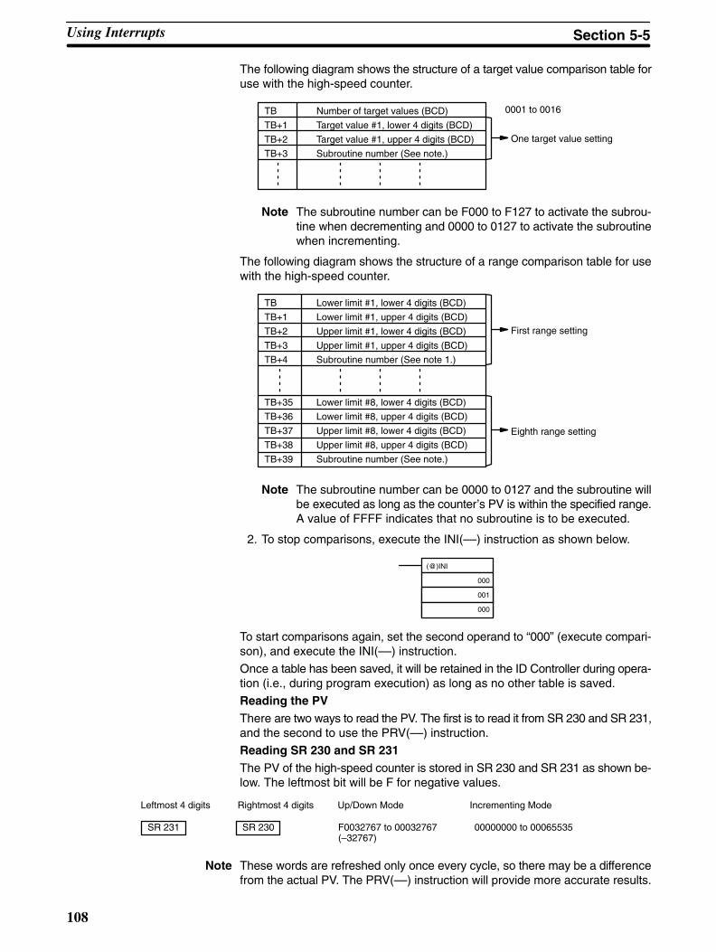
108
The following diagram shows the structure of a target value comparison table foruse with the high-speed counter.
TB Number of target values (BCD)
TB+1 Target value #1, lower 4 digits (BCD)
TB+2 Target value #1, upper 4 digits (BCD)
TB+3 Subroutine number (See note.)
One target value setting
0001 to 0016
Note The subroutine number can be F000 to F127 to activate the subrou-tine when decrementing and 0000 to 0127 to activate the subroutinewhen incrementing.
The following diagram shows the structure of a range comparison table for usewith the high-speed counter.
TB Lower limit #1, lower 4 digits (BCD)
TB+1 Lower limit #1, upper 4 digits (BCD)
TB+2 Upper limit #1, lower 4 digits (BCD)
TB+3 Upper limit #1, upper 4 digits (BCD)
TB+4 Subroutine number (See note 1.)
TB+35 Lower limit #8, lower 4 digits (BCD)
TB+36 Lower limit #8, upper 4 digits (BCD)
TB+37 Upper limit #8, lower 4 digits (BCD)
TB+38 Upper limit #8, upper 4 digits (BCD)
TB+39 Subroutine number (See note.)
First range setting
Eighth range setting
Note The subroutine number can be 0000 to 0127 and the subroutine willbe executed as long as the counter’s PV is within the specified range.A value of FFFF indicates that no subroutine is to be executed.
2. To stop comparisons, execute the INI(––) instruction as shown below.
(@)INI
000
001
000
To start comparisons again, set the second operand to “000” (execute compari-son), and execute the INI(––) instruction.
Once a table has been saved, it will be retained in the ID Controller during opera-tion (i.e., during program execution) as long as no other table is saved.
Reading the PVThere are two ways to read the PV. The first is to read it from SR 230 and SR 231,and the second to use the PRV(––) instruction.
Reading SR 230 and SR 231The PV of the high-speed counter is stored in SR 230 and SR 231 as shown be-low. The leftmost bit will be F for negative values.
Leftmost 4 digits Rightmost 4 digits Up/Down Mode Incrementing Mode
SR 231 SR 230 F0032767 to 00032767(–32767)
00000000 to 00065535
Note These words are refreshed only once every cycle, so there may be a differencefrom the actual PV. The PRV(––) instruction will provide more accurate results.
Using Interrupts Section 5-5

109
When the high-speed counter is not being used, the bits in these words can beused as work bits.
Using the PRV(––) Instruction
Read the PV of the high-speed counter by using the PRV(––) instruction.
(@)PRV
000
000
P1
P1: Leading word of PV
The PV of the high-speed counter is stored as shown below. The leftmost bit willbe F for negative values.
Leftmost 4 digits Rightmost 4 digits Up/Down Mode Incrementing Mode
P1+1 P1 F0032767 to 00032767(–32767)
00000000 to 00065535
The PV is read when the PRV(––) instruction is actually executed.
Changing the PV
There are two ways to change the PV of the high-speed counter. The first way isto reset it by using the reset methods. (In this case the PV is reset to 0.) The se-cond way is to use the INI(––) instruction.
The method using the INI instruction is explained here. For an explanation of thereset method, refer to the beginning of this description of the high-speed count-er.
Change the counter PV by using the INI(––) instruction as shown below.
Leftmost 4 digits Rightmost 4 digits Up/Down Mode Incrementing Mode
D+1 D F0032767 to 00032767 00000000 to 00065535
(@)INI
000
002
D
D: Leading word for storing PV change data
To specify a negative number, set F in the leftmost digit.
Operation Example This example shows a program for using the high-speed counter in the Incre-menting Mode, making comparisons by means of the target matching method,and changing the frequency of pulse outputs according to the counter’s PV. Be-fore executing the program, set the ID Controller Setup as follows:
DM 6642: 0114 (high-speed counter used with software reset and IncrementingMode). For all other ID Controller Setup, use the default settings. (Inputs are notrefreshed at the time of interrupt processing, and pulse outputs are executed forIR 100.)
Using Interrupts Section 5-5
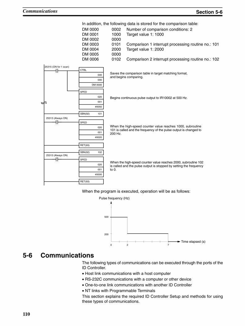
110
In addition, the following data is stored for the comparison table:DM 0000 0002 Number of comparison conditions: 2DM 0001 1000 Target value 1: 1000DM 0002 0000DM 0003 0101 Comparison 1 interrupt processing routine no.: 101DM 0004 2000 Target value 1: 2000DM 0005 0000DM 0006 0102 Comparison 2 interrupt processing routine no.: 102
25315 (ON for 1 scan)
SBN(92) 101
RET(93)
SPED
020
001
#0020
SPED
020
001
#0000
25313 (Always ON)
SBN(92) 102
RET(93)
25313 (Always ON)
CTBL
000
000
DM 0000
SPED
020
001
#0050
Saves the comparison table in target matching format,and begins comparing.
Begins continuous pulse output to IR10002 at 500 Hz.
When the high-speed counter value reaches 1000, subroutine101 is called and the frequency of the pulse output is changed to200 Hz.
When the high-speed counter value reaches 2000, subroutine 102is called and the pulse output is stopped by setting the frequencyto 0.
When the program is executed, operation will be as follows:
0 2 7
200
500
Pulse frequency (Hz)
Time elapsed (s)
5-6 CommunicationsThe following types of communications can be executed through the ports of theID Controller.• Host link communications with a host computer• RS-232C communications with a computer or other device• One-to-one link communications with another ID Controller• NT links with Programmable TerminalsThis section explains the required ID Controller Setup and methods for usingthese types of communications.
Communications Section 5-6

111
5-6-1 ID Controller SetupThe ID Controller Setup parameters in DM 6645 through DM 6654 are used toset parameters for the communications ports. The parameters for the RS-232Cport in DM 6645 through DM 6649 can be set from menu operations using theLSS/SSS.
Note If pin 5 on the ID Controller’s DIP switch is turned ON, the ID Controller Setupcommunications parameters will be ignored and the following parameters will beused.
Mode: Host linkNode number: 00Start bits: 1 bitData length: 7 bitsStop bits: 1 bitParity: EvenBaud rate: 2,400 bpsTransmission delay: None
The settings in DM 6645 and DM 6650 determine the main communications pa-rameters, as shown in the following diagram.
Communications mode0: Host link1: RS-232C2: One-to-one link slave3: One-to-one link master4: NT link
15 0BitDM 6645: RS-232C portDM 6650: Peripheral port
Link words for one-to-one link0: LR 00 to LR 631: LR 00 to LR 312: LR 00 to LR 16
Port settings00: Standard communication conditions01: According to setting in DM 6646, DM 6651
Default: Host link using standard parameters
Note Settings 2 through 4 of the Communications Mode can be used only for theRS-232C port.
5-6-2 Host Link and RS-232C Communications ParametersSelect either host link or RS-232C communications and then set the commu-nications parameters as described next. Match the communications conditionsto the settings at the device with which communications are being carried out.
Standard Communications If the following settings are satisfactory for these communications conditions,then set the two rightmost digits to 00. The settings in DM 6646 and DM 6651 willbe ignored for this setting.
Start bits: 1 bitData length: 7 bitsStop bits: 2 bitsParity: EvenBaud rate: 9,600 bps
Communications Section 5-6
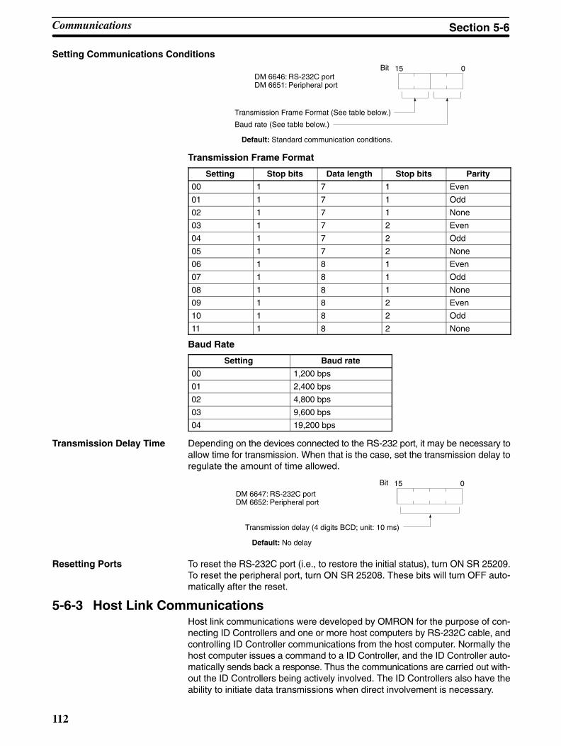
112
Setting Communications Conditions
Transmission Frame Format (See table below.)
Baud rate (See table below.)
Default: Standard communication conditions.
15 0BitDM 6646: RS-232C portDM 6651: Peripheral port
Transmission Frame Format
Setting Stop bits Data length Stop bits Parity
00 1 7 1 Even
01 1 7 1 Odd
02 1 7 1 None
03 1 7 2 Even
04 1 7 2 Odd
05 1 7 2 None
06 1 8 1 Even
07 1 8 1 Odd
08 1 8 1 None
09 1 8 2 Even
10 1 8 2 Odd
11 1 8 2 None
Baud Rate
Setting Baud rate
00 1,200 bps
01 2,400 bps
02 4,800 bps
03 9,600 bps
04 19,200 bps
Transmission Delay Time Depending on the devices connected to the RS-232 port, it may be necessary toallow time for transmission. When that is the case, set the transmission delay toregulate the amount of time allowed.
15 0Bit
Transmission delay (4 digits BCD; unit: 10 ms)
Default: No delay
DM 6647: RS-232C portDM 6652: Peripheral port
Resetting Ports To reset the RS-232C port (i.e., to restore the initial status), turn ON SR 25209.To reset the peripheral port, turn ON SR 25208. These bits will turn OFF auto-matically after the reset.
5-6-3 Host Link CommunicationsHost link communications were developed by OMRON for the purpose of con-necting ID Controllers and one or more host computers by RS-232C cable, andcontrolling ID Controller communications from the host computer. Normally thehost computer issues a command to a ID Controller, and the ID Controller auto-matically sends back a response. Thus the communications are carried out with-out the ID Controllers being actively involved. The ID Controllers also have theability to initiate data transmissions when direct involvement is necessary.
Communications Section 5-6

113
In general, there are two means for implementing host link communications.One is based on C-mode commands, and the other on FINS (CV-mode) com-mands. The ID Controller supports C-mode commands only. For details on hostlink communications, refer to the CQM1 Programming Manual.
Communications Parameters Communications parameters such as the communication conditions, mode,and unit number must be set to use host link communications. Set the ID Con-troller Setup for host link communications (i.e., set bits 12 to 15 of DM 6645 orDM 6650 to zero ) when communicating via host link standards. Always set thesame parameters as the other parties in the communications are using.
Host Link Node Number A node number must be set for host link communications to differentiate be-tween nodes when multiple nodes are participating in communications. This set-ting is required only for host link communications. To use host link communica-tions, the host link must be specified as the communications mode and the com-munications parameters must be set (see following section).
15 0Bit
0 0
Node number (2 digits BCD): 00 to 31
Default: 00
DM 6648: RS-232C portDM 6653: Peripheral port
Set the node number to 00 unless multiple nodes are connected in a network.
Communications Procedure This section explains how to use the host link to execute data transmissions fromthe ID Controller. Using this method enables automatic data transmission fromthe ID Controller when data is changed, and thus simplifies the communicationsprocess by eliminating the need for constant monitoring by the computer.
1, 2, 3... 1. Check to see that AR 0805 (RS-232C Port Transmit Ready Flag) is ON.
2. Use the TXD(––) instruction to transmit the data.
(@)TXD
S
C
N
S: Beginning word no. of transmission data
C: Control dataBits 00 to 11 = 0000Bits 12 to 15
0: RS-232C port1: Peripheral port
N: Number of bytes of data to be sent (4 digits BCD) 0000 to 0061
From the time this instruction is executed until the data transmission is complete,AR 0805 (or AR 0813 for the peripheral port) will remain OFF. It will turn ONagain upon completion of the data transmission. The TXD(––) instruction doesnot provide for a response, so in order to receive confirmation that the computerhas received the data, the computer’s program must be written so that it givesnotification when data is written from the ID Controller.
The transmission data frame is as shown below for data transmitted in the HostLink Mode by means of the TXD(––) instruction.
@ E X
NodeNo.
Header code(Must be “EX”)
Data (up to 122 characters) FCS Terminator
↵x 100x 101
To reset the RS-232C port (i.e., to restore the initial status), turn ON SR 25209.To reset the peripheral port, turn ON SR 25208. These bits will turn OFF auto-matically after the reset.
Communications Section 5-6
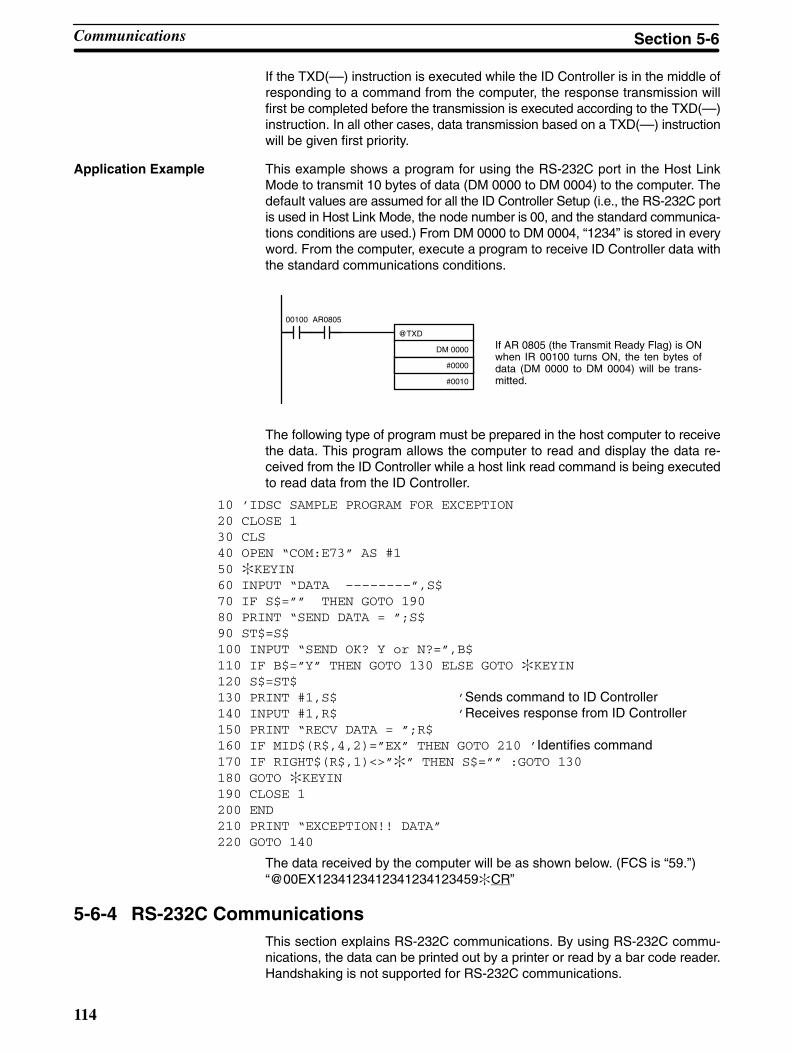
114
If the TXD(––) instruction is executed while the ID Controller is in the middle ofresponding to a command from the computer, the response transmission willfirst be completed before the transmission is executed according to the TXD(––)instruction. In all other cases, data transmission based on a TXD(––) instructionwill be given first priority.
Application Example This example shows a program for using the RS-232C port in the Host LinkMode to transmit 10 bytes of data (DM 0000 to DM 0004) to the computer. Thedefault values are assumed for all the ID Controller Setup (i.e., the RS-232C portis used in Host Link Mode, the node number is 00, and the standard communica-tions conditions are used.) From DM 0000 to DM 0004, “1234” is stored in everyword. From the computer, execute a program to receive ID Controller data withthe standard communications conditions.
@TXD
DM 0000
#0000
#0010
00100 AR0805
If AR 0805 (the Transmit Ready Flag) is ONwhen IR 00100 turns ON, the ten bytes ofdata (DM 0000 to DM 0004) will be trans-mitted.
The following type of program must be prepared in the host computer to receivethe data. This program allows the computer to read and display the data re-ceived from the ID Controller while a host link read command is being executedto read data from the ID Controller.
10 ’IDSC SAMPLE PROGRAM FOR EXCEPTION20 CLOSE 130 CLS40 OPEN “COM:E73” AS #150 KEYIN60 INPUT “DATA ––––––––”,S$70 IF S$=”” THEN GOTO 19080 PRINT “SEND DATA = ”;S$90 ST$=S$100 INPUT “SEND OK? Y or N?=”,B$110 IF B$=”Y” THEN GOTO 130 ELSE GOTO KEYIN120 S$=ST$130 PRINT #1,S$ ’Sends command to ID Controller140 INPUT #1,R$ ’Receives response from ID Controller150 PRINT “RECV DATA = ”;R$160 IF MID$(R$,4,2)=”EX” THEN GOTO 210 ’Identifies command 170 IF RIGHT$(R$,1)<>”” THEN S$=”” :GOTO 130180 GOTO KEYIN190 CLOSE 1200 END210 PRINT “EXCEPTION!! DATA”220 GOTO 140
The data received by the computer will be as shown below. (FCS is “59.”)“@00EX1234123412341234123459CR”
5-6-4 RS-232C CommunicationsThis section explains RS-232C communications. By using RS-232C commu-nications, the data can be printed out by a printer or read by a bar code reader.Handshaking is not supported for RS-232C communications.
Communications Section 5-6

115
Communications Parameters Communications parameters such as the communication conditions, mode,start code, end code, data received, etc. Set the ID Controller Setup forRS-232C communications (i.e., set bits 12 to 15 of DM 6645 or DM 6650 to 1 )when communicating via RS-232C standards. Always set the same parametersas the other parties in the communications are using.
Start and end codes or the amount of data to be received can be set as shown inthe following diagrams if required for RS-232C communications. This setting isrequired only for RS-232C communications. To use RS-232C communications,the RS-232C must be specified as the communications mode and the commu-nications parameters must be set (see next section).Enabling Start and End Codes
15 0Bit
0 0
End code0: Not set (Amount of reception data specified.)1: Set (End code specified.)2: CR/LF
Start code0: Not set1: Set (Start code specified.)
Defaults: No start code; data reception complete at 256 bytes.
DM 6648: RS-232C portDM 6653: Peripheral port
Specify whether or not a start code is to be set at the beginning of the data, andwhether or not an end code is to be set at the end. Instead of setting the endcode, it is possible to specify the number of bytes to be received before the re-ception operation is completed. Both the codes and the number of bytes of datato be received are set in DM 6649 or DM 6654.Setting the Start Code, End Code, and Amount of Reception Data
15 0Bit
End code or number of bytes to be receivedFor end code: (00 to FF)For amount of reception data: 2 digits hexadecimal, 00 to FF (00: 256 bytes)
Start code 00 to FF
Defaults: No start code; data reception complete at 256 bytes.
DM 6649: RS-232C portDM 6654: Peripheral port
Communications ProcedureTransmissions
1, 2, 3... 1. Check to see that AR 0805 (the RS-232C Port Transmit Ready Flag) orAR 0813 (Peripheral Port Transmit Ready Flag) has turned ON.
2. Use the TXD(––) instruction to transmit the data.
(@)TXD
S
C
N
S: Leading word no. of data to be transmitted
C: Control dataBits 00 to 03
0: Leftmost bytes first1: Rightmost bytes first
Bits 12 to 150: RS-232C port1: Peripheral port
N: Number of bytes to be transmitted (4 digits BCD), 0000 to 0256
From the time this instruction is executed until the data transmission is complete,AR 0805 ( or AR0813 for the peripheral port) will remain OFF. (It will turn ONagain upon completion of the data transmission.)
RS-232C Start and EndCodes and Data Received
Communications Section 5-6

116
Start and end codes are not included when the number of bytes to be transmittedis specified. The largest transmission that can be sent with or without start andend codes in 256 bytes, N will be between 254 and 256 depending on the desig-nations for start and end codes. If the number of bytes to be sent is set to 0000,only the start and end codes will be sent.
Start code Data End code
256 bytes max.
To reset the RS-232C port (i.e., to restore the initial status), turn on SR 25209. Toreset the peripheral port, turn on SR 25208. These bits will turn OFF automati-cally after the reset.
Receptions
1, 2, 3... 1. Confirm that AR 0806 (RS-232C Reception Complete Flag) or AR 0814 (Pe-ripheral Reception Complete Flag) is ON.
2. Use the RXD(––) instruction to receive the data.
(@)RXD
D
C
N
D: Leading word no. for storing reception data
C: Control dataBits 00 to 03
0: Leftmost bytes first1: Rightmost bytes first
Bits 12 to 150: RS-232C port1: Peripheral port
N: Number of bytes stored (4 digits BCD), 0000 to 0256
3. The results of reading the data received will be stored in the AR area. Checkto see that the operation was successfully completed. The contents of thesebits will be reset each time RXD(––) is executed.
RS-232Cport
Peripheralport
Error
AR 0800 toAR 0803
AR 0808 toAR 0811
RS-232C port error code (1 digit BCD) 0: Normalcompletion 1: Parity error 2: Framing error 3: Over-run error
AR 0804 AR0812 Communications error
AR 0807 AR0815 Reception Overrun Flag (After reception was com-pleted, the subsequent data was received before thedata was read by means of the RXD instruction.)
AR 09 AR10 Number of bytes received
To reset the RS-232C port (i.e., to restore the initial status), turn ON SR 25209.To reset the peripheral port, turn ON SR 25208. These bits will turn OFF auto-matically after the reset.
The start code and end code are not included in AR 09 or AR 10 (number of bytesreceived).
Communications Section 5-6

117
Application Example This example shows a program for using the RS-232C port in the RS-232CMode to transmit 10 bytes of data (DM 0100 to DM 0104) to the computer, and tostore the data received from the computer in the DM area beginning withDM 0200. Before executing the program, the following ID Controller Setup set-ting must be made.DM 6645: 1000 (RS-232C port in RS-232C Mode; standard communications
conditions)DM 6648: 2000 (No start code; end code CR/LF)The default values are assumed for all other ID Controller Setup settings. FromDM 0100 to DM 0104, 3132 is stored in every word. From the computer, executea program to receive ID Controller data with the standard communicationsconditions.
@TXD
DM 0100
#0000
#0010
00101 AR0805
@RXD
DM 0200
#0000
AR09
AR0806
DIFU(13) 00101
00100
If AR 0805 (the Transmit Ready Flag) is ONwhen IR 00100 turns ON, the ten bytes of data(DM 0100 to DM 0104) will be transmitted, left-most bytes first.
When AR 0806 (Reception Completed Flag)goes ON, the number of bytes of data specifiedin AR 09 will be read from the ID Controller’sreception buffer and stored in memory startingat DM 0200, leftmost bytes first.
The data will be as follows:“31323132313231323132CR LF”
Communications Section 5-6

118
5-6-5 One-to-one Link CommunicationsIf two ID Controllers are linked one-to-one by connecting them together throughtheir RS-232C ports, they can share common LR areas. When two ID Control-lers are linked one-to-one, one of them will serve as the master and the other asthe slave.
Note The peripheral port cannot be used for 1:1 links.
One-to-one Links A one-to-one link allows two ID Controllers to share common data in their LRareas. As shown in the diagram below, when data is written into a word the LRarea of one of the linked ID Controllers, it will automatically be written identicallyinto the same word of the other ID Controller. Each ID Controller has specifiedwords to which it can write and specified words that are written to by the other IDController. Each can read, but cannot write, the words written by the other IDController.
1
11
Master Slave
Master area
Slave area
Written automatically.
Write “1” Master area
Slave areaWrite
ID Controller
Read/Write Head
Data Carrier
Moving object
ID Controller
Read/Write Head
Data Carrier
Moving object
RS-232C 1:1 link
ID Controller Setup To use a 1:1 link, the only settings necessary are the communications mode andthe link words. Set the communications mode for one of the ID Controllers to the1:1 master and the other to the 1:1 slave, and then set the link words in the IDController designated as the master. Bits 08 to 11 are valid only for the master forlink one-to-one.
The word used by each ID Controller will be as shown in the following table, ac-cording to the settings for the master, slave, and link words.
DM 6645 setting LR 00 to LR 63 LR 00 to LR 31 LR 00 to LR 15
Master words LR00 to LR31 LR00 to LR15 LR00 to LR07
Slave words LR32 to LR63 LR16 to LR31 LR08 to LR15
Communications Section 5-6
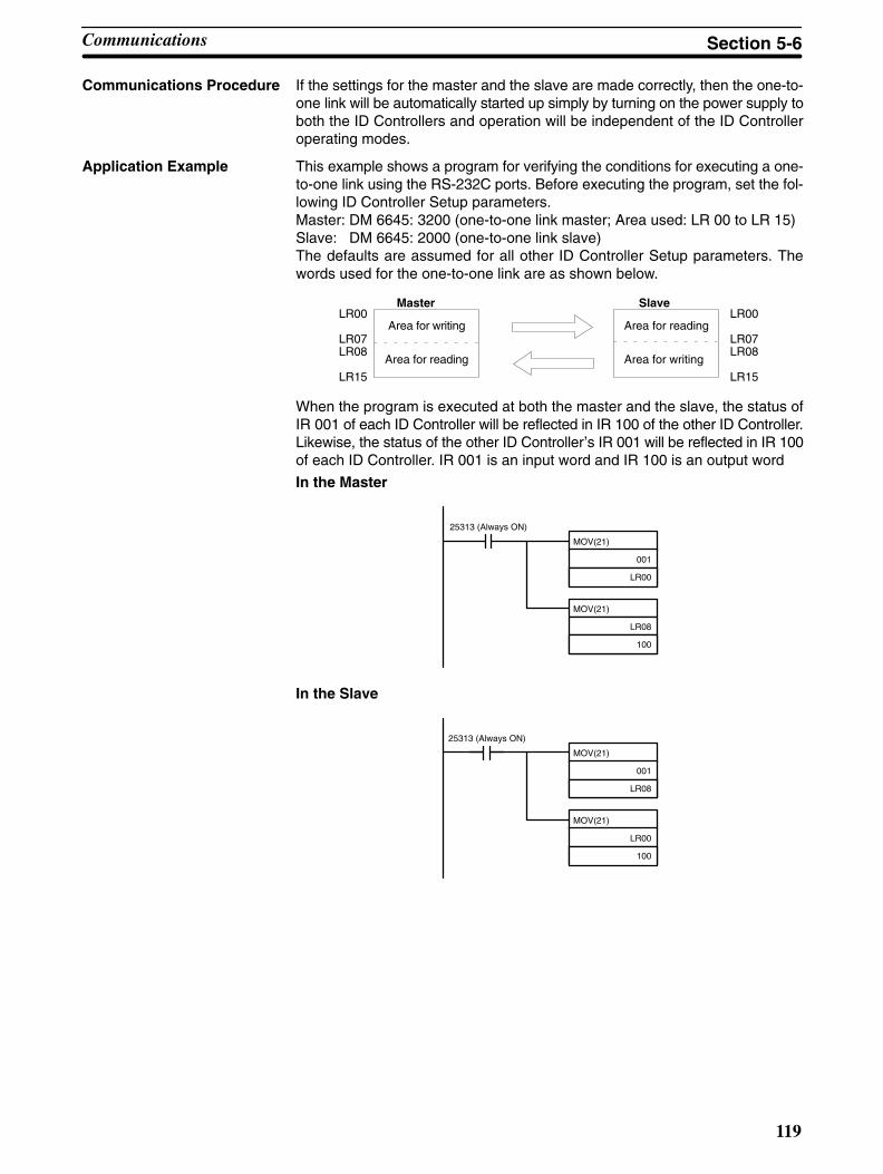
119
Communications Procedure If the settings for the master and the slave are made correctly, then the one-to-one link will be automatically started up simply by turning on the power supply toboth the ID Controllers and operation will be independent of the ID Controlleroperating modes.
Application Example This example shows a program for verifying the conditions for executing a one-to-one link using the RS-232C ports. Before executing the program, set the fol-lowing ID Controller Setup parameters.Master: DM 6645: 3200 (one-to-one link master; Area used: LR 00 to LR 15)Slave: DM 6645: 2000 (one-to-one link slave)The defaults are assumed for all other ID Controller Setup parameters. Thewords used for the one-to-one link are as shown below.
LR00
LR07LR08
LR15
LR00
LR07LR08
LR15
Master
Area for writing
Area for reading
Slave
Area for writing
Area for reading
When the program is executed at both the master and the slave, the status ofIR 001 of each ID Controller will be reflected in IR 100 of the other ID Controller.Likewise, the status of the other ID Controller’s IR 001 will be reflected in IR 100of each ID Controller. IR 001 is an input word and IR 100 is an output word
In the Master
25313 (Always ON)
MOV(21)
001
LR00
MOV(21)
LR08
100
In the Slave
MOV(21)
001
LR08
MOV(21)
LR00
100
25313 (Always ON)
Communications Section 5-6

120
5-6-6 NT Link CommunicationsThe setting and procedures required to communicate with a Programmable Ter-minal (PT) connected to the ID Controller via an NT link are described in this sec-tion.
An NT link allows you to connect a PT to the RS-232C port via a special cable toallow direct data access between the PT and the ID Controlling using a specialcommunications system developed by OMRON.
Displays on the PT can be generated from ID Controller data and data input fromthe PT can be written to ID Controller memory. Because the PT can directly ac-cess and control bit and word data in the ID controller, it can be connected to theID Controller without necessarily requiring changes to the ladder-diagram pro-gram. This lightens the load on the ID Controller and makes program develop-ment far more efficient.
Note NT links are not possible on the peripheral port.
ID Controller Setup Set bits 12 to 15 of DM 6645 to “4” to specify an NT link for the RS-232C port. Pin5 on the ID Controller’s DIP switch must be turned OFF to enable this setting.
Communications Procedure As long as the proper setting is made in the ID Controller Setup and as long asthe PT and ID Controller and connected with the proper Connecting Cable, theNT link will be established automatically as soon as power is turned on to the IDController and the PT. The PT will then be able to freely read the contents of IDController data areas, such as the DM area, IR area, SR area, TIM/CNT area,etc.
Communications Section 5-6
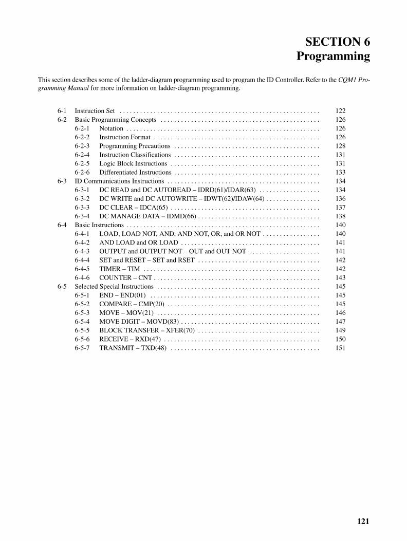
121
SECTION 6Programming
This section describes some of the ladder-diagram programming used to program the ID Controller. Refer to the CQM1 Pro-gramming Manual for more information on ladder-diagram programming.
6-1 Instruction Set 122. . . . . . . . . . . . . . . . . . . . . . . . . . . . . . . . . . . . . . . . . . . . . . . . . . . . . . . . . . . 6-2 Basic Programming Concepts 126. . . . . . . . . . . . . . . . . . . . . . . . . . . . . . . . . . . . . . . . . . . . . . .
6-2-1 Notation 126. . . . . . . . . . . . . . . . . . . . . . . . . . . . . . . . . . . . . . . . . . . . . . . . . . . . . . . . . 6-2-2 Instruction Format 126. . . . . . . . . . . . . . . . . . . . . . . . . . . . . . . . . . . . . . . . . . . . . . . . . 6-2-3 Programming Precautions 128. . . . . . . . . . . . . . . . . . . . . . . . . . . . . . . . . . . . . . . . . . . 6-2-4 Instruction Classifications 131. . . . . . . . . . . . . . . . . . . . . . . . . . . . . . . . . . . . . . . . . . . 6-2-5 Logic Block Instructions 131. . . . . . . . . . . . . . . . . . . . . . . . . . . . . . . . . . . . . . . . . . . . 6-2-6 Differentiated Instructions 133. . . . . . . . . . . . . . . . . . . . . . . . . . . . . . . . . . . . . . . . . . .
6-3 ID Communications Instructions 134. . . . . . . . . . . . . . . . . . . . . . . . . . . . . . . . . . . . . . . . . . . . . 6-3-1 DC READ and DC AUTOREAD – IDRD(61)/IDAR(63) 134. . . . . . . . . . . . . . . . . . 6-3-2 DC WRITE and DC AUTOWRITE – IDWT(62)/IDAW(64) 136. . . . . . . . . . . . . . . . 6-3-3 DC CLEAR – IDCA(65) 137. . . . . . . . . . . . . . . . . . . . . . . . . . . . . . . . . . . . . . . . . . . . 6-3-4 DC MANAGE DATA – IDMD(66) 138. . . . . . . . . . . . . . . . . . . . . . . . . . . . . . . . . . . .
6-4 Basic Instructions 140. . . . . . . . . . . . . . . . . . . . . . . . . . . . . . . . . . . . . . . . . . . . . . . . . . . . . . . . . 6-4-1 LOAD, LOAD NOT, AND, AND NOT, OR, and OR NOT 140. . . . . . . . . . . . . . . . . 6-4-2 AND LOAD and OR LOAD 141. . . . . . . . . . . . . . . . . . . . . . . . . . . . . . . . . . . . . . . . . 6-4-3 OUTPUT and OUTPUT NOT – OUT and OUT NOT 141. . . . . . . . . . . . . . . . . . . . . 6-4-4 SET and RESET – SET and RSET 142. . . . . . . . . . . . . . . . . . . . . . . . . . . . . . . . . . . . 6-4-5 TIMER – TIM 142. . . . . . . . . . . . . . . . . . . . . . . . . . . . . . . . . . . . . . . . . . . . . . . . . . . . 6-4-6 COUNTER – CNT 143. . . . . . . . . . . . . . . . . . . . . . . . . . . . . . . . . . . . . . . . . . . . . . . . .
6-5 Selected Special Instructions 145. . . . . . . . . . . . . . . . . . . . . . . . . . . . . . . . . . . . . . . . . . . . . . . . 6-5-1 END – END(01) 145. . . . . . . . . . . . . . . . . . . . . . . . . . . . . . . . . . . . . . . . . . . . . . . . . . 6-5-2 COMPARE – CMP(20) 145. . . . . . . . . . . . . . . . . . . . . . . . . . . . . . . . . . . . . . . . . . . . . 6-5-3 MOVE – MOV(21) 146. . . . . . . . . . . . . . . . . . . . . . . . . . . . . . . . . . . . . . . . . . . . . . . . 6-5-4 MOVE DIGIT – MOVD(83) 147. . . . . . . . . . . . . . . . . . . . . . . . . . . . . . . . . . . . . . . . . 6-5-5 BLOCK TRANSFER – XFER(70) 149. . . . . . . . . . . . . . . . . . . . . . . . . . . . . . . . . . . . 6-5-6 RECEIVE – RXD(47) 150. . . . . . . . . . . . . . . . . . . . . . . . . . . . . . . . . . . . . . . . . . . . . . 6-5-7 TRANSMIT – TXD(48) 151. . . . . . . . . . . . . . . . . . . . . . . . . . . . . . . . . . . . . . . . . . . .
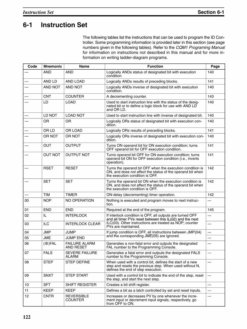
122
6-1 Instruction Set
The following tables list the instructions that can be used to program the ID Con-troller. Some programming information is provided later in this section (see pagenumbers given in the following tables). Refer to the CQM1 Programing Manualfor information on instructions not described in this manual and for more in-formation on writing ladder-diagram programs.
Code Mnemonic Name Function Page
— AND AND Logically ANDs status of designated bit with executioncondition.
140
— AND LD AND LOAD Logically ANDs results of preceding blocks. 141
— AND NOT AND NOT Logically ANDs inverse of designated bit with executioncondition.
140
— CNT COUNTER A decrementing counter. 143
— LD LOAD Used to start instruction line with the status of the desig-nated bit or to define a logic block for use with AND LDand OR LD.
140
— LD NOT LOAD NOT Used to start instruction line with inverse of designated bit. 140
— OR OR Logically ORs status of designated bit with execution con-dition.
140
— OR LD OR LOAD Logically ORs results of preceding blocks. 141
— OR NOT OR NOT Logically ORs inverse of designated bit with execution con-dition.
140
— OUT OUTPUT Turns ON operand bit for ON execution condition; turnsOFF operand bit for OFF execution condition.
141
— OUT NOT OUTPUT NOT Turns operand bit OFF for ON execution condition; turnsoperand bit ON for OFF execution condition (i.e., invertsoperation).
141
— RSET RESET Turns the operand bit OFF when the execution condition isON, and does not affect the status of the operand bit whenthe execution condition is OFF.
142
— SET SET Turns the operand bit ON when the execution condition isON, and does not affect the status of the operand bit whenthe execution condition is OFF.
142
— TIM TIMER ON-delay (decrementing) timer operation. 142
00 NOP NO OPERATION Nothing is executed and program moves to next instruc-tion.
---
01 END END Required at the end of the program. 145
02 IL INTERLOCK If interlock condition is OFF, all outputs are turned OFFand all timer PVs reset between this IL(02) and the next
---
03 ILC INTERLOCK CLEARand all timer PVs reset between this IL(02) and the nextILC(03). Other instructions are treated as NOP; counterPVs are maintained.
---
04 JMP JUMP If jump condition is OFF, all instructions between JMP(04)d th di JME(05) i d
---
05 JME JUMP END
j p , ( )and the corresponding JME(05) are ignored. ---
06 (@)FAL FAILURE ALARMAND RESET
Generates a non-fatal error and outputs the designatedFAL number to the Programming Console.
---
07 FALS SEVERE FAILUREALARM
Generates a fatal error and outputs the designated FALSnumber to the Programming Console.
---
08 STEP STEP DEFINE When used with a control bit, defines the start of a newstep and resets the previous step. When used without N,defines the end of step execution.
---
09 SNXT STEP START Used with a control bit to indicate the end of the step, resetthe step, and start the next step.
---
10 SFT SHIFT REGISTER Creates a bit shift register. ---
11 KEEP KEEP Defines a bit as a latch controlled by set and reset inputs. ---
12 CNTR REVERSIBLECOUNTER
Increases or decreases PV by one whenever the incre-ment input or decrement input signals, respectively, gofrom OFF to ON.
---
Instruction Set Section 6-1

123
Code PageFunctionNameMnemonic
13 DIFU DIFFERENTIATE UP Turns ON the designated bit for one cycle on the risingedge of the input signal.
---
14 DIFD DIFFERENTIATEDOWN
Turns ON the bit for one cycle on the trailing edge. ---
15 TIMH HIGH-SPEED TIMER A high-speed, ON-delay (decrementing) timer. ---
16 (@)WSFT WORD SHIFT Shifts data between starting and ending words in wordunits, writing zeros into starting word.
---
17 (@)ASFT ASYNCHRONOUSSHIFT REGISTER
Creates a shift register that exchanges the contents ofadjacent words when one of the words is zero and the oth-er is not.
---
18 (@)SRCH DATA SEARCH Searches the specified range of memory for the specifieddata. Outputs the word address(es) of words in the rangethat contain the data.
---
19 (@)MCMP MULTI-WORDCOMPARE
Compares a block of 16 consecutive words to anotherblock of 16 consecutive words.
---
20 CMP COMPARE Compares the contents of two words and outputs result toGR, EQ, and LE Flags.
145
21 (@)MOV MOVE Copies source data (word or constant) to destination word. 146
22 (@)MVN MOVE NOT Inverts source data (word or constant) and then copies it todestination word.
---
23 (@)BIN BCD TO BINARY Converts four-digit, BCD data in source word into 16-bitbinary data, and outputs converted data to result word.
---
24 (@)BCD BINARY TO BCD Converts binary data in source word into BCD, and outputsconverted data to result word.
---
25 (@)ASL ARITHMETIC SHIFTLEFT
Shifts each bit in single word of data one bit to left, with CY. ---
26 (@)ASR ARITHMETIC SHIFTRIGHT
Shifts each bit in single word of data one bit to right, withCY.
---
27 (@)ROL ROTATE LEFT Rotates bits in single word of data one bit to left, with CY. ---
28 (@)ROR ROTATE RIGHT Rotates bits in single word of data one bit to right, with CY. ---
29 (@)COM COMPLEMENT Inverts bit status of one word of data. ---
30 (@)ADD BCD ADD Adds two four-digit BCD values and content of CY, andoutputs result to specified result word.
---
31 (@)SUB BCD SUBTRACT Subtracts a four-digit BCD value and CY from anotherfour-digit BCD value and outputs result to the result word.
---
32 (@)MUL BCD MULTIPLY Multiplies two four-digit BCD values and outputs result tospecified result words.
---
33 (@)DIV BCD DIVIDE Divides four-digit BCD dividend by four-digit BCD divisorand outputs result to specified result words.
---
34 (@)ANDW LOGICAL AND Logically ANDs two 16-bit input words and sets corre-sponding bit in result word if corresponding bits in inputwords are both ON.
---
35 (@)ORW LOGICAL OR Logically ORs two 16-bit input words and sets correspond-ing bit in result word if one or both of corresponding bits ininput data are ON.
---
36 (@)XORW EXCLUSIVE OR Exclusively ORs two 16-bit input words and sets bit in re-sult word when corresponding bits in input words differ instatus.
---
37 (@)XNRW EXCLUSIVE NOR Exclusively NORs two 16-bit input words and sets bit inresult word when corresponding bits in input words aresame in status.
---
38 (@)INC BCD INCREMENT Increments four-digit BCD word by one. ---
39 (@)DEC BCD DECREMENT Decrements four-digit BCD word by one. ---
40 (@)STC SET CARRY Sets carry flag (i.e., turns CY ON). ---
41 (@)CLC CLEAR CARRY Clears carry flag (i.e, turns CY OFF). ---
46 (@)MSG MESSAGE Displays a 16-character message on the ProgrammingConsole display.
---
47 (@)RXD RECEIVE Receives data via a communications port. 150
Instruction Set Section 6-1

124
Code PageFunctionNameMnemonic
48 (@)TXD TRANSMIT Sends data via a communications port. 151
50 (@)ADB BINARY ADD Adds two four-digit hexadecimal values and content of CY,and outputs result to specified result word.
---
51 (@)SBB BINARY SUBTRACT Subtracts a four-digit hexadecimal value and CY fromanother four-digit hexadecimal value and outputs result tothe result word.
---
52 (@)MLB BINARY MULTIPLY Multiplies two four-digit hexadecimal values and outputsresult to specified result words.
---
53 (@)DVB BINARY DIVIDE Divides four-digit hexadecimal dividend by four-digit hexa-decimal divisor and outputs result to specified result words.
---
54 (@)ADDL DOUBLE BCD ADD Adds two eight-digit values (2 words each) and content ofCY, and outputs result to specified result words.
---
55 (@)SUBL DOUBLE BCDSUBTRACT
Subtracts an eight-digit BCD value and CY from anothereight-digit BCD value and outputs result to the resultwords.
---
56 (@)MULL DOUBLE BCDMULTIPLY
Multiplies two eight-digit BCD values and outputs result tospecified result words.
---
57 (@)DIVL DOUBLE BCDDIVIDE
Divides eight-digit BCD dividend by eight-digit BCD divisorand outputs result to specified result words.
---
58 (@)BINL DOUBLE BCD TODOUBLE BINARY
Converts BCD value in two consecutive source words intobinary and outputs converted data to two consecutive re-sult words.
---
59 (@)BCDL DOUBLE BINARY TODOUBLE BCD
Converts binary value in two consecutive source wordsinto BCD and outputs converted data to two consecutiveresult words.
---
60 CMPL DOUBLE COMPARE Compares two eight-digit hexadecimal values. ---
61 (@)IDRD DC READ Reads data from memory in the Data Carrier. 134
62 (@)IDWT DC WRITE Writes data to memory in the Data Carrier. 136
63 (@)IDAR DC AUTOREAD Waits for approach of a Data Carrier and then reads data. 134
64 (@)IDAW DC AUTOWRITE Waits for approach of a Data Carrier and then writes data. 136
65 (@)IDCA DC CLEAR Initializes memory in the Data Carrier with the specifieddata.
137
66 (@)IDMD DC MANAGE DATA Checks memory in the Data Carrier. Also manages thewrite life of Data Carriers.
138
67 (@)BCNT BIT COUNTER Counts the total number of bits that are ON in the specifiedblock of words.
---
68 (@)BCMP BLOCK COMPARE Judges whether the value of a word is within 16 ranges(defined by lower and upper limits).
---
69 (@)STIM INTERVAL TIMER Controls interval timers used to perform scheduled inter-rupts.
---
70 (@)XFER BLOCK TRANSFER Moves content of several consecutive source words toconsecutive destination words.
149
71 (@)BSET BLOCK SET Copies content of one word or constant to several consec-utive words.
---
72 (@)ROOT SQUARE ROOT Computes square root of eight-digit BCD value and out-puts truncated four-digit integer result to specified resultword.
---
73 (@)XCHG DATA EXCHANGE Exchanges contents of two different words. ---
74 (@)SLD ONE DIGIT SHIFTLEFT
Left shifts data between starting and ending words by onedigit (four bits).
---
75 (@)SRD ONE DIGIT SHIFTRIGHT
Right shifts data between starting and ending words byone digit (four bits).
---
76 (@)MLPX 4-TO-16 DECODER Converts up to four hexadecimal digits in source word intodecimal values from 0 to 15 and turns ON, in resultword(s), bit(s) whose position corresponds to convertedvalue.
---
77 (@)DMPX 16-TO-4 ENCODER Determines position of highest ON bit in source word(s)and turns ON corresponding bit(s) in result word.
---
Instruction Set Section 6-1
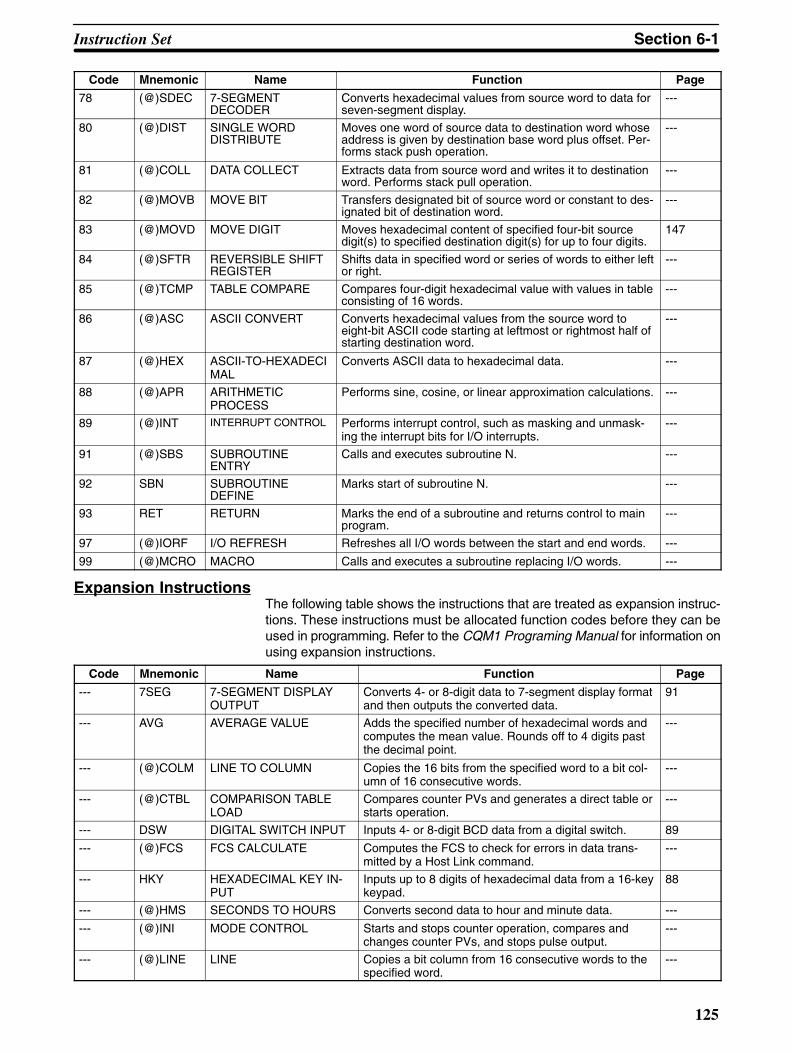
125
Code PageFunctionNameMnemonic
78 (@)SDEC 7-SEGMENTDECODER
Converts hexadecimal values from source word to data forseven-segment display.
---
80 (@)DIST SINGLE WORDDISTRIBUTE
Moves one word of source data to destination word whoseaddress is given by destination base word plus offset. Per-forms stack push operation.
---
81 (@)COLL DATA COLLECT Extracts data from source word and writes it to destinationword. Performs stack pull operation.
---
82 (@)MOVB MOVE BIT Transfers designated bit of source word or constant to des-ignated bit of destination word.
---
83 (@)MOVD MOVE DIGIT Moves hexadecimal content of specified four-bit sourcedigit(s) to specified destination digit(s) for up to four digits.
147
84 (@)SFTR REVERSIBLE SHIFTREGISTER
Shifts data in specified word or series of words to either leftor right.
---
85 (@)TCMP TABLE COMPARE Compares four-digit hexadecimal value with values in tableconsisting of 16 words.
---
86 (@)ASC ASCII CONVERT Converts hexadecimal values from the source word toeight-bit ASCII code starting at leftmost or rightmost half ofstarting destination word.
---
87 (@)HEX ASCII-TO-HEXADECIMAL
Converts ASCII data to hexadecimal data. ---
88 (@)APR ARITHMETICPROCESS
Performs sine, cosine, or linear approximation calculations. ---
89 (@)INT INTERRUPT CONTROL Performs interrupt control, such as masking and unmask-ing the interrupt bits for I/O interrupts.
---
91 (@)SBS SUBROUTINEENTRY
Calls and executes subroutine N. ---
92 SBN SUBROUTINEDEFINE
Marks start of subroutine N. ---
93 RET RETURN Marks the end of a subroutine and returns control to mainprogram.
---
97 (@)IORF I/O REFRESH Refreshes all I/O words between the start and end words. ---
99 (@)MCRO MACRO Calls and executes a subroutine replacing I/O words. ---
Expansion InstructionsThe following table shows the instructions that are treated as expansion instruc-tions. These instructions must be allocated function codes before they can beused in programming. Refer to the CQM1 Programing Manual for information onusing expansion instructions.
Code Mnemonic Name Function Page
--- 7SEG 7-SEGMENT DISPLAYOUTPUT
Converts 4- or 8-digit data to 7-segment display formatand then outputs the converted data.
91
--- AVG AVERAGE VALUE Adds the specified number of hexadecimal words andcomputes the mean value. Rounds off to 4 digits pastthe decimal point.
---
--- (@)COLM LINE TO COLUMN Copies the 16 bits from the specified word to a bit col-umn of 16 consecutive words.
---
--- (@)CTBL COMPARISON TABLELOAD
Compares counter PVs and generates a direct table orstarts operation.
---
--- DSW DIGITAL SWITCH INPUT Inputs 4- or 8-digit BCD data from a digital switch. 89
--- (@)FCS FCS CALCULATE Computes the FCS to check for errors in data trans-mitted by a Host Link command.
---
--- HKY HEXADECIMAL KEY IN-PUT
Inputs up to 8 digits of hexadecimal data from a 16-keykeypad.
88
--- (@)HMS SECONDS TO HOURS Converts second data to hour and minute data. ---
--- (@)INI MODE CONTROL Starts and stops counter operation, compares andchanges counter PVs, and stops pulse output.
---
--- (@)LINE LINE Copies a bit column from 16 consecutive words to thespecified word.
---
Instruction Set Section 6-1
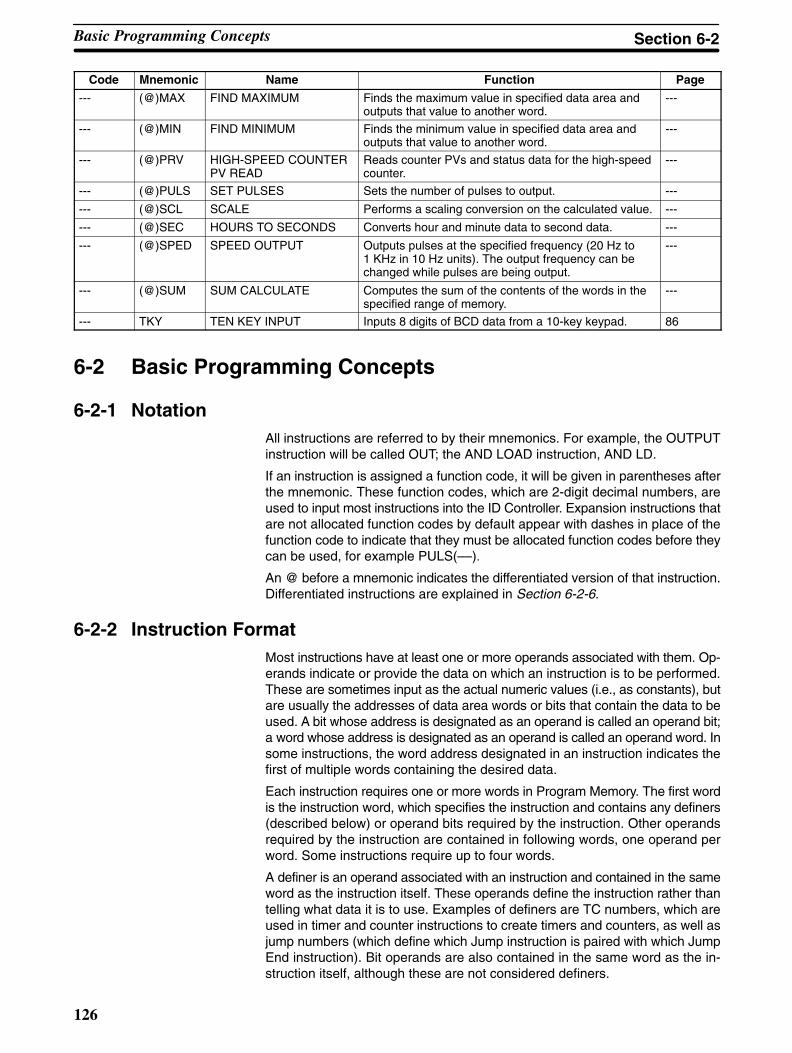
126
Code PageFunctionNameMnemonic
--- (@)MAX FIND MAXIMUM Finds the maximum value in specified data area andoutputs that value to another word.
---
--- (@)MIN FIND MINIMUM Finds the minimum value in specified data area andoutputs that value to another word.
---
--- (@)PRV HIGH-SPEED COUNTERPV READ
Reads counter PVs and status data for the high-speedcounter.
---
--- (@)PULS SET PULSES Sets the number of pulses to output. ---
--- (@)SCL SCALE Performs a scaling conversion on the calculated value. ---
--- (@)SEC HOURS TO SECONDS Converts hour and minute data to second data. ---
--- (@)SPED SPEED OUTPUT Outputs pulses at the specified frequency (20 Hz to1 KHz in 10 Hz units). The output frequency can bechanged while pulses are being output.
---
--- (@)SUM SUM CALCULATE Computes the sum of the contents of the words in thespecified range of memory.
---
--- TKY TEN KEY INPUT Inputs 8 digits of BCD data from a 10-key keypad. 86
6-2 Basic Programming Concepts
6-2-1 NotationAll instructions are referred to by their mnemonics. For example, the OUTPUTinstruction will be called OUT; the AND LOAD instruction, AND LD.
If an instruction is assigned a function code, it will be given in parentheses afterthe mnemonic. These function codes, which are 2-digit decimal numbers, areused to input most instructions into the ID Controller. Expansion instructions thatare not allocated function codes by default appear with dashes in place of thefunction code to indicate that they must be allocated function codes before theycan be used, for example PULS(––).
An @ before a mnemonic indicates the differentiated version of that instruction.Differentiated instructions are explained in Section 6-2-6.
6-2-2 Instruction FormatMost instructions have at least one or more operands associated with them. Op-erands indicate or provide the data on which an instruction is to be performed.These are sometimes input as the actual numeric values (i.e., as constants), butare usually the addresses of data area words or bits that contain the data to beused. A bit whose address is designated as an operand is called an operand bit;a word whose address is designated as an operand is called an operand word. Insome instructions, the word address designated in an instruction indicates thefirst of multiple words containing the desired data.
Each instruction requires one or more words in Program Memory. The first wordis the instruction word, which specifies the instruction and contains any definers(described below) or operand bits required by the instruction. Other operandsrequired by the instruction are contained in following words, one operand perword. Some instructions require up to four words.
A definer is an operand associated with an instruction and contained in the sameword as the instruction itself. These operands define the instruction rather thantelling what data it is to use. Examples of definers are TC numbers, which areused in timer and counter instructions to create timers and counters, as well asjump numbers (which define which Jump instruction is paired with which JumpEnd instruction). Bit operands are also contained in the same word as the in-struction itself, although these are not considered definers.
Basic Programming Concepts Section 6-2
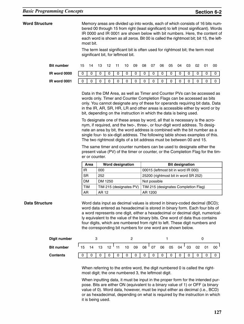
127
Word Structure Memory areas are divided up into words, each of which consists of 16 bits num-bered 00 through 15 from right (least significant) to left (most significant). WordsIR 0000 and IR 0001 are shown below with bit numbers. Here, the content ofeach word is shown as all zeros. Bit 00 is called the rightmost bit; bit 15, the left-most bit.
The term least significant bit is often used for rightmost bit; the term mostsignificant bit, for leftmost bit.
Bit number
IR word 0000 0 0 0 0 0 0 0 0 0 0 0 0 0 0 0 0
IR word 0001 0 0 0 0 0 0 0 0 0 0 0 0 0 0 0 0
15 14 13 12 11 10 09 08 07 06 05 04 03 02 01 00
Data in the DM Area, as well as Timer and Counter PVs can be accessed aswords only. Timer and Counter Completion Flags can be accessed as bitsonly. You cannot designate any of these for operands requiring bit data. Datain the IR, AR, SR, HR, LR and other areas is accessible either by word or bybit, depending on the instruction in which the data is being used.
To designate one of these areas by word, all that is necessary is the acro-nym, if required, and the two-, three-, or four-digit word address. To desig-nate an area by bit, the word address is combined with the bit number as asingle four- to six-digit address. The following table shows examples of this.The two rightmost digits of a bit address must be between 00 and 15.
The same timer and counter numbers can be used to designate either thepresent value (PV) of the timer or counter, or the Completion Flag for the tim-er or counter.
Area Word designation Bit designation
IR 000 00015 (leftmost bit in word IR 000)
SR 252 25200 (rightmost bit in word SR 252)
DM DM 1250 Not possible
TIM TIM 215 (designates PV) TIM 215 (designates Completion Flag)
AR AR 12 AR 1200
Word data input as decimal values is stored in binary-coded decimal (BCD);word data entered as hexadecimal is stored in binary form. Each four bits ofa word represents one digit, either a hexadecimal or decimal digit, numerical-ly equivalent to the value of the binary bits. One word of data thus containsfour digits, which are numbered from right to left. These digit numbers andthe corresponding bit numbers for one word are shown below.
Bit number
Contents 0 0 0 0 0 0 0 0 0 0 0 0 0 0 0 0
15 14 13 12 11 10 09 08 07 06 05 04 03 02 01 00
Digit number 3 2 1 0
When referring to the entire word, the digit numbered 0 is called the right-most digit; the one numbered 3, the leftmost digit.
When inputting data, it must be input in the proper form for the intended pur-pose. Bits are either ON (equivalent to a binary value of 1) or OFF (a binaryvalue of 0). Word data, however, must be input either as decimal (i.e., BCD)or as hexadecimal, depending on what is required by the instruction in whichit is being used.
Data Structure
Basic Programming Concepts Section 6-2
128
Binary and hexadecimal can be easily converted back and forth becauseeach four bits of a binary number is numerically equivalent to one digit of ahexadecimal number. The binary number 0101 1111 0101 1111 is convertedto hexadecimal by considering each set of four bits in order from the right.Binary 1111 is hexadecimal F; binary 0101 is hexadecimal 5. The hexadeci-mal equivalent would thus be 5F5F, or 24,415 in decimal (163 x 5 + 162 x 15+ 16 x 5 + 15).
Decimal and BCD are easily converted back and forth. In this case, eachBCD digit (i.e., each group of four BCD bits) is numerically equivalent to thecorresponding decimal digit. The BCD bits 0101 0111 0101 0111 are con-verted to decimal by considering each four bits from the right. Binary 0101 isdecimal 5; binary 0111 is decimal 7. The decimal equivalent would thus be5,757. Note that this is not the same numeric value as the hexadecimalequivalent of 0101 0111 0101 0111, which would be 5,757 hexadecimal, or22,359 in decimal (163 x 5 + 162 x 7 + 16 x 5 + 7).
Because each four BCD binary bits must be numerically equivalent to a deci-mal value, any four bit combination numerically greater than 9 cannot beused, e.g., 1011 is not allowed because it is numerically equivalent to 11,which cannot be expressed as a single digit in decimal notation. The binarybits 1011 are allowed in hexadecimal and are equivalent to the hexadecimaldigit B.
There are instructions provided to convert data between BCD and hexadeci-mal.
Decimal points are used in timers, although they are assumed and not actu-ally input into memory. The least significant digit represents tenths of a sec-ond. All arithmetic instructions operate on integers only. When inputting datafor use in special applications, be sure to check on the type of data requiredfor the application.
6-2-3 Programming PrecautionsThe number of conditions that can be used in series or parallel is unlimitedas long as the memory capacity of the ID Controller is not exceeded. There-fore, use as many conditions as required to draw a clear diagram.
Converting Different Formsof Data
Decimal Points
Basic Programming Concepts Section 6-2
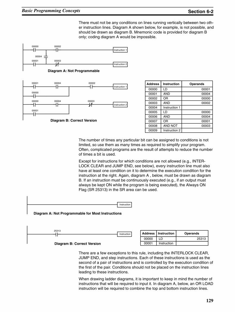
129
There must not be any conditions on lines running vertically between two oth-er instruction lines. Diagram A shown below, for example, is not possible, andshould be drawn as diagram B. Mnemonic code is provided for diagram Bonly; coding diagram A would be impossible.
Instruction 2
Instruction 1
00002
00003
00000
00001
00004
Diagram A: Not Programmable
Instruction 1
00004
00003
00000
00001
Diagram B: Correct Version
00002
Instruction 2
0000400000
00001
Address Instruction Operands
00000 LD 00001
00001 AND 00004
00002 OR 00000
00003 AND 00002
00004 Instruction 1
00005 LD 00000
00006 AND 00004
00007 OR 00001
00008 AND NOT 00003
00009 Instruction 2
The number of times any particular bit can be assigned to conditions is notlimited, so use them as many times as required to simplify your program.Often, complicated programs are the result of attempts to reduce the numberof times a bit is used.
Except for instructions for which conditions are not allowed (e.g., INTER-LOCK CLEAR and JUMP END, see below), every instruction line must alsohave at least one condition on it to determine the execution condition for theinstruction at the right. Again, diagram A , below, must be drawn as diagramB. If an instruction must be continuously executed (e.g., if an output mustalways be kept ON while the program is being executed), the Always ONFlag (SR 25313) in the SR area can be used.
Instruction25313
Instruction
Diagram A: Not Programmable for Most Instructions
Diagram B: Correct Version
Address Instruction Operands
00000 LD 25313
00001 Instruction
There are a few exceptions to this rule, including the INTERLOCK CLEAR,JUMP END, and step instructions. Each of these instructions is used as thesecond of a pair of instructions and is controlled by the execution condition ofthe first of the pair. Conditions should not be placed on the instruction linesleading to these instructions.
When drawing ladder diagrams, it is important to keep in mind the number ofinstructions that will be required to input it. In diagram A, below, an OR LOADinstruction will be required to combine the top and bottom instruction lines.
Basic Programming Concepts Section 6-2
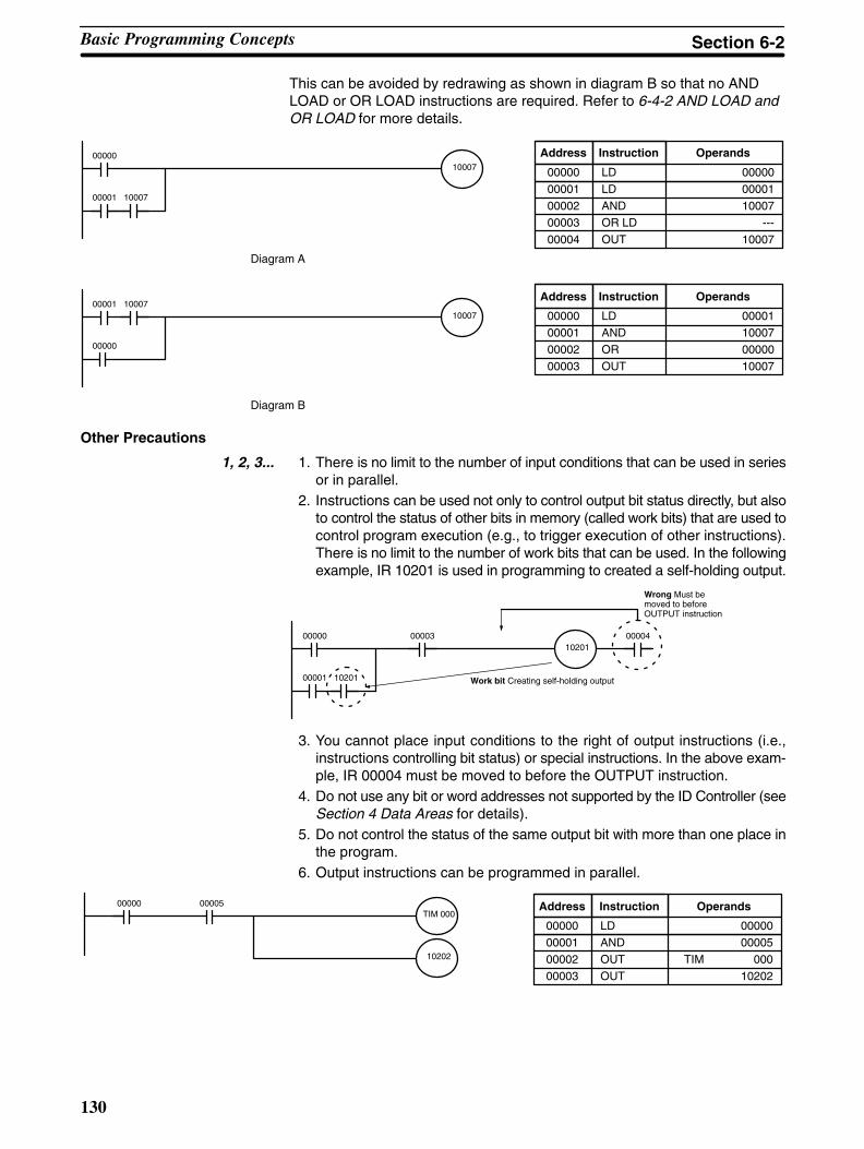
130
This can be avoided by redrawing as shown in diagram B so that no ANDLOAD or OR LOAD instructions are required. Refer to 6-4-2 AND LOAD andOR LOAD for more details.
00000
00001 10007
10007
00001
00000
1000710007
Diagram A
Diagram B
Address Instruction Operands
00000 LD 00000
00001 LD 00001
00002 AND 10007
00003 OR LD ---
00004 OUT 10007
Address Instruction Operands
00000 LD 00001
00001 AND 10007
00002 OR 00000
00003 OUT 10007
Other Precautions
1, 2, 3... 1. There is no limit to the number of input conditions that can be used in seriesor in parallel.
2. Instructions can be used not only to control output bit status directly, but alsoto control the status of other bits in memory (called work bits) that are used tocontrol program execution (e.g., to trigger execution of other instructions).There is no limit to the number of work bits that can be used. In the followingexample, IR 10201 is used in programming to created a self-holding output.
00000
00001 10201
102010000400003
Wrong Must bemoved to beforeOUTPUT instruction
Work bit Creating self-holding output
3. You cannot place input conditions to the right of output instructions (i.e.,instructions controlling bit status) or special instructions. In the above exam-ple, IR 00004 must be moved to before the OUTPUT instruction.
4. Do not use any bit or word addresses not supported by the ID Controller (seeSection 4 Data Areas for details).
5. Do not control the status of the same output bit with more than one place inthe program.
6. Output instructions can be programmed in parallel.
0000500000 Address Instruction Operands
00000 LD 00000
00001 AND 00005
00002 OUT TIM 000
00003 OUT 10202
TIM 000
10202
Basic Programming Concepts Section 6-2
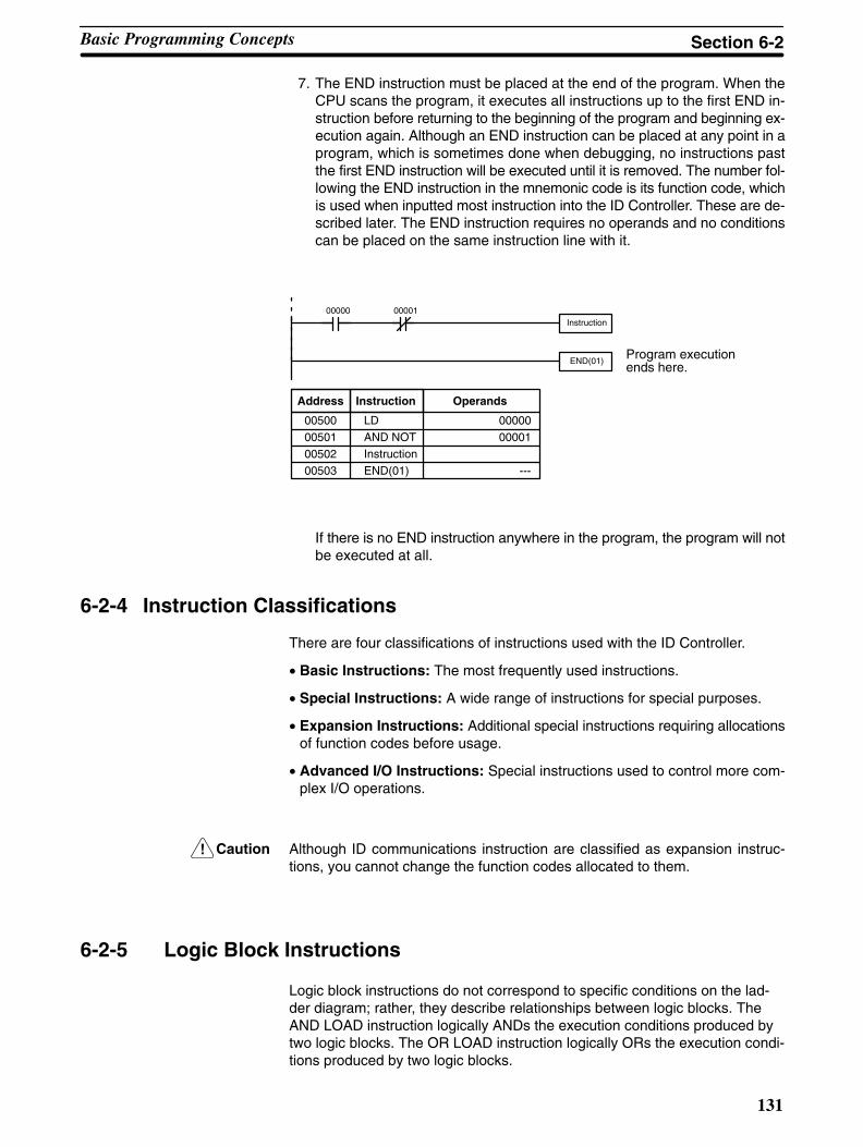
!
131
7. The END instruction must be placed at the end of the program. When theCPU scans the program, it executes all instructions up to the first END in-struction before returning to the beginning of the program and beginning ex-ecution again. Although an END instruction can be placed at any point in aprogram, which is sometimes done when debugging, no instructions pastthe first END instruction will be executed until it is removed. The number fol-lowing the END instruction in the mnemonic code is its function code, whichis used when inputted most instruction into the ID Controller. These are de-scribed later. The END instruction requires no operands and no conditionscan be placed on the same instruction line with it.
Instruction00000 00001
END(01)Program executionends here.
Address Instruction Operands
00500 LD 00000
00501 AND NOT 00001
00502 Instruction
00503 END(01) ---
If there is no END instruction anywhere in the program, the program will notbe executed at all.
6-2-4 Instruction Classifications
There are four classifications of instructions used with the ID Controller.
• Basic Instructions: The most frequently used instructions.
• Special Instructions: A wide range of instructions for special purposes.
• Expansion Instructions: Additional special instructions requiring allocationsof function codes before usage.
• Advanced I/O Instructions: Special instructions used to control more com-plex I/O operations.
Caution Although ID communications instruction are classified as expansion instruc-tions, you cannot change the function codes allocated to them.
6-2-5 Logic Block Instructions
Logic block instructions do not correspond to specific conditions on the lad-der diagram; rather, they describe relationships between logic blocks. TheAND LOAD instruction logically ANDs the execution conditions produced bytwo logic blocks. The OR LOAD instruction logically ORs the execution condi-tions produced by two logic blocks.
Basic Programming Concepts Section 6-2
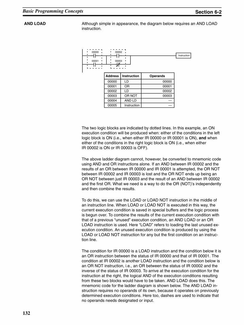
132
Although simple in appearance, the diagram below requires an AND LOADinstruction.
Instruction00002
00003
00000
00001
Address Instruction Operands
00000 LD 00000
00001 OR 00001
00002 LD 00002
00003 OR NOT 00003
00004 AND LD ---
00005 Instruction ---
The two logic blocks are indicated by dotted lines. In this example, an ONexecution condition will be produced when: either of the conditions in the leftlogic block is ON (i.e., when either IR 00000 or IR 00001 is ON), and wheneither of the conditions in the right logic block is ON (i.e., when eitherIR 00002 is ON or IR 00003 is OFF).
The above ladder diagram cannot, however, be converted to mnemonic codeusing AND and OR instructions alone. If an AND between IR 00002 and theresults of an OR between IR 00000 and IR 00001 is attempted, the OR NOTbetween IR 00002 and IR 00003 is lost and the OR NOT ends up being anOR NOT between just IR 00003 and the result of an AND between IR 00002and the first OR. What we need is a way to do the OR (NOT)’s independentlyand then combine the results.
To do this, we can use the LOAD or LOAD NOT instruction in the middle ofan instruction line. When LOAD or LOAD NOT is executed in this way, thecurrent execution condition is saved in special buffers and the logic processis begun over. To combine the results of the current execution condition withthat of a previous “unused” execution condition, an AND LOAD or an ORLOAD instruction is used. Here “LOAD” refers to loading the last unused ex-ecution condition. An unused execution condition is produced by using theLOAD or LOAD NOT instruction for any but the first condition on an instruc-tion line.
The condition for IR 00000 is a LOAD instruction and the condition below it isan OR instruction between the status of IR 00000 and that of IR 00001. Thecondition at IR 00002 is another LOAD instruction and the condition below isan OR NOT instruction, i.e., an OR between the status of IR 00002 and theinverse of the status of IR 00003. To arrive at the execution condition for theinstruction at the right, the logical AND of the execution conditions resultingfrom these two blocks would have to be taken. AND LOAD does this. Themnemonic code for the ladder diagram is shown below. The AND LOAD in-struction requires no operands of its own, because it operates on previouslydetermined execution conditions. Here too, dashes are used to indicate thatno operands needs designated or input.
AND LOAD
Basic Programming Concepts Section 6-2
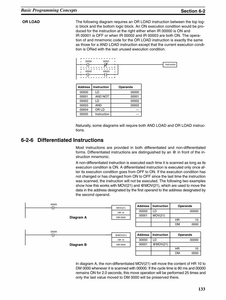
133
The following diagram requires an OR LOAD instruction between the top log-ic block and the bottom logic block. An ON execution condition would be pro-duced for the instruction at the right either when IR 00000 is ON andIR 00001 is OFF or when IR 00002 and IR 00003 are both ON. The opera-tion of and mnemonic code for the OR LOAD instruction is exactly the sameas those for a AND LOAD instruction except that the current execution condi-tion is ORed with the last unused execution condition.
Instruction00000 00001
00002 00003
Address Instruction Operands
00000 LD 00000
00001 AND NOT 00001
00002 LD 00002
00003 AND 00003
00004 OR LD ---
00005 Instruction ---
Naturally, some diagrams will require both AND LOAD and OR LOAD instruc-tions.
6-2-6 Differentiated InstructionsMost instructions are provided in both differentiated and non-differentiatedforms. Differentiated instructions are distinguished by an @ in front of the in-struction mnemonic.
A non-differentiated instruction is executed each time it is scanned as long as itsexecution condition is ON. A differentiated instruction is executed only once af-ter its execution condition goes from OFF to ON. If the execution condition hasnot changed or has changed from ON to OFF since the last time the instructionwas scanned, the instruction will not be executed. The following two examplesshow how this works with MOV(21) and @MOV(21), which are used to move thedata in the address designated by the first operand to the address designated bythe second operand.
00000
MOV(21)
HR 10
DM 0000Diagram A
00000
@MOV(21)
HR 10
DM 0000Diagram B
Address Instruction Operands
Address Instruction Operands
00000 LD 00000
00001 MOV(21)
HR 10
DM 0000
00000 LD 00000
00001 @MOV(21)
HR 10
DM 0000
In diagram A, the non-differentiated MOV(21) will move the content of HR 10 toDM 0000 whenever it is scanned with 00000. If the cycle time is 80 ms and 00000remains ON for 2.0 seconds, this move operation will be performed 25 times andonly the last value moved to DM 0000 will be preserved there.
OR LOAD
Basic Programming Concepts Section 6-2
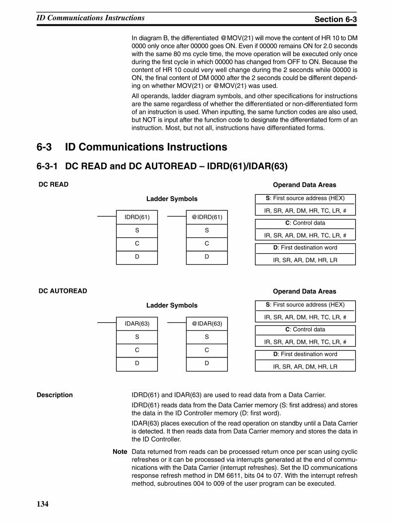
134
In diagram B, the differentiated @MOV(21) will move the content of HR 10 to DM0000 only once after 00000 goes ON. Even if 00000 remains ON for 2.0 secondswith the same 80 ms cycle time, the move operation will be executed only onceduring the first cycle in which 00000 has changed from OFF to ON. Because thecontent of HR 10 could very well change during the 2 seconds while 00000 isON, the final content of DM 0000 after the 2 seconds could be different depend-ing on whether MOV(21) or @MOV(21) was used.
All operands, ladder diagram symbols, and other specifications for instructionsare the same regardless of whether the differentiated or non-differentiated formof an instruction is used. When inputting, the same function codes are also used,but NOT is input after the function code to designate the differentiated form of aninstruction. Most, but not all, instructions have differentiated forms.
6-3 ID Communications Instructions
6-3-1 DC READ and DC AUTOREAD – IDRD(61)/IDAR(63)
S: First source address (HEX)
IR, SR, AR, DM, HR, TC, LR, #
C: Control data
IR, SR, AR, DM, HR, TC, LR, #
Ladder Symbols
Operand Data Areas
D: First destination word
IR, SR, AR, DM, HR, LR
IDRD(61)
S
C
D
@IDRD(61)
S
C
D
DC READ
S: First source address (HEX)
IR, SR, AR, DM, HR, TC, LR, #
C: Control data
IR, SR, AR, DM, HR, TC, LR, #
Ladder Symbols
Operand Data Areas
D: First destination word
IR, SR, AR, DM, HR, LR
IDAR(63)
S
C
D
@IDAR(63)
S
C
D
DC AUTOREAD
Description IDRD(61) and IDAR(63) are used to read data from a Data Carrier.
IDRD(61) reads data from the Data Carrier memory (S: first address) and storesthe data in the ID Controller memory (D: first word).
IDAR(63) places execution of the read operation on standby until a Data Carrieris detected. It then reads data from Data Carrier memory and stores the data inthe ID Controller.
Note Data returned from reads can be processed return once per scan using cyclicrefreshes or it can be processed via interrupts generated at the end of commu-nications with the Data Carrier (interrupt refreshes). Set the ID communicationsresponse refresh method in DM 6611, bits 04 to 07. With the interrupt refreshmethod, subroutines 004 to 009 of the user program can be executed.
ID Communications Instructions Section 6-3

135
Control Data Set the control data (C) as shown in the following table.
Bit(s) Functions Values
00 to 11 Number of bytes(addresses) to read
001 to 256 in BCD
12 None Set to 0.
13 Read data order (in IDController)
0: Leftmost byte first
1: Rightmost byte first
14 None Set to 0.
15 None Set to 0.
Note Up to 256 bytes can be read with the execution of each instructions. All bytesread with one instruction will be refreshed at the same time.
Precautions The addresses that can be specified for the first source word (S) depend on theData Carrier that is being used. Refer to your Data Carrier manual for details.
The content of the control data (C) must be within the specified ranges (seeabove table).
Flags ER: The number of bytes to read (bits 00 to 11 in control data) is not BCD or isout of range.
Indirectly addressed DM word is non-existent. (Content of *DM word isnot BCD, or the DM area boundary has been exceeded.)
SR 23200 (ID Ready Flag) was OFF or another ID communicationsinstruction was being executed.
23300: OFF while instruction is being executed. ON when executed has beencompleted.
23301: OFF while instruction is being executed. ON when executed has beencompleted.
23302: ON when an error has occurred in ID communications.
23306: ON when the end of the service life of the Data Carrier battery has beendetected.
23308 to 23313: Indicate error type with 23302 is ON.
Example Refer to page 79 for an example.
ID Communications Instructions Section 6-3
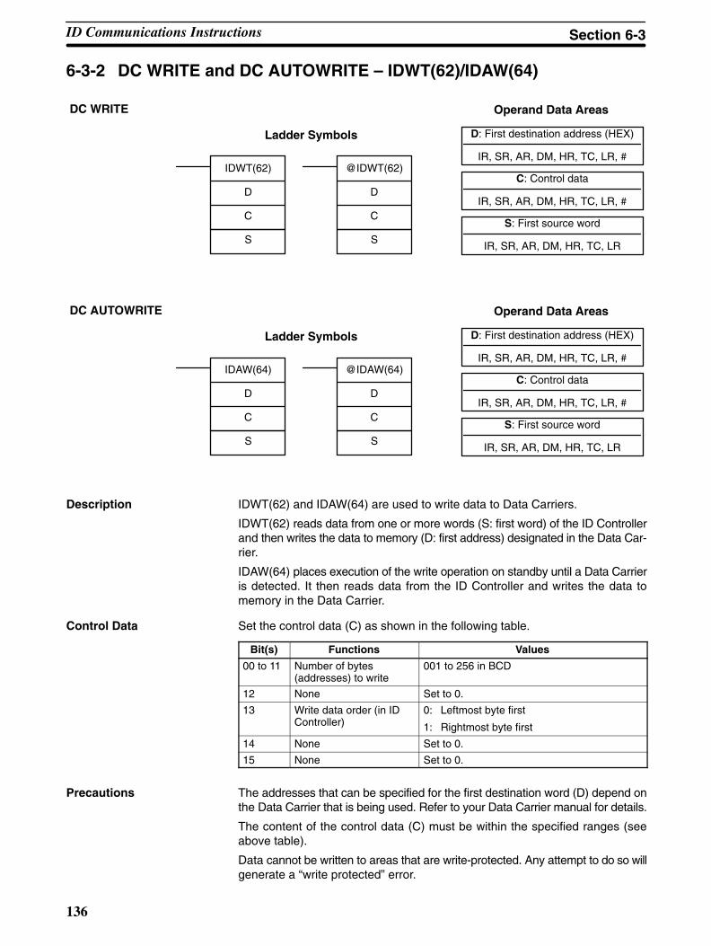
136
6-3-2 DC WRITE and DC AUTOWRITE – IDWT(62)/IDAW(64)
D: First destination address (HEX)
IR, SR, AR, DM, HR, TC, LR, #
C: Control data
IR, SR, AR, DM, HR, TC, LR, #
Ladder Symbols
Operand Data Areas
S: First source word
IR, SR, AR, DM, HR, TC, LR
IDWT(62)
D
C
S
@IDWT(62)
D
C
S
DC WRITE
D: First destination address (HEX)
IR, SR, AR, DM, HR, TC, LR, #
C: Control data
IR, SR, AR, DM, HR, TC, LR, #
Ladder Symbols
Operand Data Areas
S: First source word
IR, SR, AR, DM, HR, TC, LR
IDAW(64)
D
C
S
@IDAW(64)
D
C
S
DC AUTOWRITE
Description IDWT(62) and IDAW(64) are used to write data to Data Carriers.
IDWT(62) reads data from one or more words (S: first word) of the ID Controllerand then writes the data to memory (D: first address) designated in the Data Car-rier.
IDAW(64) places execution of the write operation on standby until a Data Carrieris detected. It then reads data from the ID Controller and writes the data tomemory in the Data Carrier.
Control Data Set the control data (C) as shown in the following table.
Bit(s) Functions Values
00 to 11 Number of bytes(addresses) to write
001 to 256 in BCD
12 None Set to 0.
13 Write data order (in IDController)
0: Leftmost byte first
1: Rightmost byte first
14 None Set to 0.
15 None Set to 0.
Precautions The addresses that can be specified for the first destination word (D) depend onthe Data Carrier that is being used. Refer to your Data Carrier manual for details.
The content of the control data (C) must be within the specified ranges (seeabove table).
Data cannot be written to areas that are write-protected. Any attempt to do so willgenerate a “write protected” error.
ID Communications Instructions Section 6-3

137
Flags ER: The number of bytes to write (bits 00 to 11 in control data) is not BCD oris out of range.
Indirectly addressed DM word is non-existent. (Content of *DM word isnot BCD, or the DM area boundary has been exceeded.)
SR 23200 (ID Ready Flag) was OFF or another ID communicationsinstruction was being executed.
23300: OFF while instruction is being executed. ON when executed has beencompleted.
23301: OFF while instruction is being executed. ON when executed has beencompleted.
23302: ON when an error has occurred in ID communications.
23306: ON when the end of the service life of the Data Carrier battery has beendetected.
23308 to 23313: Indicate error type with 23302 is ON.
Example Refer to page 80 for an example.
6-3-3 DC CLEAR – IDCA(65)
D: First destination address (HEX)
IR, SR, AR, DM, HR, TC, LR, #
C: Control data
IR, SR, AR, DM, HR, TC, LR, #
Ladder Symbols
Operand Data Areas
S: Initialization data
IR, SR, AR, DM, HR, TC, LR
IDCA(65)
D
C
S
@IDCA(65)
D
C
S
Description IDCA(65) initializes the memory (D: first address) of the Data Carrier with desig-nated data (S: initialization data). All data in designated user areas will be initial-ized whether the area is write-protected or not.
Control Data Set the control data (C) as shown in the following table.
Bit(s) Functions Values
00 to 11 Number of bytes(addresses) to clear
000: Clear through last address
001 to 256 in BCD
12 None Set to 0.
13 Write data type (seefollowing explanation forInitialization Data)
0: Bytes (Initializes memory with therightmost digits of specified initialization data)
1: Words (Initializes memory with the bothdigits of specified initialization data, writingthe leftmost byte first)
14 None Set to 0.
15 None Set to 0.
ID Communications Instructions Section 6-3
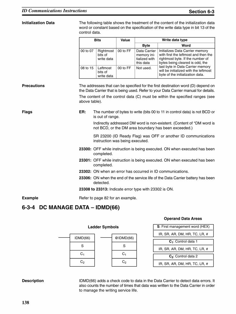
138
Initialization Data The following table shows the treatment of the content of the initialization dataword or constant based on the specification of the write data type in bit 13 of thecontrol data.
Bits Value Write data type
Byte Word
00 to 07 Rightmostbits ofwrite data
00 to FF Data Carriermemory ini-tialized withthis data
Initializes Data Carrier memorywith first the leftmost and then therightmost byte. If the number ofbytes being cleared is odd, thel b i D C i08 to 15 Leftmost
bits ofwrite data
00 to FF Not used.
y g ,last byte in Data Carrier memorywill be initialized with the leftmostbyte of the initialization data.
Precautions The addresses that can be specified for the first destination word (D) depend onthe Data Carrier that is being used. Refer to your Data Carrier manual for details.
The content of the control data (C) must be within the specified ranges (seeabove table).
Flags ER: The number of bytes to write (bits 00 to 11 in control data) is not BCD oris out of range.
Indirectly addressed DM word is non-existent. (Content of *DM word isnot BCD, or the DM area boundary has been exceeded.)
SR 23200 (ID Ready Flag) was OFF or another ID communicationsinstruction was being executed.
23300: OFF while instruction is being executed. ON when executed has beencompleted.
23301: OFF while instruction is being executed. ON when executed has beencompleted.
23302: ON when an error has occurred in ID communications.
23306: ON when the end of the service life of the Data Carrier battery has beendetected.
23308 to 23313: Indicate error type with 23302 is ON.
Example Refer to page 82 for an example.
6-3-4 DC MANAGE DATA – IDMD(66)
S: First management word (HEX)
IR, SR, AR, DM, HR, TC, LR, #
C1: Control data 1
IR, SR, AR, DM, HR, TC, LR, #
Ladder Symbols
Operand Data Areas
C2: Control data 2
IR, SR, AR, DM, HR, TC, LR, #
IDMD(66)
S
C1
C2
@IDMD(66)
S
C1
C2
Description IDMD(66) adds a check code to data in the Data Carrier to detect data errors. Italso counts the number of times that data was written to the Data Carrier in orderto manage the writing service life.
ID Communications Instructions Section 6-3
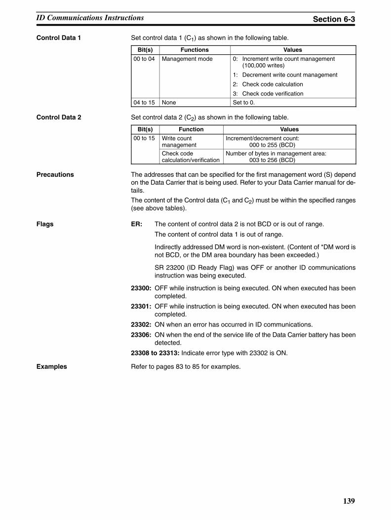
139
Control Data 1 Set control data 1 (C1) as shown in the following table.
Bit(s) Functions Values
00 to 04 Management mode 0: Increment write count management(100,000 writes)
1: Decrement write count management
2: Check code calculation
3: Check code verification
04 to 15 None Set to 0.
Control Data 2 Set control data 2 (C2) as shown in the following table.
Bit(s) Function Values
00 to 15 Write countmanagement
Increment/decrement count: 000 to 255 (BCD)
Check codecalculation/verification
Number of bytes in management area:003 to 256 (BCD)
Precautions The addresses that can be specified for the first management word (S) dependon the Data Carrier that is being used. Refer to your Data Carrier manual for de-tails.
The content of the Control data (C1 and C2) must be within the specified ranges(see above tables).
Flags ER: The content of control data 2 is not BCD or is out of range.
The content of control data 1 is out of range.
Indirectly addressed DM word is non-existent. (Content of *DM word isnot BCD, or the DM area boundary has been exceeded.)
SR 23200 (ID Ready Flag) was OFF or another ID communicationsinstruction was being executed.
23300: OFF while instruction is being executed. ON when executed has beencompleted.
23301: OFF while instruction is being executed. ON when executed has beencompleted.
23302: ON when an error has occurred in ID communications.
23306: ON when the end of the service life of the Data Carrier battery has beendetected.
23308 to 23313: Indicate error type with 23302 is ON.
Examples Refer to pages 83 to 85 for examples.
ID Communications Instructions Section 6-3
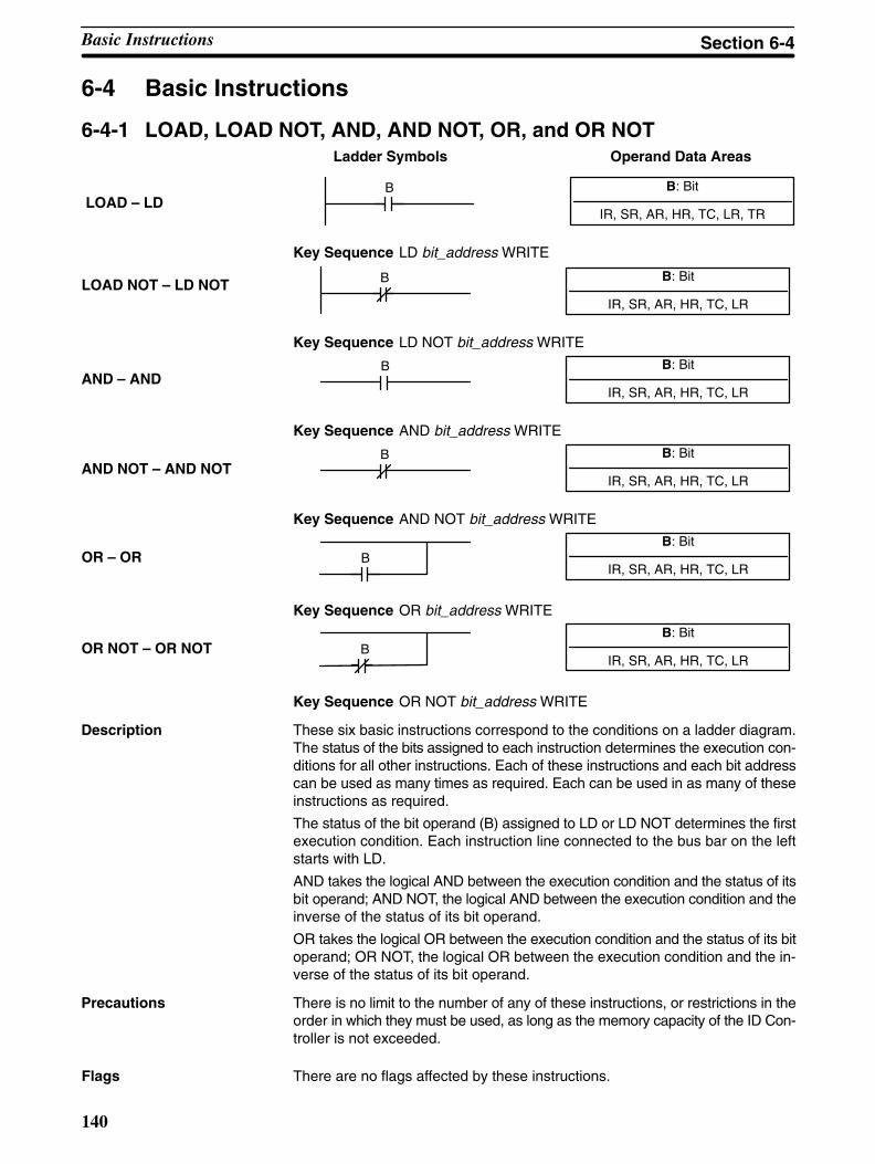
140
6-4 Basic Instructions
6-4-1 LOAD, LOAD NOT, AND, AND NOT, OR, and OR NOT
B: Bit
IR, SR, AR, HR, TC, LR, TR
Ladder Symbols Operand Data Areas
LOAD – LDB
Key Sequence LD bit_address WRITE
B: Bit
IR, SR, AR, HR, TC, LRLOAD NOT – LD NOT B
Key Sequence LD NOT bit_address WRITE
B: Bit
IR, SR, AR, HR, TC, LRAND – AND
B
Key Sequence AND bit_address WRITE
B: Bit
IR, SR, AR, HR, TC, LRAND NOT – AND NOT
B
Key Sequence AND NOT bit_address WRITE
B: Bit
IR, SR, AR, HR, TC, LROR – OR B
Key Sequence OR bit_address WRITE
B: Bit
IR, SR, AR, HR, TC, LROR NOT – OR NOT B
Key Sequence OR NOT bit_address WRITE
These six basic instructions correspond to the conditions on a ladder diagram.The status of the bits assigned to each instruction determines the execution con-ditions for all other instructions. Each of these instructions and each bit addresscan be used as many times as required. Each can be used in as many of theseinstructions as required.
The status of the bit operand (B) assigned to LD or LD NOT determines the firstexecution condition. Each instruction line connected to the bus bar on the leftstarts with LD.
AND takes the logical AND between the execution condition and the status of itsbit operand; AND NOT, the logical AND between the execution condition and theinverse of the status of its bit operand.
OR takes the logical OR between the execution condition and the status of its bitoperand; OR NOT, the logical OR between the execution condition and the in-verse of the status of its bit operand.
There is no limit to the number of any of these instructions, or restrictions in theorder in which they must be used, as long as the memory capacity of the ID Con-troller is not exceeded.
Flags There are no flags affected by these instructions.
Description
Precautions
Basic Instructions Section 6-4
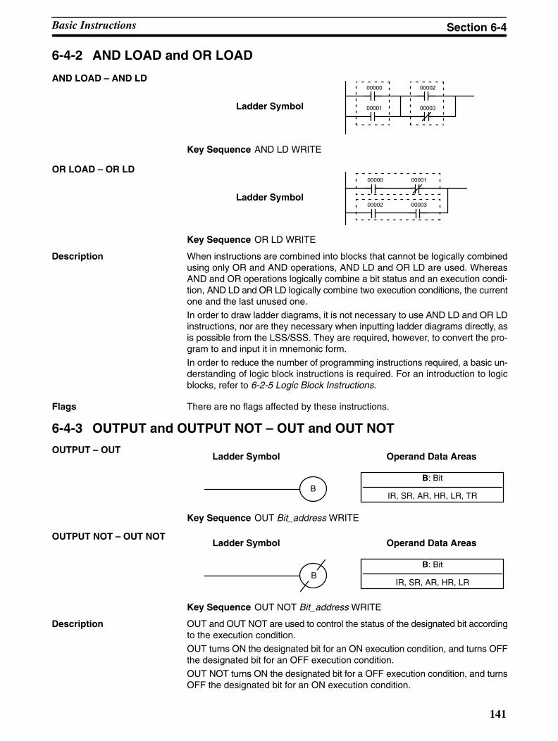
141
6-4-2 AND LOAD and OR LOAD
Ladder Symbol
AND LOAD – AND LD00002
00003
00000
00001
Key Sequence AND LD WRITE
Ladder Symbol
OR LOAD – OR LD00000 00001
00002 00003
Key Sequence OR LD WRITE
When instructions are combined into blocks that cannot be logically combinedusing only OR and AND operations, AND LD and OR LD are used. WhereasAND and OR operations logically combine a bit status and an execution condi-tion, AND LD and OR LD logically combine two execution conditions, the currentone and the last unused one.
In order to draw ladder diagrams, it is not necessary to use AND LD and OR LDinstructions, nor are they necessary when inputting ladder diagrams directly, asis possible from the LSS/SSS. They are required, however, to convert the pro-gram to and input it in mnemonic form.
In order to reduce the number of programming instructions required, a basic un-derstanding of logic block instructions is required. For an introduction to logicblocks, refer to 6-2-5 Logic Block Instructions.
Flags There are no flags affected by these instructions.
6-4-3 OUTPUT and OUTPUT NOT – OUT and OUT NOT
B: Bit
IR, SR, AR, HR, LR, TR
Ladder Symbol Operand Data AreasOUTPUT – OUT
B
Key Sequence OUT Bit_address WRITE
B: Bit
IR, SR, AR, HR, LR
Ladder Symbol Operand Data AreasOUTPUT NOT – OUT NOT
B
Key Sequence OUT NOT Bit_address WRITE
OUT and OUT NOT are used to control the status of the designated bit accordingto the execution condition.
OUT turns ON the designated bit for an ON execution condition, and turns OFFthe designated bit for an OFF execution condition.
OUT NOT turns ON the designated bit for a OFF execution condition, and turnsOFF the designated bit for an ON execution condition.
Description
Description
Basic Instructions Section 6-4
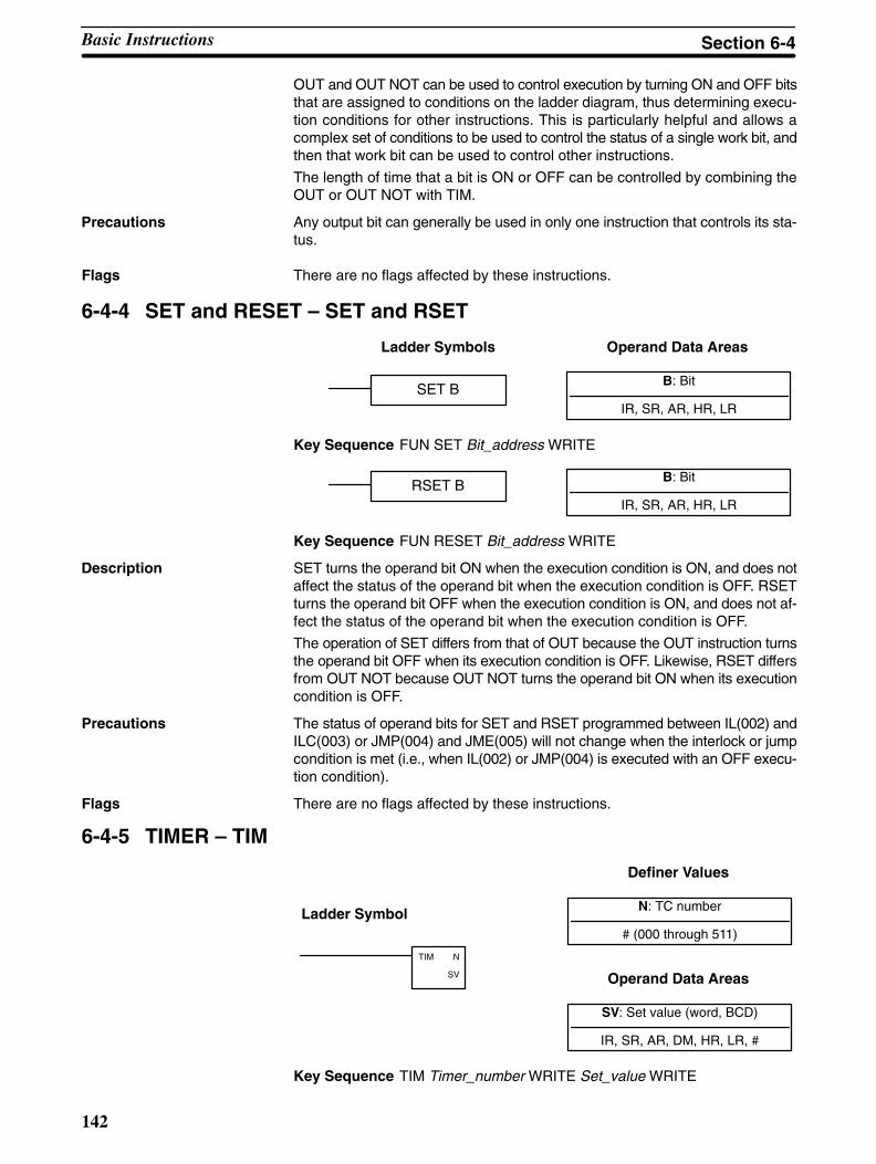
142
OUT and OUT NOT can be used to control execution by turning ON and OFF bitsthat are assigned to conditions on the ladder diagram, thus determining execu-tion conditions for other instructions. This is particularly helpful and allows acomplex set of conditions to be used to control the status of a single work bit, andthen that work bit can be used to control other instructions.
The length of time that a bit is ON or OFF can be controlled by combining theOUT or OUT NOT with TIM.
Any output bit can generally be used in only one instruction that controls its sta-tus.
Flags There are no flags affected by these instructions.
6-4-4 SET and RESET – SET and RSET
B: Bit
IR, SR, AR, HR, LR
Ladder Symbols Operand Data Areas
SET B
Key Sequence FUN SET Bit_address WRITE
B: Bit
IR, SR, AR, HR, LRRSET B
Key Sequence FUN RESET Bit_address WRITE
SET turns the operand bit ON when the execution condition is ON, and does notaffect the status of the operand bit when the execution condition is OFF. RSETturns the operand bit OFF when the execution condition is ON, and does not af-fect the status of the operand bit when the execution condition is OFF.
The operation of SET differs from that of OUT because the OUT instruction turnsthe operand bit OFF when its execution condition is OFF. Likewise, RSET differsfrom OUT NOT because OUT NOT turns the operand bit ON when its executioncondition is OFF.
Precautions The status of operand bits for SET and RSET programmed between IL(002) andILC(003) or JMP(004) and JME(005) will not change when the interlock or jumpcondition is met (i.e., when IL(002) or JMP(004) is executed with an OFF execu-tion condition).
Flags There are no flags affected by these instructions.
6-4-5 TIMER – TIM
N: TC number
# (000 through 511)
Ladder Symbol
Definer Values
SV: Set value (word, BCD)
IR, SR, AR, DM, HR, LR, #
Operand Data Areas
TIM N
SV
Key Sequence TIM Timer_number WRITE Set_value WRITE
Precautions
Description
Basic Instructions Section 6-4

143
A timer is activated when its execution condition goes ON and is reset (to SV)when the execution condition goes OFF. Once activated, TIM measures in unitsof 0.1 second from the SV.If the execution condition remains ON long enough for TIM to time down to zero,the Completion Flag for the TC number used will turn ON and will remain ONuntil TIM is reset (i.e., until its execution condition is goes OFF).The following figure illustrates the relationship between the execution conditionfor TIM and the Completion Flag assigned to it.
Execution condition
Completion Flag
ON
OFF
ON
OFF
SV SV
SV is between 000.0 and 999.9. The decimal point is not entered.Each TC number can be used as the definer in only one TIMER or COUNTERinstruction.TC 000 through TC 015 should not be used in TIM if they are required forTIMH(15). (Refer to the CQM1 Programming Manual for details.)Timers in interlocked program sections are reset when the execution conditionfor IL(02) is OFF. Power interruptions also reset timers. If a timer that is not resetunder these conditions is desired, SR area clock pulse bits can be counted toproduce timers using CNT. Refer to 6-4-6 COUNTER – CNT for details.
Flags ER: SV is not in BCD.
Indirectly addressed DM word is non-existent. (Content of DM word isnot BCD, or the DM area boundary has been exceeded.)
6-4-6 COUNTER – CNT
N: TC number
# (000 through 511)
Ladder Symbol
Definer Values
SV: Set value (word, BCD)
IR, SR, AR, DM, HR, LR, #
Operand Data Areas
CP
R
CNT N
SV
Key Sequence CNT Counter_number WRITE Set_value WRITE
CNT is used to count down from SV when the execution condition on the countpulse, CP, goes from OFF to ON, i.e., the present value (PV) will be decre-mented by one whenever CNT is executed with an ON execution condition forCP and the execution condition was OFF for the last execution. If the executioncondition has not changed or has changed from ON to OFF, the PV of CNT willnot be changed. The Completion Flag for a counter is turned ON when the PVreaches zero and will remain ON until the counter is reset.CNT is reset with a reset input, R. When R goes from OFF to ON, the PV is resetto SV. The PV will not be decremented while R is ON. Counting down from SV willbegin again when R goes OFF. The PV for CNT will not be reset in interlockedprogram sections or by power interruptions.
Description
Precautions
Description
Basic Instructions Section 6-4
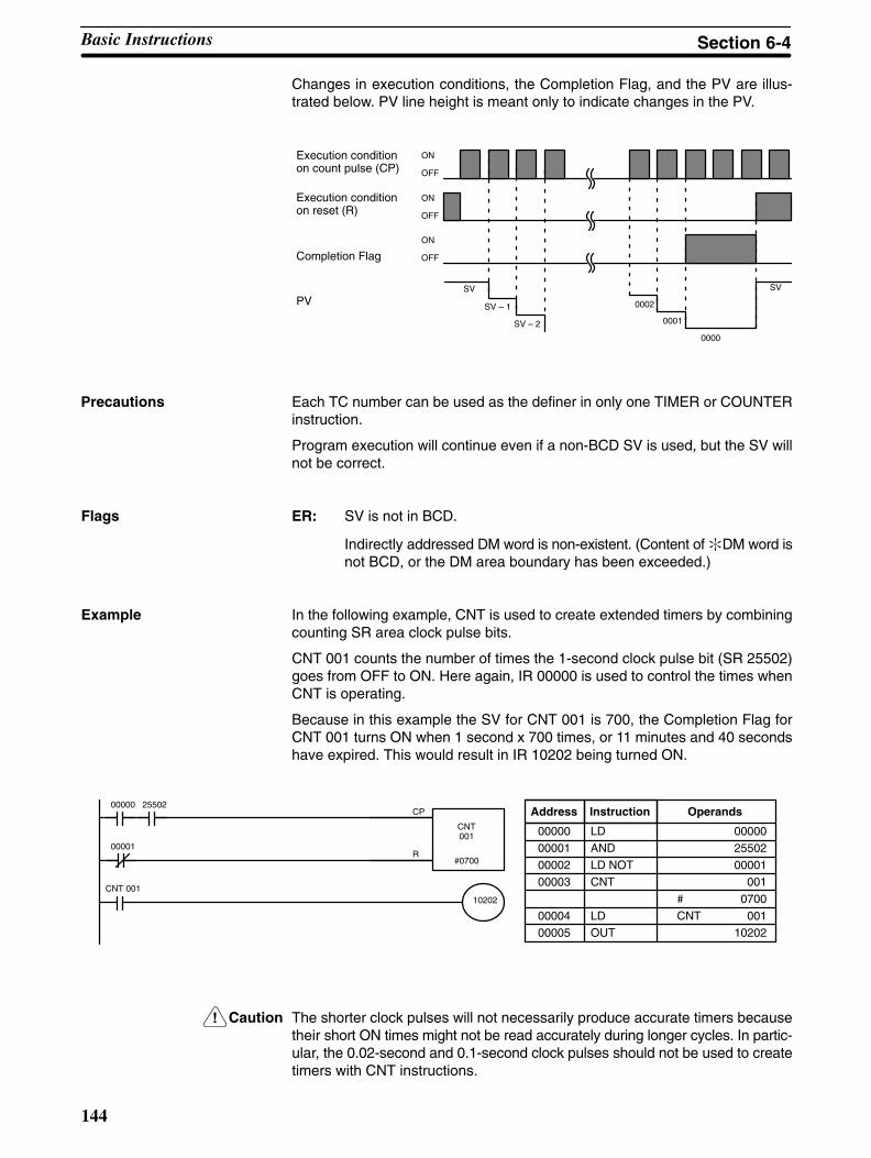
!
144
Changes in execution conditions, the Completion Flag, and the PV are illus-trated below. PV line height is meant only to indicate changes in the PV.
Execution condition on count pulse (CP)
Execution condition on reset (R)
ON
OFF
ON
OFF
Completion FlagON
OFF
PVSV
SV – 1
SV – 2
0002
0001
0000
SV
Each TC number can be used as the definer in only one TIMER or COUNTERinstruction.
Program execution will continue even if a non-BCD SV is used, but the SV willnot be correct.
Flags ER: SV is not in BCD.
Indirectly addressed DM word is non-existent. (Content of DM word isnot BCD, or the DM area boundary has been exceeded.)
Example In the following example, CNT is used to create extended timers by combiningcounting SR area clock pulse bits.
CNT 001 counts the number of times the 1-second clock pulse bit (SR 25502)goes from OFF to ON. Here again, IR 00000 is used to control the times whenCNT is operating.
Because in this example the SV for CNT 001 is 700, the Completion Flag forCNT 001 turns ON when 1 second x 700 times, or 11 minutes and 40 secondshave expired. This would result in IR 10202 being turned ON.
CP
R
CNT001
#0700
00000 25502
00001
CNT 00110202
Address Instruction Operands
00000 LD 00000
00001 AND 25502
00002 LD NOT 00001
00003 CNT 001
# 0700
00004 LD CNT 001
00005 OUT 10202
Caution The shorter clock pulses will not necessarily produce accurate timers becausetheir short ON times might not be read accurately during longer cycles. In partic-ular, the 0.02-second and 0.1-second clock pulses should not be used to createtimers with CNT instructions.
Precautions
Basic Instructions Section 6-4
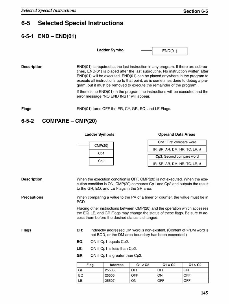
145
6-5 Selected Special Instructions
6-5-1 END – END(01)
Ladder Symbol END(01)
END(01) is required as the last instruction in any program. If there are subrou-tines, END(01) is placed after the last subroutine. No instruction written afterEND(01) will be executed. END(01) can be placed anywhere in the program toexecute all instructions up to that point, as is sometimes done to debug a pro-gram, but it must be removed to execute the remainder of the program.
If there is no END(01) in the program, no instructions will be executed and theerror message “NO END INST” will appear.
Flags END(01) turns OFF the ER, CY, GR, EQ, and LE Flags.
6-5-2 COMPARE – CMP(20)
Cp1: First compare word
IR, SR, AR, DM, HR, TC, LR, #
Cp2: Second compare word
IR, SR, AR, DM, HR, TC, LR, #
Ladder Symbols Operand Data Areas
CMP(20)
Cp1
Cp2
When the execution condition is OFF, CMP(20) is not executed. When the exe-cution condition is ON, CMP(20) compares Cp1 and Cp2 and outputs the resultto the GR, EQ, and LE Flags in the SR area.
When comparing a value to the PV of a timer or counter, the value must be inBCD.
Placing other instructions between CMP(20) and the operation which accessesthe EQ, LE, and GR Flags may change the status of these flags. Be sure to ac-cess them before the desired status is changed.
Flags ER: Indirectly addressed DM word is non-existent. (Content of DM word isnot BCD, or the DM area boundary has been exceeded.)
EQ: ON if Cp1 equals Cp2.
LE: ON if Cp1 is less than Cp2.
GR: ON if Cp1 is greater than Cp2.
Flag Address C1 < C2 C1 = C2 C1 > C2
GR 25505 OFF OFF ON
EQ 25506 OFF ON OFF
LE 25507 ON OFF OFF
Description
Description
Precautions
Selected Special Instructions Section 6-5

146
The following example shows how to save the comparison result immediately. Ifthe content of HR 09 is greater than that of 010, 00200 is turned ON; if the twocontents are equal, 00201 is turned ON; if content of HR 09 is less than that of010, 00202 is turned ON. In some applications, only one of the three OUTs wouldbe necessary, making the use of TR 0 unnecessary. With this type of program-ming, 00200, 00201, and 00202 are changed only when CMP(20) is executed.
CMP(20)
010
HR 09
00000
2550500200
2550700202
TR0
25506
00201
Greater Than
Equal
Less Than
Address Instruction Operands Address Instruction Operands
00000 LD 00000
00001 OUT TR 0
00002 CMP(20)
010
HR 09
00003 LD TR 0
00004 AND 25505
00005 OUT 00200
00006 LD TR 0
00007 AND 25506
00008 OUT 00201
00009 LD TR 0
00010 AND 25507
00011 OUT 00202
6-5-3 MOVE – MOV(21)
S: Source word
IR, SR, AR, DM, HR, TC, LR, #
D: Destination word
IR, SR, AR, DM, HR, LR
Ladder Symbols Operand Data Areas
MOV(21)
S
D
@MOV(21)
S
D
When the execution condition is OFF, MOV(21) is not executed. When the exe-cution condition is ON, MOV(21) copies the content of S to D.
Source word Destination word
Bit status not changed.
Precautions DM 6144 to DM 6655 cannot be used for D.
TC numbers cannot be designated as D to change the PV of the timer or counter.You can, however, easily change the PV of a timer or a counter by usingBSET(71).
Flags ER: Indirectly addressed DM word is non-existent. (Content of DM word isnot BCD, or the DM area boundary has been exceeded.)
EQ: ON when all zeros are transferred to D.
Example: Saving CMP(20) Results
Description
Selected Special Instructions Section 6-5
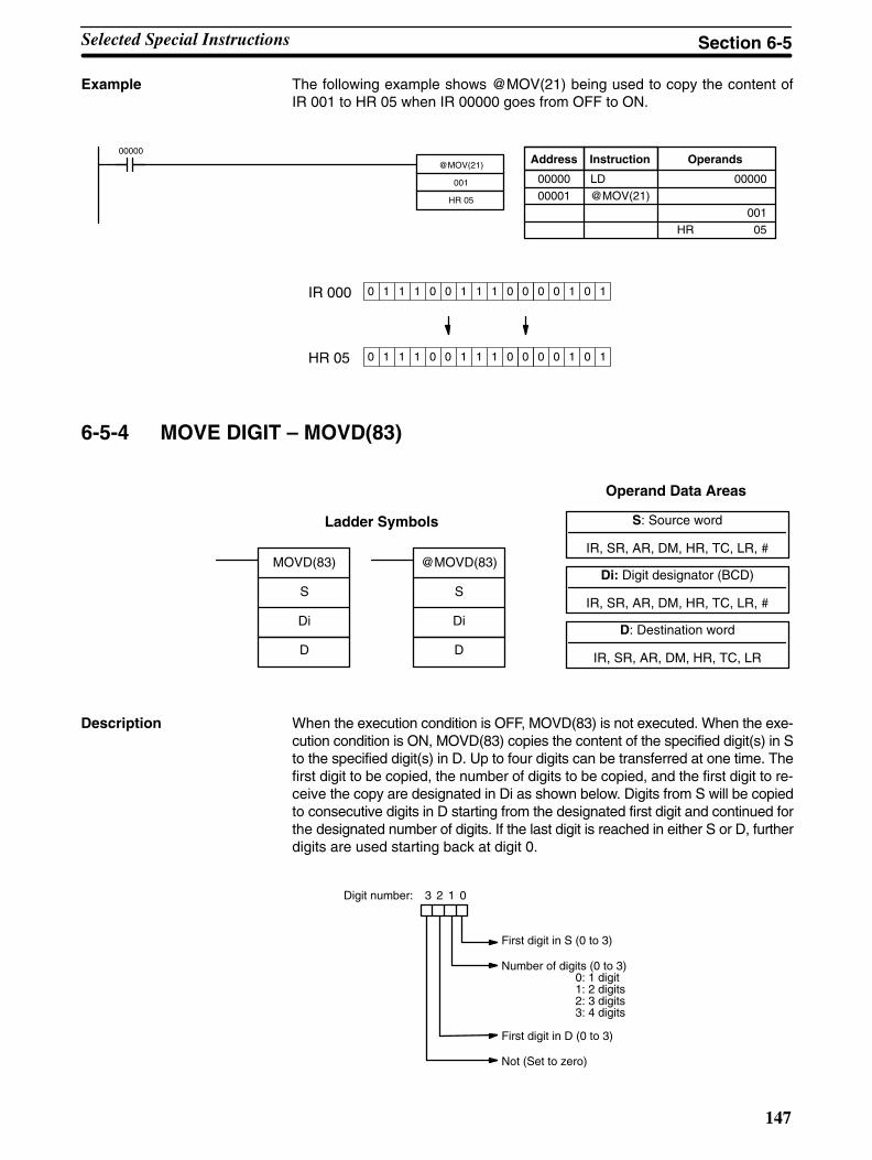
147
Example The following example shows @MOV(21) being used to copy the content ofIR 001 to HR 05 when IR 00000 goes from OFF to ON.
@MOV(21)
001
HR 05
00000Address Instruction Operands
00000 LD 00000
00001 @MOV(21)
001
HR 05
0 1 1 1 0 0 1 1 1 0 0 0 1 0 1HR 05
0 1 1 1 0 0 1 1 1 0 0 0 1 0 1IR 000 0
0
6-5-4 MOVE DIGIT – MOVD(83)
S: Source word
IR, SR, AR, DM, HR, TC, LR, #
Di: Digit designator (BCD)
IR, SR, AR, DM, HR, TC, LR, #
Ladder Symbols
Operand Data Areas
D: Destination word
IR, SR, AR, DM, HR, TC, LR
MOVD(83)
S
Di
D
@MOVD(83)
S
Di
D
When the execution condition is OFF, MOVD(83) is not executed. When the exe-cution condition is ON, MOVD(83) copies the content of the specified digit(s) in Sto the specified digit(s) in D. Up to four digits can be transferred at one time. Thefirst digit to be copied, the number of digits to be copied, and the first digit to re-ceive the copy are designated in Di as shown below. Digits from S will be copiedto consecutive digits in D starting from the designated first digit and continued forthe designated number of digits. If the last digit is reached in either S or D, furtherdigits are used starting back at digit 0.
First digit in S (0 to 3)
Number of digits (0 to 3)0: 1 digit1: 2 digits2: 3 digits3: 4 digits
First digit in D (0 to 3)
Not (Set to zero)
Digit number: 3 2 1 0
Description
Selected Special Instructions Section 6-5

@MOVD(83)
DM 0000
#0201
DM 0003
00000
148
The following show examples of the data movements for various values of Di.
0
1
2
3
0
1
2
3
0
1
2
3
0
1
2
3
S
Di: 0031 Di: 0023
Di: 0030Di: 0010
S
SS
0
1
2
3
D
0
1
2
3
D
0
1
2
3
D
0
1
2
3
D
Precautions The rightmost three digits of Di must each be between 0 and 3.
DM 6144 to DM 6655 cannot be used for Di or D.
Flags ER: At least one of the rightmost three digits of Di is not between 0 and 3.
Indirectly addressed DM word is non-existent. (Content of DM word isnot BCD, or the DM area boundary has been exceeded.)
Example In the following example, MOVD(83) copies the contents of digit 1 (bits 04 to 07)of DM 0000 to digit 2 (bits 08 to 11) of DM 0003 when IR 00000 is ON.
Address Instruction Operands
00000 LD 00000
00001 @MOVD(83)
DM 0000
#0201
DM 0003
103 102 101 100
0 2 0 1
5 6 B A163 162 161 160
B163 162 161 160
Di : #0201
S : DM 0000
D : DM 0003
MSB LSB
Digit 1 in STransfer 1 digitMove to digit 2 in D
Digit Designator
Selected Special Instructions Section 6-5
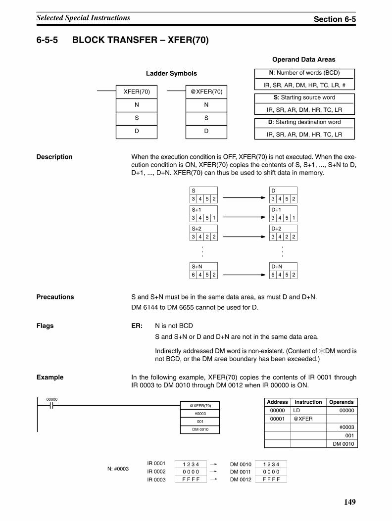
@XFER(70)
#0003
001
DM 0010
00000
149
6-5-5 BLOCK TRANSFER – XFER(70)
N: Number of words (BCD)
IR, SR, AR, DM, HR, TC, LR, #
S: Starting source word
IR, SR, AR, DM, HR, TC, LR
Ladder Symbols
Operand Data Areas
D: Starting destination word
IR, SR, AR, DM, HR, TC, LR
XFER(70)
N
S
D
@XFER(70)
N
S
D
When the execution condition is OFF, XFER(70) is not executed. When the exe-cution condition is ON, XFER(70) copies the contents of S, S+1, ..., S+N to D,D+1, ..., D+N. XFER(70) can thus be used to shift data in memory.
2
D
3 4 5
1
D+1
3 4 5
2
D+2
3 4 2
2
D+N
6 4 5
2
S
3 4 5
1
S+1
3 4 5
2
S+2
3 4 2
2
S+N
6 4 5
S and S+N must be in the same data area, as must D and D+N.
DM 6144 to DM 6655 cannot be used for D.
Flags ER: N is not BCD
S and S+N or D and D+N are not in the same data area.
Indirectly addressed DM word is non-existent. (Content of DM word isnot BCD, or the DM area boundary has been exceeded.)
Example In the following example, XFER(70) copies the contents of IR 0001 throughIR 0003 to DM 0010 through DM 0012 when IR 00000 is ON.
Address Instruction Operands
00000 LD 00000
00001 @XFER
#0003
001
DM 0010
1 2 3 40 0 0 0F F F F
1 2 3 4DM 0010DM 0011
DM 0012
0 0 0 0F F F F
N: #0003IR 0001
IR 0002
IR 0003
Description
Precautions
Selected Special Instructions Section 6-5
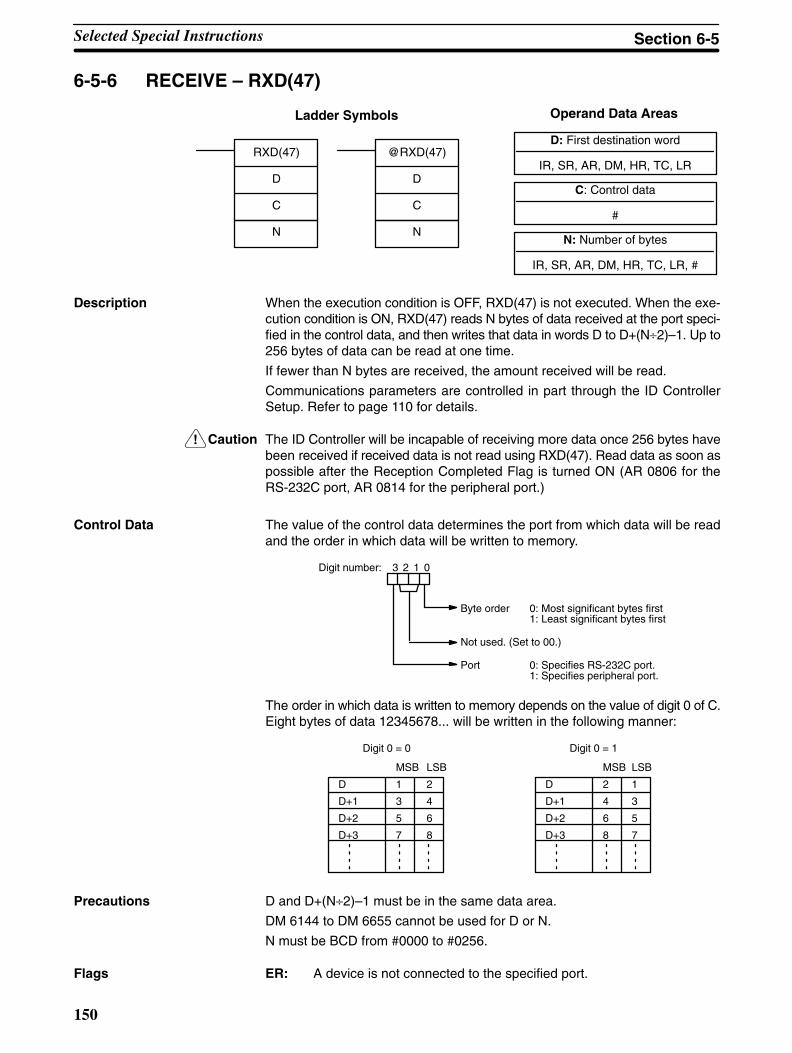
!
150
6-5-6 RECEIVE – RXD(47)
D: First destination word
IR, SR, AR, DM, HR, TC, LR
C: Control data
#
Ladder Symbols Operand Data Areas
N: Number of bytes
IR, SR, AR, DM, HR, TC, LR, #
RXD(47)
D
C
N
@RXD(47)
D
C
N
Description When the execution condition is OFF, RXD(47) is not executed. When the exe-cution condition is ON, RXD(47) reads N bytes of data received at the port speci-fied in the control data, and then writes that data in words D to D+(N÷2)–1. Up to256 bytes of data can be read at one time.
If fewer than N bytes are received, the amount received will be read.
Communications parameters are controlled in part through the ID ControllerSetup. Refer to page 110 for details.
Caution The ID Controller will be incapable of receiving more data once 256 bytes havebeen received if received data is not read using RXD(47). Read data as soon aspossible after the Reception Completed Flag is turned ON (AR 0806 for theRS-232C port, AR 0814 for the peripheral port.)
Control Data The value of the control data determines the port from which data will be readand the order in which data will be written to memory.
Byte order 0: Most significant bytes first1: Least significant bytes first
Not used. (Set to 00.)
Port 0: Specifies RS-232C port.1: Specifies peripheral port.
Digit number: 3 2 1 0
The order in which data is written to memory depends on the value of digit 0 of C.Eight bytes of data 12345678... will be written in the following manner:
MSB LSB
D 1 2
D+1 3 4
D+2 5 6
D+3 7 8
Digit 0 = 0
MSB LSB
D 2 1
D+1 4 3
D+2 6 5
D+3 8 7
Digit 0 = 1
Precautions D and D+(N÷2)–1 must be in the same data area.
DM 6144 to DM 6655 cannot be used for D or N.
N must be BCD from #0000 to #0256.
Flags ER: A device is not connected to the specified port.
Selected Special Instructions Section 6-5
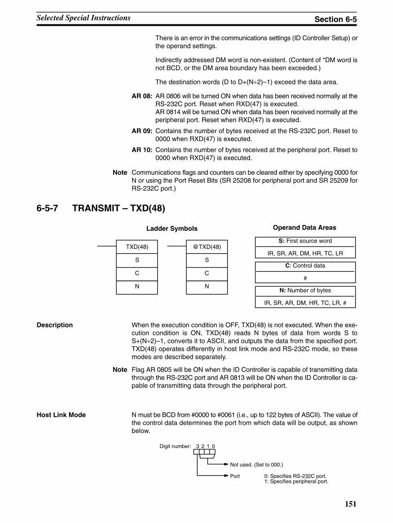
151
There is an error in the communications settings (ID Controller Setup) orthe operand settings.
Indirectly addressed DM word is non-existent. (Content of *DM word isnot BCD, or the DM area boundary has been exceeded.)
The destination words (D to D+(N÷2)–1) exceed the data area.
AR 08: AR 0806 will be turned ON when data has been received normally at theRS-232C port. Reset when RXD(47) is executed.AR 0814 will be turned ON when data has been received normally at theperipheral port. Reset when RXD(47) is executed.
AR 09: Contains the number of bytes received at the RS-232C port. Reset to0000 when RXD(47) is executed.
AR 10: Contains the number of bytes received at the peripheral port. Reset to0000 when RXD(47) is executed.
Note Communications flags and counters can be cleared either by specifying 0000 forN or using the Port Reset Bits (SR 25208 for peripheral port and SR 25209 forRS-232C port.)
6-5-7 TRANSMIT – TXD(48)
S: First source word
IR, SR, AR, DM, HR, TC, LR
C: Control data
#
Ladder Symbols Operand Data Areas
N: Number of bytes
IR, SR, AR, DM, HR, TC, LR, #
TXD(48)
S
C
N
@TXD(48)
S
C
N
Description When the execution condition is OFF, TXD(48) is not executed. When the exe-cution condition is ON, TXD(48) reads N bytes of data from words S toS+(N÷2)–1, converts it to ASCII, and outputs the data from the specified port.TXD(48) operates differently in host link mode and RS-232C mode, so thesemodes are described separately.
Note Flag AR 0805 will be ON when the ID Controller is capable of transmitting datathrough the RS-232C port and AR 0813 will be ON when the ID Controller is ca-pable of transmitting data through the peripheral port.
Host Link Mode N must be BCD from #0000 to #0061 (i.e., up to 122 bytes of ASCII). The value ofthe control data determines the port from which data will be output, as shownbelow.
Not used. (Set to 000.)
Port 0: Specifies RS-232C port.1: Specifies peripheral port.
Digit number: 3 2 1 0
Selected Special Instructions Section 6-5

152
The specified number of bytes will be read from S through S+(N/2)–1, convertedto ASCII, and transmitted through the specified port. The bytes of source datashown below will be transmitted in this order: 12345678...
MSB LSB
S 1 2
S+1 3 4
S+2 5 6
S+3 7 8
The following diagram shows the format for host link command (TXD) sent fromthe ID Controller. The ID Controller automatically attaches the prefixes and suf-fixes, such as the node number, header, and FCS.
@ X X X X X X ......... X X X ∗ CR
Header code
Data (122 ASCII characters max.) FCSNode number
Terminator
RS-232C Mode N must be BCD from #0000 to #00256. The value of the control data determinesthe port from which data will be output and the order in which data will be writtento memory.
Control Data The value of the control data determines the port from which data will be readand the order in which data will be written to memory.
Byte order 0: Most significant bytes first1: Least significant bytes first
Not used. (Set to 00.)
Port 0: Specifies RS-232C port.1: Specifies peripheral port.
Digit number: 3 2 1 0
The specified number of bytes will be read from S through S+(NP2)–1 and trans-mitted through the specified port.
MSB LSB
S 1 2
S+1 3 4
S+2 5 6
S+3 7 8
When digit 0 of C is 0, the bytes of source data shown above will be transmitted inthis order: 12345678...
When digit 0 of C is 1, the bytes of source data shown above will be transmitted inthis order: 21436587...
Note When start and end codes are specified the total data length should be 256 bytesmax., including the start and end codes.
Precautions S and S+(N÷2)–1 must be in the same data area.
DM 6144 to DM 6655 cannot be used for S or N.
N must be BCD from #0000 to #0256. (#0000 to #0061 in host link mode)
Selected Special Instructions Section 6-5

153
Flags ER: A device is not connected to the peripheral port.
There is an error in the communications settings (ID Controller Setup) orthe operand settings.
Indirectly addressed DM word is non-existent. (Content of *DM word isnot BCD, or the DM area boundary has been exceeded.)
The source words (S to S+(N÷2)–1) exceed the data area.
AR 08: AR 0805 will be turned ON when it is possible to transmit through theRS-232C port. AR 0813 will be turned ON when it is possible to transmitthrough the peripheral port.
Selected Special Instructions Section 6-5

155
SECTION 7Programming Examples
This section provides four programming examples using ID communications instructions.
7-1 Recording Data 156. . . . . . . . . . . . . . . . . . . . . . . . . . . . . . . . . . . . . . . . . . . . . . . . . . . . . . . . . . . 7-2 Displaying Worker Instructions 157. . . . . . . . . . . . . . . . . . . . . . . . . . . . . . . . . . . . . . . . . . . . . . 7-3 Managing Production Histories 158. . . . . . . . . . . . . . . . . . . . . . . . . . . . . . . . . . . . . . . . . . . . . . 7-4 Controlling Workpiece Flow 159. . . . . . . . . . . . . . . . . . . . . . . . . . . . . . . . . . . . . . . . . . . . . . . .
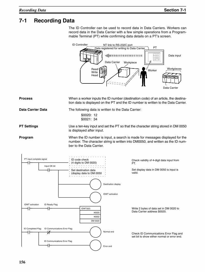
156
7-1 Recording DataThe ID Controller can be used to record data in Data Carriers. Workers canrecord data in the Data Carrier with a few simple operations from a Program-mable Terminal (PT) while confirming data details on a PT’s screen.
ID Controller
Read/WriteHead
Data Carrier Workpiece
Data input
WorkerWorkpieces
Data Carrier
NT link to RS-232C portData registered for writing to Data Carrier PT
Process When a worker inputs the ID number (destination code) of an article, the destina-tion data is displayed on the PT and the ID number is written to the Data Carrier.
Data Carrier Data The following data is written to the Data Carrier:
$0020: 12$0021: 34
PT Settings Use a ten-key input and set the PT so that the character string stored in DM 0050is displayed after input.
Program When the ID number is input, a search is made for messages displayed for thenumber. The character string is written into DM0050, and written as the ID num-ber to the Data Carrier.
Check validity of 4-digit data input fromPT.
Set display data in DM 0050 is input isvalid.
Write 2 bytes of data set in DM 0020 toData Carrier address $0020.
Check ID Communications Error Flag andset bit to show either normal or error end.
ID code check(4 digits to DM 0020)
Set destination data(display data to DM 0050
PT input complete signal
Input OK bit
Destination display
IDWT activation
IDWT activation ID Ready Flag
ID Completed Flag ID Communications Error Flag
ID Communications Error Flag
Normal end
Error end
IDWT(62)
#0020
#0002
DM 0020
Recording Data Section 7-1
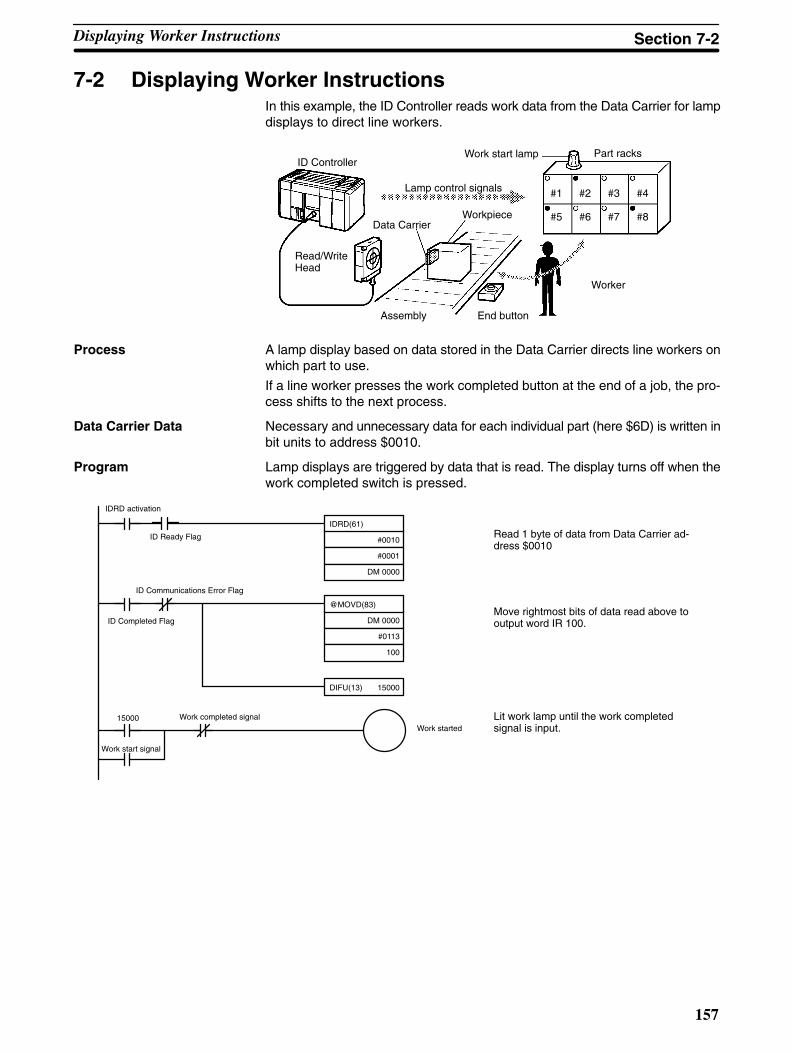
157
7-2 Displaying Worker InstructionsIn this example, the ID Controller reads work data from the Data Carrier for lampdisplays to direct line workers.
ID Controller
Read/Write Head
Data CarrierWorkpiece
Part racks
Worker
Lamp control signals
Assembly End button
Work start lamp
#1 #2 #3 #4
#5 #6 #7 #8
Process A lamp display based on data stored in the Data Carrier directs line workers onwhich part to use.
If a line worker presses the work completed button at the end of a job, the pro-cess shifts to the next process.
Data Carrier Data Necessary and unnecessary data for each individual part (here $6D) is written inbit units to address $0010.
Program Lamp displays are triggered by data that is read. The display turns off when thework completed switch is pressed.
Read 1 byte of data from Data Carrier ad-dress $0010
Move rightmost bits of data read above tooutput word IR 100.
Lit work lamp until the work completedsignal is input.
IDRD activation
ID Ready Flag
ID Completed Flag
ID Communications Error Flag
Work start signal
Work completed signal
IDRD(61)
#0010
#0001
DM 0000
@MOVD(83)
DM 0000
#0113
100
DIFU(13) 15000
15000Work started
Displaying Worker Instructions Section 7-2
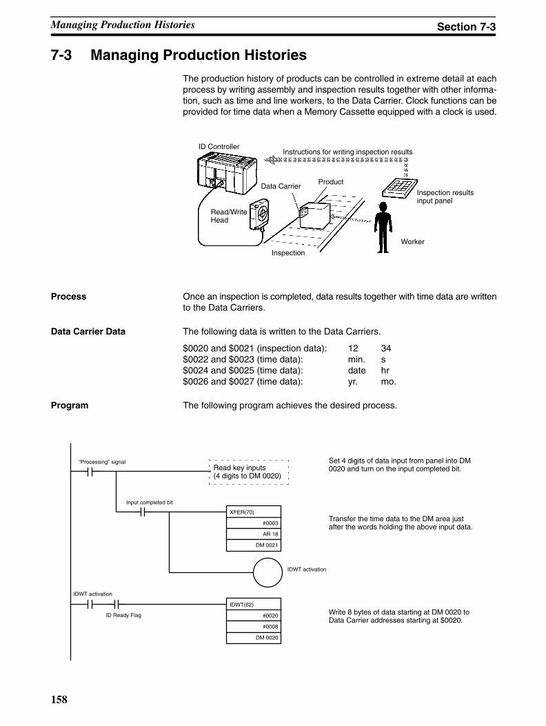
158
7-3 Managing Production HistoriesThe production history of products can be controlled in extreme detail at eachprocess by writing assembly and inspection results together with other informa-tion, such as time and line workers, to the Data Carrier. Clock functions can beprovided for time data when a Memory Cassette equipped with a clock is used.
ID Controller
Read/WriteHead
Data CarrierProduct
Inspection
Worker
Inspection resultsinput panel
Instructions for writing inspection results
Process Once an inspection is completed, data results together with time data are writtento the Data Carriers.
Data Carrier Data The following data is written to the Data Carriers.
$0020 and $0021 (inspection data): 12 34$0022 and $0023 (time data): min. s$0024 and $0025 (time data): date hr$0026 and $0027 (time data): yr. mo.
Program The following program achieves the desired process.
Set 4 digits of data input from panel into DM0020 and turn on the input completed bit.
Transfer the time data to the DM area justafter the words holding the above input data.
Write 8 bytes of data starting at DM 0020 toData Carrier addresses starting at $0020.
Read key inputs(4 digits to DM 0020)
“Processing” signal
Input completed bit
IDWT activation
IDWT activation
ID Ready Flag
XFER(70)
#0003
AR 18
DM 0021
IDWT(62)
#0020
#0008
DM 0020
Managing Production Histories Section 7-3
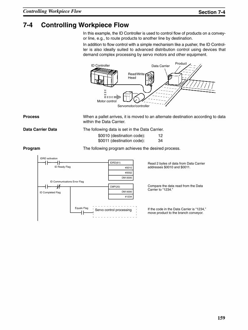
159
7-4 Controlling Workpiece FlowIn this example, the ID Controller is used to control flow of products on a convey-or line, e.g., to route products to another line by destination.
In addition to flow control with a simple mechanism like a pusher, the ID Control-ler is also ideally suited to advanced distribution control using devices thatdemand complex processing by servo motors and other equipment.
ID Controller
Read/WriteHead
Data CarrierProduct
Motor controlServomotor/controller
Process When a pallet arrives, it is moved to an alternate destination according to datawithin the Data Carrier.
Data Carrier Data The following data is set in the Data Carrier.
$0010 (destination code): 12$0011 (destination code): 34
Program The following program achieves the desired process.
Read 2 bytes of data from Data Carrieraddresses $0010 and $0011.
Compare the data read from the DataCarrier to “1234.”
If the code in the Data Carrier is “1234,”move product to the branch conveyor.
Servo control processing
ID Completed Flag
IDRD activation
ID Ready Flag
ID Communications Error Flag
Equals Flag
IDRD(61)
#0010
#0002
DM 0000
CMP(20)
DM 0000
#1234
Controlling Workpiece Flow Section 7-4

161
SECTION 8Internal Processing
This section described the processing that takes place within the ID Controller and explains how to calculate the time requiredfor program execution and related processing (called the scan time).
8-1 Internal Processing 162. . . . . . . . . . . . . . . . . . . . . . . . . . . . . . . . . . . . . . . . . . . . . . . . . . . . . . . . 8-2 Computing the Cycle Time 163. . . . . . . . . . . . . . . . . . . . . . . . . . . . . . . . . . . . . . . . . . . . . . . . . 8-3 Execution Times for ID Communications 165. . . . . . . . . . . . . . . . . . . . . . . . . . . . . . . . . . . . . .
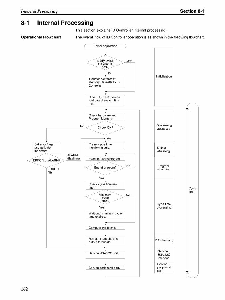
162
8-1 Internal ProcessingThis section explains ID Controller internal processing.
Operational Flowchart The overall flow of ID Controller operation is as shown in the following flowchart.
Power application
Transfer contents ofMemory Cassette to IDController.
Clear IR, SR, AR areasand preset system tim-ers.
Check hardware andProgram Memory.
Check OK?
Preset cycle timemonitoring time.
Execute user’s program.
End of program?
Check cycle time set-ting.
Minimum cycletime?
Wait until minimum cycletime expires.
Compute cycle time.
Refresh input bits andoutput terminals.
Service RS-232C port.
Service peripheral port.
Set error flagsand activateindicators.
ERROR or ALARM?
No
ERROR(lit)
ALARM(flashing)
Initialization
Overseeingprocesses
Programexecution
Cycle timeprocessing
I/O refreshing
ServiceRS-232Cinterface.
Serviceperipheralport.
Cycletime
Is DIP switchpin 2 set to
ON?
OFF
ON
No
Yes
No
Yes
Yes
ID datarefreshing
Internal Processing Section 8-1

163
One cycle of ID Controller operation is called a cycle. The time required for onecycle is called the cycle time. (The cycle time is also called the scan time.)
I/O Refresh Methods ID Controller I/O refresh operations are broadly divided into two categories. Thefirst of these, input refresh, involves reading the ON/OFF status of input points tothe input bits. The second, output refresh, involves writing the ON/OFF statusafter program execution to the output points. The ID Controller I/O refresh meth-ods are as shown in the following table.
Input/Output I/O refresh method FunctionInput Cyclic refresh Input refresh is executed at a set time once per cycle.p
Interrupt input refresh Input refresh is executed before execution of the interrupt processing rou-tine whenever an input interrupt, interval timer interrupt, or high-speedcounter interrupt occurs. (The cyclic refresh is also executed.)
Output Cyclic refresh Output refresh is executed at a set time once per cycle.p
Direct refresh When there is an output from the user’s program, that output point is im-mediately refreshed. (The cyclic refresh is also executed.)
The initial status of the ID Controller I/O refresh is as follows:
Input: Only cyclic refresh executed.Output: Only cyclic refresh executed.
Cyclic refresh must be executed for both inputs and outputs. If input refresh is tobe executed at the time of interrupts, then set the input refresh range in the IDController Setup (DM 6630 to DM 6638). Direct refresh can be set in DM 6639 ofthe ID Controller Setup.
In addition to the methods described above, it is also possible to execute I/O re-freshes in the program by means of IORF(97).
Note Refer to the CQM1 Programming Manual for information on IORF(97).
8-2 Computing the Cycle TimeThis section describes how to calculate ID Controller cycle time.
The processes involved in a single ID Controller cycle are shown in the followingtable, and their respective processing times are explained.
Process Content Time requirements
Overseeing Setting cycle watchdog timer, I/O bus check, UMcheck, refreshing clock, refreshing ID data, etc.
0.9 ms (1.0 ms when a Memory Cas-sette equipped with a clock is mounted)(See note 2.)
Program execution User program is executed. Total time for executing instructions.(Varies according to content of user’sprogram.)
Cycle time calculation Standby until set time, when minimum cycle timeis set in DM 6619 of ID Controller Setup.Calculation of cycle time.
Almost instantaneous, except for stand-by processing.
I/O refresh Input information is read to input bits.
Output information (results of executing program)is written to output points.
0.01 ms
0.005 ms
RS-232C port servicing Devices connected to RS-232C port serviced. 5% or less of cycle time (See note 1.)
Peripheral port servicing Devices connected to peripheral port serviced. 5% or less of cycle time (See note 1.)
Note 1. The percentages can be changed in the ID Controller Setup (DM 6616,DM 6617).
2. If storing ID errors is specified in the ID Controller Setup, the timer requiredfor overseeing operations increases by 0.2 ms during any cycle where an IDerror occurs.
Computing the Cycle Time Section 8-2
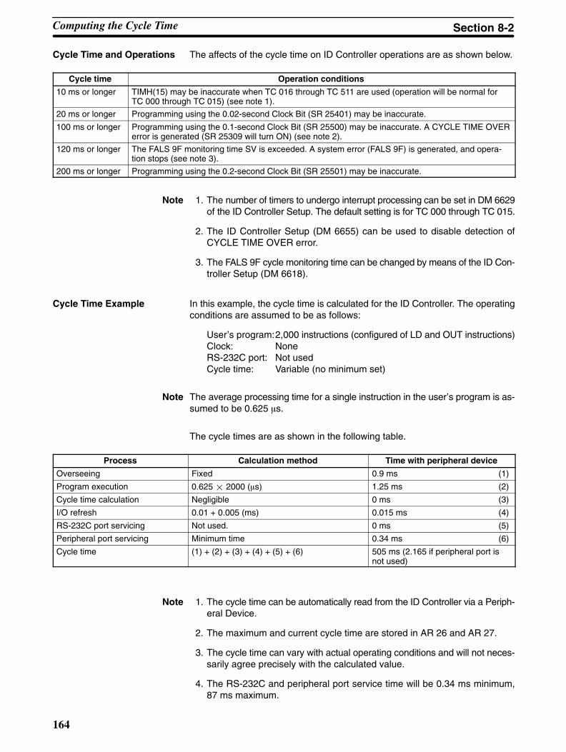
164
Cycle Time and Operations The affects of the cycle time on ID Controller operations are as shown below.
Cycle time Operation conditions
10 ms or longer TIMH(15) may be inaccurate when TC 016 through TC 511 are used (operation will be normal forTC 000 through TC 015) (see note 1).
20 ms or longer Programming using the 0.02-second Clock Bit (SR 25401) may be inaccurate.
100 ms or longer Programming using the 0.1-second Clock Bit (SR 25500) may be inaccurate. A CYCLE TIME OVERerror is generated (SR 25309 will turn ON) (see note 2).
120 ms or longer The FALS 9F monitoring time SV is exceeded. A system error (FALS 9F) is generated, and opera-tion stops (see note 3).
200 ms or longer Programming using the 0.2-second Clock Bit (SR 25501) may be inaccurate.
Note 1. The number of timers to undergo interrupt processing can be set in DM 6629of the ID Controller Setup. The default setting is for TC 000 through TC 015.
2. The ID Controller Setup (DM 6655) can be used to disable detection ofCYCLE TIME OVER error.
3. The FALS 9F cycle monitoring time can be changed by means of the ID Con-troller Setup (DM 6618).
Cycle Time Example In this example, the cycle time is calculated for the ID Controller. The operatingconditions are assumed to be as follows:
User’s program:2,000 instructions (configured of LD and OUT instructions)Clock: NoneRS-232C port: Not usedCycle time: Variable (no minimum set)
Note The average processing time for a single instruction in the user’s program is as-sumed to be 0.625 s.
The cycle times are as shown in the following table.
Process Calculation method Time with peripheral device
Overseeing Fixed 0.9 ms (1)
Program execution 0.625 2000 (s) 1.25 ms (2)
Cycle time calculation Negligible 0 ms (3)
I/O refresh 0.01 + 0.005 (ms) 0.015 ms (4)
RS-232C port servicing Not used. 0 ms (5)
Peripheral port servicing Minimum time 0.34 ms (6)
Cycle time (1) + (2) + (3) + (4) + (5) + (6) 505 ms (2.165 if peripheral port isnot used)
Note 1. The cycle time can be automatically read from the ID Controller via a Periph-eral Device.
2. The maximum and current cycle time are stored in AR 26 and AR 27.
3. The cycle time can vary with actual operating conditions and will not neces-sarily agree precisely with the calculated value.
4. The RS-232C and peripheral port service time will be 0.34 ms minimum,87 ms maximum.
Computing the Cycle Time Section 8-2

165
8-3 Execution Times for ID Communications
This section shows how to calculate the TAT (turn-around time) for ID Controllercommunications. The TAT is the time from when a communications instruction isexecuted in the ladder-diagram program until a response is received.
ID Communications The is always some what of a delay between executing an ID communicationsinstruction, communicating with a Data Carrier, and receiving the results back tothe ID Controller. This time, called the TAT, varies with the specifications for theID communications instruction and the operating conditions of the ID Controllerwhen the instruction is executed. The following diagram illustrates a generalizedcase.
Cycle time
ID Ready Flag(SR 23300)
ID Completed Flag (SR 23301)
ID Controllerprocessing
Instruction execution Instruction execution Instruction execution
ID communications timeRefresh delay
For cyclicrefreshes
For interruptrefreshes
ID communications instruction executed
Calculations for Cycle RefreshesTAT = Instruction execution time + ID communications time + refresh delay
(Refresh delay = 1 cycle maximum)
Calculations for Interrupt Refreshes RefreshesTAT = Instruction execution time + ID communications time + interrupt overhead
The interrupt overhead is the time required to activate the interrupt subroutineand is 0.1 ms for any ID communication instructions plus 0.3 ms to store readdata for IDRD(61) and IDAR(63)
Instruction Execution Times This following table lists the execution times for ID communications instructions.The maximum and minimum execution times and the conditions which causethem are given where relevant. When “word” is referred to in the Conditions col-umn, it implies the content of any word except for indirectly addressed DMwords. Indirectly addressed DM words, which create longer execution timeswhen used, are indicated by “DM.”
Refer to the CQM1 Programming Manual for execution times for other instruc-tions.
Code Mnemonic Executiontime (µs)
Conditions (minimum times first; maximum last)
61 IDRD 131.75 Constants for first two operands; word forthird.
135.75 Words for all three operands.
216.75 DM for all three operands
Execution Times for ID Communications Section 8-3

166
Code Conditions (minimum times first; maximum last)
Executiontime (µs)
Mnemonic
62 IDWT 135.75 Constants for first two operands; word forthird. Writing one byte, normal order.
146.75 Words for all three operands. Writing onebyte, normal order.
149.75 Words for all three operands. Writing onebyte, reversing order.
213.75 DM for all three operands. Writing onebyte, normal order.
146.75 Constants for first two operands; word forthird. Writing ten bytes, normal order.
157.75 Words for all three operands. Writing tenbytes, normal order.
160.75 Words for all three operands. Writing tenbytes, reversing order.
224.75 DM for all three operands. Writing tenbytes, normal order.
433.75 Constants for first two operands; word forthird. Writing 256 bytes, normal order.
457.75 Words for all three operands. Writing 256bytes, normal order.
534.75 Words for all three operands. Writing 256bytes, reversing order.
530.75 DM for all three operands. Writing 256bytes, normal order.
63 IDAR 131.75 Constants for first two operands; word forthird.
132.75 Words for all three operands.
212.75 DM for all three operands
64 IDAW 134.75 Constants for first two operands; word forthird. Reading one byte, normal order.
146.75 Words for all three operands. Reading onebyte, normal order.
149.75 Words for all three operands. Reading onebyte, reversing order.
213.75 DM for all three operands. Reading onebyte, normal order.
145.75 Constants for first two operands; word forthird. Reading ten bytes, normal order.
156.75 Words for all three operands. Reading tenbytes, normal order.
160.75 Words for all three operands. Reading tenbytes, reversing order.
224.75 DM for all three operands. Reading tenbytes, normal order.
456.75 Constants for first two operands; word forthird. Reading 256 bytes, normal order.
458.75 Words for all three operands. Reading 256bytes, normal order.
536.75 Words for all three operands. Reading 256bytes, reversing order.
550.75 DM for all three operands. Reading 256bytes, normal order.
Execution Times for ID Communications Section 8-3
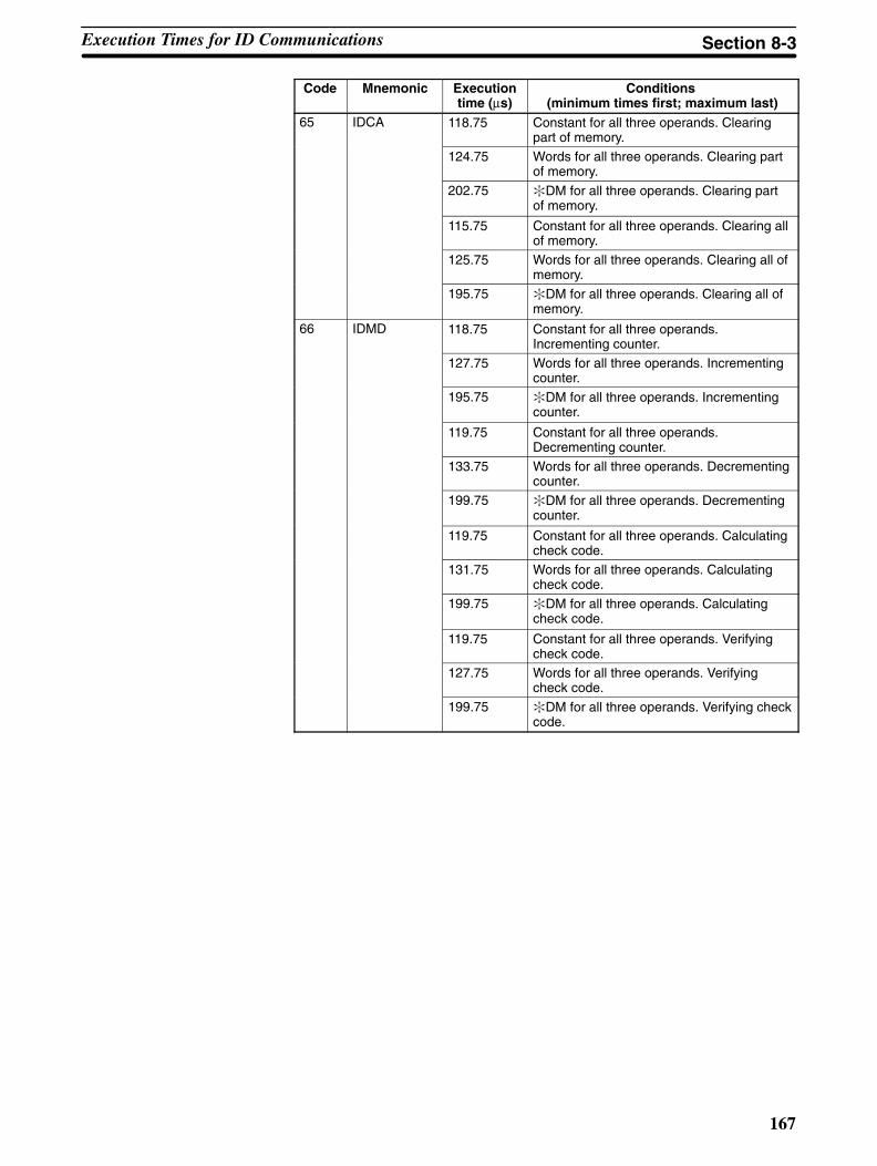
167
Code Conditions (minimum times first; maximum last)
Executiontime (µs)
Mnemonic
65 IDCA 118.75 Constant for all three operands. Clearingpart of memory.
124.75 Words for all three operands. Clearing partof memory.
202.75 DM for all three operands. Clearing partof memory.
115.75 Constant for all three operands. Clearing allof memory.
125.75 Words for all three operands. Clearing all ofmemory.
195.75 DM for all three operands. Clearing all ofmemory.
66 IDMD 118.75 Constant for all three operands.Incrementing counter.
127.75 Words for all three operands. Incrementingcounter.
195.75 DM for all three operands. Incrementingcounter.
119.75 Constant for all three operands.Decrementing counter.
133.75 Words for all three operands. Decrementingcounter.
199.75 DM for all three operands. Decrementingcounter.
119.75 Constant for all three operands. Calculatingcheck code.
131.75 Words for all three operands. Calculatingcheck code.
199.75 DM for all three operands. Calculatingcheck code.
119.75 Constant for all three operands. Verifyingcheck code.
127.75 Words for all three operands. Verifyingcheck code.
199.75 DM for all three operands. Verifying checkcode.
Execution Times for ID Communications Section 8-3
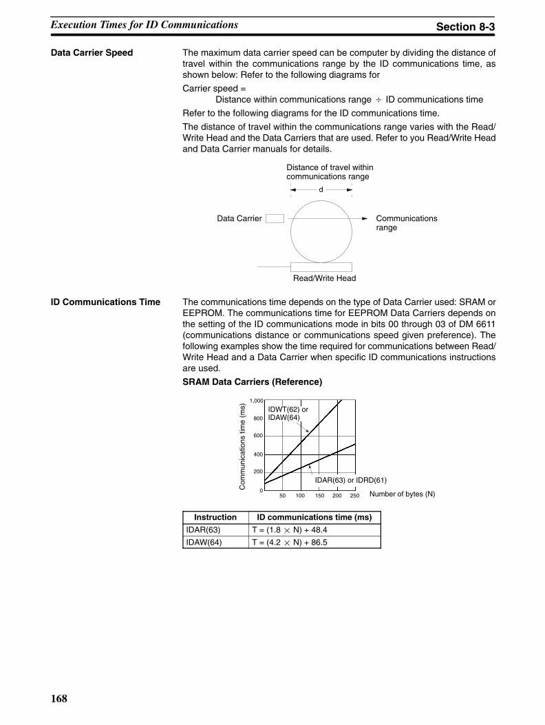
168
Data Carrier Speed The maximum data carrier speed can be computer by dividing the distance oftravel within the communications range by the ID communications time, asshown below: Refer to the following diagrams for
Carrier speed = Distance within communications range ID communications time
Refer to the following diagrams for the ID communications time.
The distance of travel within the communications range varies with the Read/Write Head and the Data Carriers that are used. Refer to you Read/Write Headand Data Carrier manuals for details.
Distance of travel withincommunications range
Data Carrier Communicationsrange
Read/Write Head
d
ID Communications Time The communications time depends on the type of Data Carrier used: SRAM orEEPROM. The communications time for EEPROM Data Carriers depends onthe setting of the ID communications mode in bits 00 through 03 of DM 6611(communications distance or communications speed given preference). Thefollowing examples show the time required for communications between Read/Write Head and a Data Carrier when specific ID communications instructionsare used.
SRAM Data Carriers (Reference)
Number of bytes (N)
Com
mun
icat
ions
tim
e (m
s)
1,000
800
600
400
200
050 100 150 200 250
IDAR(63) or IDRD(61)
IDWT(62) orIDAW(64)
Instruction ID communications time (ms)
IDAR(63) T = (1.8 N) + 48.4
IDAW(64) T = (4.2 N) + 86.5
Execution Times for ID Communications Section 8-3

169
EEPROM Data Carriers, Priority to Communications Distance (Reference)
Number of bytes (N)Com
mun
icat
ions
tim
e (m
s)
2,000
1,500
1,000
500
0100 200 300
IDAR(63) or IDRD(61)
IDWT(62) orIDAW(64)
Instruction ID communications time (ms)
IDAR(63) T = (4.3 N) + 64.6
IDAW(64) T = (8.7 N) + 167.1
EEPROM Data Carriers, Priority to Communications Speed (Reference)
Number of bytes (N)
Com
mun
icat
ions
tim
e (m
s)
2,000
1,500
1,000
500
0100 200 300
IDAR(63) or IDRD(61)
IDWT(62) orIDAW(64)
Instruction ID communications time (ms)
IDAR(63) T = (1.8 N) + 79.0
IDAW(64) T = (7.1 N) + 180.4
Execution Times for ID Communications Section 8-3
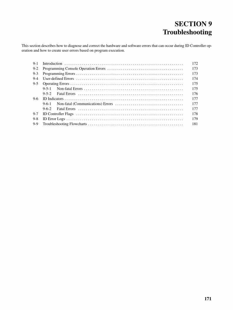
171
SECTION 9Troubleshooting
This section describes how to diagnose and correct the hardware and software errors that can occur during ID Controller op-eration and how to create user errors based on program execution.
9-1 Introduction 172. . . . . . . . . . . . . . . . . . . . . . . . . . . . . . . . . . . . . . . . . . . . . . . . . . . . . . . . . . . . . 9-2 Programming Console Operation Errors 173. . . . . . . . . . . . . . . . . . . . . . . . . . . . . . . . . . . . . . . 9-3 Programming Errors 173. . . . . . . . . . . . . . . . . . . . . . . . . . . . . . . . . . . . . . . . . . . . . . . . . . . . . . . 9-4 User-defined Errors 174. . . . . . . . . . . . . . . . . . . . . . . . . . . . . . . . . . . . . . . . . . . . . . . . . . . . . . . 9-5 Operating Errors 175. . . . . . . . . . . . . . . . . . . . . . . . . . . . . . . . . . . . . . . . . . . . . . . . . . . . . . . . . .
9-5-1 Non-fatal Errors 175. . . . . . . . . . . . . . . . . . . . . . . . . . . . . . . . . . . . . . . . . . . . . . . . . . . 9-5-2 Fatal Errors 176. . . . . . . . . . . . . . . . . . . . . . . . . . . . . . . . . . . . . . . . . . . . . . . . . . . . . .
9-6 ID Indicators 177. . . . . . . . . . . . . . . . . . . . . . . . . . . . . . . . . . . . . . . . . . . . . . . . . . . . . . . . . . . . . 9-6-1 Non-fatal (Communications) Errors 177. . . . . . . . . . . . . . . . . . . . . . . . . . . . . . . . . . . 9-6-2 Fatal Errors 177. . . . . . . . . . . . . . . . . . . . . . . . . . . . . . . . . . . . . . . . . . . . . . . . . . . . . .
9-7 ID Controller Flags 178. . . . . . . . . . . . . . . . . . . . . . . . . . . . . . . . . . . . . . . . . . . . . . . . . . . . . . . 9-8 ID Error Logs 179. . . . . . . . . . . . . . . . . . . . . . . . . . . . . . . . . . . . . . . . . . . . . . . . . . . . . . . . . . . . 9-9 Troubleshooting Flowcharts 181. . . . . . . . . . . . . . . . . . . . . . . . . . . . . . . . . . . . . . . . . . . . . . . . .
172
9-1 Introduction
ID Controller errors can be divided broadly into the following four categories:
1, 2, 3... 1. Program Input Errors
These errors occur when inputting a program or attempting an operationused to prepare the ID Controller for operation.
2. Programming Errors
These errors will occur when the program is checked using the ProgramCheck operation.
3. User-defined Errors
There are three instructions that the user can use to define his own errors ormessages. The instructions will be executed when a particular condition(defined by the user) has occurred during operation.
4. Operating Errors
These errors occur after program execution has been started.
a) Non-fatal Operating ErrorsID Controller operation and program execution will continue after one ormore of these errors have occurred.
b) Fatal Operating ErrorsID Controller operation and program execution will stop and all outputsfrom the ID Controller will be turned OFF when any of these errors haveoccurred.
The ID Controller’s indicators will indicate when a ID Controller error has oc-curred and an error message or code will be displayed on the ProgrammingConsole or host computer if one is connected. The error code is also containedin SR 25300 to SR 25307.
For the most recent errors, both the type of error and time of occurrence will berecorded in an error log area (DM 6570 to DM 6599). Details are provided start-ing on page 110.
There are flags and other information provided in the SR and AR Areas that canbe used in troubleshooting.
Note Errors can also occur in ID functions and Host Link functions. ID errors can betroubleshot through the ID indicators on the ID Controller or through ID Control-ler flags in memory. ID errors are described later in this sections. Refer to theCQM1 Programming Manual for details on Host Link errors.
Introduction Section 9-1

173
9-2 Programming Console Operation ErrorsThe following error messages may appear when performing operations on theProgramming Console. Correct the error as indicated and continue with the op-eration. The asterisks in the displays shown below will be replaced with numericdata, normally an address, in the actual display. Refer to the operation manualfor your programming device or software for errors that may appear for it.
Message Meaning and appropriate response
REPL ROM An attempt was made to write to write-protected memory. Set thewrite-protect switch (pin 1 of the ID Controller’s DIP switch) to OFF.
PROG OVER The instruction at the last address in memory is not NOP(00). Eraseall unnecessary instructions at the end of the program.
ADDR OVER An address was set that is larger than the highest memory addressin Program Memory. Input a smaller address.
SETDATAERR
FALS 00 has been input, and “00” cannot be input. Reinput thedata.
I/O NO. ERR A data area address has been designated that exceeds the limit ofthe data area, e.g., an address is too large. Confirm therequirements for the instruction and re-enter the address.
9-3 Programming ErrorsThese errors in program syntax will be detected when the program is checkedusing the Program Check operation.
Three levels of program checking are available. The desired level must be des-ignated to indicate the type of errors that are to be detected. The following tableprovides the error types, displays, and explanations of all syntax errors. Checklevel 0 checks for type A, B, and C errors; check level 1, for type A and B errors;and check level 2, for type A errors only.
Message Meaning and appropriate response
????? The program has been damaged, creating a non-existent functioncode. Re-enter the program.
CIRCUITERR
The number of logic blocks and logic block instructions does notagree, i.e., either LD or LD NOT has been used to start a logicblock whose execution condition has not been used by anotherinstruction, or a logic block instruction has been used that does nothave the required number of logic blocks. Check your program.
OPERANDERR
A constant entered for the instruction is not within defined values.Change the constant so that it lies within the proper range.
NO ENDINSTR
There is no END(01) in the program. Write END(01) at the finaladdress in the program.
LOCN ERR An instruction is in the wrong place in the program. Checkinstruction requirements and correct the program.
JMEUNDEFD
A JME(04) instruction is missing for a JMP(05) instruction. Correctthe jump number or insert the proper JME(04) instruction.
DUPL The same jump number or subroutine number has been used twice.Correct the program so that the same number is only used once foreach.
SBNUNDEFD
The SBS(91) instruction has been programmed for a subroutinenumber that does not exist. Correct the subroutine number orprogram the required subroutine.
STEP ERR STEP(08) with a section number and STEP(08) without a sectionnumber have been used incorrectly. Check STEP(08) programmingrequirements and correct the program.
Level A Errors
Programming Errors Section 9-3

!
174
Message Meaning and appropriate response
IL-ILC ERR IL(02) and ILC(03) are not used in pairs. Correct the program sothat each IL(02) has a unique ILC(03). Although this error messagewill appear if more than one IL(02) is used with the same ILC(03),the program will executed as written. Make sure your program iswritten as desired before proceeding.
JMP-JMEERR
JMP(04) 00 and JME(05) 00 are not used in pairs. Although thiserror message will appear if more than one JMP(04) 00 is used withthe same JME(05) 00, the program will be executed as written.Make sure your program is written as desired before proceeding.
SBN-RETERR
If the displayed address is that of SBN(92), two differentsubroutines have been defined with the same subroutine number.Change one of the subroutine numbers or delete one of thesubroutines. If the displayed address is that of RET(93), RET(93)has not been used properly. Check requirements for RET(93) andcorrect the program.
Message Meaning and appropriate response
COIL DUPL The same bit is being controlled (i.e., turned ON and/or OFF) bymore than one instruction (e.g., OUT, OUT NOT, DIFU(13),DIFD(14), KEEP(11), SFT(10)). Although this is allowed for certaininstructions, check instruction requirements to confirm that theprogram is correct or rewrite the program so that each bit iscontrolled by only one instruction.
JMPUNDEFD
JME(05) has been used with no JMP(04) with the same jumpnumber. Add a JMP(04) with the same number or delete theJME(05) that is not being used.
SBSUNDEFD
A subroutine exists that is not called by SBS(91). Program asubroutine call in the proper place, or delete the subroutine if it isnot required.
Caution Expansion instructions (those assigned to function codes 17, 18, 19, 47, 48, 60to 69, 87, 88, and 89) are not subject to program checks.
9-4 User-defined ErrorsThere are three instructions that the user can use to define his own errors ormessages. These instructions are used to send messages to the ProgrammingConsole connected to the ID Controller and cause a non-fatal or a fatal error.
MESSAGE – MSG(46) MSG(46) is used to display a message on the Programming Console. The mes-sage, which can be up to 16 characters long, is displayed when the instruction’sexecution condition is ON.
FAL(06) is an instruction that causes a non-fatal error. The following will occurwhen an FAL(06) instruction is executed:
1, 2, 3... 1. The ERR/ALM indicator on the ID Controller will flash. ID Controller opera-tion will continue.
2. The instruction’s 2-digit BCD FAL number (01 to 99) will be written toSR 25300 to SR 25307.
3. The FAL number and time of occurrence will be recorded in the ID Control-ler’s error log area if a Memory Cassette with a clock (RTC) is used.
The FAL numbers can be set arbitrarily to indicate particular conditions. Thesame number cannot be used as both an FAL number and an FALS number.To clear an FAL error, correct the cause of the error, execute FAL 00, and thenclear the error using the Programming Console.
FALS(07) is an instruction that causes a fatal error. The following will occur whenan FALS(07) instruction is executed:
1, 2, 3... 1. Program execution will be stopped and outputs will be turned OFF.
Level B Errors
Level C Errors
FAILURE ALARM – FAL(06)
SEVERE FAILURE ALARM –FALS(07)
User-defined Errors Section 9-4
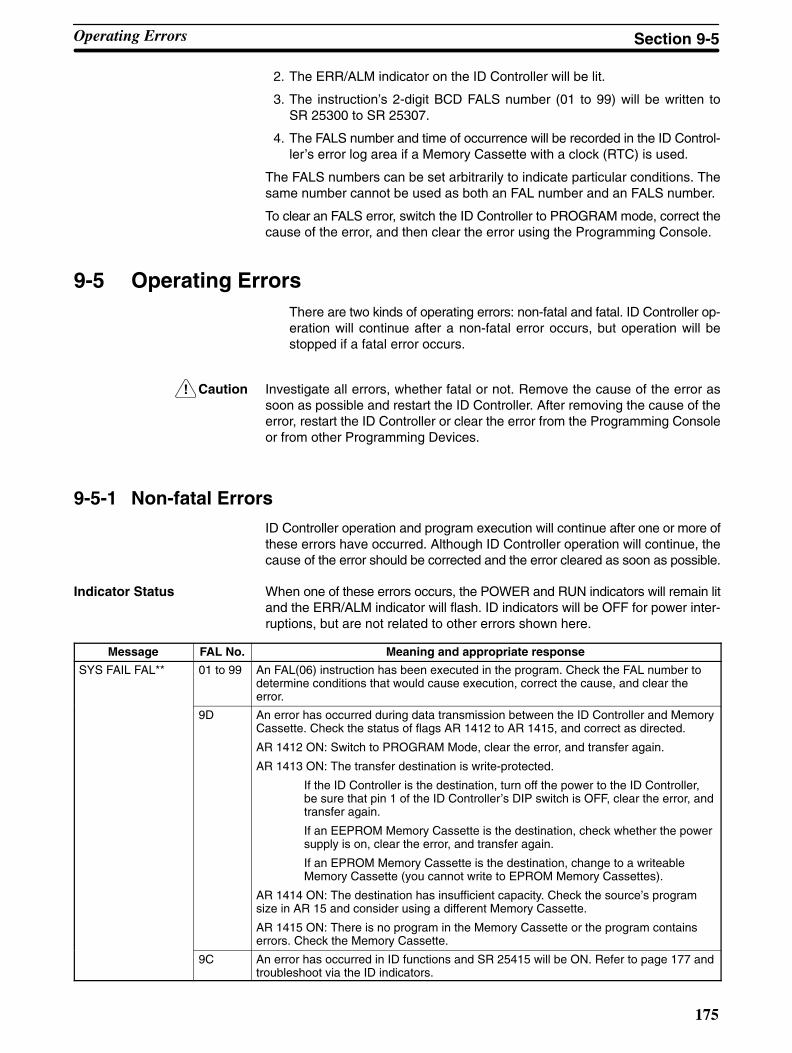
!
175
2. The ERR/ALM indicator on the ID Controller will be lit.
3. The instruction’s 2-digit BCD FALS number (01 to 99) will be written toSR 25300 to SR 25307.
4. The FALS number and time of occurrence will be recorded in the ID Control-ler’s error log area if a Memory Cassette with a clock (RTC) is used.
The FALS numbers can be set arbitrarily to indicate particular conditions. Thesame number cannot be used as both an FAL number and an FALS number.
To clear an FALS error, switch the ID Controller to PROGRAM mode, correct thecause of the error, and then clear the error using the Programming Console.
9-5 Operating ErrorsThere are two kinds of operating errors: non-fatal and fatal. ID Controller op-eration will continue after a non-fatal error occurs, but operation will bestopped if a fatal error occurs.
Caution Investigate all errors, whether fatal or not. Remove the cause of the error assoon as possible and restart the ID Controller. After removing the cause of theerror, restart the ID Controller or clear the error from the Programming Consoleor from other Programming Devices.
9-5-1 Non-fatal Errors
ID Controller operation and program execution will continue after one or more ofthese errors have occurred. Although ID Controller operation will continue, thecause of the error should be corrected and the error cleared as soon as possible.
Indicator Status When one of these errors occurs, the POWER and RUN indicators will remain litand the ERR/ALM indicator will flash. ID indicators will be OFF for power inter-ruptions, but are not related to other errors shown here.
Message FAL No. Meaning and appropriate response
SYS FAIL FAL** 01 to 99 An FAL(06) instruction has been executed in the program. Check the FAL number todetermine conditions that would cause execution, correct the cause, and clear theerror.
9D An error has occurred during data transmission between the ID Controller and MemoryCassette. Check the status of flags AR 1412 to AR 1415, and correct as directed.
AR 1412 ON: Switch to PROGRAM Mode, clear the error, and transfer again.
AR 1413 ON: The transfer destination is write-protected.
If the ID Controller is the destination, turn off the power to the ID Controller,be sure that pin 1 of the ID Controller’s DIP switch is OFF, clear the error, andtransfer again.
If an EEPROM Memory Cassette is the destination, check whether the powersupply is on, clear the error, and transfer again.
If an EPROM Memory Cassette is the destination, change to a writeableMemory Cassette (you cannot write to EPROM Memory Cassettes).
AR 1414 ON: The destination has insufficient capacity. Check the source’s programsize in AR 15 and consider using a different Memory Cassette.
AR 1415 ON: There is no program in the Memory Cassette or the program containserrors. Check the Memory Cassette.
9C An error has occurred in ID functions and SR 25415 will be ON. Refer to page 177 andtroubleshoot via the ID indicators.
Operating Errors Section 9-5
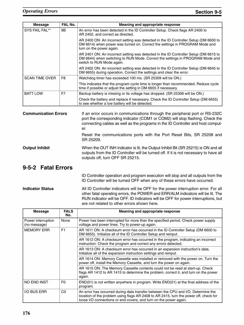
176
Message Meaning and appropriate responseFAL No.
SYS FAIL FAL** 9B An error has been detected in the ID Controller Setup. Check flags AR 2400 toAR 2402, and correct as directed.
AR 2400 ON: An incorrect setting was detected in the ID Controller Setup (DM 6600 toDM 6614) when power was turned on. Correct the settings in PROGRAM Mode andturn on the power again.
AR 2401 ON: An incorrect setting was detected in the ID Controller Setup (DM 6615 toDM 6644) when switching to RUN Mode. Correct the settings in PROGRAM Mode andswitch to RUN Mode again.
AR 2402 ON: An incorrect setting was detected in the ID Controller Setup (DM 6645 toDM 6655) during operation. Correct the settings and clear the error.
SCAN TIME OVER F8 Watchdog timer has exceeded 100 ms. (SR 25309 will be ON.)
This indicates that the program cycle time is longer than recommended. Reduce cycletime if possible or adjust the setting in DM 6655 if necessary.
BATT LOW F7 Backup battery is missing or its voltage has dropped. (SR 25308 will be ON.)
Check the battery and replace if necessary. Check the ID Controller Setup (DM 6655)to see whether a low battery will be detected.
Communication Errors If an error occurs in communications through the peripheral port or RS-232Cport the corresponding indicator (COM1 or COM2) will stop flashing. Check theconnecting cables as well as the programs in the ID Controller and host comput-er.
Reset the communications ports with the Port Reset Bits, SR 25208 andSR 25209.
Output Inhibit When the OUT INH indicator is lit, the Output Inhibit Bit (SR 25215) is ON and alloutputs from the ID Controller will be turned off. If it is not necessary to have alloutputs off, turn OFF SR 25215.
9-5-2 Fatal ErrorsID Controller operation and program execution will stop and all outputs from theID Controller will be turned OFF when any of these errors have occurred.
Indicator Status All ID Controller indicators will be OFF for the power interruption error. For allother fatal operating errors, the POWER and ERR/ALM indicators will be lit. TheRUN indicator will be OFF. ID indicators will be OFF for power interruptions, butare not related to other errors shown here.
Message FALSNo.
Meaning and appropriate response
Power interruption(no message)
None Power has been interrupted for more than the specified period. Check power supplyvoltage and power lines. Try to power-up again.
MEMORY ERR F1 AR 1611 ON: A checksum error has occurred in the ID Controller Setup (DM 6600 toDM 6655). Initialize all of the ID Controller Setup and reinput.
AR 1612 ON: A checksum error has occurred in the program, indicating an incorrectinstruction. Check the program and correct any errors detected.
AR 1613 ON: A checksum error has occurred in an expansion instruction’s data.Initialize all of the expansion instruction settings and reinput.
AR 1614 ON: Memory Cassette was installed or removed with the power on. Turn thepower off, install the Memory Cassette, and turn the power on again.
AR 1615 ON: The Memory Cassette contents could not be read at start-up. Checkflags AR 1412 to AR 1415 to determine the problem, correct it, and turn on the poweragain.
NO END INST F0 END(01) is not written anywhere in program. Write END(01) at the final address of theprogram.
I/O BUS ERR C0 An error has occurred during data transfer between the CPU and I/O. Determine thelocation of the problem using flags AR 2408 to AR 2415, turn the power off, check forloose I/O connections or end covers, and turn on the power again.
Operating Errors Section 9-5

!
177
Message Meaning and appropriate responseFALSNo.
SYS FAIL FALS**(see note)
01 to 99 An FALS(07) instruction has been executed in the program. Check the FALS numberto determine the conditions that would cause execution, correct the cause, and clearthe error.
9F The cycle time has exceeded the FALS 9F Cycle Time Monitoring Time (DM 6618).Check the cycle time and adjust the Cycle Time Monitoring Time if necessary.
9-6 ID IndicatorsThere are two kinds of ID errors: non-fatal (communications errors) and fa-tal. ID functions will continue after a non-fatal error occurs, but ID functionswill be stopped if a fatal error occurs. ID Controller program execution andother operation will continue even for fatal ID errors.
Caution Investigate all errors, whether fatal or not. Remove the cause of the error assoon as possible and restart the ID Controller. After removing the cause of theerror, restart the ID Controller or clear the error from the Programming Consoleor from other Programming Devices.
9-6-1 Non-fatal (Communications) ErrorsGeneral ID Controller operation and ID functions will continue after one or moreof these errors have occurred. Although operation will continue, the cause of theerror should be corrected and the error cleared as soon as possible.
ID Function Indicator Status RDY: LitERR: FlashingT/R: Not litThe status of other indicators is not relevant.
Message FALSNo.
Meaning and appropriate response
ID COMM ERR 7 An error has occurred in communications with the Data Carrier. SR 23302 will be ONand the nature of the error will be indicated in one of the flags between SR 23308 andSR 23313.
The program should be written to execute retries. If communications errors continue,there may be problems in the system or system devices. Investigate the error and takeappropriate actions.
9-6-2 Fatal ErrorsAlthough general ID Controller operation will continue, ID functions will stopwhen any of these errors have occurred.
Indicator Status ERR/ALM: Flashing RDY: Not lit The status of other indicators is not relevant.
Message FAL No. Meaning and appropriate response
SYS FAIL FAL** 9C An error has occurred in ID functions and SR 25415 will be ON. If an watchdog timererror occurred, the content of AR 04 will be 01.
Turn the power to the ID Controller off and then back on.
Indicator Status ERR/ALM: Flashing RDY: Lit The status of other indicators is not relevant.
Message FAL No. Meaning and appropriate response
SYS FAIL FAL** 9C An error has occurred in ID functions and SR 25415 will be ON. If an memory errorhas occurred, the content of AR 04 will be 02.
Turn the power to the ID Controller off and then back on.
ID Indicators Section 9-6

178
Indicator Status ERR/ALM: Flashing RDY: Lit ERR: LitThe status of other indicators is not relevant.
Message FAL No. Meaning and appropriate response
SYS FAIL FAL** 9C AR 04 = 03
There is an error in the ID Controller Setup relating to ID functions.
Correct the settings in PROGRAM mode and turn the power to the ID Controller offand then back on.
AR 04 = 04
The operating mode was changed while communicating with the Read/Write Head.
Turn the power to the ID Controller off and then back on, or clear the error and changethe operating mode.
9-7 ID Controller FlagsID Communications Errors SR 23302 (ID Communications Error Flag) will turn ON if an error occurs in ID
communications. When this happens, the following flags can be used to trouble-shoot the cause of the error. The following errors are recorded in the ID Control-ler and can be read out using a Programming Console.
Bit Name (code) ON when Action
SR 23308 DC Missing Error Flag (72) There is no Data Carrier in thecommunications range.
Check the installation distances andprogram execution timing.
SR 23309 Write Protected Error Flag (7D) A write was specified for aprotected area.
Release the memory protection orchange the write address.
SR 23310 DC Communications Error Flag(70)
An error occurred incommunications with the DataCarrier.
Check for noise, check the DataCarrier speed, and check installationdistances.
SR 23311 Address Error Flag (7A) An illegal address wasspecified.
Check the address setting to be sureit is within range. If IDMD(66) is beingexecuted, check address accordingto instruction specifications.
SR 23312 Verification Error Flag (71) A write or read operation wasnot completed normally.
Check for noise.
SR 23313 No Head Error Flag (7C) A Read/Write Head is notconnected.
Connect a Read/Write Head.
ID Communications Warnings The following flags will turn ON to indicate various warnings even when ID com-munications have been completed normally. These errors are not recorded inthe ID Controller.
Bit Name ON when Action
SR 23306 DC Battery Warning Flag The voltage of the battery builtinto the Data Carrier is low,indicating the battery haspassed its service life.
Replace the Data Carrier battery or, ifthe battery is not replaceable, replacethe Data Carrier.
SR 23307 ID Check Warning Flag An error is detected for theIDMD(66) (ID CHECK)instruction.
If write count management was beingused, either change the write area orreplace the Data Carrier.
If a check code was being verified,either the life of the Data Carrier hasexpired or it is not being used underproper conditions. Check operatingconditions and replace the DataCarrier if its life has expired.
Note SR 23307 (ID Check Warning Flag) will also turn ON if the IDMD(66) is not usedcorrectly. Be sure to correctly operands carefully when writing or update thewrite count, when writing the check code, and when specifying check areawords.
ID Controller Flags Section 9-7
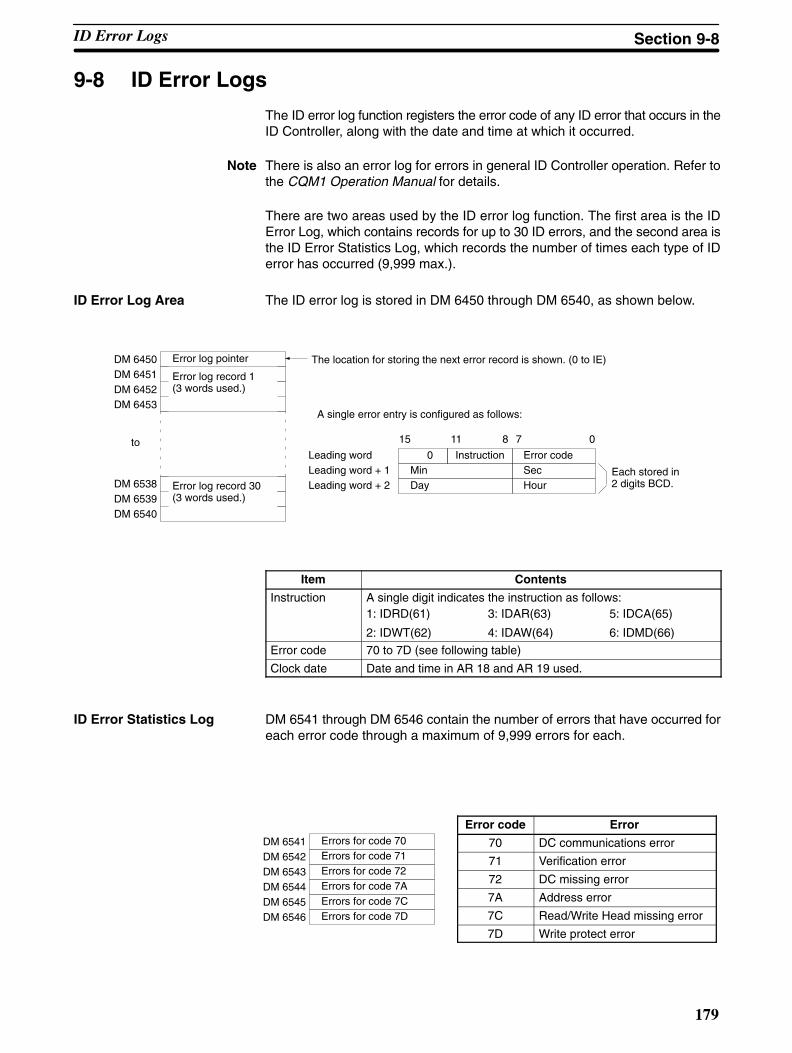
179
9-8 ID Error Logs
The ID error log function registers the error code of any ID error that occurs in theID Controller, along with the date and time at which it occurred.
Note There is also an error log for errors in general ID Controller operation. Refer tothe CQM1 Operation Manual for details.
There are two areas used by the ID error log function. The first area is the IDError Log, which contains records for up to 30 ID errors, and the second area isthe ID Error Statistics Log, which records the number of times each type of IDerror has occurred (9,999 max.).
ID Error Log Area The ID error log is stored in DM 6450 through DM 6540, as shown below.
DM 6450 Error log pointer
DM 6451 Error log record 1(3 words used.)DM 6452
DM 6453
DM 6538 Error log record 30(3 words used.)DM 6539
DM 6540
toInstruction Error code
Min SecDay Hour
Leading wordLeading word + 1Leading word + 2
The location for storing the next error record is shown. (0 to IE)
Each stored in2 digits BCD.
15 8 7 0
A single error entry is configured as follows:
0
11
Item Contents
Instruction A single digit indicates the instruction as follows:1: IDRD(61)
2: IDWT(62)
3: IDAR(63)
4: IDAW(64)
5: IDCA(65)
6: IDMD(66)
Error code 70 to 7D (see following table)
Clock date Date and time in AR 18 and AR 19 used.
ID Error Statistics Log DM 6541 through DM 6546 contain the number of errors that have occurred foreach error code through a maximum of 9,999 errors for each.
Error code Error
70 DC communications error
71 Verification error
72 DC missing error
7A Address error
7C Read/Write Head missing error
7D Write protect error
DM 6541 Errors for code 70
DM 6542 Errors for code 71
DM 6543 Errors for code 72
DM 6544 Errors for code 7A
DM 6545 Errors for code 7C
DM 6546 Errors for code 7D
ID Error Logs Section 9-8
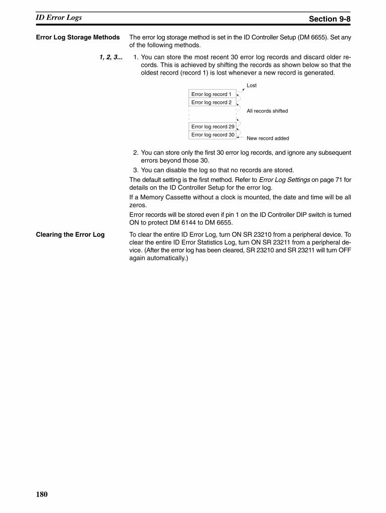
180
Error Log Storage Methods The error log storage method is set in the ID Controller Setup (DM 6655). Set anyof the following methods.
1, 2, 3... 1. You can store the most recent 30 error log records and discard older re-cords. This is achieved by shifting the records as shown below so that theoldest record (record 1) is lost whenever a new record is generated.
Error log record 29
Error log record 30
Error log record 1
Error log record 2
Lost
New record added
All records shifted
2. You can store only the first 30 error log records, and ignore any subsequenterrors beyond those 30.
3. You can disable the log so that no records are stored.
The default setting is the first method. Refer to Error Log Settings on page 71 fordetails on the ID Controller Setup for the error log.
If a Memory Cassette without a clock is mounted, the date and time will be allzeros.
Error records will be stored even if pin 1 on the ID Controller DIP switch is turnedON to protect DM 6144 to DM 6655.
Clearing the Error Log To clear the entire ID Error Log, turn ON SR 23210 from a peripheral device. Toclear the entire ID Error Statistics Log, turn ON SR 23211 from a peripheral de-vice. (After the error log has been cleared, SR 23210 and SR 23211 will turn OFFagain automatically.)
ID Error Logs Section 9-8
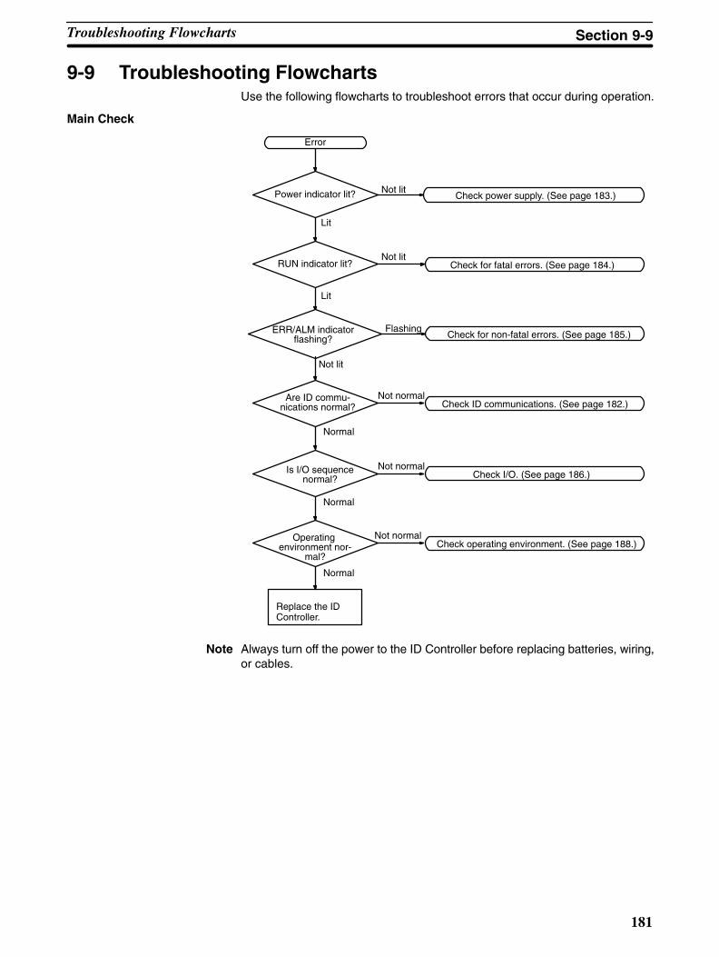
181
9-9 Troubleshooting FlowchartsUse the following flowcharts to troubleshoot errors that occur during operation.
Main Check
Check for non-fatal errors. (See page 185.)
Error
Replace the IDController.
Power indicator lit?
RUN indicator lit?
ERR/ALM indicatorflashing?
Are ID commu-nications normal?
Operating environment nor-
mal?
Check for fatal errors. (See page 184.)
Check ID communications. (See page 182.)
Check operating environment. (See page 188.)
Lit
Check power supply. (See page 183.)Not lit
Not normal
Not lit
Not normal
Flashing
Normal
Normal
Not lit
Lit
Is I/O sequencenormal? Check I/O. (See page 186.)
Not normal
Normal
Note Always turn off the power to the ID Controller before replacing batteries, wiring,or cables.
Troubleshooting Flowcharts Section 9-9

182
I/O Communications Check Before starting the following flowchart, connect a Programming Console andread the ID error history.
No
No errors?
E70?
Start
DC speed OK? Installationdirections OK?
Reduce the speed ofthe Data Carrier.
No
Data CarrierOK?
No
Yes Yes Yes
No
Yes
Yes
No
Correct installation dis-tances, direction, etc.
Replace Data Carrier.
E71? Data CarrierOK?
Replace Data Carrier.
NoNo
Yes Yes
E7A? Page and ad-dresses OK?
Reset the page andaddresses.
NoNo
Yes Yes
E7C? Read/WriteHead OK?
Replace Read/WriteHead.
NoNo
Yes Yes
E7D? Write protectsetting OK?
Data CarrierOK?
Correct (release) writeprotect setting.
NoNo
Yes YesYes
No
Replace Data Carrier.
E72?Distance
between R/WHead and DC
OK?
Data CarrierOK?
Correct distance.
NoNo
Yes YesYes
No
Replace Data Carrier.
End Replace ID Controller.
Troubleshooting Flowcharts Section 9-9
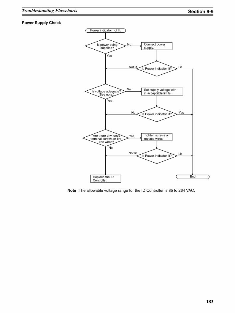
183
Power Supply Check
Power indicator not lit.
Replace the IDController.
Is power beingsupplied?
Is voltage adequate?(See note.)
Are there any looseterminal screws or bro-
ken wires?
Connect powersupply.
Is Power indicator lit?
Set supply voltage with-in acceptable limits.
Is Power indicator lit?
Tighten screws orreplace wires.
End
Yes
No
Not lit Lit
YesNo
No
Not litIs Power indicator lit?
Lit
No
Yes
Yes
Note The allowable voltage range for the ID Controller is 85 to 264 VAC.
Troubleshooting Flowcharts Section 9-9

184
Fatal Error Check The following flowchart can be used to troubleshoot fatal errors that occur whilethe Power indicator is lit.
Identify the error, eliminateits cause, and clear the er-ror.
Is the ERR/ALMindicator lit?
Determine the causeof the error with aPeripheral Device.
End
RUN indicator not lit.
Replace the IDController.
Is ID Controller modedisplayed on Peripher-
al Device?
Correct the powersupply.
Switch to RUN orMONITOR mode.
No
Yes
Is a fatal errordisplayed?
Is ID Controller modedisplayed on Peripher-
al Device?
No
Yes
Yes
No
Is the ERR/ALMindicator lit?
No
Yes
Troubleshooting Flowcharts Section 9-9
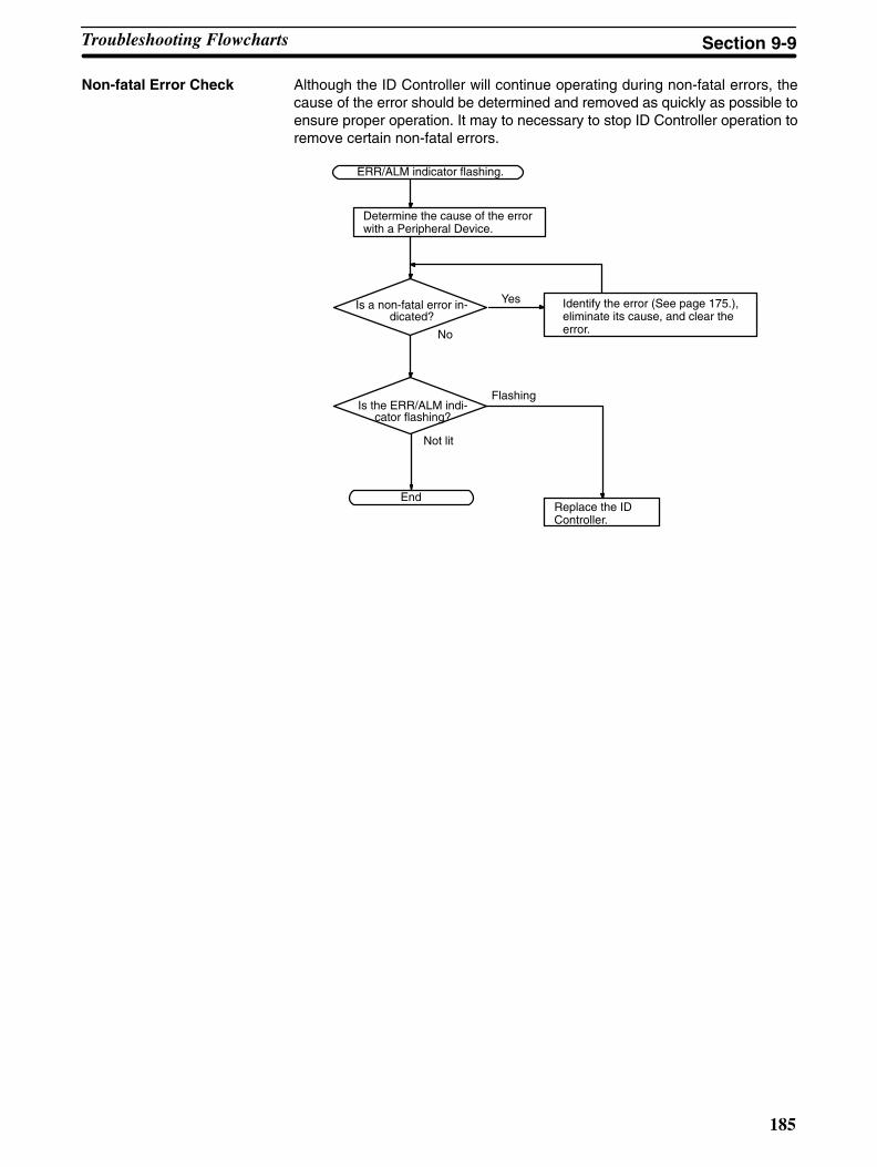
185
Non-fatal Error Check Although the ID Controller will continue operating during non-fatal errors, thecause of the error should be determined and removed as quickly as possible toensure proper operation. It may to necessary to stop ID Controller operation toremove certain non-fatal errors.
Identify the error (See page 175.),eliminate its cause, and clear theerror.
ERR/ALM indicator flashing.
Is a non-fatal error in-dicated?
Is the ERR/ALM indi-cator flashing?
Replace the IDController.
End
Determine the cause of the errorwith a Peripheral Device.
No
Yes
Flashing
Not lit
Troubleshooting Flowcharts Section 9-9
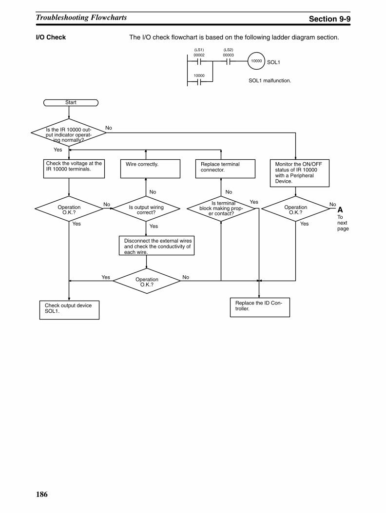
186
I/O Check The I/O check flowchart is based on the following ladder diagram section.
10000
00002(LS1)
00003(LS2)
SOL1 malfunction.
SOL1
10000
Yes
Monitor the ON/OFFstatus of IR 10000with a Peripheral Device.
NoIs the IR 10000 out-put indicator operat-
ing normally?
Check the voltage at theIR 10000 terminals.
Wire correctly. Replace terminalconnector.
OperationO.K.?
Start
Is output wiringcorrect?
Is terminalblock making prop-
er contact?
Disconnect the external wiresand check the conductivity ofeach wire.
No
Yes
Check output deviceSOL1.
OperationO.K.?
Replace the ID Con-troller.
Yes
No
No
Yes No
OperationO.K.?
NoYes
Yes
ATonextpage
Troubleshooting Flowcharts Section 9-9
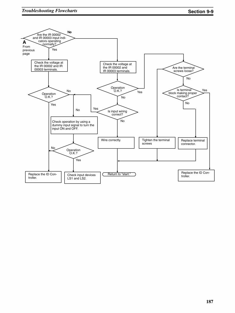
187
Yes
No
Check the voltage atthe IR 00002 and IR00003 terminals.
Check operation by using adummy input signal to turn theinput ON and OFF.
No
Replace the ID Con-troller.
Are the terminalscrews loose?
OperationO.K.?
Wire correctly.
Is input wiringcorrect?
Tighten the terminalscrews
Replace terminalconnector.
Is terminalblock making proper
contact?
Check input devicesLS1 and LS2.
Return to “start.”
Are the IR 00002and IR 00003 input indi-
cators operatingnormally?
OperationO.K.?
Replace the ID Con-troller.
OperationO.K.?
Yes
Yes
Yes
Yes
NoNo
No
No
No
No
No
Yes
No
Check the voltage atthe IR 00002 andIR 00003 terminals.
AFrompreviouspage
Troubleshooting Flowcharts Section 9-9
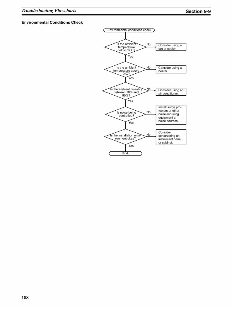
188
Environmental Conditions Check
Consider using afan or cooler.
Environmental conditions check
Is the ambienttemperaturebelow 55°C?
Is the ambienttemperature above
0°C?
Is noise beingcontrolled?
Is the installation envi-ronment okay?
Consider using aheater.
Consider using anair conditioner.
Install surge pro-tectors or othernoise-reducingequipment atnoise sources.
Considerconstructing aninstrument panelor cabinet.
End.
Yes
No
Yes
No
No
No
No
Yes
Yes
Yes
Is the ambient humiditybetween 10% and
90%?
Troubleshooting Flowcharts Section 9-9
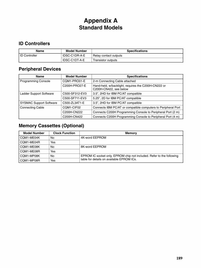
189
Appendix AStandard Models
ID ControllersName Model Number Specifications
ID Controller IDSC-C1DR-A-E Relay contact outputs
IDSC-C1DT-A-E Transistor outputs
Peripheral DevicesName Model Number Specifications
Programming Console CQM1-PRO01-E 2-m Connecting Cable attached
C200H-PRO27-E Hand-held, w/backlight; requires the C200H-CN222 orC200H-CN422, see below
Ladder Support Software C500-SF312-EV3 3.5”, 2HD for IBM PC/AT compatible
C500-SF711-EV3 5.25”, 2D for IBM PC/AT compatible
SYSMAC Support Software C500-ZL3AT1-E 3.5”, 2HD for IBM PC/AT compatible
Connecting Cable CQM1-CIF02 Connects IBM PC/AT or compatible computers to Peripheral Port
C200H-CN222 Connects C200H Programming Console to Peripheral Port (2 m)
C200H-CN422 Connects C200H Programming Console to Peripheral Port (4 m)
Memory Cassettes (Optional)Model Number Clock Function Memory
CQM1-ME04K No 4K-word EEPROM
CQM1-ME04R Yes
CQM1-ME08K No 8K-word EEPROM
CQM1-ME08R Yes
CQM1-MP08K No EPROM IC socket only. EPROM chip not included. Refer to the followingbl f d il il bl EPROM ICCQM1-MP08R Yes
y p gtable for details on available EPROM ICs.
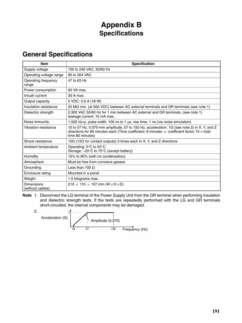
191
Appendix BSpecifications
General SpecificationsItem Specification
Supply voltage 100 to 240 VAC, 50/60 Hz
Operating voltage range 85 to 264 VAC
Operating frequencyrange
47 to 63 Hz
Power consumption 60 VA max.
Inrush current 30 A max.
Output capacity 5 VDC: 3.6 A (18 W)
Insulation resistance 20 M min. (at 500 VDC) between AC external terminals and GR terminals (see note 1)
Dielectric strength 2,300 VAC 50/60 Hz for 1 min between AC external and GR terminals, (see note 1) leakage current: 10 mA max.
Noise immunity 1,500 Vp-p, pulse width: 100 ns to 1 s, rise time: 1 ns (via noise simulation)
Vibration resistance 10 to 57 Hz, 0.075-mm amplitude, 57 to 150 Hz, acceleration: 1G (see note 2) in X, Y, and Zdirections for 80 minutes each (Time coefficient; 8 minutes coefficient factor 10 = totaltime 80 minutes)
Shock resistance 15G (12G for contact outputs) 3 times each in X, Y, and Z directions
Ambient temperature Operating: 0°C to 55°CStorage: –20°C to 75°C (except battery)
Humidity 10% to 90% (with no condensation)
Atmosphere Must be free from corrosive gasses
Grounding Less than 100
Enclosure rating Mounted in a panel
Weight 1.5 kilograms max.
Dimensions (without cables)
219 110 107 mm (WHD)
Note 1. Disconnect the LG terminal of the Power Supply Unit from the GR terminal when performing insulationand dielectric strength tests. If the tests are repeatedly performed with the LG and GR terminalsshort-circuited, the internal components may be damaged.
2.
Acceleration (G)Amplitude (0.075)
Frequency (Hz)
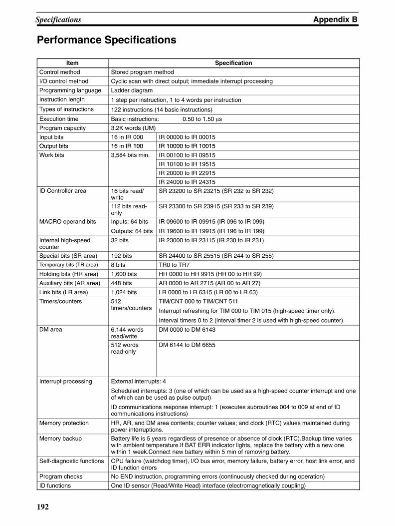
Appendix BSpecifications
192
Performance Specifications
Item Specification
Control method Stored program method
I/O control method Cyclic scan with direct output; immediate interrupt processing
Programming language Ladder diagram
Instruction length 1 step per instruction, 1 to 4 words per instruction
Types of instructions 122 instructions (14 basic instructions)
Execution time Basic instructions: 0.50 to 1.50 s
Program capacity 3.2K words (UM)
Input bits 16 in IR 000 IR 00000 to IR 00015
Output bits 16 in IR 100 IR 10000 to IR 10015Output bits 16 in IR 100 IR 10000 to IR 10015
Work bits 3,584 bits min. IR 00100 to IR 09515,
IR 10100 to IR 19515
IR 20000 to IR 22915
IR 24000 to IR 24315
ID Controller area 16 bits read/write
SR 23200 to SR 23215 (SR 232 to SR 232)
112 bits read-only
SR 23300 to SR 23915 (SR 233 to SR 239)
MACRO operand bits Inputs: 64 bits
Outputs: 64 bits
IR 09600 to IR 09915 (IR 096 to IR 099)
IR 19600 to IR 19915 (IR 196 to IR 199)
Internal high-speedcounter
32 bits IR 23000 to IR 23115 (IR 230 to IR 231)
Special bits (SR area) 192 bits SR 24400 to SR 25515 (SR 244 to SR 255)
Temporary bits (TR area) 8 bits TR0 to TR7
Holding bits (HR area) 1,600 bits HR 0000 to HR 9915 (HR 00 to HR 99)
Auxiliary bits (AR area) 448 bits AR 0000 to AR 2715 (AR 00 to AR 27)
Link bits (LR area) 1,024 bits LR 0000 to LR 6315 (LR 00 to LR 63)
Timers/counters 512timers/counters
TIM/CNT 000 to TIM/CNT 511
Interrupt refreshing for TIM 000 to TIM 015 (high-speed timer only).
Interval timers 0 to 2 (interval timer 2 is used with high-speed counter).
DM area 6,144 wordsread/write
DM 0000 to DM 6143
512 wordsread-only
DM 6144 to DM 6655
Interrupt processing External interrupts: 4
Scheduled interrupts: 3 (one of which can be used as a high-speed counter interrupt and oneof which can be used as pulse output)
ID communications response interrupt: 1 (executes subroutines 004 to 009 at end of IDcommunications instructions)
Memory protection HR, AR, and DM area contents; counter values; and clock (RTC) values maintained duringpower interruptions.
Memory backup Battery life is 5 years regardless of presence or absence of clock (RTC).Backup time varieswith ambient temperature.If BAT ERR indicator lights, replace the battery with a new onewithin 1 week.Connect new battery within 5 min of removing battery.
Self-diagnostic functions CPU failure (watchdog timer), I/O bus error, memory failure, battery error, host link error, andID function errors
Program checks No END instruction, programming errors (continuously checked during operation)
ID functions One ID sensor (Read/Write Head) interface (electromagnetically coupling)

193
Appendix CDimensions
The overall dimensions of the ID Controller are 219 110 107 mm (WHD).
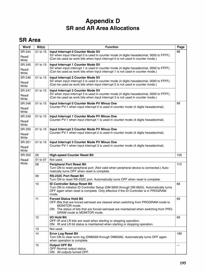
195
Appendix DSR and AR Area Allocations
SR AreaWord Bit(s) Function Page
SR 244
Read/Write
01 to 15 Input Interrupt 0 Counter Mode SVSV when input interrupt 0 is used in counter mode (4 digits hexadecimal, 0000 to FFFF).(Can be used as work bits when input interrupt 0 is not used in counter mode.)
98
SR 245
Read/Write
01 to 15 Input Interrupt 1 Counter Mode SVSV when input interrupt 1 is used in counter mode (4 digits hexadecimal, 0000 to FFFF).(Can be used as work bits when input interrupt 1 is not used in counter mode.)
SR 246
Read/Write
01 to 15 Input Interrupt 2 Counter Mode SVSV when input interrupt 2 is used in counter mode (4 digits hexadecimal, 0000 to FFFF).(Can be used as work bits when input interrupt 2 is not used in counter mode.)
SR 247
Read/Write
01 to 15 Input Interrupt 3 Counter Mode SVSV when input interrupt 3 is used in counter mode (4 digits hexadecimal, 0000 to FFFF).(Can be used as work bits when input interrupt 3 is not used in counter mode.)
SR 248
Read/Write
01 to 15 Input Interrupt 0 Counter Mode PV Minus OneCounter PV-1 when input interrupt 0 is used in counter mode (4 digits hexadecimal).
99
SR 249
Read/Write
01 to 15 Input Interrupt 1 Counter Mode PV Minus OneCounter PV-1 when input interrupt 1 is used in counter mode (4 digits hexadecimal).
SR 250
Read/Write
01 to 15 Input Interrupt 2 Counter Mode PV Minus OneCounter PV-1 when input interrupt 2 is used in counter mode (4 digits hexadecimal).
SR 251
Read/Write
01 to 15 Input Interrupt 3 Counter Mode PV Minus OneCounter PV-1 when input interrupt 3 is used in counter mode (4 digits hexadecimal).
SR 252 00 High-speed Counter Reset Bit 105
Read/ 01 to 07 Not used.Read/Write 08 Peripheral Port Reset Bit
Turn ON to reset peripheral port. (Not valid when peripheral device is connected.) Auto-matically turns OFF when reset is complete.
113
09 RS-232C Port Reset BitTurn ON to reset RS-232C port. Automatically turns OFF when reset is complete.
10 ID Controller Setup Reset BitTurn ON to initialize ID Controller Setup (DM 6600 through DM 6655). Automatically turnsOFF again when reset is complete. Only effective if the ID Controller is in PROGRAMmode.
68
11 Forced Status Hold BitOFF:Bits that are forced set/reset are cleared when switching from PROGRAM mode to
MONITOR mode.ON: The status of bits that are forced set/reset are maintained when switching from PRO-
GRAM mode to MONITOR mode.
69
12 I/O Hold BitOFF: IR and LR bits are reset when starting or stopping operation.ON: IR and LR bit status is maintained when starting or stopping operation.
69
13 Not used.
14 Error Log Reset BitTurn ON to clear error log (DM6569 through DM6599). Automatically turns OFF againwhen operation is complete.
180
15 Output OFF BitOFF:Normal output status.ON: All outputs turned OFF.
---

Appendix DSR and AR Area Allocations
196
Word PageFunctionBit(s)SR 253
Read-only
00 to 07 FAL Error CodeThe error code (a 2-digit number) is stored here when an error occurs. The FAL number isstored here when FAL(06) or FALS(07) is executed. This word is reset (to 00) by executinga FAL 00 instruction or by clearing the error from a Peripheral Device.
---
08 Low Battery FlagTurns ON when the ID Controller battery voltage drops.
176
09 Cycle Time Overrun FlagTurns ON when a cycle time overrun occurs (i.e., when the cycle time exceeds 100 ms).
176
10 to 12 Not used.
13 Always ON Flag ---
14 Always OFF Flag ---
15 First Cycle FlagTurns ON for 1 cycle at the start of operation.
---
SR 254 00 1-minute clock pulse (30 seconds ON; 30 seconds OFF) ---
Read- 01 0.02-second clock pulse (0.01 second ON; 0.01 second OFF) ---Readonly 02 to 03 Not used.
04 Overflow (OF) FlagTurns ON when the result of a calculation is above the upper limit of signed binary data.
---
05 Underflow (UF) FlagTurns ON when the result of a calculation is below the lower limit of signed binary data.
---
06 Differential Monitor Complete FlagTurns ON when differential monitoring is complete.
56
07 STEP(08) Execution FlagTurns ON for 1 cycle only at the start of process based on STEP(08).
---
08 HKY(––) Execution FlagTurns ON during execution of HKY(––).
---
09 7SEG(––) Execution FlagTurns ON during execution of 7SEG(––).
---
10 DSW(––) Execution FlagTurns ON during execution of DSW(––).
---
11 to 14 Not used.
15 ID Function Error Flag Turns ON when there is an error in an ID function.
---
SR 255 00 0.1-second clock pulse (0.05 second ON; 0.05 second OFF) ---
Read- 01 0.2-second clock pulse (0.1 second ON; 0.1 second OFF) ---Readonly 02 1.0-second clock pulse (0.5 second ON; 0.5 second OFF) ---
03 Instruction Execution Error (ER) FlagTurns ON when an error occurs during execution of an instruction.
---
04 Carry (CY) FlagTurns ON when there is a carry in the results of an instruction execution.
---
05 Greater Than (GR) FlagTurns ON when the result of a comparison operation is “greater.”
---
06 Equals (EQ) FlagTurns ON when the result of a comparison operation is “equal,” or when the result of aninstruction execution is 0.
---
07 Less Than (LE) FlagTurns ON when the result of a comparison operation is “less.”
---
08 to 15 Not used.
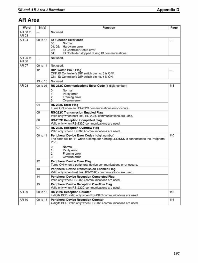
Appendix DSR and AR Area Allocations
197
AR AreaWord Bit(s) Function Page
AR 00 toAR 03
--- Not used.
AR 04 08 to 15 ID Function Error code00: Normal01, 02: Hardware error03: ID Controller Setup error04: ID Controller stopped during ID communications
---
AR 05 toAR 06
--- Not used.
AR 07 00 to 11 Not used.
12 DIP Switch Pin 6 FlagOFF: ID Controller’s DIP switch pin no. 6 is OFF.ON: ID Controller’s DIP switch pin no. 6 is ON.
---
13 to 15 Not used.
AR 08 00 to 03 RS-232C Communications Error Code (1-digit number)
0: Normal1: Parity error2: Framing error3: Overrun error
113
04 RS-232C Error FlagTurns ON when an RS-232C communications error occurs.
05 RS-232C Transmission Enabled FlagValid only when host link, RS-232C communications are used.
06 RS-232C Reception Completed FlagValid only when RS-232C communications are used.
07 RS-232C Reception Overflow FlagValid only when RS-232C communications are used.
08 to 11 Peripheral Device Error Code (1-digit number)The code will be “F” when a computer running LSS/SSS is connected to the PeripheralPort.
0: Normal1: Parity error2: Framing error3: Overrun error
116
12 Peripheral Device Error FlagTurns ON when a peripheral device communications error occurs.
13 Peripheral Device Transmission Enabled FlagValid only when host link, RS-232C communications are used.
14 Peripheral Device Reception Completed FlagValid only when RS-232C communications are used.
15 Peripheral Device Reception Overflow FlagValid only when RS-232C communications are used.
AR 09 00 to 15 RS-232C Reception Counter4 digits BCD; valid only when RS-232C communications are used.
116
AR 10 00 to 15 Peripheral Device Reception Counter4 digits BCD; valid only when RS-232C communications are used.
116
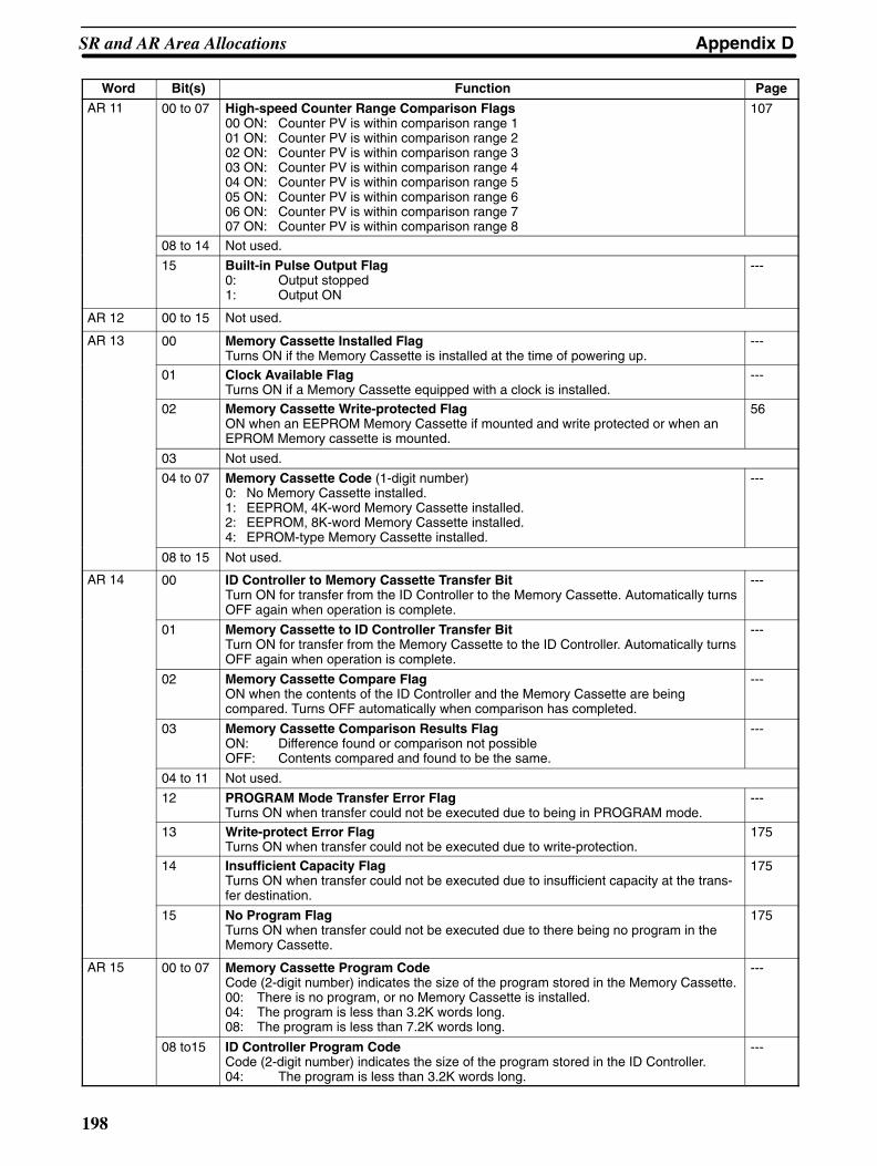
Appendix DSR and AR Area Allocations
198
Word PageFunctionBit(s)AR 11 00 to 07 High-speed Counter Range Comparison Flags
00 ON: Counter PV is within comparison range 101 ON: Counter PV is within comparison range 202 ON: Counter PV is within comparison range 303 ON: Counter PV is within comparison range 404 ON: Counter PV is within comparison range 505 ON: Counter PV is within comparison range 606 ON: Counter PV is within comparison range 707 ON: Counter PV is within comparison range 8
107
08 to 14 Not used.
15 Built-in Pulse Output Flag0: Output stopped1: Output ON
---
AR 12 00 to 15 Not used.
AR 13 00 Memory Cassette Installed FlagTurns ON if the Memory Cassette is installed at the time of powering up.
---
01 Clock Available FlagTurns ON if a Memory Cassette equipped with a clock is installed.
---
02 Memory Cassette Write-protected FlagON when an EEPROM Memory Cassette if mounted and write protected or when anEPROM Memory cassette is mounted.
56
03 Not used.
04 to 07 Memory Cassette Code (1-digit number)0: No Memory Cassette installed.1: EEPROM, 4K-word Memory Cassette installed.2: EEPROM, 8K-word Memory Cassette installed.4: EPROM-type Memory Cassette installed.
---
08 to 15 Not used.
AR 14 00 ID Controller to Memory Cassette Transfer BitTurn ON for transfer from the ID Controller to the Memory Cassette. Automatically turnsOFF again when operation is complete.
---
01 Memory Cassette to ID Controller Transfer BitTurn ON for transfer from the Memory Cassette to the ID Controller. Automatically turnsOFF again when operation is complete.
---
02 Memory Cassette Compare FlagON when the contents of the ID Controller and the Memory Cassette are beingcompared. Turns OFF automatically when comparison has completed.
---
03 Memory Cassette Comparison Results FlagON: Difference found or comparison not possibleOFF: Contents compared and found to be the same.
---
04 to 11 Not used.
12 PROGRAM Mode Transfer Error FlagTurns ON when transfer could not be executed due to being in PROGRAM mode.
---
13 Write-protect Error FlagTurns ON when transfer could not be executed due to write-protection.
175
14 Insufficient Capacity FlagTurns ON when transfer could not be executed due to insufficient capacity at the trans-fer destination.
175
15 No Program FlagTurns ON when transfer could not be executed due to there being no program in theMemory Cassette.
175
AR 15 00 to 07 Memory Cassette Program CodeCode (2-digit number) indicates the size of the program stored in the Memory Cassette.00: There is no program, or no Memory Cassette is installed.04: The program is less than 3.2K words long.08: The program is less than 7.2K words long.
---
08 to15 ID Controller Program CodeCode (2-digit number) indicates the size of the program stored in the ID Controller.04: The program is less than 3.2K words long.
---
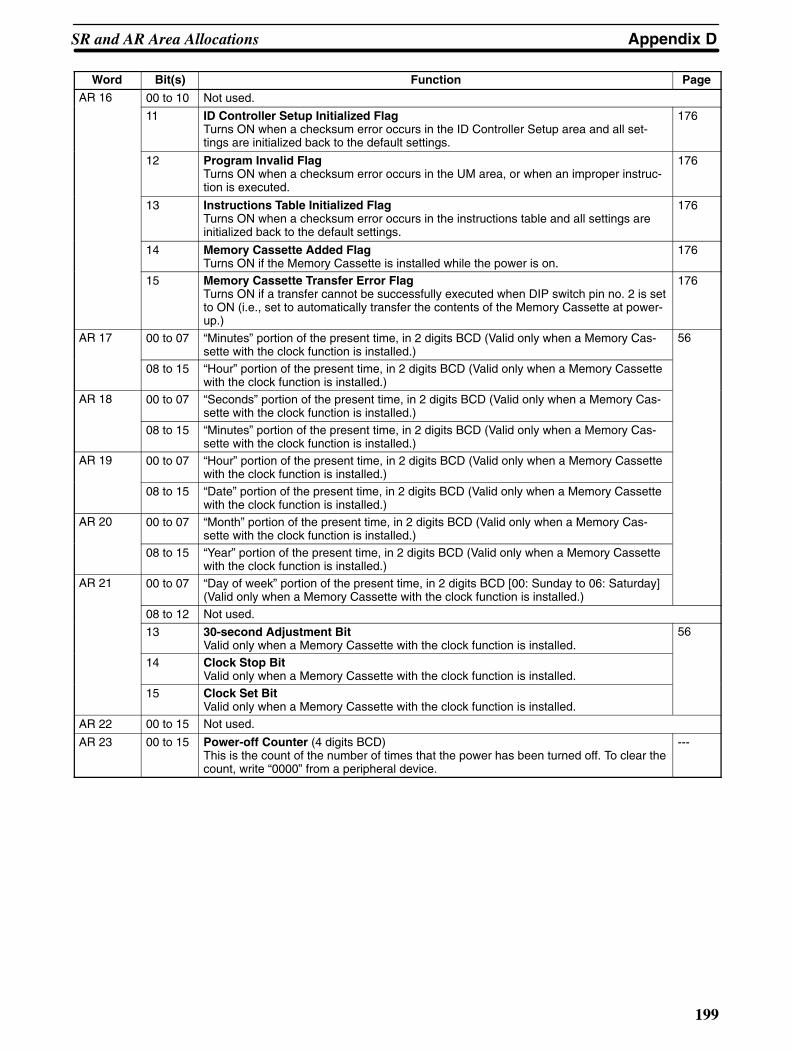
Appendix DSR and AR Area Allocations
199
Word PageFunctionBit(s)AR 16 00 to 10 Not used.
11 ID Controller Setup Initialized FlagTurns ON when a checksum error occurs in the ID Controller Setup area and all set-tings are initialized back to the default settings.
176
12 Program Invalid FlagTurns ON when a checksum error occurs in the UM area, or when an improper instruc-tion is executed.
176
13 Instructions Table Initialized FlagTurns ON when a checksum error occurs in the instructions table and all settings areinitialized back to the default settings.
176
14 Memory Cassette Added FlagTurns ON if the Memory Cassette is installed while the power is on.
176
15 Memory Cassette Transfer Error FlagTurns ON if a transfer cannot be successfully executed when DIP switch pin no. 2 is setto ON (i.e., set to automatically transfer the contents of the Memory Cassette at power-up.)
176
AR 17 00 to 07 “Minutes” portion of the present time, in 2 digits BCD (Valid only when a Memory Cas-sette with the clock function is installed.)
56
08 to 15 “Hour” portion of the present time, in 2 digits BCD (Valid only when a Memory Cassettewith the clock function is installed.)
AR 18 00 to 07 “Seconds” portion of the present time, in 2 digits BCD (Valid only when a Memory Cas-sette with the clock function is installed.)
08 to 15 “Minutes” portion of the present time, in 2 digits BCD (Valid only when a Memory Cas-sette with the clock function is installed.)
AR 19 00 to 07 “Hour” portion of the present time, in 2 digits BCD (Valid only when a Memory Cassettewith the clock function is installed.)
08 to 15 “Date” portion of the present time, in 2 digits BCD (Valid only when a Memory Cassettewith the clock function is installed.)
AR 20 00 to 07 “Month” portion of the present time, in 2 digits BCD (Valid only when a Memory Cas-sette with the clock function is installed.)
08 to 15 “Year” portion of the present time, in 2 digits BCD (Valid only when a Memory Cassettewith the clock function is installed.)
AR 21 00 to 07 “Day of week” portion of the present time, in 2 digits BCD [00: Sunday to 06: Saturday](Valid only when a Memory Cassette with the clock function is installed.)
08 to 12 Not used.
13 30-second Adjustment BitValid only when a Memory Cassette with the clock function is installed.
56
14 Clock Stop BitValid only when a Memory Cassette with the clock function is installed.
15 Clock Set BitValid only when a Memory Cassette with the clock function is installed.
AR 22 00 to 15 Not used.
AR 23 00 to 15 Power-off Counter (4 digits BCD)This is the count of the number of times that the power has been turned off. To clear thecount, write “0000” from a peripheral device.
---
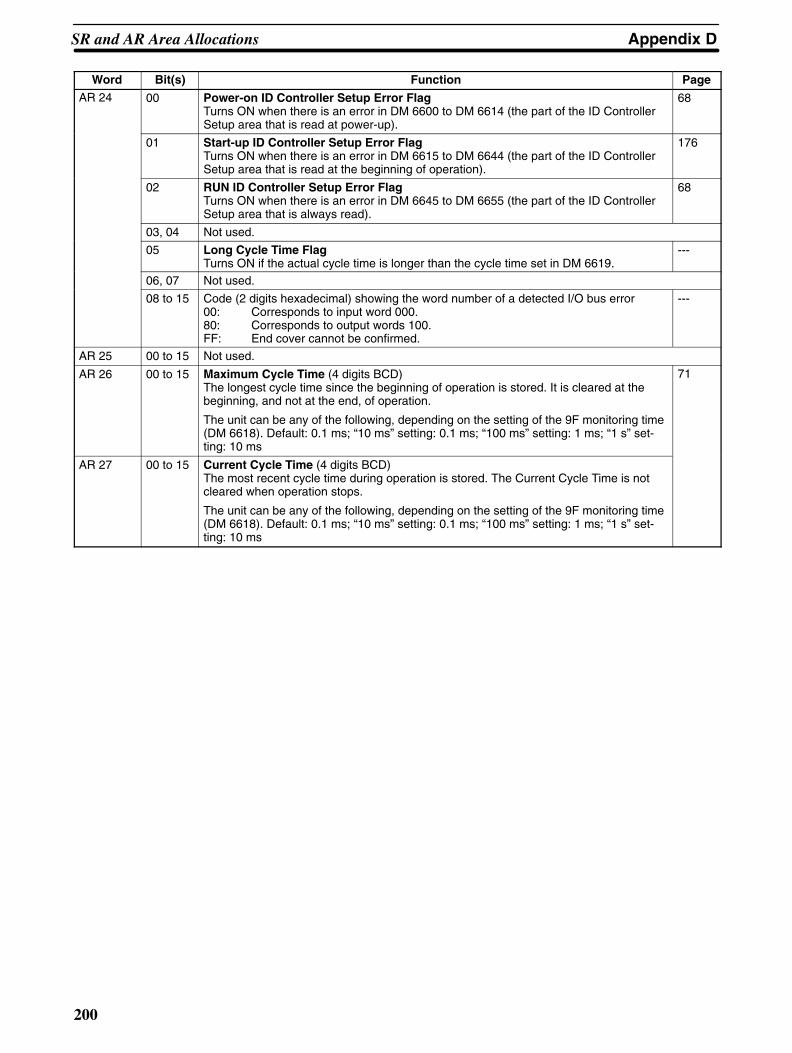
Appendix DSR and AR Area Allocations
200
Word PageFunctionBit(s)AR 24 00 Power-on ID Controller Setup Error Flag
Turns ON when there is an error in DM 6600 to DM 6614 (the part of the ID ControllerSetup area that is read at power-up).
68
01 Start-up ID Controller Setup Error FlagTurns ON when there is an error in DM 6615 to DM 6644 (the part of the ID ControllerSetup area that is read at the beginning of operation).
176
02 RUN ID Controller Setup Error FlagTurns ON when there is an error in DM 6645 to DM 6655 (the part of the ID ControllerSetup area that is always read).
68
03, 04 Not used.
05 Long Cycle Time FlagTurns ON if the actual cycle time is longer than the cycle time set in DM 6619.
---
06, 07 Not used.
08 to 15 Code (2 digits hexadecimal) showing the word number of a detected I/O bus error00: Corresponds to input word 000.80: Corresponds to output words 100.FF: End cover cannot be confirmed.
---
AR 25 00 to 15 Not used.
AR 26 00 to 15 Maximum Cycle Time (4 digits BCD) The longest cycle time since the beginning of operation is stored. It is cleared at thebeginning, and not at the end, of operation.
The unit can be any of the following, depending on the setting of the 9F monitoring time(DM 6618). Default: 0.1 ms; “10 ms” setting: 0.1 ms; “100 ms” setting: 1 ms; “1 s” set-ting: 10 ms
71
AR 27 00 to 15 Current Cycle Time (4 digits BCD) The most recent cycle time during operation is stored. The Current Cycle Time is notcleared when operation stops.
The unit can be any of the following, depending on the setting of the 9F monitoring time(DM 6618). Default: 0.1 ms; “10 ms” setting: 0.1 ms; “100 ms” setting: 1 ms; “1 s” set-ting: 10 ms
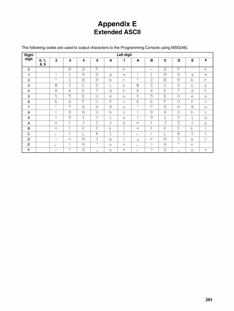
201
Appendix EExtended ASCII
The following codes are used to output characters to the Programming Console using MSG(46).
Rightdi it
Left digitgdigit 0, 1,
8, 92 3 4 5 6 7 A B C D E F
0 6 7 8 ) 6 7 8
1 9 : 1 ; 9 : 1 ;
2 5 < = 5 < =
3 . > . >
4 ? @ A ? @ A
5 B % ' 3 C B % ' 3 C
6 D * E F D * E F
7 G ( H I G ( H I
8 + ! J 0 K + ! J 0 K
9 , L M , L M
A N # O P Q N # O P Q
B R S " T U R S " T U
C V W $ X 4 Y V W $ X 4 Y
D ) Z [ \ Z [ \
E ] / 2 - ] / 2
F & ^ _ ` & ^ _ -
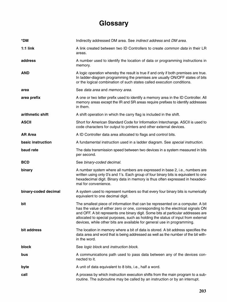
203
Glossary
*DM Indirectly addressed DM area. See indirect address and DM area.
1:1 link A link created between two ID Controllers to create common data in their LRareas.
address A number used to identify the location of data or programming instructions inmemory.
AND A logic operation whereby the result is true if and only if both premises are true.In ladder-diagram programming the premises are usually ON/OFF states of bitsor the logical combination of such states called execution conditions.
area See data area and memory area.
area prefix A one or two letter prefix used to identify a memory area in the ID Controller. Allmemory areas except the IR and SR areas require prefixes to identify addressesin them.
arithmetic shift A shift operation in which the carry flag is included in the shift.
ASCII Short for American Standard Code for Information Interchange. ASCII is used tocode characters for output to printers and other external devices.
AR Area A ID Controller data area allocated to flags and control bits.
basic instruction A fundamental instruction used in a ladder diagram. See special instruction.
baud rate The data transmission speed between two devices in a system measured in bitsper second.
BCD See binary-coded decimal.
binary A number system where all numbers are expressed in base 2, i.e., numbers arewritten using only 0’s and 1’s. Each group of four binary bits is equivalent to onehexadecimal digit. Binary data in memory is thus often expressed in hexadeci-mal for convenience.
binary-coded decimal A system used to represent numbers so that every four binary bits is numericallyequivalent to one decimal digit.
bit The smallest piece of information that can be represented on a computer. A bithas the value of either zero or one, corresponding to the electrical signals ONand OFF. A bit represents one binary digit. Some bits at particular addresses areallocated to special purposes, such as holding the status of input from externaldevices, while other bits are available for general use in programming.
bit address The location in memory where a bit of data is stored. A bit address specifies thedata area and word that is being addressed as well as the number of the bit with-in the word.
block See logic block and instruction block.
bus A communications path used to pass data between any of the devices con-nected to it.
byte A unit of data equivalent to 8 bits, i.e., half a word.
call A process by which instruction execution shifts from the main program to a sub-routine. The subroutine may be called by an instruction or by an interrupt.
Glossary
204
Carry Flag A flag that is used with arithmetic operations to hold a carry from an addition ormultiplication operation, or to indicate that the result is negative in a subtractionoperation. The carry flag is also used with certain types of shift operations.
central processing unit A device that is capable of storing programs and data, and executing the instruc-tions contained in the programs. In a ID Controller System, the central process-ing unit executes the program, processes I/O signals, communicates with exter-nal devices, etc.
CH See word.
channel See word.
checksum A sum transmitted with a data pack in communications. The checksum can berecalculated from the received data to confirm that the data in the transmissionhas not been corrupted.
clock pulse A pulse available at specific bits in memory for use in timing operations. Variousclock pulses are available with different pulse widths, and therefore different fre-quencies.
clock pulse bit A bit in memory that supplies a pulse that can be used to time operations. Vari-ous clock pulse bits are available with different pulse widths, and therefore differ-ent frequencies.
communications cable Cable used to transfer data between components of a control system and con-forming to the RS-232C or RS-422 standards.
Completion Flag A flag used with a timer or counter that turns ON when the timer has timed out orthe counter has reached its set value.
condition A symbol placed on an instruction line to indicate an instruction that controls theexecution condition for the terminal instruction. Each condition is assigned a bitin memory that determines its status. The status of the bit assigned to each con-dition determines the next execution condition. Conditions correspond to LOAD,LOAD NOT, AND, AND NOT, OR, or OR NOT instructions.
constant An input for an operand in which the actual numeric value is specified. Constantscan be input for certain operands in place of memory area addresses. Some op-erands must be input as constants.
control bit A bit in a memory area that is set either through the program or via a Program-ming Device to achieve a specific purpose.
control data An operand that specifies how an instruction is to be executed. The control datamay specify the part of a word is to be used as the operand, it may specify thedestination for a data transfer instructions, it may specify the size of a data tableused in an instruction, etc.
control signal A signal sent from the ID Controller to effect the operation of the controlled sys-tem.
Control System All of the hardware and software components used to control other devices. AControl System includes the ID Controller System, the ID Controller programs,and all I/O devices that are used to control or obtain feedback from the controlledsystem.
controlled system The devices that are being controlled by a ID Controller System.
count pulse The signal counted by a counter.
counter A dedicated group of digits or words in memory used to count the number oftimes a specific process has occurred, or a location in memory accessed

Glossary
205
through a TIM/CNT bit and used to count the number of times the status of a bitor an execution condition has changed from OFF to ON.
CPU See central processing unit.
CTS An acronym for clear-to-send, a signal used in communications between elec-tronic devices to indicate that the receiver is ready to accept incoming data.
CY See Carry Flag.
cycle One unit of processing performed by the CPU, including ladder program execu-tion, peripheral servicing, I/O refreshing, etc.
cycle time The time required to complete one cycle of CPU processing.
cyclic interrupt See scheduled interrupt.
data area An area in the ID Controller’s memory that is designed to hold a specific type ofdata.
data area boundary The highest address available within a data area. When designating an operandthat requires multiple words, it is necessary to ensure that the highest address inthe data area is not exceeded.
data length In communications, the number of bits that is to be treated as one unit in datatransmissions.
data link area A common data area established through a data link.
data sharing The process in which common data areas or common data words are createdbetween two or more ID Controllers.
data trace A process in which changes in the contents of specific memory locations are re-corded during program execution.
data transfer Moving data from one memory location to another, either within the same deviceor between different devices connected via a communications line or network.
debug A process by which a draft program is corrected until it operates as intended.Debugging includes both the removal of syntax errors, as well as the fine-tuningof timing and coordination of control operations.
decimal A number system where numbers are expressed to the base 10. In a ID Control-ler all data is ultimately stored in binary form, four binary bits are often used torepresent one decimal digit, via a system called binary-coded decimal.
decrement Decreasing a numeric value, usually by 1.
default A value automatically set by the ID Controller when the user does not specificallyset another value. Many devices will assume such default conditions upon theapplication of power.
destination The location where an instruction places the data on which it is operating, as op-posed to the location from which data is taken for use in the instruction. The loca-tion from which data is taken is called the source.
differentiated instruction An instruction that is executed only once each time its execution condition goesfrom OFF to ON. Non-differentiated instructions are executed for each scan aslong as the execution condition stays ON.
differentiation instruction An instruction used to ensure that the operand bit is never turned ON for morethan one scan after the execution condition goes either from OFF to ON for aDifferentiate Up instruction or from ON to OFF for a Differentiate Down instruc-tion.
Glossary
206
digit A unit of storage in memory that consists of four bits.
DIN track A rail designed to fit into grooves on various devices to allow the devices to bequickly and easily mounted to it.
DIP switch Dual in-line package switch, an array of pins in a signal package that is mountedto a circuit board and is used to set operating parameters.
direct output A method in which program execution results are output immediately to elimi-nate the affects of the cycle time.
DM area A data area used to hold only word data. Words in the DM area cannot be ac-cessed bit by bit.
DM word A word in the DM area.
EEPROM Electrically erasable programmable read-only memory; a type of ROM in whichstored data can be erased and reprogrammed. This is accomplished using aspecial control lead connected to the EEPROM chip and can be done withouthaving to remove the EEPROM chip from the device in which it is mounted.
electrical noise Random variations of one or more electrical characteristics such as voltage, cur-rent, and data, which might interfere with the normal operation of a device.
EPROM Erasable programmable read-only memory; a type of ROM in which stored datacan be erased, by ultraviolet light or other means, and reprogrammed.
error code A numeric code generated to indicate that an error exists, and something aboutthe nature of the error. Some error codes are generated by the system; othersare defined in the program by the operator.
Error Log Area An area used to store records indicating the time and nature of errors that haveoccurred in the system.
even parity A communication setting that adjusts the number of ON bits so that it is alwayseven. See parity.
event processing Processing that is performed in response to an event, e.g., an interrupt signal.
exclusive NOR A logic operation whereby the result is true if both of the premises are true or bothof the premises are false. In ladder-diagram programming, the premises areusually the ON/OFF states of bits, or the logical combination of such states,called execution conditions.
exclusive OR A logic operation whereby the result is true if one, and only one, of the premisesis true. In ladder-diagram programming the premises are usually the ON/OFFstates of bits, or the logical combination of such states, called execution condi-tions.
execution condition The ON or OFF status under which an instruction is executed. The executioncondition is determined by the logical combination of conditions on the same in-struction line and up to the instruction currently being executed.
execution cycle The cycle used to execute all processes required by the CPU, including programexecution, I/O refreshing, peripheral servicing, etc.
execution time The time required for the CPU to execute either an individual instruction or anentire program.
extended counter A counter created in a program by using two or more count instructions in suc-cession. Such a counter is capable of counting higher than any of the standardcounters provided by the individual instructions.

Glossary
207
extended timer A timer created in a program by using two or more timers in succession. Such atimer is capable of timing longer than any of the standard timers provided by theindividual instructions.
FAL error An error generated from the user program by execution of an FAL(06) instruc-tion.
FALS error An error generated from the user program by execution of an FALS(07) instruc-tion or an error generated by the system.
fatal error An error that stops ID Controller operation and requires correction before opera-tion can continue.
FCS See frame checksum.
flag A dedicated bit in memory that is set by the system to indicate some type of oper-ating status. Some flags, such as the carry flag, can also be set by the operatoror via the program.
force reset The process of forcibly turning OFF a bit via a programming device. Bits are usu-ally turned OFF as a result of program execution.
force set The process of forcibly turning ON a bit via a programming device. Bits are usu-ally turned ON as a result of program execution.
forced status The status of bits that have been force reset or force set.
frame checksum The results of exclusive ORing all data within a specified calculation range. Theframe checksum can be calculated on both the sending and receiving end of adata transfer to confirm that data was transmitted correctly.
function code A two-digit number used to input an instruction into the ID Controller.
hardware error An error originating in the hardware structure (electronic components) of the IDController, as opposed to a software error, which originates in software (i.e., pro-grams).
header code A code in an instruction that specifies what the instruction is to do.
hexadecimal A number system where all numbers are expressed to the base 16. In a ID Con-troller all data is ultimately stored in binary form, however, displays and inputs onProgramming Devices are often expressed in hexadecimal to simplify opera-tion. Each group of four binary bits is numerically equivalent to one hexadecimaldigit.
host computer A computer that is used to transfer data to or receive data from a ID Controller ina Host Link system. The host computer is used for data management and overallsystem control. Host computers are generally small personal or business com-puters.
host interface An interface that allows communications with a host computer.
host link An interface connecting a ID Controller to a host computer to enable monitoringor program control from the host computer.
HR area A memory area that preserves bit status during power interrupts and used aswork bits in programming.
I/O bit A bit in memory used to hold I/O status. Input bits reflect the status of input termi-nals; output bits hold the status for output terminals.
I/O capacity The number of inputs and outputs that a ID Controller is able to handle. Thisnumber ranges from around one hundred for smaller ID Controllers to two thou-sand for the largest ones.
Glossary
208
I/O delay The delay in time from when a signal is sent to an output to when the status of theoutput is actually in effect or the delay in time from when the status of an inputchanges until the signal indicating the change in the status is received.
I/O device A device connected to the I/O terminals. I/O devices may be either part of theControl System, if they function to help control other devices, or they may be partof the controlled system.
I/O interrupt An interrupt generated by a signal from I/O.
I/O point The place at which an input signal enters the ID Controller System, or at whichan output signal leaves the ID Controller System. In physical terms, I/O pointscorrespond to terminals or connector pins on the ID Controller; in terms of pro-gramming, an I/O points correspond to I/O bits in the IR area.
I/O refreshing The process of updating output status sent to external devices so that it agreeswith the status of output bits held in memory and of updating input bits in memoryso that they agree with the status of inputs from external devices.
I/O response time The time required for an output signal to be sent from the ID Controller in re-sponse to an input signal received from an external device.
I/O word A word in the IR area that is allocated in the ID Controller System and is used tohold I/O status.
IBM PC/AT or compatible A computer that has similar architecture to, that is logically compatible with, andthat can run software designed for an IBM PC/AT computer.
ID Controller Setup A group of operating parameters set in the ID Controller from a ProgrammingDevice to control ID Controller operation.
increment Increasing a numeric value, usually by 1.
indirect address An address whose contents indicates another address. The contents of the sec-ond address will be used as the actual operand.
initialization error An error that occurs either in hardware or software during the ID Controller Sys-tem startup, i.e., during initialization.
initialize Part of the startup process whereby some memory areas are cleared, systemsetup is checked, and default values are set.
input The signal coming from an external device into the ID Controller. The term inputis often used abstractly or collectively to refer to incoming signals.
input bit A bit in the IR area that is allocated to hold the status of an input.
input device An external device that sends signals into the ID Controller System.
input point The point at which an input enters the ID Controller System. Input points corre-spond physically to terminals or connector pins.
input signal A change in the status of a connection entering the ID Controller. Generally aninput signal is said to exist when, for example, a connection point goes from lowto high voltage or from a nonconductive to a conductive state.
instruction A direction given in the program that tells the ID Controller of the action to becarried out, and the data to be used in carrying out the action. Instructions can beused to simply turn a bit ON or OFF, or they can perform much more complexactions, such as converting and/or transferring large blocks of data.
instruction block A group of instructions that is logically related in a ladder-diagram program. Alogic block includes all of the instruction lines that interconnect with each other

Glossary
209
from one or more line connecting to the left bus bar to one or more right-handinstructions connecting to the right bus bar.
instruction execution time The time required to execute an instruction. The execution time for any one in-struction can vary with the execution conditions for the instruction and the oper-ands used in it.
instruction line A group of conditions that lie together on the same horizontal line of a ladder dia-gram. Instruction lines can branch apart or join together to form instructionblocks. Also called a rung.
interface An interface is the conceptual boundary between systems or devices and usual-ly involves changes in the way the communicated data is represented. Interfacedevices perform operations like changing the coding, format, or speed of thedata.
interrupt (signal) A signal that stops normal program execution and causes a subroutine to be runor other processing to take place.
interrupt program A program that is executed in response to an interrupt.
inverse condition See normally closed condition.
JIS An acronym for Japanese Industrial Standards.
jump A type of programming where execution moves directly from one point in a pro-gram to another, without sequentially executing any instructions in between.
jump number A definer used with a jump that defines the points from and to which a jump is tobe made.
ladder diagram (program) A form of program arising out of relay-based control systems that uses cir-cuit-type diagrams to represent the logic flow of programming instructions. Theappearance of the program is similar to a ladder, and thus the name.
ladder diagram symbol A symbol used in drawing a ladder-diagram program.
ladder instruction An instruction that represents the conditions on a ladder-diagram program. Theother instructions in a ladder diagram fall along the right side of the diagram andare called terminal instructions.
Ladder Support Software A software package installed on a IBM PC/AT or compatible computer to func-tion as a Programming Device.
least-significant (bit/word) See rightmost (bit/word).
LED Acronym for light-emitting diode; a device used as for indicators or displays.
leftmost (bit/word) The highest numbered bits of a group of bits, generally of an entire word, or thehighest numbered words of a group of words. These bits/words are often calledmost-significant bits/words.
link A hardware or software connection formed between two devices. “Link” can re-fer either to a part of the physical connection between two ID Controllers or asoftware connection created to data existing at another location (e.g., datalinks).
logic block A group of instructions that is logically related in a ladder-diagram program andthat requires logic block instructions to relate it to other instructions or logicblocks.
logic block instruction An instruction used to locally combine the execution condition resulting from alogic block with a current execution condition. The current execution condition
Glossary
210
could be the result of a single condition, or of another logic block. AND Load andOR Load are the two logic block instructions.
logic instruction Instructions used to logically combine the content of two words and output thelogical results to a specified result word. The logic instructions combine all thesame-numbered bits in the two words and output the result to the bit of the samenumber in the specified result word.
LR area A data area that is used in data links.
LSS See Ladder Support Software.
main program All of a program except for subroutine and interrupt programs.
mark trace A process in which changes in the contents of specific memory locations are re-corded during program execution.
masked bit A bit whose status has been temporarily made ineffective.
masking ‘Covering’ an interrupt signal so that the interrupt is not effective until the mask isremoved.
megabyte A unit of storage equal to one million bytes.
memory area Any of the areas in the ID Controller used to hold data or programs.
message number A number assigned to a message generated with the MESSAGE instruction.
mnemonic code A form of a ladder-diagram program that consists of a sequential list of the in-structions without using a ladder diagram.
MONITOR mode A mode of ID Controller operation in which normal program execution is possi-ble, and which allows modification of data held in memory. Used for monitoringor debugging the ID Controller.
most-significant (bit/word) See leftmost (bit/word).
NC input An input that is normally closed, i.e., the input signal is considered to be presentwhen the circuit connected to the input opens.
negative delay A delay set for a data trace in which recording data begins before the trace signalby a specified amount.
nesting Programming one loop within another loop, programming a call to a subroutinewithin another subroutine, or programming one jump within another.
NO input An input that is normally open, i.e., the input signal is considered to be presentwhen the circuit connected to the input closes.
noise interference Disturbances in signals caused by electrical noise.
nonfatal error A hardware or software error that produces a warning but does not stop the IDController from operating.
normal condition See normally open condition.
normally closed condition A condition that produces an ON execution condition when the bit assigned to itis OFF, and an OFF execution condition when the bit assigned to it is ON.
normally open condition A condition that produces an ON execution condition when the bit assigned to itis ON, and an OFF execution condition when the bit assigned to it is OFF.
NOT A logic operation which inverts the status of the operand. For example, ANDNOT indicates an AND operation with the opposite of the actual status of the op-erand bit.

Glossary
211
OFF The status of an input or output when a signal is said not to be present. The OFFstate is generally represented by a low voltage or by non-conductivity, but can bedefined as the opposite of either.
OFF delay The delay between the time when a signal is switched OFF (e.g., by an inputdevice or ID Controller) and the time when the signal reaches a state readable asan OFF signal (i.e., as no signal) by a receiving party (e.g., output device or IDController).
offset A positive or negative value added to a base value such as an address to specifya desired value.
ON The status of an input or output when a signal is said to be present. The ON stateis generally represented by a high voltage or by conductivity, but can be definedas the opposite of either.
ON delay The delay between the time when an ON signal is initiated (e.g., by an input de-vice or ID Controller) and the time when the signal reaches a state readable asan ON signal by a receiving party (e.g., output device or ID Controller).
one-to-one link See 1:1 link.
online edit The process of changed the program directly in the ID Controller from a Pro-gramming Device. Online editing is possible in PROGRAM or MONITOR mode.In MONITOR mode, the program can actually be changed while it is being
operand The values designated as the data to be used for an instruction. An operand canbe input as a constant expressing the actual numeric value to be used or as anaddress to express the location in memory of the data to be used.
operand bit A bit designated as an operand for an instruction.
operand word A word designated as an operand for an instruction.
operating modes One of three ID Controller modes: PROGRAM mode, MONITOR mode, andRUN mode.
operating error An error that occurs during actual ID Controller operation as opposed to an ini-tialization error, which occurs before actual operations can begin.
OR A logic operation whereby the result is true if either of two premises is true, or ifboth are true. In ladder-diagram programming the premises are usually ON/OFFstates of bits or the logical combination of such states called execution condi-tions.
output The signal sent from the ID Controller to an external device. The term output isoften used abstractly or collectively to refer to outgoing signals.
output bit A bit in the IR area that is allocated to hold the status to be sent to an output de-vice.
output device An external device that receives signals from the ID Controller System.
output point The point at which an output leaves the ID Controller System. Output points cor-respond physically to terminals or connector pins.
output signal A signal being sent to an external device. Generally an output signal is said toexist when, for example, a connection point goes from low to high voltage or froma nonconductive to a conductive state.
overflow The state where the capacity of a data storage location has been exceeded.
overseeing Part of the processing performed by the CPU that includes general tasks re-quired to operate the ID Controller.

Glossary
212
overwrite Changing the content of a memory location so that the previous content is lost.
parity Adjustment of the number of ON bits in a word or other unit of data so that thetotal is always an even number or always an odd number. Parity is generallyused to check the accuracy of data after being transmitted by confirming that thenumber of ON bits is still even or still odd.
parity check Checking parity to ensure that transmitted data has not been corrupted.
PC See Programmable Controller.
Peripheral Device Devices connected to a ID Controller System to aid in system operation. Periph-eral devices include printers, programming devices, external storage media,etc.
peripheral servicing Processing signals to and from peripheral devices, including refreshing, com-munications processing, interrupts, etc.
port A connector on a ID Controller or computer that serves as a connection to anexternal device.
positive delay A delay set for a data trace in which recording data begins after the trace signalby a specified amount.
present value The current value registered in a device at any instant during its operation. Pres-ent value is abbreviated as PV. The use of this term is generally restricted to tim-ers and counters.
printed circuit board A board onto which electrical circuits are printed for mounting into a computer orelectrical device.
PROGRAM mode A mode of operation that allows inputting and debugging of programs to be car-ried out, but that does not permit normal execution of the program.
Programmable Controller A computerized device that can accept inputs from external devices and gener-ate outputs to external devices according to a program held in memory. Pro-grammable Controllers are used to automate control of external devices. Al-though single-unit Programmable Controllers are available, building-block Pro-grammable Controllers are constructed from separate components. Such Pro-grammable Controllers are formed only when enough of these separate compo-nents are assembled to form a functional assembly.
programmed alarm An alarm given as a result of execution of an instruction designed to generate thealarm in the program, as opposed to one generated by the system.
programmed error An error arising as a result of the execution of an instruction designed to gener-ate the error in the program, as opposed to one generated by the system.
programmed message A message generated as a result of execution of an instruction designed to gen-erate the message in the program, as opposed to one generated by the system.
Programming Console The portable form of Programming Device for a ID Controller.
Programming Device A Peripheral Device used to input a program into a ID Controller or to alter ormonitor a program already held in the ID Controller. There are dedicated pro-gramming devices, such as Programming Consoles, and there are non-dedi-cated devices, such as a host computer.
PROM Programmable read-only memory; a type of ROM into which the program ordata may be written after manufacture, by a customer, but which is fixed fromthat time on.
protocol The parameters and procedures that are standardized to enable two devices tocommunicate or to enable a programmer or operator to communicate with a de-vice.
Glossary
213
PV See present value.
RAM Random access memory; a data storage media. RAM will not retain data whenpower is disconnected.
RAS An acronym for reliability, assurance, safety.
read-only area A memory area from which the user can read status but to which data cannot bewritten.
refresh The process of updating output status sent to external devices so that it agreeswith the status of output bits held in memory and of updating input bits in memoryso that they agree with the status of inputs from external devices.
relay-based control The forerunner of ID Controllers. In relay-based control, groups of relays are in-terconnected to form control circuits. In a ID Controller, these are replaced byprogrammable circuits.
reserved bit A bit that is not available for user application.
reserved word A word in memory that is reserved for a special purpose and cannot be accessedby the user.
reset The process of turning a bit or signal OFF or of changing the present value of atimer or counter to its set value or to zero.
response code A code sent with the response to a data transmission that specifies how thetransmitted data was processed.
response format A format specifying the data required in a response to a data transmission.
response monitoring time The time a device will wait for a response to a data transmission before assum-ing that an error has occurred.
Restart Bit A bit used to restart part of a device or process.
retrieve The processes of copying data either from an external device or from a storagearea to an active portion of the system such as a display buffer. Also, an outputdevice connected to the ID Controller is called a load.
retry The process whereby a device will re-transmit data which has resulted in an er-ror message from the receiving device.
return The process by which instruction execution shifts from a subroutine back to themain program (usually the point from which the subroutine was called).
reversible counter A counter that can be both incremented and decremented depending on thespecified conditions.
reversible shift register A shift register that can shift data in either direction depending on the specifiedconditions.
right-hand instruction See terminal instruction.
rightmost (bit/word) The lowest numbered bits of a group of bits, generally of an entire word, or thelowest numbered words of a group of words. These bits/words are often calledleast-significant bits/words.
rising edge The point where a signal actually changes from an OFF to an ON status.
ROM Read only memory; a type of digital storage that cannot be written to. A ROMchip is manufactured with its program or data already stored in it and can neverbe changed. However, the program or data can be read as many times as de-sired.

Glossary
214
rotate register A shift register in which the data moved out from one end is placed back into theshift register at the other end.
RS-232C interface An industry standard for serial communications.
RUN mode The operating mode used by the ID Controller for normal control operations.
rung See instruction line.
scan The process used to execute a ladder-diagram program. The program is ex-amined sequentially from start to finish and each instruction is executed in turnbased on execution conditions.
scan time See cycle time.
scheduled interrupt An interrupt that is automatically generated by the system at a specific time orprogram location specified by the operator. Scheduled interrupts result in the ex-ecution of specific subroutines that can be used for instructions that must be ex-ecuted repeatedly at a specified interval of time.
self diagnosis A process whereby the system checks its own operation and generates a warn-ing or error if an abnormality is discovered.
self-maintaining bit A bit that is programmed to maintain either an OFF or ON status until set or resetby specified conditions.
series A wiring method in which devices are wired consecutively in a string.
servicing The process whereby the ID Controller checks an interface or other connectionto see if special processing is required.
set The process of turning a bit or signal ON.
set value The value from which a decrementing counter starts counting down or to whichan incrementing counter counts up (i.e., the maximum count), or the time fromwhich or for which a timer starts timing. Set value is abbreviated SV.
shift input signal An input signal whose OFF to ON transition causes data to be shifted one bit.
shift register One or more words in which data is shifted a specified number of units to the rightor left in bit, digit, or word units. In a rotate register, data shifted out one end isshifted back into the other end. In other shift registers, new data (either specifieddata, zero(s) or one(s)) is shifted into one end and the data shifted out at the oth-er end is lost.
signed binary A binary value that is stored in memory along with a bit that indicates whether thevalue is positive or negative.
software error An error that originates in a software program.
source (word) The location from which data is taken for use in an instruction, as opposed to thelocation to which the result of an instruction is to be written. The latter is calledthe destination.
special instruction An instruction input with a function code that handles data processing opera-tions within ladder diagrams, as opposed to a basic instruction, which makes upthe fundamental portion of a ladder diagram.
SR area A memory area containing flags and other bits/words with specific functions.
SSS See SYSMAC Support Software.
subroutine A group of instructions placed separate from the main program and executedonly when called from the main program or activated by an interrupt.
Glossary
215
subroutine number A definer used to identify the subroutine that a subroutine call or interrupt acti-vates.
SV See set value.
switching capacity The maximum voltage/current that a relay can safely switch on and off.
syntax The form of a program statement (as opposed to its meaning).
syntax error An error in the way in which a program is written. Syntax errors can include‘spelling’ mistakes (i.e., a function code that does not exist), mistakes in specify-ing operands within acceptable parameters (e.g., specifying read-only bits as adestination), and mistakes in actual application of instructions (e.g., a call to asubroutine that does not exist).
SYSMAC Support Software A software package installed on a IBM PC/AT or compatible computer to func-tion as a Programming Device.
system configuration The arrangement in which devices in a System are connected. This term refersto the conceptual arrangement and wiring together of all the devices needed tocomprise the System.
system error An error generated by the system, as opposed to one resulting from execution ofan instruction designed to generate an error.
system error message An error message generated by the system, as opposed to one resulting fromexecution of an instruction designed to generate a message.
system setup Operating environment settings for a Programming Device, e.g., the LSS.
timer A location in memory accessed through a TIM/CNT bit and used to time downfrom the timer’s set value. Timers are turned ON and reset according to their ex-ecution conditions.
TR area A data area used to store execution conditions so that they can be reloaded laterfor use with other instructions.
TR bit A bit in the TR area.
trace An operation whereby the program is executed and the resulting data is stored toenable step-by-step analysis and debugging.
trace memory A memory area used to store the results of trace operations.
transfer The process of moving data from one location to another within the ID Controller,or between the ID Controller and external devices. When data is transferred,generally a copy of the data is sent to the destination, i.e., the content of thesource of the transfer is not changed.
transmission distance The distance that a signal can be transmitted.
trigger A signal used to activate some process, e.g., the execution of a trace operation.
trigger address An address in the program that defines the beginning point for tracing. The ac-tual beginning point can be altered from the trigger by defining either a positive ornegative delay.
UM area The memory area used to hold the active program, i.e., the program that is beingcurrently executed.
unmasked bit A bit whose status is effective. See masked bit.
unsigned binary A binary value that is stored in memory without any indication of whether it ispositive or negative.
Glossary
216
uploading The process of transferring a program or data from a lower-level or slave com-puter to a higher-level or host computer. If a Programming Devices is involved,the Programming Device is considered the host computer.
watchdog timer A timer within the system that ensures that the scan time stays within specifiedlimits. When limits are reached, either warnings are given or ID Controller opera-tion is stopped depending on the particular limit that is reached.
WDT See watchdog timer.
word A unit of data storage in memory that consists of 16 bits. All data areas consistsof words. Some data areas can be accessed only by words; others, by eitherwords or bits.
word address The location in memory where a word of data is stored. A word address mustspecify (sometimes by default) the data area and the number of the word that isbeing addressed.
work area A part of memory containing work words/bits.
work bit A bit in a work word.
work word A word that can be used for data calculation or other manipulation in program-ming, i.e., a ‘work space’ in memory. A large portion of the IR area is always re-served for work words. Parts of other areas not required for special purposesmay also be used as work words.
write protect switch A switch used to write-protect the contents of a storage device, e.g., a floppydisk. If the hole on the upper left of a floppy disk is open, the information on thisfloppy disk cannot be altered.
write-protect A state in which the contents of a storage device can be read but cannot be al-tered.
217
Index
7-segment displays, output instruction, 91
advanced I/O instructions7-SEGMENT DISPLAY OUTPUT, 91DIGITAL SWITCH INPUT, 89functions, 86HEXADECIMAL KEY INPUT, 88TEN-KEY INPUT, 86using alternate I/O bits, 93
ambient temperature, 16
applications, examples, 4, 156
AR Area, allocations, 197
ASCII, converting displays, 49
autobooting, 10
autoreadcancelling, 74, 82flags, 61standby time, 74
autowritecancelling, 74, 82flags, 61standby time, 74
basic instructions, 140
Battery Set, 10model number, 25replacement, 25
BCDconverting, 127definition, 127
binary, definition, 127
binary data, modifying, 51
bit status, force-set/reset, 49
buzzer operation, Programming Console, 41
cables, model numbers, 189
check levels, program checks, 173
checking, program syntax, 47
clearing, memory areas, 39
clock, 13reading and changing, 42
communication errors, 176
communications, 110See also ID communicationserrors, 4host link, 112, 113link, 118one-to-one, 118overview, 3receiving data, 150sending data, 151settings, 111standard. See settingstroubleshooting, 182types, 110
comparing data, 145
components, 10
connections, Read/Write Heads, 31
connectorsapplicable models, 28crimp connectors, 31
contact outputs, specifications, 24
countersconditions when reset, 143creating, 143creating extended timers, 144
current consumption, 23, 24
cycle time, displaying, 49
dataconverting, 128modifying, 51
data areas. See memory areas
Data Carrierscapacity, 76checking, 83clearing, 82, 137communications time, 165list, 25memory, 75production date, 76reading, 79, 134
example, 157, 159service life management, 77, 83, 138speed, 168standby time, 74write protection, 76, 77writing, 80, 136
example, 156, 158
date, reading and changing, 42
definers, definition, 126
Index
218
differentiated instructions, 133entering, 46function codes, 126
digit numbers, 127
dimensions, 193
DIN Track, 28
DIP switch, 10
displaysconverting between hex and ASCII, 49cycle time, 49
DM Area, protecting, 10
ductsI/O wiring, 17power cables, 17
EEPROM, write protection, 14
electrostatic charges, 16
EMC, 31
EPROM chips, 14installation, 14
error logs, 179control bits, 60FAL numbers, 174ID, overview, 4reading, 38settings, 68, 71, 72
errorsSee also error logscommunications, 4, 176fatal, 176, 177general, 172ID communications error flags, 60, 178indicators, 11non-fatal, 175, 177programming, 173Programming Console operations, 173reading error logs, 38reading/clearing messages, 40troubleshooting via ID indicators, 177types, 172user message displays, 174user-programmed errors, 174
expansion instructions, 52, 125reading and changing, 41setting for defaults, 10
FAL(06), 174
FALS(07), 174
features, 3
flagsAR Area, 197arithmetic, 146resetting, 60SR Area, 195
force resetting, 49
force setting, 49
force-set/reset, 49clearing, 50
function codes, 126reading and changing, 41
ground, precautions, 30
hexadecimal, definition, 127
hexadecimal data, converting displays, 49
high-speed counterinterrupts, 104memory area, 56settings, 66
high-speed counter interrupts, delays, 21
host linkcommunications, 113node number, 113setting parameters, 115
See also RS-232C
humidity, 16
I/Omemory areas, 57specifications, 15, 21wiring, 18
I/O refresh operations, types, 163
ID communication errors. See communications, errors
ID communications, 73application examples, 155error flags, 60, 178execution time, 165, 168flags, 61indicators, 11instructions, 3, 78, 134interrupts, 85, 96memory area, 56, 60response refresh method, 73settings, 73specifications, 15testing, 35, 37troubleshooting errors, 177
ID Controller area, 56, 60
ID Controller Setup. See settings
ID Controllers, models, 189
ID error log. See error logs
Index
219
indicators, 10, 11
inductive loads, 19
inputdigital switches, 89hexadecimal keys, 88
input devices, wiring, 20
input terminals, 10
inputs, indicators, 11
inrush current, 19
installationambient conditions, 16clearance, 16cooling fan, 16mounting, 28mounting direction, 18precautions, 16
instruction set, 122AND, 140AND LD, 131, 132, 141AND NOT, 140CMP(20), 145CNT, 143END(01), 145ID communications, 134IDAR(63), 78, 79, 134IDAW(64), 78, 80, 136IDCA(65), 82, 137IDMD(66), 83, 138IDRD(61), 79, 134IDWT(62), 80, 136LD, 140LD NOT, 140MOV(21), 146MOVD(83), 147OR, 140OR LD, 131, 133, 141OR NOT, 140OUT, 141OUT NOT, 141RSET, 142RXD(––), 150SET, 142TIM, 142TXD(––), 151XFER(70), 149
instructionsadvanced I/O, 86basic, 140execution times, 165inserting and deleting, 44
interrupts, 94counter mode, 98high-speed counter, 107high-speed counter 0, 104ID communications instructions, 85, 96input, 96inputs, 96interval timers, 101, 103masking, 101ON/OFF delays, 21
overview, 3setting modes, 97settings, 65types, 94unmasking, 101
key input, hexadecimal, 88
ladder diagraminstructions, 126notation, 126using logic blocks, 131
Ladder Support Software. See LSS
leakage current, 18
LEDs. See CPU, indicators
leftmost, definition, 127
logic block instructions, converting to mnemonic code,131–133
logic blocksSee also ladder diagraminstructions, 141
LSS, 34connection, 25models, 25operations, 52
macros, memory area, 56
memoryprotection, 10write protecting DC memory, 76
memory areasAR Area, 58clearing, 39DM Area, 59HR Area, 57IR Area, 57link bits, 58partial clear, 40SR Area, 57structure, 56timer and counter bits, 58TR Area, 57user program memory, 59work bits, 57
Memory Cassettes, 10, 13, 59autobooting, 10installation, 13models, 25, 189
mode selector, Programming Console, 12
model numbers, 189
modifyingbinary data, 51hexadecimal/BCD data, 51
Index
220
MONITOR mode, description, 12
monitoringbinary monitor, 50–51status, 47
mounting, preventing noise, 17
moving data, 146blocks, 149digits, 147
MSG(46), 174
noise, prevention, 17, 19
one-to-one link, wiring, 27
operands, 126
operating modes, 12
operation. See Programming Console
operationsaffects of scan time, 164internal processing, 162
output, 7-segment displays, 91
output terminals, 10
outputscontrolling, 141, 142indicators, 11inhibiting, indicator, 11turning OFF, 176
peripheral deviceslist, 25models, 189
peripheral port, 10indicator, 11settings, 64, 67
ports, settings, 64, 66, 67
power supply, 10specifications, 15wiring, 30
precautions, 30
precautionsground, 30installation, 16programming, 128wiring, 18
proceduresSee also Programming Consoleoverall, 7
program, automatic transfer, 13
Program Memory, setting address and reading content, 43
PROGRAM mode, description, 12
Programmable Terminals, 3application example, 5, 156
programmingchecks for syntax, 47errors, 173examples, 156high-speed counter, 107inserting and deleting instructions, 44–45interrupts, 107precautions, 128setting and reading a memory address, 43
Programming Console, 34connecting, 35connection, 25displayed language, 10displays, 36error displays, 4keys, 34mode selector, 12models, 25, 34monitoring errors, 35operations, 37preparations for operation, 34reading error logs, 38testing ID communications, 35
programming devices, 25, 34
programschecking, 173entering and editing, 45
protectionEEPROM, 14memory, 10
Read/Write Headsconnecting, 31connector, 10list, 25
rightmost, definition, 127
RS-232C portcommunications, 114, 115, 116, 118connecting Units, 118control bits, 116selecting. See host linksettings, 64, 66
RS-232C port, 10communications, 10connectable devices, 26indicator, 11one-to-one link, 27specifications, 27, 28wiring example, 27
RUN mode, description, 12
Index
221
scan timeaffects on operations, 164calculating, 163processes, 163
settingsbasic operations, 69, 70, 71changing, 68communications, 110, 111, 112defaults, 64, 68DSW(––), 71I/O operations, 69, 70interrupts, 94, 96, 97SPED(––), 71
setup. See settings
specifications, 191basic, 15contact outputs, 24I/O, 21inputs, 21transistor outputs, 23
SR Area, allocations, 195
SSSconnection, 25models, 25
startup, settings, 64
static electricity, preventing, 16
status, monitoring, 47
subroutines, ID communications instructions, 73
switch input, digital, 89
switches, DIP. See DIP switch
syntax, checking the program, 47
SYSMAC Support Software. See SSS
system configuration, 15example, 2
ten-key, inputting, 86
terminal blocksremoval, 18wiring, 30
time, reading and changing, 42
timersconditions when reset, 143creating, 142–143
timinginstruction execution. See instructionscan time, 163
transfers, program, 52, 53
troubleshooting, 181
UMSee also Program Memoryprotecting, 10
weight, 191
wiringAC power supply, 30precautions, 18
words, definition, 127
write protection, 76setting, 76, 77
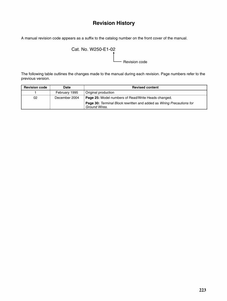
223
Revision History
A manual revision code appears as a suffix to the catalog number on the front cover of the manual.
Cat. No. W250-E1-02
Revision code
The following table outlines the changes made to the manual during each revision. Page numbers refer to theprevious version.
Revision code Date Revised content
1 February 1995 Original production
02 December 2004 Page 25: Model numbers of Read/Write Heads changed.
Page 30: Terminal Block rewritten and added as Wiring Precautions forGround Wires.
Related Documents