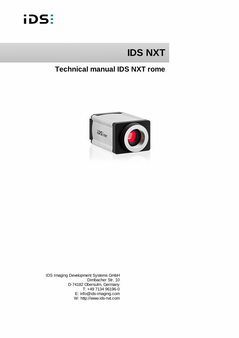
IDS NXT IDS Imaging Development Systems GmbH Dimbacher Str. 10 D-74182 Obersulm, Germany T: +49 7134 96196-0 E: [email protected] W: http://www.ids-nxt.com Technical manual IDS NXT rome

Welcome message from author
This document is posted to help you gain knowledge. Please leave a comment to let me know what you think about it! Share it to your friends and learn new things together.
Transcript
IDS NXT
IDS Imaging Development Systems GmbHDimbacher Str. 10
D-74182 Obersulm, GermanyT: +49 7134 96196-0
E: [email protected]: http://www.ids-nxt.com
Technical manual IDS NXT rome
2021-11-08 2
IDS NXT: Technical manual IDS NXT rome
Contents
1 Preface .............................................................................................................................................. 3
2 Symbols and hints ............................................................................................................................ 5
3 Safety instructions ............................................................................................................................ 6
4 Standards and directives .................................................................................................................. 9
5 IDS NXT rome .................................................................................................................................. 11
5.1 Ambient conditions ..................................................................................................................... 11
5.2 Connecting a IDS NXT rome ....................................................................................................... 13
6 Mechanical specifications ................................................................................................................ 15
7 Electrial specifications ..................................................................................................................... 16
7.1 Pin assignment GigE connector (M12) ......................................................................................... 16
7.2 Pin assignment I/O connector ..................................................................................................... 17
7.3 Digital input wiring ...................................................................................................................... 18
7.4 Digital output wiring .................................................................................................................... 19
7.5 RS-232 wiring ............................................................................................................................ 21
8 Status LED ...................................................................................................................................... 23
9 Optical specifications ...................................................................................................................... 24
9.1 Immersion depth for lenses ......................................................................................................... 24
9.2 Position accuracy of the sensor .................................................................................................. 24
10 Filter glasses ................................................................................................................................. 26
10.1 Filter types .............................................................................................................................. 26
10.2 Cleaning the filter glasses ......................................................................................................... 28
11 System specification ...................................................................................................................... 30
11.1 CNN ........................................................................................................................................ 30
11.1.1 deep ocean core .......................................................................................................... 30
11.1.2 Benchmark ................................................................................................................... 31
Index .................................................................................................................................................. 32

2021-11-08 3
IDS NXT: Technical manual IDS NXT rome
1 Preface
Introduction
IDS Imaging Development Systems GmbH has taken every possible care in preparing this manual. We
however assume no liability for the content, completeness or quality of the information contained therein. The
content of this manual is regularly updated and adapted to reflect the current status of the software. We
furthermore do not guarantee that this product will function without errors, even if the stated specifications are
adhered to.
Under no circumstances can we guarantee that a particular objective can be achieved with the purchase of
this product.
Insofar as permitted under statutory regulations, we assume no liability for direct damage, indirect damage or
damages suffered by third parties resulting from the purchase of this product. In no event shall any liability
exceed the purchase price of the product.
Please note that the content of this manual is neither part of any previous or existing agreement, promise,
representation or legal relationship, nor an alteration or amendment thereof. All obligations of IDS Imaging
Development Systems GmbH result from the respective contract of sale, which also includes the complete and
exclusively applicable warranty regulations. These contractual warranty regulations are neither extended nor
limited by the information contained in this manual. Should you require further information on this product, or
encounter specific problems that are not discussed in sufficient detail in the manual, please contact your local
dealer or system installer.
Trademarks
The IDS logo is a registered trademark of IDS Imaging Development Systems GmbH,
registered for U.S. (Reg.No. 4,513,138) and other countries.
IDS NXT and uEye are registered trademarks of IDS Imaging Development Systems GmbH. Microsoft and
Windows are trademarks or registered trademarks of Microsoft Corporation. All other products or company
names mentioned in this manual are used solely for purposes of identification or description and may be
trademarks or registered trademarks of the respective owners.
Copyright
© IDS Imaging Development Systems GmbH. All rights reserved. This manual may not be reproduced,
transmitted or translated to another language, either as a whole or in parts, without the prior written permission
of IDS Imaging Development Systems GmbH.
Status: November 2021
Contact
Visit our web site http://www.ids-nxt.com where you will find all the latest information about our software and
hardware products. Please contact your local IDS distributors for first level support in your language. For a list
of IDS distributors worldwide please go to our website http://www.ids-nxt.com.
2021-11-08 4
IDS NXT: Technical manual IDS NXT rome
Address IDS Imaging Development Systems GmbH
Dimbacher Str. 10
D-74182 Obersulm, Germany
T +49 7134 96196-0
W http://www.ids-nxt.com
Address in UK IDS Imaging Development Systems Ltd.
Landmark House, Station Road
RG27 9HA Hook | United Kingdom
T +44 1256 962910
W https://en.ids-imaging.com
2021-11-08 5
IDS NXT: Technical manual IDS NXT rome
2 Symbols and hints
This symbol indicates hints with useful information for better understanding and using
features and functions.
This symbol indicates important warnings for product safety to prevent damage.
This symbol indicates important warnings for personal safety to prevent injury.
2021-11-08 6
IDS NXT: Technical manual IDS NXT rome
3 Safety instructions
Read carefully these safety instructions before installing and using the product. The producer is not
responsible for damages and injury, which can occur due to false handling of the product and ignoring the
safety instructions. All warranty will be spoiled in this case.
Intended use
IDS industrial cameras are to be used to capture images for visualization and image processing tasks. They
are designed for use in industrial environments. Observe the requirements for the proper use of this product.
Failure to do so will render the warranty void.
· The product is not authorized for use in security relevant applications. If it is used in security relevant
applications, the customer is responsible for the necessary approvals.
· If the product is modified or changed, all approval becomes invalid. In this case, the customer is responsible
for ensuring product conformity.
· The warranty expires if the product is improperly disassembled, reworked or repaired by the customer or a
third party and IDS Imaging Development Systems GmbH assumes no liability for defects. If you need
service, please contact the support team.
· The product is not a toy. Operate and store out of the reach of children.
Protection against electrostatic discharge (ESD)
Board-level cameras are especially sensitive to electrostatic discharge. Make sure to avoid mechanical or
electrical damage of the printed circuit board or its connections. Wear ESD-protective clothing and observe
the rules for handling ESD-sensitive components.
· Do not touch the printed circuit board while it is powered.
· Always hold the board by the edges to avoid the risk of electrostatic discharge damage.
· For optimum ESD behavior, a clearance of 4 mm from non-shielded housings must be maintained all the
way around. For shielded housings, a smaller clearance is possible.
· Attach the board to a conductive surface using the fixing screws. If this is not possible, ensure an insulating
connection.
· Use connecting cable with a low-resistance shield on both sides.
Installation, operation and maintenance
The product must be connected, taken into operation and maintained only by appropriately qualified
personnel. The error-free and safe operation of this product can only be ensured if it is properly transported,
stored, set up and assembled, and operated and maintained with due care. The installation, inspection,
maintenance, extension, and repair may only be done by authorized personnel.
· Observe the specifications in the documentation when installing the product.
· Do not subject the product to direct sunlight, moisture or shock. Ensure that the IP code of the product
meets the requirements for the ambient conditions.
2021-11-08 7
IDS NXT: Technical manual IDS NXT rome
· Only operate the product under ambient conditions for which the respective product is approved. The use
under other ambient conditions may result in damage.
· To avoid any damage to the connectors, only mount or remove the product with the cables disconnected.
· Lay cables in such a way that no one is endangered.
· Before starting up, check if the electrical wiring corresponds to the specifications in the documentation.
Faulty wiring (overvoltage, undervoltage) can result in a damage in the electronics.
Transport
· Only use ESD packaging for storage and transport of ESD-sensitive components.
· Keep packing materials like films away from children. Abuse may result in suffocation.
Operation and power supply
The camera power supply must meet the requirements for SELV (safety extra low voltage)/LPS (limited power
source) or ES1/PS2.
WARNING! Non-approved power supplies for camera operation may cause painful or dangerous electric
shock. Serious injury or death may occur. Use a power supply that meet the requirements for SELV (safety
extra low voltage)/LPS (limited power source) or ES1/PS2.
· In order to ensure electrical safety, we recommend using a shielded connection cable or grounding the
camera housing so that the camera housing is connected to ground via the appropriate installation.
Avis pour le Canada
Fonctionnement et alimentation électrique
L'alimentation électrique de la caméra doit être conforme aux exigences de sécurité SELV (très basse
tension de sécurité)/LPS (source à puissance limitée) ou ES1/PS2.
AVERTISSEMENT ! Avec un bloc d'alimentation non prévu pour les caméras, il existe des risques de
décharges électriques douloureuses ou dangereuses. Celles-ci peuvent provoquer des blessures graves,
voire mortelles. Utilisez un bloc d'alimentation conforme aux exigences de sécurité SELV (très basse
tension de sécurité)/LPS (source à puissance limitée) ou ES1/PS2.
· Pour garantir la sécurité électrique, nous recommandons l'utilisation d'un câble de connexion blindé ou la
mise à la terre du boîtier de la caméra, afin que ce dernier soit relié correctement à la masse.
CAUTION! As the camera housing may get hot depending on the operating conditions there may be risk of
burns. Provide sufficient heat dissipation so that the housing temperature does not exceed 55 °C (131 °F).
NOTICE! Cameras with Power-over-Ethernet (PoE) can be powered from an external source or via PoE. The
camera should not be supplied with both power sources at the same time, as this may cause irreparable
damage to the camera.

2021-11-08 8
IDS NXT: Technical manual IDS NXT rome
Correct disposal
Dispose the camera and accessories properly and separately from other types of waste to encourage
recycling of reusable materials and to protect the environment.
According to the EC Directive 2012/19/EU (WEEE) we are obliged to take back this product, distributed by us
after August 13, 2005, free of charge at the end of its useful life and to ensure it correct disposal. As this
product is exclusively for commercial use (B2B), it must not be handed over to a public disposal facility. The
product can be disposed of by specifying the date of purchase and the serial number at the following address:
IDS Imaging Development Systems GmbH
Dimbacher Str. 10
D-74182 Obersulm, Germany
2021-11-08 9
IDS NXT: Technical manual IDS NXT rome
4 Standards and directives
(only valid for devices with housing)
IDS Imaging Development Systems GmbH hereby confirms that this product has been developed, designed
and manufactured in compliance with the following European directives
· 2014/30/EU: EMC - Electromagnetic compatibility
· 2011/65/EU: RoHS - Restriction of the use of certain hazardous substances in electrical and electronic
equipment
· Regulation (EC) No. 1907/2006 concerning the Registration, Evaluation, Authorization and Restriction of
Chemicals (REACH)
· The CE declaration of conformity is available on the IDS website.
If the product is modified or changed all approval becomes invalid. In this case the customer is responsible for
ensuring product conformity.
Product type IDS NXT rome
Information for CE
EMC specifications
EN 61000-6-2
EN 55035
EN 61000-6-4*
EN 55032 (Class A)
Information for USA
This equipment has been tested and found to comply
with part 15 of the FCC Rules
Class A
Information for Canada
Renseignements pour le Canada
CAN ICES-3 (A)/NMB-3(A)
Information for UL UL 62368-1
CAN/CSA C22.2 No. 62368-1-14
Information for UK
EMC specifications
UKCA
EN 61000-6-2
EN 55035
EN 61000-6-4*
EN 55032 (Class A)
Further information RCM
KC (R-R-img-NXTrome)
* Cameras are intended exclusively for use in industrial environments.
This product may cause interference when used in residential areas. Such use is to be avoided unless the user takes
measures to prevent interference emissions.
2021-11-08 10
IDS NXT: Technical manual IDS NXT rome
For customers in the USA
For a class A digital device:
This equipment has been tested and found to comply with the limits for a Class A digital device, pursuant to
part 15 of the FCC Rules. These limits are designed to provide reasonable protection against harmful
interference when the equipment is operated in a commercial environment. This equipment generates, uses,
and can radiate radio frequency energy and, if not installed and used in accordance with the instruction
manual, may cause harmful interference to radio communications. Operation of this equipment in a residential
area is likely to cause harmful interference in which case the user will be required to correct the interference
at his own expense.
Name of Responsible Party
IDS Imaging Development Systems, Inc.
92 Montvale Ave., Ste 2800
Stoneham, MA 02180
U.S.A.
T: +1 781 787 0048
2021-11-08 11
IDS NXT: Technical manual IDS NXT rome
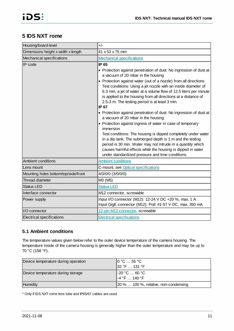
5 IDS NXT rome
Housing/board-level +/-
Dimensions height x width x length 41 x 53 x 75 mm
Mechanical specifications Mechanical specifications
IP code IP 65
· Protection against penetration of dust: No ingression of dust at
a vacuum of 20 mbar in the housing
· Protection against water (out of a nozzle) from all directions
Test conditions: Using a jet nozzle with an inside diameter of
6.3 mm, a jet of water at a volume flow of 12.5 liters per minute
is applied to the housing from all directions at a distance of
2.5-3 m. The testing period is at least 3 min.
IP 67
· Protection against penetration of dust: No ingression of dust at
a vacuum of 20 mbar in the housing
· Protection against ingress of water in case of temporary
immersion
Test conditions: The housing is dipped completely under water
in a dip tank. The submerged depth is 1 m and the testing
period is 30 min. Water may not intrude in a quantity which
causes harmful effects while the housing is dipped in water
under standardized pressure and time conditions.
Ambient conditions Ambient conditions
Lens mount C-mount, see Optical specifications
Mounting holes bottom/top/side/front 4/0/0/0 (3/0/0/0)
Thread diameter M3 (M5)
Status LED Status LED
Interface connector M12 connector, screwable
Power supply Input I/O connector (M12): 12-24 V DC +20 %, max. 1 A
Input GigE connector (M12): PoE 41-57 V DC, max. 350 mA
I/O connector 12-pin M12 connector, screwable
Electrical specifications Electrical specifications
5.1 Ambient conditions
The temperature values given below refer to the outer device temperature of the camera housing. The
temperature inside of the camera housing is generally higher than the outer temperature and may be up to
70 °C (158 °F).
Device temperature during operation 0 °C … 55 °C
32 °F … 131 °F
Device temperature during storage -20 °C … 60 °C
-4 °F … 140 °F
Humidity 20 % … 100 %, relative, non-condensing
* Only if IDS NXT rome lens tube and IP65/67 cables are used
2021-11-08 12
IDS NXT: Technical manual IDS NXT rome
Non-condensing means that the relative air humidity must be below 100 %. Otherwise, moisture will form on
the camera surface. If, for example, air has a relative humidity of 40 % at 35 °C (95 °F), the relative humidity
will increase to over 100 % if the air cools down to 19.5 °C (67 °F); condensation begins to form.
CAUTION! As the camera housing may get hot depending on the operating conditions there
may be risk of burns. Provide sufficient heat dissipation so that the housing temperature does
not exceed 55 °C (131 °F).
Notes on ambient conditions
· Avoid high air humidity levels and rapid temperature changes when using IDS cameras.
· Temperatures below +4 °C (39 °F) combined with excessive relative air humidity levels can cause icing.
Provide sufficient heat dissipation so that the specified device temperature is not exceeded during operation.
In general, the following recommendations apply:
· For a passive heat dissipation, mount the camera on a thermally-conductive surface like a metal plate or a
heat sink.
· If necessary, provide an active cooling for example by means of a fan.
With increasing device temperatures, the image quality could be reduced due to thermal noise. It is
recommended to mount the camera to a heat-dissipating unit even if the camera is operated below the
maximum specified temperature.
Vibration and shock resistance
Vibration and shock resistance of the cameras were tested as specified in EN 60068-2-6 and EN 60068-2-27.
Test parameter EN 60068-2-6 "Environmental testing - Tests: Vibration"
· Vibration mode: Sinus
· Lower frequency: 30 Hz
· Upper frequency: 500 Hz
· Acceleration: 10 g
· Throughput speed: 1 octave/minute, logarithmic
· Number of frequency cycles: 10 per axis
Test parameter EN 60068-2-27 "Environmental testing - Tests: Shock"
· Shock form: half sine
· Pulse duration: 1,9 ms
· Peak acceleration: 80 g
· Number of shocks per direction: 3 (± X, ±Y, ±Z)
· Shock form: half sine
· Pulse duration: 6 ms
· Peak acceleration: 25 g
· Number of shocks per direction: 100 (± X, ±Y, ±Z)
2021-11-08 13
IDS NXT: Technical manual IDS NXT rome
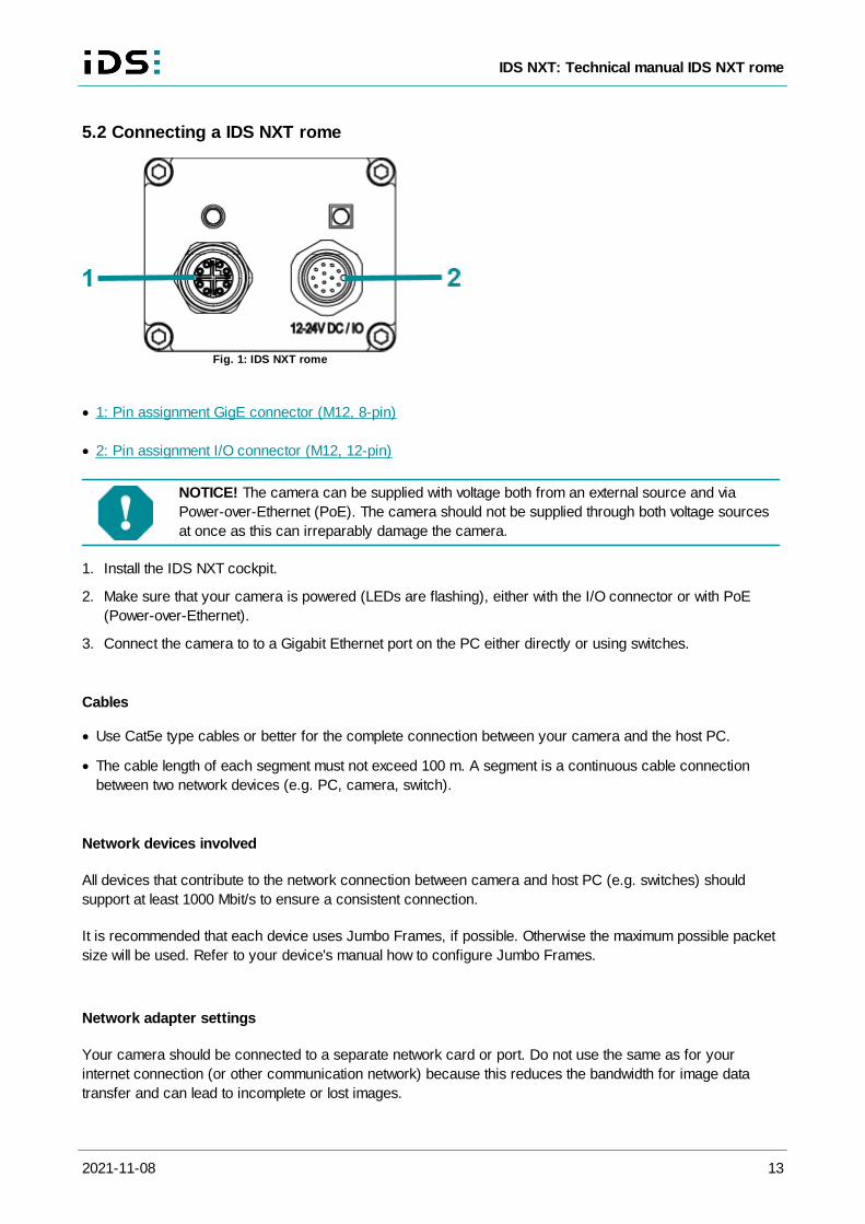
5.2 Connecting a IDS NXT rome
Fig. 1: IDS NXT rome
· 1: Pin assignment GigE connector (M12, 8-pin)
· 2: Pin assignment I/O connector (M12, 12-pin)
NOTICE! The camera can be supplied with voltage both from an external source and via
Power-over-Ethernet (PoE). The camera should not be supplied through both voltage sources
at once as this can irreparably damage the camera.
1. Install the IDS NXT cockpit.
2. Make sure that your camera is powered (LEDs are flashing), either with the I/O connector or with PoE
(Power-over-Ethernet).
3. Connect the camera to to a Gigabit Ethernet port on the PC either directly or using switches.
Cables
· Use Cat5e type cables or better for the complete connection between your camera and the host PC.
· The cable length of each segment must not exceed 100 m. A segment is a continuous cable connection
between two network devices (e.g. PC, camera, switch).
Network devices involved
All devices that contribute to the network connection between camera and host PC (e.g. switches) should
support at least 1000 Mbit/s to ensure a consistent connection.
It is recommended that each device uses Jumbo Frames, if possible. Otherwise the maximum possible packet
size will be used. Refer to your device's manual how to configure Jumbo Frames.
Network adapter settings
Your camera should be connected to a separate network card or port. Do not use the same as for your
internet connection (or other communication network) because this reduces the bandwidth for image data
transfer and can lead to incomplete or lost images.
2021-11-08 14
IDS NXT: Technical manual IDS NXT rome
To ensure optimum performance of the network connection, you need to install the latest drivers for your
network card.
The transfer rate of GigE network adapters for PCI slots is limited to approximately 110-120 MByte/s. USB
Ethernet adapter can have different restrictions, depending on the model.
For operating IDS NXT cameras, it is recommended:
· Maximize the receive buffer size or stack buffer size.
· Enable Jumbo Frames.
2021-11-08 15
IDS NXT: Technical manual IDS NXT rome
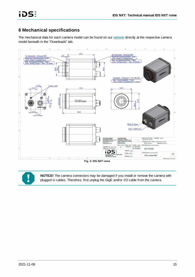
6 Mechanical specifications
The mechanical data for each camera model can be found on our website directly at the respective camera
model beneath in the "Downloads" tab.
Fig. 2: IDS NXT rome
NOTICE! The camera connectors may be damaged if you install or remove the camera with
plugged in cables. Therefore, first unplug the GigE and/or I/O cable from the camera.
2021-11-08 16
IDS NXT: Technical manual IDS NXT rome
7 Electrial specifications
Pin assignment GigE connector (M12)
Pin assignment I/O connector
Digital input wiring
Digital output wiring
RS-232 wiring
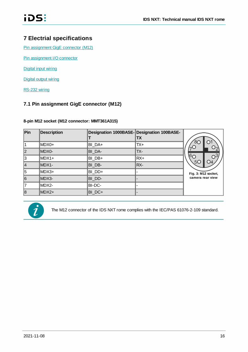
7.1 Pin assignment GigE connector (M12)
8-pin M12 socket (M12 connector: MMT361A315)
Pin Description Designation 1000BASE-
T
Designation 100BASE-
TX
Fig. 3: M12 socket,camera rear view
1 MDX0+ BI_DA+ TX+
2 MDX0- BI_DA- TX-
3 MDX1+ BI_DB+ RX+
4 MDX1- BI_DB- RX-
5 MDX3+ BI_DD+ -
6 MDX3- BI_DD- -
7 MDX2- BI-DC- -
8 MDX2+ BI_DC+ -
The M12 connector of the IDS NXT rome complies with the IEC/PAS 61076-2-109 standard.
2021-11-08 17
IDS NXT: Technical manual IDS NXT rome
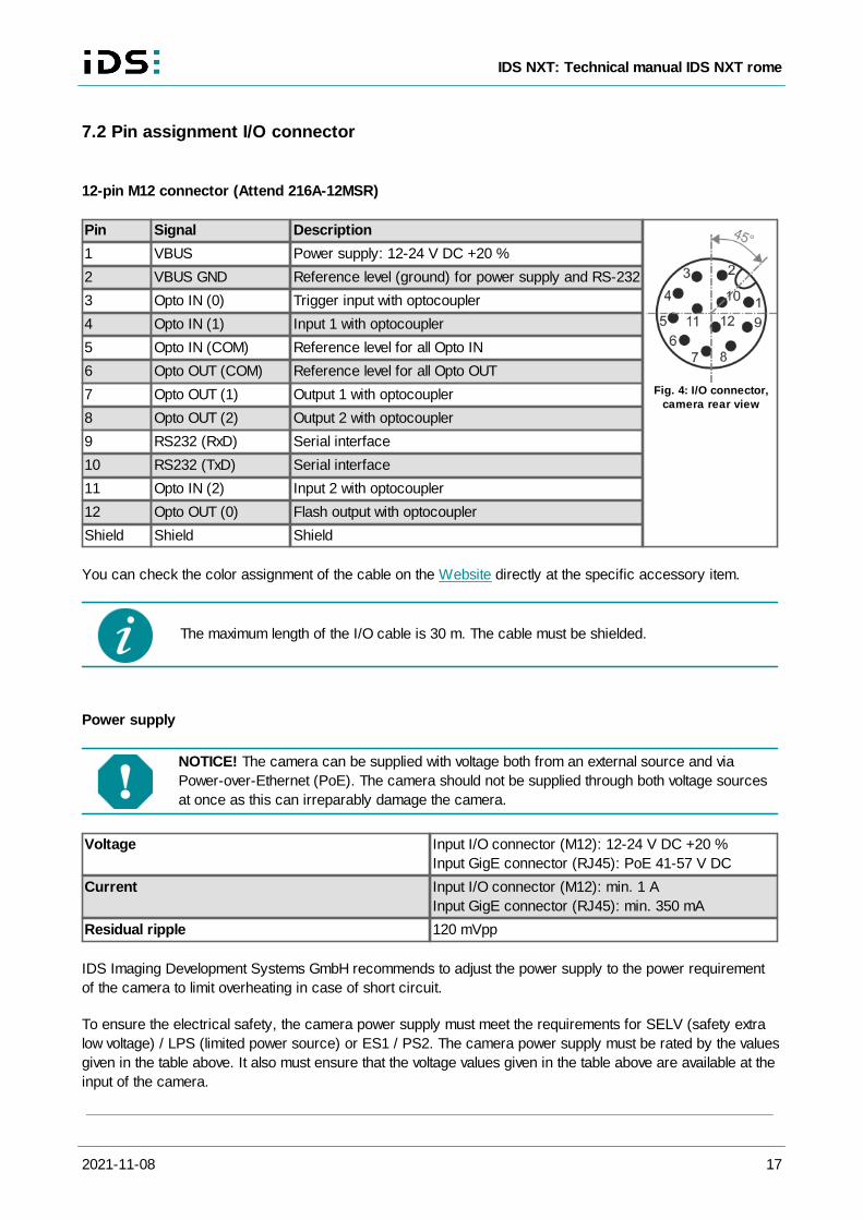
7.2 Pin assignment I/O connector
12-pin M12 connector (Attend 216A-12MSR)
Pin Signal Description
Fig. 4: I/O connector,camera rear view
1 VBUS Power supply: 12-24 V DC +20 %
2 VBUS GND Reference level (ground) for power supply and RS-232
3 Opto IN (0) Trigger input with optocoupler
4 Opto IN (1) Input 1 with optocoupler
5 Opto IN (COM) Reference level for all Opto IN
6 Opto OUT (COM) Reference level for all Opto OUT
7 Opto OUT (1) Output 1 with optocoupler
8 Opto OUT (2) Output 2 with optocoupler
9 RS232 (RxD) Serial interface
10 RS232 (TxD) Serial interface
11 Opto IN (2) Input 2 with optocoupler
12 Opto OUT (0) Flash output with optocoupler
Shield Shield Shield
You can check the color assignment of the cable on the Website directly at the specific accessory item.
The maximum length of the I/O cable is 30 m. The cable must be shielded.
Power supply
NOTICE! The camera can be supplied with voltage both from an external source and via
Power-over-Ethernet (PoE). The camera should not be supplied through both voltage sources
at once as this can irreparably damage the camera.
Voltage Input I/O connector (M12): 12-24 V DC +20 %
Input GigE connector (RJ45): PoE 41-57 V DC
Current Input I/O connector (M12): min. 1 A
Input GigE connector (RJ45): min. 350 mA
Residual ripple 120 mVpp
IDS Imaging Development Systems GmbH recommends to adjust the power supply to the power requirement
of the camera to limit overheating in case of short circuit.
To ensure the electrical safety, the camera power supply must meet the requirements for SELV (safety extra
low voltage) / LPS (limited power source) or ES1 / PS2. The camera power supply must be rated by the values
given in the table above. It also must ensure that the voltage values given in the table above are available at the
input of the camera.
2021-11-08 18
IDS NXT: Technical manual IDS NXT rome
Avis pour le Canada:
IDS Imaging Development Systems GmbH recommande d'adapter l'alimentation électrique aux besoins de
la caméra afin de limiter la surchauffe en cas de court-circuit.
Pour garantir la sécurité électrique, l'alimentation de la caméra doit être conforme aux exigences de
sécurité SELV (très basse tension de sécurité)/LPS (source à puissance limitée) ou ES1/PS2.
L'alimentation de la caméra doit respecter les valeurs indiquées dans le tableau ci-dessus. Elle doit
également répondre au fait que les tensions indiquées dans le tableau ci-dessus sont présentes à l'entrée
de la caméra.
Information on the power consumption of individual camera models can be found in the model data sheet.
Keep in mind that a voltage drop will occur when you use long cables for power supply to the
camera. Choose the size of the cable in such a way that the supply voltage available at the
input of the camera is at least 12 V.
To supply the IDS NXT rome camera with power using PoE or PoE+, you can use PoE
injectors or switches that are compatible with IEEE standard 802.3af or IEEE standard
802.at.
7.3 Digital input wiring
Symbol Minimum Typical Maximum Unit
Input low range VIL 0 0 1 V
Input high range VIH 5 - 24 V
Voltage range 0 - 30 V
Input leakage current II - - - µ A
Trigger edge steepness 35 - - V/ms
Trigger pulse width (edge) 10 - - µ s
For interpreting the trigger signal, either the rising or the falling edge can be used. The digital inputs are
galvanically isolated using optocouplers to protect the device and the PC against surges. Only DC voltages
may be applied to the digital inputs.
2021-11-08 19
IDS NXT: Technical manual IDS NXT rome
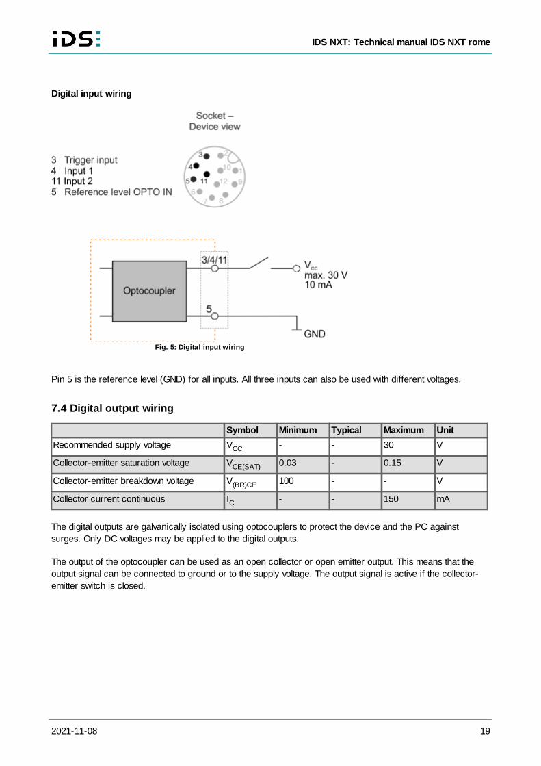
Digital input wiring
Fig. 5: Digital input wiring
Pin 5 is the reference level (GND) for all inputs. All three inputs can also be used with different voltages.
7.4 Digital output wiring
Symbol Minimum Typical Maximum Unit
Recommended supply voltage VCC - - 30 V
Collector-emitter saturation voltage VCE(SAT) 0.03 - 0.15 V
Collector-emitter breakdown voltage V(BR)CE 100 - - V
Collector current continuous IC - - 150 mA
The digital outputs are galvanically isolated using optocouplers to protect the device and the PC against
surges. Only DC voltages may be applied to the digital outputs.
The output of the optocoupler can be used as an open collector or open emitter output. This means that the
output signal can be connected to ground or to the supply voltage. The output signal is active if the collector-
emitter switch is closed.
2021-11-08 20
IDS NXT: Technical manual IDS NXT rome
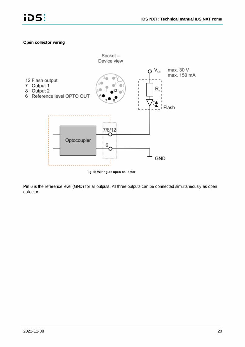
Open collector wiring
Fig. 6: Wiring as open collector
Pin 6 is the reference level (GND) for all outputs. All three outputs can be connected simultaneously as open
collector.
2021-11-08 21
IDS NXT: Technical manual IDS NXT rome
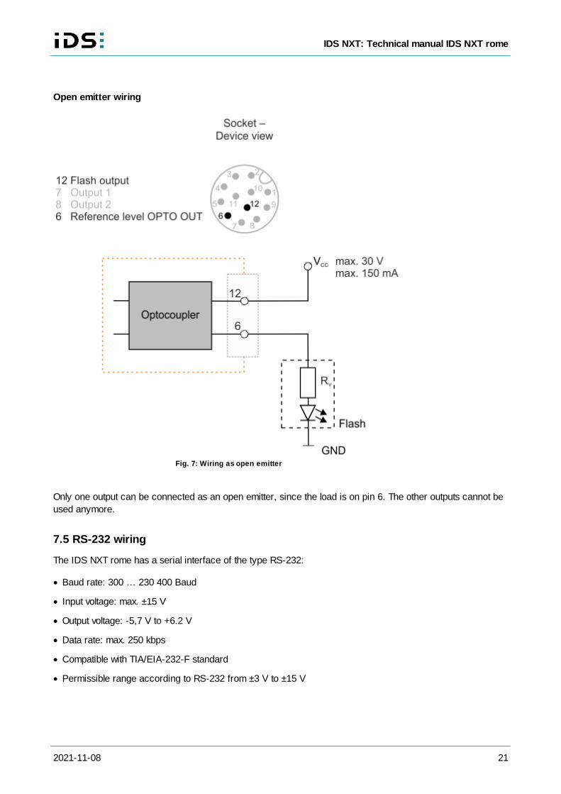
Open emitter wiring
Fig. 7: Wiring as open emitter
Only one output can be connected as an open emitter, since the load is on pin 6. The other outputs cannot be
used anymore.
7.5 RS-232 wiring
The IDS NXT rome has a serial interface of the type RS-232:
· Baud rate: 300 … 230 400 Baud
· Input voltage: max. ±15 V
· Output voltage: -5,7 V to +6.2 V
· Data rate: max. 250 kbps
· Compatible with TIA/EIA-232-F standard
· Permissible range according to RS-232 from ±3 V to ±15 V
2021-11-08 22
IDS NXT: Technical manual IDS NXT rome
The data rate of the serial interface depends on the capacity and length of the cable.
2021-11-08 23
IDS NXT: Technical manual IDS NXT rome
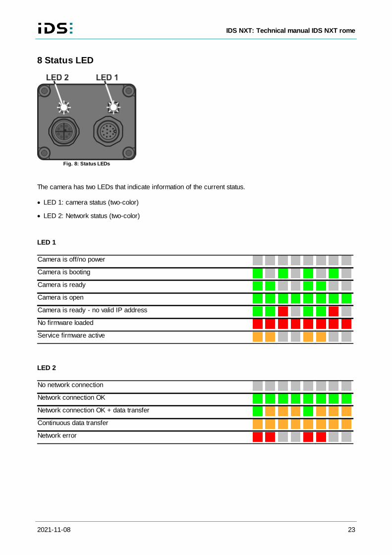
8 Status LED
Fig. 8: Status LEDs
The camera has two LEDs that indicate information of the current status.
· LED 1: camera status (two-color)
· LED 2: Network status (two-color)
LED 1
Camera is off/no power
Camera is booting
Camera is ready
Camera is open
Camera is ready - no valid IP address
No firmware loaded
Service firmware active
LED 2
No network connection
Network connection OK
Network connection OK + data transfer
Continuous data transfer
Network error
2021-11-08 24
IDS NXT: Technical manual IDS NXT rome
9 Optical specifications
Immersion depth for lenses
Position accuracy of the sensor
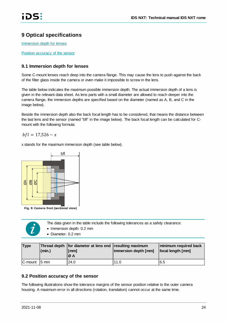
9.1 Immersion depth for lenses
Some C-mount lenses reach deep into the camera flange. This may cause the lens to push against the back
of the filter glass inside the camera or even make it impossible to screw in the lens.
The table below indicates the maximum possible immersion depth. The actual immersion depth of a lens is
given in the relevant data sheet. As lens parts with a small diameter are allowed to reach deeper into the
camera flange, the immersion depths are specified based on the diameter (named as A, B, and C in the
image below).
Beside the immersion depth also the back focal length has to be considered, that means the distance between
the last lens and the sensor (named "bfl" in the image below). The back focal length can be calculated for C-
mount with the following formula:
x stands for the maximum immersion depth (see table below).
Fig. 9: Camera front (sectional view)
The data given in the table include the following tolerances as a safety clearance:
· Immersion depth: 0.2 mm
· Diameter: 0.2 mm
Type Thread depth
(min.)
for diameter at lens end
[mm]
Ø A
resulting maximum
immersion depth [mm]
minimum required back
focal length [mm]
C-mount 5 mm 24.0 11.0 6.5
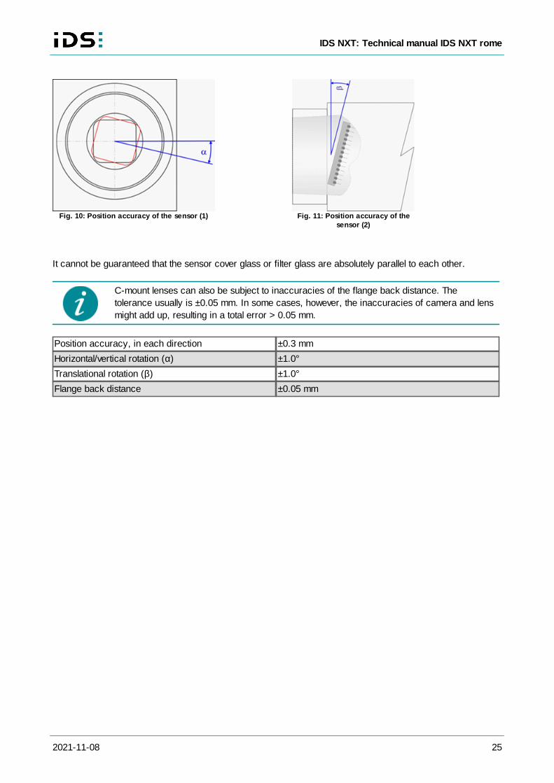
9.2 Position accuracy of the sensor
The following illustrations show the tolerance margins of the sensor position relative to the outer camera
housing. A maximum error in all directions (rotation, translation) cannot occur at the same time.
2021-11-08 25
IDS NXT: Technical manual IDS NXT rome
Fig. 10: Position accuracy of the sensor (1) Fig. 11: Position accuracy of thesensor (2)
It cannot be guaranteed that the sensor cover glass or filter glass are absolutely parallel to each other.
C-mount lenses can also be subject to inaccuracies of the flange back distance. The
tolerance usually is ±0.05 mm. In some cases, however, the inaccuracies of camera and lens
might add up, resulting in a total error > 0.05 mm.
Position accuracy, in each direction ±0.3 mm
Horizontal/vertical rotation (α) ±1.0°
Translational rotation (β) ±1.0°
Flange back distance ±0.05 mm
2021-11-08 26
IDS NXT: Technical manual IDS NXT rome
10 Filter glasses
Filter types
Cleaning the filter glasses
10.1 Filter types
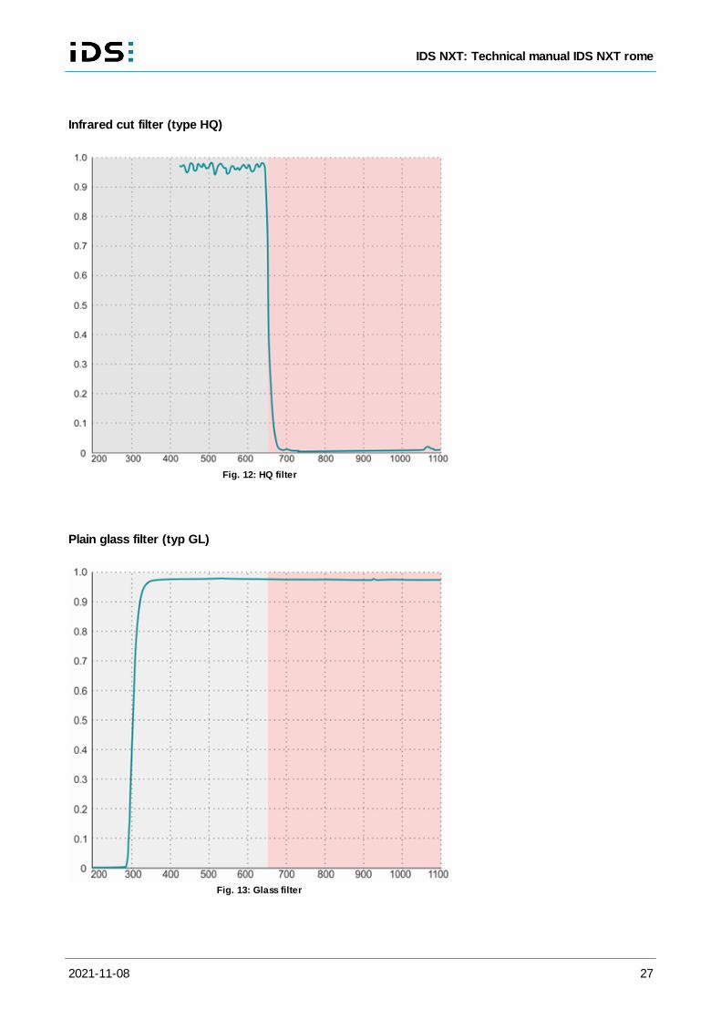
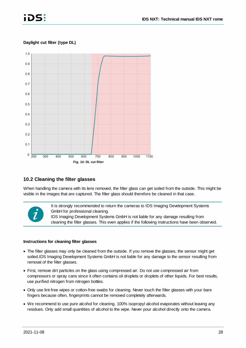
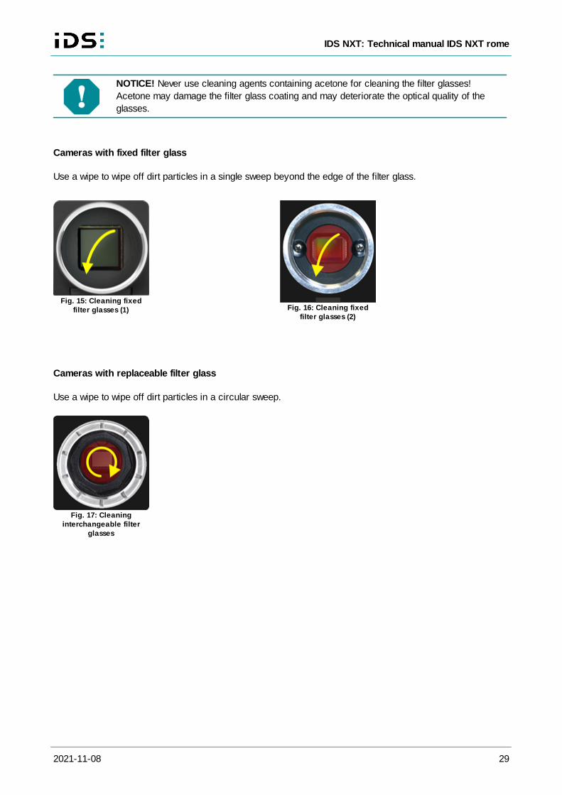
Every camera has a filter glass in the front flange to prevent the entry of dust particles. Color cameras by
default use an IR cut filter (type HQ), which is required to ensure correct color rendering. For monochrome
cameras, the standard filter is a glass filter (type GL). Every camera model is available with different filter
variants such as daylight cut filters (type DL). The filter type is given at the end of the model name.
The following table shows an overview of the different optical filters used in IDS cameras:
Filter type Name
Refractive
index
(nFilter) Glass type
Thickness
(f)
Cut-on
wavelength
Cut-off
wavelength
Non-
reflective
IR cut filter HQ 1.53 D263 1 mm - 650 ±10 nm On one side
GlassGL 1.53 D263T 1 mm 330 nm -
On both
sides
Daylight cut
filterDL 1.53 RG695 1 mm 695 nm - -
You can tell the filter type from the outside by its coloration:
· Reddish glass: HQ filter
· Plain glass: GL filter
· Opaque glass: DL filter
All sensors have a cover glass. The transmission of the cover glass is taken into account in
the camera data sheet.
2021-11-08 27
IDS NXT: Technical manual IDS NXT rome
Infrared cut filter (type HQ)
Fig. 12: HQ filter
Plain glass filter (typ GL)
Fig. 13: Glass filter
2021-11-08 28
IDS NXT: Technical manual IDS NXT rome
Daylight cut filter (type DL)
Fig. 14: DL cut filter
10.2 Cleaning the filter glasses
When handling the camera with its lens removed, the filter glass can get soiled from the outside. This might be
visible in the images that are captured. The filter glass should therefore be cleaned in that case.
It is strongly recommended to return the cameras to IDS Imaging Development Systems
GmbH for professional cleaning.
IDS Imaging Development Systems GmbH is not liable for any damage resulting from
cleaning the filter glasses. This even applies if the following instructions have been observed.
Instructions for cleaning filter glasses
· The filter glasses may only be cleaned from the outside. If you remove the glasses, the sensor might get
soiled.IDS Imaging Development Systems GmbH is not liable for any damage to the sensor resulting from
removal of the filter glasses.
· First, remove dirt particles on the glass using compressed air. Do not use compressed air from
compressors or spray cans since it often contains oil droplets or droplets of other liquids. For best results,
use purified nitrogen from nitrogen bottles.
· Only use lint-free wipes or cotton-free swabs for cleaning. Never touch the filter glasses with your bare
fingers because often, fingerprints cannot be removed completely afterwards.
· We recommend to use pure alcohol for cleaning. 100% isopropyl alcohol evaporates without leaving any
residues. Only add small quantities of alcohol to the wipe. Never pour alcohol directly onto the camera.
2021-11-08 29
IDS NXT: Technical manual IDS NXT rome
NOTICE! Never use cleaning agents containing acetone for cleaning the filter glasses!
Acetone may damage the filter glass coating and may deteriorate the optical quality of the
glasses.
Cameras with fixed filter glass
Use a wipe to wipe off dirt particles in a single sweep beyond the edge of the filter glass.
Fig. 15: Cleaning fixedfilter glasses (1) Fig. 16: Cleaning fixed
filter glasses (2)
Cameras with replaceable filter glass
Use a wipe to wipe off dirt particles in a circular sweep.
Fig. 17: Cleaninginterchangeable filter
glasses
2021-11-08 30
IDS NXT: Technical manual IDS NXT rome
11 System specification
CPU 1.3 GHz Dual Core ARM Cortex-A53
FPGA Xilinx Zynq UltraScale+ (ZU3CG)
RAM 2 GB DDR4
Flash 8 GB (with the system)
11.1 CNN
Operating system Linux
Image preprocessing· Demosaicing
· AOI
· Resolution scaling
· CNN preprocessing modes
o zeroto255
o zerotoone
· CNN preprocessing modes from
keras.applications.imagenet_utils.preprocess_input
o tf
o caffe
o torch
Data postprocessing on CPU· Softmax operation for classification
· Box regression for object detection
· User programmable processing on Dual Core ARM Cortex-A53
11.1.1 deep ocean core
Input data formats· Up to 512 x 512 pixels
· Tensor of shape (x, y, 3) for color
· Tensor of shape (x, y, 1) for mono
Output data formats· Float
· Shape formating can be defined in post-processing (depending on
model and task)
Internal number format· 16-bit fixed point
· Integer and fractional bits individually optimized for each layer
Maximum number of layers in
model· 180 layers
Maximum model size Any size fitting the RAM size (maximum 245 MB (1,6 MP mono),
minimum 160 MB (6 MP color)
Supported operations/layers· 2D convolution layer
· Depthwise separable convolution layer
· Average pooling layer
· Max. pooling layer
· Dense layer
· Add layer
· Concatenate layer
2021-11-08 31
IDS NXT: Technical manual IDS NXT rome
· Squeeze-and-Excitation layer
· ReLU activation
· ReLU6 activation
· Swish activation
· Sigmoid activation
· Batch normalization
Filter kernel/pooling parameters· Kernel/pooling window: any rectangle up to 15 x 15 pixels
· Kernel depth: any depth
· Kernel/pooling stride: up to 15 pixels
Inference time See Benchmark
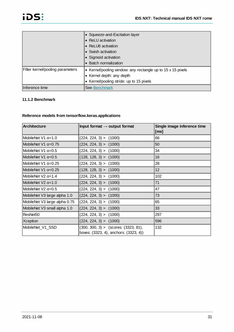
11.1.2 Benchmark
Reference models from tensorflow.keras.applications
Architecture Input format output format Single image inference time
[ms]
MobileNet V1 α=1.0 (224, 224, 3) > (1000) 66
MobileNet V1 α=0.75 (224, 224, 3) > (1000) 50
MobileNet V1 α=0.5 (224, 224, 3) > (1000) 34
MobileNet V1 α=0.5 (128, 128, 3) > (1000) 16
MobileNet V1 α=0.25 (224, 224, 3) > (1000) 28
MobileNet V1 α=0.25 (128, 128, 3) > (1000) 12
MobileNet V2 α=1.4 (224, 224, 3) > (1000) 102
MobileNet V2 α=1.0 (224, 224, 3) > (1000) 71
MobileNet V2 α=0.5 (224, 224, 3) > (1000) 47
MobileNet V3 large alpha 1.0 (224, 224, 3) > (1000) 73
MobileNet V3 large alpha 0.75 (224, 224, 3) > (1000) 65
MobileNet V3 small alpha 1.0 (224, 224, 3) > (1000) 33
ResNet50 (224, 224, 3) > (1000) 297
Xception (224, 224, 3) > (1000) 596
MobileNet_V1_SSD (300, 300, 3) > (scores: (3323, 81),
boxes: (3323, 4), anchors: (3323, 4))
132
2021-11-08 32
IDS NXT: Technical manual IDS NXT rome
- A -
Accelerator 30
Ambient conditions 11
Architecture 31
- B -
Benchmark 31
- C -
Contact 3
CPU 30
- D -
Daylight cut filter 26
Dimensions 15
Directive 9
- E -
ESD 6
- F -
Filter glass 26
clean 28
type 26
Flash 19
- G -
GigE connector 16
- H -
Housing version 15
- I -
I/O connector 17
Immersion depth
lens 24
Inference time 30, 31
Infrared cut filter 26
Input
digital 18
Interface
RS-232 21
- L -
Layer
count 30
- M -
M12 16
- N -
Network
cable 13
card 13
- O -
Operating system 30
Output
digital 19
- P -
Pin assigment 17
Plain glass filter 26
- R -
RAM 30
RS-232
baud rate 21
- S -
Safety 6
Sensor
position accuracy 24
Specification
AI 30
camera 11
electrical 16
optical 24
Standard 9
Status LED 23
System 30
- T -
Trigger 18
- U -
Use
intended 6
Related Documents


