RATE TOTAL AMOUNT $/ut $ LV CABLE BOQ 1 Supply of single conductor 0,6/1 kV 1x12 AWG copper conductor RHW-2. According to the characteristics defined in the specification and in the data sheets. Included transport, storage, connections, proportional part of electrical material to achieve the installation. - 0 2 Supply of single conductor 0,6/1 kV 1x10 AWG copper conductor RHW-2. According to the characteristics defined in the specification and in the data sheets. Included transport, storage, connections, proportional part of electrical material to achieve the installation. - 0 3 Supply of single conductor 0,6/1 kV 1x8 AWG copper conductor RHW-2. According to the characteristics defined in the specification and in the data sheets. Included transport, storage, connections, proportional part of electrical material to achieve the installation. - 0 4 Supply of single conductor 0,6/1 kV 1x6 AWG copper conductor RHW-2. According to the characteristics defined in the specification and in the data sheets. Included transport, storage, connections, proportional part of electrical material to achieve the installation. - 215 5 Supply of single conductor 0,6/1 kV 1x4 AWG copper conductor RHW-2. According to the characteristics defined in the specification and in the data sheets. Included transport, storage, connections, proportional part of electrical material to achieve the installation. - 315 6 Supply of single conductor 0,6/1 kV 1x3 AWG copper conductor RHW-2. According to the characteristics defined in the specification and in the data sheets. Included transport, storage, connections, proportional part of electrical material to achieve the installation. - 235 6.1 Supply of single conductor 0,6/1 kV 1x2 AWG copper conductor RHW-2. According to the characteristics defined in the specification and in the data sheets. Included transport, storage, connections, proportional part of electrical material to achieve the installation. - 570 7 Supply of single conductor 0,6/1 kV 1x1 AWG copper conductor RHW-2. According to the characteristics defined in the specification and in the data sheets. Included transport, storage, connections, proportional part of electrical material to achieve the installation. - 275 8 Supply of single conductor 0,6/1 kV 1x1/0 AWG copper conductor RHW-2. According to the characteristics defined in the specification and in the data sheets. Included transport, storage, connections, proportional part of electrical material to achieve the installation. - 2200 8.1 Supply of single conductor 0,6/1 kV 1x2/0 AWG copper conductor RHW-2. According to the characteristics defined in the specification and in the data sheets. Included transport, storage, connections, proportional part of electrical material to achieve the installation. - 900 8.1 Supply of single conductor 0,6/1 kV 1x3/0 AWG copper conductor RHW-2. According to the characteristics defined in the specification and in the data sheets. Included transport, storage, connections, proportional part of electrical material to achieve the installation. - 550 9 Supply of single conductor 0,6/1 kV 1x4/0 AWG copper conductor RHW-2. According to the characteristics defined in the specification and in the data sheets. Included transport, storage, connections, proportional part of electrical material to achieve the installation. - 1060 9.1 Supply of single conductor 0,6/1 kV 1x250 AWG copper conductor RHW-2. According to the characteristics defined in the specification and in the data sheets. Included transport, storage, connections, proportional part of electrical material to achieve the installation. - 640 10 Supply of single conductor 0,6/1 kV 1x350 AWG copper conductor RHW-2. According to the characteristics defined in the specification and in the data sheets. Included transport, storage, connections, proportional part of electrical material to achieve the installation. - 660 10.1 Supply of single conductor 0,6/1 kV 1x500 AWG copper conductor RHW-2. According to the characteristics defined in the specification and in the data sheets. Included transport, storage, connections, proportional part of electrical material to achieve the installation. - 140 10.2 Supply of multi-conductor 0,6/1 kV (3 phases + Neutral + Grounding) 12 AWG copper conductor RHW-2. According to the characteristics defined in the specification and in the data sheets. Included transport, storage, connections, proportional part of electrical material to achieve the installation. - 615 10.3 Supply of multi-conductor 0,6/1 kV (3 phases + Neutral + Grounding) 10 AWG copper conductor RHW-2. According to the characteristics defined in the specification and in the data sheets. Included transport, storage, connections, proportional part of electrical material to achieve the installation. - 1345 10.4 Supply of multi-conductor 0,6/1 kV (3 phases + Neutral + Grounding) 8 AWG copper conductor RHW-2. According to the characteristics defined in the specification and in the data sheets. Included transport, storage, connections, proportional part of electrical material to achieve the installation. - 615 10.5 Supply of multi-conductor 0,6/1 kV (3 phases + Neutral + Grounding) 6 AWG copper conductor RHW-2. According to the characteristics defined in the specification and in the data sheets. Included transport, storage, connections, proportional part of electrical material to achieve the installation. - 150 10.6 Supply of multi-conductor 0,6/1 kV (3 phases + Neutral + Grounding) 4 AWG copper conductor RHW-2. According to the characteristics defined in the specification and in the data sheets. Included transport, storage, connections, proportional part of electrical material to achieve the installation. - 225 10.7 Supply of multi-conductor 0,6/1 kV (3 phases + Neutral + Grounding) 3 AWG copper conductor RHW-2. According to the characteristics defined in the specification and in the data sheets. Included transport, storage, connections, proportional part of electrical material to achieve the installation. - 120 10.8 Supply of multi-conductor 0,6/1 kV (3 phases + Neutral + Grounding) 2 AWG copper conductor RHW-2. According to the characteristics defined in the specification and in the data sheets. Included transport, storage, connections, proportional part of electrical material to achieve the installation. - 100 Item Description Cable Code Qty. Unit or feet-inch Written: J. Antonio Acosta Revised: Javier Ariño Project Manager: Gaizka Murga Principal: Tom Lorentz Date: Dec 9th 2014 Enclosure Design Services for the Advanced Technology Solar Telescope (ATST) IDOM Doc. N: 15812-BOQ-155-9 Issue BILL OF QUANTITIES OF ELECTRICAL EQUIPMENT 9

Welcome message from author
This document is posted to help you gain knowledge. Please leave a comment to let me know what you think about it! Share it to your friends and learn new things together.
Transcript

RATE TOTAL AMOUNT
$/ut $
LV CABLE BOQ
1
Supply of single conductor 0,6/1 kV 1x12 AWG copper conductor RHW-2.
According to the characteristics defined in the specification and in the data sheets.
Included transport, storage, connections, proportional part of electrical material to
achieve the installation.
- 0
2
Supply of single conductor 0,6/1 kV 1x10 AWG copper conductor RHW-2.
According to the characteristics defined in the specification and in the data sheets.
Included transport, storage, connections, proportional part of electrical material to
achieve the installation.
- 0
3
Supply of single conductor 0,6/1 kV 1x8 AWG copper conductor RHW-2.
According to the characteristics defined in the specification and in the data sheets.
Included transport, storage, connections, proportional part of electrical material to
achieve the installation.
- 0
4
Supply of single conductor 0,6/1 kV 1x6 AWG copper conductor RHW-2.
According to the characteristics defined in the specification and in the data sheets.
Included transport, storage, connections, proportional part of electrical material to
achieve the installation.
- 215
5
Supply of single conductor 0,6/1 kV 1x4 AWG copper conductor RHW-2.
According to the characteristics defined in the specification and in the data sheets.
Included transport, storage, connections, proportional part of electrical material to
achieve the installation.
- 315
6
Supply of single conductor 0,6/1 kV 1x3 AWG copper conductor RHW-2.
According to the characteristics defined in the specification and in the data sheets.
Included transport, storage, connections, proportional part of electrical material to
achieve the installation.
- 235
6.1
Supply of single conductor 0,6/1 kV 1x2 AWG copper conductor RHW-2.
According to the characteristics defined in the specification and in the data sheets.
Included transport, storage, connections, proportional part of electrical material to
achieve the installation.
- 570
7
Supply of single conductor 0,6/1 kV 1x1 AWG copper conductor RHW-2.
According to the characteristics defined in the specification and in the data sheets.
Included transport, storage, connections, proportional part of electrical material to
achieve the installation.
- 275
8
Supply of single conductor 0,6/1 kV 1x1/0 AWG copper conductor RHW-2.
According to the characteristics defined in the specification and in the data sheets.
Included transport, storage, connections, proportional part of electrical material to
achieve the installation.
- 2200
8.1
Supply of single conductor 0,6/1 kV 1x2/0 AWG copper conductor RHW-2.
According to the characteristics defined in the specification and in the data sheets.
Included transport, storage, connections, proportional part of electrical material to
achieve the installation.
- 900
8.1
Supply of single conductor 0,6/1 kV 1x3/0 AWG copper conductor RHW-2.
According to the characteristics defined in the specification and in the data sheets.
Included transport, storage, connections, proportional part of electrical material to
achieve the installation.
- 550
9
Supply of single conductor 0,6/1 kV 1x4/0 AWG copper conductor RHW-2.
According to the characteristics defined in the specification and in the data sheets.
Included transport, storage, connections, proportional part of electrical material to
achieve the installation.
- 1060
9.1
Supply of single conductor 0,6/1 kV 1x250 AWG copper conductor RHW-2.
According to the characteristics defined in the specification and in the data sheets.
Included transport, storage, connections, proportional part of electrical material to
achieve the installation.
- 640
10
Supply of single conductor 0,6/1 kV 1x350 AWG copper conductor RHW-2.
According to the characteristics defined in the specification and in the data sheets.
Included transport, storage, connections, proportional part of electrical material to
achieve the installation.
- 660
10.1
Supply of single conductor 0,6/1 kV 1x500 AWG copper conductor RHW-2.
According to the characteristics defined in the specification and in the data sheets.
Included transport, storage, connections, proportional part of electrical material to
achieve the installation.
- 140
10.2
Supply of multi-conductor 0,6/1 kV (3 phases + Neutral + Grounding) 12 AWG
copper conductor RHW-2. According to the characteristics defined in the
specification and in the data sheets. Included transport, storage, connections,
proportional part of electrical material to achieve the installation.
- 615
10.3
Supply of multi-conductor 0,6/1 kV (3 phases + Neutral + Grounding) 10 AWG
copper conductor RHW-2. According to the characteristics defined in the
specification and in the data sheets. Included transport, storage, connections,
proportional part of electrical material to achieve the installation.
- 1345
10.4
Supply of multi-conductor 0,6/1 kV (3 phases + Neutral + Grounding) 8 AWG
copper conductor RHW-2. According to the characteristics defined in the
specification and in the data sheets. Included transport, storage, connections,
proportional part of electrical material to achieve the installation.
- 615
10.5
Supply of multi-conductor 0,6/1 kV (3 phases + Neutral + Grounding) 6 AWG
copper conductor RHW-2. According to the characteristics defined in the
specification and in the data sheets. Included transport, storage, connections,
proportional part of electrical material to achieve the installation.
- 150
10.6
Supply of multi-conductor 0,6/1 kV (3 phases + Neutral + Grounding) 4 AWG
copper conductor RHW-2. According to the characteristics defined in the
specification and in the data sheets. Included transport, storage, connections,
proportional part of electrical material to achieve the installation.
- 225
10.7
Supply of multi-conductor 0,6/1 kV (3 phases + Neutral + Grounding) 3 AWG
copper conductor RHW-2. According to the characteristics defined in the
specification and in the data sheets. Included transport, storage, connections,
proportional part of electrical material to achieve the installation.
- 120
10.8
Supply of multi-conductor 0,6/1 kV (3 phases + Neutral + Grounding) 2 AWG
copper conductor RHW-2. According to the characteristics defined in the
specification and in the data sheets. Included transport, storage, connections,
proportional part of electrical material to achieve the installation.
- 100
Item DescriptionCable
Code
Qty.
Unit or feet-inch
Written: J. Antonio Acosta
Revised: Javier Ariño
Project Manager: Gaizka Murga
Principal: Tom Lorentz
Date: Dec 9th 2014
Enclosure Design Services for the
Advanced Technology Solar Telescope (ATST)
IDOM Doc. N: 15812-BOQ-155-9
Issue
BILL OF QUANTITIES OF ELECTRICAL EQUIPMENT 9
RATE TOTAL AMOUNT
$/ut $Item Description
Cable
Code
Qty.
Unit or feet-inch
Written: J. Antonio Acosta
Revised: Javier Ariño
Project Manager: Gaizka Murga
Principal: Tom Lorentz
Date: Dec 9th 2014
Enclosure Design Services for the
Advanced Technology Solar Telescope (ATST)
IDOM Doc. N: 15812-BOQ-155-9
Issue
BILL OF QUANTITIES OF ELECTRICAL EQUIPMENT 9
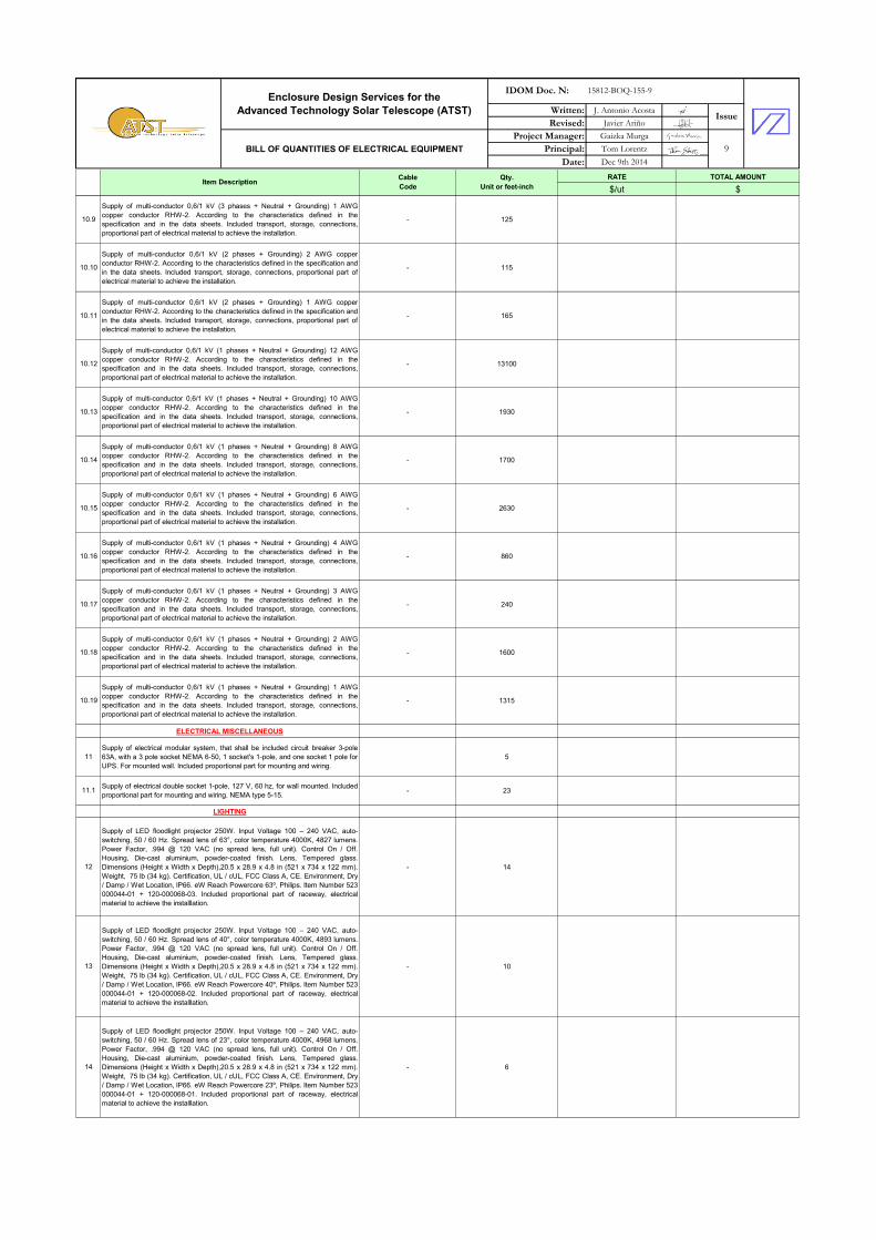
10.9
Supply of multi-conductor 0,6/1 kV (3 phases + Neutral + Grounding) 1 AWG
copper conductor RHW-2. According to the characteristics defined in the
specification and in the data sheets. Included transport, storage, connections,
proportional part of electrical material to achieve the installation.
- 125
10.10
Supply of multi-conductor 0,6/1 kV (2 phases + Grounding) 2 AWG copper
conductor RHW-2. According to the characteristics defined in the specification and
in the data sheets. Included transport, storage, connections, proportional part of
electrical material to achieve the installation.
- 115
10.11
Supply of multi-conductor 0,6/1 kV (2 phases + Grounding) 1 AWG copper
conductor RHW-2. According to the characteristics defined in the specification and
in the data sheets. Included transport, storage, connections, proportional part of
electrical material to achieve the installation.
- 165
10.12
Supply of multi-conductor 0,6/1 kV (1 phases + Neutral + Grounding) 12 AWG
copper conductor RHW-2. According to the characteristics defined in the
specification and in the data sheets. Included transport, storage, connections,
proportional part of electrical material to achieve the installation.
- 13100
10.13
Supply of multi-conductor 0,6/1 kV (1 phases + Neutral + Grounding) 10 AWG
copper conductor RHW-2. According to the characteristics defined in the
specification and in the data sheets. Included transport, storage, connections,
proportional part of electrical material to achieve the installation.
- 1930
10.14
Supply of multi-conductor 0,6/1 kV (1 phases + Neutral + Grounding) 8 AWG
copper conductor RHW-2. According to the characteristics defined in the
specification and in the data sheets. Included transport, storage, connections,
proportional part of electrical material to achieve the installation.
- 1700
10.15
Supply of multi-conductor 0,6/1 kV (1 phases + Neutral + Grounding) 6 AWG
copper conductor RHW-2. According to the characteristics defined in the
specification and in the data sheets. Included transport, storage, connections,
proportional part of electrical material to achieve the installation.
- 2630
10.16
Supply of multi-conductor 0,6/1 kV (1 phases + Neutral + Grounding) 4 AWG
copper conductor RHW-2. According to the characteristics defined in the
specification and in the data sheets. Included transport, storage, connections,
proportional part of electrical material to achieve the installation.
- 860
10.17
Supply of multi-conductor 0,6/1 kV (1 phases + Neutral + Grounding) 3 AWG
copper conductor RHW-2. According to the characteristics defined in the
specification and in the data sheets. Included transport, storage, connections,
proportional part of electrical material to achieve the installation.
- 240
10.18
Supply of multi-conductor 0,6/1 kV (1 phases + Neutral + Grounding) 2 AWG
copper conductor RHW-2. According to the characteristics defined in the
specification and in the data sheets. Included transport, storage, connections,
proportional part of electrical material to achieve the installation.
- 1600
10.19
Supply of multi-conductor 0,6/1 kV (1 phases + Neutral + Grounding) 1 AWG
copper conductor RHW-2. According to the characteristics defined in the
specification and in the data sheets. Included transport, storage, connections,
proportional part of electrical material to achieve the installation.
- 1315
ELECTRICAL MISCELLANEOUS
11
Supply of electrical modular system, that shall be included circuit breaker 3-pole
63A, with a 3 pole socket NEMA 6-50, 1 socket's 1-pole, and one socket 1 pole for
UPS. For mounted wall. Included proportional part for mounting and wiring.
5
11.1Supply of electrical double socket 1-pole, 127 V, 60 hz, for wall mounted. Included
proportional part for mounting and wiring. NEMA type 5-15.- 23
LIGHTING
12
Supply of LED floodlight projector 250W. Input Voltage 100 – 240 VAC, auto-
switching, 50 / 60 Hz. Spread lens of 63°, color temperature 4000K, 4827 lumens.
Power Factor, .994 @ 120 VAC (no spread lens, full unit). Control On / Off.
Housing, Die-cast aluminium, powder-coated finish. Lens, Tempered glass.
Dimensions (Height x Width x Depth),20.5 x 28.9 x 4.8 in (521 x 734 x 122 mm).
Weight, 75 lb (34 kg). Certification, UL / cUL, FCC Class A, CE. Environment, Dry
/ Damp / Wet Location, IP66. eW Reach Powercore 63º, Philips. Item Number 523-
000044-01 + 120-000068-03. Included proportional part of raceway, electrical
material to achieve the installlation.
- 14
13
Supply of LED floodlight projector 250W. Input Voltage 100 – 240 VAC, auto-
switching, 50 / 60 Hz. Spread lens of 40°, color temperature 4000K, 4893 lumens.
Power Factor, .994 @ 120 VAC (no spread lens, full unit). Control On / Off.
Housing, Die-cast aluminium, powder-coated finish. Lens, Tempered glass.
Dimensions (Height x Width x Depth),20.5 x 28.9 x 4.8 in (521 x 734 x 122 mm).
Weight, 75 lb (34 kg). Certification, UL / cUL, FCC Class A, CE. Environment, Dry
/ Damp / Wet Location, IP66. eW Reach Powercore 40º, Philips. Item Number 523-
000044-01 + 120-000068-02. Included proportional part of raceway, electrical
material to achieve the installlation.
- 10
14
Supply of LED floodlight projector 250W. Input Voltage 100 – 240 VAC, auto-
switching, 50 / 60 Hz. Spread lens of 23°, color temperature 4000K, 4968 lumens.
Power Factor, .994 @ 120 VAC (no spread lens, full unit). Control On / Off.
Housing, Die-cast aluminium, powder-coated finish. Lens, Tempered glass.
Dimensions (Height x Width x Depth),20.5 x 28.9 x 4.8 in (521 x 734 x 122 mm).
Weight, 75 lb (34 kg). Certification, UL / cUL, FCC Class A, CE. Environment, Dry
/ Damp / Wet Location, IP66. eW Reach Powercore 23º, Philips. Item Number 523-
000044-01 + 120-000068-01. Included proportional part of raceway, electrical
material to achieve the installlation.
- 6
RATE TOTAL AMOUNT
$/ut $Item Description
Cable
Code
Qty.
Unit or feet-inch
Written: J. Antonio Acosta
Revised: Javier Ariño
Project Manager: Gaizka Murga
Principal: Tom Lorentz
Date: Dec 9th 2014
Enclosure Design Services for the
Advanced Technology Solar Telescope (ATST)
IDOM Doc. N: 15812-BOQ-155-9
Issue
BILL OF QUANTITIES OF ELECTRICAL EQUIPMENT 9
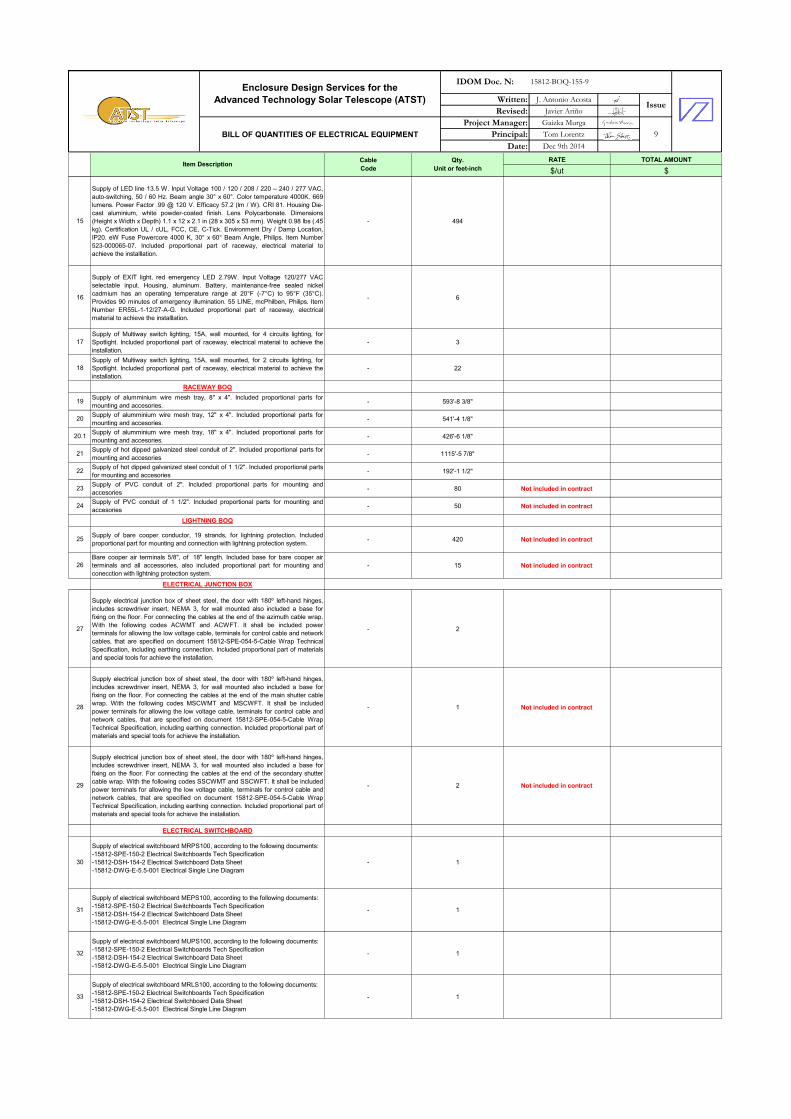
15
Supply of LED line 13.5 W. Input Voltage 100 / 120 / 208 / 220 – 240 / 277 VAC,
auto-switching, 50 / 60 Hz. Beam angle 30° x 60°. Color temperature 4000K. 669
lumens. Power Factor .99 @ 120 V. Efficacy 57.2 (lm / W). CRI 81. Housing Die-
cast aluminium, white powder-coated finish. Lens Polycarbonate. Dimensions
(Height x Width x Depth) 1.1 x 12 x 2.1 in (28 x 305 x 53 mm). Weight 0.98 lbs (.45
kg). Certification UL / cUL, FCC, CE, C-Tick. Environment Dry / Damp Location,
IP20. eW Fuse Powercore 4000 K, 30° x 60° Beam Angle, Philips. Item Number
523-000065-07. Included proportional part of raceway, electrical material to
achieve the installlation.
- 494
16
Supply of EXIT light, red emergency LED 2.79W. Input Voltage 120/277 VAC
selectable input. Housing, aluminum. Battery, maintenance-free sealed nickel
cadmium has an operating temperature range at 20°F (-7°C) to 95°F (35°C).
Provides 90 minutes of emergency illumination. 55 LINE, mcPhilben, Philips. Item
Number ER55L-1-12/27-A-G. Included proportional part of raceway, electrical
material to achieve the installlation.
- 6
17
Supply of Multiway switch lighting, 15A, wall mounted, for 4 circuits lighting, for
Spotlight. Included proportional part of raceway, electrical material to achieve the
installation.
- 3
18
Supply of Multiway switch lighting, 15A, wall mounted, for 2 circuits lighting, for
Spotlight. Included proportional part of raceway, electrical material to achieve the
installation.
- 22
RACEWAY BOQ
19Supply of alumminium wire mesh tray, 8" x 4". Included proportional parts for
mounting and accesories.- 593'-8 3/8"
20Supply of alumminium wire mesh tray, 12" x 4". Included proportional parts for
mounting and accesories.- 541'-4 1/8"
20.1Supply of alumminium wire mesh tray, 18" x 4". Included proportional parts for
mounting and accesories.- 426'-6 1/8"
21Supply of hot dipped galvanized steel conduit of 2". Included proportional parts for
mounting and accesories- 1115'-5 7/8"
22Supply of hot dipped galvanized steel conduit of 1 1/2". Included proportional parts
for mounting and accesories- 192'-1 1/2"
23Supply of PVC conduit of 2". Included proportional parts for mounting and
accesories- 80 Not included in contract
24Supply of PVC conduit of 1 1/2". Included proportional parts for mounting and
accesories- 50 Not included in contract
LIGHTNING BOQ
25Supply of bare cooper conductor, 19 strands, for lightning protection. Included
proportional part for mounting and connection with lightning protection system.- 420 Not included in contract
26
Bare cooper air terminals 5/8", of 18" length. Included base for bare cooper air
terminals and all accessories, also included proportional part for mounting and
conecction with lightning protection system.
- 15 Not included in contract
ELECTRICAL JUNCTION BOX
27
Supply electrical junction box of sheet steel, the door with 180º left-hand hinges,
includes screwdriver insert, NEMA 3, for wall mounted also included a base for
fixing on the floor. For connecting the cables at the end of the azimuth cable wrap.
With the following codes ACWMT and ACWFT. It shall be included power
terminals for allowing the low voltage cable, terminals for control cable and network
cables, that are specified on document 15812-SPE-054-5-Cable Wrap Technical
Specification, including earthing connection. Included proportional part of materials
and special tools for achieve the installation.
- 2
28
Supply electrical junction box of sheet steel, the door with 180º left-hand hinges,
includes screwdriver insert, NEMA 3, for wall mounted also included a base for
fixing on the floor. For connecting the cables at the end of the main shutter cable
wrap. With the following codes MSCWMT and MSCWFT. It shall be included
power terminals for allowing the low voltage cable, terminals for control cable and
network cables, that are specified on document 15812-SPE-054-5-Cable Wrap
Technical Specification, including earthing connection. Included proportional part of
materials and special tools for achieve the installation.
- 1 Not included in contract
29
Supply electrical junction box of sheet steel, the door with 180º left-hand hinges,
includes screwdriver insert, NEMA 3, for wall mounted also included a base for
fixing on the floor. For connecting the cables at the end of the secondary shutter
cable wrap. With the following codes SSCWMT and SSCWFT. It shall be included
power terminals for allowing the low voltage cable, terminals for control cable and
network cables, that are specified on document 15812-SPE-054-5-Cable Wrap
Technical Specification, including earthing connection. Included proportional part of
materials and special tools for achieve the installation.
- 2 Not included in contract
ELECTRICAL SWITCHBOARD
30
Supply of electrical switchboard MRPS100, according to the following documents:
-15812-SPE-150-2 Electrical Switchboards Tech Specification
-15812-DSH-154-2 Electrical Switchboard Data Sheet
-15812-DWG-E-5.5-001 Electrical Single Line Diagram
- 1
31
Supply of electrical switchboard MEPS100, according to the following documents:
-15812-SPE-150-2 Electrical Switchboards Tech Specification
-15812-DSH-154-2 Electrical Switchboard Data Sheet
-15812-DWG-E-5.5-001 Electrical Single Line Diagram
- 1
32
Supply of electrical switchboard MUPS100, according to the following documents:
-15812-SPE-150-2 Electrical Switchboards Tech Specification
-15812-DSH-154-2 Electrical Switchboard Data Sheet
-15812-DWG-E-5.5-001 Electrical Single Line Diagram
- 1
33
Supply of electrical switchboard MRLS100, according to the following documents:
-15812-SPE-150-2 Electrical Switchboards Tech Specification
-15812-DSH-154-2 Electrical Switchboard Data Sheet
-15812-DWG-E-5.5-001 Electrical Single Line Diagram
- 1

RATE TOTAL AMOUNT
$/ut $Item Description
Cable
Code
Qty.
Unit or feet-inch
Written: J. Antonio Acosta
Revised: Javier Ariño
Project Manager: Gaizka Murga
Principal: Tom Lorentz
Date: Dec 9th 2014
Enclosure Design Services for the
Advanced Technology Solar Telescope (ATST)
IDOM Doc. N: 15812-BOQ-155-9
Issue
BILL OF QUANTITIES OF ELECTRICAL EQUIPMENT 9
34
Supply of electrical switchboard MEEL100, according to the following documents:
-15812-SPE-150-2 Electrical Switchboards Tech Specification
-15812-DSH-154-2 Electrical Switchboard Data Sheet
-15812-DWG-E-5.5-001 Electrical Single Line Diagram
- 1
34.1
Supply of electrical switchboard MELU100, according to the following documents:
-15812-SPE-150-2 Electrical Switchboards Tech Specification
-15812-DSH-154-2 Electrical Switchboard Data Sheet
-15812-DWG-E-5.5-001 Electrical Single Line Diagram
- 1
34.1.1
Supply of electrical switchboard MEVG100, according to the following documents:
-15812-SPE-150-2 Electrical Switchboards Tech Specification
-15812-DSH-154-2 Electrical Switchboard Data Sheet
-15812-DWG-E-5.5-001 Electrical Single Line Diagram
- 1
34.2
Supply of electrical switchboard CABINET 401, according to the following
documents:
-15812-SPE-150-2 Electrical Switchboards Tech Specification
-15812-DSH-154-2 Electrical Switchboard Data Sheet
-15812-DWG-E-5.5-011 Electrical Single Line Diagram
- 1
34.3
Supply of electrical switchboard CABINET 402, according to the following
documents:
-15812-SPE-150-2 Electrical Switchboards Tech Specification
-15812-DSH-154-2 Electrical Switchboard Data Sheet
-15812-DWG-E-5.5-011 Electrical Single Line Diagram
- 1
34.4
Supply of electrical switchboard CABINET 403, according to the following
documents:
-15812-SPE-150-2 Electrical Switchboards Tech Specification
-15812-DSH-154-2 Electrical Switchboard Data Sheet
-15812-DWG-E-5.5-011 Electrical Single Line Diagram
- 1
34.5
Supply of electrical switchboard CABINET 404, according to the following
documents:
-15812-SPE-150-2 Electrical Switchboards Tech Specification
-15812-DSH-154-2 Electrical Switchboard Data Sheet
-15812-DWG-E-5.5-011 Electrical Single Line Diagram
- 1
34.6
Supply of electrical switchboard CABINET 501, according to the following
documents:
-15812-SPE-150-2 Electrical Switchboards Tech Specification
-15812-DSH-154-2 Electrical Switchboard Data Sheet
-15812-DWG-E-5.5-011 Electrical Single Line Diagram
- 1
34.7
Supply of electrical switchboard CABINET 502, according to the following
documents:
-15812-SPE-150-2 Electrical Switchboards Tech Specification
-15812-DSH-154-2 Electrical Switchboard Data Sheet
-15812-DWG-E-5.5-011 Electrical Single Line Diagram
- 1
34.8
Supply of electrical switchboard CABINET 505, according to the following
documents:
-15812-SPE-150-2 Electrical Switchboards Tech Specification
-15812-DSH-154-2 Electrical Switchboard Data Sheet
-15812-DWG-E-5.5-011 Electrical Single Line Diagram
- 1
34.9
Supply of electrical switchboard CABINET 506, according to the following
documents:
-15812-SPE-150-2 Electrical Switchboards Tech Specification
-15812-DSH-154-2 Electrical Switchboard Data Sheet
-15812-DWG-E-5.5-011 Electrical Single Line Diagram
- 1
34.10
Supply of electrical switchboard CABINET 601, according to the following
documents:
-15812-SPE-150-2 Electrical Switchboards Tech Specification
-15812-DSH-154-2 Electrical Switchboard Data Sheet
-15812-DWG-E-5.5-011 Electrical Single Line Diagram
- 1
34.11
Supply of electrical switchboard CABINET 602, according to the following
documents:
-15812-SPE-150-2 Electrical Switchboards Tech Specification
-15812-DSH-154-2 Electrical Switchboard Data Sheet
-15812-DWG-E-5.5-011 Electrical Single Line Diagram
- 1
34.12
Supply of electrical switchboard CABINET 603, according to the following
documents:
-15812-SPE-150-2 Electrical Switchboards Tech Specification
-15812-DSH-154-2 Electrical Switchboard Data Sheet
-15812-DWG-E-5.5-011 Electrical Single Line Diagram
- 1
34.13
Supply of electrical switchboard CABINET 604, according to the following
documents:
-15812-SPE-150-2 Electrical Switchboards Tech Specification
-15812-DSH-154-2 Electrical Switchboard Data Sheet
-15812-DWG-E-5.5-011 Electrical Single Line Diagram
- 1
ELECTRICAL DISTRIBUTION TRANSFORMERS
35
Supply of electrical distribution transformer TRDE100, according to the following
documents:
-15812-SPE-147-2 Distribution Transformers Tech Specification
-15812-DSH-151-2 Distribution Transformers Data Sheet
-15812-DWG-E-5.5-001 Electrical Single Line Diagram
- 1
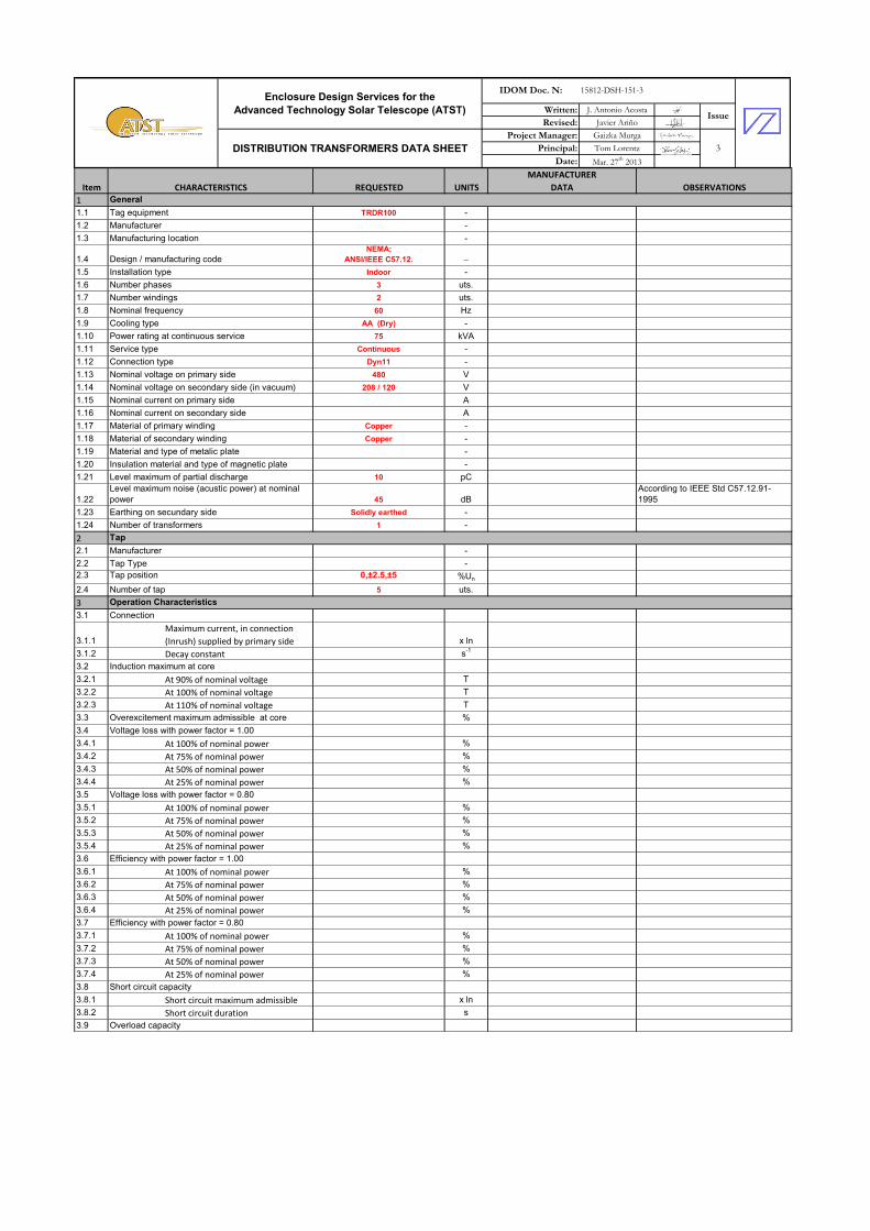
36
Supply of electrical distribution transformer TRDR100, according to the following
documents:
-15812-SPE-147-2 Distribution Transformers Tech Specification
-15812-DSH-151-2 Distribution Transformers Data Sheet
-15812-DWG-E-5.5-001 Electrical Single Line Diagram
- 1
37
Supply of electrical distribution transformer TRDU100, according to the following
documents:
-15812-SPE-147-2 Distribution Transformers Tech Specification
-15812-DSH-151-2 Distribution Transformers Data Sheet
-15812-DWG-E-5.5-001 Electrical Single Line Diagram
- 1
38
Supply of electrical distribution transformer TRDV100, according to the following
documents:
-15812-SPE-147-2 Distribution Transformers Tech Specification
-15812-DSH-151-2 Distribution Transformers Data Sheet
-15812-DWG-E-5.5-001 Electrical Single Line Diagram
- 1
Note: The quantities shown in this document are the expected ones, the contractor is responsible for verifying and providing the necessary materials and equipment to achieve a proper mechanical and electric installation.
RATE TOTAL AMOUNT
€/ut €
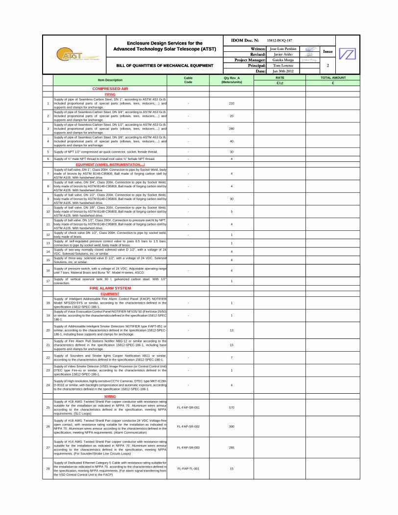
COMPRESSED AIRPIPING
1Supply of pipe of Seamless Carbon Steel, DN 1", according to ASTM A53 Gr.B.Included proportional parts of special parts (elbows, tees, reducers,…) andsupports and clamps for anchorage.
- 210
2Supply of pipe of Seamless Carbon Steel, DN 3/4", according to ASTM A53 Gr.B.Included proportional parts of special parts (elbows, tees, reducers,…) andsupports and clamps for anchorage.
- 20
3Supply of pipe of Seamless Carbon Steel, DN 1/2", according to ASTM A53 Gr.B.Included proportional parts of special parts (elbows, tees, reducers,…) andsupports and clamps for anchorage.
- 280
4Supply of pipe of Seamless Carbon Steel, DN 3/8", according to ASTM A53 Gr.B.Included proportional parts of special parts (elbows, tees, reducers,…) andsupports and clamps for anchorage.
- 40
5 Supply of NPT 1/2" compressed air quick connector, socket, female thread. - 30
6 Supply of ½” male NPT thread to install root valve ½” female NPT thread. - 4
EQUIPMENT (VAlVES, INSTRUMENTATION,…)
7Supply of ball valve, DN 1", Class 200#, Connection to pipe by Socket Weld, bodymade of bronze by ASTM B148-C95800, Ball made of forging carbon stell byASTM A105. With handwheel drive.
- 4
8Supply of ball valve, DN 3/4", Class 200#, Connection to pipe by Socket Weld,body made of bronze by ASTM B148-C95800, Ball made of forging carbon stell byASTM A105. With handwheel drive.
- 4
9Supply of ball valve, DN 1/2", Class 200#, Connection to pipe by Socket Weld,body made of bronze by ASTM B148-C95800, Ball made of forging carbon stell byASTM A105. With handwheel drive.
- 30
10Supply of ball valve, DN 3/8", Class 200#, Connection to pipe by Socket Weld,body made of bronze by ASTM B148-C95800, Ball made of forging carbon stell byASTM A105. With handwheel drive.
- 5
11Supply of ball valve, DN 1/2", Class 200#, Connection to pressure swicht by NPT,body made of bronze by ASTM B148-C95800, Ball made of forging carbon stell byASTM A105. With handwheel drive.
- 4
12Supply of check valve DN 1/2", Class 200#, Connection to pipe by socket weld,body made of brass.
- 1
13Supply of self-regulated pressure control valve to pass 6.5 bars to 1.5 bars,connection to pipe by socket weld, body made of brass.
1
14Supply of two-way normally closed solenoid valve D 1/2", with a voltage of 24VDC. Solenoid Solutions, inc; or similar.
4
15Supply of three-way solenoid valve D 1/2", with a voltage of 24 VDC. SolenoidSolutions, inc; or similar.
4
16Supply of pressure switch, with a voltage of 24 VDC. Adjustable operating rangeuntil 7 bars. Material Brass and Buna "N". Model H-series, ASCO.
- 4
Item DescriptionCableCode
Qty Rev_A(Meters/units)
Written: Jose Luis Periñán
Revised: Javier Ariño
Project Manager: Gaizka Murga
Principal: Tom Lorentz
Date: Jan 30th 2012
Enclosure Design Services for theAdvanced Technology Solar Telescope (ATST)
IDOM Doc. N: 15812-BOQ-187
Issue
BILL OF QUANTITIES OF MECHANICAL EQUIPMENT 2
17Supply of vertical reservoir tank 90 l, galvanized carbon steel. With 1/2"connection.
1
FIRE ALARM SYSTEMEQUIPMENT
18Supply of Inteligent Addressable Fire Alarm Control Panel (FACP) NOTIFIERModel NFS320-SYS or similar, according to the characteristics defined in thespecification 15812-SPEC-186-1.
- 1
19Supply of Voice Evacuation Control Panel NOTIFIER NFV25/ 50 (FireVoice 25/50)or similar, according to the characteristicsdefined in the specification 15812-SPEC-186-1.
- 1
20Supply of Addressable Inteligent Smoke Detectors NOTIFIER type FAPT-851 orsimilar, according to the characteristics defined in the specification 15812-SPEC-186-1, including base supports and clamps for anchorage.
- 13
21Supply of Fire Alarm Pull Stations Notifier NBG-12 or similar according to thecharacteristics defined in the specification 15812-SPEC-186-1, including basesupports and clamps for anchorage.
15
22Supply of Sounders and Strobe lights Cooper Notification XB11 or similar,according to the characteristics defined in the specification 15812-SPEC-186-1.
- 7
23Supply of Video Smoke Detector (VSD) Image Processor (or Central Control Unit)DTEC type Fire-vu or similar, according to the characteristics defined in thespecification 15812-SPEC-186-1.
- 1
24Supply of High resolution,highly sensitiveCCTV Cameras, DTEC type MKT-IC2M-D-001E or similar, with backlight compensation and automatic exposure,accordingto the characteristics defined in the specification 15812-SPEC-186-1.
- 4
WIRING
25
Supply of #18 AWG Twisted Shield Pair copper conductor with resistance ratingsuitable for the installation as indicated in NFPA 70. Aluminium wires armouraccording to the characteristics defined in the specification, meeting NFPArequirements. (SLC Loops)
FL-FAP-SR-001 570
26
Supply of #18 AWG Twisted Shield Pair copper conductor 24 VDC Voltage-freeopen contact, with resistance rating suitable for the installation as indicated inNFPA 70. Aluminium wires armour according to the characteristics defined in thespecification, meeting NFPA requirements. (Alarm Communication)
FL-FAP-SR-002 300
27
Supply of #14 AWG Twisted Shield Pair copper conductor with resistance ratingsuitable for the installation as indicated in NFPA 70. Aluminium wires armouraccording to the characteristics defined in the specification, meeting NFPArequirements. (For Sounder/Strobe Line Circuits Loops)
FL-FAP-SR-003 265
28
Supply of Dedicated Ethernet Category 5 Cable with resistance rating suitable forthe installationas indicated in NFPA 70. according to the characteristics defined inthe specification, meeting NFPA requirements. (For alarm signal transferring fromthe VSD Central Control Unit to the FACP)
FL-FAP-TL-001 15
Written: Jose Luis Periñán
Revised: Javier Ariño
Project Manager: Gaizka Murga
Principal: Tom Lorentz
Date: Jan 30th 2012
Enclosure Design Services for theAdvanced Technology Solar Telescope (ATST)
IDOM Doc. N: 15812-BOQ-187
Issue
BILL OF QUANTITIES OF MECHANICAL EQUIPMENT 2
Heather Marshall
Text Box
Not included in contract
Heather Marshall
Text Box
Not included in contract
Heather Marshall
Text Box
Not included in contract
Heather Marshall
Text Box
Not included in contract
Heather Marshall
Text Box
Not included in contract
Heather Marshall
Text Box
Not included in contract
Heather Marshall
Text Box
Not included in contract
Heather Marshall
Text Box
Not included in contract
Heather Marshall
Text Box
Not included in contract
Heather Marshall
Text Box
Not included in contract
Heather Marshall
Text Box
Not included in contract
Heather Marshall
Text Box
Not included in contract
Heather Marshall
Text Box
Not included in contract
Heather Marshall
Text Box
Not included in contract
Heather Marshall
Text Box
Not included in contract
Heather Marshall
Text Box
Not included in contract
Heather Marshall
Text Box
Not included in contract

29
Supply of #14 AWG Twisted Shield Pair copper conductor with extruded XLPEinsulationwith resistance rating suitable for the installationas indicated in NFPA 70and with LSF (low smoke and fume) sheath. Aluminium wires armour according tothe characteristics defined in the specification, meeting NFPA requirements. (Fordata transferring from cameras to the VSD Central Control Unit)
FL-FAP-TL-002 375
30Supply of PVC conduit of 1". Included proportional parts for mounting andaccesories
- 75
Item CHARACTERISTICS REQUESTED UNITS
MANUFACTURER
DATA OBSERVATIONS
1
1.1 Tag equipment TRDR100 -
1.2 Manufacturer -
1.3 Manufacturing location -
1.4 Design / manufacturing code
NEMA;
ANSI/IEEE C57.12. -
1.5 Installation type Indoor -
1.6 Number phases 3 uts.
1.7 Number windings 2 uts.
1.8 Nominal frequency 60 Hz
1.9 Cooling type AA (Dry) -
1.10 Power rating at continuous service 75 kVA
1.11 Service type Continuous -
1.12 Connection type Dyn11 -
1.13 Nominal voltage on primary side 480 V
1.14 Nominal voltage on secondary side (in vacuum) 208 / 120 V
1.15 Nominal current on primary side A
1.16 Nominal current on secondary side A
1.17 Material of primary winding Copper -
1.18 Material of secondary winding Copper -
1.19 Material and type of metalic plate -
1.20 Insulation material and type of magnetic plate -
1.21 Level maximum of partial discharge 10 pC
1.22
Level maximum noise (acustic power) at nominal
power 45 dB
According to IEEE Std C57.12.91-
1995
1.23 Earthing on secundary side Solidly earthed -
1.24 Number of transformers 1 -
2
2.1 Manufacturer -
2.2 Tap Type -
2.3 Tap position 0,±2.5,±5 %Un
2.4 Number of tap 5 uts.
3
3.1 Connection
3.1.1
Maximum current, in connection
(Inrush) supplied by primary side x ln
3.1.2 Decay constant s-1
3.2 Induction maximum at core
3.2.1 At 90% of nominal voltage T
3.2.2 At 100% of nominal voltage T
3.2.3 At 110% of nominal voltage T
3.3 Overexcitement maximum admissible at core %
3.4 Voltage loss with power factor = 1.00
3.4.1 At 100% of nominal power %
3.4.2 At 75% of nominal power %
3.4.3 At 50% of nominal power %
3.4.4 At 25% of nominal power %
3.5 Voltage loss with power factor = 0.80
3.5.1 At 100% of nominal power %
3.5.2 At 75% of nominal power %
3.5.3 At 50% of nominal power %
3.5.4 At 25% of nominal power %
3.6 Efficiency with power factor = 1.00
3.6.1 At 100% of nominal power %
3.6.2 At 75% of nominal power %
3.6.3 At 50% of nominal power %
3.6.4 At 25% of nominal power %
3.7 Efficiency with power factor = 0.80
3.7.1 At 100% of nominal power %
3.7.2 At 75% of nominal power %
3.7.3 At 50% of nominal power %
3.7.4 At 25% of nominal power %
3.8 Short circuit capacity
3.8.1 Short circuit maximum admissible x ln
3.8.2 Short circuit duration s
3.9 Overload capacity
General
Tap
Operation Characteristics
Written: J. Antonio Acosta
Revised: Javier Ariño
Project Manager: Gaizka Murga
Principal: Tom Lorentz
Date: Mar. 27th
2013
Enclosure Design Services for the
Advanced Technology Solar Telescope (ATST)
IDOM Doc. N: 15812-DSH-151-3
Issue
DISTRIBUTION TRANSFORMERS DATA SHEET 3
Heather Marshall
Text Box
According to ASHRAE 90.1
Heather Marshall
Text Box
According to ASHRAE 90.1

4
4.1 Material and type of insulation on primary side Impregnated - Optional: Epoxi resin encapsulated
4.2 Material and type of insulation on secondary side Impregnated - Optional: Epoxi resin encapsulated
4.3 Thermal class of insulation -
4.4 Maximum temperature of insulation ºC
4.5
Increase of temperature measered on windings at
ambient temperature, measured by resitance
variation 65 K
4.6 Insulation on primary side
4.6.1 Maximum voltage on material kV
4.6.2 Voltage test at industry frequency 3 kV
4.6.3 Voltage test at lightning impulse type kV
4.7 Insulation on secondary side
4.7.1 Maximum voltage on material kV
4.7.2 Voltage test at industry frequency 3 kV
4.7.3 Voltage test at lightning impulse type kV
5
5.1 Losses in vaccum
5.1.1 At 90% of nominal voltage W
5.1.2 At 100% of nominal voltage W
5.1.3 At 110% of nominal voltage W
5.2 Current in vaccum
5.2.1 At 90% of nominal voltage A
5.2.2 At 100% of nominal voltage A
5.2.3 At 110% of nominal voltage A
5.3 Losses due to load
5.3.1 Upper tap W
5.3.2 Central tap W
5.3.3 Bottom tap W
5.4
Short circuit direct impedance (referred to nominal
power)
5.4.1 Upper tap %
5.4.2 Central tap %
5.4.3 Bottom tap %
5.4.4 Tolerance %
5.4.5
Resistive component of short circuit
at central tap %
5.4.6
Inductive component of short circuit
at central tap %
5.5
Short circuit homopolar impedance (referred to
nominal power)
5.5.1 Upper tap %
5.5.2 Central tap %
5.5.3 Bottom tap %
5.5.4 Tolerance %
5.5.5
Resistive component of short circuit
at central tap %
5.5.6
Inductive component of short circuit
at central tap %
5.6 Losses due to cooling W
5.7 Total losses at nominal voltage and nominal power W
6
6.1 Total dimensions
6.1.1 Height inch
6.1.2 Width inch
6.1.3 Length inch
6.2 Transport dimensions
6.2.1 Height inch
6.2.2 Width inch
6.2.3 Length inch
7
7.1 Total weight
7.2 Weight to transport (piece heaviest)
7.3 Weight of core and windings
8
8.1 Connections on primary side
8.1.1 Type of connections
8.1.2 Number of cables and size
8.2 Connections on secondary side
8.2.1 Type of connections
8.2.2 Number of cables and size
Weight
Connections
NOTE: To compliment by supplier, for each type of cable tray.
Operation Characteristics
Losses
Dimensions
Item CHARACTERISTICS REQUESTED UNITS MANUFACTURER DATA OBSERVATIONS
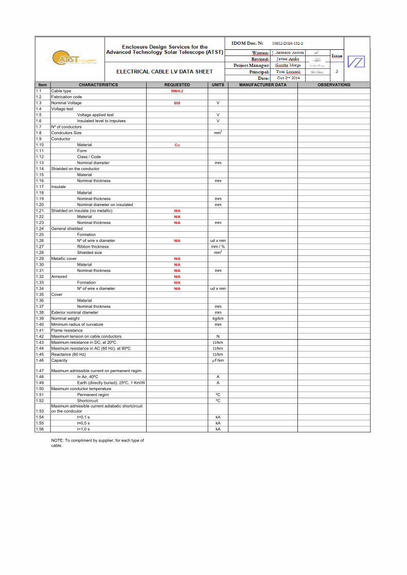
1.1 Cable type RWH-2
1.2 Fabrication code
1.3 Nominal Voltage 600 V
1.4 Voltage test
1.5 Voltage applied test V
1.6 Insulated level to impulses V
1.7 Nº of conductors
1.8 Condcutors Size mm2
1.9 Conductor
1.10 Material Cu
1.11 Form
1.12 Class / Code
1.13 Nominal diameter mm
1.14 Shielded on the conductor
1.15 Material
1.16 Nominal thickness mm
1.17 Insulate
1.18 Material
1.19 Nominal thickness mm
1.20 Nominal diameter on insulated mm
1.21 Shielded on insulate (no metallic) N/A
1.22 Material N/A
1.23 Nominal thickness N/A mm
1.24 General shielded
1.25 Formation
1.26 Nº of wire x diameter N/A ud x mm
1.27 Ribbon thickness mm / %
1.28 Shielded size mm2
1.29 Metallic cover N/A
1.30 Material N/A
1.31 Nominal thickness N/A mm
1.32 Armored N/A
1.33 Formation N/A
1.34 Nº of wire x diameter N/A ud x mm
1.35 Cover
1.36 Material
1.37 Nominal thickness mm
1.38 Exterior nominal diameter mm
1.39 Nominal weight kg/km
1.40 Minimum radius of curvature mm
1.41 Flame resistance
1.42 Maximum tension on cable conductors N
1.43 Maximum resistance in DC, at 20ºC W/km
1.44 Maximum resistance in AC (60 Hz), at 90ºC W/km
1.45 Reactance (60 Hz) W/km
1.46 Capacity mF/km
1.47 Maximum admissible current on permanent regim
1.48 In Air, 40ºC A
1.49 Earth (directly buried), 25ºC, 1 Km/W A
1.50 Maximum conductor temperature
1.51 Permanent regim ºC
1.52 Shortcircuit ºC
1.53
Maximum admissible current adiabatic shortcircuit
on the condcutor
1.54 t=0,1 s kA
1.55 t=0,5 s kA
1.56 t=1,0 s kA
NOTE: To compliment by supplier, for each type of
cable.
Item CHARACTERISTICS REQUESTED UNITS
MANUFACTURER
DATA OBSERVATIONS
1
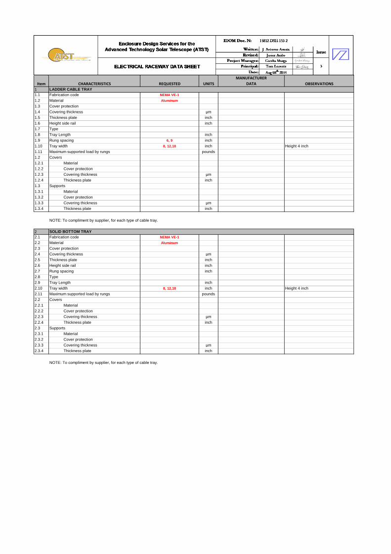
1.1 Fabrication code NEMA VE-1
1.2 Material Aluminum
1.3 Cover protection1.4 Covering thickness µm1.5 Thickness plate inch1.6 Height side rail inch1.7 Type1.8 Tray Length inch1.9 Rung spacing 6, 9 inch1.10 Tray width 8, 12,18 inch Height 4 inch1.11 Maximum supported load by rungs pounds1.2 Covers1.2.1 Material1.2.2 Cover protection1.2.3 Covering thickness µm1.2.4 Thickness plate inch1.3 Supports1.3.1 Material1.3.2 Cover protection1.3.3 Covering thickness µm1.3.4 Thickness plate inch
2
2.1 Fabrication code NEMA VE-1
2.2 Material Aluminum
2.3 Cover protection2.4 Covering thickness µm2.5 Thickness plate inch2.6 Height side rail inch2.7 Rung spacing inch2.8 Type2.9 Tray Length inch2.10 Tray width 8, 12,18 inch Height 4 inch2.11 Maximum supported load by rungs pounds2.2 Covers2.2.1 Material2.2.2 Cover protection2.2.3 Covering thickness µm2.2.4 Thickness plate inch2.3 Supports2.3.1 Material2.3.2 Cover protection2.3.3 Covering thickness µm2.3.4 Thickness plate inch
LADDER CABLE TRAY
NOTE: To compliment by supplier, for each type of cable tray.
SOLID BOTTOM TRAY
NOTE: To compliment by supplier, for each type of cable tray.

Item CHARACTERISTICS REQUESTED UNITS
MANUFACTURER
DATA OBSERVATIONS
3
3.1 Fabrication code NEMA VE-1
3.2 Material Aluminum
3.3 Cover protection3.4 Covering thickness µm3.5 Thickness plate inch3.6 Height side rail inch3.7 Rung spacing inch3.8 Type3.9 Tray Length inch3.10 Tray width 8, 12,18 inch Height 4 inch3.11 Maximum supported load by rungs pounds3.2 Covers3.2.1 Material3.2.2 Cover protection3.2.3 Covering thickness µm3.2.4 Thickness plate inch3.3 Supports3.3.1 Material3.3.2 Cover protection3.3.3 Covering thickness µm3.3.4 Thickness plate inch
4
4.1 Fabrication code ANSI C80.1
4.2 Material Hot dipped galvanized steel
4.3 Covering thickness4.3.1 Interior µm4.3.2 Exterior µm4.4 Length inch
4.5 Diameter 1/2,3/4,1,1 1/4,1 1/2,2 inch
4.6 Type of thread at the ends4.7 Circuit boxes4.7.1 Material4.7.2 Thickness plate inch
4.7.3 Cover protection4.7.4 Covering thickness µm4.7.5 Protection grade4.8 Accessories4.8.1 Model4.8.2 Material4.8.3 Thickness plate4.8.4 Cover protection4.8.5 Covering thickness4.8.6 Diameter
CONDUITS
NOTE: To compliment by supplier, for each type of conduit.
WIRE MESH TRAY
NOTE: To compliment by supplier, for each type of cable tray.
Item CHARACTERISTICS REQUESTED UNITS
MANUFACTURER
DATA OBSERVATIONS
1
1.1 Fabrication code
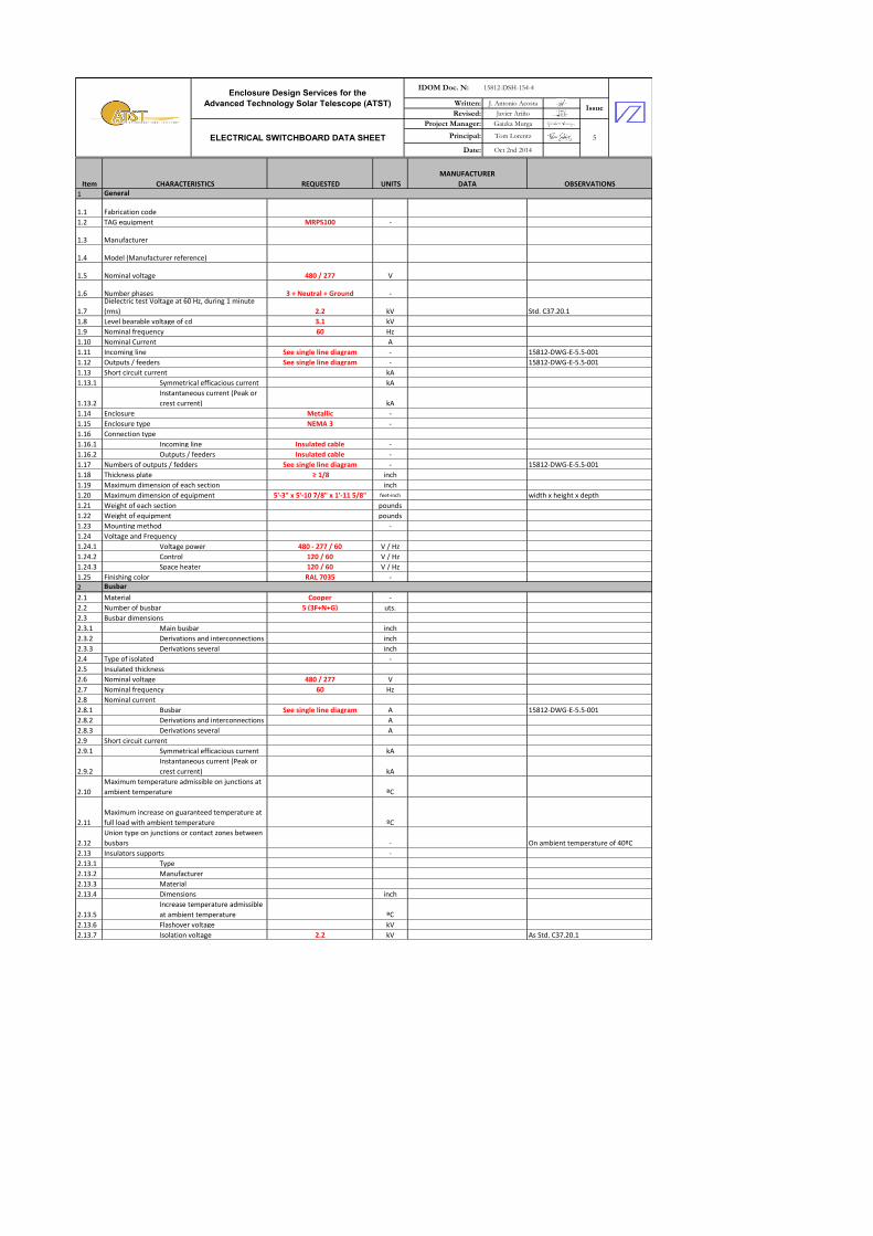
1.2 TAG equipment MRPS100 -
1.3 Manufacturer
1.4 Model (Manufacturer reference)
1.5 Nominal voltage 480 / 277 V
1.6 Number phases 3 + Neutral + Ground -
1.7
Dielectric test Voltage at 60 Hz, during 1 minute
(rms) 2.2 kV Std. C37.20.1
1.8 Level bearable voltage of cd 3.1 kV
1.9 Nominal frequency 60 Hz
1.10 Nominal Current A
1.11 Incoming line See single line diagram - 15812-DWG-E-5.5-001
1.12 Outputs / feeders See single line diagram - 15812-DWG-E-5.5-001
1.13 Short circuit current kA
1.13.1 Symmetrical efficacious current kA
1.13.2
Instantaneous current (Peak or
crest current) kA
1.14 Enclosure Metallic -
1.15 Enclosure type NEMA 3 -
1.16 Connection type
1.16.1 Incoming line Insulated cable -
1.16.2 Outputs / feeders Insulated cable -
1.17 Numbers of outputs / fedders See single line diagram - 15812-DWG-E-5.5-001
1.18 Thickness plate ≥ 1/8 inch
1.19 Maximum dimension of each section inch
1.20 Maximum dimension of equipment 5'-3" x 5'-10 7/8" x 1'-11 5/8" feet-inch width x height x depth
1.21 Weight of each section pounds
1.22 Weight of equipment pounds
1.23 Mounting method -
1.24 Voltage and Frequency
1.24.1 Voltage power 480 - 277 / 60 V / Hz
1.24.2 Control 120 / 60 V / Hz
1.24.3 Space heater 120 / 60 V / Hz
1.25 Finishing color RAL 7035 -
2
2.1 Material Cooper -
2.2 Number of busbar 5 (3F+N+G) uts.
2.3 Busbar dimensions
2.3.1 Main busbar inch
2.3.2 Derivations and interconnections inch
2.3.3 Derivations several inch
2.4 Type of isolated -
2.5 Insulated thickness
2.6 Nominal voltage 480 / 277 V
2.7 Nominal frequency 60 Hz
2.8 Nominal current
2.8.1 Busbar See single line diagram A 15812-DWG-E-5.5-001
2.8.2 Derivations and interconnections A
2.8.3 Derivations several A
2.9 Short circuit current
2.9.1 Symmetrical efficacious current kA
2.9.2
Instantaneous current (Peak or
crest current) kA
2.10
Maximum temperature admissible on junctions at
ambient temperature ºC
2.11
Maximum increase on guaranteed temperature at
full load with ambient temperature ºC
2.12
Union type on junctions or contact zones between
busbars - On ambient temperature of 40ºC
2.13 Insulators supports -
2.13.1 Type
2.13.2 Manufacturer
2.13.3 Material
2.13.4 Dimensions inch
2.13.5
Increase temperature admissible
at ambient temperature ºC
2.13.6 Flashover voltage kV
2.13.7 Isolation voltage 2.2 kV As Std. C37.20.1
Busbar
General
Written: J. Antonio Acosta
Revised: Javier Ariño
Project Manager: Gaizka Murga
Principal: Tom Lorentz
Date: Oct 2nd 2014
15812-DSH-154-4
Issue
ELECTRICAL SWITCHBOARD DATA SHEET 5
Enclosure Design Services for the
Advanced Technology Solar Telescope (ATST)
IDOM Doc. N:
Written: J. Antonio Acosta
Revised: Javier Ariño
Project Manager: Gaizka Murga
Principal: Tom Lorentz
Date: Oct 2nd 2014
15812-DSH-154-4
Issue
ELECTRICAL SWITCHBOARD DATA SHEET 5
Enclosure Design Services for the
Advanced Technology Solar Telescope (ATST)
IDOM Doc. N:
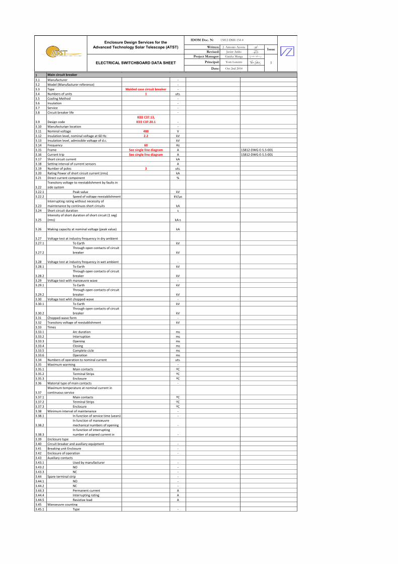
3
3.1 Manufacturer -
3.2 Model (Manufacturer reference) -
3.3 Type Molded case circuit breaker -
3.4 Numbers of units 1 uts.
3.5 Cooling Method -
3.6 Insulation -
3.7 Service -
3.8 Circuit breaker life -
3.9 Design code
IEEE C37.13,
IEEE C37.20.1 -
3.10 Manufacturign location -
3.11 Nominal voltage 480 V
3.12 Insulation level, nominal voltage at 60 Hz. 2.2 kV
3.13 Insulation level, admissible voltage of d.c. kV
3.14 Frequency 60 Hz
3.15 Frame See single line diagram A 15812-DWG-E-5.5-001
3.16 Current trip See single line diagram A 15812-DWG-E-5.5-001
3.17 Short circuit current kA
3.18 Setting interval of current sensors A
3.19 Number of poles 3 uts.
3.20 Rating Power of short circuit current (rms) kA
3.21 Direct current component %
3.22
Transitory voltage to reestablishment by faults in
side system
3.22.1 Peak value kV
3.22.2 Speed of voltage reestablishment kV/µs
3.23
Interrupting rating without necessity of
maintenance by continuos short circuits kA
3.24 Short circuit duration s
3.25
Intensity of short duration of short circuit (1 seg)
(rms) kA-s
3.26 Making capacity at nominal voltage (peak value) kA
3.27 Voltage test at industry frequency in dry ambient
3.27.1 To Earth kV
3.27.2
Through open contacts of circuit
breaker kV
3.28 Voltage test at industry frequency in wet ambient -
3.28.1 To Earth kV
3.28.2
Through open contacts of circuit
breaker kV
3.29 Voltage test with manoeuvre wave -
3.29.1 To Earth kV
3.29.2
Through open contacts of circuit
breaker kV
3.30 Voltage test whit chopped-wave -
3.30.1 To Earth kV
3.30.2
Through open contacts of circuit
breaker kV
3.31 Chopped-wave form -
3.32 Transitory voltage of reestablishment kV
3.33 Times
3.33.1 Arc duration ms
3.33.2 Interruption ms
3.33.3 Opening ms
3.33.4 Closing ms
3.33.5 Complete cicle ms
3.33.6 Operation ms
3.34 Numbers of operation to nominal current uts.
3.35 Maximum warming -
3.35.1 Main contacts ºC
3.35.2 Terminal Strips ºC
3.35.3 Enclosure ºC
3.36 Material type of main contacts -
3.37
Maximum temperature at nominal current in
continuous service
3.37.1 Main contacts ºC
3.37.2 Terminal Strips ºC
3.37.3 Enclosure ºC
3.38 Minimum interval of maintenance -
3.38.1 In function of service time (years) -
3.38.2
In function of manoeuvre
mechanical numbers of opening -
3.38.3
In function of interrupting
number of asigned current in -
3.39 Enclosure type
3.40 Circuit breaker and auxiliary equipment -
3.41 Breaking unit Enclosure -
3.42 Enclosure of operation -
3.43 Auxiliary contacts
3.43.1 Used by manufacturer -
3.43.2 NO -
3.43.3 NC -
3.44 Spare terminal strip -
3.44.1 NO -
3.44.2 NC -
3.44.3 Permanent current A
3.44.4 Interrupting rating A
3.44.5 Resistive load A
3.45 Manoeuvre counting
3.45.1 Type -
Main circuit breaker

Written: J. Antonio Acosta
Revised: Javier Ariño
Project Manager: Gaizka Murga
Principal: Tom Lorentz
Date: Oct 2nd 2014
15812-DSH-154-4
Issue
ELECTRICAL SWITCHBOARD DATA SHEET 5
Enclosure Design Services for the
Advanced Technology Solar Telescope (ATST)
IDOM Doc. N:
4 Circuit breakers output / fedder (For each one)
4.1 Manufacturer -
4.2 Model (Manufacturer reference) -
4.3 Type
Thermomagnetic (regulable
current) -
4.4 Numbers of units See single line diagram uts. 15812-DWG-E-5.5-001
4.5 Cooling Method -
4.6 Insulation -
4.7 Service -
4.8 Circuit breaker life -
4.9 Design code
IEEE C37.13,
IEEE C37.20.1 -
4.10 Manufacturign location -
4.11 Nominal voltage 480 V
4.12 Insulation level, nominal voltage at 60 Hz. 2.2 kV
4.13 Insulation level, admissible voltage of d.c. kV
4.14 Frequency 60 Hz
4.15 Frame See single line diagram A 15812-DWG-E-5.5-001
4.16 Current trip See single line diagram A 15812-DWG-E-5.5-001
4.17 Short circuit current kA
4.18 Setting interval of current sensors A
4.19 Number of poles See single line diagram uts. 15812-DWG-E-5.5-001
4.20 Rating Power of short circuit current (rms) kA
4.21 Direct current component %
4.22
Transitory voltage to reestablishment by faults in
side system
4.22.1 Peak value kV
4.22.2 Speed of voltage reestablishment kV/µs
4.23
Interrupting rating without necessity of
maintenance by continuos short circuits kA
4.24 Short circuit duration s
4.25
Intensity of short duration of short circuit (1 seg)
(rms) kA-s
4.26 Making capacity at nominal voltage (peak value) kA
4.27 Voltage test at industry frequency in dry ambient
4.27.1 To Earth kV
4.27.2
Through open contacts of circuit
breaker kV
4.28 Voltage test at industry frequency in wet ambient -
4.28.1 To Earth kV
4.28.2
Through open contacts of circuit
breaker kV
4.29 Voltage test with manoeuvre wave -
4.29.1 To Earth kV
4.29.2
Through open contacts of circuit
breaker kV
4.30 Voltage test whit chopped-wave -
4.30.1 To Earth kV
4.30.2
Through open contacts of circuit
breaker kV
4.31 Chopped-wave form -
4.32 Transitory voltage of reestablishment kV
4.33 Times
4.33.1 Arc duration ms
4.33.2 Interruption ms
4.33.3 Opening ms
4.33.4 Closing ms
4.33.5 Complete cicle ms
4.33.6 Operation ms
4.34 Numbers of operation to nominal current uts.
4.35 Maximum warming -
4.35.1 Main contacts ºC
4.35.2 Terminal Strips ºC
4.35.3 Enclosure ºC
4.36 Material type of main contacts -
4.37
Maximum temperature at nominal current in
continuous service
4.37.1 Main contacts ºC
4.37.2 Terminal Strips ºC
4.37.3 Enclosure ºC
4.38 Minimum interval of maintenance -
4.38.1 In function of service time (years) -
4.38.2
In function of manoeuvre
mechanical numbers of opening -
4.38.3
In function of interrupting
number of asigned current in -
4.39 Enclosure type
4.40 Circuit breaker and auxiliary equipment -
4.41 Breaking unit Enclosure -
4.42 Enclosure of operation -
4.43 Auxiliary contacts
4.43.1 Used by manufacturer -
4.43.2 NO -
4.43.3 NC -
4.44 Spare terminal strip -
4.44.1 NO -
4.44.2 NC -
4.44.3 Permanent current A
4.44.4 Interrupting rating A
4.44.5 Resistive load A
4.45 Manoeuvre counting
4.45.1 Type -
Written: J. Antonio Acosta
Revised: Javier Ariño
Project Manager: Gaizka Murga
Principal: Tom Lorentz
Date: Oct 2nd 2014
15812-DSH-154-4
Issue
ELECTRICAL SWITCHBOARD DATA SHEET 5
Enclosure Design Services for the
Advanced Technology Solar Telescope (ATST)
IDOM Doc. N:
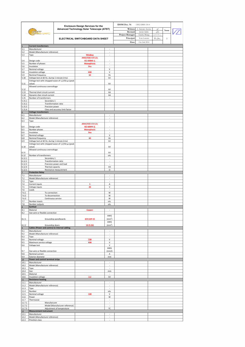
5
5.1 Manufacturer -
5.2 Model (Manufacturer reference) -
5.3 Type Window -
5.4 Design code
ANSI/IEEE C57,13;
IEC 60044-1; -
5.5 Number of phases Monophasic -
5.6 Insulation Dry -
5.7 Nominal voltage V
5.8 Insulation voltage 600 V
5.9 Nominal frequency 60 Hz
5.10 Voltage test at 60 Hz, during 1 minute (rms) kV
5.11
Voltage test whit chopped-wave of 1,2/50 µs (peak
value) kV
5.12
Allowed continuous overvoltage
kV
5.13 Thermal short circuit current kA
5.14 Dynamic shor circuit current kA
5.15 Number of transformers -
5.15.1 Secondary 1
5.15.2 Transformation ratio
5.15.3 Precision power
5.15.4 Class and accuracy limit factor
6
6.1 Manufacturer -
6.2 Model (Manufacturer reference) -
6.3 Type -
6.4 Design code
ANSI/IEEE C57,13;
IEC 60044-2; -
6.5 Number phases Monophasic -
6.6 Insulation Dry -
6.7 Nominal voltage V
6.8 Nominal frequency 60 Hz
6.9 Voltage test at 60 Hz, during 1 minute (rms) kV
6.10
Voltage test whit chopped-wave of 1,2/50 µs (peak
value) kV
6.11
Allowed continuous overvoltage
kV
6.12 Number of transformers uts.
6.12.1 Secondary 1 -
6.12.2 Transformation ratio -
6.12.3 Precision power and load -
6.12.4 Thermal capacity VA
6.12.5 Resistance measurement Ω
7
7.1 Manufacturer -
7.2 Model (Manufacturer reference) -
7.3 Type -
7.4 Current inputs 5 A
7.5 Voltage inputs 20 V
7.6 Loads -
7.6.1 To connection W
7.6.2 To disconnection W
7.6.3 Continuous service W
7.7 Number inputs uts.
7.8 Number outputs uts.
8
8.1 Material Copper -
8.2 Size wire or flexible connection
8.2.1 Grounding panelboards 4/0 (107.2)
AWG
(mm2)
8.2.2 Grounding doors 10 (5.26)
AWG
(mm2)
9
9.1 Manufacturer -
9.2 Model (Manufacturer reference) -
9.3 Type -
9.4 Nominal voltage 220 V
9.5 Maximum service voltage 600 V
9.6 Voltage test V
9.7 Size wire or flexible connection
AWG
(mm2)
9.8 Nominal current A
9.9 Exterior diameter mm
10
10.1 Manufacturer -
10.2 Model (Manufacturer reference) -
10.3 Type -
10.4 Size mm
10.5 Material -
10.6 Insulation voltage 2.2 kV
11
11.1 Manufacturer -
11.2 Model (Manufacturer reference) -
11.3 Type -
11.4 Number uts.
11.5 Nominal voltage 120 V
11.6 Power W
11.7 Thermostat -
11.7.1 Manufacturer -
11.7.2 Model (Manufacturer reference) -
11.7.3 Adjustment of temperature ºC
12
12.1 Manufacturer -
12.2 Model (Manufacturer reference) -
12.3 Presition class -
Current transformers
Voltage transformers
Protection Relay
Earthed
Cables (Power and contro) to internal cabling
Power and control terminal strips
Resistance heating
Measurement instrument

Written: J. Antonio Acosta
Revised: Javier Ariño
Project Manager: Gaizka Murga
Principal: Tom Lorentz
Date: Oct 2nd 2014
15812-DSH-154-4
Issue
ELECTRICAL SWITCHBOARD DATA SHEET 5
Enclosure Design Services for the
Advanced Technology Solar Telescope (ATST)
IDOM Doc. N:
13
13.1 Manufacturer -
13.2 Model (Manufacturer reference) -
13.3 Type -
13.4 Insulators
13.4.1 Type -
13.4.2 Nominal voltage kV
13.4.3 Insulation voltage kV
14
14.1 Incoming supply on top -
14.2 Outputs / feeders on top -
14.3 Control on top -
15
15.1 Manufacturer -
15.2 Model (Manufacturer reference) -
15.3 Type -
15.4 DC on voltage V
15
15.1 Material -
15.2 Dimensions inch
15.3 Material and type of screws -
15.4 Color -
15.5 Plate -
15.6 Type and dimensions letters -
The TRDR100 transformer is included in Switchboard MRPS100
Measurement voltage
Nameplate
NOTE: To fullfill by supplier
Connection
Signaling Led's
Item CHARACTERISTICS REQUESTED UNITS
MANUFACTURER
DATA OBSERVATIONS
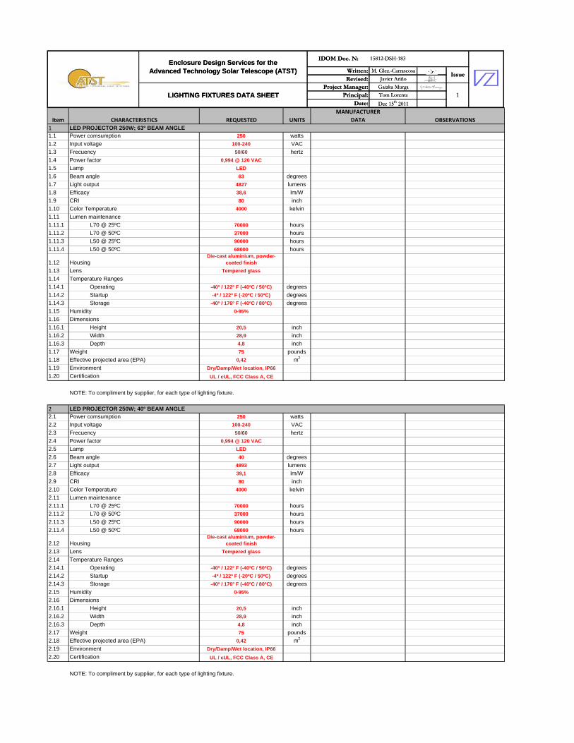
11.1 Power comsumption 250 watts
1.2 Input voltage 100-240 VAC
1.3 Frecuency 50/60 hertz
1.4 Power factor 0,994 @ 120 VAC
1.5 Lamp LED
1.6 Beam angle 63 degrees
1.7 Light output 4827 lumens
1.8 Efficacy 38,6 lm/W
1.9 CRI 80 inch
1.10 Color Temperature 4000 kelvin
1.11 Lumen maintenance
1.11.1 L70 @ 25ºC 70000 hours
1.11.2 L70 @ 50ºC 37000 hours
1.11.3 L50 @ 25ºC 90000 hours
1.11.4 L50 @ 50ºC 68000 hours
1.12 HousingDie-cast aluminium, powder-
coated finish
1.13 Lens Tempered glass
1.14 Temperature Ranges
1.14.1 Operating -40º / 122º F (-40ºC / 50ºC) degrees
1.14.2 Startup -4º / 122º F (-20ºC / 50ºC) degrees
1.14.3 Storage -40º / 176º F (-40ºC / 80ºC) degrees
1.15 Humidity 0-95%
1.16 Dimensions
1.16.1 Height 20,5 inch
1.16.2 Width 28,9 inch
1.16.3 Depth 4,8 inch
1.17 Weight 75 pounds
1.18 Effective projected area (EPA) 0,42 m2
1.19 Environment Dry/Damp/Wet location, IP66
1.20 Certification UL / cUL, FCC Class A, CE
LED PROJECTOR 250W; 63º BEAM ANGLE
NOTE: To compliment by supplier, for each type of lighting fixture.
Written: M. Glez.-Carrascosa
Revised: Javier Ariño
Project Manager: Gaizka Murga
Principal: Tom Lorentz
Date: Dec 15th 2011
Enclosure Design Services for theAdvanced Technology Solar Telescope (ATST)
IDOM Doc. N: 15812-DSH-183
Issue
LIGHTING FIXTURES DATA SHEET 1
22.1 Power comsumption 250 watts
2.2 Input voltage 100-240 VAC
2.3 Frecuency 50/60 hertz
2.4 Power factor 0,994 @ 120 VAC
2.5 Lamp LED
2.6 Beam angle 40 degrees
2.7 Light output 4893 lumens
2.8 Efficacy 39,1 lm/W
2.9 CRI 80 inch
2.10 Color Temperature 4000 kelvin
2.11 Lumen maintenance
2.11.1 L70 @ 25ºC 70000 hours
2.11.2 L70 @ 50ºC 37000 hours
2.11.3 L50 @ 25ºC 90000 hours
2.11.4 L50 @ 50ºC 68000 hours
2.12 HousingDie-cast aluminium, powder-
coated finish
2.13 Lens Tempered glass
2.14 Temperature Ranges
2.14.1 Operating -40º / 122º F (-40ºC / 50ºC) degrees
2.14.2 Startup -4º / 122º F (-20ºC / 50ºC) degrees
2.14.3 Storage -40º / 176º F (-40ºC / 80ºC) degrees
2.15 Humidity 0-95%
2.16 Dimensions
2.16.1 Height 20,5 inch
2.16.2 Width 28,9 inch
2.16.3 Depth 4,8 inch
2.17 Weight 75 pounds
2.18 Effective projected area (EPA) 0,42 m2
2.19 Environment Dry/Damp/Wet location, IP66
2.20 Certification UL / cUL, FCC Class A, CE
LED PROJECTOR 250W; 40º BEAM ANGLE
NOTE: To compliment by supplier, for each type of lighting fixture.
Written: M. Glez.-Carrascosa
Revised: Javier Ariño
Project Manager: Gaizka Murga
Principal: Tom Lorentz
Date: Dec 15th 2011
Enclosure Design Services for theAdvanced Technology Solar Telescope (ATST)
IDOM Doc. N: 15812-DSH-183
Issue
LIGHTING FIXTURES DATA SHEET 1

33.1 Power comsumption 250 watts
3.2 Input voltage 100-240 VAC
3.3 Frecuency 50/60 hertz
3.4 Power factor 0,994 @ 120 VAC
3.5 Lamp LED
3.6 Beam angle 23 degrees
3.7 Light output 4968 lumens
3.8 Efficacy 39,7 lm/W
3.9 CRI 80 inch
3.10 Color Temperature 4000 kelvin
3.11 Lumen maintenance
3.11.1 L70 @ 25ºC 70000 hours
3.11.2 L70 @ 50ºC 37000 hours
3.11.3 L50 @ 25ºC 90000 hours
3.11.4 L50 @ 50ºC 68000 hours
3.12 HousingDie-cast aluminium, powder-
coated finish
3.13 Lens Tempered glass
3.14 Temperature Ranges
3.14.1 Operating -40º / 122º F (-40ºC / 50ºC) degrees
3.14.2 Startup -4º / 122º F (-20ºC / 50ºC) degrees
3.14.3 Storage -40º / 176º F (-40ºC / 80ºC) degrees
3.15 Humidity 0-95%
3.16 Dimensions
3.16.1 Height 20,5 inch
3.16.2 Width 28,9 inch
3.16.3 Depth 4,8 inch
3.17 Weight 75 pounds
3.18 Effective projected area (EPA) 0,42 m2
3.19 Environment Dry/Damp/Wet location, IP66
3.20 Certification UL / cUL, FCC Class A, CE
44.1 Power comsumption 12,5 watts
4.2 Input voltage 100-277 VAC
4.3 Frecuency 50/60 hertz
4 4 P f t 0 99 @ 120 VAC
LED PROJECTOR 250W; 23º BEAM ANGLE
LED LINE 12.5W; 125ºX120º BEAM ANGLE
NOTE: To compliment by supplier, for each type of lighting fixture.
4.4 Power factor 0,99 @ 120 VAC
4.5 Lamp LED
4.6 Beam angle 125ºx120º degrees
4.7 Light output 632 lumens
4.8 Efficacy 53,1 lm/W
4.9 CRI 81 inch
4.10 Color Temperature 4000 kelvin
4.11 Lumen maintenance
4.11.1 L70 @ 25ºC 50000 hours
4.11.2 L70 @ 50ºC 37000 hours
4.11.3 L50 @ 25ºC 90000 hours
4.11.4 L50 @ 50ºC 80000 hours
4.12 HousingDie-cast aluminium, white powder-
coated finish
4.13 Lens Polycarbonate
4.14 Temperature Ranges
4.14.1 Operating -4º / 122º F (-20ºC / 50ºC) degrees
4.14.2 Startup -4º / 122º F (-20ºC / 50ºC) degrees
4.14.3 Storage -40º / 176º F (-40ºC / 80ºC) degrees
4.15 Humidity 0-95%
4.16 Dimensions
4.16.1 Height 1,64 inch
4.16.2 Width 12 inch
4.16.3 Depth 1,5 inch
4.17 Weight 0,82 pounds
4.18 Environment Dry/Damp location, IP20
4.19 Certification UL / cUL, FCC, CE, CCC
4.20 Accessories
4.20.1 Jumper cable UL/cUL 1 foots
4.20.2 Jumper cable UL/cUL 5 foots
4.20.3 Wiring compartment terminator UL/Cul
4.20.4 Leader cable with terminator & strain relief 10 foots
NOTE: To compliment by supplier, for each type of lighting fixture.
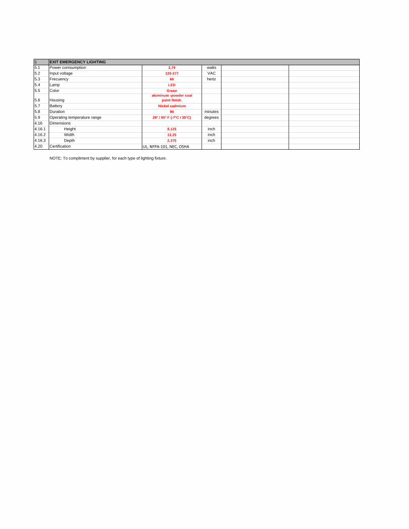
55.1 Power comsumption 2,79 watts
5.2 Input voltage 120-277 VAC
5.3 Frecuency 60 hertz
5.4 Lamp LED
5.5 Color Green
5.6 Housingaluminum -powder coat
paint finish.
5.7 Battery Nickel cadmium
5.8 Duration 90 minutes
5.9 Operating temperature range 20º / 95º F (-7ºC / 35ºC) degrees
4.16 Dimensions
4.16.1 Height 8,125 inch
4.16.2 Width 13,25 inch
4.16.3 Depth 2,375 inch
4.20 Certification UL, NFPA‐101, NEC, OSHA
EXIT EMERGENCY LIGHTING
NOTE: To compliment by supplier, for each type of lighting fixture.
RevisionKKS code
Description Voltage [V]Power [kW]
From ToCross-section
[AWG o kcmil]Lenght [ft] Notes
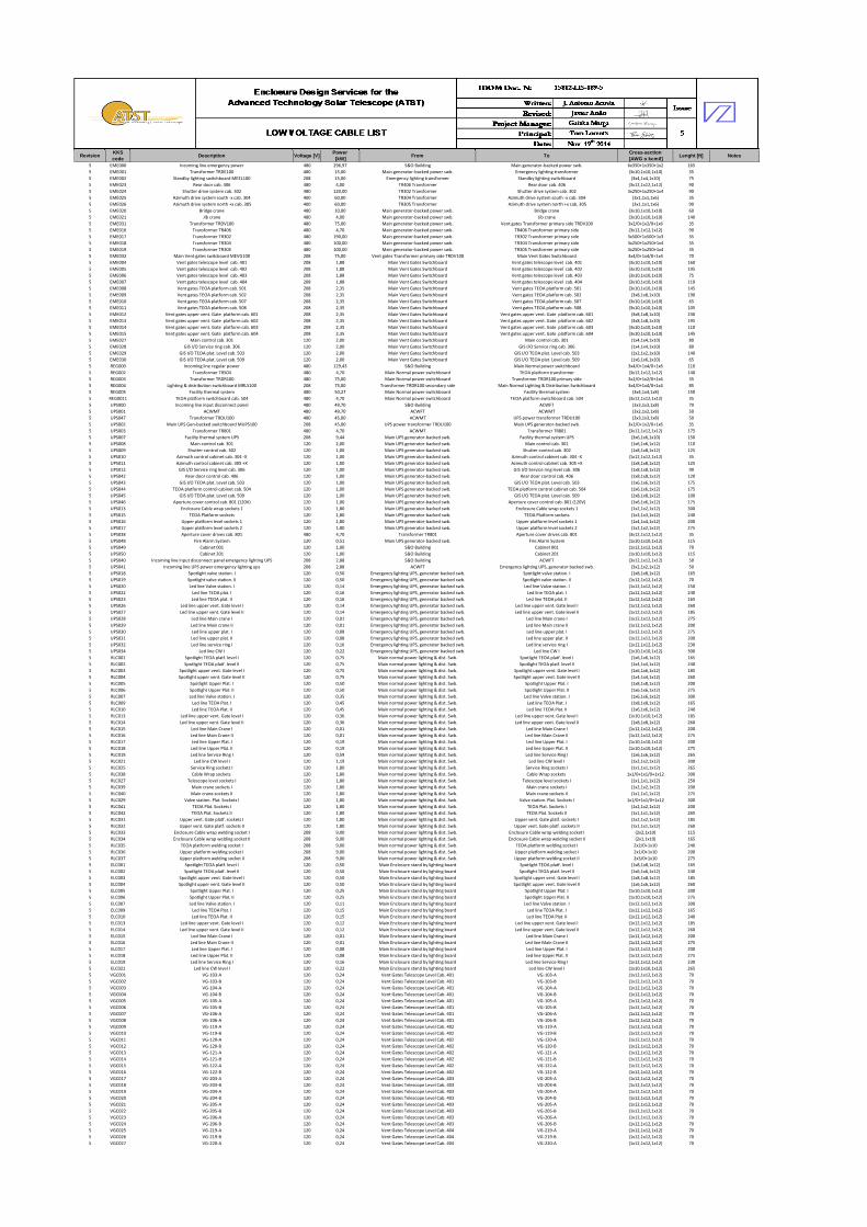
5 EME000 Incoming line emergency power 480 296,97 S&O Building Main generator-backed power swb. 6x350+1x350+1x2 165
5 EME001 Transformer TRDE100 480 15,00 Main generator-backed power swb. Emergency lighting transformer (3x10,1x10,1x10) 35
5 EME002 Standby lighting switchboard MEEL100 208 15,00 Emergency lighting transformer Standby lighting switchboard (3x4,1x4,1x10) 75
5 EME023 Rear door cab. 406 480 4,00 TR406 Transformer Rear door cab. 406 (3x12,1x12,1x12) 90
5 EME024 Shutter drive system cab. 302 480 120,00 TR302 Transformer Shutter drive system cab. 302 3x250+1x250+1x4 90
5 EME025 Azimuth drive system south -x cab. 304 400 60,00 TR304 Transformer Azimuth drive system south -x cab. 304 (3x1,1x1,1x6) 35
5 EME026 Azimuth drive system north +x cab. 305 400 60,00 TR305 Transformer Azimuth drive system north +x cab. 305 (3x1,1x1,1x6) 90
5 EME020 Bridge crane 480 10,00 Main generator-backed power swb. Bridge crane (3x10,1x10,1x10) 60
5 EME021 Jib crane 480 4,00 Main generator-backed power swb. Jib crane (3x10,1x10,1x10) 140
5 EME031 Transformer TRDV100 480 75,00 Main generator-backed power swb. Vent gates Transformer primary side TRDV100 3x2/0+1x2/0+1x6 35
5 EME016 Transformer TR406 480 4,70 Main generator-backed power swb. TR406 Transformer primary side (3x12,1x12,1x12) 90
5 EME017 Transformer TR302 480 190,00 Main generator-backed power swb. TR302 Transformer primary side 3x500+1x500+1x3 35
5 EME018 Transformer TR304 480 100,00 Main generator-backed power swb. TR304 Transformer primary side 3x250+1x250+1x4 35
5 EME019 Transformer TR305 480 100,00 Main generator-backed power swb. TR305 Transformer primary side 3x250+1x250+1x4 35
5 EME032 Main Vent gates switcboard MEVG100 208 75,00 Vent gates Transformer primary side TRDV100 Main Vent Gates Switchboard 3x4/0+1x4/0+1x4 70
5 EME004 Vent gates telescope level cab. 401 208 1,88 Main Vent Gates Switchboard Vent gates telescope level cab. 401 (3x10,1x10,1x10) 160
5 EME005 Vent gates telescope level cab. 402 208 1,88 Main Vent Gates Switchboard Vent gates telescope level cab. 402 (3x10,1x10,1x10) 195
5 EME006 Vent gates telescope level cab. 403 208 1,88 Main Vent Gates Switchboard Vent gates telescope level cab. 403 (3x10,1x10,1x10) 75
5 EME007 Vent gates telescope level cab. 404 208 1,88 Main Vent Gates Switchboard Vent gates telescope level cab. 404 (3x10,1x10,1x10) 110
5 EME008 Vent gates TEOA platform cab. 501 208 2,35 Main Vent Gates Switchboard Vent gates TEOA platform cab. 501 (3x10,1x10,1x10) 145
5 EME009 Vent gates TEOA platform cab. 502 208 2,35 Main Vent Gates Switchboard Vent gates TEOA platform cab. 502 (3x8,1x8,1x10) 190
5 EME010 Vent gates TEOA platform cab. 507 208 2,35 Main Vent Gates Switchboard Vent gates TEOA platform cab. 507 (3x10,1x10,1x10) 65
5 EME011 Vent gates TEOA platform cab. 508 208 2,35 Main Vent Gates Switchboard Vent gates TEOA platform cab. 508 (3x10,1x10,1x10) 105
5 EME012 Vent gates upper vent. Gate platform cab. 601 208 2,35 Main Vent Gates Switchboard Vent gates upper vent. Gate platform cab. 601 (3x8,1x8,1x10) 230
5 EME013 Vent gates upper vent. Gate platform cab. 602 208 2,35 Main Vent Gates Switchboard Vent gates upper vent. Gate platform cab. 602 (3x8,1x8,1x10) 195
5 EME014 Vent gates upper vent. Gate platform cab. 603 208 2,35 Main Vent Gates Switchboard Vent gates upper vent. Gate platform cab. 603 (3x10,1x10,1x10) 110
5 EME015 Vent gates upper vent. Gate platform cab. 604 208 2,35 Main Vent Gates Switchboard Vent gates upper vent. Gate platform cab. 604 (3x10,1x10,1x10) 145
5 EME027 Main control cab. 301 120 2,00 Main Vent Gates Switchboard Main control cab. 301 (1x4,1x4,1x10) 80
5 EME028 GIS I/O Service ring cab. 306 120 2,00 Main Vent Gates Switchboard GIS I/O Service ring cab. 306 (1x4,1x4,1x10) 80
5 EME029 GIS I/O TEOA plat. Level cab. 503 120 2,00 Main Vent Gates Switchboard GIS I/O TEOA plat. Level cab. 503 (1x2,1x2,1x10) 140
5 EME030 GIS I/O TEOA plat. Level cab. 509 120 2,00 Main Vent Gates Switchboard GIS I/O TEOA plat. Level cab. 509 (1x6,1x6,1x10) 65
5 REG000 Incoming line regular power 480 129,43 S&O Building Main Normal power switchboard 3x4/0+1x4/0+1x6 110
5 REG002 Transformer TR504 480 4,70 Main Normal power switchboard TEOA platform transformer (3x12,1x12,1x12) 140
5 REG003 Transformer TRDR100 480 75,00 Main Normal power switchboard Transformer TRDR100 primary side 3x2/0+1x2/0+1x6 35
5 REG004 Lighting & distribution switchboard MRLS100 208 75,00 Transformer TRDR100 secondary side Main Normal Lighting & Distribution Switchboard 3x4/0+1x4/0+1x4 85
5 REG005 Facility thermal system 480 50,27 Main Normal power switchboard Facility thermal system (3x4,1x4,1x8) 150
5 REG0011 TEOA platform switchboard cab. 504 480 4,70 Main Normal power switchboard TEOA platform switchboard cab. 504 (3x12,1x12,1x12) 35
5 UPS000 Incoming line input disconnect panel 480 49,70 S&O Building ACWFT (3x3,1x3,1x8) 70
5 UPS001 ACWMT 480 49,70 ACWFT ACWMT (3x2,1x2,1x8) 50
5 UPS047 Transformer TRDU100 480 45,00 ACWMT UPS power transformer TRDU100 (3x3,1x3,1x8) 50
5 UPS002 Main UPS Gen-backed switchboard MUPS100 208 45,00 UPS power transformer TRDU100 Main UPS generator-backed swb. 3x2/0+1x2/0+1x6 35
5 UPS003 Transformer TR801 480 4,70 ACWMT Transformer TR801 (3x12,1x12,1x12) 175
5 UPS007 Facility thermal system UPS 208 9,44 Main UPS generator-backed swb. Facility thermal system UPS (3x6,1x6,1x10) 150
5 UPS008 Main control cab. 301 120 2,00 Main UPS generator-backed swb. Main control cab. 301 (1x6,1x6,1x12) 110
5 UPS009 Shutter control cab. 302 120 1,00 Main UPS generator-backed swb. Shutter control cab. 302 (1x8,1x8,1x12) 125
5 UPS010 Azimuth control cabinet cab. 304 -X 120 1,00 Main UPS generator-backed swb. Azimuth control cabinet cab. 304 -X (1x12,1x12,1x12) 35
5 UPS011 Azimuth control cabinet cab. 305 +X 120 1,00 Main UPS generator-backed swb. Azimuth control cabinet cab. 305 +X (1x8,1x8,1x12) 125
5 UPS012 GIS I/O Service ring level cab. 306 120 1,00 Main UPS generator-backed swb. GIS I/O Service ring level cab. 306 (1x8,1x8,1x12) 90
5 UPS042 Rear door control cab. 406 120 1,00 Main UPS generator-backed swb. Rear door control cab. 406 (1x8,1x8,1x12) 120
5 UPS043 GIS I/O TEOA plat. Level cab. 503 120 1,00 Main UPS generator-backed swb. GIS I/O TEOA plat. Level cab. 503 (1x6,1x6,1x12) 175
5 UPS044 TEOA platform control cabinet cab. 504 120 1,00 Main UPS generator-backed swb. TEOA platform control cabinet cab. 504 (1x6,1x6,1x12) 175
5 UPS045 GIS I/O TEOA plat. Level cab. 509 120 1,00 Main UPS generator-backed swb. GIS I/O TEOA plat. Level cab. 509 (1x8,1x8,1x12) 100
5 UPS046 Aperture cover control cab. 801 (120V) 120 1,00 Main UPS generator-backed swb. Aperture cover control cab. 801 (120V) (1x6,1x6,1x12) 175
5 UPS013 Enclosure Cable wrap sockets 1 120 1,80 Main UPS generator-backed swb. Enclosure Cable wrap sockets 1 (1x2,1x2,1x12) 300
5 UPS015 TEOA Platform sockets 120 1,80 Main UPS generator-backed swb. TEOA Platform sockets (1x3,1x3,1x12) 240
5 UPS016 Upper platform level sockets 1 120 1,80 Main UPS generator-backed swb. Upper platform level sockets 1 (1x4,1x4,1x12) 200
5 UPS017 Upper platform level sockets 2 120 1,80 Main UPS generator-backed swb. Upper platform level sockets 2 (1x2,1x2,1x12) 275
5 UPS038 Aperture cover drives cab. 801 480 4,70 Transformer TR801 Aperture cover drives cab. 801 (3x12,1x12,1x12) 35
5 UPS048 Fire Alarm System 120 0,51 Main UPS generator-backed swb. Fire Alarm System (1x10,1x10,1x12) 115
5 UPS049 Cabinet 001 120 1,00 S&O Building Cabinet 001 (1x12,1x12,1x12) 70
5 UPS050 Cabinet 201 120 1,00 S&O Building Cabinet 201 (1x10,1x10,1x12) 115
5 UPS040 Incoming line input disconnect panel emergency lighting UPS 208 2,88 S&O Building ACWFT (3x12,1x12,1x12) 50
5 UPS041 Incoming line UPS power emergency lighting ups 208 2,88 ACWFT Emergency lighting UPS, generator backed swb. (3x2,1x2,1x12) 50
5 UPS018 Spotlight valve station. I 120 0,50 Emergency lighting UPS, generator backed swb. Spotlight valve station. I (1x8,1x8,1x12) 165
5 UPS019 Spotlight valve station. II 120 0,50 Emergency lighting UPS, generator backed swb. Spotlight valve station. II (1x12,1x12,1x12) 70
5 UPS020 Led line Valve station. I 120 0,14 Emergency lighting UPS, generator backed swb. Led line Valve station. I (1x12,1x12,1x12) 250
5 UPS022 Led line TEOA plat. I 120 0,16 Emergency lighting UPS, generator backed swb. Led line TEOA plat. I (1x12,1x12,1x12) 240
5 UPS023 Led line TEOA plat. II 120 0,16 Emergency lighting UPS, generator backed swb. Led line TEOA plat. II (1x12,1x12,1x12) 165
5 UPS026 Led line upper vent. Gate level I 120 0,14 Emergency lighting UPS, generator backed swb. Led line upper vent. Gate level I (1x12,1x12,1x12) 260
5 UPS027 Led line upper vent. Gate level II 120 0,14 Emergency lighting UPS, generator backed swb. Led line upper vent. Gate level II (1x12,1x12,1x12) 185
5 UPS028 Led line Main crane I 120 0,01 Emergency lighting UPS, generator backed swb. Led line Main crane I (1x12,1x12,1x12) 275
5 UPS029 Led line Main crane II 120 0,01 Emergency lighting UPS, generator backed swb. Led line Main crane II (1x12,1x12,1x12) 200
5 UPS030 Led line upper plat. I 120 0,08 Emergency lighting UPS, generator backed swb. Led line upper plat. I (1x12,1x12,1x12) 275
5 UPS031 Led line upper plat. II 120 0,08 Emergency lighting UPS, generator backed swb. Led line upper plat. II (1x12,1x12,1x12) 200
5 UPS032 Led line service ring I 120 0,16 Emergency lighting UPS, generator backed swb. Led line service ring I (1x12,1x12,1x12) 230
5 UPS034 Led line CW I 120 0,22 Emergency lighting UPS, generator backed swb. Led line CW I (1x10,1x10,1x12) 300
5 RLC001 Spotlight TEOA platf. level I 120 0,75 Main normal power lighting & dist. Swb. Spotlight TEOA platf. level I (1x6,1x6,1x12) 165
5 RLC002 Spotlight TEOA platf. level II 120 0,75 Main normal power lighting & dist. Swb. Spotlight TEOA platf. level II (1x4,1x4,1x12) 240
5 RLC003 Spotlight upper vent. Gate level I 120 0,75 Main normal power lighting & dist. Swb. Spotlight upper vent. Gate level I (1x6,1x6,1x12) 185
5 RLC004 Spotlight upper vent. Gate level II 120 0,75 Main normal power lighting & dist. Swb. Spotlight upper vent. Gate level II (1x4,1x4,1x12) 260
5 RLC005 Spotlight Upper Plat. I 120 0,50 Main normal power lighting & dist. Swb. Spotlight Upper Plat. I (1x8,1x8,1x12) 200
5 RLC006 Spotlight Upper Plat. II 120 0,50 Main normal power lighting & dist. Swb. Spotlight Upper Plat. II (1x6,1x6,1x12) 275
5 RLC007 Led line Valve station. I 120 0,35 Main normal power lighting & dist. Swb. Led line Valve station. I (1x6,1x6,1x12) 300
5 RLC009 Led line TEOA Plat. I 120 0,45 Main normal power lighting & dist. Swb. Led line TEOA Plat. I (1x8,1x8,1x12) 165
5 RLC010 Led line TEOA Plat. II 120 0,45 Main normal power lighting & dist. Swb. Led line TEOA Plat. II (1x6,1x6,1x12) 240
5 RLC013 Led line upper vent. Gate level I 120 0,36 Main normal power lighting & dist. Swb. Led line upper vent. Gate level I (1x10,1x10,1x12) 185
5 RLC014 Led line upper vent. Gate level II 120 0,36 Main normal power lighting & dist. Swb. Led line upper vent. Gate level II (1x8,1x8,1x12) 260
5 RLC015 Led line Main Crane I 120 0,01 Main normal power lighting & dist. Swb. Led line Main Crane I (1x12,1x12,1x12) 200
5 RLC016 Led line Main Crane II 120 0,01 Main normal power lighting & dist. Swb. Led line Main Crane II (1x12,1x12,1x12) 275
5 RLC017 Led line Upper Plat. I 120 0,19 Main normal power lighting & dist. Swb. Led line Upper Plat. I (1x10,1x10,1x12) 200
5 RLC018 Led line Upper Plat. II 120 0,19 Main normal power lighting & dist. Swb. Led line Upper Plat. II (1x10,1x10,1x12) 275
5 RLC019 Led line Service Ring I 120 0,59 Main normal power lighting & dist. Swb. Led line Service Ring I (1x6,1x6,1x12) 265
5 RLC021 Led line CW level I 120 1,19 Main normal power lighting & dist. Swb. Led line CW level I (1x2,1x2,1x12) 300
5 RLC025 Service Ring sockets I 120 1,80 Main normal power lighting & dist. Swb. Service Ring sockets I (1x1,1x1,1x12) 265
5 RLC038 Cable Wrap sockets 120 1,80 Main normal power lighting & dist. Swb. Cable Wrap sockets 1x1/0+1x1/0+1x12 300
5 RLC027 Telescope level sockets I 120 1,80 Main normal power lighting & dist. Swb. Telescope level sockets I (1x1,1x1,1x12) 250
5 RLC039 Main crane sockets I 120 1,80 Main normal power lighting & dist. Swb. Main crane sockets I (1x2,1x2,1x12) 200
5 RLC040 Main crane sockets II 120 1,80 Main normal power lighting & dist. Swb. Main crane sockets II (1x1,1x1,1x12) 275
5 RLC029 Valve station. Plat. Sockets I 120 1,80 Main normal power lighting & dist. Swb. Valve station. Plat. Sockets I 1x1/0+1x1/0+1x12 300
5 RLC041 TEOA Plat. Sockets I 120 1,80 Main normal power lighting & dist. Swb. TEOA Plat. Sockets I (1x2,1x2,1x12) 200
5 RLC042 TEOA Plat. Sockets II 120 1,80 Main normal power lighting & dist. Swb. TEOA Plat. Sockets II (1x1,1x1,1x12) 265
5 RLC031 Upper vent. Gate platf. sockets I 120 1,80 Main normal power lighting & dist. Swb. Upper vent. Gate platf. sockets I (1x2,1x2,1x12) 185
5 RLC032 Upper vent. Gate platf. sockets II 120 1,80 Main normal power lighting & dist. Swb. Upper vent. Gate platf. sockets II (1x1,1x1,1x12) 260
5 RLC033 Enclosure Cable wrap welding socket I 208 9,00 Main normal power lighting & dist. Swb. Enclosure Cable wrap welding socket I (2x2,1x10) 115
5 RLC034 Enclosure Cable wrap welding socket II 208 9,00 Main normal power lighting & dist. Swb. Enclosure Cable wrap welding socket II (2x1,1x10) 165
5 RLC035 TEOA platform welding socket I 208 9,00 Main normal power lighting & dist. Swb. TEOA platform welding socket I 2x2/0+1x10 240
5 RLC036 Upper platform welding socket I 208 9,00 Main normal power lighting & dist. Swb. Upper platform welding socket I 2x1/0+1x10 200
5 RLC037 Upper platform welding socket II 208 9,00 Main normal power lighting & dist. Swb. Upper platform welding socket II 2x3/0+1x10 275
5 ELC001 Spotlight TEOA platf. level I 120 0,50 Main Enclosure stand by lighting board Spotlight TEOA platf. level I (1x8,1x8,1x12) 165
5 ELC002 Spotlight TEOA platf. level II 120 0,50 Main Enclosure stand by lighting board Spotlight TEOA platf. level II (1x6,1x6,1x12) 240
5 ELC003 Spotlight upper vent. Gate level I 120 0,50 Main Enclosure stand by lighting board Spotlight upper vent. Gate level I (1x8,1x8,1x12) 185
5 ELC004 Spotlight upper vent. Gate level II 120 0,50 Main Enclosure stand by lighting board Spotlight upper vent. Gate level II (1x6,1x6,1x12) 260
5 ELC005 Spotlight Upper Plat. I 120 0,25 Main Enclosure stand by lighting board Spotlight Upper Plat. I (1x10,1x10,1x12) 200
5 ELC006 Spotlight Upper Plat. II 120 0,25 Main Enclosure stand by lighting board Spotlight Upper Plat. II (1x10,1x10,1x12) 275
5 ELC007 Led line Valve station. I 120 0,11 Main Enclosure stand by lighting board Led line Valve station. I (1x12,1x12,1x12) 300
5 ELC009 Led line TEOA Plat. I 120 0,15 Main Enclosure stand by lighting board Led line TEOA Plat. I (1x12,1x12,1x12) 165
5 ELC010 Led line TEOA Plat. II 120 0,15 Main Enclosure stand by lighting board Led line TEOA Plat. II (1x12,1x12,1x12) 240
5 ELC013 Led line upper vent. Gate level I 120 0,12 Main Enclosure stand by lighting board Led line upper vent. Gate level I (1x12,1x12,1x12) 185
5 ELC014 Led line upper vent. Gate level II 120 0,12 Main Enclosure stand by lighting board Led line upper vent. Gate level II (1x12,1x12,1x12) 260
5 ELC015 Led line Main Crane I 120 0,01 Main Enclosure stand by lighting board Led line Main Crane I (1x12,1x12,1x12) 200
5 ELC016 Led line Main Crane II 120 0,01 Main Enclosure stand by lighting board Led line Main Crane II (1x12,1x12,1x12) 275
5 ELC017 Led line Upper Plat. I 120 0,08 Main Enclosure stand by lighting board Led line Upper Plat. I (1x12,1x12,1x12) 200
5 ELC018 Led line Upper Plat. II 120 0,08 Main Enclosure stand by lighting board Led line Upper Plat. II (1x12,1x12,1x12) 275
5 ELC019 Led line Service Ring I 120 0,16 Main Enclosure stand by lighting board Led line Service Ring I (1x12,1x12,1x12) 230
5 ELC021 Led line CW level I 120 0,22 Main Enclosure stand by lighting board Led line CW level I (1x10,1x10,1x12) 265
5 VGC001 VG-103-A 120 0,24 Vent Gates Telescope Level Cab. 401 VG-103-A (1x12,1x12,1x12) 70
5 VGC002 VG-103-B 120 0,24 Vent Gates Telescope Level Cab. 401 VG-103-B (1x12,1x12,1x12) 70
5 VGC003 VG-104-A 120 0,24 Vent Gates Telescope Level Cab. 401 VG-104-A (1x12,1x12,1x12) 70
5 VGC004 VG-104-B 120 0,24 Vent Gates Telescope Level Cab. 401 VG-104-B (1x12,1x12,1x12) 70
5 VGC005 VG-105-A 120 0,24 Vent Gates Telescope Level Cab. 401 VG-105-A (1x12,1x12,1x12) 70
5 VGC006 VG-105-B 120 0,24 Vent Gates Telescope Level Cab. 401 VG-105-B (1x12,1x12,1x12) 70
5 VGC007 VG-106-A 120 0,24 Vent Gates Telescope Level Cab. 401 VG-106-A (1x12,1x12,1x12) 70
5 VGC008 VG-106-A 120 0,24 Vent Gates Telescope Level Cab. 401 VG-106-B (1x12,1x12,1x12) 70
5 VGC009 VG-119-A 120 0,24 Vent Gates Telescope Level Cab. 402 VG-119-A (1x12,1x12,1x12) 70
5 VGC010 VG-119-B 120 0,24 Vent Gates Telescope Level Cab. 402 VG-119-B (1x12,1x12,1x12) 70
5 VGC011 VG-120-A 120 0,24 Vent Gates Telescope Level Cab. 402 VG-120-A (1x12,1x12,1x12) 70
5 VGC012 VG-120-B 120 0,24 Vent Gates Telescope Level Cab. 402 VG-120-B (1x12,1x12,1x12) 70
5 VGC013 VG-121-A 120 0,24 Vent Gates Telescope Level Cab. 402 VG-121-A (1x12,1x12,1x12) 70
5 VGC014 VG-121-B 120 0,24 Vent Gates Telescope Level Cab. 402 VG-121-B (1x12,1x12,1x12) 70
5 VGC015 VG-122-A 120 0,24 Vent Gates Telescope Level Cab. 402 VG-122-A (1x12,1x12,1x12) 70
5 VGC016 VG-122-B 120 0,24 Vent Gates Telescope Level Cab. 402 VG-122-B (1x12,1x12,1x12) 70
5 VGC017 VG-203-A 120 0,24 Vent Gates Telescope Level Cab. 403 VG-203-A (1x12,1x12,1x12) 70
5 VGC018 VG-203-B 120 0,24 Vent Gates Telescope Level Cab. 403 VG-203-B (1x12,1x12,1x12) 70
5 VGC019 VG-204-A 120 0,24 Vent Gates Telescope Level Cab. 403 VG-204-A (1x12,1x12,1x12) 70
5 VGC020 VG-204-B 120 0,24 Vent Gates Telescope Level Cab. 403 VG-204-B (1x12,1x12,1x12) 70
5 VGC021 VG-205-A 120 0,24 Vent Gates Telescope Level Cab. 403 VG-205-A (1x12,1x12,1x12) 70
5 VGC022 VG-205-B 120 0,24 Vent Gates Telescope Level Cab. 403 VG-205-B (1x12,1x12,1x12) 70
5 VGC023 VG-206-A 120 0,24 Vent Gates Telescope Level Cab. 403 VG-206-A (1x12,1x12,1x12) 70
5 VGC024 VG-206-B 120 0,24 Vent Gates Telescope Level Cab. 403 VG-206-B (1x12,1x12,1x12) 70
5 VGC025 VG-219-A 120 0,24 Vent Gates Telescope Level Cab. 404 VG-219-A (1x12,1x12,1x12) 70
5 VGC026 VG-219-B 120 0,24 Vent Gates Telescope Level Cab. 404 VG-219-B (1x12,1x12,1x12) 70
5 VGC027 VG-220-A 120 0,24 Vent Gates Telescope Level Cab. 404 VG-220-A (1x12,1x12,1x12) 70
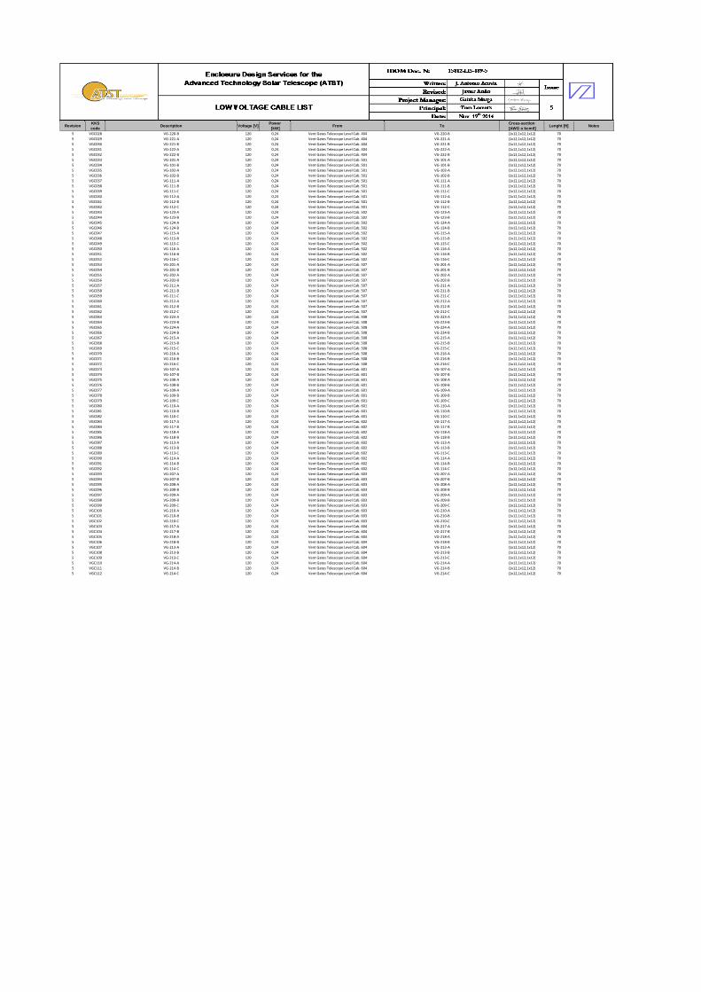
RevisionKKS code
Description Voltage [V]Power [kW]
From ToCross-section
[AWG o kcmil]Lenght [ft] Notes
5 VGC028 VG-220-B 120 0,24 Vent Gates Telescope Level Cab. 404 VG-220-B (1x12,1x12,1x12) 70
5 VGC029 VG-221-A 120 0,24 Vent Gates Telescope Level Cab. 404 VG-221-A (1x12,1x12,1x12) 70
5 VGC030 VG-221-B 120 0,24 Vent Gates Telescope Level Cab. 404 VG-221-B (1x12,1x12,1x12) 70
5 VGC031 VG-222-A 120 0,24 Vent Gates Telescope Level Cab. 404 VG-222-A (1x12,1x12,1x12) 70
5 VGC032 VG-222-B 120 0,24 Vent Gates Telescope Level Cab. 404 VG-222-B (1x12,1x12,1x12) 70
5 VGC033 VG-101-A 120 0,24 Vent Gates Telescope Level Cab. 501 VG-101-A (1x12,1x12,1x12) 70
5 VGC034 VG-101-B 120 0,24 Vent Gates Telescope Level Cab. 501 VG-101-B (1x12,1x12,1x12) 70
5 VGC035 VG-102-A 120 0,24 Vent Gates Telescope Level Cab. 501 VG-102-A (1x12,1x12,1x12) 70
5 VGC036 VG-102-B 120 0,24 Vent Gates Telescope Level Cab. 501 VG-102-B (1x12,1x12,1x12) 70
5 VGC037 VG-111-A 120 0,24 Vent Gates Telescope Level Cab. 501 VG-111-A (1x12,1x12,1x12) 70
5 VGC038 VG-111-B 120 0,24 Vent Gates Telescope Level Cab. 501 VG-111-B (1x12,1x12,1x12) 70
5 VGC039 VG-111-C 120 0,24 Vent Gates Telescope Level Cab. 501 VG-111-C (1x12,1x12,1x12) 70
5 VGC040 VG-112-A 120 0,24 Vent Gates Telescope Level Cab. 501 VG-112-A (1x12,1x12,1x12) 70
5 VGC041 VG-112-B 120 0,24 Vent Gates Telescope Level Cab. 501 VG-112-B (1x12,1x12,1x12) 70
5 VGC042 VG-112-C 120 0,24 Vent Gates Telescope Level Cab. 501 VG-112-C (1x12,1x12,1x12) 70
5 VGC043 VG-123-A 120 0,24 Vent Gates Telescope Level Cab. 502 VG-123-A (1x12,1x12,1x12) 70
5 VGC044 VG-123-B 120 0,24 Vent Gates Telescope Level Cab. 502 VG-123-B (1x12,1x12,1x12) 70
5 VGC045 VG-124-A 120 0,24 Vent Gates Telescope Level Cab. 502 VG-124-A (1x12,1x12,1x12) 70
5 VGC046 VG-124-B 120 0,24 Vent Gates Telescope Level Cab. 502 VG-124-B (1x12,1x12,1x12) 70
5 VGC047 VG-115-A 120 0,24 Vent Gates Telescope Level Cab. 502 VG-115-A (1x12,1x12,1x12) 70
5 VGC048 VG-115-B 120 0,24 Vent Gates Telescope Level Cab. 502 VG-115-B (1x12,1x12,1x12) 70
5 VGC049 VG-115-C 120 0,24 Vent Gates Telescope Level Cab. 502 VG-115-C (1x12,1x12,1x12) 70
5 VGC050 VG-116-A 120 0,24 Vent Gates Telescope Level Cab. 502 VG-116-A (1x12,1x12,1x12) 70
5 VGC051 VG-116-B 120 0,24 Vent Gates Telescope Level Cab. 502 VG-116-B (1x12,1x12,1x12) 70
5 VGC052 VG-116-C 120 0,24 Vent Gates Telescope Level Cab. 502 VG-116-C (1x12,1x12,1x12) 70
5 VGC053 VG-201-A 120 0,24 Vent Gates Telescope Level Cab. 507 VG-201-A (1x12,1x12,1x12) 70
5 VGC054 VG-201-B 120 0,24 Vent Gates Telescope Level Cab. 507 VG-201-B (1x12,1x12,1x12) 70
5 VGC055 VG-202-A 120 0,24 Vent Gates Telescope Level Cab. 507 VG-202-A (1x12,1x12,1x12) 70
5 VGC056 VG-202-B 120 0,24 Vent Gates Telescope Level Cab. 507 VG-202-B (1x12,1x12,1x12) 70
5 VGC057 VG-211-A 120 0,24 Vent Gates Telescope Level Cab. 507 VG-211-A (1x12,1x12,1x12) 70
5 VGC058 VG-211-B 120 0,24 Vent Gates Telescope Level Cab. 507 VG-211-B (1x12,1x12,1x12) 70
5 VGC059 VG-211-C 120 0,24 Vent Gates Telescope Level Cab. 507 VG-211-C (1x12,1x12,1x12) 70
5 VGC060 VG-212-A 120 0,24 Vent Gates Telescope Level Cab. 507 VG-212-A (1x12,1x12,1x12) 70
5 VGC061 VG-212-B 120 0,24 Vent Gates Telescope Level Cab. 507 VG-212-B (1x12,1x12,1x12) 70
5 VGC062 VG-212-C 120 0,24 Vent Gates Telescope Level Cab. 507 VG-212-C (1x12,1x12,1x12) 70
5 VGC063 VG-223-A 120 0,24 Vent Gates Telescope Level Cab. 508 VG-223-A (1x12,1x12,1x12) 70
5 VGC064 VG-223-B 120 0,24 Vent Gates Telescope Level Cab. 508 VG-223-B (1x12,1x12,1x12) 70
5 VGC065 VG-224-A 120 0,24 Vent Gates Telescope Level Cab. 508 VG-224-A (1x12,1x12,1x12) 70
5 VGC066 VG-224-B 120 0,24 Vent Gates Telescope Level Cab. 508 VG-224-B (1x12,1x12,1x12) 70
5 VGC067 VG-215-A 120 0,24 Vent Gates Telescope Level Cab. 508 VG-215-A (1x12,1x12,1x12) 70
5 VGC068 VG-215-B 120 0,24 Vent Gates Telescope Level Cab. 508 VG-215-B (1x12,1x12,1x12) 70
5 VGC069 VG-215-C 120 0,24 Vent Gates Telescope Level Cab. 508 VG-215-C (1x12,1x12,1x12) 70
5 VGC070 VG-216-A 120 0,24 Vent Gates Telescope Level Cab. 508 VG-216-A (1x12,1x12,1x12) 70
5 VGC071 VG-216-B 120 0,24 Vent Gates Telescope Level Cab. 508 VG-216-B (1x12,1x12,1x12) 70
5 VGC072 VG-216-C 120 0,24 Vent Gates Telescope Level Cab. 508 VG-216-C (1x12,1x12,1x12) 70
5 VGC073 VG-107-A 120 0,24 Vent Gates Telescope Level Cab. 601 VG-107-A (1x12,1x12,1x12) 70
5 VGC074 VG-107-B 120 0,24 Vent Gates Telescope Level Cab. 601 VG-107-B (1x12,1x12,1x12) 70
5 VGC075 VG-108-A 120 0,24 Vent Gates Telescope Level Cab. 601 VG-108-A (1x12,1x12,1x12) 70
5 VGC076 VG-108-B 120 0,24 Vent Gates Telescope Level Cab. 601 VG-108-B (1x12,1x12,1x12) 70
5 VGC077 VG-109-A 120 0,24 Vent Gates Telescope Level Cab. 601 VG-109-A (1x12,1x12,1x12) 70
5 VGC078 VG-109-B 120 0,24 Vent Gates Telescope Level Cab. 601 VG-109-B (1x12,1x12,1x12) 70
5 VGC079 VG-109-C 120 0,24 Vent Gates Telescope Level Cab. 601 VG-109-C (1x12,1x12,1x12) 70
5 VGC080 VG-110-A 120 0,24 Vent Gates Telescope Level Cab. 601 VG-110-A (1x12,1x12,1x12) 70
5 VGC081 VG-110-B 120 0,24 Vent Gates Telescope Level Cab. 601 VG-110-B (1x12,1x12,1x12) 70
5 VGC082 VG-110-C 120 0,24 Vent Gates Telescope Level Cab. 601 VG-110-C (1x12,1x12,1x12) 70
5 VGC083 VG-117-A 120 0,24 Vent Gates Telescope Level Cab. 602 VG-117-A (1x12,1x12,1x12) 70
5 VGC084 VG-117-B 120 0,24 Vent Gates Telescope Level Cab. 602 VG-117-B (1x12,1x12,1x12) 70
5 VGC085 VG-118-A 120 0,24 Vent Gates Telescope Level Cab. 602 VG-118-A (1x12,1x12,1x12) 70
5 VGC086 VG-118-B 120 0,24 Vent Gates Telescope Level Cab. 602 VG-118-B (1x12,1x12,1x12) 70
5 VGC087 VG-113-A 120 0,24 Vent Gates Telescope Level Cab. 602 VG-113-A (1x12,1x12,1x12) 70
5 VGC088 VG-113-B 120 0,24 Vent Gates Telescope Level Cab. 602 VG-113-B (1x12,1x12,1x12) 70
5 VGC089 VG-113-C 120 0,24 Vent Gates Telescope Level Cab. 602 VG-113-C (1x12,1x12,1x12) 70
5 VGC090 VG-114-A 120 0,24 Vent Gates Telescope Level Cab. 602 VG-114-A (1x12,1x12,1x12) 70
5 VGC091 VG-114-B 120 0,24 Vent Gates Telescope Level Cab. 602 VG-114-B (1x12,1x12,1x12) 70
5 VGC092 VG-114-C 120 0,24 Vent Gates Telescope Level Cab. 602 VG-114-C (1x12,1x12,1x12) 70
5 VGC093 VG-207-A 120 0,24 Vent Gates Telescope Level Cab. 603 VG-207-A (1x12,1x12,1x12) 70
5 VGC094 VG-207-B 120 0,24 Vent Gates Telescope Level Cab. 603 VG-207-B (1x12,1x12,1x12) 70
5 VGC095 VG-208-A 120 0,24 Vent Gates Telescope Level Cab. 603 VG-208-A (1x12,1x12,1x12) 70
5 VGC096 VG-208-B 120 0,24 Vent Gates Telescope Level Cab. 603 VG-208-B (1x12,1x12,1x12) 70
5 VGC097 VG-209-A 120 0,24 Vent Gates Telescope Level Cab. 603 VG-209-A (1x12,1x12,1x12) 70
5 VGC098 VG-209-B 120 0,24 Vent Gates Telescope Level Cab. 603 VG-209-B (1x12,1x12,1x12) 70
5 VGC099 VG-209-C 120 0,24 Vent Gates Telescope Level Cab. 603 VG-209-C (1x12,1x12,1x12) 70
5 VGC100 VG-210-A 120 0,24 Vent Gates Telescope Level Cab. 603 VG-210-A (1x12,1x12,1x12) 70
5 VGC101 VG-210-B 120 0,24 Vent Gates Telescope Level Cab. 603 VG-210-B (1x12,1x12,1x12) 70
5 VGC102 VG-210-C 120 0,24 Vent Gates Telescope Level Cab. 603 VG-210-C (1x12,1x12,1x12) 70
5 VGC103 VG-217-A 120 0,24 Vent Gates Telescope Level Cab. 604 VG-217-A (1x12,1x12,1x12) 70
5 VGC104 VG-217-B 120 0,24 Vent Gates Telescope Level Cab. 604 VG-217-B (1x12,1x12,1x12) 70
5 VGC105 VG-218-A 120 0,24 Vent Gates Telescope Level Cab. 604 VG-218-A (1x12,1x12,1x12) 70
5 VGC106 VG-218-B 120 0,24 Vent Gates Telescope Level Cab. 604 VG-218-B (1x12,1x12,1x12) 70
5 VGC107 VG-213-A 120 0,24 Vent Gates Telescope Level Cab. 604 VG-213-A (1x12,1x12,1x12) 70
5 VGC108 VG-213-B 120 0,24 Vent Gates Telescope Level Cab. 604 VG-213-B (1x12,1x12,1x12) 70
5 VGC109 VG-213-C 120 0,24 Vent Gates Telescope Level Cab. 604 VG-213-C (1x12,1x12,1x12) 70
5 VGC110 VG-214-A 120 0,24 Vent Gates Telescope Level Cab. 604 VG-214-A (1x12,1x12,1x12) 70
5 VGC111 VG-214-B 120 0,24 Vent Gates Telescope Level Cab. 604 VG-214-B (1x12,1x12,1x12) 70
5 VGC112 VG-214-C 120 0,24 Vent Gates Telescope Level Cab. 604 VG-214-C (1x12,1x12,1x12) 70
Enclosure Design Services for the Advanced Technology Solar Telescope (ATST)
DISTRIBUTION TRANSFORMERS TECHNICAL SPECIFICATION
IDOM Doc. N.: 15812-SPE-147 Issue: 5 Date: Oct. 2nd 2014
Contract No: C22019N
Name Signature Date
Written José Antonio Acosta
Oct. 2nd 2014
Revised Javier Ariño
Oct. 2nd 2014
Project Manager Gaizka Murga
Oct. 2nd 2014
Principal Tom Lorentz
Oct. 2nd 2014
File: 15812-SPE-147-5 Distribution Transformers Tech Specification.docx Pages: 20
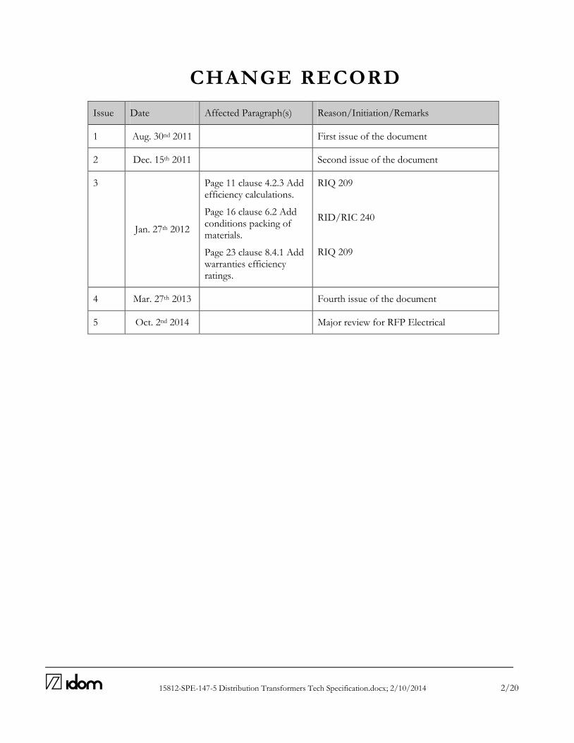
15812-SPE-147-5 Distribution Transformers Tech Specification.docx; 2/10/2014 2/20
CHANGE RECORD
Issue Date Affected Paragraph(s) Reason/Initiation/Remarks
1 Aug. 30nd 2011 First issue of the document
2 Dec. 15th 2011 Second issue of the document
3
Jan. 27th 2012
Page 11 clause 4.2.3 Add efficiency calculations.
Page 16 clause 6.2 Add conditions packing of materials.
Page 23 clause 8.4.1 Add warranties efficiency ratings.
RIQ 209
RID/RIC 240
RIQ 209
4 Mar. 27th 2013 Fourth issue of the document
5 Oct. 2nd 2014 Major review for RFP Electrical

15812-SPE-147-5 Distribution Transformers Tech Specification.docx; 2/10/2014 3/20
ABBREVIATIONS AD Applicable Document ATST Advanced Technology Solar Telescope AURA Association of Universities for Research in Astronomy CO Contract Officer COTR Contract Officer Technical Representative EMC Electromagnetic Compatibility F-ATP Factory Acceptance Tests Plan FEM Finite Element Model FOV Field of View GIS Global Interlock System ICD Interface Configuration Document I/F Interface LAN Local Area Network LIC Local Interlock Controller MIP Mandatory Inspection Points N/A Not Applicable NC Not Compliant PDR Preliminary Design Review PHA Preliminary Hazards Analysis QA Quality Assurance RAMS Reliability, Availability, Maintainability and Safety RD Reference Document RFP Request for Proposal S-ATP Safety Acceptance Tests Plan SOW Statement of Work S&O Support and Operations TBD To Be Defined TBC To Be Confirmed UPS Uninterrupted Power System WBS Work Breakdown Structure WP Work Package WPD Work Package Description
15812-SPE-147-5 Distribution Transformers Tech Specification.docx; 2/10/2014 4/20
TABLE OF CONTENTS
1 SCOPE OF THE DOCUMENT ................................................................................................. 6
2 ASSUMPTIONS CONSIDERED ............................................................................................... 7
3 GENERAL ................................................................................................................................... 8
4 SUPPLY SCOPE .......................................................................................................................... 9
4.1 EQUIPMENT ..................................................................................................................................................... 9
4.2 FACTORY TESTING ...................................................................................................................................... 9
4.3 ON SITE INSPECTIONS.............................................................................................................................. 11
4.4 TRANSPORT .................................................................................................................................................... 11
4.5 TRAINING COURSES .................................................................................................................................. 11
4.6 REPLACEMENT PARTS .............................................................................................................................. 11
4.7 SPARE PARTS .................................................................................................................................................. 12
4.8 DRAWINGS AND DOCUMENTATION ................................................................................................ 12
5 ENVIRONMENTAL CONDITIONS ON SITE ...................................................................... 13
6 PACKING AND PROTECTION DURING TRANSPORT AND STORAGE .......................... 14
6.1 MARKING ........................................................................................................................................................ 14
6.2 PACKING CONDITIONS OF EQUIPMENT ........................................................................................ 14
7 CODES AND STANDARDS ...................................................................................................... 15
7.1 GENERAL ........................................................................................................................................................ 15
7.2 OTHERS ............................................................................................................................................................ 15
7.3 REGULATION AND LEGISLATION ..................................................................................................... 15
8 TECHNICAL CHARACTERISTICS ........................................................................................ 16
8.1 SERVICE CONDITIONS ............................................................................................................................. 16
8.2 BASICS CHARACTERISTICS ..................................................................................................................... 16
8.3 GENERAL PREREQUISITE ....................................................................................................................... 17
8.4 WARRANTIES AND TOLERANCES ....................................................................................................... 20

15812-SPE-147-5 Distribution Transformers Tech Specification.docx; 2/10/2014 5/20

15812-SPE-147-5 Distribution Transformers Tech Specification.docx; 2/10/2014 6/20
1 S C OP E OF TH E D OC U M E N T
This specification defines the electrical distribution transformers for the ATST (Advanced Technology Solar Telescope) Project, Haleakala National Park, Hawaii.

15812-SPE-147-5 Distribution Transformers Tech Specification.docx; 2/10/2014 7/20
2 AS S U M P TI ONS C ONS I D ER E D
No significant assumption has been made in the last period.
15812-SPE-147-5 Distribution Transformers Tech Specification.docx; 2/10/2014 8/20
3 G E NE R AL
The supplier shall provide and install equipment in accordance with these specifications. The supplier shall provide any data required. Any changes to this specification shall be authorized by the owner in writing in advance. Approval of another drawing, design criteria, or specification shall not be construed to imply compliance with this document. The supplier shall perform each analysis, test procedure, inspection, and additional activity, as required to assure that the installation is in accordance with codes and industry standard practices, and is delivered in a complete and fully operable condition. This document covers design engineering, fabrication, inspection, quality control, factory testing, shipping, startup, and on-site testing. It also includes training for ATST personnel and parts replacement for three (3) years after completion of startup.

15812-SPE-147-5 Distribution Transformers Tech Specification.docx; 2/10/2014 9/20
4
4 S U P P LY S C OP E
The supplier shall adhere to the following requirements for the electrical distribution transformers.
4.1 EQUIPMENT
Equipment shall be constructed in accordance with this section, Section 8, and the drawings. This project’s transformers are:
Designation Description Power
TRDE100 Emergency Lighting Transformer 15 kVA
TRDR100 Regular Lighting Transformer 45 kVA
TRDU100 Main UPS Transformer lighting 75 kVA
Transformers shall be dry-type, varnish-impregnated, 480:208/120V, 60 Hz, delta-wye connection, with a tapping range on the primary side at ±2.5% and ±5%, ventilated for self-cooling, and rated for indoor installation and continuous service. Transformers shall be manufactured and tested in accordance with applicable IEEE standards. The supplier shall provide all tools necessary for maintenance, including tools to insert and withdraw integral breakers, if any. In addition, any necessary replacement parts during the first three years of operation shall be provided.
4.1.1 SCOPE OF SUPPLY
The scope of supply shall include the terminal lugs on the primary and secondary sides, terminals for any protective circuits, and alarm condition wiring into a dedicated junction box.
4.1.2 EXCEPTIONS
In the bid, the supplier shall clearly indicate any exception from this specification, otherwise this specification will be considered accepted in its entirety. After bid acceptance, any changes to this specification shall be authorized by the owner in writing in advance.
4.2 FACTORY TESTING
4.2.1 GENERAL
The supplier shall perform testing and inspection at the factory, and the owner reserves the right to witness these tests. The supplier shall notify the owner of the dates that testing will be performed at least 14 days prior to shipping.
Heather Marshall
Text Box
and in accordance with ASHRAE 90.1.
15812-SPE-147-5 Distribution Transformers Tech Specification.docx; 2/10/2014 10/20
In the bid, the supplier shall indicate if they do not have the necessary facilities to perform the factory testing and what alternatives they propose. In all bids, the supplier shall indicate which tests would be performed at the factory and which would be handled on-site.
If the equipment fails to pass a test, the supplier shall provide troubleshooting assistance, programming assistance, and replacement parts as required until the desired results are achieved.
The achievement of desired test results does not exempt the supplier from warranty guarantees in the event of defects found within the warranty period.
The supplier shall provide all test procedures, test results, and certification of passing, as described in Section 4.2.3. Upon satisfactory completion of testing, equipment shipment is authorized.
On-site testing shall be performed independently of the pre-shipment factory tests, to verify satisfactory operation.
4.2.2 INSPECTIONS
The owner or owner’s representative shall have the right to inspect the equipment at any time during its fabrication at the factory, for the purpose of observing the materials and methods used. The supplier shall provide their schedule for fabrication, assembly, and test, so as to facilitate possible inspections.
4.2.3 TESTING STANDARDS
Transformers shall be tested in accordance with IEEE C57.12.80-1978, IEEE C57.12.91-1995, and IEEE C57.12.00-1993. The supplier shall provide certification that tests conducted under these standards are satisfactory. For any electrical distribution transformer, or any component of this, the supplier shall delivered all the certifications to assure that all the test are satisfactory. Factory testing and inspections shall include, but not be limited to, the following:
Verify the dimensions, layout of accessories, wiring, and correct nameplate.
Verify the winding connection, transformer ratio, polarity of each winding and each position tap, and verify correct tap operation.
Verify the overtemperature protection.
Determine the load losses at nominal voltage and frequency in vacuum.
Conduct voltage-at-frequency test.
Determine the copper resistive losses.
Determine resistance measurement of windings at all tap settings.
Determine the short circuit voltage and short circuit impedance.
Test winding insulation with megger at 2500V minimum.
Measure audible noise.
Determine Basic Impulse Level (BIL) for simulated lightning.
Conduct winding tightness test.
15812-SPE-147-5 Distribution Transformers Tech Specification.docx; 2/10/2014 11/20
Conduct short circuit test.
Conduct ohmic resistance test.
Conduct insulation resistance test for 1 minute.
Calculate efficiency according to NEMA TP1-2002.
4.3 ON SITE INSPECTIONS
The definitive reception will do in site, after the start up of the equipment, after the expiry of this contract. Site inspection shall include, but not be limited to, the following:
Verify the bill of materials, correct identification of components, and correct designations of transformers.
Verify winding insulation with megger at 2500V minimum.
Verify transformation ratio in vacuum.
Verify correct operation of all components.
Verify proper component calibration.
Other verification as may be described elsewhere in this specification.
4.4 TRANSPORT
After completion of factory testing, the shipping container shall be suitable for storage both at the factory and on-site, and as such, provisions shall be made to protect the equipment against humidity, condensation, corrosion, and other environmental factors. The supplier shall provide a description of protective methods to be used during the storage period. The shipping container shall also be suitable for transport by the vehicles intended to be used. The supplier shall be responsible for transportation to the site. Installation of the equipment into the ATST facility, connections to the building systems, and power-up will be performed by others.
4.5 TRAINING COURSES
The supplier shall provide the necessary training for ATST personnel as to the proper operation of the equipment. The supplier shall also provide an owner’s manual to include equipment drawings, catalog cut sheets of major components, operating procedures, warranty information, and service contact information.
4.6 REPLACEMENT PARTS
The supplier shall replace any parts which may fail during startup or within the first three years of operation.

15812-SPE-147-5 Distribution Transformers Tech Specification.docx; 2/10/2014 12/20
4.7 SPARE PARTS
The supplier shall provide a list of recommended spare parts for each transformer. The owner reserves the right not to purchase these parts.
4.8 DRAWINGS AND DOCUMENTATION
The supplier shall provide general arrangement drawings which include dimensions, plan view, front view, side view, rear views, top or bottom views as required for cable routing, denotation of shipping sections, and include electrical data and weight of each piece of equipment. Drawings also to be provided shall include major assembly drawings, internal schematic drawings for accessory circuits, interconnect wiring diagrams, and other drawings as required. Final as-built drawings shall be provided after completion of site startup. Other documentation shall include:
A list of all documents.
A timetable with key dates for design, fabrication, factory testing, and delivery, to be provided to the owner for approval for an inspection program.
Catalog cut sheets and brochures of individual components.
Bill of materials of all components within equipment, described by manufacturer, model, designation, quantity, and characteristics.
Factory test forms, signed and dated.
Quality certification, signed and dated.
Spare parts list, as described elsewhere in this specification.
Packing List, including quantity of shipping containers with contents described, and the weight and dimensions of each shipping container.
Shipping procedures, handling, and storage.
Data Sheet for each equipment, as included in the annex to this specification set, to be provided during the bidding phase.
As-built documentation, in both paper and PDF (Adobe Acrobat) formats.
15812-SPE-147-5 Distribution Transformers Tech Specification.docx; 2/10/2014 13/20
5 E NV I RO NM E NTAL C ON D I TI ON S ON S I TE
All the devices/items in the scope of this document will be designed and selected considering the environmental conditions stated in AD2 And AD5.
15812-SPE-147-5 Distribution Transformers Tech Specification.docx; 2/10/2014 14/20
6 PA C KI N G A N D PR OT E C T I ON D U R I NG
T R A N S PORT A N D S TOR AGE
6.1 MARKING
All components shall be identified as required to facilitate on-site assembly. Identification and a packing list for each shipping container shall be provided upon arrival on site. Packages over 150 pounds (55 kg) shall be marked with their weight in lbs and kg.
6.2 PACKING CONDITIONS OF EQUIPMENT
The equipment surface shall be protected by paint, and the paint shall be protected against damage during shipping. The inner surface shall be protected by paint, grease, or other protective method to prevent corrosion. Materials shall be transported with proper packing, including insulating materials and wood blocks as appropriate. Do not use straw or other plant materials for packing or storage. Measures shall be taken to provide protection from corrosion, condensation, sunlight, dust, high temperatures, rough handling during transport, and salt water spray from a marine environment. Utilize polyurethane, thermoplastic, or permeable paper to wrap components that can be damaged from humidity. Threaded connections shall be protected with screw-caps. Equipment should be shipped in the order it is to be installed, if possible. All construction materials, crates, shipping containers, packaging material, and observatory equipment shall be free of alien arthropods when it is delivered to the site. In particular, any wood used in pallets must be new and treated to comply with the Habitat Conservation Plan.

15812-SPE-147-5 Distribution Transformers Tech Specification.docx; 2/10/2014 15/20
7 C OD E S A N D S TA N D A R D S
7.1 GENERAL
Current revisions of codes and standards shall apply as of the contract date. Should revisions occur after the contract date, use of these revisions will be upon demand by the authority having jurisdiction (AHJ) or upon agreement between the supplier and the owner. It shall be the responsibility of the supplier to provide and install equipment in accordance with established common practices and current industry standards. In the event of a conflict between two established codes or standards, the most rigorous shall be applied. In the event of a difference in opinion as to the proper application of a code or standard, the opinion of the owner or the AHJ shall prevail. The following codes, regulations and standards shall considerate to design, fabricate, and supply the equipment subject to this specification. The following codes and standards shall be referenced to design, provide, and install the equipment featured in this specification: ANSI American National Standards Institute ASTM American Society for Testing Material IEEE Institute of Electrical and Electronic Engineers ISO International Standards Organization NEC National Electric Code. NEMA National Electrical Manufacturers Association NFPA National Fire Protection Association UL Underwriters Laboratories, Inc.
7.2 OTHERS
It will be taken into consideration any other local or regional code / standard. The supplier shall indicate in their proposal which codes and standards will apply to the equipment they intend to provide. Should a standard be used other than those listed above, it shall be indicated, but subject to the owner’s approval.
7.3 REGULATION AND LEGISLATION
The design, materials, installation, testing, and inspection shall be conducted in accordance with applicable state and local codes and regulations. The supplier shall be responsible to comply with all local requirements for construction, operation, and safety.

15812-SPE-147-5 Distribution Transformers Tech Specification.docx; 2/10/2014 16/20
8 T E C HN I C AL C HA R A C T E RI S T I CS
8.1 SERVICE CONDITIONS
Transformers shall be connected as shown on the drawings. Transformers shall be capable of operating without damage into a margin of ±10% of nominal voltage, and within ±5% of nominal frequency at nominal voltage. The common point (neutral) of the wye-winding shall be accessible, and shall be installed as solidly grounded unless otherwise shown on the drawings.
8.2 BASICS CHARACTERISTICS
8.2.1 TRANSFORMER TRDR100
Equipment: Power Transformer
Quantity: 1
Rated Power: 45 kVA
Phases: 3
Winding sets: 2
Frequency: 60 Hz
Regulation on primary: -5%, -2.5%, 0%, 2.5%, 5% (5 taps)
Cooling type: AA
Type: Dry-type, primary cast and secondary impregnated
Installation: Indoor
Primary voltage: 480V
Primary connection: Delta
Primary neutral: Distributed
Secondary voltage: 208/120V
Secondary connection: Wye
Secondary neutral: Solidly grounded
Short circuit rating: 14 kA
Voltage of auxiliary circuits: 120V
Service altitude: 10,000 ft
8.2.2 TRANSFORMER TRDE100
Equipment: Power Transformer
Quantity: 1
Rated Power: 15 kVA
Phases: 3
Winding sets: 2
Frequency: 60 Hz
15812-SPE-147-5 Distribution Transformers Tech Specification.docx; 2/10/2014 17/20
4
Regulation on primary: -5%, -2.5%, 0%, 2.5%, 5% (5 taps)
Cooling type: AA
Type: Dry-type, primary cast and secondary impregnated
Installation: Indoor
Primary voltage: 480V
Primary connection: Delta
Primary neutral: Distributed
Secondary voltage: 208/120V
Secondary connection: Wye
Secondary neutral: Solidly grounded
Short circuit rating: 14 kA
Voltage of auxiliary circuits: 120V
Service altitude: 10,000 ft
8.2.3 TRANSFORMER TRDU100
Equipment: Power Transformer
Quantity: 1
Rated Power: 75 kVA
Phases: 3
Winding sets: 2
Frequency: 60 Hz
Regulation on primary: -5%, -2.5%, 0%, 2.5%, 5% (5 taps)
Cooling type: AA
Type: Dry-type, primary cast and secondary impregnated
Installation: Indoor
Primary voltage: 480V
Primary connection: Delta
Primary neutral: Distributed
Secondary voltage: 208/120V
Secondary connection: Wye
Secondary neutral: Solidly grounded
Short circuit rating: 14 kA
Voltage of auxiliary circuits: 120V
Service altitude: 10,000 ft
8.3 GENERAL PREREQUISITE
8.3.1 OVEREXCITATION AT CORE
Transformers shall be capable of operating without damage at 10% above nominal voltage, and 5% above of nominal frequency at nominal voltage, in continuous service.
15812-SPE-147-5 Distribution Transformers Tech Specification.docx; 2/10/2014 18/20
8.3.2 WINDING INSULATION
The insulation test shall be performed in accordance with IEEE C57.12.91-1195.
8.3.3 MAIN COMPONENTS
The core shall be manufactured with magnetic cold-rolled steel plate with high permeability, and the surface of both faces shall be insulated against oxidation. The primary and secondary windings shall be manufactured with electrolytic copper with high conductivity. Materials shall not be susceptible to humidity, a saline environment, or airborne pollution. They shall be flame-retardant and self-extinguishing, and not produce toxic gases. The insulation shall be capable of withstanding the rated short circuit current without damage or micro-fractures. The separation between the windings and insulation thickness shall be sufficient to guarantee dielectric protection.
8.3.4 TRANSFORMER CHARACTERISTICS
The transformer nameplate shall indicate their maximum capacity for normal service without exceeding a temperature increase of 100ºC at an ambient temperature of 40ºC. The transformer shall withstand the thermal and mechanical forces produced by its rated short circuit current in any tap position. The transformer shall be capable of withstanding the current resulting from an external short circuit for at least 2 seconds without its protective systems, and shall operate normally once the fault is repaired. The finish of the transformer enclosure shall be a nonmetallic pigment coating.
8.3.5 AUDIBLE NOISE
The maximum noise shall be 48 dB and in accordance with IEEE C57.12.01-1998.
8.3.6 MOUNTING
The transformers shall be floor-mounted.
8.3.7 AUXLIARY EQUIPMENT TO SUPPLY
The scope of supply shall include all accessories and ancillary equipment normally supplied with the type of transformer. That shall include a local control box near the transformer. The box shall include thermal control and digital measurement provisions (PT100 temperature sensors), alarm contacts for remote monitoring, breakers for the control circuits, terminal strips, and other necessary devices.
15812-SPE-147-5 Distribution Transformers Tech Specification.docx; 2/10/2014 19/20
8.3.8 AUXILIARY ITEMS
Primary, secondary, and neutral terminations shall be protected within a metallic enclosure. Connections to the bushings shall be designed for easy assembly or disassembly. Enclosures and boxes shall be at least NEMA 3. Conductors into the transformer shall be identified at both ends. Power conductors shall have a compression-style terminal. Power terminations shall be in a separate area from control wiring terminals. Terminal blocks for control wiring shall include 10% spares.
8.3.9 NAMEPLATE
Each transformer shall include a stainless steel nameplate in a visible position, affixed by screws; adhesive is not permitted. The nameplate shall be in accordance with IEEE C57.12.01-1998.
a) Class (AA,AF)
The nameplate shall display the following parameters:
Manufacturer.
Model.
Serial number.
Number of phases.
Power rating in kVA.
Frequency rating.
Voltage ratings.
Voltages at each tap setting.
Temperature rise in ºC.
Percent impedance (%Z).
Basic Insulation Level (BIL) for lightning surge.
Weight in pounds.
Phasor diagram or phase angle differential.
Winding connection diagram.
The words “Dry-Type Transformer”.
Winding conductor material.
Reference to operation & maintenance manual.
15812-SPE-147-5 Distribution Transformers Tech Specification.docx; 2/10/2014 20/20
8.4 WARRANTIES AND TOLERANCES
8.4.1 WARRANTY
The warranty shall be in accordance with IEEE C57.12.01-1998. It shall describe the following parameters:
Vacuum losses at 100% of nominal voltage, measured after the shock test.
Losses after short circuit at nominal voltage at 75ºC.
Total at nominal voltage drop at 75ºC.
Relation of transformation in vacuum.
Voltage after short circuit at 75ºC.
Voltage regulation, by cos U = 0.90.
Vacuum current at 100% and 110% of nominal voltage.
Temperature rise on copper above ambient temperature.
Efficiency at different ratings of cos and load index, as indicated on the data sheet.
8.4.2 TOLERANCES
Tolerances shall be in accordance with IEEE C57.12.01-1998. The tolerance on the warranty conditions shall be:
Total losses on cast iron and copper at 75ºC shall be no more than 10%.
With rated voltage applied on one winding, all other rated voltages shall be within 0.5% of the nameplate markings, at no load.
Rated tap voltages shall correspond to the voltage of the nearest turn if the voltage per turn exceeds 0.5% of the desired voltages.
The impedance shall be within ±4% of the specified value.

Enclosure Design Services for the Advanced Technology Solar Telescope (ATST)
ELECTRICAL CABLE LOW VOLTAGE TECHNICAL SPECIFICATION
IDOM Doc. N.: 15812-SPE-148 Issue: 4 Date: Nov. 19th 2014 Contract No: C22019N
Name Signature Date
Written José Antonio Acosta
Nov. 19th 2014
Revised Javier Ariño
Nov. 19th 2014
Project Manager Gaizka Murga
Nov. 19th 2014
Principal Tom Lorentz
Nov. 19th 2014
File: 15812-SPE-148-4 Electrical Cable Low Voltage Tech Specification.docx Pages: 14
15812-SPE-148-4 Electrical Cable Low Voltage Tech Specification.docx; 19/11/2014 2/14
CHANGE RECORD
Issue Date Affected Paragraph(s) Reason/Initiation/Remarks
1 Aug. 30th 2011 First issue of the document
2 Dec. 15th 2011 Second issue of the document
3 Oct. 2nd 2014 Major review for RFP Electrical
4 Nov. 19th 2014 Review for RFP Electrical

15812-SPE-148-4 Electrical Cable Low Voltage Tech Specification.docx; 19/11/2014 3/14
ABBREVIATIONS AD Applicable Document ATST Advanced Technology Solar Telescope AURA Association of Universities for Research in Astronomy CO Contract Officer COTR Contract Officer Technical Representative EMC Electromagnetic Compatibility F-ATP Factory Acceptance Tests Plan FEM Finite Element Model FOV Field of View GIS Global Interlock System ICD Interface Configuration Document I/F Interface LAN Local Area Network LIC Local Interlock Controller MIP Mandatory Inspection Points N/A Not Applicable NC Not Compliant PDR Preliminary Design Review PHA Preliminary Hazards Analysis QA Quality Assurance RAMS Reliability, Availability, Maintainability and Safety RD Reference Document RFP Request for Proposal S-ATP Safety Acceptance Tests Plan SOW Statement of Work S&O Support and Operations TBD To Be Defined TBC To Be Confirmed UPS Uninterrupted Power System WBS Work Breakdown Structure WP Work Package WPD Work Package Description

15812-SPE-148-4 Electrical Cable Low Voltage Tech Specification.docx; 19/11/2014 4/14
TABLE OF CONTENTS
1 SCOPE OF THE DOCUMENT ................................................................................................. 5
2 ASSUMPTIONS CONSIDERED ............................................................................................... 6
3 GENERAL ................................................................................................................................... 7
4 SUPPLY SCOPE .......................................................................................................................... 8
4.1 FACTORY TESTING ...................................................................................................................................... 8
4.2 ON SITE INSPECTIONS................................................................................................................................ 8
4.3 DOCUMENTS AND DRAWINGS .............................................................................................................. 8
5 ENVIROMENTAL CONDITIONS ON SITE ......................................................................... 10
6 PACKING AND PROTECTION DURING TRANSPORT AND STORAGE ......................... 11
7 CODES AND STANDARDS ...................................................................................................... 12
7.1 GENERAL ........................................................................................................................................................ 12
7.2 OTHERS ............................................................................................................................................................ 12
7.3 REGULATION AND LEGISLATION ..................................................................................................... 12
8 TECHNICAL REQUIREMENTS ............................................................................................ 13
8.1 GENERAL ........................................................................................................................................................ 13
8.2 MARKING ........................................................................................................................................................ 13
8.3 COLOR CODE ................................................................................................................................................ 14

15812-SPE-148-4 Electrical Cable Low Voltage Tech Specification.docx; 19/11/2014 5/14
1 S C O P E OF TH E DO C U ME NT
This specification defines the low voltage electrical cable conductors for the ATST (Advanced Technology Solar Telescope) Project, Haleakala National Park, Hawaii.

15812-SPE-148-4 Electrical Cable Low Voltage Tech Specification.docx; 19/11/2014 6/14
2 AS S UM P TIO N S C O N SID E RE D
There are no significant assumptions.
15812-SPE-148-4 Electrical Cable Low Voltage Tech Specification.docx; 19/11/2014 7/14
3 G E NE RAL
The supplier shall provide and install equipment in accordance with these specifications. The supplier shall provide any data required. Any changes to this specification shall be authorized by the owner in writing in advance. Approval of another drawing, design criteria, or specification shall not be construed to imply compliance with this document. The supplier shall perform each analysis, test procedure, inspection, and additional activity, as required to assure that the installation is in accordance with codes and industry standard practices, and is delivered in a complete and fully operable condition.
15812-SPE-148-4 Electrical Cable Low Voltage Tech Specification.docx; 19/11/2014 8/14
4 S U P P LY SC OP E
FACTORY TESTING
Perform the following tests on all cables provided:
• Voltage at frequency industry test. Perform all tests needed to verify continuity and insulation for each size and type of cable:
• Core of cable test.
• Electrical resistance test (cable spool as minimum length).
• Insulation thickness and surface area measurement.
• Shielding measurement.
• Perform hot elongation test of insulation for cross-linked polyethylene and ethylene-
propylene cables.
• Capacity Test (cable spool as minimum length).
• Basic Impulse Level (BIL) after a voltage at frequency test.
• Flame resistance test.
• Water proof test.
ON SITE INSPECTIONS
Perform the following tests on site:
• Verify size, length, and type.
• Insulation resistance voltage test.
DOCUMENTS AND DRAWINGS
The supplier shall provide all pertinent documentation. Such documentation shall include:
• Timetable of design, fabrication, testing, delivery dates.
• Procedures used in cable testing.
• Quality certification.
• Packing list, describing quantity, weight, and exterior dimensions.
• Transportation procedures, handling, and storage of the cable spools.
• Completed technical data sheets for each type of cable (data sheets found elsewhere in these specifications).
15812-SPE-148-4 Electrical Cable Low Voltage Tech Specification.docx; 19/11/2014 9/14
All documentation shall be provided in PDF format (portable document format, readable by Adobe Acrobat).

15812-SPE-148-4 Electrical Cable Low Voltage Tech Specification.docx; 19/11/2014 10/14
5 E NVI RO M E NTAL C O ND ITI O N S O N S ITE
All the electrical equipment and its components shall be designated and elected to comply with the environmental conditions on site.

15812-SPE-148-4 Electrical Cable Low Voltage Tech Specification.docx; 19/11/2014 11/14
6 PAC K ING A N D P ROT E C TIO N D U RI NG TRAN SP O RT A ND STO RA GE
Packages and crates shall be externally marked with their general contents, and each container shall include a packing list. Packages over 150 pounds (55 kg) shall be marked with their weight in lbs and kg. Materials shall be transported with proper packing, including insulating materials and wood blocks as appropriate. Do not use straw or other plant materials for packing or storage. Measures shall be taken to provide protection from corrosion, condensation, sunlight, dust, high temperatures, rough handling during transport, and salt water spray from a marine environment. Utilize polyurethane, thermoplastic, or permeable paper to wrap components that can be damaged from humidity. Cable spools may not be stacked.

15812-SPE-148-4 Electrical Cable Low Voltage Tech Specification.docx; 19/11/2014 12/14
7 C OD E S AND S TAN DARD S
GENERAL
Current revisions of codes and standards shall apply as of the contract date. Should revisions occur after the contract date, use of these revisions will be upon demand by the authority having jurisdiction (AHJ) or upon agreement between the supplier and the owner. It shall be the responsibility of the supplier to provide and install equipment in accordance with established common practices and current industry standards. In the event of a conflict between two established codes or standards, the most rigorous shall be applied. In the event of a difference in opinion as to the proper application of a code or standard, the opinion of the owner or the AHJ shall prevail. The following codes and standards shall be referenced to design, provide, and install the equipment featured in this specification: ANSI American National Standards Institute ASTM American Society for Testing Material IEEE Institute of Electrical and Electronic Engineers ISO International Standards Organization NEC National Electric Code. NEMA National Electrical Manufacturers Association NFPA National fire Protection Association UL Underwriters Laboratories
OTHERS
It will be taken into consideration any other local or regional code / standard. The supplier shall indicate in their proposal which codes and standards will apply to the equipment they intend to provide. Should a standard be used other than those listed above, it shall be indicated, but subject to the owner’s approval.
REGULATION AND LEGISLATION
The design, materials, installation, testing, and inspection shall be conducted in accordance with applicable state and local codes and regulations. The supplier shall be responsible to comply with all local requirements for construction, operation, and safety.
15812-SPE-148-4 Electrical Cable Low Voltage Tech Specification.docx; 19/11/2014 13/14
8 TE C HN IC A L R E QU IRE M E NTS
GENERAL
The selection of size and type of conductors for general wiring shall be in accordance with the National Electrical Code (NEC). It shall be used multi-conductor cables up to 1 AWG size. It shall be used single-conductor for 1/0 AWG through 500 kcmil. The minimum size wire will be 12 AWG. The conductors shall be round multistranded copper. Flame resistance shall be in accordance with UL 2916, and thermoplastic insulation in accordance with UL 83. Conductors shall be RHW-2 with cross-linked polyethylene (XLP), and confirm to the requirements of UL 1581, IEEE 383, and IEEE 1202. The temperature rating shall be 90ºC (194ºF). Conductors shall be rated for a voltage of 600V and a frequency of 60Hz. All power and signal cables shall be shielded for low and high-frequency interference. Grounded conductors shall be clearly distinguishable from ungrounded (current-carrying) conductors. Cables routed through the cable-wrap system shall resist cork-screwing and be capable of withstanding multiple reverse bends over the full specified lifetime of the telescope. The jacketing material shall be resistant to oil and abrasion, and shall remain flexible at low temperatures. The jacket material shall be molded onto the conductors so as to eliminate any possibility of the conductor shifting inside the jacket. Provisions for strain relief shall be used at all disconnects and endpoints. Conductors for power, shielded signal cables, and armored fiberoptic cables shall meet the above requirements.
MARKING
The exterior of each conductor shall be permanently marked with the following:
• Manufacturer’s name.
• Maximum rated voltage.
• Size in AWG or kcmil.
• Insulation type. The cable spool shall be marked with the same data as the conductors, as well as the total length of cable on the spool.

15812-SPE-148-4 Electrical Cable Low Voltage Tech Specification.docx; 19/11/2014 14/14
COLOR CODE
Conductors for 3-phase circuits shall be marked according to the following color code:
Phases (Feeders & lighting circuits)
A Black
B Red
C Blue
Grounded conductor (Neutral) White or gray
Grounded conductor (Earth) Green or bare

Enclosure Design Services for the Advanced Technology Solar Telescope (ATST)
ELECTRICAL RACEWAY TECHNICAL SPECIFICATION
IDOM Doc. N.: 15812-SPE-149 Issue: 3 Date: Oct. 2nd 2014
Contract No: C22019N
Name Signature Date
Written José Antonio Acosta
Oct. 2nd 2014
Revised Javier Ariño
Oct. 2nd 2014
Project Manager Gaizka Murga
Oct. 2nd 2014
Principal Tom Lorentz
Oct. 2nd 2014
File: 15812-SPE-149-3 Electrical Raceway Tech Specification.docx Pages: 15
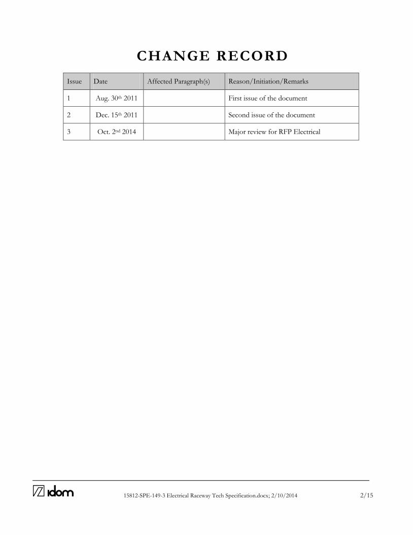
15812-SPE-149-3 Electrical Raceway Tech Specification.docx; 2/10/2014 2/15
CHANGE RECORD
Issue Date Affected Paragraph(s) Reason/Initiation/Remarks
1 Aug. 30th 2011 First issue of the document
2 Dec. 15th 2011 Second issue of the document
3 Oct. 2nd 2014 Major review for RFP Electrical

15812-SPE-149-3 Electrical Raceway Tech Specification.docx; 2/10/2014 3/15
ABBREVIATIONS AD Applicable Document ATST Advanced Technology Solar Telescope AURA Association of Universities for Research in Astronomy CO Contract Officer COTR Contract Officer Technical Representative EMC Electromagnetic Compatibility F-ATP Factory Acceptance Tests Plan FEM Finite Element Model FOV Field of View GIS Global Interlock System ICD Interface Configuration Document I/F Interface LAN Local Area Network LIC Local Interlock Controller MIP Mandatory Inspection Points N/A Not Applicable NC Not Compliant PDR Preliminary Design Review PHA Preliminary Hazards Analysis QA Quality Assurance RAMS Reliability, Availability, Maintainability and Safety RD Reference Document RFP Request for Proposal S-ATP Safety Acceptance Tests Plan SOW Statement of Work S&O Support and Operations TBD To Be Defined TBC To Be Confirmed UPS Uninterrupted Power System WBS Work Breakdown Structure WP Work Package WPD Work Package Description
15812-SPE-149-3 Electrical Raceway Tech Specification.docx; 2/10/2014 4/15
TABLE OF CONTENTS
1 SCOPE OF THE DOCUMENT ................................................................................................. 5
2 ASSUMPTIONS CONSIDERED ............................................................................................... 6
3 GENERAL ................................................................................................................................... 7
4 SUPPLY SCOPE .......................................................................................................................... 8
4.1 FACTORY TESTING ...................................................................................................................................... 8
4.2 ON SITE INSPECTION AND TESTING .................................................................................................. 8
4.3 DRAWINGS AND DOCUMENTATION .................................................................................................. 8
5 ENVIRONMENTAL CONDITIONS ON SITE ...................................................................... 10
6 PACKING AND PROTECTION DURING TRANSPORT AND STORAGE ......................... 10
6.1 MARKING ........................................................................................................................................................ 11
6.2 PACKING CONDITIONS OF EQUIPMENT ........................................................................................ 11
7 CODES AND STANDARDS ...................................................................................................... 12
7.1 GENERAL ........................................................................................................................................................ 12
7.2 OTHERS ............................................................................................................................................................ 12
7.3 REGULATION AND LEGISLATION ..................................................................................................... 12
8 TECHNICAL CHARACTERISTICS ........................................................................................ 13
8.1 CABLE TRAYS................................................................................................................................................. 13
8.2 CONDUIT ......................................................................................................................................................... 13
8.3 JUNCTION BOXES AND FITTINGS ...................................................................................................... 14
8.4 WIRING REQUIREMENTS ........................................................................................................................ 15
15812-SPE-149-3 Electrical Raceway Tech Specification.docx; 2/10/2014 5/15
1 S C OP E OF TH E D OC U M E N T
This specification defines the electrical distribution transformers for the ATST (Advanced Technology Solar Telescope) Project, Haleakala National Park, Hawaii.
15812-SPE-149-3 Electrical Raceway Tech Specification.docx; 2/10/2014 6/15
2 A S S U M P TI ONS C ONS I D ER E D
No significant assumption has been made in the last period.
15812-SPE-149-3 Electrical Raceway Tech Specification.docx; 2/10/2014 7/15
3 G E NE R AL
The supplier shall provide and install equipment in accordance with these specifications. The supplier shall provide any data required. Any changes to this specification shall be authorized by the owner in writing in advance. Approval of another drawing, design criteria, or specification shall not be construed to imply compliance with this document. The supplier shall perform each analysis, test procedure, inspection, and additional activity, as required to assure that the installation is in accordance with codes and industry standard practices, and is delivered in a complete and fully operable condition.
15812-SPE-149-3 Electrical Raceway Tech Specification.docx; 2/10/2014 8/15
4 S U P P LY S C OP E
The supplier shall adhere to the following requirements for the electrical raceway systems, including cable trays, wire duct, electrical conduit, and junction boxes.
4.1 FACTORY TESTING
Factory testing and inspections shall include the following:
Spot check physical characteristics, such as material type and size.
Verify galvanization is undamaged, and repair any scratches.
Perform electrical resistance test at junctions.
Submerge samples of raceway in saline chamber for 100 hours and verify no corrosion.
4.2 ON SITE INSPECTION AND TESTING
Site inspection and testing shall include the following:
Verify proper size.
Verify galvanization or paint are undamaged, and repair any scratches.
Perform electrical resistance test at junctions.
Perform resistance checks to verify galvanized parts are solidly grounded.
4.3 DRAWINGS AND DOCUMENTATION
The supplier shall provide general arrangement drawings which include dimensions, plan view, front view, side view, rear views, top or bottom views as required for cable routing, denotation of shipping sections, and include electrical data and weight of each piece of equipment. Drawings also to be provided shall include major assembly drawings, internal schematic drawings for accessory circuits, interconnect wiring diagrams, and other drawings as required. Final as-built drawings shall be provided after completion of site startup. Other documentation shall include:
A list of all documents.
A timetable with key dates for design, fabrication, factory testing, and delivery, to be
provided to the owner for approval for an inspection program.
Catalog cut sheets and brochures of individual components.
Bill of materials of all components within equipment, described by manufacturer, model,
designation, quantity, and characteristics.
15812-SPE-149-3 Electrical Raceway Tech Specification.docx; 2/10/2014 9/15
Factory test forms, signed and dated.
Quality certification, signed and dated.
Spare parts list, as described elsewhere in this specification.
Packing List, including quantity of shipping containers with contents described, and the
weight and dimensions of each shipping container.
Shipping procedures, handling, and storage.
Data Sheet for each equipment, as included in the annex to this specification set, to be
provided during the bidding phase.
As-built documentation, in both paper and PDF (Adobe Acrobat) formats.
15812-SPE-149-3 Electrical Raceway Tech Specification.docx; 2/10/2014 10/15
5 E NV I RO NM E NTAL C ON D I TI ON S ON S I TE
All the electrical equipment and its components shall be designated and elected to comply with the environmental conditions on site.
15812-SPE-149-3 Electrical Raceway Tech Specification.docx; 2/10/2014 11/15
6 PAC K I NG AND P ROTE C TI ON D U R I NG TR ANS P ORT AND S TOR A G E
6.1 MARKING
All components shall be identified as required to facilitate on-site assembly. Identification and a packing list for each shipping container shall be provided upon arrival on site. Packages over 150 pounds (55 kg) shall be marked with their weight in lbs and kg.
6.2 PACKING CONDITIONS OF EQUIPMENT
Materials shall be transported with proper packing, including insulating materials and wood blocks as appropriate. Do not use straw or other plant materials for packing or storage. Measures shall be taken to provide protection from corrosion, condensation, sunlight, dust, high temperatures, rough handling during transport, and salt water spray from a marine environment. Utilize polyurethane, thermoplastic, or permeable paper to wrap components that can be damaged from humidity. All construction materials, crates, shipping containers, packaging material, and observatory equipment shall be free of alien arthropods when it is delivered to the site. In particular, any wood used in pallets must be new and treated to comply with the Habitat Conservation Plan.

15812-SPE-149-3 Electrical Raceway Tech Specification.docx; 2/10/2014 12/15
7 C OD E S AND S TANDAR D S
7.1 GENERAL
Current revisions of codes and standards shall apply as of the contract date. Should revisions occur after the contract date, use of these revisions will be upon demand by the authority having jurisdiction (AHJ) or upon agreement between the supplier and the owner. It shall be the responsibility of the supplier to provide and install equipment in accordance with established common practices and current industry standards. In the event of a conflict between two established codes or standards, the most rigorous shall be applied. In the event of a difference in opinion as to the proper application of a code or standard, the opinion of the owner or the AHJ shall prevail. The following codes, regulations and standards shall considerate to design, fabricate, and supply the equipment subject to this specification. The following codes and standards shall be referenced to design, provide, and install the equipment featured in this specification: ANSI American National Standards Institute ASTM American Society for Testing Material IEEE Institute of Electrical and Electronic Engineers ISO International Standards Organization NEC National Electric Code. NEMA National Electrical Manufacturers Association NFPA National fire Protection Association UL Underwriters Laboratories, Inc.)
7.2 OTHERS
It will be taken into consideration any other local or regional code / standard. The supplier shall indicate in their proposal which codes and standards will apply to the equipment they intend to provide. Should a standard be used other than those listed above, it shall be indicated, but subject to the owner’s approval.
7.3 REGULATION AND LEGISLATION
The design, materials, installation, testing, and inspection shall be conducted in accordance with applicable state and local codes and regulations. The supplier shall be responsible to comply with all local requirements for construction, operation, and safety.
15812-SPE-149-3 Electrical Raceway Tech Specification.docx; 2/10/2014 13/15
8 TE C H NI C AL C H AR AC TE R I S TI C S
8.1 CABLE TRAYS
Horizontal fitting supports, horizontal tee supports, vertical tee supports, vertical fitting supports, Reducer fitting supports, horizontal cross supports. Cable trays shall be delivered in prefabricated straight sections. Ladder-type cable trays shall have a separation between rungs no greater than 9 inches (250 mm). The tray width shall be no less than 6 inches (150 mm) and no greater than 30 inches (750 mm). Each rung shall support up to 270 pounds (100 kg) in the center with no permanent deformation. Cable trays shall be 5 inches (120 mm) in height, and have a usable height of 4 inches (100 mm) for holding cables. Cable trays shall be provided with matching covers capable of easy installation and a minimum thickness of 1/16 inch (1.5 mm). The cable tray sides shall have a minimum thickness of 1/8 inch (3 mm), and the rungs shall have a minimum thickness of 1/16 inch (1.5 mm). After fabrication in accordance with ASTM 123-B2, cable trays and accessories shall be hot-dipped galvanized steel. For ladder-type cable trays, the end-most rung shall be round to prevent damage to cables. Basket-type cable trays are also acceptable and should be fabricated with steel rod welding. The grid of basket-type trays shall be approximately 2 inch by 4 inch (50 mm by 100 mm). Joints between different sections of basket-type trays shall only utilize the quick union system connected by screws. All required components and accessories shall be assembled on-site in accordance with the manufacturer’s recommendations.
8.2 CONDUIT
Electrical conduit used for the routing of conductors and cables shall have circular cross-section, be hot-dipped galvanized steel, have a uniform wall thickness and continuous welded seam, and a defect-free interior. Conduit shall be manufactured in accordance with ANSI C80.1 and UL 6. When flexible conduit is required, it shall be flexible metal conduit (FMC) or liquidtight flexible metal conduit (LFMC). FMC and LFMC shall have a circular cross-section and be helically wound of interlocked metal strips. Flexible conduit shall be manufactured in accordance with UL 1. FMC may be used behind walls, above suspended ceilings, and in other areas hidden from view. FMC shall not be used in the battery room or in other exposed areas. LFMC may be used in exposed areas but in lengths no longer than 18 inches. LFMC shall not be used in the battery room.
15812-SPE-149-3 Electrical Raceway Tech Specification.docx; 2/10/2014 14/15
The use of rigid polyvinyl chloride (PVC) conduit is also permitted. PVC conduit shall have circular cross-section with couplings, connectors, and fittings of compatible material. PVC conduit shall be manufactured in accordance with UL 651A. PVC shall not be used to support light fixtures, and shall not be used in exposed areas subject to damage. All conduit have have their ends reamed to remove rough edges. Conduit shall be supported at intervals not greater than 10 feet (3 m). Conduit bends may be made so long as the conduit is not damaged and the internal diameter is not effectively reduced. There shall be no more than four quarter bends (360 degrees total) between pull points of any conduit length. Connectors and threadless couplings used with conduit shall be made tight. Where conduit segments enter a box or other enclosure, a bushing shall be provided to protect the wiring from abrasion, unless the design of the enclosure is such as to afford equivalent protection. The standard length of conduit shall be 10 feet (3 m) and each end shall be threaded. Each length of conduit shall be clearly marked at least every 5 feet (1.5 m) with the conduit type or material and the manufacturer's name or trademark. The size in inches shall be clearly marked.
8.3 JUNCTION BOXES AND FITTINGS
Boxes and conduit bodies are permitted for use as outlet, device, junction, pull boxes, and hand hole enclosures. Round boxes shall not be used where conduit will be connected to the side of the box using locknuts or bushings. Metal boxes shall be grounded and bonded. Conduit bodies such as capped elbows and service-entrance elbows that enclose conductors 6 AWG or smaller, and are only intended to enable the installation of the raceway and the contained conductors, shall not contain splices, taps, or devices and shall be of sufficient size to provide free space for all conductors enclosed in the conduit body. Boxes used for light fixture connections in a ceiling shall be designed for the purpose and shall be capable of supporting a fixture of 50 lb (23 kg) minimum. If used in a wall, boxes shall be designed for the purpose and shall be market to indicate the maximum weight of the fixture permitted to be supported by the box in the wall, if other than 50 lb (23 kg). At every box used exclusively for lighting, the box shall be designed and installed so a light fixture may be attached. Boxes, conduit bodies, and fittings shall be galvanized or otherwise corrosion-resistant both inside and out, and shall be durably marked with the manufacturer's name or trademark.
15812-SPE-149-3 Electrical Raceway Tech Specification.docx; 2/10/2014 15/15
8.4 WIRING REQUIREMENTS
Runs of cable shall be installed in accordance with the National Electrical Code. Power and signal wiring shall not occupy the same raceway unless there is a metallic barrier between them. Wiring shall be installed with shielding grounded at one end only, so as not to induce ground loops. Wiring routed through a cable-wrap system shall resist cork-screwing and be capable of withstanding multiple reverse bends over the full specified lifetime of the telescope. Jacketing material shall be resistant to oil and abrasion and remain flexible at low temperatures. The jacket material shall be molded onto the conductors to eliminate any possibility of the conductors shifting inside the cable. Power and signal wiring shall be clearly and permanently labeled at both terminations. The labeling system shall be easily traceable through the system schematic diagrams provided by the supplier. Plenum-rated or riser-rated wiring may be used in air-handling spaces, but not inside ductwork. Cable trays shall be installed as a complete system. Field bends or modifications shall be made so that the electrical continuity of the cable tray system and support for the cables is maintained. Where cable trays support conductors which pass from one cable tray to another, or from a cable tray to a raceway of a different type, the distance between cable trays, or between the cable tray and the raceway or the equipment shall not exceed 6 feet (1.8 m). The conductors shall be secured to the cable tray where they enter or exit the tray, and they shall be protected by guarding from physical damage.

Enclosure Design Services for the Advanced Technology Solar Telescope (ATST)
ELECTRICAL SWITCHBOARDS TECHNICAL SPECIFICATION
IDOM Doc. N.: 15812-SPE-150 Issue: 5 Date: Nov. 19th 2014 Contract No: C22019N
Name Signature Date
Written José Antonio Acosta
Nov. 19th 2014
Revised Javier Ariño
Nov. 19th 2014
Project Manager Gaizka Murga
Nov. 19th 2014
Principal Tom Lorentz
Nov. 19th 2014
File: 15812-SPE-150-5 Electrical Switchboards Tech Specification.docx Pages: 18

15812-SPE-150-5 Electrical Switchboards Tech Specification.docx; 19/11/2014 2/18
CHANGE RECORD
Issue Date Affected Paragraph(s) Reason/Initiation/Remarks
1 Aug. 30th 2011 First issue of the document
2 Dec. 15th 2011 Second issue of the document
3 Mar. 27th 2013 Third issue of the document
4 Oct. 2nd 2014 All Major review for RFP Electrical
5 Nov. 19th 2014 Review for RFP Electrical

15812-SPE-150-5 Electrical Switchboards Tech Specification.docx; 19/11/2014 3/18
ABBREVIATIONS AD Applicable Document ATST Advanced Technology Solar Telescope AURA Association of Universities for Research in Astronomy CO Contract Officer COTR Contract Officer Technical Representative EMC Electromagnetic Compatibility F-ATP Factory Acceptance Tests Plan FEM Finite Element Model FOV Field of View GIS Global Interlock System ICD Interface Configuration Document I/F Interface LAN Local Area Network LIC Local Interlock Controller MIP Mandatory Inspection Points N/A Not Applicable NC Not Compliant PDR Preliminary Design Review PHA Preliminary Hazards Analysis QA Quality Assurance RAMS Reliability, Availability, Maintainability and Safety RD Reference Document RFP Request for Proposal S-ATP Safety Acceptance Tests Plan SOW Statement of Work S&O Support and Operations TBD To Be Defined TBC To Be Confirmed UPS Uninterrupted Power System WBS Work Breakdown Structure WP Work Package WPD Work Package Description
15812-SPE-150-5 Electrical Switchboards Tech Specification.docx; 19/11/2014 4/18
TABLE OF CONTENTS
1 SCOPE OF THE DOCUMENT ................................................................................................. 6
2 ASSUMPTIONS CONSIDERED ............................................................................................... 7
3 GENERAL ................................................................................................................................... 8
4 SUPPLY SCOPE .......................................................................................................................... 9
EQUIPMENTS................................................................................................................................................... 9
FACTORY TESTING .................................................................................................................................... 10
INSPECTIONS ON THE SITE ................................................................................................................... 11
SHIPPING AND STORAGE ....................................................................................................................... 11
TRAINING COURSES .................................................................................................................................. 11
REPLACEMENT PARTS .............................................................................................................................. 11
SPARE PARTS .................................................................................................................................................. 12
DRAWINGS AND DOCUMENTATION ................................................................................................ 12
5 ENVIRONMENTAL CONDITIONS ON SITE ...................................................................... 13
6 PACKING AND PROTECTION DURING TRANSPORT AND STORAGE ......................... 14
MARKING ........................................................................................................................................................ 14
PACKING CONDITIONS OF EQUIPMENT ........................................................................................ 14
7 CODES AND STANDARDS ...................................................................................................... 15
GENERAL ........................................................................................................................................................ 15
OTHERS ............................................................................................................................................................ 15
REGULATION AND LEGISLATION ..................................................................................................... 15
8 TECHNICAL CHARACTERISTICS ........................................................................................ 16
SERVICE CONDITIONS ............................................................................................................................. 16
SWITCHBOARD COMPONENTS ............................................................................................................ 16
FABRICATION ............................................................................................................................................... 16
NAMEPLATES ................................................................................................................................................ 17

15812-SPE-150-5 Electrical Switchboards Tech Specification.docx; 19/11/2014 5/18
CONDUCTORS AND TERMINALS ......................................................................................................... 18
SPARE ................................................................................................................................................................ 18
15812-SPE-150-5 Electrical Switchboards Tech Specification.docx; 19/11/2014 6/18
1 S C O P E OF TH E DO C U ME NT
This specification defines the electrical switchboards and panelboards for the ATST (Advanced Technology Solar Telescope) Project, Haleakala National Park, Hawaii.
15812-SPE-150-5 Electrical Switchboards Tech Specification.docx; 19/11/2014 7/18
2 AS S UM P TIO N S C O N SID E RE D
No significant assumption has been made in the last period.
15812-SPE-150-5 Electrical Switchboards Tech Specification.docx; 19/11/2014 8/18
3 G E NE RAL
The supplier shall provide and install equipment in accordance with these specifications. The supplier shall provide any data required. Any changes to this specification shall be authorized by the owner in writing in advance. Approval of another drawing, design criteria, or specification shall not be construed to imply compliance with this document. The supplier shall perform each analysis, test procedure, inspection, and additional activity, as required to assure that the installation is in accordance with codes and industry standard practices, and is delivered in a complete and fully operable condition. This document covers design engineering, fabrication, inspection, quality control, factory testing, shipping, startup, and on-site testing. It also includes training for ATST personnel and parts replacement for three (3) years after completion of startup.
15812-SPE-150-5 Electrical Switchboards Tech Specification.docx; 19/11/2014 9/18
5
4 S U P P LY SC OP E
The supplier shall adhere to the following requirements for the electrical switchgear, switchboards, and panelboards. In this specification, the word “switchboard” may also refer to switchgear or panelboard, depending on the application.
EQUIPMENTS
Equipment shall be constructed in accordance with this section, Section 8, and the drawings. This project’s switchboards are:
Designation Description
MRPS100 Main Regular Power Switchboard
MEPS100 Main Emergency Power Switchboard
MUPS100 Main UPS Power Switchboard
MRLS100 Main Enclosure Regular Lighting & Distribution
MEEL100 Main Enclosure Emergency Lighting
MELU100 Emergency lighting UPS, Generator-backed Switchboard
MEGV100 Main Vent Gates Switchboard
CABINET 602 Windows level II vent gates control cabinet II
CABINET 601 Windows level II vent gates control cabinet I
CABINET 502 Windows level I vent gates control cabinet II
CABINET 501 Windows level I vent gates control cabinet I
CABINET 402 Telescope level vent gates control cabinet II
CABINET 401 Telescope level vent gates control cabinet I
CABINET 604 Windows level II vent gates control cabinet IV
CABINET 603 Windows level II vent gates control cabinet III
CABINET 506 Windows level I vent gates control cabinet IV
CABINET 505 Windows level I vent gates control cabinet III
CABINET 404 Telescope level vent gates control cabinet IV
CABINET 403 Telescope level vent gates control cabinet III Provide all tools necessary for equipment maintenance, including tools required to insert and withdraw the breakers.
4.1.1 SCOPE OF SUPPLY
The scope shall include:
• Termination of power cables.
• Termination of other wiring (signals and auxiliaries).
• Enclosure, busbars, circuit breakers, and other such components as required.
15812-SPE-150-5 Electrical Switchboards Tech Specification.docx; 19/11/2014 10/18
• Complete assembly and testing of system.
• Foundations or other masonry required.
• Cleaning.
• Design all auxiliary equipment to ensure a proper work of the equipment.
4.1.2 EXCEPTIONS
In the bid, the supplier shall clearly indicate any exception from this specification, otherwise this specification will be considered accepted in its entirety. After bid acceptance, any changes to this specification shall be authorized by the owner in writing in advance.
FACTORY TESTING
4.2.1 GENERAL
• The supplier shall perform testing and inspection at the factory, and the owner reserves the right to witness these tests. The supplier shall notify the owner of the dates that testing will be performed at least 14 days prior to shipping.
• In the bid, the supplier shall indicate if they do not have the necessary facilities to perform the factory testing and what alternatives they propose. In all bids, the supplier shall indicate which tests would be performed at the factory and which would be handled on-site.
• If the equipment fails to pass a test, the supplier shall provide troubleshooting assistance, programming assistance, and replacement parts as required until the desired results are achieved.
• The achievement of desired test results does not exempt the supplier from warranty guarantees in the event of defects found within the warranty period.
• The supplier shall provide all test procedures, test results, and certification of passing, as described in Section 4.8. Upon satisfactory completion of testing, equipment shipment is authorized.
• On-site testing shall be performed independently of the pre-shipment factory tests, to verify satisfactory operation.
4.2.2 INSPECTIONS
The owner or owner’s representative shall have the right to inspect the equipment at any time during its fabrication at the factory, for the purpose of observing the materials and methods used. The supplier shall provide their schedule for fabrication, assembly, and test, so as to facilitate possible inspections.
4.2.3 TESTING STANDARDS
Switchboards shall be tested in accordance with UL 50, UL 67, UL 489, UL 891, and shall conform to the requirements of the National Electrical Code.
15812-SPE-150-5 Electrical Switchboards Tech Specification.docx; 19/11/2014 11/18
INSPECTIONS ON THE SITE
The final acceptance shall be done at site, after completion of site startup. Site inspection shall include, but not be limited to, the following:
• Verify the bill of materials, correct identification of components, and correct designations of switchboard assemblies.
• Verify physical characteristics including dimensions, mounting method, and paint.
• Verify insulation resistance of the main and auxiliary circuits.
• Verify safety interlocks.
• Verify correct operation of all breakers.
• Verify proper cable sizing and terminations.
• Other verification as may be described elsewhere in this specification.
SHIPPING AND STORAGE
After completion of factory testing, the shipping container shall be suitable for storage both at the factory and on-site, and as such, provisions shall be made to protect the equipment against humidity, condensation, corrosion, and other environmental factors. The supplier shall provide a description of protective methods to be used during the storage period. The shipping container shall also be suitable for transport by the vehicles intended to be used. The supplier shall be responsible for transportation to the site. Installation of the equipment into the ATST facility, connections to the building systems, and power-up will be performed by others.
TRAINING COURSES
The supplier shall provide the necessary training for ATST personnel as to the proper operation of the equipment. The supplier shall also provide an owner’s manual to include equipment drawings, catalogue cut sheets of major components, operating procedures, warranty information, and service contact information.
REPLACEMENT PARTS
The supplier shall replace any parts which may fail during start-up or within the first three years of operation.
15812-SPE-150-5 Electrical Switchboards Tech Specification.docx; 19/11/2014 12/18
SPARE PARTS
The supplier shall provide a list of recommended spare parts for each switchboard. The owner reserves the right not to purchase these parts.
DRAWINGS AND DOCUMENTATION
The supplier shall provide general arrangement drawings which include dimensions, plan view, front view, side view, rear views, top or bottom views as required for cable routing, denotation of shipping sections, and include electrical data and weight of each piece of equipment. Drawings also to be provided shall include major assembly drawings, electrical single-line diagrams, internal schematic drawings for accessory circuits, interconnect wiring diagrams, schedules, and other drawings as required. Final as-built drawings shall be provided after completion of site start-up. Other documentation shall include:
• A list of all documents.
• A timetable with key dates for design, fabrication, factory testing, and delivery, to be provided to the owner for approval for an inspection program.
• Catalogue cut sheets and brochures of individual components.
• Bill of materials of all components within equipment, described by manufacturer, model, designation, quantity, characteristics, and location in the drawings.
• Factory test forms, signed and dated.
• Quality certification, signed and dated.
• Quality certification of each component in the switchboard.
• Spare parts list, as described elsewhere in this specification.
• Packing List, including quantity of shipping containers with contents described, and the weight and dimensions of each shipping container.
• Shipping procedures, handling, and storage.
• Data Sheet for each equipment, as included in the annex to this specification set, to be provided during the bidding phase.
• As-built documentation, in both paper and PDF (Adobe Acrobat) formats.

15812-SPE-150-5 Electrical Switchboards Tech Specification.docx; 19/11/2014 13/18
5 E N VI RON M E N TAL C O N D ITIO NS ON SIT E
All the electrical equipment and its components shall be designated and elected to comply with the environmental conditions on site.
15812-SPE-150-5 Electrical Switchboards Tech Specification.docx; 19/11/2014 14/18
6 PAC K IN G AN D P ROTE C TI ON DU RI N G TRAN SP O RT A ND STO RA G E
MARKING
All components shall be identified as required to facilitate on-site assembly. Identification and a packing list for each shipping container shall be provided upon arrival on site. Packages over 150 pounds (55 kg) shall be marked with their weight in lbs and kg.
PACKING CONDITIONS OF EQUIPMENT
The equipment surface shall be protected by paint, and the paint shall be protected against damage during shipping. The inner surface shall be protected by paint, grease, or other protective method to prevent corrosion. Materials shall be transported with proper packing, including insulating materials and wood blocks as appropriate. Do not use straw or other plant materials for packing or storage. Measures shall be taken to provide protection from corrosion, condensation, sunlight, dust, high temperatures, rough handling during transport, and salt water spray from a marine environment. Utilize polyurethane, thermoplastic, or permeable paper to wrap components that can be damaged from humidity. Threaded connections shall be protected with screw-caps. The main switchgear should be shipped first, followed by other equipment in the order it is to be installed, if possible. The supplier shall include replacement parts for any components which could be anticipated to break during shipping and site installation.
15812-SPE-150-5 Electrical Switchboards Tech Specification.docx; 19/11/2014 15/18
7 C OD E S AND S TAN DARD S
GENERAL
Current revisions of codes and standards shall apply as of the contract date. Should revisions occur after the contract date, use of these revisions will be upon demand by the authority having jurisdiction (AHJ) or upon agreement between the supplier and the owner. It shall be the responsibility of the supplier to provide and install equipment in accordance with established common practices and current industry standards. In the event of a conflict between two established codes or standards, the most rigorous shall be applied. In the event of a difference in opinion as to the proper application of a code or standard, the opinion of the owner or the AHJ shall prevail. The following codes and standards shall be referenced to design, provide, and install the equipment featured in this specification: ANSI American National Standards Institute ASTM American Society for Testing Material IEEE Institute of Electrical and Electronic Engineers ISO International Standards Organization NEC National Electrical Code. NEMA National Electrical Manufacturers Association NFPA National Fire Protection Association UL Underwriters Laboratories, Inc.)
OTHERS
It will be taken into consideration any other local or regional code / standard. The supplier shall indicate in their proposal which codes and standards will apply to the equipment they intend to provide. Should a standard be used other than those listed above, it shall be indicated, but subject to the owner’s approval.
REGULATION AND LEGISLATION
The design, materials, installation, testing, and inspection shall be conducted in accordance with applicable state and local codes and regulations. The supplier shall be responsible to comply with all local requirements for construction, operation, and safety.

15812-SPE-150-5 Electrical Switchboards Tech Specification.docx; 19/11/2014 16/18
5
8 TE C HN IC AL C H ARAC T E R IST IC S
SERVICE CONDITIONS
Switchboards and other power equipment shall be connected as shown on the drawings.
SWITCHBOARD COMPONENTS
8.2.1 GENERALS
Switchboards shall be equipped with the following items:
• Main circuit breakers with thermal-magnetic trips, molded-case style, three poles, motorized.
• Power monitoring system with RS-485 protocol communication.
• Feeder or branch circuit breakers with thermal-magnetic trips, molded-case style.
• Interrupting ratings shall be as shown on drawings, or 14 kA minimum.
• Terminal lugs for power cables.
• On/Off switch for main breaker.
• All metallic parts shall be grounded to the ground bus.
• Internal control wiring.
• Terminal blocks for control wiring.
• On/Off switch for lighting circuits.
• Short-circuit current rating shall be as shown on drawings, or 14 kA minimum. The switchboard, busbars, breakers, and other components shall be braced to withstand 100% of the maximum short circuit current. Components shall be rated for 125% of the continuous service current, as required by the National Electrical Code. Switchboards manufacturer shall check cross-section of cable connected. Refer to drawing 15812-DWG-E-5.5-001. Wherever required manufacturer shall provide terminal adaptors in order to connect all the cables properly
FABRICATION
The switchboards shall be metallic, wall-mounted or free-standing, with 2 mm2 of thickness plate and closing door, with NEMA 3 enclosure. Panelboards shall be mounted in cabinets, cutout boxes, or enclosures designed for the purpose and shall be dead-front. Switchboard materials shall be moisture-resistant and non-combustible. Materials and construction of busbars and insulators shall be in accordance with UL standards.

15812-SPE-150-5 Electrical Switchboards Tech Specification.docx; 19/11/2014 17/18
Instruments, pilot lights, potential transformers, and other switchboard devices with potential coils shall be protected by overcurrent devices rated 15 amperes or less. Barriers shall be placed in all switchboards such that no uninsulated, ungrounded busbar, terminal, or cable is exposed to inadvertent contact by a person or maintenance equipment, while load terminations are being serviced. Field wiring terminals and grounding terminals shall be located so that it is not necessary to reach across an uninsulated ungrounded current-carrying component in order to make connections. The phase arrangement on 3 phase buses shall be A, B, C from front to back, top to bottom, or left to right, as viewed from the front of the switchboard or panelboard. Every circuit and circuit modification shall be legibly identified as to its clear, evident, and specific purpose or use. The identification shall include sufficient detail to allow each circuit to be distinguished from all others. Spare positions that contain unused overcurrent devices or switches shall be described accordingly. The identification shall be included in a circuit directory that is located on the face or inside of the panel door in the case of a panelboard, and located at each switch on a switchboard. No circuit shall be described in a manner that depends on transient conditions of occupancy. Panelboard cabinets and panelboard frames, if of metal, shall be in physical contact with each other and shall be connected to an equipment grounding conductor. Where the panelboard is used with non-metallic raceway or cable or where separate equipment grounding conductors are provided, a terminal bar for the equipment grounding conductors shall be secured inside the cabinet. The terminal bar shall be bonded to the cabinet and panelboard frame, if of metal; otherwise it shall be connected to the equipment grounding conductor that is run with the conductors feeding the panelboard. Each grounded conductor shall terminate in an individual terminal that is not also used for another conductor.
NAMEPLATES
Switchboards shall have nameplates on the front denoting the designation of the equipment in accordance with the drawings and Section 4.1 of this specification. Breakers and other components at the front shall also be identified with their designation and function. Nameplates shall be of plastic laminate and mounted with stainless steel screws; adhesive mounting shall not be allowed. Internal components of the switchboard shall also be clearly identified. Switchboards shall have an additional nameplate on the front with equipment ratings. Nameplates shall be of steel, aluminium, or plastic laminate, and mounted with stainless steel screws or rivets. These nameplates shall display:
• Switchboard Manufacturer.

15812-SPE-150-5 Electrical Switchboards Tech Specification.docx; 19/11/2014 18/18
• Model.
• Serial number.
• Year of manufacture.
• NEMA enclosure type.
• Rated voltage.
• Rated frequency.
• Rated current of main bus.
• Short-circuit current rating.
CONDUCTORS AND TERMINALS
Power conductors shall be of adequate length to have some slack and to fit adequately into the terminal lugs. Conductors shall be flexible copper with flame-resistant insulation, and rated for 600V. On each end, conductors shall be labelled for the equipment connected to at the other end. Terminal lugs shall be compression-type. Terminal strips shall have at least 20% spares. Cable entrances into each switchboard shall be from the top, unless denoted otherwise in the drawings.
SPARE
Switchboards shall have 30% extra space for future circuits.
T
Enclosure Design Services for the Advanced Technology Solar Telescope (ATST)
FIRE ALARM SYSTEM TECHNICAL SPECIFICATION
IDOM Doc. N.: 15812-SPE-186 Issue: 4 Date: Nov. 20th 2014
Contract No: C22019N
Name Signature Date
Written Jose Luis Periñán
Nov. 20th 2014
Revised Javier Ariño
Nov. 20th 2014
Project Manager Gaizka Murga
Nov. 20th 2014
Principal Tom Lorentz
Nov. 20th 2014
File: 15812-SPE-186-4 Fire Alarm System Technical Specification.docx

15812-SPE-186-4 Fire Alarm System Technical Specification.docx 2/34
CHANGE RECORD
Issue Date Affected Paragraph(s) Reason/Initiation/Remarks
1 Dec. 15th 2011 First issue for RFP
2 Jan. 30th 2012 - update Fire protection system description in Chapter 4.2
- update of Reference Standard list (Chapter 7)
- update Fire extinguisher characteristics in Chapter 8.8
Review after FDR
- Change extinguisher type (Chemical Dry Multipurpose to Clean Agent extinguishers), according to RID 37 from RIX listing.
3 Oct. 2nd 2014 - Update E-5.5-004 drawing
Review for RFP Electric
4 Nov. 19th 2014 - Language improvement

15812-SPE-186-4 Fire Alarm System Technical Specification.docx 3/34
ABBREVIATIONS AD Applicable Document ATST Advanced Technology Solar Telescope AURA Association of Universities for Research in Astronomy CCTV Close Circuit Television CO Contract Officer COTR Contract Officer Technical Representative ECS Enclosure Control System EMCS Enclosure Motion Control System EMC Electromagnetic Compatibility FACP Fire Alarm Control Panel FA&T Factory Assembly & Testing FM Factory Mutual Research Corp. FMS Facility Management System FDR Final Design Review GIS Global Interlock System ICD Interface Configuration Document I/F Interface IGBT Insulated Gate Bipolar Transistor LAN Local Area Network LIC Local Interlock Controller MCC Motor Control Center N/A Not Applicable NC Not Compliant NDE Non Drive End PDR Preliminary Design Review PHA Preliminary Hazards Analysis QA Quality Assurance RAMS Reliability, Availability, Maintainability and Safety RD Reference Document SA&T Site Assembly & Testing SBC Safe Brake Control SLC Signaling Line Circuits SLS Safe Limited Speed SOS Safe Operating Stop STO Safe Torque Off SS1 Safe Stop 1 SS2 Safe Stop 2 SSM Safe Speed Monitor TEOA Top End Optical Assembly TBD To Be Defined TBC To Be Confirmed UL Underwriters Laboratories Inc. VSD Video Smoke Detection
15812-SPE-186-4 Fire Alarm System Technical Specification.docx 4/34
TABLE OF CONTENTS
1 SCOPE OF THE DOCUMENT ................................................................................................. 5
2 APPLICABLE AND REFERENCE DOCUMENTS ................................................................. 6
2.1 APPLICABLE DOCUMENTS .................................................................................................................... 6
2.2 REFERENCE DOCUMENTS .................................................................................................................... 6
3 SITE CONDITIONS .................................................................................................................. 7
4 INTRODUCTION ...................................................................................................................... 8
4.1 FIRE ANALYSIS ............................................................................................................................................ 8
4.2 FIRE PROTECTION SYSTEMS .............................................................................................................. 13
5 SCOPE OF SUPPLY................................................................................................................... 18
6 EXCLUSIONS ........................................................................................................................... 20
7 CODES, STANDARDS AND REGULATIONS ........................................................................ 21
8 TECHNICAL CHARACTERISTICS ....................................................................................... 23
8.1 REMOTE FIRE ALARM CONTROL PANEL .................................................................................... 23
8.2 VOICE EVACUATION CONTROL PANEL ...................................................................................... 25
8.3 SOUNDERS (HORNS) AND STROBE LIGHTS ............................................................................... 25
8.4 ADDRESSABLE SMOKE DETECTORS ............................................................................................. 26
8.5 FIRE ALARM PULL STATIONS ............................................................................................................. 26
8.6 VIDEO SMOKE DETECTOR (VSD) SYSTEM .................................................................................. 27
8.7 WIRING AND CONDUIT. ....................................................................................................................... 28
8.8 FIRE EXTINGUISHERS ........................................................................................................................... 29
9 SUBMITTALS ........................................................................................................................... 30
10 NAMEPLATE ............................................................................................................................ 31
11 SA&T & COMMISSIONING TESTS ....................................................................................... 32
12 PACKAGING, MARKING & TRANSPORT ............................................................................ 33
13 SPARES ...................................................................................................................................... 34

15812-SPE-186-4 Fire Alarm System Technical Specification.docx 5/34
1 S C OP E OF TH E D OC U M E N T
This specification defines necessary technical requirements to supply works, transport, assembly and testing of all components that are part of the Fire Alarm System installation required for the Enclosure of the ATST (Advanced Technology Solar Telescope); at the Haleakalā National Park, Hawaii.
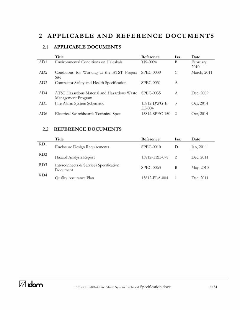
15812-SPE-186-4 Fire Alarm System Technical Specification.docx 6/34
2 AP P LI C AB LE AND R E F E R E NC E D OC U M E NTS
2.1 APPLICABLE DOCUMENTS
Title Reference Iss. Date
AD1 Environmental Conditions on Haleakala TN-0094 B February, 2010
AD2 Conditions for Working at the ATST Project Site
SPEC-0030 C March, 2011
AD3 Contractor Safety and Health Specification SPEC-0031 A
AD4 ATST Hazardous Material and Hazardous Waste Management Program
SPEC-0035 A Dec, 2009
AD5 Fire Alarm System Schematic 15812-DWG-E-5.5-004
3 Oct, 2014
AD6 Electrical Switchboards Technical Spec 15812-SPEC-150 2 Oct, 2014
2.2 REFERENCE DOCUMENTS
Title Reference Iss. Date
RD1 Enclosure Design Requirements SPEC-0010 D Jan, 2011
RD2 Hazard Analysis Report 15812-TRE-078 2 Dec, 2011
RD3 Interconnects & Services Specification Document
SPEC-0063 B May, 2010
RD4 Quality Assurance Plan 15812-PLA-004 1 Dec, 2011

15812-SPE-186-4 Fire Alarm System Technical Specification.docx 7/34
3 S I TE C OND ITI ONS
The selected site for the ATST is the Haleakalā High Altitude Observatory, located at 10000ft (3000m) in the island of Maui (HI). Haleakalā is also a cultural sensitive place for Native Hawaiians and a fragile natural environment which, linked to the remoteness of the place, recommends technical solutions that minimize the amount of work to be performed on the site. All the devices, items and tasks in the scope of this document shall be designed, selected and performed considering the environmental and working conditions stated in Environmental conditions at Haleakalã [AD1], Conditions for Working at the ATST Project Site [AD2], Contractor Safety and Health Specification [AD3] and ATST Hazardous Material and Hazardous Waste Management Program [AD4]. In particular, any equipment designed to operate at normal atmospheric air pressures or incorporating air cooling shall be de-rated for the reduced air density. (See also Packaging Chapter)
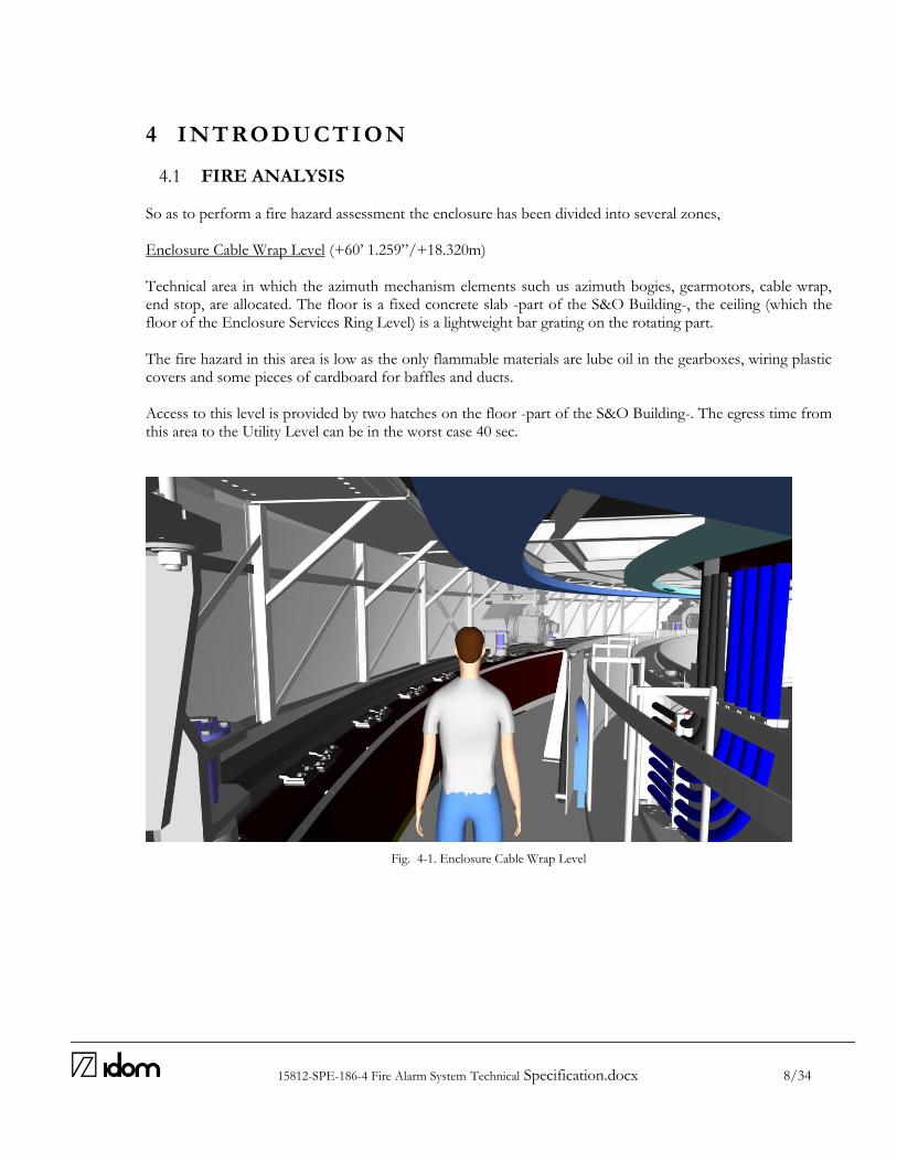
15812-SPE-186-4 Fire Alarm System Technical Specification.docx 8/34
4 I NTROD U C T I ON
4.1 FIRE ANALYSIS
So as to perform a fire hazard assessment the enclosure has been divided into several zones, Enclosure Cable Wrap Level (+60’ 1.259”/+18.320m) Technical area in which the azimuth mechanism elements such us azimuth bogies, gearmotors, cable wrap, end stop, are allocated. The floor is a fixed concrete slab -part of the S&O Building-, the ceiling (which the floor of the Enclosure Services Ring Level) is a lightweight bar grating on the rotating part. The fire hazard in this area is low as the only flammable materials are lube oil in the gearboxes, wiring plastic covers and some pieces of cardboard for baffles and ducts. Access to this level is provided by two hatches on the floor -part of the S&O Building-. The egress time from this area to the Utility Level can be in the worst case 40 sec.
Fig. 4-1. Enclosure Cable Wrap Level
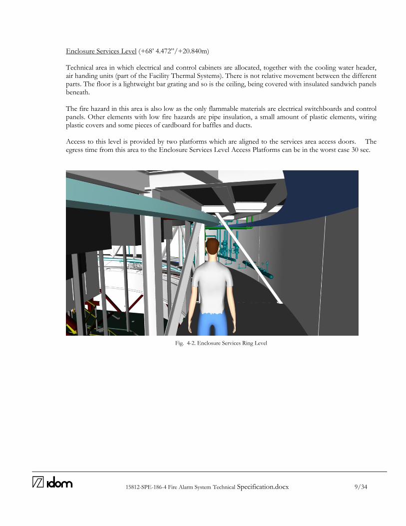
15812-SPE-186-4 Fire Alarm System Technical Specification.docx 9/34
Enclosure Services Level (+68’ 4.472”/+20.840m) Technical area in which electrical and control cabinets are allocated, together with the cooling water header, air handing units (part of the Facility Thermal Systems). There is not relative movement between the different parts. The floor is a lightweight bar grating and so is the ceiling, being covered with insulated sandwich panels beneath. The fire hazard in this area is also low as the only flammable materials are electrical switchboards and control panels. Other elements with low fire hazards are pipe insulation, a small amount of plastic elements, wiring plastic covers and some pieces of cardboard for baffles and ducts. Access to this level is provided by two platforms which are aligned to the services area access doors. The egress time from this area to the Enclosure Services Level Access Platforms can be in the worst case 30 sec.
Fig. 4-2. Enclosure Services Ring Level

15812-SPE-186-4 Fire Alarm System Technical Specification.docx 10/34
Telescope Level (+76’ 4.339”/+23.275m) Part of the telescope chamber in which the telescope equipment is allocated. The floor is composed of three different rings with relative movement and generally insulated. The outer ring is part of the Enclosure and rotates with it, the intermediate ring is part of the S&O Building and is fixed and in the inner floor is part of the Telescope Mount Assembly and rotates with the Telescope. No significant fire hazards have been detected in this area, nevertheless as the degree of knowledge of the S&O Building and Telescope Mount Assembly contract is low an additional assessment by the teams in charge of those elements would be required. Particular attention should be paid to the forklift and articulated boom lift that operate in the telescope chamber. Access to this area is provided by a staircase and an elevator in the S&O Building part of the floor. The egress time from this area to this staircase can be in the worst case 15 sec. Two additional exit doors allow access from this level to the outside catwalk. However they are not considered emergency exit doors.
Fig. 4-3. Telescope Level

15812-SPE-186-4 Fire Alarm System Technical Specification.docx 11/34
Maintenance Walkways (+84’ 8.496”/+25.819m and above) Maintenance walkways providing access to the Ventilation Gates, TEAO Platform, Bridge Crane / Jib Crane Maintenance Areas. The floor is generally a lightweight bar grating. The fire hazard in this area is low as the only flammable materials are electrical switchboards and control panels. Other elements with low fire hazards are pipe insulation, an small amount of plastic elements, wiring plastic covers and some pieces of cardboard for baffles and ducts. Access to this areas is provided by a system of staircases from the Telescope Level. The egress time from this area to the Telescope Level can be in the worst case 90 sec.
Fig. 4-4. Maintenance Walkways

15812-SPE-186-4 Fire Alarm System Technical Specification.docx 12/34
Fig. 4-5. Maintenance Walkways
Fig. 4-6. Emergency Routes Drawing
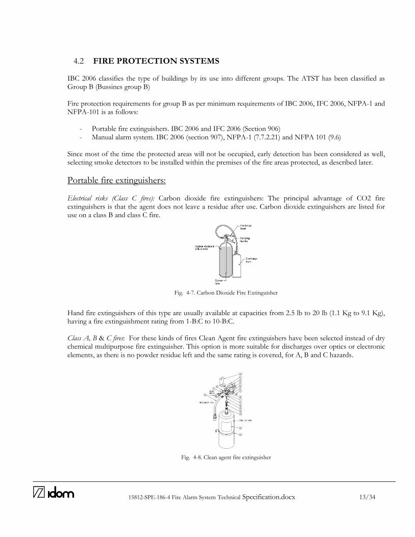
15812-SPE-186-4 Fire Alarm System Technical Specification.docx 13/34
4.2 FIRE PROTECTION SYSTEMS
IBC 2006 classifies the type of buildings by its use into different groups. The ATST has been classified as Group B (Bussines group B) Fire protection requirements for group B as per minimum requirements of IBC 2006, IFC 2006, NFPA-1 and NFPA-101 is as follows:
- Portable fire extinguishers. IBC 2006 and IFC 2006 (Section 906) - Manual alarm system. IBC 2006 (section 907), NFPA-1 (7.7.2.21) and NFPA 101 (9.6)
Since most of the time the protected areas will not be occupied, early detection has been considered as well, selecting smoke detectors to be installed within the premises of the fire areas protected, as described later.
Portable fire extinguishers: Electrical risks (Class C fires): Carbon dioxide fire extinguishers: The principal advantage of CO2 fire extinguishers is that the agent does not leave a residue after use. Carbon dioxide extinguishers are listed for use on a class B and class C fire.
Fig. 4-7. Carbon Dioxide Fire Extinguisher
Hand fire extinguishers of this type are usually available at capacities from 2.5 lb to 20 lb (1.1 Kg to 9.1 Kg), having a fire extinguishment rating from 1-B:C to 10-B:C. Class A, B & C fires: For these kinds of fires Clean Agent fire extinguishers have been selected instead of dry chemical multipurpose fire extinguisher. This option is more suitable for discharges over optics or electronic elements, as there is no powder residue left and the same rating is covered, for A, B and C hazards.
Fig. 4-8. Clean agent fire extinguisher
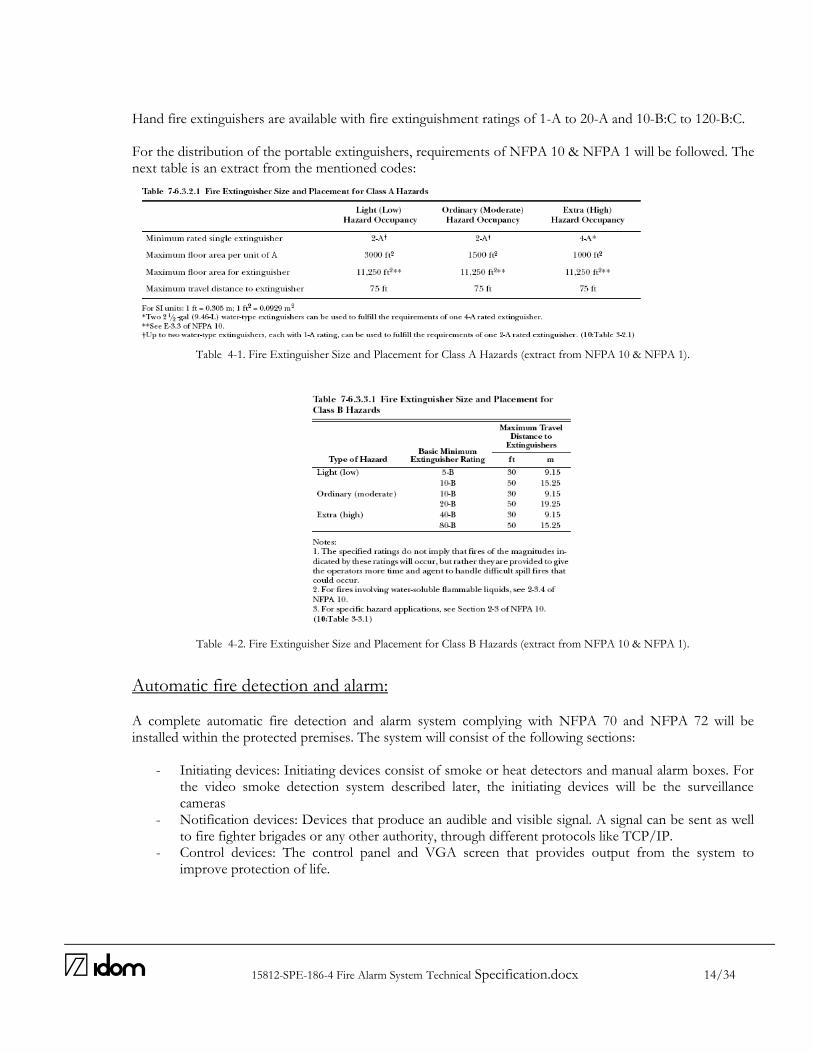
15812-SPE-186-4 Fire Alarm System Technical Specification.docx 14/34
Hand fire extinguishers are available with fire extinguishment ratings of 1-A to 20-A and 10-B:C to 120-B:C. For the distribution of the portable extinguishers, requirements of NFPA 10 & NFPA 1 will be followed. The next table is an extract from the mentioned codes:
Table 4-1. Fire Extinguisher Size and Placement for Class A Hazards (extract from NFPA 10 & NFPA 1).
Table 4-2. Fire Extinguisher Size and Placement for Class B Hazards (extract from NFPA 10 & NFPA 1).
Automatic fire detection and alarm: A complete automatic fire detection and alarm system complying with NFPA 70 and NFPA 72 will be installed within the protected premises. The system will consist of the following sections:
- Initiating devices: Initiating devices consist of smoke or heat detectors and manual alarm boxes. For the video smoke detection system described later, the initiating devices will be the surveillance cameras
- Notification devices: Devices that produce an audible and visible signal. A signal can be sent as well to fire fighter brigades or any other authority, through different protocols like TCP/IP.
- Control devices: The control panel and VGA screen that provides output from the system to improve protection of life.
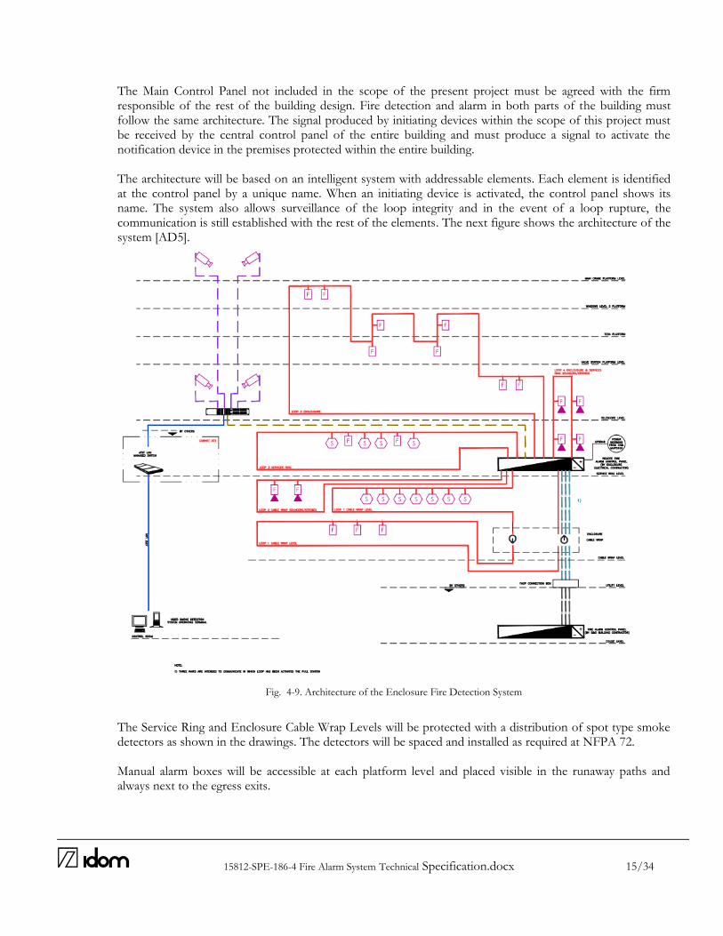
15812-SPE-186-4 Fire Alarm System Technical Specification.docx 15/34
The Main Control Panel not included in the scope of the present project must be agreed with the firm responsible of the rest of the building design. Fire detection and alarm in both parts of the building must follow the same architecture. The signal produced by initiating devices within the scope of this project must be received by the central control panel of the entire building and must produce a signal to activate the notification device in the premises protected within the entire building. The architecture will be based on an intelligent system with addressable elements. Each element is identified at the control panel by a unique name. When an initiating device is activated, the control panel shows its name. The system also allows surveillance of the loop integrity and in the event of a loop rupture, the communication is still established with the rest of the elements. The next figure shows the architecture of the system [AD5].
Fig. 4-9. Architecture of the Enclosure Fire Detection System
The Service Ring and Enclosure Cable Wrap Levels will be protected with a distribution of spot type smoke detectors as shown in the drawings. The detectors will be spaced and installed as required at NFPA 72. Manual alarm boxes will be accessible at each platform level and placed visible in the runaway paths and always next to the egress exits.
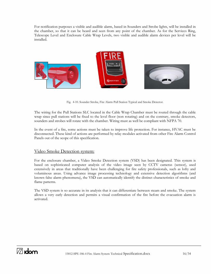
15812-SPE-186-4 Fire Alarm System Technical Specification.docx 16/34
For notification purposes a visible and audible alarm, based in Sounders and Strobe lights, will be installed in the chamber, so that it can be heard and seen from any point of the chamber. As for the Services Ring, Telescope Level and Enclosure Cable Wrap Levels, two visible and audible alarm devices per level will be installed.
Fig. 4-10. Sounder Strobe, Fire Alarm Pull Station Typical and Smoke Detector.
The wiring for the Pull Stations SLC located in the Cable Wrap Chamber must be routed through the cable wrap since pull stations will be fixed to the level floor (non rotating) and on the contrary, smoke detectors, sounders and strobes will rotate with the chamber. Wiring must as well be compliant with NFPA 70. In the event of a fire, some actions must be taken to improve life protection. For instance, HVAC must be disconnected. These kind of actions are performed by relay modules activated from other Fire Alarm Control Panels out of the scope of this specification.
Video Smoke Detection system: For the enclosure chamber, a Video Smoke Detection system (VSD) has been designated. This system is based on sophisticated computer analysis of the video image seen by CCTV cameras (sensor), used extensively in areas that traditionally have been challenging for fire safety professionals, such as lofty and voluminous areas. Using advance image processing technology and extensive detection algorithms (and known false alarm phenomena), the VSD can automatically identify the distinct characteristics of smoke and flame patterns. The VSD system is so accurate in its analysis that it can differentiate between steam and smoke. The system allows a very early detection and permits a visual confirmation of the fire before the evacuation alarm is activated.
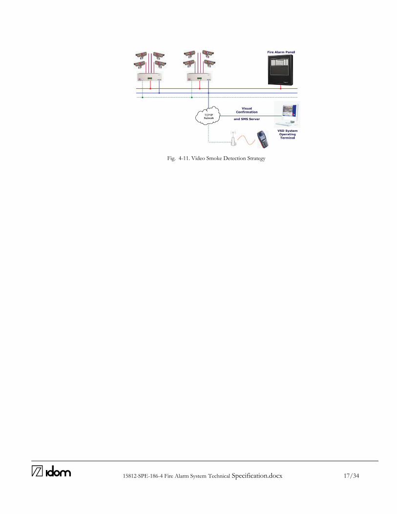
15812-SPE-186-4 Fire Alarm System Technical Specification.docx 17/34
Fig. 4-11. Video Smoke Detection Strategy

15812-SPE-186-4 Fire Alarm System Technical Specification.docx 18/34
5 S C OP E OF SU P P LY
The supplier of this part of the Fire Alarm System will be responsible for the complete engineering, supply, erection, programming, testing and start-up untill the correct operation of the Enclosure Fire Alarm System. The scope of supply referred in this section shall include, but not be limited to, alarm initiating devices, alarm notification appliances, Fire Alarm Control Panel (FACP), auxiliary control devices, fire extinguishers and wiring, as described in this Technical Specification, which has been schematically represented in the Fire Alarm Architecture scheme [AD5]. All the applicable documents [AD] and reference documents [RD] designated in Chapter 2 are part of the present specification thus are applicable for the supply. This subsystem will be a part of an overall ATST Fire Alarm System. The scope of supply of this specification only refers to elements located in the Services Ring, Enclosure Cable Wrap Chamber and Enclosure Telescope Chamber and their wired connections. No relay actuation is expected from the Remote Fire Alarm Control Panel hereby specified. In case some initiating device is actuated at any of the mentioned areas, smoke fire detection signals will be communicated to other Remote Fire Alarm Panel (out of the scope from this supply).
Supplied Equipment shall be in full accordance with this Specification and attachments (apart of approved deviations, if there are) and applicable/referenced Codes and Standards.
The U.S. units shall be the official Contractual System to express units of measurement. Exception can be considered in wiring quantities.
The scope of supply includes at least, the following:
Remote Fire Alarm Control Panel
Voice Evacuation Control Panel
Sounders (Horns) and Strobes
Addressable smoke Detectors
Fire Alarm Pull Stations
Video Smoke Detector (VSD) System
Wiring and conduit for inter connexion of the different components.
All necessary and auxiliary elements for proper operation of equipment (except expressly mentioned services in the exclusions section).
Supply of anchor elements.
Submittals (Manuals, Drawings, etc.)
Packing operations, marked, insurances and transportation necessary for its supply in Maui
Technical specification for assembly and commissioning. (No supervision required)
Special tools for the erection, start-up and maintenance of the installation if needed.
Spares for commissioning and maintenance.
Nameplate of Control Panels.
Power supply connections at Remote FACP (Service Ring Level)
UPS Power Supply
15812-SPE-186-4 Fire Alarm System Technical Specification.docx 19/34
It will also be part of supply any other equipment, material, document and/or service not specifically indicated at previous points, but necessary for a reliable and safe operation of equipment or required for its legalization in front of the authority having jurisdiction. In the same way, support, training and the necessary material for mounting and the start-up will be also included in the scope.
Vendor will make the opportune suggestions for additional elements required for legal compliance and for improvement and optimization of equipment specification for its proper maintenance and therefore the prolongation of its useful life.
In order to achieve a higher level of integration of the Enclosure and S&O Alarm Systems, the Fire Alarm Systems connection may be revised if appropriate and carried out by the Fire Alarm System Installer(s), subject to approval by AURA and the Enclosure and S&O Building Designers.
For equipment other than that specified, the contractor shall supply proof that such substitute equipment equals or exceeds the features, functions, performance, and quality of the specified equipment. The limits included in the supply are:
Bring Alarm signals via voltage free open contacts from FACP to FACP Connection Box (at Utility Level).
Furthermore, complete maintenance and repair service for the fire alarm system shall be available from a factory trained authorized representative of the manufacturer of the major equipment. The inclusion of this service should be agreed with a single maintenance service for the whole Fire Alarm System, including VSD System.
15812-SPE-186-4 Fire Alarm System Technical Specification.docx 20/34
6 E XC LU S I ONS
The following materials, equipment and services will be furnished by others:
Civil works.
FACP (Coude Level) Power supply and wiring to FACP Connection Box.
Field assembly supervision unless specified or recommended by vendor.
Unload, site discharge and storage.
15812-SPE-186-4 Fire Alarm System Technical Specification.docx 21/34
7 C OD E S , S TANDAR D S AND R E G U LATI ONS
All the codes and standards shall be applicable in the revision current at the time of signing the contract. The application of the annex or revisions of these codes and standards, published after to sign the contract, shall be agreement between the supplier and the buyer. The supplier shall identify in writing to IDOM and AURA any discrepancy that is present between the particular characteristics of their supply and the requirements of this specification from the correspondent equipment, as well as the established on codes, regulations and standards. In the case of a conflict between the criteria of this specification and the established on local codes and standards, the most rigorous of these shall apply. In case of discrepancy in the requirements where an interpretation is to apply, the buyer will judge this and his opinion shall prevail. The following codes, regulations and standards shall be considered with respect to materials, design, manufacturing, tests, transport, erection, and commissioning of the equipment included in this specification, as applicable:
National Fire Protection Association (NFPA) Standards:
NFPA 12 CO2 Extinguishing Systems (low and high)
NFPA 17 Dry Chemical Extinguishing Systems
NFPA 2001 Standard on Clean Agent Fire Extinguishers System
NFPA 72 National Fire Alarm Code
NFPA 101 Life Safety Code
Underwriters Laboratories Inc (UL) USA Standards:
The system shall be listed and approved by Underwriters Laboratories Inc (UL) and Factory Mutual Research Corp. (FM)
UL No. 268 Smoke Detectors for Fire Protective Signaling Systems
UL No. 864 Control Units for Fire Protective Signaling Systems
UL No. 464 Audible Signaling Appliances
UL No. 38 Manually Actuated Signaling Boxes
EN 61000 Series, “Electromagnetic compatibility (EMC)”, in particular the EN 61000-6-2:2001 Immunity standard for industrial environments.
IEEE 1143-1994 Guide on shielding practice for low voltage cables.
NEC – National Electrical Code: NEC 2008
ANSI /IEC 60529-2004 American National Standard for Degrees of Protection Provided by Enclosures (IP Code) (Identical National Adoption)
ASHRAE: American society of heating, refrigerating and air conditioning engineers.
Systems piping designed according to ASME B31.9
FCC Federal Communications Commission: Title 47 of the Code of Federal Regulation Part 15
Local and State Building Codes.
All requirements of the Authority Having Jurisdiction.
Any code or international equivalent standards which refers to the equipment to be supplied, shall apply, even if not mentioned in in the previous list.

15812-SPE-186-4 Fire Alarm System Technical Specification.docx 22/34
The supplier will indicate in their proposal which codes and standards related previously apply to their scope of supply; as well as the codes that will be used in the design, fabrication and test of their equipment, as well the maintenance and installation for approval from the buyer. The codes to be considered in each part from the scope of this specification, shall be compatible with each other. All local Safety and Health applicable standards and codes shall be respected. The supplier shall offer a design that will take the security measurements necessary to guarantee safe operation in normal conditions, as well as any transitory, partial charge, etc. (including a shutdown period to maintenance).
The design, materials, fabrication, transport, construction, inspection, test and preparation from the supply equipment, shall be in accordance with the applicable regulations and legislation of the United States of America, the national , local, that be applicable, codes, criteria and directives. All US regulation and legislation, in force at the time of signing of the contract, shall apply, as well as any other legislation or regulation published after the contract signature which will affect these regulations and legislation. The economic agreement of this requirement shall be a goal to be agreed between the supplier and buyer. The installation that is specified, and therefore, the design, fabrication, transport, assembly, test and start up, and in general, all the activities specified in this document, or that realized as consequence of them, shall be in accordance and accomplished within the regulation and legislation applied in the project. Nothing in this specification relives the supplier the burden of accomplishing the work within the codes and standards.

15812-SPE-186-4 Fire Alarm System Technical Specification.docx 23/34
8 TE C H NI C AL C H AR AC TE R I S TI C S
All equipment and components shall be new, and the manufacturer's current model. The materials, appliances, equipment and devices shall be tested and listed by a nationally recognized approvals agency for use as part of a protective signaling system, meeting the National Fire Alarm Code. Installation shall be in accordance with the NEC, NFPA 72, local and state codes, as shown on the drawings, and as recommended by the major equipment manufacturer. In the case where a supplier’s proposal will not fulfill any of the requirements included in this Technical Specification, the Contractor shall specifically indicate to AURA in order to assess if the proposed alternative is acceptable.
8.1 REMOTE FIRE ALARM CONTROL PANEL
The Remote FACP shall be a NOTIFIER Model NFS320-SYS or similar and shall contain a microprocessor based Central Processing Unit (CPU) and power supply in an economical space saving single board design. The CPU shall communicate with and control the following types of equipment used to make up the system: intelligent addressable smoke detectors, fire alarm pull stations, sounders, strobe lights, voice evacuation control panel and Central Control VSD Analysis Unit. The control panel shall be capable to integrate SLC’s of at least of 250 intelligent/addressable devices. It shall include Class B (NFPA Style Y) or Class A (NFPA Style Z) programmable Notification Appliance Circuits. The system shall be programmable, configurable, and expandable in the field without the need for special tools, P-ROM programmers or PC based programmers. It shall not require replacement of memory ICs to facilitate programming changes. The system shall allow the programming of any input to activate any output or group of outputs. Systems that have limited programming (such as general alarm), have complicated programming (such as a diode matrix), or require a laptop personal computer are not considered suitable substitutes. The FACP shall support logic equations and time delay equations to be used for advanced programming. The FACP shall provide the following features:
Drift compensation to extend detector accuracy over life.
Detector sensitivity test, meeting requirements of NFPA 72, Chapter
Maintenance alert to warn of excessive smoke detector dirt or dust accumulation.
Nine sensitivity levels for alarm, selected by detector.
The ability to display or print system reports.
Alarm verification, with counters and a trouble indication.
In case of proposing Positive Alarm Sequence (PAS) Capacity, shall meet NFPA 72 requirements.
Manual station reporting shall activate notification circuits within 10 seconds of initiating device activation.

15812-SPE-186-4 Fire Alarm System Technical Specification.docx 24/34
Periodic detector test, conducted automatically by the software.
Capacity for element disabling.
Point Read (device status, type, analog detector values, etc.)
System History Recording and Reporting
Device blink control for sleeping areas.
Day/night automatic adjustment of detector sensitivity. The control panel shall be housed in a UL listed cabinet suitable for surface mounting. The cabinet and front shall be corrosion protected. The back box and door shall have provisions for electrical conduit connections into the sides and top. The door shall provide a key lock and shall include a glass or other transparent opening for viewing of all indicators. The high speed microprocessor shall communicate with monitor and control all external interfaces. It shall include an EPROM for system program storage, Flash memory for building specific program storage, and a "watch dog" timer circuit to detect and report microprocessor failure. CPU shall receive analog information from all intelligent detectors to be processed to determine whether normal, alarm, prealarm, or trouble conditions exist for each detector. The system shall support a Liquid Crystal Display (LCD) with a full PC style keypad. Display with character length enough to identify at first sight the notification information. The character display shall include the following operator control switches: ACKNOWLEDGE, ALARM SILENCE, ALARM ACTIVATE (DRILL), SYSTEM RESET, and LAMP TEST and shall provide LEDs, to indicate the status of the following system parameters: AC POWER, FIRE ALARM, PREALARM WARNING, SECURITY ALARM, SUPERVISORY SIGNAL, SYSTEM TROUBLE, DISABLED POINTS, ALARM SILENCED, CONTROLS ACTIVE, PREDISCHARGE, DISCHARGE and ABORT. When a fire alarm condition is detected and reported by one of the system initiating devices, the following functions shall immediately occur:
The system alarm LED on the system display shall flash.
A local signal in the control panel shall sound.
A backlit LCD display shall indicate all information associated with the fire alarm condition, including the type of alarm point and its location within the protected premises.
History storage equipment shall log the information associated each new fire alarm control panel condition, along with time and date of occurrence.
The associated system outputs (Sounders and Strobe lights) shall be activated.
Alarm Signal shall be communicated to the other FACP communicated. The FACP shall be capable of communicating on the ATST Local Area Network (LAN). Password capability shall be provided to prevent unauthorized system control or programming.

15812-SPE-186-4 Fire Alarm System Technical Specification.docx 25/34
The main power supply shall operate on 120 VAC, 60 Hz. From the FACP each SLC interface shall provide power to and communicate with up to 150 devices. SLC shall be capable of NFPA 72 Style 6, Class A wiring. The required wiring from the FACP to the addressable power supply shall be a single twisted shielded pair wire. Data on the SLC shall be transmitted providing 6.0 amps of 24 volt DC. Overcurrent protection shall be provided on all power outputs. In the event of a power supply trouble condition, the Fire Alarm Control Panel shall report the incident and the applicable address to the FACP via the SLC. Unless otherwise required by supplier, Fire Protection Standards or local regulations, alternative power supply is planned to be done via UPS, located in the Services Ring. This UPS power supply connection is out of the scope of this technical specification.
8.2 VOICE EVACUATION CONTROL PANEL
The Voice Evacuation Control Panel shall be a NOTIFIER NFV25/ 50 (Fire Voice 25/50) or similar and shall contain a microprocessorbased Central Processing Unit (CPU). The CPU shall distribute and control emergency voice messages over the sounder circuits. The system shall provide the capability to interface to distributed voice evacuation control panels from the same manufacturer.
It shall have as minimum requirements integral 25 Watt, audio amplifier with optional converter for other volt systems. The system shall be capable of expansion via the insertion of an additional audio amplifier module into the same cabinet.
The Integral Digital Message Generator shall be capable of producing of at least four distinct messages (12 seconds each) which shall field programmable without the use of additional equipment.
Speaker/Sounder circuit shall be wired Class A or B.
8.3 SOUNDERS (HORNS) AND STROBE LIGHTS
Technical specifications required for Programmable Electronic Sounders are:
Electronic sounders shall operate on 24 VDC nominal.
Electronic sounders shall be field programmable without the use of special tools, at a sound level of 90 dBA measured at 10 feet from the device.
Shall be flush or surface mounted. Strobe lights:
Strobe lights shall meet the requirements of the ADA, UL Standard 1971 and be fully synchronized
Strobe intensity shall meet the requirements of UL 1971.
The flash rate shall meet the requirements of UL 1971.
15812-SPE-186-4 Fire Alarm System Technical Specification.docx 26/34
8.4 ADDRESSABLE SMOKE DETECTORS
Photoelectric addressable spot type smoke detectors have been designated (ionization detectors preferably avoided) to measure smoke density and shall, on command from the control panel, send data to the panel representing the analog level of smoke density. Technical specifications required for Photoelectric Smoke Detectors are:
Photoelectric smoke detectors shall be a two wire, 24 VDC type, within a voltage range between 15 and 32 volts DC.
According to space available at different Telescope Chambers, they shall be ceilingmounted, using an LED light source.
These LEDs shall flash at least every 10 seconds, indicating that power is applied to the detector.
The intelligent detectors shall have at least six sensitivity levels.
The detector screen and cover assembly shall be easily removable for field cleaning of the detector chamber.
Detector shall not require other cleaning requirements than those listed in NFPA 72. Replacement, refurbishment or specialized cleaning of the detector head shall not be required.
All field wire connections shall be made to the base through the use of a clamping plate and screw.
Each smoke detector shall be mounted on a single base and can be mounted in either flanged or flangeless bases depending on junction box selection.
Detectors and bases shall have fully coated circuit boards and superior RF/transient protection. With At least 94-V0 plastic flammability rating.
All equipment shall be attached to walls and ceiling/floor assemblies and shall be held firmly in place (e.g., detectors shall not be supported solely by suspended ceilings). Fasteners and supports shall be adequate to support the required load.
8.5 FIRE ALARM PULL STATIONS
Addressable manual fire alarm boxes shall, on command from the control panel, send data to the panel representing the state of the manual switch and the addressable communication module status. They shall use a key operated test reset lock, and shall be designed so that after actual emergency operation, they cannot be restored to normal use except by the use of a key. Technical specifications required for Manual Fire Alarm Stations are:
Manual fire alarm stations shall be addressable, nonbreakglass type, equipped with key lock so that they may be tested without operating the handle.
Stations must be designed such that after an actual activation, they cannot be restored to normal except by key reset.
Manual alarm boxes will be accessible at each platform level and placed visible in the runaway paths and always next to the egress exits.
Manual fire alarm boxes shall be installed not less than 42 inches [1067 mm], nor more than 48 inches [1220 mm] above the finished floor.
Fire alarm pulls station identification signs shall be field located on walls next to fire alarm pulls station considering evacuation routes.

15812-SPE-186-4 Fire Alarm System Technical Specification.docx 27/34
Manual stations shall be constructed of high impact resistant materials, with operating instructions provided on the cover. The word FIRE shall appear on the manual station in letters one half inch (12.7 mm) in size or larger.
8.6 VIDEO SMOKE DETECTOR (VSD) SYSTEM
The principle of operation shall be based on a unit dedicated to the task of Video Fire Detection, running no additional software providing continuous analysis of video images i.e. the field of view covered by four closed circuit television (CCTV) cameras. The unit shall allow zones to be placed anywhere within a camera view to enable the source of a fire to be identified in the shortest time possible.
The Central Control VSD Analysis Unit shall have 8 camera inputs and shall employ algorithms to process video information from four cameras simultaneously, monitoring the cameras connected.
The system shall provide the facility to allow smoke detection in one image to be treated as a pre-alarm and smoke in two associated camera images to be treated as a full alarm.
The system shall be capable of Distributing fire events to both the Remote Fire Alarm Control Panel included in this Technical Specification’s scope and communication to the Control Room via the ATST Lan Network. The system shall be able to provide distributed video feeds in real-time with pre-alarm information and visual smoke overlay to identify the risk area for operator analysis.
The system shall have capacity for storage of all fire events with adjustable pre and post-alarm on the VSD unit. It should store a minimum of 5000 date and time stamped video files which contain full resolution MJPEG. All event video storage shall meet evidential standards to provide evidence in a court of law. All footage must be stored in MJPEG with MD5 algorithm for watermarking.
The proprietary software for detecting Fire must be dedicated to its task and must be installed on a proprietary platform.
The VSD unit must have full watchdog capability to automatically restore the system without the need for any personnel intervention.
Password capability shall be provided to prevent unauthorized system control or programming.
Standby power will be required for both cameras and VSD units in the event of power failure for a period, as recommended by NFPA72 or national standard.
The system shall automatically detect video signal loss, low light level and low contrast level.
The system alarm log shall have the ability to allow per camera viewing of the alarms.
The system shall have identification text for all cameras connected to the system. It has been envisaged the use of High resolution, highly sensitive CCTV Cameras with backlight compensation and automatic exposure. The main power supply for the Video Smoke Detection System shall provide 3 amps to the VSD Central Control Unit, 120 VAC, 60 Hz. The power to the CCTV Cameras shall be supplied from the processor providing 3 to 8 W via single Twisted Shielded Pair Wire.
Video output: Twisted Shielded Pair. Converter from Coaxial RG-59 Wire to TSP integrated.
Any cameras or cabling chosen for integration with the VSD unit shall be verified by the manufacturer.
The CCTV supply shall ensure that provision is made within the VSD system for interface provision between appropriate alarm manufacturers equipment.
15812-SPE-186-4 Fire Alarm System Technical Specification.docx 28/34
Overcurrent protection shall be provided on all power outputs.
The final detailed location of cameras will be decided by AURA following agreement with the VSD Specialist & CCTV supplier.
All cameras shall be properly supported and shall be held firmly in place. Fasteners and supports shall be adequate to support the required load.
8.7 WIRING AND CONDUIT.
Wiring shall be in accordance with local, state and national codes (e.g., NEC Article 760) and as recommended by the manufacturer of the fire alarm system. Number and size of conductors shall be as recommended by the fire alarm system manufacturer, but not less than 18 AWG (1.02 mm) for Initiating Device Circuits and Signaling Line Circuits, and 14 AWG (1.63 mm) for Notification Appliance Circuits. Wire and cable not installed in conduit shall have a fire resistance rating suitable for the installation as indicated in NFPA 70. Wiring used for the multiplex communication circuit (SLC) shall be twisted and shielded and support a minimum wiring distance of 12,500 feet. All fire alarm system wiring shall be new. All field wiring shall be electrically supervised for open circuit and ground fault. The fire alarm control panel, Voice Evacuation Control Panel and VSD Central Control Unit shall be grounded securely to grounding rod, according to 15812-SPEC-150-2 Electrical Switchboards Technical Spec [AD6]. On Style 6 or 7 (Class A) configurations a single ground fault or open circuit on the system Signaling Line Circuit shall not cause system malfunction, loss of operating power or the ability to report an alarm. Alarm signals arriving at the FACP shall not be lost following a primary power failure (or outage) until the alarm signal is processed and recorded. Sounder circuits and control equipment shall be arranged such that loss of any one (1) sounder circuit will not cause the loss of any other sounders circuit in the system. Conduit shall be in accordance with The National Electrical Code (NEC), local and state requirements. Cable must be separated from any open conductors of power, or Class 1circuits, and shall not be placed in any conduit, junction box or raceway containing these conductors, per NEC Article 76055. Conduit shall not enter the fire alarm control panel, or any other remotely mounted control panel equipment or backboxes, except where conduit entry is specified by the FACP manufacturer. It has been envisaged the use of Twisted Shielded Pair Wire for signal transferring from cameras to the VSD Central Control Unit, as converters from Coaxial RG-59 Wire to TSP are integrated in the dedicated cameras. The VSD Systems physical and operational links to the Fire detection and alarm control panel shall be made via dedicated Ethernet wire Cat. 5 from the VSD unit contacts. Wire chosen for integration with the VSD unit may be revised by the manufacturer if appropriate, subject to approval by AURA and the Enclosure Building Designer.

15812-SPE-186-4 Fire Alarm System Technical Specification.docx 29/34
8.8 FIRE EXTINGUISHERS
Carbon dioxide portable fire extinguishers for use on Class B & C fire.
Hand fire extinguishers of this type proposed with 20 lb. capacity.
Fire extinguishment rated Capacity 10B:C
This kind of fire extinguishers will be installed in the proximities of switchboards and control panels. Clean agent fire extinguishers for use on Class A, B & C fires
Agent: HCFC Blend B (Halotron I), HFC-236fa (FE-36) (or similar)
Hand fire extinguishers of this type proposed with 15.5 and 13.3 lb. capacity respectively.
Fire extinguishment rated Capacity 2A:10B:C (same rate for both agents)
This kind of fire extinguishers will be installed in the proximities of optics or electronic elements. Fire extinguishers identification signs shall be field located on walls next to fire extinguishers considering evacuation routes. For the distribution of the portable extinguishers, requirements of NFPA 10 & NFPA 1 will be followed.

15812-SPE-186-4 Fire Alarm System Technical Specification.docx 30/34
9 S U B M I TTALS
Sufficient information, clearly presented, shall be included to determine compliance with drawings and specifications. Supplier shall include:
manufacturer's name(s)
model numbers
ratings
power requirements
equipment layout
device arrangement
wiring diagrams indicating internal wiring for each device
annunciator layout
configurations
terminations Supplier should submit simultaneously with the shop drawings, complete operating and maintenance manuals listing the manufacturer's name(s), including technical data sheets. Together with the shop drawing submittal, submit a certification from the major equipment manufacturer indicating that the proposed supervisor of the installation and the proposed performer of contract maintenance is an authorized representative of the major equipment manufacturer. Include names and addresses in the certification. All work performed and all material and equipment furnished under this contract shall be free from defects and shall remain so for a period of at least one (1) year from the date of acceptance. The full cost of maintenance, labor and materials required to correct any defect during this one year period shall be included in the submittal bid. Two copies of all submittals shall be submitted.

15812-SPE-186-4 Fire Alarm System Technical Specification.docx 31/34
1 0 NAM E P LAT E
Nameplates for Fire Alarm Control Panel identifications will be properly fixed. This nameplate, with adequate thickness, will be properly fixed in accordance with supplier and will be located in a position clearly visible over the external surface at the equipment. All data included in the nameplates will be in English.
Nameplate shall be made with stainless steel and will include all data requested by applicable Codes, Normative and Regulations.

15812-SPE-186-4 Fire Alarm System Technical Specification.docx 32/34
1 1 S A& T & C OM M I S SI ONI NG TE S TS
The Fire Alarm Systems contractor shall define a SA&T plan for the Fire Alarm System based on the general Enclosure SA&T plan; this plan shall be subject to AEC IDOM approval.
Ahead of the Enclosure FA&T campaign, the Fire Alarm Systems contractor shall carry out standard testing of the systems, as required by the NFPA and Authority Having Jurisdiction.
The supplier shall accept the realization at factory, of the test and inspections of the equipment before his expedition, reserving the buyer, the supervision right these test by himself or others.
The installing company shall employ NICET (minimum Level II Fire Alarm Technology) technicians on site to guide the final checkout and to ensure the systems integrity.
Smoke detectors shall not be installed prior to the system programming and test period. If construction is ongoing during this period, measures shall be taken to protect smoke detectors from contamination and physical damage. Each smoke detector shall be tested in accordance with the requirements of NFPA 72 Chapter 7 and shall meet the requirements of UL 268: Smoke Detectors for Fire Protection Signaling Systems A non-exhaustive list of Site tests to be performed prior to final inspection should consider the following procedures:
The system shall be electrically supervised and monitor the integrity of all conductors. Before energizing the cables and wires, check for correct connections and test for short circuits, ground faults, continuity, and insulation.
Open initiating device circuits and verify that the trouble signal actuates.
Open and short signaling line circuits and verify that the trouble signal actuates.
Open and short notification appliance circuits and verify that trouble signal actuates.
The test method shall test all detector circuits.
Ground all circuits and verify response of trouble signals.
Check presence and audibility and visibility of tone at all alarm notification devices.
Camera location tests to be carried out to demonstrate suitability of the chosen location, which are to be adjusted in case of unsatisfactory results.
Each of the alarm conditions that the system is required to detect should be introduced on the system. Verify the proper receipt and the proper processing of the signal at the FACP and the correct alarm communication, including integration of alarms from VSD system.
When the system is equipped with a Voice Evacuation Control panel, the manufacturer's manual shall be consulted to determine the proper testing procedures.
At the final inspection, a factory trained representative of the manufacturer of the major equipment shall demonstrate that the system functions properly in every respect, including program changes and functions.

15812-SPE-186-4 Fire Alarm System Technical Specification.docx 33/34
1 2 PAC K AG I NG , M AR K I NG & T R ANS P ORT
All equipment will be dully packed and marked to make sure that they can be easy and quick identified as well as their manipulation and storage recommendations.
All the pieces shall marking with the number and labels for identification, to facilitate the assembly in site. Not receive in field of those packets or bulks without identification and their packing list. The pieces above 55 kg (147 pounds) shall be marked with its weight in kg and lbs. All the materials and/or equipment should be sent packed properly with the supplier using the necessary anti corrosive protection, protection against high temperatures, protections against toss and thud origin by the transport, protections against marine environment, etc. The extreme of cable shall protect with a thermoplastic protection made for that and for the level voltage of the cable. The cable spools may not be stored on top of each other. The materials and/or equipment shall be packed carefully to assure the physicochemical protection against the degrading agents such as but not limited to water, condensation, saline atmosphere, temperature, dust, solar radiation, pollutants, etc. The packing shall be adequate for maritime international transport. The contractor must design all parts/subassemblies to be transported. Packaging shall be reusable. For packing materials and/or equipment in a box, or any closed form, the supplier shall employ a correct interior packing, insulate the materials and/or equipment with expanded polyurethane or other material with similar characteristics. The pieces shall be wrapped, those that can be damaged by humidity, with permeable paper or an appropriate product. Organic packing materials are not allowed The supplier shall include additional quantities of packing materials for repositioning of any materials that could deteriorate or break during the transportation or assembly. The contractor must classify all parts to be transported within the following:
- up to 3.66m (12ft) width, 3.05m (10ft) height and 7.62m (25ft) length, or;
- standard "20ft‟ or "40ft‟ ISO Shipping Containers.
All the bundles, boxes, bags or elements transported disassembled or on chocks shall be correctly identified or labeled, according to requirements of the Purchaser. The elements not protected in boxes should carry metallic or water resistant identification labels, which should be firmly fixed to each element.
The contractor shall include the transport of all the equipment included in this specification, as far as ATST site for the final installation, commissioning and SAT Tests. In all cases, the contractor shall provide a Transportation Plan at least one month in advance. The contractor shall consider the site altitude for packaging restrictions before final transportation to site.
15812-SPE-186-4 Fire Alarm System Technical Specification.docx 34/34
1 3 S PAR E S
The supplier will provide a list of mechanical, electrical and I&C spare parts necessary for starting up the
installation as well as a list of proposed spares for maintenance.
Spare parts will be included in the scope of supply.
The supplier will provide a special set of tools necessary for the assembly, start-up, operation and
maintenance of the installation.
Related Documents