IDM-Z1-161-M-1D-J1-BT-N-N0 IDM-Z1-161-M-1D-J1-BT-P-N0 IDM-Z1-261-M-2D-J1-BT-N-N0 Bluetooth handheld scanner for use in explosion- hazardous areas Zone 1/21 Manual

Welcome message from author
This document is posted to help you gain knowledge. Please leave a comment to let me know what you think about it! Share it to your friends and learn new things together.
Transcript
IDM-Z1-161-M-1D-J1-BT-N-N0
IDM-Z1-161-M-1D-J1-BT-P-N0
IDM-Z1-261-M-2D-J1-BT-N-N0
Bluetooth handheld scanner
for use in explosion-
hazardous areas Zone 1/21
Manual

With regard to the supply of products, the current issue of the following document is applicable: The General Terms of Delivery for Products and Services of the Electrical Industry, published by the Central Association of the Electrical Industry (Zentralverband Elektrotechnik und Elektroindustrie (ZVEI) e.V.) in its most recent version as well as the supplementary clause: "Expanded reservation of proprietor-ship"
Worldwide
Pepperl+Fuchs Group
Lilienthalstr. 200
68307 Mannheim
Germany
Phone: +49 621 776 - 0
E-mail: [email protected]
North American Headquarters
Pepperl+Fuchs Inc.
1600 Enterprise Parkway
Twinsburg, Ohio 44087
USA
Phone: +1 330 425-3555
E-mail: [email protected]
Asia Headquarters
Pepperl+Fuchs Pte. Ltd.
P+F Building
18 Ayer Rajah Crescent
Singapore 139942
Phone: +65 6779-9091
E-mail: [email protected]
https://www.pepperl-fuchs.com

3
IDM-Z1-161-M-1D-J1-BT-N-N0, IDM-Z1-161-M-1D-J1-BT-P-N0, IDM-Z1-261-M-2D-J1-BT-N-N0
00
00
-00
1 Safety .......................................................................................................................... 4
1.1 Introduction.................................................................................................... 4
1.1.1 Content of this Document .................................................................. 4
1.1.2 Manufacturer...................................................................................... 4
1.1.3 Target Group, Personnel .................................................................... 4
1.1.4 Symbols Used ................................................................................... 5
2 Technical Specifications ........................................................................................... 6
2.1 Explosion Protection ..................................................................................... 6
2.2 Technical Data for Bluetooth Scanner ......................................................... 7
2.3 Use .................................................................................................................. 7
3 SYSTEM STRUCTURE................................................................................................ 9
3.1 Overview......................................................................................................... 9
3.2 System Structure 1 ...................................................................................... 11
3.3 System Structure 2 ...................................................................................... 11
3.4 System Structure 3 ...................................................................................... 13
4 Commissioning........................................................................................................ 16
4.1 Preparing Bluetooth Handheld Scanners ................................................. 16
4.2 Pinout of Supply Module with RS232 or USB ........................................... 21
4.3 Base connection line RS232....................................................................... 23
4.4 Base connection line USB .......................................................................... 24
5 Accessories.............................................................................................................. 26

00
00
-00
4
IDM-Z1-161-M-1D-J1-BT-N-N0, IDM-Z1-161-M-1D-J1-BT-P-N0, IDM-Z1-261-M-2D-J1-BT-N-N0
1 Safety
1.1 Introduction
1.1.1 Content of this Document
This document contains information required to use the product in the relevant phases of the product life cycle. This may include information on the following:
• Product identification
• Delivery, transport, and storage
• Mounting and installation
• Commissioning and operation
• Maintenance and repair
• Troubleshooting
• Dismounting
• Disposal
The documentation comprises the following parts:
• This document
• Datasheet
In addition, the documentation may comprise the following parts, if applicable:
• EU-type examination certificate
• EU declaration of conformity
• Attestation of conformity
• Certificates
• Control drawings
• Instruction manual
• Other documents
1.1.2 Manufacturer
1.1.3 Target Group, Personnel
Responsibility for planning, assembly, commissioning, operation, maintenance, and dismount-ing lies with the plant operator.
Only appropriately trained and qualified personnel may carry out mounting, installation, com-missioning, operation, maintenance, and dismounting of the product. The personnel must have read and understood the instruction manual and the further documentation.
Prior to using the product make yourself familiar with it. Read the document carefully.
Note
For full information on the product, refer to the further documentation on the Internet at www.pepperl-fuchs.com.
Pepperl+Fuchs GroupLilienthalstraße 200, 68307 Mannheim, Germany
Internet: www.pepperl-fuchs.com

IDM-Z1-161-M-1D-J1-BT-N-N0, IDM-Z1-161-M-1D-J1-BT-P-N0, IDM-Z1-261-M-2D-J1-BT-N-N0
00
00
-00
5
1.1.4 Symbols Used
This document contains symbols for the identification of warning messages and of informative messages.
Warning Messages
You will find warning messages, whenever dangers may arise from your actions. It is mandatory that you observe these warning messages for your personal safety and in order to avoid prop-erty damage.
Depending on the risk level, the warning messages are displayed in descending order as fol-lows:
Informative Symbols
Action
This symbol indicates a paragraph with instructions. You are prompted to perform an action or a sequence of actions.
Danger!
This symbol indicates an imminent danger.
Non-observance will result in personal injury or death.
Warning!
This symbol indicates a possible fault or danger.
Non-observance may cause personal injury or serious property damage.
Caution!
This symbol indicates a possible fault.
Non-observance could interrupt the device and any connected systems and plants, or result in their complete failure.
Note
This symbol brings important information to your attention.

00
00
-00
6
IDM-Z1-161-M-1D-J1-BT-N-N0, IDM-Z1-161-M-1D-J1-BT-P-N0, IDM-Z1-261-M-2D-J1-BT-N-N0
2 Technical Specifications
2.1 Explosion Protection
1D-Modelle:
II 2G Ex ib IIB T4 Gb
II 2D Ex ib IIIC T135°C Db
2D-Modelle:
II 2G Ex ib op is IIB T4 Gb
II 2D Ex ib op is IIIC T135°C Db
Test certificate
IBExU18ATEX1050IECEx IBE 18.0009
Manufacturer
Pepperl+Fuchs GroupLilienthalstraße 20068307 Mannheim, Germany [email protected]

IDM-Z1-161-M-1D-J1-BT-N-N0, IDM-Z1-161-M-1D-J1-BT-P-N0, IDM-Z1-261-M-2D-J1-BT-N-N0
00
00
-00
7
2.2 Technical Data for Bluetooth Scanner
2.3 Use
The handheld scanner is a piece of handheld apparatus.
IDM-Z1-161-M-1D-
J1-BT-N-N0
IDM-Z1-161-M-1D-
J1-BT-P-N0
IDM-Z1-261-M-2D-
J1-BT-N-N0
Description Linear imager 2-D imager
Barcode One-dimensional 1-D (barcode)
One-dimensional 1-D (Barcode and stacked code incl. PDF417)
One-dimensional 1-D & 2-D (Barcode and stacked code incl. PDF417)
Barcode types Code 39, Code 39 Trioptic, Code 32, Code 93, Code 11, Codabar, Code 128, GS1-128 / EAN 128, UPC / EAN / JAN (with addition), MSI/Plessey, UK/Plessey, IATA, Interleaved 2 of 5, Standard and Industrial 2 of 5, Matrix 2 of 5, Telepen, GS1 DataBar, Australian Post, China Post, German Post, US Planet, US Postnet, British Post, Intelli-gent Mail, Japan Post, Korean Post, Dutch KIX Post
Stacked codes - PDF417, Micro-PDF417, Code 49, Code 16K, Compos-ite, Codablock F
2-D code types - Data Matrix, QR code, MicroQR-Code, Aztec, MaxiCode
Light source LED, visible red light (630 nm)
Scan frequency 500 Hz 60 Hz
Reading dis-tance 20 mm ... 850 mm 30 mm ... 400 mm
Code resolution Approx. ≥ 0.076 mm Approx. ≥ 0.13 mm
Immunity to extrane-ous light
100,000 lx
Electrical data
Current con-sumption 330 mA (Standby 80/130 mA; Peak 500 mA)
Battery Lithium ion battery 3.6 V; 1500 mAh
Battery power Up to 60,000 scans at full battery charge
Feedback
Visual 2 x LED (operating state/read confirmation)
Acoustic Buzzer (can be switched off)
Ambient conditions
Shock resistance 50 drop tests on concrete from a height of 2 m
Operating tempera-ture
-20 °C to +50 °C
Storage temperature -30 °C to +70 °C -40 °C to +70 °C
Relative humidity 95 % non-condensing
Mechanical data
Degree of protection IP65
Dimensions [W x H x D]
104 mm x 176 mm x 76 mm
Weight Approx. 260 g

00
00
-00
8
IDM-Z1-161-M-1D-J1-BT-N-N0, IDM-Z1-161-M-1D-J1-BT-P-N0, IDM-Z1-261-M-2D-J1-BT-N-N0
It enables portable recording and direct data transfer of barcodes and 2-D codes in explosion-hazardous areas. The device is specifically modified for use in explosion-hazardous areas of Zone 1 and Zone 21.

IDM-Z1-161-M-1D-J1-BT-N-N0, IDM-Z1-161-M-1D-J1-BT-P-N0, IDM-Z1-261-M-2D-J1-BT-N-N0
00
00
-00
9
3 SYSTEM STRUCTURE
3.1 Overview
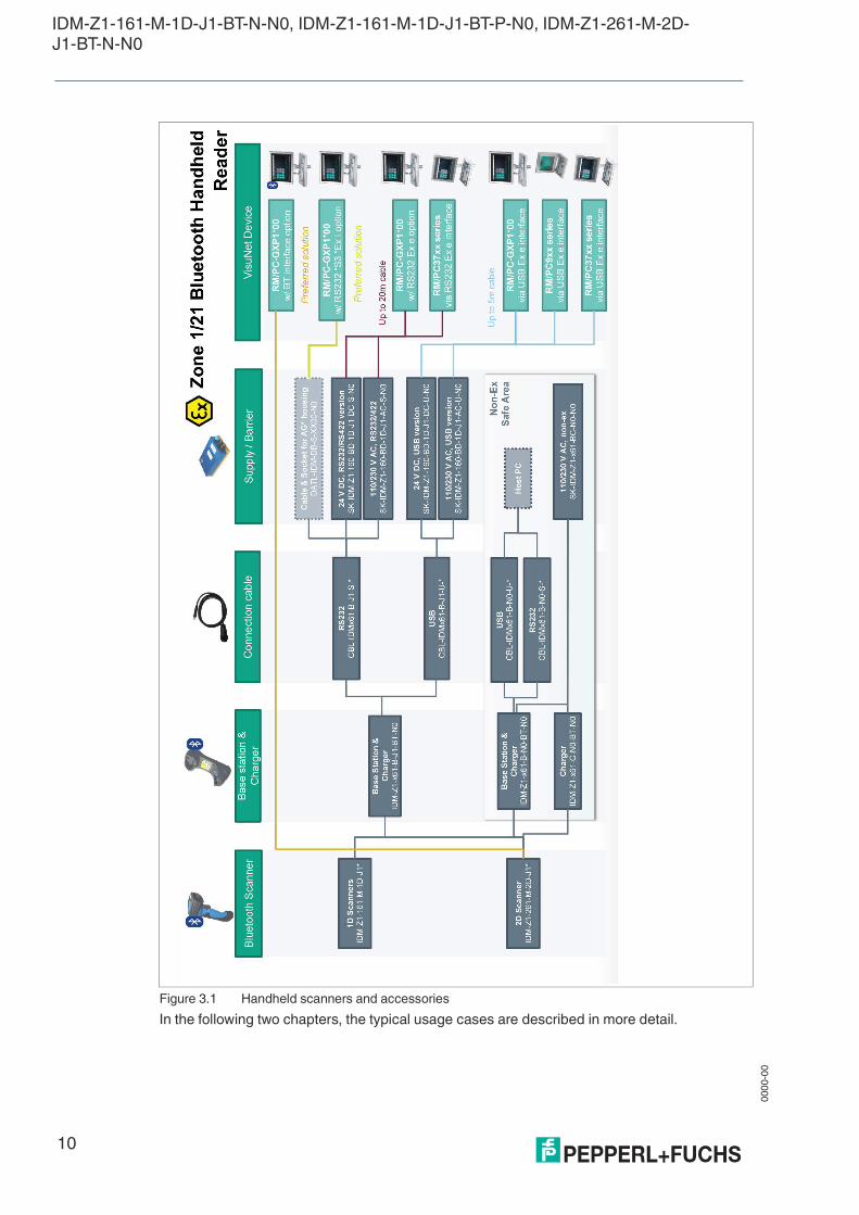
The Bluetooth handheld scanners and their accessories are presented in the following over-view. Charging the handheld scanner batteries can take place within the hazardous area using the Zone 1/21 certified base station and the associated power module. Furthermore, the scan-ner can be charged in the safe area using a base station/charging cradle.
00
00
-00
10
IDM-Z1-161-M-1D-J1-BT-N-N0, IDM-Z1-161-M-1D-J1-BT-P-N0, IDM-Z1-261-M-2D-J1-BT-N-N0
Figure 3.1 Handheld scanners and accessories
In the following two chapters, the typical usage cases are described in more detail.
IDM-Z1-161-M-1D-J1-BT-N-N0, IDM-Z1-161-M-1D-J1-BT-P-N0, IDM-Z1-261-M-2D-J1-BT-N-N0
00
00
-00
11
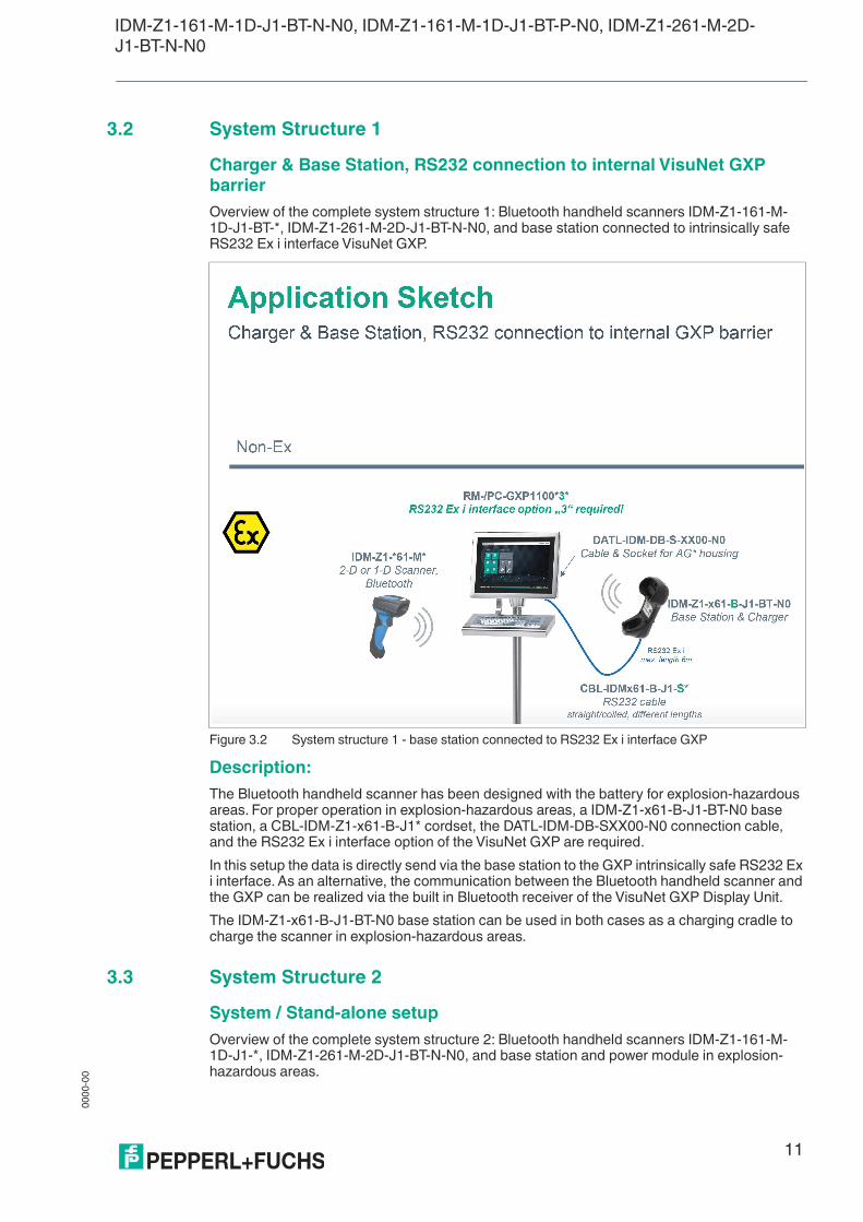
3.2 System Structure 1
Charger & Base Station, RS232 connection to internal VisuNet GXP barrier
Overview of the complete system structure 1: Bluetooth handheld scanners IDM-Z1-161-M-1D-J1-BT-*, IDM-Z1-261-M-2D-J1-BT-N-N0, and base station connected to intrinsically safe RS232 Ex i interface VisuNet GXP.
Figure 3.2 System structure 1 - base station connected to RS232 Ex i interface GXP
Description:
The Bluetooth handheld scanner has been designed with the battery for explosion-hazardous areas. For proper operation in explosion-hazardous areas, a IDM-Z1-x61-B-J1-BT-N0 base station, a CBL-IDM-Z1-x61-B-J1* cordset, the DATL-IDM-DB-SXX00-N0 connection cable, and the RS232 Ex i interface option of the VisuNet GXP are required.
In this setup the data is directly send via the base station to the GXP intrinsically safe RS232 Ex i interface. As an alternative, the communication between the Bluetooth handheld scanner and the GXP can be realized via the built in Bluetooth receiver of the VisuNet GXP Display Unit.
The IDM-Z1-x61-B-J1-BT-N0 base station can be used in both cases as a charging cradle to charge the scanner in explosion-hazardous areas.
3.3 System Structure 2
System / Stand-alone setup
Overview of the complete system structure 2: Bluetooth handheld scanners IDM-Z1-161-M-1D-J1-*, IDM-Z1-261-M-2D-J1-BT-N-N0, and base station and power module in explosion-hazardous areas.

00
00
-00
12
IDM-Z1-161-M-1D-J1-BT-N-N0, IDM-Z1-161-M-1D-J1-BT-P-N0, IDM-Z1-261-M-2D-J1-BT-N-N0
Figure 3.3 System structure 2 – scanner with base station connected to VisuNet GXP (Option 1)
Description:
The Bluetooth handheld scanner has been designed with the battery for explosion- hazardous areas. For proper operation in explosion-hazardous areas an IDM-Z1-x61- B-J1-BT-N0 base station, a CBL-IDM-Z1-x61-B-J1* cordset between the base station and the SK-IDM-Z1-160-BD-1D-J1* supply module, and a connection cable to the power supply are required.
Data can be transferred directly using an HMI system with Bluetooth interface (e.g., VisuNet GXP) (option 1) or using the base station, which can be connected to a host PC via the power supply module and a data line (option 2).
In the case of option 1, the IDM-Z1-x61-B-J1-BT-N0 base station can be used purely as a charging cradle. A data line to a host PC is not needed in this case.

IDM-Z1-161-M-1D-J1-BT-N-N0, IDM-Z1-161-M-1D-J1-BT-P-N0, IDM-Z1-261-M-2D-J1-BT-N-N0
00
00
-00
13
Figure 3.4 System structure 2 – scanner with base station connected to barrier (Option 2)
3.4 System Structure 3
VisuNet GXP Bluetooth option / Charger in safe area
Overview of the complete system structure 3: Bluetooth handheld scanner and charging cradle in non-explosion-hazardous areas
Note
The Supply module is available for RS232 and USB, make sure to use the compatible RS232 or USB cables.
00
00
-00
14
IDM-Z1-161-M-1D-J1-BT-N-N0, IDM-Z1-161-M-1D-J1-BT-P-N0, IDM-Z1-261-M-2D-J1-BT-N-N0
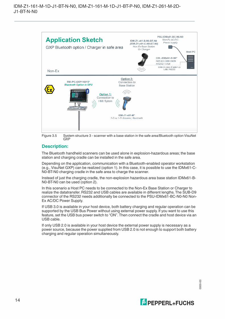
Figure 3.5 System structure 3 - scanner with a base station in the safe area/Bluetooth option VisuNet GXP
Description:
The Bluetooth handheld scanners can be used alone in explosion-hazardous areas; the base station and charging cradle can be installed in the safe area.
Depending on the application, communication with a Bluetooth-enabled operator workstation (e.g., VisuNet GXP) can be realized (option 1). In this case, it is possible to use the IDMx61-C-N0-BT-N0 charging cradle in the safe area to charge the scanner.
Instead of just the charging cradle, the non-explosion hazardous area base station IDMx61-B-N0-BT-N0 can be used (option 2).
In this scenario a Host PC needs to be connected to the Non-Ex Base Station or Charger to realize the datatransfer. RS232 and USB cables are available in different lengths. The SUB-D9 connector of the RS232 needs additionally be connected to the PSU-IDMx61-BC-N0-N0 Non-Ex AC/DC Power Supply.
If USB 3.0 is available in your host device, both battery charging and regular operation can be supported by the USB Bus Power without using external power supply. If you want to use this feature, set the USB bus power switch to “ON”. Then connect the cradle and host device via an USB cable.
If only USB 2.0 is available in your host device the external power supply is necessary as a power source, because the power supplied from USB 2.0 is not enough to support both battery charging and regular operation simultaneously.
IDM-Z1-161-M-1D-J1-BT-N-N0, IDM-Z1-161-M-1D-J1-BT-P-N0, IDM-Z1-261-M-2D-J1-BT-N-N0
00
00
-00
15
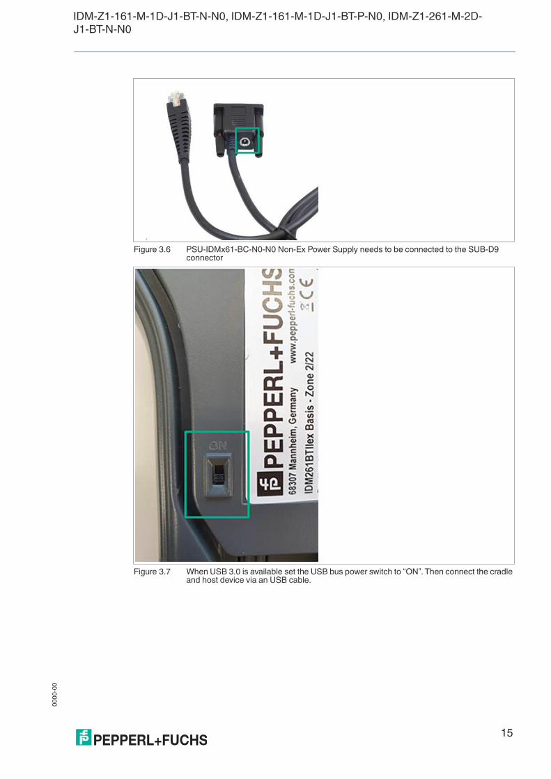
Figure 3.6 PSU-IDMx61-BC-N0-N0 Non-Ex Power Supply needs to be connected to the SUB-D9 connector
Figure 3.7 When USB 3.0 is available set the USB bus power switch to “ON”. Then connect the cradle and host device via an USB cable.
00
00
-00
16
IDM-Z1-161-M-1D-J1-BT-N-N0, IDM-Z1-161-M-1D-J1-BT-P-N0, IDM-Z1-261-M-2D-J1-BT-N-N0
4 Commissioning
4.1 Preparing Bluetooth Handheld Scanners
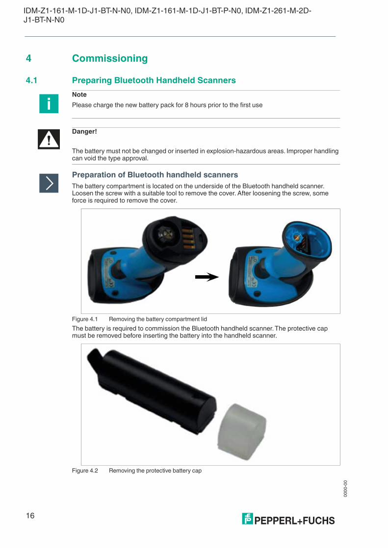
Preparation of Bluetooth handheld scanners
The battery compartment is located on the underside of the Bluetooth handheld scanner. Loosen the screw with a suitable tool to remove the cover. After loosening the screw, some force is required to remove the cover.
Figure 4.1 Removing the battery compartment lid
The battery is required to commission the Bluetooth handheld scanner. The protective cap must be removed before inserting the battery into the handheld scanner.
Figure 4.2 Removing the protective battery cap
Note
Please charge the new battery pack for 8 hours prior to the first use
Danger!
The battery must not be changed or inserted in explosion-hazardous areas. Improper handling can void the type approval.
IDM-Z1-161-M-1D-J1-BT-N-N0, IDM-Z1-161-M-1D-J1-BT-P-N0, IDM-Z1-261-M-2D-J1-BT-N-N0
00
00
-00
17
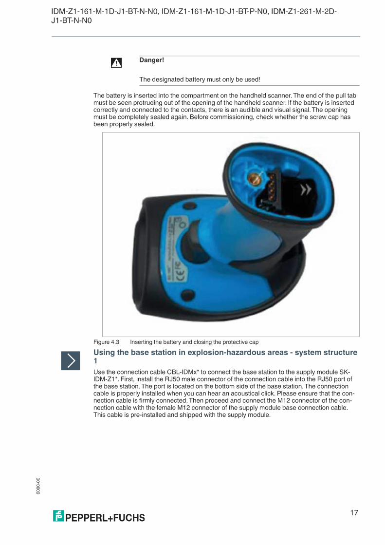
The battery is inserted into the compartment on the handheld scanner. The end of the pull tab must be seen protruding out of the opening of the handheld scanner. If the battery is inserted correctly and connected to the contacts, there is an audible and visual signal. The opening must be completely sealed again. Before commissioning, check whether the screw cap has been properly sealed.
Figure 4.3 Inserting the battery and closing the protective cap
Using the base station in explosion-hazardous areas - system structure 1
Use the connection cable CBL-IDMx* to connect the base station to the supply module SK-IDM-Z1*. First, install the RJ50 male connector of the connection cable into the RJ50 port of the base station. The port is located on the bottom side of the base station. The connection cable is properly installed when you can hear an acoustical click. Please ensure that the con-nection cable is firmly connected. Then proceed and connect the M12 connector of the con-nection cable with the female M12 connector of the supply module base connection cable. This cable is pre-installed and shipped with the supply module.
Danger!
The designated battery must only be used!

00
00
-00
18
IDM-Z1-161-M-1D-J1-BT-N-N0, IDM-Z1-161-M-1D-J1-BT-P-N0, IDM-Z1-261-M-2D-J1-BT-N-N0
Figure 4.4 Connecting RJ50 connector of connection cable CBL-IDM* to base station
Figure 4.5 Male M12 connector of connection cable CBL-IDM*
Figure 4.6 Female M12 connector of pre-installed base connection cable of the supply module SK-IDM-Z1*

IDM-Z1-161-M-1D-J1-BT-N-N0, IDM-Z1-161-M-1D-J1-BT-P-N0, IDM-Z1-261-M-2D-J1-BT-N-N0
00
00
-00
19
Figure 4.7 Connecting the plug coupling to the supply module basic connection line
The handheld scanner is placed in the charger. The underside of the handle is used first to ensure that the charging contacts are properly connected. The LED light on the scanner head indicates successful charging.
Figure 4.8 Inserting the scanner into the base station
Using the base station in non-explosion hazardous areas - system structure 2
With a non-explosion-protected base station, charging in non-explosion hazardous areas can be performed using the PSU-IDMx61-BC-N0-N0 power supply. The cable is plugged into the opening for this at the bottom of the base station. For a base station for explosion-hazardous areas, this connection is sealed at the factory.
00
00
-00
20
IDM-Z1-161-M-1D-J1-BT-N-N0, IDM-Z1-161-M-1D-J1-BT-P-N0, IDM-Z1-261-M-2D-J1-BT-N-N0
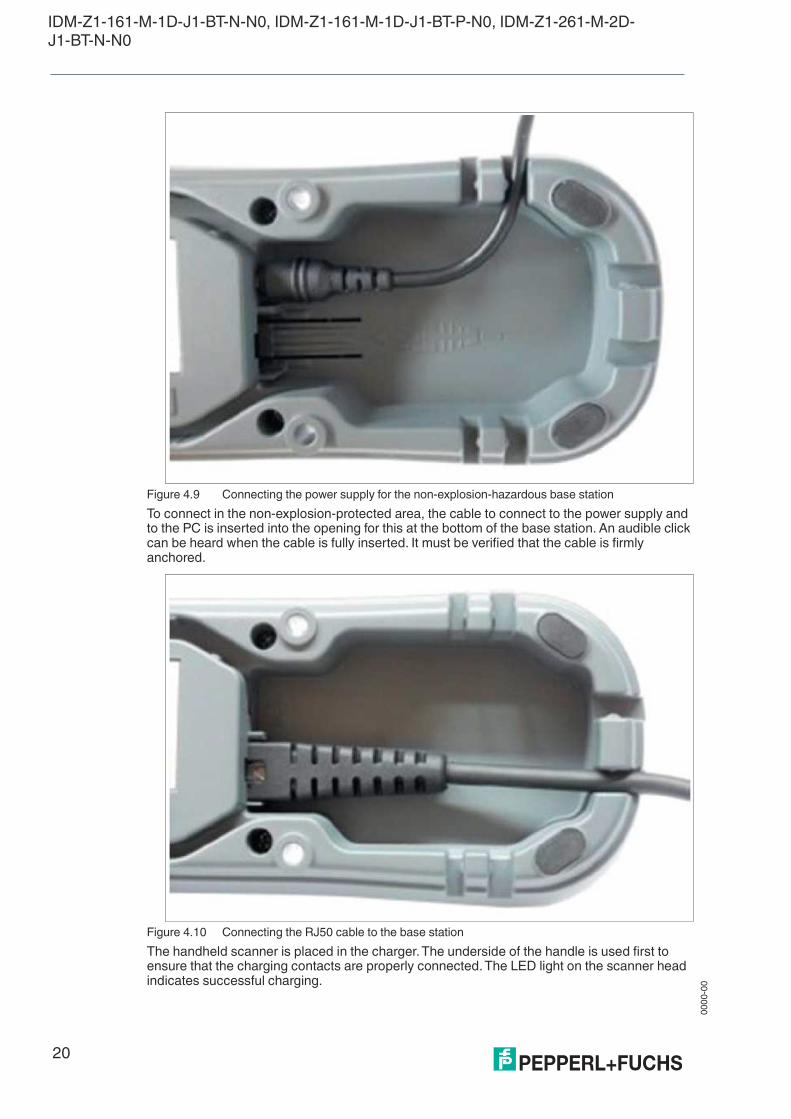
Figure 4.9 Connecting the power supply for the non-explosion-hazardous base station
To connect in the non-explosion-protected area, the cable to connect to the power supply and to the PC is inserted into the opening for this at the bottom of the base station. An audible click can be heard when the cable is fully inserted. It must be verified that the cable is firmly anchored.
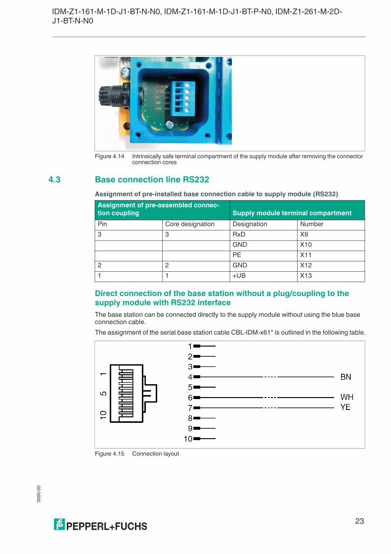
Figure 4.10 Connecting the RJ50 cable to the base station
The handheld scanner is placed in the charger. The underside of the handle is used first to ensure that the charging contacts are properly connected. The LED light on the scanner head indicates successful charging.

IDM-Z1-161-M-1D-J1-BT-N-N0, IDM-Z1-161-M-1D-J1-BT-P-N0, IDM-Z1-261-M-2D-J1-BT-N-N0
00
00
-00
21
Figure 4.11 Inserting the scanner into the base station
4.2 Pinout of Supply Module with RS232 or USB
Supplying the base station according to system structure 2 via connector - plug/coupling.
The terminal assignment is located under the unscrewable opening on the front of the supply module.
Changes to the pinout may only be carried out by trained and qualified personnel.
Connection of the base station to the supply module RS232 or USB via connector - plug/coupling
The terminal assignment is located under the unscrewable opening on the front of the supply module.
(1) Ex e terminal compartment to connect the power supply and the data line
(2) Ex i terminal compartment to connect the consumers (base station/scanner)
Danger!
Do not open the housing in the explosion-hazardous area
Before the device is put into operation in explosion-hazardous areas, it must be ensured that the housing is completely closed again and screwed on properly.

00
00
-00
22
IDM-Z1-161-M-1D-J1-BT-N-N0, IDM-Z1-161-M-1D-J1-BT-P-N0, IDM-Z1-261-M-2D-J1-BT-N-N0
Figure 4.12 Supply module terminal compartment
External connection lines:
The Bluetooth handheld scanner, the base station, and the supply module may be connected and used in explosion-hazardous areas. The current rating of the connection line must be observed.
The blue base connection cable is delivered pre-assembled with the supply module SK-IDM-Z1-*. The cable consists of a M12 connector plug and a 3-core cable. The individual cores are numbered (printed on the core insulation) and must be connected as follows (4.2 RS232 inter-face and 4.3 USB interface) to the intrinsically safe terminals of the supply module.
Figure 4.13 Terminal blocks in the terminal compartment
Data lines USB: 0.2 – 2.5 mm2, 4-core or
RS232: 0.2 – 2.5 mm2 3-core
Supply line 0.2 – 2.5 mm2 3-wire
(see accessories in the appendix)
IDM-Z1-161-M-1D-J1-BT-N-N0, IDM-Z1-161-M-1D-J1-BT-P-N0, IDM-Z1-261-M-2D-J1-BT-N-N0
00
00
-00
23
Figure 4.14 Intrinsically safe terminal compartment of the supply module after removing the connector connection cores
4.3 Base connection line RS232
Assignment of pre-installed base connection cable to supply module (RS232)
Direct connection of the base station without a plug/coupling to the supply module with RS232 interface
The base station can be connected directly to the supply module without using the blue base connection cable.
The assignment of the serial base station cable CBL-IDM-x61* is outlined in the following table.
Figure 4.15 Connection layout
Assignment of pre-assembled connec-
tion coupling Supply module terminal compartment
Pin Core designation Designation Number
3 3 RxD X9
GND X10
PE X11
2 2 GND X12
1 1 +UB X13

00
00
-00
24
IDM-Z1-161-M-1D-J1-BT-N-N0, IDM-Z1-161-M-1D-J1-BT-P-N0, IDM-Z1-261-M-2D-J1-BT-N-N0
Assignment of connection cable CBL-IDM-x61* to supply module (RS232)
4.4 Base connection line USB
Base connection cable USB
Connection of USB connection cable to supply module
Cordset assignment Supply module terminal compartment
RJ50 pinout Strand color Designation Assignment
6 White TxD X9
X10
X11
4 Brown GND X12
7 Yellow +UB X13
Note
Information relating to programming from the SICK AG manual (www.SICK.com) is required for the complete commissioning of the handheld scanner.
Pinout of connector plug
Pin Designation
3 D+
2 D-
4 GND
1 +UB
Pre-assembled connection coupling Terminal compartment
Pin Core Designation Number
3 3 D+ X9
2 4 D- X10
PE X11
4 2 GND X12
1 1 +UB X13

IDM-Z1-161-M-1D-J1-BT-N-N0, IDM-Z1-161-M-1D-J1-BT-P-N0, IDM-Z1-261-M-2D-J1-BT-N-N0
00
00
-00
25
Direct connection of the base station without plug/coupling to the supply module with USB interface
Figure 4.16 RJ50 plug - connection layout
Base station cordset
Cordset assignment Supply module terminal compartment
RJ45 pinout Strand color Designation Assignment
2 Green D+2SL X9
10 White D-2SL X10
X11
4 Black GND X12
7 Brown +UB X13
Note
Information relating to programming from the SICK AG manual (www.SICK.com) is required for the complete commissioning of the handheld scanner.
00
00
-00
26
IDM-Z1-161-M-1D-J1-BT-N-N0, IDM-Z1-161-M-1D-J1-BT-P-N0, IDM-Z1-261-M-2D-J1-BT-N-N0
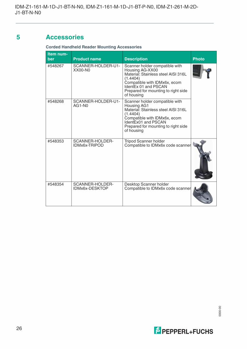
5 Accessories
Corded Handheld Reader Mounting Accessories
Item num-
ber Product name Description Photo
#548267 SCANNER-HOLDER-U1-XX00-N0
Scanner holder compatible with Housing AG-XX00Material: Stainless steel AISI 316L (1.4404)Compatible with IDMx6x, ecom IdentEx 01 and PSCANPrepared for mounting to right side of housing
#548268 SCANNER-HOLDER-U1-AG1-N0
Scanner holder compatible with Housing AG1Material: Stainless steel AISI 316L (1.4404)Compatible with IDMx6x, ecom IdentEx01 and PSCANPrepared for mounting to right side of housing
#548353 SCANNER-HOLDER-IDMx6x-TRIPOD
Tripod Scanner holderCompatible to IDMx6x code scanner
#548354 SCANNER-HOLDER-IDMx6x-DESKTOP
Desktop Scanner holderCompatible to IDMx6x code scanner
IDM-Z1-161-M-1D-J1-BT-N-N0, IDM-Z1-161-M-1D-J1-BT-P-N0, IDM-Z1-261-M-2D-J1-BT-N-N0
00
00
-00
27
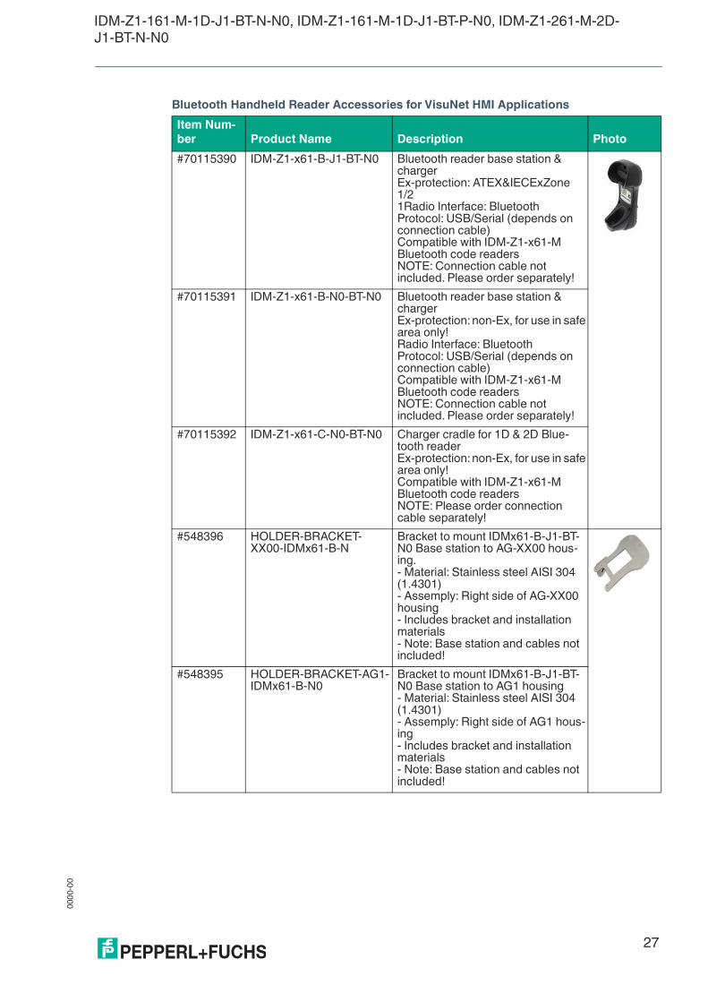
Bluetooth Handheld Reader Accessories for VisuNet HMI Applications
Item Num-
ber Product Name Description Photo
#70115390 IDM-Z1-x61-B-J1-BT-N0 Bluetooth reader base station & chargerEx-protection: ATEX&IECExZone 1/21Radio Interface: BluetoothProtocol: USB/Serial (depends on connection cable)Compatible with IDM-Z1-x61-M Bluetooth code readersNOTE: Connection cable not included. Please order separately!
#70115391 IDM-Z1-x61-B-N0-BT-N0 Bluetooth reader base station & chargerEx-protection: non-Ex, for use in safe area only!Radio Interface: BluetoothProtocol: USB/Serial (depends on connection cable)Compatible with IDM-Z1-x61-M Bluetooth code readersNOTE: Connection cable not included. Please order separately!
#70115392 IDM-Z1-x61-C-N0-BT-N0 Charger cradle for 1D & 2D Blue-tooth readerEx-protection: non-Ex, for use in safe area only!Compatible with IDM-Z1-x61-M Bluetooth code readersNOTE: Please order connection cable separately!
#548396 HOLDER-BRACKET-XX00-IDMx61-B-N
Bracket to mount IDMx61-B-J1-BT-N0 Base station to AG-XX00 hous-ing.- Material: Stainless steel AISI 304 (1.4301)- Assemply: Right side of AG-XX00 housing- Includes bracket and installation materials- Note: Base station and cables not included!
#548395 HOLDER-BRACKET-AG1-IDMx61-B-N0
Bracket to mount IDMx61-B-J1-BT-N0 Base station to AG1 housing- Material: Stainless steel AISI 304 (1.4301)- Assemply: Right side of AG1 hous-ing- Includes bracket and installation materials- Note: Base station and cables not included!
00
00
-00
28
IDM-Z1-161-M-1D-J1-BT-N-N0, IDM-Z1-161-M-1D-J1-BT-P-N0, IDM-Z1-261-M-2D-J1-BT-N-N0
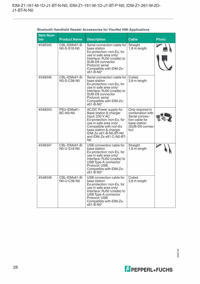
Bluetooth Handheld Reader Accessories for VisuNet HMI Applications
Item Num-
ber Product Name Description Cable Photo
#548345 CBL-IDMx61-B-N0-S-S18-N0
Serial connection cable for base stationEx-protection: non-Ex, for use in safe area only!Interface: RJ50 (cradle) to SUB-D9 connectorProtocol: serialCompatible with IDM-Zx-x61-B-N0*
Straight1,8 m length
#548346 CBL-IDMx61-B-N0-S-C38-N0
Serial connection cable for base stationEx-protection: non-Ex, for use in safe area only!Interface: RJ50 (cradle) to SUB-D9 connectorProtocol: serialCompatible with IDM-Zx-x61-B-N0*
Coiled3,8 m length
#548343 PSU-IDMx61-BC-N0-N0
AC/DC Power supply for Base station & chargerInput: 230 V ACEx-protection: non-Ex, for use in safe area only!Compatible with non-Ex base station & chargerIDM-Zx-x61-B-N0-BT-N0 and IDM-Zx-x61-C-N0-BT-N0
Only required in combination with Serial connec-tion cable for base station (SUB-D9 connec-tor)
#548347 CBL-IDMx61-B-N0-U-S18-N0
USB connection cable for base stationEx-protection: non-Ex, for use in safe area only!Interface: RJ50 (cradle) to USB Type A connectorProtocol: USBCompatible with IDM-Zx-x61-B-N0*
Straight1,8 m length
#548348 CBL-IDMx61-B-N0-U-C38-N0
USB connection cable for base stationEx-protection: non-Ex, for use in safe area only!Interface: RJ50 (cradle) to USB Type A connectorProtocol: USBCompatible with IDM-Zx-x61-B-N0*
Coiled3,8 m length

IDM-Z1-161-M-1D-J1-BT-N-N0, IDM-Z1-161-M-1D-J1-BT-P-N0, IDM-Z1-261-M-2D-J1-BT-N-N0
00
00
-00
29
#548349 CBL-IDMx61-B-J1-S-S18-N0
Serial connection cable for base stationEx-protection: suitable for Zone 1/21 & Zone 2/22Interface: RJ50 (cradle) to M12 male connectorCable: straight; 1,8m lengthProtocol: serialCompatible with IDM-Zx-x61-B-J1* base station
Straight1,8 m length
#548350 CBL-IDMx61-B-J1-S-C38-N0
Serial connection cable for base stationEx-protection: suitable for Zone 1/21 & Zone 2/22Interface: RJ50 (cradle) to M12 male connectorCable: coiled; 3,8m lengthProtocol: serialCompatible with IDM-Zx-x61-B-J1* base station
Coiled3,8 m length
#548351 CBL-IDMx61-B-J1-U-S18-N0
USB connection cable for base stationEx-protection: suitable for Zone 1/21 & Zone 2/22Interface: RJ50 (cradle) to M12 male connectorCable: straight; 1,8m lengthProtocol: USBCompatible with IDM-Zx-x61-B-J1* base station
Straight1,8 m length
#548352 CBL-IDMx61-B-J1-U-C38-N0
USBconnection cable for base stationEx-protection: suitable for Zone 1/21 & Zone 2/22Interface: RJ50 (cradle) to M12 male connectorCable: coiled; 3,8m lengthProtocol: USBCompatible with IDM-Zx-x61-B-J1* base station
Coiled3,8 m length
#548376 DATL-IDM-DB-S-XX00-N0
Connector cable for wired 1D Scanner IDM-Z1-160-D-1D-J1-S-* (S3-Interface required) and 2D Scanner IDM-Z2-260-D-2D-J1-S* (S4-interface required) compatible with Housing AG-XX00-* and AG1- 4-wire with ferrules- IDM Scanner connection via M12-connector- Note: Supports only RS232 Scanner/Basesta-tion
1,0 m length
Item Num-
ber Product Name Description Cable Photo

00
00
-00
30
IDM-Z1-161-M-1D-J1-BT-N-N0, IDM-Z1-161-M-1D-J1-BT-P-N0, IDM-Z1-261-M-2D-J1-BT-N-N0
Serial extension cables
Cable accessories
Item Num-
ber Product Name Description Cable Photo
#548356 CBL-IDMx6x-DB-J1-S-C30-N0
Serial extension cableEx-protection: suitable for Zone 1/21 & Zone 2/22Interface: M12 female socket to M12 malecon-nectorProtocol: serial
Coiled3 m length
#548357 CBL-IDMx6x-DB-J1-S-C60-N0
Serial extension cableEx-protection: suitable for Zone 1/21 & Zone 2/22Interface: M12 female socket to M12 male con-nectorProtocol: serial
Coiled6 m length
#548365 CBL-IDMx6x-DB-J1-S-S30-N0
Serial extension cableEx-protection: suitable for Zone 1/21 & Zone 2/22Interface: M12 female socket to M12 malecon-nectorProtocol: serial
Straight3 m length
#548355 CBL-IDMx6x-DB-J1-S-S60-N0
Serial extension cableEx-protection: suitable for Zone 1/21 & Zone 2/22Interface: M12 female socket to M12 male con-nector Protocol: serial
Straight6 m length
Item Num-
ber Product Name Description Cable
#548379 S-RN2/DB9-5-N0 RS232 cable with SUB-D9 plug (female) and open cable ends with wire end fer-rules
5 m length
#548380 S-RN2/DB9-20-N0 RS232 cable with SUB-D9 plug (female) and open cable ends with wire end fer-rules
20 m length
#193077 DATL-A3-1.5-1 Supply line for 90 – 240 VAC supply 3 x 1.5 mm², diameter 8.1 mmAssembly 6 x 1.5 mm² wire end ferrules
IDM-Z1-161-M-1D-J1-BT-N-N0, IDM-Z1-161-M-1D-J1-BT-P-N0, IDM-Z1-261-M-2D-J1-BT-N-N0
00
00
-00
31
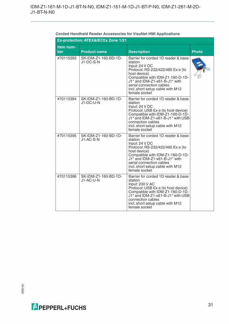
Corded Handheld Reader Accessories for VisuNet HMI Applications
Ex-protection: ATEX&IECEx Zone 1/21
Item num-
ber Product name Description Photo
#70115393 SK-IDM-Z1-160-BD-1D-J1-DC-S-N
Barrier for corded 1D reader & base stationInput: 24 V DCProtocol: RS-232/422/485 Ex e (to host device)Compatible with IDM-Z1-160-D-1D-J1* and IDM-Z1-x61-B-J1* with serial connection cablesincl. short setup cable with M12 female socket
#70115394 SK-IDM-Z1-160-BD-1D-J1-DC-U-N
Barrier for corded 1D reader & base stationInput: 24 V DCProtocol: USB Ex e (to host device) Compatible with IDM-Z1-160-D-1D-J1* and IDM-Z1-x61-B-J1* with USB connection cablesincl. short setup cable with M12 female socket
#70115395 SK-IDM-Z1-160-BD-1D-J1-AC-S-N
Barrier for corded 1D reader & base stationInput: 24 V DCProtocol: RS-232/422/485 Ex e (to host device)Compatible with IDM-Z1-160-D-1D-J1* and IDM-Z1-x61-B-J1* with serial connection cablesincl. short setup cable with M12 female socket
#70115396 SK-IDM-Z1-160-BD-1D-J1-AC-U-N
Barrier for corded 1D reader & base stationInput: 230 V ACProtocol: USB Ex e (to host device)Compatible with IDM-Z1-160-D-1D-J1* and IDM-Z1-x61-B-J1* with USB connection cablesincl. short setup cable with M12 female socket

Pepperl+Fuchs Quality
Download our latest policy here:
www.pepperl-fuchs.com/quality
www.pepperl-fuchs.com
© Pepperl+Fuchs · Subject to modifications
Printed in Germany / DOCT-6088A
Related Documents