Draft Document i RESEARCH INFORMATION LETTER 1002: Identification of Failure Modes in Digital Safety Systems – Expert Clinic Findings, Part 2 EXECUTIVE SUMMARY This research information letter (RIL) reports the progress made with respect to identifying failure modes for use in assurance of a Digital Instrumentation and Controls (DI&C) safety system. The work was performed per Commission direction as stated in Staff Requirements Memorandum (SRM) M0806058B. In this report, “failure” is defined as the termination of the ability of an item to perform a required function. The term “failure mode” is used in the context of an overall DI&C system to describe how a failure is observed to occur. Results were obtained by surveying existing knowledge from a diverse panel of safety critical digital system experts consulted by the Nuclear Regulatory Commission (NRC) during an expert elicitation process conducted in 2010 and through supplemental research that included a review of over 150 public and non-public documents and additional interviews with experts not part of the elicitation process. Findings are summarized and synthesized in ten sets of “generic” digital system failure modes for each function of the system. Furthermore, in addition to “generic” failure modes, findings indicate that there may be additional system-specific failure modes. Research on this topic is continuing in several places. Completeness (of a set of failure modes) is not assurable at this time. Alternative analytical approaches are being investigated to support needs for safety assurance. The report also includes results from staff investigations on the efficacy of Software Fault Modes and Effects Analysis (SFMEA) as a method for identifying faults leading to system failures impairing a safety function. Whereas the term “failure mode” is used in the context of an overall DI&C system, the corresponding concept for a software item is “fault mode.” Software used in digital safety systems is complex logic. The ability of software in DI&C safety systems to perform a required function does not terminate due to wear and tear. The term “failure” (in the meaning stated above) does not apply to software in DI&C safety systems. A “fault” is defined as the state of an item characterized by the inability to perform a required function, excluding the inability during preventive maintenance or other planned actions, or due to lack of external resources. The term “fault mode” is defined as one of the possible states of a faulty item for a required function. Completeness (of a set of faults and fault modes) is not assurable at this time. Six distinct SFMEA methods were found, but the staff did not find a sound technical basis to require NRC applicants and licensees to perform an SFMEA similar to any of these methods. NUREG/IA-0254, Suitability of Fault Modes and Effects Analysis for Regulatory Assurance of Complex Logic in Digital Instrumentation and Control Systems provides additional information supporting this conclusion. Results and conclusions presented in this RIL concern assurance of digital safety systems. The results and conclusions are not intended to address issues related to quantifying the reliability of digital systems. As such, results and conclusions about DI&C failure modes and software fault modes discussed in this RIL may not be applicable to NRC research on the development of probabilistic models for DI&C systems for inclusion in Nuclear Power Plant (NPP) Probabilistic Risk Assessments (PRAs).

Welcome message from author
This document is posted to help you gain knowledge. Please leave a comment to let me know what you think about it! Share it to your friends and learn new things together.
Transcript

Draft Document
i
RESEARCH INFORMATION LETTER 1002:
Identification of Failure Modes in Digital Safety Systems – Expert Clinic Findings,
Part 2
EXECUTIVE SUMMARY
This research information letter (RIL) reports the progress made with respect to identifying failure modes for use in assurance of a Digital Instrumentation and Controls (DI&C) safety system. The work was performed per Commission direction as stated in Staff Requirements Memorandum (SRM) M0806058B. In this report, “failure” is defined as the termination of the ability of an item to perform a required function. The term “failure mode” is used in the context of an overall DI&C system to describe how a failure is observed to occur. Results were obtained by surveying existing knowledge from a diverse panel of safety critical digital system experts consulted by the Nuclear Regulatory Commission (NRC) during an expert elicitation process conducted in 2010 and through supplemental research that included a review of over 150 public and non-public documents and additional interviews with experts not part of the elicitation process. Findings are summarized and synthesized in ten sets of “generic” digital system failure modes for each function of the system. Furthermore, in addition to “generic” failure modes, findings indicate that there may be additional system-specific failure modes. Research on this topic is continuing in several places. Completeness (of a set of failure modes) is not assurable at this time. Alternative analytical approaches are being investigated to support needs for safety assurance.
The report also includes results from staff investigations on the efficacy of Software Fault Modes and Effects Analysis (SFMEA) as a method for identifying faults leading to system failures impairing a safety function. Whereas the term “failure mode” is used in the context of an overall DI&C system, the corresponding concept for a software item is “fault mode.” Software used in digital safety systems is complex logic. The ability of software in DI&C safety systems to perform a required function does not terminate due to wear and tear. The term “failure” (in the meaning stated above) does not apply to software in DI&C safety systems. A “fault” is defined as the state of an item characterized by the inability to perform a required function, excluding the inability during preventive maintenance or other planned actions, or due to lack of external resources. The term “fault mode” is defined as one of the possible states of a faulty item for a required function. Completeness (of a set of faults and fault modes) is not assurable at this time. Six distinct SFMEA methods were found, but the staff did not find a sound technical basis to require NRC applicants and licensees to perform an SFMEA similar to any of these methods. NUREG/IA-0254, Suitability of Fault Modes and Effects Analysis for Regulatory Assurance of Complex Logic in Digital Instrumentation and Control Systems provides additional information supporting this conclusion.
Results and conclusions presented in this RIL concern assurance of digital safety systems. The results and conclusions are not intended to address issues related to quantifying the reliability of digital systems. As such, results and conclusions about DI&C failure modes and software fault modes discussed in this RIL may not be applicable to NRC research on the development of probabilistic models for DI&C systems for inclusion in Nuclear Power Plant (NPP) Probabilistic Risk Assessments (PRAs).

Draft Document
ii
TABLE OF CONTENTS
Section Page EXECUTIVE SUMMARY ............................................................................................................... i
1. INTRODUCTION ............................................................................................................... 1 1.1. Intended Audience and Prerequisite Knowledge................................................... 1 1.2. Objectives .............................................................................................................. 1 1.3. Scope .................................................................................................................... 3
2. ORGANIZATION OF REMAINING SECTIONS ................................................................ 4
3. BACKGROUND ................................................................................................................ 5
4. RESEARCH METHOD ...................................................................................................... 7 4.1. NRC Expert Elicitation Activities ............................................................................ 7 4.2. Supplemental NRC Research Activities ................................................................ 7
5. FINDINGS ......................................................................................................................... 8 5.1. Identified Digital System Failure Modes ................................................................ 8 5.2. Efficacy of SFMEA for Identifying Faults Leading to System Failures ................. 23
6. REGULATORY CONSIDERATIONS .............................................................................. 24 6.1. Direct References to Failure Mode Identification and Analysis in NRC
Regulations ......................................................................................................... 24 6.2. Failure Mode Identification and Analysis and the Single Failure Criterion for
Protection and Safety Systems ........................................................................... 24 6.3. Failure Mode Identification and Analysis Endorsed in Regulatory Guidance ...... 25 6.4. NRC Staff Reviews of Failure Modes and Failure Mode Analyses ..................... 25 6.5. Requirement in IEEE Std 603-1991 Clause 4 ..................................................... 26
7. SUMMARY AND CONCLUSIONS .................................................................................. 27 7.1. Objective 1 .......................................................................................................... 27 7.2. Objective 2 .......................................................................................................... 27
8. NEXT STEPS .................................................................................................................. 28
9. GLOSSARY .................................................................................................................... 29 9.1. Selection of Definitions ........................................................................................ 29 9.2. Definitions ............................................................................................................ 29
10. EXPERTS CONSULTED ................................................................................................ 34
11. CITED LITERATURE ...................................................................................................... 36
12. LITERATURE REVIEWED BUT NOT CITED ................................................................. 41
APPENDIX A. THE VOCABULARY RELATED TO FAILURE MODES – A DISCUSSION A-1 A.1. Failure ............................................................................................................... A-1 A.2. Reason for Avoiding the Term “Failure” for Software ........................................ A-2 A.3. Fault .................................................................................................................. A-2
Draft Document
iii
A.4. Error .................................................................................................................. A-3 A.5. Stimulus-Response, Event-Action, State-Mode – Concepts to Characterize
Behavior ............................................................................................................ A-3 A.6. Failure Modes .................................................................................................... A-5 A.7. Fault Modes ....................................................................................................... A-6 A.8. Appendix A Bibliography ................................................................................... A-6
APPENDIX B. IDENTIFIED SOFTWARE FAULTS AND FAULT MODES SETS ......... B-1 B.1. Software Faults and Fault Modes Identified by Source ..................................... B-1 B.2. Fault Classification and Taxonomy Schemes.................................................. B-14 B.3. Summary of Software Faults and Fault Modes Found .................................... B-19 B.4. Bibliography ..................................................................................................... B-20
APPENDIX C. SOFTWARE FAULT MODES AND EFFECTS ANALYSIS METHODS .. C-23 C.1. SFMEA in Literature Reviewed ....................................................................... C-23 C.2. Efficacy of SFMEA in Identifying Faults........................................................... C-27 C.3. Bibliography ..................................................................................................... C-28
APPENDIX D. OPERATING EXPERIENCE AND FAILURE MODES .......................... D-1 D.1. Failure Modes of Induction Motors: Example usage ......................................... D-1 D.2. Digital System Failure Modes: Utility in organizing operating experience data . D-2 D.3. Bibliography ....................................................................................................... D-2
APPENDIX E. FAILURE MODE RELATED EFFORTS BY NRC PRA STAFF AND OTHER STAKEHOLDERS ........................................................................................... E-1 E.1. Probabilistic Risk Assessment Research .......................................................... E-1 E.2. Working Group on Risk Assessment (WGRisk) Activities and Results ............. E-2 E.3. Halden Research Project Efforts ....................................................................... E-2 E.4. References ........................................................................................................ E-3
LIST OF FIGURES
Figure Page Figure 1 Inter-related research work products ..................................................................... 5
LIST OF TABLES
Table Page Table 1 Failure Mode Set A - NRC/IRSN Collaboration [3] ................................................ 9 Table 2 Failure Mode Set B - Orthogonal defect classification [8]. ................................... 11 Table 3 Failure Mode Set C [19]. ..................................................................................... 12 Table 4 Failure Mode Set D [21]. ..................................................................................... 13 Table 5 Failure Mode Set E [22]. ...................................................................................... 14 Table 6 Failure Mode Set F .............................................................................................. 15 Table 7 Failure Mode Set G [24] ...................................................................................... 16 Table 8 Failure Mode Set H FMEA and systematic design [25]. .................................... 16 Table 9 Failure Mode Set I [26] ........................................................................................ 17 Table 10 Failure Mode Set J – WGRisk Activities [27] and [28]. ........................................ 17 Table 11 Summary of failure mode correlations to Failure Mode Set A ............................. 18

Draft Document
iv
Table 12 Characterization of failure modes of a “generic” digital safety system. ............... 21 Table 13 Experts interviewed During NRC’s DI&C Expert Elicitation Activity. ................... 34 Table 14 Experts Consulted During Additional NRC Research Activities. ......................... 35 Table B-1 Fault/Fault Mode Set 1 [3]. ................................................................................ B-2 Table B-2 Fault/Fault Mode Set 2 [4]. ................................................................................ B-3 Table B-3 Fault/Fault Mode Set 3 [5]. ................................................................................ B-4 Table B-4 Fault/Fault Mode Set 4 [6]. ................................................................................ B-4 Table B-5 Fault/Fault Mode Set 5 [8]. ................................................................................ B-5 Table B-6 Fault/Fault Mode Set 6 [9]. ................................................................................ B-7 Table B-7 Fault/Fault Mode Set 7 [10]. .............................................................................. B-9 Table B-8 Fault/Fault Mode Set 8 [11] ............................................................................... B-9 Table B-9 Fault/Fault Mode Set 9 [12]. ............................................................................ B-10 Table B-10 Fault/Fault Mode Set 10 [1]. ............................................................................ B-11 Table B-11 Defect Attributes in [1] ..................................................................................... B-15

Draft Document
1
1. INTRODUCTION
This Research Information Letter (RIL) is the second in a series of three letters (RIL-1001, RIL-1002, and RIL-1003) that collectively respond to the Digital Instrumentation and Control (DI&C) - relevant part of the Nuclear Regulatory Commission (NRC) Staff Requirements Memorandum (SRM) M080605B, “Meeting with Advisory Committee on Reactor Safeguards (ACRS),” dated June 26, 2008 [1]. RIL-1001, “Software-Related Uncertainties in the Assurance of Digital Safety Systems – Expert Clinic Findings, Part 1” was published on May 4, 2011 [2]. This RIL reports the progress made with respect to identifying failure modes for use in assurance of digital safety systems. Findings from staff investigations on the efficacy Software Fault Modes and Effects Analysis (SFMEA)1 for use in assurance of software are also included in this RIL. RIL-1003 will discuss the feasibility of applying failure mode analysis to quantification of risk associated with digital safety systems.
The insights described in this letter are interim results of ongoing research aiming to support improvement of regulatory guidance for the assurance of DI&C safety systems. The need for RIL-1002 arises because failure modes of digital systems are not well understood (i.e. digital systems have failed in unexpected ways), not seen in analog technology based systems.
1.1. Intended Audience and Prerequisite Knowledge
The intended audience is NRC staff performing licensing reviews of DI&C systems. It is assumed that readers are cognizant of the information presented in RIL-1001. Additionally, it is recommended that readers review the Glossary in Section 9 and Appendix A to become familiar with the terminology used in this report prior to a detailed review.
1.2. Objectives
The objectives of this RIL are to
1. Report the progress made with respect to identifying and analyzing digital I&C failure modes,” as required by SRM M080605B [1].
2. Report the findings resulting from the staff investigation on the efficacy of SFMEA as a method for identifying faults leading to system failures impairing a safety function conducted as part of the fiscal year (FY) 2010 – FY 2014 Digital Systems Research Plan.2 [4]
3. Formally transfer knowledge regarding these research results to licensing reviewers in
the Office of Nuclear Reactor Regulation (NRR) and the Office of New Reactors (NRO)
1 Whereas the term, “failure modes and effects analysis (FMEA)” is used in the context of the overall DI&C system, the corresponding concept for software (and other forms of complex logic) in a DI&C system is “fault modes and effects analysis.” Logic does not fail in the traditional sense of degradation of a hardware component but the system could fail, due to a pre-existing logic fault, triggered by some combination of inputs and system-internal conditions.” [3] (See Appendix A) 2 This objective satisfies the staff commitment detailed in NRC Staff Response Letter dated December 7, 2010, in response to ACRS recommendation #4 detailed in [4] (See Background)

Draft Document
2
4. Add to the basis established in RIL-1001 for research results to be reported in RIL-1003 “Feasibility of Applying Failure Mode Analysis to Quantification of Risk Associated with Digital Safety Systems – Expert Clinic Findings, Part 3.”

Draft Document
3
1.3. Scope
The scope of this document is bounded by Objective 1 in the context of assuring a digital safety system in a nuclear power plant (NPP). The results and conclusions are not intended to address issues related to quantifying the reliability of digital systems. As such, results and conclusions about DI&C failure modes and software fault modes discussed in this RIL may not be applicable to NRC research on the development of probabilistic models for DI&C systems for inclusion in Nuclear Power Plant (NPP) Probabilistic Risk Assessments (PRAs).
Related topics such as system hazard analysis, development assurance, defensive measures, preventative approaches, and hardware/software interactions are outside the scope of this RIL and are addressed or will be addressed through ongoing or future Office of Nuclear Regulatory Research (RES) efforts with input from the NRC licensing offices. The use of the failure modes reported in this RIL for purposes other than assurance of digital safety systems in the Nuclear Industry is also outside the scope of this work.

Draft Document
4
2. ORGANIZATION OF REMAINING SECTIONS
Section 3 summarizes the history that led to this RIL. Section 4 describes the research method. Section 5 presents the findings. Section 6 presents the regulatory significance of the lessons learned from the findings. Section 7 summarizes the conclusions. Section 8 presents the next steps. A glossary of terms used is presented in Section 9. Sections 10 through Section 12 list the experts consulted, literature cited, and literature reviewed but not cited during the research that led to this document.
The appendices contain information that supports and supplements the discussion presented in the main body of this document. Appendix A discusses the usage of the terms fault, error, failure, event, state and mode in the context of characterizing behavior. Appendix B presents the fault and fault modes found. Appendix C presents several methods that can be called Software Fault Modes and Effects Analysis. Appendix D discusses the use of failure modes to organize operating experience. Appendix E overviews Probabilistic Risk Assessment (PRA) failure-mode related research and activities in which the NRC staff is involved.

Draft Document
5
3. BACKGROUND
On June 26, 2008, the Commission issued Staff Requirements Memorandum SRM-M080605B directing the staff to “report the progress made with respect to identifying and analyzing digital I&C failure modes, and discuss the feasibility of applying failure mode analysis to quantification of risk associated with digital I&C” [1]. The Office of Nuclear Reactor Regulation (NRR) took the lead in effecting the response with support from RES. The Commission was orally briefed about the progress on June 06, 2009 [5].
The Commission direction to the staff has its roots in long standing agency wide efforts to risk inform the licensing process [6]. As part of that effort, the RES staff began supporting investigations, such as NUREG/CR-6962 “Traditional Probabilistic Risk Assessment Methods for Digital Systems,” on state-of-the art PRA methodologies for software based DI&C systems [7].
Following is an overview (aided with Figure 1) of the history of the initiating concerns and how these concerns are addressed by NRC research activities. In Figure 1, clear boxes represent documents that communicate the concerns resulting in staff work efforts, shaded boxes annotated with a circle represent ongoing work, dark shaded boxes represent completed work, and boxes annotated with a star represent future work.
Figure 1 Inter-related research work products
The ACRS raised concerns at various meetings that digital system failure modes were not well understood, and formally brought the concerns to the Commission’s attention [8] after reviewing

Draft Document
6
DI&C ISG-03, “Interim Staff Guidance on Review of New Reactor Digital Instrumentation and Control Probabilistic Risk Assessments”[9] on April 11, 2008 [10]. The ACRS discussed its recommendations with the Commission on June 05, 2008 [11] which led to SRM-M080605B [1].
The NRC research activity, "Analytical Assessment of DI&C Systems" described in Section 3.1.5 of the Digital Systems Research Plan FY2010 - FY2014 [12], was formulated partly to support the NRR response to the Commission. Execution of this plan included expert elicitation activities, which are described in Appendix B of RIL-1001 [2]. The NRC staff also performed additional research to validate these findings through a literature review and discussions with experts who were not part of the elicitation activities described in Appendix B of RIL-1001 [2].
Section 3.1.5 of [12] was also intended to address, in part, Objective 2 (stated above), as a response [4] to ACRS’ suggestion that “Software FMEA methods should be investigated and evaluated to examine their suitability for identifying critical software failures that could impair reliable and predictable DI&C performance” [13]. Further amplifying the need for this research, NRC licensing staff have also raised concerns that a complete set of failure modes is not known and the frequencies of occurrence for known digital system failure modes are not available3
In order to identify research issues of common interest and collaboration opportunities under a bilateral agreement between the NRC and the Institut de Radioprotection et de Sûreté Nucléaire (IRSN), the latter’s DI&C experts reviewed the NRC Digital Systems Research Plan and indicated interest in the research described in Section 3.1.5. A collaborative effort was conducted on one of the topics of common interest, SFMEA which resulted in NUREG/IA-0254 [3], contributing to Objective 2. The information obtained as a result of this collaboration also provided an independent check on the information obtained from the NRC expert elicitation activities about the efficacy of SFMEA as a method for identifying faults leading to system failures impairing a safety function.
Ongoing work and future work in Figure 1 is overviewed in Section 8.0, Next Steps.
3 Data from operating experience cannot be aggregated and is statistically insignificant, spotty, and scattered. The staff has indicated that operating experience and failure mode data provided by industry to support claims of digital equipment reliability in submittals such as Benefits Associated with Expanding Automatic Diverse Actuation System Functions [14] has been insufficient [15].

Draft Document
7
4. RESEARCH METHOD
The results presented in this RIL were obtained via an expert elicitation process (Section 4.1) and supplemented with subsequent NRC research activities (Section 4.2) to strengthen the findings and improve the degree of validity of the reported results.
4.1. NRC Expert Elicitation Activities
Information from a select group of experts was captured in individual elicitation interviews, group discussions held during a 2-day Expert Clinic (see Appendix B of RIL-1001 [2]), and follow-up individual discussions. Table 13 (Section 10) lists the experts who participated in this elicitation process, their affiliation, and their initials. Information provided by interviewed experts is cited with the use of their initials in the remainder of this RIL (e.g., [AW] stands for Alan Wassyng).
4.2. Supplemental NRC Research Activities
The NRC staff sought supplemental information from other sources because the initial expert elicitation process did not yield conclusive information on the identification of a set of failure modes suitable for assurance of moderately complex4 digital safety systems. The supplemental information was also reviewed to validate that the information obtained was representative of the larger DI&C community.
The staff reviewed more than 150 publications from various technical meetings, conferences, journals, and non-published documents from organizations5 that have worked on or are performing work on the topics addressed in this RIL. The literature review included SFMEA related publications. Results and insights also were obtained from licensee and applicant-submitted documents, NRC safety evaluation reports, the collaborative effort with IRSN, and other ongoing research activities.6 Additional experts, not present at the expert elicitation activities also were engaged (See Section 10, Table 14). The staff sought diverse perspectives through these supplemental research activities to improve validity of the results reported in this RIL.
4 A complex system is characterized by the inability to verify that, when analyzed, there remain no unanalyzed conditions. Expert judgment is necessary to determine that analysis of a set of failure modes leaves no unanalyzed conditions. The NRC has reviewed systems in the past that included failure mode analysis. The failure modes and failure mode analysis methods used were determined to be appropriate for the systems or equipment that was reviewed. 5 Such as NASA, Jet Propulsion Laboratory, etc. 6 See Appendix E for a description of PRA related work and the Halden Research Project Collaboration.

Draft Document
8
5. FINDINGS
Section 5.1 reports the progress made with respect to identifying failure modes for use in assurance of DI&C safety systems (Objective 1). Section 5.2 reports the findings on the efficacy of Software Fault Modes and Effects Analysis as a method for identifying faults leading to system failures impairing a safety function (Objective 2).
5.1. Identified Digital System Failure Modes
There is no assurance in the technical community that a complete set of digital system failure modes suitable for use in analyzing a moderately complex digital system exists (see footnote 7). Some experts indicated that it is unlikely that anyone can identify a complete set of failure modes that can occur in a moderately complex digital system [MH, AW, PM, DC]7. Dr. Michael Holloway [MH] summarized that “A comprehensive set depends on the complexity of the system; for any system that is moderately complex, you can never be sure that you’ve got a comprehensive set.” A comprehensive set is important to ensure that no critical unanalyzed conditions are missed during a regulatory review. STUK [16] also reported that “software failure modes are generally unknown – software modules do not fail, they only display incorrect behavior.”
As reported in [17], many companies that develop safety critical systems in other industries (e.g. aerospace and automotive industries) use two or three generic failure modes8 for analysis in the early stages of development. Two or three high level generic failure modes, however, are of limited value for use in assurance of moderately complex DI&C safety system.9 One or more safety concerns evident through identification of lower level failure modes could be overlooked.
Section 5.1.1 presents system level DI&C failure modes found through the expert elicitation process and supplemental research activities.10 The failure modes identified by each source are presented as separate sets. The sets contain duplicated or nearly duplicated digital system failure modes. For the purpose reporting the progress made with respect to identifying digital system failure modes (Objective 2) and to summarize what has been learned, the staff synthesized the failure modes from Section 5.1.1 into one possible distinct set. Section 5.1.2 presents a synthesis of identified generic digital safety system failure modes11. However, the set in Section 5.1.2 does not constitute a complete set of failure modes suitable for the purpose
7 See Table 13 and Table 14 to decode expert initials. Information provided by interviewed experts is cited by the use of their initials in this RIL. 8 Examples provided in this reference include: function not provided when required; function provided when not required; function incorrect [17].
9 NRC sponsored Brookhaven National Laboratory that included another set of three generic failure modes: Failure to generate a signal in time (omission failure), Spurious signal (generation of signal when it is not required), and Adverse effects on other functions (systems, operators). They cautioned, however, that for PRA “the level of modeling detail is established by the objectives of the study and the resources available” [18].
10 Readers note that the failure modes reported in this section may also be reported in the non-cited references. See Section 12.0. 11 Generic means that the failure modes apply to a broad range of digital safety systems. Additional failure modes may be appropriate for specific designs.

Draft Document
9
of assurance; important failure modes may be missing and other synthesized characterizations are possible.
There are other ongoing efforts at the NRC and among stakeholder organizations to identify and analyze failure modes with different objectives and purposes. A description of these research projects is provided in Section 8 and Appendix E: Failure Mode Related Efforts by NRC Staff.
5.1.1. Digital System Failure Modes Identified by Others
Sections 5.1.1.1 through 5.1.1.10 overview the different failure mode characterizations, including the utility of these sets of failure modes for the purpose of organizing data from operating experience of unwanted and possibly unsafe behaviors of a digital safety system of a kind that may be used in NPPs. The focus is primarily on identified system level functional failure modes, in terms of behavior change, as manifested at the system output. However, this section also includes characterizations that were originally reported for software or some other component, but are analyzed here for insights into how system-level failure modes can be characterized. The technical community does not consider these sets of failure modes standard or complete.
5.1.1.1. Failure Mode Set A - NRC/IRSN Collaboration
Table 1 shows a set of failure modes, set A, elicited in discussions with IRSN [3]. The failure modes are characterized in terms of behavior change, as manifested at the output of a software module. This characterization holds for all levels of integration or assembly, including the digital system as a whole. Since the set of failure modes is small, it would seem to ease the burden of data gathering.
Table 1 Failure Mode Set A - NRC/IRSN Collaboration [3]
ID Failure Modes Elaboration Remarks
A.1 Failure to perform the module function at the required time
Deviation from requirement in time domain
Includes: • Completion too early, • Completion too late • No completion. May not be discovered in controlled tests.
A.2 Failure to perform the module function with correct value
Deviation from requirement in value domain
Application-specific examples: • Value Zero • Value too low • Value too high • Value stuck at previous
A.3 Performance of an unwanted function by the module
Deviation from expected performance of the module
Application-specific example: Module interrupt service routine interrupts function processing. May be difficult to detect during system testing

Draft Document
10
A.4 Interference or unexpected coupling with another module.
Deviation from expected system performance due to module interactions
More prevalent in software-reliant complex systems and networked systems.
May not be discovered in controlled tests or revealed in design FMEA.
However, these failure modes are not discernible by direct observation of the physical state of the failed system, as in the case of a simple electromechanical relay or similar hardware device. Additional information is needed (e.g., run-time history) to determine whether the intended function was executed in a timely manner (failure mode A.1 in Table 1) or, in the case of a multi-valued output, whether the value was incorrect (failure mode A.2 in Table 1).
Failure mode A.3 occurs when a module performs an unintended or unexpected function, but it could also have secondary effects. For example, the unintended or unexpected function could cause the system to respond in a way that deviates from the expected performance of the system. For example, a module could have an integrated function prioritization routine that interrupts the cyclic processing of background functions in a manner that causes the background functions to cease operating. This in turn could cause the system to fail to meet scheduler constraints on performing background testing functions.
Failure mode A.4 is a case where a system X may produce a correct, timely output, but the output interferes with the performance of system Y. Often, system X and system Y may satisfy their respective specifications when evaluated individually or even under integrated testing (which is not exhaustive due to its effort-intensive, time-intensive nature). Even after failure of system Y in operation, it may be difficult to identify such interference from the externally observable states of systems X and Y. Significant investigative effort is needed to detect this class of failure modes.
If failure mode set A is used as a reference point for other failures, operating experience data could be aggregated to build a history of the frequency of occurrence of failure modes A.1, A.2, A.3 and A.4. However, in the case of a complex digital safety system for a NPP, the frequency of occurrence of failure modes A.1, A.2, A.3, and A.4 would not be very informative about the future likelihood of occurrence because of differences across systems and their environments, as explained in Appendix D: Operating Experience and Failure Modes.
The same limitation occurs in other sets of failure modes, which are discussed in Section 5.1.1.2 through Section 5.1.1.10. In these sections, failure mode set A is used as a reference for comparison with several characterizations reported in these sections and accompanying tables.
5.1.1.2. Failure Mode Set B
In [8], the ACRS provided an “example list” of processor-level “failure modes” as a starting point for the NRC’s study to identify a “comprehensive” set of failure modes for a digital safety system. In this example, a “task” implies a “real-time program executing under control of a kernel or operating system”; the “real-time program” is some unit of application software.
In Table 2, failure mode B.1 through failure mode B.6 can be abstracted into the behavior change of a digital safety system (within which these tasks are executing), as manifested at its

Draft Document
11
output, in the following manner. Failure modes B.1, B.2, B.3, B.4, and B.6 can be mapped (⇒) into failure mode A.1 (see Table 1). Failure mode B.5 can be mapped into failure mode A.2. Failure mode B.5 also can be mapped into failure mode A.3. However, the characterization of failure mode B.5, by itself, does not provide enough information to determine whether the system-level effect is failure mode A.2 or failure mode A.3.
Table 2 Failure Mode Set B - Orthogonal defect classification [8].
ID Failure Modes Elaboration Remarks/Mapping
B.1 Task Crash The control software task exits unexpectedly
⇒A.2
B.2 Task Hang the process goes into an infinite loop
⇒A.1
B.3 Task Late Response The output of the task exceeds the specified response time.
⇒A.1
B.4 Task Early Response The output of the task is too early ⇒A.1
B.5 Task Incorrect Response The output of the task is timely but violates specifications.
⇒{A.2 or A.3}
B.6 Task No Response: There is no output from the task (but the task is not suspended).
⇒A.1
Also, there could be some other kind of task-level “misbehavior” that prevents progress of execution of an application program without anything “failing” (e.g., a task waiting or blocked for something else). The wait could be indefinite, in case of a deadlock condition. Consider collecting experiential data about digital system failures at such a level of detail: First, the set of “failure modes” would have to be expanded to cover missed cases, such as those discussed above. Next, each failure incident would have to be analyzed to identify the particular “mode.” In current practice, such information is not available. Secondly, the information may not be enough to determine future likelihood of occurrence from past frequency of occurrence for the same reasons that were mentioned in the discussion for Table 1 above.
5.1.1.3. Failure Mode Set C
In “Effective Application of Software Safety Techniques for Automotive Embedded Control Systems,” [19], which is based on SAE Standard ARP 5580 [20] and tried in the automotive component industry, failure mode set {C.1, C.2, C.3, C.4} is considered applicable to all software components. As shown in Table 3, failure mode C.1 is mappable into failure mode A.1. With failure mode C.2, if no output is produced, the failure mode corresponds to {B.1 or B.2 or B.6}, all of which map into A.1. Further, in C.2, if an output is produced, the failure mode corresponds roughly to {B.2 or B.6}, both of which map into A.1.

Draft Document
12
Failure mode C.3 could correspond to B.3 or B.4 (both mappable into A.1). Failure mode C.4 corresponds roughly to B.5 (mappable into A.2 or A.3). Thus, in failure mode set C, failure mode C.1 through failure mode C.4 are not more informative than failure mode set B.
In [19], failure modes C.5 and C.6 are considered applicable only to interrupt service routines (ISR). However, failure mode C.5 could apply to any called routine. Further, if failure mode C.5 does not complete or return, it could block the progress of the calling routine or program. The effect is similar to failure mode B.5 above.
Table 3 Failure Mode Set C [19].
ID Failure Modes Elaboration Remarks/Mapping
C.1 Failure to execute ⇒A.1
C.2 Executes incompletely No output produced Output produced
⇒{B.1 or B.2 or B.6}⇒A.1 ⇒{B.2 or B.6}⇒A.1
C.3 Executes with incorrect timing Includes: • Incorrect activation time. • Incorrect execution time.
⇒A.1
C.4 Erroneous execution Includes incorrect output value
Similar to B.5. ⇒{A.2 or A.3}
C.5 Failure to return,
Subsumes “failure to complete” failure mode Effect: Prevents execution of tasks with lower priority.
Similar to B.5. ⇒{A.2 or A.3} Applicable only to “interrupt service routine” (ISR) type of software
C.6 Returns Incorrect priority
Applicable only to ISR in an operating system using priority-based scheduling of tasks.
Failure mode C.6 provides more specific information about a misbehaving ISR. However, a system-specific analysis is needed to determine the effect on the system behavior. If the analysis finds that system safety is affected, [19] suggests means of mitigation be devised. However, addition of components may create new hazards and may increase system complexity. In contrast, the developer should consider correcting the defect (eliminating the failure mode). If correctness of the original software cannot be assured it is unclear how correct the effect of the mitigating means could be assured.
5.1.1.4. Failure Mode Set D
“Software FMEA Techniques” [21] suggests a generic set of failure modes for consideration at the early stage of the system development lifecycle to analyze the effects of failures, identify commensurate requirements and constraints, rework the architecture, and iterate until all identified failure modes are addressed.

Draft Document
13
Failure mode set D was developed from experience in the analysis of automotive embedded systems (called electronic control units) for controlling brakes, steering and engine throttle. In Table 4, failure mode D.1 is an abstraction of all possible combinations of incorrect inputs (i.e. the analysis examines the effect of all incorrect sets of inputs). Similarly, failure mode D.2 is an abstraction of all possible combinations of incorrect outputs (i.e. the analysis examines the effect of all incorrect sets of outputs). Failure mode D.2 roughly corresponds to B.5 and C.4.
Failure modes D.2, D.3, D.4 and D.5 require system design information at a level of detail that may not be available at the system architecture design phase or even at the software architecture design phase. Furthermore, system level analysis requires consideration of the failure modes of the elements of the system, which, in [21] are the same as the set {C.1, C.2, C.3, C.4} discussed above. Often, this level of detail is not developed at the system and software architecture design phases of the development lifecycle for a new system.
Table 4 Failure Mode Set D [21].
ID Failure Modes Elaboration Remarks
D.1 Input value incorrect ⟹A.2
D.2 Output value corrupted Logically complete set Similar to B.5 and C.4 ⟹A.2 or A.3
D.3 Blocked interrupt
Does not map to Set A. This level of detail is not available at the system level.
D.4 Incorrect interrupt return Includes: • Incorrect priority • Failure to return
Does not map to Set A. Does not map to Set A. This level of detail is not available at the system level.
D.5 Priority errors Causality-oriented characterization.
D.6 Resource conflict Logically complete set of resource conflicts.
Causality-oriented characterization. ⇒A.4.
In [21] and in an interview with the NRC, [PG] cautions about the significant (often prohibitive) amount of effort required to perform a FMEA on software elements12.
5.1.1.5. Failure Mode Set E
In “Industry Survey of Digital I&C Failures” [22], Korsah, et al., report failure modes identified in a variety of surveyed failure databases. Many of these data bases are identified in ANSI/IEEE Std 500-1984, “IEEE Standard Reliability Data for Pumps and Drivers, Actuators, and Valves” [23]. IEEE Std 500-1984 data bases have been used by various industries to organize instrumentation failure data. Table 5 summarizes the relationship of the Failure Mode Set E failures with the Failure Mode Set A categories.
12 Software FMEA requires identification of the failure mode of every algorithm and every variable.

Draft Document
14
Table 5 Failure Mode Set E [22].
ID Failure Modes Elaboration Remarks/Mapping
E.1 Zero or maximum output Original Source: [23] ⟹A.2
E.2 No change of output with change of input
Has “no change on demand” [23]
⟹A.2
E.3 Functioned without signal Has “change without demand” [23] ⟹A.3
E.4 No function with signal A special case of E.2. It could also be the “zero output case” of E.1.
⟹A.2
E.5 Erratic output Original Source: [23]
Could have effects that are different from A.2 (output has incorrect value, but it may be stable) and should be considered for inclusion in a set more comprehensive than A – see set K in Table 12.
E.6 High output Original Source: [23] ⟹A.2
E.7 Low output Original Source: [23] ⟹A.2
E.8 Functioned at improper signal level
May be viewed as a special case of E.3 or E.5 ⟹A.3
E.9 Intermittent Operation
The term “intermittent” is sometimes used for a case where failure occurs intermittently. However, users logging operational experience data might not have such a meaning consistently.
Could have effects that are different from A.2 (output has incorrect value, but it may be stable) and should be considered for inclusion in a set more comprehensive than A – see set K in Table 12.
Set E lacks the information provided by failure mode A.1 (incorrectness in time) and failure mode A.4 (unwanted effect on some other item). Therefore, Failure Mode Set E is not as comprehensive as Failure Mode Set A. However, failure mode E.5 and failure mode E.9 could have effects that are different from failure mode A.2 (output has incorrect value, but it may be stable) and should be considered for inclusion in a set more comprehensive than Failure Mode Set A – see Failure Mode Set K in Table 12.
5.1.1.6. Failure Mode Set F
Dr. Sergio Guarro abstracted Failure Mode Set F from databases of anomalies and failures at NASA and JPL. Failure mode F.1 is specific to a servo-controlled function and oriented to causality rather than behavior change observable at output. Failure mode F.1 maps to failure mode A1, failure mode A2, or failure mode A3, depending on the type of failure. Failure mode F.2 maps into failure mode E.4, which maps into failure mode A.2. Failure mode F.3 maps into

Draft Document
15
failure mode E.4, which maps into failure mode A.2. Failure mode F.5 could map into any of failure mode E.1, failure mode E.2, failure mode E.5, failure mode E.6, or failure mode E.7, which map into failure mode A.2 (except failure mode E.5). Table 6 summarizes the relationship of the Failure Mode Set F failures with the Failure Mode Set A categories.
Table 6 Failure Mode Set F
ID Failure Modes Elaboration Remarks/Mapping
F.1 Continuous Control Failure
Control set point too high Control set point too low Control algorithm overcorrecting Control algorithm under correcting
Causality-oriented characterization. ⇒A.1 or ⇒A.2 or ⇒A.3
F.2 Failure to Activate Upon demand ⇒E.4⇒A.2
F.3 Inadvertent Activation Includes premature activation. ⇒A.3
F.4 Redundancy Management Failure
Application-specific examples: VMC and SIGI redundancy management failure Does not map to Failure Mode Set A.
F.5 Failure to Run Correctly
⇒ A.1, A.2, A.3, or A.4.⇒E.1⇒A.2 or ⇒E.2⇒A.2 or ⇒E.5 or ⇒E.6⇒A.2 or ⇒E.7⇒A.2. Application-specific examples: • Value Zero • Value too low • Value too high • Value stuck at previous
5.1.1.7. Failure Mode Set G
In “How FMEA Improves Hardware and Software Safety & Design Reuse” [24], Bidokhti identifies failure mode set G for a functional FMEA performed at the top-level software architecture. Failure modes G.1, G.2, and G.3 are the same as failure modes C.1, C.2, and C.3, but failure mode G.4 “Errors in the assigned functioning” is not specific or clear enough to be usable consistently. If the intended meaning is “mistake in allocation of a function to a software element,” then the characterization is causality-oriented rather than in terms of behavior change, as manifested at the output.
Bidokhti also mentions other types of FMEA. For hardware-software interface issues, a set of failure modes are identified as failure to update value; incomplete update of value; value update occurs at incorrect time; and errors in value or message. Conceptually, these failure modes correspond to G.1, G.2, G.3, and G.4, respectively.

Draft Document
16
Table 7 summarizes the relationship of the Failure Mode Set G failures with the Failure Mode Set A categories.
Table 7 Failure Mode Set G [24]
ID Failure Modes Elaboration Remarks/Mapping
G.1 Failure to Execute Conceptually, failure to update value
⇒C.1⇒A.1
G.2 Incomplete Execution Conceptually, incomplete update of value
⇒C.2⇒{B.1 or B.2 or B.6}⇒A.1 ⇒C.2⇒{B.2 or B.6}⇒A.1
G.3 Execution at an incorrect time Conceptually, value update occurs at incorrect time
⇒C.3⇒A.1
G.4 Errors in the assigned functioning
Conceptually, errors in value or message
Does not map to Set A. This level of detail is not available at the system level.
5.1.1.8. Failure Mode Set H [25]
In “Failure Modes and Effects Analysis (FMEA) and Systematic Design” [25], Murdoch, et al., cluster failures into two groups {H.1, H.2}, which could be viewed as generic failure modes, since the authors use the expression, “A system may generally fail in one of two ways.” However, H1 is a causality-oriented characterization, and H2 is mappable into A.4. Failure modes H1 and H2 could also be viewed as categories of failures rather than failure modes.
Table 8 summarizes the relationship of the Failure Mode Set H failures with the Failure Mode Set A categories.
Table 8 Failure Mode Set H FMEA and systematic design [25].
ID Failure Modes Elaboration Remarks/Mapping
H.1 System Failure resulting from component failure
H.1 is causality-oriented Does not map to Set A due to causality specific detail.
H.2 Unintended functioning when all components are behaving according to specification.
⇒A.4
5.1.1.9. Failure mode set I - FMEA Approach for Reliability Modeling of Digital I&C [26]
In “A Generic Failure Modes and Effects Analysis (FMEA) Approach for Reliability Modeling of Digital Instrumentation and Control (I&C) Systems” [26], Chu, et al., characterize two failure modes for analog output signals, I.1 and I.2. While these modes may be typical of analog hardware failures, a system function failure due to software could also result in other incorrect values. Chu, et al., characterize four failure modes for digital output signals, I.3, I.4, I.5, and I.6. However, only binary valued outputs are considered, even though digital outputs can be multi-valued (e.g., motor speed to adjust fluid flow rate). Thus, the set, I, by itself, is not sufficient for characterizing failure modes of digital safety systems in general.

Draft Document
17
Table 9 summarizes the relationship of the Failure Mode Set I failures with the Failure Mode Set A categories.
Table 9 Failure Mode Set I [26]
ID Failure Modes Elaboration Remarks/Mapping
I.1 Signal fails high Applicable to analog signals
Only binary valued outputs are considered even though multi-valued digital outputs are possible in digital I&C
safety systems.
I.2 Signal fails low This failure mode includes loss of signal. Applicable to analog signals
I.3 Normally closed, fails closed (NCFC)
Applies to digital signals
I.4 Normally closed, fails open (NCFO)
I.5 Normally open, fails closed (NOFC)
I.6 Normally open, fails open (NOFO)
5.1.1.10. Failure Mode Set J – WGRisk Activities13[27]
In “A Summary of Taxonomies of Digital System Failure Modes Provided by the DIGREL Task Group” [27], and “Development of Best Practice Guidelines on Failure Modes Taxonomy Reliability Assessment of Digital I&C Systems for PSA” [28], Chu, Holmberg, et al., reported failure mode set J. Failure mode J.1 and failure mode J.5 do not appear to provide any information more than failure mode J.7. Failure mode J.6 is subsumed in failure mode J.5. Thus, the seven failure modes identified in failure mode set J have information equivalent to four failure modes, J.2, J.3, J.4, and J.7. Failure mode J.2 corresponds to failure mode A.1. Failure mode J.3 corresponds to failure mode A.3. Failure mode J.4 corresponds to failure mode A.4. Failure mode J.7 (no actuation signal when demanded) may be viewed as a special case of failure mode A.2 (failure to perform the function with correct value). Thus, failure mode set J does not provide any more information than failure mode set A. The latter is more comprehensive because failure mode A.2 is more comprehensive than failure mode J.7 for the purpose of safety assurance.14
Table 10 summarizes the relationship of the Failure Mode Set J failures with the Failure Mode Set A categories.
Table 10 Failure Mode Set J – WGRisk Activities [27] and [28].
ID Failure Modes Elaboration Remarks/Mapping
J.1 Failure to actuate ⇒A.2
13 Note that these failure modes are compiled from intermediate results of ongoing work. These examples of failure modes compiled for this work were compiled from 10 different organizations participating in the WGRIL Group for a Reactor Protection System. See Appendix E, Section E.2 to learn more about this effort. 14 It is acknowledged that set J is more informative for the purpose of diagnosis.
Draft Document
18
J.2 Failure to actuate in time ⇒A.1
J.3 Spurious actuation ⇒A.3
J.4 Adverse effects on other functions
⇒A.4
J.5 Loss of function ⇒A.1 or ⇒A.2
J.6 Loss of communication ⇒J.5⇒A.1, or ⇒A.2
J.7 No actuation signal when demanded
⇒A.2 (special case)
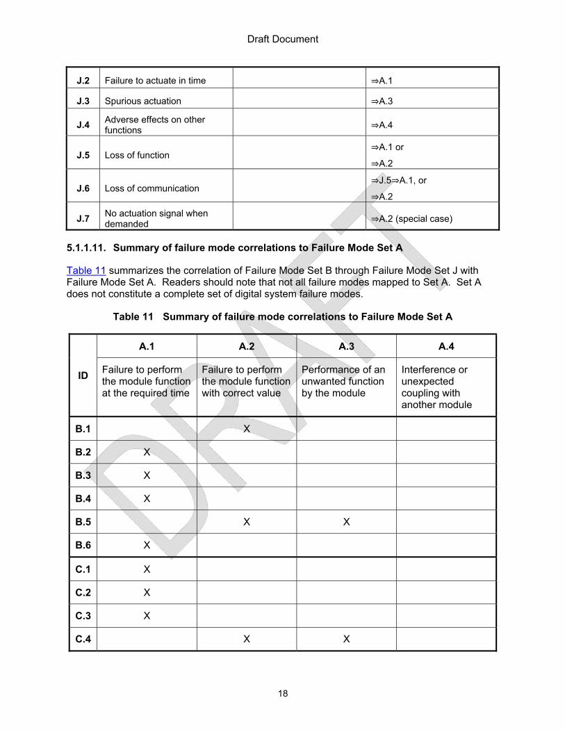
5.1.1.11. Summary of failure mode correlations to Failure Mode Set A
Table 11 summarizes the correlation of Failure Mode Set B through Failure Mode Set J with Failure Mode Set A. Readers should note that not all failure modes mapped to Set A. Set A does not constitute a complete set of digital system failure modes.
Table 11 Summary of failure mode correlations to Failure Mode Set A
ID
A.1 A.2 A.3 A.4
Failure to perform the module function at the required time
Failure to perform the module function with correct value
Performance of an unwanted function by the module
Interference or unexpected coupling with another module
B.1 X
B.2 X
B.3 X
B.4 X
B.5 X X
B.6 X
C.1 X
C.2 X
C.3 X
C.4 X X

Draft Document
19
Table 11 Summary of failure mode correlations to Failure Mode Set A
ID
A.1 A.2 A.3 A.4
Failure to perform the module function at the required time
Failure to perform the module function with correct value
Performance of an unwanted function by the module
Interference or unexpected coupling with another module
C.5 X X
C.6
D.1 X
D.2 X X
D.3
D.4
D.5
D.6 X
E.1 X
E.2 X
E.3 X
E.4 X
E.5
E.6 X
E.7 X
E.8 X
E.9
F.1 X X X
F.2 X
F.3 X

Draft Document
20
Table 11 Summary of failure mode correlations to Failure Mode Set A
ID
A.1 A.2 A.3 A.4
Failure to perform the module function at the required time
Failure to perform the module function with correct value
Performance of an unwanted function by the module
Interference or unexpected coupling with another module
F.4
F.5 X X X X
G.1 X
G.2 X
G.3 X
G.4
H.1
H.2 X
I.1
I.2
I.3
I.4
I.5
I.6
J.1 X
J.2 X
J.3 X
J.4 X
J.5 X X
J.6 X X

Draft Document
21
Table 11 Summary of failure mode correlations to Failure Mode Set A
ID
A.1 A.2 A.3 A.4
Failure to perform the module function at the required time
Failure to perform the module function with correct value
Performance of an unwanted function by the module
Interference or unexpected coupling with another module
J.7 X
Some other reported “failure modes,” are not included in Table 2 through Table 10 because those failure modes could not be related to the system function level or because of differing interpretations of the term “failure mode”. For example, failure modes of digital components such as microprocessors, and static random access memory (SRAM), which can be found in references such as [26], and [29], are not included in Table 2 through Table 10 because the failure modes listed are specified such that they are limited to specific digital components. Appendix B lists examples that do not align with the definition of “failure mode” used in this RIL, but are aligned with the definitions of “fault” or “fault mode.”
5.1.2. A Synthesized Set of Digital System Failure Modes
The failure modes sets in Section 5.1.1 contain duplicates or near duplicates. For the purpose of reporting the progress made with respect to identifying digital I&C failure modes (Objective 2) and to summarize what has been learned from the failure modes in Section 5.1.1, Table 1215 shows a staff synthesized set of the digital system failure modes identified in Section 5.1.1.
Table 12 Characterization of failure modes of a “generic” digital safety system.
ID Failure Mode Elaboration Remarks/Mapping
K.1 No output upon demand Includes no change in output or no response for any input ⟹A.2
K.2 Output without demand e.g.: Unwanted response ⟹A.3
K.3 Output value incorrect Incorrect response to input or set of inputs
⟹A.2
Includes:
• Value too high or too low;
Value stuck at previous value, e.g.: ON, OFF
K.4 Output at incorrect time Too early;
Too late. ⟹A.1
15 If the analysis is limited to the failure modes seen at the external view of the system, it is not sufficient for determining safety assurance of that system. See RIL-1003 for more details.

Draft Document
22
Table 12 Characterization of failure modes of a “generic” digital safety system.
ID Failure Mode Elaboration Remarks/Mapping
K.5 Output duration too short or too long
This mode is specific to continuous functions, and may be viewed as a specific case of E.1.
⟹E.1⟹A.2
K.6 Output intermittent Functions correctly intermittently Example: Loose connection
⟹I.9
No mapping to Failure Mode Set A
K.7 Output flutters
Unwanted oscillation; output fluctuates rapidly Example: Unstable servo-loop.
Could damage equipment.
⟹I.5
No mapping to Failure Mode Set A
K.8 Interference
Affects another system, often resulting from unwanted, unintended interactions, coupling, or side effects.
⟹A.4
K.9 Byzantine behavior
Possible in a distributed system.
Could affect redundant elements of a system
Could be caused by software (e.g. propagating and worsening effect of round-off error).
Could be caused by hardware, (e.g. single-bit hardware fault caused Amazon S3 system failure in 2008). [30]
⇒J.4⇒A.4
Table 12 does not constitute a set of digital system failure modes suitable for assurance16 of a moderately complex system. There may be other system-specific failure modes, worthy of distinct identification, because the corresponding consequences can be distinguished usefully (e.g. nature or severity of loss). An expansion of Failure Mode Set K is unlikely to provide assurance because a safety function in a digital system can be impaired without anything failing and it is unknown how many other system specific failure modes may exist – but the potential number is large. There may be more befitting descriptors with essentially the same meaning for
16 The benefits of further analysis of the failure modes reported in Table 12 (in the context of a moderately complex digital safety system) would be marginal in comparison to failure mode analysis of a traditional hardwired system.

Draft Document
23
the failure modes in failure mode set K. Some examples can be seen in the corresponding failure modes from other sets.
There may be moderately complex systems for which some of the failure modes in set K may not be relevant, (e.g. the consequences may not be distinguishable or the system may not be capable of exhibiting such failure modes). For example, failure mode K.5 could be omitted, if the system provides only discrete outputs, (i.e., does not provide any continuous control function). There may also be moderately complex systems for which additional or failure modes not listed in Set K would apply.
Although failure mode K.5 through failure mode K.8, at some moment, could be construed to be a special case of one of the other failure modes (K.1, K.2, K.3, or K.4) in failure mode set K, these are identified distinctly, because the consequences could be different or the recovery paths could be different.
5.2. Efficacy of SFMEA for Identifying Faults Leading to System Failures
Software is not subject to wear and tear or degradation in the same way as hardware and does not exhibit failure in that sense. It is appropriate to consider system failure modes caused by faulty software. The failure modes identified in Section 5.1 serve as example system failure modes that could be caused by faulty software. Information relevant to staff investigations on the efficacy of Software Fault Modes and Effects Analysis as a method for identifying faults leading to system failure or impairing a safety function (Objective 2) can be found in the appendices to this report. Software faults and fault modes identified in the technical literature reviewed and identified by interviewed experts are reported in Appendix B. The staff found six distinct Software Fault Modes and Effects Analysis (SFMEA) processes which are described in Appendix C: Software Fault Modes and Effects Analysis Methods. None of the methods were developed for purposes of assurance of software or moderately complex digital safety systems with software. In addition to Appendix C, please see NUREG/IA-0254 [3] for more information on SFMEA.

Draft Document
24
6. REGULATORY CONSIDERATIONS
Although there is no NRC acceptance criteria on the format, complexity or conclusions of a failure modes and effects analysis(FMEA) the Code of Federal Regulations (CFR), Title 10, Chapter 1, Regulatory Guides (RG), and other NRC generated documents require or endorse FMEA for documenting analyses of certain requirements (see Digital I&C Interim Staff Guidance #6 [31]).
6.1. Direct References to Failure Mode Identification and Analysis in NRC Regulations
The following regulations that directly mention or require failure modes or failure mode analyses were found:
• 10 CFR 50.34(f)(2)(xxii) states that any application regarding B&W designed plants shall “Perform a failure modes and effects analysis of the integrated control system (ICS) to include consideration of failures and effects of input and output signals to the ICS.”
• 10 CFR 50.73(b)(2)(ii)(E) states that Licensee Event Reports shall contain “The failure mode, mechanism, and effect of each failed component, if known.”
• 10 CFR 50 Appendix A, III. Protection and Reactivity Control Systems
Criterion 23 – Protection System Failure Modes. The protection system shall be designed to fail into a safe state or into a state demonstrated to be acceptable on some other defined basis if conditions such as disconnection of the system, loss of energy (e.g., electric power, instrument air), or postulated adverse environments (e.g., extreme heat or cold, fire, pressure, steam, water, and radiation) are experienced.
• 10 CFR 50, Appendix K, ECCS Evaluation Models, I.D.1 — Single Failure Criterion states that “An analysis of possible failure modes of ECCS equipment and of their effects on ECCS performance must be made.”
6.2. Failure Mode Identification and Analysis and the Single Failure Criterion for Protection and Safety Systems
Although not explicitly required, failure mode identification and analysis has also been used to satisfy the following regulations: • 10 CFR 50.55a(h), Protection and Safety Systems, incorporates by reference IEEE
Standard 603-1991 “IEEE Standard Criteria for safety systems for Nuclear power Generating Stations”, which in Section 5.1, Single Failure Criterion, states that: “The safety systems shall perform all safety functions required for a design basis event in the presence of: (1) any single detectable failure within the safety systems concurrent with all identifiable but non-detectable failures; (2) all failures caused by the single failure; and (3) all failures and spurious system actions that cause or are caused by the design basis event requiring the safety functions. The single-failure criterion applies to the safety systems whether control is by automatic or manual means.”

Draft Document
25
• 10 CFR 50 Appendix A, III. Protection and Reactivity Control Systems
Criterion 21 – Protection System Reliability and Testability. The protection system shall be designed for high functionality reliability and in-service testability commensurate with the safety functions to be performed. Redundancy and independence designed into the protection system shall be sufficient to assure that (1) no single failure results in loss of the protection function and (2) removal from service of any component or channel does not result in loss of the required minimum redundancy unless the acceptable reliability of operation of the protection system can be otherwise demonstrated.
6.3. Failure Mode Identification and Analysis Endorsed in Regulatory Guidance
IEEE 379-2000 [33], which suggests that documentation of a single failure analysis via an FMEA may be acceptable, was endorsed by the staff in RG 1.53, Rev. 2 “Application of the Single Failure Criterion to Safety Systems”[34]. Experience from staff reviews of FMEAs has shown that “Each system must be independently assessed to conclude that FMEA is sufficiently detailed to provide a useful assessment of the potential failures and effects of those failures” [31].
In addition, through Part II of Regulatory Guide 1.70, Revision 3 “Standard Format and Content of Safety Analysis Reports for Nuclear Power Plants, LWR Edition[35], the staff found it acceptable that FMEAs be provided for various systems. Specific to I&C systems [35] states that FMEAs should be provided for the Reactor Trip System according to Section 7.2.2, and Engineered Safety Feature System according to Section 7.3.2. Section 7.7 – Control Systems Not Required for Safety of [35] also states that “analyses should demonstrate that the protection systems are capable of coping with all (including gross) failure modes of the control systems.”
6.4. NRC Staff Reviews of Failure Modes and Failure Mode Analyses
Consistent with regulations and regulatory guidance, failure mode identification and analysis has been useful, as applied in the past by licensees and accepted by the NRC licensing staff for regulatory evaluation (for example, FMEA documentation has been reviewed17 to ensure that the single failure criterion was satisfied18 and has resulted in operational interactions controls such as testing and maintenance19)20.
17 Information reviewed for these purposes is not limited to FMEA documentation.
18 ISG-06[ML11014010] states that “an FMEA is a method for document a single failure analysis which is in accordance with IEEE Std 379-2000 as endorsed by RG 1.53 Rev. 2.”
19 This information is supported by SECY-77-439 [ML060260236]. Supporting evidence can also be found by searching licensee provided License Amendment Requests.
20 FMEA does not address Common Cause Failure (CCF) when a CCF is rooted in some systemic cause such as an engineering deficiency, it is pervasive (i.e., its effects cannot be pinpointed or isolated, but could occur at many hard-to-find places).

Draft Document
26
For new reactor designs, the staff has continued the practice accepting and reviewing FMEAs to ensure that the single failure criterion has been met. FMEAs can be a part of Inspections, Tests, Analyses, and Acceptance Criteria (ITAAC) for systems under development. For example, the US EPR design, US EPR Tier 1, Table 2.4.1-7 (PS ITAAC), item 4.18 requires the performance of an FMEA for the Protection System [36].
6.5. Requirement in IEEE Std 603-1991 Clause 4
For emerging21 digital safety systems, FMEA does not suffice for satisfying a requirement in IEEE Std 603-199122 Clause 4.8, quoted below:
4. Safety system designation. A specific basis shall be established for the design of each safety system of the nuclear power generating station. The design basis shall also be available as needed to facilitate the determination of the adequacy of the safety system, including design changes. The design basis … shall document as a minimum:
…
4.8 The conditions having the potential for functional degradation of safety system performance and for which provisions shall be incorporated to retain the capability for performing the safety functions …..
….
In emerging digital safety systems, “the conditions having the potential for functional degradation of safety system performance” are not limited to a failure of some part of the system. “Functional degradation of safety system performance” can occur due to unintended interactions and couplings, even when no component of the system fails. Therefore, alternative analytical approaches are needed.
21 Characterized by increasing inter-connectivity, interactions, and software content
22 §10CFR50.55a(h)(1) incorporates by reference IEEE Std 603-1991, including the correction sheet dated January 30, 1995.

Draft Document
27
7. SUMMARY AND CONCLUSIONS
Following are the conclusions with respect to the two objectives 1 and 2 as stated in Section 2.
7.1. Objective 1
Ten sets of digital system failure modes were found through expert interviews and additional research activities. None of the failure mode sets reported in this RIL have been endorsed by a standards organization or by broad public consensus. The staff synthesized the failure modes found to report the progress made and to summarize the learning that has occurred. The staff learned that the failure modes found are not applicable to all digital safety systems and that there are major obstacles to identifying all critical failure modes for a moderately complex digital safety system.23 Completeness (of a set of failure modes) is not assurable at this time.
7.2. Objective 2
Appendix C describes six different Software Fault Modes and Effects Analysis techniques. No sound technical basis was found to require that any of the SFMEA techniques be performed or submitted by NRC applicants and licensees. No changes in DI&C regulations or guidance on SFMEA are suggested.
23 A complex system is system in which all safety concerns can be identified and analyzed.

Draft Document
28
8. NEXT STEPS
RIL-1002 will be followed by RIL-1003 which will discuss the feasibility of applying failure mode analysis to quantification of risk associated with digital safety systems. RIL-1003 will complete the staff’s work required in SRM M080605B[1]. No further NRC-funded research on identification of digital system failure modes or software fault modes will be conducted but RES will continue gathering lessons learned from DI&C operating experience and track progress of external research.24
The RES staff is developing the technical basis for the licensing staff to evaluate applicant digital safety system hazard analysis (HA) submissions. Various HA techniques25 are being considered for their suitability to support various aspects of licensing reviews of DI&C safety systems. Results will be reported in a research information letter, RIL-1101. A project has also been established to investigate the use of Safety Demonstration Framework or Assurance Case26 as discussed in Section A.6 of RIL-1001.
Research to establish a framework for assurance of digital safety systems will continue. The RES staff is working with the NRC licensing staff to address related topics outside the scope of this RIL in other ongoing or future RES projects.
24 Such as EPRIs Hazard Analysis Methods for Digital Instrumentation and Control Systems project which, in part, is researched and developed methods for identifying credible failure modes that have the potential to adversely impact nuclear safety and operability [37]. EPRI’s work began because they received industry indication that “Plants are experiencing unexpected/undesired behaviors” from some DI&C systems and from concerns about “Failure modes [that have been] missed or misunderstood” [38]. A report from this research project was published in June 2013 (EPRI Report Number 3002000509) but was not available for review and inclusion in this RIL.
25 FMEA, SFMEA, and Fault Tree Analysis (FTA) are a few HA techniques that will be discussed in RIL-1101.
26 A safety demonstration framework or assurance case seeks to demonstrate the satisfaction of a safety goal through a logical (argument based) organization and integration of evidence from verification, validation, and audit activities in digital system development.

Draft Document
29
9. GLOSSARY
9.1. Selection of Definitions
Expert elicitation participants and technical references identified a divergence and lack of agreement on the vocabulary to discuss the topic with a common understanding [DC, PM, and MH] [39] [40]. The glossary focuses on terms that are not commonly understood in the same way in the sources informing the content of this RIL, removing or reducing ambiguity by selecting and using more specific definitions. Definitions in this RIL are based on definitions traceable to authoritative sources27, approximately in the following selection order:
1. Definitions provided by 10CFR 50 2. IEEE 603 – IEEE Standard Criteria for Safety Systems for Nuclear Power Generating
Stations 3. IEEE Standard 100 4. IEC 60050 5. Other engineering standards 6. Common Acceptable Dictionary
The terms defined are limited to the scope of this RIL. The meanings of compound words, terms, and expressions are derived from the meanings of their constituent words, as defined in this glossary. Where a word is not defined explicitly in the glossary, it is understood in terms of common usage as defined in published dictionaries of the English language. Notes are included to explain the meaning derived from such composition. Notes are also used to explain the derivation or adaptation from published definitions to suit the scope of this document. Notes are also provided where definitions have been modified based on learning that occurred after the public release of RIL-1001.
9.2. Definitions
Assure: Confirm the certainty of correctness of the claim, based on evidence and reasoning.
Notes: 1. For example, by proof
2. Derived forms: 2.1. Assurance 2.2. Assurable 2.3. Assurability
3. Claim: A true-false statement about the value of a defined property of a system. (Adapted from ISO/IEC TR 15026-1:2010 Systems and software engineering – Systems and software assurance – Part 1: Concepts and vocabulary, revised as ISO/IEC DIS 15026-1:2013. Examples: (1) The system is safe. (2) Property X of the system holds.
27 Authoritative sources may choose modify definitions of the terms included in this glossary after public release of this RIL. This RIL communicates intermediate results of a long term NRC Research Project. Definitions of future NRC documents may modify the definitions in this RIL with consideration of new information.
Draft Document
30
4. Evidence: Data supporting the existence or verity of something. (Adapted from 3.1936 in ISO/IEC/IEEE 24765 Systems and software engineering – vocabulary, 2010)
5. Reason: Argument: A logical sequence or series of statements from a premise to a conclusion. (Adapted from http://www.merriam-webster.com/dictionary/argument. Derived forms: 5.1. Reasoning: The use of reason 5.2. Reasonable: Being in accordance with reason. (http://www.merriam-
webster.com/dictionary/reasonable )
Byzantine behavior: In a distributed system, arbitrary behavior in response to a failure or fault [41].
Note: Arbitrary behavior of an element that results in disruption of the intended system behavior. Complexity: (A) (software) The degree to which a system or component has functionality, design or implementation that is difficult to understand and verify. (definition (1)(A) in [42]). (B) (software) Pertaining to any of a set of structure-based metrics that measure the attribute in Definition 1A in Ref. [42]. (definition (1)(B) in [42]). Note 1: There is no universally accepted definition of the term “complexity.”28
The notes below give some other definitions of complexity to illustrate the diversity of perspectives. Note 2: Conversely (changing negative expression to positive) Simplicity: The degree to which a system or component functionality, design or implementation can be understood and verified. Note 3: The number of linearly independent paths (one plus the number of conditions) through the source code of a computer program is an indicator of control flow complexity, known as McCabe's cyclomatic complexity [43]. Note 4: In nontechnical language, we can define the effective complexity of an entity as the length of a highly compressed description of its regularities [44]. Note 5: An ill-defined term that means many things to many people [45]. Note 6: A system is classified as complex if its design is unsuitable for the application of exhaustive simulation and test, and therefore its behavior cannot be verified by exhaustive testing. Source: Defence Standard 00-54, Requirements for safety related electronic hardware in defence equipment, UK Ministry of Defence, 1999.
Component: Constituent, elemental, or most primitive parts of a system.
Control System: (A) “an assemblage of control apparatus coordinated to execute a planned set of control.” (B) a system in which a desired effect is achieved by operating on the various inputs to the system until the output, which is a measure of the desired effect, falls within acceptable range of values.” (C) “A system in which deliberate guidance or manipulation is used to achieve a prescribed value of a variable.” (D) “A system in which a desired effect is achieved
28 Research is needed to clarify complexity within the context of system safety evaluation.

Draft Document
31
by operating on inputs until the output, which is a measure of the desired effect, falls within an acceptable range of values.” Note: All definitions are from [42].
Error: The difference between a computed, observed, or measured value or condition and the true, specified, or theoretically correct value or condition (definition 8A in [42]).
Failure: The termination of the ability of an item to perform a required function [42] [46].29
Notes:
1. The following definitions represent the perspectives of different disciplines to reinforce the definition given above: 1.1. The termination of the ability of an item to perform a required function (Definition (1)(A)
in [42]).
1.2. The termination of the ability of a functional unit to perform its required function (Definition (1)(N) in [42]).
1.3. An event in which a system or system component does not perform a required function within specified limits; a failure may be produced when a fault is encountered (Definition (1)(O) in [42]).
1.4. The termination of the ability of an item to perform its required function (Definition 9 in [42] from “nuclear power generating station”).
1.5. The loss of ability of a component, equipment, or system to perform a required function (Definition 13 in [42] Safety systems equipment in “nuclear power generating stations”).
1.6. An event that may limit the capability of equipment or a system to perform its function(s) (Definition 14 in [42] “Supervisory control, data acquisition, and automatic control”).
1.7. The termination of the ability of an item to perform a required function (Definition 15 in [42] “nuclear power generating systems”)
2. After failure, the item has a fault [46]. 3. “Failure” is an event, as distinguished from “fault” which is a state [46].
4. This concept as defined does not apply to items consisting of software only [46].
Failure mode: (A) The effect by which a failure is observed to occur (adapted from definition 1 in [42]). (B) The manner in which failure occurs. (adapted from definition 4 in [42]). Note - A failure mode is usually characterized by the manner in which a failure occurs.
Fault: (A) 30 the state of an item characterized by inability to perform a required function, excluding the inability during preventive maintenance or other planned actions, or due to lack of external resources [46].
Notes
29 Reference [46] includes a note that this concept as defined does not apply to items consisting of software only.
30 Definition A has been added to the definition of Fault used in RIL-1001 because of learning that occurred while performing supplemental research activities for RIL-1002.

Draft Document
32
1. A fault is often the result of a failure of the item itself but may exist without prior failure. (191-05-01 in[46])
2. Following are other definitions, relating “fault” and “defect”:
a. a defect or flaw in a hardware or software component (Definition 13 in[42]
b. a defect in a hardware device or component; for example, a short circuit or broken wire (Definition 9 in [42])
c. Synonym: physical defect
3. The following definition is specific to software: An incorrect step, process, or data definition in a computer program (Definition (7)(A) in [42]).
Fault Mode: One of the possible states of a faulty item, for a given required function [46].
Fault Tree Analysis (FTA): An analysis to determine which fault modes of the subitems or external events, or combinations thereof, may result in a stated fault mode of the item, presented in the form of a fault tree [191-16-05 in [46]]
Hazard: Potential for harm
Hazard Analysis (HA): the process of examining a system throughout its lifecycle to identify inherent hazards and contributory hazards, and requirements and constraints to eliminate, prevent, or control them.
Notes:
1. “Hazard identification” part of HA includes the identification of losses (harm) of concern.
2. This definition is narrower than many definitions of HA, some of which correspond to the NRC’s usage of the term “safety analysis” (as in a safety analysis report).
a. The scope of the definition excludes the verification that the requirements and constraints have been satisfied.
b. Various HA definitions and descriptions identify artifacts (results, including intermediate results) of HA by different names. The expression “requirements and constraints” used in this definition (to align and integrate them in well-established systems engineering terms) subsumes them.
c. The scope of the definition does not include quantification explicitly. Where appropriate (e.g. for a hardware component, quantification of its reliability would be implicit in the activity of formulating requirements and constraints).
Latent Fault: An existing fault that has not been recognized.
Mistake: (A) A human action that produces an unintended result (definition 1 in [42]: electronic computation). Note: Common mistakes include incorrect programming, coding, and manual operation [42]. (B) A human action that produces an incorrect result (definition C [42]: software).

Draft Document
33
Safety System: System designed (1) to initiate automatically the operation of appropriate systems including the reactivity control systems, to assure that specified acceptable fuel design limits are not exceeded as a result of anticipated operational occurrences [10CFR 50, Appendix A, Criterion 20]; and (2) to sense accident conditions and to initiate the operation of systems and components important to safety [10CFR 50, Appendix A, Criterion 20]. (3) A system that is relied upon to remain functional during and following design basis events to ensure: (i) the integrity of the reactor coolant pressure boundary, (ii) the capability to shut down the reactor and maintain it in a safe shutdown condition, or (iii) the capability to prevent or mitigate the consequences of accidents that could result in potential off-site exposures comparable to the 10 CFR Part 100 guidelines [32].31
Note: IEEE 603-2009 states that “a safety system shall encompass all of the elements required to achieve a safety function.” In addition, “safety functions include but are not limited to the following: a) Emergency negative reactivity insertion, b) Emergency core cooling, c) Post-accident radiation removal, d) Containment isolation, and e) Post-accident heat removal.” [48]
Software Fault Mode and Effects Analysis: A qualitative method of reliability analysis, which involves the study of the fault modes, which can exist in every sub item of the item, and the determination of the effects of each fault mode on other sub items of the item and on the required functions of the item.
System: A combination of interacting elements organized to achieve one or more stated purposes [49].
31 A safety system includes but is not limited to a) emergency negative reactivity insertion, b) Emergency core cooling, c) Post-accident radiation removal, d) Containment isolation, and e) Post-accident heat removal.

Draft Document
34
10. EXPERTS CONSULTED
Table 13 identifies experts consulted during the NRC’s DI&C expert elicitation activity, including the symbols used in this RIL to refer to them. Table 14 identifies experts consulted after NRC’s DI&C expert elicitation activity, including the symbols used in this RIL to reference their names.
Table 13 Experts interviewed During NRC’s DI&C Expert Elicitation Activity.
Abbreviation Expert and Affiliation
Abbreviation Expert and Affiliation
AW Alan Wassyng
McMaster University JH
Jorgen Hansson Carnegie-Mellon University
BJ Barry Johnson
University of Virginia JM
John McDermid University of York
CW Chris Johnson
University of Glasgow LS
Lorenzo Stringini City University, London
DC Darren Cofer
Rockwell Collins MB Manfred Broy
Technical University of Munich
DD Dan Dvorak NASA JPL
MD Mike Dewalt
Federal Aviation Administration
DW David Ward MIRA Ltd.
MH Michael Holloway
NASA Langley
GH Gerard Holzman
NASA JPL PJ
Paul Jones Food and Drug Administration
JH Jamie Harper
NASA Goddard PM
Paul Miner NASA Langley
JB Jens Braband
TS RA SD RAMSS RB
Robin Bloomfield City University, London
JG John Goodenough
Carnegie Mellon University SS
Stefan Schaan Siemens
JK John Knight
University of Virginia SP
Steve Prusha NASA JPL

Draft Document
35
Table 14 Experts Consulted During Additional NRC Research Activities.
Abbreviation Expert and Affiliation
Communications with NRC
HH Herbert Hecht
SoHaR Inc. Tele-meeting October 10,
2010
PG Pete Goddard
TRW Automotive Tele-meeting September
10, 2010
RC Ram Chillarege Chillarege Inc.
Tele-meeting September 1, 2010
RL Robyn Lutz NASA JPL
Private Communications w. S. Birla
SG Sergio Guarro
Asca Inc
Informal Presentations December 22, 2010 and
February 23, 2011

Draft Document
36
11. CITED LITERATURE
[1] A. Vivietti-Cook, “SRM M8065B, Memorandum: Staff Requirements Meeting with Advisory Committee on Reactor Safeguards (ACRS), Thursday June 5, 2008, Commissioners’ Conference Room, One White Fling North, Rockville, MD [ML081780761],” Jun. 2008, Available: http://www.nrc.gov/reading-rm/doc-collections/commission/srm/meet/2008/m20080605b.pdf, ADAMS Accession Number: ML081780761.
[2] US Nuclear Regulatory Commission, “Research Information Letter 1001: Software-Related Uncertainties in the Assurance of Digital Safety Systems - Expert Clinic Findings, Part 1,” Available: http://pbadupws.nrc.gov/docs/ML1112/ML111240017.pdf, ADAMS Accession Number: ML111240017.
[3] L. Betancourt, S. Birla, J. Gassino, and P. Regnier, NUREG/IA 0254 Suitability of Fault Modes and Effects Analysis for Regulatory Assurance of Complex Logic in Digital Instrumentation and Control Systems, Nuclear Regulatory Commission, 2011 Available: www.nrc.gov/readin-rm/doc-collectios/nuregs/agreement/ia0254/ia0254.pdf, ADAMS Accession Number: ML11201A179.
[4] R.W. Borchardt, “Response to Advisory Committee on Reactor Safeguards Recommendations on Draft Final Digital Instrumentation and Control Interim Staff Guidance-06, ‘Licensing Process’,” Dec. 2010, ADAMS Accession Number: ML103130193.
[5] “United States Nuclear Regulatory Commission Briefing on Digital Instrumentation and Control Transcript,” Jun. 2009, Available: http://www.nrc.gov/reading-rm/doc-collections/commission/tr/2009/20090604a.pdf.
[6] US Nuclear Regulatory Commission, “Final PRA Policy Statement,” Aug. 1995, Available: http://www.nrc.gov/reading-rm/doc-collections/commission/policy/60fr42622.pdf.
[7] T.L. Chu, G. Martinez-Guridi, M. Yue, J. Lehner, and P. Smanta, NUREG/CR 6962 Traditional Probabilistic Risk Assessment Methods for Digital Systems (NUREG/CR 6962), US Nuclear Regulatory Commission, 2008 Available: http://pbadupws.nrc.gov/docs/ML0831/ML083110448.pdf, ADAMS Accession Number: ML0803110448.
[8] W. Shack, “DIGITAL INSTRUMENTATION AND CONTROL SYSTEMS INTERIM STAFF GUIDANCE, ACRS Letter to NRC Commission,” Apr. 2008, ADAMS Accession Number: ML081050636.
[9] US Nuclear Regulatory Commission, Interim Staff Guidance on Review of New Reactor Digital Instrumentation and Control Probabilistic Risk Assessments Available: http://pbadupws.nrc.gov/docs/ML0805/ML080570048.pdf.
[10] ACRS, “Advisory Committee on Reactor Safeguards 551st Meeting Transcript,” Apr. 2008, Available: www.nrc.gov/reading-rm/doc-collections/acrs/tr/fullcommitee/2008/acrs041108-551.pdf
[11] US Nuclear Regulatory Commission, “US Nuclear Regulatory Commission Meeting with

Draft Document
37
Advisory Committee on Reactor Safeguards Transcript,” Available: www.nrc.gov/readin-rm/doc-collections/commission/tr/2008/20080605b.pdf
[12] US, NRC Digital System Research Plan FY 2010-FY 2014 Available: http://pbadupws.nrc.gov/docs/ML1005/ML100541484.pdf, ADAMS Accession Number: ML100541484.
[13] S. Abdel-Khalik, “Draft Final Digital Instrumentation & Control Interim Staff Guidance-06: Licensing Process,” Oct. 2010, ADAMS Accession Number: ML102850357.
[14] Erin Engineering, Benefits and Risks Associated with Expanding Automated Diverse Actuation System Functions, EPRI, 2008 Available: http://pbadupws.nrc.gov/docs/ML0908/ML090860465.pdf, ADAMS Accession Number: ML090860465.
[15] R.W. Borchardt, “Status of The Nuclear Regulatory Commission Staff Efforts to Improve the Predictability and Effectiveness of Digital Instrumentation and Control Reviews,” Available: http://www.nrc.gov/reading-rm/doc-collections/commission/secys/2009/secy2009-0061/2009-0061scy.pdf.
[16] P. Haapanen, STUK-YTO-TR 190 Failure mode and effects analysis of software-based automation systems, Helsinki: Radiation and Nuclear Safety Authority, 2002.
[17] T. Stålhane, S. Farfeleder, and O. Daramola, “Safety Analysis Based On Requirements,” Available: www.cesearproject.edu.
[18] T.-L. Chu, G. Martinez-Guridi, M. Yue, P. Samanta, G. Vinod, and J. Lehner, Workshop on Philosophical Basis for Incorporating Software Failures in A Probabilistic Risk Assessment Available: http://pbadupws.nrc.gov/docs/ML0927/ML092780607.pdf, ML092780607.
[19] B.J. Czerny, J.G. D’Ambrosio, B.T. Murray, and P. Sundaram, 2005-01-0785 Effective Application of Software Safety Techniques for Automotive Embedded Control Systems, Warrendale, PA: SAE International, 2005 Available: http://www.sae.org/technical/papers/2005-01-0785.
[20] SAE, SAE ARP 5580 SAE ARP 5580, Recommended Failure Modes and Effects Analysis (FMEA) Practices for Non-Automotive Applications, 2001.
[21] P.L. Goddard, “Software FMEA Techniques,” Proceedings of the Annual Reliability and Maintainability Symposium, IEEE, 2000, pp. 118–123 Available: http://ieeexplore.ieee.org/lpdocs/epic03/wrapper.htm?arnumber=816294.
[22] K. Korsah, M.D. Muhlheim, and D.E. Holcomb, ORNL/TM-2006/626 Industry Survey of Digital I&C Failures, Oak Ridge National Laboratory/Nuclear Regulatory Commission, 2007 Available: http://www.ornl.gov/~webworks/cppr/y2007/rpt/125413.pdf.
[23] ANSI/IEEE, ANSI/IEEE 500-1984 IEEE Standard Reliability Data for Pumps and Drivers, Actuators, and Valves, ANSI/IEEE, 1984 Available: http://ieeexplore.ieee.org/lpdocs/epic03/wrapper.htm?arnumber=35066.
[24] N. Bidokhti, “How FMEA Improves Hardware and Software Safety & Design Reuse,”

Draft Document
38
International Workshop on Software Reuse and Safety (RESAFE-2006), Torino, Italy: Available: www.favaro.net/john/RESAFE2006/papers/Bidokhti.pdf.
[25] J. Murdoch, J.A. McDermid, and P. Wilkinson, “Failure Modes and Effects Analysis (FMEA) and Systematic Design,” International System Safety Conference, 2001 Available: ftp://ftp.cs.york.ac.uk/pub/hise/Failure%20Modes%20&%20Effects%20Analysis.pdf.
[26] T.-L. Chu, M. Yue, G. Martinez-, and J. Lehner, “A Generic Failure Modes and Effects Analysis (FMEA) Approach for Reliability Modeling of Digital Instrumentation and Control (I&C) Systems,” 10th International Probabilistic Safety Assessment and Management Conference, Seattle, Washington: 2010.
[27] T.-L. Chu, M. Yue, and W. Postma, “A Summary of Taxonomies of Digital System Failure Modes Provided by the DIGREL Task Group,” PSAM 11, Helsinki, Finland: 2012, ADAMS Accession Number: ML120680552.
[28] J.-E. Holmberg, S. Authén, and A. Amri, “Development of Best Practice Guidelines on Failure Modes Taxonomy Reliability Assessment of Digital I&C Systems for PSA,” PSAM 11, Helsinki, Finland: 2012.
[29] S.M. Cetiner, K. Korsah, and M.D. Muhlheim, “Survey on Failure Modes and Failure Mechanisms in Digital Components and Systems,” NPIC&HMIT (2009), Sixth American Nuclear Society International Topical Meeting on Nuclear Plant Instrumentation, Control, and Human-Machine Interface Technologies, LaGrange Park, IL: American Nuclear Society, 2009.
[30] Amazon S3 Team, “Amazon S3 Availability Event July 20, 2008,” Amazon Web Services Available: http://status.aws.amazon.com/s3-20080720.html.
[31] NRC, Licensing Process Interim Staff Guidance, Nuclear Regulatory Commission, 2011 Available: http://pbadupws.nrc.gov/docs/ML1101/ML110140103.pdf, ADAMS Accession Number ML110140103.
[32] IEEE 603-1991, IEEE Standard Criteria for Safety Systems for Nuclear Power Generating Stations, 1991 Available: http://ieeexplore.ieee.org/lpdocs/epic03/wrapper.htm?arnumber=159411.
[33] IEEE 379-2000, IEEE Standard Application of the Single Failure Criterion to Nuclear Power Generating Station Safety Systems Available: http://standards.ieee.org/findstd/standard/379-2000.html.
[34] US Nuclear Regulatory Commission, Regulatory Guide 1.53 Rev. 2, Application of the Single Failure Criterion to Safety Systems Available: http://pbadupws.nrc.gov/docs/ML0332/ML033220006.pdf.
[35] US Nuclear Regulatory Commission, Part II of Regulatory Guide 1.70 Rev. 3, Standard Format and Content of Safety Analysis Reports for Nuclear Power Plants, LWR Edition Available: http://pbadupws.nrc.gov/docs/ML0113/ML011340108.pdf, ADAMS Accession Number: ML011340108.

Draft Document
39
[36] AREVA NP, Inc., “AREVA Design Control Document Rev. 3 - Tier 1 Chapter 02 - System Based Design Descriptions and ITAAC - Sections 2.4 Instrumentation of Control Systems - 2.4.1 Protection System,” Aug. 2011, Available: http://pbadupws.nrc.gov/docs/ML1123/ML11231A066.pdf, ADAMS Accession Number: ML11231A066.
[37] B.J. Geddes and R.C. Torok, “Digital System Failure Mode Analysis Methodologies,” NPIC&HMIT (2010), Las Vegas, Nevada: American Nuclear Society, 2010, pp. 1690–1696.
[38] R. Torok and B. Geddes, “Systems Theoretic Process Analysis (STPA) Applied to a Nuclear Power Plant Control System,” Mar. 2013, Available: http://psas.scripts.mit.edu/home/wp-content/uploads/2013/04/02_EPRI_MIT_STAMP_Mar2013.pdf.
[39] N.G. Leveson, Safeware: System Safety and Computers, Addison-Wesley Professional, 1995.
[40] SoHaR, “Software Failure Modes and Effects Analysis {FMEA},” Nov. 2011, Available: www.sohar.com/proj_pub/download/SoHaR_FMEA_Final.pdf.
[41] F. Schneider, Understanding Protocols for Byzantine Clock Synchronization, Cornell University, Available: http://hdl.handle.net/1813/6699.
[42] IEEE “IEEE Standards Dictionary: Glossary of Terms and Definitions,” IEEE Std 100-2000.
[43] T.J. McCabe, “A Complexity Measure,” IEEE Transactions on Software Engineering, vol. SE-2, Dec. 1976, pp. 308–320.
[44] M. Gell-Mann and S. Lloyd, “Effective Complexity,” Jun. 2003, Available: http://www.santafe.edu/media/workingpapers/03-12-068.pdf.
[45] G.W. Flake, The computational beauty of nature: computer explorations of fractals, chaos, complex systems, and adaptation, Cambridge, Mass: MIT Press, 1998 QA76.6 .F557 1998.
[46] IEC 60050-191 International Electrotechnical Vocabulary - Chapter 191: Dependability and Quality of Service, IEC, 1990.
[47] “NRC: Glossary -- Reasonable” Available: http://www.nrc.gov/reading-rm/basic-ref/glossary/reasonable.html.
[48] IEEE Standard 603-2009, Standard Criteria for Safety Systems for Nuclear Power Generating Stations, 2009 Available: http://ieeexplore.ieee.org/lpdocs/epic03/wrapper.htm?arnumber=5325914.
[49] IEEE Std 15288-2008 “Systems and Software Engineering System Life Cycle Processes,” ISO/IEC 15288:2008(E) (Revision of IEEE Std 15288-2004, 2008), pp. 1–84.

Draft Document
40
[50] C. Eckert, “Identification and Elimination of Systemic Problems,” Proceedings of the Society of Maintenance and Reliability Professionals Annual Symposium, St. Louis, MO: 2009.

Draft Document
41
12. LITERATURE REVIEWED BUT NOT CITED
[NC1] IEEE, “A Discussion of the Term Failure Mode,” IEEE Std 500-1984, Dec. 1983, pp. 22–26.
[NC2] D. Vallespir and J. Herbert, “A Framework to Evaluate Defect Taxonomies,” 2009.
[NC3] N. Ozarin and M. Siracusa, “A process for failure modes and effects analysis of computer software,” Reliability and Maintainability Symposium, 2003. Annual, 2003, pp. 365–370.
[NC4] T.L. Chu, G. Martinez-Guridi, M. Yue, and J. Lehner, “A Review of Software-Induced Failure Experience,” American Nuclear Society 5th Int. Meeting on Nuclear Power Instrumentation Control and Human Machine Interface Technology, American Nuclear Society, 2006.
[NC5] W. Li and H. Zhang, “A software hazard analysis method for automotive control system,” Computer Science and Automation Engineering (CSAE), 2011 IEEE International Conference on, 2011, pp. 744–748.
[NC6] E. Fronczak, “A top-down approach to high-consequence fault analysis for software systems,” PROCEEDINGS The Eighth International Symposium On Software Reliability Engineering, 1997, p. 259.
[NC7] ACRS, “ACRS Digital I&CS Subcommittee Transcript,” Jun. 2011, Available: www.nrc.gov/reading-rm/doc-collections/acrs/agenda/2011/ ADAMS Accession Number: ML111932A216.
[NC8] B.J. Czerny, J.G. D’Ambrosio, P.O. Jacob, B.T. Murray, and P. Sundaram, 2004-01-1666 An Adaptable Software Safety Process for Automotive Safety-Critical Systems, Warrendale, PA: SAE International, 2004 Available: http://www.sae.org/technical/papers/2004-01-1666
[NC9] C. Price and N. Snooke, “An Automated Software FMEA,” Singapore: 2008 Available: hdl.handle.net/2160/519
[NC10] M. Grottke, A.P. Nikora, and K.S. Trivedi, “An empirical investigation of fault types in space mission system software,” Dependable Systems and Networks (DSN), 2010 IEEE/IFIP International Conference on, 2010, pp. 447–456.
[NC11] K. Korsa, M.S. Cetiner, M.D. Mulheim, and Poore III, Willis P., “An Investigation of Digital Instrumentation and Control System Failure Modes,” 7th ANS Topical Meeting on Nuclear Power Plant Instrumentation, Control, and Human-Machine Interface Technology, Las Vegas, Nevada: 2010 Available: http://www.osti.gov/bridge/product.biblio.jsp?osti_id=1038464
[NC12] K. Robinson, “Ariane 5: Flight 501 Failure - A Case Study of Errors,” Mar. 2011, Available: www.cse.unsw.edu.au/~se4921/PDF/ariane5-article.pdf
Draft Document
42
[NC13] US Nuclear Regulatory Commission, “Branch Technical Position 7-21: Guidance on Digital Computer Real-Time Performance, Revision 5 [ML070550070],” Mar. 2007, ADAMS Accession Number: ML070550070.
[NC14] M. Rausand, “Chapter 3: System Analysis - Failure Modes, Effects, and Criticality Analysis Presentation,” Oct. 2005, Available: www.ntnu.no/ross/slides/fmeca.pdf
[NC15] M. Rausand, “Chapter 3: System Analysis - Failures and Failure Classification Presentation,” May. 2005, Available: www.ntnu.no/ross/slides/failure.pdf
[NC16] B.M. Cook, “Classification of I&C Systems: A Practical Approach,” NPIC&HMIT 2010, Las Vegas, Nevada: American Nuclear Society, 2010, pp. 99–119.
[NC17] A. Vivetti-Cook,, “COMGEA-11-0001 – UTILIZATION OF EXPERT JUDGMENT IN REGULATORY DECISION MAKING,” Mar. 2011, ADAMS Accession Number: ML110740304.
[NC18] G. Apostolakis, “COMGEA-11-0001, UTILIZATION OF EXPERT JUDGMENT IN REGULATORY DECISION MAKING,” Jan. 2011, Available: www.nrc.gov/reading-rm/doc-collections/commission/comm-secy/2011/2011-0001comgea.pdf, ADAMS Accession Number: M110200139.
[NC19] US Nuclear Regulatory Commission, Common Q Safety Evaluation, Non-Proprietary Version ML003740165.
[NC20] H. Hecht, X. An, and M. Hecht, “Computer Aided Software FMEA,” Computer Press, 2004.
[NC21] A. Avizienis, “Dependability and Its Threats: A Taxonomy,” Building the Information Society:, J.-C. Laprie, B. Randell, and R. Jacquart, eds., Boston: Kluwer Academic Publishers, 2004, pp. 91–120.
[NC22] P. Sundaram, “Development of A Simulation Model for System Safety Analysis Presentation,” Jun. 2005, Available: www.mathworks.com/atomotive/iac/presentations/sundaram.pdf
[NC23] R.R. Lutz and I.C. Mikulski, “Empirical analysis of safety-critical anomalies during operations,” Software Engineering, IEEE Transactions on, vol. 30, 2004, pp. 172–180.
[NC24] R. Lutz and A. Nikora, “Failure Assessment,” ISHEM ’05, Napa, CA: 2005.
[NC25] R. Lutz and A. Nikora, “Failure Assessment Presentation,” Nov. 2005.
[NC26] Reliability Analysis Center, 94-12203 Failure Mode, Effects, and Criticality Analysis (FMECA), Reliability Analysis Center, 1993.
[NC27] Omnicon Group Inc., “Failure Modes and Effects Analysis (Brochure),” Feb. 2004, Available: www.omnicongroup.com/images/pdf/brochures/OmniconSWFMEABrochureRevJ8.5x11.pdf

Draft Document
43
[NC28] N. Ozarin, “Failure modes and effects analysis during design of computer software,” IEEE, 2011, pp. 201–206 Available: http://ieeexplore.ieee.org/lpdocs/epic03/wrapper.htm?arnumber=1285448.
[NC29] M. Hecht, E. Shokri, S. Meyers, E. Nguyen, W. Greenwell, and A. Lam, “Failure Modes and Effects Analysis for a Software-Intensive Satellite Control System,” 26th International System Safety Conference 2008: ISSC 2008�; Vancouver, Canada, 25 - 29 August 2008, Red Hook, NY: Curran, 2009, pp. 612–622.
[NC30] D.R. Wallace and D.R. Kuhn, “Failure Modes in Medical Device Software: an Analysis of 15 Years of Recall Data,” 2001, pp. 301–311.
[NC31] D. Andra, “Failure Modes Presentation,” 2002, Available: www.wdtb.noaa.gov/workshop/wdm/originals/FailureModes.ppt
[NC32] PNNL, “Failure Modes: Meaning, Identification & Analysis In SW-Intensive DI&C System For Nuclear Power Plant Safety Functions (Draft, PNNL D19.Second Evolution),” Dec. 2009.
[NC33] M. Dixit, D. Brenchley, S. Shoemaker, R. Sullivan, and J. Young, “Failure Modes: Meaning, Identification & Analysis is SW-Intensive DI&C Systems (Draft PNNL Report, D19),” Feb. 2010.
[NC34] H. Zhang, “Fast Abstract: A Study on SFMEA method for UML-based Software,” 20th International Symposium on Software Reliability Engineering, Mysuru, India: IEEE Computer Society, 2009 Available: www.issre009.org/content/fast-abstract-papers#266
[NC35] W.E. Vesely, F.F. Goldberg, N.H. Roberts, and D.F. Haasl, NUREG 0492 Fault Tree Handbook, 1981.
[NC36] N. Bidokhti, “FMEA is not enough,” IEEE, 2009, pp. 333–337 Available: http://ieeexplore.ieee.org/lpdocs/epic03/wrapper.htm?arnumber=4914698
[NC37] Westinghouse, WCAP-16438-NP, Rev.3, APP-GW-JJ-004, Rev. 0 FMEA of AP1000 Protection and Safety Monitoring System (Non-Proprietary), 2011 ADAMS Accession Number: ML110670191.
[NC39] Federal Aviation Administration, “Guide to Reusable Launch and Reentry Vehicle Reliability Analysis,” Apr. 2005, Available: www.faa.gov/about/office_org/headquarters_offices/ast/licenses_permits/media/FAA_AST_Guide_to_Reliability_Analysis_v1.pdf
[NC40] IEC, IEC 61508, Edition 2.0, International Standard: Functional Safety of Electrical/Electronic/Programmable Electronic Safety Related Systems - Part 4: Definitions and Abbreviations, IEC, 2010.
[NC41] B. Li, “Integrating Software into PRA (Probabilistic Risk Assessment),” PHD, University of Maryland, College Park, 2004.

Draft Document
44
[NC42] L. Buglione and A. Abran, “Introducing Root-Cause Analysis and Orthogonal Defect Classification at Lower CMMI Maturity Levels,” Available: citeseerx.ist.psu.edu/viewdoc/download?doi=10.1.1.90.3192.pdf
[NC43] G.Y. Park, D.I. Kim, and C.H. Jung, “Issues on Validation of Programmable Logic Design for Digital Instrumentation and Control System,” NPIC&HMIT (2010), Las Vegas, Nevada: American Nuclear Society, 2010, pp. 954–963.
[NC44] N. Carte and D. Halverson, “Licensing Process for Digital Safety Systems,” NPIC&HMIT 2010, Las Vegas, Nevada: American Nuclear Society, 2010, pp. 1001–1008.
[NC45] AREVA NP Inc., ANP-10310NP Methodology for 100% Combinatorial Testing of the U.S. EPR(TM) Priority Module, Non-Proprietary Version, AREVA NP Inc., 2011 ADAMS Accession Number: ML111010480.
[NC46] B. Nolan, B. Brown, L. Balmelli, T. Bohn, and U. Wahli, Model Driven Systems Development With Rational Products, [United States?]�: IBM, International Technical Support Organization, 2008.
[NC47] N. Snooke, “Model-based Failure Modes and Effects Analysis of Software,” Available: http://citeseerx.ist.psu.edu/viewdoc/summary?doi=10.1.1.2.1253
[NC48] N. Snooke and C. Price, “Model-driven automated software FMEA,” IEEE, 2011, pp. 1–6 Available: http://ieeexplore.ieee.org/lpdocs/epic03/wrapper.htm?arnumber=5754453.
[NC49] T.L. Chu, M. Yue, G. Martinez-Guridi, K. Mernick, J. Lehner, and A. Kuritzky, NUREG/CR-6997 Modeling a Digital Feedwater control System Using Traditional Probabilistic Assessment Methods, Brookhaven National Laboratory/NRC, 2009 Available: www.nrc.gov/reading-rm/doc-collections/nuregs/contract/cr6997/cr6997.pdf
[NC50] J. Taylor, “Motor Failure Modes,” 2010, Available: www.machineryhealthcare.com
[NC51] R. Stattel, “Oconee Digital Safety System Licensing Experience,” NPIC&HMIT (2010), Las Vegas, Nevada: American Nuclear Society, 2010, pp. 977–991.
[NC52] B. Geddes, N. Thuy, and R. Torok, 1016731 Operating Experience Insights on Common-Cause Failures in Digital Instrumentation and Control Systems, EPRI, 2008 Available: http://www.epri.com/abstracts/Pages/ProductAbstract.aspx?ProductId=000000000001016731
[NC53] J. Dehlinger and R.R. Lutz, “PLFaultCAT: A Product-Line Software Fault Tree Analysis Tool,” Automated Software Engineering, vol. 13, Jan. 2006, pp. 169–193.
[NC54] N. Bidokhti, “Practical Software Failure Analysis Presentation,” Jun. 2008, Available: www.opsalacarte.com/pdfs/Tech_Papers/Practical_SW_Failure_Analysis_for_Applied_Reliability_Symposium_June_2008.pdf
[NC55] E. Piljugin, S. Authén, and J.-E. Holmberg, “Proposal for the Taxonomy of Failure Modes of Digital System Hardware for PSA,” PSAM 11, Helsinki, Finland: 2012.

Draft Document
45
[NC56] G.-Y. Park, H.-S. Eom, S.-W. Cheon, S.-C. Jang, and D.-H. Kim, “Quantitative Safety Analysis of Nuclear Safety Software,” NPIC&HMIT (2010), Las Vegas, Nevada: American Nuclear Society, 2010, pp. 1297–1304.
[NC57] Duke Energy /Oconee Nuclear Station, RPS/ESPS Failure Modes and Effects Analysis Summary Calculation, Non-Proprietary Version, 2009 ADAMS Accession Number: ML091770437.
[NC58] G.-Y. Park, K.C. Kwon, E. Jee, K.Y. Koh, and P.H. Seong, “Safety Activities on Safety-Critical Software for Reactor Protection System,” Transactions of the American Nuclear Society (ANS), vol. 96, Jun. 2007, pp. 237–238.
[NC59] J. Liu, J. Dehlinger, and R. Lutz, “Safety Analysis of Software Product Lines Using State-Based Modeling,” IEEE, 2011, pp. 21–30 Available: http://ieeexplore.ieee.org/lpdocs/epic03/wrapper.htm?arnumber=1544718
[NC60] N. Leveson, “Safety and Hazard Analysis Presentation,” Fall. 2004, Available: www.students.cs.uwaterloo.ca/~se101/Safety.pdff
[NC61] M. Wetherholt, “SFMECA/SFTA” Presentation, Apr. 2009.
[NC62] M. Graham, “Software Defect Prevention Using Orthogonal Defect Classification Presentation,” Jan. 2005, Available: twin-spin.cs.umn.edu/node/844.
[NC63] J.B. Bowles and C. Wan, “Software failure modes and effects analysis for a small embedded control system,” IEEE, 2011, pp. 1–6 Available: http://ieeexplore.ieee.org/lpdocs/epic03/wrapper.htm?arnumber=902433
[NC64] G.-Y. Park, “Software FMEA Analysis for Safety Software,” International Conference on Nuclear Engineering, Brussels, Belgium: ASME
[NC65]WCAP-16592-NP, Revision 2 Software Hazard Analysis of AP1000TM Protection and Safety Monitoring System (Non-Proprietary), 2010 ML103370195.
[NC66] G.-Y. Park, S.-W. Cheon, K.C. Kwon, K.Y. Koh, P.H. Seong, E. Jee, and S. Cha, “Software Qualification Activities for Safety Critical Software,” NPIC&HMIT (2009), Tennessee: American Nuclear Society, 2009.
[NC67] G.-Y. Park, H.-S. Eom, D.-H. Kim, and H.G. Kang, “Software Reliability Assessment of Reactor Protection System,” Transactions of the American Nuclear Society (ANS), vol. 103, 2010.
[NC68] T. Hobson, “Software Safety: Examples, Definitions, Standards, Techniques,” Nov. 2008, Available: www.cs.not.ac.uk/~cah/G53QAT/Schedule08.html
[NC69] European Cooperation for Space Standardization, ECSS-Q-80-03 Space Product Assurance: Methods and Techniques to Support the Assessment of Software Dependability and Safety (Draft), 2006 Available: www.ecss.nl/forums/ecss/dispatch.cgi/home/showfile/100623/d20060426090708/No/Draft-ECCS-Q-80-03A(1March2006).pdf.

Draft Document
46
[NC70] NASA, NSTS 22206 Revision D Space Shuttle: Requirements for Preparation and Approval of Failure Mode and Effects Analysis (FMEA) and Critical Items List (CIL), 1993.
[NC71] R.J. Duphily, Aerospace Report No. TOR-2009(8591)-13 Space Vehicle Failure Modes, Effects, and Criticality Analysis (FMECA) Guide, 2011 Available: www.everyspec.com/USAF/TORs/TOR2009-8591-13_21606
[NC72] NASA, “Standard for Performing a Failure Mode and Effects Analysis (FMEA) and Establishing a Critical Items List (CIL) (DRAFT): Flight Assurance Procedure (FAP)- 322-209,” Nov. 2011, Available: rsdo.gsfc.nasa.gov/documents/Rapid-III-Documents/MAR-Reference/GSFC-FAP-322-208-FMEA-Draft.pdf
[NC73] R.R. Lutz, “Targeting safety-related errors during software requirements analysis,” SIGSOFT Softw. Eng. Notes, vol. 18, Dec. 1993, pp. 99–106.
[NC74] S. Perry, R.L. Wears, and R.I. Cook, “The Role of Automation in Complex System Failures,” Journal of Patient Safety, vol. 1, Mar. 2005, pp. 56–61.
[NC75] N. Ozarin, “The Role of Software Failure Modes and Effects Analysis for Interfaces in Safety-and Mission-Critical Systems,” IEEE, 2008, pp. 1–8 Available: http://ieeexplore.ieee.org/lpdocs/epic03/wrapper.htm?arnumber=4519009.
[NC76] C. Raspotnig, V. Katta, A.L. Opdahl, and T. Stålhane, HWR 1002 Towards Approaches for Analysis and Argumentation of Systems Safety and Security: Comparison of Techniques and Conceptual Model, 2011.
[NC77] AREVA NP Inc., ANP-10309NP U.S. EPR Protection System: Technical Report, Non-Proprietary Version, 2011 Available: http://pbadupws.nrc.gov/docs/ML1119/ML11195A295.pdf, ADAMS Accession Number: ML11195A295
[NC78] R. Lutz and A. Patterson-Hine, “Using Fault Modeling in Safety Cases,” IEEE, 2008, pp. 271–276 Available: http://ieeexplore.ieee.org/lpdocs/epic03/wrapper.htm?arnumber=4700333.
[NC79] R. Lutz, “What Software Product Lines Can Tell Us about Sustainable, Long-lived Systems,” Nov. 2009 Available: http://www.cs.iastate.edu/~sandeepk/publications/SPLC10_lutz_weiss_krishnan_yang.pdf
[NC80] J. Gray, Technical Report 85.7 Why Do Computers Stop and What Can Be Done About It?, 1985 Available: www.hpl.hp.com/techreports/tandem/TR-85.7.html.

Draft Document
A-1
APPENDIX A. THE VOCABULARY RELATED TO FAILURE MODES – A DISCUSSION
Terms such as failure, fault, defect, error, and mode are commonly used in different ways, leading to ambiguity and confusion. To avoid misunderstanding, RIL-1002 uses each of these terms as defined in the Glossary32 and based on authoritative33 sources. This discussion explains the rationale underlying the selected definitions.
The scope and context of this discussion is limited34 to a software-reliant DI&C safety system, performing monitoring and control functions, where the criticality is of the highest level and the system consists of safety related elements only.
The discussion starts with an introduction of basic concepts (failure; fault; defect; error; mistake; stimulus-response; event-action; state and mode) and progresses to a combination of those concepts (e.g. fault mode) demonstrating the consistency of the combinational terms with the constituent terms and the value maintaining such consistency.
A.1. Failure
In the context of engineered systems, especially those with sensors, actuators and control logic, the term “failure” has been used to mean “termination of the ability of an item to perform a required function” 35 [1](also see [2] and definitions 1A, 1N, 1O, 9, 13, 14 and 15 in [3]). The term, “failure” implies that the system or component of concern was once able to perform its required function [MB]. Failure is an event [1], signifying termination or loss of function. This widely accepted definition is similar to and consistent with the definition of “single failure” stated in 10 Code of Federal Regulations (10 CFR) Part 50 Appendix A, “A single failure means an occurrence which results in the loss of capability of a component to perform its intended safety functions.” In this definition, “loss of capability” has the same meaning as “termination of the ability” in the IEC definition given above. The term, “occurrence” in the definition given in 10 CFR Part 50 Appendix A maps into the term, “event” mentioned above and in reference [1].
The concept of “failure” is well-known, well-accepted and well understood in the context of physical components and systems with physical elements. Physical components fail as a result of applied excessive loading, or wear and tear due to physical degradation processes or mechanisms. Examples of failure of physical systems and components (which were functioning correctly) include:
1. A fluid flow control (shut-off) valve is unable to stop or resume flow. 2. A motor is unable to provide motion, motive force or motive torque.
32 Exceptions arise when quoting or citing references, which use these terms in meanings different from the one in the RIL-1002 glossary.
33 Authoritative definitions are those accepted with a broad consensus, usually evidenced by inclusion in an accepted standard by a reputable standards organization.
34 While the discussion may have much broader applicability, the scope is kept narrow for ease of explanation.
35 This definition is widely accepted.
Draft Document
A-2
3. A pipe is no longer able to transport fluid from its source to destination at a specified flow rate.
4. A resistor ceases to provide the specified resistance.
A.2. Reason for Avoiding the Term “Failure” for Software
The concept of “failure” as explained in Section A.1 does not apply to software [1]. Some experts assert that use of the term, failure, for software may be meaningless or perhaps misleading [DC, PM, and MH]. The rationale is that “Software does not exhibit random wear-out failures as does hardware; it is an abstraction… [4]. That is, “Software itself does not fail; it is a design for a machine … Software-related computer [system] failures are always systematic” [4]
Software items are of a different nature than hardware items in the applicability of the concept of failure, as explained above. If the software item does not perform a function under a specific condition, it was not able to do so from the beginning of operation. “If the item is a software system or component and is able to perform its function correctly from inception, it will continue to perform its function; it will not break” [MB]. A software item either performs a function under a given condition or it does not; the ability to perform a function is never lost. That is, software does not break down or wear out. This is why the term “failure” as defined in the glossary should not be used for a software item.
A.3. Fault
The International Electrotechnical Vocabulary, in 191-05-01, defines “fault” as the state of an item characterized by inability to perform a required function, excluding the inability during preventive maintenance or other planned actions, or due to lack of external resources.”[5]
Note the close relationship of this definition with the definition of failure “termination of the ability of an item to perform a required function,” where “termination of the ability” is an EVENT. Then, fault is the resulting STATE of the item. Also, note that an item need not “fail” to reach a fault state. It may be faulty (it may be in a state characterized by the inability to perform a required function) to begin with, as discussed in Section A.2 above in the case of software.
The International Electrotechnical Vocabulary, in 191-05-20, defines “latent fault” as “an existing fault that has not yet been recognized” (i.e. discovered) [5]. In software operating in a system of highest criticality (e.g. for nuclear reactor safety, one would not expect the system to be commissioned with a known fault in the safety critical software). However, the system may still have a latent fault, particularly if it is complex. In such a system, testing, by itself, cannot assure the absence of a fault. For that reason, other approaches are needed to defend against a potential latent fault.
In [3] definition 14 characterizes “fault” as a defect36 in a hardware or software component, where the term, defect, connotes a deficiency or inadequacy that may impair the intended function. However, some researchers distinguish between fault and defect as follows: a fault is a logical (function level) abstraction, whereas a defect is described in terms of some physical
36 In software, it is “designed in” [DC, GH], i.e. resulting from some inadequacy in its engineering, rather than resulting from degradation. In hardware, it may also be the result of some inadequacy in its manufacturing, fabrication, or construction.

Draft Document
A-3
characteristic. It may be possible to map many defects at the physical or implementation level into a single fault at the function level. Then, the abstraction reduces the number of conditions or cases to be considered in an analysis. On the other hand, a single defect at the physical or implementation level may lead to multiple faults at the function level. Therefore, “fault” and “defect” it would be more useful and less confusing to treat fault and defect as different concepts, and the definition of fault, given in the International Electrotechnical Vocabulary should be used.
Appendix B provides examples of faults and a discussion on potential classification schemes.
A.4. Error
Often, the term “error” is used in the sense of “defect” or “fault” as evident in many of the surveyed publications. Furthermore, often, in the same system or the same publication, the term “error” is also used in other ways.
The community interested in “fault tolerant systems” does not recommend using “error” to mean “fault” or “defect.” In the context of this discussion, usage of the term, error, is limited to mean, “Any discrepancy between a computed, observed, or measured value or condition and the true, specified, or theoretically correct value or condition (adapted from combination of definitions 1 and 12 in [3]). This definition is consistent with definitions 3A, 4, 5, 6, 8A, 11, and 12 [3]. Note that even the selected definition allows for a wide range of usages. For example, in a closed loop control system, the specified value may be the setpoint and the discrepancy between the observed value and the setpoint may not indicate any unwanted or undesirable behavior; in fact, it may be natural to the control scheme and the controlled system.
Many of the surveyed publications have also used the term, “error” to mean a human mistake. To avoid ambiguity, RIL-1002 avoids usage of the term, “error” in that meaning. A mistake is defined as a human action (or inaction) that produces an unintended or incorrect result (adapted from definitions 1 and 3 in [3]).
ISO/IEC/IEEE 24765:2010(E) in 3.1719 (definition of mistake) notes that “The fault tolerance discipline distinguishes between a human action (a mistake), its manifestation (a hardware or software fault), the result of the fault (a failure), and the amount by which the result is incorrect (the error).” [6]
A.5. Stimulus-Response, Event-Action, State-Mode – Concepts to Characterize Behavior
The stimulus-response relationship is a useful paradigm to characterize behavior in many fields of science and provides the underpinning for conceiving, specifying, designing, analyzing, and evaluating engineered systems. Discretization of the behavior space (e.g. into sub-behaviors) is a useful way of decomposing or organizing the problem space (or requirements space) for an engineered system. For example, certain sub-behaviors can only occur under certain conditions or are required only under certain conditions. The concept of discretizing the behavior space is used in engineering safety into engineered systems, e.g. detection of a hazardous condition, such as failure (a change in condition) of a critical valve, and using it as a stimulus to select (switch to) mitigating behavior.

Draft Document
A-4
An occurrence of some change37 in conditions can be abstracted into the concept, “event.” When this change serves as a stimulus to enable an action or to select some group of actions (i.e. change in sub-behavior) or to cause an action by an item, the concept of “event” is useful in understanding, describing or specifying the behavior of the item. Following are some other examples of an event, given in ISO/IEC/IEEE 24765-2010 (E) [6]:
• A timer expiration • An external interrupt • An internal signal • An internal message
The existence of a certain set of stable conditions can be abstracted into the concept “state.” For example, the state may be an abstraction of the values of a set of variables that characterize the behavior of an item. In the example of the valve, introduced earlier, its two stable states for normal operation are: OPEN; CLOSED.
Mode is defined (definition 8 in [3] and definition 1 in ISO/IEC/IEEE 24765-2010 (E) §3.1806 [6]) as a set of related features or functional capabilities of a product. Mapping into the vocabulary used in the discussion above, “product” maps into “item” and “set of related features or functional capabilities” maps into sub-behavior.
These standards cite the following examples: • On-line mode • Off-line mode • Maintenance mode
Taking the example of an operating nuclear reactor, the term “mode” is used to refer to different sub-behaviors or groups of behaviors, e.g.
• On power (starting up; raising power; operating at reduced power; operating at full power; reducing power)
• Hot shut down(reactor is sub-critical and coolant temperature is above a certain threshold)
• Cold shut down (reactor is sub-critical and coolant temperature is below a certain threshold)
• etc.
From these examples, it can be seen that the term “mode” and “state” are related, such that the term “mode” clusters a number of states into one region of related behaviors. The term, “state” can also be used in this manner (i.e. a state can be an abstraction of a set of finer-grained states). Technically, “mode” and “state” have the same meaning; the differences lie in popular usage.
With the various examples given above, it can be seen that the state-based event-driven paradigm38 provides a unified means to describe or specify normal operational, as well as off-normal non-operational behaviors. The vocabulary used to characterize different kinds of conditions should be consistent with this paradigm.
37 Example in the case of a normally functioning valve: Termination of its ability to perform its required function.
38 Example formalisms: Finite state machine or automaton; extended finite state machine.

Draft Document
A-5
A.6. Failure Modes
Although the term, “failure mode” is used very commonly, its usage is not supported by the International Electrotechnical Vocabulary 60050 Chapter 191: Dependability and Quality of Service, amended, 1999-03[5].
IEEE Std 500-1984 P&V (withdrawn) defines “Failure Mode” as the effect39 by which a failure is observed to occur [7]. However, even for components such as pumps, valves, and actuators, which are simpler than the DI&C systems being introduced in NPPs, the authors of this standard found differences in usage and intended meanings of the basic terms.
IEEE Std 500-1984 P&V in Section 1.3, defines failure as “the termination of the ability of an item or equipment to perform a required function.” Essentially this definition is the same as in Section A.1 above.
In order to assist in a common understanding and usage of basic terms, IEEE Std 500-1984 P&V published Appendix A [8], discussing these terms. In its Section A5, it recognized “failure” to be an event, as characterized in Section A.1 above. IEEE Std 500-1984 P&V in Section 1.3 defines failure mode as “the effect by which a failure is observed to occur.” Then, IEEE Std 500-1984 P&V, in Section A5 of the Appendix, explains that “A failure mode provides a descriptive characterization of the failure event in generic terms” with the intent of distinguishing the term, “failure mode” from the mechanism causing the failure and from the effect40 propagated to a higher level assembly or other elements of a system with multiple levels of assembly.
In contrast, the International Electrotechnical Vocabulary has deprecated the terms “failure mode,” “failure modes and effects analysis”, and” failure modes, effects and criticality analysis.” However, this discussion uses the term “failure mode” while referring to usage in cited publications [5]. In the examples of failures given in Section A.1, each is an example of one “failure mode41” for each type of component. For a given type of component, there may be several “failure modes”, e.g. the following “failure modes” of a fluid flow control (shut-off) valve, which has two stable states (open; closed), and changes state, responding to inputs (OPEN; CLOSE):
1. No output upon demand: If it receives input to change its state, it does not, i.e. it stays where it is
2. Output without demand: It changes state without input... 3. Output at incorrect time: State change is not completed within the required time interval
after input. 4. Output intermittent: Upon receiving input, sometimes the valve responds correctly, but
not at other times (exhibiting one of the other failure modes in this list42):
39 Effect does not have the same meaning here, as denoted by the letter E in FMEA.
40 Here, effect has the meaning denoted by the letter E in FMEA.
41 The term is used herein as used popularly, although inconsistent with ISO/IEC 60051-191 [1].
42 Comparing this list with the failure modes K.1-K.8 in Table 3, K.5 and K.8 are not applicable to the 2-position valve: K.5 applies to an element with continuous control and K.8 applies to a distributed system.

Draft Document
A-6
5. Output flutters: When the input signal. OPEN, is given, the valve does not change from the CLOSED state to a stable OPEN state, but its position fluctuates; or, when the input signal. CLOSE, is given, the valve does not transition from the OPEN state to a stable CLOSED state, but its position fluctuates
In each of the five modes above, the behavior is exhibited in repeated occurrences of the input.
A.7. Fault Modes
A term related to fault is “fault mode” which is defined as “one of the possible states of a faulty item, for a given required function [1]. Referring to the example of the valve given in Section A.3, according to IEC 60051-191 [1] these are fault modes – not failure modes. The subject of fault modes for software items is further discussed in Appendix B.
A.8. Appendix A Bibliography
[1] IEC, “IEC 60050-191 International Electrotechnical Vocabulary - Chapter 191: Dependability and Quality of Service,” IEC, IEC60050-191, 1990.
[2] US Nuclear Regulatory Commission, “Research Information Letter 1001: Software-Related Uncertainties in the Assurance of Digital Safety Systems - Expert Clinic Findings, Part 1.”
[3] IEEE, “IEEE 100 The Authoritative Dictionary of IEEE Standards Terms Seventh Edition,” IEEE Std 100-2000, 2000.
[4] Nancy G. Leveson, Safeware: System Safety and Computers. Addison-Wesley Professional, 1995.
[5] IEC, “IEC 60050-191 International Electrotechnical Vocabulary - Chapter 191: Dependability and Quality of Service,” IEC, IEC60050-191, 1990.
[6] IEEE, “24765-2010 - Systems and Software Engineering -- Vocabulary,” Standard 24765-2010, 2010.
[7] ANSI/IEEE, “IEEE Standard Reliability Data for Pumps and Drivers, Actuators, and Valves,” ANSI/IEEE, ANSI/IEEE 500-1984, 1984.
[8] IEEE, “A Discussion of the Term Failure Mode,” IEEE Std 500-1984, pp. 22–26, Dec.1983.

Draft Document
B-1
APPENDIX B. IDENTIFIED SOFTWARE FAULTS AND FAULT MODES SETS
Section 5.1.1 reported digital system I&C failure modes identified during the expert elicitation process and supplemental NRC research activities. This appendix reports the software faults43, fault modes44, and classification and taxonomy schemes that were identified.45
Due to the large number of faults and fault modes found, correlation analysis and fault synthesis similar to failure mode correlation and synthesis in Sections 5.1.1.11 and 5.1.2 was not performed. The staff also could not assemble a set of faults and fault modes of greatest concern for software that could be used for assurance of a moderately complex digital safety systems. Experts indicated that it may not be possible to generate a complete list of suitable faults and fault modes and expressed doubt that defect free software can be produced [JK, GH, MH].
B.1. Software Faults and Fault Modes Identified by Source
This section presents some fault and fault mode sets found through the expert elicitation process and supplemental NRC research activities. The staff found that faults, fault modes, and effects resulting from activated faults or fault modes were often identified in the technical literature as “failure modes” or “software failure modes.” After analyzing the information available, more faults and fault modes were found than can be presented.46 The faults and fault mode sets presented reported are limited to references reviewed for the purposes listed in Section 1.2 of RIL-1002. Other characterizations of the faults and fault mode sets presented are possible. The same faults and fault modes (but worded differently) may be repeated in several sets.
B.1.1. Fault/Fault Mode Set 1
In his paper, “How FMEA Improves Hardware and Software Safety & Design Reuse”47 [3], N. Bidokhti states that “there are many categories” of software faults and provides five example categories: Requirements faults, Interface faults, Fault Tolerance faults, Resource Usage faults, and Data faults.
43 The state of an item characterized by inability to perform a required function, excluding the inability during preventive maintenance or other planned actions, or due to lack of external resources” [1].
44 One of the possible states of a faulty item for a required function [2].
45 Consistent definitions of the terms “failure”, “failure mode” and “fault” are not used in the technical literature. This appendix reports “faults” as defined in this RIL. The sources cited may have referred to faults as errors, failures, bugs, etc. See the Glossary and Appendix A for information on the definitions chosen for RIL-1002.
46 Terminology consistent with definitions used in this RIL replaces the original wording in this section where possible in the tables below. It was not possible to replace the terminology by some authors.
47 This is the same source of Failure Mode Set G in Section 5.1.1.7.

Draft Document
B-2
Example faults and fault modes are provided in the paper, organized into two of the example categories: Requirement Faults and Interface faults. The author seems to acknowledge that his examples and definitions may not be suitable for every situation. He states that it is essential that “definition of [faults], categories of [faults], and [fault] modes are well understood and accepted by all team members,” before any identification and analysis begins.
Table B-1 Fault/Fault Mode Set 1 [3].
ID Faults Fault Modes Remarks
1.1 Incorrect requirements
No specific fault modes identified for these faults.
These faults are examples of the Requirement Fault
category in [3]
These faults could apply to any item of any software
product..
1.2 Ambiguous requirements
1.3 Conflicting requirements
1.4 Exceptional condition not specified
1.5 Test points or monitors not specified
1.6
Message based interface fault
No message received
This is examples of Interface Fault Category
used in [3]
1.7 Invalid message received
1.8 Message received out of sequence.
1.9 Duplicate message received
1.10 Message not acknowledged
1.11 Message acknowledged out of sequence
1.12 Duplicate acknowledge received
B.1.2. Fault/Fault Mode Set 2
In their paper titled “Failure Modes in Embedded Systems and Its Prevention” [4], stated that two main groups of faults are possible: hardware and software. The authors state that their list contains “some examples” of software faults.
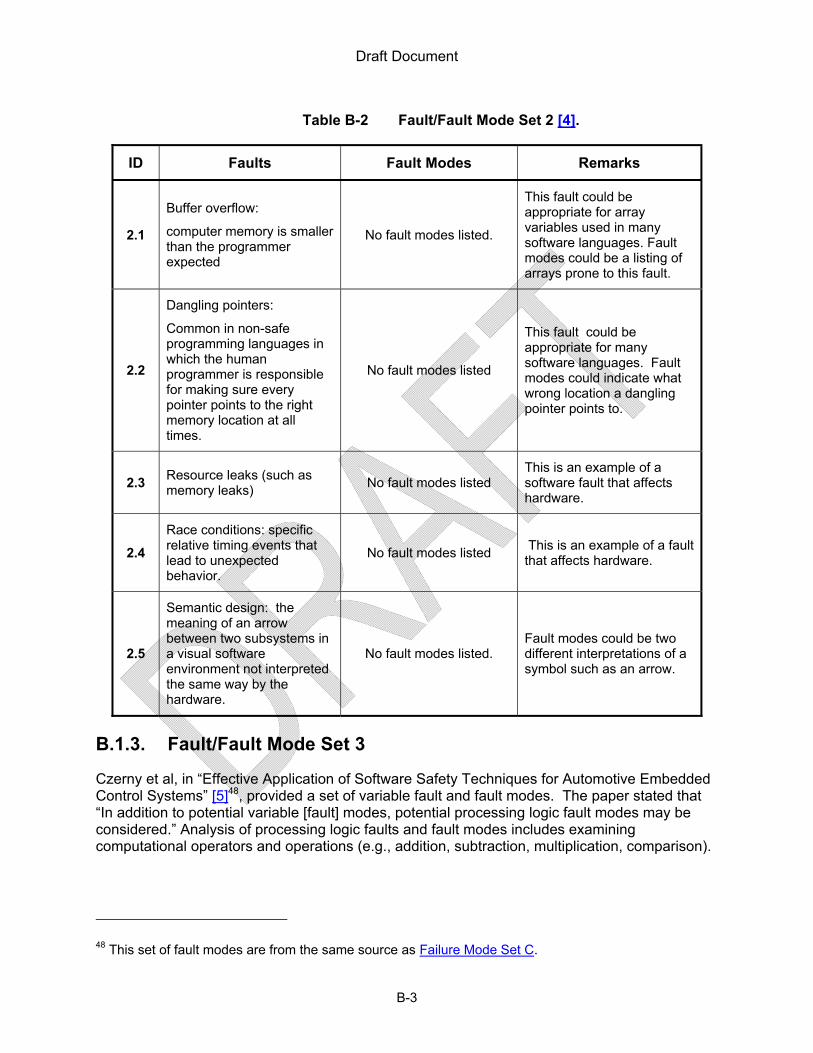
Draft Document
B-3
Table B-2 Fault/Fault Mode Set 2 [4].
ID Faults Fault Modes Remarks
2.1
Buffer overflow:
computer memory is smaller than the programmer expected
No fault modes listed.
This fault could be appropriate for array variables used in many software languages. Fault modes could be a listing of arrays prone to this fault.
2.2
Dangling pointers:
Common in non-safe programming languages in which the human programmer is responsible for making sure every pointer points to the right memory location at all times.
No fault modes listed
This fault could be appropriate for many software languages. Fault modes could indicate what wrong location a dangling pointer points to.
2.3 Resource leaks (such as memory leaks)
No fault modes listed This is an example of a software fault that affects hardware.
2.4
Race conditions: specific relative timing events that lead to unexpected behavior.
No fault modes listed This is an example of a fault that affects hardware.
2.5
Semantic design: the meaning of an arrow between two subsystems in a visual software environment not interpreted the same way by the hardware.
No fault modes listed. Fault modes could be two different interpretations of a symbol such as an arrow.
B.1.3. Fault/Fault Mode Set 3
Czerny et al, in “Effective Application of Software Safety Techniques for Automotive Embedded Control Systems” [5]48, provided a set of variable fault and fault modes. The paper stated that “In addition to potential variable [fault] modes, potential processing logic fault modes may be considered.” Analysis of processing logic faults and fault modes includes examining computational operators and operations (e.g., addition, subtraction, multiplication, comparison).
48 This set of fault modes are from the same source as Failure Mode Set C.

Draft Document
B-4
Table B-3 Fault/Fault Mode Set 3 [5].
ID Faults Fault Modes Elaboration
3.1 Variable type – Analog
Fault
High
Low
3.2 Variable Type – Boolean
Fault
True when False
False when True
3.3
Enumerated Example Values
Faults
A when it should be B,
B when it should be C,
C when it should be A, or
C when it should be B
B.1.4. Fault/Fault Mode Set 4
A paper by Vyas and Mittal, “Operation Level Safety Analysis for Object Oriented Software Design Using SFMEA” [6], presents a bottom up approach to identifying faults and fault modes in methods used in object oriented code. Four fault and fault mode cause types are listed as “failure modes”: “Precondition Violation Failure Modes, Parametric Failure Modes, Method Call or Invoke Failure Modes, and Post Conditional Failure Modes.”
Table B-4 Fault/Fault Mode Set 4 [6].
ID Faults Fault Modes Remarks
4.1 Incorrect method response with precondition violated
None reported
Cause Type: “Precondition Violation Failure Modes”
4.2 Precondition satisfied but corresponding exception is raised.
None reported.
4.3
Constraints on Parameter Value faults
Constraint is false but exception is not raised, constraint is true but exception is raised.
Cause Type: “Parametric Failure Modes”
4.4 Method m1 invokes m2 in wrong order (if invocation of m2 is condition based)
None reported. Cause Type: “Method Call or Invoke Failure Modes” (m1 and m2 are of the same

Draft Document
B-5
Table B-4 Fault/Fault Mode Set 4 [6].
ID Faults Fault Modes Remarks
4.5 M1 invokes m2 by wrong parameters (if m2 is parameterized)
None reported.
class)
4.6
M1 (of class A) fails to invoke m2 (of class B) because lack of instance of class B
None reported.
Cause Type: “Method Call or Invoke Failure Modes” (m1 and m2 are of different classes)
4.7 M1 invokes m2 in wrong order (if invocation of m2 is condition based)
None reported.
4.8 M1 invokes m2 by wrong parameters (if m2 is parameterized)
None reported.
4.9 None reported None Reported Cause Type: “Post Conditional Failure Modes”
B.1.5. Fault/Fault Mode Set 5 NUREG/CR – Appendix C (BNL)
This fault set was obtained from a document that was originally an appendix to NRC NUREG/CR-6962[7]. The appendix did not appear in the final document but it was released publically for feedback from the Advisory Committee on Reactor Safeguards [8].
Table B-5 Fault/Fault Mode Set 5 [8].
ID Faults Fault Modes Remarks
5.1
Software runs into an infinite loop
Software stops generating outputs and deadlocks between processes. More specific fault modes include:
Halt/Termination with Clear message, and
Halt/Termination without clear message.
Effect listed as “system failure mode”: Software Stalls
5.2
Software generates incorrect output.
Runs with evidently wrong results, and
Runs with wrong results that are not evident.
Effect listed as “system failure mode”: Software runs as usual but with wrong outputs.

Draft Document
B-6
The fault modes listed could also be viewed as local effects but they do meet the definition of “fault mode” used in this RIL.
5.3
Software runs with misleading commands to the user, incomplete or incorrect display of information.
Incomplete or incorrect information displayed.
The following effects were listed as “software failure modes”:
Incomplete or incorrect display of information requiring operators to take action, and
Misleading command to the user.
5.4 Timing/order fault None reported.
This is really a fault “category [that] represents incorrect timing and ordering of events; for example, race conditions, execution time exceeding a time limit, incorrect timing of available data, incorrect rate of data processing, incorrect duration of data for processing, and slow response.”
5.5 Interrupt induced fault None reported.
This is really an “interrupt induced” fault category such as “incorrect interrupt request, service, and return.”
5.6 Omission of a function or attribute fault.
None reported. None.
5.7 Unintended function or attribute fault.
None reported.
This is really a “category [that] represents unintended actions or attributes … (e.g., modifying variables that should not be modified, and modifying code memory, in addition to the correctly implemented function or attribute).
5.8 Incorrect implementation of a function or an attribute fault.
None reported. None.

Draft Document
B-7
5.9 Data faults. None reported.
This is really a “category … related to data” such as “incorrect amount, incorrect value, incorrect range, …” etc.
B.1.6. Fault/Fault Mode Set 6
In their paper, “Experience Report: Contributions of SFMEA to Requirements Analysis” [9], Lutz and Woodhouse postulated four data faults types and four event fault types. The data fault types are: Absent Data, Incorrect Data, Timing of Data Wrong, and Duplicate Data. The event fault types are: Halt/Abnormal Termination, Omission, Incorrect Logic/Event, and Timing/Order.
Table B-6 Fault/Fault Mode Set 6 [9].
ID Faults Fault Modes Remarks
6.1
Lost or missing messages, absence of sensor input data, lack of input or output, failure to receive needed data, missing commands, missing updates of data values, data loss due to hardware failures, software process or sensor does not send the data needed for correct functioning.
None reported. Absent Data Fault Type
6.2
Bad data, flags or variables set to values that don’t accurately describe the spacecraft’s state or the operating environment, erroneous triggers, limits, deadbands, delay timers, erroneous parameters, wrong command outputs, or wrong parameters to the right commands, spurious or unexpected signals.
None reported. Incorrect Data Fault Type
6.3
Data arrive too late to be used or be accurate, or too early to be used or be accurate; obsolete data are used in control decisions (data age), inadvertent, spurious (unexpected) or
None reported.
Timing of Data Wrong Fault Type

Draft Document
B-8
transient data.
6.4 Redundant copies of data, data overflow, data saturation.
None reported. Duplicate Data Fault Type
6.5
Open, stuck, hung, and deadlocked at this point (event) in the process. None reported.
Listed as “Halt/Abnormal Termination” Fault Type. A Halt/Abnormal Termination is an effect using the terminology of this RIL.
6.6
Event does not to occur but process continues execution, jumps, skips, short.
None reported. Omission Fault Type
6.7
Behavior is wrong, logic is wrong, branch logic is reversed, wrong assumptions about state, preconditions, “don’t cares” aren’t truly so; event (e.g. command issued) is wrong to implement the intent or requirement.
None reported. Incorrect Logic/Event Fault Type
6.8
Event occurs at wrong time or in wrong order, event occurs too early, too late, the sequence of events is incorrect, an event that must precede another event doesn’t occur as it should, iterative events occur intermittently rather than regularly, events that should occur only once instead occur iteratively.
None reported. Timing/Order Fault Type
B.1.7. Fault/Fault Mode Set 7
In the paper titled “FMEA Performed on the Spinline3 Operational System Software as Part of the TIHANGE 1 NIS Refurbishment Safety Case” [10], Ristord and Esmenjaud provided a list of “five general failure modes.” This list of “five general failure modes” contains effects (as defined by this RIL): the operating system stops, the program stops with a clear message, the program stops without a clear message, the program runs producing obviously wrong results, and the program runs producing apparently correct but wrong results. The authors also defined “context specific” faults for code that was grouped into blocks of code instructions referred to as “block instructions.” Correct operation was defined first; the faults identified.

Draft Document
B-9
Table B-7 Fault/Fault Mode Set 7 [10].
ID Faults Fault Modes Remarks
7.1 The block instructions execution does not end through the “exit” point
None reported.
Although these faults were identified by analyzing specifically grouped sets of instructions (code), these faults could occur in completely different code.
7.2 The block instruction execution time does not meet time limits
None reported.
7.3
The block instruction does not perform the intended actions or performs unintended actions:
It does not provide expected outputs
It modifies the variables that it shall not modify
It does not interact as expected with I/O boards
It does not interact as expected with CPU resources
It modifies code memory or constants
None reported.
B.1.8. Fault/Fault Mode Set 8
Becker and Flick, in their paper “A Practical Approach to Failure Modes, Effects, and Criticality Analysis (FMECA) for Computing Systems” [11], lists “some typical” faults and fault modes organized into categories describing the effect of the faults and fault modes. The categories included effects at the software and hardware level. Hardware effects not listed in Table B-8 include: slow response, startup failure, and loss of external system.
Table B-8 Fault/Fault Mode Set 8 [11]
ID Faults Fault Modes Remarks
8.1 Unsolicited termination of the normal and correct processing
No fault mode provided. In category: Hardware or software stop
8.2 No fault provided. Termination of required processing without an
In category: Hardware or

Draft Document
B-10
Table B-8 Fault/Fault Mode Set 8 [11]
ID Faults Fault Modes Remarks associated notification of termination.
software crash
8.3
No fault provided. Process ceases to perform its required services but continues performing actions and consumes resources without notification of its status.
In category: Hardware or software hang.
Remark: the fault would be activated under specific conditions.
8.4 Duplicate messages Application in a different
end state. In category: Faulty message
8.5 Application failing to send a message.
No fault mode provided. In category: Missed message
8.6 Fault (specific fault not provided) occurs while writing a checkpoint file.
Checkpoint file not in a consistent state
In category: Checkpoint file failure
8.7 No fault provided. Design limit of size of a
database is reached. Internal capacity exceeded
8.8 No fault provided. Application is unable to
send a service request message.
In category: Loss of service
B.1.9. Fault/Fault Mode Set 9 – WGRisk Activities
Chu et al, in [12], identified faults and fault modes by considering the architecture of an example digital system. Table B-9 lists the faults and fault modes identified by examining “the software program running on a particular microprocessor.”
Table B-9 Fault/Fault Mode Set 9 [12].
ID Faults Fault Modes Remarks
9.1 Erroneous operation of data acquisition
Incorrect value
Incorrect validity
No value
No validity
9.2 Erroneous operation for logic processing
Failure to actuate (including failure to hold)

Draft Document
B-11
Spurious failure
9.3 Erroneous operation for voting logic
Incorrect voting
No vote
9.4 Erroneous operation for priority actuation logic
Incorrect priority
No priority
B.1.10. Fault/Fault Mode Set 10
The faults and fault modes found in IEEE Standard 1044TM-2009 [1] standard are listed in Table B-10. Examples of faults listed in the standard are for information only and are not exhaustive. Additional information on this standard is provided in Section B.2.2.
Table B-10 Fault/Fault Mode Set 10 [1].
ID Fault Fault Modes Remarks
10.1
Defect in data definition, initialization, mapping, access, or use, as found in a model, specification or implementation.
Variable not assigned initial value or flag
Incorrect data type or column size
Incorrect variable name used
Valid range undefined
Incorrect relationship cardinality in data model
Missing or incorrect value in pick list
10.2
Defect in specification or implementation of an interface (e.g., between user and machine, between two internal software modules, between software module and database, between internal and external software components, between software and hardware, etc.)
Incorrect module interface design or implementation
Incorrect report layout (design or implementation)
Incorrect or insufficient parameters passed
Cryptic or unfamiliar label or message in user interface
Incomplete or incorrect message sent or displayed
Missing required field on data entry screen
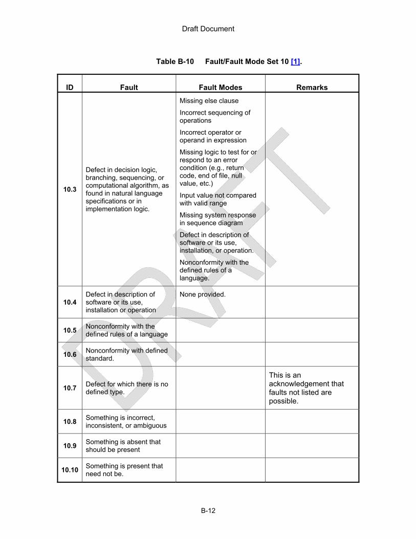
Draft Document
B-12
Table B-10 Fault/Fault Mode Set 10 [1].
ID Fault Fault Modes Remarks
10.3
Defect in decision logic, branching, sequencing, or computational algorithm, as found in natural language specifications or in implementation logic.
Missing else clause
Incorrect sequencing of operations
Incorrect operator or operand in expression
Missing logic to test for or respond to an error condition (e.g., return code, end of file, null value, etc.)
Input value not compared with valid range
Missing system response in sequence diagram
Defect in description of software or its use, installation, or operation.
Nonconformity with the defined rules of a language.
10.4 Defect in description of software or its use, installation or operation
None provided.
10.5 Nonconformity with the defined rules of a language
10.6 Nonconformity with defined standard.
10.7 Defect for which there is no defined type.
This is an acknowledgement that faults not listed are possible.
10.8 Something is incorrect, inconsistent, or ambiguous
10.9 Something is absent that should be present
10.10 Something is present that need not be.

Draft Document
B-13
Table B-10 Fault/Fault Mode Set 10 [1].
ID Fault Fault Modes Remarks
10.11
Defects inserted during requirements definition activities (e.g., elicitation, analysis or specification):
Function required to meet customer goals omitted from requirements specification.
Incomplete use case specification
Performance requirements missing or incorrect
Security requirements missing or incorrect
Function incorrectly specified in requirements specifications
Function not needed to meet customer goals specified in requirements specifications
10.12
Defects inserted during coding or analogous activities
Incorrect variable typing
Incorrect data initialization
Module interface not coded as designed.
10.13 Defect inserted during product build or packaging
Wrong source file included in build
Wrong .EXE file included in distribution/deployment package.
Wrong localization parameters in .INI file

Draft Document
B-14
Table B-10 Fault/Fault Mode Set 10 [1].
ID Fault Fault Modes Remarks
10.14
Defect inserted during documentation of instructions for installation or operation
Incorrect menu choices listed in User Manual.
Incorrect task or navigation instructions in on-line help.
Missing installation pre-requisite in product specifications.
Wrong version identifier in product release notes.
B.2. Fault Classification and Taxonomy Schemes
A complete list of software faults and fault modes was not found49. The technical community has recognized that there is a need to establish a common language to improve communication about software faults and fault modes. Computer scientists, companies, and standards organizations have developed several classification systems and taxonomies that seek to establish a framework for defining, characterizing, and cataloging faults and fault modes to support software design and development. This section describes a few classification approaches and taxonomies50:
a. Heisenlbugs, Bohrbugs, and Mandlebug classifications
b. IEEE STD 1044-2009, Standard Classification for Software Anomalies
c. Boris Beizer’s Classification of Software Bugs
d. IBM’s Orthogonal Defect Classification (ODC)
e. Hewlett Packard’s Defect Origins, Types, and Modes
f. MITRE’s Common Weakness Enumeration (CWE)
g. Avizienis/Laprie/Randell/Landwehr Taxonomy51
h. A Taxonomy Based on PRA Requirements
49 Many faults and fault modes are known but more are expected to be found in the future.
50 This list is not exhaustive. Other classification systems and taxonomies may exist.
51 This taxonomy was used in NUREG/CR-7151 titled “Development of a Fault Injection-Based Dependability Assessment Methodology for Digital I&C Systems.”

Draft Document
B-15
B.2.1. Heisenbugs, Bohrbugs, and Mandelbugs
This set of “software bugs”52 classifications originated in the paper “Why do Computers Stop and What Can be Done About It?” [13] by Jim Gray. Although no formal definition of the terms was provided, Gray said that bugs could be classified as either Heisenbugs or Bohrbugs. Heighenbugs were understood to be “soft” meaning that “they go away when you look at them.” That is, Heisenbugs are transient faults or bugs that change when one inspects the bug. The term “Mandelbugs” was adopted by computer scientists and is sometimes used as a synonym for Heisenbugs, others have used this term to mean that it is a very complex bug that has the appearance of being chaotic or that it changes when it is inspected (it’s a Bohrbug that appears to be a Heisenbug). The other type of software bugs are Bohrbugs which can be understood as “solid, easily detectable by standard techniques. A lesser used term is a “Schrodinger bug” which can be described as code that should have never worked. This classification approach has been used to analyze faults in past JPL/NASA space missions [14]. Although these terms are used by the software community, no standard definition was found for these terms.
B.2.2. IEEE STD 1044-2009, Standard Classification for Software Anomalies
IEEE Standard 1044TM-2009 [1] provides an approach to “the classification of software anomalies, regardless of when they originate or when they are encountered within the project, product, or system life cycle”. The main focus of the standard is to provide a list of attributes that can be used to classify identified defects in software products discovered by any organization. The document recognizes that “there are other attributes of failures or defects that are of unique value to specific applications or business requirements”, that is, it is expected that organizations and individuals may tailor the classification attribute values in this standard. The classification process is also to be defined by the organization using a process provided in this standard. The set of attributes listed in Table B-11.
Table B-11 Defect Attributes in [1]
Attribute Definition
Defect ID Unique identifier
Description Description of what is missing, wrong, or unnecessary
Status Current state within defect report life cycle
Asset The software asset (product, component, module, etc.) containing the defect.
Artifact The specific software work product containing the defect.
Version detected Identification of the software version in which the defect was detected.
Version corrected Identification of the software version in which the defect was corrected.
Priority Ranking for processing assigned by the organization responsible for the
52 The term “software bugs” includes faults and failures as used by Gray.

Draft Document
B-16
evaluation, resolution, and closure of the defect relative to other reported defects.
Severity The highest failure impact that the defect could (or did) cause, as determined by (from the perspective of) the organization responsible for software engineering.
Probability Probability of recurring failure caused by this defect.
Effect The class of requirement that is impacted by a failure caused by a defect.
Type A categorization based on the class of code within which the defect is found or the work product within which the defect is found.
Mode A categorization based on whether the defect is due to incorrect implementation or representation, the addition of something that is not needed or an omission.
Insertion activity The activity during which the defect was injected/inserted.
Detection activity The activity during which the defect was detected.
Failure reference(s) Identifier of the failure(s) caused by the defect.
Change reference Identifier of the corrective change request initiated to correct the defect.
Disposition Final disposition of defect report upon closure.
B.2.3. Boris Beizer’s Classification Scheme53
In Chapter 2 of Boris Beizer’s book “Software Testing Techniques – Second Edition,” a “Taxonomy of Bugs” is presented [15]. He chose the term “bug” because at the time he wrote the book word “standards [were] inconsistent with one another and with themselves in the definition of ‘fault,’ ‘error,’ and ‘failure.’” Beizer acknowledged that “there is no universally correct way to categorize bugs … [and that] bugs are difficult to categorize.” In addition, “the severity of a bug, for the same bug with the same symptoms, depends on context.” That is, a uniquely identified bug will have context-based effects.
In Table 2.1 of his book, he provided the following major categories under which software bugs can be grouped:
1. Requirements 2. Features and Functionality 3. Structural Bugs 4. Data 5. Implementation and Coding 6. Integration 7. System and Software Architecture 8. Testing
53 All quotes from Software Testing Techniques, Second edition, by Boris Beizer. Copyright © 1990 by Boris Beizer. The information is reprinted with permission of Van Nostrand Reinhold, New York.

Draft Document
B-17
9. Other, Unspecified
In the only Appendix to his book “Bug Statistics and Taxonomy, he provided up to 5 levels of subcategories to express and detail the bug taxonomy for each major category. His example of Structural bugs (#3 above) demonstrates the taxonomy:
1. 3xxx – Structural Bugs in Implemented Software 2. 32xx – Processing bugs 3. 322xx – Expression evaluations 4. 3222 – Arithmetic expressions 5. 3222.1 – Wrong operator
Beizer noted that the taxonomy may grow to include more subcategories (with a suggested format of xxxx.x.x). The author warned that “Bug statistics tell you nothing about the coming release, only the bugs of the previous release.”
B.2.4. IBM’s Orthogonal Defect Classification (ODC)
Orthogonal defect classification [16][17] is a classification based on a set of attributes defined by IBM (the technical lead was [RC]). It is a classification approach intended to lie between Statistical Defect Models54 and Causal Analysis (quantitative and qualitative classification extremes). The term “defect” is defined as “a necessary change” in ODC. The definition of “defect” in ODC is not the same definition used in this RIL. Faults, errors, and mistakes as defined in this RIL are all of “defects” according to ODC.
The set of attributes used for this classification scheme are:
1. Activity: the activity that was being performed at the time the defect was discovered. 2. Triggers: The environment or condition that had to exist for the defect to surface. 3. Impact: The effect or issue that the defect complicates. 4. Target: The high level identity of the entity that was fixed. 5. Defect Type: The nature of the actual correction that was made. 6. Qualifier: Captures the element of either nonexistent or wrong or irrelevant
implementation in relation to defect type. 7. Source: identifies the origin of the target. 8. Age: The history of the target.
Defect types consist of:
1. Assignment/Initialization 2. Checking 3. Algorithm/Method 4. Function/Class/Object 5. Timing/Serialization 6. Interface/O-O Messages
54 Statistical Defect Models (SDM) are tools that attempt to predict the reliability of a software product.
SDMs attempt to measure the number of defects that remain after a software product has been deployed, the failure rate of that product, and the short term defect detection rate. [9]

Draft Document
B-18
7. Relationship 8. Documentation
Defects are qualified by:
1. Missing: defect was due to an omission 2. Incorrect: defect was due to a commission 3. Extraneous: defect was due to something not relevant or pertinent to the document or
code.
B.2.5. Hewlett Packard’s Defect Origins, Types and Modes
This classification approach specifies defects via three dimensions: origins, types, and modes [18]. Origins are the source of the defect, not where in the lifecycle process the defect is discovered but where it could have or should be corrected. The possible origins are: specifications/requirements, design, code, environmental support, documentation, or other. Types are coarse-grained categorizations and differ for each origin (and also include “other”). The modes are: missing, unclear, wrong, changed, better way. In summary, the origin specifies “where”, the type specifies “what”, and the mode specifies “why.”
B.2.6. MITRE’s Common Weakness Enumeration (CWE)
CWE [19] is a “dictionary of known software weaknesses55” [20] intended for use by the cyber security community. The dictionary was developed in order to establish a common language for describing cyber security weaknesses. The project is sponsored by the National Cyber Security Division of the U.S. Department of Homeland Security and is maintained by the MITRE Corporation. In addition to defining software weakness terms, the CWE project also includes entries and metadata, which have been used to create taxonomies of software weaknesses and to demonstrate the relationship between the defined terms.
This dictionary includes a taxonomy which is evidence of how hard it is to obtain a list of known faults and categorize them. As of November 1, 2011, the CWE listed 886 entries. The entries defined include 157 categories56, 693 weaknesses, 27 views57 and 9 compound elements58. The level of detail for each weakness varies. “Class Weaknesses” are the most abstract entries; they are independent of specific languages or technology. “Base weaknesses” are described in an abstract fashion but with sufficient details for detection and prevention. “Variant Weaknesses” are described at a very low level of detail, typically limited to a specific language or technology [21].
55 Weaknesses are defined as “a type of mistake in software that, in proper conditions, could contribute to the introduction of vulnerabilities within that software. This term applies to mistakes regardless of whether they occur in implementation, design, or other phases of the SDLC.” Weaknesses include “flaws, faults, bugs, vulnerabilities, and other errors in software implementation, code, design, or architecture that if left unaddressed could result in systems and networks being vulnerable to attack” [http://cwe.mitre.org/about/faq.html#A.1]. 56 Category is defined as “a CWE entry that contains a set of other entries that share a common
characteristic.” 57 A View is a “subset of CWE entries that provide a way of examining CWE content.” 58 Compound Element is defined as a CWE entry “that closely associates two or more CWE entries.”

Draft Document
B-19
Several organizations have adopted or are adhering to the definitions provided on the CWE website even though the dictionary the status of every entry listed on the CWE website as either “Draft” or “Incomplete.” There is no guarantee that the list of terms is complete and that new weaknesses will not be found.
The staff searched the CWE for faults and fault modes that may occur when software is used in digital safety systems. Not all of the faults and fault modes listed in the CWE dictionary would apply to every case proposed by a licensee or applicant. Eliminating the irrelevant known weaknesses was a challenge for the NRC staff because the CWE is so large. The CWE website provides several graphical depictions of how the entries are related and how they can be categorized [22]. For a depiction of just the categories with some vulnerabilities see [23]. Finding the faults that could apply to software used in digital safety systems was like searching for a “needle-in-a-haystack.” Some entries that are relevant to digital safety systems in the CWE include: Indicator of Poor Code Quality [24], Resource Management Errors [25], Improper Restriction of Operations within the Bounds of a Memory Buffer [26], Improper Input Validation [27], and Concurrent Execution using Shared Resource Synchronization (‘Race Condition’) [28].
B.2.7. Avizienis/Laprie/Randell/Landwehr Taxonomy
In their paper, “Basic Concepts and Taxonomy of Dependable and Secure Computing” [29], Avizienis, Laprie, Randell, and Landwehr faults have eight “basic viewpoints”: phase of creation, system boundaries, phenomenological cause, dimension, objective, intent, capability, and persistence. There are “256 different combined fault classes” that are possible but not all fault classes can be classified by the eight viewpoints. They identified “31 likely combinations” of fault classes but also state that “more combinations may be identified in the future.”
B.2.8. A Taxonomy Based on PRA Requirements
In the paper, “Integrating Software into PRA: A Software-Related Failure Mode Taxonomy” [30], Li et al. (authors from the University of Maryland and NASA), describe a taxonomy “established based on the principles derived from taxonomy theory, other classifications, and the PRA requirements” as described in the paper. The taxonomy presented consists of four levels. It begins from two general types of software faults: internal faults and interaction faults. More specific types of faults and fault modes are described through a four level hierarchy.
B.3. Summary of Software Faults and Fault Modes Found
This Appendix presents the software faults and fault modes identified during the expert elicitation process and in the technical literature reviewed. In addition, several taxonomy and classification schemes were discussed. The potential fault and fault mode space for software in a moderately complex digital system is large. Some faults and fault modes reported in this Appendix may be applicable to some moderately complex digital systems containing software but not to others. Critical faults and fault modes that are not listed may also exist. Further analysis of the fault modes listed in this chapter using any of the techniques discussed in Appendix C will not provide assurance that the software is fault free. The benefits of further analysis of the faults and fault modes reported (See Appendix C) are marginal.

Draft Document
B-20
B.4. Bibliography
[1] Software & Systems Engineering Standards Committee, IEEE 1044, IEEE Standard Classification for Software Anomalies, IEEE, 2010.
[2] IEC, IEC60050-191 International Electrotechnical Vocabulary - Chapter 191: Dependability and Quality of Service, IEC, 1990.
[3] N. Bidokhti, “How FMEA Improves Hardware and Software Safety & Design Reuse,” International Workshop on Software Reuse and Safety (RESAFE-2006), Torino, Italy: Available: www.favaro.net/john/RESAFE2006/papers/Bidokhti.pdf.
[4] S. Khaiyum and Y.S. Kumaraswamy, “Failure Modes in Embedded Systems and Its Prevention,” Journal of Software Engineering Research, Jun. 2011, Available: http://astronomyjournal.yolasite.com/resources/2.pdf.
[5] B.J. Czerny, J.G. D’Ambrosio, B.T. Murray, and P. Sundaram, 2005-01-0785 Effective Application of Software Safety Techniques for Automotive Embedded Control Systems, Warrendale, PA: SAE International, 2005 Available: http://www.sae.org/technical/papers/2005-01-0785
[6] P. Vyas and R.K. Mittal, “Operation Level Safety Analysis for Object Oriented Software Design Using SFMEA,” IEEE, 2009, pp. 1675–1679 Available: http://ieeexplore.ieee.org/lpdocs/epic03/wrapper.htm?arnumber=4809269
[7] T.L. Chu, G. Martinez-Guridi, M. Yue, J. Lehner, and P. Smanta, NUREG/CR- 6962 Traditional Probabilistic Risk Assessment Methods for Digital Systems (NUREG/CR-6962), US Nuclear Regulatory Commission, 2008 Available: http://pbadupws.nrc.gov/docs/ML0831/ML083110448.pdf, ADAMS Accession Number: ML083110448.
[8] “Draft NUREG/CR-XXXX, "Approaches for Using Traditional Probabilistic Risk Assessment Methods for Digital Systems, Appendix C: Modeling Of Software Failures,” Available: http://pbadupws.nrc.gov/docs/ML0726/ML072690238.pdf.
[9] R.R. Lutz and R.M. Woodhouse, “Experience Report: Contributions of SFMEA to Requirements Analysis,” ICRE, 1996, pp. 44–51.
[10] L. Ristord and C. Esmenjaud, “FMEA Performed on the SPINLINE3 Operational System Software as part of the TIHANGE 1 NIS Refurbishment Safety Case,” CNRA/CSNI workshop on Licensing and Operating Experience of Computer-Based I&C Systems, Hluboka nad Vltavou, Czech Republic: Nuclear Energy Agency: Committee on the Safety of Nuclear Installations, 2001, pp. 37–50 Available: http://www.oecd-nea.org/nsd/docs/2002/csni-r2002-1-vol2.pdf.
[11] J.C. Becker and G. Flick, “A practical approach to failure mode, effects and criticality analysis (FMECA) for computing systems,” IEEE Comput. Soc. Press, 2012, pp. 228–236 Available: http://ieeexplore.ieee.org/lpdocs/epic03/wrapper.htm?arnumber=618602.
[12] T.-L. Chu, M. Yue, and W. Postma, “A Summary of Taxonomies of Digital System Failure Modes Provided by the DIGREL Task Group,” PSAM 11, Helsinki, Finland: 2012 ADAMS

Draft Document
B-21
Accession Number: ML120680552.
[13] J. Gray, Technical Report 85.7 Why Do Computers Stop and What Can Be Done About It?, 1985 Available: www.hpl.hp.com/techreports/tandem/TR-85.7.html.
[14] M. Grottke, A.P. Nikora, and K.S. Trivedi, “An empirical investigation of fault types in space mission system software,” Dependable Systems and Networks (DSN), 2010 IEEE/IFIP International Conference on, Dependable Systems and Networks (DSN), 2010 IEEE/IFIP International Conference on, 2010, pp. 447–456.
[15] B. Beizer, Software Testing Techniques Second Edition, 1990.
[16] R. Chillarege, “Orthogonal Defect Classification,” IBM Research Available: http://www.research.ibm.com/softeng/ODC/ODC.HTM.
[17] R. Chillarege, I.S. Bhandari, J.K. Chaar, M.J. Halliday, D.S. Moebus, B.K. Ray, and M.-Y. Wong, “Orthogonal defect classification-a concept for in-process measurements,” IEEE Transactions on Software Engineering, vol. 18, Nov. 1992, pp. 943–956, Available: http://ieeexplore.ieee.org/lpdocs/epic03/wrapper.htm?arnumber=177364.
[18] J.T. Huber, “A Comparison of IBM’s Orthogonal Defect Classification to Hewlett Packard’s Defect Origins, Types, and Modes,” 1999, Available: http://techwell.com/sites/default/files/articles/XDD2883filelistfilename1_0.pdf.
[19] MITRE, “Common Weakness Enumeration Homepage,” Common Weakness Enumeration Available: http://cwe.mitre.org/.
[20] S.M. Christey, J.E. Kenderdine, J.M. Mazella, B. Miles, and R.A. Martin, eds., “Common Weakness Enumeration: A Community-Developed Dictionary of Software Weakness Types (CWE Version 2.1),” Sep. 2011, Available: http://cwe.mitre.org/data/published/cwe_v2.1.pdf.
[21] “CWE Glossary,” Common Weakness Enumeration Available: http://cwe.mitre.org/documents/glossary/index.
[22] “PDFs with Graphical Depictions of CWE (2.2),” Common Weakness Enumeration Available: http://cwe.mitre.org/data/pdfs.html.
[23] MITRE, “Development View with Categories Highlighted,” Common Weakness Enumeration Available: http://cwe.mitre.org/data/pdf/699_cats_only_colored.pdf.
[24] “CWE: 398: Indicator of Poor Code Quality,” Common Weakness Enumeration Available: http://cwe.mitre.org/data/definitions/398.html.
[25] “CWE-399: Resource Management Errors,” Common Weakness Enumeration Available: http://cwe.mitre.org/data/definitions/399.html.
[26] “CWE-119: Improper Restriction of Operations within the Bounds of a Memory Buffer,” Common Weakness Enumeration Available: http://cwe.mitre.org/data/definitions/119.html.
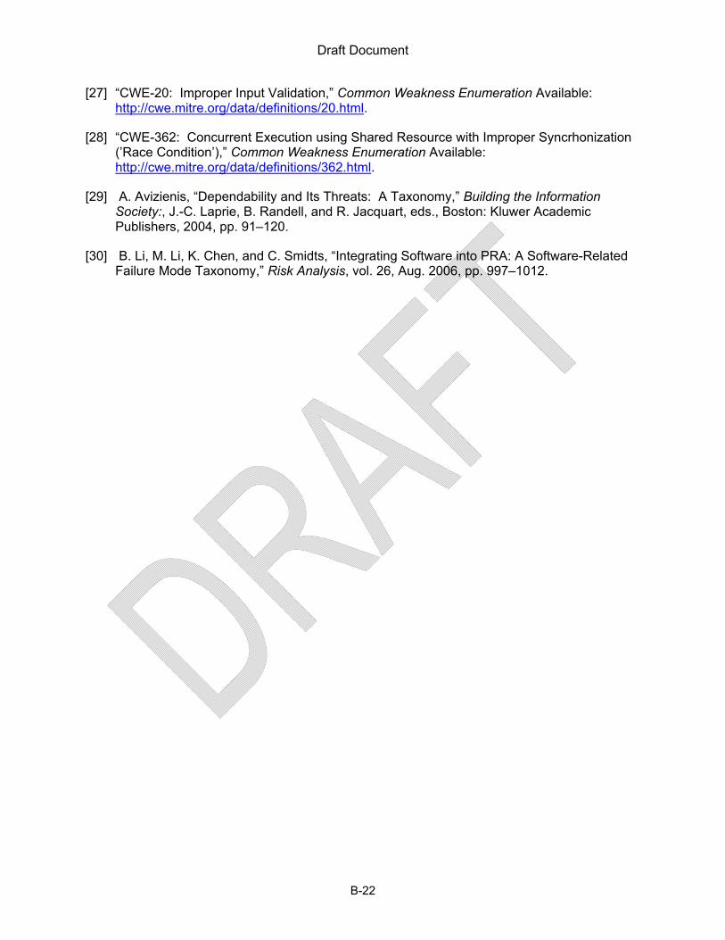
Draft Document
B-22
[27] “CWE-20: Improper Input Validation,” Common Weakness Enumeration Available: http://cwe.mitre.org/data/definitions/20.html.
[28] “CWE-362: Concurrent Execution using Shared Resource with Improper Syncrhonization (’Race Condition’),” Common Weakness Enumeration Available: http://cwe.mitre.org/data/definitions/362.html.
[29] A. Avizienis, “Dependability and Its Threats: A Taxonomy,” Building the Information Society:, J.-C. Laprie, B. Randell, and R. Jacquart, eds., Boston: Kluwer Academic Publishers, 2004, pp. 91–120.
[30] B. Li, M. Li, K. Chen, and C. Smidts, “Integrating Software into PRA: A Software-Related Failure Mode Taxonomy,” Risk Analysis, vol. 26, Aug. 2006, pp. 997–1012.
Draft Document
C-23
APPENDIX C. SOFTWARE FAULT MODES AND EFFECTS ANALYSIS METHODS
This appendix presents more details on staff findings on the efficacy of Software Fault59 Modes and Effects Analysis (SFMEA) as a method for identifying faults leading to system failures impairing a safety function. Although no accepted or proposed standards were found for SFMEA60, “companies have taken the traditional methods used for hardware and modified them for software” [9]. Methods that are based on Failure Modes and Effects Analysis (FMEA) are referred to as SFMEA and are documented in technical literature. Representative SFMEA processes and applications found in the literature are presented in this appendix. Observations on the similarities and differences are presented with conclusions pertinent to the efficacy of SFMEA as a method for identifying faults leading to system failures impairing a safety function.
C.1. SFMEA in Literature Reviewed
C.1.1. System and Detailed Level SFMEA
In his paper “Software FMEA Techniques” [10], Goddard described two types of SFMEA: System level and Detailed level SFMEA. Both techniques are described as being applied during system design stages.
System level is applied early in the software design after the architecture has been developed and functions have been assigned to separate software elements in the architecture. This analysis is focused on top level software design -- that is software elements are treated as black boxes, the code has not yet been written. The authors state that system level SFMEA should be updated as the top level software design progresses and in parallel with detailed design SFMEA.
Detailed SFMEA is applied late in the design process when, at minimum, pseudo code is available. Software requirements documentation, top level design descriptions, and detailed design descriptions should also be available. In performing the analysis, fault modes for each variable and each algorithm in each software element needs to be postulated. The effects of each postulated fault mode must them be traced through the code to the output signals. In both the article and his interview with NRC, [PG] stated that “detailed level SFMEA is becoming moot”61 because it is labor intensive. In particular, detailed SFMEA “may not be cost effective for systems with adequate hardware protections. [10]”
During his interview, [PG] stated that “the intent of the software FMEA is not to verify the quality of the software … the entire intent of the software FMEA is to demonstrate that should
59 Whereas the term, “failure modes and effects analysis (FMEA)” is used in the context of the overall DI&C system, the corresponding concept for software (and other forms of complex logic) in a DI&C system is “fault modes and effects analysis.” Logic does not fail in the traditional sense of degradation of a hardware component but the system could fail, due to a pre-existing logic fault, triggered by some combination of inputs and system-internal conditions.” [1]
60 The staff did find FMEA standards used for analysis of hardware that includes references: the following references to this footnote: [2],[3],[4],[5],[6],[7], and [8].
61 Tele-meeting between NRC and [PG] held on September 10, 2010.

Draft Document
C-24
something go wrong whether it’s hardware induced or software induced that the software architecture is such that it will catch that something went wrong and that it will handle it in a safe manner.” The important assumption is that it is possible to move to a safe state once something goes wrong. [PG] further noted that “showing that you can detect something, a discrepancy, is miles away from showing that you can isolate it correctly, make some kind of recovery technique and push forward.” There is no indication that the SFMEA methods in this reference are suitable for assurance or for identifying faults that lead to system failures impairing a safety function.
C.1.2. Functional, Interface, and Detailed SFMEA
Bowles and Wan built on the work of Goddard and provided an example of the SFMEA process applied to a ball-in-a-tube system in their paper “Software Failure Modes and Effect Analysis for a Small Embedded Control System” [11]. Bowles and Wan described three types of SFMEA: functional, interface, and detailed (compared to system and detailed SFMEA as described by Goddard [10]).
In performing the functional SFMEA, Bowles and Wan divided their program into four distinct software functions. The paper identified three fault modes each for two of the software functions and traced the effects of the fault modes (the local effect, next-level effect, and system effect). The local effect is the immediate consequence of the activated fault. The next-level effect is the consequence of the local effect. The system level effect is the failure that occurs at the system level. For example, the ball-in-tube system in this paper is designed to keep a small ball suspended at a predetermined height. Activated faults have local effects which lead to other effects which ultimately result in the system not being able to maintain the ball at the predetermined height.
For the interface SFMEA, Bowles and Wan identified three interfaces either between software modules or software-hardware elements of the system and provided four fault modes for one of the interfaces. For their example, local and system effects were identified for each of the four faults of one interface identified.
The detailed SFMEA was described as analyzing “the effect of individual software variable [faults] on the system output.” The paper listed faults applicable to a few possible variable types and provided a table example of detailed SFMEA for one computation used in their example system.
In this paper, Bowles and Wan caution that “detailed SFMEA can be most effectively applied to software for systems which do not have effective hardware memory protection, processing results protection, and memory transfer protection.” The SFMEA tables provided in Bowles’ and Wan’s paper include remarks suggesting that design changes are needed. There is no indication that the SFMEA methods in this reference are suitable for assurance or for identifying faults that lead to system failures impairing a safety function.
C.1.3. SFMEA for Requirements Analysis
Lutz and Woodhouse, in the paper “Experience Report: Contributions of SFMEA to Requirements Analysis”[12] describe their use of SFMEA process in combination with a process similar to Fault Tree Analysis (FTA) during the requirements analysis stage of the software lifecycle on twenty four software modules on two spacecraft systems. The SFMEA process is described as “forward searching to identify Cause/Effect relationships” in which data or software

Draft Document
C-25
behavior can result in unwanted effects. Fault modes were analyzed through two tables: A Data Table for analyzing communication faults (data read or received by the software process) and an Events Table to analyze software process faults (single actions such as “perform a calculation, sample a sensor value, and command an antenna to slew to another position”). The tables were used to identify concerns and vulnerable areas with sufficient detail so a reader could determine whether a requirement needed to be changed. Each table contained four columns. The data table columns consisted of: Data Item, Data Fault Type, Description, and Effect. The event table columns consisted of: Event, Event Fault Type, Description, and Effect. The data and event fault types are listed in Appendix B which discusses fault modes.
Lutz and Woodhouse noted that “like most failure analysis methods, SFMEA is time consuming; much of it is tedious; and it depends on the domain knowledge of the analyst and accuracy of the documentation” and that “unlike hardware, a complete list of failure modes for software cannot be assembled.” Despite the detractions, Lutz and Woodhouse “found that SFMEA was feasible and useful for requirements analysis in a large well-documented system.” There is no indication in this work that SFMEA is appropriate for assurance or for identifying faults leading to system failures impairing a safety function.
C.1.4. SFMEA for Model-Based and Object Oriented Environments
H. Hecht, in collaboration with X. An and M. Hecht, found SFMEA useful in model-based or object oriented design environments, specifically when Unified Modeling Language tools are used [13][14]. The approach is described for two lifecycle phases: concept and design/implementation. The authors also state that the techniques (with the aid of a computer) can be used to organize Verification and Validation activities. These authors stated that there are fundamentally “two approaches for partitioning software for a system FMEA: functional or by output variables, considering one variable at a time.” Both approaches are problematic because “functional partitions of a program are subjective and different analysts can come up with different lists of functions for a given program” and that “generating a software FMEA based on failures of a single output variable misses conditions in which a programming error affects multiple variables.” In light of these issues, Hecht et al, sought to automate the SFMEA process for use in the concept, design/implementation, and verification and validation (V&V) phases of the software lifecycle of model based or object oriented designed software.
The analysis process discussed in Hecht’s work is derived from MIL STD-1629 [4]. The SFMEA worksheet lists the following columns: ID, Component, Fault Mode62, Local Effect, Next-Higher-Level Effect, System Effect, Severity, Detection Method, Compensation, and Remarks. In this process, components are the methods of the object oriented structures in a software program. The Fault Modes used are a compressed set based on fault mode set provided in the STUK report [15] but others can be defined by the analyst. The analyst is also to provide the information for the compensation and remarks columns.
62 The article uses the column “Failure Mode.” The column heading was replaced for this appendix with “Fault Mode” for terminology consistency.

Draft Document
C-26
C.1.5. Code Level SFMEA
Nathaniel Ozarin in three papers: [16][17][18], argued that SFMEA is best performed at the code level (comparable to detail level as described by Goddard in [10]). He argued that “moving from the lowest level of analysis to the highest level – typically from the method level to the module or package level – a FMEA becomes less accurate, less precise, less tedious, and less time-consuming … a FMEA is based increasingly on the stated intent … and less on the actual product behavior”[16]. Ozarin used his technique to determine if a single software variable can cause catastrophic events or other serious effects. The result of his analysis is to make the source code “more robust in specific areas before deployment.” Ozarin provides no indication that SFMEA can be used to identify faults leading to system failures impairing a safety function.
The details of the process are articulated in reference [16] of this appendix. Ozarin specifically looks at situations where “a software variable is assigned an unintended value” and follows six steps for the SFMEA process. The six steps are:
1) System and Software Familiarization 2) Database Tool Development 3) Developing Rules and Assumptions 4) Developing Descriptive [Fault]63 Modes 5) Determining System Effects of Individual [Faults] 64 6) Generating the Report
The system and software familiarization is the first step because he recommends that SFMEA “should not be performed by the people who developed the code. The purpose of the database tool development stage is to develop tables to organize the information obtained through the SFMEA process. The proposed tables include a table to organize the different parts of the software program (for example classes could be considered parts of the program). A second table defines the functions of each subroutine. The third table lists the appropriate variables (both input and output). A third table organizes the input and output variables of the program. In step four rules and assumptions are outlined for performing the analysis. In step 5 fault modes are developed that specify how a variable can take on a value that negatively affects the subroutines that use the variable. The effects of each fault are considered in step 5. In step 6, the findings and conclusions of the analysis are presented in report format.
C.1.6. Automated Code Level SFMEA
Snooke et al., through references [20], [21], [22], [23], has explored automating his version of a SFMEA process. Snooke’s work stems from the observation that “code level software FMEA has been performed for some years, but has been considered impractical except when applied to small pieces of highly critical code” [22]. Snooke proposes a three step process. The first step is that “the source code of the software to be analyzed [be] parsed and transformed into a fault propagation model” [22]. The second step involves injection and propagation of faulty input
63 The word used in the reference is “failure.” It was replaced in this appendix for consistency based on the definitions provided in the Glossary.
64 The word used in the reference is “failure.” It was replaced in this appendix for consistency based on the definitions provided in the Glossary.

Draft Document
C-27
and output variables. The third step is identification of system level effects by mapping the functions of the software program to variables that implement the functions. Snooke notes that “this work is clearly program language dependent … model construction has been achieved for a large subset of the JAVA language.” Furthermore, the work he describes “does not cover all constructs in all languages.” Snooke states that other tools and processes could be used to make modifications after performance of an SFMEA [23]. Snooke also writes that “generally the response might be to identify and remove unintended interactions and improve error checking” [23].
C.1.7. Other Versions of the SFMEA Process
A few other sources were found describing a SFMEA process (See [24],[25],[26],[27]). These are not discussed to the extent of the examples above because they contained no new information. Reference [24] provided an example of SFMEA for an object oriented software framework that utilized a block diagram of the code to develop a list of possible fault modes which would be traced from lower level effects up to system level effects. Reference [25] “did not involve a detailed analysis of the software.” The process used in [26] is similar to Goddard’s work [10]. Park et al, in “Software FMEA Analysis for Safety Software” [27], used SFMEA to analyze an Automatic Test and Interface Processor for a reactor protection system. Details about the process used in [27] were not provided. The article did state that function blocks were used to represent the code and that the fault modes considered fell under functional, input, and output categories. The process, as described, in [27] has elements of the detailed process descriptions provided in this appendix. Other non-public documents were also reviewed but are not discussed. No new information was obtained in these non-public documents.
C.1.8. Similarities and Differences among Sources Cited
Each of the versions of the “SFMEA” process found shared some similarities but also had some differences. All of the examples describe a process where the software is broken down into more manageable parts for analysis, they evaluated fault modes (see Appendix B for a listing of the fault modes found), and traced the effects of activating those fault modes. The level of abstraction of the software considered was different and ranged from very high level (e.g,, system-level, functional) to more detailed (e.g., code level, interface level). The extent to which the effects were traced also differed. The software lifecycle stages in which the SFMEA process was applied ranged from the requirements stage to late in the design stage. The processes described all had limitations to specific software languages, design environments, or were not to be used under certain conditions (such as software systems with memory protection [10].
C.2. Efficacy of SFMEA in Identifying Faults
The staff acknowledges that the variations of the SFMEA process reviewed have been useful in various stages of the software lifecycle65; however, the staff also found that:
65 The methods described in this appendix indicate that SFMEA was useful to the authors and practitioners during software design.

Draft Document
C-28
• The potential fault space in software of moderate complexity is large [1]. Many faults and fault propagation paths are difficult to identify because “may be masked by some other functionality.” [JM].66
• No standard process for performing an SFMEA was found. The variations of the SFMEA process reviewed were not applicable to all coding languages or software systems.
• It is difficult to consider all the possible effects of any identified fault on the system. That is, analysis of a fault mode may not provide certainty that any system will fail in any particular way because the effects can depend on time or situation dependent conditions that may apply only under very specific circumstances.
• The techniques reviewed do not identify faults resulting from system-system and system-environment interactions [19]67
In summary, for moderately complex software, SFMEA is not suitable for identifying all faults leading to system failures impairing a safety function. Thus, the contribution of the reviewed SFMEA techniques towards assurance of software would be marginal.
C.3. Bibliography
[1] L. Betancourt, S. Birla, J. Gassino, and P. Regnier, “Suitability of Fault Modes and Effects Analysis for Regulatory Assurance of Complex Logic in Digital Instrumentation and Control Systems,” Nuclear Regulatory Commission, NUREG/IA-0254, Apr. 2011.
[2] International Electrotechnical Commission, Analysis techniques for system reliability: procedure for failure mode and effects analysis (FMEA). Geneva: International Electrotechnical Commission, 2006.
[3] SAE, “SAE J1739, Potential Failure Mode and Effects Analysis in Design (Design FMEA), Potential Failure Mode and Effects Analysis in Manufacturing and Assembly Processes (Process FMEA),” SAE International, Standard J1739, Jan. 2009.
[4] “Military Standard: Procedures for Performing a Failure Mode, Effects and Cirticality Analysis,” U.S. Department of Defense, MIL-STD-1629A, Nov. 1980.
[5] SAE, “SAE ARP 5580, Recommended Failure Modes and Effects Analysis (FMEA) Practices for Non-Automotive Applications,” Standard SAE ARP 5580, 2001.
[6] Chrysler Corporation, Ford Motor Company, General Motors Corporation, and Automotive Industry Action Group, Potential failure mode and effects analysis (FMEA): reference manual. [Southfield, MI]: Chrysler LLC, Ford Motor Co., General Motors Corp., 2008.
66 See Appendix B for a list of faults and fault modes identified during the expert elicitation process and in the technical literature reviewed.
67 EPRI Report Number 3002000509 “Hazard Analysis Methods for Digital Instrumentation and Control Systems.” published in June 2013 also includes this conclusion.

Draft Document
C-29
[7] “352-1987: IEEE Guide for General Principles of Reliability Analysis of Nuclear Power Generating Station Safety Systems,” ANSI/IEEE, 1987.
[8] British Standards Institution Group, BS EN 60812:2006 Analysis techniques for system reliability. Procedure for Failure Mode and Effects Analysis (FMEA). British Standards Institution Group, 2006.
[9] N. Bidokhti, “How FMEA Improves Hardware and Software Safety & Design Reuse,” presented at the International Workshop on Software Reuse and Safety (RESAFE-2006), Torino, Italy, 2011.
[10] P. L. Goddard, “Software FMEA Techniques,” 2000, pp. 118–123.
[11] J. B. Bowles and C. Wan, “Software failure modes and effects analysis for a small embedded control system,” 2011, pp. 1–6.
[12] R. R. Lutz and R. M. Woodhouse, “Experience Report: Contributions of SFMEA to Requirements Analysis,” in ICRE, 1996, pp. 44–51.
[13] H. Hecht, Xuegao An, and M. Hecht, “Computer aided software FMEA for unified modeling language based software,” pp. 243–248.
[14] H. Hecht, X. An, and M. Hecht, “More Effective V&V By Use of Software FMEA.”
[15] P. Haapanen, Failure mode and effects analysis of software-based automation systems. Helsinki: Radiation and Nuclear Safety Authority, 2002.
[16] N. Ozarin, “Failure modes and effects analysis during design of computer software,” 2011, pp. 201–206.
[17] N. Ozarin and M. Siracusa, “A process for failure modes and effects analysis of computer software,” presented at the Reliability and Maintainability Symposium, 2003. Annual, 2003, pp. 365–370.
[19] Song, Yao, "Applying System-Theoretic Accident Model and Processes (STAMP) to
Hazard Analysis" (2012). Open Access Dissertations and Theses. Paper 6801. Available: http://digitalcommons.mcmaster.ca/cgi/viewcontent.cgi?article=7836&context=opendissertations
[18] N. Ozarin, “The Role of Software Failure Modes and Effects Analysis for Interfaces in Safety- and Mission-Critical Systems,” presented at the SysCon 2008-IEEE International Systems Conference, Montreal, Canada, 2008.
[20] C. Price and N. Snooke, “An Automated Software FMEA,” Singapore, 2008.
[21] N. Snooke and J. Bell, “Combining Functional Modelling and Qualitative Fault Propagation to Enable Faiure Mode Effects Analysis of Software Systems,” presented at the ECAI MONET workshop, Riva, Italy, 2006.
[22] N. Snooke and C. Price, “Model-driven automated software FMEA,” 2011, pp. 1–6.

Draft Document
C-30
[23] N. Snooke, “Model-based Failure Modes and Effects Analysis of Software.”
[24] Tadeusz Cichocki; Janusz Gorski, “Failure Mode and Effect Analysis for Safety-Critical Systems with Software Components,” presented at the 19th International Conference, SAFECOMP 2000, Rotterdam, the Netherlands, 2000.
[25] T.-L. Chu, M. Yue, G. Martinez-, and J. Lehner, “A Generic Failure Modes and Effects Analysis (FMEA) Approach for Reliability Modeling of Digital Instrumentation and Control (I&C) Systems,” presented at the 10th International Probabilistic Safety Assessment and Management Conference, Seattle, Washington, 2010.
[26] B. J. Czerny, J. G. D’Ambrosio, B. T. Murray, and P. Sundaram, “Effective Application of Software Safety Techniques for Automotive Embedded Control Systems,” SAE International, Warrendale, PA, 2005-01-0785, Apr. 2005.
[27] G.-Y. Park, “Software FMEA Analysis for Safety Software,” presented at the International Conference on Nuclear Engineering, Brussels, Belgium.

Draft Document
D-1
APPENDIX D. OPERATING EXPERIENCE AND FAILURE MODES
This appendix discusses practice in the organization of operating experience for a “traditional68” electromechanical device, a 3-phase AC, squirrel cage induction motor, and suitability of a similar approach for complex software.
D.1. Failure Modes of Induction Motors: Example usage
Three-phase AC squirrel cage induction motors vary over a wide range in combinations of size, power, and speed, but the engineering principles and key functional elements are the same, namely:
1. Stator; stator winding 2. Rotor; armature 3. Casing or Housing 4. Shaft 5. Bearings
Because the functional elements are the same across the whole range of motors, the associated failure mechanisms are the same, and their effect on the behavior of the whole motor is the same; thus, a compact, complete set of well-defined failure modes that apply to all squirrel cage induction motors can be identified. The following failure69 modes are from the Chapter 14 of the Handbook of Reliability Prediction Procedures for Mechanical Equipment on the US Navy’s Naval Sea System Command website [1]:
1. Open winding 2. Shorted winding 3. Worn bearing; worn sleeve bearing 4. Cracked Housing 5. Sheared (armature) shaft 6. Cracked rotor laminations 7. Worn brushes (applicable to a DC motor with brushes; not applicable to an induction
motor)
Yet, Operating-experience data for the specific failure modes listed above was not found. A literature search revealed that frequency of failure data is most often organized by component. This organization was found useful, because the key functional elements, their failure mechanisms, the dominant, failure modes manifested at the motor-level remained the same for all 3-phase AC, squirrel cage induction motors. The underlying reasons are (1) The same engineered principles and key functional elements are used in all these motors, and (2) their dominant conditions of use fall in the same general pattern.
For example, data for large (200 hp) motors can be found in the IEEE Recommended Practice for the Design of Reliable Industrial and Commercial Power Systems (IEEE Std 493-1997) [2]. Specifically, Table 3-17 presents the raw number of failures for each component, and Table 3-
68 Characterized by long-term stability in engineering principles and design realizations.
69 Note: Usage of the term, failure mode, across guidance documents is not consistent with the definition selected in RIL-1002. In this case, it is mixed up with failure mechanisms.

Draft Document
D-2
19 presents the percentage of failures that pertain to failure initiators, failure contributors, and underlying causes.
D.2. Digital System Failure Modes: Utility in organizing operating experience data
Digital safety systems emerging in NPPs are complex, the underlying engineering, design, and implementation paradigms vary widely, and even for similar systems, conditions of use are sufficiently different to challenge meaningful aggregation and organization of data from operating experience according to system level failure modes such as those characterized in Section 5.1. Furthermore, when a system failure is caused by software or by some other systemic factor, “part replacement” (as in traditional electromechanical devices) does not correct the problem. The cause has to be removed or corrected; then, it is not the same system anymore. Aggregation of failure data across such changes would not support meaningful analysis as simply as it does for replaced parts.
D.3. Bibliography
[1] Naval Surface Warfare Center Carderock Division, “Chapter 14: Electric Motors,” Handbook of Reliability Prediction Procedures for Mechanical Equipment, 2011 Available: http://www.navsea.navy.mil/nswc/carderock/pub/mechrel/products/handbook.aspx.
[2] IEEE, 493-1997 (Gold Book), 1998 Available: http://ieeexplore.ieee.org/lpdocs/epic03/wrapper.htm?arnumber=757619

Draft Document
E-1
APPENDIX E. FAILURE MODE RELATED EFFORTS BY NRC PRA STAFF AND OTHER STAKEHOLDERS
There is additional work related to identification of digital safety system failure modes that is directly sponsored by the NRC, indirectly sponsored through NRC international collaborative efforts70, or sponsored by other stakeholders with interests in the Nuclear Industry. These efforts are ongoing and are not expected to impact or change the results presented in this RIL. A summary of these efforts is presented in this appendix.
E.1. Probabilistic Risk Assessment Research
As described in the background of this RIL, the Commission, through its 1995 PRA Policy Statement, has encouraged the use of PRA technology in all regulatory matters to the extent supported by the state of the art in PRA methods and data. Because there is no consensus on how to quantify the reliability of digital systems, the NRC is performing research on the development of probabilistic models for digital I&C for inclusion in Nuclear Power Plant (NPP) Probabilistic Risk Assessments (PRAs).
Brookhaven National Laboratory (BNL) is supporting the NRC in this research through a series of projects on digital I&C system reliability modeling and quantification. Previous BNL projects have focused on reliability modeling and quantification of digital system hardware and on a review of available quantitative software reliability methods (QSRMs) that can be used to quantify software failure rates and probabilities of digital systems at NPPs. In addition, this previous work involved identification of a set of desirable characteristics for QSRMs. In current work, two candidate QSRMs have been selected based on a structured comparison of the previously-identified QSRMs against the set of identified desirable characteristics for further investigation through a case study.
The PRA/BNL Research is different and separate from the digital I&C systems work presented in RILs 1001-1003 and NUREG/IA-0254. While these two areas of research (i.e., digital I&C PRA and analytical assessment of digital I&C systems) are closely related in many ways, it should be emphasized that they are intended to support very different applications. The research in the body of this RIL is focused towards assurance of safety critical digital systems while the PRA research is focused on quantifying failures caused by software in terms of failure rates and probabilities. As such, conclusions about the methods discussed in RIL-1002 may or may not be appropriate for the intent of the PRA research and vice versa.71
70 The staff has also been exposed to relevant information through presentations at conferences and other meetings with experts from other organizations interested in the digital safety systems. These other organizations include NASA, Society of Automotive Engineers, etc.
71 PRA experts in the RES staff have indicated that the failure modes, faults, and fault modes, and SFMEA approaches discussed in this RIL may have potential uses for PRA applications. Staff working on both the PRA related failure mode research and failure mode research for safety assurance are coordinating to ensure technical consistency between the two efforts.

Draft Document
E-2
E.2. Working Group on Risk Assessment (WGRisk) Activities and Results
The US government actively participates in Organisation for Economic Co-operation and Development (OECD) activities. The NRC specifically collaborates through the Nuclear Energy Agency (NEA), which is a specialized agency within OECD [1]. The Committee on the Safety of Nuclear Installations (CSNI), which is a committee under the NEA [2] created and directed the Working Group on Risk Assessment to set up a task group to coordinate an activity on DI&C system risk. The NRC joined this effort to complement the work previously described in Section C.1 above.
One workshop has been held and two others are scheduled72 to discuss and share experiences with modeling and quantifying NPP DI&C systems in a PRA context. A resulting action from this interaction has been to develop a taxonomy of failure modes of digital components for the purposes of performing PRA.73 Preliminary work has been done to create the taxonomy but this work is not complete or publically available, however, some papers based on the work have been presented at the Probabilistic Safety Assessment International Conference (PSAM 11, 2012) in Helsinki.
Relevant failure modes identified in these published papers are in Table 10, Failure Mode Set J - Summary of failure mode taxonomies,” in Section 5.1.1.10. Relevant fault modes are located in Appendix B. The failure and fault mode examples provided for Failure Mode Set J and Fault Mode Set 10 are from the following ten organizations:
• Brookhaven National Laboratory (BNL) • Canadian Nuclear Safety Commission (CNSC) • Electricity of France (EDF) • Institut de Radioprotection et de Suerte Nucleaire (IRSN) • Japan Nuclear Energy Safety Organization (JNES) • Korean Atomic Energy Research Institute (KAERI) • Nuclear Research and Consultancy Group (NRG) • Nordic Nuclear Energy Research (NKS) • Ohio State University (OSU) • Technical Research Centre of Finland (VTT)
E.3. Halden Research Project Efforts
The NRC actively collaborates with the Halden Reactor Project (HRP)74 in Norway on topics of mutual interest.75 The staff regularly attends meetings organized by the HRP that update all stakeholders on ongoing research projects and closely related research by other organizations.
At the most recent meeting held on October 1-7, 2011, at Sandefjord, Norway, NRC staff attended a presentation of ongoing research on cost-efficient methods and processes for safety
72 As of this writing. 73 Note that the WGRisk Group has not adopted the terminology used in this RIL. Their efforts are producing both failure modes and fault modes. 74 Like the WGRisk Group, the HRP is also operates under the auspices of OECD’s NEA. 75 The U.S. has participated (and been one source of funding) in the Halden Research Project since 1958.

Draft Document
E-3
relevant embedded systems (CESAR)76 [3], which contained information relevant to SRM M080605B and the recommendations resulting from the ACRS 576th meeting (October 20,2010). Relevant information from this interaction is presented in the main body of this RIL.
E.4. References
[1] NEA, “The Nuclear Energy Agency Website,” Organisation for Economic Co-Operation and Development Nuclear Energy Agency Available: http://www.oecd-nea.org/nea/
[2] NEA/CSNI, “Committee on the Safety of Nuclear Installations (CSNI) Webpage,” Committee on the Safety of Nuclear Installations Available: http://www.oecd-nea.org/nsd/csni/
[3] CESAR/ARTEMIS Joint Undertaking, “Cost Efficient Methods and Processes for Safety Relevant Embedded Systems,” CESAR Project Available: http://www.cesarproject.eu/
76 CESAR is a European project funded under the ARTEMIS Joint Undertaking. See references for more information
Related Documents


