Identification of dynamic and friction parameters of a parallel manipulator with actuation redundancy Weiwei Shang a, * , Shuang Cong a , Fanrang Kong b a Department of Automation, University of Science and Technology of China, Hefei, Anhui 230027, PR China b Department of Precision Machinery and Precision Instrumentation, University of Science and Technology of China, Hefei, Anhui 230027, PR China article info Article history: Received 26 May 2009 Accepted 23 November 2009 Available online xxxx Keywords: Parallel manipulator Actuation redundancy Parameter identification Dynamics Friction abstract The dynamic model is formulated in the joint space for a parallel manipulator with actuation redundancy. The established model is expressed in its linear matrix form with respect to the dynamic and friction parameters, and then the Weighted Least Square (WLS) method is applied to estimate the parameters. In order to get satisfying estimated results, the filters of joint angle and actuated torque are designed for the parallel manipulator. A simple and effective method is presented to design the excitation trajec- tory by analyzing the mechanism structure characteristics of the actual parallel manipulator. Another type of trajectory which is different from the excitation trajectory is adopted to verify the estimated parameters. The dynamic control experiments based on the identified model with the estimated param- eters are implemented on an actual 2-DOF parallel manipulator with actuation redundancy, and the tracking accuracy of the identified model is compared with the result of the so-called nominal model. Ó 2009 Elsevier Ltd. All rights reserved. 1. Introduction There are two or more kinematic chains in the mechanism structure of the parallel manipulators. The coordination manipula- tion of the end-effector with the multiple kinematic chains can de- crease the cumulative error, and make parallel manipulators have advantages such as high-speed and high load capacity [1]. Parallel manipulators constitute an important complementary relationship with the serial manipulators in mechanism structure and practical application, thus the application fields of the robotic manipulators are expanded. With the development of robotic technology and application, the requirement of the performances of the robotic manipulators has become higher, thus the parallel manipulators with actuation redundancy are designed [2]. The redundant actua- tion can eliminate the actuator singularity [3], optimize the actua- tor torque [4], and make up the impact of the actuator fault [5], so the efficiency and reliability of the parallel manipulators can be further improved. In order to realize the above potential perfor- mances of the parallel manipulators with actuation redundancy in the motion control, the dynamic model based controllers should be designed, and the accurate dynamic model must be formulated firstly. The dynamic model which depicts the relation between the tra- jectory and the torque is the basis of solving the forward dynamics and inverse dynamics. Simulation and control of parallel manipu- lators call for corresponding forward dynamics and inverse dynam- ics [6]. There are large numbers of references about dynamic modeling of the parallel manipulators. The dynamic modeling methods of parallel manipulators come from the traditional robot- ics. Several standard approaches have been used to establish the dynamic model, including the Newton–Euler formulation [7,8], Lagrangian formulation [9–11], and the principle of virtual work [12,13]. The analysis and comparison of the above approaches have been studied by Sokolov and Xirouchakis in [14]. The basic theory of these approaches can be found in the classical books about the robotics [15,16]. While the structure of the dynamic model equa- tions of a parallel manipulator can be formulated with the above approaches, the accurate values of the model parameters are not always available for the following reasons. On one hand, the phys- ical parameters such as mass, length, and inertia provided by man- ufacturers are often inconsistent, thus the dynamic parameters calculated by the above physical parameters are inaccurate [17]. Furthermore, the values of the dynamic parameters may be vari- able after long running. On the other hand, the friction parameters in the dynamic model cannot be measured directly, and they must be estimated by the actual experiments. As a result, experimental identification of the dynamic parameters and friction parameters is indispensable to develop the actual dynamic model for a parallel manipulator. In contrast to the vast literature concerning the identification of serial manipulators, actually, there are only a few publications dealing with the simultaneous identification of the dynamic and friction parameters of parallel manipulators, especially those with 0957-4158/$ - see front matter Ó 2009 Elsevier Ltd. All rights reserved. doi:10.1016/j.mechatronics.2009.11.005 * Corresponding author. Tel.: +86 551 3607149; fax: +86 551 3603244. E-mail address: [email protected] (W. Shang). Mechatronics xxx (2009) xxx–xxx Contents lists available at ScienceDirect Mechatronics journal homepage: www.elsevier.com/locate/mechatronics ARTICLE IN PRESS Please cite this article in press as: Shang W et al. Identification of dynamic and friction parameters of a parallel manipulator with actuation redundancy. Mechatronics (2009), doi:10.1016/j.mechatronics.2009.11.005

Welcome message from author
This document is posted to help you gain knowledge. Please leave a comment to let me know what you think about it! Share it to your friends and learn new things together.
Transcript
Mechatronics xxx (2009) xxx–xxx
ARTICLE IN PRESS
Contents lists available at ScienceDirect
Mechatronics
journal homepage: www.elsevier .com/ locate/mechatronics
Identification of dynamic and friction parameters of a parallel manipulatorwith actuation redundancy
Weiwei Shang a,*, Shuang Cong a, Fanrang Kong b
a Department of Automation, University of Science and Technology of China, Hefei, Anhui 230027, PR Chinab Department of Precision Machinery and Precision Instrumentation, University of Science and Technology of China, Hefei, Anhui 230027, PR China
a r t i c l e i n f o
Article history:Received 26 May 2009Accepted 23 November 2009Available online xxxx
Keywords:Parallel manipulatorActuation redundancyParameter identificationDynamicsFriction
0957-4158/$ - see front matter � 2009 Elsevier Ltd. Adoi:10.1016/j.mechatronics.2009.11.005
* Corresponding author. Tel.: +86 551 3607149; faxE-mail address: [email protected] (W. Shang)
Please cite this article in press as: Shang W et aMechatronics (2009), doi:10.1016/j.mechatroni
a b s t r a c t
The dynamic model is formulated in the joint space for a parallel manipulator with actuation redundancy.The established model is expressed in its linear matrix form with respect to the dynamic and frictionparameters, and then the Weighted Least Square (WLS) method is applied to estimate the parameters.In order to get satisfying estimated results, the filters of joint angle and actuated torque are designedfor the parallel manipulator. A simple and effective method is presented to design the excitation trajec-tory by analyzing the mechanism structure characteristics of the actual parallel manipulator. Anothertype of trajectory which is different from the excitation trajectory is adopted to verify the estimatedparameters. The dynamic control experiments based on the identified model with the estimated param-eters are implemented on an actual 2-DOF parallel manipulator with actuation redundancy, and thetracking accuracy of the identified model is compared with the result of the so-called nominal model.
� 2009 Elsevier Ltd. All rights reserved.
1. Introduction
There are two or more kinematic chains in the mechanismstructure of the parallel manipulators. The coordination manipula-tion of the end-effector with the multiple kinematic chains can de-crease the cumulative error, and make parallel manipulators haveadvantages such as high-speed and high load capacity [1]. Parallelmanipulators constitute an important complementary relationshipwith the serial manipulators in mechanism structure and practicalapplication, thus the application fields of the robotic manipulatorsare expanded. With the development of robotic technology andapplication, the requirement of the performances of the roboticmanipulators has become higher, thus the parallel manipulatorswith actuation redundancy are designed [2]. The redundant actua-tion can eliminate the actuator singularity [3], optimize the actua-tor torque [4], and make up the impact of the actuator fault [5], sothe efficiency and reliability of the parallel manipulators can befurther improved. In order to realize the above potential perfor-mances of the parallel manipulators with actuation redundancyin the motion control, the dynamic model based controllers shouldbe designed, and the accurate dynamic model must be formulatedfirstly.
The dynamic model which depicts the relation between the tra-jectory and the torque is the basis of solving the forward dynamicsand inverse dynamics. Simulation and control of parallel manipu-
ll rights reserved.
: +86 551 3603244..
l. Identification of dynamic andcs.2009.11.005
lators call for corresponding forward dynamics and inverse dynam-ics [6]. There are large numbers of references about dynamicmodeling of the parallel manipulators. The dynamic modelingmethods of parallel manipulators come from the traditional robot-ics. Several standard approaches have been used to establish thedynamic model, including the Newton–Euler formulation [7,8],Lagrangian formulation [9–11], and the principle of virtual work[12,13]. The analysis and comparison of the above approaches havebeen studied by Sokolov and Xirouchakis in [14]. The basic theoryof these approaches can be found in the classical books about therobotics [15,16]. While the structure of the dynamic model equa-tions of a parallel manipulator can be formulated with the aboveapproaches, the accurate values of the model parameters are notalways available for the following reasons. On one hand, the phys-ical parameters such as mass, length, and inertia provided by man-ufacturers are often inconsistent, thus the dynamic parameterscalculated by the above physical parameters are inaccurate [17].Furthermore, the values of the dynamic parameters may be vari-able after long running. On the other hand, the friction parametersin the dynamic model cannot be measured directly, and they mustbe estimated by the actual experiments. As a result, experimentalidentification of the dynamic parameters and friction parametersis indispensable to develop the actual dynamic model for a parallelmanipulator.
In contrast to the vast literature concerning the identification ofserial manipulators, actually, there are only a few publicationsdealing with the simultaneous identification of the dynamic andfriction parameters of parallel manipulators, especially those with
friction parameters of a parallel manipulator with actuation redundancy.
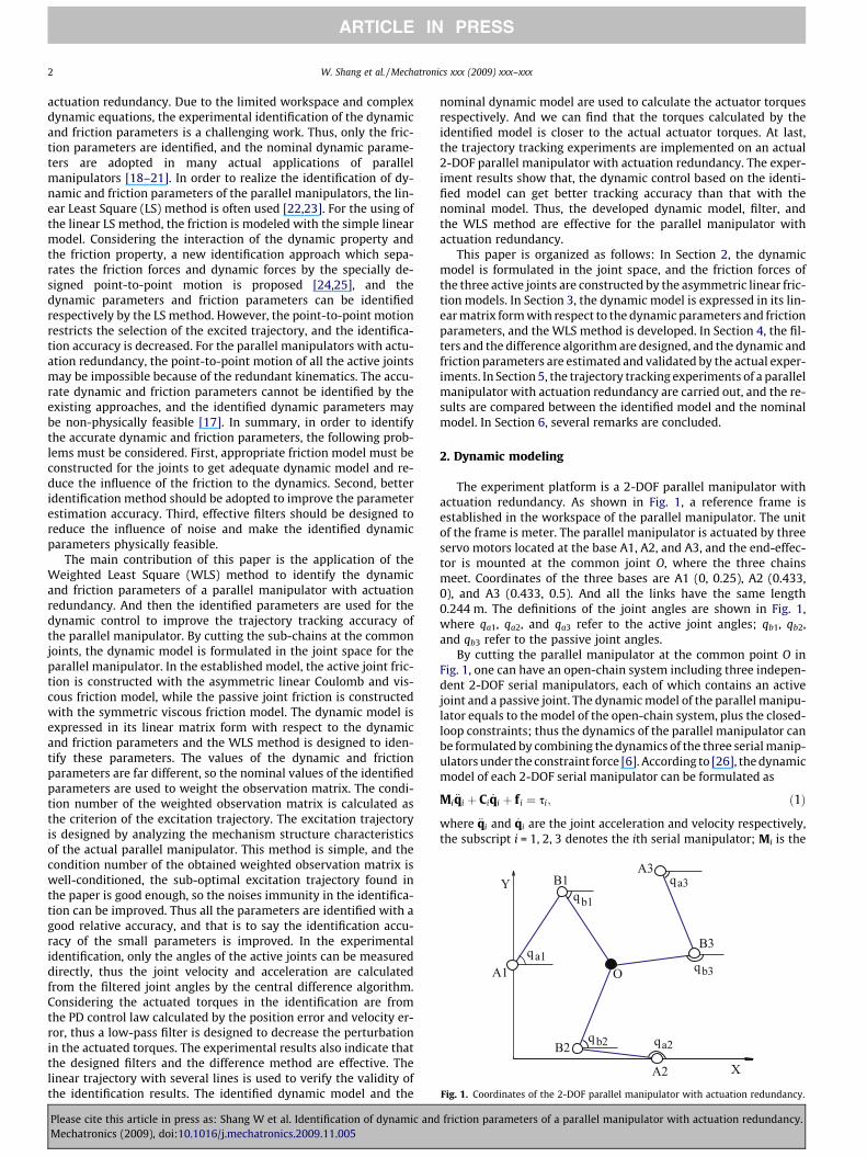
Fig. 1. Coordinates of the 2-DOF parallel manipulator with actuation redundancy.
2 W. Shang et al. / Mechatronics xxx (2009) xxx–xxx
ARTICLE IN PRESS
actuation redundancy. Due to the limited workspace and complexdynamic equations, the experimental identification of the dynamicand friction parameters is a challenging work. Thus, only the fric-tion parameters are identified, and the nominal dynamic parame-ters are adopted in many actual applications of parallelmanipulators [18–21]. In order to realize the identification of dy-namic and friction parameters of the parallel manipulators, the lin-ear Least Square (LS) method is often used [22,23]. For the using ofthe linear LS method, the friction is modeled with the simple linearmodel. Considering the interaction of the dynamic property andthe friction property, a new identification approach which sepa-rates the friction forces and dynamic forces by the specially de-signed point-to-point motion is proposed [24,25], and thedynamic parameters and friction parameters can be identifiedrespectively by the LS method. However, the point-to-point motionrestricts the selection of the excited trajectory, and the identifica-tion accuracy is decreased. For the parallel manipulators with actu-ation redundancy, the point-to-point motion of all the active jointsmay be impossible because of the redundant kinematics. The accu-rate dynamic and friction parameters cannot be identified by theexisting approaches, and the identified dynamic parameters maybe non-physically feasible [17]. In summary, in order to identifythe accurate dynamic and friction parameters, the following prob-lems must be considered. First, appropriate friction model must beconstructed for the joints to get adequate dynamic model and re-duce the influence of the friction to the dynamics. Second, betteridentification method should be adopted to improve the parameterestimation accuracy. Third, effective filters should be designed toreduce the influence of noise and make the identified dynamicparameters physically feasible.
The main contribution of this paper is the application of theWeighted Least Square (WLS) method to identify the dynamicand friction parameters of a parallel manipulator with actuationredundancy. And then the identified parameters are used for thedynamic control to improve the trajectory tracking accuracy ofthe parallel manipulator. By cutting the sub-chains at the commonjoints, the dynamic model is formulated in the joint space for theparallel manipulator. In the established model, the active joint fric-tion is constructed with the asymmetric linear Coulomb and vis-cous friction model, while the passive joint friction is constructedwith the symmetric viscous friction model. The dynamic model isexpressed in its linear matrix form with respect to the dynamicand friction parameters and the WLS method is designed to iden-tify these parameters. The values of the dynamic and frictionparameters are far different, so the nominal values of the identifiedparameters are used to weight the observation matrix. The condi-tion number of the weighted observation matrix is calculated asthe criterion of the excitation trajectory. The excitation trajectoryis designed by analyzing the mechanism structure characteristicsof the actual parallel manipulator. This method is simple, and thecondition number of the obtained weighted observation matrix iswell-conditioned, the sub-optimal excitation trajectory found inthe paper is good enough, so the noises immunity in the identifica-tion can be improved. Thus all the parameters are identified with agood relative accuracy, and that is to say the identification accu-racy of the small parameters is improved. In the experimentalidentification, only the angles of the active joints can be measureddirectly, thus the joint velocity and acceleration are calculatedfrom the filtered joint angles by the central difference algorithm.Considering the actuated torques in the identification are fromthe PD control law calculated by the position error and velocity er-ror, thus a low-pass filter is designed to decrease the perturbationin the actuated torques. The experimental results also indicate thatthe designed filters and the difference method are effective. Thelinear trajectory with several lines is used to verify the validity ofthe identification results. The identified dynamic model and the
Please cite this article in press as: Shang W et al. Identification of dynamic andMechatronics (2009), doi:10.1016/j.mechatronics.2009.11.005
nominal dynamic model are used to calculate the actuator torquesrespectively. And we can find that the torques calculated by theidentified model is closer to the actual actuator torques. At last,the trajectory tracking experiments are implemented on an actual2-DOF parallel manipulator with actuation redundancy. The exper-iment results show that, the dynamic control based on the identi-fied model can get better tracking accuracy than that with thenominal model. Thus, the developed dynamic model, filter, andthe WLS method are effective for the parallel manipulator withactuation redundancy.
This paper is organized as follows: In Section 2, the dynamicmodel is formulated in the joint space, and the friction forces ofthe three active joints are constructed by the asymmetric linear fric-tion models. In Section 3, the dynamic model is expressed in its lin-ear matrix form with respect to the dynamic parameters and frictionparameters, and the WLS method is developed. In Section 4, the fil-ters and the difference algorithm are designed, and the dynamic andfriction parameters are estimated and validated by the actual exper-iments. In Section 5, the trajectory tracking experiments of a parallelmanipulator with actuation redundancy are carried out, and the re-sults are compared between the identified model and the nominalmodel. In Section 6, several remarks are concluded.
2. Dynamic modeling
The experiment platform is a 2-DOF parallel manipulator withactuation redundancy. As shown in Fig. 1, a reference frame isestablished in the workspace of the parallel manipulator. The unitof the frame is meter. The parallel manipulator is actuated by threeservo motors located at the base A1, A2, and A3, and the end-effec-tor is mounted at the common joint O, where the three chainsmeet. Coordinates of the three bases are A1 (0, 0.25), A2 (0.433,0), and A3 (0.433, 0.5). And all the links have the same length0.244 m. The definitions of the joint angles are shown in Fig. 1,where qa1, qa2, and qa3 refer to the active joint angles; qb1, qb2,and qb3 refer to the passive joint angles.
By cutting the parallel manipulator at the common point O inFig. 1, one can have an open-chain system including three indepen-dent 2-DOF serial manipulators, each of which contains an activejoint and a passive joint. The dynamic model of the parallel manipu-lator equals to the model of the open-chain system, plus the closed-loop constraints; thus the dynamics of the parallel manipulator canbe formulated by combining the dynamics of the three serial manip-ulators under the constraint force [6]. According to [26], the dynamicmodel of each 2-DOF serial manipulator can be formulated as
Mi €qi þ Ci _qi þ f i ¼ si; ð1Þ
where €qi and _qi are the joint acceleration and velocity respectively,the subscript i = 1, 2, 3 denotes the ith serial manipulator; Mi is the
friction parameters of a parallel manipulator with actuation redundancy.
W. Shang et al. / Mechatronics xxx (2009) xxx–xxx 3
ARTICLE IN PRESS
inertia matrix, and Ci is the Coriolis and centrifugal force matrix,which can be defined as
Mi ¼ai ci cosðqai � qbiÞ
ci cosðqai � qbiÞ bi
� �;
Ci ¼0 ci sinðqai � qbiÞ _qbi
�ci sinðqai � qbiÞ _qai 0
� �;
where ai, bi, and ci are the dynamic parameters. These parametersare related with the physical parameters, and they are difficult tobe measured accurately. Also, si ¼ sai sbi½ �T is the joint torque vector,where sai is the active joint torque, the passive joint torque sbi = 0.f i ¼ fai f bi½ �T is the friction torque vector, where fai and fbi are the ac-tive joint friction and passive joint friction, respectively. Consider-ing the complexity of the active joint friction, fai is formulatedwith the asymmetric linear Coulomb and viscous friction model as
fai ¼fþcai þ fþvai
_qai; _qai > 0f�cai þ f�vai
_qai; _qai < 0
(; ð2Þ
where fþcai and f�cai are the positive and negative direction Coulombfriction of the active joint i, respectively; fþvai and f�vai are the positiveand negative direction viscous friction coefficients of the active jointi, respectively. Compared with the symmetric linear model which isoften used for the friction model of the parallel manipulator[19,22,24], the asymmetric linear Coulomb and viscous frictionmodel Eq. (2) which considers the direction of the motion may bemore accurately to describe the joint friction, and will not add theidentification difficulty.
Compared with the active joints friction fai, the passive jointfriction fbi is much smaller. Thus, only the main viscous friction isconsidered in fbi as
fbi ¼ fvbi _qbi; ð3Þ
where fvbi is the viscous friction coefficient of the passive joint i.After the dynamic models of the three 2-DOF serial manipula-
tors are combined, one can get the dynamic model of the parallelmanipulator in the task space as [6,21]
Me €qe þ Ce _qe þWT f ¼WTs; ð4Þ
where Me is the inertial matrix in the task space; Ce is the Coriolisand centrifugal force matrix in the task space; _qe ¼ _x _y½ �T representsthe velocity vector of the end-effector; and W is the velocity Jaco-bian matrix.
Under the redundant actuation, the joint torque s is undeter-mined by using the control torque WTs in the task space. The mostcommonly used strategy to resolve this uncertainty is by minimiz-ing the Euclidian norm of the joint torque s. So the pseudo-inverseof the Jacobian matrix W can be used to get the optimal solution ofthe joint torque s. The actual joint torque s can be calculated as
WT� �þ
Me €qe þ Ce _qeð Þ þ f ¼ s; ð5Þ
where (WT)+ = W(WTW)�1 is the pseudo-inverse of WT, satisfyingWT(WT)+ = I.
3. Weighted Least Square (WLS) identification
In order to realize effective dynamics and friction compensa-tion, the parameters in dynamic model (Eq. (5)) must be known.However, it is very difficult to know the precise value of theseparameters. On one hand, the dynamic parameters are difficult tobe measured when the parallel manipulator is assembled, andthese parameters may be affected by the load. On the other hand,the friction in the movement of the parallel manipulator is com-plex and nonlinear, and the friction characteristics are related with
Please cite this article in press as: Shang W et al. Identification of dynamic andMechatronics (2009), doi:10.1016/j.mechatronics.2009.11.005
the velocity direction. Thus, the dynamic and friction parametersshould be estimated by the identification method.
In Eq. (5), the model parameters including dynamic parametersof ai, bi, ci, i = 1, 2, 3, and friction parameters offþcai; f�cai; fþvai; f�vai; f vbi; i ¼ 1; 2; 3 need to be identified. When themodel parameters are separated from the dynamic model (Eq.(5)), we can get a linear matrix form with respect to the modelparameters as follows
WT� �þ
ðMe €qe þ Ce _qeÞ þ f ¼ Dðq; _q; _qe; €qeÞu; ð6Þ
where Dðq; _q; _qe; €qeÞ is a 6 � 24 matrix which calculated by the dy-namic trajectory, the model parameter vector u which contains thedynamic parameter vector ud and the friction parameter vector uf
can be defined as
u ¼ ½ud uf �T; ð7Þ
where the vector ud which contains nine dynamic parameters of ai,bi, ci can be written as
ud ¼ a1 a2 a3 b1 b2 b3 c1 c2 c3½ �; ð8Þ
and the vector uf which contains fifteen friction parameters offþcai; f�cai; fþvai; f�vai; f vbi can be written as
uf ¼ fþva1 f�va1 fþva2 f�va2 fþva3 f�va3 fþca1 f�ca1 fþca2 f�ca2 fþca3 f�ca3 f vb1 f vb2 f vb3
� �:
ð9Þ
Usually, u is estimated by the Least Square (LS) identification meth-od. Thus, along the trajectory ðq; _q; _qe; €qeÞ, Eq. (6) can be written asthe LS expression
yðsÞ ¼ Zðq; _q; _qe; €qeÞuþ q; ð10Þ
where y is the (6 � r) � 1 measurement vector, Z is the (6 � r) � 24observation matrix, and q is the (6 � r) � 1 error vector, r is thenumber of the sample data. Considering the estimated parametervector u contains the independent base parameters of the parallelmanipulator, thus the observation matrix Z is full column rank.
The vector y and the matrix Z are sorted to regroup the rows ofthe equations of joint j as
yj ¼ Zjuþ qj; j ¼ 1; . . . ;6; ð11Þ
where yj ¼ sajð1Þ . . . sajðrÞ� �T represents the sampled torques of the
active joint j when j = 1, 2, 3, yj ¼ 0 . . . 0½ �T represents the sampledtorques of the passive joint j when j = 4, 5, 6, Zj ¼ Dj;:ð1Þ . . .
�Dj;:ðrÞ�T represents the dynamic and friction torque.
It is considered to be a zero mean additive independent noise,with the standard deviation rq such that
Cqq ¼ EðqTqÞ ¼ r2qIr: ð12Þ
The error covariance matrix G can be defined as
G ¼ diagðsÞ; Cqq ¼ ðGT GÞ�1; ð13Þ
where G is a (6 � r) � (6 � r) diagonal matrix with the vectors of son its diagonal elements
s ¼ s1 . . . s6� �; sj ¼ 1
rjq
. . .1
rjq
" #; j ¼ 1; . . . ;6; ð14Þ
where sj is a 1 � r row vector. An unbiased estimation of rjq is de-
fined as
rjq ¼
jjqijjminffiffiffiffiffiffiffiffiffiffiffiffiffirj � pj
p ; ð15Þ
where ||qj||min and pj are the minimal norm error and the number ofminimum parameters for each joint j subsystem, respectively.
friction parameters of a parallel manipulator with actuation redundancy.
4 W. Shang et al. / Mechatronics xxx (2009) xxx–xxx
ARTICLE IN PRESS
The LS expression Eq. (10) can be weighted by the covariancematrix G as
yw ¼ Zwuþ qw; ð16Þ
where yw = Gy, Zw = GZ, and qw = Gq. The WLS solution uw can be cal-culated by the LS method from Eq. (16). The solution uw minimizes
the 2-norms of the vector of the weighted errors as min qT GT Gqh i
.
In order to decrease the sensitivity of the WLS solution uw to er-rors in yw and Zw, the condition number of the observation matrixZw should be close to 1. And cond(Zw) = 1 means all the parametersare estimated with the same absolute accuracy [27]. For the paral-lel manipulator, the model parameters of the active joints are lar-ger than the corresponding parameters of the passive joints. Andfor the same joint, the friction parameters are often larger thanthe dynamic parameters. Thus, with the criterion cond(Zw) = 1 forthe excitation trajectory, the small parameters in the parallelmanipulator are not well estimated. If the nominal values of themodel parameters u are available, the nominal parameters vector�u is used to weight the observation matrix Zw as
Zww ¼ Zwdiagð�uÞ: ð17Þ
Thus cond(Zww) = 1 means that all the standard deviation divided bythe nominal value, ruwk
=�uk; k ¼ 1; . . . ;24 are the same. That is tosay all the parameters are estimated with a good relative accuracy.
Standard deviation ruwkis estimated considering the matrix Zw
to be a determinate one. From Eq. (12), qw comes to be a zero meanadditive independent noise such that
Cqwqw¼ EðqT
wqwÞ ¼ Ir: ð18Þ
The covariance matrix of the estimation error and standard devia-tion can be computed by
C/w/w¼ E ðu� uwÞðu� uwÞT
h i¼ ðZT
wZwÞ�1; ð19Þ
where r2uwk¼ Ckk
uwuwis the kth diagonal coefficient of Cuwuw . The rel-
ative standard deviation %ruwkis given by
%ruwk¼
ruwk
uwk� 100: ð20Þ
4. Identification experiment
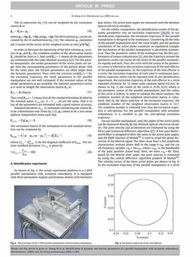
As shown in Fig. 2, the actual experiment platform is a 2-DOFparallel manipulator with actuation redundancy. It is equippedwith three permanent magnet synchronous motors with harmonic
Fig. 2. The prototype of the 2-DOF parallel manipulator with actuation redundancy.
Please cite this article in press as: Shang W et al. Identification of dynamic andMechatronics (2009), doi:10.1016/j.mechatronics.2009.11.005
gear drives. The active joint angles are measured with the absoluteoptical-electrical encoders.
For the robotic manipulator, the identification results of the dy-namic parameters rely on excitation trajectories [28,29]. In ouridentification experiment, the excitation trajectory of the parallelmanipulator is designed in the workspace. Considering all the linksof the parallel manipulator have the same length, and the positioncoordinates of the active joints constitute an equilateral triangle,the mechanism of the parallel manipulator is absolutely symmet-rical. Thus the geometric centre of the workspace has the best per-formance of torque transmission [2], also the trajectory around thegeometric centre can excite all the joints of the parallel manipula-tor equally and well. Thus, the circle with the centre at the geomet-ric centre is selected as the excitation trajectory of the end-effectorof the parallel manipulator. As the trajectory of the end-effector isa circle, the excitation trajectory of each joint is continuous para-metric trajectory which can be repeated well. In our identificationexperiment, the excitation trajectory of the end-effector is a circlerepeated clockwise for 15 times with constant speed 0.2 m/s. Asshown in Fig. 3, the centre of the circle is (0.29, 0.25) which isthe geometric centre of the parallel manipulator, and the radiusof the circle is 0.04 m. In order to validate the above analysis, thecondition number of the weighted observation matrix is calcu-lated. And by the above selection of the excitation trajectory, thecondition number of the weighted observation matrix is 12.7.The condition number is relatively low, thus the excitation trajec-tory is sub-optimal. For the parallel manipulator with actuationredundancy, it is satisfied to get the sub-optimal excitationtrajectory.
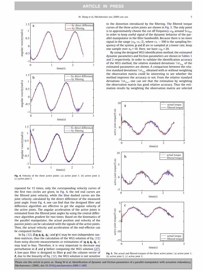
For our parallel manipulator, only the angles of the active jointscan be measured directly by the absolute optical–electrical encod-ers. The joint velocity and acceleration are estimated by using thefilters and numerical difference algorithm [27]. A low-pass Butter-worth filter is designed to filter the noise in the active joint angles,and the filtfilt function of MatlabTM is used to avoid the phase dis-tortion of the filtered signal. The filter must have a flat amplitudecharacteristic without phase shift in the range 0 xfq, and the cutoff frequency satisfies xfq > 10xdyn, where xdyn is the bandwidthof the joint position closed loop. Here, we have xfq = 40. Then,based on the filtered joint angle, the joint velocity is estimatedby using the central difference algorithm gradient of MatlabTM.The velocity curves of the three active joints are shown in Fig. 4.As the excitation trajectory of the parallel manipulator is a circle
Fig. 3. Excitation trajectory of the end-effector.
friction parameters of a parallel manipulator with actuation redundancy.
a
b
c
Fig. 4. Velocity of the three active joints: (a) active joint 1; (b) active joint 2;(c) active joint 3.
a
b
c
Fig. 5. The actual and filtered torques of the three active joints: (a) active joint 1;(b) active joint 2; (c) active joint 3.
W. Shang et al. / Mechatronics xxx (2009) xxx–xxx 5
ARTICLE IN PRESS
repeated for 15 times, only the corresponding velocity curves ofthe first two circles are given. In Fig. 4, the red real curves arethe filtered joint velocity, while the blue dashed curves are thejoint velocity calculated by the direct difference of the measuredjoint angle. From Fig. 4, one can find that the designed filter anddifference algorithm are effective to get the angular velocity ofthe active joints. The angular acceleration of the active joints isestimated from the filtered joint angles by using the central differ-ence algorithm gradient for two times. Based on the kinematics ofthe parallel manipulator, the actual position and velocity of thepassive joints can be calculated with the signals of the active joints.Then, the actual velocity and acceleration of the end-effector canbe computed further.
In Eq. (12), Zðq; _q; _qe; €qeÞ and y(s) may be non-independent ran-dom matrices, thus the calculation of the WLS solution of Eq. (12)from noisy discrete measurements or estimations of ðq; _q; _qe; €qe; sÞmay lead to bias. Therefore, it is very important to decrease anyperturbation in Z and y before computing the WLS solution [27].A low-pass filter is designed to filter y and the column vector ofZ, due to the linearity of Eq. (12), the WLS solution is not sensitive
Please cite this article in press as: Shang W et al. Identification of dynamic andMechatronics (2009), doi:10.1016/j.mechatronics.2009.11.005
to the distortion introduced by the filtering. The filtered torquecurves of the three active joints are shown in Fig. 5. The only pointis to approximately choose the cut off frequency xfp around 5xdyn
in order to keep useful signal of the dynamic behavior of the par-allel manipulator in the filter bandwidth. Because there is no moresignal in the range ½xfp xc=2�, where xc ¼ 500 is the sampling fre-quency of the system, y and Z are re-sampled at a lower rate, keepone sample over nd = 10. Here, we have xfp = 20.
By using the designed WLS identification method, the estimateddynamic parameters and friction parameters are shown in Tables 1and 2 respectively. In order to validate the identification accuracyof the WLS method, the relative standard deviations %ruwk
of theestimated parameters are shown. A comparison between the rela-tive standard deviations %ruwk
obtained with or without weightingthe observation matrix could be interesting to see whether themethod improves the accuracy or not. From the relative standarddeviations %ruwk
, one can see that the estimation by weightingthe observation matrix has good relative accuracy. Thus the esti-mation results by weighting the observation matrix are selected
friction parameters of a parallel manipulator with actuation redundancy.
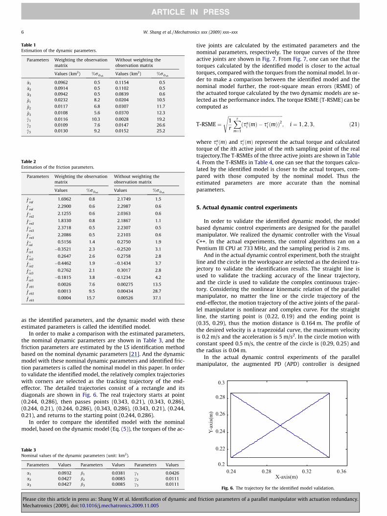
Table 1Estimation of the dynamic parameters.
Parameters Weighting the observationmatrix
Without weighting theobservation matrix
Values (km2) %ruwkValues (km2) %ruwk
a1 0.0962 0.5 0.1154 0.5a2 0.0914 0.5 0.1102 0.5a3 0.0942 0.5 0.0839 0.6
b1 0.0232 8.2 0.0204 10.5
b2 0.0117 6.8 0.0307 11.7
b3 0.0108 5.6 0.0370 12.3
c1 0.0116 10.3 0.0028 19.2c2 0.0109 7.6 0.0147 26.6c3 0.0130 9.2 0.0152 25.2
Table 2Estimation of the friction parameters.
Parameters Weighting the observationmatrix
Without weighting theobservation matrix
Values %ruwkValues %ruwk
fþval1.6962 0.8 2.1749 1.5
f�val2.2900 0.6 2.2987 0.6
fþva22.1255 0.6 2.0363 0.6
f�va21.8330 0.8 2.1867 1.1
fþva32.3718 0.5 2.2307 0.5
f�va32.2086 0.5 2.2103 0.6
fþcal0.5156 1.4 0.2750 1.9
f�ca1�0.3521 2.3 �0.2520 3.1
fþca20.2647 2.6 0.2758 2.8
f�ca2�0.4462 1.9 �0.1434 3.7
fþca30.2762 2.1 0.3017 2.8
f�ca3�0.1815 3.8 �0.1234 4.2
f vb10.0026 7.6 0.00275 13.5
f vb20.0013 9.5 0.00434 28.7
f vb30.0004 15.7 0.00526 37.1
6 W. Shang et al. / Mechatronics xxx (2009) xxx–xxx
ARTICLE IN PRESS
as the identified parameters, and the dynamic model with theseestimated parameters is called the identified model.
In order to make a comparison with the estimated parameters,the nominal dynamic parameters are shown in Table 3, and thefriction parameters are estimated by the LS identification methodbased on the nominal dynamic parameters [21]. And the dynamicmodel with these nominal dynamic parameters and identified fric-tion parameters is called the nominal model in this paper. In orderto validate the identified model, the relatively complex trajectorieswith corners are selected as the tracking trajectory of the end-effector. The detailed trajectories consist of a rectangle and itsdiagonals are shown in Fig. 6. The real trajectory starts at point(0.244, 0.286), then passes points (0.343, 0.21), (0.343, 0.286),(0.244, 0.21), (0.244, 0.286), (0.343, 0.286), (0.343, 0.21), (0.244,0.21), and returns to the starting point (0.244, 0.286).
In order to compare the identified model with the nominalmodel, based on the dynamic model (Eq. (5)), the torques of the ac-
Table 3Nominal values of the dynamic parameters (unit: km2).
Parameters Values Parameters Values Parameters Values
a1 0.0932 b1 0.0381 c1 0.0426a2 0.0427 b2 0.0085 c2 0.0111a3 0.0427 b3 0.0085 c3 0.0111
Please cite this article in press as: Shang W et al. Identification of dynamic andMechatronics (2009), doi:10.1016/j.mechatronics.2009.11.005
tive joints are calculated by the estimated parameters and thenominal parameters, respectively. The torque curves of the threeactive joints are shown in Fig. 7. From Fig. 7, one can see that thetorques calculated by the identified model is closer to the actualtorques, compared with the torques from the nominal model. In or-der to make a comparison between the identified model and thenominal model further, the root-square mean errors (RSME) ofthe actuated torque calculated by the two dynamic models are se-lected as the performance index. The torque RSME (T-RSME) can becomputed as
T-RSME ¼ffiffiffiffiffiffiffiffiffiffiffiffiffiffiffiffiffiffiffiffiffiffiffiffiffiffiffiffiffiffiffiffiffiffiffiffiffiffiffiffiffiffiffiffiffiffiffiffi1r
Xr
m¼1
ðsai ðmÞ � sc
i ðmÞÞ2
s; i ¼ 1;2;3; ð21Þ
where sai ðmÞ and sc
i ðmÞ represent the actual torque and calculatedtorque of the ith active joint of the mth sampling point of the realtrajectory.The T-RSMEs of the three active joints are shown in Table4. From the T-RSMEs in Table 4, one can see that the torques calcu-lated by the identified model is closer to the actual torques, com-pared with those computed by the nominal model. Thus theestimated parameters are more accurate than the nominalparameters.
5. Actual dynamic control experiments
In order to validate the identified dynamic model, the modelbased dynamic control experiments are designed for the parallelmanipulator. We realized the dynamic controller with the VisualC++. In the actual experiments, the control algorithms ran on aPentium III CPU at 733 MHz, and the sampling period is 2 ms.
And in the actual dynamic control experiment, both the straightline and the circle in the workspace are selected as the desired tra-jectory to validate the identification results. The straight line isused to validate the tracking accuracy of the linear trajectory,and the circle is used to validate the complex continuous trajec-tory. Considering the nonlinear kinematic relation of the parallelmanipulator, no matter the line or the circle trajectory of theend-effector, the motion trajectory of the active joints of the paral-lel manipulator is nonlinear and complex curve. For the straightline, the starting point is (0.22, 0.19) and the ending point is(0.35, 0.29), thus the motion distance is 0.164 m. The profile ofthe desired velocity is a trapezoidal curve, the maximum velocityis 0.2 m/s and the acceleration is 5 m/s2. In the circle motion withconstant speed 0.5 m/s, the centre of the circle is (0.29, 0.25) andthe radius is 0.04 m.
In the actual dynamic control experiments of the parallelmanipulator, the augmented PD (APD) controller is designed
Fig. 6. The trajectory for the identified model validation.
friction parameters of a parallel manipulator with actuation redundancy.
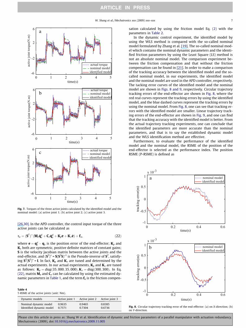
a
b
c
Fig. 7. Torques of the three active joints calculated by the identified model and thenominal model: (a) active joint 1; (b) active joint 2; (c) active joint 3.
a
b
W. Shang et al. / Mechatronics xxx (2009) xxx–xxx 7
ARTICLE IN PRESS
[26,30]. In the APD controller, the control input torque of the threeactive joints can be calculated as
sa ¼ ðSTÞþðMe €qde þ Ce _qd
e þ Kpeþ Kv _eÞ þ fa; ð22Þ
where e ¼ qde � qe is the position error of the end-effector; Kp and
Kv both are symmetric, positive definite matrices of constant gains;S is the velocity Jacobian matrix between the active joints and theend-effector, and (ST)+ = S(STS)-1 is the Pseudo-inverse of ST, satisfy-ing ST(ST)+ = I. In fact, Kp and Kv are tuned and determined by theactual experiments. In our actual experiments, Kp and Kv are tunedas follows: Kp ¼ diagð35;000;35;000Þ;Kv ¼ diagð300;300Þ. In Eq.(22), matrix Me and Ce can be calculated by using the estimated dy-namic parameters in Table 1, and the term fa is the friction compen-
Table 4T-RSME of the active joints (unit: Nm).
Dynamic models Active joint 1 Active joint 2 Active joint 3
Nominal dynamic model 0.9635 0.9465 0.8385Identified dynamic model 0.7571 0.7304 0.6736
Please cite this article in press as: Shang W et al. Identification of dynamic andMechatronics (2009), doi:10.1016/j.mechatronics.2009.11.005
sation calculated by using the friction model Eq. (2) with theparameters in Table 2.
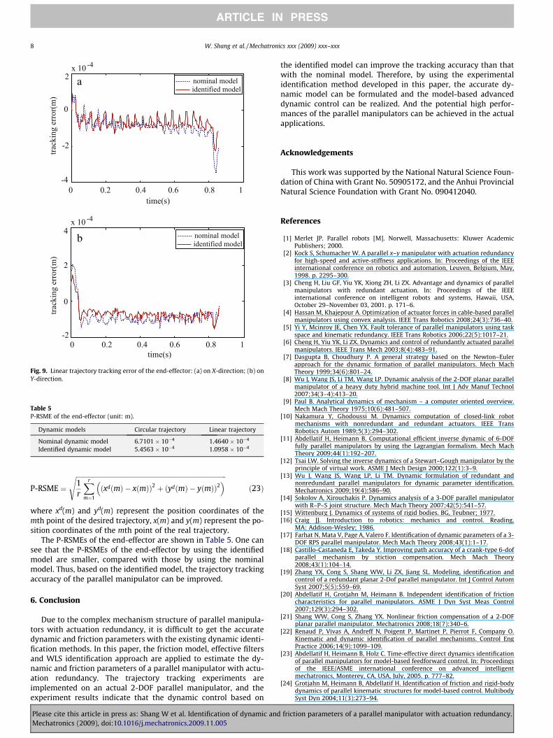
In the dynamic control experiment, the identified model byusing the WLS method is compared with the so-called nominalmodel formulated by Zhang et al. [19]. The so-called nominal mod-el which contains the nominal dynamic parameters and the identi-fied friction parameters by using the Least Square (LS) method isnot an absolute nominal model. The comparison experiment be-tween the friction compensation and that without the frictioncompensation can be found in [21]. In order to make a comparisonof the tracking accuracy between the identified model and the so-called nominal model, in our experiments, the identified modeland the nominal model are used in the APD controller, respectively.The tacking error curves of the identified model and the nominalmodel are shown in Figs. 8 and 9, respectively. Circular trajectorytracking errors of the end-effector are shown in Fig. 8, where thered real curves represent the tracking errors by using the identifiedmodel, and the blue dashed curves represent the tracking errors byusing the nominal model. From Fig. 8, one can see that tracking er-rors with the identified model are smaller. Linear trajectory track-ing errors of the end-effector are shown in Fig. 9, and one can findthat the tracking accuracy with the identified model is better. Fromthe actual trajectory tracking experiments, one can conclude thatthe identified parameters are more accurate than the nominalparameters, and that is to say the established dynamic modeland the WLS identification method are effective.
Furthermore, to evaluate the performance of the identifiedmodel and the nominal model, the RSME of the position of theend-effector is selected as the performance index. The positionRSME (P-RSME) is defined as
Fig. 8. Circular trajectory tracking error of the end-effector: (a) on X-direction; (b)on Y-direction.
friction parameters of a parallel manipulator with actuation redundancy.
a
b
Fig. 9. Linear trajectory tracking error of the end-effector: (a) on X-direction; (b) onY-direction.
Table 5P-RSME of the end-effector (unit: m).
Dynamic models Circular trajectory Linear trajectory
Nominal dynamic model 6.7101 � 10�4 1.4640 � 10�4
Identified dynamic model 5.4563 � 10�4 1.0958 � 10�4
8 W. Shang et al. / Mechatronics xxx (2009) xxx–xxx
ARTICLE IN PRESS
P-RSME ¼ffiffiffiffiffiffiffiffiffiffiffiffiffiffiffiffiffiffiffiffiffiffiffiffiffiffiffiffiffiffiffiffiffiffiffiffiffiffiffiffiffiffiffiffiffiffiffiffiffiffiffiffiffiffiffiffiffiffiffiffiffiffiffiffiffiffiffiffiffiffiffiffiffiffiffiffiffiffiffiffiffiffiffiffiffiffiffiffiffiffiffiffiffi1r
Xr
m¼1
ðxdðmÞ � xðmÞÞ2 þ ðydðmÞ � yðmÞÞ2� �s
ð23Þ
where xd(m) and yd(m) represent the position coordinates of themth point of the desired trajectory, x(m) and y(m) represent the po-sition coordinates of the mth point of the real trajectory.
The P-RSMEs of the end-effector are shown in Table 5. One cansee that the P-RSMEs of the end-effector by using the identifiedmodel are smaller, compared with those by using the nominalmodel. Thus, based on the identified model, the trajectory trackingaccuracy of the parallel manipulator can be improved.
6. Conclusion
Due to the complex mechanism structure of parallel manipula-tors with actuation redundancy, it is difficult to get the accuratedynamic and friction parameters with the existing dynamic identi-fication methods. In this paper, the friction model, effective filtersand WLS identification approach are applied to estimate the dy-namic and friction parameters of a parallel manipulator with actu-ation redundancy. The trajectory tracking experiments areimplemented on an actual 2-DOF parallel manipulator, and theexperiment results indicate that the dynamic control based on
Please cite this article in press as: Shang W et al. Identification of dynamic andMechatronics (2009), doi:10.1016/j.mechatronics.2009.11.005
the identified model can improve the tracking accuracy than thatwith the nominal model. Therefore, by using the experimentalidentification method developed in this paper, the accurate dy-namic model can be formulated and the model-based advanceddynamic control can be realized. And the potential high perfor-mances of the parallel manipulators can be achieved in the actualapplications.
Acknowledgements
This work was supported by the National Natural Science Foun-dation of China with Grant No. 50905172, and the Anhui ProvincialNatural Science Foundation with Grant No. 090412040.
References
[1] Merlet JP. Parallel robots [M]. Norwell, Massachusetts: Kluwer AcademicPublishers; 2000.
[2] Kock S, Schumacher W. A parallel x–y manipulator with actuation redundancyfor high-speed and active-stiffness applications. In: Proceedings of the IEEEinternational conference on robotics and automation, Leuven, Belgium, May,1998. p. 2295–300.
[3] Cheng H, Liu GF, Yiu YK, Xiong ZH, Li ZX. Advantage and dynamics of parallelmanipulators with redundant actuation. In: Proceedings of the IEEEinternational conference on intelligent robots and systems, Hawaii, USA,October 29–November 03, 2001. p. 171–6.
[4] Hassan M, Khajepour A. Optimization of actuator forces in cable-based parallelmanipulators using convex analysis. IEEE Trans Robotics 2008;24(3):736–40.
[5] Yi Y, Mcinroy JE, Chen YX. Fault tolerance of parallel manipulators using taskspace and kinematic redundancy. IEEE Trans Robotics 2006;22(5):1017–21.
[6] Cheng H, Yiu YK, Li ZX. Dynamics and control of redundantly actuated parallelmanipulators. IEEE Trans Mech 2003;8(4):483–91.
[7] Dasgupta B, Choudhury P. A general strategy based on the Newton–Eulerapproach for the dynamic formation of parallel manipulators. Mech MachTheory 1999;34(6):801–24.
[8] Wu J, Wang JS, Li TM, Wang LP. Dynamic analysis of the 2-DOF planar parallelmanipulator of a heavy duty hybrid machine tool. Int J Adv Manuf Technol2007;34(3–4):413–20.
[9] Paul B. Analytical dynamics of mechanism – a computer oriented overview.Mech Mach Theory 1975;10(6):481–507.
[10] Nakamura Y, Ghodoussi M. Dynamics computation of closed-link robotmechanisms with nonredundant and redundant actuators. IEEE TransRobotics Autom 1989;5(3):294–302.
[11] Abdellatif H, Heimann B. Computational efficient inverse dynamic of 6-DOFfully parallel manipulators by using the Lagrangian formalism. Mech MachTheory 2009;44(1):192–207.
[12] Tsai LW. Solving the inverse dynamics of a Stewart–Gough manipulator by theprinciple of virtual work. ASME J Mech Design 2000;122(1):3–9.
[13] Wu J, Wang JS, Wang LP, Li TM. Dynamic formulation of redundant andnonredundant parallel manipulators for dynamic parameter identification.Mechatronics 2009;19(4):586–90.
[14] Sokolov A, Xirouchakis P. Dynamics analysis of a 3-DOF parallel manipulatorwith R–P–S joint structure. Mech Mach Theory 2007;42(5):541–57.
[15] Wittenburg J. Dynamics of systems of rigid bodies. BG, Teubner; 1977.[16] Craig JJ. Introduction to robotics: mechanics and control. Reading,
MA: Addison-Wesley; 1986.[17] Farhat N, Mata V, Page A, Valero F. Identification of dynamic parameters of a 3-
DOF RPS parallel manipulator. Mech Mach Theory 2008;43(1):1–17.[18] Castillo-Castaneda E, Takeda Y. Improving path accuracy of a crank-type 6-dof
parallel mechanism by stiction compensation. Mech Mach Theory2008;43(1):104–14.
[19] Zhang YX, Cong S, Shang WW, Li ZX, Jiang SL. Modeling, identification andcontrol of a redundant planar 2-Dof parallel manipulator. Int J Control AutomSyst 2007;5(5):559–69.
[20] Abdellatif H, Grotjahn M, Heimann B. Independent identification of frictioncharacteristics for parallel manipulators. ASME J Dyn Syst Meas Control2007;129(3):294–302.
[21] Shang WW, Cong S, Zhang YX. Nonlinear friction compensation of a 2-DOFplanar parallel manipulator. Mechatronics 2008;18(7):340–6.
[22] Renaud P, Vivas A, Andreff N, Poigent P, Martinet P, Pierrot F, Company O.Kinematic and dynamic identification of parallel mechanisms. Control EngPractice 2006;14(9):1099–109.
[23] Abdellatif H, Heimann B, Holz C. Time-effective direct dynamics identificationof parallel manipulators for model-based feedforward control. In: Proceedingsof the IEEE/ASME international conference on advanced intelligentmechatronics, Monterey, CA, USA, July, 2005. p. 777–82.
[24] Grotjahn M, Heimann B, Abdellatif H. Identification of friction and rigid-bodydynamics of parallel kinematic structures for model-based control. MultibodySyst Dyn 2004;11(3):273–94.
friction parameters of a parallel manipulator with actuation redundancy.
W. Shang et al. / Mechatronics xxx (2009) xxx–xxx 9
ARTICLE IN PRESS
[25] Wu J, Wang JS, Wang LP. Identification of dynamic parameter of 3DOF parallelmanipulator with actuation redundancy. J Manuf Sci Eng2008;130(4):1005–11.
[26] Murray R, Li ZX, Sastry S. A mathematical introduction to roboticmanipulation. CRC Press; 1994.
[27] Gautier M, Poignet Ph. Extended Kalman filtering and weighted leastsquares dynamic identification of robot. Control Eng Practice2001;9(12):1361–72.
Please cite this article in press as: Shang W et al. Identification of dynamic andMechatronics (2009), doi:10.1016/j.mechatronics.2009.11.005
[28] Swevers J, Ganseman C, DeSchutter J, VanBrussel H. Generation of periodictrajectories for optimal robot excitation. ASME Trans J Manuf Sci Eng1997;119(4):611–5.
[29] Kostic D, DeJager B, Steinbuch M, Hensen R. Modeling and identification forhigh-performance robot control: an RRR-robotic arm case study. IEEE TransControl Syst Technol 2004;12(6):904–17.
[30] Koditschek D. Natural motion for robot arms. In: Proceedings of the IEEEcontrol and decision conference; 1984. p. 733–5.
friction parameters of a parallel manipulator with actuation redundancy.
Related Documents