119 Cabur control terminal boards have been developed in order to enable electric power suppliers and users to easily check measuring instruments, without interrupting the current carrying circuits during the verification itself or during the replacement of the instruments. Each terminal board is composed by an insulating body, carrying the copper zinc alloy terminals to which the ammeter, voltmeter circuits and the devices for disconnect and short circuit operations are connected. Each terminal board is supplied with a transparent cover (of cellulose acetate), provided with appropriate captive screws for the sealing of the assembly. In two-phase and three-phase terminal boards, the insulating base is built from Kelon (an abbreviation of Keramic + Nylon): this is a nylon 6 based, self-extinguishing UL94V-0 polymer with the addition of special ceramic spheres and subsequent thermal stability. The inclusion of the microspheres and the thermal procedure make the item extremely hardwearing (rigid, but also able to withstand impacts and wear and tear) The current phases are marked in different colours, to be defined when ordering. TECHNICAL CHARACTERISTICS rated cross-section 6 mm 2 connecting capacity flexible conductors 0,5 ÷ 6 mm 2 rigid conductors 0,5 ÷ 6 mm 2 conductors insertion hole Ø 4,1 (mm) tightening torque 1,2 (Nm) rated current (conf. to IEC 60947-7-1) 57 A rated voltage (conf. to IEC 60947-7-1) 500 V rated impulse withstand voltage / pollution degree 6 KV / 3

Welcome message from author
This document is posted to help you gain knowledge. Please leave a comment to let me know what you think about it! Share it to your friends and learn new things together.
Transcript

119
Cabur control terminal boards have been developed in order to enable electric power suppliers and users to easily check measuring instruments, without interrupting the current carrying circuits during the verification itself or during the replacement of the instruments.
Each terminal board is composed by an insulating body, carrying the copper zinc alloy terminals to which the ammeter, voltmeter circuits and the devices for disconnect and short circuit operations are connected. Each terminal board is supplied with a transparent cover (of cellulose acetate), provided with appropriate captive screws for the sealing of the assembly.
In two-phase and three-phase terminal boards, the insulating base is built from Kelon (an abbreviation of Keramic + Nylon): this is a nylon 6 based, self-extinguishing UL94V-0 polymer with the addition of special ceramic spheres and subsequent thermal stability. The inclusion of the microspheres and the thermal procedure make the item extremely hardwearing (rigid, but also able to withstand impacts and wear and tear)
The current phases are marked in different colours, to be defined when ordering.
TECHNICAL CHARACTERISTICSrated cross-section 6 mm2
connecting capacity flexible conductors 0,5 ÷ 6 mm2
rigid conductors 0,5 ÷ 6 mm2
conductors insertion hole Ø 4,1 (mm)tightening torque 1,2 (Nm)rated current (conf. to IEC 60947-7-1) 57 Arated voltage (conf. to IEC 60947-7-1) 500 Vrated impulse withstand voltage / pollution degree 6 KV / 3

120
The use of MCM series control terminal boards allows:
1) disconnection, upstream and downstream the measuring
instruments
2) the insertion of a test instrument, downstream or upstream the
measuring instruments
3) shunting, by means of common plugs, from the four connection
terminals
4) voltage transmission from the beginning of the ammeter circuit to
the disconnect slide-link by means of a simple cross connections.
In normal service, voltmeter leads are connected to the R-S-T
terminals, whilst the ammeter leads, are to be inserted in the terminals
identified R1-R2, S1-S2, T1-T2. The instruments are connected
to terminals 1 and 2. The vertical slide-link cross connections are
closed, the horizontal slide-link cross connections are open.
When inserting control instruments, the following instructions are to
be followed:
- by means of normal plugs, the voltmeter leads must be shunted
from the test instrument on to the voltage sockets of the disconnect
slide-link or to the insertion blocks of the fuse-holders;
- the ammeter leads of the test instruments must be inserted in
sockets 1 ad R1 or 2 ad R2; same procedure is to be followed for
the other phases;
- therefore, the corresponding vertical slide-link must be disconnected.
If there is a need to replace a measuring instrument, it is necessary
to previously close the horizontal slide-links, disconnect the vertical
slide-links and open the slide-link.
Feeding conductors (incoming and outcoming) are inserted from the
rear of the terminal board, with conductors passing through slots on
the insulating base of the terminal board.
Overall dimension (with cover)MCM.1: 95 x 85 x 48 mm
ENEL in order to identify phases, has adopted a particular colour convention, based on the sections where terminal blocks are installed.From the left, phases are identified as follows:
MCM.1/B (white) MC201B (adopted in Campania and Lombardy)MCM.1/G (yellow) MC201G (adopted in Veneto and Trentino Alto Adige)MCM.1/R (red) MC201R (adopted in the rest of Italy)
Application scheme
for single-phase connectedelectric power meters
MCM.1
Fixing template
Type Cat. No.
MCM Series

121
Overall dimension (with cover)MCM.1: 95 x 85 x 48 mm
Application scheme
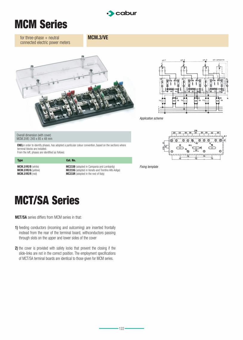
for three-phase + neutralconnected electric power meters
MCM.3
Fixing template
Overall dimension (with cover)MCM.2: 170 x 85 x 48 mm
Application scheme
for ARON connectedelectric power meters
MCM.2
Fixing template
ENELin order to identify phases, has adopted a particular colour convention, based on the sections where terminal blocks are installed.From the left, phases are identified as follows::
MCM.2/B (white) MC202B (adopted in Campania and Lombardy)MCM.2/G (yellow) MC202G (adopted in Veneto and Trentino Alto Adige)MCM.2/R (red) MC202R (adopted in the rest of Italy)
ENELin order to identify phases, has adopted a particular colour convention, based on the sections where terminal blocks are installed.From the left, phases are identified as follows:
MCM.3/B (white) MC203B (adopted in Campania and Lombardy)MCM.3/G (yellow) MC203G (adopted in Veneto and Trentino Alto Adige)MCM.3/R (red) MC203R (adopted in the rest of Italy)
MCM Series
Type Cat. No.
Type Cat. No.
122
Application scheme
for three-phase + neutralconnected electric power meters
MCM.3/VE
Fixing template
MCM Series
Overall dimension (with cover)MCM.3/VE: 245 x 85 x 48 mm
ENELin order to identify phases, has adopted a particular colour convention, based on the sections where terminal blocks are installed.From the left, phases are identified as follows:
MCM.3/VE/B (white) MC233B (adopted in Campania and Lombardy)MCM.3/VE/G (yellow) MC233G (adopted in Veneto and Trentino Alto Adige)MCM.3/VE/R (red) MC233R (adopted in the rest of Italy)
Type Cat. No.
MCT/SA series differs from MCM series in that:
1) feeding conductors (incoming and outcoming) are inserted frontally
instead from the rear of the terminal board, withconductors passing
through slots on the upper and lower sides of the cover
2) the cover is provided with safety locks that prevent the closing if the
slide-links are not in the correct position. The employment specifications
of MCT/SA terminal boards are identical to those given for MCM series.
MCT/SA Series

123
MCT/SA Series
Overall dimension (with cover)MCT.1/SA: 95 x 85 x 48 mm
Application scheme
for single-phase connectedelectric power meters
MCT.1/SA
Fixing template
ENELin order to identify phases, has adopted a particular colour convention, based on the sections where terminal blocks are installed.From the left, phases are identified as follows:
MCT.1/SA/B (white) MC401B (adopted in Campania and Lombardy)MCT.1/SA/G (yellow) MC401G (adopted in Veneto and Trentino Alto Adige)MCT.1/SA/R (red) MC401R (adopted in the rest of Italy)
Type Cat. No.
Application scheme
for ARON connectedelectric power meters
MCT.2/SA
Overall dimension (with cover)MCT.2/SA: 170 x 85 x 48 mm
ENELin order to identify phases, has adopted a particular colour convention, based on the sections where terminal blocks are installed.From the left, phases are identified as follows:
MCT.2/SA/B (white) MC402B (adopted in Campania and Lombardy)MCT.2/SA/G (yellow) MC402G (adopted in Veneto and Trentino Alto Adige)MCT.2/SA/R (red) MC402R (adopted in the rest of Italy)
Type Cat. No.
Fixing template

124
- support pitch: 20 mm
- both types are suited for 6 x 6 mm or 10 x 3 mm busbars
- insulating body: of beige polyamide (RAL 1001); KC 600 degree tracking resistance,
UL94V-0 self-extinguishing degree. Temperature range: between - 30°C and +110°C.
Provided with two housing for the marking compositions of letters or numbers (up to
3 figures), by means of CSC tags, and card holders with transparent protection for
identification inscription.
SDN/D
SDN/H
(Cat. No. SD200)to be mounted on rails according to IEC 60715 Std.
(Cat. No. SD300)to be screwed directly on panel
SDN/HSDN/D
MCT/SA Series
Application scheme
for three-phase + neutralconnected electric power meters
MCT.3/SA
Fixing template
Overall dimension (with cover)MCT.3/SA: 245 x 85 x 48 mm
ENEL in order to identify phases, has adopted a particular colour convention, based on the sections where terminal blocks are installed.From the left, phases are identified as follows:
MCT.3/SA/B (white) MC403B (adopted in Campania and Lombardy)MCT.3/SA/G (yellow) MC403G (adopted in Veneto and Trentino Alto Adige)MCT.3/SA/R (red) MC403R (adopted in the rest of Italy)
Type Cat. No.
SDN neutralbusbar supports

125
MS.8x10 disconnect terminal board8-poles, 4 ammetric and 4 voltmetric
MS/8x10/N Cat. No. MZ300N
TECHNICAL CHARACTERISTICSrated cross-section 10 mm2
connecting capacity flexible conductors 0,5 ÷ 16 mm2
conductors insertion hole 5 x 10 (mm)test tightening torque 120 (Ncm)rated current (conf. to IEC 60947-7-1) 57 Arated voltage (conf. to IEC 60947-7-1) 500 Vrated impulse withstand voltage / pollution degree 6 KV / 3thickness (with cover, including screws) 52 / 65 mm
Insulating body: of green polycarbonate, filled with fibreglass.Conductor body: components of copper-zinc alloy with high percentage of copper and provided with nickel plating.Cover: of black polyamide.
A version with cover in transparent cellulose acetate is available.
MS/8x10/T MZ300T
On request, the terminal board can be supplied according to different electrical schemes.
Cat. No. MZ300N(black cover)
Cat. No. MZ300T(transparent cover)
Type Cat. No.

126
Blue version QBLOK.7/BLU Cat. No. QBLOK7001
QBLOK.12/BLU Cat. No. QBLOK1201
Green version QBLOK.7/TE Cat. No. QBLOK7002
QBLOK.12/TE Cat. No. QBLOK1202
height / width / thickness TH/35 7,5 mm 33 / 53 / 16 33 / 85 / 16height / width / thickness TH/35 15 mm 41 / 53 / 16 41 / 85 / 16
TECHNICAL CHARACTERISTICSfunction / type Distribution terminal boards Distribution terminal boardsnumber and diameter of holes 7 holes ø 5,3 mm 12 holes ø 5,3 mmsezione nominale (mm2) 10 10connecting capacity: flexible (mm2) rigid (mm2) max. flexible with ferrule (mm2)-ferrule type
1,5 ÷ 101,5 10 - WP100/21
1,5 ÷ 101,5 10 - WP100/21
rated voltage / rated current / gauge conf. to IEC 60947-1 500 V / 63 A / B5 500 V / 63 A / B5rated impulse withstand voltage / pollution degree - -insulation stripping length (mm) 6 6tightening torque value (test / max) (Nm) 2 / 2,5 Nm 2 / 2,5 Nm
APPROVALS IMQ pending IMQ pending
ACCESSORIES Type Cat. No. Type Cat. No.
Marking tag printed or blank CNU/8/51 NU0851 CNU/8/51 NU0851End bracket BTU for PR/DIN and PR/3 BT005
BT/3-BTO for PR/3 only BT003-BT007BTU for PR/DIN and PR/3 BT005BT/3-BTO for PR/3 only BT003-BT007
Mounting rail according to IEC 60715 Std. PR/3/AC of steel PR003
PR/3/AS same with slots PR005PR/3/AC of steel PR003PR/3/AS idem con asole PR005
Applications
Distribution terminal boards are used as supplementary
terminal boards for phase or neutral expansion inside
electrical panels. They are also called equipotential
terminal boards since they are used as equipotential
nodes in distribution control units to house the
earthing system.
General characteristics
• Configuration, with 7 and 12 holes
• Mounting onto PR/3, type “TH/35 “ rails according
to IEC 60715 Std.
• Intrinsically IPXXB protected according to IEC
60529 Std.
• Marking possibility with CNU/8 or CNU/10 tags on
each busbar
• Available in green and blue
• Insulating in polyamide 6.6 UL94V-0
QBLOK series

127
Applications
Distribution terminal boards are used as supplementary
terminal boards for phase or neutral expansion inside
electrical panels. They are also called equipotential
terminal boards since they are used as equipotential
nodes in distribution control units to house the
earthing system.
General characteristics
• Protected terminal boards with 7,11, and 15 holes
• Fixing: DIN rail or panel-mount with screws
• Rated voltage 500V according to IEC 60947-7-1 Std.
• Conforming to EU Low voltage Directive
2006/95/EC
Materials
• CW 614N Brass
• Zinc-plated steel screws with combinated
single-slot and Phillips heads
POLM series
CAT. NO. TYPE COLOUR RATED CROSS-
SECTION (mm2)RATED CURRENT
NUMBER OF
HOLES
QPOL1203 POLM.1215 Grey
12 x 1,5
2 x 2,5
1 x 16
80 A
The 16mm²
diameter hole is
screw-clamped type
QPOL1204 POLM.1215/TE Blue
12 x 1,5
2 x 2,5
1 x 16
80 A
The 16mm²
diameter hole is
screw-clamped type
QPOL1205 POLM.1215/BLU Green
12 x 1,5
2 x 2,5
1 x 16
80 A
The 16mm²
diameter hole is
screw-clamped type
QPOL7005 POLM.7/TRA Transparent 1,5-10,0 57 A 7
QPOL1105 POLM.11/TRA Transparent 1,5-10,0 57 A 11
QPOL1505 POLM.15/TRA Transparent 1,5-10,0 57 A 15
Spring clamp
Spring clamp
Spring clamp

128
VERSION QBLOK4P100A7 Cat. No. QBLOK4100
QBLOK4P125A11 Cat. No. QBLOK4125
QBLOK4P125A15 Cat. No. QBLOK4126
height / width / thickness TH/35 7,5 mm 52 / 97 / 71 52 / 97 / 108 52 / 97 / 137height / width / thickness TH/35 15 mm 59 / 97 / 71 59 / 97 / 108 59 / 97 / 137
TECHNICAL CHARACTERISTICS
function / type Distribution 4-pole terminal board Distribution 4-pole terminal board Distribution 4-pole terminal boardnumber and diameter of holes 2 holes ø 7.5 mm + 5 holes ø 5.4 mm 2 holes ø 9 mm + 2 holes ø 7,5 mm
+7 holes ø 5.4 mm2 holes ø 9 mm + 2 holes ø 7,5 mm + 11 holes ø 5,4 mm
rated cross-section (mm2) 25 35 35connecting capacity (hole ø 9 mm): flexible (mm2) rigid (mm2) max. flexible with ferrule (mm2)-ferrule type
10 ÷ 3510 ÷ 3525 - WP 250/29
10 ÷ 3510 ÷ 3525 - WP 250/29
connecting capacity (hole ø 9 mm): flexible (mm2) rigid (mm2) max. flexible with ferrule (mm2)-ferrule type
10 ÷ 2510 ÷ 2516 - WP160/22
10 ÷ 2510 ÷ 2516 - WP 160/22
10 ÷ 2510 ÷ 2516 - WP 160/22
connecting capacity (hole ø 5,4 mm): flexible (mm2) rigid (mm2) max. flexible with ferrule (mm2)-ferrule type
2.5 ÷ 62,5 ÷ 64 - WP40/16
2,5 ÷ 62,5 ÷ 64 - WP 40/16
2,5 ÷ 62,5 ÷ 64 - WP 40/16
rated voltage / rated current / gauge conf. to IEC 60947-7-1 500 V / 100 A / - 500 V / 125 A / - 500 V / 125 A / -Short-time withstand current (Icw) conf. to IEC 60947-7-1 3 kA (r.m.s value x 1s) 3 kA (r.m.s value x 1s) 3 kA (r.m.s value x 1s)
rated impulse withstand voltage / pollution degree 8 kV / 3 - -insulation stripping length (mm) 13 13 13tightening torque value (test / max) (Nm) 1,8 / 2,2 Nm 1,8 / 2,2 Nm 1,8 / 2,2 Nm
APPROVALS
ACCESSORIES Type Cat. No. Type Cat. No. Type Cat. No.
Marking tag printed or blank CNU/8/51/... NU0851...CNU/10/51/... NU1051…
CNU/8/51/... NU0851...CNU/10/51/... NU1051…
CNU/8/51/... NU0851...CNU/10/51/... NU1051…
End bracket BTU for PR/DIN and PR/3 BT005BT/3-BTO for PR/3 only BT003-BT007-
BTU for PR/DIN and PR/3 BT005BT/3-BTO for PR/3 only BT003-BT007-
BTU for PR/DIN and PR/3 BT005BT/3-BTO for PR/3 only BT003-BT007-
Mounting rail according to IEC 60715 Std. PR/3/AC in acciaio PR003
PR/3/AS idem con asole PR005PR/3/AC in acciaio PR003PR/3/AS idem con asole PR005
PR/3/AC in acciaio PR003PR/3/AS idem con asole PR005
Applications
Distribution terminal boards
General characteristics
• Four pole configuration, with 2 ø 7,5 mm holes
and 5 ø 5,4 mm holes
• Mounting onto PR/3, type “TH/35 “ rails according
to IEC 60715 Std. or directly onto the panel
• Insulating supports in polyamide 6.6 and
insulating cover in polycarbonate - UL94V-0 grade
• Insulating cover on each conducting body
• Feeding inputs in staggered position for easier
conductor connection
• Marking possibility with CNU/8 or CNU/10 tags on
each busbar
• IMQ approval in conformity to EN 60947-7-1 Std.
QBLOK series

129
General characteristics
• Fixing: EN 50022 rail or panel-mount
• Insulating screen on each brass busbar
• Holes specially staggered for better cabling
of the conductors
• IMQ certificate (extension) and conformity
to EU 2006/95/EC Low Voltage Directive
Materials
• CW 614N Brass
• Zinc-plated steel screws with combined
single-slot and Phillips heads
• Transparent polycarbonate
POLM/N seriesDistribution terminal boards
CAT. NO. TYPEDIAMETER OF
BAR HOLES (mm)
BAR
NUMBER I MAX V MAX PACKAGE A (mm) B (mm) C (mm)
QPOL2100N POLM.2/100/N5,0 x 5,5
2,0 x 7,52 100 A 500V 4 47,0 69,0 50,0
QPOL2125N POLM.2/125/N
7,0 x 5,4
2,0 x 7,5
2,0 x 9,0
2 125 A 500V 2 47,0 106,0 50,0
QPOL2126N POLM.2/126/N
11,0 x 5,4
2,0 x 7,5
2,0 x 9,0
2 125 A 500V 2 47,0 106,0 50,0
QPOL4160S POLM.4/160/S
6,0 x 6,5
2,0 x 8,5
1,0 x 11,0
4 160 A 500V 1 87,0 135,0 52,0
QPOL4161N POLM.4/161/N
9,0 x 6,5
4,0 x 8,5
1,0 x 11,0
4 160 A 500V 1 88,0 182,0 55,0
A
B
C

133
234 mm
340 mm
30 mm
27
mm
38
mm
39 mm
CAT. NO. TYPE CORRENT DIMENSIONSSHORT CIRCUIT
CURRENT
5000V 10000V
CSBR5400 SUPP/5400
160A 5,0 x 15,0 500,0 mm 450,0 mm
250A 5,0 x 20,0 750,0 mm 450,0 mm
320A 5,0 x 25,0 750,0 mm 450,0 mm
400A 5,0 x 32,0 750,0 mm 450,0 mm
The SUPP/5400 support allows rapid and secure fixing of copper
busbars for power distribution. The different dimensions of the
busbars perfectly adapt to the SUPP/5400 support, by simply rotating
the closing cover which has different sized grooves for the immediate
fixing of any of the four different busbars indicated in the table. The
last columns of the table indicate the support c-to-c (distance between
centers) distances necessary in function of the maximum rated current
and the maximum allowable short circuit current.
General characteristics
• Loads from 160A to 400A
• Equipped for insertion of the earthing bar, if necessary,
in the 5 x 15 mm² and 5 x 20 mm² cross-sections
• Moulded in self-extinguishing plastic in compliance with UL94
• Can be mounted on rail or on panel
Copper bar supports Applications
Related Documents